Trio Datacom ER450-XXF01 REMOTE DATA RADIO User Manual E Series 05 05b indd
Trio Datacom Pty Ltd (a wholly owned company of Schneider Electric) REMOTE DATA RADIO E Series 05 05b indd
UserManual.wiki
>
Trio Datacom
>
ER450-XXF01 User Manual
>
USERS MANUAL 2
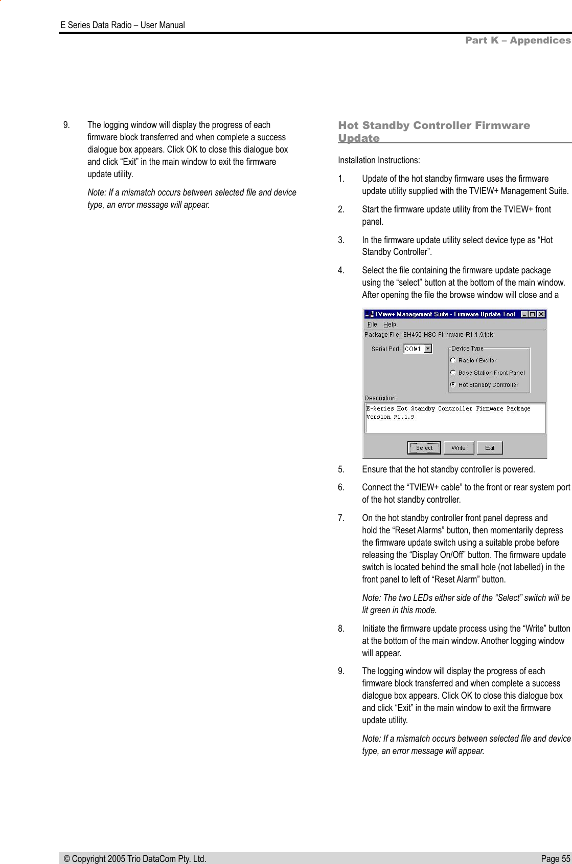
Contents
1.
Advertising Material
2.
ER Quick Start Guide
3.
Installation Guide Part 1
4.
Installation Guide Part 2
5.
Users Manual Part 1
6.
Users Manual Part 2
7.
Users Manual Part 3
8.
USERS MANUAL 1
9.
USERS MANUAL 2
USERS MANUAL 2
Navigation menu
Upload a User Manual
Namespaces
Wiki Guide
HTML
PDF
Info
Views
User Manual
Discussion / Help
Navigation