Trio Datacom ER450-XXF01 REMOTE DATA RADIO User Manual E Series 05 05b indd
Trio Datacom Pty Ltd (a wholly owned company of Schneider Electric) REMOTE DATA RADIO E Series 05 05b indd
UserManual.wiki
>
Trio Datacom
>
ER450-XXF01 User Manual
>
USERS MANUAL 1
Contents
1.
Advertising Material
2.
ER Quick Start Guide
3.
Installation Guide Part 1
4.
Installation Guide Part 2
5.
Users Manual Part 1
6.
Users Manual Part 2
7.
Users Manual Part 3
8.
USERS MANUAL 1
9.
USERS MANUAL 2
USERS MANUAL 1
Navigation menu
Upload a User Manual
Namespaces
Wiki Guide
HTML
PDF
Info
Views
User Manual
Discussion / Help
Navigation
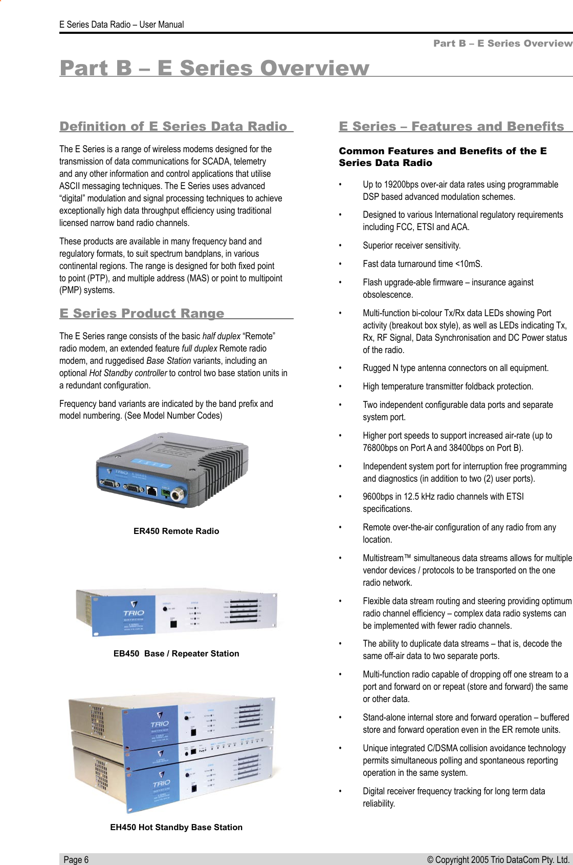
![Page 8E Series Data Radio – User Manual© Copyright 2005 Trio DataCom Pty. Ltd. Model Number CodesPart B – E Series OverviewD, E, H, S & M Series Data Radios - Part Number Matrix = Tyxxx-aabbb-cdeT y x x x -a a b b b -c d eOptions - Base Stations Duplexers* Options - Hot Standby Configurations*0= No Options 0= No Options1= 450MHz Band Reject Typically Internal [DUPLX450BR]Duplexer Antenna36Number Type AntennaConfig Antenna Type7= 450MHz Band Pass Compact [DUPLX450BPC]A- - - Separate Tx & RxB- - Dual [x4] Separate Tx & RxCSingle Internal Single Combined Tx/RxOptions - E and M Series Remotes* DDual [x2] Internal Dual [x2] Combined Tx/Rx0 E Single External Single Combined Tx/RxFDual [x2] External Dual [x2] Combined Tx/RxOptions*0= No OptionsD= Diagnostics - [DIAGS/D, DIAGS/DH, DIAGS/E or DIAGS/EH, DIAGS/M] (D, E & M Series Only)F= Full Duplex Operation [ERFD450] (ER450 only)X= Full Duplex Operation and Diagnostics [ERFD450 & DIAGS/E] (ER450 only)S= SMA Connector (SR450 Remote Only)RF Channel Data Rate & Bandwidth (Internal Modem)D SeriesE SeriesH SeriesA01= ACA 4800bps 12.5kHz001= 12.5kHz (No Modem Fitted)A01= ACA 4800#/ 9600bps 12.5Hz001= 2400bps 12.5KHz / 4800bps 25kHzF01= FCC 115kbpsA02= ACA 9600bps 25kHz002= 25kHz (No Modem Fitted)A02= ACA 9600#/ 19k2bps 25kHz002= 4800bps 12.5KHz / 9600bps 25kHzA01= ACA 115kbpsF01= FCC 9600bps 12.5kHz241= 2400bps in 12.5kHz [24SR]*F01= FCC 9600#/ 19K2bps 12.5kHz003= FCC 9600bps 12.5KHz242= 2400bps in 25kHz [24SR]*F02= FCC 19k2bps 25kHz004= ETSI 4800bps 12.5KHz482= 4800bps in 25kHz [48SR]*E01= ETSI 9600bps 12.5kHz241*= 2400bps 12.5KHz (S Series [24SR]* Compatible)E02= ETSI 19k2bps 25kHz242*= 2400bps 25KHz (S Series [24SR]* Compatible)482*= 4800bps 25KHz (S Series [48SR]* Compatible)Frequency (400 MHz Bands)Frequency (800 & 900 MHz Band) (D, H & S Series Only)M= 395 to 465MHz (Tx & Rx) (M Series Only07= (Tx) 847 to 857MHz (Rx) 923 to 933MHz (D Series only, 1W Full DuplexH= 450 to 520MHz (Tx & Rx) (M Series Only06= (Tx) 923 to 933MHz (Rx) 847 to 857MHz (D Series only, 1W Full Duplex46= 370 to 388MHz (Tx & Rx)90= ISM Unlicensed Band 902 to 928Mhz47= 380 to 396MHz (Tx & Rx)91 = ISM Unlicensed Band 915 to 928Mhz (Australia48= 395 to 406MHz (Tx & Rx)92 = ISM Unlicensed Band 2.4GHz50= 403 to 417MHz (Tx & Rx)58= (Tx) 406 to 421MHz (Rx) 415 to 430MHz59= (Tx) 415 to 430MHz (Rx) 406 to 421MHz56= 418 to 435MHz (Tx & Rx)57 = 428 to 444MHz (Tx & Rx) Note: Other frequency bands available upon request.55 = 436 to 450MHz (Tx & Rx)51 = 450 to 465MHz (Tx & Rx)52 = 465 to 480MHz (Tx & Rx)53 = 480 to 494MHz (Tx & Rx)60 = 490 to 500MHz (Tx & Rx)54 = 505 to 518MHz (Tx & Rx)27 = (Tx) 511 to 515MHz (Rx) 501 to 505MHzGeneric Frequency Band NOTES:240 = ISM 2.4GHz (H Series only) * Additional charges apply. Must be ordered separately. Please refer to price list.450 = 370 to 518MHz (E, M & S Series only) # Provides compatibility with D Series radio900 = 800 / 900MHz (D & H Series only) [ ] Items in [ ] parenthesis refer to actual Trio part numbers** Consult factory for availability.Unit Type ~~ M Series Compatible EB/EH450 Base Stations are Type A01 or F01 R= Remote StationB= Base / Repeater Station (D, E & M Series Only) Standards: ACA - Australian Communications AuthorityH= Hot Standby Base / Repeater (D, E & M Series Only) FCC - Federal Communications CommissionETSI - European Telecommunication Standards InstituteModel TypeD= D Series FamilyE= E Series FamilyH= H Series FamilyM= M Series FamilyS= S Series FamilyExample:E R 4 5 0 -5 1 A 0 2 -D H 0Version: 5/05= 450MHz Band Pass Cavity [DUPLX450BP]= 900MHz Band Pass (76MHz split)[DUPLX852/930]The example shown specifies: E Series, Remote Radio, generic 450MHz band, with a specific frequency of 450MHz to 465MHz, a 9600/19200bps modem, with a bandwidth of 25kHz, diagnostics and Class 1, Div 2 Hazardous Approval (standard).Note: Specify Internally or Externally fitted. Externally fitted duplexers require feeder tails.M Series~~S Series= No Options= Hazardous Environment Class 1, Div 2 and Diagnostics Standard on E Series, Option on M Series [HAZ-APROVAL/M]H](https://usermanual.wiki/Trio-Datacom/ER450-XXF01.USERS-MANUAL-1/User-Guide-628508-Page-8.png)