Trio Datacom ER450-XXF01 Remote Radio Data Modem User Manual temp warning E Series R3
Trio Datacom Pty Ltd (a wholly owned company of Schneider Electric) Remote Radio Data Modem temp warning E Series R3
UserManual.wiki
>
Trio Datacom
>
ER450-XXF01 User Manual
>
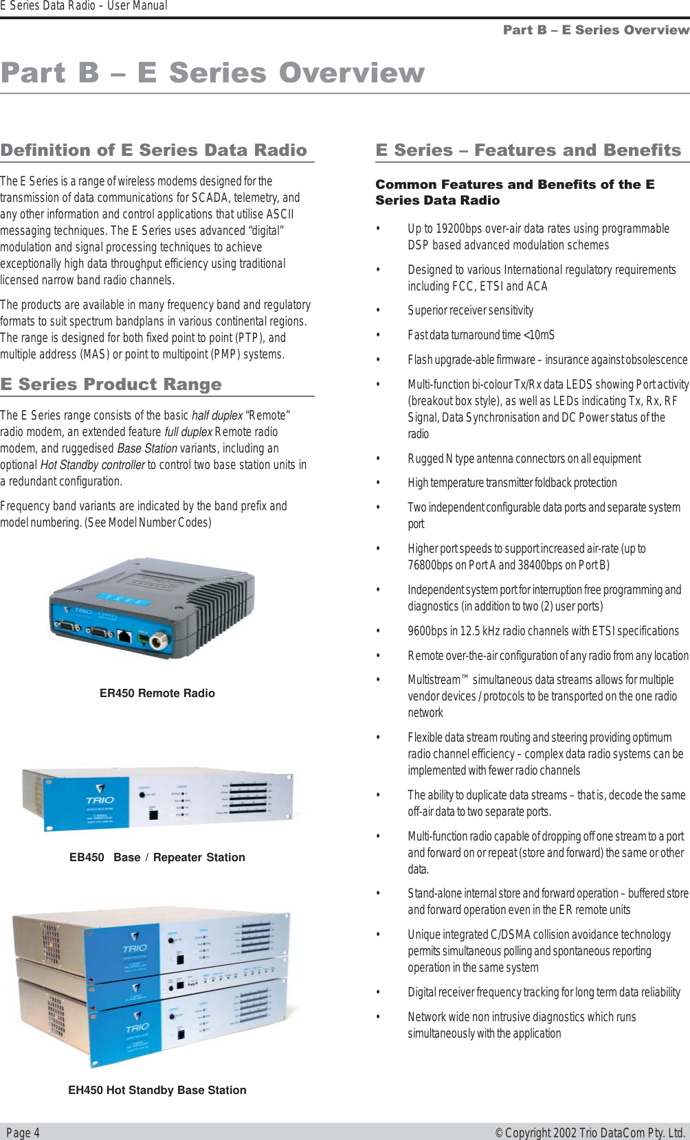
Installation Guide Part 1
Contents
1.
Advertising Material
2.
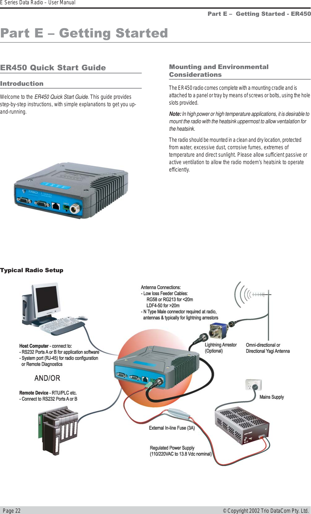
ER Quick Start Guide
3.
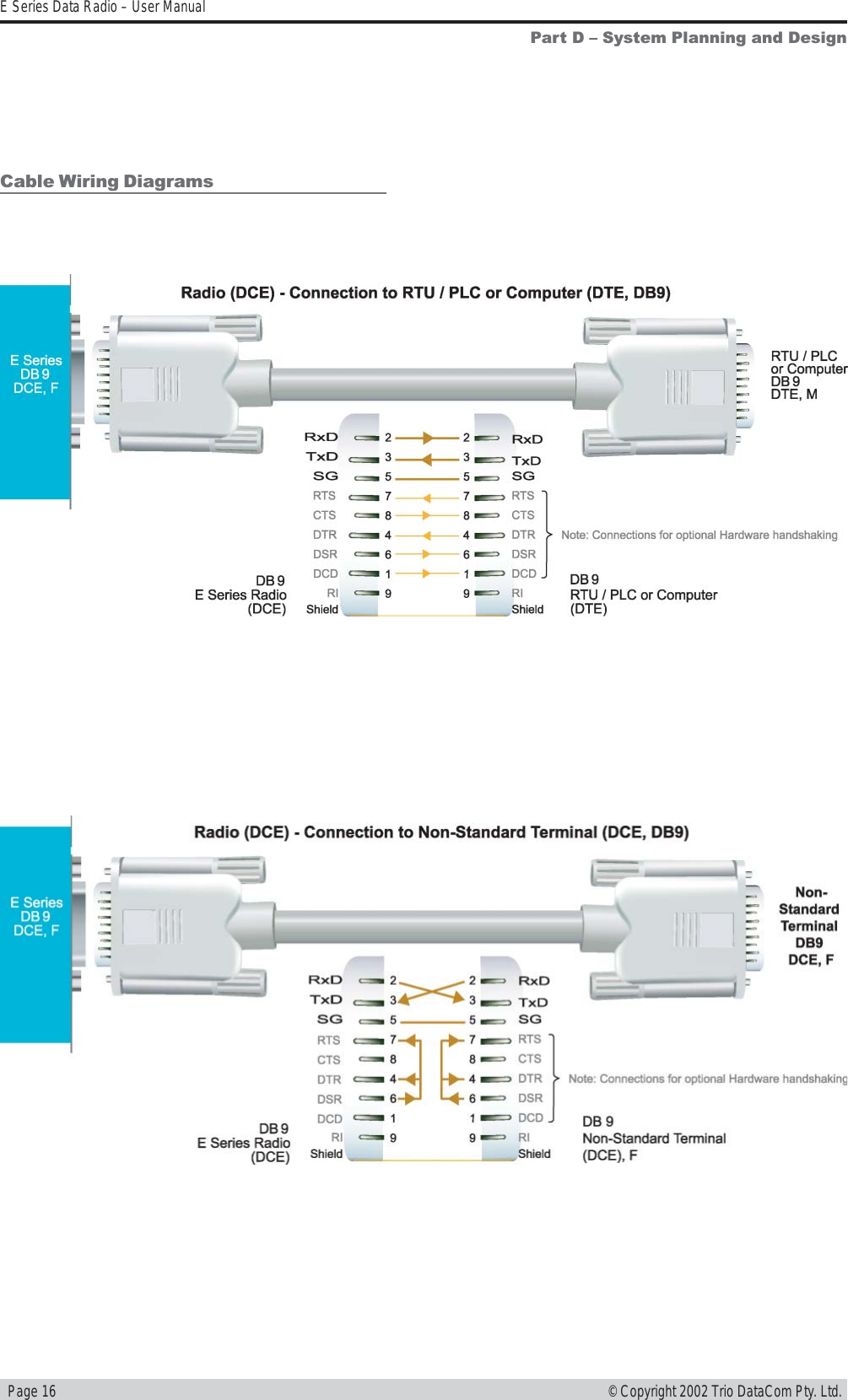
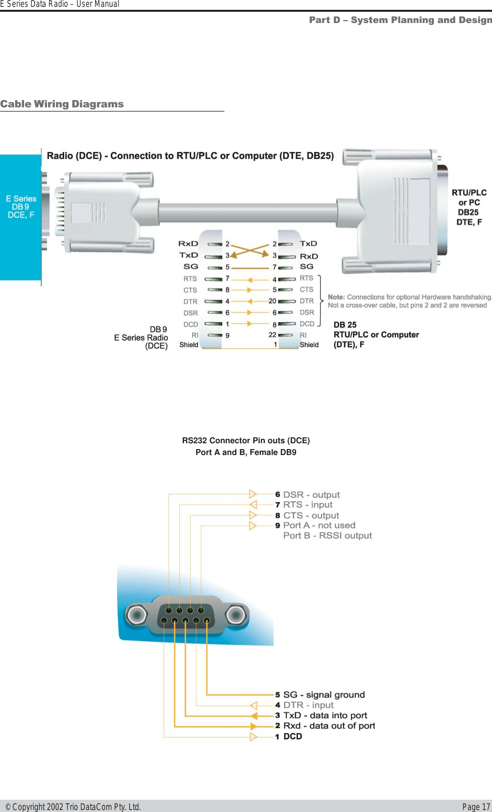
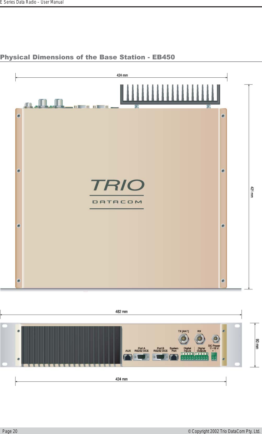
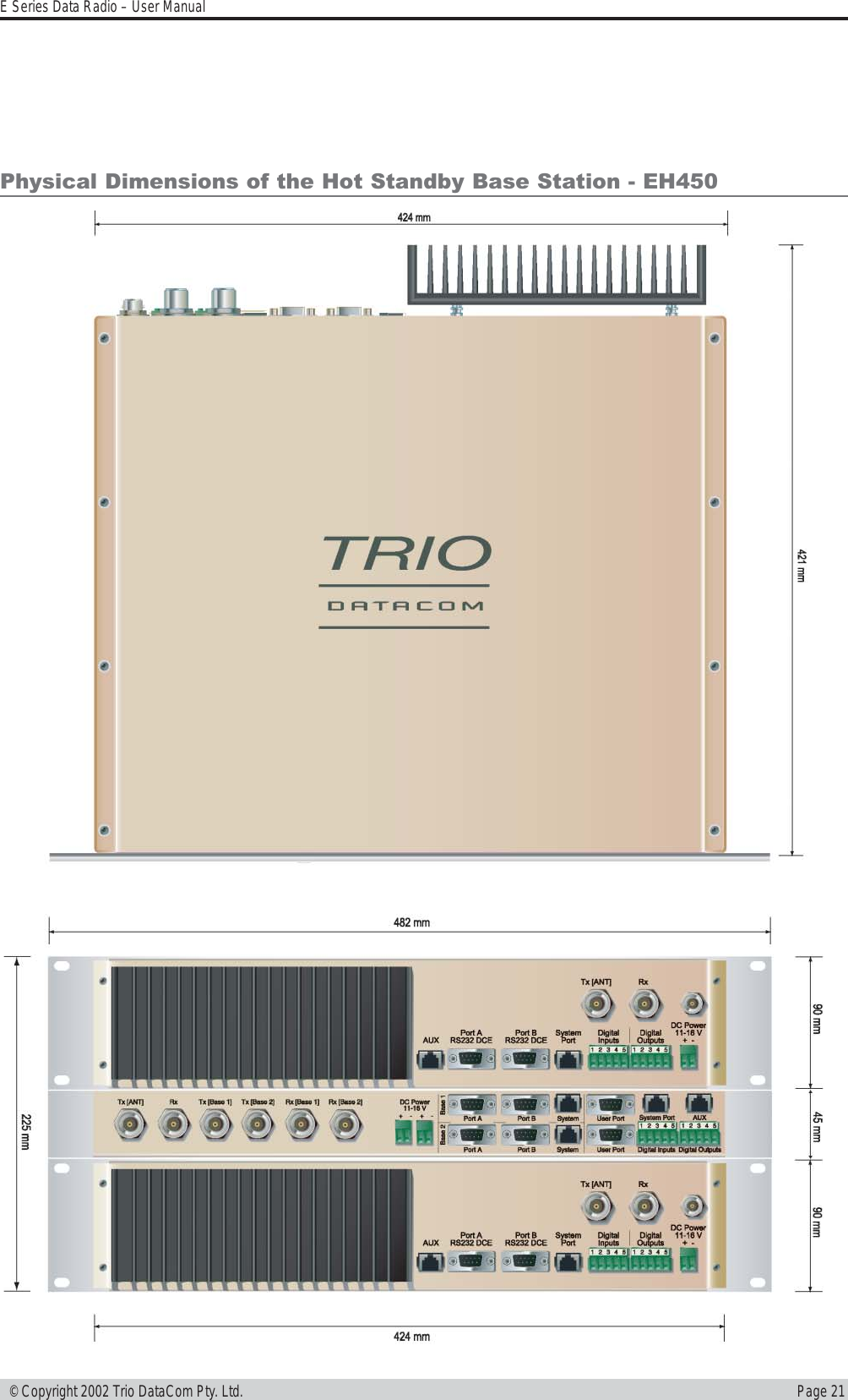
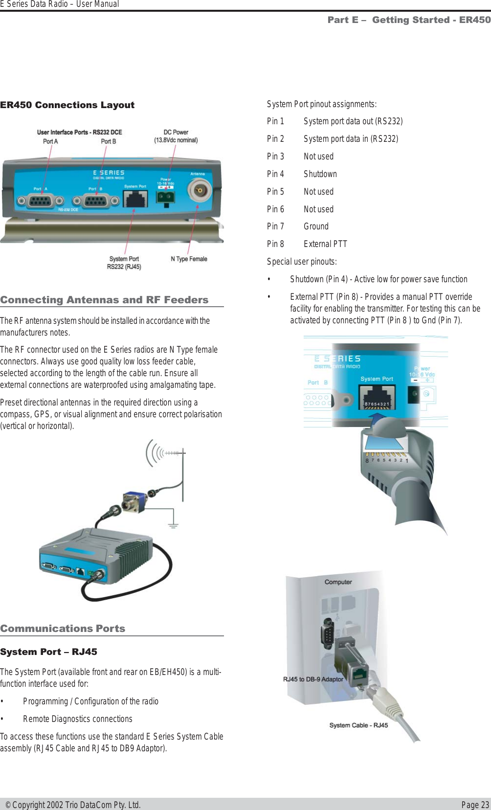
Installation Guide Part 1
4.
Installation Guide Part 2
5.
Users Manual Part 1
6.
Users Manual Part 2
7.
Users Manual Part 3
8.
USERS MANUAL 1
9.
USERS MANUAL 2
Installation Guide Part 1
Navigation menu
Upload a User Manual
Namespaces
Wiki Guide
HTML
PDF
Info
Views
User Manual
Discussion / Help
Navigation
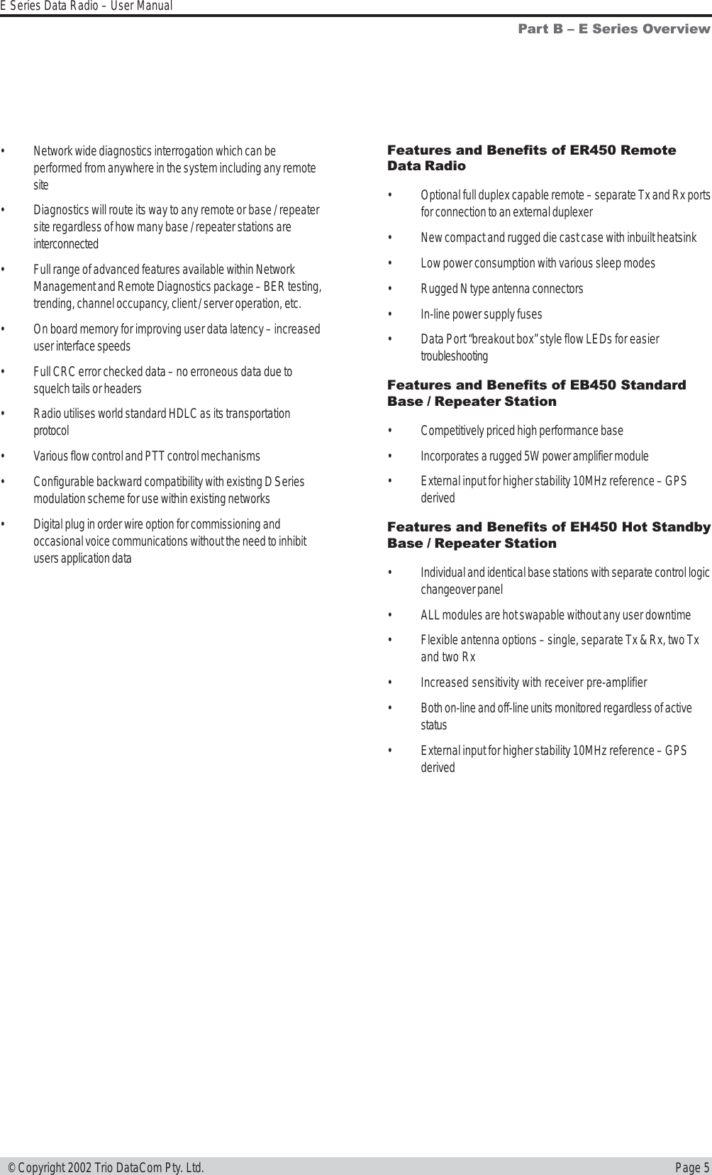
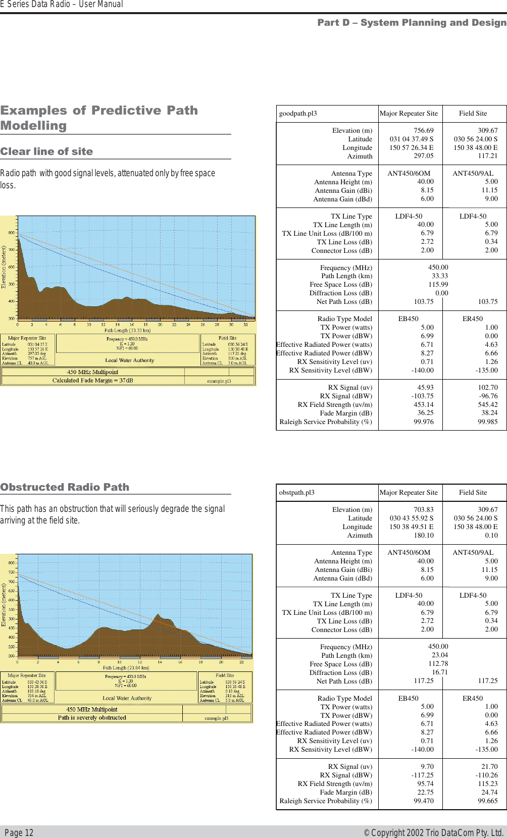
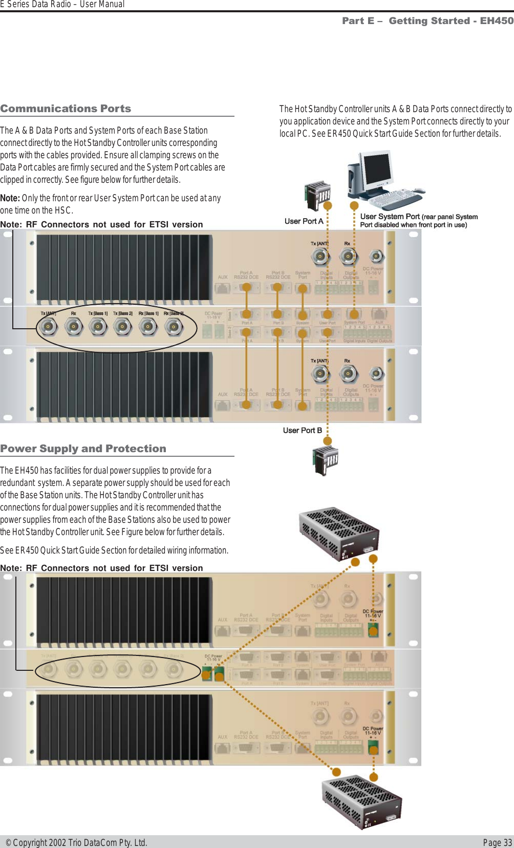
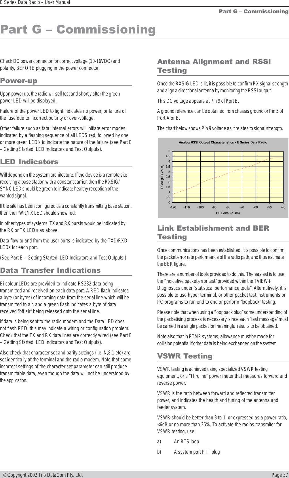
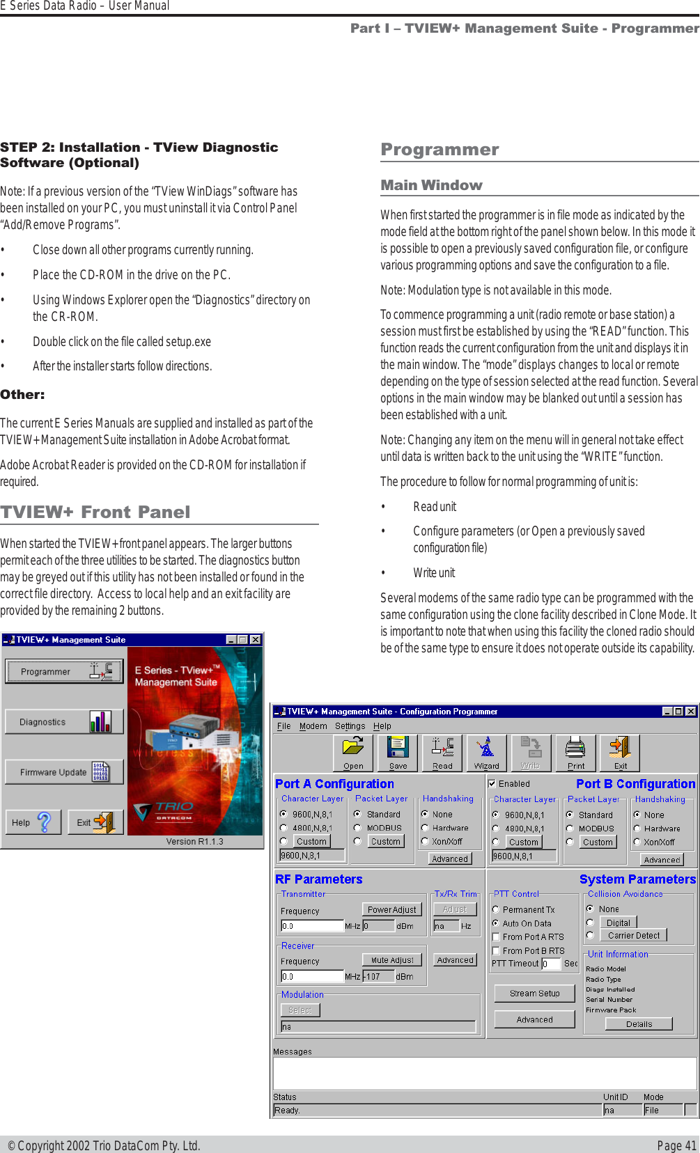
![Page 6E Series Data Radio – User Manual© Copyright 2002 Trio DataCom Pty. Ltd.Model Number CodesD, E & S Series Data Radios - Part Number Matrix = Tyxxx-aabbb-cdT y xxx-aa bbb-cdOptions - Base Stations* Options - Remote Antenna Connector*0= No Options 0= No Options (Standard)1= 450MHz Band Reject [DUPLX450BR]N= N Connector (D Series only)2= 450MHz Band Reject (<9MHz split)[DUPLX450BR/5]S= SMA Connector (SR450 only)3= 450MHz Band Pass [DUPLX450BP]4= 900MHz Band Reject [DUPLX900BR]5= 900MHz Band Pass [DUPLX900BP]6= 900MHz Band Pass (76MHz split)[DUPLX852/930]Note: Specify Internally or Externally fitted. Externally fittered duplexes require feeder tails.Options*0= No OptionsD= Diagnostics - [DIAGS/D, DIAGS/DH, DIAGS/E or DIAGS/EH] (D & E Series Only)H= Extended Temp Option [HITEMP]N= Remote Fitted into NEMA Enclosure [NEMA 4/R]F= Full Duplex Operation [ERFD450] (ER450 only)X= Full Duplex Operation [ERFD450 & DIAGS/E] (ER450 only)RF Channel Data Rate & Bandwidth (Internal Modem)D Series E SeriesA01 = ACA 4800bps in 12.5kHz A01 = ACA 4800#/ 9600bps in 12.5Hz 001 = 12.5kHz (No Modem Fitted)A02 = ACA 9600bps in 25kHz A02 = ACA 9600#/ 19k2bps in 25kHz 002 = 25kHz (No Modem Fitted)F01 = FCC 9600bps in 12.5kHz F01 = FCC 9600#/ 9600bps in 12.5kHz 241 = 2400bps in 12.5kHz [24SR]*F02 = FCC 19k2bps in 25kHz 242 = 2400bps in 25kHz [24SR]*E01 = ETSI 9600bps in 12.5kHz 482 = 4800bps in 25kHz [48SR]*E02 = ETSI 19k2bps in 25kHzFrequency (200 & 400 MHz range) Frequency (900 MHz range) (D & S Series Only)39 = 208 to 240MHz (Tx & Rx) 07 = (Tx) 847 to 857MHz (Rx) 923 to 933MHz (D Series only, 1W Full Duplex)50 = 403 to 417MHz (Tx & Rx) 10 = (Tx) 848 to 858MHz (Rx) 920 to 934MHz58 = (Tx) 406 to 421MHz (Rx) 415 to 430MHz 06 = (Tx) 923 to 933MHz (Rx) 847 to 857MHz (D Series only, 1W Full Duplex)59 = (Tx) 415 to 430MHz (Rx) 406 to 421MHz 11 = (Tx) 920 to 934MHz (Rx) 848 to 858MHz56 = 418 to 435MHz (Tx & Rx) 12 = 855 to 860MHz (Tx & Rx)57 = 428 to 443MHz (Tx & Rx) 14 = (Tx) 925 to 943MHz (Rx) 906 to 924MHz 55 = 436 to 450MHz (Tx & Rx) 15 = (Tx) 904 to 922MHz (Rx) 925 to 943MHz51 = 450 to 465MHz (Tx & Rx) 16 = 924 to 944MHz (Tx & Rx)52 = 465 to 480MHz (Tx & Rx)53 = 480 to 494MHz (Tx & Rx) Note: Other frequency bands available upon request.54 = 505 to 518MHz (Tx & Rx)27 = (Tx) 511 to 515MHz (Rx) 501 to 505MHz48 = 395 to 406MHz (Tx & Rx)Generic Frequency Band200 = 208 to 245MHz (D & S Series only) NOTES:450 = 400 to 518MHz (E & S Series only) * Additional charges apply. Must be ordered seperately. Please refer to price list. 900 = 800 to 960MHz (D & S Series only)# Provides compatibility with D Series radio Items in [ ] parenthesis refer to actual Trio part numbersUnit TypeR= Remote StationB= Base / Repeater Station Standards: ACA - Australian Communications AuthorityS= Standard Base / Repeater Station (D Series Only) FCC - Federal Communications CommissionH= Hot Standby Base / Repeater (D & E Series Only) ETSI - European Telcommunication Standards InstituteModel TypeD= D Series FamilyE= E Series FamilyS= S Series FamilyExample:E R 450-51 A02-D0The above example specifies: E Series, Remote Radio, generic 450MHz band, with a specific frequency of 450MHz to 465MHz,a 96/19.2kbps modem, with a bandwidth of 25kHz, diagnostics and standard N type connector.Version: 11/02S Series](https://usermanual.wiki/Trio-Datacom/ER450-XXF01.Installation-Guide-Part-1/User-Guide-340238-Page-6.png)