UBS Axcera 325A 500-Watt VHF Low-band Television Transmitter User Manual Chapter 2
UBS-Axcera 500-Watt VHF Low-band Television Transmitter Chapter 2
UserManual.wiki
>
UBS Axcera
>
325A User Manual
>
Chapter 2
Contents
1.
Title Page
2.
Table of Contents
3.
Table of Contents Tables and Figures
4.
Chapter 1
5.
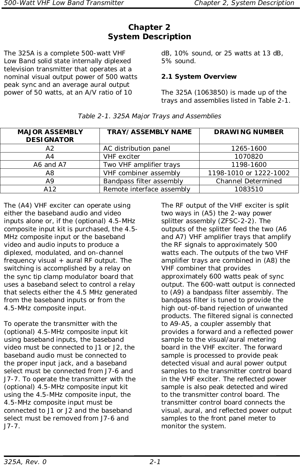
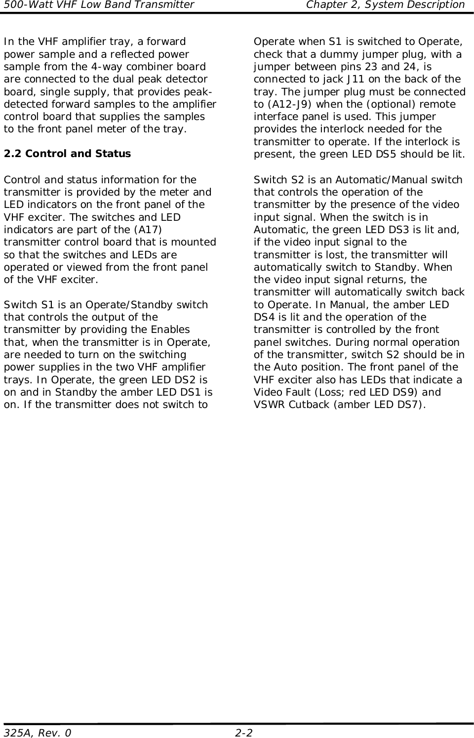
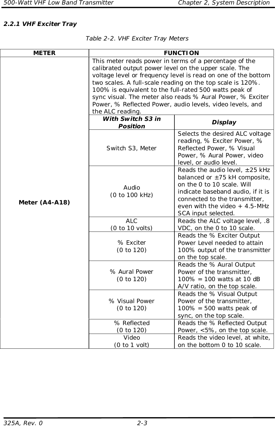
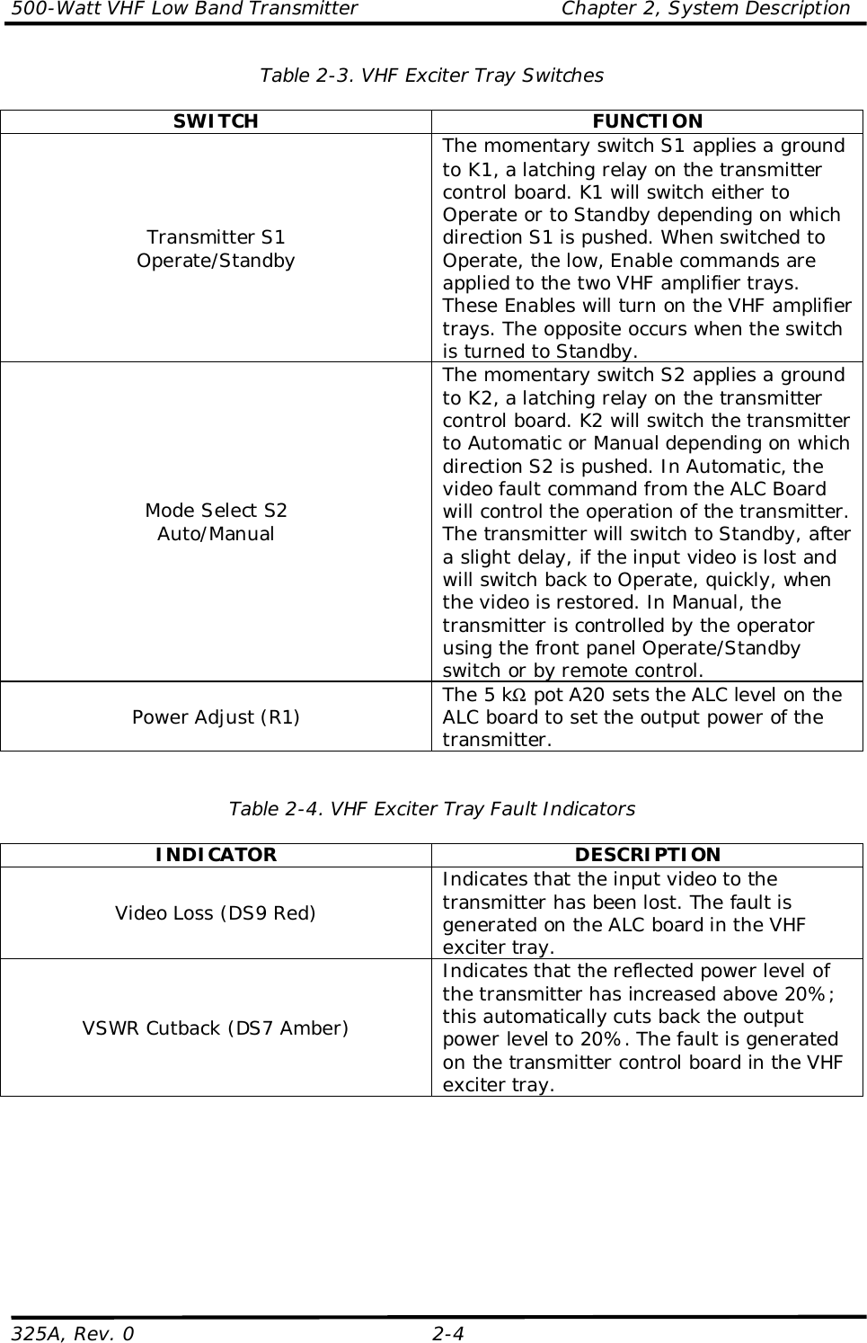
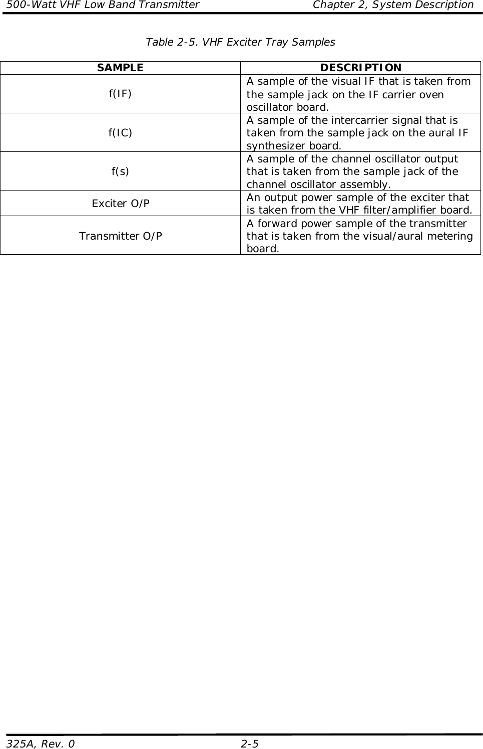
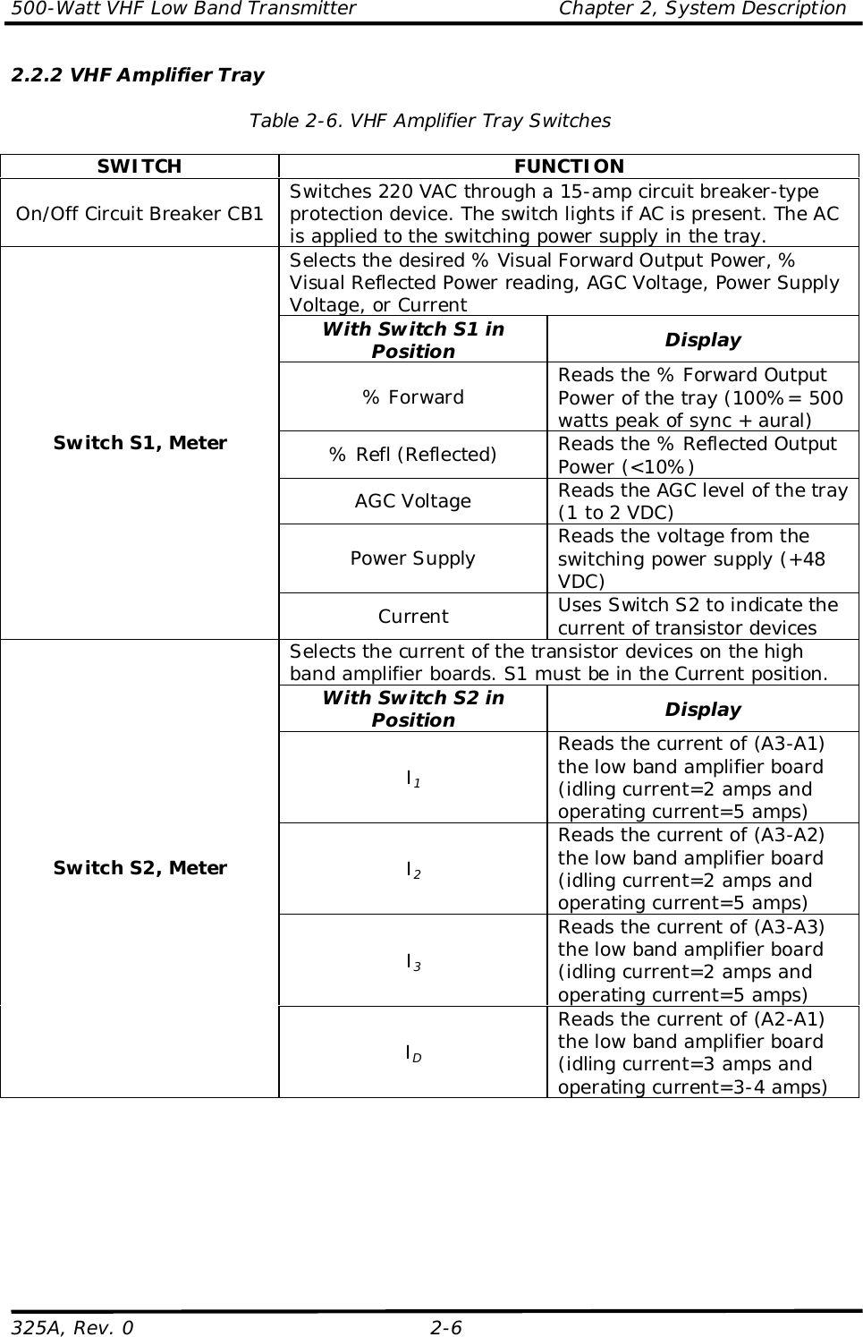
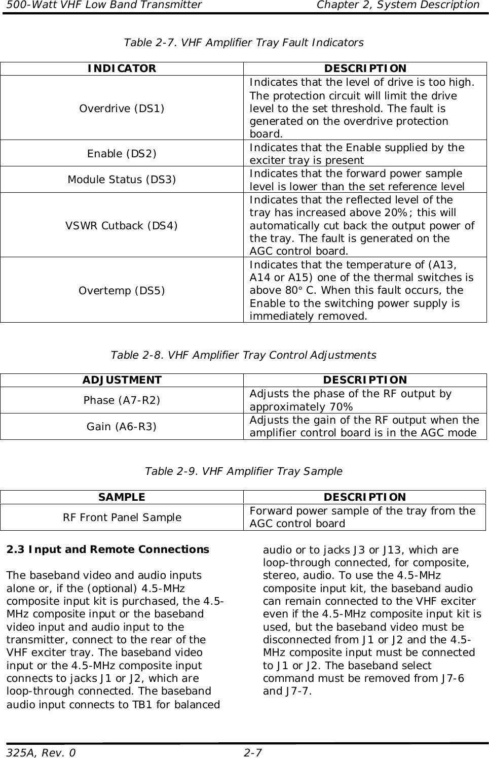
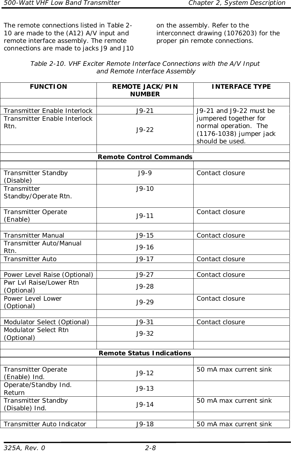
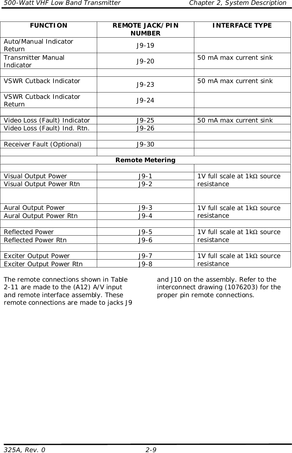
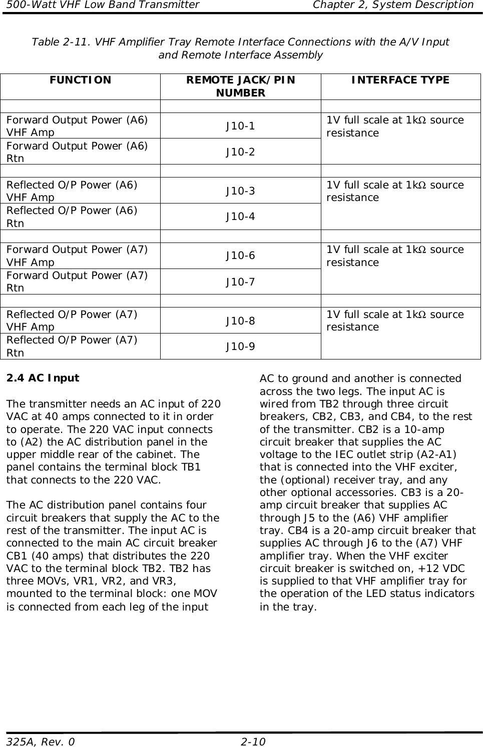
Chapter 2
6.
Chapter 3
7.
Chapter 4
8.
Chapter 5
9.
Appendix A Spec Sheet
10.
Appendix B Log Sheet
11.
Appendix C Drawing
12.
Appendix C Drawing Page 1
13.
Appendix C Drawing Page 2
14.
Appendix D Drawing
Chapter 2
Navigation menu
Upload a User Manual
Namespaces
Wiki Guide
HTML
PDF
Info
Views
User Manual
Discussion / Help
Navigation