UBS Axcera 325A 500-Watt VHF Low-band Television Transmitter User Manual Chapter 3
UBS-Axcera 500-Watt VHF Low-band Television Transmitter Chapter 3
UserManual.wiki
>
UBS Axcera
>
325A User Manual
>
Chapter 3
Contents
1.
Title Page
2.
Table of Contents
3.
Table of Contents Tables and Figures
4.
Chapter 1
5.
Chapter 2
6.
Chapter 3
7.
Chapter 4
8.
Chapter 5
9.
Appendix A Spec Sheet
10.
Appendix B Log Sheet
11.
Appendix C Drawing
12.
Appendix C Drawing Page 1
13.
Appendix C Drawing Page 2
14.
Appendix D Drawing
Chapter 3
Navigation menu
Upload a User Manual
Namespaces
Wiki Guide
HTML
PDF
Info
Views
User Manual
Discussion / Help
Navigation
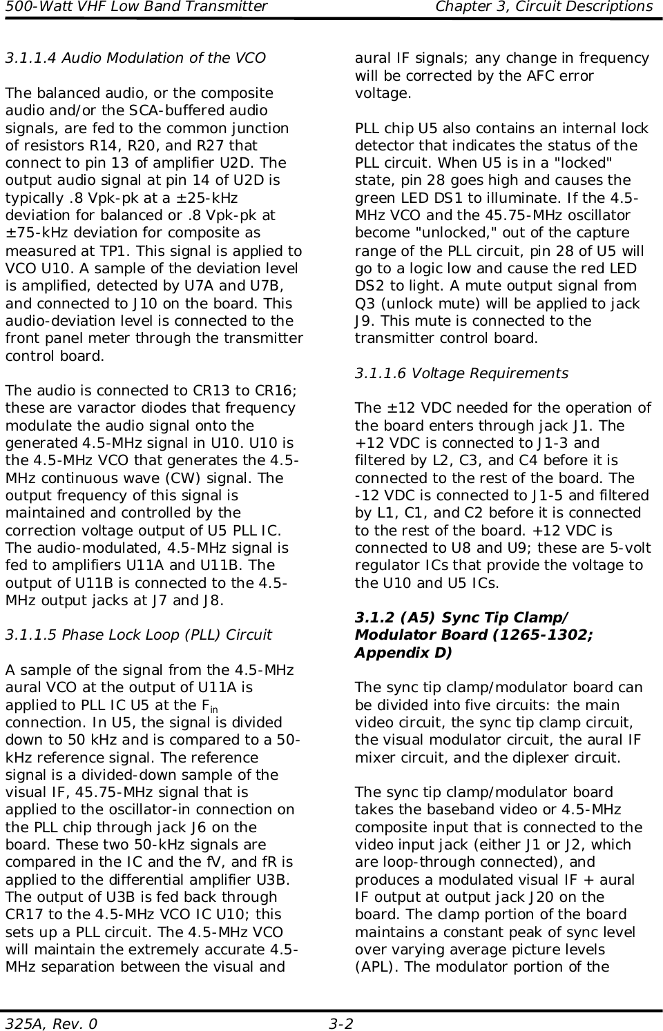
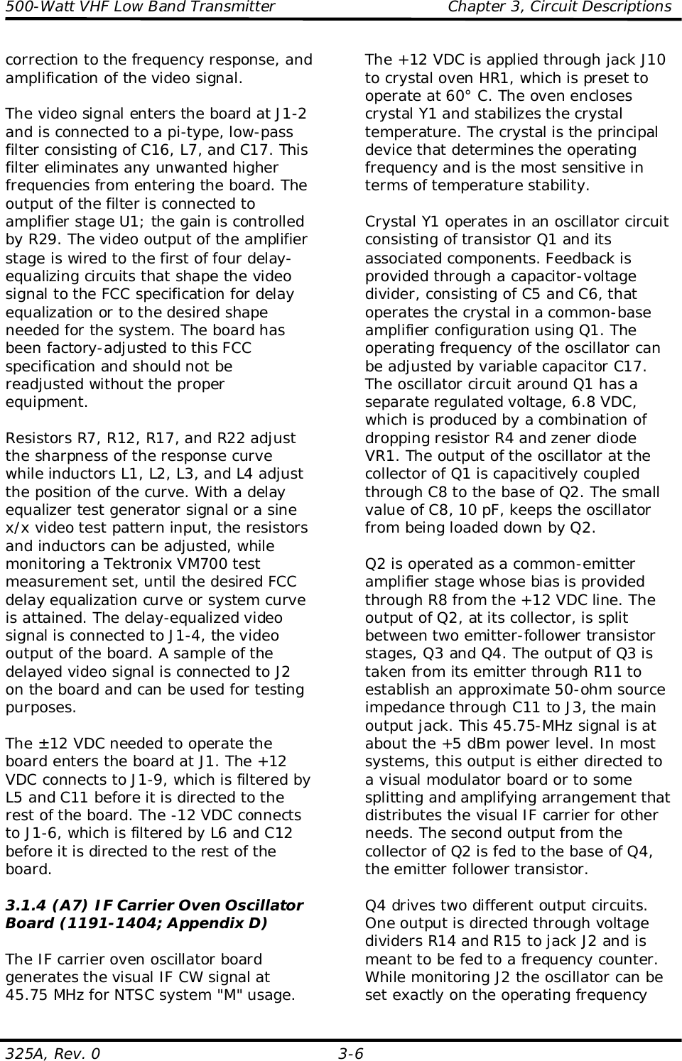
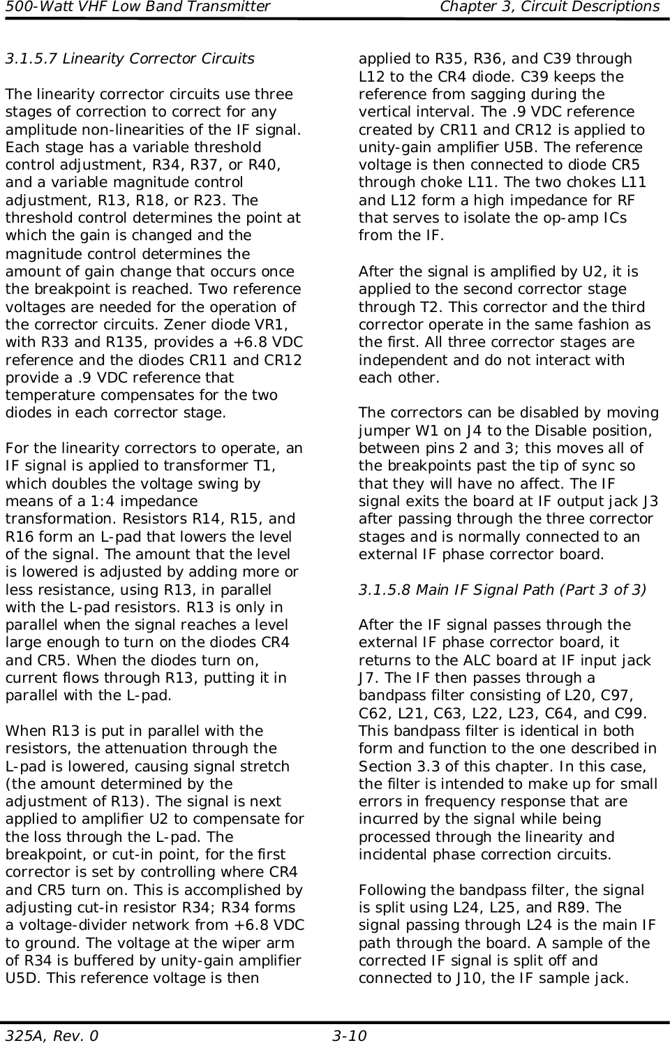
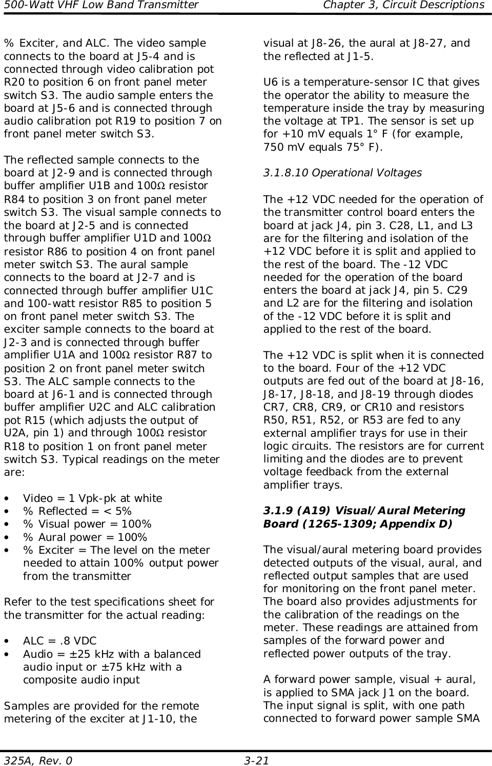
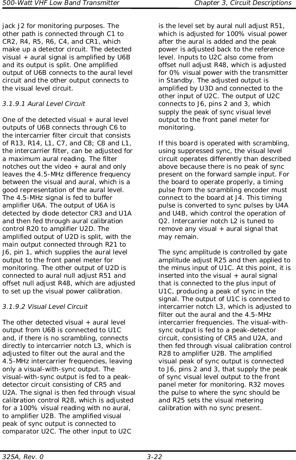
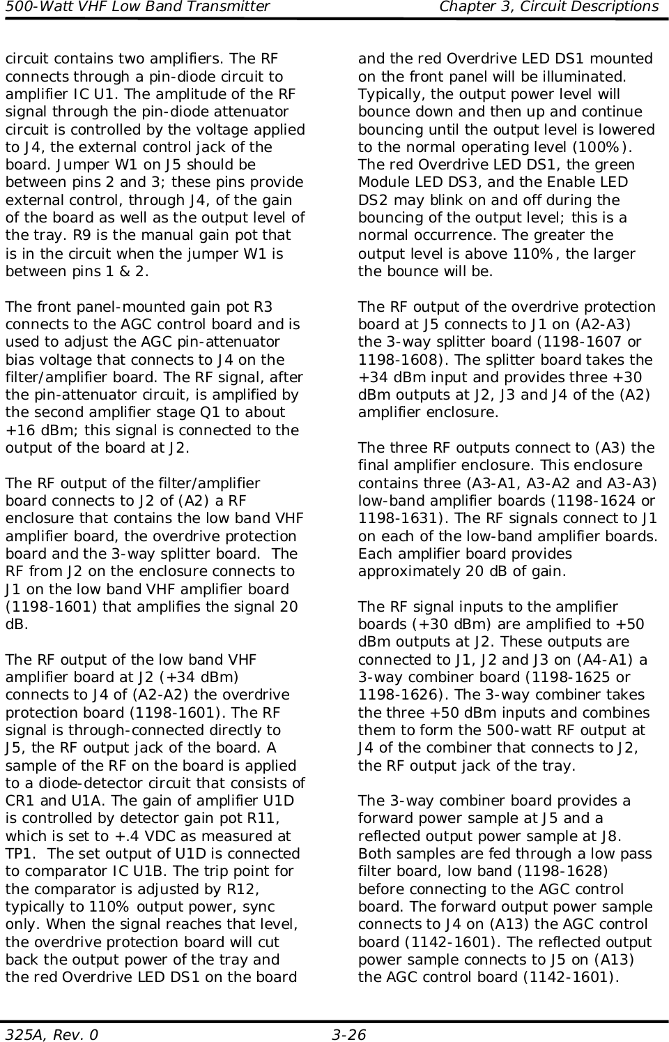
![500-Watt VHF Low Band Transmitter Chapter 3, Circuit Descriptions325A, Rev. 0 3-25Table 3-1. VHF Amplifier Tray Boards and AssembliesMAJOR ASSEMBLYDESIGNATOR BOARD/ASSEMBLY NAME DRAWING NUMBERA1-A1 Phase shifter board(mounted in [A1] an RFenclosure assembly) 1198-1602A1-A2 Filter/amplifier board(mounted in [A1] an RFenclosure assembly) 1198-1606A2-A1 Low band VHF amplifierboard (mounted in [A2] anRF enclosure assembly) 1198-1605A2-A2 Overdrive protection board(mounted in [A2] an RFenclosure assembly) 1198-1601A2-A3 3-way splitter board(mounted in [A2] an RFenclosure assembly)1198-1607 (CH. 2-4) or1198-1608 (CH. 5-6)A3-A1, A3-A2 and A3-A3Three low band VHFamplifier boards (mountedin [A3] an RF enclosureassembly)1198-1624 (CH. 2-4) or1198-1631 (CH. 5-6)A4-A1 3-way combinerboard(mounted in [A4] anRF enclosure assembly)1198-1625 (CH. 2-4) or1198-1626 (CH. 5-6)A4-A2 and A4-A3 Two low pass filter boards(mounted in [A4] an RFenclosure assembly) 1198-1628A5 AGC control board 1142-1601A8 Current metering board 1198-1609A10 +48 VDC switching powersupply assembly VS3-L9-B9-21-CEThe on-channel visual RF or aural RFinput signal (+6 dBm) enters the rear ofthe tray at BNC jack J1 and is fedthrough J1 of the (A1) enclosureassembly to J1 of (A1-A1) the phaseshifter board (1198-1602). The boardprovides a phase shifter adjustment ofthe RF signal that is needed to providemaximum output during the combining ofmultiple VHF amplifier trays in anamplifier array. Front panel-mountedphase shift potentiometer R2 connects toJ3 on the board and controls the phase ofthe RF signal.If the input signal level to the phaseshifter board falls below a preset level, ahigh, which is an input fault, connectsfrom J5 of the board to J14 on the AGCcontrol board. When an input faultoccurs, the AGC control board generatesa fault output at J1, which is connectedto J4 on the filter/amplifier board. Thefault cuts back the RF signal level usingthe pin-diode attenuator circuit on thefilter/amplifier board.The phase-controlled output at J2 of thephase shifter board (+4 dBm) is directedto J7, the input jack of (A1—A2) the filteramplifier board (1198-1606) that is madeup of two circuits. The first circuit is achannel filter that is adjusted for thedesired channel frequency andbandwidth. The filtered output (+2 dBm)is connected to the second circuit; this](https://usermanual.wiki/UBS-Axcera/325A.Chapter-3/User-Guide-265275-Page-25.png)