UBS Axcera 325A 500-Watt VHF Low-band Television Transmitter User Manual Chapter 2
UBS-Axcera 500-Watt VHF Low-band Television Transmitter Chapter 2
Contents
Chapter 2

500-Watt VHF Low Band Transmitter Chapter 2, System Description
325A, Rev. 0 2-1
Chapter 2
System Description
The 325A is a complete 500-watt VHF
Low Band solid state internally diplexed
television transmitter that operates at a
nominal visual output power of 500 watts
peak sync and an average aural output
power of 50 watts, at an A/V ratio of 10
dB, 10% sound, or 25 watts at 13 dB,
5% sound.
2.1 System Overview
The 325A (1063850) is made up of the
trays and assemblies listed in Table 2-1.
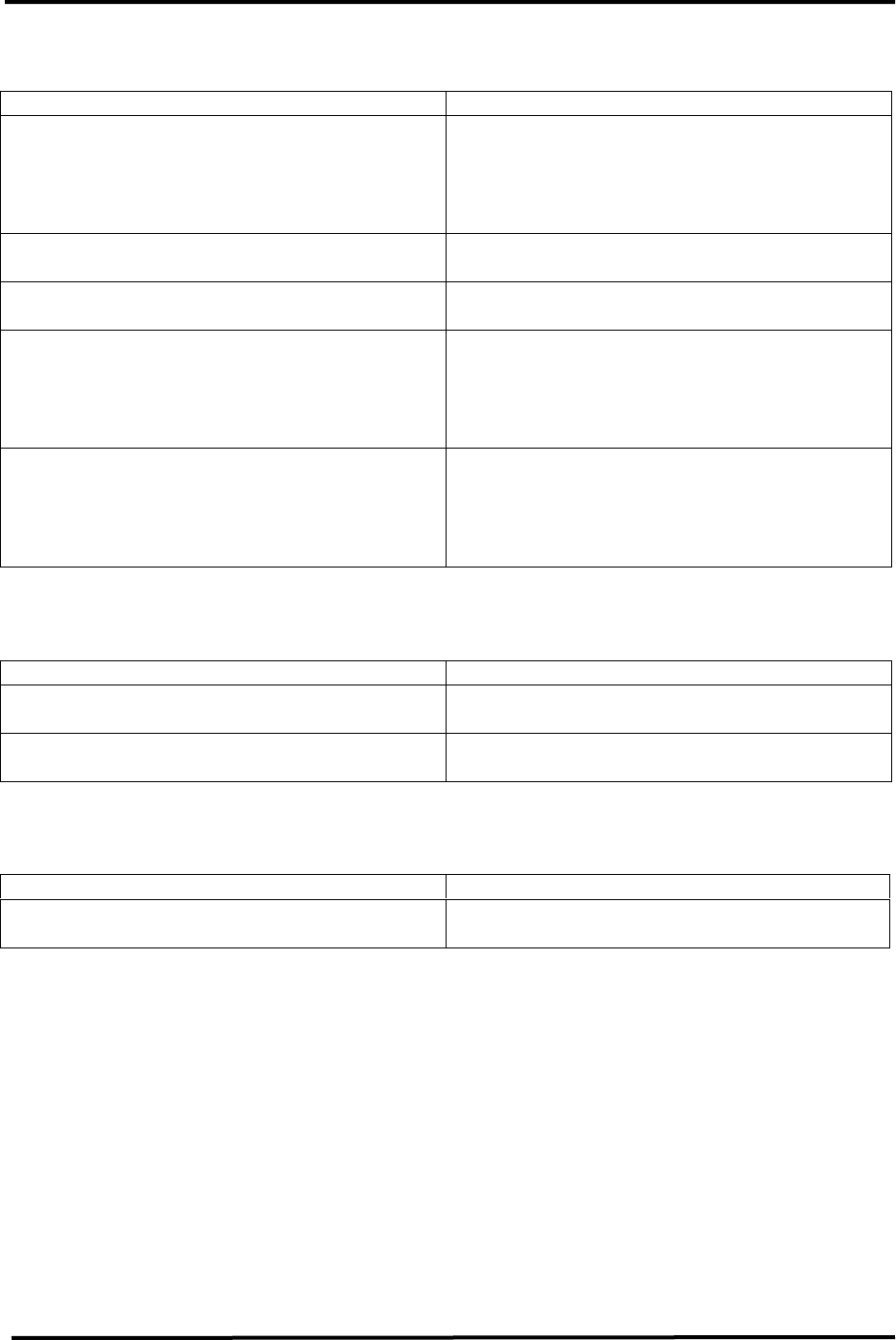
Table 2-1. 325A Major Trays and Assemblies
MAJOR ASSEMBLY
DESIGNATOR TRAY/ASSEMBLY NAME DRAWING NUMBER
A2 AC distribution panel 1265-1600
A4 VHF exciter 1070820
A6 and A7 Two VHF amplifier trays 1198-1600
A8 VHF combiner assembly 1198-1010 or 1222-1002
A9 Bandpass filter assembly Channel Determined
A12 Remote interface assembly 1083510
The (A4) VHF exciter can operate using
either the baseband audio and video
inputs alone or, if the (optional) 4.5-MHz
composite input kit is purchased, the 4.5-
MHz composite input or the baseband
video and audio inputs to produce a
diplexed, modulated, and on-channel
frequency visual + aural RF output. The
switching is accomplished by a relay on
the sync tip clamp modulator board that
uses a baseband select to control a relay
that selects either the 4.5 MHz generated
from the baseband inputs or from the
4.5-MHz composite input.
To operate the transmitter with the
(optional) 4.5-MHz composite input kit
using baseband inputs, the baseband
video must be connected to J1 or J2, the
baseband audio must be connected to
the proper input jack, and a baseband
select must be connected from J7-6 and
J7-7. To operate the transmitter with the
(optional) 4.5-MHz composite input kit
using the 4.5-MHz composite input, the
4.5-MHz composite input must be
connected to J1 or J2 and the baseband
select must be removed from J7-6 and
J7-7.
The RF output of the VHF exciter is split
two ways in (A5) the 2-way power
splitter assembly (ZFSC-2-2). The
outputs of the splitter feed the two (A6
and A7) VHF amplifier trays that amplify
the RF signals to approximately 500
watts each. The outputs of the two VHF
amplifier trays are combined in (A8) the
VHF combiner that provides
approximately 600 watts peak of sync
output. The 600-watt output is connected
to (A9) a bandpass filter assembly. The
bandpass filter is tuned to provide the
high out-of-band rejection of unwanted
products. The filtered signal is connected
to A9-A5, a coupler assembly that
provides a forward and a reflected power
sample to the visual/aural metering
board in the VHF exciter. The forward
sample is processed to provide peak
detected visual and aural power output
samples to the transmitter control board
in the VHF exciter. The reflected power
sample is also peak detected and wired
to the transmitter control board. The
transmitter control board connects the
visual, aural, and reflected power output
samples to the front panel meter to
monitor the system.

500-Watt VHF Low Band Transmitter Chapter 2, System Description
325A, Rev. 0 2-2
In the VHF amplifier tray, a forward
power sample and a reflected power
sample from the 4-way combiner board
are connected to the dual peak detector
board, single supply, that provides peak-
detected forward samples to the amplifier
control board that supplies the samples
to the front panel meter of the tray.
2.2 Control and Status
Control and status information for the
transmitter is provided by the meter and
LED indicators on the front panel of the
VHF exciter. The switches and LED
indicators are part of the (A17)
transmitter control board that is mounted
so that the switches and LEDs are
operated or viewed from the front panel
of the VHF exciter.
Switch S1 is an Operate/Standby switch
that controls the output of the
transmitter by providing the Enables
that, when the transmitter is in Operate,
are needed to turn on the switching
power supplies in the two VHF amplifier
trays. In Operate, the green LED DS2 is
on and in Standby the amber LED DS1 is
on. If the transmitter does not switch to
Operate when S1 is switched to Operate,
check that a dummy jumper plug, with a
jumper between pins 23 and 24, is
connected to jack J11 on the back of the
tray. The jumper plug must be connected
to (A12-J9) when the (optional) remote
interface panel is used. This jumper
provides the interlock needed for the
transmitter to operate. If the interlock is
present, the green LED DS5 should be lit.
Switch S2 is an Automatic/Manual switch
that controls the operation of the
transmitter by the presence of the video
input signal. When the switch is in
Automatic, the green LED DS3 is lit and,
if the video input signal to the
transmitter is lost, the transmitter will
automatically switch to Standby. When
the video input signal returns, the
transmitter will automatically switch back
to Operate. In Manual, the amber LED
DS4 is lit and the operation of the
transmitter is controlled by the front
panel switches. During normal operation
of the transmitter, switch S2 should be in
the Auto position. The front panel of the
VHF exciter also has LEDs that indicate a
Video Fault (Loss; red LED DS9) and
VSWR Cutback (amber LED DS7).

500-Watt VHF Low Band Transmitter Chapter 2, System Description
325A, Rev. 0 2-3
2.2.1 VHF Exciter Tray
Table 2-2. VHF Exciter Tray Meters
METER FUNCTION
This meter reads power in terms of a percentage of the
calibrated output power level on the upper scale. The
voltage level or frequency level is read on one of the bottom
two scales. A full-scale reading on the top scale is 120%.
100% is equivalent to the full-rated 500 watts peak of
sync visual. The meter also reads % Aural Power, % Exciter
Power, % Reflected Power, audio levels, video levels, and
the ALC reading.
With Switch S3 in
Position Display
Switch S3, Meter
Selects the desired ALC voltage
reading, % Exciter Power, %
Reflected Power, % Visual
Power, % Aural Power, video
level, or audio level.
Audio
(0 to 100 kHz)
Reads the audio level, ±25 kHz
balanced or ±75 kH composite,
on the 0 to 10 scale. Will
indicate baseband audio, if it is
connected to the transmitter,
even with the video + 4.5-MHz
SCA input selected.
ALC
(0 to 10 volts) Reads the ALC voltage level, .8
VDC, on the 0 to 10 scale.
% Exciter
(0 to 120)
Reads the % Exciter Output
Power Level needed to attain
100% output of the transmitter
on the top scale.
% Aural Power
(0 to 120)
Reads the % Aural Output
Power of the transmitter,
100% = 100 watts at 10 dB
A/V ratio, on the top scale.
% Visual Power
(0 to 120)
Reads the % Visual Output
Power of the transmitter,
100% = 500 watts peak of
sync, on the top scale.
% Reflected
(0 to 120) Reads the % Reflected Output
Power, <5%, on the top scale.
Meter (A4-A18)
Video
(0 to 1 volt) Reads the video level, at white,
on the bottom 0 to 10 scale.

500-Watt VHF Low Band Transmitter Chapter 2, System Description
325A, Rev. 0 2-4
Table 2-3. VHF Exciter Tray Switches
SWITCH FUNCTION
Transmitter S1
Operate/Standby
The momentary switch S1 applies a ground
to K1, a latching relay on the transmitter
control board. K1 will switch either to
Operate or to Standby depending on which
direction S1 is pushed. When switched to
Operate, the low, Enable commands are
applied to the two VHF amplifier trays.
These Enables will turn on the VHF amplifier
trays. The opposite occurs when the switch
is turned to Standby.
Mode Select S2
Auto/Manual
The momentary switch S2 applies a ground
to K2, a latching relay on the transmitter
control board. K2 will switch the transmitter
to Automatic or Manual depending on which
direction S2 is pushed. In Automatic, the
video fault command from the ALC Board
will control the operation of the transmitter.
The transmitter will switch to Standby, after
a slight delay, if the input video is lost and
will switch back to Operate, quickly, when
the video is restored. In Manual, the
transmitter is controlled by the operator
using the front panel Operate/Standby
switch or by remote control.
Power Adjust (R1) The 5 kΩ pot A20 sets the ALC level on the
ALC board to set the output power of the
transmitter.
Table 2-4. VHF Exciter Tray Fault Indicators
INDICATOR DESCRIPTION
Video Loss (DS9 Red)
Indicates that the input video to the
transmitter has been lost. The fault is
generated on the ALC board in the VHF
exciter tray.
VSWR Cutback (DS7 Amber)
Indicates that the reflected power level of
the transmitter has increased above 20%;
this automatically cuts back the output
power level to 20%. The fault is generated
on the transmitter control board in the VHF
exciter tray.

500-Watt VHF Low Band Transmitter Chapter 2, System Description
325A, Rev. 0 2-5
Table 2-5. VHF Exciter Tray Samples
SAMPLE DESCRIPTION
f(IF) A sample of the visual IF that is taken from
the sample jack on the IF carrier oven
oscillator board.
f(IC) A sample of the intercarrier signal that is
taken from the sample jack on the aural IF
synthesizer board.
f(s) A sample of the channel oscillator output
that is taken from the sample jack of the
channel oscillator assembly.
Exciter O/P An output power sample of the exciter that
is taken from the VHF filter/amplifier board.
Transmitter O/P A forward power sample of the transmitter
that is taken from the visual/aural metering
board.

500-Watt VHF Low Band Transmitter Chapter 2, System Description
325A, Rev. 0 2-6
2.2.2 VHF Amplifier Tray
Table 2-6. VHF Amplifier Tray Switches
SWITCH FUNCTION
On/Off Circuit Breaker CB1 Switches 220 VAC through a 15-amp circuit breaker-type
protection device. The switch lights if AC is present. The AC
is applied to the switching power supply in the tray.
Selects the desired % Visual Forward Output Power, %
Visual Reflected Power reading, AGC Voltage, Power Supply
Voltage, or Current
With Switch S1 in
Position Display
% Forward Reads the % Forward Output
Power of the tray (100%= 500
watts peak of sync + aural)
% Refl (Reflected) Reads the % Reflected Output
Power (<10%)
AGC Voltage Reads the AGC level of the tray
(1 to 2 VDC)
Power Supply Reads the voltage from the
switching power supply (+48
VDC)
Switch S1, Meter
Current Uses Switch S2 to indicate the
current of transistor devices
Selects the current of the transistor devices on the high
band amplifier boards. S1 must be in the Current position.
With Switch S2 in
Position Display
I1
Reads the current of (A3-A1)
the low band amplifier board
(idling current=2 amps and
operating current=5 amps)
I2
Reads the current of (A3-A2)
the low band amplifier board
(idling current=2 amps and
operating current=5 amps)
I3
Reads the current of (A3-A3)
the low band amplifier board
(idling current=2 amps and
operating current=5 amps)
Switch S2, Meter
ID
Reads the current of (A2-A1)
the low band amplifier board
(idling current=3 amps and
operating current=3-4 amps)
500-Watt VHF Low Band Transmitter Chapter 2, System Description
325A, Rev. 0 2-7
Table 2-7. VHF Amplifier Tray Fault Indicators
INDICATOR DESCRIPTION
Overdrive (DS1)
Indicates that the level of drive is too high.
The protection circuit will limit the drive
level to the set threshold. The fault is
generated on the overdrive protection
board.
Enable (DS2) Indicates that the Enable supplied by the
exciter tray is present
Module Status (DS3) Indicates that the forward power sample
level is lower than the set reference level
VSWR Cutback (DS4)
Indicates that the reflected level of the
tray has increased above 20%; this will
automatically cut back the output power of
the tray. The fault is generated on the
AGC control board.
Overtemp (DS5)
Indicates that the temperature of (A13,
A14 or A15) one of the thermal switches is
above 80° C. When this fault occurs, the
Enable to the switching power supply is
immediately removed.
Table 2-8. VHF Amplifier Tray Control Adjustments
ADJUSTMENT DESCRIPTION
Phase (A7-R2) Adjusts the phase of the RF output by
approximately 70%
Gain (A6-R3) Adjusts the gain of the RF output when the
amplifier control board is in the AGC mode
Table 2-9. VHF Amplifier Tray Sample
SAMPLE DESCRIPTION
RF Front Panel Sample Forward power sample of the tray from the
AGC control board
2.3 Input and Remote Connections
The baseband video and audio inputs
alone or, if the (optional) 4.5-MHz
composite input kit is purchased, the 4.5-
MHz composite input or the baseband
video input and audio input to the
transmitter, connect to the rear of the
VHF exciter tray. The baseband video
input or the 4.5-MHz composite input
connects to jacks J1 or J2, which are
loop-through connected. The baseband
audio input connects to TB1 for balanced
audio or to jacks J3 or J13, which are
loop-through connected, for composite,
stereo, audio. To use the 4.5-MHz
composite input kit, the baseband audio
can remain connected to the VHF exciter
even if the 4.5-MHz composite input kit is
used, but the baseband video must be
disconnected from J1 or J2 and the 4.5-
MHz composite input must be connected
to J1 or J2. The baseband select
command must be removed from J7-6
and J7-7.

500-Watt VHF Low Band Transmitter Chapter 2, System Description
325A, Rev. 0 2-8
The remote connections listed in Table 2-
10 are made to the (A12) A/V input and
remote interface assembly. The remote
connections are made to jacks J9 and J10
on the assembly. Refer to the
interconnect drawing (1076203) for the
proper pin remote connections.
Table 2-10. VHF Exciter Remote Interface Connections with the A/V Input
and Remote Interface Assembly
FUNCTION REMOTE JACK/PIN
NUMBER INTERFACE TYPE
Transmitter Enable Interlock J9-21
Transmitter Enable Interlock
Rtn. J9-22
J9-21 and J9-22 must be
jumpered together for
normal operation. The
(1176-1038) jumper jack
should be used.
Remote Control Commands
Transmitter Standby
(Disable) J9-9 Contact closure
Transmitter
Standby/Operate Rtn. J9-10
Transmitter Operate
(Enable) J9-11 Contact closure
Transmitter Manual J9-15 Contact closure
Transmitter Auto/Manual
Rtn. J9-16
Transmitter Auto J9-17 Contact closure
Power Level Raise (Optional) J9-27 Contact closure
Pwr Lvl Raise/Lower Rtn
(Optional) J9-28
Power Level Lower
(Optional) J9-29 Contact closure
Modulator Select (Optional) J9-31 Contact closure
Modulator Select Rtn
(Optional) J9-32
Remote Status Indications
Transmitter Operate
(Enable) Ind. J9-12 50 mA max current sink
Operate/Standby Ind.
Return J9-13
Transmitter Standby
(Disable) Ind. J9-14 50 mA max current sink
Transmitter Auto Indicator J9-18 50 mA max current sink

500-Watt VHF Low Band Transmitter Chapter 2, System Description
325A, Rev. 0 2-9
FUNCTION REMOTE JACK/PIN
NUMBER INTERFACE TYPE
Auto/Manual Indicator
Return J9-19
Transmitter Manual
Indicator J9-20 50 mA max current sink
VSWR Cutback Indicator J9-23 50 mA max current sink
VSWR Cutback Indicator
Return J9-24
Video Loss (Fault) Indicator J9-25 50 mA max current sink
Video Loss (Fault) Ind. Rtn. J9-26
Receiver Fault (Optional) J9-30
Remote Metering
Visual Output Power J9-1
Visual Output Power Rtn J9-2 1V full scale at 1kΩ source
resistance
Aural Output Power J9-3
Aural Output Power Rtn J9-4 1V full scale at 1kΩ source
resistance
Reflected Power J9-5
Reflected Power Rtn J9-6 1V full scale at 1kΩ source
resistance
Exciter Output Power J9-7
Exciter Output Power Rtn J9-8 1V full scale at 1kΩ source
resistance
The remote connections shown in Table
2-11 are made to the (A12) A/V input
and remote interface assembly. These
remote connections are made to jacks J9
and J10 on the assembly. Refer to the
interconnect drawing (1076203) for the
proper pin remote connections.

500-Watt VHF Low Band Transmitter Chapter 2, System Description
325A, Rev. 0 2-10
Table 2-11. VHF Amplifier Tray Remote Interface Connections with the A/V Input
and Remote Interface Assembly
FUNCTION REMOTE JACK/PIN
NUMBER INTERFACE TYPE
Forward Output Power (A6)
VHF Amp J10-1
Forward Output Power (A6)
Rtn J10-2
1V full scale at 1kΩ source
resistance
Reflected O/P Power (A6)
VHF Amp J10-3
Reflected O/P Power (A6)
Rtn J10-4
1V full scale at 1kΩ source
resistance
Forward Output Power (A7)
VHF Amp J10-6
Forward Output Power (A7)
Rtn J10-7
1V full scale at 1kΩ source
resistance
Reflected O/P Power (A7)
VHF Amp J10-8
Reflected O/P Power (A7)
Rtn J10-9
1V full scale at 1kΩ source
resistance
2.4 AC Input
The transmitter needs an AC input of 220
VAC at 40 amps connected to it in order
to operate. The 220 VAC input connects
to (A2) the AC distribution panel in the
upper middle rear of the cabinet. The
panel contains the terminal block TB1
that connects to the 220 VAC.
The AC distribution panel contains four
circuit breakers that supply the AC to the
rest of the transmitter. The input AC is
connected to the main AC circuit breaker
CB1 (40 amps) that distributes the 220
VAC to the terminal block TB2. TB2 has
three MOVs, VR1, VR2, and VR3,
mounted to the terminal block: one MOV
is connected from each leg of the input
AC to ground and another is connected
across the two legs. The input AC is
wired from TB2 through three circuit
breakers, CB2, CB3, and CB4, to the rest
of the transmitter. CB2 is a 10-amp
circuit breaker that supplies the AC
voltage to the IEC outlet strip (A2-A1)
that is connected into the VHF exciter,
the (optional) receiver tray, and any
other optional accessories. CB3 is a 20-
amp circuit breaker that supplies AC
through J5 to the (A6) VHF amplifier
tray. CB4 is a 20-amp circuit breaker that
supplies AC through J6 to the (A7) VHF
amplifier tray. When the VHF exciter
circuit breaker is switched on, +12 VDC
is supplied to that VHF amplifier tray for
the operation of the LED status indicators
in the tray.