WIMAN Systems WIMAN2A24 FHSS RF Modem User Manual Manual01
WIMAN Systems Inc FHSS RF Modem Manual01
UserManual.wiki
>
WIMAN Systems
>
WIMAN2A24 User Manual
>
Manual01
Contents
1.
Manual01
2.
Manual02
3.
Manual03
4.
Manual6
5.
Manual7
6.
Manualpage2
Manual01
Navigation menu
Upload a User Manual
Namespaces
Wiki Guide
HTML
PDF
Info
Views
User Manual
Discussion / Help
Navigation
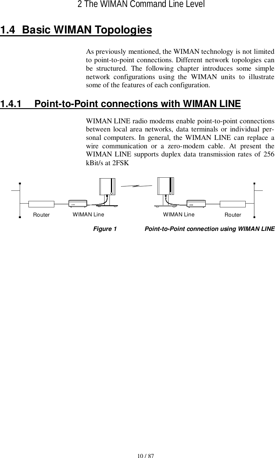
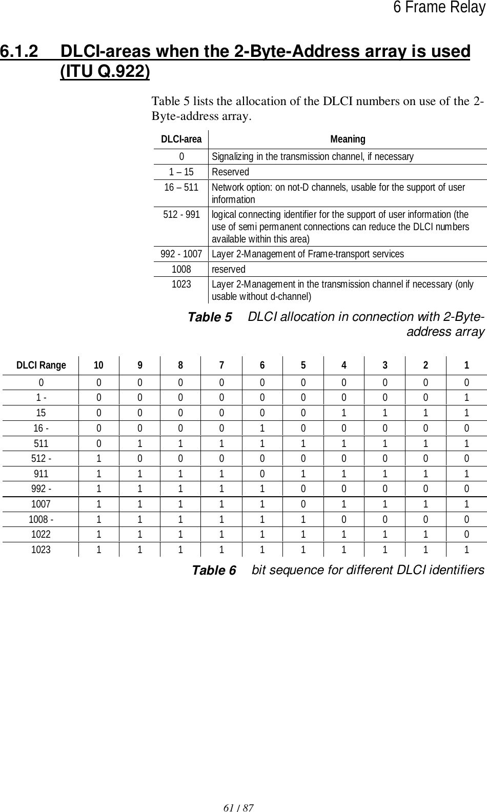
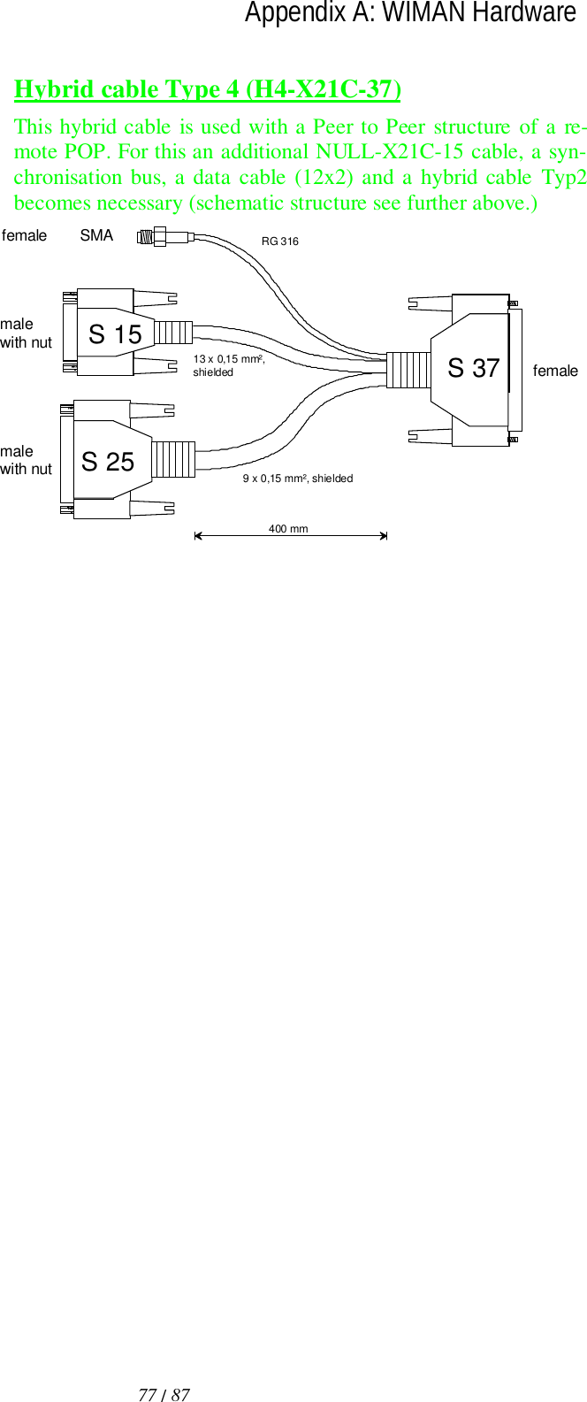
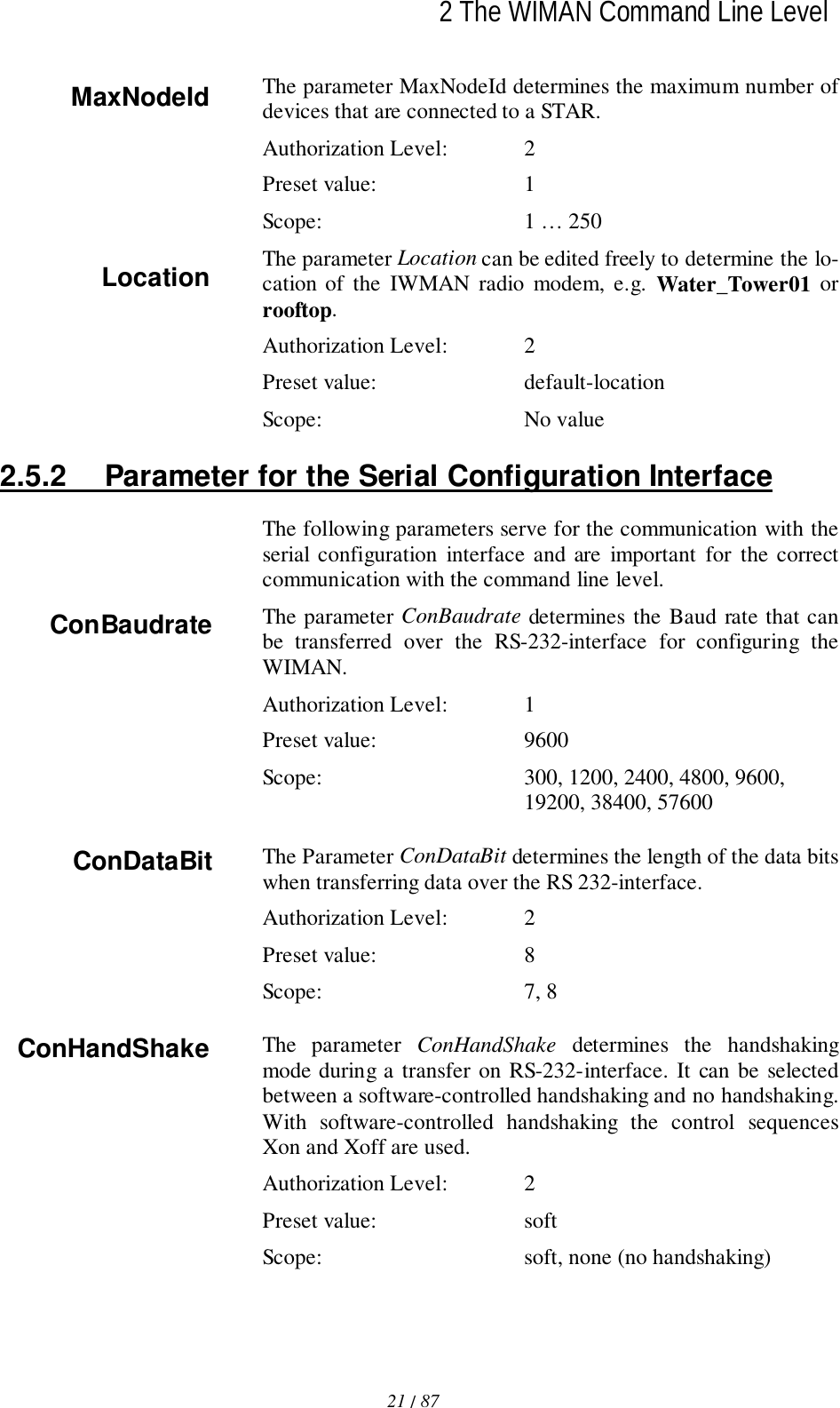
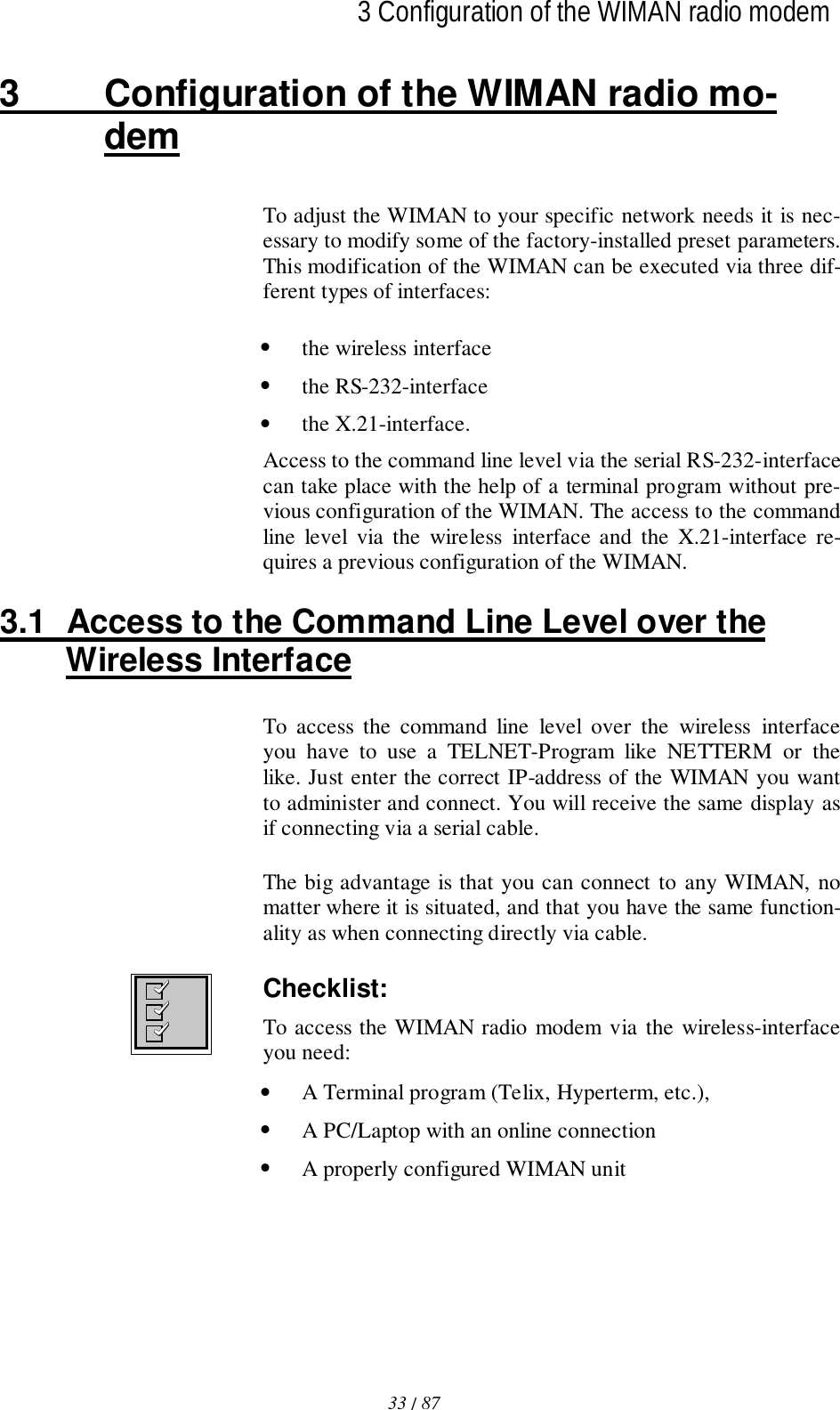
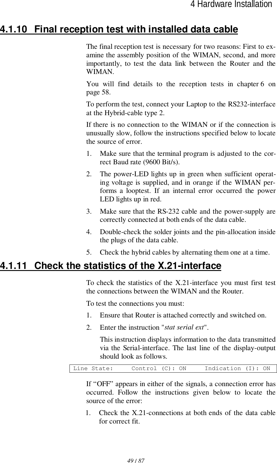
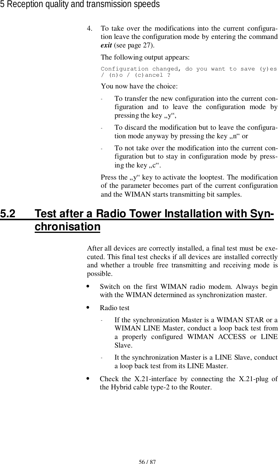
![2 The WIMAN Command Line Level14 / 872.2 PasswordsPasswords serve to protect the WIMAN from unauthorized ac-cess to the command line level in the different authorization lev-els. All passwords must have a length from four to eight char-acters. For the passwords the following characters may be used:" a... z ", " A... z ", " 0... 9 ", " - ", " @ ", "?", " \ ", " [ ", " ] ", "< ", " > ".NOTE:The WIMAN DOES acknowledge case sensitivity characters forpasswords.AttentionTyping in of any other characters than the ones mentioned abovemay lead to a reset of the WIMAN shell.If no password is assigned for the authorization level one, thecommand line appears when the WIMAN is switched on. Oth-erwise you are asked to enter a password to access the commandline level one.A password for authorization level two is always required. Thispassword cannot be deleted, however it is possible to modifythis password.In case of a false configuration or a forgotten password in thelowest authorization level (e.g. user authorization level) quali-fied personnel are needed to access the unit (e.g. Provider). It ispossible to gain access directly to level two by entering the des-ignated password for that level.With suitable instruction (see chapter 3.5.1, on page 40) you canreset the password for authorization level one.If, for any reason, you are unable to arrive at the necessaryauthorization level any longer and you are thus closed out of thedevice, it is possible to gain access with a master password. Themaster password can only be used after the third unsuccessfulaccess attempt and can only be made via the serial interface.Further information on this issue can be obtained from yourWIMAN Distributor.Attention:The input of the master password can be executed exclusivelyover the RS-232 port and results in resetting of all parameters totheir factory settings. A reconfiguration of the device will benecessary afterwards.](https://usermanual.wiki/WIMAN-Systems/WIMAN2A24.Manual01/User-Guide-121124-Page-14.png)
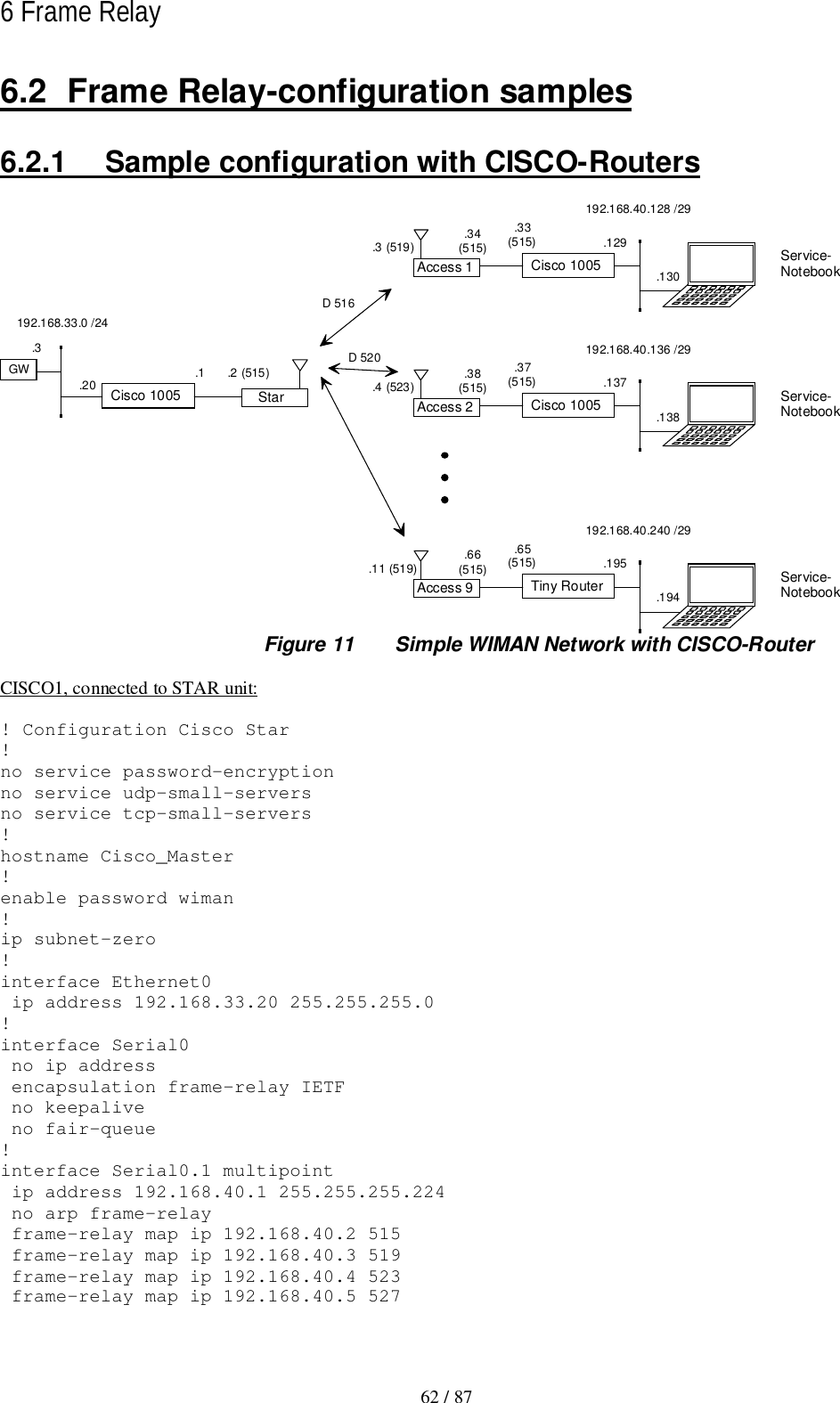
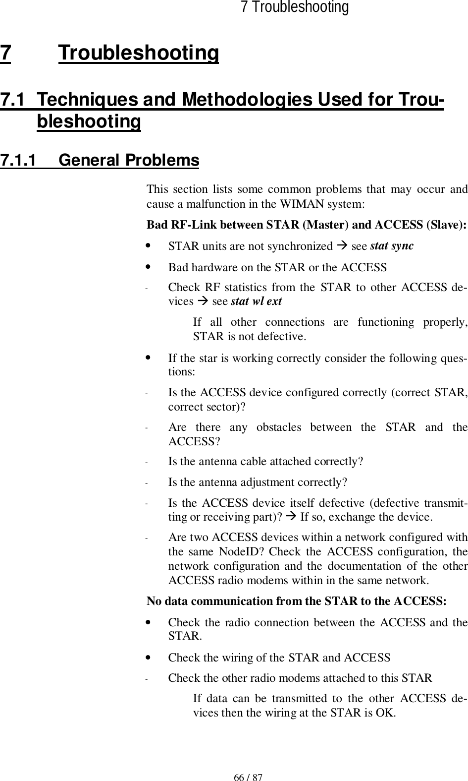
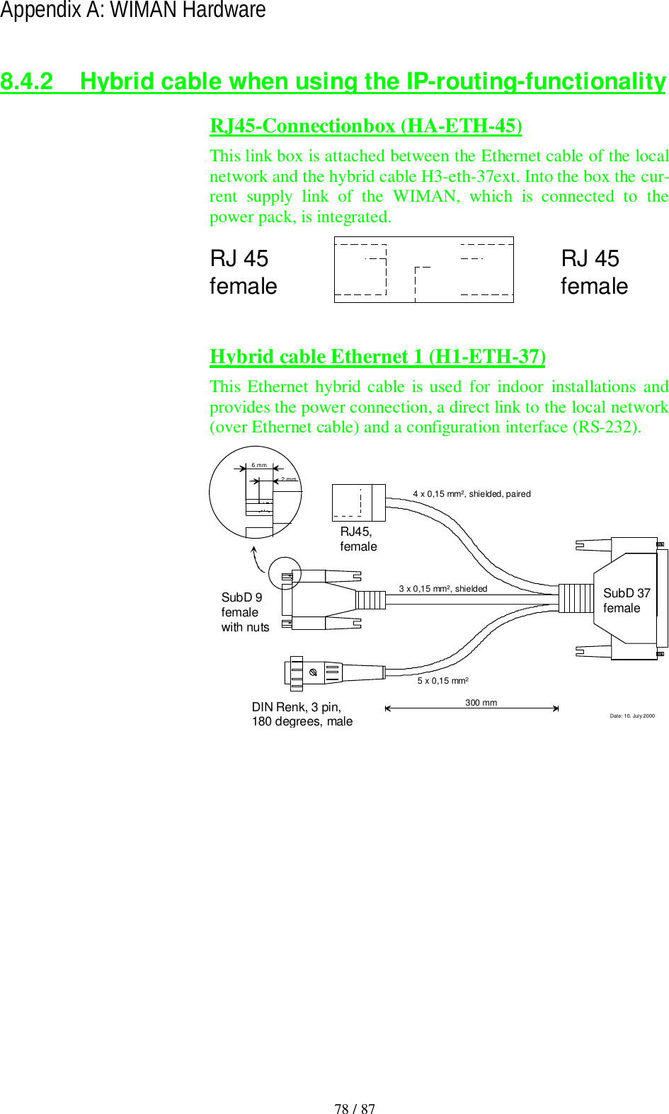
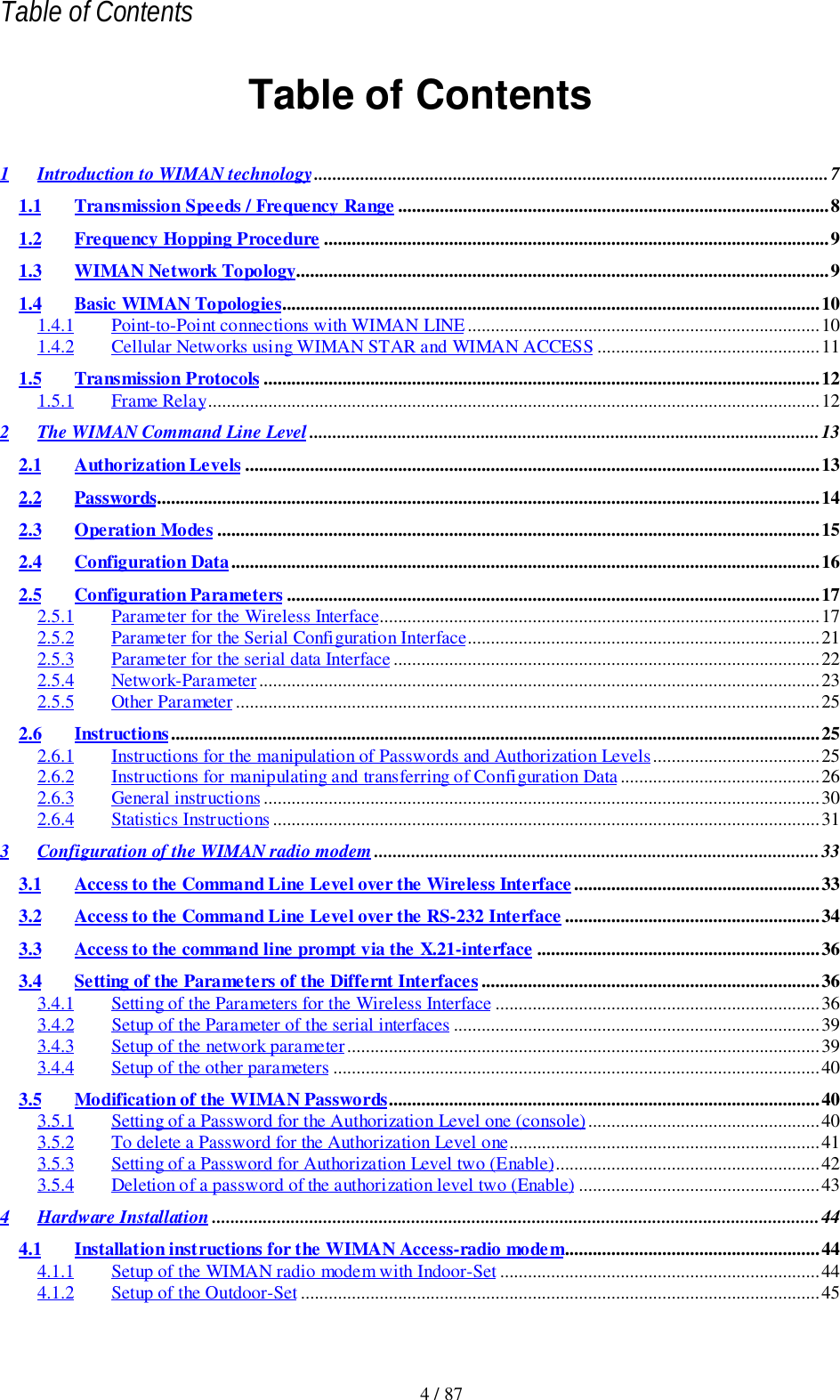
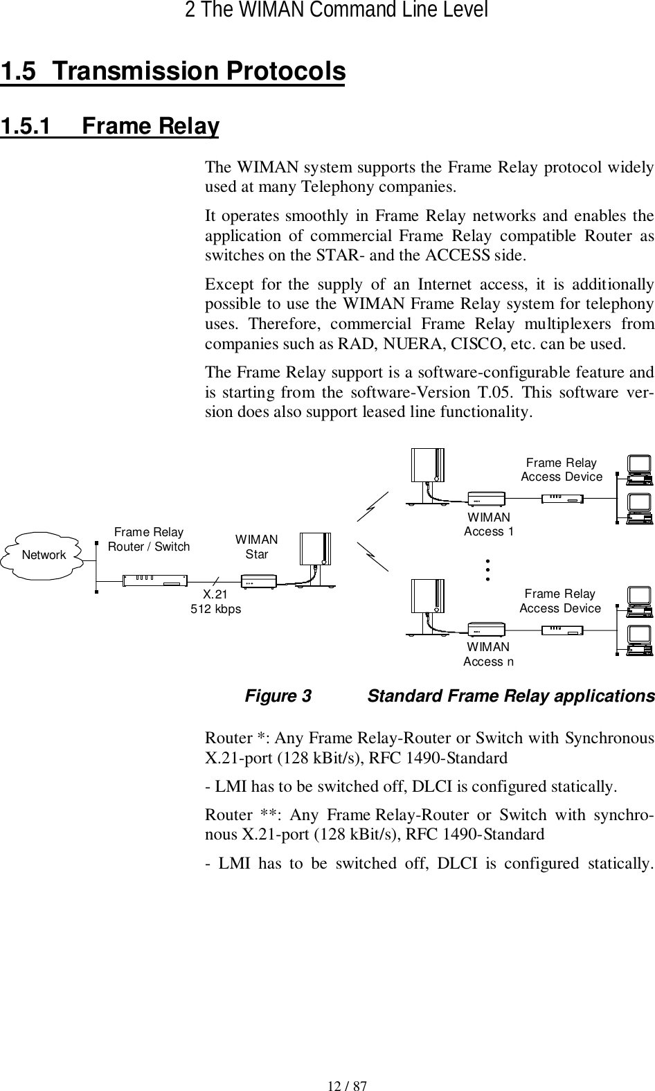
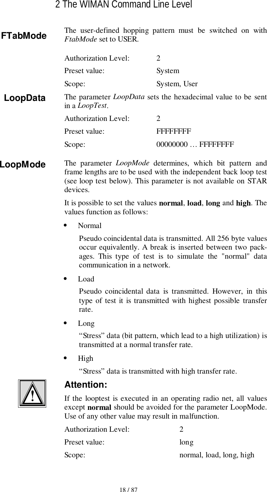
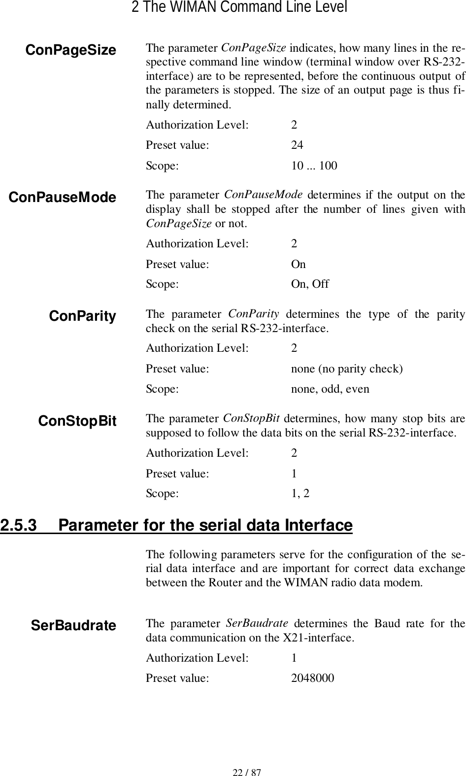
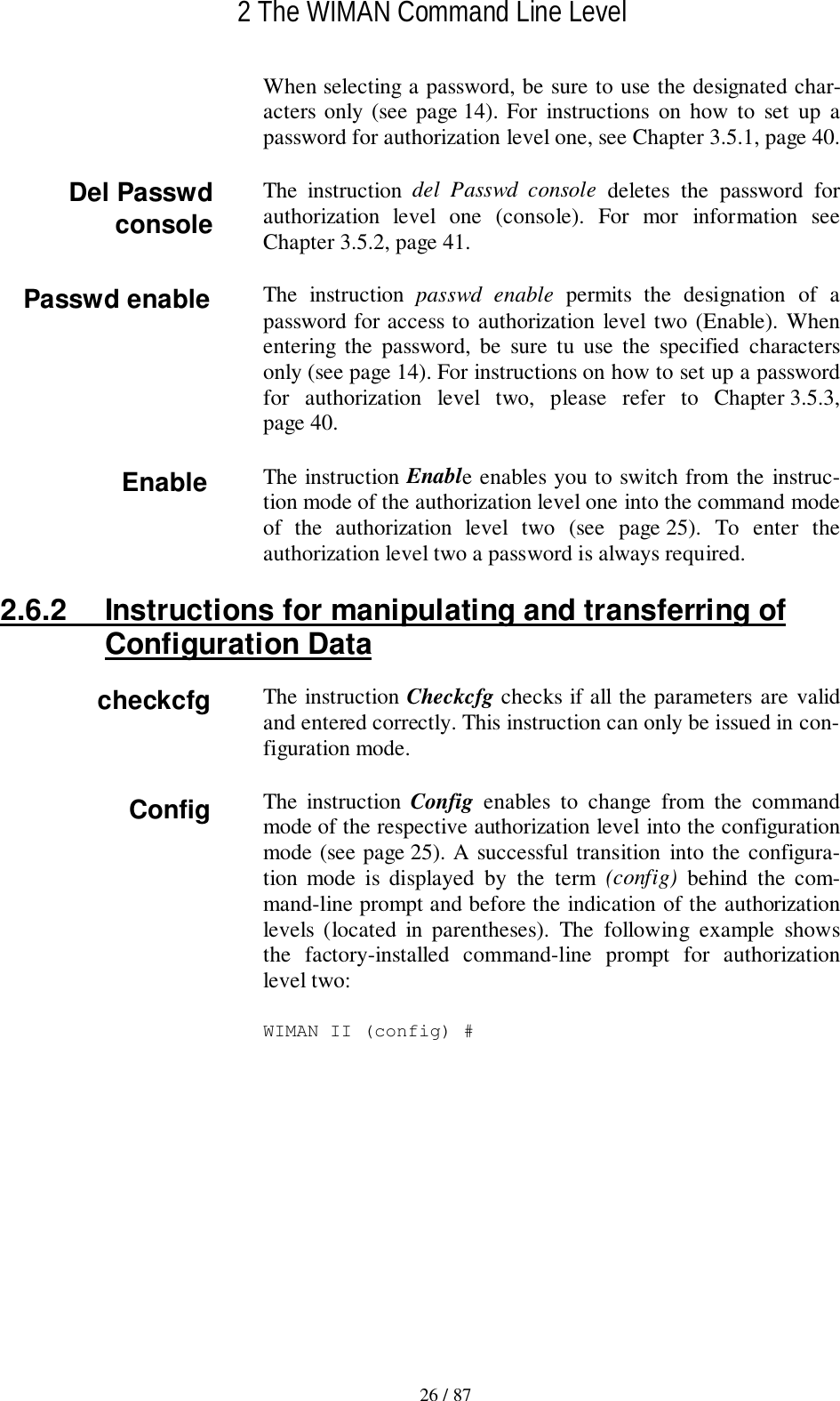
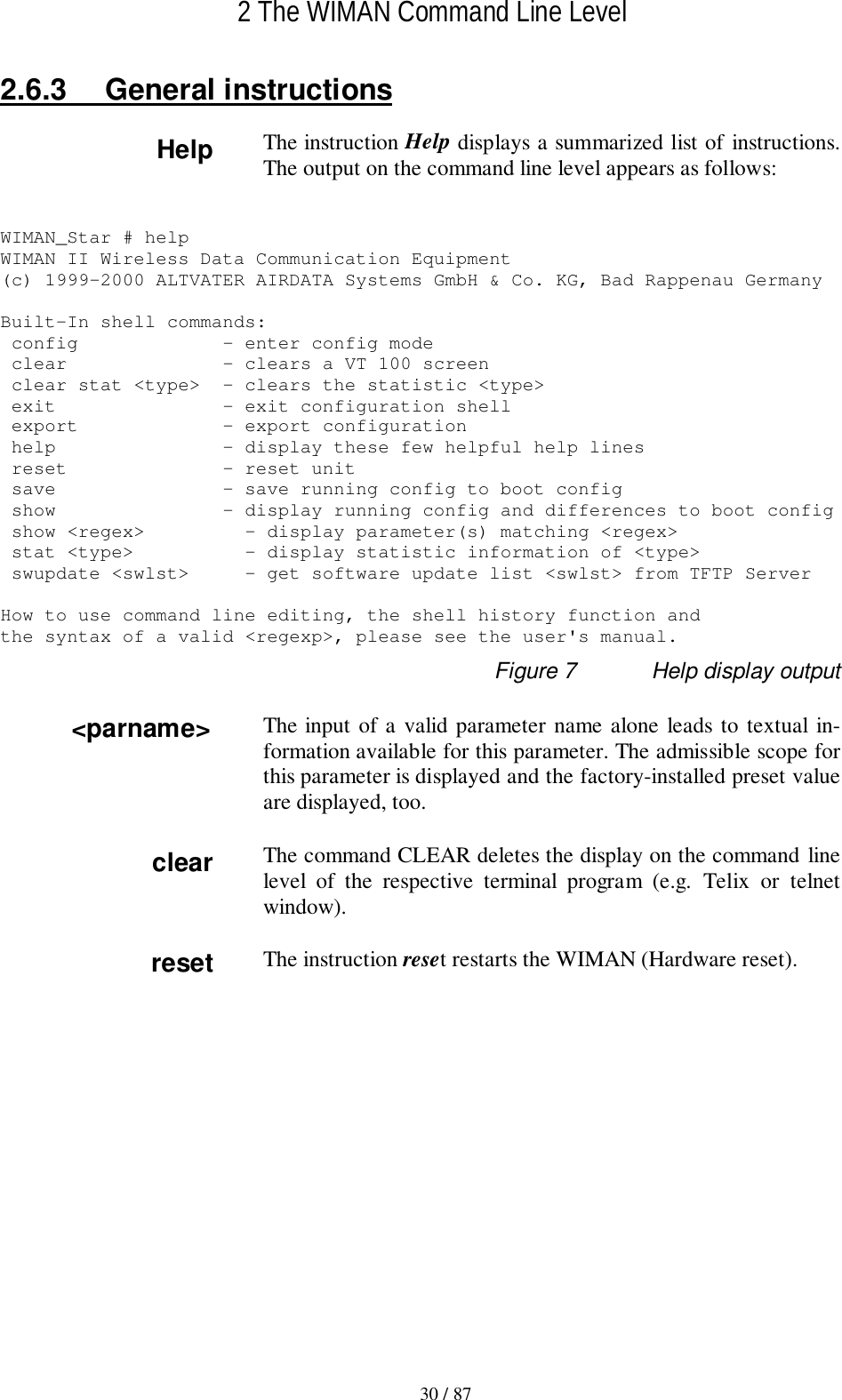
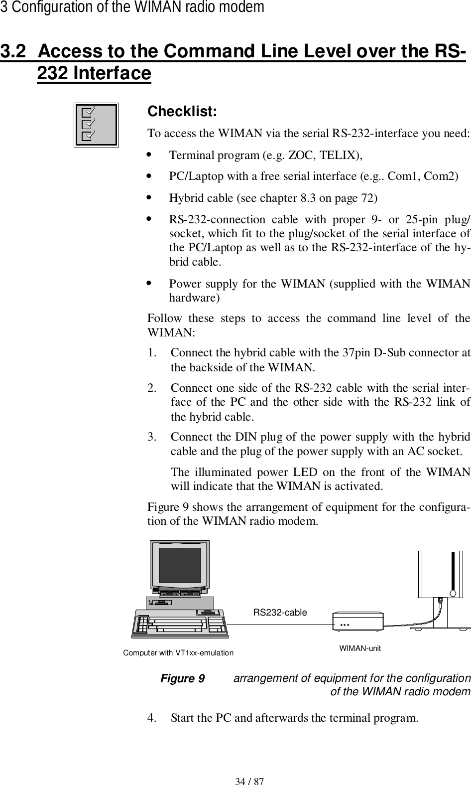
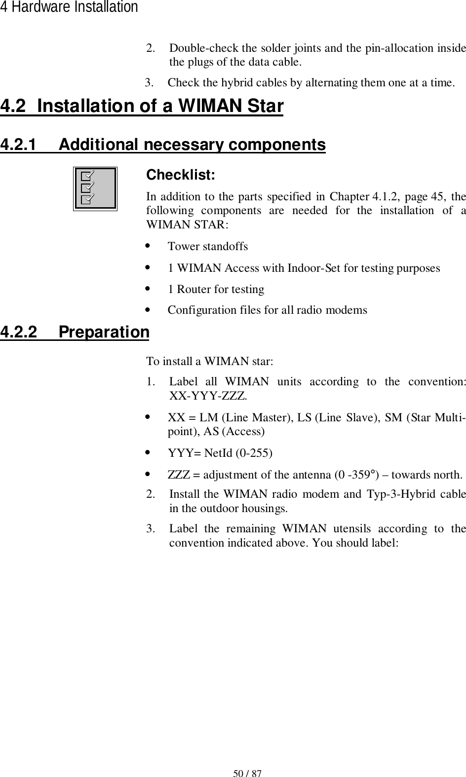
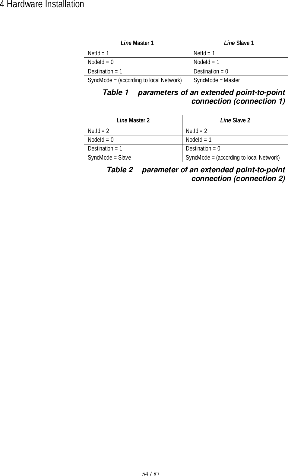
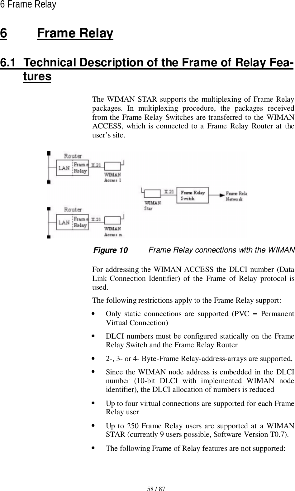
![2 The WIMAN Command Line Level15 / 87l2.3 Operation ModesOn the command line level, the following operating modes aredifferentiated with respect to each authorization level:• Command mode and• Configuration mode.In command mode you can view the accepted parameters of thepresent configuration (current config) as well as give the ac-cepted commands for this mode and authorization level (seeChapter 2.6.1 on page 25).In configuration mode you may change only the parameters al-lowed for that specific authorization level.The system software indicates these parameters as “new con-figuration” (new config). You may render certified instructionsfor this level and this mode.Figure 4 shows how to switch between the different authoriza-tion levels and operation modes. pw password[] optional(n) Authorization levelen enableFigure 4 Diagram of the different operating modesserial connection /TelnetReset pw ←↓ [pw] ↑ exit ↑ exit↓Reset Config ←pw→Command Mode(1) →en pwCommand Mode(2)↓ config ↑ exit ↓ config ↑ exitConfig Mode Config Mode](https://usermanual.wiki/WIMAN-Systems/WIMAN2A24.Manual01/User-Guide-121124-Page-15.png)
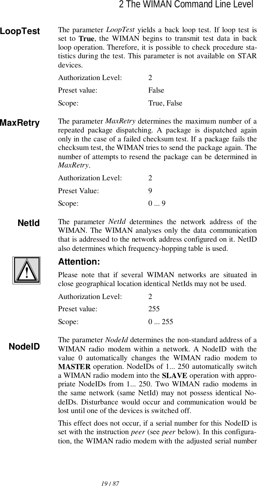
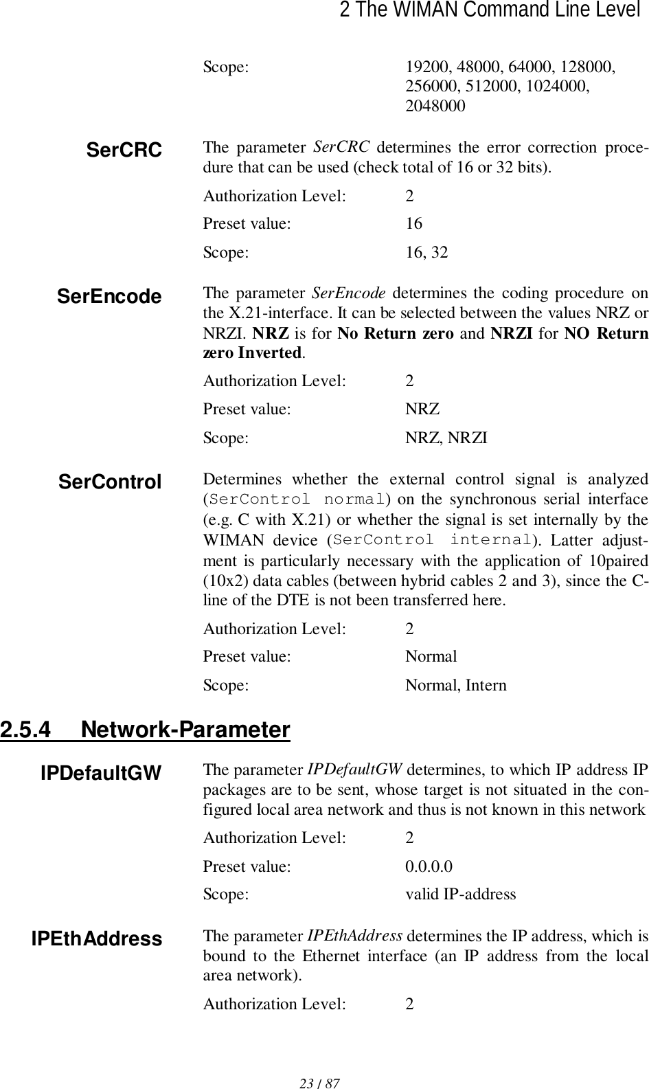
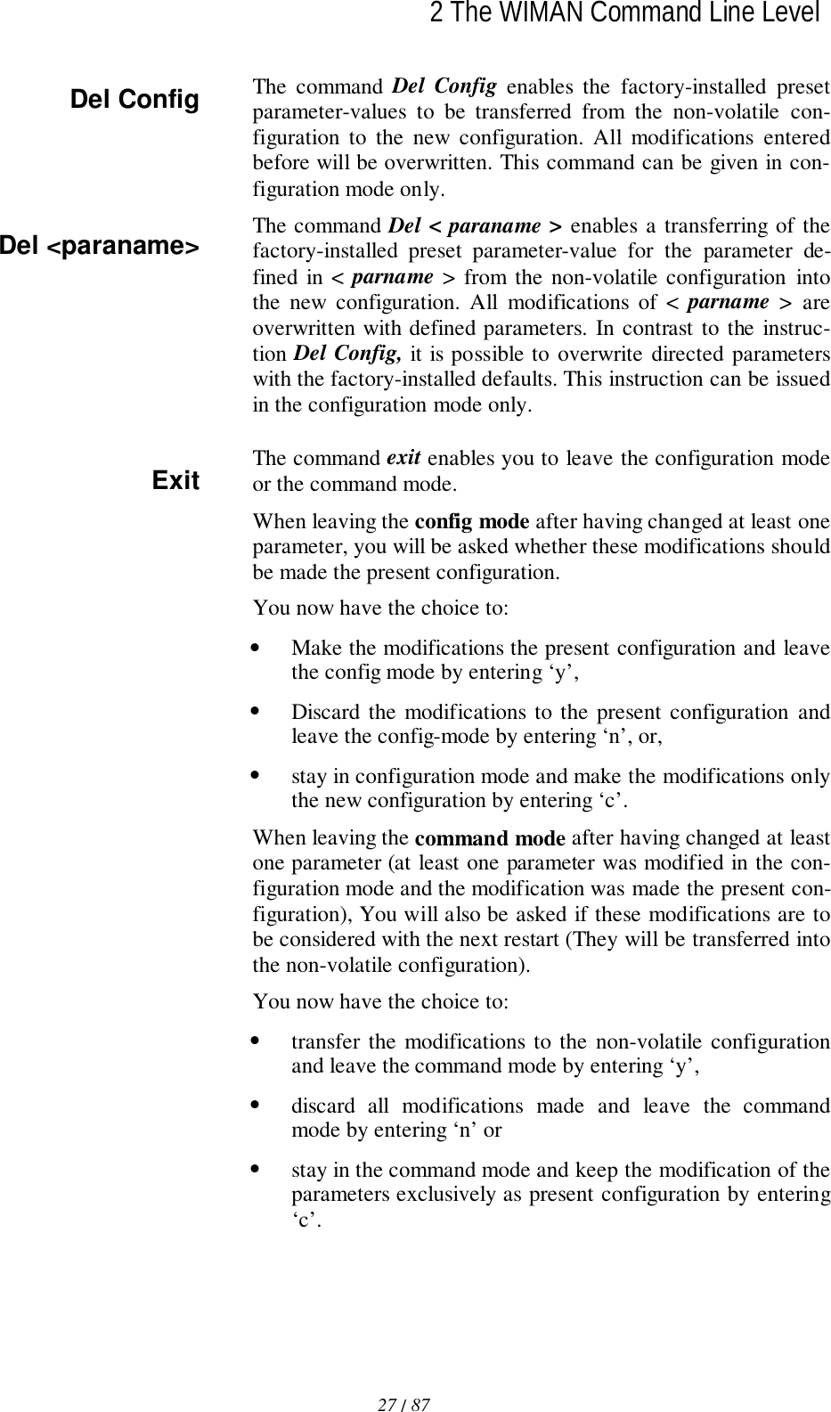
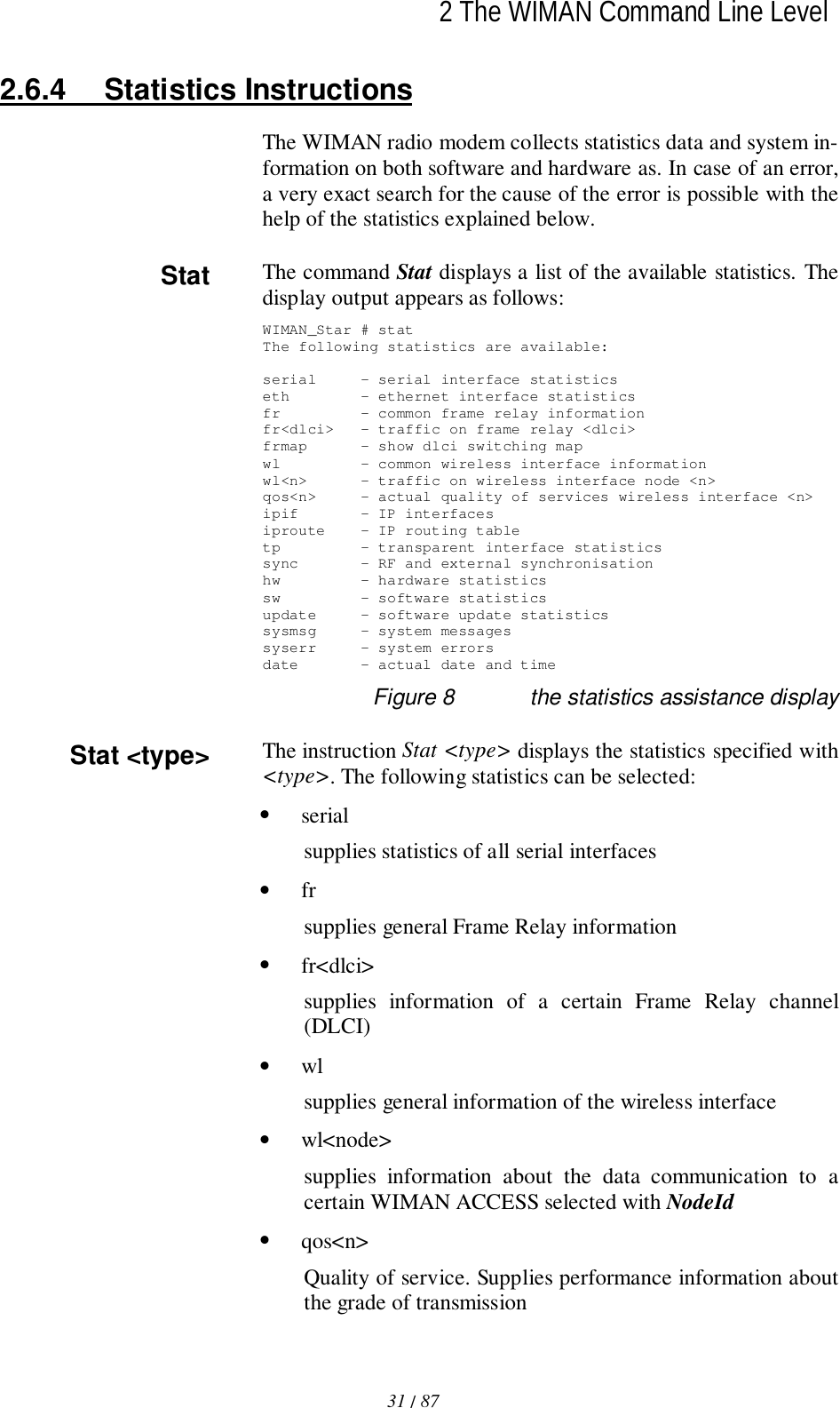
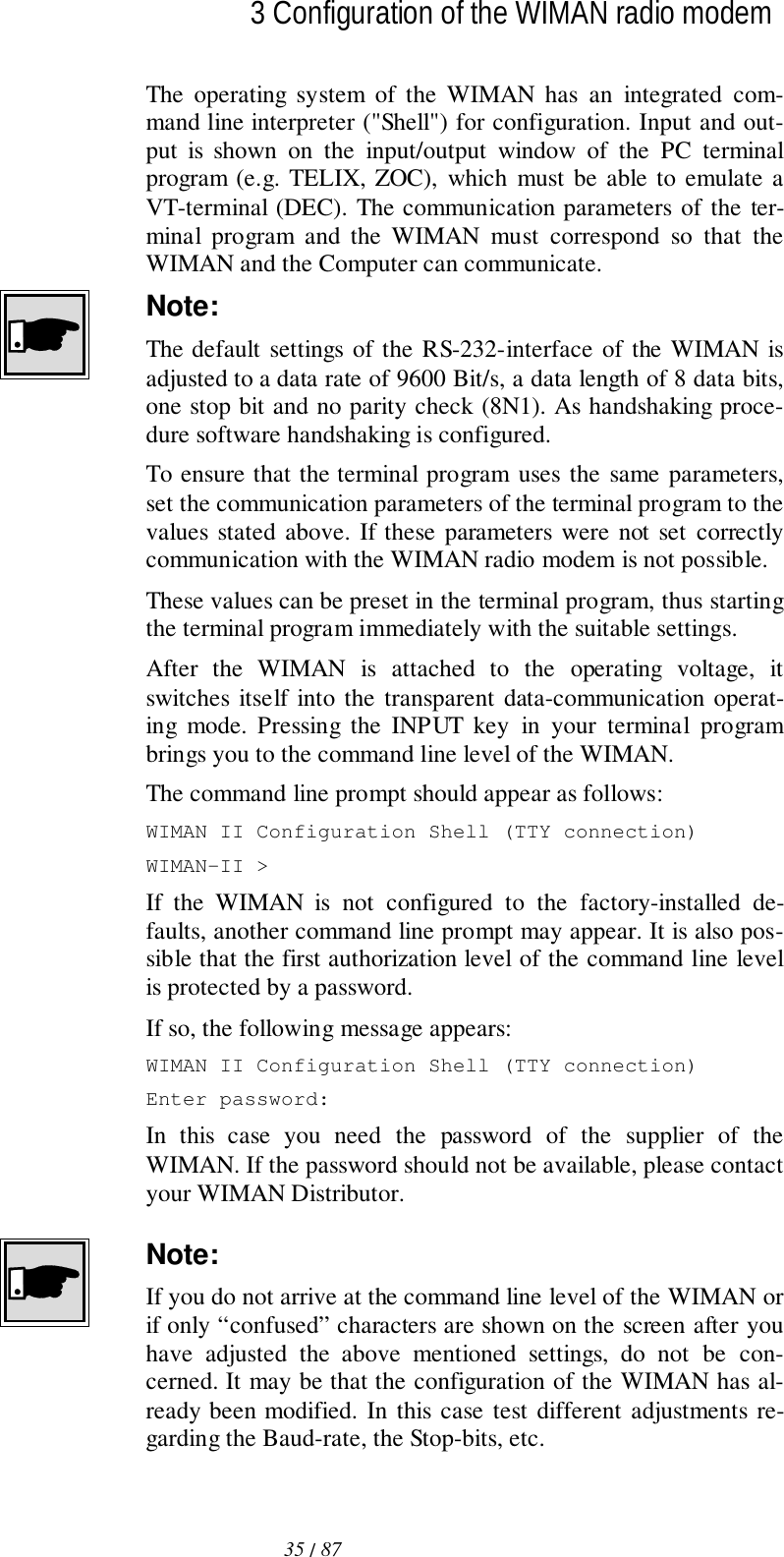
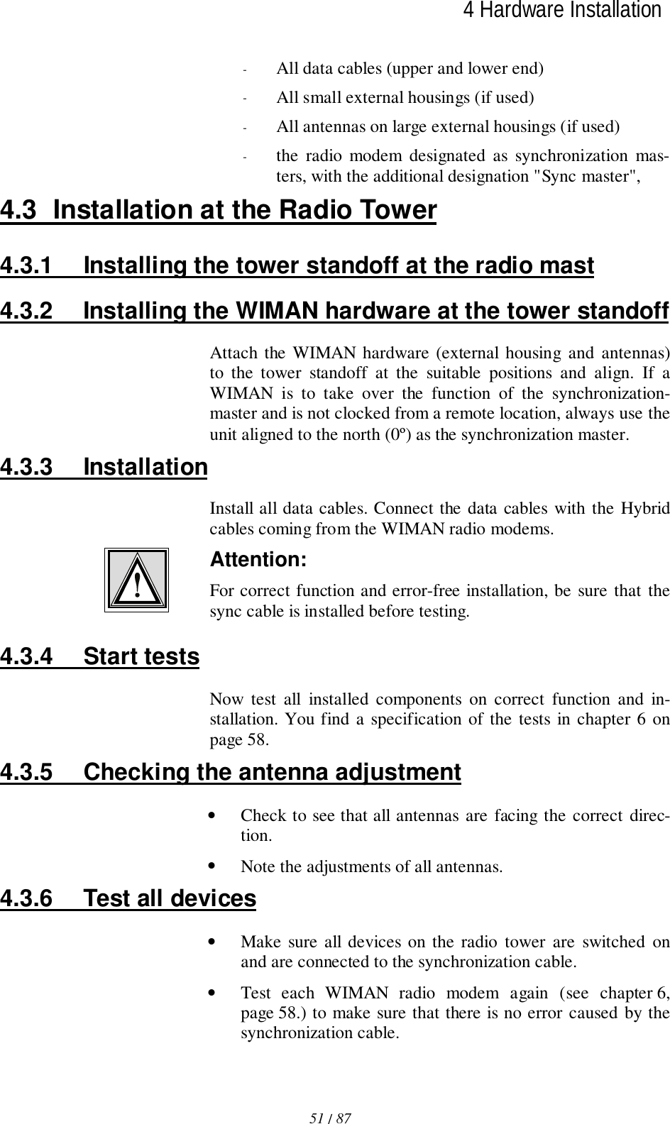
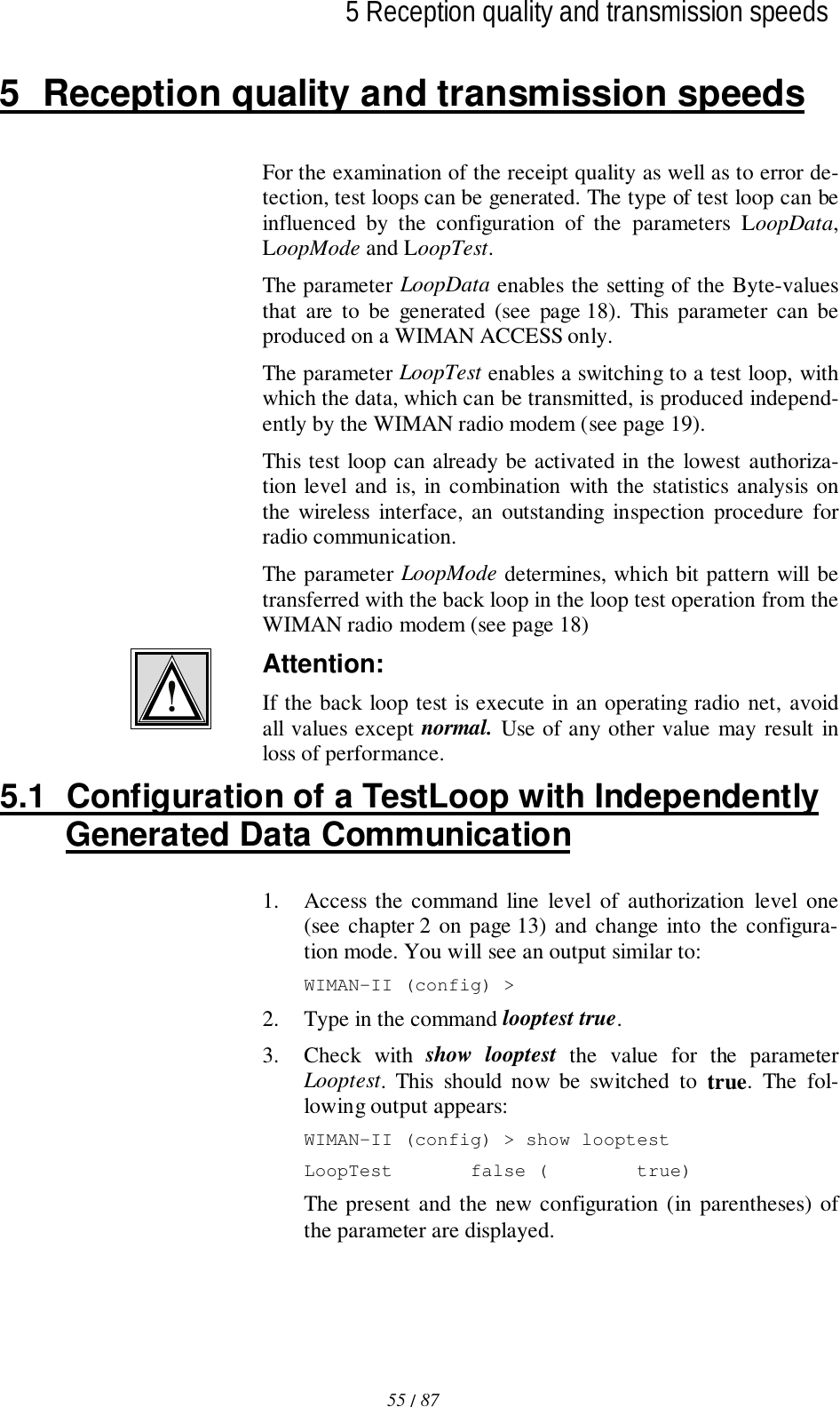
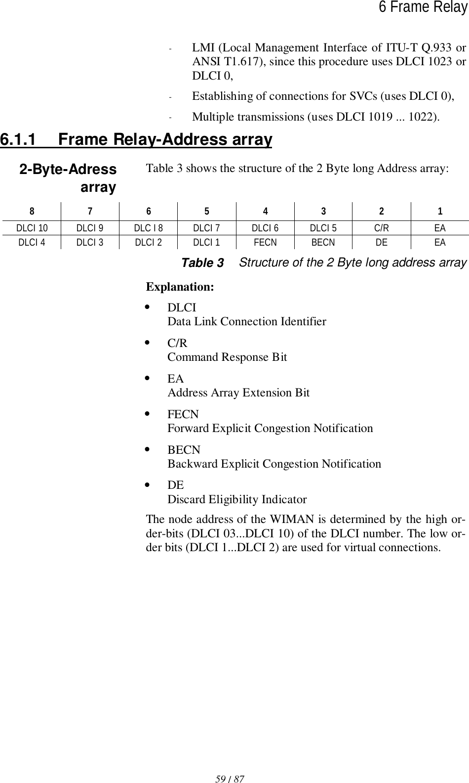
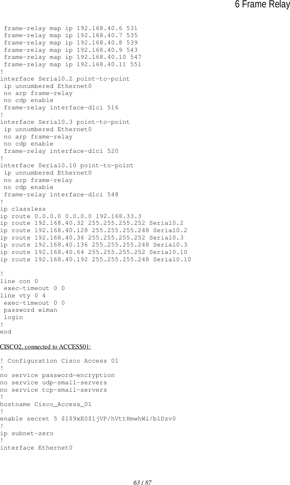
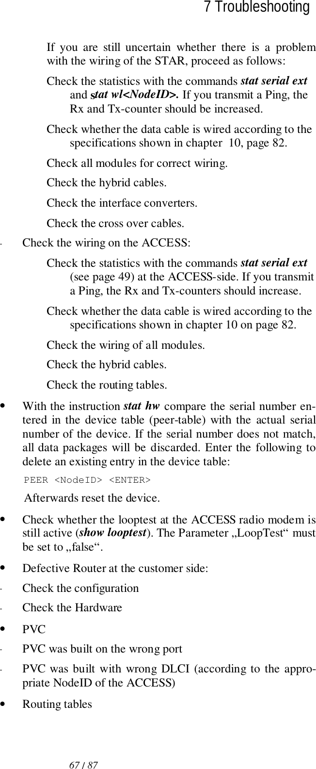
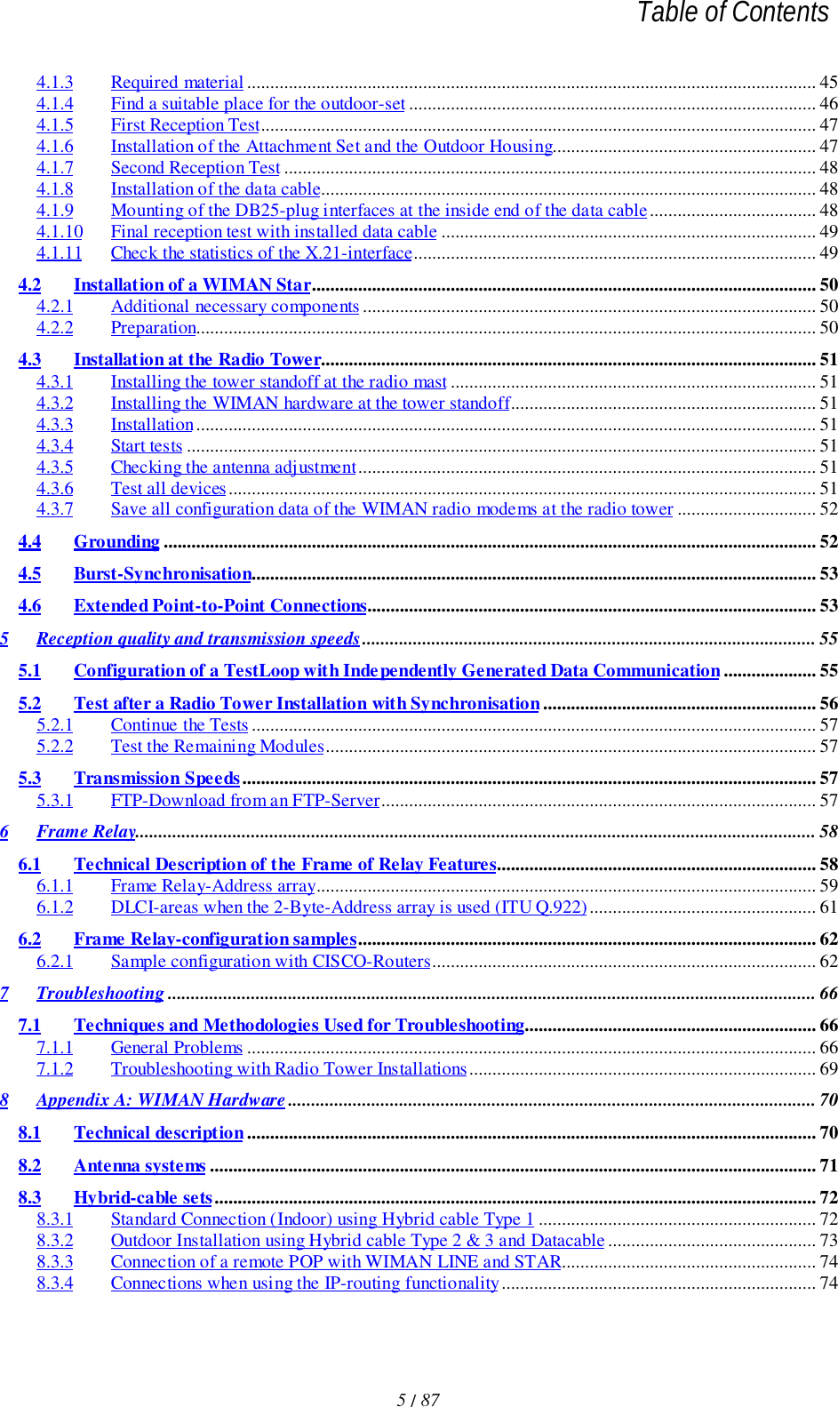
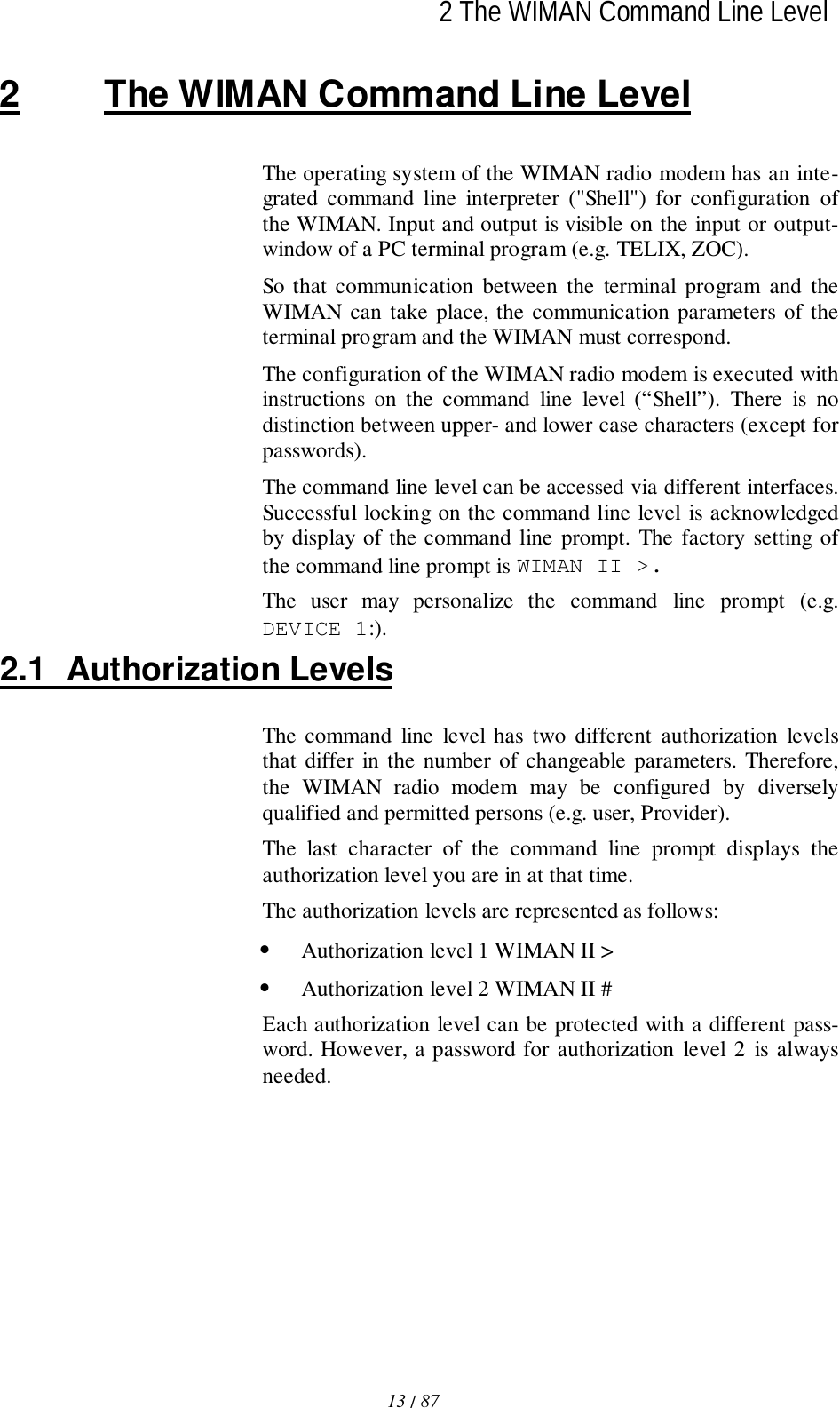
![60 / 876 Frame RelayThe LCI value for the Frame Relay Router of the user is calcu-lated as follows:DLCIm = 512 + NodeId * 4 + m m = [0 ... 3]Table 4 lists the valid DLCI numbers for appropriate node iden-tifiers (NodeId) on use of the 2-Byte-Frame of Relay address ar-ray.WIMAN NodeId DLCI array Note0 512 – 515 reserved (WIMAN STAR)1 516 – 5192 520 – 5233 524 – 5274 528 – 5315 532 – 5356 536 – 5397 540 – 5438 544 – 5479 548 – 55110 552 – 55511 556 – 55912 560 – 56313 564 – 56714 568 – 57115 572 – 575Table 4 NodeId with 2-Byte-Frame Relay address arrayIn the following, the implementation of the Frame of RelayProtocol within the WIMAN software is listed briefly. Exclu-sively the static software-Version of the WIMAN STAR sup-ports the Frame Relay Protocol with the following characteris-tics:• The maximum size of the Frame Relay information fieldamounts to 4096 byte.• The WIMAN star rejects Frame Relay framework with in-valid DLCI number (transmitter and receiver).DLCI valuecalculationFrame Relay-support of theWIMAN Software](https://usermanual.wiki/WIMAN-Systems/WIMAN2A24.Manual01/User-Guide-121124-Page-60.png)