WIMAN Systems WIMAN2A24 FHSS RF Modem User Manual Manual01
WIMAN Systems Inc FHSS RF Modem Manual01
Contents
Manual01
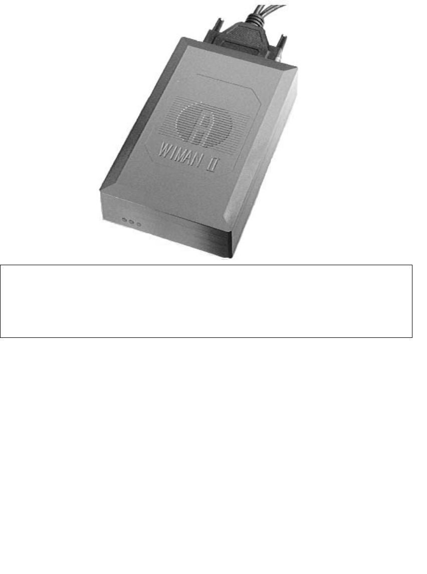
WIMAN Star
WIMAN Access
WIMAN Line
Operation Manual
Software Version: T0.7
- Version E 17 -
August 18th, 2000
ALTVATER AIRDATA Systems GmbH & Co. KG
Riemenstr. 30, 74906 Bad Rappenau
Tel.: 07264/804-0
Fax: 07264/804-209
Email: wiman.support@altvater.com
WWW: http://www.altvater.com
DRAFT

Distribution and/or duplication of any materials belonging to
this product is prohibited except with explicit written permission
from Airdata WIMAN Systems, Inc. All information was gener-
ated after careful research and testing.
Subjects to change without notice.
Bad Rappenau, July 2000
The actual version of this operation manual can be found at
http://www.wiman.net.
Windows is a registered trademark of Microsoft Corporation. Cisco is a
registered trademark of Cisco Systems Inc. Other products mentioned in this
manual might be registered trademarks of the respective manufacturer.
FCC-Information:
FCC ID: NB9WIMAN2A24
This Device complies with Part 15 of the FCC-Rules.
Operation is subject to the following two conditions:
(1) This device may not cause harmful interference, and
(2) This device must accept any interference received,
including interference that may cause undesired operation.
Caution !
Any changes or modifications not in accordance with the instruc-
tions may void the user’s authority to operate the equipment.
The WIMAN unit does not contain any user serviceable parts in-
side and should not be opened by anyone other than authorized
service personnel.
Configuration and installation shall be performed by qualified
personnel only. Improper configuration may void the right to op-
erate WIMAN units. For more information, please refer to chapter
2.5.1 of this manual.
Conventions
This operation manual uses the following conventions:
Symbols:
Danger!
This symbol is intended to warn the user that improper use of
the instruments could result in injury.
Information
This symbol is intended to draw the user’s attention to useful in-
formation.
Note
This symbol is intended to alert the user to information that may
save time or simplify a task.
Attention
This symbol is intended to indicate specific directions and
methods necessary for proper operation.
Checklist
This symbol is intended to inform the user of the required steps
to complete a task.
Texts:
Commands are shown in italics and bold typeface.
Parameters are shown in italics.
Display outputs are shown in Courier.
Keys and names of Menu windows are shown in bold typeface.

Table of Contents
4 / 87
Table of Contents
1 Introduction to WIMAN technology...............................................................................................................7
1.1 Transmission Speeds / Frequency Range .............................................................................................8
1.2 Frequency Hopping Procedure .............................................................................................................9
1.3 WIMAN Network Topology...................................................................................................................9
1.4 Basic WIMAN Topologies....................................................................................................................10
1.4.1 Point-to-Point connections with WIMAN LINE............................................................................10
1.4.2 Cellular Networks using WIMAN STAR and WIMAN ACCESS ................................................11
1.5 Transmission Protocols ........................................................................................................................12
1.5.1 Frame Relay....................................................................................................................................12
2 The WIMAN Command Line Level ..............................................................................................................13
2.1 Authorization Levels ............................................................................................................................13
2.2 Passwords...............................................................................................................................................14
2.3 Operation Modes ..................................................................................................................................15
2.4 Configuration Data...............................................................................................................................16
2.5 Configuration Parameters ...................................................................................................................17
2.5.1 Parameter for the Wireless Interface...............................................................................................17
2.5.2 Parameter for the Serial Configuration Interface............................................................................21
2.5.3 Parameter for the serial data Interface ............................................................................................22
2.5.4 Network-Parameter.........................................................................................................................23
2.5.5 Other Parameter..............................................................................................................................25
2.6 Instructions............................................................................................................................................25
2.6.1 Instructions for the manipulation of Passwords and Authorization Levels....................................25
2.6.2 Instructions for manipulating and transferring of Configuration Data...........................................26
2.6.3 General instructions ........................................................................................................................30
2.6.4 Statistics Instructions ......................................................................................................................31
3 Configuration of the WIMAN radio modem ................................................................................................33
3.1 Access to the Command Line Level over the Wireless Interface.....................................................33
3.2 Access to the Command Line Level over the RS-232 Interface .......................................................34
3.3 Access to the command line prompt via the X.21-interface .............................................................36
3.4 Setting of the Parameters of the Differnt Interfaces .........................................................................36
3.4.1 Setting of the Parameters for the Wireless Interface ......................................................................36
3.4.2 Setup of the Parameter of the serial interfaces ...............................................................................39
3.4.3 Setup of the network parameter......................................................................................................39
3.4.4 Setup of the other parameters .........................................................................................................40
3.5 Modification of the WIMAN Passwords.............................................................................................40
3.5.1 Setting of a Password for the Authorization Level one (console)..................................................40
3.5.2 To delete a Password for the Authorization Level one...................................................................41
3.5.3 Setting of a Password for Authorization Level two (Enable).........................................................42
3.5.4 Deletion of a password of the authorization level two (Enable) ....................................................43
4 Hardware Installation ...................................................................................................................................44
4.1 Installation instructions for the WIMAN Access-radio modem.......................................................44
4.1.1 Setup of the WIMAN radio modem with Indoor-Set .....................................................................44
4.1.2 Setup of the Outdoor-Set ................................................................................................................45

Table of Contents
5 / 87l
4.1.3 Required material ........................................................................................................................... 45
4.1.4 Find a suitable place for the outdoor-set ........................................................................................ 46
4.1.5 First Reception Test........................................................................................................................ 47
4.1.6 Installation of the Attachment Set and the Outdoor Housing......................................................... 47
4.1.7 Second Reception Test ................................................................................................................... 48
4.1.8 Installation of the data cable........................................................................................................... 48
4.1.9 Mounting of the DB25-plug interfaces at the inside end of the data cable.................................... 48
4.1.10 Final reception test with installed data cable ................................................................................. 49
4.1.11 Check the statistics of the X.21-interface....................................................................................... 49
4.2 Installation of a WIMAN Star............................................................................................................. 50
4.2.1 Additional necessary components.................................................................................................. 50
4.2.2 Preparation...................................................................................................................................... 50
4.3 Installation at the Radio Tower........................................................................................................... 51
4.3.1 Installing the tower standoff at the radio mast............................................................................... 51
4.3.2 Installing the WIMAN hardware at the tower standoff.................................................................. 51
4.3.3 Installation...................................................................................................................................... 51
4.3.4 Start tests ........................................................................................................................................ 51
4.3.5 Checking the antenna adjustment................................................................................................... 51
4.3.6 Test all devices............................................................................................................................... 51
4.3.7 Save all configuration data of the WIMAN radio modems at the radio tower .............................. 52
4.4 Grounding ............................................................................................................................................. 52
4.5 Burst-Synchronisation.......................................................................................................................... 53
4.6 Extended Point-to-Point Connections................................................................................................. 53
5 Reception quality and transmission speeds.................................................................................................. 55
5.1 Configuration of a TestLoop with Independently Generated Data Communication.................... 55
5.2 Test after a Radio Tower Installation with Synchronisation........................................................... 56
5.2.1 Continue the Tests .......................................................................................................................... 57
5.2.2 Test the Remaining Modules.......................................................................................................... 57
5.3 Transmission Speeds............................................................................................................................ 57
5.3.1 FTP-Download from an FTP-Server.............................................................................................. 57
6 Frame Relay................................................................................................................................................... 58
6.1 Technical Description of the Frame of Relay Features..................................................................... 58
6.1.1 Frame Relay-Address array............................................................................................................ 59
6.1.2 DLCI-areas when the 2-Byte-Address array is used (ITU Q.922)................................................. 61
6.2 Frame Relay-configuration samples................................................................................................... 62
6.2.1 Sample configuration with CISCO-Routers................................................................................... 62
7 Troubleshooting ............................................................................................................................................ 66
7.1 Techniques and Methodologies Used for Troubleshooting............................................................... 66
7.1.1 General Problems ........................................................................................................................... 66
7.1.2 Troubleshooting with Radio Tower Installations........................................................................... 69
8 Appendix A: WIMAN Hardware.................................................................................................................. 70
8.1 Technical description........................................................................................................................... 70
8.2 Antenna systems ................................................................................................................................... 71
8.3 Hybrid-cable sets.................................................................................................................................. 72
8.3.1 Standard Connection (Indoor) using Hybrid cable Type 1 ............................................................ 72
8.3.2 Outdoor Installation using Hybrid cable Type 2 & 3 and Datacable ............................................. 73
8.3.3 Connection of a remote POP with WIMAN LINE and STAR....................................................... 74
8.3.4 Connections when using the IP-routing functionality.................................................................... 74

Table of Contents
6 / 87
8.4 Hybridcable...........................................................................................................................................75
8.4.1 Hybridcable used for X21-configurations ......................................................................................75
8.4.2 Hybrid cable when using the IP-routing-functionality...................................................................78
9 Appendix B: Technical data..........................................................................................................................80
10 Appendix C: Pin-allocation of the Datacables.........................................................................................82
10.1 WIMAN Datacable (10 x 2) .................................................................................................................82
10.2 WIMAN Datacable (12 x 2) .................................................................................................................83
11 Appendix D: Alphabetical list of instructions...........................................................................................84
12 Index...........................................................................................................................................................85
13 Index of figures..........................................................................................................................................86
14 Index of tables............................................................................................................................................87

2 The WIMAN Command Line Level
7 / 87l
1 Introduction to WIMAN technology
The WIMAN product series provides a powerful new technol-
ogy for the design of flexible data networks. Integrating a mul-
titude of innovative and optimized methods and communication
protocols, we’ve created a wireless network technology, which
is available for various applications such as campus networking,
high speed access for Internet users, and cellular data networks
in conurbation areas, etc.
In contrast to other available wireless products, the WIMAN
product line integrates the demand for an economic system with
high data rates, a high range and efficient utilization of the fre-
quency-spectrum. The WIMAN System utilizes the most mod-
ern spread spectrum technology without using any further en-
coding algorithm, and features higher security and noise immu-
nity than other existing systems. Applying the frequency hop-
ping technique in combination with an intelligent transmission
control algorithm, the ISM frequency range between 2.4 and
2.4835 GHz is optimally used.
The interfaces provided by the WIMAN unit to attach to the
customer's terminal equipment complies with the international
X.21 and V.24/RS232/RJ45 standards allowing a direct connec-
tion to any standard personal computer, workstation or main-
frame system. For hooking up wired networks (LAN, MAN,
WAN), there are various routers available in the form of hard-
ware or software solutions.
The WIMAN product line provides users with the benefits of
high performance and speed in a wireless modem. WIMAN is
easily distinguished from other transmission systems through
several remarkable features:

2 The WIMAN Command Line Level
8 / 87
1.1 Transmission Speeds / Frequency Range
At present, wireless data network technology can be divided into
two categories: The first category consists of wireless modems
with a small transmission bandwidth. These products are used
for company networks, cellular networks, CDPD (Cellular
Digital Packed Data) or GSM (Global System for Mobile com-
munication) networks. The second category consists of wireless
modems with large bandwidth in the ISM range (Industrial Sci-
entific Media, frequency range around 2,4 GHz), such as wire-
less LAN products.
It is possible to cover a large area with the narrow band systems.
Some systems are even able to cover a complete country. The
other LAN products specified above operate with substantially
higher data transmission rates; however, the range of these sys-
tems is limited to approx. 300m/900ft. Therefore, the area of ap-
plication is strongly reduced.
The WIMAN technology offers the advantages of both the nar-
row band systems and the broadband systems. With a clear line
of sight between the antennas, data can be transmitted between
two WIMAN radio modems with a rate of up to 2048 KBit/s (at
the data interface) / 512KBit/sec at the wireless interface in du-
plex operation over a distance of up to approx. 40km/25miles
(FCC version) or up to approx. 5km/3.2miles (ETSI version).
Furthermore, WIMAN systems are deployed in a highly scalable
manner similar in nature to a cellular structure. Therefore, it can
overcome some of the need for direct line-of-sight.

2 The WIMAN Command Line Level
9 / 87l
1.2 Frequency Hopping Procedure
All WIMAN radio modems operate with the modern frequency
hopping procedure. With this procedure, the RF-channel is
changed in very short intervals (all 8 ms). A total of 80 non-
overlapping radio channels are available.
WIMAN takes advantage of these 80 channels, each with 1
MHz of bandwidth, by use of spread spectrum technology (fre-
quency hopping).
The WIMAN radio modem transmits information packages that
hop from one frequency to another, not staying longer than 8 ms
in a frequency range.
As data packets are transmitted and received, the ISP selects the
order of the channels, producing a truly secured line of data.
This remarkable feature yields the following important advan-
tages:
• High security against eavesdropping due to fast changes
of the channel,
• Resistance to jamming,
• Protection against other RF-systems in the same fre-
quency band,
• High performance with high efficiency,
• Possibility of parallel operation of WIMAN connections
by use of different frequency-hopping patterns.
1.3 WIMAN Network Topology
With the WIMAN technology, bonding can be structured in a
simple point-to-point connection, but it is also possible to set up
various other network topologies. The WIMAN product series
consists of three different wireless WIMAN radio-modems:
WIMAN STAR: wireless base station for public and private
point-to-multi-point networks.
WIMAN ACCESS: wireless access node for public and private
point-to-multi-point networks,
WIMAN LINE: wireless point-to-point connection between
two computers or computer networks.
2 The WIMAN Command Line Level
10 / 87
1.4 Basic WIMAN Topologies
As previously mentioned, the WIMAN technology is not limited
to point-to-point connections. Different network topologies can
be structured. The following chapter introduces some simple
network configurations using the WIMAN units to illustrate
some of the features of each configuration.
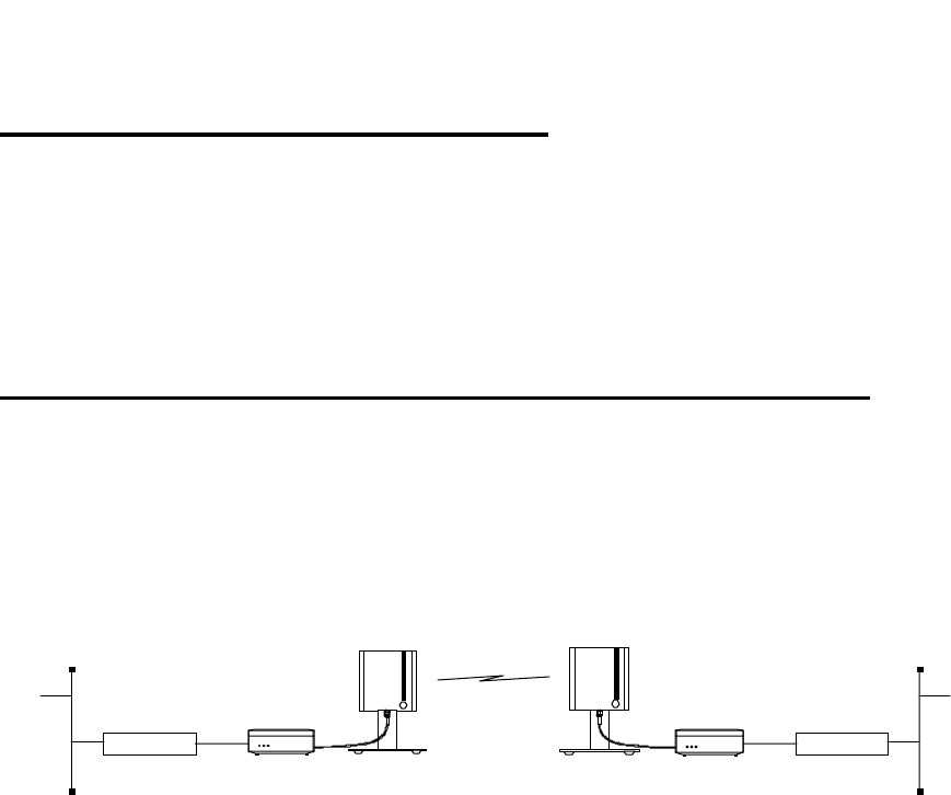
1.4.1 Point-to-Point connections with WIMAN LINE
WIMAN LINE radio modems enable point-to-point connections
between local area networks, data terminals or individual per-
sonal computers. In general, the WIMAN LINE can replace a
wire communication or a zero-modem cable. At present the
WIMAN LINE supports duplex data transmission rates of 256
kBit/s at 2FSK
WIMAN Line
Router WIMAN Line Router
Figure 1 Point-to-Point connection using WIMAN LINE
2 The WIMAN Command Line Level
11 / 87l
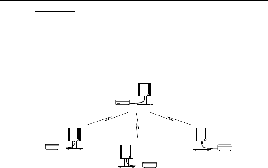
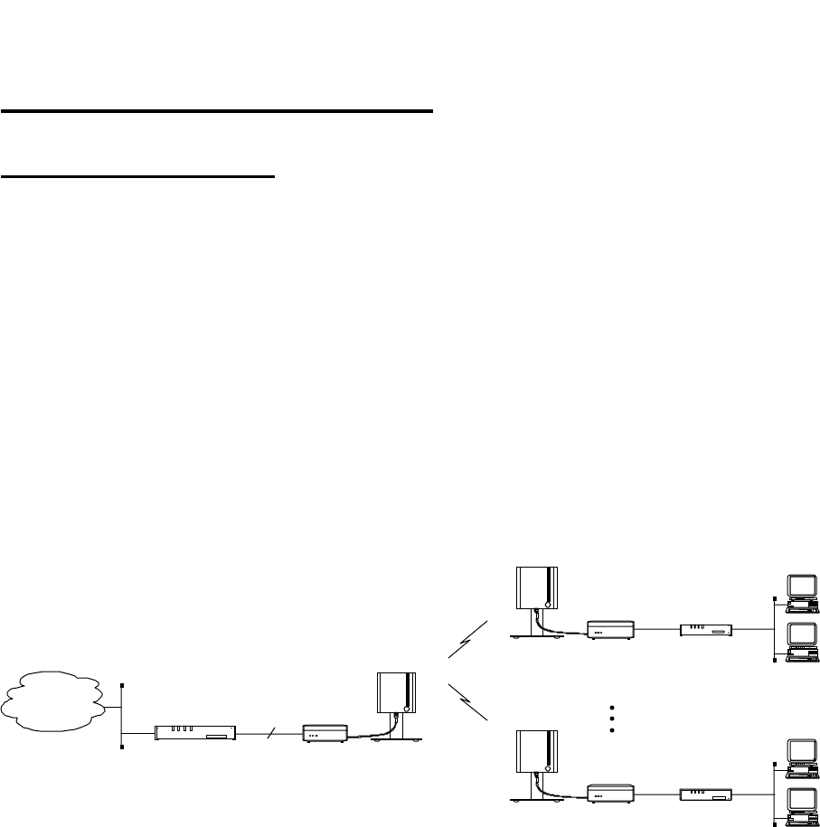
1.4.2 Cellular Networks using WIMAN STAR and WIMAN
ACCESS
One of the outstanding features of the WIMAN series is its abil-
ity to support point-to-multi-point networks with technically
matured distribution of load between the individual ACCESS
devices (load balancing).
Figure 2 shows a typical network environment.
WIMAN
Access
WIMAN
Star
WIMAN
Access
WIMAN
Access
Figure 2 wireless access networks with WIMAN STAR
and WIMAN ACCESS
This network configuration can be used as a wireless connection
to the Internet.
The current software-Version supports up to 9 WIMAN
ACCESS per WIMAN STAR. They can be configured to meet
higher density of traffic in the networks by use of several syn-
chronized parallel WIMAN radio modems.
Avoid errors by synchronization of the WIMAN units (see
chapter 4.5 on page 53).
2 The WIMAN Command Line Level
12 / 87
1.5 Transmission Protocols
1.5.1 Frame Relay
The WIMAN system supports the Frame Relay protocol widely
used at many Telephony companies.
It operates smoothly in Frame Relay networks and enables the
application of commercial Frame Relay compatible Router as
switches on the STAR- and the ACCESS side.
Except for the supply of an Internet access, it is additionally
possible to use the WIMAN Frame Relay system for telephony
uses. Therefore, commercial Frame Relay multiplexers from
companies such as RAD, NUERA, CISCO, etc. can be used.
The Frame Relay support is a software-configurable feature and
is starting from the software-Version T.05. This software ver-
sion does also support leased line functionality.
Frame Relay
Router / Switch
Network
WIMAN
Access 1
WIMAN
Star
WIMAN
Access n
Frame Relay
Access Device
Frame Relay
Access Device
X.21
512 kbps
Figure 3 Standard Frame Relay applications
Router *: Any Frame Relay-Router or Switch with Synchronous
X.21-port (128 kBit/s), RFC 1490-Standard
- LMI has to be switched off, DLCI is configured statically.
Router **: Any Frame Relay-Router or Switch with synchro-
nous X.21-port (128 kBit/s), RFC 1490-Standard
- LMI has to be switched off, DLCI is configured statically.

2 The WIMAN Command Line Level
13 / 87l
2 The WIMAN Command Line Level
The operating system of the WIMAN radio modem has an inte-
grated command line interpreter ("Shell") for configuration of
the WIMAN. Input and output is visible on the input or output-
window of a PC terminal program (e.g. TELIX, ZOC).
So that communication between the terminal program and the
WIMAN can take place, the communication parameters of the
terminal program and the WIMAN must correspond.
The configuration of the WIMAN radio modem is executed with
instructions on the command line level (“Shell”). There is no
distinction between upper- and lower case characters (except for
passwords).
The command line level can be accessed via different interfaces.
Successful locking on the command line level is acknowledged
by display of the command line prompt. The factory setting of
the command line prompt is WIMAN II >.
The user may personalize the command line prompt (e.g.
DEVICE 1:).
2.1 Authorization Levels
The command line level has two different authorization levels
that differ in the number of changeable parameters. Therefore,
the WIMAN radio modem may be configured by diversely
qualified and permitted persons (e.g. user, Provider).
The last character of the command line prompt displays the
authorization level you are in at that time.
The authorization levels are represented as follows:
• Authorization level 1 WIMAN II >
• Authorization level 2 WIMAN II #
Each authorization level can be protected with a different pass-
word. However, a password for authorization level 2 is always
needed.
2 The WIMAN Command Line Level
14 / 87
2.2 Passwords
Passwords serve to protect the WIMAN from unauthorized ac-
cess to the command line level in the different authorization lev-
els. All passwords must have a length from four to eight char-
acters. For the passwords the following characters may be used:
" a... z ", " A... z ", " 0... 9 ", " - ", " @ ", "?", " \ ", " [ ", " ] ", "
< ", " > ".
NOTE:
The WIMAN DOES acknowledge case sensitivity characters for
passwords.
Attention
Typing in of any other characters than the ones mentioned above
may lead to a reset of the WIMAN shell.
If no password is assigned for the authorization level one, the
command line appears when the WIMAN is switched on. Oth-
erwise you are asked to enter a password to access the command
line level one.
A password for authorization level two is always required. This
password cannot be deleted, however it is possible to modify
this password.
In case of a false configuration or a forgotten password in the
lowest authorization level (e.g. user authorization level) quali-
fied personnel are needed to access the unit (e.g. Provider). It is
possible to gain access directly to level two by entering the des-
ignated password for that level.
With suitable instruction (see chapter 3.5.1, on page 40) you can
reset the password for authorization level one.
If, for any reason, you are unable to arrive at the necessary
authorization level any longer and you are thus closed out of the
device, it is possible to gain access with a master password. The
master password can only be used after the third unsuccessful
access attempt and can only be made via the serial interface.
Further information on this issue can be obtained from your
WIMAN Distributor.
Attention:
The input of the master password can be executed exclusively
over the RS-232 port and results in resetting of all parameters to
their factory settings. A reconfiguration of the device will be
necessary afterwards.

2 The WIMAN Command Line Level
15 / 87l
2.3 Operation Modes
On the command line level, the following operating modes are
differentiated with respect to each authorization level:
• Command mode and
• Configuration mode.
In command mode you can view the accepted parameters of the
present configuration (current config) as well as give the ac-
cepted commands for this mode and authorization level (see
Chapter 2.6.1 on page 25).
In configuration mode you may change only the parameters al-
lowed for that specific authorization level.
The system software indicates these parameters as “new con-
figuration” (new config). You may render certified instructions
for this level and this mode.
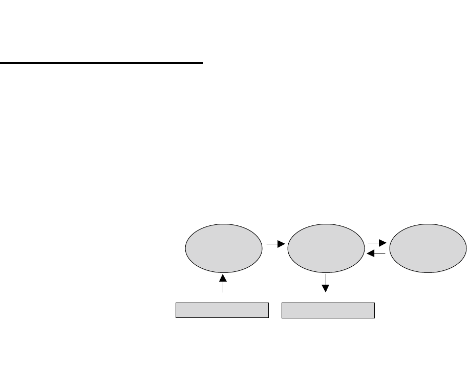
Figure 4 shows how to switch between the different authoriza-
tion levels and operation modes.
pw password
[] optional
(n) Authorization level
en enable
Figure 4 Diagram of the different operating modes
serial connection /
Telnet
Reset pw ←↓ [pw] ↑ exit ↑ exit
↓
Reset Config ←
pw
→
Command Mode
(1) →
en pw
Command Mode
(2)
↓ config ↑ exit ↓ config ↑ exit
Config Mode Config Mode
2 The WIMAN Command Line Level
16 / 87
2.4 Configuration Data
The configuration data (values of the adjustable parameters) is
classified into the following three types:
• New configuration (new config),
• Present configuration (current config) and
• Non-volatile configuration (boot config).
Figure 5 shows the connections of the three different types of
configuration data.
The new configuration is created by modification of the pa-
rameters in the configuration mode (see Chapter 2). This has no
effect on the current operation. It is possible to produce a new
configuration by manually changing the parameters or by read-
ing-in a parameter text file. In the parameter text file comments
may be inserted at the start of a line or after an instruction (See
Chapter xxx on page xxx).
The present configuration consists of the parameters used by
the system at that time. This configuration can be saved as a text
file.
The non-volatile configuration consists of the parameters
called on and made the present configuration at a strat or restart
of the device. Modified parameters (new configuration) can ei-
ther be taken over (transfer for present configuration) or rejected
by a query when leaving the configuration mode.
The up-to-date parameters (present configuration) can be per-
manently taken over by a further query when leaving the com-
mand mode (transfer into the non-volatile configuration) or
maintained only up to the next restart.
ASCII- command-file ASCII- configuration file
(new config) (current config) (boot config)
optional optional
optional
optional
necessary
Figure 5 Configuration data

2 The WIMAN Command Line Level
17 / 87l
2.5 Configuration Parameters
The WIMAN radio modems are delivered with a factory-
installed standard setup. To adjust the WIMAN to your specific
requirements you can modify different parameters (depending
on the authorization level).
The configurable Parameters are classified into the following
groups:
• Parameter for the wireless interface,
• Parameter for the serial interface,
• Parameter for the network,
• Other parameters.
All parameter can only be changed in the configuration mode of
the appropriate level.
2.5.1 Parameter for the Wireless Interface
The following parameters affect the wireless interface and serve
to set up the network configuration. These parametersalso set up
countermeasures against possible disturbances in the operating
frequency band.
The parameter destination determines the destination address of
the WIMAN, to which all data will be sent.
Note:
This setting is only available on WIMAN LINE units and is not
used on WIMAN STAR and ACCESS units.
Authorization Level: 2
Preset value: 1
Scope: 0 ... 250
The parameter FTab determines the frequency-hopping pattern
between the 80 channels. Each WIMAN radio-modem comes
with a factory installed frequency-hopping pattern that cannot be
changed. However, it is possible to create a second frequency-
hopping pattern to be used in place of the standard one. In this
case the new pattern can be set with FTab.
Authorization Level: 2
Destination
FTab

2 The WIMAN Command Line Level
18 / 87
The user-defined hopping pattern must be switched on with
FtabMode set to USER.
Authorization Level: 2
Preset value: System
Scope: System, User
The parameter LoopData sets the hexadecimal value to be sent
in a LoopTest.
Authorization Level: 2
Preset value: FFFFFFFF
Scope: 00000000 … FFFFFFFF
The parameter LoopMode determines, which bit pattern and
frame lengths are to be used with the independent back loop test
(see loop test below). This parameter is not available on STAR
devices.
It is possible to set the values normal, load, long and high. The
values function as follows:
• Normal
Pseudo coincidental data is transmitted. All 256 byte values
occur equivalently. A break is inserted between two pack-
ages. This type of test is to simulate the "normal" data
communication in a network.
• Load
Pseudo coincidental data is transmitted. However, in this
type of test it is transmitted with highest possible transfer
rate.
• Long
“Stress” data (bit pattern, which lead to a high utilization) is
transmitted at a normal transfer rate.
• High
“Stress” data is transmitted with high transfer rate.
Attention:
If the looptest is executed in an operating radio net, all values
except normal should be avoided for the parameter LoopMode.
Use of any other value may result in malfunction.
Authorization Level: 2
Preset value: long
Scope: normal, load, long, high
LoopMode
FTabMode
LoopData

2 The WIMAN Command Line Level
19 / 87l
The parameter LoopTest yields a back loop test. If loop test is
set to True, the WIMAN begins to transmit test data in back
loop operation. Therefore, it is possible to check procedure sta-
tistics during the test. This parameter is not available on STAR
devices.
Authorization Level: 2
Preset value: False
Scope: True, False
The parameter MaxRetry determines the maximum number of a
repeated package dispatching. A package is dispatched again
only in the case of a failed checksum test. If a package fails the
checksum test, the WIMAN tries to send the package again. The
number of attempts to resend the package can be determined in
MaxRetry.
Authorization Level: 2
Preset Value: 9
Scope: 0 ... 9
The parameter NetId determines the network address of the
WIMAN. The WIMAN analyses only the data communication
that is addressed to the network address configured on it. NetID
also determines which frequency-hopping table is used.
Attention:
Please note that if several WIMAN networks are situated in
close geographical location identical NetIds may not be used.
Authorization Level: 2
Preset value: 255
Scope: 0 ... 255
The parameter NodeId determines the non-standard address of a
WIMAN radio modem within a network. A NodeID with the
value 0 automatically changes the WIMAN radio modem to
MASTER operation. NodeIDs of 1... 250 automatically switch
a WIMAN radio modem into the SLAVE operation with appro-
priate NodeIDs from 1... 250. Two WIMAN radio modems in
the same network (same NetId) may not possess identical No-
deIDs. Disturbance would occur and communication would be
lost until one of the devices is switched off.
This effect does not occur, if a serial number for this NodeID is
set with the instruction peer (see peer below). In this configura-
tion, the WIMAN radio modem with the adjusted serial number
NetId
NodeID
LoopTest
MaxRetry

2 The WIMAN Command Line Level
20 / 87
would function perfectly and all other devices with the same
NetId and NodeId would be ignored.
Authorization Level: 1
Preset value: 0 (WIMAN Star)
Scope: 0 ... 250
The parameter RadioPower activates the normal operation or
switches into a low power mode (around 0 dBm, regardless of
the Region or Antenna setting). When there is only a small dis-
tance between a STAR and ACCESS the transmitting power can
be scaled down to avoid overriding of the input-stage.
Authorization Level: 2
Preset value: Normal
Scope: Normal, Low
The parameter Antenna specifies the type of antenna used with
the WIMAN and thus determines the specific settings (e.g.
transmit power) required for that type of antenna.
Authorization Level: 2
Preset value: 8mn360
Scope: 2mn360, 8mn360, 85pl76, 16pl27,
24pf20
In addition to the parameter Antenna, the parameter Region sets
the WIMAN radio to the specific settings required in that spe-
cific region (output power, frequency-range, etc.).
Authorization Level: 2
Preset value: depending on region
Scope: 1 valid for ETSI-compliant
operation
2 valid for FCC-compliant
operation
Note:
Incorret setting of the parameters 'Antenna' and 'Region' may
lead to non-permitted behaviour of the unit and will void the
right of operation !
If you are not sure which operation mode the WIMAN unit must
comply with, please refer to your local distributor or manufac-
turer of this system.
RadioPower
Region
Antenna

2 The WIMAN Command Line Level
21 / 87l
The parameter MaxNodeId determines the maximum number of
devices that are connected to a STAR.
Authorization Level: 2
Preset value: 1
Scope: 1 … 250
The parameter Location can be edited freely to determine the lo-
cation of the IWMAN radio modem, e.g. Water_Tower01 or
rooftop.
Authorization Level: 2
Preset value: default-location
Scope: No value
2.5.2 Parameter for the Serial Configuration Interface
The following parameters serve for the communication with the
serial configuration interface and are important for the correct
communication with the command line level.
The parameter ConBaudrate determines the Baud rate that can
be transferred over the RS-232-interface for configuring the
WIMAN.
Authorization Level: 1
Preset value: 9600
Scope: 300, 1200, 2400, 4800, 9600,
19200, 38400, 57600
The Parameter ConDataBit determines the length of the data bits
when transferring data over the RS 232-interface.
Authorization Level: 2
Preset value: 8
Scope: 7, 8
The parameter ConHandShake determines the handshaking
mode during a transfer on RS-232-interface. It can be selected
between a software-controlled handshaking and no handshaking.
With software-controlled handshaking the control sequences
Xon and Xoff are used.
Authorization Level: 2
Preset value: soft
Scope: soft, none (no handshaking)
ConBaudrate
ConDataBit
ConHandShake
Location
MaxNodeId

2 The WIMAN Command Line Level
22 / 87
The parameter ConPageSize indicates, how many lines in the re-
spective command line window (terminal window over RS-232-
interface) are to be represented, before the continuous output of
the parameters is stopped. The size of an output page is thus fi-
nally determined.
Authorization Level: 2
Preset value: 24
Scope: 10 ... 100
The parameter ConPauseMode determines if the output on the
display shall be stopped after the number of lines given with
ConPageSize or not.
Authorization Level: 2
Preset value: On
Scope: On, Off
The parameter ConParity determines the type of the parity
check on the serial RS-232-interface.
Authorization Level: 2
Preset value: none (no parity check)
Scope: none, odd, even
The parameter ConStopBit determines, how many stop bits are
supposed to follow the data bits on the serial RS-232-interface.
Authorization Level: 2
Preset value: 1
Scope: 1, 2
2.5.3 Parameter for the serial data Interface
The following parameters serve for the configuration of the se-
rial data interface and are important for correct data exchange
between the Router and the WIMAN radio data modem.
The parameter SerBaudrate determines the Baud rate for the
data communication on the X21-interface.
Authorization Level: 1
Preset value: 2048000
SerBaudrate
ConParity
ConStopBit
ConPageSize
ConPauseMode

2 The WIMAN Command Line Level
23 / 87l
Scope: 19200, 48000, 64000, 128000,
256000, 512000, 1024000,
2048000
The parameter SerCRC determines the error correction proce-
dure that can be used (check total of 16 or 32 bits).
Authorization Level: 2
Preset value: 16
Scope: 16, 32
The parameter SerEncode determines the coding procedure on
the X.21-interface. It can be selected between the values NRZ or
NRZI. NRZ is for No Return zero and NRZI for NO Return
zero Inverted.
Authorization Level: 2
Preset value: NRZ
Scope: NRZ, NRZI
Determines whether the external control signal is analyzed
(SerControl normal) on the synchronous serial interface
(e.g. C with X.21) or whether the signal is set internally by the
WIMAN device (SerControl internal). Latter adjust-
ment is particularly necessary with the application of 10paired
(10x2) data cables (between hybrid cables 2 and 3), since the C-
line of the DTE is not been transferred here.
Authorization Level: 2
Preset value: Normal
Scope: Normal, Intern
2.5.4 Network-Parameter
The parameter IPDefaultGW determines, to which IP address IP
packages are to be sent, whose target is not situated in the con-
figured local area network and thus is not known in this network
Authorization Level: 2
Preset value: 0.0.0.0
Scope: valid IP-address
The parameter IPEthAddress determines the IP address, which is
bound to the Ethernet interface (an IP address from the local
area network).
Authorization Level: 2
IPDefaultGW
IPEthAddress
SerCRC
SerEncode
SerControl

2 The WIMAN Command Line Level
24 / 87
Preset value: 0.0.0.0
Scope: valid IP-address
The parameter IPEthMask determines the subnet-mask for the
IP network bound to the Ethernet interface.
Authorization Level: 2
Preset: 0.0.0.0
Scope: valid IP-subnet-mask
The parameter IPSerAddress determines the IP address, which is
bound to the X.21-interface (an IP address from the local area
network).
Authorization Level: 1
Preset value: 0.0.0.0
Scope: valid IP-address
The parameters IPSerMask determines the subnet-mask for the
IP network bound to the X.21-interface.
Authorization Level: 1
Preset value: 0.0.0.0
Scope: valid IP-subnet-mask
The parameter IPWLAddress determines the IP address, which is
bound to the wireless interface (an IP address from the local area
network). This parameter is not available on STAR devices.
Authorization Level: 1
Preset value: 0.0.0.0
Scope: valid IP-address
The parameter IPWLMask determines the subnet-mask for the
IP network bound to the wireless interface. This parameter is not
available on STAR devices.
Authorization Level: 1
Preset value: 0.0.0.0
Scope: valid IP-subnet-mask
The parameter IPTFTPServer indicates the IP address of a
Server, from which a software download can be executed.
Authorization Level: 2
Preset value: 0.0.0.0
IPEthMask
IPSerAddress
IPSerMask
IPWLAddress
IPWLMask
IPTFTPServer

2 The WIMAN Command Line Level
25 / 87l
Scope: valid IP-address
2.5.5 Other Parameter
The parameter PS1 determines the appearance of the WIMAN
command line prompt. The factory-installed setting is
WIMAN II >. However, the user has the option to edit the
command line prompt (e.g. DEVICE 1:).
Authorization Level: 2
The parameter SyncMode determines whether the WIMAN gen-
erates the Burst-synchronizing signal (master), or if it will re-
ceive an externally generated Burst signal (Slave). Further de-
tails to this parameter can be found in chapter 4.5 on page 53
Authorization Level: 2
Preset value: Off
Scope: Off, Master, Slave
2.6 Instructions
Issuing instructions on the command line level configure the
WIMAN radio modem. The instructions available for use de-
pend on the authorization level and the operating mode.
The instructions can be roughly divided into three categories:
• Instructions for the manipulation of passwords and authori-
zation levels
• Instructions for manipulating and transferring configuration
data
• General instructions
2.6.1 Instructions for the manipulation of Passwords and
Authorization Levels
The following commands are available for the designation and
modification of passwords:
Note
To execute instructions the device must be in configuration
mode (see Chapter 3, page 33)
The instruction Passwd console permits the definition of a
password for access to the first authorization level (console).
Passwd console
SyncMode
PS 1

2 The WIMAN Command Line Level
26 / 87
When selecting a password, be sure to use the designated char-
acters only (see page 14). For instructions on how to set up a
password for authorization level one, see Chapter 3.5.1, page 40.
The instruction del Passwd console deletes the password for
authorization level one (console). For mor information see
Chapter 3.5.2, page 41.
The instruction passwd enable permits the designation of a
password for access to authorization level two (Enable). When
entering the password, be sure tu use the specified characters
only (see page 14). For instructions on how to set up a password
for authorization level two, please refer to Chapter 3.5.3,
page 40.
The instruction Enable enables you to switch from the instruc-
tion mode of the authorization level one into the command mode
of the authorization level two (see page 25). To enter the
authorization level two a password is always required.
2.6.2 Instructions for manipulating and transferring of
Configuration Data
The instruction Checkcfg checks if all the parameters are valid
and entered correctly. This instruction can only be issued in con-
figuration mode.
The instruction Config enables to change from the command
mode of the respective authorization level into the configuration
mode (see page 25). A successful transition into the configura-
tion mode is displayed by the term (config) behind the com-
mand-line prompt and before the indication of the authorization
levels (located in parentheses). The following example shows
the factory-installed command-line prompt for authorization
level two:
WIMAN II (config) #
Del Passwd
console
Enable
Config
Passwd enable
checkcfg
2 The WIMAN Command Line Level
27 / 87l
The command Del Config enables the factory-installed preset
parameter-values to be transferred from the non-volatile con-
figuration to the new configuration. All modifications entered
before will be overwritten. This command can be given in con-
figuration mode only.
The command Del < paraname > enables a transferring of the
factory-installed preset parameter-value for the parameter de-
fined in < parname > from the non-volatile configuration into
the new configuration. All modifications of < parname > are
overwritten with defined parameters. In contrast to the instruc-
tion Del Config, it is possible to overwrite directed parameters
with the factory-installed defaults. This instruction can be issued
in the configuration mode only.
The command exit enables you to leave the configuration mode
or the command mode.
When leaving the config mode after having changed at least one
parameter, you will be asked whether these modifications should
be made the present configuration.
You now have the choice to:
• Make the modifications the present configuration and leave
the config mode by entering ‘y’,
• Discard the modifications to the present configuration and
leave the config-mode by entering ‘n’, or,
• stay in configuration mode and make the modifications only
the new configuration by entering ‘c’.
When leaving the command mode after having changed at least
one parameter (at least one parameter was modified in the con-
figuration mode and the modification was made the present con-
figuration), You will also be asked if these modifications are to
be considered with the next restart (They will be transferred into
the non-volatile configuration).
You now have the choice to:
• transfer the modifications to the non-volatile configuration
and leave the command mode by entering ‘y’,
• discard all modifications made and leave the command
mode by entering ‘n’ or
• stay in the command mode and keep the modification of the
parameters exclusively as present configuration by entering
‘c’.
Exit
Del <paraname>
Del Config
2 The WIMAN Command Line Level
28 / 87
Note
Entering the command exit at the command line level (Shell)
will always allow you to leave the command mode. This proce-
dure ensures that modifications made in a higher authorization
level are saved.
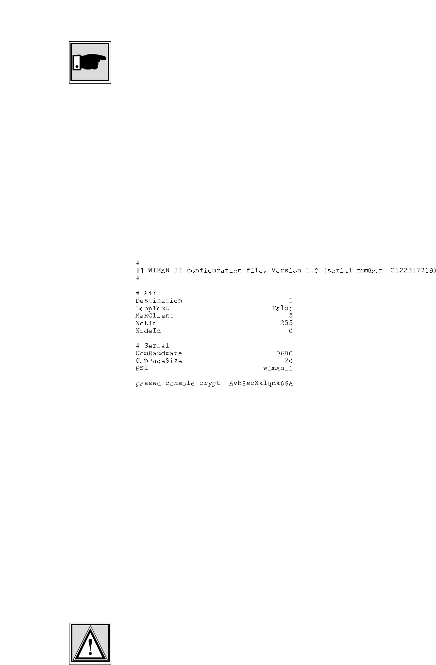
The command Export makes it possible to export the configura-
tion parameter values into an ACSII-file. The Serial number of
the WIMAN as well as the encrypted passwords are put out, too.
The range of the parameter values depends on the authorization
level in which you are when issuing this command. At the end
of the configuration file, the passwords for the individual
authorization levels are exported in encoded form, excluding the
passwords for the authorization levels you have no access to.
Figure 6 shows a possible configuration file.
Figure 6 exported configuration file
The instruction <parname> <value> enables you to occupy the
defined parameter <parname> with the defined value <value>.
This is the "classic” command for adapting the WIMAN to your
specific requirements. This instruction can be executed in con-
figuration mode only!
The instruction save transfers the present configuration into the
non-volatile configuration. This instruction can be issued only in
the command mode.
The instruction Restore enables a transferring of the parameter-
values from the non-volatile configuration into the new configu-
ration. All modifications completed before are overwritten. This
instruction can be issued in the configuration mode only.
Attention:
Since the parameter-values of the non-volatile configuration do
not have to correspond with the values of the present configura-
tion, an operational disturbance can occur. This can happen due
Save
Restore
Export
<parname>
<value>
2 The WIMAN Command Line Level
29 / 87l
to a false configuration when leaving the configuration mode
with simultaneous transfer of the data into the present configu-
ration (the query when leaving the config mode was acknowl-
edged with y).
Before storing of the data into the present configuration, be sure
that the parameters are occupied with the values necessary for
your configuration.

2 The WIMAN Command Line Level
30 / 87
2.6.3 General instructions
The instruction Help displays a summarized list of instructions.
The output on the command line level appears as follows:
WIMAN_Star # help
WIMAN II Wireless Data Communication Equipment
(c) 1999-2000 ALTVATER AIRDATA Systems GmbH & Co. KG, Bad Rappenau Germany
Built-In shell commands:
config - enter config mode
clear - clears a VT 100 screen
clear stat <type> - clears the statistic <type>
exit - exit configuration shell
export - export configuration
help - display these few helpful help lines
reset - reset unit
save - save running config to boot config
show - display running config and differences to boot config
show <regex> - display parameter(s) matching <regex>
stat <type> - display statistic information of <type>
swupdate <swlst> - get software update list <swlst> from TFTP Server
How to use command line editing, the shell history function and
the syntax of a valid <regexp>, please see the user's manual.
Figure 7 Help display output
The input of a valid parameter name alone leads to textual in-
formation available for this parameter. The admissible scope for
this parameter is displayed and the factory-installed preset value
are displayed, too.
The command CLEAR deletes the display on the command line
level of the respective terminal program (e.g. Telix or telnet
window).
The instruction reset restarts the WIMAN (Hardware reset).
<parname>
reset
Help
clear

2 The WIMAN Command Line Level
31 / 87l
2.6.4 Statistics Instructions
The WIMAN radio modem collects statistics data and system in-
formation on both software and hardware as. In case of an error,
a very exact search for the cause of the error is possible with the
help of the statistics explained below.
The command Stat displays a list of the available statistics. The
display output appears as follows:
WIMAN_Star # stat
The following statistics are available:
serial - serial interface statistics
eth - ethernet interface statistics
fr - common frame relay information
fr<dlci> - traffic on frame relay <dlci>
frmap - show dlci switching map
wl - common wireless interface information
wl<n> - traffic on wireless interface node <n>
qos<n> - actual quality of services wireless interface <n>
ipif - IP interfaces
iproute - IP routing table
tp - transparent interface statistics
sync - RF and external synchronisation
hw - hardware statistics
sw - software statistics
update - software update statistics
sysmsg - system messages
syserr - system errors
date - actual date and time
Figure 8 the statistics assistance display
The instruction Stat <type> displays the statistics specified with
<type>. The following statistics can be selected:
• serial
supplies statistics of all serial interfaces
• fr
supplies general Frame Relay information
• fr<dlci>
supplies information of a certain Frame Relay channel
(DLCI)
• wl
supplies general information of the wireless interface
• wl<node>
supplies information about the data communication to a
certain WIMAN ACCESS selected with NodeId
• qos<n>
Quality of service. Supplies performance information about
the grade of transmission
Stat <type>
Stat

2 The WIMAN Command Line Level
32 / 87
• sync
supplies information about the synchronization status of the
WIMAN.
• sysmsg
supplies a list with system messages
• syserr
supplies the system error list
• hw
supplies a list with hardware statistics
• sw
supplies a list of software statistics
• tp
supplies traffic information for the wireless hardware driver
• lbt
listen before talking
• con
supplies login-information about the wireless connection
• eth
supplies information about the ethernet connection
• date
supplies information about the time and date
• update
supplies information about the status of a TFTP-update
The parameters serial, fr, wl and qos can supply extended in-
formation by adding the switch <ext> to the instruction, e.g.
stat wl1 ext.
By adding the switch cont=<x> you can achieve continuous
output. The <x> gives the amount in seconds how fast the up-
date-interval of the output shall be. This function is especially
useful when performing a looptest, e.g. stat qos1 cont=2 dis-
plays information about the Quality of Service on the wireless
interface 1 in continuous mode. The display is updated every 2
seconds.
The instruction Clear stat <type> sets the counter statistics-
display of the device specified with <type> back to zero. The
setting of <type> to ALL clears all statistics.
Clear stat <type>

33 / 87l
3 Configuration of the WIMAN radio modem
3 Configuration of the WIMAN radio mo-
dem
To adjust the WIMAN to your specific network needs it is nec-
essary to modify some of the factory-installed preset parameters.
This modification of the WIMAN can be executed via three dif-
ferent types of interfaces:
• the wireless interface
• the RS-232-interface
• the X.21-interface.
Access to the command line level via the serial RS-232-interface
can take place with the help of a terminal program without pre-
vious configuration of the WIMAN. The access to the command
line level via the wireless interface and the X.21-interface re-
quires a previous configuration of the WIMAN.
3.1 Access to the Command Line Level over the
Wireless Interface
To access the command line level over the wireless interface
you have to use a TELNET-Program like NETTERM or the
like. Just enter the correct IP-address of the WIMAN you want
to administer and connect. You will receive the same display as
if connecting via a serial cable.
The big advantage is that you can connect to any WIMAN, no
matter where it is situated, and that you have the same function-
ality as when connecting directly via cable.
Checklist:
To access the WIMAN radio modem via the wireless-interface
you need:
• A Terminal program (Telix, Hyperterm, etc.),
• A PC/Laptop with an online connection
• A properly configured WIMAN unit
34 / 87
3 Configuration of the WIMAN radio modem
3.2 Access to the Command Line Level over the RS-
232 Interface
Checklist:
To access the WIMAN via the serial RS-232-interface you need:
• Terminal program (e.g. ZOC, TELIX),
• PC/Laptop with a free serial interface (e.g.. Com1, Com2)
• Hybrid cable (see chapter 8.3 on page 72)
• RS-232-connection cable with proper 9- or 25-pin plug/
socket, which fit to the plug/socket of the serial interface of
the PC/Laptop as well as to the RS-232-interface of the hy-
brid cable.
• Power supply for the WIMAN (supplied with the WIMAN
hardware)
Follow these steps to access the command line level of the
WIMAN:
1. Connect the hybrid cable with the 37pin D-Sub connector at
the backside of the WIMAN.
2. Connect one side of the RS-232 cable with the serial inter-
face of the PC and the other side with the RS-232 link of
the hybrid cable.
3. Connect the DIN plug of the power supply with the hybrid
cable and the plug of the power supply with an AC socket.
The illuminated power LED on the front of the WIMAN
will indicate that the WIMAN is activated.
Figure 9 shows the arrangement of equipment for the configura-
tion of the WIMAN radio modem.
RS232-cable
WIMAN-unit
Com
p
uter with VT1xx-emulation
Figure 9 arrangement of equipment for the configuration
of the WIMAN radio modem
4. Start the PC and afterwards the terminal program.

35 / 87l
3 Configuration of the WIMAN radio modem
The operating system of the WIMAN has an integrated com-
mand line interpreter ("Shell") for configuration. Input and out-
put is shown on the input/output window of the PC terminal
program (e.g. TELIX, ZOC), which must be able to emulate a
VT-terminal (DEC). The communication parameters of the ter-
minal program and the WIMAN must correspond so that the
WIMAN and the Computer can communicate.
Note:
The default settings of the RS-232-interface of the WIMAN is
adjusted to a data rate of 9600 Bit/s, a data length of 8 data bits,
one stop bit and no parity check (8N1). As handshaking proce-
dure software handshaking is configured.
To ensure that the terminal program uses the same parameters,
set the communication parameters of the terminal program to the
values stated above. If these parameters were not set correctly
communication with the WIMAN radio modem is not possible.
These values can be preset in the terminal program, thus starting
the terminal program immediately with the suitable settings.
After the WIMAN is attached to the operating voltage, it
switches itself into the transparent data-communication operat-
ing mode. Pressing the INPUT key in your terminal program
brings you to the command line level of the WIMAN.
The command line prompt should appear as follows:
WIMAN II Configuration Shell (TTY connection)
WIMAN-II >
If the WIMAN is not configured to the factory-installed de-
faults, another command line prompt may appear. It is also pos-
sible that the first authorization level of the command line level
is protected by a password.
If so, the following message appears:
WIMAN II Configuration Shell (TTY connection)
Enter password:
In this case you need the password of the supplier of the
WIMAN. If the password should not be available, please contact
your WIMAN Distributor.
Note:
If you do not arrive at the command line level of the WIMAN or
if only “confused” characters are shown on the screen after you
have adjusted the above mentioned settings, do not be con-
cerned. It may be that the configuration of the WIMAN has al-
ready been modified. In this case test different adjustments re-
garding the Baud-rate, the Stop-bits, etc.

36 / 87
3 Configuration of the WIMAN radio modem
3.3 Access to the command line prompt via the
X.21-interface
Will be created later
3.4 Setting of the Parameters of the Differnt Inter-
faces
3.4.1 Setting of the Parameters for the Wireless Interface
The settings of the parameters for the wireless interface can be
divided into the following two categories:
• base parameter and
• extended parameters.
The base parameters destination (see page 17), LoopTest (see
page 19), NetId (see to page 19) and NodeId (see page 19) can
be modified already in authorization level one (e.g. by the final
customer).
The extended parameters (all remaining parameters in section 2,
on page 38) can only be modified in authorization level two.
To set the base parameters for the wireless interface:
Checklist:
You need the values of the parameters destination (only LINE),
NetId and NodeId. To obtain these values please check with
your Provider.
1. Access the command line level of the authorization level
one (see chapter 2) and change into the configuration mode
by entering the config -command. You will receive a simi-
lar display output (depending on the prompt configured)
like:
WIMAN-II (config) >
37 / 87l
3 Configuration of the WIMAN radio modem
2. Type in the command show.
You will receive a list of the changeable parameters in
authorization level one e.g. in the following display output:
WIMAN_Star (config) > show
Config mode running config ( new config)
# Wireless
NetId 250
NodeId 0
# Serial
SerBaudrate 2048000
# Console
ConBaudrate 9600
# Network
IPSerAddress 192.168.40.2
IPSerMask 255.255.255.224
All changeable parameters for the wireless interface are
listed under the category “#Wireless”.
3. Modify the parameters according to the specifications of
your Provider. Type in the parameter, followed by a blank,
next add the value of the parameter and press ENTER.
NetID 255 ↵
NodeId 2 ↵
4. Check with checkcfg whether all values for the parameters
were input correctly. If the inputs were correct, you will re-
ceive the following display output:
WIMAN-II (config) > checkcfg
parameter check successful
In case of an incorrect input you receive an error message
with output of the accepted parameter e.g.:
wimanii (config) > checkcfg
bad value: NodeId
configuration invalid
5. Type in the instruction show again to compare the input
values with the values given by your Provider. The new
configuration of the parameter is displayed in parentheses.
Access_01 (config) > show
Config mode running config ( new config)
# Wireless
NetId 250 ( 255)
NodeId 1 ( 2)

38 / 87
3 Configuration of the WIMAN radio modem
6. In order to transfer the modifications into the current con-
figuration leave the configuration mode with exit (see
page 27).
The following display output appears::
Configuration changed, do you want to save (y)es
/ (n)o / (c)ancel ?
You now have the choice to do one of the following:
- Transfer the new configuration to the current configuration
and to leave the configuration mode by pressing the key " y,
- Leave the configuration mode without transferring the new
configuration to the current configuration by pressing the
key " n "
- Remain in the configuration mode and repeat the configu-
ration or do another modification of parameters (if neces-
sary) by pressing the key " c ".
In order to maintain the values after a restart it is necessary to
store them in the non-volatile configuration. This can be done in
two ways:
• With input of the command save (see page 28) in the com-
mand mode.
All modifications made at this configuration are stored in
the non-volatile configuration and are available after a re-
start.
The command-mode will not be left.
• With input of the command exit (see page 17) in the com-
mand mode.
When leaving the command mode the WIMAN radio mo-
dem checks whether the present configuration modifica-
tions are available for non-volatile configuration. Since you
made some modifications the following display output ap-
pears:
Boot config differs from running config, save
(y)es / (n)o / (c)ancel ?
You now have the choice to do one of the following:
- Transfer the modifications to the non volatile configuration
and to leave the command mode by pressing the key "y",
- Discard the modifications and leave the command mode by
pressing the key “n“ or
- Don’t take over the modifications but stay in command
mode and redo some modifications by pressing the key “c”
To set up the extended parameters for the wireless interface:
39 / 87l
3 Configuration of the WIMAN radio modem
Attention:
In order to avoid disturbances in the current line operation, only
qualified personnel in arrangment with the Provider may carry
out these modifications.
Checklist:
You need a list of the parameters configured by your Provider.
1. Access the command line level of the authorization level
two (see chapter 2 on page 13) and change into the configu-
ration mode with the command config.
2. Proceed as shown under point 2. during adjustment of the
base parameters and replace thereby the term " authoriza-
tion level one " with " authorization level two ".
3.4.2 Setup of the Parameter of the serial interfaces
The adjustments of the parameters for the serial interfaces can
basically be divided into the following two categories:
• Basic parameter and
• extended parameter.
The only base parameter that can already be modified in
authorization level one (e.g. of the final customer) is ConBau-
drate (see page 21).
All other parameters (see chapter 2 starting from page 13) may
exclusively be modified in authorization level two.
To set the parameters of the serial interfaces:
Proceed as shown in Chapter 3.4.1 on page 36
3.4.3 Setup of the network parameter
The setting of the network parameters can exclusively be exe-
cuted in the authorization level two. You will find the defini-
tions of the individual parameters in chapter 2 starting on
page 23.
To setup the network parameter:
Attention:
In order to avoid disturbances of the current line operation, only
qualified personnel in arrangement with the Provider may exe-
cute these adjustments.
Checklist:
You need a list of the parameters that can be configured of your
Provider.

40 / 87
3 Configuration of the WIMAN radio modem
Proceed as shown in Chapter 3.4.1 on page 36
3.4.4 Setup of the other parameters
The only other parameters are PS1 and SyncMode (see page 25).
Note:
In order to avoid disturbances of the current line operation, only
qualified personnel in arrangement with the Provider may exe-
cute these adjustments.
Proceed as shown in Chapter 3.4.1 on page 36
3.5 Modification of the WIMAN Passwords
This section deals with the configuration of the passwords of the
WIMAN radio modem. Before you alter the factory-installed
preset passwords make sure to jot down the new passwords and
store them in a safe place.
3.5.1 Setting of a Password for the Authorization Level
one (console)
To change/set a password for the authorization level one:
1. Access the command line level one. If the command line
prompt appears (for example: WIMAN II >), proceed to
No.2.
If you are asked for a password, e.g.:
Enter password: ****
Type in the correct password and press the ENTER-
key. Now the command line prompt should appear, for
example:
WIMAN-II > _
Information:
The following instructions can be issued likewise from all
higher authorization levels.
2. Change from the command mode of the authorization level
one (indicated by the character " > " at the end of the com-
mand line prompt) into configuration mode by entering the
command config.
The command prompt of the configuration-mode appears:
WIMAN-II (config) >
3. Type in the command passwd console and press ENTER.
You are now asked to type in a password:

41 / 87l
3 Configuration of the WIMAN radio modem
Enter password:
4. Type in the new password.
Note:
Keep in mind that the password is case-sensitive
If a password is already set it will be overwritten.
Each entered character is shown as a „*“ on the screen.
The new password is saved in the new configuration and is
not yet active.
5. Type in exit and leave the configuration mode (see
page 27).
6. Proceed as shown in chapter 3.4.1 on page 36.
3.5.2 To delete a Password for the Authorization Level
one
To delete a password for authorization level one:
1. Access the command line prompt of the authorization level
one.
The display will show the following:
Enter password: ****
Type in the required password. Remember that passwords
are case-sensitive.
The command-line prompt appears, for example:
WIMAN II >
Information:
The following instruction can be issued likewise from all
higher authorization levels.
2. Change from the command mode of authorization level one
(indicated by the character " > " at the end of the command
line prompt) into the configuration mode by input of the
command config.
The command prompt of the configuration-mode appears:
WIMAN-II (config) >
3. Type in the command del passwd console and press
ENTER.
The former password is now deleted in the new configura-
tion.

42 / 87
3 Configuration of the WIMAN radio modem
4. Leave the configuration mode by entering the command
exit (see page 17).
5. Proceed as shown in chapter 3.4.1 on page 36.
3.5.3 Setting of a Password for Authorization Level two
(Enable)
A password for authorization level two is always required.
However, it can be changed to suit the requirements of the Pro-
vider.
To change the password for authorization level two proceed as
follows:
1. Access the command line prompt of authorization level
two:
a) Access authorization level one (See chapter 3.5.1on
page 40)
b) Enter the command enable.
As a password is always required, you need to enter
the correct password
Enter password: ****
Type in the correct password (pay attention to upper-
and lowercase characters) and press ENTER.
c) The command line prompt appears, e.g.:
WIMAN-II #
Proceed with No. 2.
Direct entrance over the password-protected com-
mand line level of authorization levels one and two:
When accessing the command line prompt of authori-
zation level one the following prompt will appear::
Enter password: ****
Enter the password for the authorization level two (pay
attention to upper- and lowercase characters).
The command line prompt should appear, e.g.:
WIMAN-II #
2. Change from the command mode of authorization level two
(indicated by the „#“- sign at the end of the command line
prompt) into the configuration-mode by entering the com-
mand config.
The command line prompt may look as follows:
WIMAN-II (config) #
3. Enter the command passwd enable and press ENTER.

43 / 87l
3 Configuration of the WIMAN radio modem
4. You are now asked for entering a password:
Enter password:
5. Enter the password.
Note:
Please note that passwords are case-sensitive.
Each typed-in character will be shown on the screen as a
„*“. The already existing password will be overwritten.
The entered password will be stored in the new configura-
tion but is not set active yet.
6. Leave the configuration mode by entering the command
exit (see page 17).
7. Proceed as shown in chapter 3.4.1 on page 36.
3.5.4 Deletion of a password of the authorization level
two (Enable)
A password for authorization level two (Enable-mode) is always
required and cannot be deleted. However, it can only be changed
(see 3.5.3, on page 42)

44 / 87
4 Hardware Installation
4 Hardware Installation
4.1 Installation instructions for the WIMAN Access-
radio modem
The following sections deal with the installation of a WIMAN
ACCESS radio modem on a single PC containing the operating
system Windows.
Linking to a LAN requires an experienced network administra-
tor. The method of installation depends strongly on the type of
LAN
4.1.1 Setup of the WIMAN radio modem with Indoor-Set
A reception test must be successfully completed for accurate set-
up (see chapter 5, on page 55)
Checklist:
You will need the following equipment:
• PC/laptop with 10 Mbit/s Ethernet Network interface card
(TP-RJ-45-interface) and an available COM port,
• Frame Relay router with X.21 and Ethernet interfaces (in-
clusive X.21-link cable),
• Crossover cable with RJ-45-interface,
• Hybrid-cable type H1-X21C-37,
• WIMAN radio modem and indoor set.
It is advisable to execute the setup of the indoor installation in
following order:
1. Install the antenna to the base foot and connect the antenna
lead to the antenna.
2. Connect the antenna cable and the Hybrid-cable to the
WIMAN.
3. Connect the X.21-cable of the Router to the Hybrid-cable
and the crossover cable with the network card of the com-
puter.
4. Connect the power cable of the WIMAN with the included
24V power supply. Connect the power supply of the
Router.
45 / 87l
4 Hardware Installation
Note:
There is no power switch on the WIMAN. The connection
is successful when the operational status indicator on the
front side of the WIMAN lights up green.
5. Connect the RS-232-interface to the computer interface. If
you use the serial interface of a PC or Notebook, please re-
fer to the configuration specified in Chapter 3 on page 33.
As soon as it is attached to the power supply, the WIMAN
ACCESS begins to boot and starts to search for the proper
WIMAN STAR. When the synchronization signal is received,
the Status LED begins to light up green.
If the status indication does not light up, no data can be trans-
mitted or received.
If this occurs, separate the WIMAN from the power supply and
then reattach it. If the status indicator still does not light up,
please consult your Internet Provider for support.
4.1.2 Setup of the Outdoor-Set
4.1.3 Required material
Checklist:
The following material should be supplied from your Distribu-
tor:
• WIMAN radio modem,
• WIMAN power supply,
• Router (optionally),
• 25 pin loop-back cable
• Outdoor Set consisting of:
- Outdoor-box with security clips,
- Planar Antenna,
- Antenna cable, 50cm,
• X21-Hybrid-cable-set consisting of:
- Hybrid-cable, type 2,
- Hybrid-cable, type 3,
- Socket 25pin and housing (2x each),
• Data cable, 12pin, length depending on installation,

46 / 87
4 Hardware Installation
• WIMAN outdoor mounting set. The following three types
are available:
- J-shaped wall attachment set,
- Roof pan attachment set,
- Wall attachment set with aluminum mast,
Additionally the following tools and utensils are needed:
• PC-Laptop,
• Voltmeter,
• Phillips- and flat edge screwdrivers,
• Flat-nose pliers and/or wrench,
• Fixing bolts, wearing parts and pegs,
• Insulating tape and cable strap,
• Ladder,
• Soldering irons and tin solder,
• Side cutters,
• Stripping pliers (recommended),
• Tweezers (recommended),
4.1.4 Find a suitable place for the outdoor-set
Before you can begin with the installation you must find a suit-
able place for the outdoor set.
Try to choose a place on the rooftop where there is a visible line
of sight to the central radio tower. Consider the following:
• For best results, the antenna on the outdoor housing should
directly face the receiving station (line of sight).
• Trees, plants, other buildings, walls, etc. can prevent a clear
line of sight.
• Determine the shortest path for the data cable. The maxi-
mum length of the data cable may not exceed 300ft.
• For installation, choose a discreet place that is not directly
noticeable from the ground. However, aesthetic views are
secondary in respect to a proper operation of the WIMAN.
• Be sure that no other antenna systems operating in the
2,4 GHz ISM band are installed at the selected installation
point. If such an antenna system is installed there, contact
your WIMAN Distributor.

47 / 87l
4 Hardware Installation
• Be sure to discuss the details of installation with the cus-
tomer in respect to the local construction and homeowner
regulations.
4.1.5 First Reception Test
This first reception test serves to determine if the optimum field
strength can be obtained from the installation place and adjust-
ment of the WIMAN outdoor sets.
Further information about reception tests can be found in chap-
ter 5 on page 55.
4.1.6 Installation of the Attachment Set and the Outdoor
Housing
To set up the outdoor housing:
1. Assemble the outdoor housing.
2. Attach the antenna to the outdoor box with the plug facing
down.
3. Loosen the four screws on the front of the outdoor housing
and remove the cover.
4. Loosen the four fixing bolts for the WIMAN mounting
plate on the inside and remove it.
5. Place the WIMAN inside the housing with the LEDs facing
upwards and the backside (with the connector) towards the
opening of the housing.
6. Lead a cable strap through the two holes in the mounting
plate (the cable strap later serves for the attachment of the
hybrid cable of the type 3).
7. Secure the mounting plate above the WIMAN.
8. Connect the appropriate ends of the hybrid cable of the
type 3 with the 37Pin Sub-D-interface and to the current
supply link.
9. Place the excess cable in the space between the WIMAN
and the outdoor housing in such a way that the 25pin plug
connector is hanging over the front the mounting plate.
10. Connect the data cable with the hybrid cable and secure the
plug connectors with the cable strap. To ensure positive
connection at all times, install 2 hex nuts between the con-
nectors.
11. Use the screws, wearing parts and pegs to install the appro-
priate attachment set onto the roof or at the wall.

48 / 87
4 Hardware Installation
- Use the j-shaped wall mount if you are installing the
WIMAN on the side of the building directly facing the ra-
dio tower.
Use the aluminum mast mounting kit if you are installing
the WIMAN not facing the radio tower directly due to an
obstacle (e.g. rear side of a wall etc.).
Use the tile roof mounting set if you are installing the
WIMAN to a roof with roofing tiles.
4.1.7 Second Reception Test
Perform a second reception test to ensure that the selected place
of installation and the selected adjustments offer a sufficient ra-
dio reception.
Separate the current supply and the RS232-plug from the Hy-
brid-2-cable on the WIMAN radio modem.
Further information of the execution of a receipt test can be ob-
tained in chapter 5 on page 55.
After the radio test is completed, reconnect the current supply
and the RS232-plug to the Hybrid-2-cable on the WIMAN.
4.1.8 Installation of the data cable
With some installations, it is possible to use a prefabricated ca-
ble of desired length with two 25pin Sub-D plug connectors.
However, this is not possible with most installations. If no pre-
fabricated cable can to be used, it is advisable to attach a plug
connector at one end of the cable prior to installation.
Lay the data cable from the outside inward. Make sure the end
with the 25pin Sub-D connector is outside. It is substantially
simpler to solder the second plug connector on in the internal
area than in the external area.
Be sure that the data cable is sufficiently fixed to the mounting
sets, the mast and to the wall.
Wind up all surplus cables and stow them away. Wind the cable
up in one or two turns. This measure serves as additional light-
ning protection for the router.
4.1.9 Mounting of the DB25-plug interfaces at the inside
end of the data cable
Solder the two 25pin plug connectors to the data cable according
to the pin allocation plans specified in chapter 10.

49 / 87l
4 Hardware Installation
4.1.10 Final reception test with installed data cable
The final reception test is necessary for two reasons: First to ex-
amine the assembly position of the WIMAN, second, and more
importantly, to test the data link between the Router and the
WIMAN.
You will find details to the reception tests in chapter 6 on
page 58.
To perform the test, connect your Laptop to the RS232-interface
at the Hybrid-cable type 2.
If there is no connection to the WIMAN or if the connection is
unusually slow, follow the instructions specified below to locate
the source of error.
1. Make sure that the terminal program is adjusted to the cor-
rect Baud rate (9600 Bit/s).
2. The power-LED lights up in green when sufficient operat-
ing voltage is supplied, and in orange if the WIMAN per-
forms a looptest. If an internal error occurred the power
LED lights up in red.
3. Make sure that the RS-232 cable and the power-supply are
correctly connected at both ends of the data cable.
4. Double-check the solder joints and the pin-allocation inside
the plugs of the data cable.
5. Check the hybrid cables by alternating them one at a time.
4.1.11 Check the statistics of the X.21-interface
To check the statistics of the X.21-interface you must first test
the connections between the WIMAN and the Router.
To test the connections you must:
1. Ensure that Router is attached correctly and switched on.
2. Enter the instruction "stat serial ext".
This instruction displays information to the data transmitted
via the Serial-interface. The last line of the display-output
should look as follows.
Line State: Control (C): ON Indication (I): ON
If “OFF” appears in either of the signals, a connection error has
occurred. Follow the instructions given below to locate the
source of the error:
1. Check the X.21-connections at both ends of the data cable
for correct fit.
50 / 87
4 Hardware Installation
2. Double-check the solder joints and the pin-allocation inside
the plugs of the data cable.
3. Check the hybrid cables by alternating them one at a time.
4.2 Installation of a WIMAN Star
4.2.1 Additional necessary components
Checklist:
In addition to the parts specified in Chapter 4.1.2, page 45, the
following components are needed for the installation of a
WIMAN STAR:
• Tower standoffs
• 1 WIMAN Access with Indoor-Set for testing purposes
• 1 Router for testing
• Configuration files for all radio modems
4.2.2 Preparation
To install a WIMAN star:
1. Label all WIMAN units according to the convention:
XX-YYY-ZZZ.
• XX = LM (Line Master), LS (Line Slave), SM (Star Multi-
point), AS (Access)
• YYY= NetId (0-255)
• ZZZ = adjustment of the antenna (0 -359°) – towards north.
2. Install the WIMAN radio modem and Typ-3-Hybrid cable
in the outdoor housings.
3. Label the remaining WIMAN utensils according to the
convention indicated above. You should label:
51 / 87l
4 Hardware Installation
- All data cables (upper and lower end)
- All small external housings (if used)
- All antennas on large external housings (if used)
- the radio modem designated as synchronization mas-
ters, with the additional designation "Sync master",
4.3 Installation at the Radio Tower
4.3.1 Installing the tower standoff at the radio mast
4.3.2 Installing the WIMAN hardware at the tower standoff
Attach the WIMAN hardware (external housing and antennas)
to the tower standoff at the suitable positions and align. If a
WIMAN is to take over the function of the synchronization-
master and is not clocked from a remote location, always use the
unit aligned to the north (0º) as the synchronization master.
4.3.3 Installation
Install all data cables. Connect the data cables with the Hybrid
cables coming from the WIMAN radio modems.
Attention:
For correct function and error-free installation, be sure that the
sync cable is installed before testing.
4.3.4 Start tests
Now test all installed components on correct function and in-
stallation. You find a specification of the tests in chapter 6 on
page 58.
4.3.5 Checking the antenna adjustment
• Check to see that all antennas are facing the correct direc-
tion.
• Note the adjustments of all antennas.
4.3.6 Test all devices
• Make sure all devices on the radio tower are switched on
and are connected to the synchronization cable.
• Test each WIMAN radio modem again (see chapter 6,
page 58.) to make sure that there is no error caused by the
synchronization cable.

52 / 87
4 Hardware Installation
4.3.7 Save all configuration data of the WIMAN radio mo-
dems at the radio tower
• Use the same name conventions used for the cables and
WIMAN radio modems.
• Record the following information with a terminal program:
- Parameter („show“-command)
- Statistics („stat“-command)
4.4 Grounding
It is extremely important to ground all installed devices on the
radio tower. This will reduce the amount of damage should
lightning strike. The following steps will also help to reduce
possible damage caused by lightning:
• Do not mount the WIMAN at the highest point of the radio
tower. This is the point most likely to be struck by light-
ning.
• Check that the outdoor housing and the tower standoffs
form a well-grounded metal-on-metal connection with the
tower frame.
• Avoid using rubber washers or seals.
• Install lightning protection devices between the data cable
and the hybrid-sets on both the top and bottom of the tower.
• Ground the data cable to the tower at (a minimum of) three
different places. (1) to the center of the tower, (2) to the
base of the tower where the cable bends (before the bridge
from the tower to the shed) and (3) before the cable runs
into the equipment shed. The best way to do this is to strip
away the outer casing of the cable and affix a grounding
clamp to the cable shielding, then connect this clamp to a
second one which is fixed to the tower.
• Make sure that all equipment (Switches, Routers, etc.) at the
base of the tower is properly grounded to the rack in which
it is mounted. Also make sure that the rack itself is properly
grounded.

4 Hardware Installation
53 / 87l
4.5 Burst-Synchronisation
Burst-synchronization is the coordination process of frequency
hopping tables, receipt, and points of transmitting time for sev-
eral WIMAN networks within the same geographical area.
Burst-synchronization is achieved by both hardware and soft-
ware items. The hardware item is a synchronization cable, which
is only a wire, which connects the X.21-interfaces among them-
selves.
For the X.21 Interface, the synchronization cable is enclosed in
the hybrid cable type 3. This is connected to further radio mo-
dems with additional cables and special T-connectors.
The software section for synchronization consists of the pa-
rameter SyncMode, which is to be entered in the basic configu-
ration of a master or a Slave.
One master radio modem (STAR or LINE) is determined as
synchronization master for all radio modems at that location.
The synchronization master is adjusted as follows:
• SyncMode = Master
All further master radio modems should be adjusted as follows:
• SyncMode = Slave
4.6 Extended Point-to-Point Connections
An estendet Point-to-Point connection can be structured by ar-
ranging two WIMAN LINE “back-to-back”. For this applica-
tion, additional hardware is necessary. Please contact your
WIMAN supplier.
For an extended point-to-point connection the parameter
SyncMode has to be set to the base WIMAN LINE configura-
tion.
The example configurations specified below refer to an ex-
tended X.21 Point-to-Point-connection. In this structure, the
WIMAN LINE Slave 1 is coupled to the WIMAN LINE Master
2.

4 Hardware Installation
54 / 87
Line Master 1 Line Slave 1
NetId = 1 NetId = 1
NodeId = 0 NodeId = 1
Destination = 1 Destination = 0
SyncMode = (according to local Network) SyncMode = Master
Table 1 parameters of an extended point-to-point
connection (connection 1)
Line Master 2 Line Slave 2
NetId = 2 NetId = 2
NodeId = 0 NodeId = 1
Destination = 1 Destination = 0
SyncMode = Slave SyncMode = (according to local Network)
Table 2 parameter of an extended point-to-point
connection (connection 2)

5 Reception quality and transmission speeds
55 / 87l
5 Reception quality and transmission speeds
For the examination of the receipt quality as well as to error de-
tection, test loops can be generated. The type of test loop can be
influenced by the configuration of the parameters LoopData,
LoopMode and LoopTest.
The parameter LoopData enables the setting of the Byte-values
that are to be generated (see page 18). This parameter can be
produced on a WIMAN ACCESS only.
The parameter LoopTest enables a switching to a test loop, with
which the data, which can be transmitted, is produced independ-
ently by the WIMAN radio modem (see page 19).
This test loop can already be activated in the lowest authoriza-
tion level and is, in combination with the statistics analysis on
the wireless interface, an outstanding inspection procedure for
radio communication.
The parameter LoopMode determines, which bit pattern will be
transferred with the back loop in the loop test operation from the
WIMAN radio modem (see page 18)
Attention:
If the back loop test is execute in an operating radio net, avoid
all values except normal. Use of any other value may result in
loss of performance.
5.1 Configuration of a TestLoop with Independently
Generated Data Communication
1. Access the command line level of authorization level one
(see chapter 2 on page 13) and change into the configura-
tion mode. You will see an output similar to:
WIMAN-II (config) >
2. Type in the command looptest true.
3. Check with show looptest the value for the parameter
Looptest. This should now be switched to true. The fol-
lowing output appears:
WIMAN-II (config) > show looptest
LoopTest false ( true)
The present and the new configuration (in parentheses) of
the parameter are displayed.

5 Reception quality and transmission speeds
56 / 87
4. To take over the modifications into the current configura-
tion leave the configuration mode by entering the command
exit (see page 27).
The following output appears:
Configuration changed, do you want to save (y)es
/ (n)o / (c)ancel ?
You now have the choice:
- To transfer the new configuration into the current con-
figuration and to leave the configuration mode by
pressing the key „y“,
- To discard the modification but to leave the configura-
tion mode anyway by pressing the key „n“ or
- To not take over the modification into the current con-
figuration but to stay in configuration mode by press-
ing the key „c“.
Press the „y“ key to activate the looptest. The modification
of the parameter becomes part of the current configuration
and the WIMAN starts transmitting bit samples.
5.2 Test after a Radio Tower Installation with Syn-
chronisation
After all devices are correctly installed, a final test must be exe-
cuted. This final test checks if all devices are installed correctly
and whether a trouble free transmitting and receiving mode is
possible.
• Switch on the first WIMAN radio modem. Always begin
with the WIMAN determined as synchronization master.
• Radio test
- If the synchronization Master is a WIMAN STAR or a
WIMAN LINE Master, conduct a loop back test from
a properly configured WIMAN ACCESS or LINE
Slave.
- It the synchronization Master is a LINE Slave, conduct
a loop back test from its LINE Master.
• Check the X.21-interface by connecting the X.21-plug of
the Hybrid cable type-2 to the Router.

5 Reception quality and transmission speeds
57 / 87l
- For the WIMAN STAR enter the commands „stat wl“
and „stat wl<nodeID>“ to ensure proper functioning of
the data exchange.
- For the WIMAN LINE enter the command „stat sync“
to check the setting of both signals (both signals have
to be set to „On“).
5.2.1 Continue the Tests
• Switch on the WIMAN radio modem next to the synchroni-
zation master.
• Switch off the synchronization master.
• Perform a reception test.
• Check the X.21-interface (see chapter X.21-Test above).
• Switch the synchronization master back on.
• Perform another reception test to make sure the synchroni-
zation cable does not produce any errors (the radio statistics
should not differ substantially from the preceding ones).
5.2.2 Test the Remaining Modules
• Switch on the next WIMAN.
• Switch off all WIMAN radio modems that were tested be-
fore.
• Perform a reception test.
• Check the X.21-interface (see chapter X.21-Test above).
• Switch on all WIMAN units that were tested before.
• Connect the synchronization cable to the last tested
WIMAN radio modem.
• Perform another reception test to make sure the synchroni-
zation cable does not produce any errors (the radio statistics
should not differ substantially from the preceding ones).
5.3 Transmission Speeds
5.3.1 FTP-Download from an FTP-Server
The maximum transmission speed of the WIMAN radio modem
at optimum conditions is about 25 … 30 Kbytes/s at 2FSK and
about 55 … 62 Kbytes/s at 4FSK (depending on the extend of
utilization of the network).
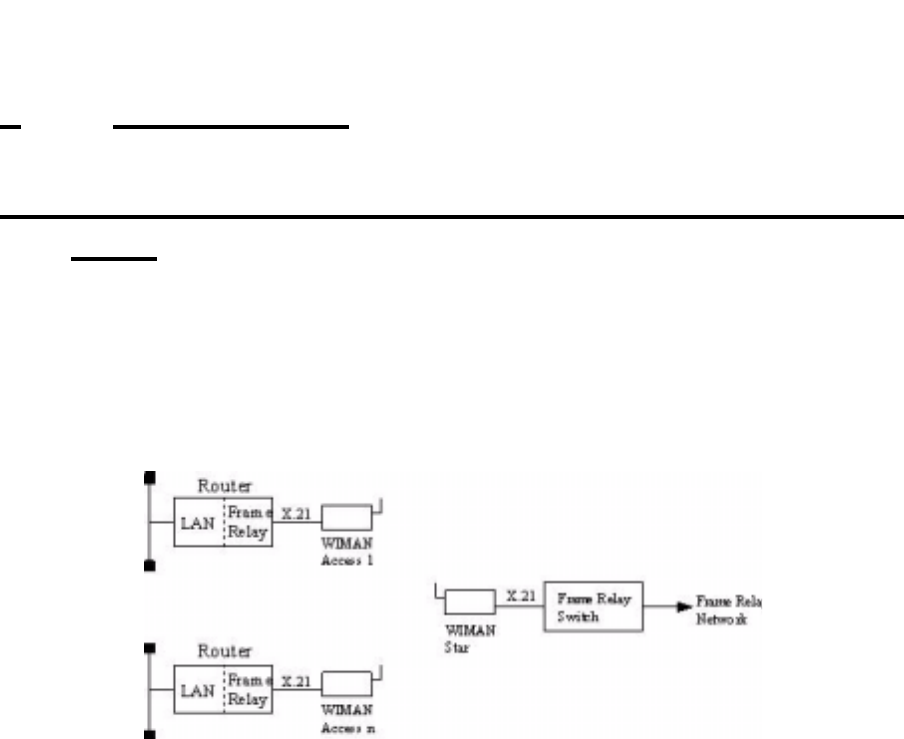
58 / 87
6 Frame Relay
6 Frame Relay
6.1 Technical Description of the Frame of Relay Fea-
tures
The WIMAN STAR supports the multiplexing of Frame Relay
packages. In multiplexing procedure, the packages received
from the Frame Relay Switches are transferred to the WIMAN
ACCESS, which is connected to a Frame Relay Router at the
user’s site.
Figure 10 Frame Relay connections with the WIMAN
For addressing the WIMAN ACCESS the DLCI number (Data
Link Connection Identifier) of the Frame of Relay protocol is
used.
The following restrictions apply to the Frame Relay support:
• Only static connections are supported (PVC = Permanent
Virtual Connection)
• DLCI numbers must be configured statically on the Frame
Relay Switch and the Frame Relay Router
• 2-, 3- or 4- Byte-Frame Relay-address-arrays are supported,
• Since the WIMAN node address is embedded in the DLCI
number (10-bit DLCI with implemented WIMAN node
identifier), the DLCI allocation of numbers is reduced
• Up to four virtual connections are supported for each Frame
Relay user
• Up to 250 Frame Relay users are supported at a WIMAN
STAR (currently 9 users possible, Software Version T0.7).
• The following Frame of Relay features are not supported:

59 / 87l
6 Frame Relay
- LMI (Local Management Interface of ITU-T Q.933 or
ANSI T1.617), since this procedure uses DLCI 1023 or
DLCI 0,
- Establishing of connections for SVCs (uses DLCI 0),
- Multiple transmissions (uses DLCI 1019 ... 1022).
6.1.1 Frame Relay-Address array
Table 3 shows the structure of the 2 Byte long Address array:
87654321
DLCI 10 DLCI 9 DLC I 8 DLCI 7 DLCI 6 DLCI 5 C/R EA
DLCI 4 DLCI 3 DLCI 2 DLCI 1 FECN BECN DE EA
Table 3 Structure of the 2 Byte long address array
Explanation:
• DLCI
Data Link Connection Identifier
• C/R
Command Response Bit
• EA
Address Array Extension Bit
• FECN
Forward Explicit Congestion Notification
• BECN
Backward Explicit Congestion Notification
• DE
Discard Eligibility Indicator
The node address of the WIMAN is determined by the high or-
der-bits (DLCI 03...DLCI 10) of the DLCI number. The low or-
der bits (DLCI 1...DLCI 2) are used for virtual connections.
2-Byte-Adress
array

60 / 87
6 Frame Relay
The LCI value for the Frame Relay Router of the user is calcu-
lated as follows:
DLCIm = 512 + NodeId * 4 + m m = [0 ... 3]
Table 4 lists the valid DLCI numbers for appropriate node iden-
tifiers (NodeId) on use of the 2-Byte-Frame of Relay address ar-
ray.
WIMAN NodeId DLCI array Note
0 512 – 515 reserved (WIMAN STAR)
1 516 – 519
2 520 – 523
3 524 – 527
4 528 – 531
5 532 – 535
6 536 – 539
7 540 – 543
8 544 – 547
9 548 – 551
10 552 – 555
11 556 – 559
12 560 – 563
13 564 – 567
14 568 – 571
15 572 – 575
Table 4 NodeId with 2-Byte-Frame Relay address array
In the following, the implementation of the Frame of Relay
Protocol within the WIMAN software is listed briefly. Exclu-
sively the static software-Version of the WIMAN STAR sup-
ports the Frame Relay Protocol with the following characteris-
tics:
• The maximum size of the Frame Relay information field
amounts to 4096 byte.
• The WIMAN star rejects Frame Relay framework with in-
valid DLCI number (transmitter and receiver).
DLCI value
calculation
Frame Relay-
support of the
WIMAN Software

61 / 87l
6 Frame Relay
6.1.2 DLCI-areas when the 2-Byte-Address array is used
(ITU Q.922)
Table 5 lists the allocation of the DLCI numbers on use of the 2-
Byte-address array.
DLCI-area Meaning
0 Signalizing in the transmission channel, if necessary
1 – 15 Reserved
16 – 511 Network option: on not-D channels, usable for the support of user
information
512 - 991 logical connecting identifier for the support of user information (the
use of semi permanent connections can reduce the DLCI numbers
available within this area)
992 - 1007 Layer 2-Management of Frame-transport services
1008 reserved
1023 Layer 2-Management in the transmission channel if necessary (only
usable without d-channel)
Table 5 DLCI allocation in connection with 2-Byte-
address array
DLCI Range10987654321
0 0000000000
1 - 0000000001
15 0000001111
16 - 0000100000
511 0111111111
512 - 1 0 0 0 0 0 0 0 0 0
911 1111011111
992 - 1 1 1 1 1 0 0 0 0 0
1007 1 1 1 1 1 0 1 1 1 1
1008 - 1 1 1 1 1 1 0 0 0 0
1022 1 1 1 1 1 1 1 1 1 0
1023 1 1 1 1 1 1 1 1 1 1
Table 6 bit sequence for different DLCI identifiers
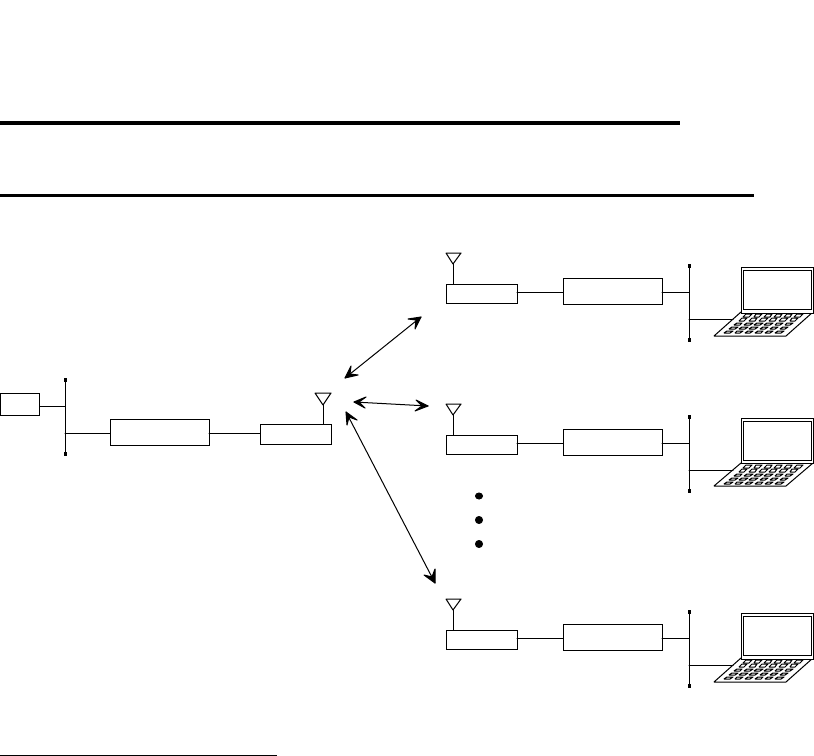
62 / 87
6 Frame Relay
6.2 Frame Relay-configuration samples
6.2.1 Sample configuration with CISCO-Routers
Star
Access 1
Cisco 1005
Cisco 1005 Service-
Notebook
GW
192.168.33.0 /24
.3
.20 .1 .2 (515)
.3 (519)
192.168.40.128 /29
.129
.130
.34
(515)
.33
(515)
Access 2 Service-
Notebook
.4 (523)
192.168.40.136 /29
.137
.138
.38
(515)
.37
(515)
Access 9 Tiny Router Service-
Notebook
.11 (519)
192.168.40.240 /29
.195
.194
.66
(515)
.65
(515)
Cisco 1005
D 516
D 520
Figure 11 Simple WIMAN Network with CISCO-Router
CISCO1, connected to STAR unit:
! Configuration Cisco Star
!
no service password-encryption
no service udp-small-servers
no service tcp-small-servers
!
hostname Cisco_Master
!
enable password wiman
!
ip subnet-zero
!
interface Ethernet0
ip address 192.168.33.20 255.255.255.0
!
interface Serial0
no ip address
encapsulation frame-relay IETF
no keepalive
no fair-queue
!
interface Serial0.1 multipoint
ip address 192.168.40.1 255.255.255.224
no arp frame-relay
frame-relay map ip 192.168.40.2 515
frame-relay map ip 192.168.40.3 519
frame-relay map ip 192.168.40.4 523
frame-relay map ip 192.168.40.5 527

63 / 87l
6 Frame Relay
frame-relay map ip 192.168.40.6 531
frame-relay map ip 192.168.40.7 535
frame-relay map ip 192.168.40.8 539
frame-relay map ip 192.168.40.9 543
frame-relay map ip 192.168.40.10 547
frame-relay map ip 192.168.40.11 551
!
interface Serial0.2 point-to-point
ip unnumbered Ethernet0
no arp frame-relay
no cdp enable
frame-relay interface-dlci 516
!
interface Serial0.3 point-to-point
ip unnumbered Ethernet0
no arp frame-relay
no cdp enable
frame-relay interface-dlci 520
!
interface Serial0.10 point-to-point
ip unnumbered Ethernet0
no arp frame-relay
no cdp enable
frame-relay interface-dlci 548
!
ip classless
ip route 0.0.0.0 0.0.0.0 192.168.33.3
ip route 192.168.40.32 255.255.255.252 Serial0.2
ip route 192.168.40.128 255.255.255.248 Serial0.2
ip route 192.168.40.36 255.255.255.252 Serial0.3
ip route 192.168.40.136 255.255.255.248 Serial0.3
ip route 192.168.40.64 255.255.255.252 Serial0.10
ip route 192.168.40.192 255.255.255.248 Serial0.10
!
line con 0
exec-timeout 0 0
line vty 0 4
exec-timeout 0 0
password wiman
login
!
end
CISCO2, connected to ACCESS01:
! Configuration Cisco Access 01
!
no service password-encryption
no service udp-small-servers
no service tcp-small-servers
!
hostname Cisco_Access_01
!
enable secret 5 $1$9xE0$1jVP/hVttHmwhWi/b1Dzv0
!
ip subnet-zero
!
interface Ethernet0

64 / 87
6 Frame Relay
ip address 192.168.40.129 255.255.255.248
!
interface Serial0
no ip address
encapsulation frame-relay IETF
no keepalive
!
interface Serial0.1 point-to-point
ip address 192.168.40.33 255.255.255.252
no arp frame-relay
no cdp enable
frame-relay interface-dlci 515
!
interface Serial0.2 point-to-point
ip unnumbered Ethernet0
no arp frame-relay
no cdp enable
frame-relay interface-dlci 516
!
ip classless
ip route 0.0.0.0 0.0.0.0 Serial0.2
no cdp run
!
line con 0
exec-timeout 0 0
line vty 0 4
exec-timeout 0 0
password wiman
login
!
end
Configuration STAR:
## WIMAN II configuration file
#
# Air
Antenna 8mn360
MaxNodeId 1
MaxRetry 9
NetId 250
RadioPower Normal
# Serial
ConBaudrate 9600
ConDataBit 8
ConHandShake Soft
ConPageSize 24
ConParity None
ConStopBit 1
PS1 WIMAN_Star
SerBaudrate 2048000
SerCRC 16
SerEncode NRZ
# Network
IPDefaultGW 192.168.40.1
IPEthAddress 0.0.0.0
IPEthMask 255.255.255.0

65 / 87l
6 Frame Relay
IPSerAddress 192.168.40.2
IPSerMask 255.255.255.224
IPTFTPServer 192.168.33.178
Location Area_01
# Sync
SyncMode Off
passwd enable crypt Av/WbhGC.i1HA3E
Configuration ACCESS01:
## WIMAN II configuration file
#
# Air
Antenna 8mn360
LoopData FF
LoopMode Long
LoopTest False
MaxRetry 9
NetId 250
NodeId 1
RadioPower Normal
# Serial
ConBaudrate 9600
ConDataBit 8
ConHandShake Soft
ConPageSize 24
ConParity None
ConStopBit 1
SerBaudrate 2048000
SerCRC 16
SerEncode NRZ
# Network
IPDefaultGW 192.168.40.1
IPEthAddress 0.0.0.0
IPEthMask 255.255.255.0
IPSerAddress 192.168.40.34
IPSerMask 255.255.255.252
IPTFTPServer 192.168.33.178
IPWLAddress 192.168.40.3
IPWLMask 255.255.255.224
Location Area_1
# Sync
SyncMode Master
passwd enable crypt Av/WbhGC.i1HA3E

7 Troubleshooting
66 / 87
7 Troubleshooting
7.1 Techniques and Methodologies Used for Trou-
bleshooting
7.1.1 General Problems
This section lists some common problems that may occur and
cause a malfunction in the WIMAN system:
Bad RF-Link between STAR (Master) and ACCESS (Slave):
• STAR units are not synchronized ! see stat sync
• Bad hardware on the STAR or the ACCESS
- Check RF statistics from the STAR to other ACCESS de-
vices ! see stat wl ext
If all other connections are functioning properly,
STAR is not defective.
• If the star is working correctly consider the following ques-
tions:
- Is the ACCESS device configured correctly (correct STAR,
correct sector)?
- Are there any obstacles between the STAR and the
ACCESS?
- Is the antenna cable attached correctly?
- Is the antenna adjustment correctly?
- Is the ACCESS device itself defective (defective transmit-
ting or receiving part)? ! If so, exchange the device.
- Are two ACCESS devices within a network configured with
the same NodeID? Check the ACCESS configuration, the
network configuration and the documentation of the other
ACCESS radio modems within in the same network.
No data communication from the STAR to the ACCESS:
• Check the radio connection between the ACCESS and the
STAR.
• Check the wiring of the STAR and ACCESS
- Check the other radio modems attached to this STAR
If data can be transmitted to the other ACCESS de-
vices then the wiring at the STAR is OK.
7 Troubleshooting
67 / 87l
If you are still uncertain whether there is a problem
with the wiring of the STAR, proceed as follows:
Check the statistics with the commands stat serial ext
and stat wl<NodeID>. If you transmit a Ping, the
Rx and Tx-counter should be increased.
Check whether the data cable is wired according to the
specifications shown in chapter 10, page 82.
Check all modules for correct wiring.
Check the hybrid cables.
Check the interface converters.
Check the cross over cables.
- Check the wiring on the ACCESS:
Check the statistics with the commands stat serial ext
(see page 49) at the ACCESS-side. If you transmit
a Ping, the Rx and Tx-counters should increase.
Check whether the data cable is wired according to the
specifications shown in chapter 10 on page 82.
Check the wiring of all modules.
Check the hybrid cables.
Check the routing tables.
• With the instruction stat hw compare the serial number en-
tered in the device table (peer-table) with the actual serial
number of the device. If the serial number does not match,
all data packages will be discarded. Enter the following to
delete an existing entry in the device table:
PEER <NodeID> <ENTER>
Afterwards reset the device.
• Check whether the looptest at the ACCESS radio modem is
still active (show looptest). The Parameter „LoopTest“ must
be set to „false“.
• Defective Router at the customer side:
- Check the configuration
- Check the Hardware
• PVC
- PVC was built on the wrong port
- PVC was built with wrong DLCI (according to the appro-
priate NodeID of the ACCESS)
• Routing tables

7 Troubleshooting
68 / 87
• Bad port on the switch
- Check other customers who are attached to the same STAR
- In case no further customers are attached to the same
STAR, try attaching the device to another port.
WIMAN Baud rate parameters are not adjusted correctly:
If the WIMAN radio modem does not interface with the termi-
nal program, the Baud rate may be set incorrectly on the
WIMAN and/or the terminal program.
Frequency table adjusted incorrectly
If the WIMAN Slave cannot construct synchronized connections
and you are using generated frequency tables, check that the pa-
rameter "FtabMode" is adjusted to "user". Make sure that all
parameters are configured correctly.
Parameter destination not adjusted correctly (LINE only)
This situation cannot occur after a loop test. If the Socket pro-
gram cannot structure a connection, check the network and en-
sure that all parameters "destination" are set to the correct value.
Baud rate in the Socket program not set correctly
If the Socket program cannot construct a connection, it could be
that the Baud rate is set incorrectly on the Socket program
and/or the WIMAN.
Parameter NodeID not set correctly
If an ACCESS radio modem receives synchronization impulses,
but no data can be transmitted, it could be that the parameter
NodeID is adjusted incorrectly. The double assignment of a
node number in the same network leads to malfunctioning.
Serial number does not correspond with the device table
(Peertable)
If the WIMAN STAR is adjusted to a serial number that differs
from the one used in the Peertable, malfunction may occur.
IP-Parameter in the Socket-program not set properly
If the Socket program over the ACCESS radio modem cannot
construct a connection, check whether all IP parameters are ad-
justed correctly.
Damaged or defective antenna cable
Damaged or defective synchronization cable

7 Troubleshooting
69 / 87l
Any of these problems may lead to poor or no radio communi-
cation. Check the antenna cables for damages. If there are no
damages, check the synchronization connection. If the problem
persists, the WIMAN may need to be replaced.
7.1.2 Troubleshooting with Radio Tower Installations
• If the WIMAN radio modem can not be accessed over the
RS-232-interface, the problem may be caused by:
- A non-corresponding Baud rate of the terminal program and
the WIMAN (usually the Baud rate is adjusted to 9600
Baud)
- Incorrectly attached cables
- Faulty Hybrid-2 or Hybrid-3-cables. Exchange the Hybrid-
2-cable first and then the Hybrid-3-cable (if necessary).
- Faulty contacts inside the data cable plug. Check the con-
figuration and transmission with an extra 25pin data ca-
ble.
• In case the ACCESS can get no RF-synchronization signal
(indicated by the Status-LED at the front side of the unit) or
if the synchronization signal reception is periodically inter-
rupted, the problem may be caused by:
- Incorrect configuration of the ACCESS or STAR. Check
whether all parameters are correct.
- The operating voltage at the star radio modem is too low. If
the operating voltage at the WIMAN radio modem drops
below the given threshold value, a restart is performed
automatically. It is advisable to constantly apply a volt-
age at the radio modem by at least 12V.
- Defective or unattached antenna cable,
- A Faulty Hybrid-2 or Hybrid-3-cable. Replace the Hybrid-
2-cable first and then the Hybrid-3-cable (if necessary).
- Defective RF filters.
- Defective WIMAN STAR or ACCESS.
- Faulty contacts inside the data cable plug. Check for perfect
configuration and transmission with an additional 25pin
data cable.
- Defective synchronization cable (short-circuit in the plug)
of and to the testing device.
- Defective T-connector (short-circuit)
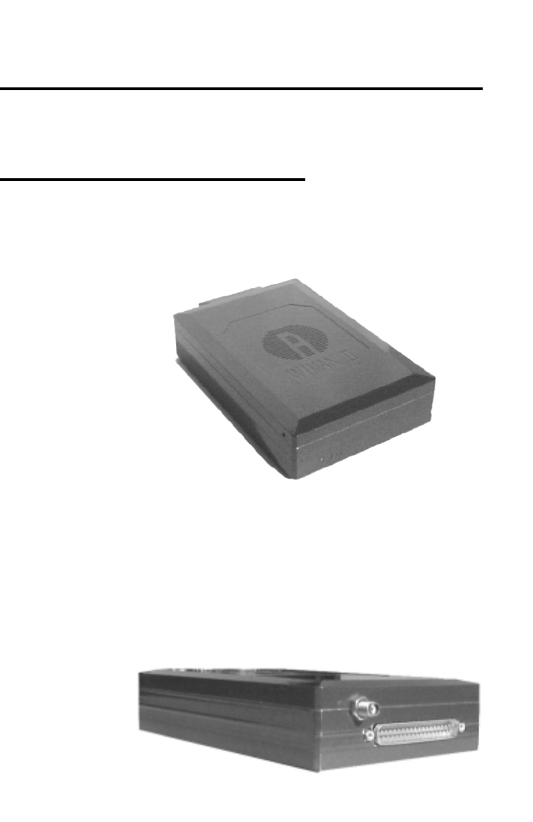
70 / 87
Appendix A: WIMAN Hardware
8 Appendix A: WIMAN Hardware
!!!!!!!!!!Still being revised!!!!!!!!!!!!.
8.1 Technical description
Below you will find pictures of the WIMAN units:
Figure 12 front side of the WIMAN radio modem
Figure 13 rear side of the WIMAN radio modem

71 / 87l
Appendix A: WIMAN Hardware
8.2 Antenna systems
Different antenna systems are available for the WIMAN radio
modem:
• Omni-directional antennas with a gain of 2 dBi.
These antennas are used typically for the installation of the
WIMAN star or WIMAN Bridge stations.
Dimensions: Length 120cm/4ft, diameter 5cm/2in
• Planar array antennas with an opening angle of 75° azi-
muth, 60° elevation and an antenna gain of 8,5 dBi.
Another antenna type provides an opening angle of 27°
azimuth and elevation and an antenna gain of 16dBi.
These antennas were developed mainly for the application
on the customer side in connection with the WIMAN
ACCESS. In addition, they are suitable for point-to-point
connections in connection with the WIMAN LINE.
Dimensions:
10cm x 10cm x 3cm /4in x 4in x 1.2in (8.5 dBi)
• Paraflector antennas with an opening angle of 7,5° azi-
muth and an antenna gain of 23 dBi.
These antennas were developed particularly for point-to-
point connections over a large distance
Dimensions: 100cm x 60cm x 60cm/40in x 24in x 24in.
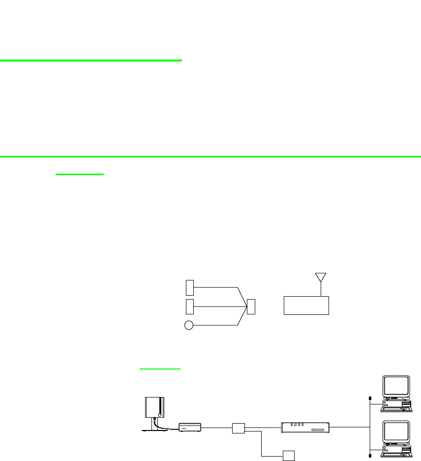
72 / 87
Appendix A: WIMAN Hardware
8.3 Hybrid-cable sets
Nachfolgend sind einige Anschlussbeispiele für die
verschiedenen Hybridkabel aufgeführt. Eine genaue
Beschreibung der einzelnen Hybridkabel ist in Kapitel 8.4 auf
Seite 75 nachzulesen.
8.3.1 Standard Connection (Indoor) using Hybrid cable
Type 1
Hybrid-cable Type 1 is only used when a WIMAN is directly
connected to a Router (e.g. CISCO). This type of connection can
be used for devices, which are in close range to the Router (In-
door-Installation).
SubD 37 F
SubD 15 F
SubD 9 F
DIN M
(H1-X21C-37)
X.21
Config
24 V
WIMAN
Sample:
Frame Relay
Access Device
Power supply
Hybrid-
cable
WIMAN Access
(incl. Planar-
antenna) LAN
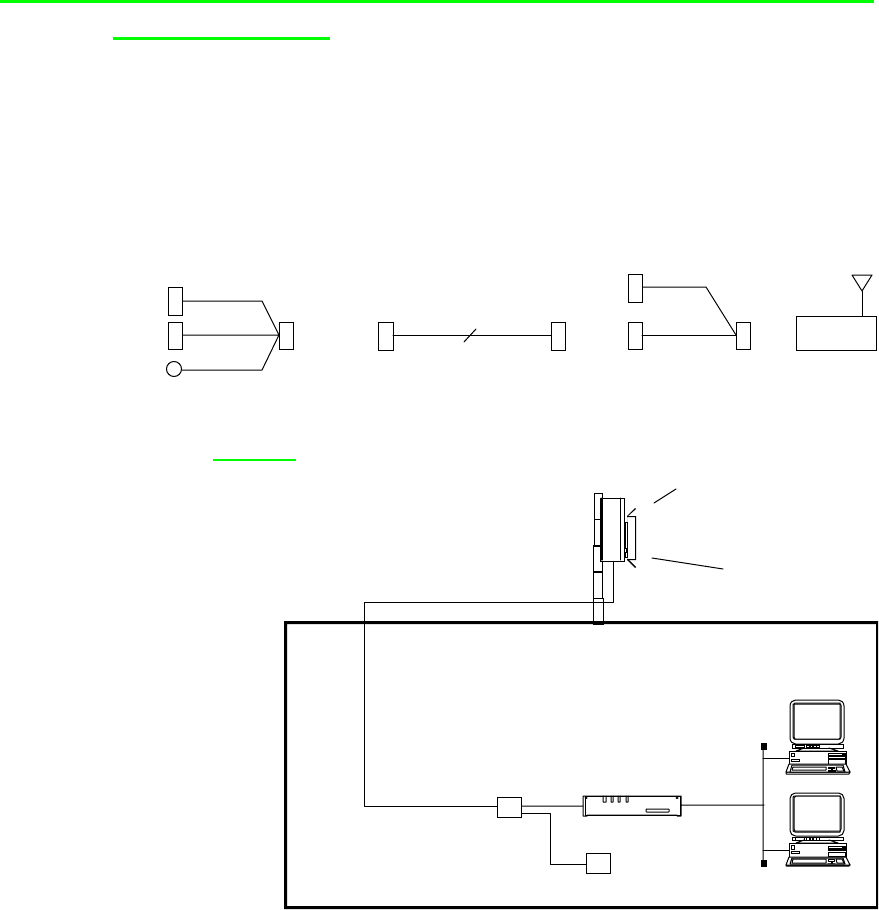
73 / 87l
Appendix A: WIMAN Hardware
8.3.2 Outdoor Installation using Hybrid cable Type 2 & 3
and Datacable
This connection is used when the WIMAN is installed on a
rooftop or a radio tower and is synchronized among other
WIMAN devices. In addition a data cable (12x2) is needed.
SubD 25 M SubD 37 F
SMA F
SubD 25 F
(H2-X21C-25)
12 x 2
(H3-X21C-37)
SubD 15 F
SubD 9 F
DIN M
X.21
Config
24 V SubD 25 F SubD 25 M
Syncronization
Datacable
(max. 100m) WIMAN
Sample:
WIMAN Access
Outdoor-Set
(incl. Planar-Antenna
and Hybrid-Cable)
Frame Relay
Access Device
Power Supply
Hybrid-
Cable
LAN
Datacable
(max. 100m )
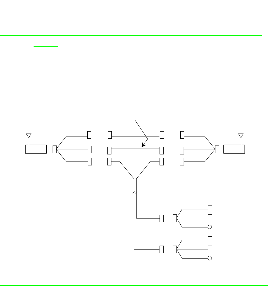
74 / 87
Appendix A: WIMAN Hardware
8.3.3 Connection of a remote POP with WIMAN LINE and
STAR
This link is used for a remote Point Of Presence, if a WIMAN
STAR is connected via a WIMAN LINE link. Here the STAR
receives the synchronisation impulses likewise via the LINE
link.
SubD 37 F
SMA F
V.24 +
24 V
Syncronization
RG 316
X.21 Zeromodem
S 25 F
V.24 + 24 V
12 x 2
SMA M
SubD 25 F
SMA M
SubD 15 F
SMA F
SubD 15 M
SubD 25 M
V.24 +
24 V
X.21
Syncronization
Hybrid Cable Type 4
(H4-X21C-37)
Zeromodem X.21
(NULL-X21C-15)
SubD 15 F
(not connectible)
SubD 9 F
DIN M
Hybrid Cable Type 2
(H2-X21C-25)
S 25 F
S 25 M
S 25 M
Config
24 V
SubD 9 F
DIN M
Config
24 V
(H4-X21C-37)
SubD 15 F
(not connectible)
SubD 25 M
WIMANWIMAN
SubD 15 M
SubD 25 F
SubD 15 F
Extension cable
(max. 100m)
SubD 37 F V.24 +
24 V
X.21
Syncronization
8.3.4 Connections when using the IP-routing functionality
Still being revised
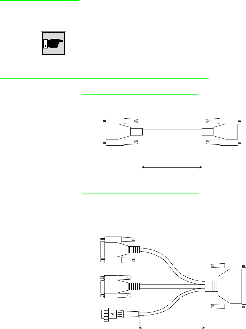
75 / 87l
Appendix A: WIMAN Hardware
8.4 Hybridcable
In the following, all hybrid cables with their appropriate area of
application are described.
Note:
The 37-pin SubD link (female) is always attached to the 37-pin
SubD link (male) of the WIMAN.
8.4.1 Hybridcable used for X21-configurations
Zeromodemcable (NULL-C21-15)
Zeromodemcable for direct connection of 2 WIMAN devices. In
addition a Hybrid cable Type H4 is needed.
female
14 x 0,15 mm², shielded,
UV-resistant
1000 mm
S 15 S 15 female
Hybridcable Type1 (H1-X21C-37)
This hybrid cable is used with indoor installations and provides
the power connection, a direct link for a Frame Relay capable
Router as well as a configuration interface (RS-232).
S 37
male
female
11 x 0,15 mm², shielded
3 x 0,15 mm², shielded
5 x 0,15 mm²
female
with nut
300 mm
S 15
DIN Renk,
3
p
in
S 9
female
with nut
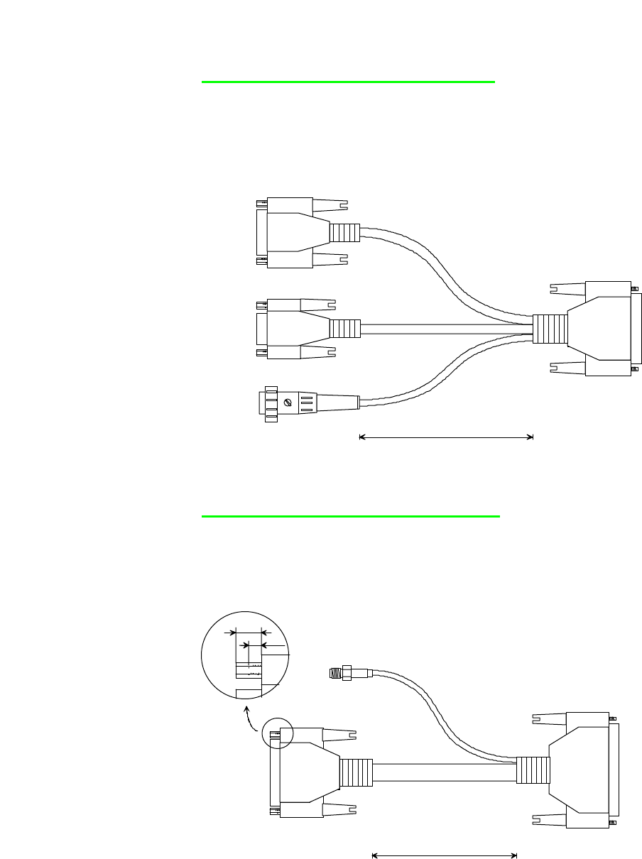
76 / 87
Appendix A: WIMAN Hardware
Hybridcable Type 2 (H2-X21C-25)
This Hybrid cable is being used as an internal termination cable
when installing a WIMAN on a readio-tower on on a rooftop.
The 25pin SubD-plug (male) is connected to the 12x2 Dataca-
ble, which leads from the WIMAN to the Router. All other con-
nectors are the same as on Hybrid cable type 1.
SubD 25
male
S 25
11 x 0,15 mm², shielded
5 x 0,15 mm²
3 x 0,15 mm², shielded
SubD 15
female
with nuts
300 mm
S 15
S 9
SubD 9
female
with nuts
DIN Renk, 3 pin,
180 de
g
rees, male
Hybrid cable Type 3 (H3-X21C-37)
This hybrid cable is attached with outdoor installations between
the WIMAN and the data cable (12x2). The SMA socket serves
for the link to the synchronisation bus, if several WIMAN de-
vices are mounted in direct proximity.
S 37
SubD 37
female
SMA
female
SubD 25
male
with nuts
RG 316
23 x 0,15 mm², shielded, paired
400 mm
S 25
Date: 27. June 2000
2 mm
6 mm
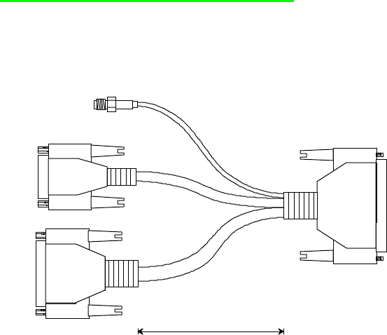
77 / 87l
Appendix A: WIMAN Hardware
Hybrid cable Type 4 (H4-X21C-37)
This hybrid cable is used with a Peer to Peer structure of a re-
mote POP. For this an additional NULL-X21C-15 cable, a syn-
chronisation bus, a data cable (12x2) and a hybrid cable Typ2
becomes necessary (schematic structure see further above.)
S 37
female SMA
male
with nut
female
9 x 0,15 mm², shielded
13 x 0,15 mm²,
shielded
RG 316
400 mm
S 15
S 25
male
with nut
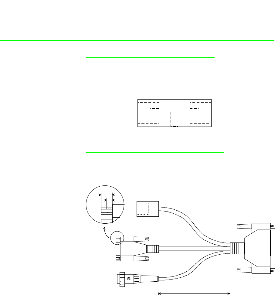
78 / 87
Appendix A: WIMAN Hardware
8.4.2 Hybrid cable when using the IP-routing-functionality
RJ45-Connectionbox (HA-ETH-45)
This link box is attached between the Ethernet cable of the local
network and the hybrid cable H3-eth-37ext. Into the box the cur-
rent supply link of the WIMAN, which is connected to the
power pack, is integrated.
RJ 45
female RJ 45
female
Hybrid cable Ethernet 1 (H1-ETH-37)
This Ethernet hybrid cable is used for indoor installations and
provides the power connection, a direct link to the local network
(over Ethernet cable) and a configuration interface (RS-232).
SubD 37
female
4 x 0,15 mm², shielded, paired
3 x 0,15 mm², shielded
5 x 0,15 mm²
300 mm
DIN Renk, 3 pin,
180 de
g
rees
,
male Date: 10. July 2000
SubD 9
female
with nuts
RJ45,
female
2 mm
6 mm
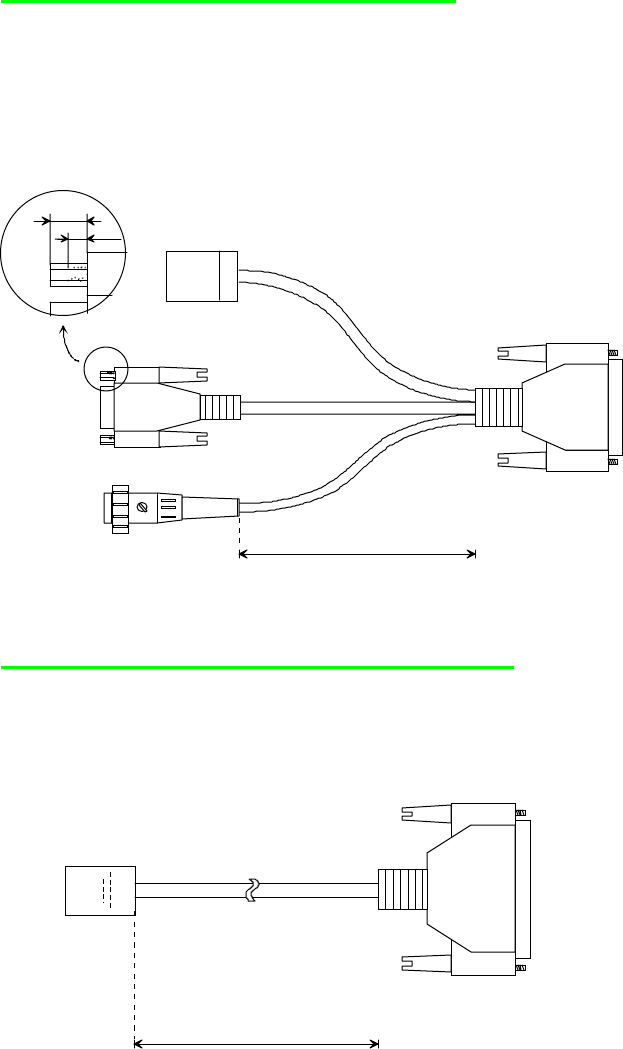
79 / 87l
Appendix A: WIMAN Hardware
Hybrid cable Ethernet 2 (H2-ETH-25)
This hybrid cable is used as internal terminal cable with radio
tower installations or installation of the WIMAN on a rooftop.
The 25-pin SubD (male) link is connected to the data cable
(12x2), which leads from the WIMAN (outdoor) to the inward.
The further interfaces correspond to those of the hybrid cable
Type Ethernet 1.
SubD 25
male
S 25
4 x 0,15 mm², shielded, paired
5 x 0,15 mm²
3 x 0,15 mm², shielded
300 mm
S 9
SubD 9
female
with nuts
RJ45,
female
DIN Renk, 3 pin,
180 de
g
rees
,
male
2 mm
6 mm
Date: 10. July 2000
Hybrid cable Ethernet 3 (H3-ETH-37EXT)
This hybrid cable serves for the link of the WIMAN to the local
Ethernet. The current supply lines of the WIMAN are already
integrated in this cable. This cable can be used only together
with the link port HA-ETH-45.
S 37 SubD 37
female
25 m
RJ45 male
incl. protective cap
Cat 5, STP

80 / 87
Appendix B: Technical data
9 Appendix B: Technical data
Product outline
WIMAN Star, Access high-speed transfer in point-to-
multi-point mode
WIMAN Line flexible point-to-point transfer
Radio
Frequency range 2.400 - 2.4835 GHz
Type of modulation Spread Spectrum Frequency
Hopping 2-FSK, 4-FSK
Number of channels 80, non-overlapping
Wireless interface 1 Mbps, 2-FSK
2 Mbps, 4-FSK
Transmitting power 100 mW (ETSI-Version) (E.I.R.P.)
4 W (FCC-Version)
Transfer capacity 256 KBps @ 2-FSK
512 KBps @ 4-FSK
Max. input-level 0 dBm
Recipient- -94 dBm @ 2-FSK
sensitivity -88 dBm @ 4-FSK
Range up to 5 km (ETSI-Version with pla-
nar array antennas)
up to 25 mi (FCC-Version)
RF-connector SMA plug connector
RF interface
Configurable block-repetition
CRC-based error correction
In-slot acknowledgement
Device-specific data encryption
Data-interface
Synchronous X.21 / V.35 (optional) max. 2 Mbps
81 / 87l
Appendix B: Technical data
Protocols
Point-to-point-mode
Synchronous Transparent (HDLC-
frame structure)
Point-to-Multipoint-mode
Synchronous operation Frame Relay Packet Switching
Antennas
Mobile antenna Omnidirectional 2 dBi
Fixed antennas Omnidirectional 8 dBi
Planar 8.5 dBi
Planar 16 dBi
Paraflector 24 dBi
Mass & weights (without antennas)
WIMAN-device 176 x 110 x 40 mm, 1050 g
Outdoor box 300 x 190 x 85 mm, 2200 g
General
Voltage supply 12 – 26 V =; max. 10 W
110 – 230 V, 50 -60 Hz~
Temperature range -20°C - +55°C
Humidity 100 %, not condensing
IP enclosure IP63, mounted in security housing
Display 3 LEDs, two-colored
Administration
Remote looptest
SNMP-based status-query and error signaling
Network access via TCP / IP, password protected
Software-update via TFTP
Individual bandwidth management
Appendix C: Pin-allocation of the Datacables
82 / 87
10 Appendix C: Pin-allocation of the Data-
cables
10.1 WIMAN Datacable (10 x 2)
Pin Wire color (1. line) Pin Wire color (2. line)
1 White/Grey 14 White/Green
2 - 15 Brown/Green
3 White/Yellow 16 Pink/Brown
4 Yellow/Brown 17 White/Pink
5 White 18 Grey/Pink
6 Brown 19 Red/Blue
7 - 20 -
8 Grey/Brown 21 Black
9 Green 22 Purple
10 Yellow 23 -
11 Pink 24 Red
12 Grey 25 Blue
13
Table 7 WIMAN data cable (10 x 2), pin assortment
Attention:
Provide a correct grounding of the data cable screen.
Paired-wire Wire color Pin number Wire color Pin number
1White 5Brown 6
2Green 9Yellow 10
3Grey 12Pink 11
4Blue 25Red 24
5 Black 21 Purple 22
6 Grey/Pink 18 Red/Blue 19
7 White/Green 14 Brown/Green 15
8 White/Yellow 3 Yellow/Brown 4
9 White/Grey 1 Grey/Brown 8
10 White/Pink 17 Pink/Brown 16
Shield Shield
Table 8 WIMAN data cable (10 x 2) paired-wire assort-
ment
Appendix C: Pin-allocation of the Datacables
83 / 87l
10.2 WIMAN Datacable (12 x 2)
Pin Wire color (1. line) Pin Wire color (2. line)
1 White/Grey 14 White/Green
2 Grey/Brown 15 Brown/Green
3 White/Yellow 16 Pink/Brown
4 Yellow/Brown 17 White/Pink
5 White 18 Grey/Pink
6 Brown 19 Red/Blue
7 White/Blue 20 White/Red
8 Brown/Blue 21 Black
9 Green 22 Purple
10 Yellow 23 Brown/Red
11 Pink 24 Red
12 Grey 25 Blue
13
Table 9 WIMAN data cable (12 x 2) pin assortment
Attention:
Provide a correct grounding of the data cable screen.
Paired-wire Wire color Pin number Wire color Pin number
1White 5Brown 6
2 Green 9 Yellow 10
3Grey 12Pink 11
4 Blue 25 Red 24
5 Black 21 Purple 22
6 Grey/Pink 18 Red/Blue 19
7 White/Green 14 Brown/Green 15
8 White/Yellow 3 Yellow/Brown 4
9 White/Grey 1 Grey/Brown 8
10 White/Pink 17 Pink/Brown 16
11 White/Blue Brown/Blue
12 White/Red Brown/Red
Screen Screen
Table 10 WIMAN data cable (12 x 2) Paired-wire assort-
ment

84 / 87
Appendix D: Alphabetical list of instructions
11 Appendix D: Alphabetical list of instruc-
tions
Instruction Applicable in command
mode starting from
authorization level
Applicable in configura-
tion mode starting from
authorization level
Remarks
<parname> <value> - 1
Checkcfg - 1
Clear 1 1
Clear stat <type> 1 -
Config 1 -
Del config - 1
Del <parname> - 1
Del passwd console - 1
Enable 1 - No help available
Exit 1 - No help available
Export 1 1
Help 1 -
Help <parname> 1 1
Passwd console - 1
Passwd console crypt - 1 No help available
Passwd enable - 1
Passwd enable crypt - 2 No help available
Reset 1 -
Reset config - 1 (configuration password) No help available
Restore - 1
Save 1 -
Show 1 1
Show <regexp> 1 1
Stat <type> 1 1
Swupdate 1
Table 11 alphabetical list of instructions

85 / 87l
Index
12 Index
Will be created later

86 / 87
Index of figures
13 Index of figures
Figure 1 Point-to-Point connection using WIMAN LINE....................................... 10
Figure 2 wireless access networks with WIMAN STAR and WIMAN ACCESS..... 11
Figure 3 Standard Frame Relay applications...................................................... 12
Figure 4 Diagram of the different operating modes ............................................. 15
Figure 6 exported configuration file .................................................................... 28
Figure 7 Help display output .............................................................................. 30
Figure 8 the statistics assistance display............................................................ 31
Figure 9 arrangement of equipment for the configuration of the WIMAN radio
modem......................................................................................... 34
Figure 10 Frame Relay connections with the WIMAN ........................................ 58
Figure 11 Simple WIMAN Network with CISCO-Router...................................... 62
Figure 12 front side of the WIMAN radio modem ............................................... 70
Figure 13 rear side of the WIMAN radio modem ................................................ 70

87 / 87l
Index of tables
14 Index of tables
Table 1 parameters of an extended point-to-point connection (connection 1) ..... 54
Table 2 parameter of an extended point-to-point connection (connection 2)....... 54
Table 3 Structure of the 2 Byte long address array............................................ 59
Table 4 NodeId with 2-Byte-Frame Relay address array.................................... 60
Table 5 DLCI allocation in connection with 2-Byte-address array....................... 61
Table 6 bit sequence for different DLCI identifiers ............................................. 61
Table 7 WIMAN data cable (10 x 2), pin assortment.......................................... 82
Table 8 WIMAN data cable (10 x 2) paired-wire assort-ment ............................. 82
Table 9 WIMAN data cable (12 x 2) pin assortment........................................... 83
Table 10 WIMAN data cable (12 x 2) Paired-wire assortment ........................... 83
Table 11 alphabetical list of instructions........................................................... 84