WIMAN Systems WIMAN2A24 FHSS RF Modem User Manual Introduction to WIMAN technology
WIMAN Systems Inc FHSS RF Modem Introduction to WIMAN technology
Contents
Manual6

51 / 90l
4 Hardware Installation
- All data cables (upper and lower end)
- All small external housings (if used)
- All antennas on large external housings (if used)
- the radio modem designated as synchronization mas-
ters, with the additional designation "Sync master",
4.3 Installation at the Radio Tower
4.3.1 Installing the tower standoff at the radio mast
4.3.2 Installing the WIMAN hardware at the tower standoff
Attach the WIMAN hardware (external housing and antennas)
to the tower standoff at the suitable positions and align. If a
WIMAN is to take over the function of the synchronization-
master and is not clocked from a remote location, always use the
unit aligned to the north (0º) as the synchronization master.
4.3.3 Installation
Install all data cables. Connect the data cables with the Hybrid
cables coming from the WIMAN radio modems.
Attention:
For correct function and error-free installation, be sure that the
sync cable is installed before testing.
4.3.4 Start tests
Now test all installed components on correct function and instal-
lation. You find a specification of the tests in chapter 6 on
page 58.
4.3.5 Checking the antenna adjustment
• Check to see that all antennas are facing the correct direc-
tion.
• Note the adjustments of all antennas.
4.3.6 Test all devices
• Make sure all devices on the radio tower are switched on
and are connected to the synchronization cable.
• Test each WIMAN radio modem again (see chapter 6,
page 58.) to make sure that there is no error caused by the
synchronization cable.

52 / 90
4 Hardware Installation
4.3.7 Save all configuration data of the WIMAN radio mo-
dems at the radio tower
• Use the same name conventions used for the cables and
WIMAN radio modems.
• Record the following information with a terminal program:
- Parameter („show“-command)
- Statistics („stat“-command)
4.4 Grounding
It is extremely important to ground all installed devices on the
radio tower. This will reduce the amount of damage should
lightning strike. The following steps will also help to reduce
possible damage caused by lightning:
• Do not mount the WIMAN at the highest point of the radio
tower. This is the point most likely to be struck by light-
ning.
• Check that the outdoor housing and the tower standoffs
form a well-grounded metal-on-metal connection with the
tower frame.
• Avoid using rubber washers or seals.
• Install lightning protection devices between the data cable
and the hybrid-sets on both the top and bottom of the tower.
• Ground the data cable to the tower at (a minimum of) three
different places. (1) to the center of the tower, (2) to the
base of the tower where the cable bends (before the bridge
from the tower to the shed) and (3) before the cable runs
into the equipment shed. The best way to do this is to strip
away the outer casing of the cable and affix a grounding
clamp to the cable shielding, then connect this clamp to a
second one which is fixed to the tower.
• Make sure that all equipment (Switches, Routers, etc.) at the
base of the tower is properly grounded to the rack in which
it is mounted. Also make sure that the rack itself is properly
grounded.

4 Hardware Installation
53 / 90l
4.5 Burst-Synchronisation
Burst-synchronization is the coordination process of frequency
hopping tables, receipt, and points of transmitting time for sev-
eral WIMAN networks within the same geographical area.
Burst-synchronization is achieved by both hardware and soft-
ware items. The hardware item is a synchronization cable, which
is only a wire, which connects the X.21-interfaces among them-
selves.
For the X.21 Interface, the synchronization cable is enclosed in
the hybrid cable type 3. This is connected to further radio mo-
dems with additional cables and special T-connectors.
The software section for synchronization consists of the parame-
ter SyncMode, which is to be entered in the basic configuration
of a master or a Slave.
One master radio modem (STAR or LINE) is determined as
synchronization master for all radio modems at that location.
The synchronization master is adjusted as follows:
• SyncMode = Master
All further master radio modems should be adjusted as follows:
• SyncMode = Slave
4.6 Extended Point-to-Point Connections
An estendet Point-to-Point connection can be structured by ar-
ranging two WIMAN LINE “back-to-back”. For this applica-
tion, additional hardware is necessary. Please contact your
WIMAN supplier.
For an extended point-to-point connection the parameter
SyncMode has to be set to the base WIMAN LINE configura-
tion.
The example configurations specified below refer to an ex-
tended X.21 Point-to-Point-connection. In this structure, the
WIMAN LINE Slave 1 is coupled to the WIMAN LINE Master
2.

4 Hardware Installation
54 / 90
Line Master 1 Line Slave 1
NetId = 1 NetId = 1
NodeId = 0 NodeId = 1
Destination = 1 Destination = 0
SyncMode = (according to local Network) SyncMode = Master
Table 1 parameters of an extended point-to-point
connection (connection 1)
Line Master 2 Line Slave 2
NetId = 2 NetId = 2
NodeId = 0 NodeId = 1
Destination = 1 Destination = 0
SyncMode = Slave SyncMode = (according to local Network)
Table 2 parameter of an extended point-to-point
connection (connection 2)
5 Reception quality and transmission speeds
55 / 90l
5 Reception quality and transmission speeds
For the examination of the receipt quality as well as to error de-
tection, test loops can be generated. The type of test loop can be
influenced by the configuration of the parameters LoopData,
LoopMode and LoopTest.
The parameter LoopData enables the setting of the Byte-values
that are to be generated (see page 18). This parameter can be
produced on a WIMAN ACCESS only.
The parameter LoopTest enables a switching to a test loop, with
which the data, which can be transmitted, is produced independ-
ently by the WIMAN radio modem (see page 19).
This test loop can already be activated in the lowest authoriza-
tion level and is, in combination with the statistics analysis on
the wireless interface, an outstanding inspection procedure for
radio communication.
The parameter LoopMode determines, which bit pattern will be
transferred with the back loop in the loop test operation from the
WIMAN radio modem (see page 18)
Attention:
If the back loop test is execute in an operating radio net, avoid
all values except normal. Use of any other value may result in
loss of performance.
5.1 Configuration of a TestLoop with Independently
Generated Data Communication
1. Access the command line level of authorization level one
(see chapter 2 on page 13) and change into the configura-
tion mode. You will see an output similar to:
WIMAN-II (config) >
2. Type in the command looptest true.
3. Check with show looptest the value for the parameter
Looptest. This should now be switched to true. The follow-
ing output appears:
WIMAN-II (config) > show looptest
LoopTest false ( true)
The present and the new configuration (in parentheses) of
the parameter are displayed.

5 Reception quality and transmission speeds
56 / 90
4. To take over the modifications into the current configura-
tion leave the configuration mode by entering the command
exit (see page 27).
The following output appears:
Configuration changed, do you want to save (y)es
/ (n)o / (c)ancel ?
You now have the choice:
- To transfer the new configuration into the current con-
figuration and to leave the configuration mode by
pressing the key „y“,
- To discard the modification but to leave the configura-
tion mode anyway by pressing the key „n“ or
- To not take over the modification into the current con-
figuration but to stay in configuration mode by press-
ing the key „c“.
Press the „y“ key to activate the looptest. The modification
of the parameter becomes part of the current configuration
and the WIMAN starts transmitting bit samples.
5.2 Test after a Radio Tower Installation with Syn-
chronisation
After all devices are correctly installed, a final test must be exe-
cuted. This final test checks if all devices are installed correctly
and whether a trouble free transmitting and receiving mode is
possible.
• Switch on the first WIMAN radio modem. Always begin
with the WIMAN determined as synchronization master.
• Radio test
- If the synchronization Master is a WIMAN STAR or a
WIMAN LINE Master, conduct a loop back test from
a properly configured WIMAN ACCESS or LINE
Slave.
- It the synchronization Master is a LINE Slave, conduct
a loop back test from its LINE Master.
• Check the X.21-interface by connecting the X.21-plug of
the Hybrid cable type-2 to the Router.

5 Reception quality and transmission speeds
57 / 90l
- For the WIMAN STAR enter the commands „stat wl“
and „stat wl<nodeID>“ to ensure proper functioning of
the data exchange.
- For the WIMAN LINE enter the command „stat sync“
to check the setting of both signals (both signals have
to be set to „On“).
5.2.1 Continue the Tests
• Switch on the WIMAN radio modem next to the synchroni-
zation master.
• Switch off the synchronization master.
• Perform a reception test.
• Check the X.21-interface (see chapter X.21-Test above).
• Switch the synchronization master back on.
• Perform another reception test to make sure the synchroni-
zation cable does not produce any errors (the radio statistics
should not differ substantially from the preceding ones).
5.2.2 Test the Remaining Modules
• Switch on the next WIMAN.
• Switch off all WIMAN radio modems that were tested be-
fore.
• Perform a reception test.
• Check the X.21-interface (see chapter X.21-Test above).
• Switch on all WIMAN units that were tested before.
• Connect the synchronization cable to the last tested
WIMAN radio modem.
• Perform another reception test to make sure the synchroni-
zation cable does not produce any errors (the radio statistics
should not differ substantially from the preceding ones).
5.3 Transmission Speeds
5.3.1 FTP-Download from an FTP-Server
The maximum transmission speed of the WIMAN radio modem
at optimum conditions is about 25 … 30 Kbytes/s at 2FSK and
about 55 … 62 Kbytes/s at 4FSK (depending on the extend of
utilization of the network).
58 / 90
6 Frame Relay
6 Frame Relay
6.1 Technical Description of the Frame of Relay Fea-
tures
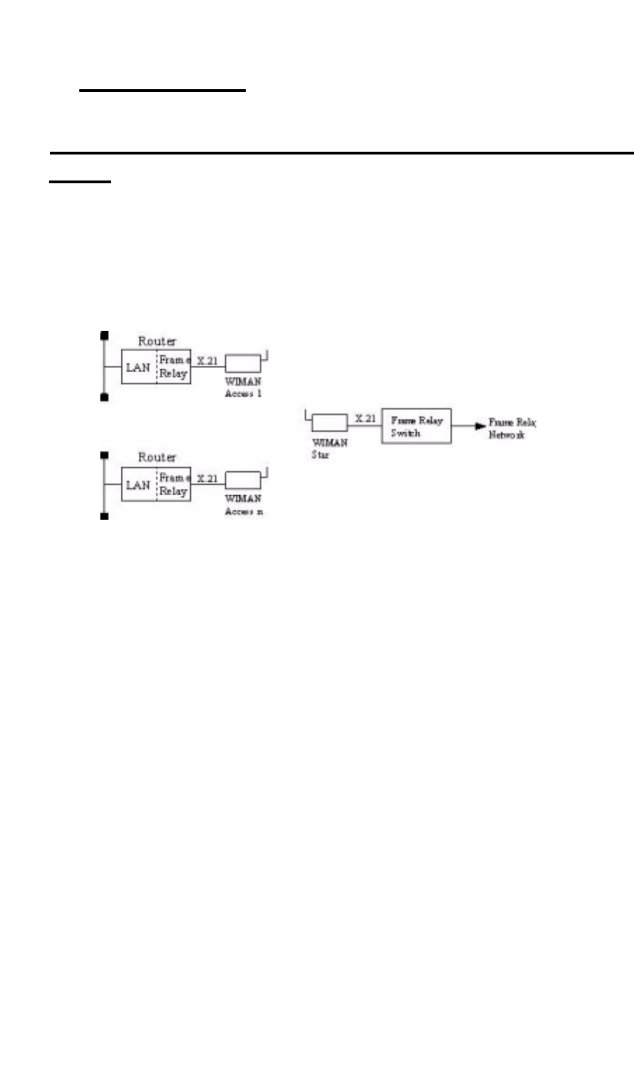
The WIMAN STAR supports the multiplexing of Frame Relay
packages. In multiplexing procedure, the packages received
from the Frame Relay Switches are transferred to the WIMAN
ACCESS, which is connected to a Frame Relay Router at the
user’s site.
Figure 10 Frame Relay connections with the WIMAN
For addressing the WIMAN ACCESS the DLCI number (Data
Link Connection Identifier) of the Frame of Relay protocol is
used.
The following restrictions apply to the Frame Relay support:
• Only static connections are supported (PVC = Permanent
Virtual Connection)
• DLCI numbers must be configured statically on the Frame
Relay Switch and the Frame Relay Router
• 2-, 3- or 4- Byte-Frame Relay-address-arrays are supported,
• Since the WIMAN node address is embedded in the DLCI
number (10-bit DLCI with implemented WIMAN node
identifier), the DLCI allocation of numbers is reduced
• Up to four virtual connections are supported for each Frame
Relay user
• Up to 250 Frame Relay users are supported at a WIMAN
STAR (currently 9 users possible, Software Version T0.7).
• The following Frame of Relay features are not supported:

59 / 90l
6 Frame Relay
- LMI (Local Management Interface of ITU-T Q.933 or
ANSI T1.617), since this procedure uses DLCI 1023 or
DLCI 0,
- Establishing of connections for SVCs (uses DLCI 0),
- Multiple transmissions (uses DLCI 1019 ... 1022).
6.1.1 Frame Relay-Address array
Table 3 shows the structure of the 2 Byte long Address array:
8 7 6 5 4 3 2 1
DLCI 10 DLCI 9 DLC I 8 DLCI 7 DLCI 6 DLCI 5 C/R EA
DLCI 4 DLCI 3 DLCI 2 DLCI 1 FECN BECN DE EA
Table 3 Structure of the 2 Byte long address array
Explanation:
• DLCI
Data Link Connection Identifier
• C/R
Command Response Bit
• EA
Address Array Extension Bit
• FECN
Forward Explicit Congestion Notification
• BECN
Backward Explicit Congestion Notification
• DE
Discard Eligibility Indicator
The node address of the WIMAN is determined by the high or-
der-bits (DLCI 03...DLCI 10) of the DLCI number. The low or-
der bits (DLCI 1...DLCI 2) are used for virtual connections.
2-Byte-Adress
arra
y

60 / 90
6 Frame Relay
The LCI value for the Frame Relay Router of the user is calcu-
lated as follows:
DLCIm = 512 + NodeId * 4 + m m = [0 ... 3]
Table 4 lists the valid DLCI numbers for appropriate node iden-
tifiers (NodeId) on use of the 2-Byte-Frame of Relay address ar-
ray.
WIMAN NodeId DLCI array Note
0 512 – 515 reserved (WIMAN STAR)
1 516 – 519
2 520 – 523
3 524 – 527
4 528 – 531
5 532 – 535
6 536 – 539
7 540 – 543
8 544 – 547
9 548 – 551
10 552 – 555
11 556 – 559
12 560 – 563
13 564 – 567
14 568 – 571
15 572 – 575
Table 4 NodeId with 2-Byte-Frame Relay address array
In the following, the implementation of the Frame of Relay Pro-
tocol within the WIMAN software is listed briefly. Exclusively
the static software-Version of the WIMAN STAR supports the
Frame Relay Protocol with the following characteristics:
• The maximum size of the Frame Relay information field
amounts to 4096 byte.
• The WIMAN star rejects Frame Relay framework with in-
valid DLCI number (transmitter and receiver).
DLCI value
calculation
Frame Relay-
support of the
WIMAN Software

61 / 90l
6 Frame Relay
6.1.2 DLCI-areas when the 2-Byte-Address array is used
(ITU Q.922)
Table 5 lists the allocation of the DLCI numbers on use of the 2-
Byte-address array.
DLCI-area Meaning
0 Signalizing in the transmission channel, if necessary
1 – 15 Reserved
16 – 511 Network option: on not-D channels, usable for the support of user
information
512 - 991 logical connecting identifier for the support of user information (the
use of semi permanent connections can reduce the DLCI numbers
available within this area)
992 - 1007 Layer 2-Management of Frame-transport services
1008 reserved
1023 Layer 2-Management in the transmission channel if necessary (only
usable without d-channel)
Table 5 DLCI allocation in connection with 2-Byte-
address array
DLCI Range 10 9 8 7 6 5 4 3 2 1
0 0 0 0 0 0 0 0 0 0 0
1 - 0 0 0 0 0 0 0 0 0 1
15 0 0 0 0 0 0 1 1 1 1
16 - 0 0 0 0 1 0 0 0 0 0
511 0 1 1 1 1 1 1 1 1 1
512 - 1 0 0 0 0 0 0 0 0 0
911 1 1 1 1 0 1 1 1 1 1
992 - 1 1 1 1 1 0 0 0 0 0
1007 1 1 1 1 1 0 1 1 1 1
1008 - 1 1 1 1 1 1 0 0 0 0
1022 1 1 1 1 1 1 1 1 1 0
1023 1 1 1 1 1 1 1 1 1 1
Table 6 bit sequence for different DLCI identifiers
62 / 90
6 Frame Relay
6.2 Frame Relay-configuration samples
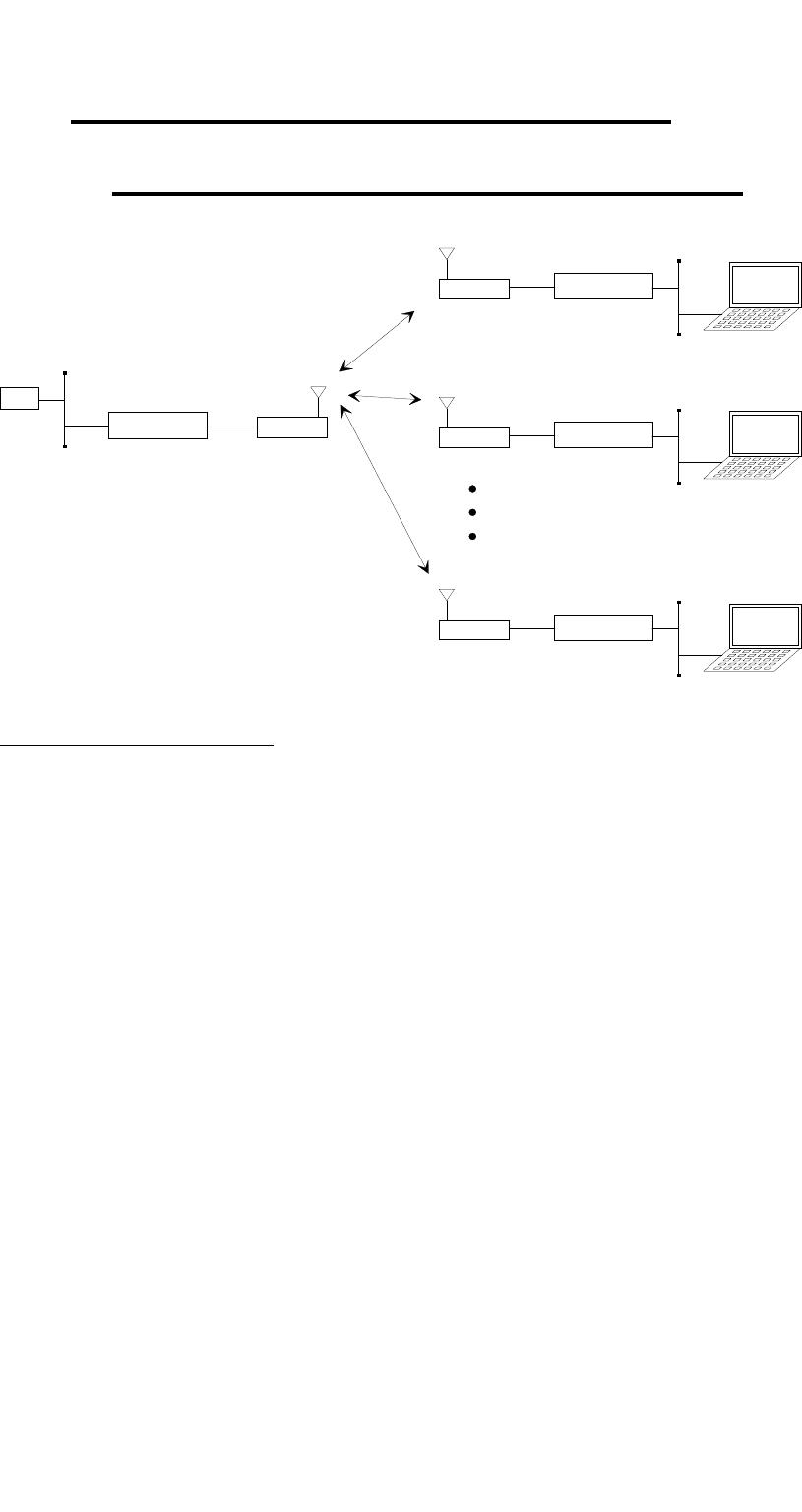
6.2.1 Sample configuration with CISCO-Routers
Star
Access 1
Cisco 1005
Cisco 1005 Service-
Notebook
GW
192.168.33.0 /24
.3
.20 .1 .2 (515)
.3 (519)
192.168.40.128 /29
.129
.130
.34
(515)
.33
(515)
Access 2 Service-
Notebook
.4 (523)
192.168.40.136 /29
.137
.138
.38
(515)
.37
(515)
Access 9 Tiny Router Service-
Notebook
.11 (519)
192.168.40.240 /29
.195
.194
.66
(515)
.65
(515)
Cisco 1005
D 516
D 520
Figure 11 Simple WIMAN Network with CISCO-Router
CISCO1, connected to STAR unit:
! Configuration Cisco Star
!
no service password-encryption
no service udp-small-servers
no service tcp-small-servers
!
hostname Cisco_Master
!
enable password wiman
!
ip subnet-zero
!
interface Ethernet0
ip address 192.168.33.20 255.255.255.0
!
interface Serial0
no ip address
encapsulation frame-relay IETF
no keepalive
no fair-queue
!
interface Serial0.1 multipoint
ip address 192.168.40.1 255.255.255.224
no arp frame-relay
frame-relay map ip 192.168.40.2 515
frame-relay map ip 192.168.40.3 519
frame-relay map ip 192.168.40.4 523
frame-relay map ip 192.168.40.5 527

63 / 90l
6 Frame Relay
frame-relay map ip 192.168.40.6 531
frame-relay map ip 192.168.40.7 535
frame-relay map ip 192.168.40.8 539
frame-relay map ip 192.168.40.9 543
frame-relay map ip 192.168.40.10 547
frame-relay map ip 192.168.40.11 551
!
interface Serial0.2 point-to-point
ip unnumbered Ethernet0
no arp frame-relay
no cdp enable
frame-relay interface-dlci 516
!
interface Serial0.3 point-to-point
ip unnumbered Ethernet0
no arp frame-relay
no cdp enable
frame-relay interface-dlci 520
!
interface Serial0.10 point-to-point
ip unnumbered Ethernet0
no arp frame-relay
no cdp enable
frame-relay interface-dlci 548
!
ip classless
ip route 0.0.0.0 0.0.0.0 192.168.33.3
ip route 192.168.40.32 255.255.255.252 Serial0.2
ip route 192.168.40.128 255.255.255.248 Serial0.2
ip route 192.168.40.36 255.255.255.252 Serial0.3
ip route 192.168.40.136 255.255.255.248 Serial0.3
ip route 192.168.40.64 255.255.255.252 Serial0.10
ip route 192.168.40.192 255.255.255.248 Serial0.10
!
line con 0
exec-timeout 0 0
line vty 0 4
exec-timeout 0 0
password wiman
login
!
end
CISCO2, connected to ACCESS01:
! Configuration Cisco Access 01
!
no service password-encryption
no service udp-small-servers
no service tcp-small-servers
!
hostname Cisco_Access_01
!
enable secret 5 $1$9xE0$1jVP/hVttHmwhWi/b1Dzv0
!
ip subnet-zero
!
interface Ethernet0

64 / 90
6 Frame Relay
ip address 192.168.40.129 255.255.255.248
!
interface Serial0
no ip address
encapsulation frame-relay IETF
no keepalive
!
interface Serial0.1 point-to-point
ip address 192.168.40.33 255.255.255.252
no arp frame-relay
no cdp enable
frame-relay interface-dlci 515
!
interface Serial0.2 point-to-point
ip unnumbered Ethernet0
no arp frame-relay
no cdp enable
frame-relay interface-dlci 516
!
ip classless
ip route 0.0.0.0 0.0.0.0 Serial0.2
no cdp run
!
line con 0
exec-timeout 0 0
line vty 0 4
exec-timeout 0 0
password wiman
login
!
end
Configuration STAR:
## WIMAN II configuration file
#
# Air
Antenna 8mn360
MaxNodeId 1
MaxRetry 9
NetId 250
RadioPower Normal
# Serial
ConBaudrate 9600
ConDataBit 8
ConHandShake Soft
ConPageSize 24
ConParity None
ConStopBit 1
PS1 WIMAN_Star
SerBaudrate 2048000
SerCRC 16
SerEncode NRZ
# Network
IPDefaultGW 192.168.40.1
IPEthAddress 0.0.0.0
IPEthMask 255.255.255.0

65 / 90l
6 Frame Relay
IPSerAddress 192.168.40.2
IPSerMask 255.255.255.224
IPTFTPServer 192.168.33.178
Location Area_01
# Sync
SyncMode Off
passwd enable crypt Av/WbhGC.i1HA3E
Configuration ACCESS01:
## WIMAN II configuration file
#
# Air
Antenna 8mn360
LoopData FF
LoopMode Long
LoopTest False
MaxRetry 9
NetId 250
NodeId 1
RadioPower Normal
# Serial
ConBaudrate 9600
ConDataBit 8
ConHandShake Soft
ConPageSize 24
ConParity None
ConStopBit 1
SerBaudrate 2048000
SerCRC 16
SerEncode NRZ
# Network
IPDefaultGW 192.168.40.1
IPEthAddress 0.0.0.0
IPEthMask 255.255.255.0
IPSerAddress 192.168.40.34
IPSerMask 255.255.255.252
IPTFTPServer 192.168.33.178
IPWLAddress 192.168.40.3
IPWLMask 255.255.255.224
Location Area_1
# Sync
SyncMode Master
passwd enable crypt Av/WbhGC.i1HA3E

7 Troubleshooting
66 / 90
7 Troubleshooting
7.1 Techniques and Methodologies Used for Trou-
bleshooting
7.1.1 General Problems
This section lists some common problems that may occur and
cause a malfunction in the WIMAN system:
Bad RF-Link between STAR (Master) and ACCESS (Slave):
• STAR units are not synchronized ! see stat sync
• Bad hardware on the STAR or the ACCESS
- Check RF statistics from the STAR to other ACCESS de-
vices ! see stat wl ext
If all other connections are functioning properly,
STAR is not defective.
• If the star is working correctly consider the following ques-
tions:
- Is the ACCESS device configured correctly (correct STAR,
correct sector)?
- Are there any obstacles between the STAR and the
ACCESS?
- Is the antenna cable attached correctly?
- Is the antenna adjustment correctly?
- Is the ACCESS device itself defective (defective transmit-
ting or receiving part)? ! If so, exchange the device.
- Are two ACCESS devices within a network configured with
the same NodeID? Check the ACCESS configuration, the
network configuration and the documentation of the other
ACCESS radio modems within in the same network.
No data communication from the STAR to the ACCESS:
• Check the radio connection between the ACCESS and the
STAR.
• Check the wiring of the STAR and ACCESS
- Check the other radio modems attached to this STAR
If data can be transmitted to the other ACCESS de-
vices then the wiring at the STAR is OK.

7 Troubleshooting
67 / 90l
If you are still uncertain whether there is a problem
with the wiring of the STAR, proceed as follows:
Check the statistics with the commands stat serial ext
and stat wl<NodeID>. If you transmit a Ping, the
Rx and Tx-counter should be increased.
Check whether the data cable is wired according to the
specifications shown in chapter 10, page 85.
Check all modules for correct wiring.
Check the hybrid cables.
Check the interface converters.
Check the cross over cables.
- Check the wiring on the ACCESS:
Check the statistics with the commands stat serial ext
(see page 49) at the ACCESS-side. If you transmit
a Ping, the Rx and Tx-counters should increase.
Check whether the data cable is wired according to the
specifications shown in chapter 10 on page 85.
Check the wiring of all modules.
Check the hybrid cables.
Check the routing tables.
• With the instruction stat hw compare the serial number en-
tered in the device table (peer-table) with the actual serial
number of the device. If the serial number does not match,
all data packages will be discarded. Enter the following to
delete an existing entry in the device table:
PEER <NodeID> <ENTER>
Afterwards reset the device.
• Check whether the looptest at the ACCESS radio modem is
still active (show looptest). The Parameter „LoopTest“ must
be set to „false“.
• Defective Router at the customer side:
- Check the configuration
- Check the Hardware
• PVC
- PVC was built on the wrong port
- PVC was built with wrong DLCI (according to the appro-
priate NodeID of the ACCESS)
• Routing tables

7 Troubleshooting
68 / 90
• Bad port on the switch
- Check other customers who are attached to the same STAR
- In case no further customers are attached to the same
STAR, try attaching the device to another port.
WIMAN Baud rate parameters are not adjusted correctly:
If the WIMAN radio modem does not interface with the termi-
nal program, the Baud rate may be set incorrectly on the
WIMAN and/or the terminal program.
Frequency table adjusted incorrectly
If the WIMAN Slave cannot construct synchronized connections
and you are using generated frequency tables, check that the pa-
rameter "FtabMode" is adjusted to "user". Make sure that all
parameters are configured correctly.
Parameter destination not adjusted correctly (LINE only)
This situation cannot occur after a loop test. If the Socket pro-
gram cannot structure a connection, check the network and en-
sure that all parameters "destination" are set to the correct value.
Baud rate in the Socket program not set correctly
If the Socket program cannot construct a connection, it could be
that the Baud rate is set incorrectly on the Socket program
and/or the WIMAN.
Parameter NodeID not set correctly
If an ACCESS radio modem receives synchronization impulses,
but no data can be transmitted, it could be that the parameter
NodeID is adjusted incorrectly. The double assignment of a
node number in the same network leads to malfunctioning.
Serial number does not correspond with the device table
(Peertable)
If the WIMAN STAR is adjusted to a serial number that differs
from the one used in the Peertable, malfunction may occur.
IP-Parameter in the Socket-program not set properly
If the Socket program over the ACCESS radio modem cannot
construct a connection, check whether all IP parameters are ad-
justed correctly.
Damaged or defective antenna cable
Damaged or defective synchronization cable

7 Troubleshooting
69 / 90l
Any of these problems may lead to poor or no radio communica-
tion. Check the antenna cables for damages. If there are no dam-
ages, check the synchronization connection. If the problem per-
sists, the WIMAN may need to be replaced.
7.1.2 Troubleshooting with Radio Tower Installations
• If the WIMAN radio modem can not be accessed over the
RS-232-interface, the problem may be caused by:
- A non-corresponding Baud rate of the terminal program and
the WIMAN (usually the Baud rate is adjusted to 9600
Baud)
- Incorrectly attached cables
- Faulty Hybrid-2 or Hybrid-3-cables. Exchange the Hybrid-
2-cable first and then the Hybrid-3-cable (if necessary).
- Faulty contacts inside the data cable plug. Check the con-
figuration and transmission with an extra 25pin data ca-
ble.
• In case the ACCESS can get no RF-synchronization signal
(indicated by the Status-LED at the front side of the unit) or
if the synchronization signal reception is periodically inter-
rupted, the problem may be caused by:
- Incorrect configuration of the ACCESS or STAR. Check
whether all parameters are correct.
- The operating voltage at the star radio modem is too low. If
the operating voltage at the WIMAN radio modem drops
below the given threshold value, a restart is performed
automatically. It is advisable to constantly apply a volt-
age at the radio modem by at least 12V.
- Defective or unattached antenna cable,
- A Faulty Hybrid-2 or Hybrid-3-cable. Replace the Hybrid-
2-cable first and then the Hybrid-3-cable (if necessary).
- Defective RF filters.
- Defective WIMAN STAR or ACCESS.
- Faulty contacts inside the data cable plug. Check for perfect
configuration and transmission with an additional 25pin
data cable.
- Defective synchronization cable (short-circuit in the plug)
of and to the testing device.
- Defective T-connector (short-circuit)
70 / 90
Appendix A: WIMAN Hardware
8 Appendix A: WIMAN Hardware
!!!!!!!!!!Still being revised!!!!!!!!!!!!.
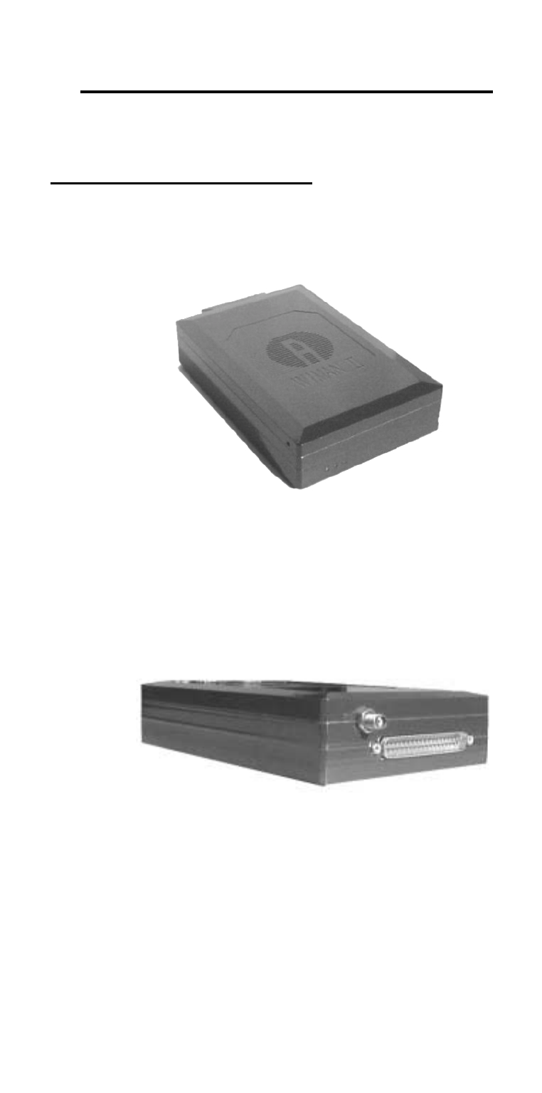
8.1 Technical description
Below you will find pictures of the WIMAN units:
Figure 12 front side of the WIMAN radio modem
Figure 13 rear side of the WIMAN radio modem