WIMAN Systems WIMAN2A24 FHSS RF Modem User Manual Introduction to WIMAN technology
WIMAN Systems Inc FHSS RF Modem Introduction to WIMAN technology
Contents
Manual02
WIMAN Star
WIMAN Access
WIMAN Line
Operation Manual
Software Version: T0.7
- Version E 17 -
August 18th, 2000
ALTVATER AIRDATA Systems GmbH & Co. KG
Riemenstr. 30, 74906 Bad Rappenau
Tel.: 07264/804-0
Fax: 07264/804-209
Email: wiman.support@altvater.com
WWW: http://www.altvater.com
DRAFT

Distribution and/or duplication of any materials belonging to
this product is prohibited except with explicit written permission
from Airdata WIMAN Systems, Inc. All information was gener-
ated after careful research and testing.
Subjects to change without notice.
Bad Rappenau, July 2000
The actual version of this operation manual can be found at
http://www.wiman.net.
Windows is a registered trademark of Microsoft Corporation. Cisco is a
registered trademark of Cisco Systems Inc. Other products mentioned in this
manual might be registered trademarks of the respective manufacturer.
FCC-Information:
FCC ID: NB9WIMAN2A24
This Device complies with Part 15 of the FCC-Rules.
Operation is subject to the following two conditions:
(1) This device may not cause harmful interference, and
(2) This device must accept any interference received,
including interference that may cause undesired operation.
Caution !
Exposure to Radio Frequency Radiation
The radiated output power of the equipment is below the FCC ra-
dio exposure limits. Nevertheless, it is advised to use the equip-
ment in such manner that the potential for human contact during
normal operation is minimized.
Any changes or modifications not in accordance with the instruc-
tions may void the user’s authority to operate the equipment.
The WIMAN unit does not contain any user serviceable parts in-
side and should not be opened by anyone other than authorized
service personnel.
Configuration and installation shall be performed by personnel
being familiar with the WIMAN system only. Improper configura-
tion may void the right to operate WIMAN units. For more infor-
mation, please refer to chapter 2.5.1 of this manual.
Conventions
This operation manual uses the following conventions:
Symbols:
Danger!
This symbol is intended to warn the user that improper use of
the instruments could result in injury.
Information
This symbol is intended to draw the user’s attention to useful in-
formation.
Note
This symbol is intended to alert the user to information that may
save time or simplify a task.
Attention
This symbol is intended to indicate specific directions and
methods necessary for proper operation.
Checklist
This symbol is intended to inform the user of the required steps
to complete a task.
Texts:
Commands are shown in italics and bold typeface.
Parameters are shown in italics.
Display outputs are shown in Courier.
Keys and names of Menu windows are shown in bold typeface.

Table of Contents
4 / 90
Table of Contents
1 Introduction to WIMAN technology ..............................................................................................................7
1.1 Transmission Speeds / Frequency Range.............................................................................................8
1.2 Frequency Hopping Procedure.............................................................................................................9
1.3 WIMAN Network Topology..................................................................................................................9
1.4 Basic WIMAN Topologies...................................................................................................................10
1.4.1 Point-to-Point connections with WIMAN LINE ...........................................................................10
1.4.2 Cellular Networks using WIMAN STAR and WIMAN ACCESS................................................11
1.5 Transmission Protocols .......................................................................................................................12
1.5.1 Frame Relay...................................................................................................................................12
2 The WIMAN Command Line Level .............................................................................................................13
2.1 Authorization Levels............................................................................................................................13
2.2 Passwords .............................................................................................................................................14
2.3 Operation Modes..................................................................................................................................15
2.4 Configuration Data..............................................................................................................................16
2.5 Configuration Parameters...................................................................................................................17
2.5.1 Parameter for the Wireless Interface..............................................................................................17
2.5.2 Parameter for the Serial Configuration Interface ...........................................................................21
2.5.3 Parameter for the serial data Interface ...........................................................................................22
2.5.4 Network-Parameter........................................................................................................................23
2.5.5 Other Parameter .............................................................................................................................25
2.6 Instructions...........................................................................................................................................25
2.6.1 Instructions for the manipulation of Passwords and Authorization Levels....................................25
2.6.2 Instructions for manipulating and transferring of Configuration Data...........................................26
2.6.3 General instructions .......................................................................................................................30
2.6.4 Statistics Instructions .....................................................................................................................31
3 Configuration of the WIMAN radio modem................................................................................................33
3.1 Access to the Command Line Level over the Wireless Interface.....................................................33
3.2 Access to the Command Line Level over the RS-232 Interface.......................................................34
3.3 Access to the command line prompt via the X.21-interface .............................................................36
3.4 Setting of the Parameters of the Differnt Interfaces.........................................................................36
3.4.1 Setting of the Parameters for the Wireless Interface......................................................................36
3.4.2 Setup of the Parameter of the serial interfaces...............................................................................39
3.4.3 Setup of the network parameter .....................................................................................................39
3.4.4 Setup of the other parameters.........................................................................................................40
3.5 Modification of the WIMAN Passwords............................................................................................40
3.5.1 Setting of a Password for the Authorization Level one (console)..................................................40
3.5.2 To delete a Password for the Authorization Level one ..................................................................41
3.5.3 Setting of a Password for Authorization Level two (Enable) ........................................................42
3.5.4 Deletion of a password of the authorization level two (Enable) ....................................................43
4 Hardware Installation...................................................................................................................................44
4.1 Installation instructions for the WIMAN Access-radio modem ......................................................44
4.1.1 Setup of the WIMAN radio modem with Indoor-Set.....................................................................44
4.1.2 Setup of the Outdoor-Set ...............................................................................................................45

Table of Contents
5 / 90l
4.1.3 Required material ..........................................................................................................................45
4.1.4 Find a suitable place for the outdoor-set........................................................................................46
4.1.5 First Reception Test....................................................................................................................... 47
4.1.6 Installation of the Attachment Set and the Outdoor Housing ........................................................47
4.1.7 Second Reception Test .................................................................................................................. 48
4.1.8 Installation of the data cable..........................................................................................................48
4.1.9 Mounting of the DB25-plug interfaces at the inside end of the data cable....................................48
4.1.10 Final reception test with installed data cable................................................................................. 49
4.1.11 Check the statistics of the X.21-interface ......................................................................................49
4.2 Installation of a WIMAN Star............................................................................................................50
4.2.1 Additional necessary components .................................................................................................50
4.2.2 Preparation.....................................................................................................................................50
4.3 Installation at the Radio Tower..........................................................................................................51
4.3.1 Installing the tower standoff at the radio mast...............................................................................51
4.3.2 Installing the WIMAN hardware at the tower standoff .................................................................51
4.3.3 Installation.....................................................................................................................................51
4.3.4 Start tests .......................................................................................................................................51
4.3.5 Checking the antenna adjustment.................................................................................................. 51
4.3.6 Test all devices ..............................................................................................................................51
4.3.7 Save all configuration data of the WIMAN radio modems at the radio tower ..............................52
4.4 Grounding ............................................................................................................................................52
4.5 Burst-Synchronisation.........................................................................................................................53
4.6 Extended Point-to-Point Connections................................................................................................53
5 Reception quality and transmission speeds..................................................................................................55
5.1 Configuration of a TestLoop with Independently Generated Data Communication ....................55
5.2 Test after a Radio Tower Installation with Synchronisation...........................................................56
5.2.1 Continue the Tests ......................................................................................................................... 57
5.2.2 Test the Remaining Modules.........................................................................................................57
5.3 Transmission Speeds ...........................................................................................................................57
5.3.1 FTP-Download from an FTP-Server .............................................................................................57
6 Frame Relay..................................................................................................................................................58
6.1 Technical Description of the Frame of Relay Features....................................................................58
6.1.1 Frame Relay-Address array...........................................................................................................59
6.1.2 DLCI-areas when the 2-Byte-Address array is used (ITU Q.922).................................................61
6.2 Frame Relay-configuration samples ..................................................................................................62
6.2.1 Sample configuration with CISCO-Routers ..................................................................................62
7 Troubleshooting............................................................................................................................................66
7.1 Techniques and Methodologies Used for Troubleshooting..............................................................66
7.1.1 General Problems ..........................................................................................................................66
7.1.2 Troubleshooting with Radio Tower Installations ..........................................................................69
8 Appendix A: WIMAN Hardware..................................................................................................................70
8.1 Technical description ..........................................................................................................................70
8.2 Antenna systems ..................................................................................................................................71
8.3 Hybrid-cable sets .................................................................................................................................75
8.3.1 Standard Connection (Indoor) using Hybrid cable Type 1............................................................ 75
8.3.2 Outdoor Installation using Hybrid cable Type 2 & 3 and Datacable.............................................76
8.3.3 Connection of a remote POP with WIMAN LINE and STAR......................................................77
8.3.4 Connections when using the IP-routing functionality ...................................................................77

Table of Contents
6 / 90
8.4 Hybridcable..........................................................................................................................................78
8.4.1 Hybridcable used for X21-configurations......................................................................................78
8.4.2 Hybrid cable when using the IP-routing-functionality...................................................................81
9 Appendix B: Technical data.........................................................................................................................83
10 Appendix C: Pin-allocation of the Datacables.........................................................................................85
10.1 WIMAN Datacable (10 x 2).................................................................................................................85
10.2 WIMAN Datacable (12 x 2).................................................................................................................86
11 Appendix D: Alphabetical list of instructions..........................................................................................87
12 Index..........................................................................................................................................................88
13 Index of figures.........................................................................................................................................89
14 Index of tables...........................................................................................................................................90

2 The WIMAN Command Line Level
7 / 90l
1 Introduction to WIMAN technology
The WIMAN product series provides a powerful new technol-
ogy for the design of flexible data networks. Integrating a multi-
tude of innovative and optimized methods and communication
protocols, we’ve created a wireless network technology, which
is available for various applications such as campus networking,
high speed access for Internet users, and cellular data networks
in conurbation areas, etc.
In contrast to other available wireless products, the WIMAN
product line integrates the demand for an economic system with
high data rates, a high range and efficient utilization of the fre-
quency-spectrum. The WIMAN System utilizes the most mod-
ern spread spectrum technology without using any further en-
coding algorithm, and features higher security and noise immu-
nity than other existing systems. Applying the frequency hop-
ping technique in combination with an intelligent transmission
control algorithm, the ISM frequency range between 2.4 and
2.4835 GHz is optimally used.
The interfaces provided by the WIMAN unit to attach to the cus-
tomer's terminal equipment complies with the international X.21
and V.24/RS232/RJ45 standards allowing a direct connection to
any standard personal computer, workstation or mainframe sys-
tem. For hooking up wired networks (LAN, MAN, WAN), there
are various routers available in the form of hardware or software
solutions.
The WIMAN product line provides users with the benefits of
high performance and speed in a wireless modem. WIMAN is
easily distinguished from other transmission systems through
several remarkable features:

2 The WIMAN Command Line Level
8 / 90
1.1 Transmission Speeds / Frequency Range
At present, wireless data network technology can be divided into
two categories: The first category consists of wireless modems
with a small transmission bandwidth. These products are used
for company networks, cellular networks, CDPD (Cellular Digi-
tal Packed Data) or GSM (Global System for Mobile communi-
cation) networks. The second category consists of wireless mo-
dems with large bandwidth in the ISM range (Industrial Scien-
tific Media, frequency range around 2,4 GHz), such as wireless
LAN products.
It is possible to cover a large area with the narrow band systems.
Some systems are even able to cover a complete country. The
other LAN products specified above operate with substantially
higher data transmission rates; however, the range of these sys-
tems is limited to approx. 300m/900ft. Therefore, the area of ap-
plication is strongly reduced.
The WIMAN technology offers the advantages of both the nar-
row band systems and the broadband systems. With a clear line
of sight between the antennas, data can be transmitted between
two WIMAN radio modems with a rate of up to 2048 KBit/s (at
the data interface) / 512KBit/sec at the wireless interface in du-
plex operation over a distance of up to approx. 40km/25miles
(FCC version) or up to approx. 5km/3.2miles (ETSI version).
Furthermore, WIMAN systems are deployed in a highly scalable
manner similar in nature to a cellular structure. Therefore, it can
overcome some of the need for direct line-of-sight.

2 The WIMAN Command Line Level
9 / 90l
1.2 Frequency Hopping Procedure
All WIMAN radio modems operate with the modern frequency
hopping procedure. With this procedure, the RF-channel is
changed in very short intervals (all 8 ms). A total of 80 non-
overlapping radio channels are available.
WIMAN takes advantage of these 80 channels, each with 1
MHz of bandwidth, by use of spread spectrum technology (fre-
quency hopping).
The WIMAN radio modem transmits information packages that
hop from one frequency to another, not staying longer than 8 ms
in a frequency range.
As data packets are transmitted and received, the ISP selects the
order of the channels, producing a truly secured line of data.
This remarkable feature yields the following important advan-
tages:
• High security against eavesdropping due to fast changes
of the channel,
• Resistance to jamming,
• Protection against other RF-systems in the same fre-
quency band,
• High performance with high efficiency,
• Possibility of parallel operation of WIMAN connections
by use of different frequency-hopping patterns.
1.3 WIMAN Network Topology
With the WIMAN technology, bonding can be structured in a
simple point-to-point connection, but it is also possible to set up
various other network topologies. The WIMAN product series
consists of three different wireless WIMAN radio-modems:
WIMAN STAR: wireless base station for public and private
point-to-multi-point networks.
WIMAN ACCESS: wireless access node for public and private
point-to-multi-point networks,
WIMAN LINE: wireless point-to-point connection between
two computers or computer networks.
2 The WIMAN Command Line Level
10 / 90
1.4 Basic WIMAN Topologies
As previously mentioned, the WIMAN technology is not limited
to point-to-point connections. Different network topologies can
be structured. The following chapter introduces some simple
network configurations using the WIMAN units to illustrate
some of the features of each configuration.
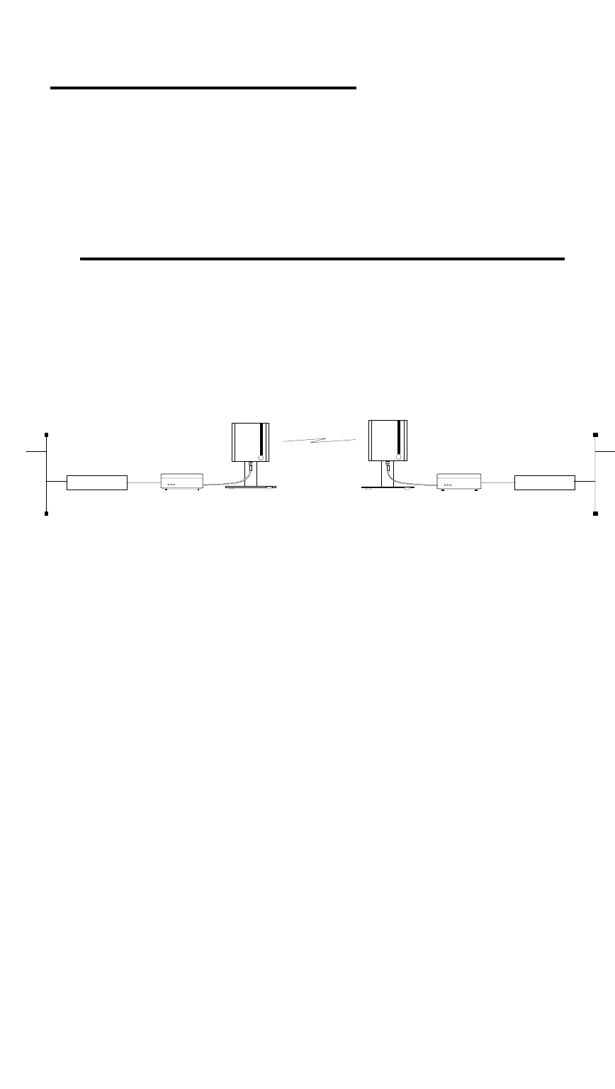
1.4.1 Point-to-Point connections with WIMAN LINE
WIMAN LINE radio modems enable point-to-point connections
between local area networks, data terminals or individual per-
sonal computers. In general, the WIMAN LINE can replace a
wire communication or a zero-modem cable. At present the
WIMAN LINE supports duplex data transmission rates of 256
kBit/s at 2FSK
WIMAN Line
Router WIMAN Line Router
Figure 1 Point-to-Point connection using WIMAN LINE
2 The WIMAN Command Line Level
11 / 90l
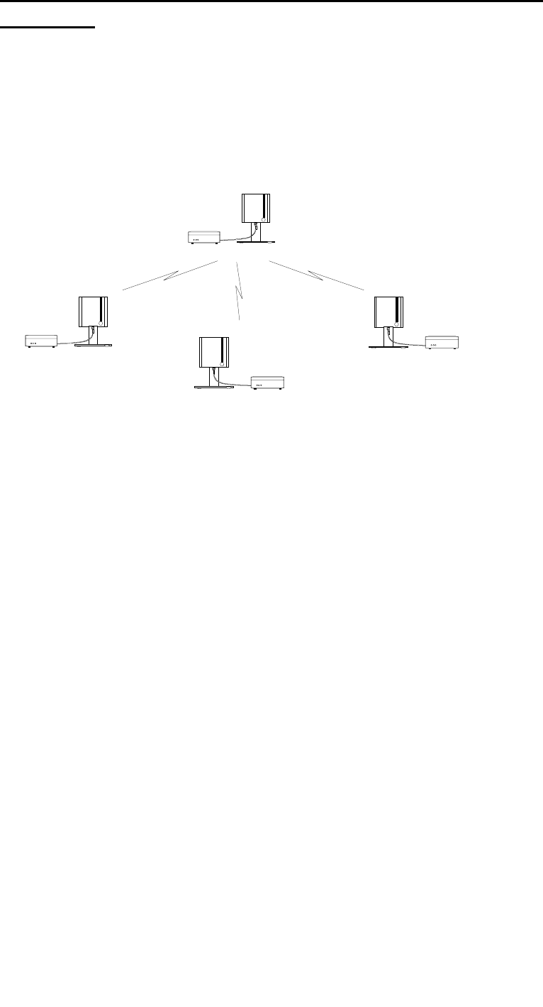
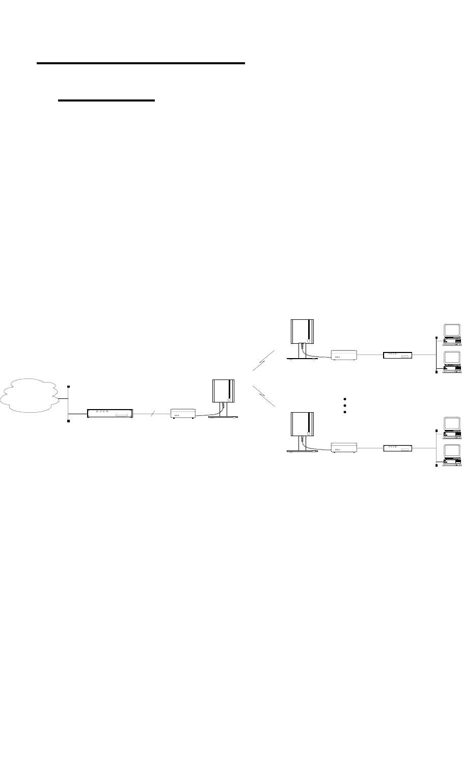
1.4.2 Cellular Networks using WIMAN STAR and WIMAN
ACCESS
One of the outstanding features of the WIMAN series is its abil-
ity to support point-to-multi-point networks with technically ma-
tured distribution of load between the individual ACCESS de-
vices (load balancing).
Figure 2 shows a typical network environment.
WIMAN
Access
WIMAN
Star
WIMAN
Access
WIMAN
Access
Figure 2 wireless access networks with WIMAN STAR
and WIMAN ACCESS
This network configuration can be used as a wireless connection
to the Internet.
The current software-Version supports up to 9 WIMAN
ACCESS per WIMAN STAR. They can be configured to meet
higher density of traffic in the networks by use of several syn-
chronized parallel WIMAN radio modems.
Avoid errors by synchronization of the WIMAN units (see chap-
ter 4.5 on page 53).
2 The WIMAN Command Line Level
12 / 90
1.5 Transmission Protocols
1.5.1 Frame Relay
The WIMAN system supports the Frame Relay protocol widely
used at many Telephony companies.
It operates smoothly in Frame Relay networks and enables the
application of commercial Frame Relay compatible Router as
switches on the STAR- and the ACCESS side.
Except for the supply of an Internet access, it is additionally
possible to use the WIMAN Frame Relay system for telephony
uses. Therefore, commercial Frame Relay multiplexers from
companies such as RAD, NUERA, CISCO, etc. can be used.
The Frame Relay support is a software-configurable feature and
is starting from the software-Version T.05. This software ver-
sion does also support leased line functionality.
Frame Relay
Router / Switch
Network
WIMAN
Access 1
WIMAN
Star
WIMAN
Access n
Frame Relay
Access Device
Frame Relay
Access Device
X.21
512 kbps
Figure 3 Standard Frame Relay applications
Router *: Any Frame Relay-Router or Switch with Synchronous
X.21-port (128 kBit/s), RFC 1490-Standard
- LMI has to be switched off, DLCI is configured statically.
Router **: Any Frame Relay-Router or Switch with synchro-
nous X.21-port (128 kBit/s), RFC 1490-Standard
- LMI has to be switched off, DLCI is configured statically.

2 The WIMAN Command Line Level
13 / 90l
2 The WIMAN Command Line Level
The operating system of the WIMAN radio modem has an inte-
grated command line interpreter ("Shell") for configuration of
the WIMAN. Input and output is visible on the input or output-
window of a PC terminal program (e.g. TELIX, ZOC).
So that communication between the terminal program and the
WIMAN can take place, the communication parameters of the
terminal program and the WIMAN must correspond.
The configuration of the WIMAN radio modem is executed with
instructions on the command line level (“Shell”). There is no
distinction between upper- and lower case characters (except for
passwords).
The command line level can be accessed via different interfaces.
Successful locking on the command line level is acknowledged
by display of the command line prompt. The factory setting of
the command line prompt is WIMAN II >.
The user may personalize the command line prompt (e.g.
DEVICE 1:).
2.1 Authorization Levels
The command line level has two different authorization levels
that differ in the number of changeable parameters. Therefore,
the WIMAN radio modem may be configured by diversely
qualified and permitted persons (e.g. user, Provider).
The last character of the command line prompt displays the au-
thorization level you are in at that time.
The authorization levels are represented as follows:
• Authorization level 1 WIMAN II >
• Authorization level 2 WIMAN II #
Each authorization level can be protected with a different pass-
word. However, a password for authorization level 2 is always
needed.
2 The WIMAN Command Line Level
14 / 90
2.2 Passwords
Passwords serve to protect the WIMAN from unauthorized ac-
cess to the command line level in the different authorization lev-
els. All passwords must have a length from four to eight charac-
ters. For the passwords the following characters may be used:
" a... z ", " A... z ", " 0... 9 ", " - ", " @ ", "?", " \ ", " [ ", " ] ", "
< ", " > ".
NOTE:
The WIMAN DOES acknowledge case sensitivity characters for
passwords.
Attention
Typing in of any other characters than the ones mentioned above
may lead to a reset of the WIMAN shell.
If no password is assigned for the authorization level one, the
command line appears when the WIMAN is switched on. Oth-
erwise you are asked to enter a password to access the command
line level one.
A password for authorization level two is always required. This
password cannot be deleted, however it is possible to modify
this password.
In case of a false configuration or a forgotten password in the
lowest authorization level (e.g. user authorization level) quali-
fied personnel are needed to access the unit (e.g. Provider). It is
possible to gain access directly to level two by entering the des-
ignated password for that level.
With suitable instruction (see chapter 3.5.1, on page 40) you can
reset the password for authorization level one.
If, for any reason, you are unable to arrive at the necessary au-
thorization level any longer and you are thus closed out of the
device, it is possible to gain access with a master password. The
master password can only be used after the third unsuccessful
access attempt and can only be made via the serial interface.
Further information on this issue can be obtained from your
WIMAN Distributor.
Attention:
The input of the master password can be executed exclusively
over the RS-232 port and results in resetting of all parameters to
their factory settings. A reconfiguration of the device will be
necessary afterwards.

2 The WIMAN Command Line Level
15 / 90l
2.3 Operation Modes
On the command line level, the following operating modes are
differentiated with respect to each authorization level:
• Command mode and
• Configuration mode.
In command mode you can view the accepted parameters of the
present configuration (current config) as well as give the ac-
cepted commands for this mode and authorization level (see
Chapter 2.6.1 on page 25).
In configuration mode you may change only the parameters al-
lowed for that specific authorization level.
The system software indicates these parameters as “new con-
figuration” (new config). You may render certified instructions
for this level and this mode.
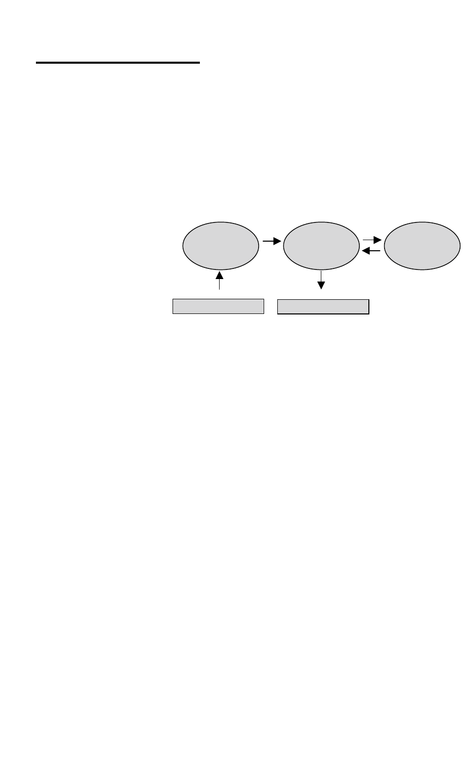
Figure 4 shows how to switch between the different authoriza-
tion levels and operation modes.
pw password
[] optional
(n) Authorization level
en enable
Figure 4 Diagram of the different operating modes
serial connection /
Telnet
Reset pw ← ↓ [pw] ↑ exit ↑ exit
↓
Reset Config ←
pw
→
Command Mode
(1) →
en pw
Command Mode
(2)
↓ config ↑ exit ↓ config ↑ exit
Config Mode Config Mode
2 The WIMAN Command Line Level
16 / 90
2.4 Configuration Data
The configuration data (values of the adjustable parameters) is
classified into the following three types:
• New configuration (new config),
• Present configuration (current config) and
• Non-volatile configuration (boot config).
Figure 5 shows the connections of the three different types of
configuration data.
The new configuration is created by modification of the pa-
rameters in the configuration mode (see Chapter 2). This has no
effect on the current operation. It is possible to produce a new
configuration by manually changing the parameters or by read-
ing-in a parameter text file. In the parameter text file comments
may be inserted at the start of a line or after an instruction (See
Chapter xxx on page xxx).
The present configuration consists of the parameters used by
the system at that time. This configuration can be saved as a text
file.
The non-volatile configuration consists of the parameters
called on and made the present configuration at a strat or restart
of the device. Modified parameters (new configuration) can ei-
ther be taken over (transfer for present configuration) or rejected
by a query when leaving the configuration mode.
The up-to-date parameters (present configuration) can be per-
manently taken over by a further query when leaving the com-
mand mode (transfer into the non-volatile configuration) or
maintained only up to the next restart.
ASCII- command-file ASCII- configuration file
(new config)
(current config)
(boot config)
optional optional
optional
optional
necessary
Figure 5 Configuration data

2 The WIMAN Command Line Level
17 / 90l
2.5 Configuration Parameters
The WIMAN radio modems are delivered with a factory-
installed standard setup. To adjust the WIMAN to your specific
requirements you can modify different parameters (depending
on the authorization level).
The configurable Parameters are classified into the following
groups:
• Parameter for the wireless interface,
• Parameter for the serial interface,
• Parameter for the network,
• Other parameters.
All parameter can only be changed in the configuration mode of
the appropriate level.
2.5.1 Parameter for the Wireless Interface
The following parameters affect the wireless interface and serve
to set up the network configuration. These parametersalso set up
countermeasures against possible disturbances in the operating
frequency band.
The parameter destination determines the destination address of
the WIMAN, to which all data will be sent.
Note:
This setting is only available on WIMAN LINE units and is not
used on WIMAN STAR and ACCESS units.
Authorization Level: 2
Preset value: 1
Scope: 0 ... 250
The parameter FTab determines the frequency-hopping pattern
between the 80 channels. Each WIMAN radio-modem comes
with a factory installed frequency-hopping pattern that cannot be
changed. However, it is possible to create a second frequency-
hopping pattern to be used in place of the standard one. In this
case the new pattern can be set with FTab.
Authorization Level: 2
Destination
FTab

2 The WIMAN Command Line Level
18 / 90
The user-defined hopping pattern must be switched on with
FtabMode set to USER.
Authorization Level: 2
Preset value: System
Scope: System, User
The parameter LoopData sets the hexadecimal value to be sent
in a LoopTest.
Authorization Level: 2
Preset value: FFFFFFFF
Scope: 00000000 … FFFFFFFF
The parameter LoopMode determines, which bit pattern and
frame lengths are to be used with the independent back loop test
(see loop test below). This parameter is not available on STAR
devices.
It is possible to set the values normal, load, long and high. The
values function as follows:
• Normal
Pseudo coincidental data is transmitted. All 256 byte values
occur equivalently. A break is inserted between two pack-
ages. This type of test is to simulate the "normal" data
communication in a network.
• Load
Pseudo coincidental data is transmitted. However, in this
type of test it is transmitted with highest possible transfer
rate.
• Long
“Stress” data (bit pattern, which lead to a high utilization) is
transmitted at a normal transfer rate.
• High
“Stress” data is transmitted with high transfer rate.
Attention:
If the looptest is executed in an operating radio net, all values
except normal should be avoided for the parameter LoopMode.
Use of any other value may result in malfunction.
Authorization Level: 2
Preset value: long
Scope: normal, load, long, high
LoopMode
FTabMode
LoopData

2 The WIMAN Command Line Level
19 / 90l
The parameter LoopTest yields a back loop test. If loop test is
set to True, the WIMAN begins to transmit test data in back
loop operation. Therefore, it is possible to check procedure sta-
tistics during the test. This parameter is not available on STAR
devices.
Authorization Level: 2
Preset value: False
Scope: True, False
The parameter MaxRetry determines the maximum number of a
repeated package dispatching. A package is dispatched again
only in the case of a failed checksum test. If a package fails the
checksum test, the WIMAN tries to send the package again. The
number of attempts to resend the package can be determined in
MaxRetry.
Authorization Level: 2
Preset Value: 9
Scope: 0 ... 9
The parameter NetId determines the network address of the
WIMAN. The WIMAN analyses only the data communication
that is addressed to the network address configured on it. NetID
also determines which frequency-hopping table is used.
Attention:
Please note that if several WIMAN networks are situated in
close geographical location identical NetIds may not be used.
Authorization Level: 2
Preset value: 255
Scope: 0 ... 255
The parameter NodeId determines the non-standard address of a
WIMAN radio modem within a network. A NodeID with the
value 0 automatically changes the WIMAN radio modem to
MASTER operation. NodeIDs of 1... 250 automatically switch
a WIMAN radio modem into the SLAVE operation with appro-
priate NodeIDs from 1... 250. Two WIMAN radio modems in
the same network (same NetId) may not possess identical
NodeIDs. Disturbance would occur and communication would
be lost until one of the devices is switched off.
This effect does not occur, if a serial number for this NodeID is
set with the instruction peer (see peer below). In this configura-
tion, the WIMAN radio modem with the adjusted serial number
NetId
NodeID
LoopTest
MaxRetr
y

2 The WIMAN Command Line Level
20 / 90
would function perfectly and all other devices with the same
NetId and NodeId would be ignored.
Authorization Level: 1
Preset value: 0 (WIMAN Star)
Scope: 0 ... 250
The parameter RadioPower activates the normal operation or
switches into a low power mode (around 0 dBm, regardless of
the Region or Antenna setting). When there is only a small dis-
tance between a STAR and ACCESS the transmitting power can
be scaled down to avoid overriding of the input-stage.
Authorization Level: 2
Preset value: Normal
Scope: Normal, Low
The parameter Antenna specifies the type of antenna used with
the WIMAN and thus determines the specific settings (e.g.
transmit power) required for that type of antenna.
Authorization Level: 2
Preset value: 8mn360
Scope: 2mn360, 8mn360, 85pl76, 16pl27,
24pf20
In addition to the parameter Antenna, the parameter Region sets
the WIMAN radio to the specific settings required in that spe-
cific region (output power, frequency-range, etc.).
Authorization Level: 2
Preset value: depending on region
Scope: 1 valid for ETSI-compliant
operation
2 valid for FCC-compliant
operation
Note:
Incorret setting of the parameters 'Antenna' and 'Region' may
lead to non-permitted behaviour of the unit and will void the
right of operation !
If you are not sure which operation mode the WIMAN unit must
comply with, please refer to your local distributor or manufac-
turer of this system.
RadioPower
Region
Antenna