WIMAN Systems WIMAN2A24 FHSS RF Modem User Manual Introduction to WIMAN technology
WIMAN Systems Inc FHSS RF Modem Introduction to WIMAN technology
Contents
Manual7

71 / 90l
Appendix A: WIMAN Hardware
8.2 Antenna systems
Different antenna systems can be used with the WIMAN radio
modem:
Part.-No. 750081 750083 750001 750040 750061 750062
Matchcode AN-24-
2MN360-
FMEM
AN-24-
8MN360-NF3 AN-24-
8PL76-SMAF AN-24-
16PL24-NF AN-24-
24PF8-NF AN-24-
16PL85-NF
Type Omni
directional
Omni direc-
tional, 3° down-
tilt planar planar paraflector Planar
Gain [dBi] 2 8 8,5 16 24 16.5
Azimuth
[degrees] 360 360 75 27 7 85
Elevation
[degrees] > 60 13 60 27 10 6
Height [cm] 12 43 11 28 61 127
Width [cm] 3 3 9 28 92 8
Depth [cm] 3 3 3 4 38 5
Weight [kg] 0.04 0.2 0.1 0.9 2.4 2.1
Front/Back Ra-
tio
[dB] N/a n/a 20 40 31 25
VSWR (max.) 2 1.5 1.5 1.5 1.3 1.5
Connector FME male N female SMA female N female N female N female
72 / 90
Appendix A: WIMAN Hardware
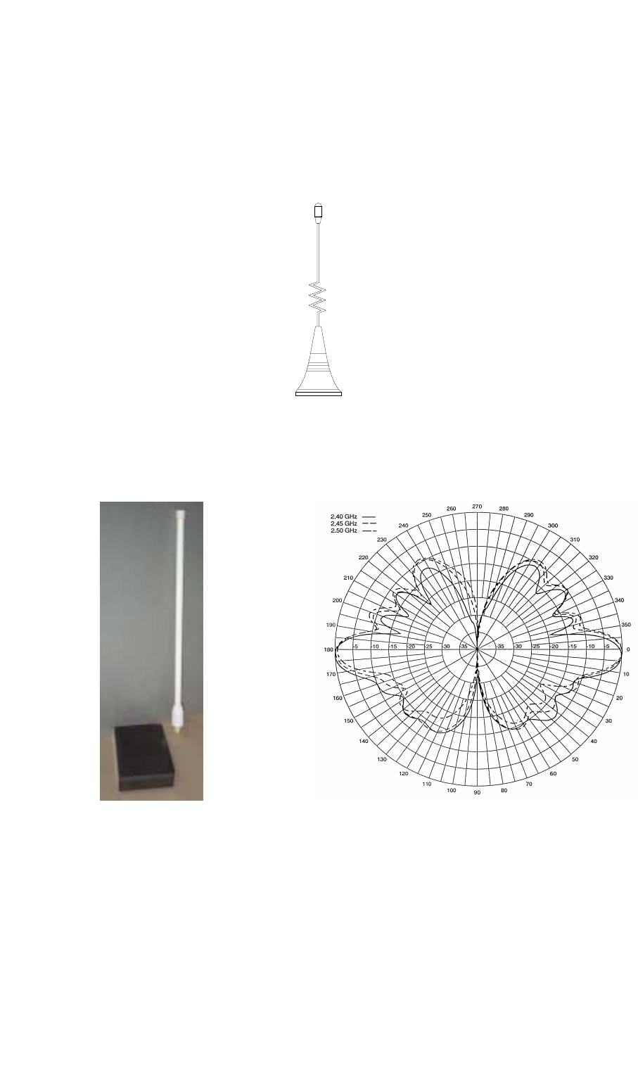
• Omni directional antennas
Typically these antennas are used with WIMAN STAR sta-
tions.
AN-24-2MN360-FMEM
2 dBi
AN-24-8MN360-NF3
8 dBi, 3 deg downtilt
73 / 90l
Appendix A: WIMAN Hardware
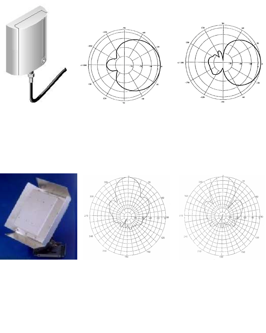
• Planar antennas
These antennas are mainly used at the customer side in
connection with the WIMAN ACCESS. They can be used
also for point-to-point connections with WIMAN LINE
units.
AN-24-8PL76-SMAF
8.5 dBi
Picture Azimuth Pattern Elevation Pattern
AN-24-16PL24-NF
16 dBi
Picture Azimuth Pattern Elevation Pattern
74 / 90
Appendix A: WIMAN Hardware
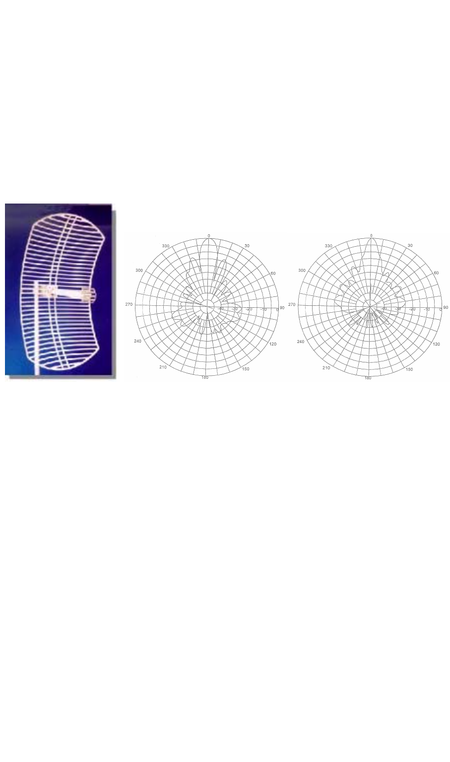
• Paraflector antennas
These antennas were developed mainly for point-to-point
connections over long distances.
AN-24-24PF8-NF
24 dBi
Picture Azimuth Pattern Elevation Pattern
75 / 90l
Appendix A: WIMAN Hardware
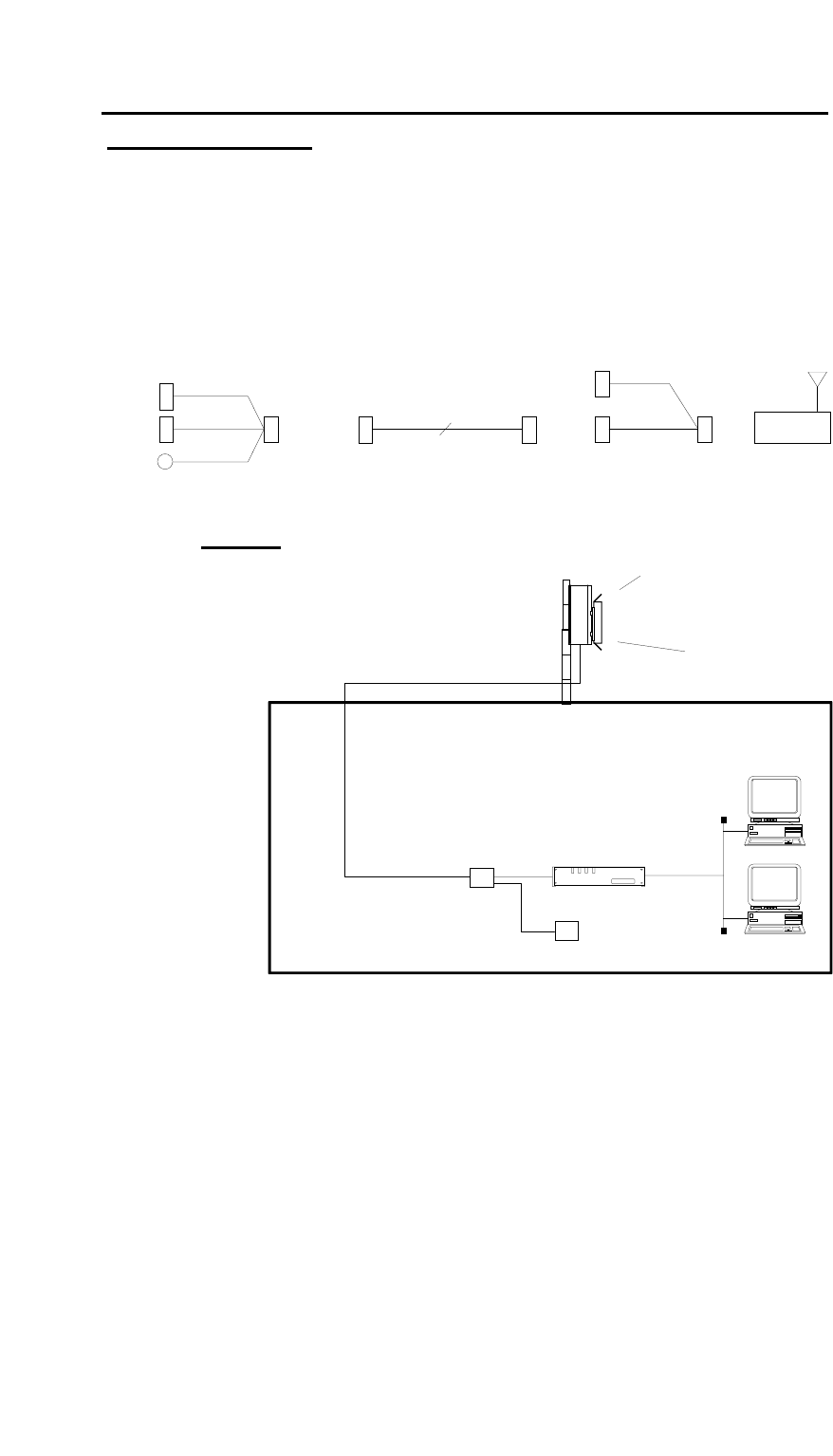
8.3 Hybrid-cable sets
Nachfolgend sind einige Anschlussbeispiele für die verschiede-
nen Hybridkabel aufgeführt. Eine genaue Beschreibung der ein-
zelnen Hybridkabel ist in Kapitel 8.4 auf Seite 78 nachzulesen.
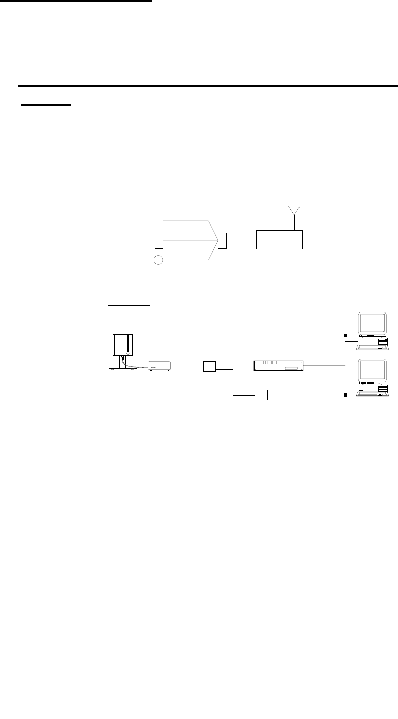
8.3.1 Standard Connection (Indoor) using Hybrid cable
Type 1
Hybrid-cable Type 1 is only used when a WIMAN is directly
connected to a Router (e.g. CISCO). This type of connection can
be used for devices, which are in close range to the Router (In-
door-Installation).
SubD 37 F
SubD 15 F
SubD 9 F
DIN M
(H1-X21C-37)
X.21
Config
24 V
WIMAN
Sample:
Frame Relay
Access Device
Power supply
Hybrid-
cable
WIMAN Access
(incl. Planar-
antenna) LAN
76 / 90
Appendix A: WIMAN Hardware
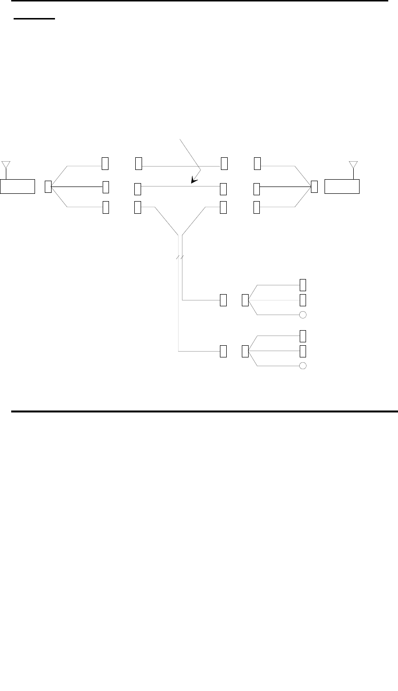
8.3.2 Outdoor Installation using Hybrid cable Type 2 & 3
and Datacable
This connection is used when the WIMAN is installed on a roof-
top or a radio tower and is synchronized among other WIMAN
devices. In addition a data cable (12x2) is needed.
SubD 25 M SubD 37 F
SMA F
SubD 25 F
(H2-X21C-25)
12 x 2
(H3-X21C-37)
SubD 15 F
SubD 9 F
DIN M
X.21
Config
24 V SubD 25 F SubD 25 M
Syncronization
Datacable
(max. 100m) WIMAN
Sample:
WIMAN Access
Outdoor-Set
(incl. Planar-Antenna
and Hybrid-Cable)
Frame Relay
Access Device
Power Supply
Hybrid-
Cable
LAN
Datacable
(max. 100m )
77 / 90l
Appendix A: WIMAN Hardware
8.3.3 Connection of a remote POP with WIMAN LINE and
STAR
This link is used for a remote Point Of Presence, if a WIMAN
STAR is connected via a WIMAN LINE link. Here the STAR
receives the synchronisation impulses likewise via the LINE
link.
SubD 37 F
SMA F
V.24 +
24 V
Syncronization
RG 316
X.21 Zeromodem
S 25 F
V.24 + 24 V
12 x 2
SMA M
SubD 25 F
SMA M
SubD 15 F
SMA F
SubD 15 M
SubD 25 M
V.24 +
24 V
X.21
Syncronization
Hybrid Cable Type 4
(H4-X21C-37)
Zeromodem X.21
(NULL-X21C-15)
SubD 15 F
(not connectible)
SubD 9 F
DIN M
Hybrid Cable Type 2
(H2-X21C-25)
S 25 F
S 25 M
S 25 M
Config
24 V
SubD 9 F
DIN M
Config
24 V
(H4-X21C-37)
SubD 15 F
(not connectible)
SubD 25 M
WIMANWIMAN
SubD 15 M
SubD 25 F
SubD 15 F
Extension cable
(max. 100m)
SubD 37 F V.24 +
24 V
X.21
Syncronization
8.3.4 Connections when using the IP-routing functionality
Still being revised
78 / 90
Appendix A: WIMAN Hardware
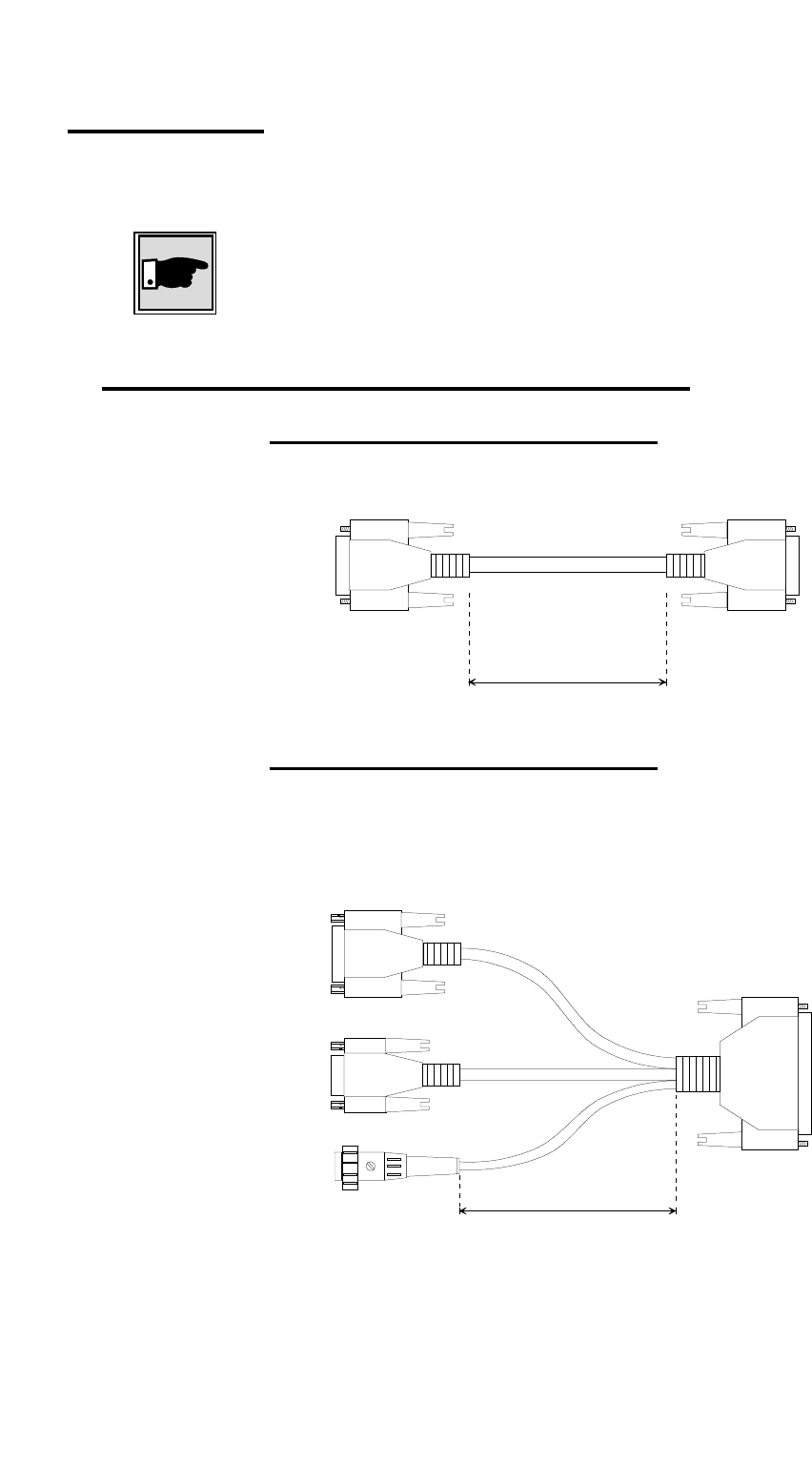
8.4 Hybridcable
In the following, all hybrid cables with their appropriate area of
application are described.
Note:
The 37-pin SubD link (female) is always attached to the 37-pin
SubD link (male) of the WIMAN.
8.4.1 Hybridcable used for X21-configurations
Zeromodemcable (NULL-C21-15)
Zeromodemcable for direct connection of 2 WIMAN devices. In
addition a Hybrid cable Type H4 is needed.
female
14 x 0,15 mm², shielded,
UV-resistant
1000 mm
S 15 S 15 female
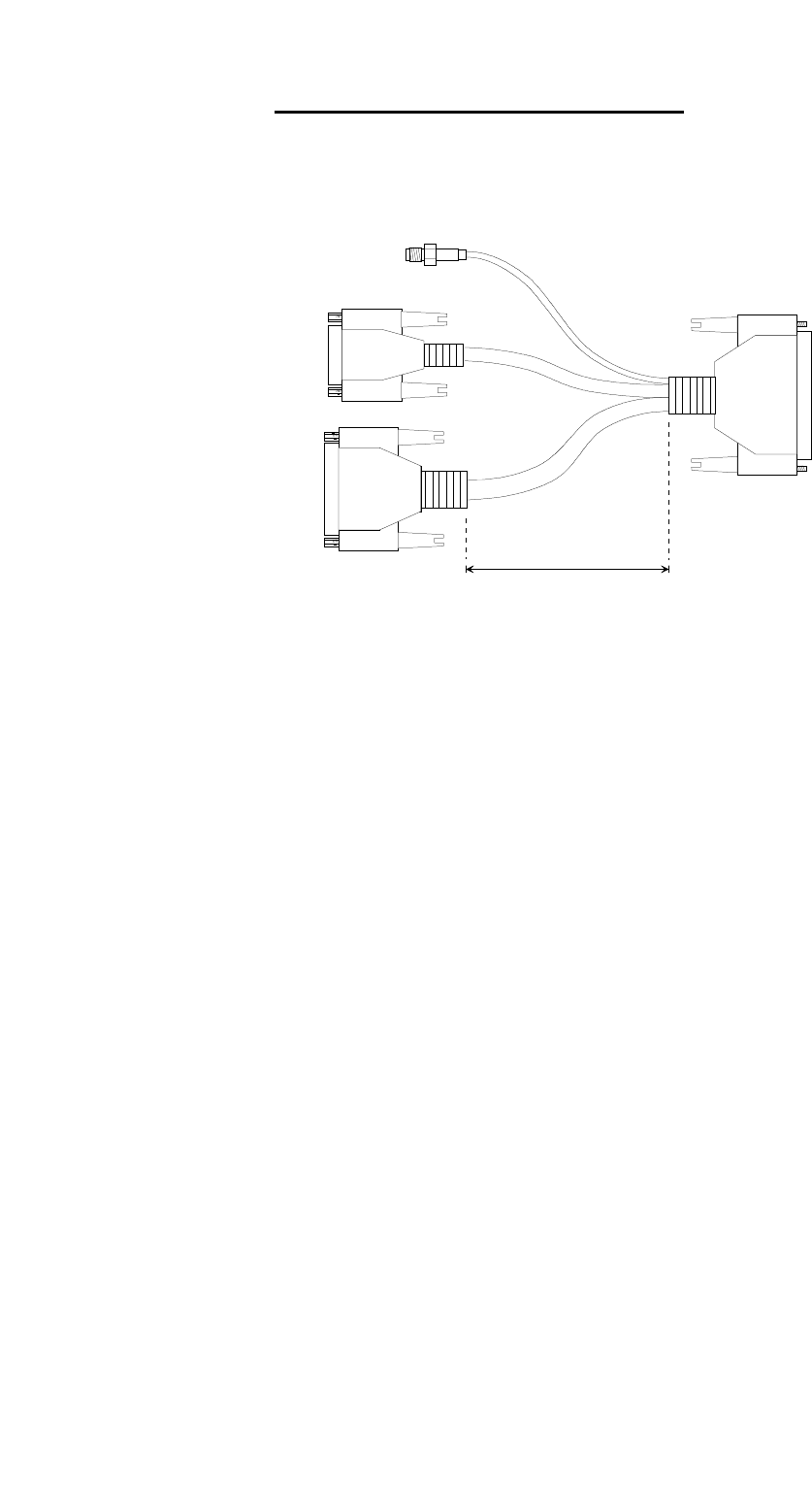
Hybridcable Type1 (H1-X21C-37)
This hybrid cable is used with indoor installations and provides
the power connection, a direct link for a Frame Relay capable
Router as well as a configuration interface (RS-232).
S 37
male
female
11 x 0,15 mm², shielded
3 x 0,15 mm², shielded
5 x 0,15 mm²
female
with nut
300 mm
S 15
DIN Renk,
3
p
in
S 9
female
with nut
79 / 90l
Appendix A: WIMAN Hardware
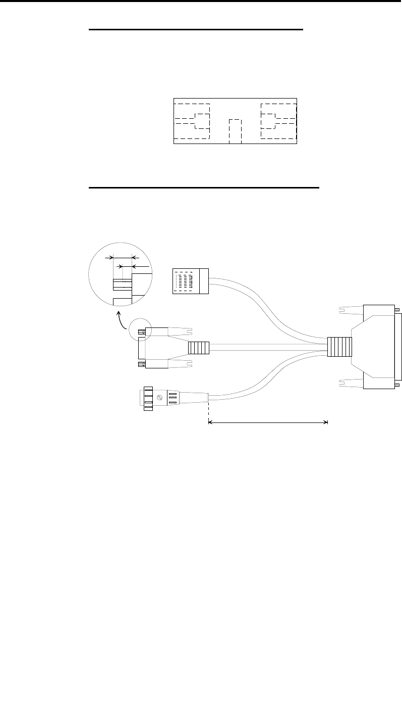
Hybridcable Type 2 (H2-X21C-25)
This Hybrid cable is being used as an internal termination cable
when installing a WIMAN on a readio-tower on on a rooftop.
The 25pin SubD-plug (male) is connected to the 12x2 Data-
cable, which leads from the WIMAN to the Router. All other
connectors are the same as on Hybrid cable type 1.
SubD 25
male
S 25
11 x 0,15 mm², shielded
5 x 0,15 mm²
3 x 0,15 mm², shielded
SubD 15
female
with nuts
300 mm
S 15
S 9
SubD 9
female
with nuts
DIN Renk, 3 pin,
180 de
g
rees
,
male
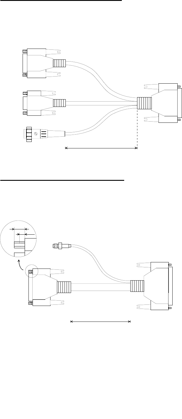
Hybrid cable Type 3 (H3-X21C-37)
This hybrid cable is attached with outdoor installations between
the WIMAN and the data cable (12x2). The SMA socket serves
for the link to the synchronisation bus, if several WIMAN de-
vices are mounted in direct proximity.
S 37
SubD 37
female
SMA
female
SubD 25
male
with nuts
RG 316
23 x 0,15 mm², shielded, paired
400 mm
S 25
Date: 27. June 2000
2 mm
6 mm
80 / 90
Appendix A: WIMAN Hardware
Hybrid cable Type 4 (H4-X21C-37)
This hybrid cable is used with a Peer to Peer structure of a re-
mote POP. For this an additional NULL-X21C-15 cable, a syn-
chronisation bus, a data cable (12x2) and a hybrid cable Typ2
becomes necessary (schematic structure see further above.)
S 37
female SMA
male
with nut
female
9 x 0,15 mm², shielded
13 x 0,15 mm²,
shielded
RG 316
400 mm
S 15
S 25
male
with nut
81 / 90l
Appendix A: WIMAN Hardware
8.4.2 Hybrid cable when using the IP-routing-functionality
RJ45-Connectionbox (HA-ETH-45)
This link box is attached between the Ethernet cable of the local
network and the hybrid cable H3-eth-37ext. Into the box the cur-
rent supply link of the WIMAN, which is connected to the
power pack, is integrated.
RJ 45
female RJ 45
female
Hybrid cable Ethernet 1 (H1-ETH-37)
This Ethernet hybrid cable is used for indoor installations and
provides the power connection, a direct link to the local network
(over Ethernet cable) and a configuration interface (RS-232).
SubD 37
female
4 x 0,15 mm², shielded, paired
3 x 0,15 mm², shielded
5 x 0,15 mm²
300 mm
DIN Renk, 3 pin,
180 de
g
rees
,
male Date: 10. July 2000
SubD 9
female
with nuts
RJ45,
female
2 mm
6 mm
82 / 90
Appendix A: WIMAN Hardware
Hybrid cable Ethernet 2 (H2-ETH-25)
This hybrid cable is used as internal terminal cable with radio
tower installations or installation of the WIMAN on a rooftop.
The 25-pin SubD (male) link is connected to the data cable
(12x2), which leads from the WIMAN (outdoor) to the inward.
The further interfaces correspond to those of the hybrid cable
Type Ethernet 1.
SubD 25
male
S 25
4 x 0,15 mm², shielded, paired
5 x 0,15 mm²
3 x 0,15 mm², shielded
300 mm
S 9
SubD 9
female
with nuts
RJ45,
female
DIN Renk, 3 pin,
180 de
g
rees
,
male
2 mm
6 mm
Date: 10. July 2000
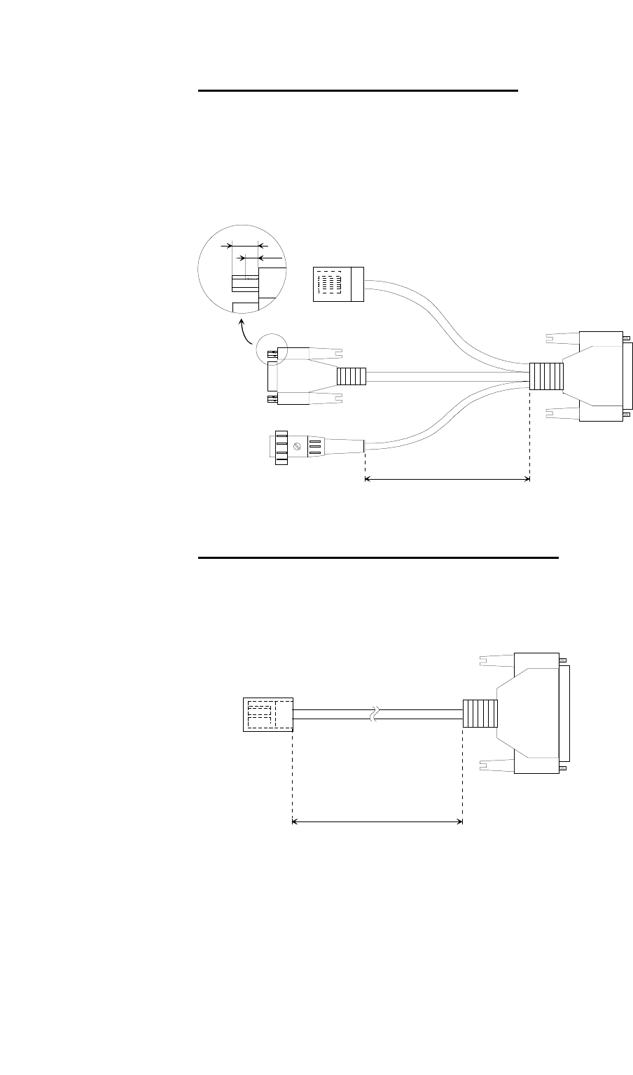
Hybrid cable Ethernet 3 (H3-ETH-37EXT)
This hybrid cable serves for the link of the WIMAN to the local
Ethernet. The current supply lines of the WIMAN are already
integrated in this cable. This cable can be used only together
with the link port HA-ETH-45.
S 37 SubD 37
female
25 m
RJ45 male
incl. protective cap
Cat 5, STP

83 / 90l
Appendix B: Technical data
9 Appendix B: Technical data
Product outline
WIMAN Star, Access high-speed transfer in point-to-
multi-point mode
WIMAN Line flexible point-to-point transfer
Radio
Frequency range 2.400 - 2.4835 GHz
Type of modulation Spread Spectrum Frequency
Hopping 2-FSK, 4-FSK
Number of channels 80, non-overlapping
Wireless interface 1 Mbps, 2-FSK
2 Mbps, 4-FSK
Transmitting power 100 mW (ETSI-Version) (E.I.R.P.)
4 W (FCC-Version) (E.I.R.P.)
(650 mW max output-power @
RF-connector)
Transfer capacity 256 KBps @ 2-FSK
512 KBps @ 4-FSK
Max. input-level 0 dBm
Recipient- -94 dBm @ 2-FSK
sensitivity -88 dBm @ 4-FSK
Range up to 5 km (ETSI-Version with pla-
nar array antennas)
up to 25 mi (FCC-Version)
RF-connector SMA plug connector
RF interface
Configurable block-repetition
CRC-based error correction
In-slot acknowledgement
Device-specific data encryption
Data-interface
Synchronous X.21 / V.35 (optional) max. 2 Mbps

84 / 90
Appendix B: Technical data
Protocols
Point-to-point-mode
Synchronous Transparent (HDLC-
frame structure)
Point-to-Multipoint-mode
Synchronous operation Frame Relay Packet Switching
Antennas
Mobile antenna Omnidirectional 2 dBi
Fixed antennas Omnidirectional 8 dBi
Planar 8.5 dBi
Planar 16 dBi
Paraflector 24 dBi
Mass & weights (without antennas)
WIMAN-device 176 x 110 x 40 mm, 1050 g
Outdoor box 300 x 190 x 85 mm, 2200 g
General
Voltage supply 12 – 26 V =; max. 10 W
110 – 230 V, 50 -60 Hz~
Temperature range -20°C - +55°C
Humidity 100 %, not condensing
IP enclosure IP63, mounted in security housing
Display 3 LEDs, two-colored
Administration
Remote looptest
SNMP-based status-query and error signaling
Network access via TCP / IP, password protected
Software-update via TFTP
Individual bandwidth management

Appendix C: Pin-allocation of the Datacables
85 / 90l
10 Appendix C: Pin-allocation of the Data-
cables
10.1 WIMAN Datacable (10 x 2)
Pin Wire color (1. line) Pin Wire color (2. line)
1 White/Grey 14 White/Green
2 - 15 Brown/Green
3 White/Yellow 16 Pink/Brown
4 Yellow/Brown 17 White/Pink
5 White 18 Grey/Pink
6 Brown 19 Red/Blue
7 - 20 -
8 Grey/Brown 21 Black
9 Green 22 Purple
10 Yellow 23 -
11 Pink 24 Red
12 Grey 25 Blue
13
Table 7 WIMAN data cable (10 x 2), pin assortment
Attention:
Provide a correct grounding of the data cable screen.
Paired-wire Wire color Pin number Wire color Pin number
1 White 5 Brown 6
2 Green 9 Yellow 10
3 Grey 12 Pink 11
4 Blue 25 Red 24
5 Black 21 Purple 22
6 Grey/Pink 18 Red/Blue 19
7 White/Green 14 Brown/Green 15
8 White/Yellow 3 Yellow/Brown 4
9 White/Grey 1 Grey/Brown 8
10 White/Pink 17 Pink/Brown 16
Shield Shield
Table 8 WIMAN data cable (10 x 2) paired-wire assort-
ment

Appendix C: Pin-allocation of the Datacables
86 / 90
10.2 WIMAN Datacable (12 x 2)
Pin Wire color (1. line) Pin Wire color (2. line)
1 White/Grey 14 White/Green
2 Grey/Brown 15 Brown/Green
3 White/Yellow 16 Pink/Brown
4 Yellow/Brown 17 White/Pink
5 White 18 Grey/Pink
6 Brown 19 Red/Blue
7 White/Blue 20 White/Red
8 Brown/Blue 21 Black
9 Green 22 Purple
10 Yellow 23 Brown/Red
11 Pink 24 Red
12 Grey 25 Blue
13
Table 9 WIMAN data cable (12 x 2) pin assortment
Attention:
Provide a correct grounding of the data cable screen.
Paired-wire Wire color Pin number Wire color Pin number
1 White 5 Brown 6
2 Green 9 Yellow 10
3 Grey 12 Pink 11
4 Blue 25 Red 24
5 Black 21 Purple 22
6 Grey/Pink 18 Red/Blue 19
7 White/Green 14 Brown/Green 15
8 White/Yellow 3 Yellow/Brown 4
9 White/Grey 1 Grey/Brown 8
10 White/Pink 17 Pink/Brown 16
11 White/Blue Brown/Blue
12 White/Red Brown/Red
Screen Screen
Table 10 WIMAN data cable (12 x 2) Paired-wire assort-
ment

87 / 90l
Fehler! Verweisquelle konnte nicht gefunden werden.
Appendix D: Alphabetical list of instructions
11 Appendix D: Alphabetical list of instruc-
tions
Instruction Applicable in command
mode starting from au-
thorization level
Applicable in configura-
tion mode starting from
authorization level
Remarks
<parname> <value> - 1
Checkcfg - 1
Clear 1 1
Clear stat <type> 1 -
Config 1 -
Del config - 1
Del <parname> - 1
Del passwd console - 1
Enable 1 - No help available
Exit 1 - No help available
Export 1 1
Help 1 -
Help <parname> 1 1
Passwd console - 1
Passwd console crypt - 1 No help available
Passwd enable - 1
Passwd enable crypt - 2 No help available
Reset 1 -
Reset config - 1 (configuration password) No help available
Restore - 1
Save 1 -
Show 1 1
Show <regexp> 1 1
Stat <type> 1 1
Swupdate 1
Table 11 alphabetical list of instructions

88 / 90
12 Index
12 Index
Will be created later

89 / 90l
13 Index of figures
13 Index of figures
Figure 1 Point-to-Point connection using WIMAN LINE.........................................10
Figure 2 wireless access networks with WIMAN STAR and WIMAN ACCESS.....11
Figure 3 Standard Frame Relay applications.........................................................12
Figure 4 Diagram of the different operating modes ...............................................15
Figure 6 exported configuration file .......................................................................28
Figure 7 Help display output..................................................................................30
Figure 8 the statistics assistance display...............................................................31
Figure 9 arrangement of equipment for the configuration of the WIMAN radio
modem.............................................................................................34
Figure 10 Frame Relay connections with the WIMAN ..........................................58
Figure 11 Simple WIMAN Network with CISCO-Router........................................62
Figure 12 front side of the WIMAN radio modem..................................................70
Figure 13 rear side of the WIMAN radio modem ..................................................70

90 / 90
14 Index of tables
14 Index of tables
Table 1 parameters of an extended point-to-point connection (connection 1) ..... 54
Table 2 parameter of an extended point-to-point connection (connection 2) ....... 54
Table 3 Structure of the 2 Byte long address array.............................................. 59
Table 4 NodeId with 2-Byte-Frame Relay address array ..................................... 60
Table 5 DLCI allocation in connection with 2-Byte-address array........................ 61
Table 6 bit sequence for different DLCI identifiers............................................... 61
Table 7 WIMAN data cable (10 x 2), pin assortment............................................ 85
Table 8 WIMAN data cable (10 x 2) paired-wire assort-ment .............................. 85
Table 9 WIMAN data cable (12 x 2) pin assortment............................................. 86
Table 10 WIMAN data cable (12 x 2) Paired-wire assortment ............................ 86
Table 11 alphabetical list of instructions ............................................................. 87