WIMAN Systems WIMAN2A24 FHSS RF Modem User Manual Introduction to WIMAN technology
WIMAN Systems Inc FHSS RF Modem Introduction to WIMAN technology
UserManual.wiki
>
WIMAN Systems
>
WIMAN2A24 User Manual
>
Manual7
Contents
1.
Manual01
2.
Manual02
3.
Manual03
4.
Manual6
5.
Manual7
6.
Manualpage2
Manual7
Navigation menu
Upload a User Manual
Namespaces
Wiki Guide
HTML
PDF
Info
Views
User Manual
Discussion / Help
Navigation
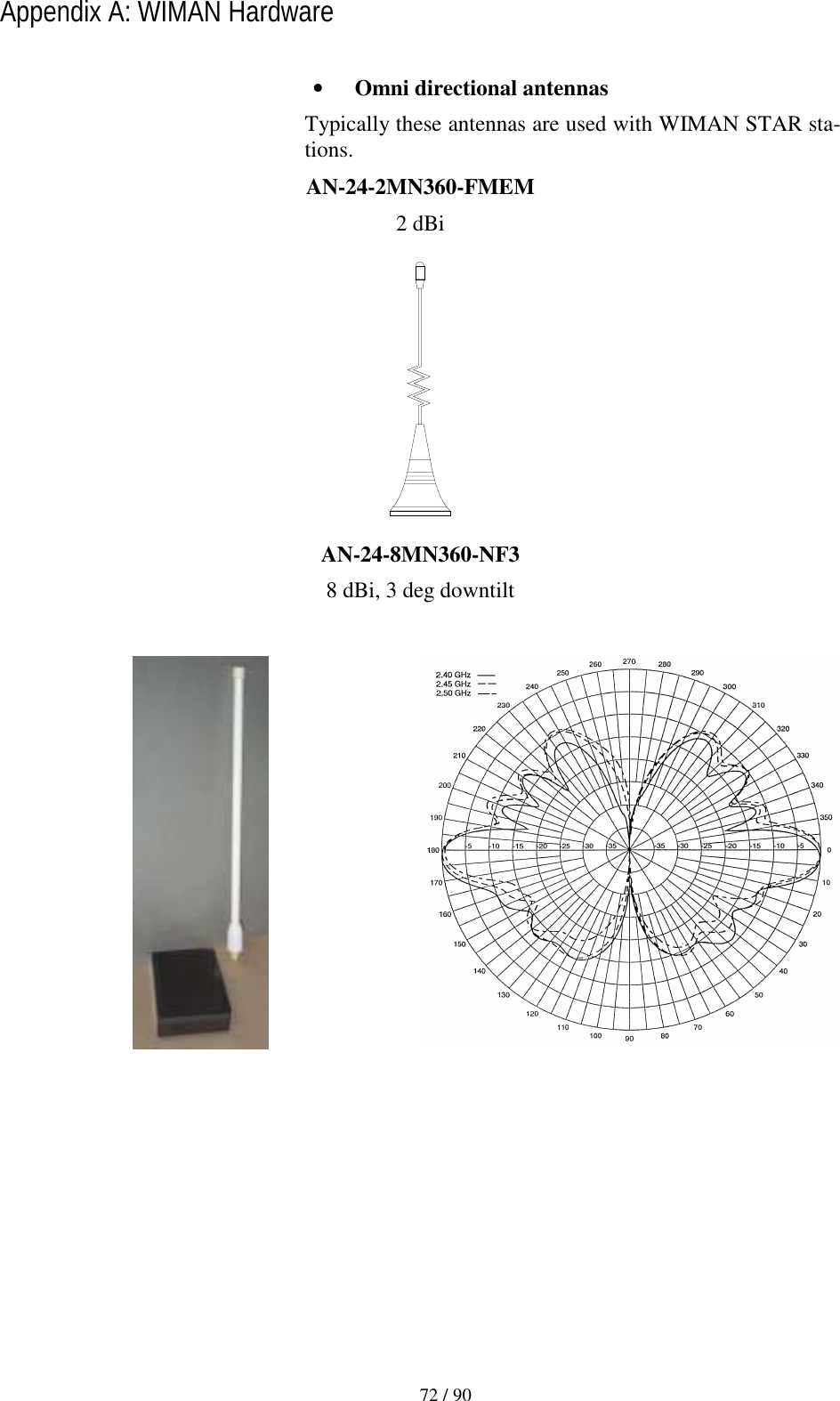
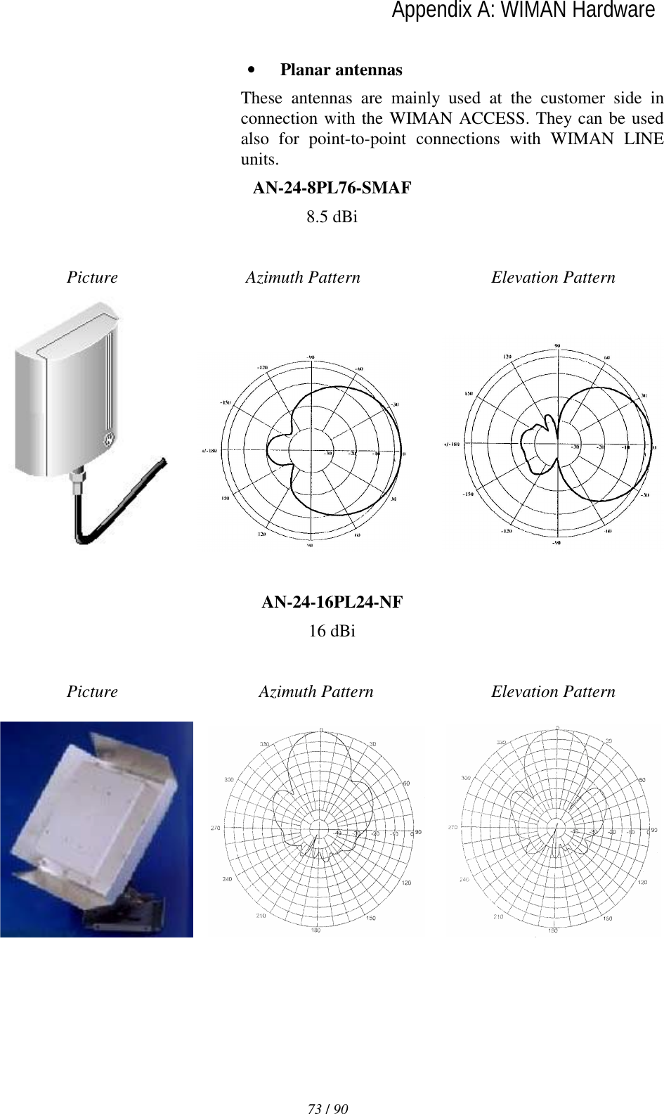
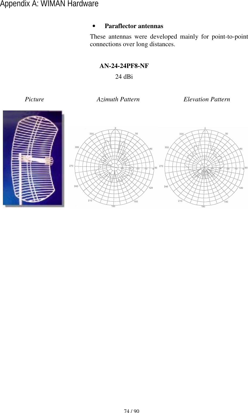
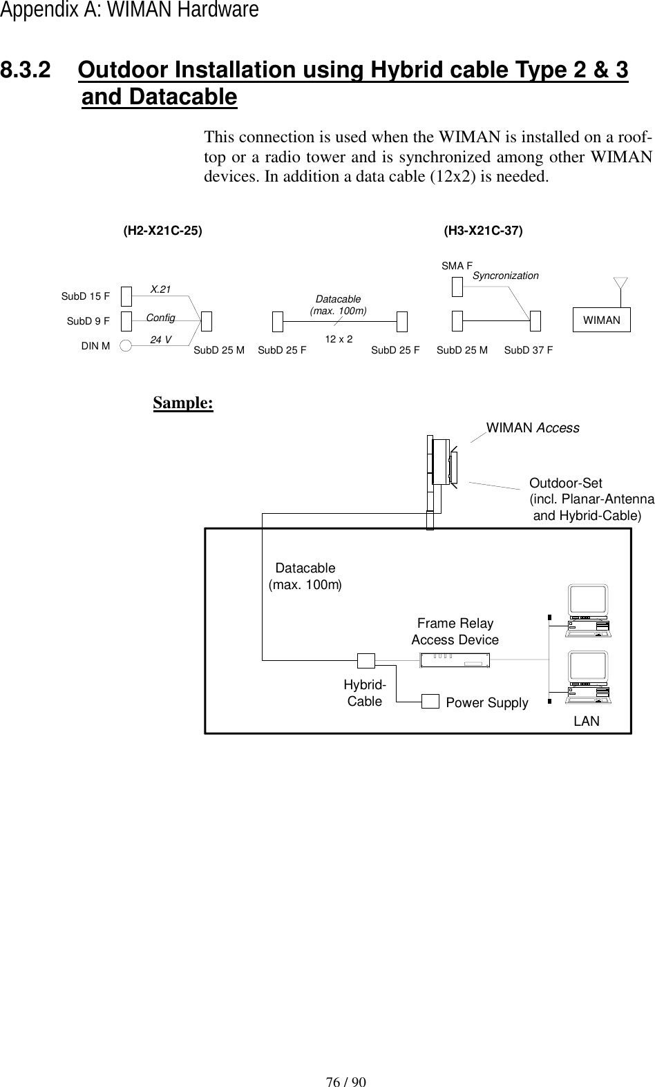
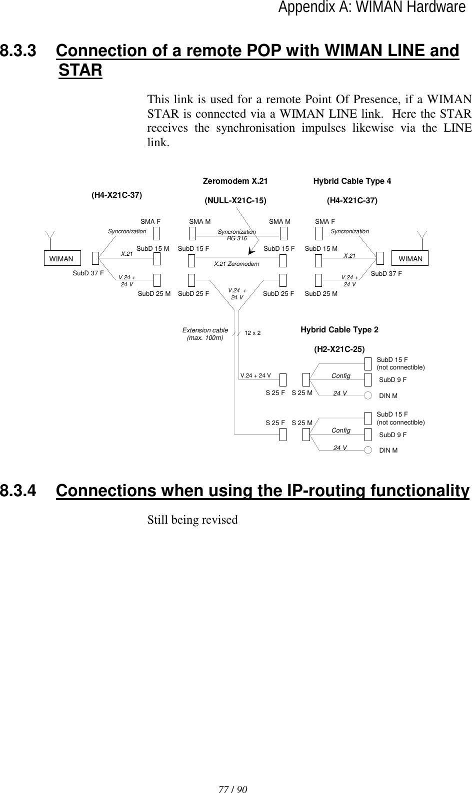
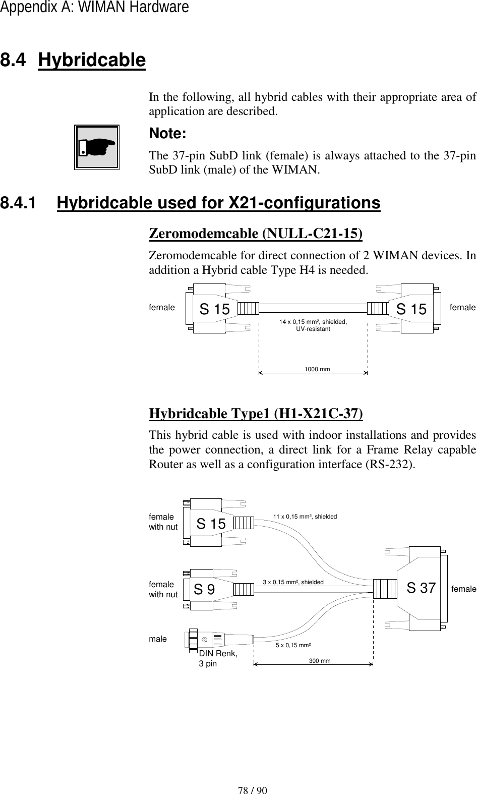
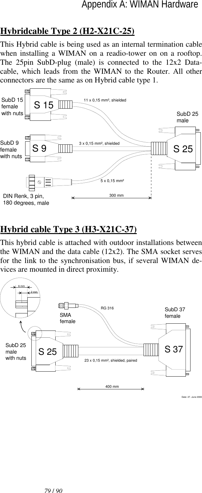
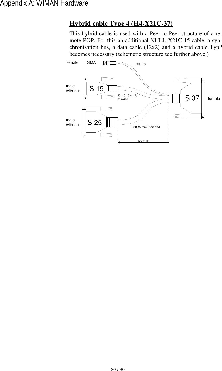
![71 / 90lAppendix A: WIMAN Hardware 8.2 Antenna systems Different antenna systems can be used with the WIMAN radio modem: Part.-No. 750081 750083 750001 750040 750061 750062 Matchcode AN-24-2MN360-FMEM AN-24-8MN360-NF3 AN-24-8PL76-SMAF AN-24-16PL24-NF AN-24-24PF8-NF AN-24-16PL85-NF Type Omni directional Omni direc-tional, 3° down-tilt planar planar paraflector Planar Gain [dBi] 2 8 8,5 16 24 16.5 Azimuth [degrees] 360 360 75 27 7 85 Elevation [degrees] > 60 13 60 27 10 6 Height [cm] 12 43 11 28 61 127 Width [cm] 3 3 9 28 92 8 Depth [cm] 3 3 3 4 38 5 Weight [kg] 0.04 0.2 0.1 0.9 2.4 2.1 Front/Back Ra-tio [dB] N/a n/a 20 40 31 25 VSWR (max.) 2 1.5 1.5 1.5 1.3 1.5 Connector FME male N female SMA female N female N female N female](https://usermanual.wiki/WIMAN-Systems/WIMAN2A24.Manual7/User-Guide-132665-Page-1.png)