WIMAN Systems WIMAN2A24 FHSS RF Modem User Manual Introduction to WIMAN technology
WIMAN Systems Inc FHSS RF Modem Introduction to WIMAN technology
UserManual.wiki
>
WIMAN Systems
>
WIMAN2A24 User Manual
>
Manual6
Contents
1.
Manual01
2.
Manual02
3.
Manual03
4.
Manual6
5.
Manual7
6.
Manualpage2
Manual6
Navigation menu
Upload a User Manual
Namespaces
Wiki Guide
HTML
PDF
Info
Views
User Manual
Discussion / Help
Navigation
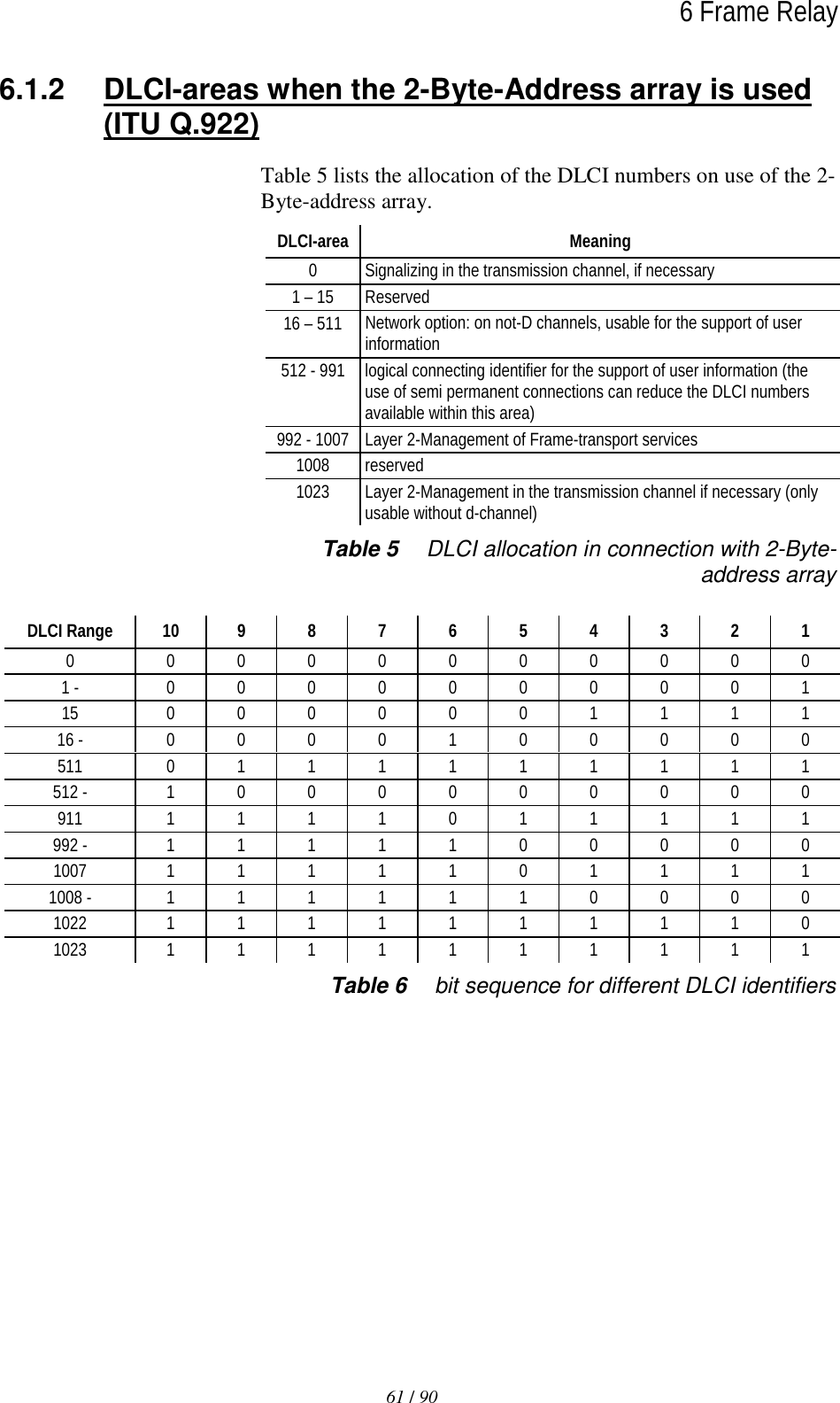
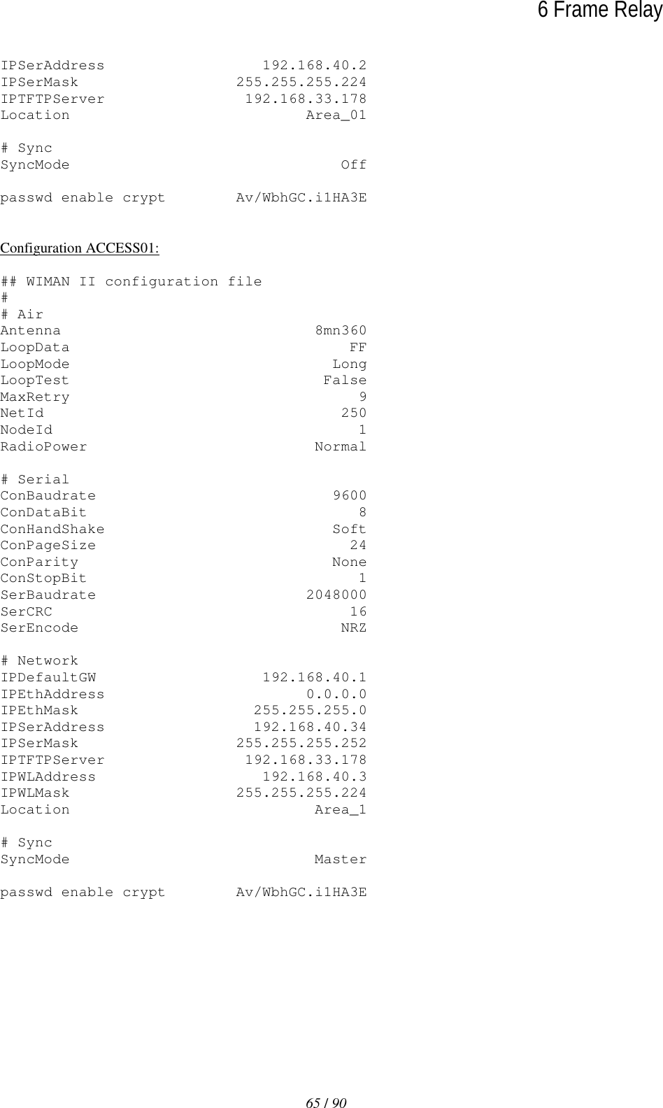
![60 / 90 6 Frame Relay The LCI value for the Frame Relay Router of the user is calcu-lated as follows: DLCIm = 512 + NodeId * 4 + m m = [0 ... 3] Table 4 lists the valid DLCI numbers for appropriate node iden-tifiers (NodeId) on use of the 2-Byte-Frame of Relay address ar-ray. WIMAN NodeId DLCI array Note 0 512 – 515 reserved (WIMAN STAR) 1 516 – 519 2 520 – 523 3 524 – 527 4 528 – 531 5 532 – 535 6 536 – 539 7 540 – 543 8 544 – 547 9 548 – 551 10 552 – 555 11 556 – 559 12 560 – 563 13 564 – 567 14 568 – 571 15 572 – 575 Table 4 NodeId with 2-Byte-Frame Relay address array In the following, the implementation of the Frame of Relay Pro-tocol within the WIMAN software is listed briefly. Exclusively the static software-Version of the WIMAN STAR supports the Frame Relay Protocol with the following characteristics: • The maximum size of the Frame Relay information field amounts to 4096 byte. • The WIMAN star rejects Frame Relay framework with in-valid DLCI number (transmitter and receiver). DLCI value calculation Frame Relay-support of the WIMAN Software](https://usermanual.wiki/WIMAN-Systems/WIMAN2A24.Manual6/User-Guide-132664-Page-10.png)