WIMAN Systems WIMAN2A24 FHSS RF Modem User Manual Introduction to WIMAN technology
WIMAN Systems Inc FHSS RF Modem Introduction to WIMAN technology
UserManual.wiki
>
WIMAN Systems
>
WIMAN2A24 User Manual
>
Manual02
Contents
1.
Manual01
2.
Manual02
3.
Manual03
4.
Manual6
5.
Manual7
6.
Manualpage2
Manual02
Navigation menu
Upload a User Manual
Namespaces
Wiki Guide
HTML
PDF
Info
Views
User Manual
Discussion / Help
Navigation
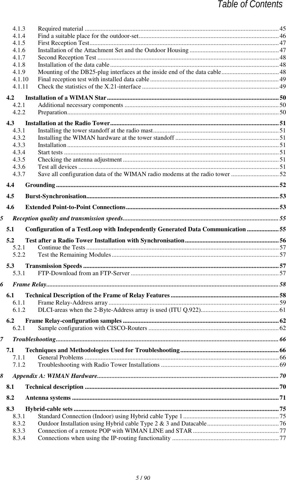
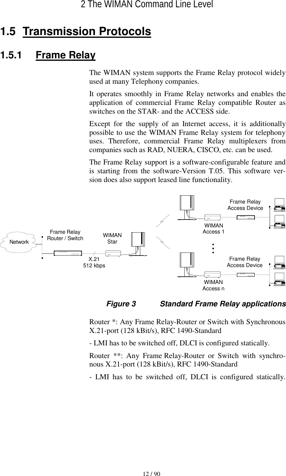
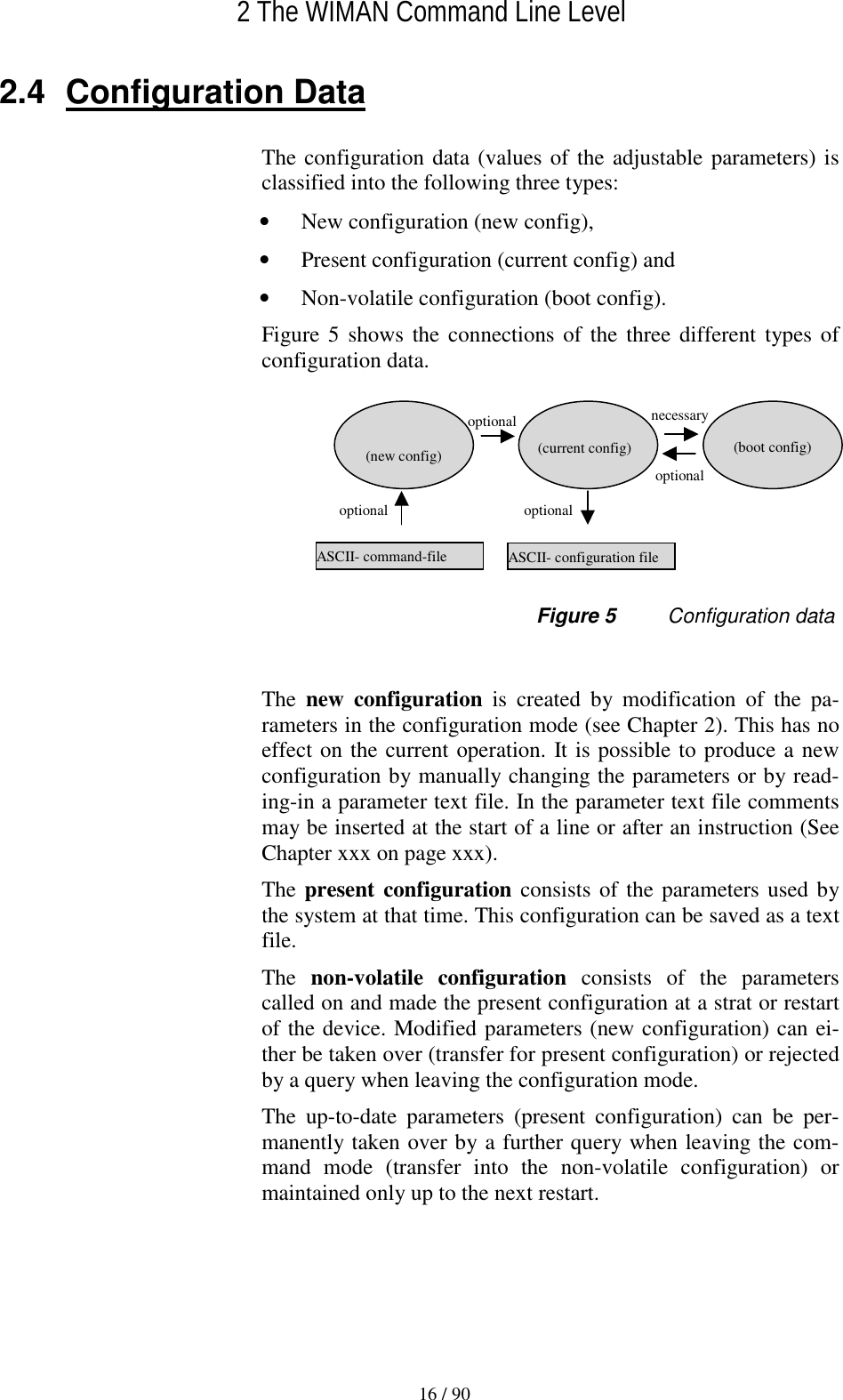
![2 The WIMAN Command Line Level 14 / 90 2.2 Passwords Passwords serve to protect the WIMAN from unauthorized ac-cess to the command line level in the different authorization lev-els. All passwords must have a length from four to eight charac-ters. For the passwords the following characters may be used: " a... z ", " A... z ", " 0... 9 ", " - ", " @ ", "?", " \ ", " [ ", " ] ", " < ", " > ". NOTE: The WIMAN DOES acknowledge case sensitivity characters for passwords. Attention Typing in of any other characters than the ones mentioned above may lead to a reset of the WIMAN shell. If no password is assigned for the authorization level one, the command line appears when the WIMAN is switched on. Oth-erwise you are asked to enter a password to access the command line level one. A password for authorization level two is always required. This password cannot be deleted, however it is possible to modify this password. In case of a false configuration or a forgotten password in the lowest authorization level (e.g. user authorization level) quali-fied personnel are needed to access the unit (e.g. Provider). It is possible to gain access directly to level two by entering the des-ignated password for that level. With suitable instruction (see chapter 3.5.1, on page 40) you can reset the password for authorization level one. If, for any reason, you are unable to arrive at the necessary au-thorization level any longer and you are thus closed out of the device, it is possible to gain access with a master password. The master password can only be used after the third unsuccessful access attempt and can only be made via the serial interface. Further information on this issue can be obtained from your WIMAN Distributor. Attention: The input of the master password can be executed exclusively over the RS-232 port and results in resetting of all parameters to their factory settings. A reconfiguration of the device will be necessary afterwards.](https://usermanual.wiki/WIMAN-Systems/WIMAN2A24.Manual02/User-Guide-132635-Page-14.png)
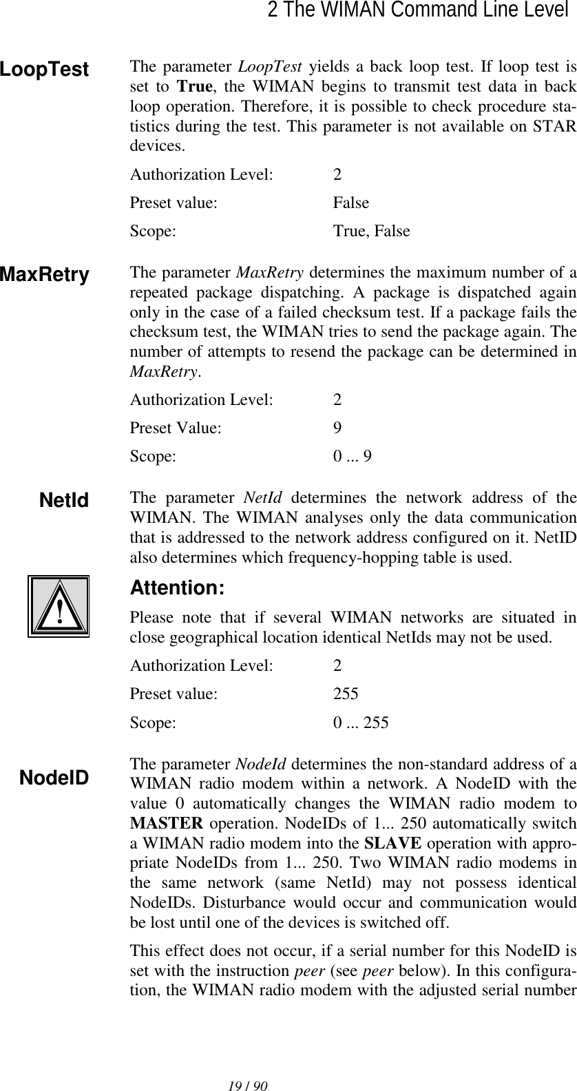
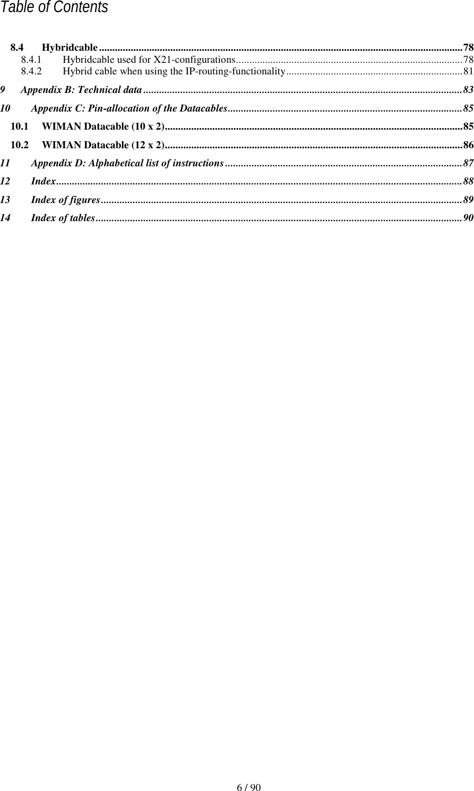
![2 The WIMAN Command Line Level15 / 90l2.3 Operation Modes On the command line level, the following operating modes are differentiated with respect to each authorization level: • Command mode and • Configuration mode. In command mode you can view the accepted parameters of the present configuration (current config) as well as give the ac-cepted commands for this mode and authorization level (see Chapter 2.6.1 on page 25). In configuration mode you may change only the parameters al-lowed for that specific authorization level. The system software indicates these parameters as “new con-figuration” (new config). You may render certified instructions for this level and this mode. Figure 4 shows how to switch between the different authoriza-tion levels and operation modes. pw password [] optional (n) Authorization level en enable Figure 4 Diagram of the different operating modes serial connection / Telnet Reset pw ← ↓ [pw] ↑ exit ↑ exit ↓ Reset Config ← pw → Command Mode (1) → en pw Command Mode (2) ↓ config ↑ exit ↓ config ↑ exit Config Mode Config Mode](https://usermanual.wiki/WIMAN-Systems/WIMAN2A24.Manual02/User-Guide-132635-Page-15.png)