WJ Communications SX1115 User Manual 6030cn
WJ Communications, Inc. 6030cn
Contents
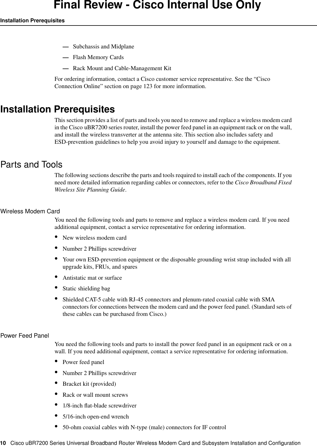
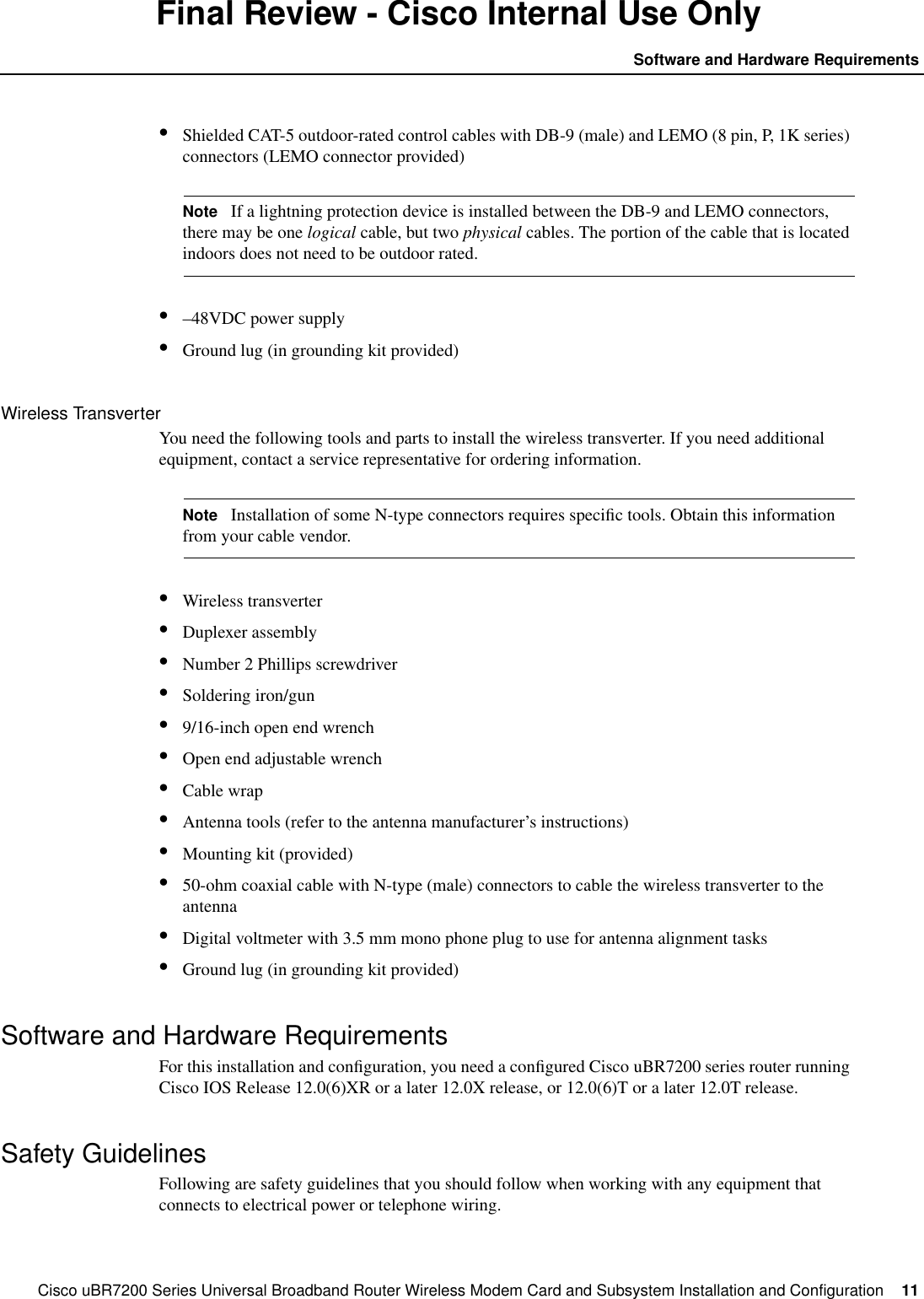
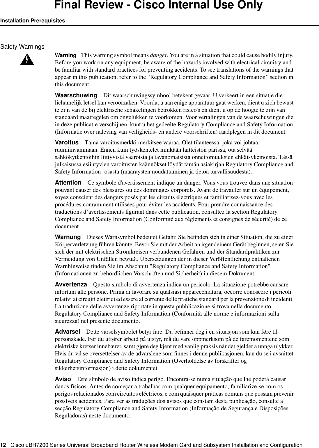
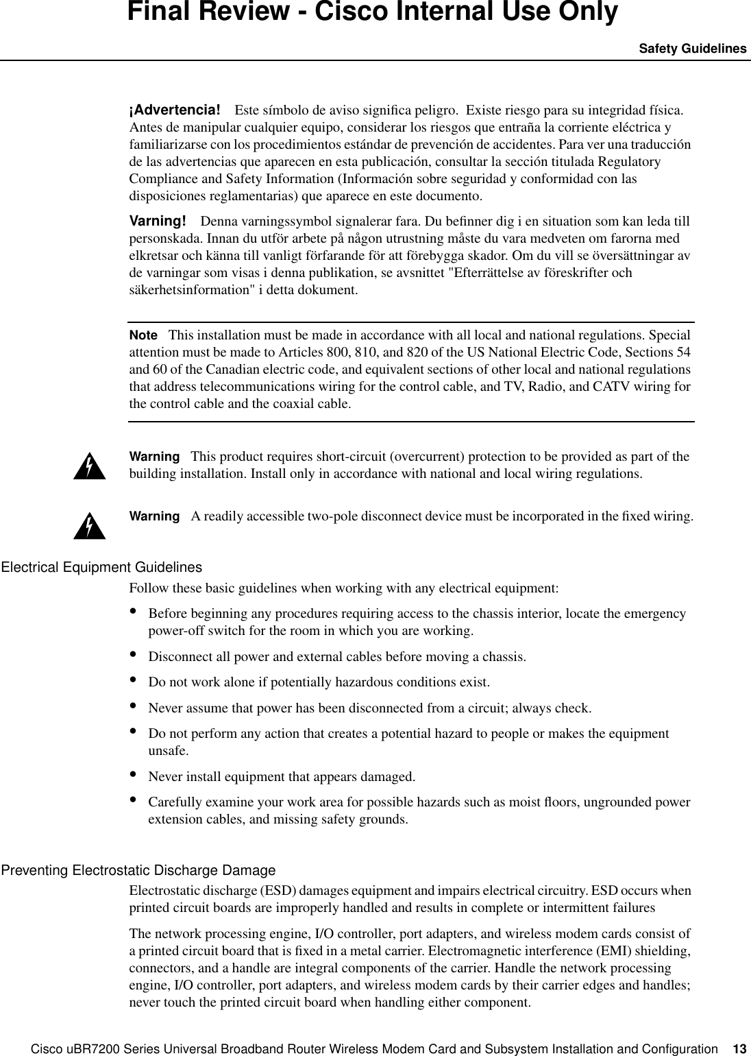
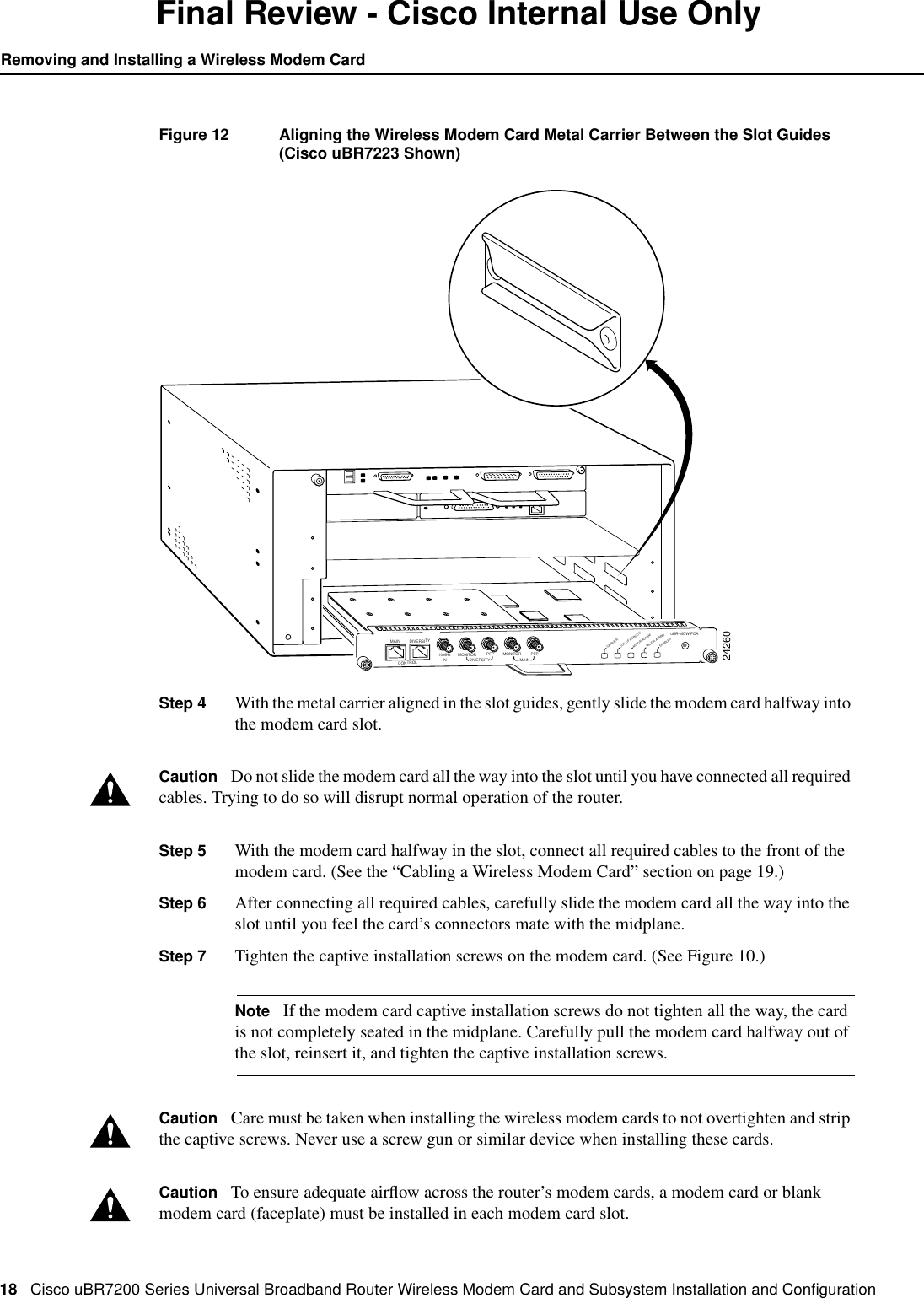
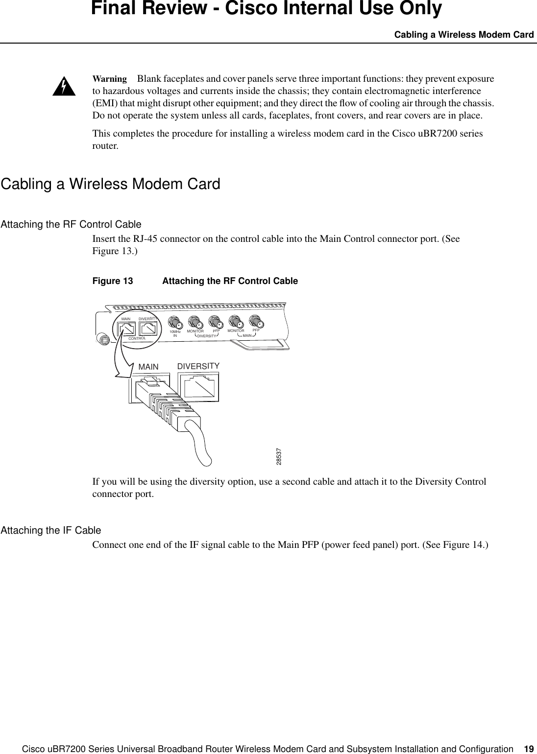
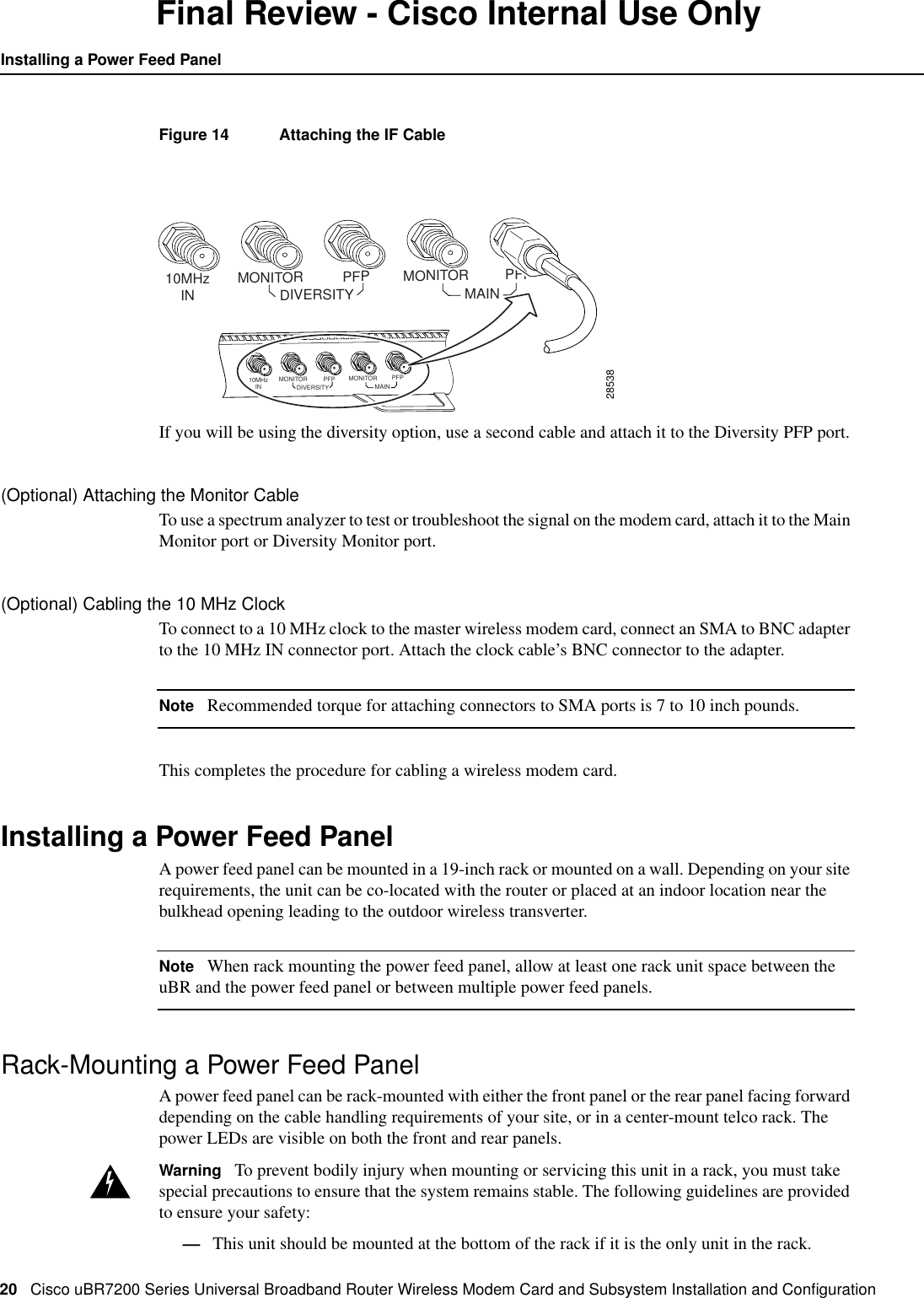
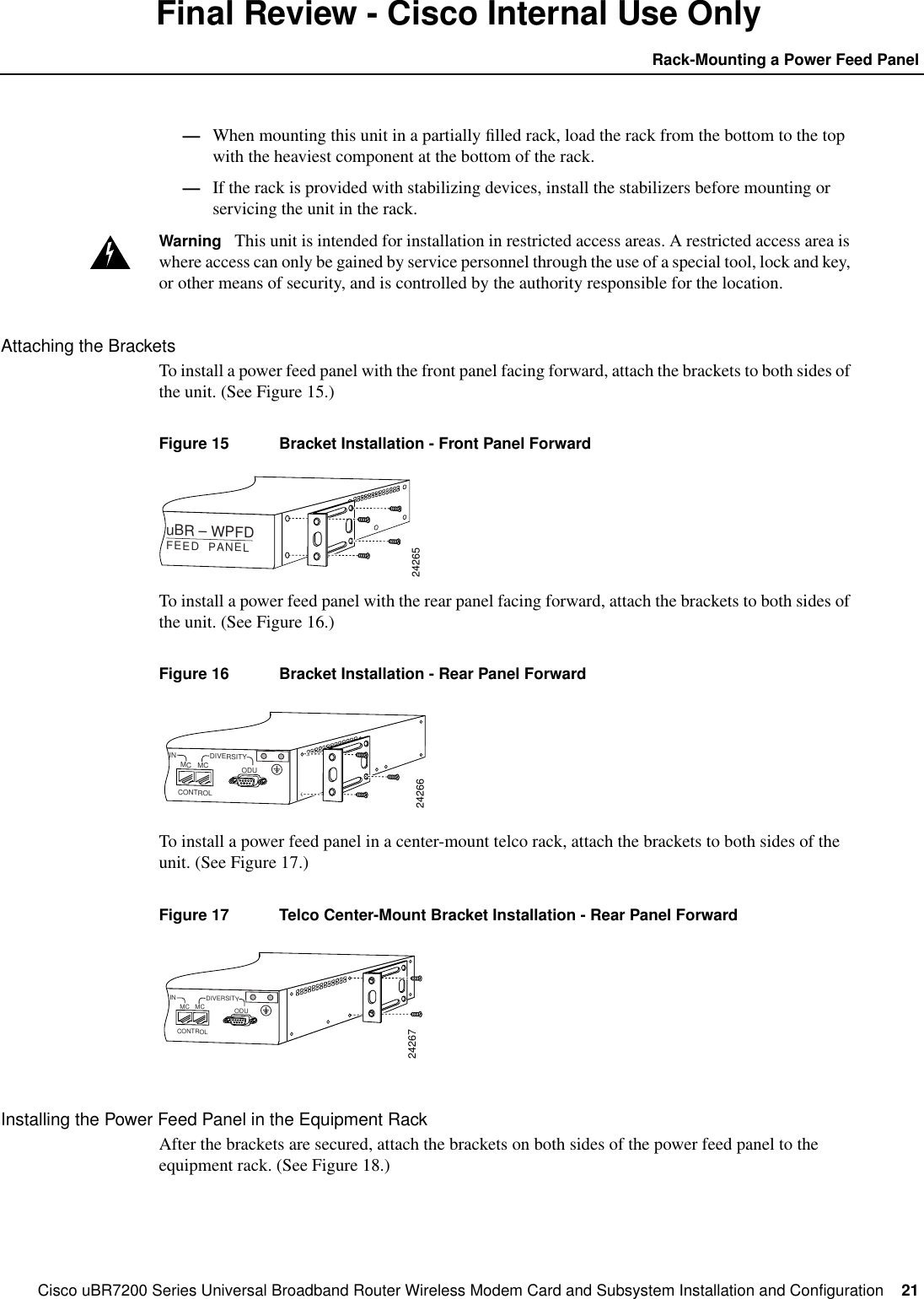
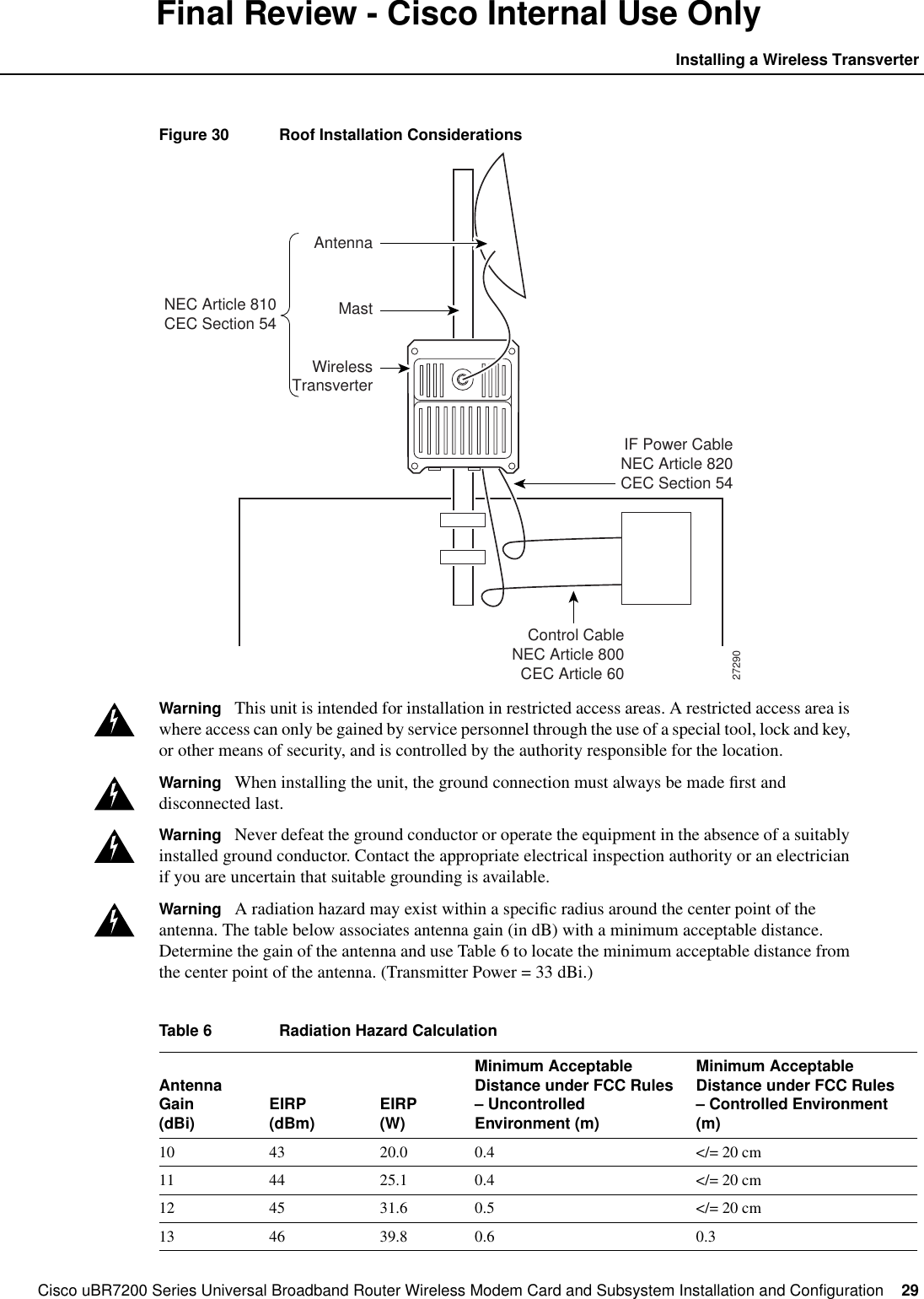
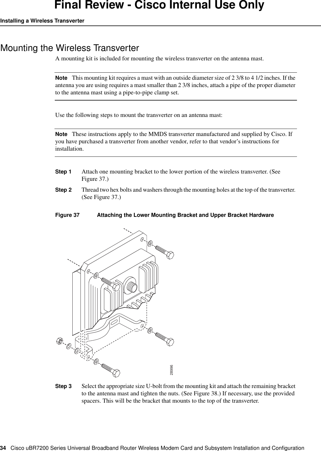
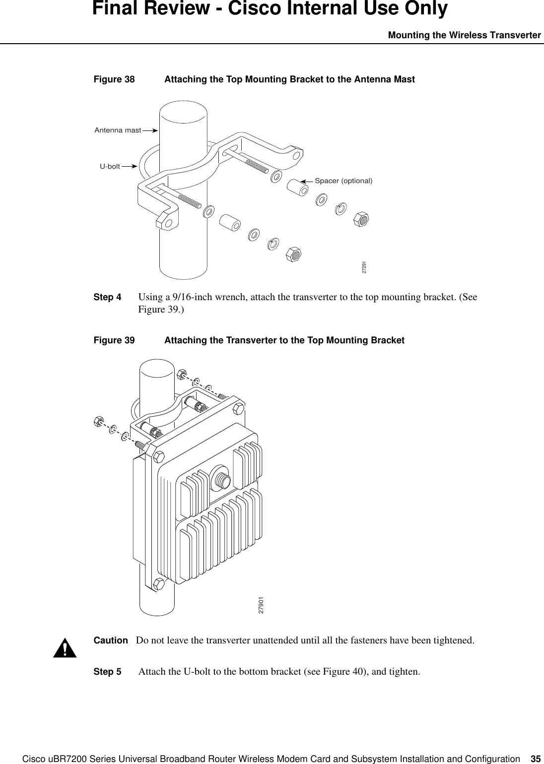
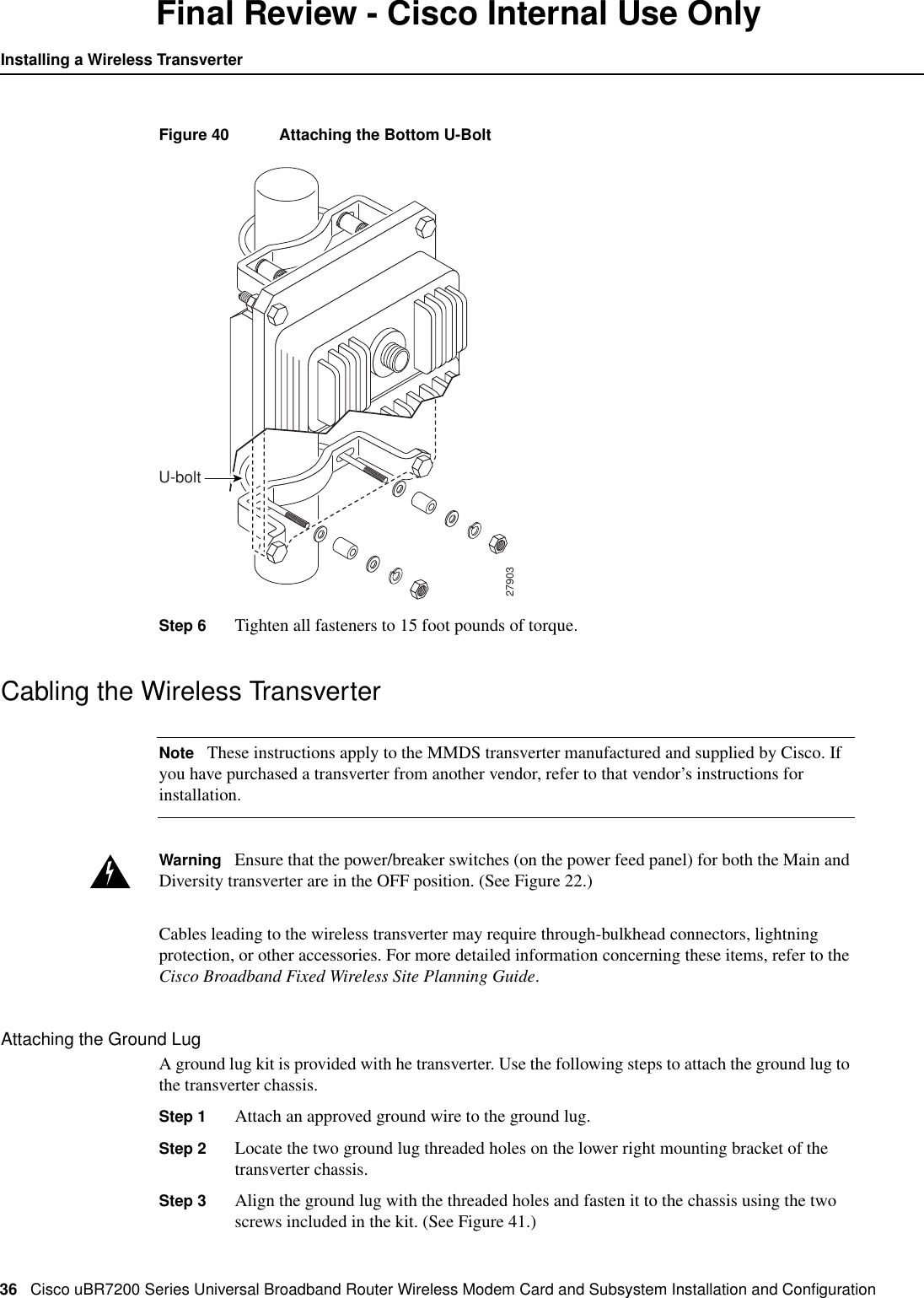
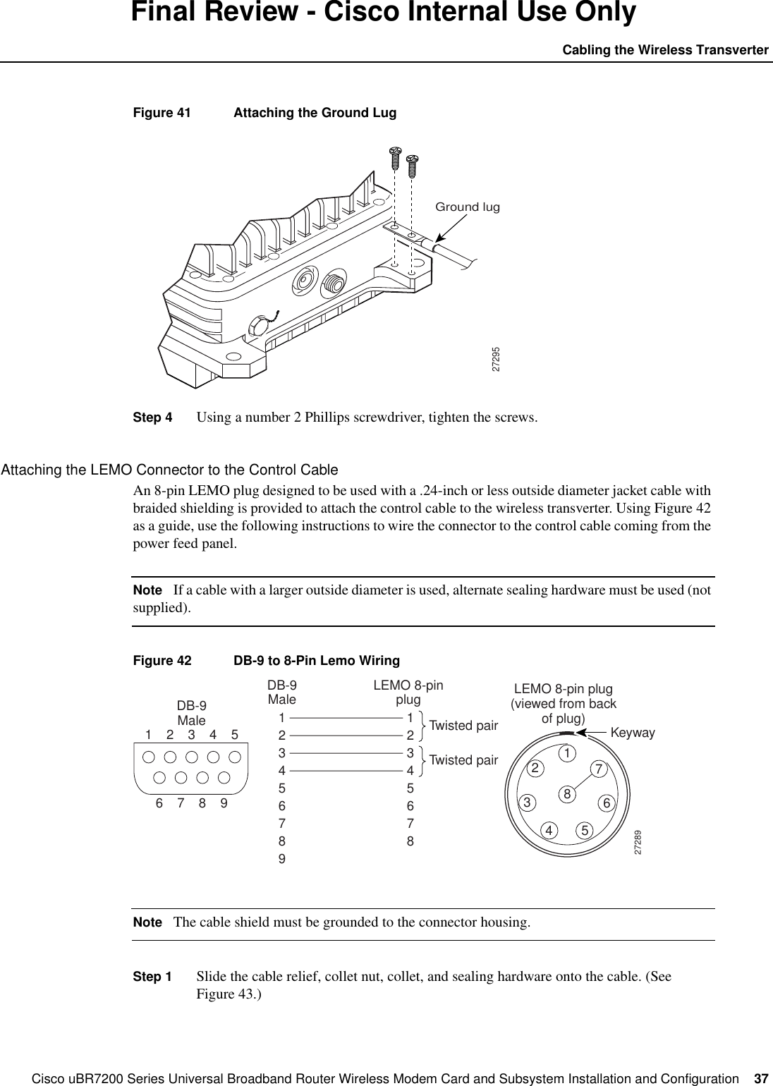
- 1. Excerpt from Cisco manual showing antenna mounting
- 2. Suhner antenna data
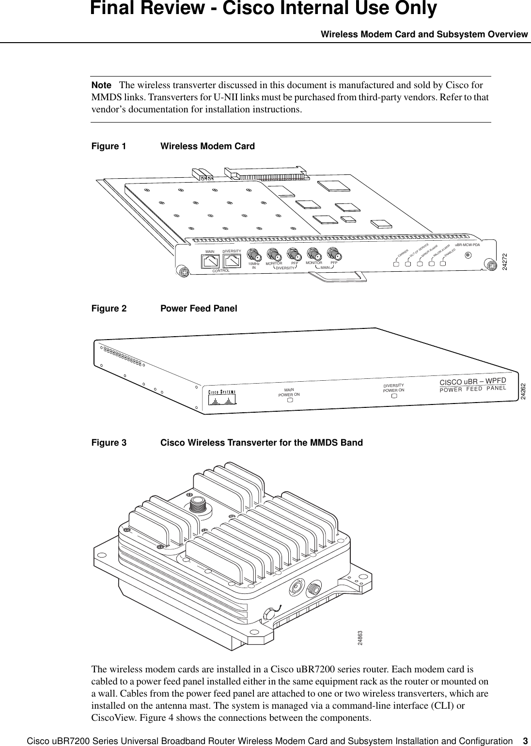
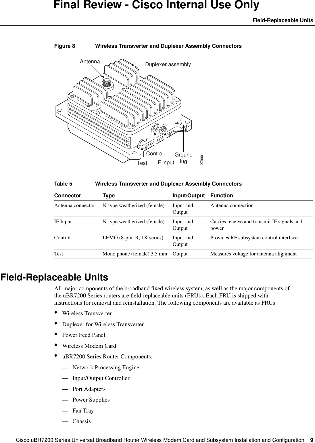
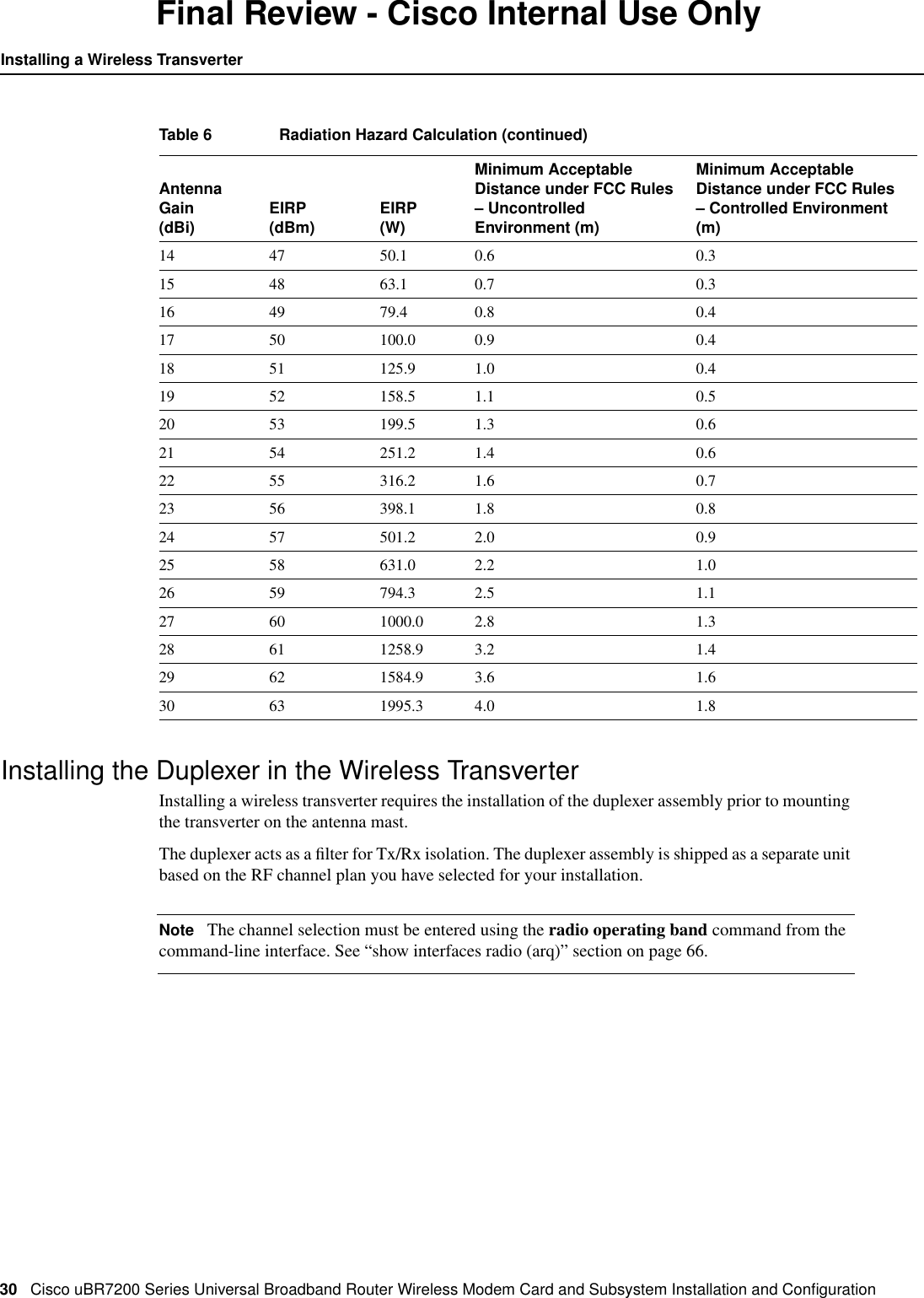
- 3. Hardware manual will be same for UNII but with MPE values shown in WJ test repor
- 4. RadioWave antenna data, page 1
- 5. RadioWave antenna, page 2
- 6. RadioWave antena, page 3
- 7. RSI Comsat patch antenna data, page 1
- 8. RSI patch, page 2
- 9. RSI patch, page 3
- 10. RSI patch, page 4
- 11. Antnenna mount detail, RadioWave 4 ft dish
- 12. Antennas used during tests (antenna list)
- 13. 14 dBi corne antenna data sheet
- 14. Response to 2 Dec request re MPE
- 15. WJ instruction manual with page 7 to be replaced
- 16. Mobil Mark antenna info
- 17. Radio Wave antenna info
- 18. Includes multiple antenna location instructions to installer
- 19. pdf version of MPE info from WJ
- 20. Copy of email sent to you and Kwok re MPE
- 21. Revised antenna installation instruction
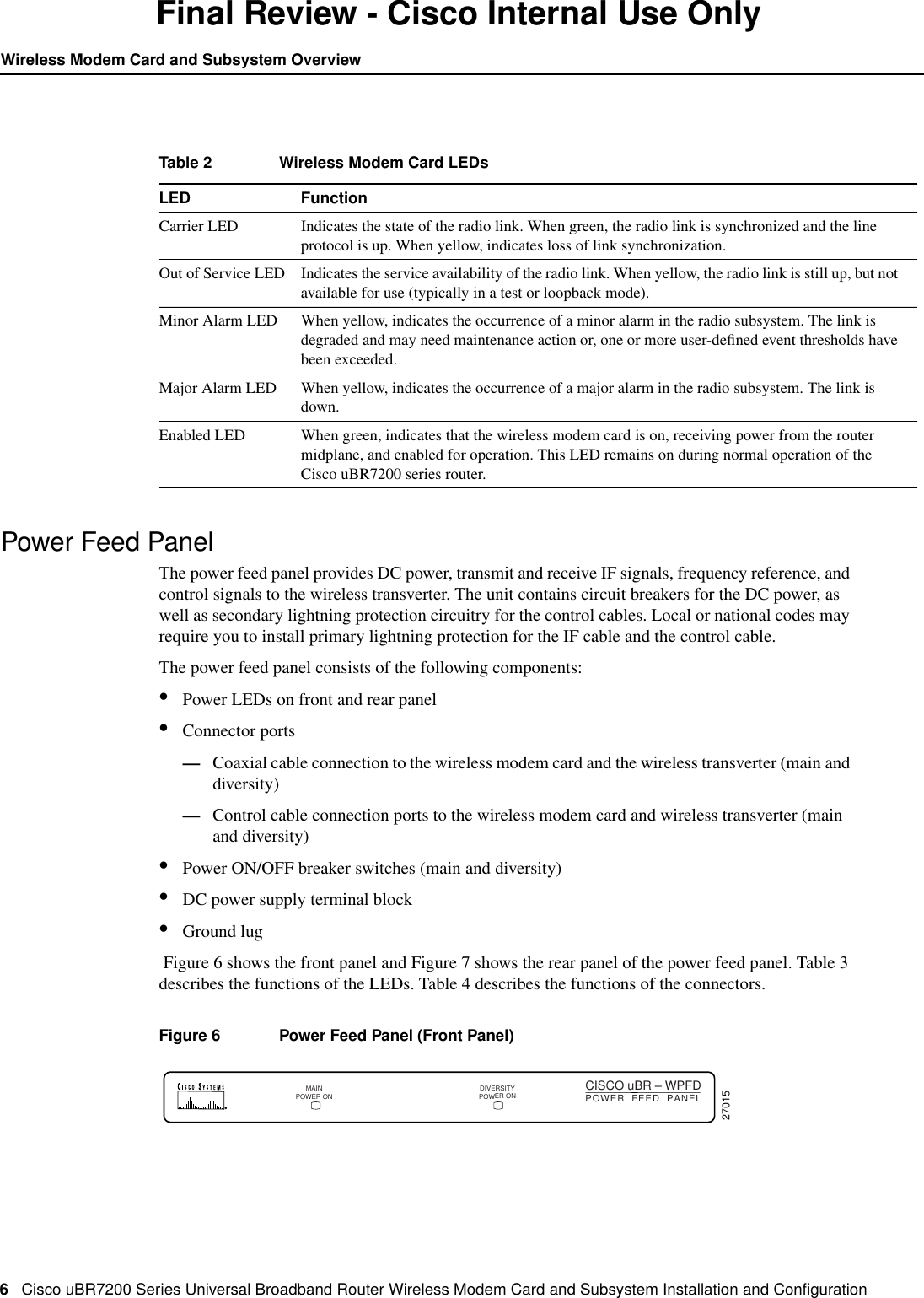
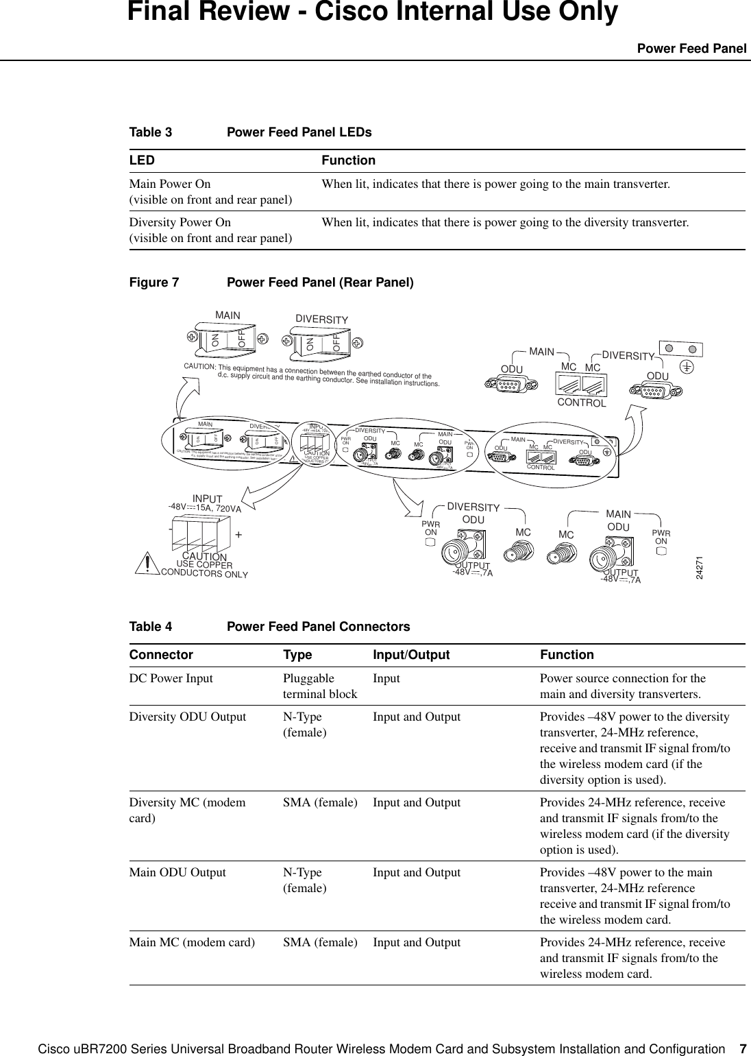
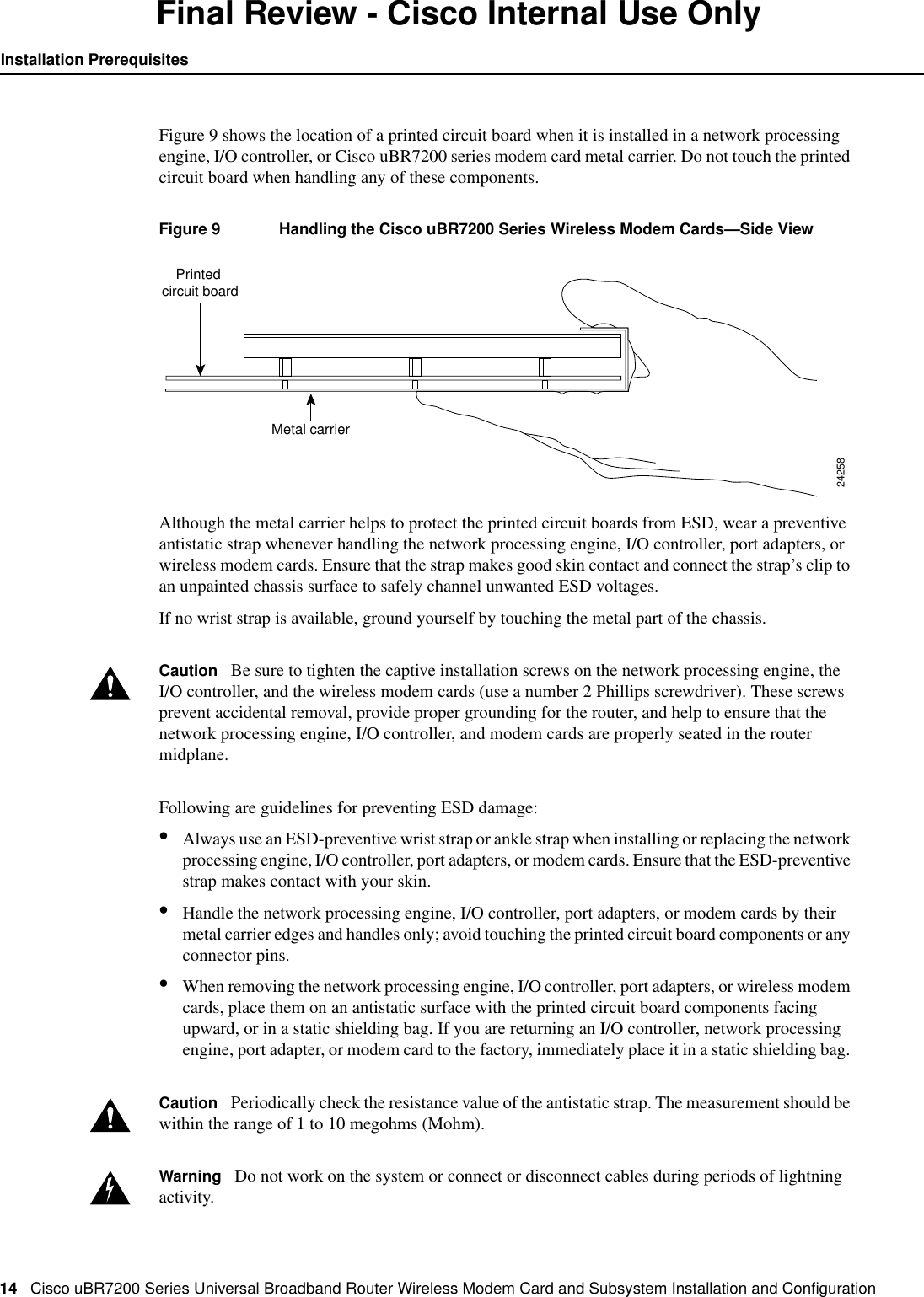
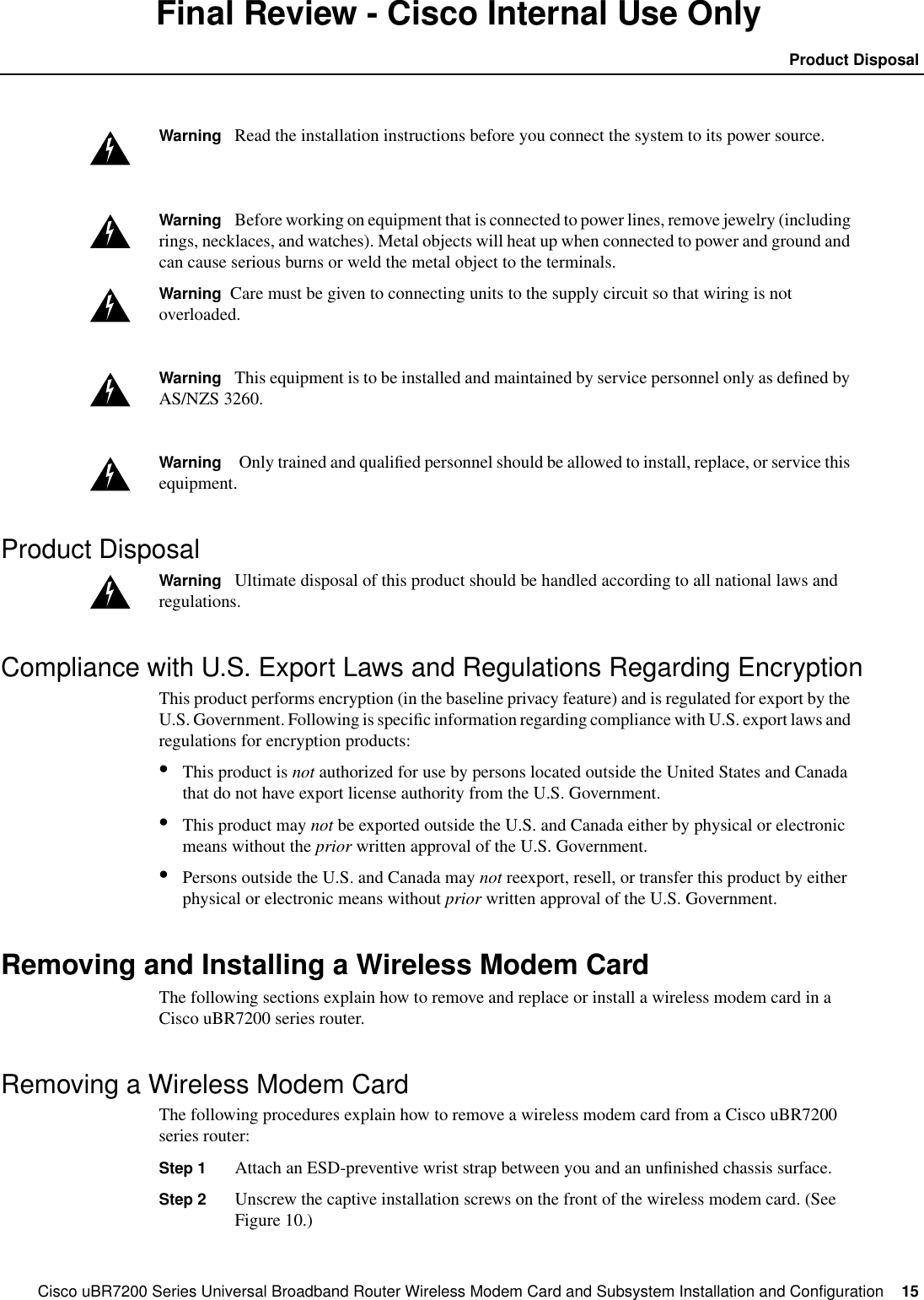
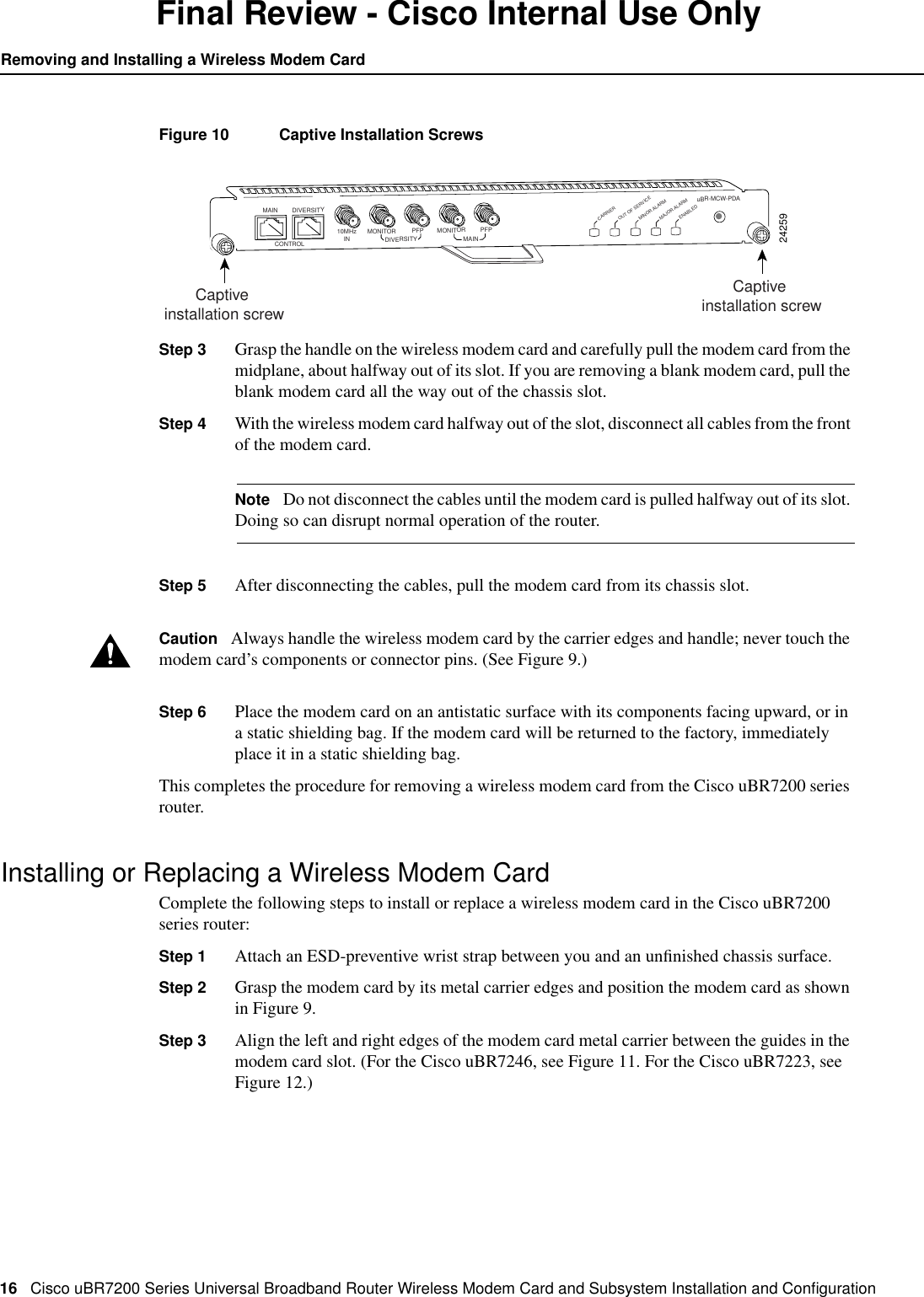
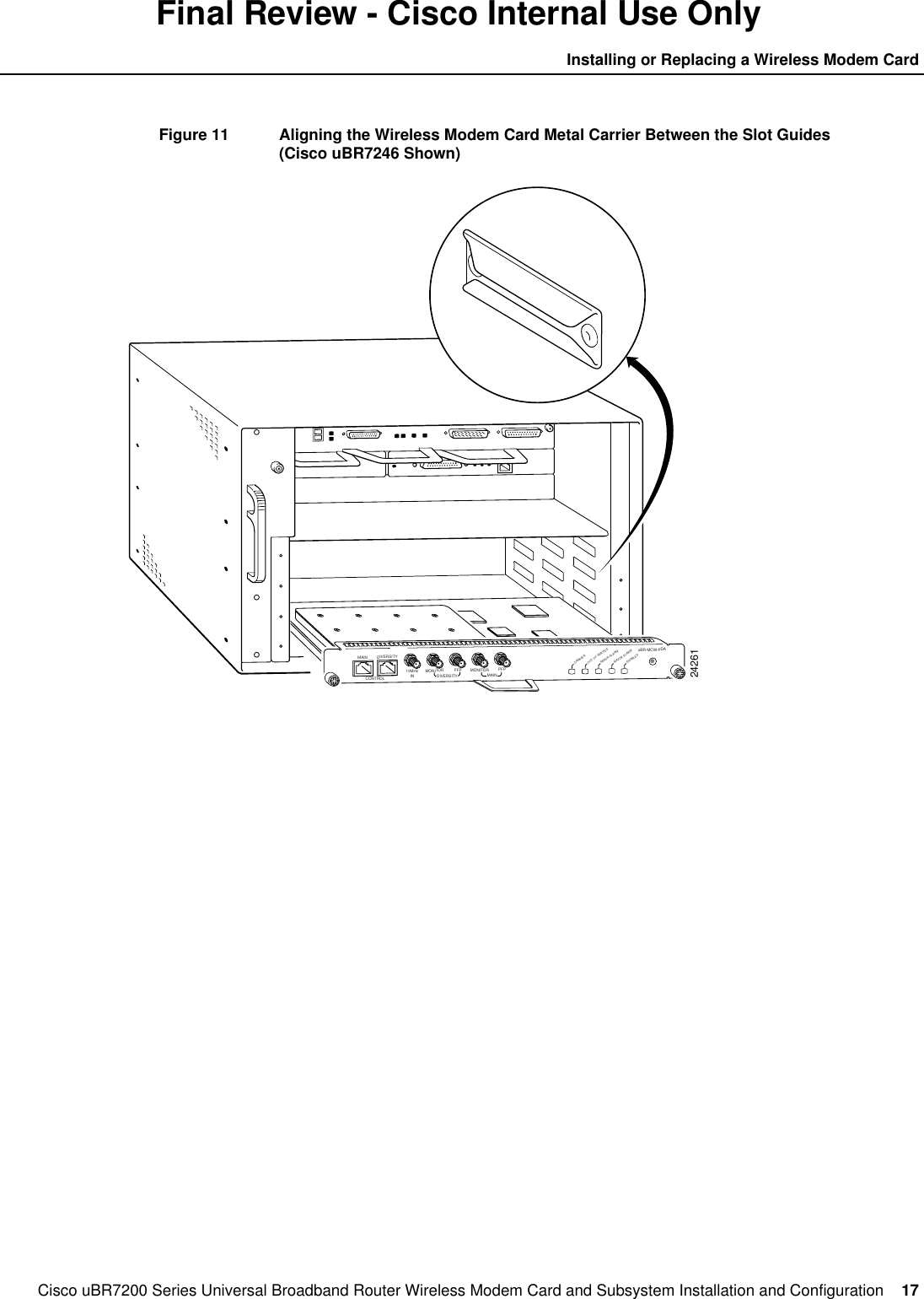
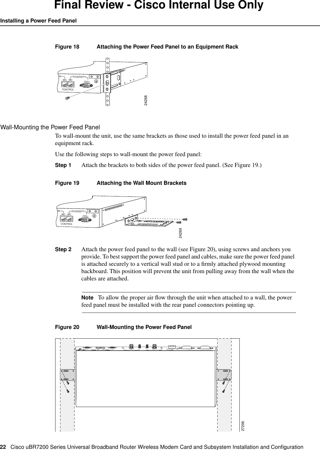
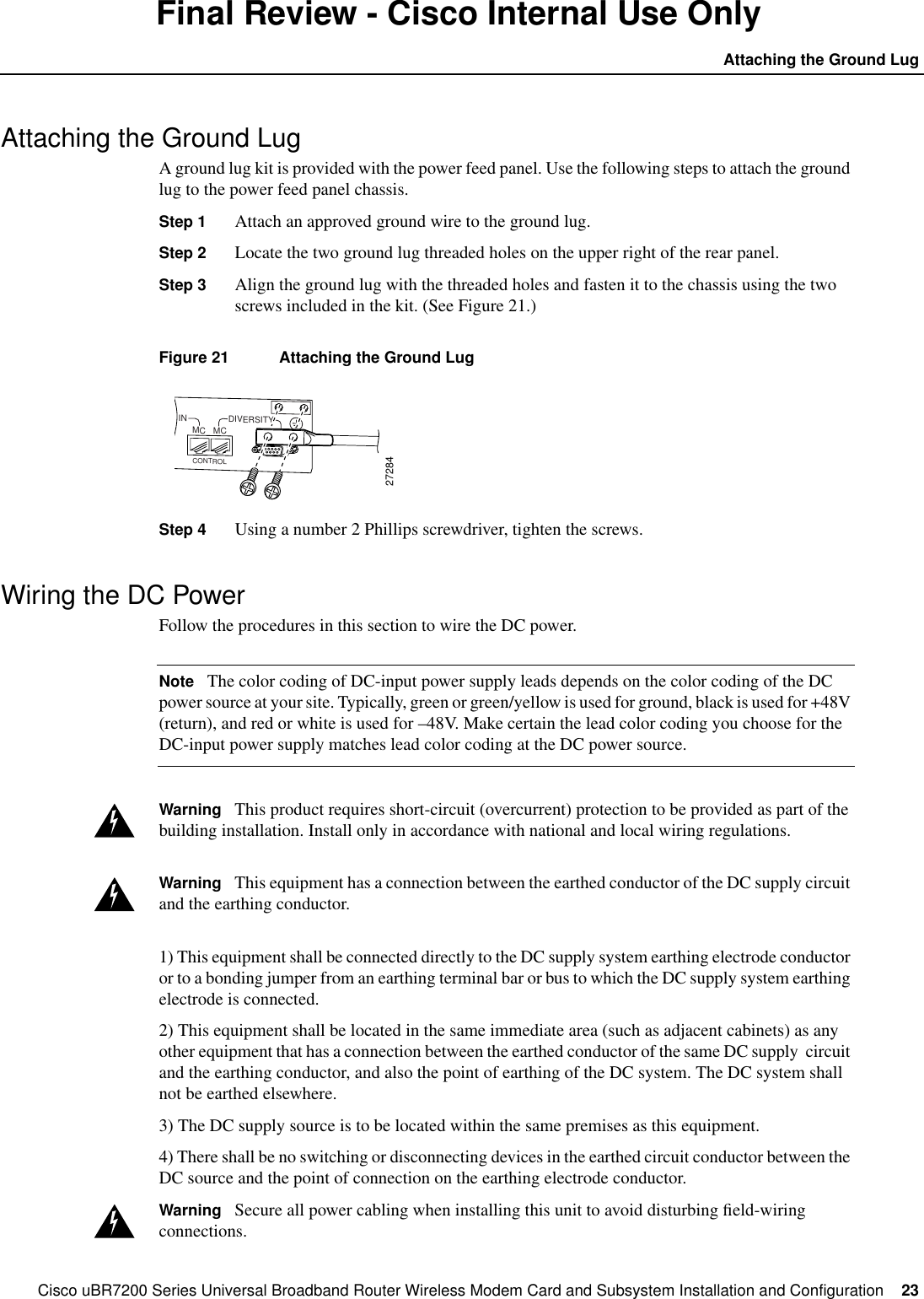
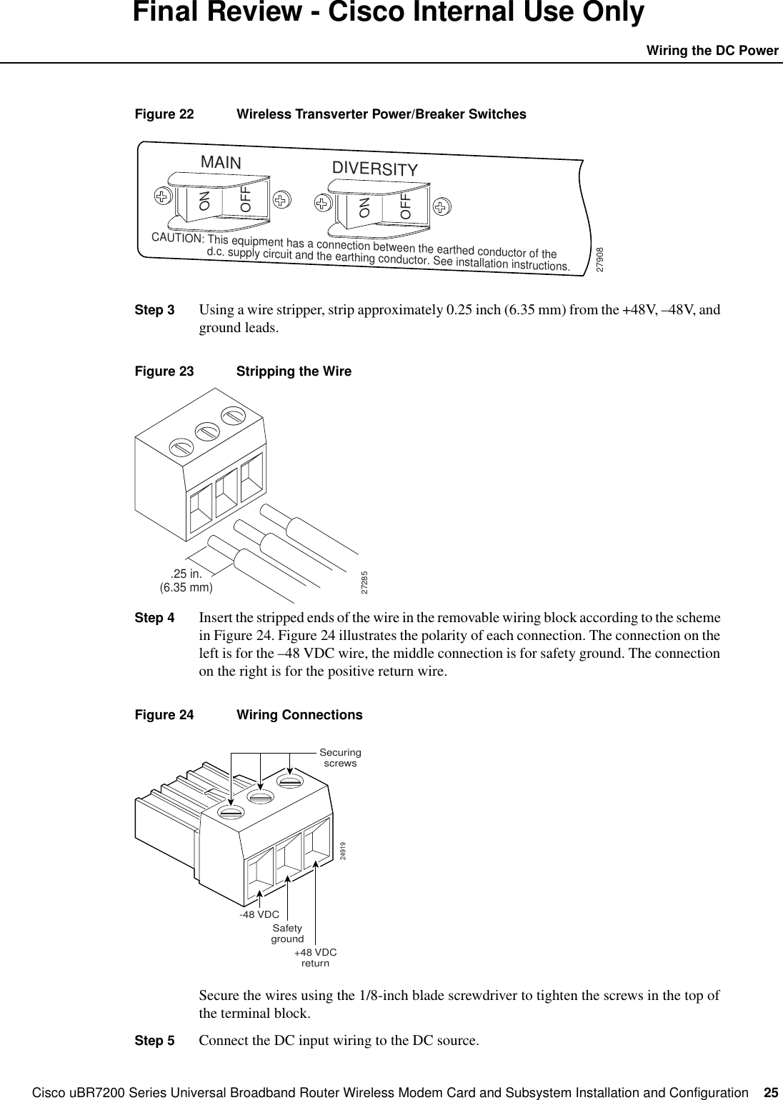
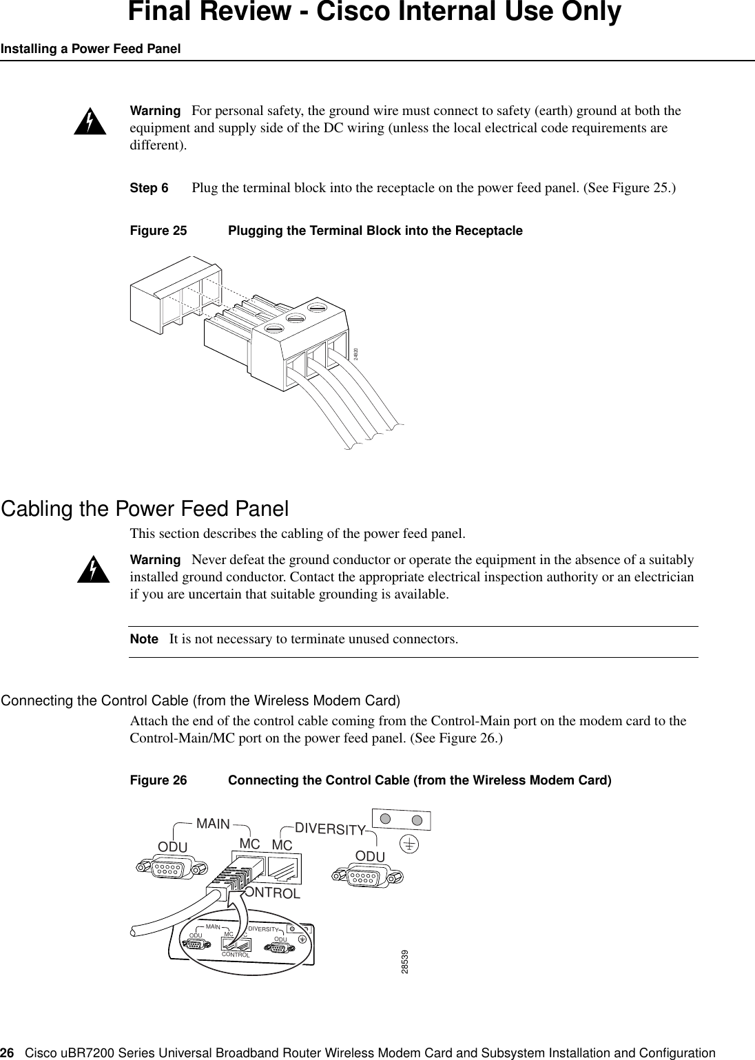
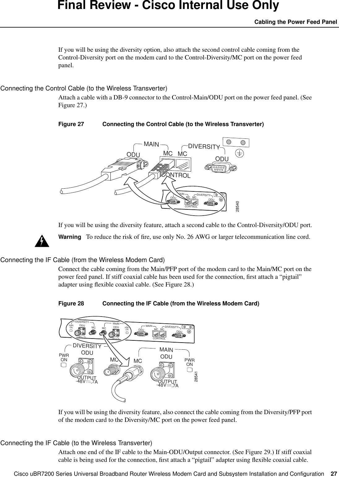
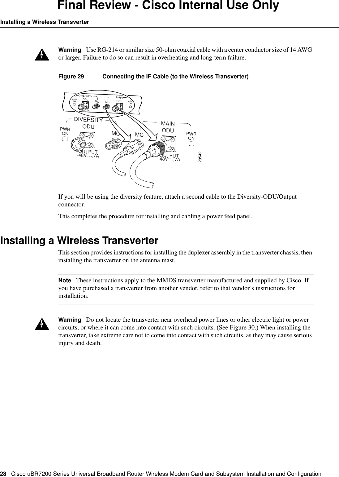
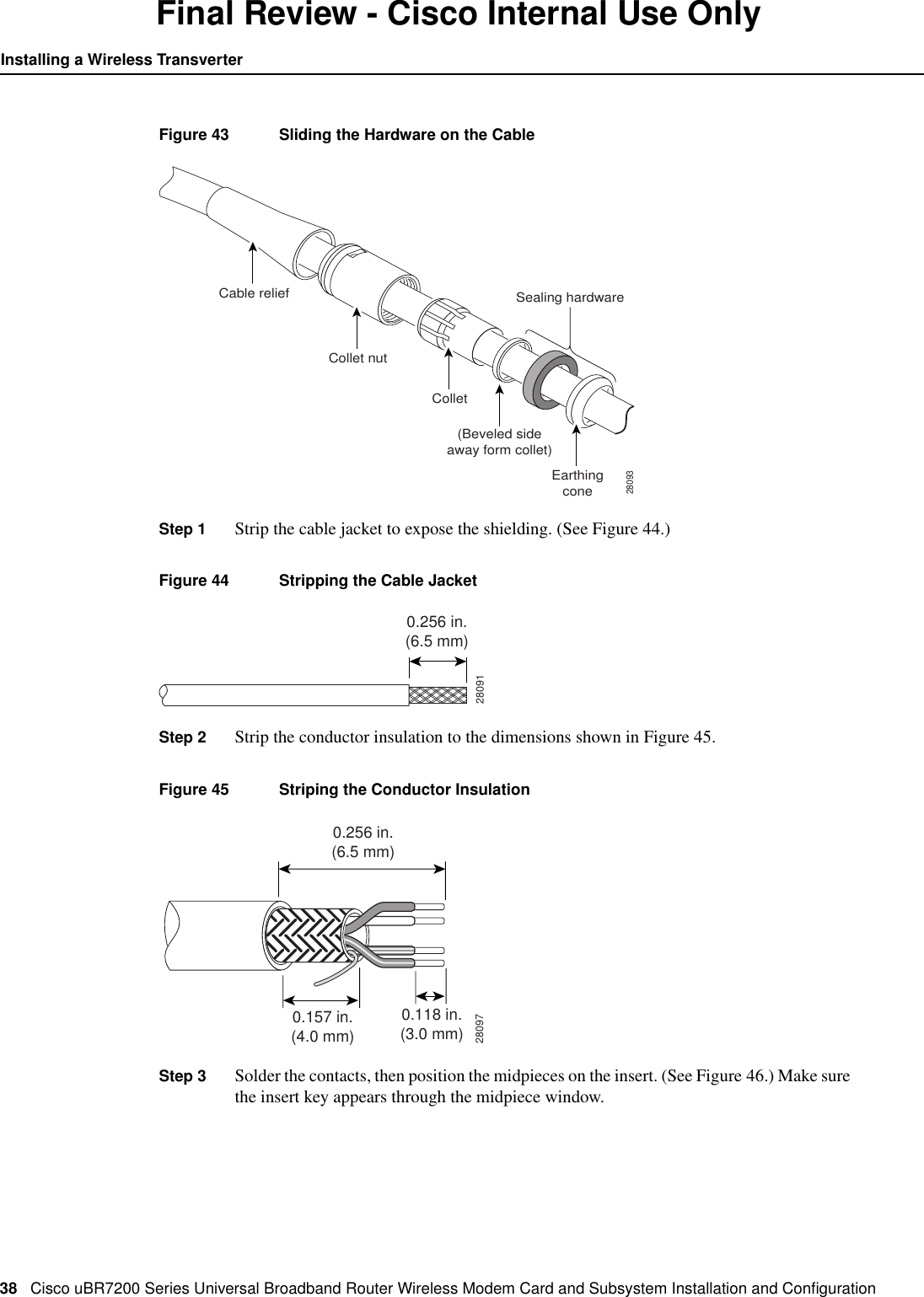
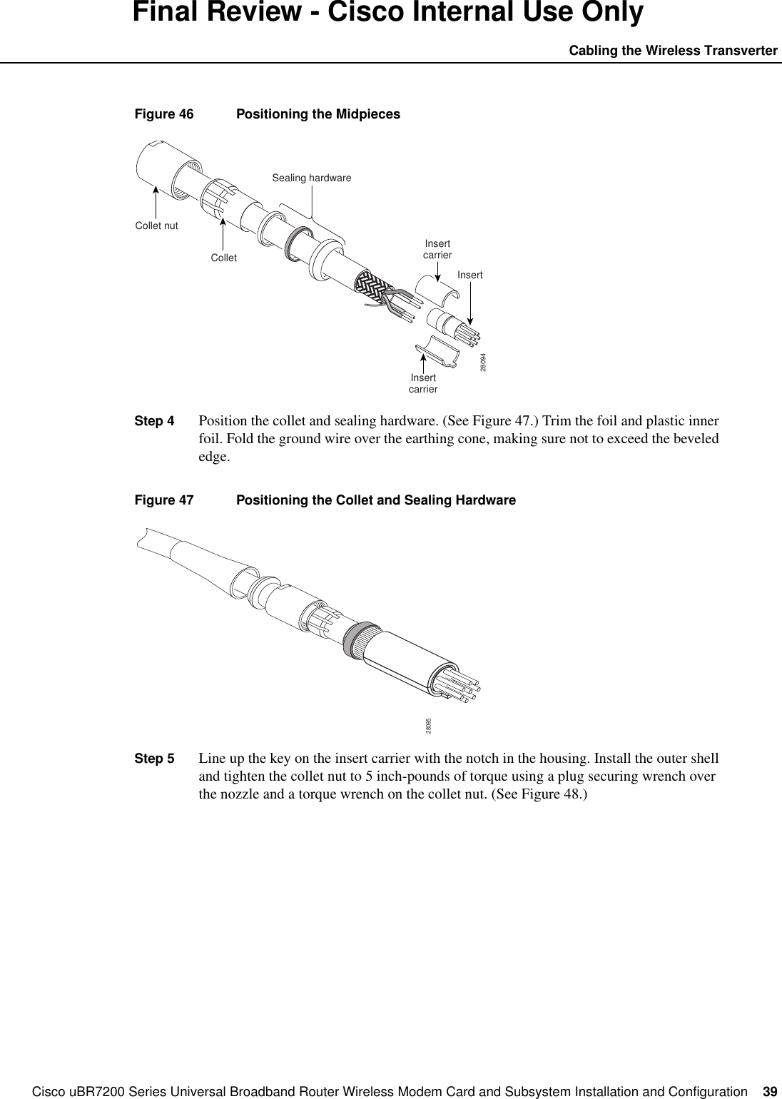
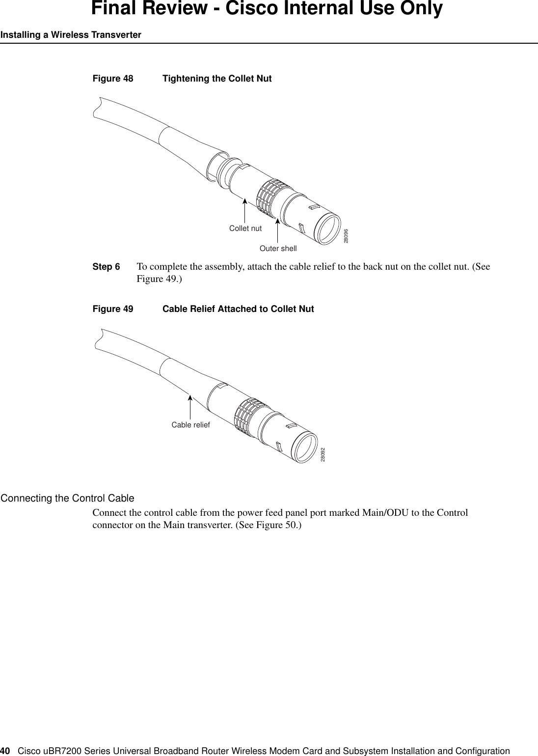
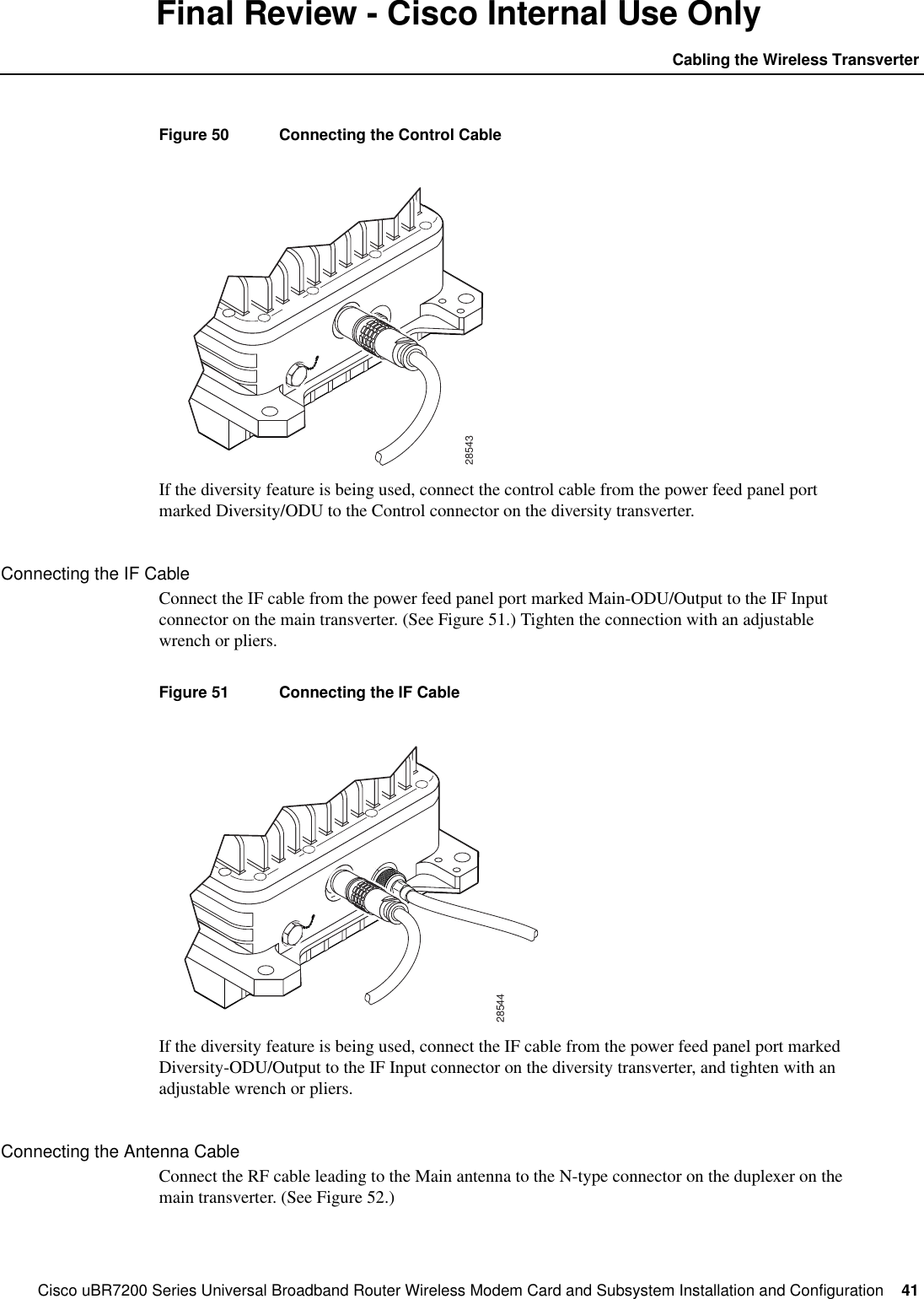
Hardware manual will be same for UNII but with MPE values shown in WJ test repor