Wireless Seismic 00106 Wireless remote seismic disturbance sensor User Manual DeploymentGuide
Wireless Seismic, Inc. Wireless remote seismic disturbance sensor DeploymentGuide
Contents
- 1. User Manual Part 1
- 2. User Manual Part 2
User Manual Part 2
R01.i RT System 2 v2.3 Deployment Guide 151
© 2010-2014 Wireless Seismic, Inc. All rights reserved.
C. Radio Specifications
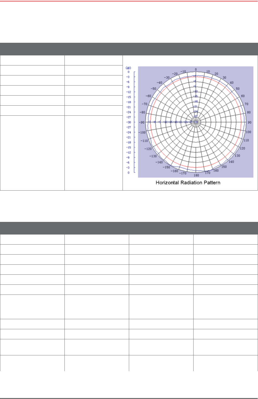
Antenna Specifications
Maximum Power 100 Watts
Connector N-Style Jack
Height 10.6"
Weight 0.5 lbs
Horizontal Beamwidth 360°
Rated Wind Velocity 135 mph
Operating Temperature -22°F to 158 °F
-30 to 70 °C
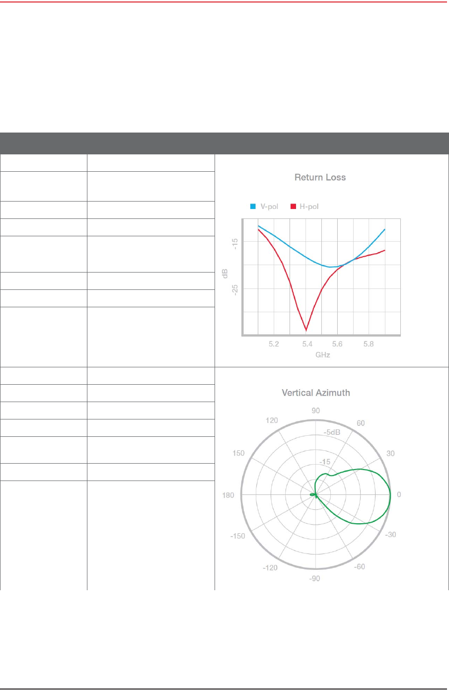
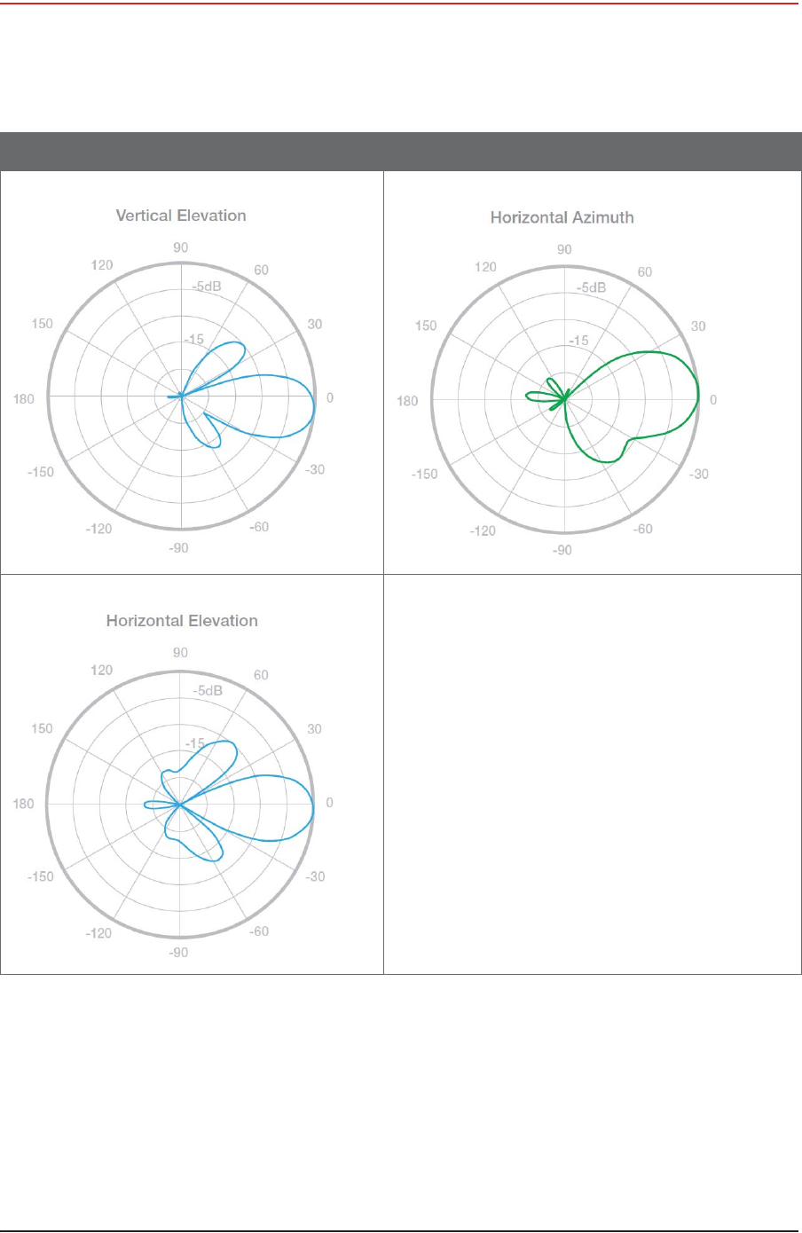
Table C–1 Antenna Specifications, 6 dBi (65-0179) (cont.)
Item Description Radiation Patterns
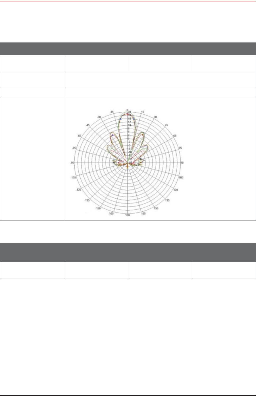
Table C–2 Antenna Specifications, 13 dBi (65-0177)
Parameter Min Typ Max
Frequency Range 5150 MHz 5825 MHz
Gain 19 dBi
Horizontal Beamwidth 16 Deg
Vertical Beamwidth 16 Deg
Front to Back 30 dB
Cross Polarization 25 dB
VSWR
• 5150-5350MHz
• 5470-5825MHz
2.0:1
1.5:1
Impedance 50 OHM
Input Power 100W
Operating Temperature -40 ºF
-40 °C 158 °F
70 °C
Pole Size 1 in
25 mm 2.5 in
64 mm
152 RT System 2 v2.3 Deployment Guide R01.i
© 2010-2014 Wireless Seismic, Inc. All rights reserved.
C. Radio Specifications
Antenna Specifications
C.1.2 Rocket Recorder Antenna
The recorder station backhaul using the Ubiquiti Rocket radio supports a 13 dBi antenna. This
antenna is a 2x2 Dual Polarity MIMO Omnidirectional Antenna that provides 360 degree
coverage.
Weight 17.6 oz
0.5 kg
Dimension
(L x W x Thick) 7.5 x 7.5 x 0.8 in
190 x 190 x 20 mm
Bracket Tilt 45 Deg
Radiation Pattern
Table C–2 Antenna Specifications, 13 dBi (65-0177) (cont.)
Parameter Min Typ Max
Table C–3 Antenna Wind Loading, 13 dBi (65-0177)
Parameter Area 100 mph
161 kph 125 mph
201 kph
Wind Loading 56 sq in
0.04 sq m 14 lbs
6.4 kg 22 lbs
10 kg
R01.i RT System 2 v2.3 Deployment Guide 153
© 2010-2014 Wireless Seismic, Inc. All rights reserved.
C. Radio Specifications
Antenna Specifications
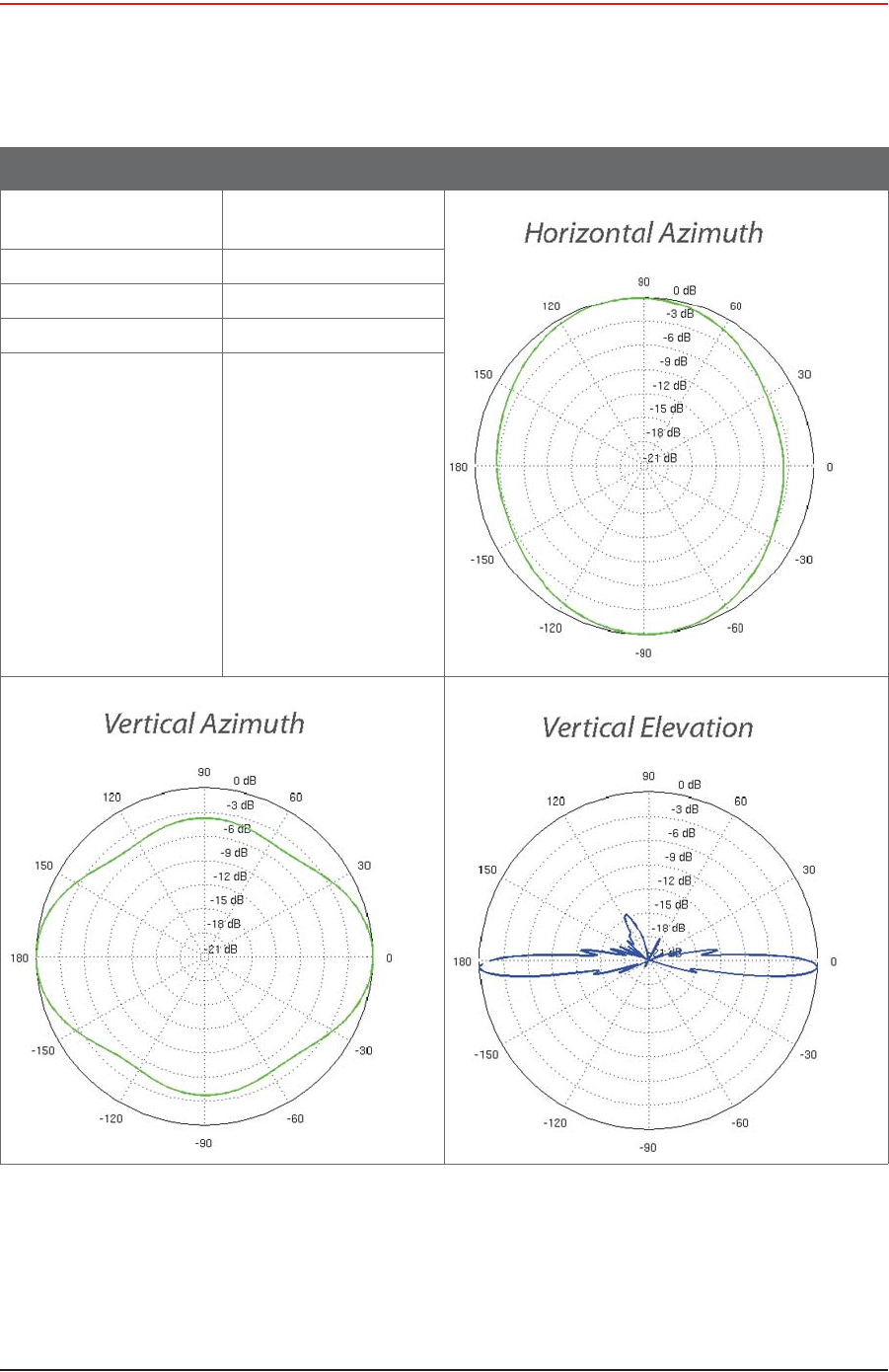
The supported recorder antenna specifications are as follows:
Figure C–3 13 dBi Antenna (65-0178)
Table C–4 Antenna Specifications, 13 dBi (65-0178)
Item Description Radiation Patterns
Frequency Range 5.45 to 5.85 GHz
Gain 13 dBi
Elevation Beamwidth 7 deg
Max VSWR 1.5:1
Downtilt 2 deg
Dimensions
L x W x H 6.2 x 3.8 x 32.8 in
158 x 98 x 834 mm
Weight
(including pole mount) 1 lb 13 oz
820 g
Wind Survivability 125 mph
201 kph
154 RT System 2 v2.3 Deployment Guide R01.i
© 2010-2014 Wireless Seismic, Inc. All rights reserved.
C. Radio Specifications
Antenna Specifications
Wind Loading 10 lb @ 100 mph
4.5 kg @ 161 kph
Polarization Dual Linear
Cross-pol Isolation 25 Db min
ETSI Specification EN 302 326 DN2
Mounting Universal pole mount
Table C–4 Antenna Specifications, 13 dBi (65-0178) (cont.)
Item Description Radiation Patterns
R01.i RT System 2 v2.3 Deployment Guide 155
© 2010-2014 Wireless Seismic, Inc. All rights reserved.
C. Radio Specifications
Antenna Specifications
C.1.3 NanoStation Recorder/Line Station Antenna
The recorder or line station backhaul using the Ubiquiti NanoStation M5 radios do not use an
external antenna; the NanoStation M5 has an integrated 14 dBi dual-polarity antenna.
The NanoStation integrated antenna specifications are as follows:
Table C–5 NanoStation Integrated Antenna Specifications
Item Description Radiation Patterns
Model NSM5/+locoM5 integrated
Frequency Range 5745 to 5825 MHz (US)
5170 to 5875 MHz (INTL)
Cross Pol Isolation 20 dB Minimum
Gain 13 dBi
Beamwidth 45° (H-pol)
45° (V-pol)
45° (Elevation)
Max VSWR 1.4:1
Polarization Dual Linear
Maximum Power 5.5 Watts
Maximum Power 5.5 Watts
Connector N-Style Jack
Height 10.6"
Weight 0.5 lbs
Horizontal
Beamwidth 360°
Rated Wind Velocity 135 mph
Operating
Temperature -22°F to 158 °F
-30 to 70 °C
156 RT System 2 v2.3 Deployment Guide R01.i
© 2010-2014 Wireless Seismic, Inc. All rights reserved.
C. Radio Specifications
Radio Specifications
C.2 Radio Specifications
This section provides radio specifications. The following radios are used in the backhaul:
iBullet – 2.4 GHz High Power 802.11N Outdoor Radio System
See “Bullet Line Station Radios” on page 157
Table C–5 NanoStation Integrated Antenna Specifications (cont.)
Item Description Radiation Patterns

R01.i RT System 2 v2.3 Deployment Guide 157
© 2010-2014 Wireless Seismic, Inc. All rights reserved.
C. Radio Specifications
Radio Specifications
iRocket – 900 MHz High Power 2x2 MIMO AirMax TDMA BaseStation
See “Rocket Recorder Radios” on page 159
iNanoStation M5 – 5.8 GHz, High power, 2x2 MIMO AirMax TDMA PoE station with
integrated 14 dBi dual-polarity antenna.
See “NanoStation Recorder/Line Station Radios” on page 160
C.2.1 Bullet Line Station Radios
The specifications for the Ubiquiti Bullet line station radio are as follows:
Table C–6 Bullet Line Station Radio Specifications (56-0019 US, 56-0024 Intl)
Item Description
System Information
Processor Specs Atheros MIPS 24KC, 400 MHz
Memory Information 32 MB SDRAM, 8 MB Flash
Networking Interface (1) 10/100 Ethernet Port
Regulatory / Compliance Information
Wireless Approvals FCC Part 15.247, IC RS210, CE
RoHS Compliance Yes
Physical / Electrical / Environmental
Dimensions
(length x width) 7.5 x 1.8 in
190 x 46 mm
Weight 6.9 oz
196 g
Enclosure Characteristics Powder Coated Aluminum
Antenna Connector N-Type Connector (male)
Power Supply 24V, 0.5A PoE Adapter (included)
Power Method Passive Power over Ethernet (pairs 4, 5+; 7, 8 return)
Max. Power Consumption 6 Watts
Operating Temperature -40 to 176 °F
-40 to 80 °C
Operating Humidity 5 to 95% Condensing
Shock and Vibration ETSI300-019-1.4
Software Information
Modes Station, Access Point, AP Repeater
Services SNMP, DHCP, NAT
Utilities Site Survey with Preferred SSID, Antenna Alignment
Tool, Discovery Utility

158 RT System 2 v2.3 Deployment Guide R01.i
© 2010-2014 Wireless Seismic, Inc. All rights reserved.
C. Radio Specifications
Radio Specifications
The power specifications for the Ubiquiti Bullet line station radio are as follows:
Security WEP/WPA/WPA2
QoS 802.11e / WMM Support
Statistical Reporting Ethernet Activity, Uptime, Packet Success/Errors
Operating Frequency 5725 to 5850 (USA)
5170 to 5825 (International)
Output Power 25 dBm
Range Performance 31+ mi
50+ km
(Outdoor - Antenna Dependent)
Table C–6 Bullet Line Station Radio Specifications (56-0019 US, 56-0024 Intl) (cont.)
Item Description
Table C–7 Bullet Line Station Radio Power Specifications (56-0019 US, 56-0024 Intl)
TX Power
Specifications
RX Power
Specifications
11a
Data
Rate
Avg.
TX T
olerance
11a
Data
Rate
Sensitivity
T
olerance
1-24
Mbps
25
dBm
+/-2
dB
24
Mbps
-83
dBm
+/-2
dB
36
Mbps
23
dBm
+/-2
dB
36
Mbps
-80
dBm
+/-2
dB
48
Mbps
21
dBm
+/-2
dB
48
Mbps
-77
dBm
+/-2
dB
54
Mbps
20
dBm
+/-2
dB
54
Mbps
-75
dBm
+/-2
dB
11n /
airMAX
MCS0 25
dBm
+/-2
dB
11n /
airMAX
MCS0 -96
dBm
+/-2
dB
MCS1 25
dBm
+/-2
dB
MCS1 -95
dBm
+/-2
dB
MCS2 25
dBm
+/-2
dB
MCS2 -92
dBm
+/-2
dB
MCS3 25
dBm
+/-2
dB
MCS3 -90
dBm
+/-2
dB
MCS4 24
dBm
+/-2
dB
MCS4 -86
dBm
+/-2
dB
MCS5 22
dBm
+/-2
dB
MCS5 -83
dBm
+/-2
dB
MCS6 20
dBm
+/-2
dB
MCS6 -77
dBm
+/-2
dB
MCS7 19
dBm
+/-2
dB
MCS7 -74
dBm
+/-2
dB

R01.i RT System 2 v2.3 Deployment Guide 159
© 2010-2014 Wireless Seismic, Inc. All rights reserved.
C. Radio Specifications
Radio Specifications
C.2.2 Rocket Recorder Radios
The specifications for the Ubiquiti Rocket recorder radio are as follows:
Table C–8 Rocket Recorder Radio Specifications (15-0052 US, 15-0054 Intl)
Item Description
System Information
Processor Specs Atheros MIPS 24KC, 400MHz
Memory Information 64MB SDRAM, 8MB Flash
Networking Interface 2 X 10/100 BASE-TX (Cat. 5, RJ-45) Ethernet
Regulatory / Compliance Information
Wireless Approvals FCC Part 15.247, IC RS210, CE
RoHS Compliance YES
Physical / Electrical / Environmental
Dimensions
(length, width, height) 6.7 x 3.1 x 1.2 in
17 x 8 x 3cm
Weight 1.6 lb
0.5kg
Enclosure Characteristics Outdoor UV Stabilized Plastic
RF Connector 2x RP-SMA and 1x SMA (Waterproof)
Mounting Kit Pole Mounting Kit included
Power Supply 24V, 1A POE Supply included
Power Method Passive Power over Ethernet (pairs 4, 5+; 7, 8 return)
Max Power Consumption 8 Watts
Operating Temperature -22 to 167 °F
-30 to 75 °C
Operating Humidity 5 to 95% Condensing
Shock and Vibration ETSI300-019-1.4
Operating Frequency 5745 to 5825 (USA)
5470 to 5825 (International)
Output Power 27 dBm
Range Performance up to 9.3 miles
up to 15 km

160 RT System 2 v2.3 Deployment Guide R01.i
© 2010-2014 Wireless Seismic, Inc. All rights reserved.
C. Radio Specifications
Radio Specifications
The power specifications for the Ubiquiti Rocket radio are as follows:
C.2.3 NanoStation Recorder/Line Station Radios
The specifications for the Ubiquiti NanoStation™ radio are as follows:
Table C–9 Rocket Recorder Radio Power Specifications (15-0052 US, 15-0054 Intl)
TX Power
Specifications
RX Power
Specifications
11a
Data
Rate
Avg.
TX T
olerance
11a
Data
Rate
Ave. TX
T
olerance
6-24 Mbps 27 dBm +/-2
dB
6-24 Mbps
-94 dBm
min +/-2
dB
36 Mbps 25 dBm +/-2
dB
36 Mbps -80 dBm +/-2
dB
48 Mbps 23 dBm +/-2
dB
48 Mbps -77 dBm +/-2
dB
54 Mbps 22 dBm +/-2
dB
54 Mbps -75 dBm +/-2
dB
11n /
airMAX
MCS0 27 dBm +/-
2 dB
11n /
airMAX
MCS0 -96 dBm +/-
2 dB
MCS1 27 dBm +/-
2 dB
MCS1 -95 dBm +/-
2 dB
MCS2 27 dBm +/-
2 dB
MCS2 -92 dBm +/-
2 dB
MCS3 27 dBm +/-
2 dB
MCS3 -90 dBm +/-
2 dB
MCS4 26 dBm +/-
2 dB
MCS4 -86 dBm +/-
2 dB
MCS5 24 dBm +/-
2 dB
MCS5 -83 dBm +/-
2 dB
MCS6 22 dBm +/-
2 dB
MCS6 -77 dBm +/-
2 dB
MCS7 21 dBm +/-
2 dB
MCS7 -74 dBm +/-
2 dB
MCS8 27 dBm +/-
2 dB
MCS8 -95 dBm +/-
2 dB
MCS9 27 dBm +/-
2 dB
MCS9 -93 dBm +/-
2 dB
MCS10 27 dBm +/-
2 dB
MCS10 -90 dBm +/-
2 dB
MCS11 27 dBm +/-
2 dB
MCS11 -87 dBm +/-
2 dB
MCS12 26 dBm +/-
2 dB
MCS12 -84 dBm +/-
2 dB
MCS13 24 dBm +/-
2 dB
MCS13 -79 dBm +/-
2 dB
MCS14 22 dBm +/-
2 dB
MCS14 -78 dBm +/-
2 dB
MCS15 21 dBm +/-
2 dB
MCS15 -75 dBm +/-
2 dB
Table C–10 NanoStation Radio Specifications (56-0035 US, 56-0032 Intl)
Item Description
System Information
Processor Specs Atheros MIPS 24KC, 400MHz
Memory Information 32MB SDRAM, 8MB Flash
Networking Interface 1 X 10/100 BASE-TX (Cat. 5, RJ-45) Ethernet
Regulatory / Compliance Information

R01.i RT System 2 v2.3 Deployment Guide 161
© 2010-2014 Wireless Seismic, Inc. All rights reserved.
C. Radio Specifications
Radio Specifications
The power specifications for the Ubiquiti NanoStation M5 radio are as follows:
Wireless Approvals FCC Part 15.247, IC RS210, CE
RoHS Compliance YES
Physical / Electrical / Environmental
Dimensions
(length, width, height) 6.42 x 1.22 x 3.15 in
163 x 31 x 80mm
Weight 0.40 lb
0.18kg
Enclosure Characteristics Outdoor UV Stabilized Plastic
Mounting Kit Pole Mounting Kit included
Power Supply 24V, 0.5A POE Supply included
Power Method Passive Power over Ethernet
(pairs 4, 5+; 7, 8 return)
Max Power Consumption 5.5 Watts
Operating Temperature -22 to 167 °F
-30 to 75 °C
Operating Humidity 5 to 95% Condensing
Shock and Vibration ETSI300-019-1.4
Operating Frequency 5745 to 5825 (USA)
5170 to 5875 (International)
Output Power 27 dBm
Range Performance 31+ mile
50+ km
Table C–10 NanoStation Radio Specifications (56-0035 US, 56-0032 Intl) (cont.)
Item Description
Table C–11 NanoStation Radio Power Specifications (56-0035 US, 56-0032 Intl)
TX Power
Specifications
RX Power
Specifications
11a
Data
Rate
Avg.
TX T
olerance
11a
Data
Rate
Ave. TX
T
olerance
6-24Mbps 23 dBm +/-2
dB
6-24Mbps
-83 dBm
min +/-2
dB
36 Mbps 21 dBm +/-2
dB
36 Mbps -80 dBm +/-2
dB
48 Mbps 19 dBm +/-2
dB
48 Mbps -77 dBm +/-2
dB
54 Mbps 18 dBm +/-2
dB
54 Mbps -75 dBm +/-2
dB

162 RT System 2 v2.3 Deployment Guide R01.i
© 2010-2014 Wireless Seismic, Inc. All rights reserved.
C. Radio Specifications
Radio Specifications
11n /
airMAX
MCS0 23 dBm +/-
2 dB
11n /
airMAX
MCS0 -96 dBm +/-
2 dB
MCS1 23 dBm +/-
2 dB
MCS1 -95 dBm +/-
2 dB
MCS2 23 dBm +/-
2 dB
MCS2 -92 dBm +/-
2 dB
MCS3 23 dBm +/-
2 dB
MCS3 -90 dBm +/-
2 dB
MCS4 22 dBm +/-
2 dB
MCS4 -86 dBm +/-
2 dB
MCS5 20 dBm +/-
2 dB
MCS5 -83 dBm +/-
2 dB
MCS6 18 dBm +/-
2 dB
MCS6 -77 dBm +/-
2 dB
MCS7 17 dBm +/-
2 dB
MCS7 -74 dBm +/-
2 dB
MCS8 23 dBm +/-
2 dB
MCS8 -95 dBm +/-
2 dB
MCS9 23 dBm +/-
2 dB
MCS9 -93 dBm +/-
2 dB
MCS10 23 dBm +/-
2 dB
MCS10 -90 dBm +/-
2 dB
MCS11 23 dBm +/-
2 dB
MCS11 -87 dBm +/-
2 dB
MCS12 22 dBm +/-
2 dB
MCS12 -84 dBm +/-
2 dB
MCS13 20 dBm +/-
2 dB
MCS13 -79 dBm +/-
2 dB
MCS14 18 dBm +/-
2 dB
MCS14 -78 dBm +/-
2 dB
MCS15 17 dBm +/-
2 dB
MCS15 -75 dBm +/-
2 dB
Table C–11 NanoStation Radio Power Specifications (56-0035 US, 56-0032 Intl) (cont.)
TX Power
Specifications
RX Power
Specifications
RT System 2 v2.3 163 Deployment Guide R01.i
© 2010-2014 Wireless Seismic, Inc. All rights reserved.
D
D. LED Indicators
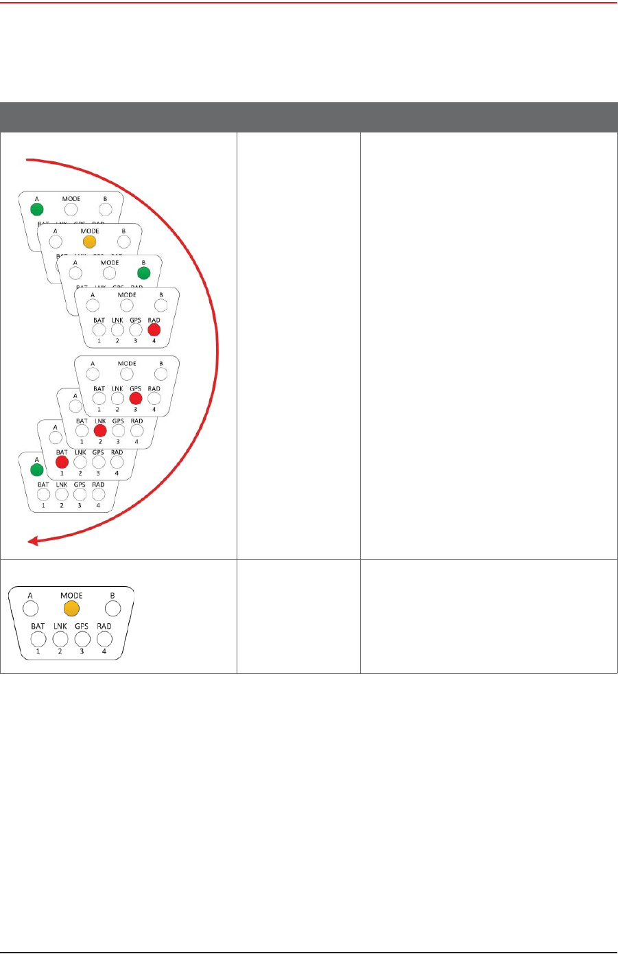
This chapter provides the possible LED status and error indicators for WRUs and LIUs.
The WRU has three possible states; undeployed, deploying, and deployed.
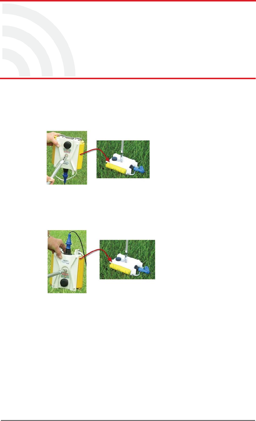
When tilting the WRU to deploy, re-acquire GPS, or check status, tilt the WRU geophone
down until the LEDs light, and then return the WRU to the horizontal position as shown
in the following figure:
When tilting the WRU to undeploy, tilt the WRU geophone up until the LEDs light, and
then return the WRU to the horizontal position as shown in the following figure:
D.1 WRU Undeployed
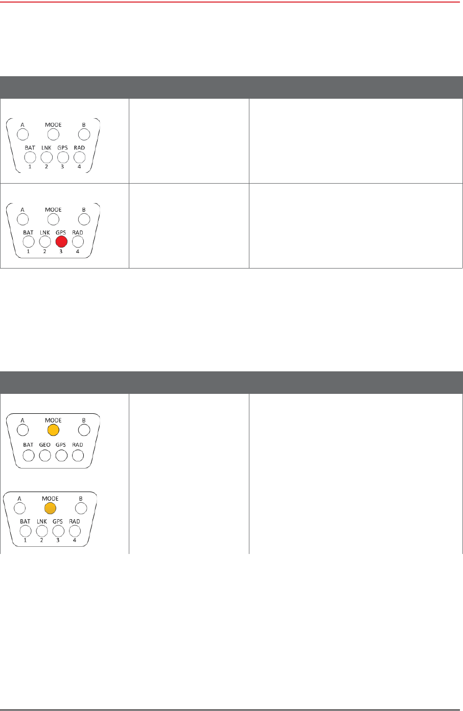
When the WRU is undeployed, all of the LEDs are off. A vertical tilt has the following
effect:
iGeophone Down – WRU deployment
iGeophone Up – No effect; nothing happens
Figure D–1 WRU Down-Tilt Action
Figure D–2 WRU Up-Tilt Action

164 RT System 2 v2.3 Deployment Guide R01.i
© 2010-2014 Wireless Seismic, Inc. All rights reserved.
D. LED Indicators
WRU Undeployed
After removing both batteries from an undeployed WRU, and then replacing BAT A, BAT B, or
both, when the first battery is connected, the WRU goes through the power on LED sequence
and then remains in the undeployed state.
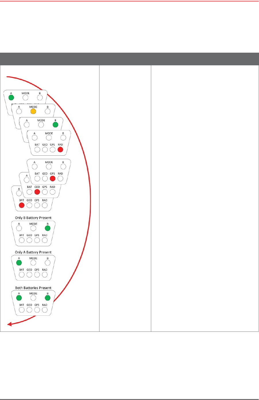
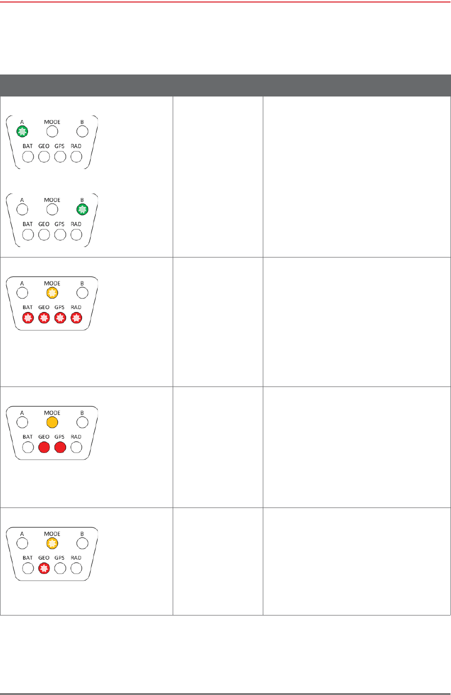
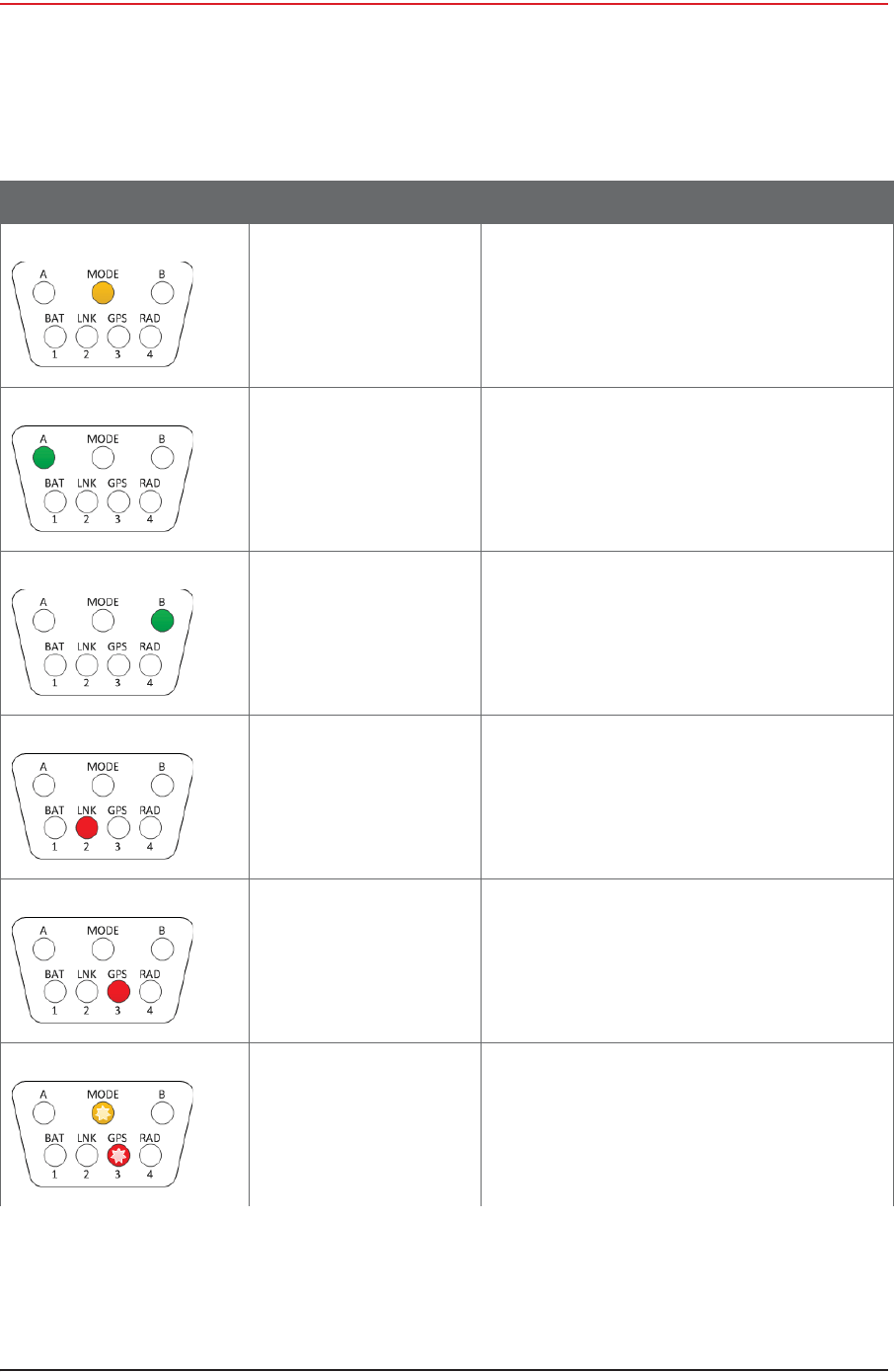
The following table shows the LED power-on sequence for an undeployed WRU:
Table D–1 WRU LED Indications, Undeployed
LED Indicators Summary Description
Undeployed
Dead batteries If no LEDs are on (lit up) on an undeployed
WRU, it can be one of the following scenarios:
• Unit undeployed
• Batteries dead
When you do a tilt test (geophone down) on
an undeployed WRU with no LEDs on, the
following may occur:
• An Undeployed WRU deploys and begins
the self tests
• A WRU with dead batteries will continue
to display no lit LEDs
• A WRU is defective if no LEDs turn on
after battery replacement.
NOTE: Battery state is shown in the RT
System 2 user interface tables. For
example, the Ground Equipment
Table.
Geo down tilt
detected
Deploy
Tilt the WRU with the geophone pointing
down.
After a few seconds, all of the LEDs light up
solid.
Place the WRU flat on the ground to within
five seconds to begin the deployment
process:
• Battery fuse self-test
• Battery test
•THD test
• Geophone test
• GPS fix
•Radio test
R01.i RT System 2 v2.3 Deployment Guide 165
© 2010-2014 Wireless Seismic, Inc. All rights reserved.
D. LED Indicators
WRU Deploying
D.2 WRU Deploying
When the WRU begins deploying, the following tests are executed:
Table D–2 WRU LED Indications, Undeployed Power-On Sequence
LED Indicators Summary Description
Hard reset
(power on) The LEDs light up in clockwise rotation
starting with the A battery LED and ending
with the A battery LED, B battery LED, or
both.

166 RT System 2 v2.3 Deployment Guide R01.i
© 2010-2014 Wireless Seismic, Inc. All rights reserved.
D. LED Indicators
WRU Deploying
iBAT A and BAT B connected
ƔBattery fuse test
ƔBattery test
ƔTHD test
ƔGeophone Test
ƔGPS test
ƔRadio Test
iBAT A or BAT B connected
ƔBattery test
ƔTHD test
ƔGeophone Test
ƔGPS test
ƔRadio Test
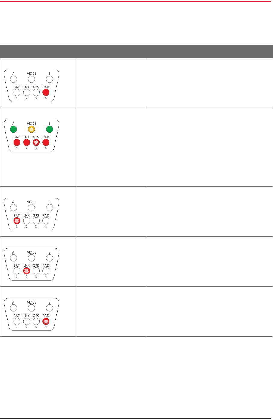
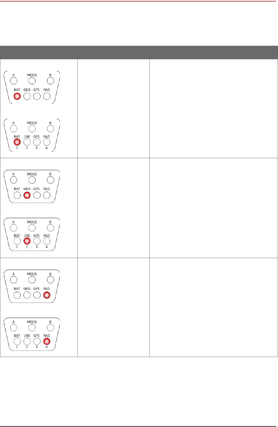
The following table shows the possible LED indicators for a WRU that is deploying:
Table D–3 WRU LED Indications, Deploying Sequence
LED Indicators Summary Description
Dead batteries
Defective Unit If no LEDs are on (lit up) during the deploying
state, it can be one of the following scenarios:
• Batteries dead
•Defective Unit
When you do a tilt test (geophone down) on a
WRU with no LEDs on, the following may
occur:
• A WRU with dead batteries will continue
to display no lit LEDs
• A WRU is defective if no LEDs turn on
after battery replacement.
NOTE: Battery state is shown in the RT
System 2 user interface tables. For
example, the Ground Equipment
Table.
A is solid for 5 seconds
BAT remains solid
Battery fuse test
failure (A) When both batteries are installed, the battery
fuse test is performed.
A Solid for 5 seconds
BAT Solid
A solid BAT LED indicates that the WRU
detected a bad fuse during deployment and
returned to the undeployed state. When a
battery fuse test fails, the WRU will not
deploy.
Both batteries must be present for the battery
fuse test to execute. This allows you to deploy
a WRU by removing the battery connected to
the bad fuse prior to the deployment tilt
action.

R01.i RT System 2 v2.3 Deployment Guide 167
© 2010-2014 Wireless Seismic, Inc. All rights reserved.
D. LED Indicators
WRU Deploying
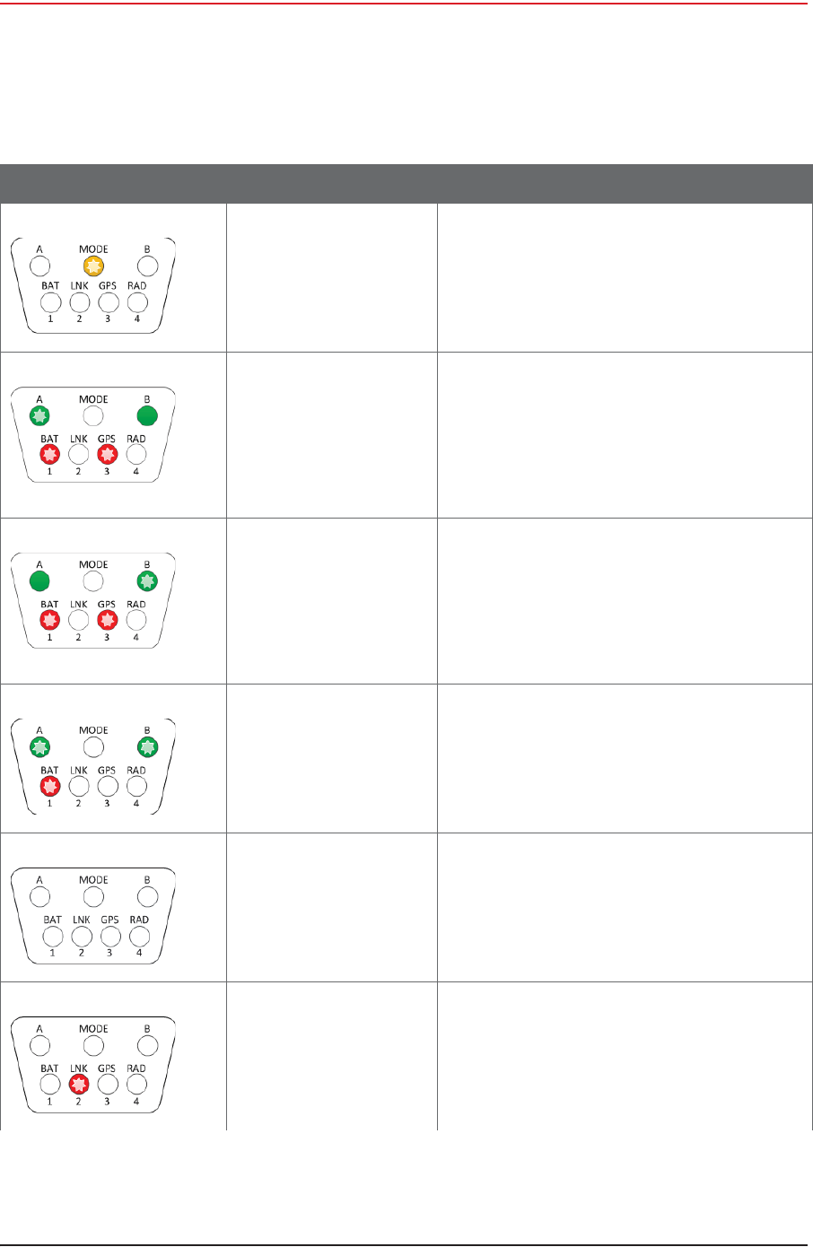
B is solid for 5 seconds
BAT remains solid
Battery fuse test
failure (B) When both batteries are installed, the battery
fuse test is performed.
B Solid for 5 seconds
BAT Solid
A solid BAT LED indicates that the WRU
detected a bad fuse during deployment and
returned to the undeployed state. When a
battery fuse test fails, the WRU will not
deploy.
Both batteries must be present for the battery
fuse test to execute. This allows you to deploy
a WRU by removing the battery connected to
the bad fuse prior to the deployment tilt
action.
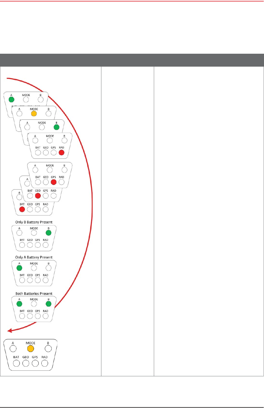
Battery test If both batteries are installed and their
capacities are above 9000 mAh, the following
occurs:
• Battery in use LED (A or B) Flashes
• The THD, GEO, GPS, and RAD self-tests
are performed
NOTE: The general battery test provides a
visual indication if the WRU has one
or more missing, malfunctioning, or
low capacity batteries and provides
45 seconds to correct the problem
before proceeding to the remainder
of the deployment self-tests.
Battery failure If one or both batteries have sub-9000mAh
capacities or are not installed, the following
occurs:
•Solid – A and or B
• Flashing – BAT LED flashes for 45
seconds
Install one or two batteries with capacities
above 9000 mAh during the 45 second
window. The following occurs:
• Flashing BAT LED turns off
• Battery in use LED (A or B) flashes for
approximately 2 seconds
• The THD, GEO, GPS, and RAD self-tests
are performed
Table D–3 WRU LED Indications, Deploying Sequence (cont.)
LED Indicators Summary Description
168 RT System 2 v2.3 Deployment Guide R01.i
© 2010-2014 Wireless Seismic, Inc. All rights reserved.
D. LED Indicators
WRU Deploying
If no changes are made to the batteries
within the 45 second window, The following
occurs:
• Flashing BAT LED turns off
• Battery in use LED (A or B) flashes for
approximately 2 seconds
• The THD, GEO, GPS, and RAD self-tests
are executed
Self-test starting If a WRU self-test fails, the WRU will continue
to the next test.
Flashing:
•MODE
•BAT
•GEO
•GPS
•RAD
NOTE: Error LEDs remain persistent
throughout the self-discovery process
and are turned off upon completion.
Continue (lay flat to
move to next test) To skip a test during the self-test process, tilt
the WRU geophone down until you see this
triangle of LEDs. Tilt the WRU back to
horizontal to continue.
Solid:
•MODE
•GEO
•GPS
NOTE: The GPS test cannot be skipped.
Geophone test in
progress Flashing:
•MODE
•GEO
NOTE: Performing a vertical geophone down
tilt during the geophone test causes
the WRU to go into the
communications repeater mode.
WRU repeaters are used to solve
terrain or distance related
communication problems between
WRUs.
Table D–3 WRU LED Indications, Deploying Sequence (cont.)
LED Indicators Summary Description
R01.i RT System 2 v2.3 Deployment Guide 169
© 2010-2014 Wireless Seismic, Inc. All rights reserved.
D. LED Indicators
WRU Deploying
THD test failure Solid:
•BAT
•GEO
•GPS
•RAD
NOTE: No LEDs are affected when the THD
test starts or when it passes.
Geophone test
failure GEO Solid
NOTE: For a multiple-channel geophone,
tests the first channel only.
Acquiring GPS fix Flashing:
•MODE
•GPS
NOTE: The WRU will attempt to get a 3-
meter GPS lock for up to 15 minutes.
During this time, the GPS LED
flashes. The WRU will not form until
the GPS lock is achieved. If the GPS
lock cannot be achieved, form by
serial number.
GPS test failure GPS Solid
GPS fix not found
For a multiple-channel geophone, tests the
first channel only.
Neighbor discovery
in progress Flashing:
•MODE
•RAD
Neighbor discovered Flashing:
•A
•MODE
•B
Table D–3 WRU LED Indications, Deploying Sequence (cont.)
LED Indicators Summary Description

170 RT System 2 v2.3 Deployment Guide R01.i
© 2010-2014 Wireless Seismic, Inc. All rights reserved.
D. LED Indicators
WRU Deploying
If power is removed from a WRU in the deploying state, the WRU stays in the deploying state
and restarts the deploying process when power is restored.
After removing both batteries from a deploying WRU, and then replacing BAT A, BAT B, or
both, when the first battery is connected, the WRU goes through the power on LED
sequence. If both batteries are connected, the battery fuse test is executed. If only one
battery is connected, the battery fuse test is skipped. The remainder of the self-tests are
then executed.
The following table shows the LED power-on sequence for an deploying WRU:
No neighbor
detected RAD Solid
If this is the first WRU deployed, this is the
expected condition.
Table D–3 WRU LED Indications, Deploying Sequence (cont.)
LED Indicators Summary Description
R01.i RT System 2 v2.3 Deployment Guide 171
© 2010-2014 Wireless Seismic, Inc. All rights reserved.
D. LED Indicators
WRU Deploying
Table D–4 WRU LED Indications, Deploying Power-On Sequence
LED Indicators Summary Description
Hard reset
(power on) The LEDs light up in clockwise rotation
starting with the A battery LED and ending
with the A battery LED, B battery LED, or
both for 2 seconds.
The A and B battery LEDs at the end of the
rotation indicate that one or both batteries
are above the minimum threshold of
9000mAh.
Finally, the MODE LED lights up for
approximately 5 seconds indicating that the
WRU is verifying its firmware integrity.

172 RT System 2 v2.3 Deployment Guide R01.i
© 2010-2014 Wireless Seismic, Inc. All rights reserved.
D. LED Indicators
WRU Deployed
D.3 WRU Deployed
If the WRU is already deployed, a vertical tilt has the following effect:
iGeophone Down – If Sleeping, takes three to four seconds to wake up. If in Standby or
Armed displays the battery status, deployment self-test status, and re-acquires the GPS
position.
iGeophone Up – All lights light. If placed flat within 5 seconds, the WRU undeploys.
The following table shows how the LEDs light up during normal operation with no vertical tilt
for a deployed WRU.
The following table shows how the LEDs light up during a vertical tilt (geophone down) for a
deployed WRU.
Table D–5 WRU LED Indications, Deployed WRU, No Geophone Tilt
LED Indicators Summary Description
Undeployed
Dead Batteries
Sleeping
If no LEDs are on (lit up), it can be one of the
following scenarios:
• WRU undeployed
• Batteries dead
•WRU Sleeping
• WRU Awake, but unformed
NOTE: Battery state is shown in the RT
System 2 user interface tables. For
example, the Ground Equipment
Table.
Battery A in use A Flashing:
• Battery A in use
• WRU formed or Armed
Battery B in use B Flashing:
• Battery B in use
• WRU formed or Armed

R01.i RT System 2 v2.3 Deployment Guide 173
© 2010-2014 Wireless Seismic, Inc. All rights reserved.
D. LED Indicators
WRU Deployed
Table D–6 WRU LED Indications, Deployed WRU, Geophone Down Tilt
LED Indicators Summary Description
Undeployed
Dead Batteries
Sleeping
If no LEDs are on (lit up) before tilting the
WRU, it can be one of the following scenarios:
• WRU undeployed
• Batteries dead
•WRU Sleeping
• WRU Awake, but unformed
When you do a tilt test (geophone down) on a
WRU with no LEDs on, the following may
occur:
• An Undeployed WRU deploys and begins
the self tests
• A WRU with dead batteries will continue
to display no lit LEDs
• A Sleeping WRU goes back to the
deployed, unformed state and displays
the battery status and any self-tests that
failed during deployment (BAT, THD, GEO,
GPS, or RAD).
• A WRU in the Awake unformed state
displays the battery status and any self-
tests that failed during deployment (BAT,
THD, GEO,GPS, or RAD).
NOTE: Battery state is shown in the
RT System 2 user interface tables.
For example, the Ground Equipment
Table.
Battery A in use A Flashing:
• Battery A in use
• WRU formed or Armed
NOTE: Only when GPS position occurs at the
same time the battery status is
displayed.
Battery B in use B Flashing:
• Battery B in use
• WRU formed or Armed
NOTE: Only when no self-test failures. Re-
acquire GPS position occurs at the
same time the battery status is
displayed.
174 RT System 2 v2.3 Deployment Guide R01.i
© 2010-2014 Wireless Seismic, Inc. All rights reserved.
D. LED Indicators
WRU Deployed
The following table shows how the LEDs light up during a vertical tilt (geophone up) for a
deployed WRU.
Re-acquire GPS
position GPS Solid for up to 15 minutes
The deployed WRU can be in any of the
following states:
•Unformed
•Formed
NOTE: The battery status is displayed at the
same time the GPS position is re-
acquiring.
GPS position
acquired GPS Flashing
The Deployed WRU is in Standby
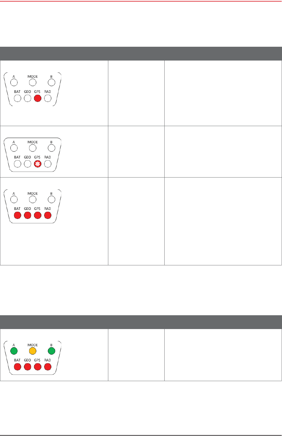
Self test failure The LED associated with the failed self-test is
solid. All four LEDs are solid only if all four
self-tests failed, or the THD self-test fails.
The LEDs are visible only during the
deployment process, and when the WRU is
tilted (geophone down) to check status after
the WRU is deployed.
Solid:
•BAT
•GEO
•GPS
•RAD
Table D–6 WRU LED Indications, Deployed WRU, Geophone Down Tilt (cont.)
LED Indicators Summary Description
Table D–7 WRU LED Indications, Deployed WRU, Geophone Up Tilt
LED Indicators Summary Description
Geo tilt detected
Undeploy Tilt the WRU with the geophone pointing up.
After a few seconds, all of the LEDs light up
solid.
Place the WRU flat on the ground within five
seconds to undeploy the WRU.

R01.i RT System 2 v2.3 Deployment Guide 175
© 2010-2014 Wireless Seismic, Inc. All rights reserved.
D. LED Indicators
LIU Power-On
After removing both batteries from a deployed WRU, and then replacing BAT A, BAT B, or
both, when the first battery is connected, the WRU goes through the power on LED
sequence. The WRU transitions to the Awake, unformed state. If the WRU is not formed
within 30 minutes, the WRU transitions to the Sleep state.
D.4 LIU Power-On
The LIU LEDs function independently from each other, and there can be a number of
combinations of LEDs that are on, off, or flashing. The following list shows the LEDs used to
indicate status:
iBattery – A, B, BAT
iPower, Mode – MODE
iDiscipline – MODE
iCheck Link Status – MODE, 1, 2, 3, and 4
iConnection to Central – LNK
iGPS Lock – GPS
iRadio connection, communication with neighbor – RAD
The following table shows the LED power-on sequence for an LIU:
Undeploy successful Flashing:
•A
•MODE
•B
Table D–7 WRU LED Indications, Deployed WRU, Geophone Up Tilt (cont.)
LED Indicators Summary Description
Table D–8 LIU LED Indications, Power-On Sequence
LED Indicators Summary Description
Off No lights
176 RT System 2 v2.3 Deployment Guide R01.i
© 2010-2014 Wireless Seismic, Inc. All rights reserved.
D. LED Indicators
LIU Normal Operation
D.5 LIU Normal Operation
The following tables describe the possible Normal Mode LIU Status Indications:
i“LIU LED Status Indications, Normal Mode” on page 177
i“LIU LED Error Indications, Normal Mode” on page 179
Hard Reset LIU The LEDs light up in clockwise rotation
starting and ending with the A battery LED in
the following cases:
• When the batteries are attached
• Anytime the unit resets itself
• In between updating firmware
applications
The unit is verifying
the integrity of the
firmware.
MODE Solid for approximately 5 seconds
Table D–8 LIU LED Indications, Power-On Sequence (cont.)
LED Indicators Summary Description
R01.i RT System 2 v2.3 Deployment Guide 177
© 2010-2014 Wireless Seismic, Inc. All rights reserved.
D. LED Indicators
LIU Normal Operation
Table D–9 LIU LED Status Indications, Normal Mode
LED Indicators Summary Description
On, Disciplined to GPS
Checking firmware
MODE solid
The MODE LED indicates that the integrity of the
downloaded firmware is being verified.
Battery A in use A solid
Indicates Battery A in use powering LIU. Battery
Voltage is above depleted threshold.
Battery B in use B solid
Indicates Battery B in use powering LIU. Battery
Voltage is above depleted threshold.
LIU connected to Central LNK solid
GPS lock GPS solid
GPS disciplined Flashing:
• GPS flashes in the 1 s rhythm of the PPS
• MODE flashes in the 1 s rhythm of the PPS
178 RT System 2 v2.3 Deployment Guide R01.i
© 2010-2014 Wireless Seismic, Inc. All rights reserved.
D. LED Indicators
LIU Normal Operation
Formed RAD solid
Normal Solid:
•A/B
•BAT
• LNK (connected)
•RAD (formed)
Flashing:
•MODE
•GPS
• LNK (disconnected)
Main (ARM) processor is
upgrading its own firmware BAT flashing
Main (ARM) processor is
upgrading the Power
Control (XMEGA) processor
firmware
LNK flashing
Main (ARM) processor is
upgrading the Radio
processor firmware
RAD flashing
Table D–9 LIU LED Status Indications, Normal Mode (cont.)
LED Indicators Summary Description
R01.i RT System 2 v2.3 Deployment Guide 179
© 2010-2014 Wireless Seismic, Inc. All rights reserved.
D. LED Indicators
LIU Normal Operation
Table D–10 LIU LED Error Indications, Normal Mode
LED Indicators Summary Description
On, no GPS discipline MODE flashing every 1 second
Single battery failure
Battery B in use
Battery A below threshold
or disconnected
A:
•Off, or
• 4 long flashes, then off (On 4.5s, off 2s) or
• GPS PPS flash
B Solid
BAT:
• 4 long flashes, then off (On 4.5s, off 2s)
Single battery failure
Battery A in use
Battery B below threshold
or disconnected
A Solid
B:
•Off, or
• 4 long flashes, then off (On 4.5s, off 2s) or
• GPS PPS flash
BAT:
• 4 long flashes, then off (On 4.5s, off 2s)
Both batteries below
threshold
–OR–
One below threshold and
one disconnected
A & B:
•Off, or
• 4 long flashes, then off (On 4.5s, off 2s) or
• GPS PPS flashes
BAT:
• 4 long flashes, then off (On 4.5s, off 2s)
No IP Address acquired LNK off
LIU has IP Address, but no
communications with
Central
LNK flashing
180 RT System 2 v2.3 Deployment Guide R01.i
© 2010-2014 Wireless Seismic, Inc. All rights reserved.
D. LED Indicators
Firmware Upgrade
D.6 Firmware Upgrade
The following table describes the possible WRU and LIU LED indications during firmware
upgrade:
No GPS lock GPS off
No GPS or less than 3 satellites
GPS lock, not disciplined GPS on
GPS lock, but not disciplined
Table D–10 LIU LED Error Indications, Normal Mode (cont.)
LED Indicators Summary Description
Table D–11 WRU and LIU LED Status Indications, Firmware Upgrade
LED Indicators Summary Description
Firmware upgrade MODE Solid for approximately 5 seconds
During firmware upgrade, the MODE LED indicates
that each processor's new firmware is being
verified.
R01.i RT System 2 v2.3 Deployment Guide 181
© 2010-2014 Wireless Seismic, Inc. All rights reserved.
D. LED Indicators
Firmware Upgrade
Firmware upgrade BAT Flashing
The main processor is saving the new firmware for
all processors to non-volatile memory.
The power control
processor's firmware is
being upgraded
GEO/LNK Flashing for approximately 15 seconds
The Radio processor's
firmware is being upgraded RAD Flashing for approximately 1-2 seconds
Table D–11 WRU and LIU LED Status Indications, Firmware Upgrade (cont.)
LED Indicators Summary Description
RT System 2 v2.3 182 Deployment Guide R01.i
© 2010-2014 Wireless Seismic, Inc. All rights reserved.
E
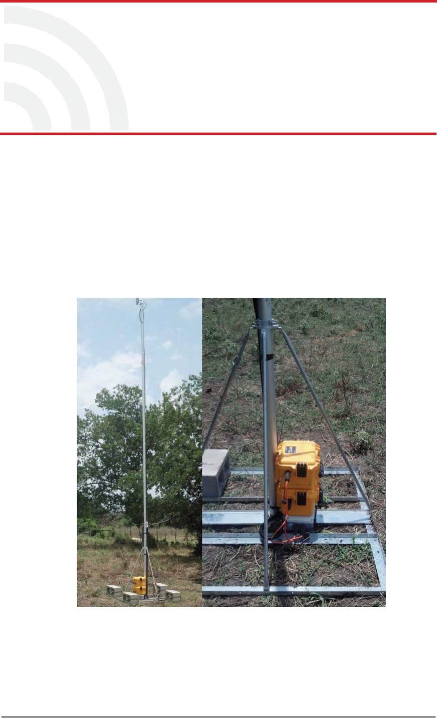
E. Weighted Base
This section describes the mast that uses weights to maintain stability.
E.1 Specifications
Tripod Weight = 50 lbs (22.73 kg)
Minimum mast height = 53” (includes 6” for mounting)
Base size = 48” (1.2m) x 48” (1.2m)
Supports up to 12 – 16” x 8” blocks
Pre-galvanized steel frame
Accepts up to 2.5” mast (not included)
Figure E–1 Weighted Mast
R01.i RT System 2 v2.3 Deployment Guide 183
© 2010-2014 Wireless Seismic, Inc. All rights reserved.
E. Weighted Base
Hardware Supplied
E.2 Hardware Supplied
The following hardware is supplied with the tripod mast:
i4 - Bolt, Carriage 1/4 - 20 x 3/4"
i12 - Bolt, Carriage 1/4 - 20 x 5/8"
i4 - Bolt, 1/4 - 20 x 3/4" Hex Head
i4- Bolt, 1/4 - 20 x 1/2" Hex Head
i24-Nut, 1/4 - 20
i24 - Lock washer, 1/4 Int. tooth
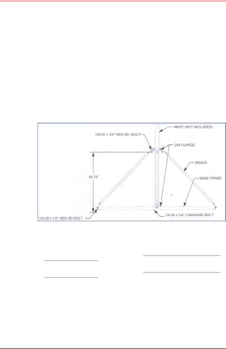
E.3 Assembly Instructions
This section provides instructions and illustrations for assembly of the tripod.
To assemble the tripod:
1Assemble one 244 Flange to the Center Support Plate using four 1/4-20 x 3/4" carriage
Bolts, Lock washers and Hex Nuts. Make sure to assemble the Bolts with the Heads on
the underside of the frame. Hex Nut should be on the top side of the frame.
2 Assemble Base Frame and Center Support Plate using twelve 1/4-20 x 5/8" carriage
Bolts, Lock washers and Hex Nuts. Make sure to assemble the Bolts with the Heads on
the underside of the frame. Hex Nut should be on the top side of the frame.
3Assemble the four (4) Braces to the upper support flange using four 1/4-20x3/4 Hex
Head Bolts, Lock washers and Nuts.
4Assemble the other end of the braces to the base frame using the four (4) 1/4-20 x 1/2"
Hex Head Bolts, Lock washers, and Nuts.
5Insert Bolts into upper and lower flange.
6Slide the mast (not included) into position and tighten securely and weigh.
Wade Antenna Ltd., Ontario, Canada
Figure E–2 Tripod Assembly, Front View
RT System 2 v2.3 184 Deployment Guide R01.i
© 2010-2014 Wireless Seismic, Inc. All rights reserved.
F
F. Using a Compass
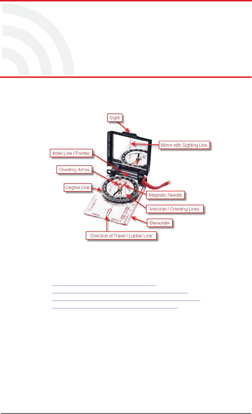
This chapter describes how to use a sighting compass. A sighting compass has the same
features as a baseplate compass, but adds a vertical mirror that allows you to view the
compass dial and the landmark at the same time.
For a in-depth descriptions of using a compass with a map and setting the declination on
a compass see the following links:
ihttp://www.compassdude.com/default.shtml
ihttp://www.compassdude.com/compass-declination.shtml
ihttp://www.rei.com/learn/expert-advice/navigation-basics.html
ihttp://www.thecompassstore.com/howtouseyour.html
A compass needle points to the magnetic north pole which is not the same as true or
geographic north. The difference between magnetic and true north is called magnetic
declination. The declination value depends on your actual location on the Earth. Over
time, as the Earth’s magnetic field shifts, the declination values also shift.
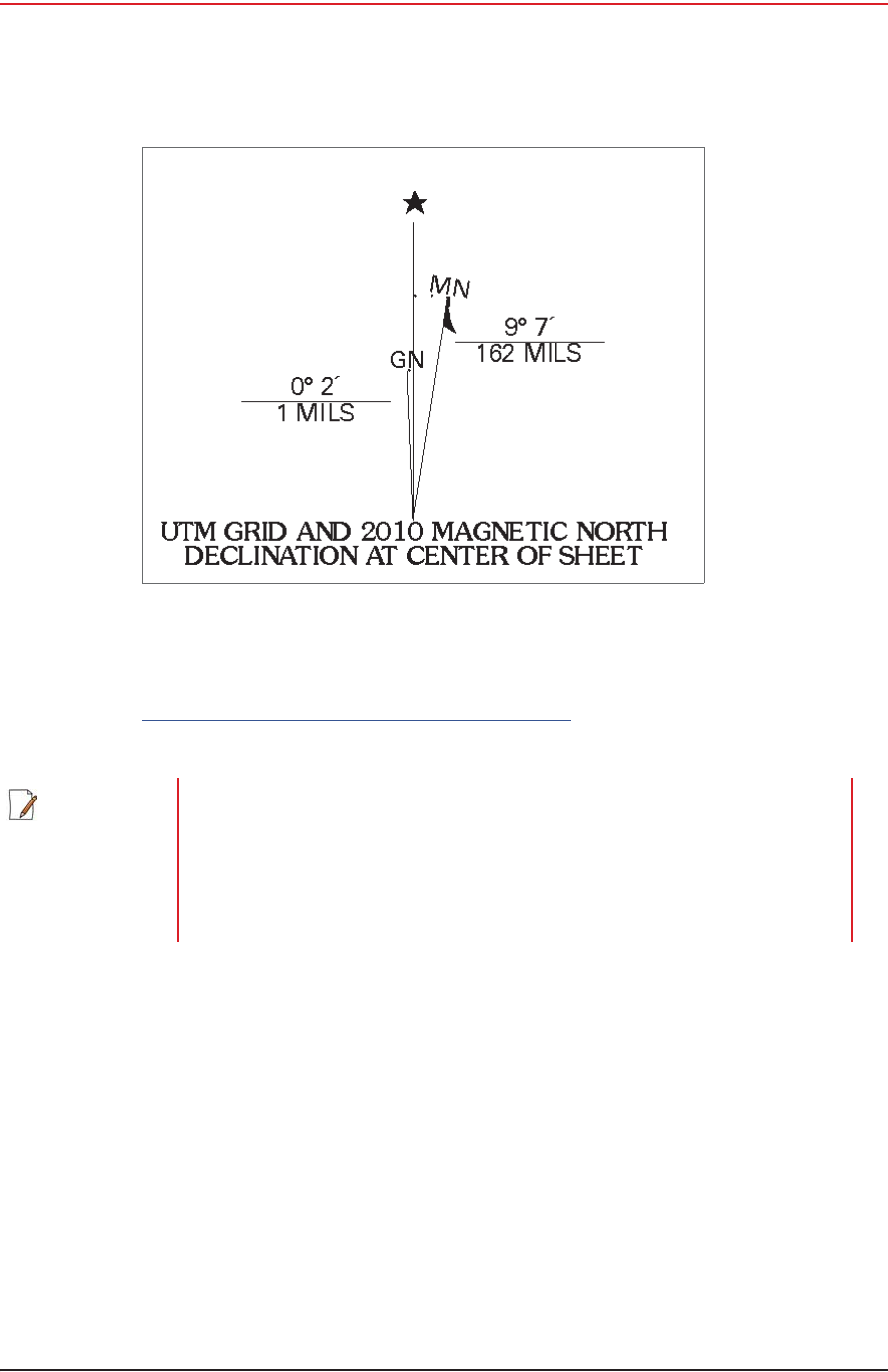
Maps are drawn with true north at the top edge. When using a compass to navigate or
locate objects, you must adjust the readings to account for the angular difference
between true north ( ღ) and magnetic north (MN). The declination value is marked on
topographical maps as shown in the following figure:
Figure F–1 Sighting Compass (70-0067)
R01.i RT System 2 v2.3 Deployment Guide 185
© 2010-2014 Wireless Seismic, Inc. All rights reserved.
F. Using a Compass
However, because of the dynamic nature of the Earth’s magnetic field, old maps are
inaccurate. To obtain the most recent declination values, enter your map location at the
following link:
http://www.ngdc.noaa.gov/geomag-web/#declination
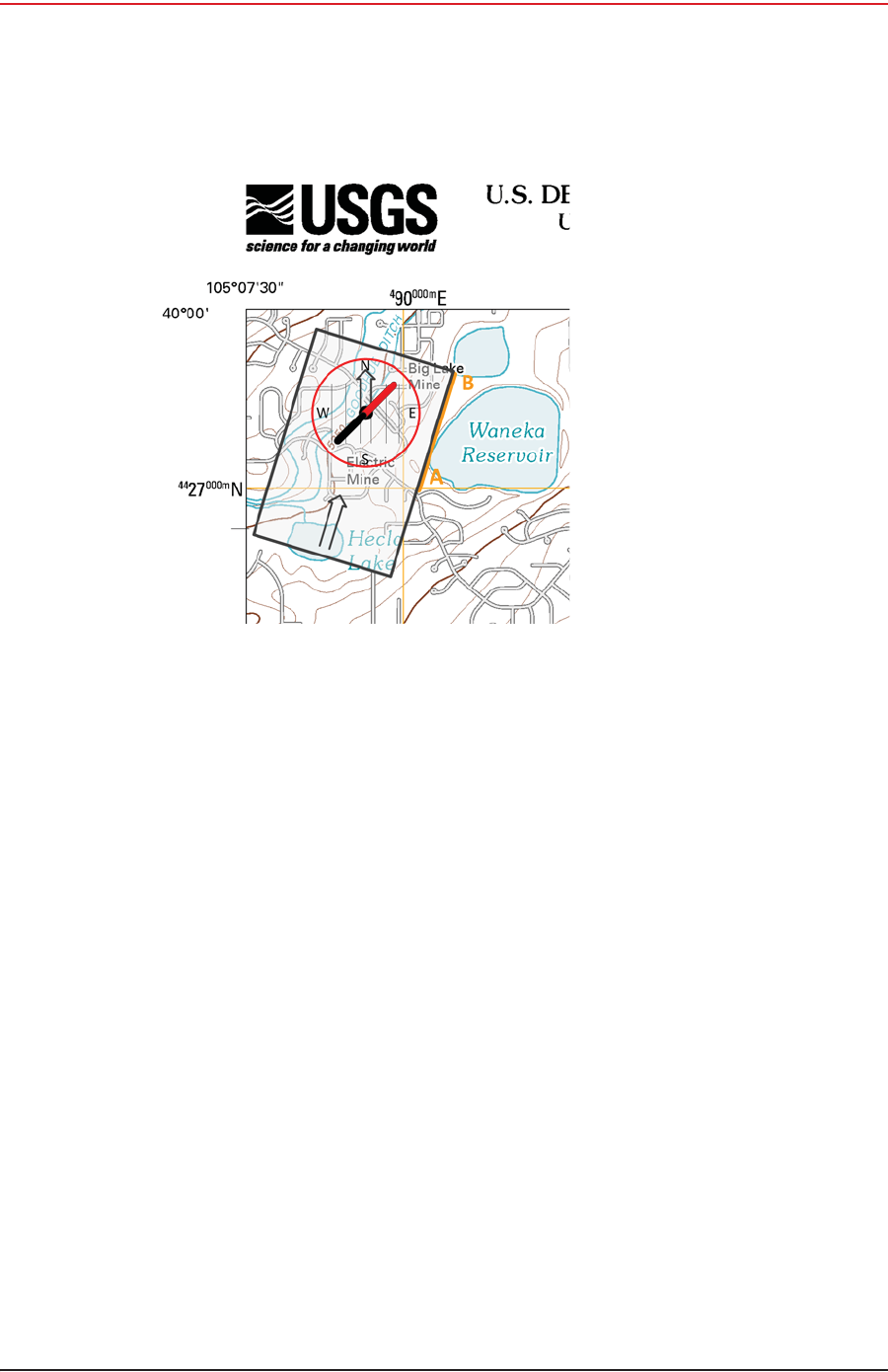
To locate an object using a map and a compass:
1Place the long edge of the compass baseplate on the map, connecting the desired start
and end points. For example, the start point could be where you are standing [A], and
the end point [B] is where you want to locate the backhaul mast. The Direction of Travel
arrow should point towards the end point (mast location).
2While holding the compass on the map, turn the Degree Dial until the Meridian /
Orienting Lines are parallel with the Meridian lines on the map. This is the same as
turning the Degree Dial until the Orienting Arrow points to north on the map.
Figure F–2 Declination Indication on Map
NOTE Placing magnetic objects near a compass can cause an incorrect reading
(deviation). Examples include:
• Objects that contain steel and iron such as pocket knives, belt buckles,
vehicles, railroad tracks, and ore deposits in the Earth
• Objects that use magnets such as stereo speakers
• Electrical current in cables and overhead lines
186 RT System 2 v2.3 Deployment Guide R01.i
© 2010-2014 Wireless Seismic, Inc. All rights reserved.
F. Using a Compass
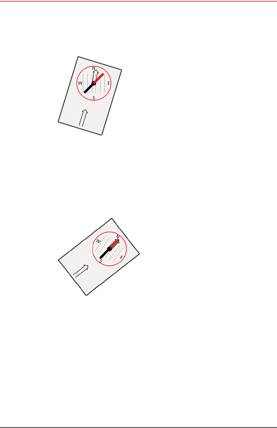
3Adjust for declination.
ƔIf you have an adjustable compass – Move the Orienting Arrow to the right or left by
the declination number. When you align the magnetic needle with the Orienting
Arrow, the declination is accounted for.
ƔIf you do not have an adjustable compass – Mark the declination on your compass
with a piece of tape. Align the magnetic needle with the tape mark.
ƔAdjust the Orienting Arrow to the left or right. For example:
ŹFor a declination of 0, no adjustment is necessary.
ŹFor a declination of 9 (9 degrees East), move the Orienting Arrow (or place a
tape mark) to the right 9 degrees.
ŹFor a declination of -9 (9 degrees West), move the Orienting Arrow (or place a
tape mark) to the left 9 degrees.
Figure F–3 Compass and Map
R01.i RT System 2 v2.3 Deployment Guide 187
© 2010-2014 Wireless Seismic, Inc. All rights reserved.
F. Using a Compass
4Pick up the compass and adjust the cover so the angle of the cover to the base is
between 45 and 70 degrees.
5Hold the base of the compass in the palm of your hand. Keep the compass level. Turn
your entire body and the compass until the red end of the Magnetic Needle is aligned
with the red end (north end) of Orienting Arrow.
6While holding the compass at eye level, keep the compass level and align your
destination with the sight notch on the top of the case.
7Ensure that the sighting line in the mirror passes through the center of the compass
wheel.
Figure F–4 Compass Adjusted for
Declination
Figure F–5 Compass Adjusted for
Declination
RT System 2 v2.3 188 Deployment Guide R01.i
© 2010-2014 Wireless Seismic, Inc. All rights reserved.
G
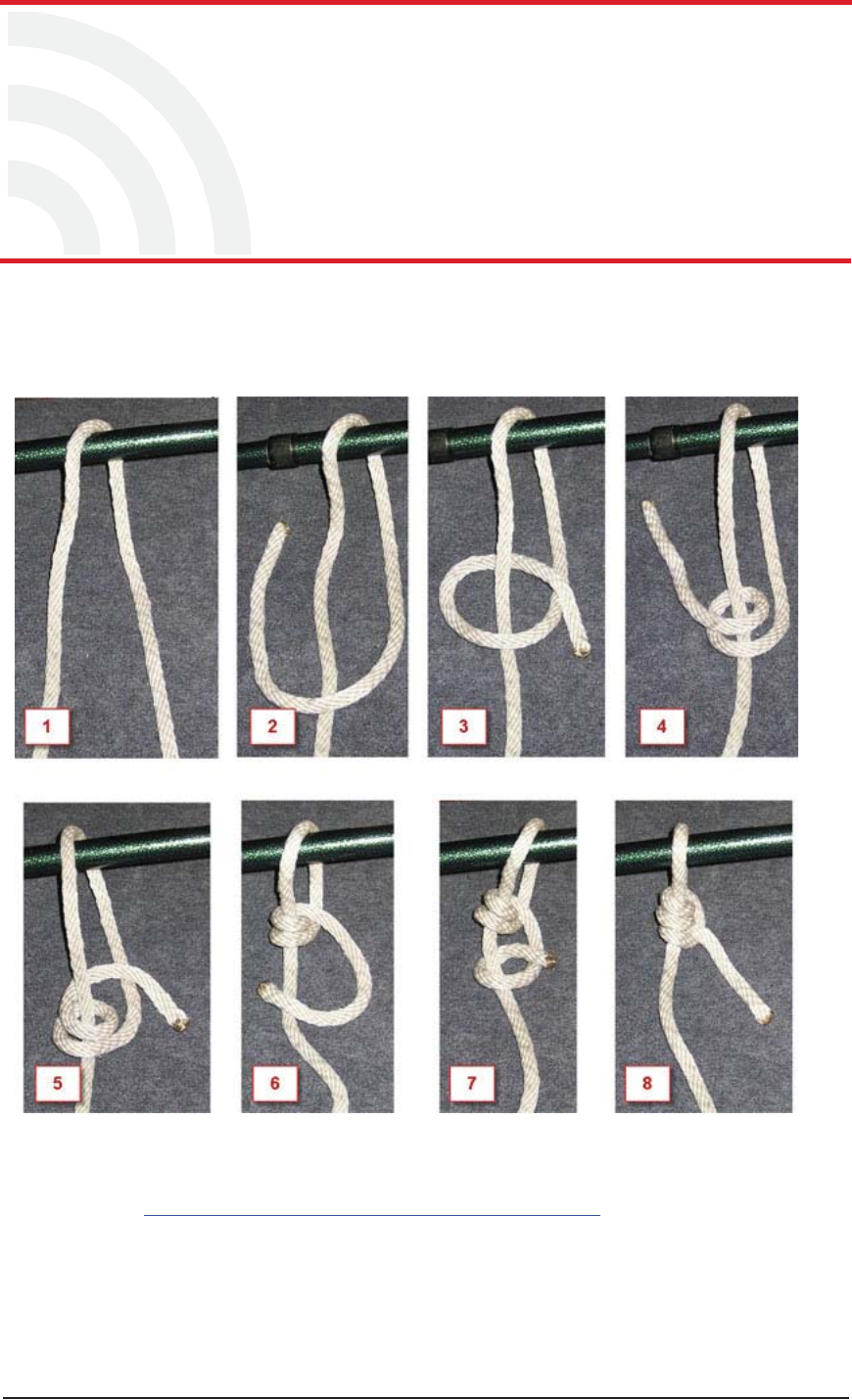
G. Rope Knot
This chapter shows how to tie a taut-line hitch knot. This loop knot can be adjusted to
loosen or tighten a line, yet holds under a load. This knot is commonly used to secure
tent lines and loads on vehicles. It is the recommended knot for securing the RT System
2 guy rope mast.
The following link provides a short video example:
http://www.sailingcourse.com/videos/taut_line_hitch.htm
Figure G–1 Tying the Taut-line Hitch Knot

RT System 2 v2.3 189 Deployment Guide R01.i
© 2010-2014 Wireless Seismic, Inc. All rights reserved.
H
H. Country Codes
This chapter provides a quick-reference to the ISO
3166 country codes.
Table H–1 ISO 3166 Country Codes
Name Code
Afghanistan 004
Åland Islands 248
Albania 008
Algeria 012
American Samoa 016
Andorra 020
Angola 024
Anguilla 660
Antarctica 010
Antigua and Barbuda 028
Argentina 032
Armenia 051
Aruba 533
Australia 036
Austria 040
Azerbaijan 031
Bahamas (the) 044
Bahrain 048
Bangladesh 050
Barbados 052
Belarus 112
Belgium 056
Belize 084
Benin 204
Bermuda 060
Bhutan 064
Bolivia, Plurinational
State of 068
Bonaire, Sint Eustatius
and Saba 535
Bosnia and Herzegovina 070
Botswana 072
Bouvet Island 074
Brazil 076
British Indian Ocean
Territory (the) 086
Brunei Darussalam 096
Bulgaria 100
Burkina Faso 854
Burundi 108
Cambodia 116
Cameroon 120
Canada 124
Cape Verde 132
Cayman Islands (the) 136
Central African Republic
(the) 140
Chad 148
Chile 152
China 156
Christmas Island 162
Cocos (Keeling) Islands
(the) 166
Colombia 170
Comoros 174
Congo 178
Table H–1 ISO 3166 Country Codes
Name Code

H. Country Codes
190 RT System 2 v2.3 Deployment Guide R01.i
© 2010-2014 Wireless Seismic, Inc. All rights reserved.
Congo (the Democratic
Republic of the) 180
Cook Islands (the) 184
Costa Rica 188
Côte d'Ivoire 384
Croatia 191
Cuba 192
Curaçao 531
Cyprus 196
Czech Republic (the) 203
Denmark 208
Djibouti 262
Dominica 212
Dominican Republic (the) 214
Ecuador 218
Egypt 818
El Salvador 222
Equatorial Guinea 226
Eritrea 232
Estonia 233
Ethiopia 231
Falkland Islands (the)
[Malvinas] 238
Faroe Islands (the) 234
Fiji 242
Finland 246
France 250
French Guiana 254
French Polynesia 258
French Southern
Territories (the) 260
Gabon 266
Gambia (The) 270
Table H–1 ISO 3166 Country Codes
Name Code
Georgia 268
Germany 276
Ghana 288
Gibraltar 292
Greece 300
Greenland 304
Grenada 308
Guadeloupe 312
Guam 316
Guatemala 320
Guernsey 831
Guinea 324
Guinea-Bissau 624
Guyana 328
Haiti 332
Heard Island and
McDonald Islands 334
Holy See (the) [Vatican
City State] 336
Honduras 340
Hong Kong 344
Hungary 348
Iceland 352
India 356
Indonesia 360
Iran (the Islamic
Republic of) 364
Iraq 368
Ireland 372
Isle of Man 833
Israel 376
Italy 380
Jamaica 388
Table H–1 ISO 3166 Country Codes
Name Code

H. Country Codes
R01.i RT System 2 v2.3 Deployment Guide 191
© 2010-2014 Wireless Seismic, Inc. All rights reserved.
Japan 392
Jersey 832
Jordan 400
Kazakhstan 398
Kenya 404
Kiribati 296
Korea (the Democratic
People's Republic of) 408
Korea (the Republic of) 410
Kuwait 414
Kyrgyzstan 417
Lao People's Democratic
Republic (the) 418
Latvia 428
Lebanon 422
Lesotho 426
Liberia 430
Libya 434
Liechtenstein 438
Lithuania 440
Luxembourg 442
Macao 446
Macedonia (the former
Yugoslav Republic of) 807
Madagascar 450
Malawi 454
Malaysia 458
Maldives 462
Mali 466
Malta 470
Marshall Islands (the) 584
Martinique 474
Mauritania 478
Table H–1 ISO 3166 Country Codes
Name Code
Mauritius 480
Mayotte 175
Mexico 484
Micronesia (the
Federated States of) 583
Moldova (the Republic
of) 498
Monaco 492
Mongolia 496
Montenegro 499
Montserrat 500
Morocco 504
Mozambique 508
Myanmar 104
Namibia 516
Nauru 520
Nepal 524
Netherlands (the) 528
New Caledonia 540
New Zealand 554
Nicaragua 558
Niger (the) 562
Nigeria 566
Niue 570
Norfolk Island 574
Northern Mariana Islands
(the) 580
Norway 578
Oman 512
Pakistan 586
Palau 585
Palestine, State of 275
Panama 591
Table H–1 ISO 3166 Country Codes
Name Code

H. Country Codes
192 RT System 2 v2.3 Deployment Guide R01.i
© 2010-2014 Wireless Seismic, Inc. All rights reserved.
Papua New Guinea 598
Paraguay 600
Peru 604
Philippines (the) 608
Pitcairn 612
Poland 616
Portugal 620
Puerto Rico 630
Qatar 634
Réunion 638
Romania 642
Russian Federation (the) 643
Rwanda 646
Saint Barthélemy 652
Saint Helena, Ascension
and Tristan da Cunha 654
Saint Kitts and Nevis 659
Saint Lucia 662
Saint Martin (French
part) 663
Saint Pierre and
Miquelon 666
Saint Vincent and the
Grenadines 670
Samoa 882
San Marino 674
Sao Tome and Principe 678
Saudi Arabia 682
Senegal 686
Serbia 688
Seychelles 690
Sierra Leone 694
Singapore 702
Table H–1 ISO 3166 Country Codes
Name Code
Sint Maarten (Dutch
part) 534
Slovakia 703
Slovenia 705
Solomon Islands (the) 090
Somalia 706
South Africa 710
South Georgia and the
South Sandwich Islands 239
South Sudan 728
Spain 724
Sri Lanka 144
Sudan (the) 729
Suriname 740
Svalbard and Jan Mayen 744
Swaziland 748
Sweden 752
Switzerland 756
Syrian Arab Republic
(the) 760
Taiwan (Province of
China) 158
Tajikistan 762
Tanzania, United
Republic of 834
Thailand 764
Timor-Leste 626
Togo 768
Tokelau 772
Tonga 776
Trinidad and Tobago 780
Tunisia 788
Turkey 792
Turkmenistan 795
Table H–1 ISO 3166 Country Codes
Name Code

H. Country Codes
R01.i RT System 2 v2.3 Deployment Guide 193
© 2010-2014 Wireless Seismic, Inc. All rights reserved.
Turks and Caicos Islands
(the) 796
Tuvalu 798
Uganda 800
Ukraine 804
United Arab Emirates
(the) 784
United Kingdom (the) 826
United States (the) 840
United States Minor
Outlying Islands (the) 581
Uruguay 858
Uzbekistan 860
Vanuatu 548
Venezuela, Bolivarian
Republic of 862
Viet Nam 704
Virgin Islands (British) 092
Virgin Islands (U.S.) 850
Wallis and Futuna 876
Western Sahara* 732
Yemen 887
Zambia 894
Zimbabwe 716
Table H–1 ISO 3166 Country Codes
Name Code

RT System 2 v2.3 194 Deployment Guide R01.i
© 2010-2014 Wireless Seismic, Inc. All rights reserved.
I
I. Français
Ce chapitre fournit des informations sur le suivant :
i“Batteries” sur la page 194
i“l'information juridique” sur la page 200
I.1 Batteries
Ce chapitre fournit des informations sur les batteries utilisées dans le système
RT System 2 de Wireless Seismic, Inc.
I.1.1 Batteries au lithium-ion
Cette section fournit des informations sur les caractéristiques, l'utilisation et la
manipulation des batteries au lithium-ion. Reportez-vous aux sections suivantes pour en
savoir plus:
Ɣ“Spécifications” on page 194
Ɣ“Directives en matière de manipulation et de sécurité” on page 195
Ɣ“Transport” on page 196
Ɣ“Entreposage” on page 198
I.1.1.1 Spécifications
Le RT System 2 utilise une ou deux batteries au lithium-ion intelligentes et
personnalisées, dotées d'un circuit de charge autonome qui protège les batteries contre
les surcharges, décharges, courts-circuits ou changements extrêmes de température.
Le tableau suivant indique les spécifications des batteries:
Tableau I–1 Spécifications des batteries au lithium-ion
Élément Description Valeur
Tension Nominale 3,7 V c.c.
Arrêt 2,8 V c.c.
Charge complète (90 %) 4,1 V c.c.
Tension de charge excessive 4,28 V c.c.
Tension de décharge
excessive 2,80 V c.c.
Courant Courant de charge maximum 2 A
Consommation, mode actif 4,2 mA maximum
Consommation, mode veille 66 PA maximum
Charge complète (90 %)
mAh Environ 12 000 mAh à la
tension nominale

R01.i RT System 2 v2.3 Deployment Guide 195
© 2010-2014 Wireless Seismic, Inc. All rights reserved.
I. Français
Batteries
I.1.1.2 Directives en matière de manipulation et de sécurité
Respecter les directives suivantes en matière de manipulation et de sécurité :
iSi un bloc-batterie présente une fuite de liquides, ne pas toucher les liquides. Jeter le
bloc-batterie en cas de fuite. En cas de contact oculaire avec du liquide, ne pas se frotter
les yeux. Rincer immédiatement les yeux avec de l'eau pendant au moins 15 minutes, en
soulevant les paupières supérieures et inférieures jusqu'à ce qu'il n'y ait plus de trace de
liquide. Consulter un médecin.
iNe pas démonter, écraser ou percer une batterie
iNe pas court-circuiter les contacts externes d'une batterie
iNe pas jeter une batterie dans le feu ou l'eau
iNe pas exposer une batterie à des températures supérieures à 60 °C (140 °F)
iMaintenir la batterie à l'écart des enfants
iÉviter d'exposer la batterie à des vibrations ou chocs excessifs
iNe pas utiliser une batterie endommagée
iLes blocs-batteries au lithium-ion DOIVENT être entièrement déchargés avant leur
élimination
Charge complète (90 %)
mWh Environ 44 400 mWh à la
tension nominale
Capacité 48,8 wattheures
Connecteur 5 broches
DEL Une DEL qui indique l'état de
charge lors de la connexion à
la station de charge, de la
manière suivante :
•Vert : chargé
•Rouge : en train de
charger
• Orange : phase
transitionnelle entre l'état
de chargement et l'état
chargé, ou dépassement
des limites de la
température de charge
Étiquette Une étiquette indiquant le
numéro de série sous forme
de code à barres
Température Fonctionnement De -40°C à +85°C
Chargement De -5°Cà+45°C
Entreposage à température
ambiente • De -20°C à +45°C durant
une période maximum
d'un mois
• De -20°C à +35°C durant
6 mois maximum ; passé
ce délai, les blocs-
batteries doivent être
rechargés à plus de 50 %
de leur capacité
Tableau I–1 Spécifications des batteries au lithium-ion (cont.)
Élément Description Valeur

196 RT System 2 v2.3 Deployment Guide R01.i
© 2010-2014 Wireless Seismic, Inc. All rights reserved.
I. Français
Batteries
iBien qu'il puisse exister des restrictions locales ou nationales, les batteries au lithium-ion
sont considérées comme des « déchets universels non dangereux » par le gouvernement
fédéral. Il existe des restrictions qui s'appliquent à ceux qui gèrent de grandes quantités
de déchets universels ; celles-ci définissent l'étiquetage, le confinement, etc. Dans la
mesure du possible, les batteries doivent être déchargées avant de les jeter. Les
conducteurs/contacts de batterie doivent être fixés de manière à éviter un court-circuit
accidentel. Chaque bloc-batterie doit être placé dans un sac en plastique.
iLe recyclage est encouragé lorsqu'il est réalisable. Les batteries contiennent des
matériaux recyclables et sont acceptées par plusieurs entreprises de recyclage de
batteries. Reportez-vous à l'un des éléments suivants pour obtenir plus d'informations
sur le recyclage et l'élimination :
Ɣhttp://www.swe.com
Ɣhttp://www.rbrc.org
Ɣhttp://www.call2recycle.org
Ɣ1-800-8-BATTERY
Ɣ1-877-2-RECYCLE
I.1.1.3 Transport
Aux États-Unis, les expéditions de grandes quantités de batterie au lithium-ion (plus de 24
piles ou 12 batteries par colis) sont réglementées comme des matières dangereuses (classe
9) par le gouvernement fédéral et sont soumises aux règlements décrits ci-après :
iCode of Federal Regulations, Title 49 Transportation.
http://ecfr.gpoaccess.gov/cgi/t/text/text-
idx?sid=92868a82add6feba6afa796572133179&c=ecfr&tpl=/ecfrbrowse/Title49/
49tab_02.tpl
iInternational Air Transport Association (IATA)
http://www.iata.org/whatwedo/cargo/dangerous_goods/pages/lithium_batteries.aspx
Les batteries ne peuvent être expédiées par voie terrestre que si toutes les conditions
suivantes sont satisfaites :
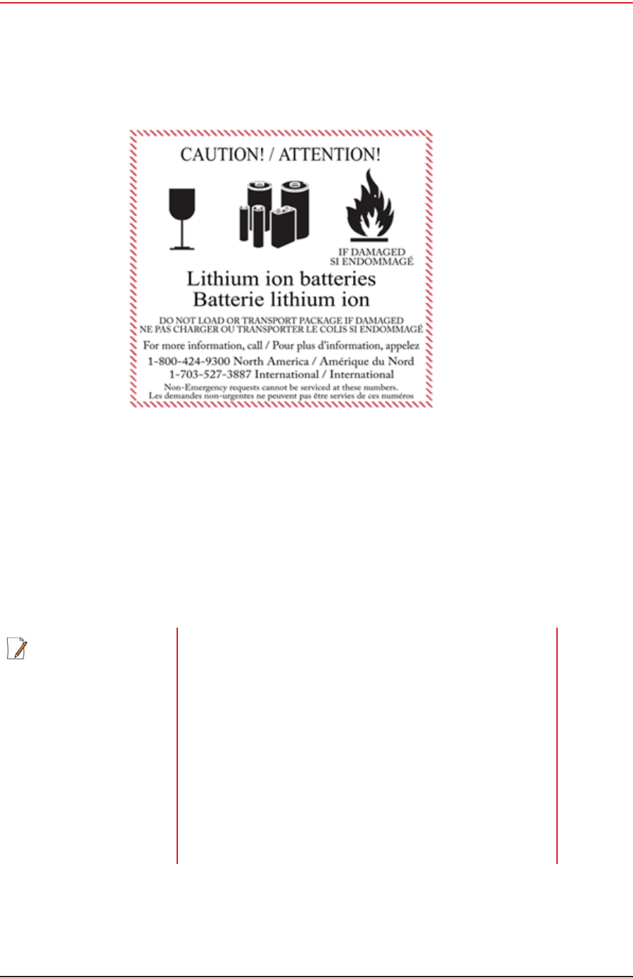
iLa boîte utilisée satisfait le test de chute de 1,2 m (boîte classée « UN ») de boîte
d'emballage
iLes bornes de bloc-batterie sont protégées pour éviter un court-circuit
iLe poids brut ne dépasse pas 30 kg (66 livres)
iL'emballage extérieur porte l'étiquette requise en vigueur. La figure suivante en montre
un exemple.
R01.i RT System 2 v2.3 Deployment Guide 197
© 2010-2014 Wireless Seismic, Inc. All rights reserved.
I. Français
Batteries
Les batteries ne peuvent être expédiées par voie aérienne que si toutes les conditions
suivantes sont satisfaites :
iLa boîte utilisée satisfait le test de chute de 1,2 m (boîte classée « UN ») de boîte
d'emballage
iLes bornes de bloc-batterie sont protégées pour éviter un court-circuit
iLe poids brut de chaque colis ne dépasse pas 10 kg (22 livres)
iL'emballage extérieur porte l'étiquette requise en vigueur. La figure précédente en
montre un exemple (“Example Battery Shipping Label” on page 197).
Exemple I–1 Example Battery Shipping Label
REMARQUE
Les informations contenues dans le présent document ont pour
but de fournir une connaissance générale des règlements
s'appliquant aux batteries. Elles ne sont pas exhaustives, et les
conditions mentionnées dans ce document peuvent avoir
changées. Rien dans le présent chapitre ou dans le Guide de
déploiement ne constitue un avis juridique ou est destiné à
répondre aux problèmes juridiques, de conformité, ou
réglementaires spécifiques qui peuvent survenir dans des
circonstances particulières. Le présent chapitre et le Guide de
déploiement ne sont pas destinés à remplacer les règlements
officiels en vigueur concernant l'emballage et l'expédition de
matières dangereuses ou un conseil juridique indépendant sur
c es questions. Vous êtes seul responsable du respect de
toutes les lois, règlements et autres exigences. Veuillez vous
reporter à une copie officielle de la version en vigueur de ces
documents pour obtenir les dernières informations.

198 RT System 2 v2.3 Deployment Guide R01.i
© 2010-2014 Wireless Seismic, Inc. All rights reserved.
I. Français
Batteries
I.1.1.4 Entreposage
Un entreposage et un entretien adéquats des batteries au lithium-ion est indispensable pour
optimiser leur durée de vie utile et éviter une défaillance catastrophique. Respecter les
précautions suivantes en matière d'entreposage :
iRetirer les batteries de l'unité distante sans fil avant l'entreposage
iTempérature d'entreposage recommandée des batteries au lithium-ion :
ƔDe -20°C à +45°C durant une période maximum d'un mois
ƔDe -20°C à +35°C durant 6 mois maximum ; passé ce délai, les blocs-batteries
doivent être rechargés à plus de 50 % de leur capacité
ƔL'entreposage à basses températures ralentit la décharge naturelle et la perte de
capacité au fil du temps. Entreposer les batteries à 25°C ou moins si possible
iNiveaux de charge d'entreposage recommandés :
ƔCharger (ou décharger) les batteries à un niveau de charge de 30 % à 50 % avant
de les entreposer. Des niveaux de charge inférieurs ou supérieurs peuvent réduire la
durée de vie des batteries.
ƔNe jamais entreposer des batteries entièrement déchargées, sauf en cas
d'élimination.
ƔUn chargement périodique est nécessaire pour maintenir une charge de 30 % à 50 %
en cas d'entreposage de longue durée
iEntreposer les batteries dans un endroit bien aéré
iNe pas laisser les batteries inutilisées pendant de longues durées, qu'elles soient dans le
produit ou placées en entreposage. Si une batterie n'a pas été utilisée pendant 6 mois,
vérifier l'état de charge et charger ou éliminer la batterie, le cas échéant.
iVérifier régulièrement l'état de charge de la batterie
iEnvisager le remplacement de la batterie par une nouvelle en cas de constat d'une des
conditions suivantes :
ƔL'autonomie de la batterie descend en dessous d'environ 80 % de son autonomie
initiale
ƔLe temps de charge de la batterie augmente sensiblement
I.1.2 Chargement des batteries au lithium-ion
Cette section décrit les précautions de chargement et présente le chargeur de batterie.
I.1.2.1 Précautions de chargement
Respecter les précautions de chargement suivantes :
iAvant de la charger, inspecter la batterie pour détecter les signes éventuels de
dommages sur le boîtier ou les connecteurs susceptibles de créer un court-circuit.
iLa batterie peut être chargée dans la plage de température de 0°Cà+45°C. En cas de
chargement de la batterie en dehors de cette plage, la batterie peut devenir très chaude
ou se rompre.
iÊtre absolument sûr de l'utilisation d'une source de 5 V lors du chargement de la
batterie.
iPrendre soin de charger les batteries sur une surface ininflammable.
iNe pas charger les batteries à proximité d'objets ou de liquides inflammables.
iConserver un extincteur à poudre chimique de classe C à proximité.
iNe pas continuer de recharger la batterie si elle ne se recharge pas dans le temps de
chargement spécifié.
iNE JAMAIS laisser une batterie au lithium-ion sans surveillance lorsqu'elle est en train de
charger.
R01.i RT System 2 v2.3 Deployment Guide 199
© 2010-2014 Wireless Seismic, Inc. All rights reserved.
I. Français
Batteries
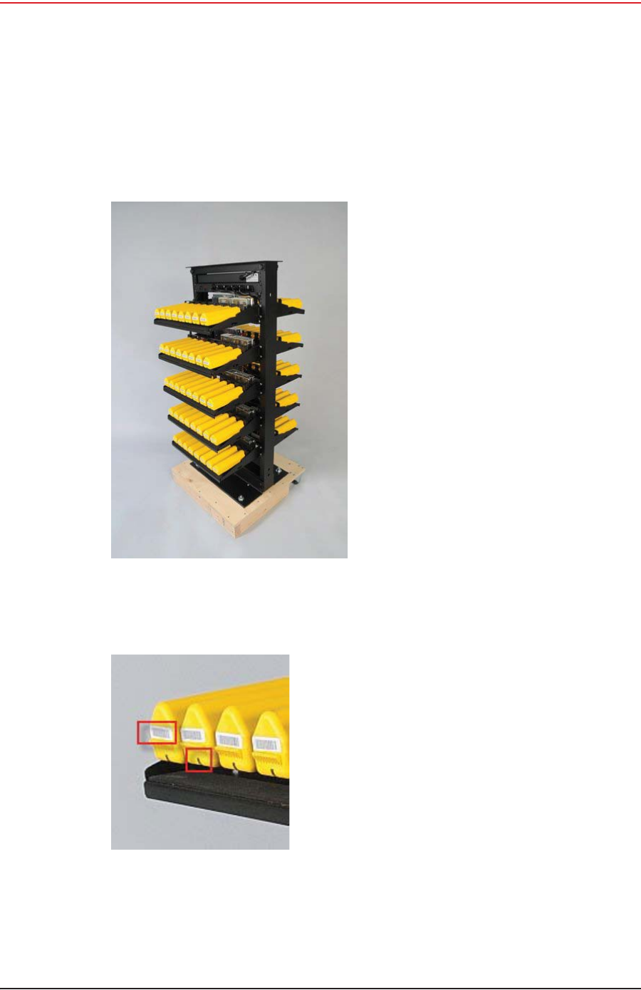
I.1.2.2 Chargeur de batterie
Le chargeur de batterie au lithium-ion est conçu pour fonctionner à partir d'une ligne de
service simple 120 V c.a., 10 A.
Le bloc d'alimentation servant à charger le bloc-batterie fournit une tension régulée de 5 V
c.c.
Exemple I–2 Chargeur de batterie
Exemple I–3 Étiquette avec
numéro de série et voyant
DEL

200 RT System 2 v2.3 Deployment Guide R01.i
© 2010-2014 Wireless Seismic, Inc. All rights reserved.
I. Français
l'information juridique
I.2 l'information juridique
I.2.1 Conformité avec les règles et règlements de la FCC
La Federal Communications Commission (FCC) règlemente l'utilisation d'antennes dans
l'article suivant : Code of Federal Regulations – Title 47, Part 15 – Radio Frequency Devices,
Subpart C – Intentional Radiators, Section 15.203 Antenna Requirement.
Lorsqu'il est utilisé comme prévu, le RT System 2 respecte les conditions de l'article 15.203
de la FCC et d'Industrie Canada CNR-Gen 7.1.2 de la manière suivante :
iLes antennes du RT System 2 doivent être installées et manipulées par des
professionnels spécifiquement désignés pour cela.
iLes changements ou modifications non expressément approuvés par Wireless Seismic,
Inc. peuvent annuler l'autorisation de l'utilisateur d'utiliser l'équipement.
iLe système RT 2 doit être utilisé uniquement avec les antennes fournies (Tableau I–2)
attachées à l’unité distante sans fil ou WRU (tous les modèles) ou à l’unité d’interface de
ligne ou LIU (tous les modèles) avec un connecteur (fileté ou HPQN) mâle de type N.
PRUDENCE
Le risque d'explosion si la batterie est remplacée par un type incorrect.
Débarrassez-vous utilisé batteries selon les instructions.
REMARQUE
Cet équipement a été testé et jugé conforme aux limites fixées pour un appareil
numérique de classe A, conformément à la partie 15 des règles de la FCC. Ces
limites sont conçues pour fournir une protection raisonnable contre les
interférences nuisibles lorsque l'équipement est utilisé dans un environnement
commercial. Cet équipement génère, utilise et peut émettre l'énergie des
fréquences radio et, s'il n'est pas installé et utilisé conformément au mode
d'emploi, peut causer des interférences nuisibles avec les communications
radio. Le fonctionnement de cet équipement dans une zone résidentielle est
susceptible de provoquer des interférences nuisibles, auquel cas l'utilisateur
devra corriger les interférences à ses propres frais.
REMARQUE
En vertu des règlementations d’Industrie Canada, cet émetteur radio peut être
utilisé uniquement à l’aide d’une antenne de type et de gain maximum (ou
inférieur) approuvés pour l’émetteur par Industrie Canada. Pour réduire les
interférences radio éventuelles avec d’autres utilisateurs, le type et le gain de
l’antenne doivent être choisis de sorte que la puissance isotrope rayonnée
équivalente (p.i.r.e.) ne dépasse pas la valeur nécessaire pour établir une
communication réussie.

R01.i RT System 2 v2.3 Deployment Guide 201
© 2010-2014 Wireless Seismic, Inc. All rights reserved.
I. Français
l'information juridique
L'autorisation d'équipement de FCC a été accordée comme suit :
iLe 5Mbps unité d'interface de ligne a reçu l'autorisation d'équipement.
iLe 5Mbps unité lointaine sans fil a reçu l'autorisation d'équipement.
I.2.2 Industrie Canada Conformité
L’unité distante sans fil (WRU) fournie avec ce guide a obtenu l’approbation
d’Industrie Canada (IC) ainsi que la certification en vertu de l’édition 8 de la norme RSS-210
et de l’édition 4 de la norme RSS-102.
Cet appareil numérique de la classe A est conforme à la norme NMB-003 du Canada.
L’unté d’interface de ligne (LIU) fournie avec ce guide a obtenu l’approbation
d’Industrie Canada (IC) ainsi que la certification en vertu de l’édition 8 de la norme RSS-210
et de l’édition 4 de la norme RSS-102.
Cet appareil numérique de la classe A est conforme à la norme NMB-003 du Canada.
Cet appareil est conforme avec I'industrie Canada licence exemptes des normes. Son
fonctionnement est soumis aux deux conditions suivantes :
iCe dispositif ne peut causer des interférences, et
iCe dispositif doit accepter toute interférence, y compris les interférences qui peuvent
causer un mauvais fonctionnement du dispositif.
REMARQUE
Cet émetteur radio a été approuvé par Industrie Canada pour fonctionner avec
les types d’antenne énumérés ci-dessous. Le gain maximum permis et
l’impédance d’antenne requise pour chaque antenne sont indiqués. Les types
d’antenne non inclus dans cette liste, ayant un gain supérieur au gain maximum
indiqué pour le type en question, sont strictement interdits pour ce dispositif.
Tableau I–2 Spécifications des antennes
Modèle Fréquence
(MHz) Gain Maximal Bande
passante
verticale Poids Dimensions
(longueur x dia
mètre)
WSI 65-0204/65-0264
(antenna standard) 2400 5,5 dBi (50 ohms) 25° 0.4 lbs
0.2 kg 32 x 0,6 po
810.5 x 15 mm
WSI 65-0091
(extenseur standard) 2400 0 dBi s.o. 0.6 lbs
0.3 kg 30 x 0,7 po
762 x 18,5 mm
PRUDENCE
Afin de se conformer aux normes de la matière d'exposition aux
radiofréquences (RF), les unités RT System 2 doivent être installées de
manière à garder en permanence une distance minimale de 20 cm entre la
ou les antennes et le corps de toute personne en mode de fonctionnement
normal.

202 RT System 2 v2.3 Deployment Guide R01.i
© 2010-2014 Wireless Seismic, Inc. All rights reserved.
I. Français
l'information juridique
I.2.3 Acquiescement de CE
L’unité distante sans fil (WRU) et l’unité d’interface de ligne (LIU) fournies avec ce guide sont
conformes aux directives applicables de l’UE pour la marque de Conformité européenne (CE).
La marque suivante est apposée sur chaque unité.
Exemple I–4 Marque de CE

RT System 2 v2.3 203 Deployment Guide R01.i
© 2010-2014 Wireless Seismic, Inc. All rights reserved.
Index
Numerics
12 V DC 39
19 dBi directional antenna 149
5.8 GHz band 38
56-0032 INTL 71
56-0035 US 71
6 dBi antenna 149
65-0091 18
90-0026 10
90-0028 10
90-0032 10
90-0039 10
A
access point radio 67
Acquiring GPS fix 169
anchor plate 23
antenna
attach 18
bracket 56
connecting 18
extender 18
extenders 11
specifications 39, 44, 145
antennas 39, 144
radio 44
anti-tipping 23
armored cable 59
assemble
the backhaul 50
the ground equipment 16
auto-power-leveling 39
B
B 169, 175
backhaul 26, 31
components 31
masts 49
power requirements 39
Backpack Kit 31
base 49, 51
tips 50
batteries
attach 16
battery
charge time 12
charger 142
charger location 12
charging 142
failure 179
fuse test failure 166
handling and safety guidelines 139
latch 16
remove 136
shipments 140
specifications 138
storage 141
Battery A in use 172, 173
Battery B in use 172, 173
battery failure 179
browser pop-ups 121
Bucket Brigade 26
C
cable
Armored Ethernet 45
clamp 55
Ethernet 45
LIU to Battery 45
LIU to NanoStation radio 45
LIU-to-PC 45
RF Extender 45
Shielded Ethernet 45
cables 59, 63
central 31
clamps 63
color-coded 67
compass 184
contact 10
Continue 168
country codes for radios 71
CSS 27
custom number of recorder radios 119
D
data flow 28
declination 184
deploy
at actual location 14
deviation 185
disassemble the WRU 136
discharge 138
discover and configure the radios 71, 106
Dummy Batteries 11
E
elbow connector 59
Elevation Profile 77, 113
error
Geophone failure 169
indicators 163
No GPS fix 169
No neighbor detected 170
Self test failure 174
Error LEDs 168
Ethernet cable
non-powered 80
powered 80
extreme temperature charging 138
F
FCC 144
Section 15.203 144
Fiber Backhaul Kit 32, 45
fiber cables 68
fiber optic cable 38
figure
Tripod Assembly – Front View 183
final speed test 119
firmware
upgrade 181
Formed 178
four-line, dual-backhaul line 29
frequency
International 71
United States of America 71
fuse test failure 166

Index
G
R01.i RT System 2 v2.3 Deployment Guide 204
© 2010-2014 Wireless Seismic, Inc. All rights reserved.
G
geographic north 184
geophone 17
Geophone test in progress 168
Global Mapper 77
Google Earth 77, 113
GPS acquire position 21
antenna 59
disciplined 177
error 169
LED flashing 21
lock 21, 177
lock, not disciplined 180
no discipline 179
no lock 180
green-to-green 59
ground 63
equipment 11
wire 59, 63
ground equipment
assemble 16
guy lines 60, 61
ring 54, 55, 56
H
help 10
hopping 26
hose clamp 52
I
Industrial, Scientific, and Medical radio band 27
Industry Canada RSS-Gen 7.1.2 144
install and troubleshoot the radios 78
ISM 27
ISO 3166-1 71
L
LED dead batteries 164, 166, 172, 173
reset pattern 176
sleeping 164, 166, 172, 173
status 163
undeployed 164, 166, 172, 173
line radio 39, 52
kit 32
line station 31
LIU 38
A, flashing 179
A, solid 177, 178
all off 175
B, flashing 179
B, solid 177, 178
BAT, flashing 178, 179
BAT, solid 178
Disciplined to GPS 177
GPS, flashing 177, 178, 179
GPS, off 180
GPS, solid 177, 180
hard reset 176
LEDs 175
LNK, flashing 178, 179
LNK, off 179
LNK, solid 177, 178
MODE, flashing 177, 178, 179
MODE, solid 177
power on LED rotation 176
RAD, flashing 178
RAD, solid 178
LIU connected to Central 177
LIU Kit 31
locate an object using a map and a compass 185
loop knot 188
M
magnetic
north 184
objects near a compass 185
mast 49, 51, 61, 62, 182
assemble 54
collar 60
kit 31
masts 49
modifications 144
N
Neighbor
discovered 169
discovery in progress 169
no communications with Central 179
GPS discipline 179
GPS lock 180
IP Address 179
node 26
O
obstructions 50
one recorder, multiple line station radios 117
overcharge 138
P
pendant link 72
pendant radio connection 96
pendant radio link connections 95
PoE 27
injector 27
switch 27
Point-to-Multipoint 26
Point-to-Point 26
pole pairs 67
power off WRU 135
Power over Ethernet 27
power-leveling 39
private network 72, 107
R
radio
Access Point (A) 67
configuration 70
configuration files 71, 106
configure 117
country codes 71
create an Elevation Profile 77
credentials 74
default IP Address 73
error message 71
frequencies 105
install and troubleshoot 115
label 67
link to recording truck 72
location plan 76
multiple line station 117
one recorder 117
pairs 67
prepare 70, 104
recorder 119
redundant recorder 118
replacing 90
set power level 97

Index
S
205 RT System 2 v2.3 Deployment Guide R01.i
© 2010-2014 Wireless Seismic, Inc. All rights reserved.
shielding 85
speed test 80
Station (S) 67
upload configuration file 75
upload new firmware 90
version 70
versions 105
recorder 31
radio 43
Recorder Radio Kit 33, 34
recording truck 31
recording truck connection
fiber cable 92
optimal angle pendant to line 94
radio link (pendant) 93
redundant recorder radio 118
relay 26
remote 31
remove battery 136
repeater 19
rolling the backhaul 86
run the speed test 82, 120
S
self test 168
fails 22
failure 21
in progress 168
set the PN radio power level 97
short circuit 138
single-backhaul line 28
skip a self-test 22
a test 168
slope 50
specifications
antenna 39, 44, 145
stakes 52, 61
star configuration 26, 30
static IP address 72
station radio 67
status
Acquiring GPS fix 169
Battery A in use 172, 173
Battery B in use 172, 173
Continue 168
Geophone test in progress 168
Neighbor discovered 169
Neighbor discovery in progress 169
self test in progress 168
Undeployed 164, 172, 173
String-of-Pearls 26
supported
antennas 39, 44, 145
Surge Protector 34, 44, 59, 60
ground wire 63
T
THD test failure 169
tie a taut-line hitch knot 188
tipping, preventing 23
tripod assembly 183
true north 184
U
Ubiquiti Discovery Tool 71, 106
download 73
undeploy the WRU 135
undeployed 136, 164, 172, 173
unzip
7-Zip 91, 129
Windows 7 91, 129
upload new firmware 128
upload new radio firmware 90
users 10
W
white-to-white 59
wind 51
WRUA, flashing 169, 172, 173, 175
A, solid 166
B, flashing 169, 172, 173, 175
B, solid 167
BAT, flashing 168, 181
BAT, solid 166, 167, 174
GEO, flashing 168, 181
GEO, solid 168, 169, 174
GPS, flashing 168, 169
GPS, solid 168, 169, 174
hard reset 165, 171
MODE, flashing 168, 169, 175
MODE, solid 168, 180
no LEDs 164, 166, 172, 173
power off 135
power on 19
power on LED rotation 165, 171
RAD, flashing 168, 169, 181
RAD, solid 170, 174
tests 21