ZTE R8882S8500 ZXSDR R8882 S8500 is Macro Radio Remote Unit User Manual II
ZTE Corporation ZXSDR R8882 S8500 is Macro Radio Remote Unit II
ZTE >
Contents
User Manual II

ZXSDRR8882
MacroRadioRemoteUnit
HardwareDescription
HardwareVersion:HV2.0
ZTECORPORATION
NO.55,Hi-techRoadSouth,ShenZhen,P .R.China
Postcode:518057
Tel:+86-755-26771900
Fax:+86-755-26770801
URL:http://ensupport.zte.com.cn
E-mail:support@zte.com.cn

LEGALINFORMATION
Copyright©2011ZTECORPORATION.
Thecontentsofthisdocumentareprotectedbycopyrightlawsandinternationaltreaties.Anyreproductionor
distributionofthisdocumentoranyportionofthisdocument,inanyformbyanymeans,withoutthepriorwritten
consentofZTECORPORATIONisprohibited.Additionally,thecontentsofthisdocumentareprotectedby
contractualcondentialityobligations.
Allcompany,brandandproductnamesaretradeorservicemarks,orregisteredtradeorservicemarks,ofZTE
CORPORATIONoroftheirrespectiveowners.
Thisdocumentisprovided“asis”,andallexpress,implied,orstatutorywarranties,representationsorconditions
aredisclaimed,includingwithoutlimitationanyimpliedwarrantyofmerchantability,tnessforaparticularpurpose,
titleornon-infringement.ZTECORPORATIONanditslicensorsshallnotbeliablefordamagesresultingfromthe
useoforrelianceontheinformationcontainedherein.
ZTECORPORATIONoritslicensorsmayhavecurrentorpendingintellectualpropertyrightsorapplications
coveringthesubjectmatterofthisdocument.ExceptasexpresslyprovidedinanywrittenlicensebetweenZTE
CORPORATIONanditslicensee,theuserofthisdocumentshallnotacquireanylicensetothesubjectmatter
herein.
ZTECORPORATIONreservestherighttoupgradeormaketechnicalchangetothisproductwithoutfurthernotice.
UsersmayvisitZTEtechnicalsupportwebsitehttp://ensupport.zte.com.cntoinquirerelatedinformation.
TheultimaterighttointerpretthisproductresidesinZTECORPORATION.
RevisionHistory
SerialNo.PublishingDatePublishingReason
R1.12012–01–30Updatedthefollowingsections:
lChapter1,ProductAppearance
lChapter2,ExternalInterfaces
lChapter3,Indicators
lSection4.2,ProtectiveGroundingCable
lSection4.3,DCPowerInputCable
lSection4.6,ExternalMonitoringCable
lSection4.7,AISGControlCable
R1.02011–10–30FirstEdition
SerialNumber:SJ-20111021104623-003
PublishingDate:2012–01–30(R1.1)

AboutThisManual
Purpose
ThismanualdescribestheZXSDRR8882device,includingthechassisandexternal
cables.
IntendedAudience
Thismanualisintendedforthefollowingpersonnel:
lEquipmentinstallationengineers
lMaintenanceengineers
WhatIsinThisManual
Thismanualcontainsthefollowingchapters.
ChapterSummary
Chapter1,Product
Appearance
DescribestheoverallappearanceanddimensionsofZXSDRR8882.
Chapter2,External
Interface
DescribestheexternalinterfacesofZXSDRR8882.
Chapter3,IndicatorsDescribestheindicatorsontheZXSDRR8882chassis.
Chapter4,External
Cables
DescribestheexternalcablesusedfortheZXSDRR8882chassis.
Conventions
Thismanualusesthefollowingtypographicalconventions:
TypefaceMeaning
ItalicsVariablesincommands.Itmayalsorefertootherrelatedmanuals
anddocuments.
BoldMenus,menuoptions,functionnames,inputelds,optionbutton
names,checkboxes,drop-downlists,dialogboxnames,window
names,parametersandcommands.
CAPSKeysonthekeyboardandbuttonsonscreensandcompanyname.
ConstantwidthTextthatyoutype,programcodes,lenames,directorynames,
functionnames.
[]Optionalparameters.
{}Mandatoryparameters.
|Separatesindividualparameterinseriesofparameters.
I

TypefaceMeaning
Danger:indicatesanimminentlyhazardoussituation.Failureto
complycanresultindeathorseriousinjury,equipmentdamage,
orsitebreakdown.
Warning:indicatesapotentiallyhazardoussituation.Failure
tocomplycanresultinseriousinjury,equipmentdamage,or
interruptionofmajorservices.
Caution:indicatesapotentiallyhazardoussituation.Failureto
complycanresultinmoderateinjury,equipmentdamage,or
interruptionofminorservices.
Note:providesadditionalinformationaboutacertaintopic.
II

Contents
AboutThisManual.........................................................................................I
Chapter1ProductAppearance.................................................................1-1
Chapter2ExternalInterfaces....................................................................2-1
Chapter3Indicators...................................................................................3-1
Chapter4ExternalCables.........................................................................4-1
4.1Overview...........................................................................................................4-1
4.2ProtectiveGroundingCable................................................................................4-1
4.3DCPowerInputCable........................................................................................4-2
4.4AntennaFeederCable........................................................................................4-3
4.5FiberCable........................................................................................................4-3
4.6ExternalMonitoringCable...................................................................................4-4
4.7AISGControlCable............................................................................................4-5
Figures.............................................................................................................I
Tables............................................................................................................III
Index...............................................................................................................V
Glossary.......................................................................................................VII
I

II
Chapter1
ProductAppearance
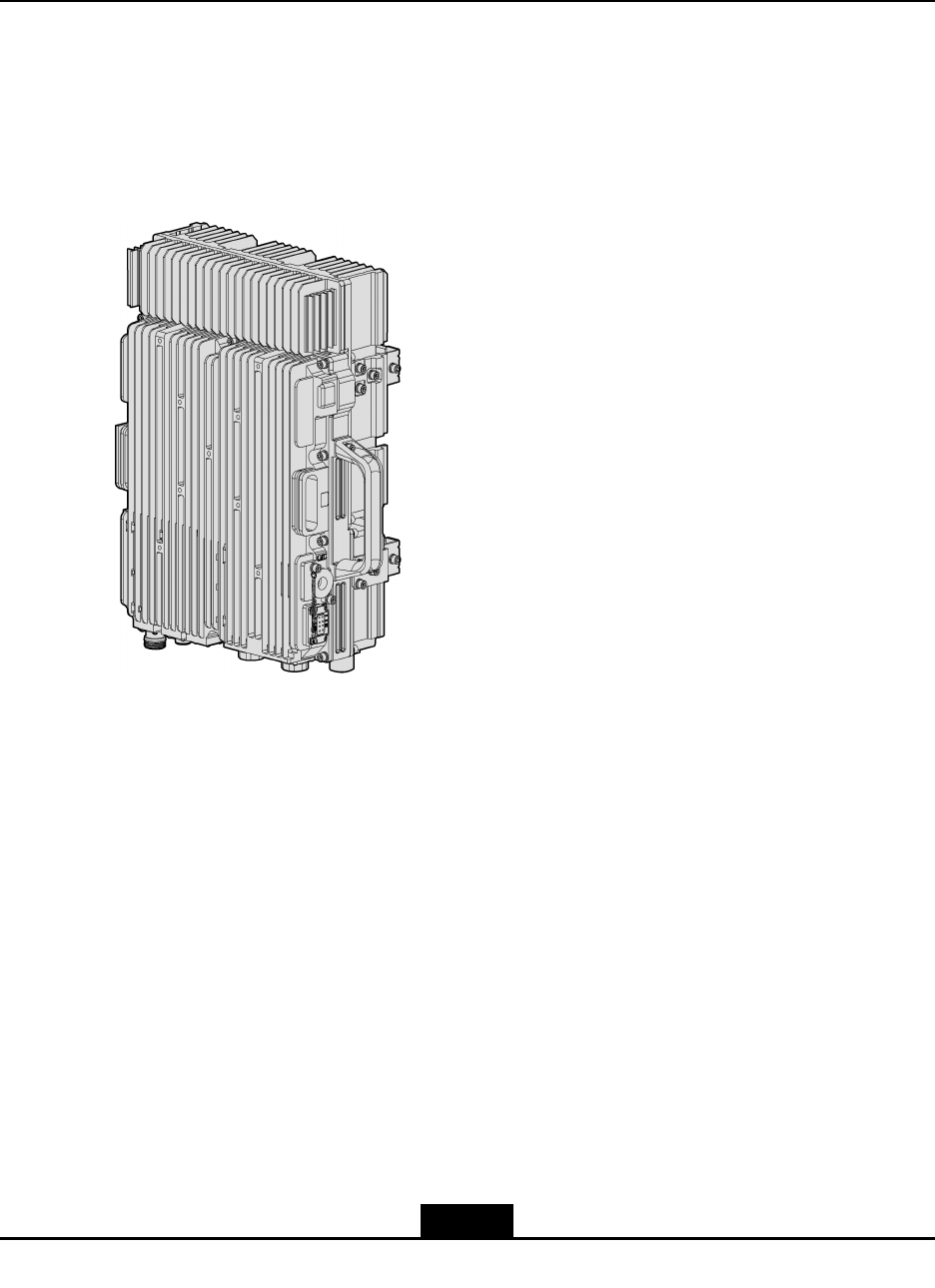
TheZXSDRR8882hastwomodels:ZXSDRR8882withtwoopticalportsandZXSDR
R8882withthreeopticalports.
Figure1-1showstheappearanceoftheZXSDRR8882withtwoopticalports.
Figure1-1AppearanceoftheZXSDRR8882withTwoOpticalPorts
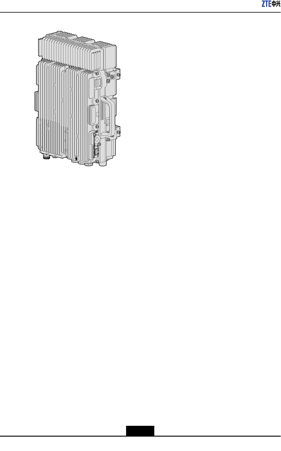
Figure1-2showstheappearanceoftheZXSDRR8882withthreeopticalports.
1-1
SJ-20111021104623-003|2012–01–30(R1.1)ZTEProprietaryandCondential
ZXSDRR8882HardwareDescription
Figure1-2AppearanceoftheZXSDRR8882withThreeOpticalPorts
Dimensions:480mmx320mmx150mm(HeightxWidthxDepth)
Weight:27kg
1-2
SJ-20111021104623-003|2012–01–30(R1.1)ZTEProprietaryandCondential
Chapter2
ExternalInterfaces
TheZXSDRR8882chassishastwomodels:twoopticalinterfacesandthreeoptical
interfaces.
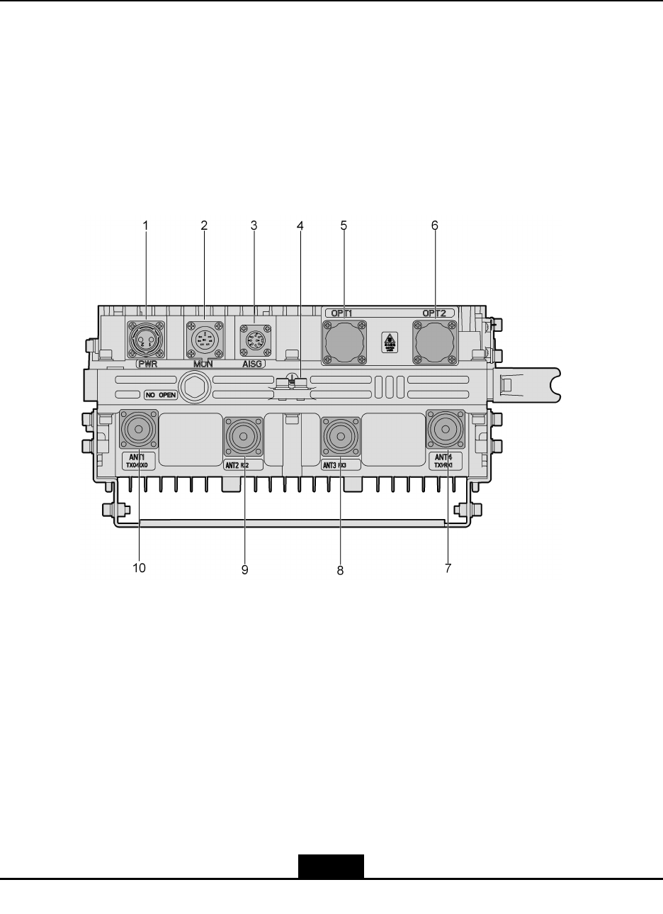
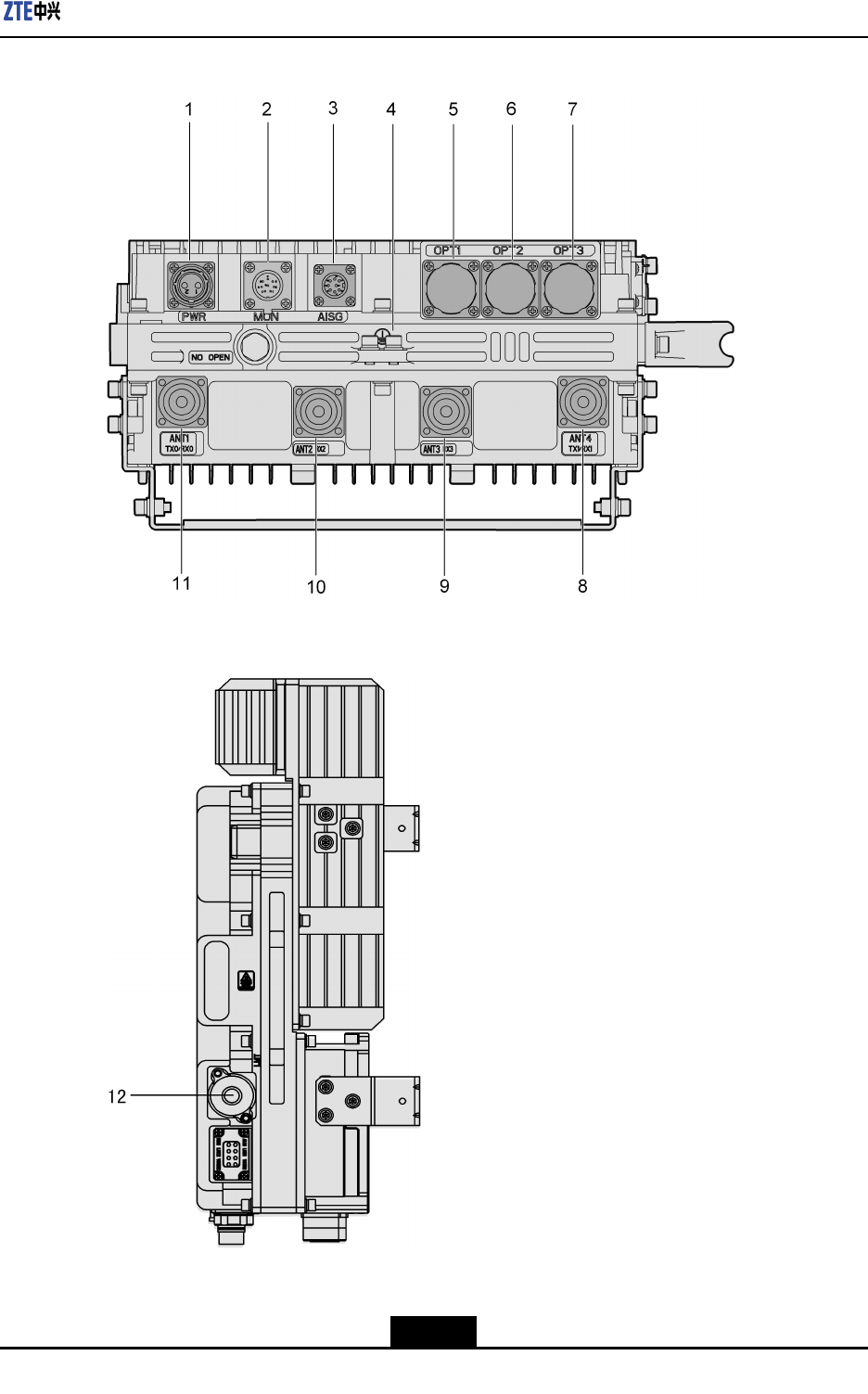
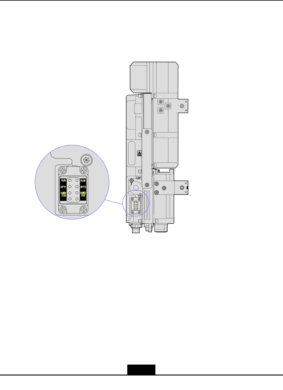
ExternalInterfaces(TwoOpticalInterfaces)
ExternalinterfacesaredistributedatthebottomandtherightsideoftheZXSDRR8882
chassis,asshowninFigure2-1andFigure2-2.
Figure2-1ExternalInterfacesattheBottom(TwoOpticalInterfaces)
2-1
SJ-20111021104623-003|2012–01–30(R1.1)ZTEProprietaryandCondential
ZXSDRR8882HardwareDescription
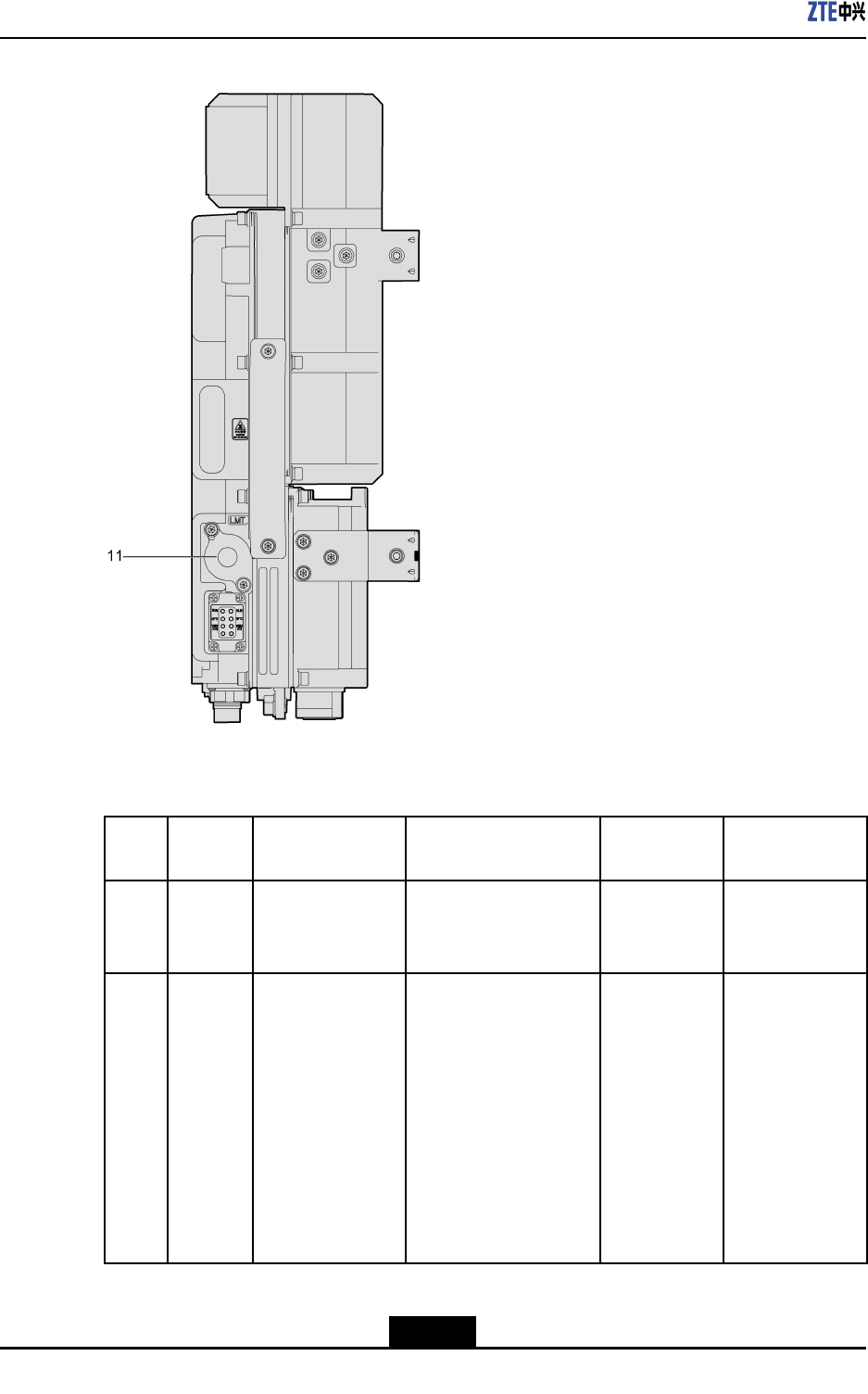
Figure2-2ExternalInterfaceattheRightSide(TwoOpticalInterfaces)
Table2-1describestheexternalinterfacesofZXSDRR8882.
Table2-1ExternalInterfaceDescription(TwoOpticalInterfaces)
No.Silkscr-
een
InterfaceConnectorTypeCompliant
Protocol
Function
1PWR-48VDCpower
inputinterface
2-pinroundplastic
connector(male)
-Provides-48
VDCpower
supply.
2MONExternal
monitoring
interface
8-pinstraightpanel
mountroundsocket
(male)
-Supports
interactionof
signalsbetween
theRRUand
externaldevices,
including
alarmsignals,
RS485/RS422
controlsignals,
andtwopairsof
2-2
SJ-20111021104623-003|2012–01–30(R1.1)ZTEProprietaryandCondential

Chapter2ExternalInterfaces
No.Silkscr-
een
InterfaceConnectorTypeCompliant
Protocol
Function
drycontactinput
signals.
3AISGAISGinterface8-pinsocketwitha
squarebase
AISGSupportsthe
connectiontoan
RETantenna.
4-PEinterface16mm2yellow-green
roundterminal
-Provides
protectiveearth.
5OPT1Interfacefor
connectingBBU
andRRU,or
cascadingRRUs
LCconnector(IEC874)Private
protocolof
ZTE
6OPT2Interfacefor
connectingBBU
andRRU,or
cascadingRRUs
LCconnector(IEC874)Private
protocolof
ZTE
Supportssignal
transmission
betweenRRU
andBBU,or
betweenRRUs.
7ANT4
TX1/
RX1
Antennafeeder
interface
(Tx1/Rx1)
DINconnector-
Transmitsand
receivesradio
signalson
channel1.A1/2"
foamdielectric
cable(50Ω)is
usedtoconnect
thisinterfaceto
anantenna.
8ANT3
RX3
Antennafeeder
interface(Rx3)
DINconnector-Receivesradio
signalson
channel3.It
implements
thediversity
receivingof
radiosignalfor
channel1.
2-3
SJ-20111021104623-003|2012–01–30(R1.1)ZTEProprietaryandCondential

ZXSDRR8882HardwareDescription
No.Silkscr-
een
InterfaceConnectorTypeCompliant
Protocol
Function
9ANT2
RX2
Antennafeeder
interface(Rx2)
DINconnector-Receivesradio
signalson
channel2.It
implements
thediversity
receivingof
radiosignalfor
channel0.
10ANT1
TX0/
RX0
Antennafeeder
interface
(Tx0/Rx0)
DINconnector-Transmitsand
receivesradio
signalson
channel0.
11LMTEthernetinterface
foroperationand
maintenance
8P8Cshieldedright
anglePCBmountjack
withLED(leftyellow,
rightgreen)
-Supports
operationand
maintenanceon
theRRU,and
outputsinternal
signals.
ExternalInterfaces(ThreeOpticalInterfaces)
TheexternalinterfacesaredistributedatthebottomandtherightsideoftheZXSDRR8882
chassis,asshowninFigure2-3andFigure2-4.
2-4
SJ-20111021104623-003|2012–01–30(R1.1)ZTEProprietaryandCondential

ZXSDRR8882HardwareDescription
Table2-2ExternalInterfaces
No.Silkscr-
een
InterfaceConnectorTypeCompliant
Protocol
Function
1PWR-48VDCpower
inputinterface
2-pinroundplastic
connector(male)
-Supportstheinputof-48V
DCpowerandprovidesa
drycontact.
2MONExternalmonitoring
interface
8-pinstraightpanel
mountroundsocket
(male)
-Supportsinteractionof
signalsbetweentheRRU
andexternaldevices,
includingalarmsignals,
RS485/RS422control
signals,andtwopairsof
drycontactinputsignals.
3AISGAISGinterface8-pinsocketwitha
squarebase
AISGSupportstheconnectionto
anRETantenna.
4-PEinterface16mm2yellow-green
roundterminal
-Providesprotectiveearth.
5OPT1Interfacefor
connectingBBU
andRRU,or
cascadingRRUs
LCconnector(IEC
874)
Privateprotocolof
ZTE
6OPT2Interfacefor
connectingBBU
andRRU,or
cascadingRRUs
LCconnector(IEC
874)
Privateprotocolof
ZTE
Supportssignal
transmissionbetween
RRUandBBU,orbetween
RRUs.
7OPT3Interfacefor
cascadingRRUs
onthesamebranch
LCconnector(IEC
874)
Privateprotocolof
ZTE
Supportssignal
transmissionbetween
RRUs.
8ANT4
TX1/
RX1
Antennainterface
(Tx1/Rx1)
DINconnector-Transmitsandreceives
radiosignalsonchannel
1.A1/2"foamdielectric
cable(50Ω)isusedto
connectthisinterfacetoan
antenna.
9ANT3
RX3
Antennainterface
(Rx3)
DINconnector-Receivesradiosignalson
channel3.Itimplements
thediversityreceivingof
radiosignalforchannel1.
2-6
SJ-20111021104623-003|2012–01–30(R1.1)ZTEProprietaryandCondential

Chapter2ExternalInterfaces
No.Silkscr-
een
InterfaceConnectorTypeCompliant
Protocol
Function
10ANT2
RX2
Antennainterface
(Rx2)
DINconnector-Receivesradiosignalson
channel2.Itimplements
thediversityreceivingof
radiosignalforchannel0.
11ANT1
TX0/
RX0
Antennainterface
(Tx0/Rx0)
DINconnector-Transmitsandreceives
radiosignalsonchannel0.
12LMTEthernetinterface
foroperationand
maintenance
8P8Cshieldedright
anglePCBmountjack
withLED(leftyellow,
rightgreen)
-Supportsoperationand
maintenanceonthe
RRU,andoutputsinternal
signals.
2-7
SJ-20111021104623-003|2012–01–30(R1.1)ZTEProprietaryandCondential

ZXSDRR8882HardwareDescription
Thispageintentionallyleftblank.
2-8
SJ-20111021104623-003|2012–01–30(R1.1)ZTEProprietaryandCondential
Chapter3
Indicators
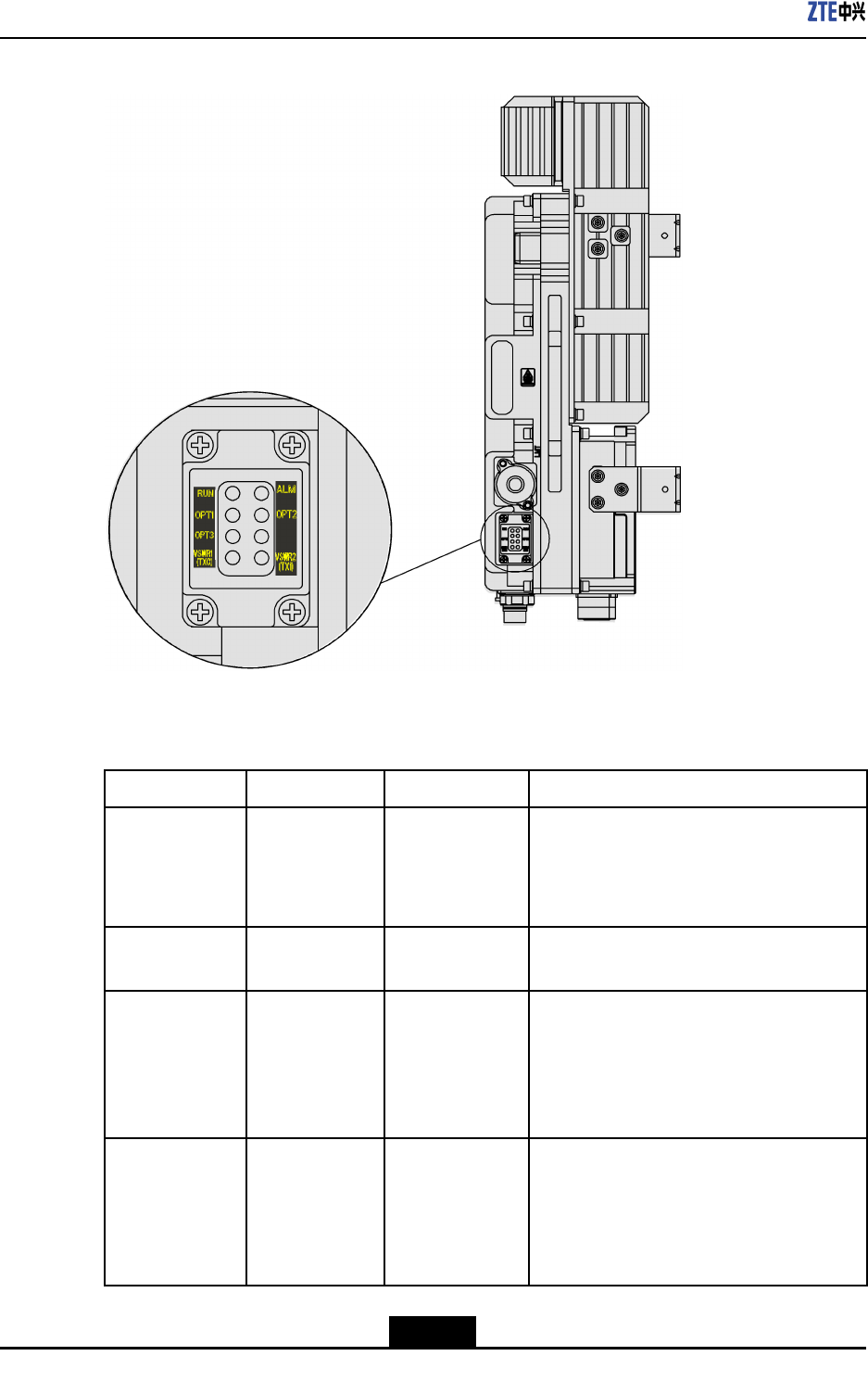
Theindicators,locatedatthebottomoftheZXSDRR8882chassis,displaytheoperating
statusofthedevice.Figure3-1andFigure3-2respectivelyshowtheindicatorsona
ZXSDRR8882thathastwoopticalinterfacesandthreeopticalinterfaces.
Figure3-1IndicatorsoftheRRU(TwoOpticalInterfaces)
3-1
SJ-20111021104623-003|2012–01–30(R1.1)ZTEProprietaryandCondential
ZXSDRR8882HardwareDescription
Figure3-2IndicatorsoftheRRU(ThreeOpticalInterfaces)
Table3-1describestheseindicators.
Table3-1IndicatorDescription
NameMeaningLEDColorOperationMode
RUNPower-onstatusGreen
Flashingat2Hz:normalsystemoperation
Litandotherblinkingmodes:systembeing
startedorabnormalsystem
Notlit:systemnotpoweredon
ALMAlarmindicationRedLit:alarm
Notlit:noalarm
OPT1Statusofoptical
interface1Green
Flashing:normalopticalport1
Lit:abnormalopticalport1(withoptical
signals)
Notlit:abnormalopticalport1(without
opticalsignals)
OPT2Statusofoptical
interface2Green
Flashing:normalopticalport2
Lit:abnormalopticalport2(withoptical
signals)
Notlit:abnormalopticalport2(without
opticalsignals)
3-2
SJ-20111021104623-003|2012–01–30(R1.1)ZTEProprietaryandCondential
Chapter3Indicators
NameMeaningLEDColorOperationMode
OPT3Statusofoptical
interface3Green
Flashing:normalopticalport3
Lit:abnormalopticalport3(withoptical
signals)
Notlit:abnormalopticalport3(without
opticalsignals)
VSWR1(TX0)VSWRstatusof
Tx0RedLit:TX0antennaVSWRalarm
Notlit:normalTX0antennaVSWR
VSWR2(TX1)VSWRstatusof
Tx1RedLit:TX1antennaVSWRalarm
Notlit:normalTX1antennaVSWR
Note:
ThereisnoOPT3indicatoronZXSDRR8882chassiswithtwoopticalinterfaces.
3-3
SJ-20111021104623-003|2012–01–30(R1.1)ZTEProprietaryandCondential

ZXSDRR8882HardwareDescription
Thispageintentionallyleftblank.
3-4
SJ-20111021104623-003|2012–01–30(R1.1)ZTEProprietaryandCondential
Chapter4
ExternalCables
TableofContents
Overview....................................................................................................................4-1
ProtectiveGroundingCable........................................................................................4-1
DCPowerInputCable................................................................................................4-2
AntennaFeederCable...............................................................................................4-3
FiberCable................................................................................................................4-3
ExternalMonitoringCable..........................................................................................4-4
AISGControlCable....................................................................................................4-5
4.1Overview
ThischapterdescribestheexternalcablesofZXSDRR8882.
Theexternalcablesareasfollows:
lProtectivegroundingcable
lDCpowerinputcable
lAntennafeedercable
lFibercable
lExternalmonitoringcable
lAntennaInterfaceStandardsGroup(AISG)controlcable
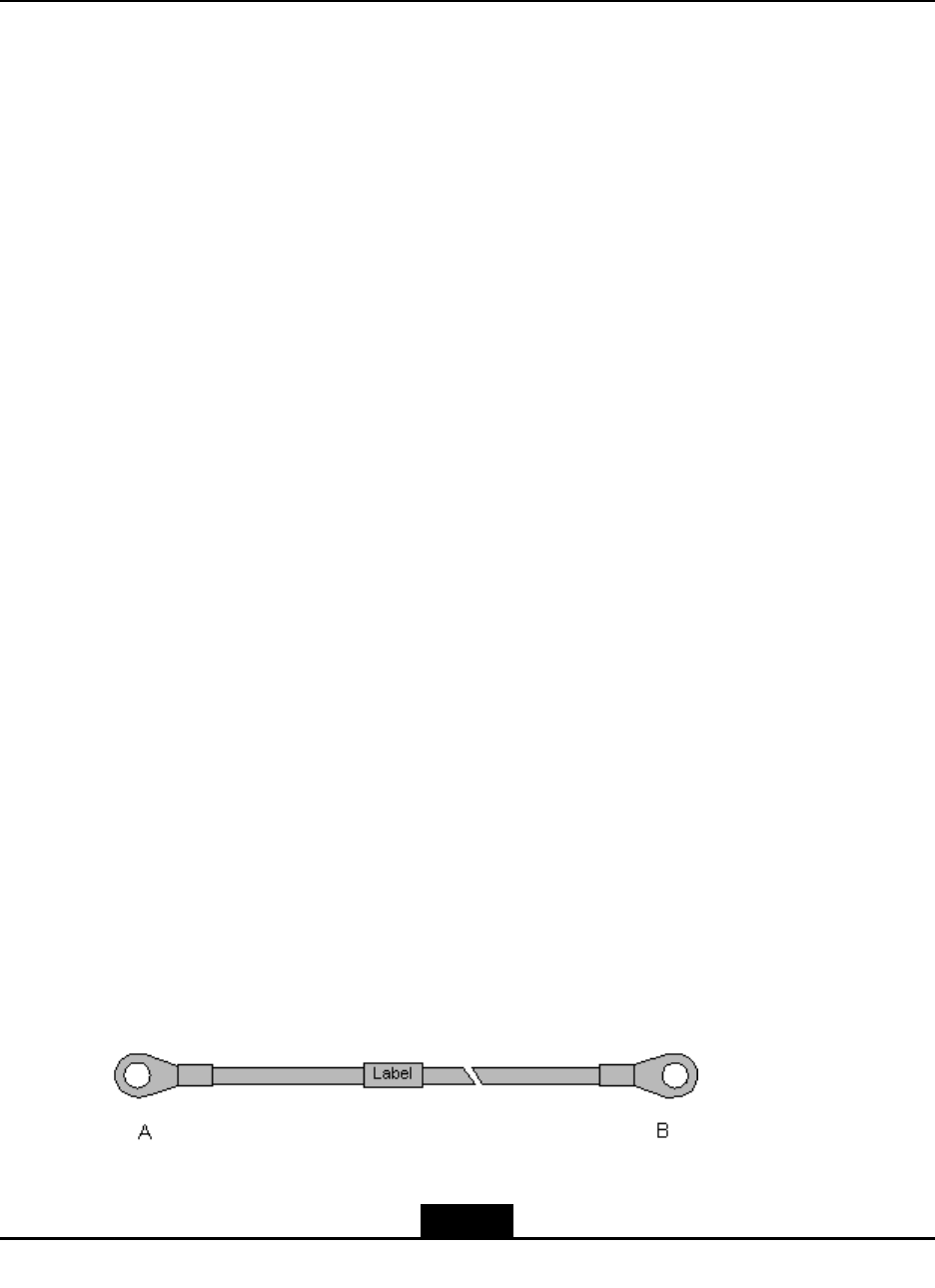
4.2ProtectiveGroundingCable
Function
TheprotectivegroundingcableprovidesprotectiveearthfortheZXSDRR8882chassis.
ExternalView
Thiscableisa16mm2green-yellowcable.ATNR22-8lugiscrimpedonbothends,as
showninFigure4-1.
Figure4-1AppearanceoftheProtectiveGroundingCable
4-1
SJ-20111021104623-003|2012–01–30(R1.1)ZTEProprietaryandCondential
ZXSDRR8882HardwareDescription
SignalDenition
NameDenitionPin(EndA)Pin(EndB)CoreColor
PEProtectiveearth--Green-yellow
Connections
lEndBisconnectedtothegroundingbarandtightenedwithabolt.
lEndAisconnectedtotheprotectivegroundingterminalontheZXSDRR8882chassis
andtightenedwithabolt.
Note:
IfthereisaPIMDClightningprotectionbox,endAoftheprotectivegroundingcableis
connectedwiththeprotectivegroundingportoftheZXSDRR8882.EndBisconnected
withthelightningprotectionboxandthenconnectedwiththegroundingbarthroughthe
box.
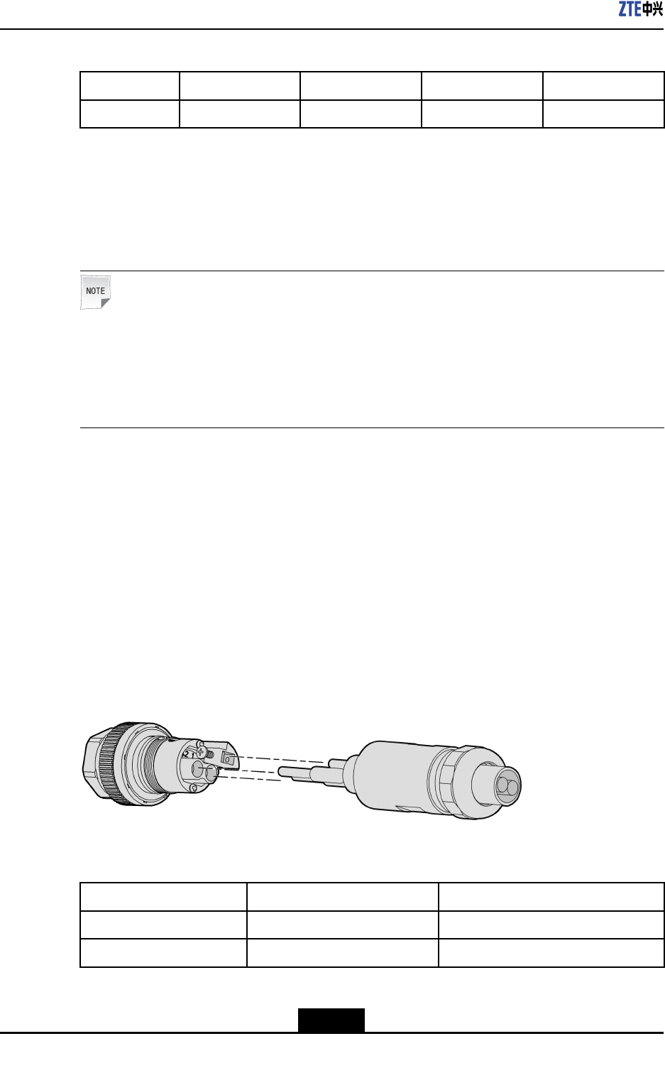
4.3DCPowerInputCable
Function
TheDCpowerinputcableprovidestheinputof-48VDCpowerfortheZXSDRR8882
chassis.
ExternalView
Figure4-2showstheappearanceoftheDCpowerinputcable.
Figure4-2AppearanceoftheDCPowerInputCable
SignalDenition
NameDenitionCoreColor
-48V-48VDCpowerBlue
-48VGND-48VDCgroundBlack
4-2
SJ-20111021104623-003|2012–01–30(R1.1)ZTEProprietaryandCondential
Chapter4ExternalCables
Connections
lEndAisconnectedtothePWRinterfaceofZXSDRR8882.
lEndBisconnectedtothecorrespondingterminalsonthepowersupplyadapter.
Note:
TheEPBCembeddedlightningarresterisusedforthedeviceandthereforeexternal
signalsarenottransmittedthroughthecabletransitbox.Duringinstallation,theeld
engineerneedstomakeacableonsiteinaccordancewiththeavailablepoweraviation
headandconnectthepowercablewiththepowerconnector.
4.4AntennaFeederCable
Function
TheantennafeedercableconnectstheantennafeederinterfaceontheZXSDRR8882
chassistothemainfeeder,supportingtransmittingandreceivingofradiosignals.
ExternalView
Thiscableisan1/2"RFcable(50Ω).ADINconnectorismountedonbothends,asshown
inFigure4-3.
Figure4-3AppearanceoftheAntennaCable
SignalDenition
None
Connections
lOneendisconnectedtotheANTinterfaceontheZXSDRR8882chassis.
lTheotherendisconnectedtothemainfeeder.
4.5FiberCable
Function
IntheZXSDRR8882system,abercablecanbeusedto:
lConnectanRRUtoaBBU.
lConnecttwocascadedRRUs.
4-3
SJ-20111021104623-003|2012–01–30(R1.1)ZTEProprietaryandCondential
ZXSDRR8882HardwareDescription
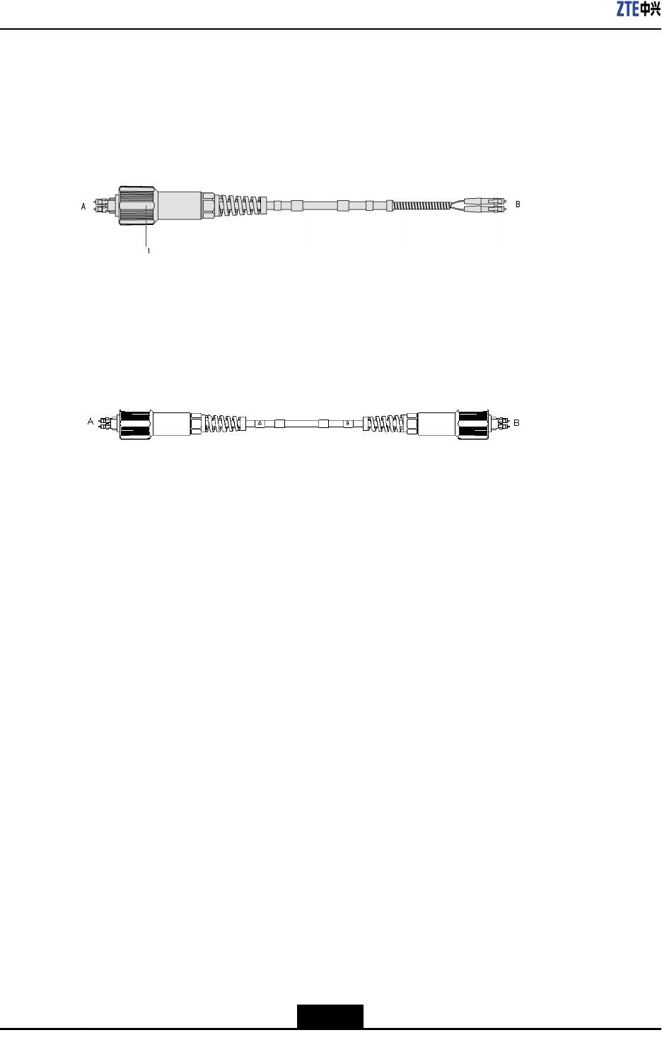
ExternalView
ASingleModeFiber(SMF)cableisusedtoconnecttheZXSDRR8882chassistoaBBU.
EndAismountedwithawaterproofLCconnector,andendBismountedwithanLC
connector,asshowninFigure4-4.
Figure4-4FiberCableforConnectingaBBU
1.Outdoorwaterproof
assembly
AnSMFcablewithbothendsmountedwithawaterproofLCconnectorisusedtoconnect
twoRRUs,asshowninFigure4-5.
Figure4-5FiberCableforCascadingRRUs
SignalDenition
None
Connections
ThecableconnectionbetweenanRRUandaBBUisasfollows:
lEndAisconnectedtoanopticalinterface(OPT1,OPT2,orOPT3)ontheZXSDR
R8882chassis.
lEndBisconnectedtoanappropriateopticalinterfaceoftheBBU.
ThecableconnectionbetweentwocascadedRRUsisasfollows:
lEndAisconnectedtoanopticalinterface(OPT1,OPT2,orOPT3)onaZXSDRR8882
chassis.
lEndBisconnectedtoanopticalinterface(OPT1,OPT2,orOPT3)ontheother
ZXSDRR8882chassis.
4.6ExternalMonitoringCable
Function
TheexternalmonitoringcablesupportstheinteractionofsignalsbetweentheZXSDR
R8882systemandexternaldevices,includingtheinteractionofalarmsignals,
RS485/RS422controlsignals,anddrycontactsignals.
4-4
SJ-20111021104623-003|2012–01–30(R1.1)ZTEProprietaryandCondential
Chapter4ExternalCables
ExternalView
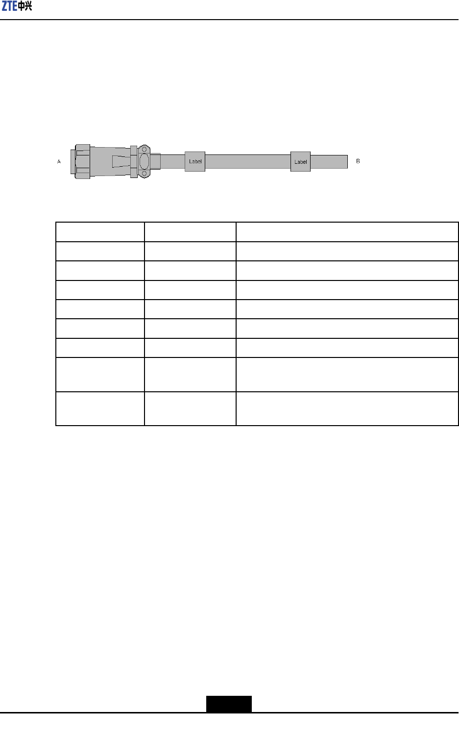
Figure4-6showstheexternalviewoftheexternalmonitoringcable.EndAismounted
withan8-pinroundplug.EndBneedstobemountedwithanappropriateconnectoron
siteaccordingtotheconnectortypeoftheexternaldevicetobeconnected.Thecable
lengthis1.2m.
Figure4-6AppearanceoftheExternalMonitoringCable
SignalDenition
PinNameDenition
PIN1Dry_Node_In1+Drycontactinput,positive
PIN2Dry_Node_In1-Drycontactinput,negative
PIN3Dry_Node_In2+Drycontactinput,positive
PIN4Dry_Node_In2-Drycontactinput,negative
PIN5RS485TX+Full-duplexRS422/RS485TX+(differentialmode)
PIN6RS485TX-Full-duplexRS422/RS485TX-(differentialmode)
PIN7RS485RX+Full-duplexRS422/RS485RX+(differentialmode)or
half-duplexRS485A
PIN8RS485RX-Full-duplexRS422/RS485RX-(differentialmode)or
half-duplexRS485B
Connection
lEndAisconnectedtotheMONinterfaceontheZXSDRR8882chassis.
lEndBisconnectedtoanexternalmonitoringdeviceoradrycontactdevice.
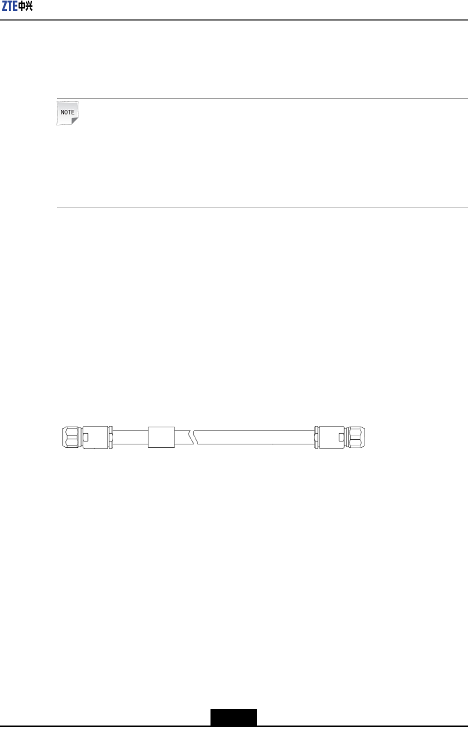
4.7AISGControlCable
Function
TheAISGcontrolcableisusedtosendAISGcontrolsignalstoanRETantennathatis
connectedtotheZXSDRR8882.
ExternalView
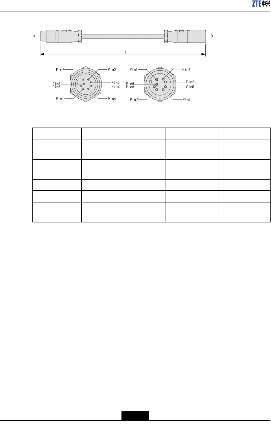
An8-pinaviationplugincompliancewithIEC60130-9-EDismountedonbothendsofthe
AISGcontrolcable,asshowninFigure4-7.
4-5
SJ-20111021104623-003|2012–01–30(R1.1)ZTEProprietaryandCondential
ZXSDRR8882HardwareDescription
Figure4-7AISGControlCable
SignalDenition
NameDenitionPin(EndA)Pin(EndB)
AISG_RS485BRS485signalpositive(RS485B
speciedinAISG)
PIN3PIN1
AISG_RS485ARS485signalnegative(RS485A
speciedinAISG)
PIN5PIN2
AISG_PWRDCpower(output)PIN6PIN3,PIN4
GNDPDCpowerground(output)PIN7PIN5,PIN6
NCNotusedPIN1,PIN2,PIN4,
PIN8
-
Connections
lEndAisconnectedtotheAISGinterfaceontheZXSDRR8882chassis.
lEndBisconnectedtothecontrolinterfaceofanRETantenna.
4-6
SJ-20111021104623-003|2012–01–30(R1.1)ZTEProprietaryandCondential

Figures
Figure1-1AppearanceoftheZXSDRR8882withTwoOpticalPorts........................1-1
Figure1-2AppearanceoftheZXSDRR8882withThreeOpticalPorts.....................1-2
Figure2-1ExternalInterfacesattheBottom(TwoOpticalInterfaces).......................2-1
Figure2-2ExternalInterfaceattheRightSide(TwoOpticalInterfaces)....................2-2
Figure2-3ExternalInterfacesattheBottom(ThreeOpticalInterfaces)....................2-5
Figure2-4ExternalInterfaceattheRightSide(ThreeOpticalInterfaces).................2-5
Figure3-1IndicatorsoftheRRU(TwoOpticalInterfaces).........................................3-1
Figure3-2IndicatorsoftheRRU(ThreeOpticalInterfaces)......................................3-2
Figure4-1AppearanceoftheProtectiveGroundingCable.......................................4-1
Figure4-2AppearanceoftheDCPowerInputCable................................................4-2
Figure4-3AppearanceoftheAntennaCable...........................................................4-3
Figure4-4FiberCableforConnectingaBBU...........................................................4-4
Figure4-5FiberCableforCascadingRRUs.............................................................4-4
Figure4-6AppearanceoftheExternalMonitoringCable..........................................4-5
Figure4-7AISGControlCable.................................................................................4-6
I

Figures
Thispageintentionallyleftblank.

Tables
Table2-1ExternalInterfaceDescription(TwoOpticalInterfaces)..............................2-2
Table2-2ExternalInterfaces....................................................................................2-6
Table3-1IndicatorDescription..................................................................................3-2
III

Tables
Thispageintentionallyleftblank.

Index
A
AISGcontrolcable...............................4-5
antennafeedercable............................4-3
D
DCpowerinputcable...........................4-2
E
externalcables.....................................4-1
externalinterfaces................................2-1
externalmonitoringcable.....................4-4
F
bercable............................................4-3
I
indicators..............................................3-1
P
protectivegroundingcable...................4-1
V

Index
Thispageintentionallyleftblank.

Glossary
AISG
-AntennaInterfaceStandardsGroup
BBU
-BaseBandUnit
DIN
-DeutschesInstitutfürNormung(=GermanInstituteforStandardization)
PCB
-PrintedCircuitBoard
RET
-RemoteElectricalTilt
RF
-RadioFrequency
SMF
-SingleModeFiber
VII