ZTE R8882S8500 ZXSDR R8882 S8500 is Macro Radio Remote Unit User Manual IV
ZTE Corporation ZXSDR R8882 S8500 is Macro Radio Remote Unit IV
ZTE >
Contents
User Manual IV
Chapter3DeviceInstallation
Figure3-9MountingtheDevice
1.Screw2.Lockingshim
Figure3-10SecuringtheDevice
1.Lockingshim2.Screw
–EndofSteps–
3-13
SJ-20111021104623-004|2012–01-30(R1.1)ZTEProprietaryandCondential
ZXSDRR8882HardwareInstallationGuide
3.4Pole-MountedInstallation
3.4.1UsingMountingKit1toMounttheDeviceonaPole
Steps
1.Securetheinstallationassemblies(wallmountingassemblyandpolemounting
piece):Attachthewallmountingassemblytothepolemountingpiecewithfour
M10×35hexagonbolts,asshowninFigure3-11.
Figure3-11AttachingtheWallMountingAssemblytothePoleMountingPiece
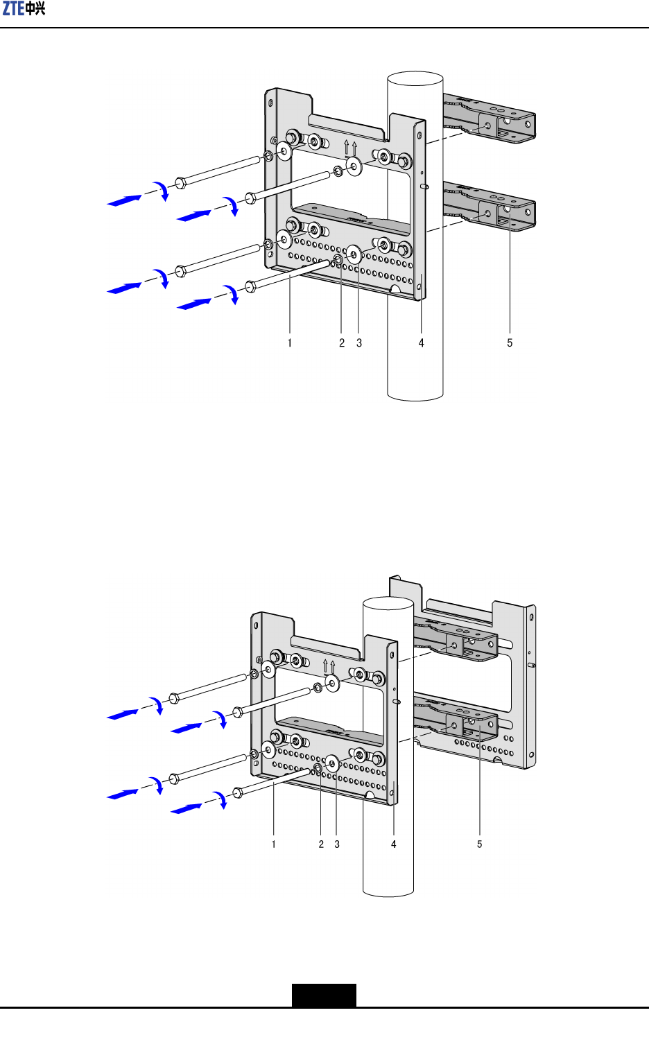
2.Securethepolemountingpieceandinstallationassembly(inasingle-unitscenario):
Securethepolemountingpieceandinstallationassemblyonthepolewithfour
M10×180longbolts,asshowninFigure3-12.
3-14
SJ-20111021104623-004|2012–01-30(R1.1)ZTEProprietaryandCondential
Chapter3DeviceInstallation
Figure3-12SecuringthePoleMountingPiece
1.M10×180longbolts
2.Springwasher
3.Flatwasher
4.Installationassembly
5.Polemountingpiece
3.Securetwosetsofinstallationassembliesbacktoback(indouble-unitandtriple-unit
scenarios):Securetwosetsofinstallationassembliesbacktobackonthepolewith
fourM10×180longbolts,asshowninFigure3-13.
Figure3-13SecuringTwoSetsofInstallationAssembliesBacktoBack
1.M10×180longbolts
2.Springwasher
3.Flatwasher
4.Frontinstallation
assembly
5.Backinstallation
assembly
3-15
SJ-20111021104623-004|2012–01-30(R1.1)ZTEProprietaryandCondential
ZXSDRR8882HardwareInstallationGuide
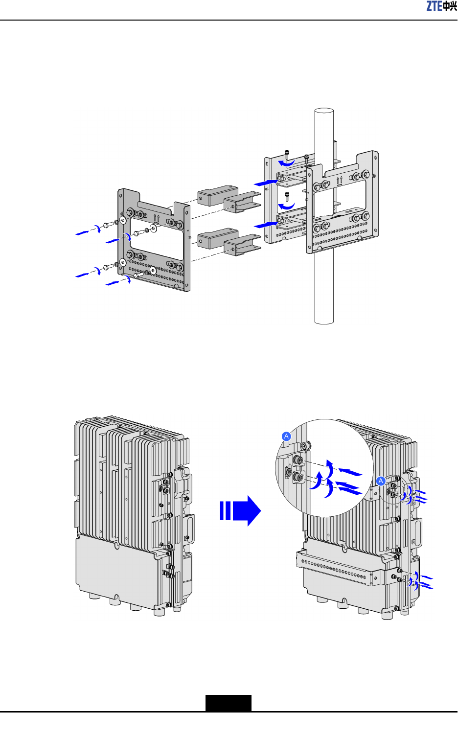
4.Installtheextensionpiecesandwallmountingassembly(inatriple-unitscenario):
Attachtheextensionpiecesandwallmountingassemblytothesideofthepole
mountingassemblieswithfourM6×60Allenscrews,asshowninFigure3-14.
Figure3-14InstallingtheExtensionPiecesandWallMountingAssembly
5.Installdevicehooks(twoU-shapedhooks):Usethe12M16boltsdisassembledfrom
theZXSDRR8882tosecurethetwoU-shapedhookstothebackofthedevice.See
Figure3-15.
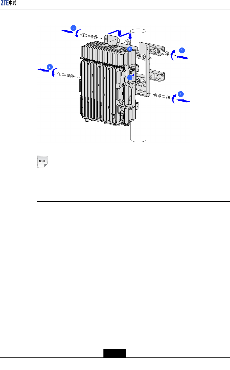
Figure3-15InstallDeviceHooks(TwoU-shapedHooks)
6.Mountandsecurethedevice:HangZXSDRR8882onthehookonthewallmounting
assemblyandsecureZXSDRR8882withfourM6×20Allenscrews,asshowninFigure
3-16.
3-16
SJ-20111021104623-004|2012–01-30(R1.1)ZTEProprietaryandCondential
Chapter3DeviceInstallation
Figure3-16MountingandSecuringtheDevice
Note:
Thisgureshowsthemethodofmountingandsecuringthedeviceinasingle-unit
scenario.Usethesamemethodtomountandsecuredevicesinadouble-unitor
triple-unitscenario.
–EndofSteps–
3.4.2UsingMountingKit2toMounttheDeviceonaPole
Steps
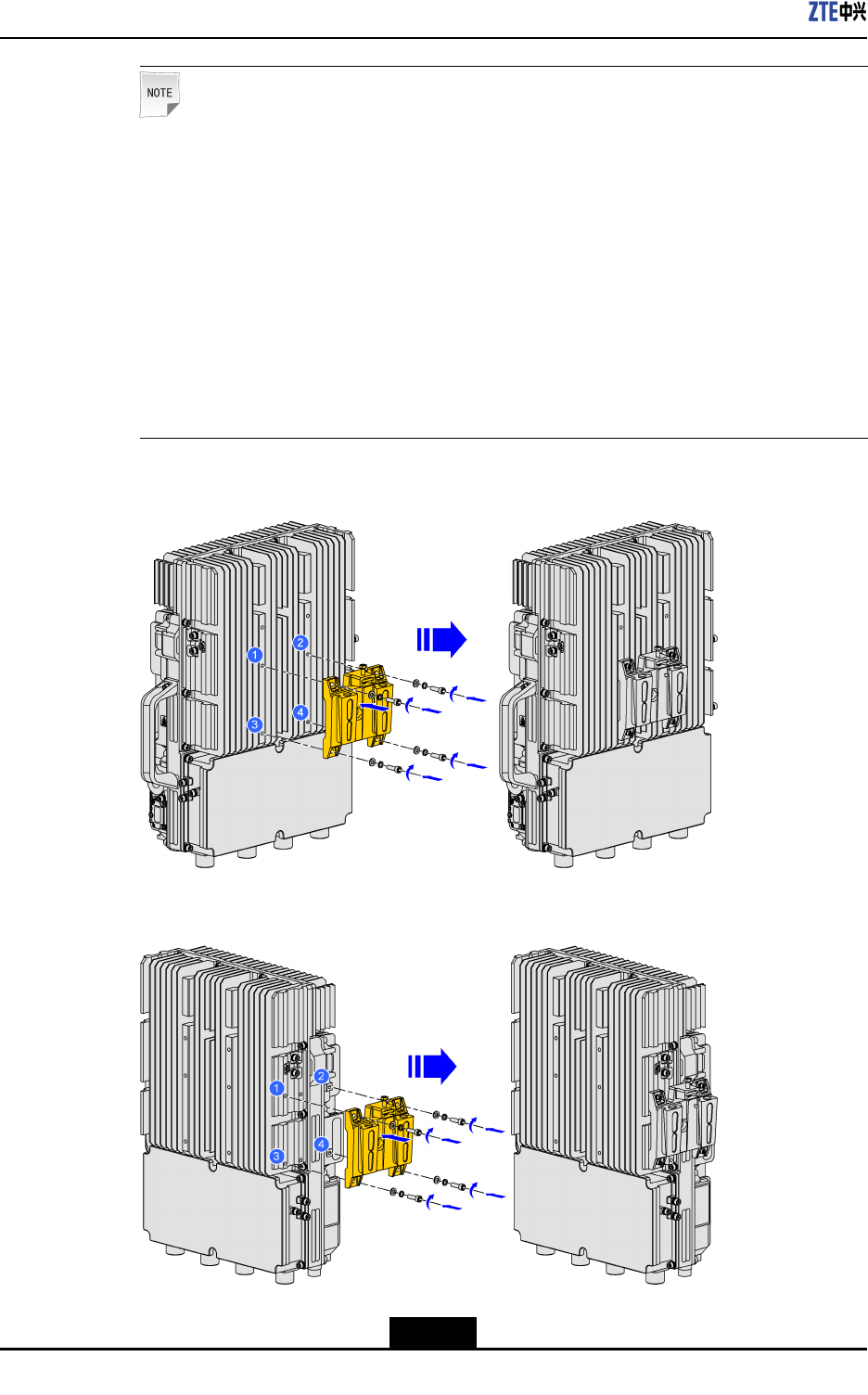
1.InstalltheRRUmountingbase:AttachtheRRUmountingbasetothebackofthe
devicewithfourM6screws,asshowninFigure3-17;attachtheRRUmountingbase
tothesideofthedevicewithfourM6screws,asshowninFigure3-18.
3-17
SJ-20111021104623-004|2012–01-30(R1.1)ZTEProprietaryandCondential
ZXSDRR8882HardwareInstallationGuide
Note:
TheRRUmountingbasecanbeinstalledonthebackorsideofthedevice.
lInasingle-unitscenario,installationpersonnelneedtoinstalloneRRUmounting
baseonthebackofthedevice.
lInadouble-unitscenario,installationpersonnelneedtoinstalloneRRUmounting
baseonthebackofeachdevice.
lInatriple-unitscenario,installationpersonnelneedtoinstalloneRRUmounting
baseonthebackofonedeviceandtwoRRUmountingbasesonthesidesofthe
othertwodevices.
lInaquadro-unitscenario,installationpersonnelneedtoinstallfourRRUmounting
basesonthesidesofthedevice.
Figure3-17InstallingtheRRUMountingBaseontheBackoftheDevice
Figure3-18MountingtheRRUMountingBaseontheSideoftheDevice
3-18
SJ-20111021104623-004|2012–01-30(R1.1)ZTEProprietaryandCondential
Chapter3DeviceInstallation
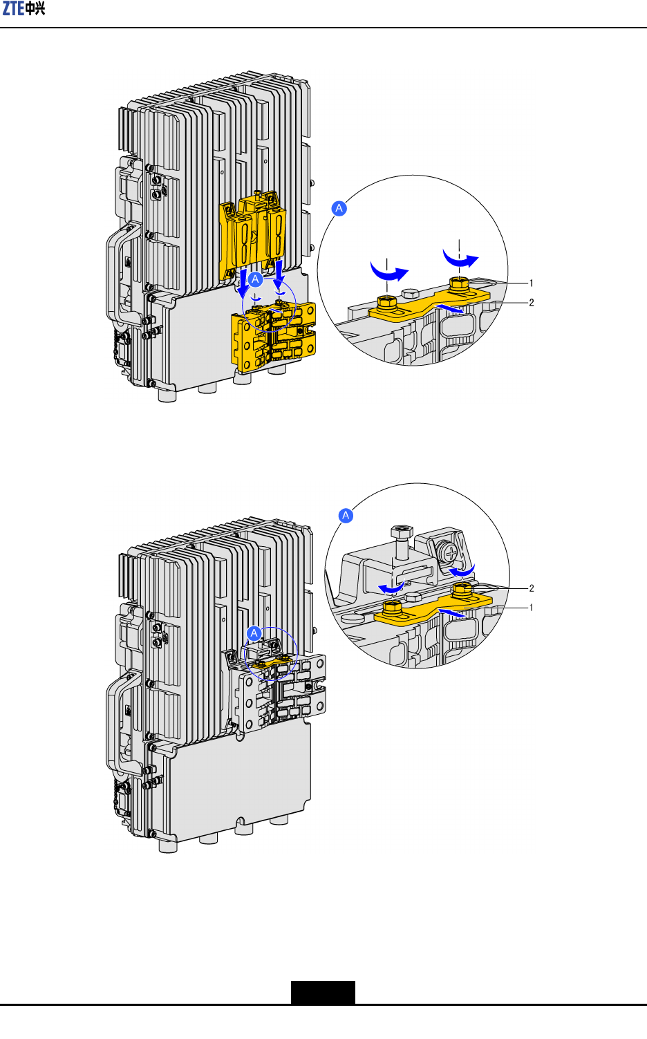
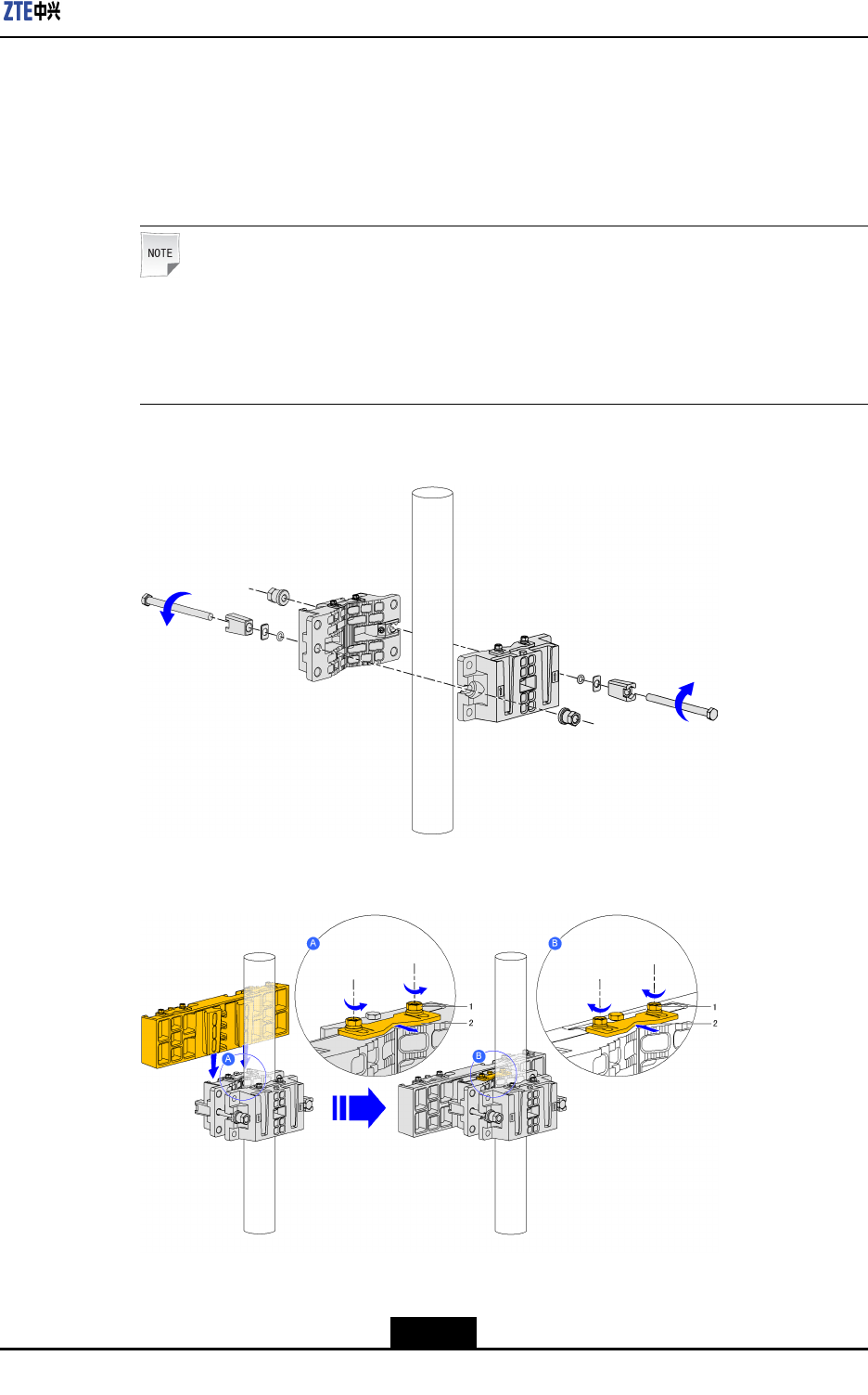
2.Installthepolemountingassembliesandparallelmountingbase:Attachtwopole
mountingassembliesonapoleandtightenthetwofasteningbolts,asshowninFigure
3-19;hangtheparallelmountingbaseononeofthepolemountingassemblies,push
thelockingshimonthepolemountingassemblyuntilitlockstheparallelmounting
base,andthentightenthetwoscrewsonthelockingshim,asshowninFigure3-20.
Note:
Inasingle-unitordouble-unitscenario,onlythepolemountingassembliesneedtobe
installed.Inatriple-unitorquadro-unitscenario,thepolemountingassembliesand
oneortwoparallelmountingbasesneedtobeinstalled.
Figure3-19SecuringthePoleMountingAssembly
Figure3-20InstallingtheParallelMountingBase
1.Screw2.Lockingshim
3-19
SJ-20111021104623-004|2012–01-30(R1.1)ZTEProprietaryandCondential
ZXSDRR8882HardwareInstallationGuide
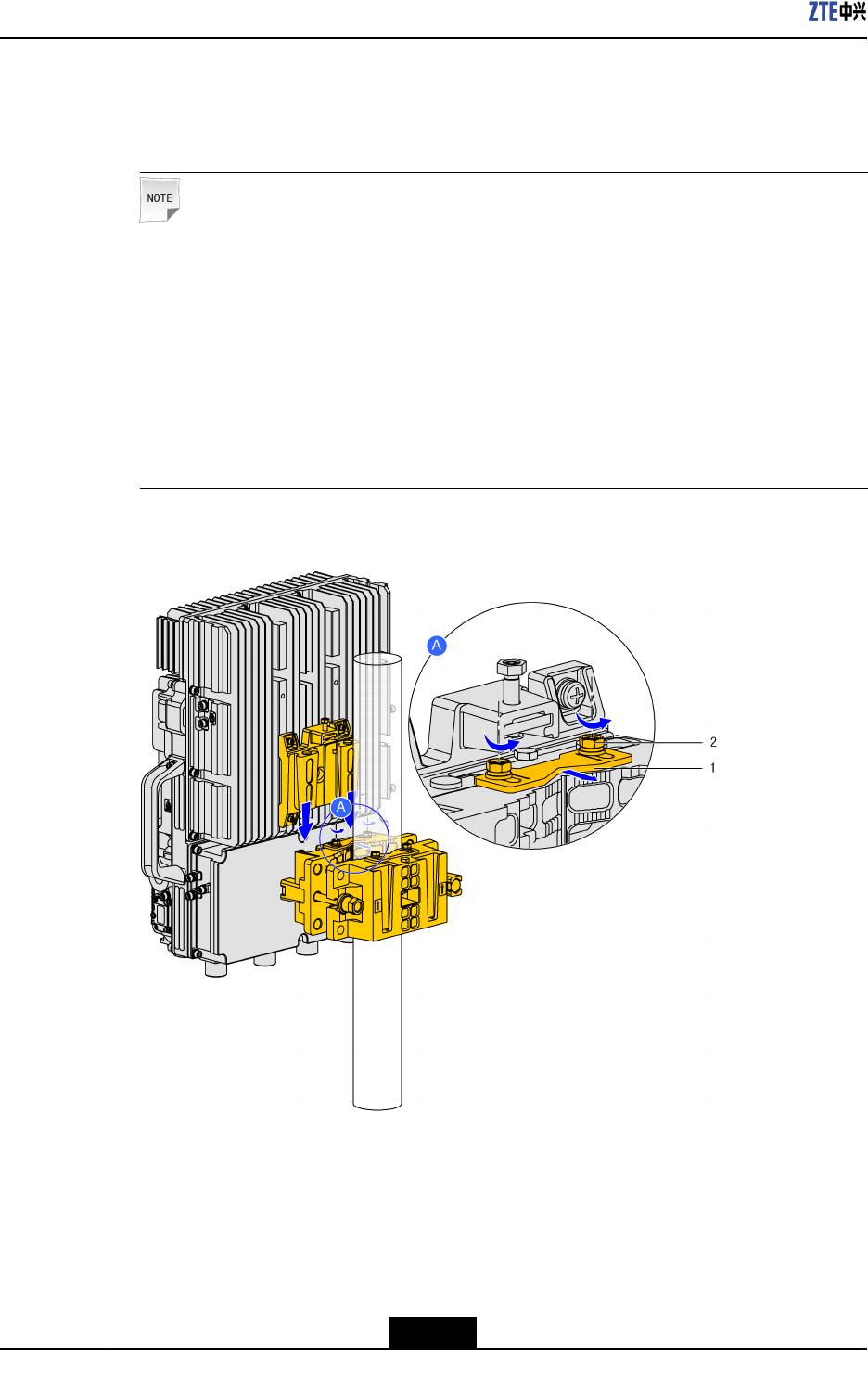
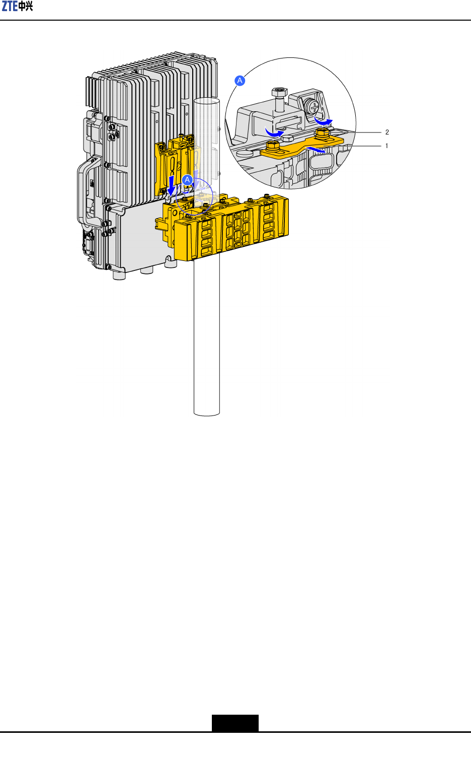
3.MounttheRRU:Mountthedevicewithaback-mountedRRUbaseonthepole
mountingassembly,asshowninFigure3-21andFigure3-22;mountthedevicewith
aside-mountedRRUbaseontheparallelmountingbase,asshowninFigure3-23.
Note:
TheRRUcanbefront-mountedandside-mounted.
lInasingle-unitordouble-unitscenario,thedeviceisfront-mountedtothepole
mountingassembly.
lInatriple-unitscenario,onedeviceisfront-mountedtothepolemounting
assemblyandtheothertwodevicesareside-mountedtotheparallelmounting
base.
lInaquadro-unitscenario,thedevicesareside-mountedtotheparallelmounting
base.
Figure3-21Front-MountingtheDevice(Single-UnitSolution/Double-UnitSolution)
1.Lockingshim2.Screw
3-20
SJ-20111021104623-004|2012–01-30(R1.1)ZTEProprietaryandCondential
Chapter3DeviceInstallation
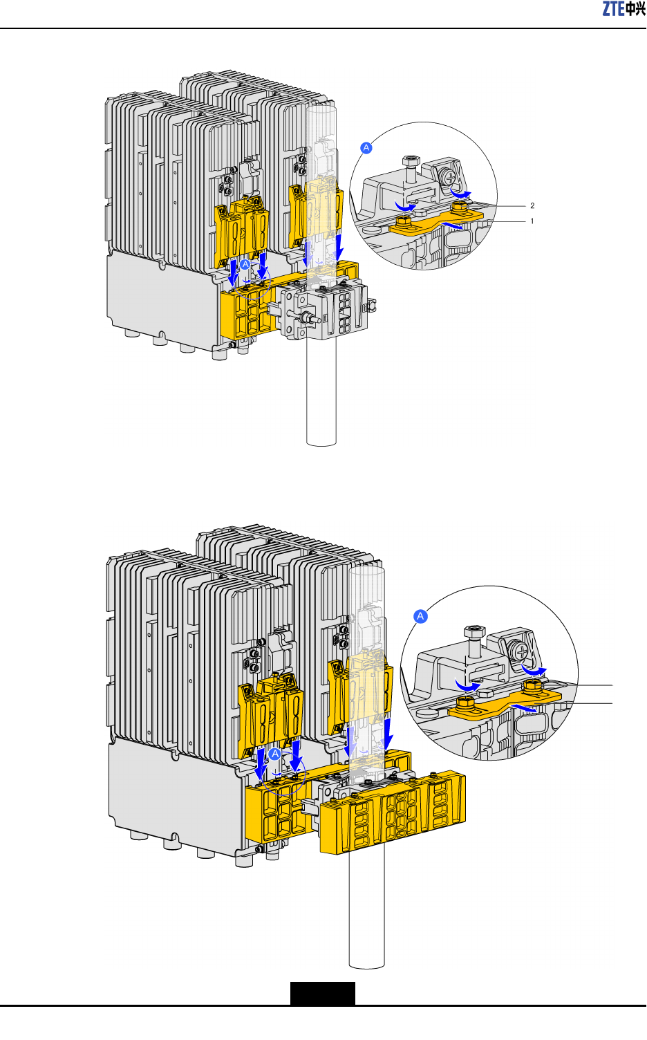
Figure3-22Front-MountingtheDevice(Triple-UnitSolution)
1.Lockingshim2.Screw
3-21
SJ-20111021104623-004|2012–01-30(R1.1)ZTEProprietaryandCondential
ZXSDRR8882HardwareInstallationGuide
Figure3-23Side-MountingtheDevice(Triple-UnitSolution)
1.Lockingshim2.Screw
Figure3-24Side-MountingtheDevice(Quadro-UnitSolution)
3-22
SJ-20111021104623-004|2012–01-30(R1.1)ZTEProprietaryandCondential
Chapter3DeviceInstallation
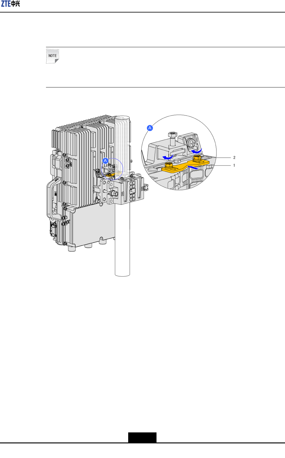
4.Securethedevice:PushthelockingshimtolocktheRRUmountingbaseandtighten
thetwoscrewsonthelockingshim,asshowninFigure3-25.
Note:
Inanyscenario,themethodofsecuringthedeviceisthesame.
Figure3-25SecuringtheDevice
1.Lockingshim2.Screw
–EndofSteps–
3.5PortalFrame-MountedInstallation
3.5.1UsingMountingKit1toMounttheDeviceonaPortalFrame
Steps
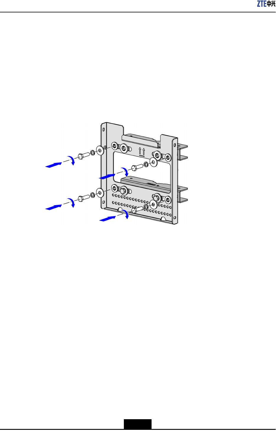
1.Installthemountingpanel:Securethewallmountingassemblyatanappropriate
positiononthe
portalframewithfourM8boltandnutassemblies,asshowninFigure
3-26.
3-23
SJ-20111021104623-004|2012–01-30(R1.1)ZTEProprietaryandCondential
ZXSDRR8882HardwareInstallationGuide
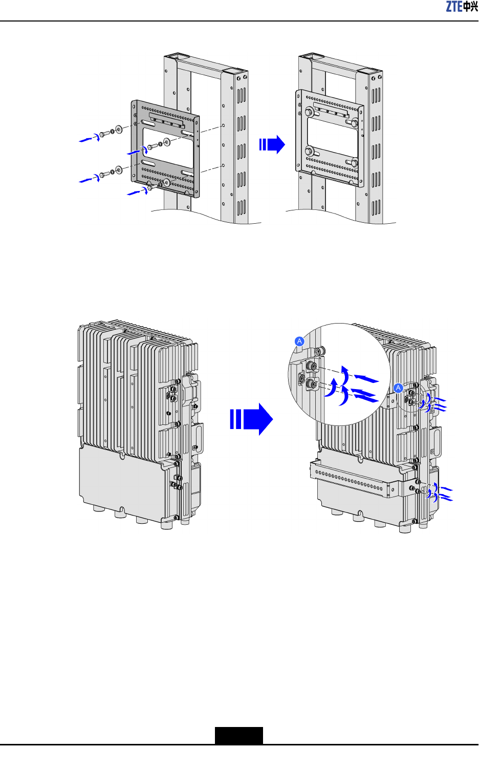
Figure3-26InstallingtheUniversalSheet-MetalKit
2.Installdevicehooks(twoU-shapedhooks):Usethe12M16boltsdisassembledfrom
theZXSDRR8882tosecurethetwoU-shapedhookstothebackofthedevice.See
Figure3-27.
Figure3-27InstallDeviceHooks(TwoU-shapedHooks)
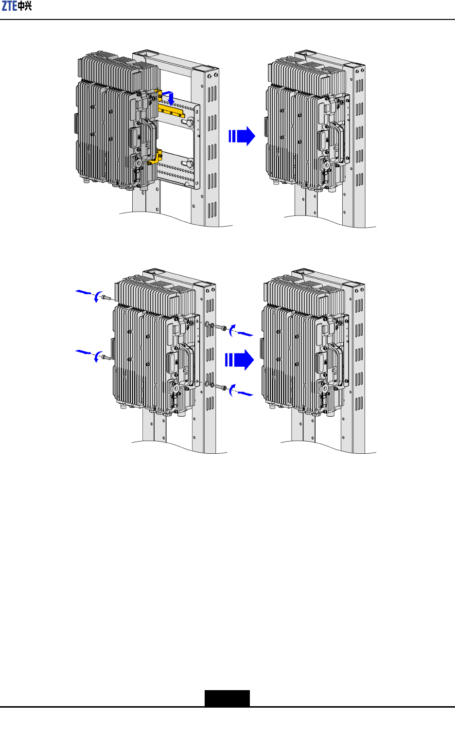
3.Mountandsecurethedevice:Hangthedeviceonthehookonthewallmounting
assemblyandsecurethedevicewithfourM6Allenbolts,asshowninFigure3-28and
Figure3-29.
3-24
SJ-20111021104623-004|2012–01-30(R1.1)ZTEProprietaryandCondential
Chapter3DeviceInstallation
Figure3-28MountingtheDevice
Figure3-29SecuringtheDevice
–EndofSteps–
3.5.2UsingMountingKit2toMounttheDeviceonaPortalFrame
Steps
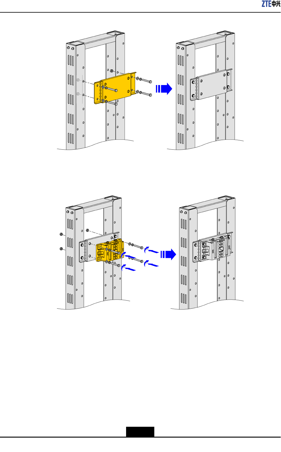
1.Installtheadaptorplateandpolemountingclamp:
a.AttachtheadaptorplatetotheportalframeandsecureitwithfourM8boltandnut
assemblies,asshowninFigure3-30.
3-25
SJ-20111021104623-004|2012–01-30(R1.1)ZTEProprietaryandCondential
ZXSDRR8882HardwareInstallationGuide
Figure3-30MountingtheAdaptorPlate
b.AttachthepolemountingclamptotheadaptorplateandsecureitwithfourM12
boltandnutassemblies,asshowninFigure3-31.
Figure3-31MountingthePoleMountingClamp
2.InstalltheRRUmountingbaseonthebackofthedevice:Fortheoperation,referto
UsingMountingKit2toMounttheDeviceonaWall.
3.MountandsecurethedeviceontheRRUmountingbase:Fortheoperation,referto
UsingMountingKit1toMounttheDeviceonaWall.
–EndofSteps–
3.6InstallingtheProtectionShade
Prerequisite
ZXSDRR8882hasbeeninstalled.
3-26
SJ-20111021104623-004|2012–01-30(R1.1)ZTEProprietaryandCondential
Chapter3DeviceInstallation
Context
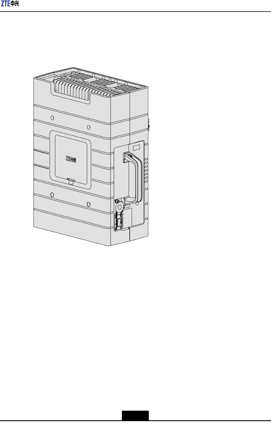
Therearetwotypesof
protectionshades.Thenewtypehasalreadybeenassembled
beforedeliverytocustomer,asshowninFigure3-32.
Figure3-32NewTypeofProtectionShade
Thissectiondescribeshowtoinstalltheoldtypeofprotectionshade.
Steps
1.Alignthefourmountingholesontheprotectionshadewiththefourmountingholes
onbothsidesofZXSDRR8882,andthensecuretheprotectionshadewithM5×16
crossrecessedheadscrewassembliesandM5×20hexagonsocketcapheadscrew
assemblies,asshowninFigure3-33.
3-27
SJ-20111021104623-004|2012–01-30(R1.1)ZTEProprietaryandCondential

ZXSDRR8882HardwareInstallationGuide
Figure3-33InstallingtheProtectionShade
1.Protectionshade
2.M5×16crossrecessed
headscrewassembly
3.Lockingposition
4.M5×20hexagon
socketcapheadscrew
assembly
5.ZXSDRR8882
–EndofSteps–
3-28
SJ-20111021104623-004|2012–01-30(R1.1)ZTEProprietaryandCondential
Chapter4
Cabling
TableofContents
FlowofConnectingExternalCables...........................................................................4-1
ConnectingtheProtectiveGroundingCable...............................................................4-2
ConnectingtheDCPowerCable................................................................................4-3
ConnectingtheOpticalFiber......................................................................................4-7
ConnectingtheMonitoringCable................................................................................4-9
ConnectingtheAISGCable......................................................................................4-11
ConnectingtheFeederJumper................................................................................4-12
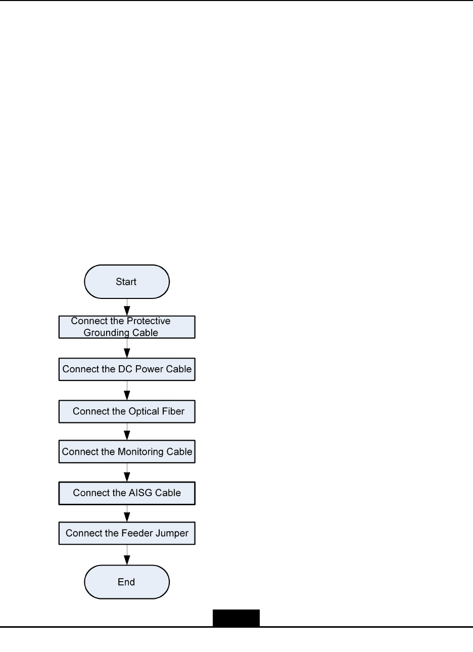
4.1FlowofConnectingExternalCables
Figure4-1showstherecommendedowofconnectingexternalcables.Theowcanbe
adjustedasrequiredbytheon-siteconditions.
Figure4-1FlowchartofConnectingExternalCables
4-1
SJ-20111021104623-004|2012–01-30(R1.1)ZTEProprietaryandCondential
ZXSDRR8882HardwareInstallationGuide
Note:
Fortheappearancesandlinesequencedenitionsofalltheinterfacecables,refertothe
ZXSDRR8882HardwareDescription.
4.2ConnectingtheProtectiveGroundingCable
Steps
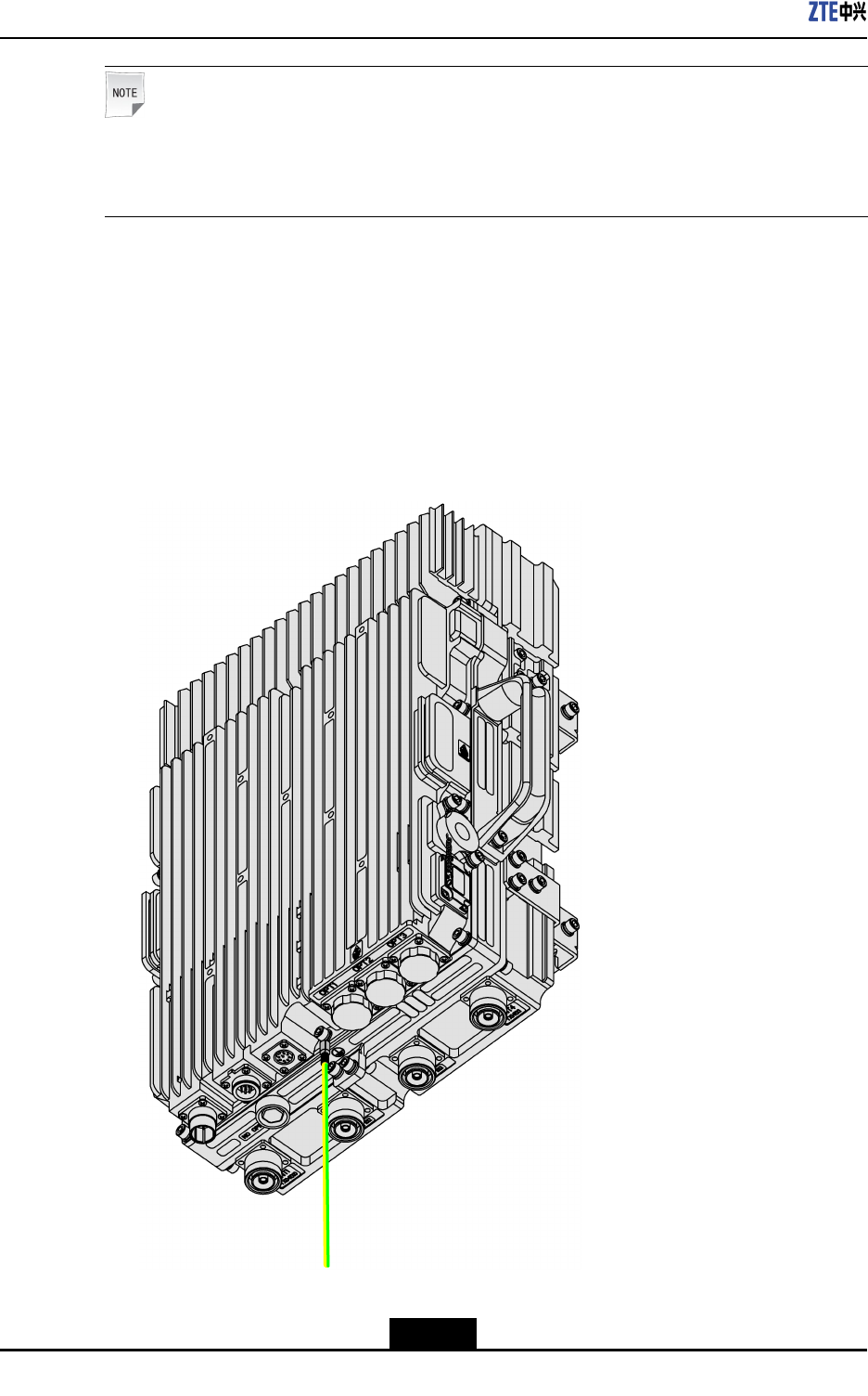
1.Putonecoppertubularlugoftheprotectivegroundingcableononegroundingboltof
ZXSDRR8882andtightenthegroundingbolt,asshowninFigure4-2.
Figure4-2ConnectingtheProtectiveGroundingCable
4-2
SJ-20111021104623-004|2012–01-30(R1.1)ZTEProprietaryandCondential
Chapter4Cabling
2.Puttheothercoppertubularlugoftheprotectivegroundingcableononegrounding
pointofthepoweradapterboxsuchasthePIMDC.
3.Connecttheothergroundingpointofthepoweradapterboxtothenearestgrounding
barandsecureitwithabolt.
4.Attachappropriatelabelsatbothendsofthecable.
5.Applygreasetothecoppertubularlugsatbothendsofthecable.
–EndofSteps–
4.3ConnectingtheDCPowerCable
Context
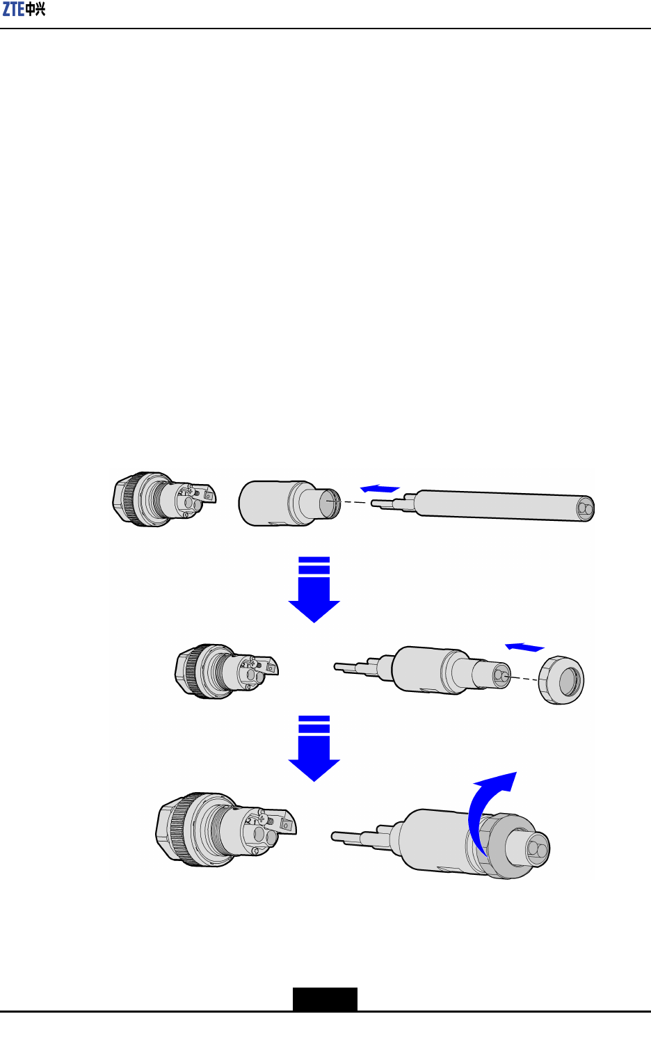
Thepowercableshouldbeconnectedwiththeconnectorbeforethepowercableis
installed.
1.Insertthepowercableintothesealingcomponent,andthenstripofftheprotective
layerofthepowercableasrequired,asillustratedinFigure4-3.
Figure4-3InsertingthePowerCableIntotheSealingComponent
4-3
SJ-20111021104623-004|2012–01-30(R1.1)ZTEProprietaryandCondential
ZXSDRR8882HardwareInstallationGuide
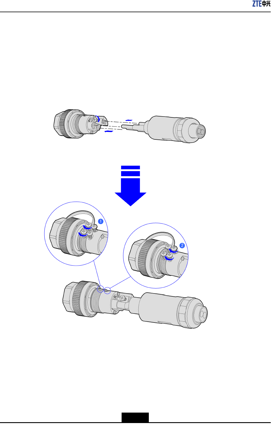
2.Insertthepowercableintothecorrespondingholeattheterminal,andtightenitwith
screws,asillustratedinFigure4-4.
a.Securethescrewaateachterminalwithascrewdriver,andpullthepowercable
slightlytocheckwhetheritisproperlysecured.
b.Securethescrew2withthescrewdriver.
c.Threadtheshieldinglayerthatistwistedintoastrandintotheholeontheshielding
unit,andthensecureitwithscrews.
Figure4-4InstallingthePowerCableIntotheTerminalHole
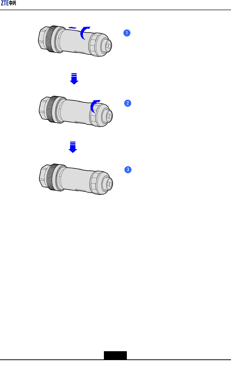
3.Securethesealingcomponentclockwisetotheconnector,andthenxthepowercable
bytighteningtherearnut,asillustratedinFigure4-5.
4-4
SJ-20111021104623-004|2012–01-30(R1.1)ZTEProprietaryandCondential
Chapter4Cabling
Figure4-5FixingthePowerCable
Steps
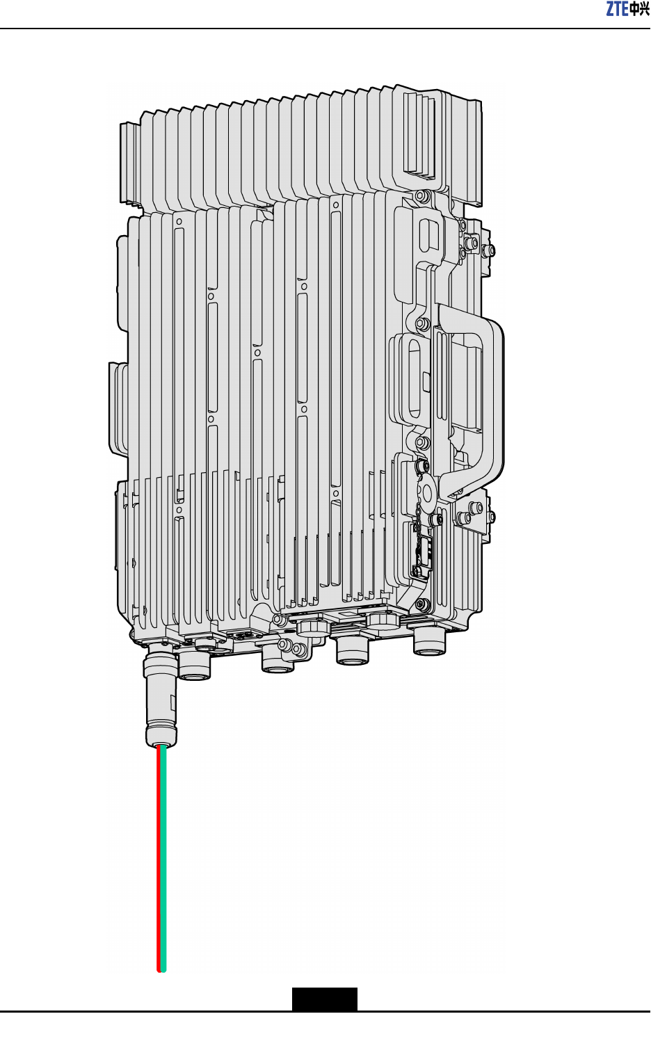
1.ConnectendAoftheDCpowercabletothePWRinterfaceofZXSDRR8882,as
showninFigure4-6.
4-5
SJ-20111021104623-004|2012–01-30(R1.1)ZTEProprietaryandCondential
ZXSDRR8882HardwareInstallationGuide
Figure4-6ConnectingtheDCPowerCable
4-6
SJ-20111021104623-004|2012–01-30(R1.1)ZTEProprietaryandCondential

Chapter4Cabling
2.StriptheprotectivelayeratendBoftheDCpowercableandconnectthecorewires
tothepowersupplydeviceaccordingtotheircolors.
Note:
IfusingthePIMDC,installationpersonnelneedtoconnectthecorewirestothePIMDC
accordingtothecolorsofthecorewiresbeforeconnectingthePIMDCtotheexternal
powersupply.
Connectthebluecorewiretothe-48Vterminal,connecttheblackcorewiretothe
-48VRTNterminal.
3.WaterproofbothconnectorsoftheDCpowercable.
4.AttachappropriatelabelsatbothendsoftheDCpowercable.
5.TieuptheDCpowercable.
–EndofSteps–
4.4ConnectingtheOpticalFiber
Steps
1.
Attachappropriatelabelsatbothendsoftheopticalber.
2.Removetheprotectivecapoftheopticalber,removetheprotectivesleeve,and
removethewhiteprotectivecapofthecore.
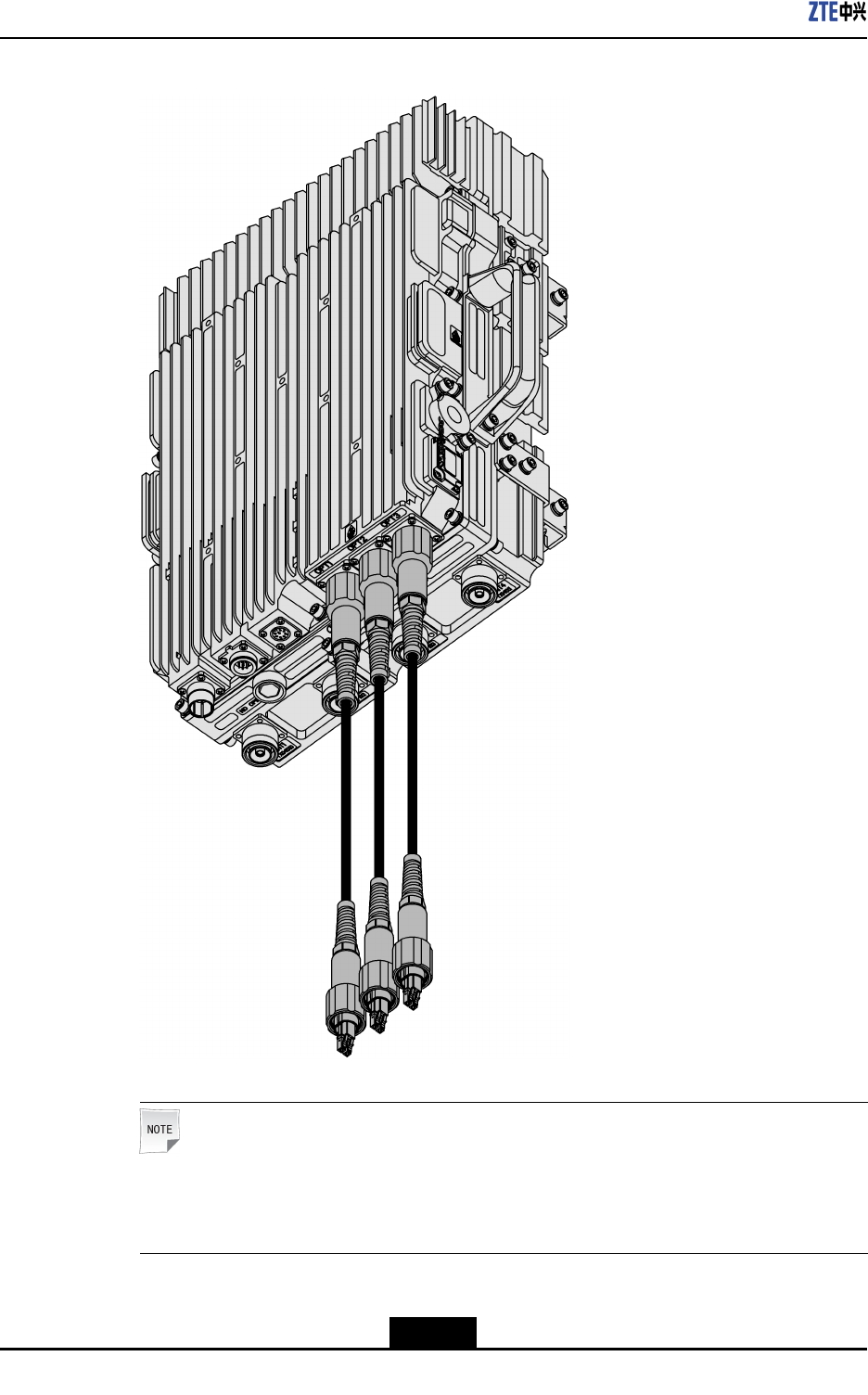
3.AdjustthesidewithacolormarkatendAoftheopticalber,insertendAoftheoptical
berintothebasebandRFopticalinterface(OPT1/2/3)ofthedevice,andthentighten
theprotectivesleeve,asshowninFigure4-7.
4-7
SJ-20111021104623-004|2012–01-30(R1.1)ZTEProprietaryandCondential
ZXSDRR8882HardwareInstallationGuide
Figure4-7ConnectingtheOpticalFiber
Note:
Ifthedevicehastwoopticalports,theninstalltwoopticalbersinopticalports1and
2.
4-8
SJ-20111021104623-004|2012–01-30(R1.1)ZTEProprietaryandCondential

Chapter4Cabling
4.WhentheopticalberconnectsthedevicetoaBBU,connecttheDLCoptical
connectoratendBoftheopticalbertotheopticalconnectoroftheBBU;whenthe
opticalbercascadesthedevicetoanotherZXSDRR8882,connectendBofthe
opticalbertothebasebandRFopticalinterface(OPT1/2/3)oftheotherZXSDR
R8882.
5.Tightentheoutdoorsealingassemblyoftheopticalberandwaterprooftheconnector.
–EndofSteps–
4.5ConnectingtheMonitoringCable
Steps
1.ConnectendAofthemonitoring(MON)cabletotheAISGinterfaceofZXSDRR8882,
asshowninFigure4-8.
4-9
SJ-20111021104623-004|2012–01-30(R1.1)ZTEProprietaryandCondential