ZTE R8882S8500 ZXSDR R8882 S8500 is Macro Radio Remote Unit User Manual V
ZTE Corporation ZXSDR R8882 S8500 is Macro Radio Remote Unit V
ZTE >
Contents
User Manual V
ZXSDRR8882HardwareInstallationGuide
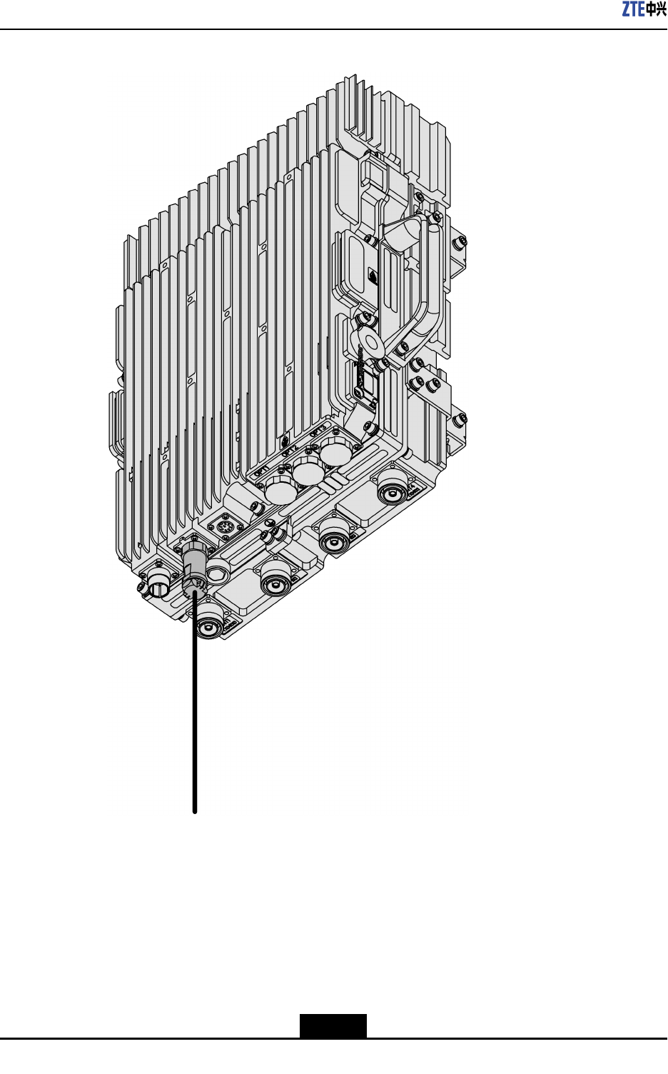
Figure4-8ConnectingtheMonitoringCable
2.ConnectendBoftheMONcabletoanexternalmonitoringdeviceordrycontact.
–EndofSteps–
4-10
SJ-20111021104623-004|2012–01-30(R1.1)ZTEProprietaryandCondential
Chapter4Cabling
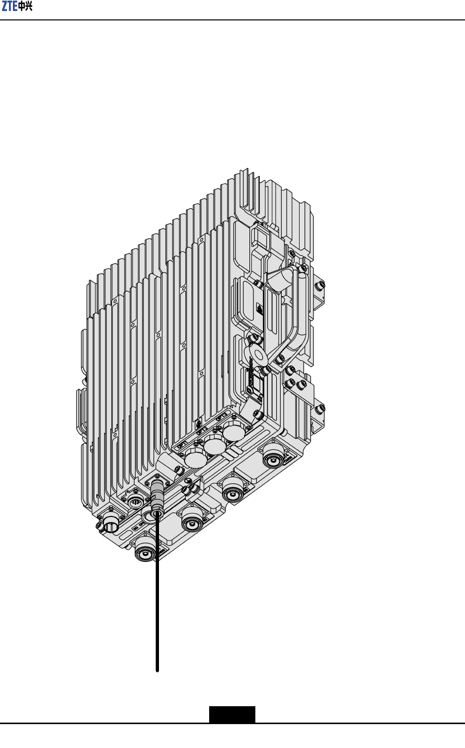
4.6ConnectingtheAISGCable
Steps
1.ConnectendAoftheAntennaInterfaceStandardsGroup(AISG)cabletothe
commissioninginterface(AISG)ofZXSDRR8882,andtightenthescrew,asshown
inFigure4-9.
Figure4-9ConnectingtheAISGCable
4-11
SJ-20111021104623-004|2012–01-30(R1.1)ZTEProprietaryandCondential

ZXSDRR8882HardwareInstallationGuide
2.ConnectendBoftheAISGcabletothecontrolinterfaceofanelectricallytuneddevice
andtightenthescrew.
3.WaterproofbothconnectorsoftheAISGcable.
–EndofSteps–
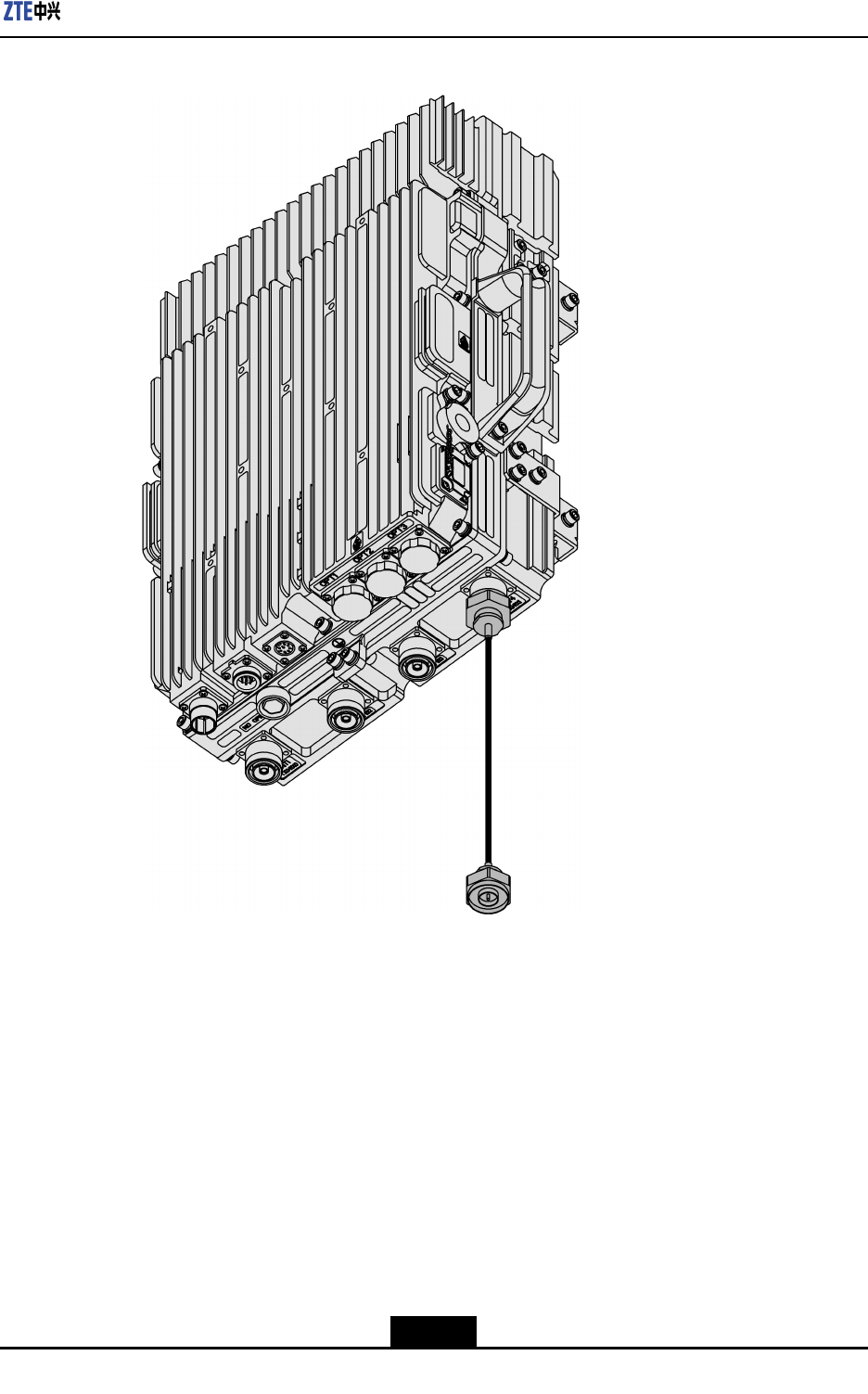
4.7ConnectingtheFeederJumper
Context
TheRFjumperisusedtoconnectthefeedertothefeederinterfaceofZXSDRR8882.
Thejumpershouldbeconnectedafterthemainfeederisconnected.
Normally,useanished2m1/2"jumperastheRFjumper,ormakeajumperasrequired
bytheon-sitecondition,refertoZXC10BSSBCDMA2000BaseStationSystemCable
PreparationManualforPreparinginstructions.
Steps
1.ConnecttheDINmaleconnectoroftheRFjumpertotheRFantennainterfaceofthe
device,asshowninFigure4-10.
4-12
SJ-20111021104623-004|2012–01-30(R1.1)ZTEProprietaryandCondential
Chapter4Cabling
Figure4-10ConnectingtheFeederJumper
2.ConnecttheDINmaleconnectoroftheRFjumpertotheDINfemaleconnectorofthe
mainfeeder.
3.Waterproofbothconnectorsofthefeederjumper.
–EndofSteps–
4-13
SJ-20111021104623-004|2012–01-30(R1.1)ZTEProprietaryandCondential

ZXSDRR8882HardwareInstallationGuide
Thispageintentionallyleftblank.
4-14
SJ-20111021104623-004|2012–01-30(R1.1)ZTEProprietaryandCondential

Chapter5
Post-InstallationCheck
CheckingtheDeviceInstallation
ItemTaskRemark
Makesurethatthedeviceinstallation
positionisinlinewiththedesign
drawing.
Makesurethatthedeviceisinstalled
rmlyandmeetstheshockproof
requirements.
Makesurethatthedeviationofthe
deviceinhorizonandverticalisless
than3mm.
Makesurethatthedevicesurface
iscleanandtidy,thepaintonthe
surfaceisintact,andallpartsofthe
deviceareinplaceandundamaged.
Makesurethattheidentiersof
thedevicearecorrect,clear,and
complete.
Makesurethatallscrewsofthe
deviceareproperlytightened.
Makesurethattheatwashers
andspringwashersareinstalledin
correctorder.
Checkingthedeviceinstallation
Makesurethattheunused
connectorcapsaretightened.
CheckingtheCableConnection
ItemTaskRemark
Makesurethatallcablesarelaid
straightwithoutuctuationandskew
andwithoutcrosslinesandying
lines.
Makesurethatallcablesturn
smoothlyandtheexternalofeach
Verifyingthatcablingmeetsthe
specications
5-1
SJ-20111021104623-004|2012–01-30(R1.1)ZTEProprietaryandCondential

ZXSDRR8882HardwareInstallationGuide
ItemTaskRemark
curveisverticallyorhorizontally
straight.
Makesurethatallcablesare
labelledatthebothends,theuse
ofeachcableisdescribed,andthe
contentsinthelabelsatbothends
arethesame.
Makesurethattheconnectionis
solid,ingoodcontact,plugged
correctlyandwithoutbreakand
bend.
Makesurethatcabletiesareevenly
spacedanduniformlyandproperly
tied.Makesurethatunnecessary
sectionofacabletieiscutoff.
Makesurethattheterminalsof
allcablesareinstalledwithat
washersandspringwashersand
waterproofmeasuresaretakento
cableconnectorsandgroundingkit.
Makesurethatthepowercableand
groundingcablearelaidseparately
fromothercables.Makesurethat
thepowercableandsignalcables
arelaidondifferentcableracks
whentherearemultiplecableracks.
Makesurethatthehorizontal
distancebetweenthecablesismore
than100mmwhenthepowercable
andsignalcablearelaidinparallel
onasamecablerack.
Makesurethatthedistancebetween
thecablesisnolessthan300mm
whentheACpowercable,DC
powercable,andsignalcable(such
astheantennafeeder)arelaidin
parallel.
Makesurethatthepowercableand
groundingcablearemadeofthe
entirecablewithoutjoints.
Checkingthepowercableand
groundingcableconnections
5-2
SJ-20111021104623-004|2012–01-30(R1.1)ZTEProprietaryandCondential

Chapter5Post-InstallationCheck
ItemTaskRemark
Makesurethatonlyonedeviceis
connectedtoeachgroundingpoint
onthegroundingbar.
Makesurethatthepowercableand
groundingcablearenotcoiledand
theunnecessarysectioniscutoff.
Makesurethatthecoppertubular
lugsatbothendsofthepowerline
orgroundingcableareweldedor
crimpedrmly.
Makesurethatthegroundingpath
isasshortaspossible.
Makesurethatthebarewireandlug
handleontheconnectionterminal
arewrappedwiththeinsulatingtape
ortubedintheheat-shrinktube.
Makesurethattheminimalturning
radiusofanoutdooropticalcable
is90mmandtheminimalturning
radiusofanindooropticalcableis
30mm.
Makesurethattheopticalberis
notintertwined.
Makesurethatthecablingtransition
issmoothandthedistancebetween
everytwocabletiesislessthan0.5
m.
Makesurethatthelabelsatboth
endsoftheopticalberareclear.
Makesurethattheconnectorsat
bothendsoftheopticalberare
tightened.
Checkingtheopticalber
connection
Makesurethatthebercableis
undamaged.
5-3
SJ-20111021104623-004|2012–01-30(R1.1)ZTEProprietaryandCondential

ZXSDRR8882HardwareInstallationGuide
ItemTaskRemark
MakesurethatthefeederVSWRis
lessthan1.5.
Makesurethattheconnectors
atbothendsofthefeederare
tightened.
MakesurethattheDIN-typeand
N-typeconnectorsareconnected
correctly.
Makesurethattheantennaand
jumperareconnectedcorrectly
andthejumperandfeederare
connectedcorrectly.
Makesurethatthewater-trapcurve
ismadebeforethecableisledinto
theequipmentroom,andmake
surethatthelowestpointofthe
water-trapcurveis10cm–20cm
lowerthantheloweredgeofthe
entranceinthefeederwindow.
Makesurethatthefeederwindowis
sealedwithreproofmaterial.
Checkingtheantennafeeder
connection
Makesurethattheunusedantenna
feedercableconnectorsarecovered
bycapsortightenedbydummy
loads.
5-4
SJ-20111021104623-004|2012–01-30(R1.1)ZTEProprietaryandCondential

Chapter6
ConcludingRoutines
Beforeleavingthesite,completethefollowing:
lCleanupthesiteandremoveobjectslikewrappingpaperandcablepieces.
lDisposeofwastematerialaccordingtolocalregulations.
lCompletethesiteinstallationreport.
lHandovertheSiteInstallationDocumentationtothepersonresponsibleforthesite.
lIfthesiteisinoperation,contacttheOMCorNMCtoinformthattheinstallationis
completed.
lLockalldoorsandgatestothesite.
6-1
SJ-20111021104623-004|2012–01-30(R1.1)ZTEProprietaryandCondential

ZXSDRR8882HardwareInstallationGuide
Thispageintentionallyleftblank.
6-2
SJ-20111021104623-004|2012–01-30(R1.1)ZTEProprietaryandCondential
AppendixA
WaterproofingOutdoor
Connectors
Prerequisite
Afterthewholeantennafeedersystemhasbeeninstalledandtested,makesurethatthe
outdoorjumpersandfeederconnectorsmustbewaterproof.
Context
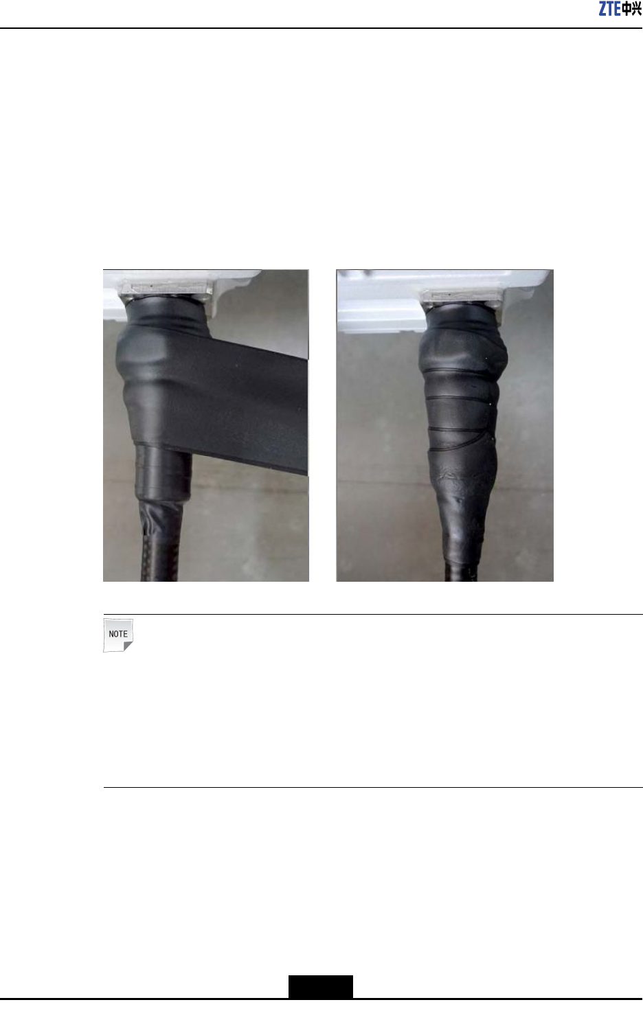
Waterproongoutdoorconnectorsisa“1+3+3”process,thatis,wrappingonelayerof
PVCinsulatingtape,threelayersofwaterproofinsulatingtape,andthreelayersofPVC
insulatingtapearoundaconnector.
ThePVCinsulatingtapeisusedtopreventconnectorsfromdamage,ageing,andwater
ingress.
Steps
1.Cleanthefeederconnectorandfeedergroundingclip.
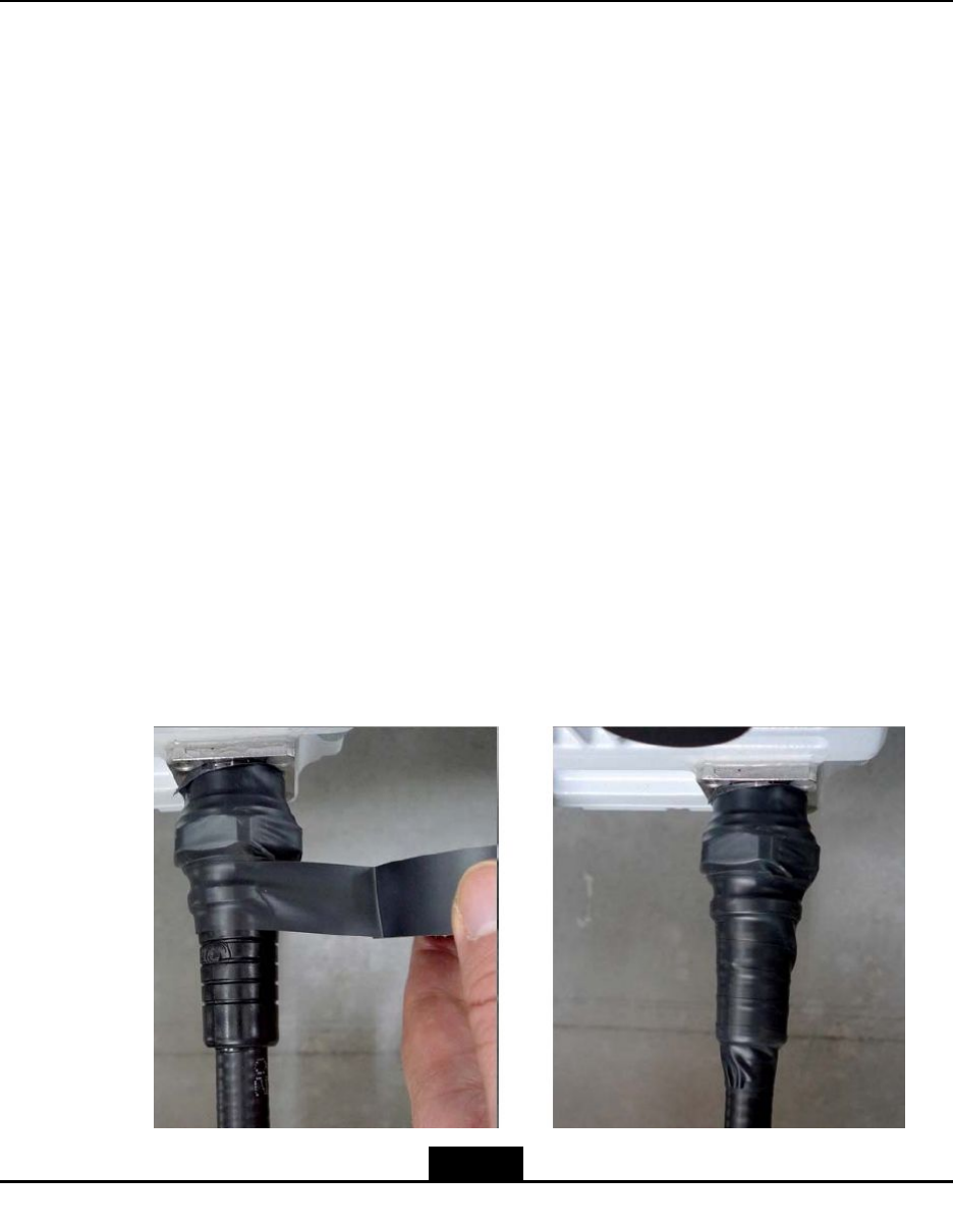
2.WrapalayerofPVCinsulatingtapearoundtheconnector.
Afterconnectingtheconnectorproperly,wrapalayerofelectricalinsulatingtapefor
oneandahalfcircleinthedirectionoftighteningtheconnector,asshowninFigure
A-1.Theexceededwrappinglengthis10mm.Duringwrapping,donotoverstretch
theinsulatingtape.
FigureA-1WrappingOneLayerofInsulatingTape
A-1
SJ-20111021104623-004|2012–01-30(R1.1)ZTEProprietaryandCondential
ZXSDRR8882HardwareInstallationGuide
3.WrapthreelayersofwaterproofinsulatingtapearoundthePVCtape.
Duringwrapping,stretchtheself-adhesivetapetwotimestheoriginallength.Foreach
connector,useabout50cmwaterprooftapetowrapthreelayers,asshowninFigure
A-2.
Thewrappingdirectionmustbethesameasthatoftighteningafeederconnector.
Thispreventsthefeederconnectorfrombeingdisconnectedduringwrapping.After
that,gripandpinchthewrappedtaperepeatedlytoensurethatthetapeandfeederor
feederconnectoraresecurelyadhered.
FigureA-2WrappingThreeLayersofWaterproofTape
Note:
Wraptherstlayerofinsulatingtapefrombottomtotop,thesecondlayerfromtopto
bottom,andthethirdlayerfrombottomtotop.Theupperlayercovers1/3ofthenext
layerinlength.Thisensuresthatthefeederorfeederconnectoriswaterproof.During
wrapping,donotcutoffthetape.Thewrappinglengthmustbe20mmlongerthan
thatofthefeederconnector.
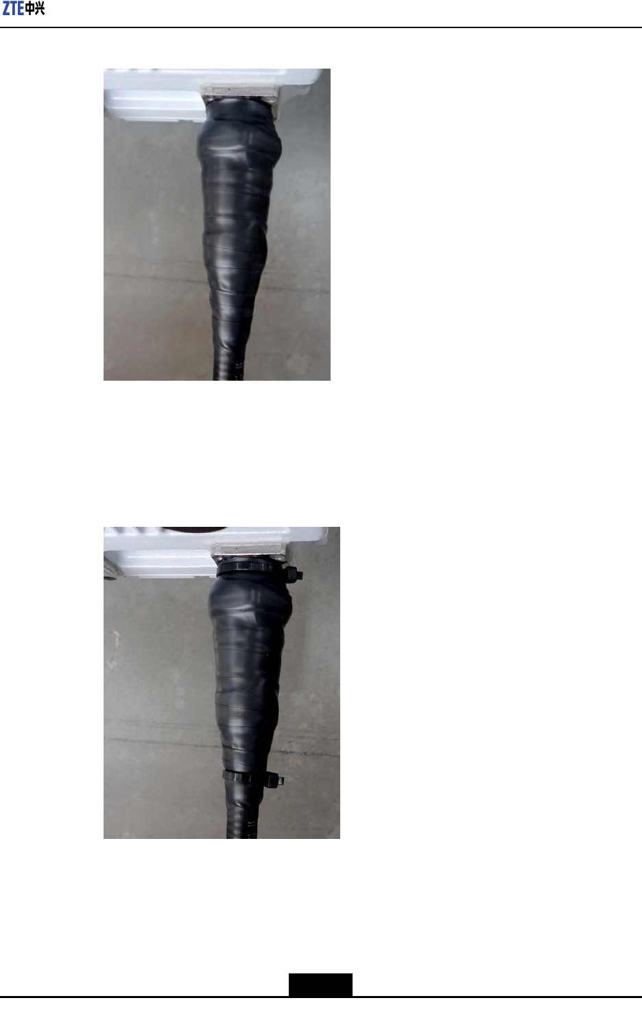
4.WrapthreelayersofUVresistancetape.
Thewrappingdirectionmustbethesameasthatoftighteningafeederconnector.The
upper-layertapecovers1/2thebottom-layertapeinlength.Thewrappinglengthof
theUVresistancetapemustbe10mmlongerthanthatofthewaterprooftape.Wrap
threelayers.Afterthat,gripandpinchboththeUVresistancetapeandwaterproof
tapetoensurethattheyaresecurelyadhered,asshowninFigureA-3.
A-2
SJ-20111021104623-004|2012–01-30(R1.1)ZTEProprietaryandCondential
AppendixAWaterproongOutdoorConnectors
FigureA-3WrapThreeLayersofUVResistanceTape
5.Fastenbothendsofthetape.
UseblackUVresistancecabletiestobundlebothendsofthetape,asshownin
FigureA-4.Cutofftheexceededcabletiesandreserveabout3mmforexpansionin
high-temperatureweather.
FigureA-4FixingBothEnds
–EndofSteps–
A-3
SJ-20111021104623-004|2012–01-30(R1.1)ZTEProprietaryandCondential

ZXSDRR8882HardwareInstallationGuide
Thispageintentionallyleftblank.
A-4
SJ-20111021104623-004|2012–01-30(R1.1)ZTEProprietaryandCondential

AppendixB
LabelingSpecifications
ZTECorporationusesindoorlabelsandoutdoorlabels.
lOutdoorlabelsarehangtagsthataredeliveredwiththedevice.
lIndoorlabelsaretheselfadhesivepaper-printedlabelsthatmayneedtobeproduced
atsiteifnecessary.
Labelsmustmeetthefollowingrequirements:
lThespecialpasterofZTECorporationmustbeusedforpaperlabels.
lContentsonrackrowlabelsandcolumnlabelsshouldmeettheengineeringdesign
requirements.
lBoardsshouldnotbelabeledandidentiersonaboardshouldnotbealtered.
lAlllabelsshouldbeattachedtofacethesamedirection.Thesidethatindicates
wherethecableisconnectedtoshouldfaceupwardortowardstheoperationand
maintenancepositionfortheconvenienceofbeingread.
lAllcablessuchasthepowercable,groundingcable,transmissioncable,andfeeder
shouldbelabeledatbothends.
lForopticalbers,networkcables,andtrunkcables,anindoorlabelshouldbepasted
20mmawayfromtheconnectoratbothendseach.
lOutdoorlabelsshouldbesecuredwithcabletiesatthesameheightanddirection.
B-1
SJ-20111021104623-004|2012–01-30(R1.1)ZTEProprietaryandCondential

ZXSDRR8882HardwareInstallationGuide
Thispageintentionallyleftblank.
B-2
SJ-20111021104623-004|2012–01-30(R1.1)ZTEProprietaryandCondential
AppendixC
AssemblingthePortalFrame
Steps
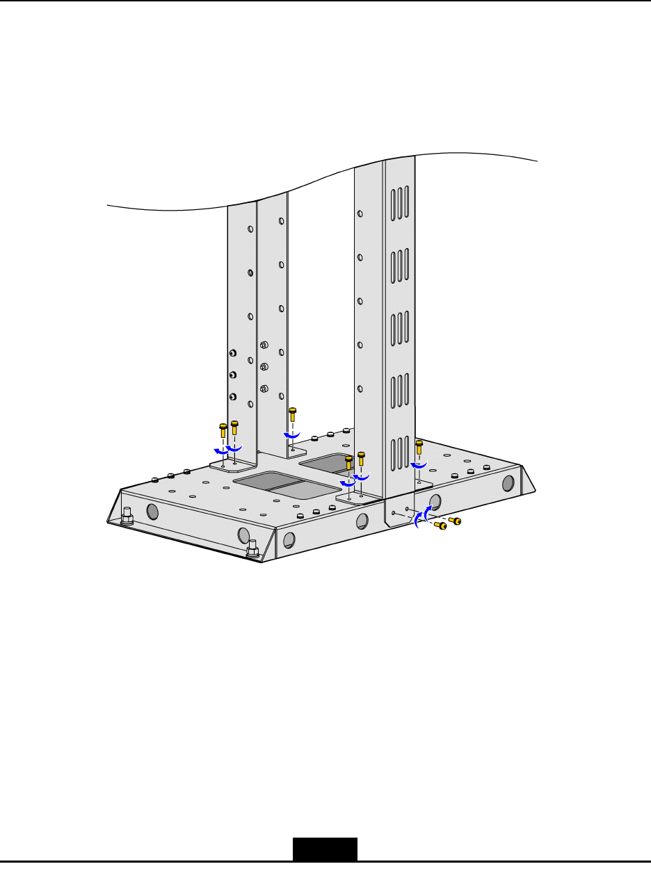
1.Assembletheuprightpostsandbaseplate:Securetheuprightpostsonthebaseplate
withM5×16screws,asshowninFigureC-1.
FigureC-1AssemblingtheUprightPostsandBasePlate
2.Securethecoverplatebetweentheuprightposts:Securethecoverplatebetweenthe
uprightpostswithM5×16screws,asshowninFigureC-2.
C-1
SJ-20111021104623-004|2012–01-30(R1.1)ZTEProprietaryandCondential
ZXSDRR8882HardwareInstallationGuide
FigureC-2SecuringtheCoverPlateBetweentheUprightPosts
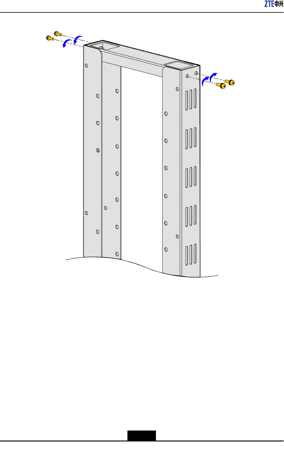
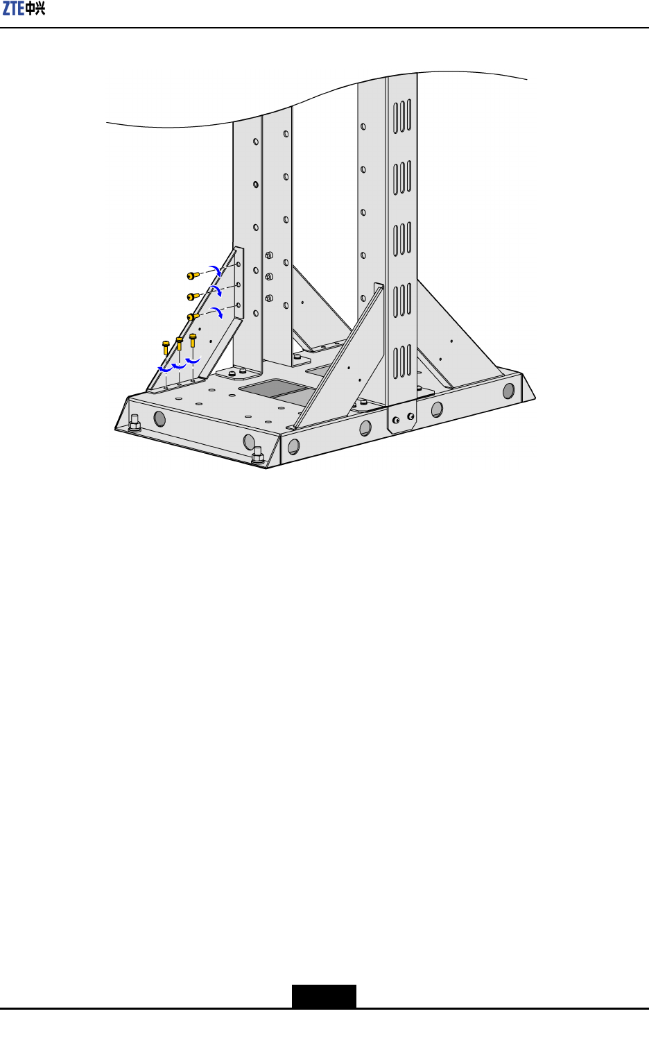
3.Assemblethesidesupports:SecurethesidesupportswithM5×16screws,asshown
inFigureC-3.
C-2
SJ-20111021104623-004|2012–01-30(R1.1)ZTEProprietaryandCondential
AppendixCAssemblingthePortalFrame
FigureC-3InstallingtheSideSupports
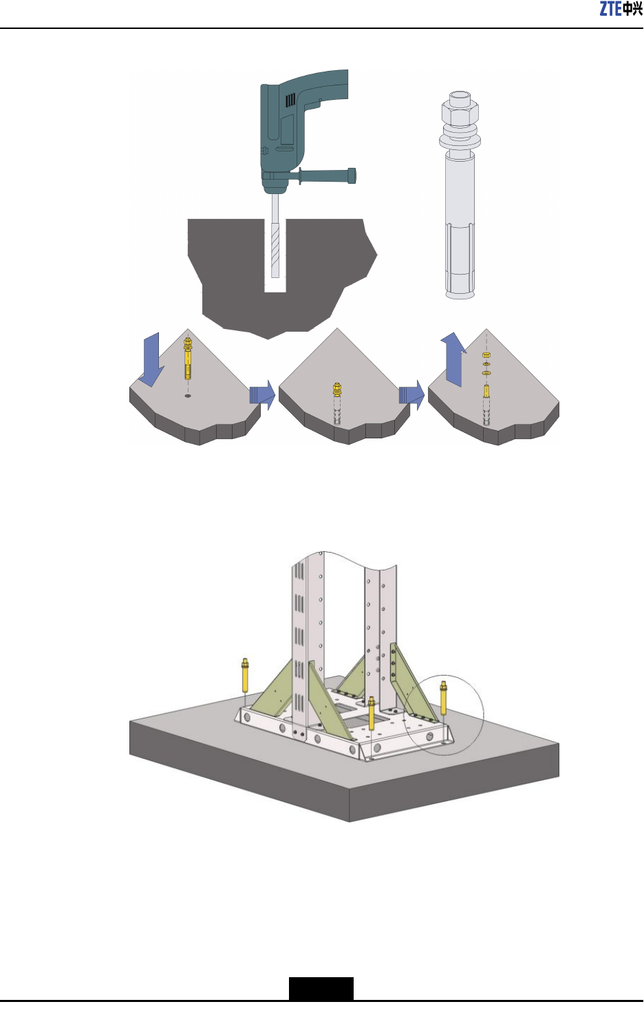
4.Drillholesandtightentheexpansionbolts/screws:
a.Usethedrillingtemplateandmarkthedrillingpositionswithamarker.
b.Drillholesatthemarkeddrillingpositionsbyusinganelectricpercussiondrill(Ф12
drillbit),andtightentheexpansionbolts/screws,asshowninFigureC-4.Usea
vacuumcleanertocleanthedustwhendrillingholes.
C-3
SJ-20111021104623-004|2012–01-30(R1.1)ZTEProprietaryandCondential
ZXSDRR8882HardwareInstallationGuide
FigureC-4InstallingtheExpansionBolts
c.Ifinstallingtheportalframeonacementoor,secureitwithM10×100expansion
screws,asshowninFigureC-5.
FigureC-5SecuringthePortalFrameonaCementFloor
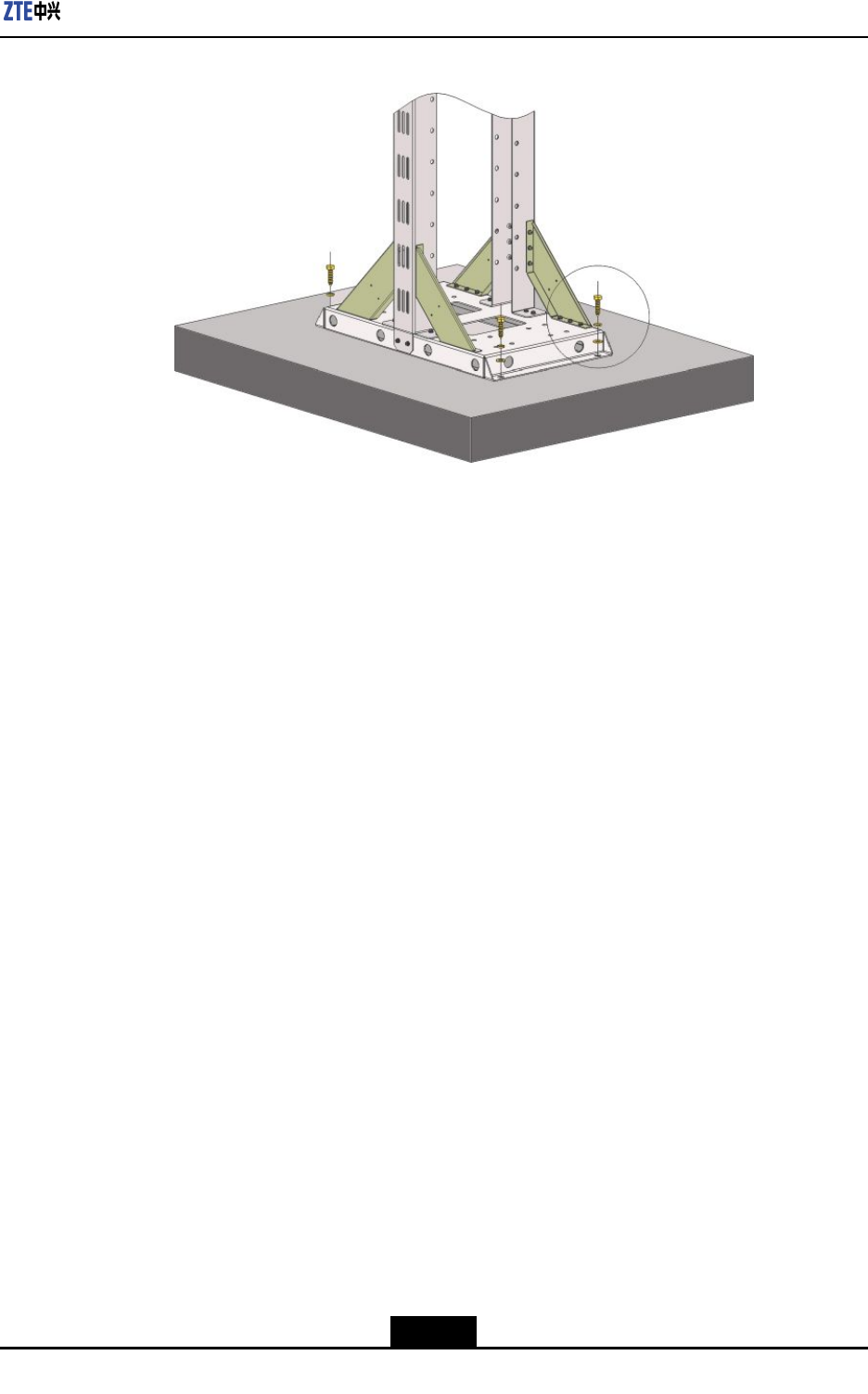
d.Ifinstallingtheportalframeinashelter,secureitwithM10×40tappingscrews,
asshowninFigureC-6.
C-4
SJ-20111021104623-004|2012–01-30(R1.1)ZTEProprietaryandCondential
AppendixCAssemblingthePortalFrame
FigureC-6SecuringthePortalFrameinaShelter
–EndofSteps–
C-5
SJ-20111021104623-004|2012–01-30(R1.1)ZTEProprietaryandCondential

ZXSDRR8882HardwareInstallationGuide
Thispageintentionallyleftblank.
C-6
SJ-20111021104623-004|2012–01-30(R1.1)ZTEProprietaryandCondential

Figures
Figure1-1ZXSDRR8882.........................................................................................1-1
Figure1-2RecommendedSpaceforInstallingZXSDRR8882(Unit:mm)................
1-4
Figure1-3MinimumSpaceforInstallingZXSDRR8882(Unit:mm).........................1-5
Figure1-4FlowchartofInstallingZXSDRR8882......................................................1-8
Figure2-1PIMDCAppearance.................................................................................2-1
Figure2-2SecuringthePIMDCMountingBaseontheFrontoftheDevice...............2-2
Figure2-3SecuringthePIMDContheFrontoftheDevice.......................................2-2
Figure2-4SecuringthePIMDCMountingBaseontheSideoftheDevice................2-3
Figure2-5SecuringthePIMDContheSideoftheDevice........................................
2-3
Figure3-1DrillingPositions......................................................................................
3-7
Figure3-2SecuringtheWallMountingAssembly.....................................................3-8
Figure3-3InstallDeviceHooks(TwoU-shapedHooks)............................................
3-9
Figure3-4MountingtheDeviceontheWallMountingAssembly..............................3-9
Figure3-5SecuringtheDevice...............................................................................3-10
Figure3-6DrillingPositions....................................................................................
3-11
Figure3-7SecuringtheWallMountingAssembly...................................................
3-12
Figure3-8InstallingtheRRUMountingBaseontheBackoftheDevice.................3-12
Figure3-9MountingtheDevice..............................................................................
3-13
Figure3-10SecuringtheDevice.............................................................................3-13
Figure3-11AttachingtheWallMountingAssemblytothePoleMounting
Piece....................................................................................................
3-14
Figure3-12SecuringthePoleMountingPiece.......................................................3-15
Figure3-13SecuringTwoSetsofInstallationAssembliesBacktoBack.................
3-15
Figure3-14InstallingtheExtensionPiecesandWallMountingAssembly...............3-16
Figure3-15InstallDeviceHooks(TwoU-shapedHooks)........................................
3-16
Figure3-16MountingandSecuringtheDevice.......................................................
3-17
Figure3-17InstallingtheRRUMountingBaseontheBackoftheDevice...............
3-18
Figure3-18MountingtheRRUMountingBaseontheSideoftheDevice...............3-18
Figure3-19SecuringthePoleMountingAssembly.................................................3-19
Figure3-20InstallingtheParallelMountingBase...................................................3-19
Figure3-21Front-MountingtheDevice(Single-UnitSolution/Double-Unit
Solution)...............................................................................................3-20
I

ZXSDRR8882HardwareInstallationGuide
Figure3-22Front-MountingtheDevice(Triple-UnitSolution)..................................3-21
Figure3-23Side-MountingtheDevice(Triple-UnitSolution)...................................
3-22
Figure3-24Side-MountingtheDevice(Quadro-UnitSolution)................................3-22
Figure3-25SecuringtheDevice.............................................................................3-23
Figure3-26InstallingtheUniversalSheet-MetalKit................................................3-24
Figure3-27InstallDeviceHooks(TwoU-shapedHooks)........................................3-24
Figure3-28MountingtheDevice............................................................................
3-25
Figure3-29SecuringtheDevice.............................................................................3-25
Figure3-30MountingtheAdaptorPlate..................................................................3-26
Figure3-31MountingthePoleMountingClamp.....................................................3-26
Figure3-32NewTypeofProtectionShade.............................................................3-27
Figure3-33InstallingtheProtectionShade.............................................................3-28
Figure4-1FlowchartofConnectingExternalCables.................................................4-1
Figure4-2ConnectingtheProtectiveGroundingCable.............................................
4-2
Figure4-3InsertingthePowerCableIntotheSealingComponent...........................
4-3
Figure4-4InstallingthePowerCableIntotheTerminalHole....................................4-4
Figure4-5FixingthePowerCable............................................................................
4-5
Figure4-6ConnectingtheDCPowerCable.............................................................4-6
Figure4-7ConnectingtheOpticalFiber....................................................................
4-8
Figure4-8ConnectingtheMonitoringCable...........................................................
4-10
Figure4-9ConnectingtheAISGCable...................................................................
4-11
Figure4-10ConnectingtheFeederJumper............................................................4-13
FigureA-1WrappingOneLayerofInsulatingTape...................................................A-1
FigureA-2WrappingThreeLayersofWaterproofT ape.............................................A-2
FigureA-3WrapThreeLayersofUVResistanceTape.............................................A-3
FigureA-4FixingBothEnds.....................................................................................A-3
FigureC-1AssemblingtheUprightPostsandBasePlate........................................
C-1
FigureC-2SecuringtheCoverPlateBetweentheUprightPosts.............................
C-2
FigureC-3InstallingtheSideSupports....................................................................
C-3
FigureC-4InstallingtheExpansionBolts.................................................................C-4
FigureC-5SecuringthePortalFrameonaCementFloor........................................C-4
FigureC-6SecuringthePortalFrameinaShelter...................................................C-5
II

Tables
Table1-1ZTEPartsandEquipmentListforaRRU..................................................1-2
Table1-2T oolsandMetersList.................................................................................
1-3
Table3-1InstallationPositionsSupportedbytheInstallationAssembliesof
ZXSDRR8882.........................................................................................
3-1
Table3-2InstallationAssemblyofMountingKit1(Wall-Mounted).............................3-2
Table3-3InstallationAssembliesofMountingKit2(Wall-Mounted)..........................
3-3
Table3-4InstallationAssembliesofMountingKit1(Pole-Mounted)..........................3-3
Table3-5InstallationAssembliesofMountingKit2(Pole-Mounted)..........................3-4
Table3-6InstallationAssembliesoftheMountingKit1(Portal
Frame-Mounted)......................................................................................3-5
Table3-7InstallationAssembliesofMountingKit2(PortalFrame-Mounted)............3-6
III

Tables
Thispageintentionallyleftblank.

Index
A
Acceptance..........................................
1-7
appearance..........................................
1-1
C
Cabling.................................................
4-1
ConcludingRoutines............................
6-1
ConnectingtheDCPowerCable..........4-5
ConnectingtheOpticalFiber................4-7
CountingGoods...................................
1-5
D
Delivery................................................
1-7
E
EnvironmentInspection........................1-2
H
Handover.............................................
1-7
I
Inspection.............................................
1-7
InstallationAssemblies.........................
3-2
InstallationFlow...................................
1-7
InstallationOverview............................
1-1
installationpositions.............................3-1
L
LabelingSpecications.........................
B-1
M
MaterielDescription..............................
1-2
Meters..................................................1-2
MounttheDeviceonaWall..................
3-7
MountingKit1....................................
3-14
MountingKit2....................................3-17
P
PIMDC.................................................
2-1
pole....................................................
3-14
portalframe........................................3-23
Post-InstallationCheck.........................5-1
PreparationforInstallation....................
1-2
protectionshades...............................3-27
S
SpaceRequirement..............................
1-3
T
tools.....................................................
1-2
U
UnpackingCarton................................1-6
UnpackingCrate..................................1-6
W
Waterproongoutdoor
connectors..........................................
A-1
WaterproongOutdoor
Connectors.........................................A-1
V

Index
Thispageintentionallyleftblank.

Glossary
AISG
-AntennaInterfaceStandardsGroup
MON
-Monitor
PVC
-PolyvinylChloride
RRU
-RemoteRadioUnit
VII