ZTE R8882S8500 ZXSDR R8882 S8500 is Macro Radio Remote Unit User Manual III
ZTE Corporation ZXSDR R8882 S8500 is Macro Radio Remote Unit III
ZTE >
Contents
User Manual III

ZXSDRR8882
MacroRadioRemoteUnit
HardwareInstallationGuide
HardwareVersion:HV2.0
ZTECORPORATION
NO.55,Hi-techRoadSouth,ShenZhen,P .R.China
Postcode:518057
Tel:+86-755-26771900
Fax:+86-755-26770801
URL:http://ensupport.zte.com.cn
E-mail:support@zte.com.cn

LEGALINFORMATION
Copyright©2011ZTECORPORATION.
Thecontentsofthisdocumentareprotectedbycopyrightlawsandinternationaltreaties.Anyreproductionor
distributionofthisdocumentoranyportionofthisdocument,inanyformbyanymeans,withoutthepriorwritten
consentofZTECORPORATIONisprohibited.Additionally,thecontentsofthisdocumentareprotectedby
contractualcondentialityobligations.
Allcompany,brandandproductnamesaretradeorservicemarks,orregisteredtradeorservicemarks,ofZTE
CORPORATIONoroftheirrespectiveowners.
Thisdocumentisprovided“asis”,andallexpress,implied,orstatutorywarranties,representationsorconditions
aredisclaimed,includingwithoutlimitationanyimpliedwarrantyofmerchantability,tnessforaparticularpurpose,
titleornon-infringement.ZTECORPORATIONanditslicensorsshallnotbeliablefordamagesresultingfromthe
useoforrelianceontheinformationcontainedherein.
ZTECORPORATIONoritslicensorsmayhavecurrentorpendingintellectualpropertyrightsorapplications
coveringthesubjectmatterofthisdocument.ExceptasexpresslyprovidedinanywrittenlicensebetweenZTE
CORPORATIONanditslicensee,theuserofthisdocumentshallnotacquireanylicensetothesubjectmatter
herein.
ZTECORPORATIONreservestherighttoupgradeormaketechnicalchangetothisproductwithoutfurthernotice.
UsersmayvisitZTEtechnicalsupportwebsitehttp://ensupport.zte.com.cntoinquirerelatedinformation.
TheultimaterighttointerpretthisproductresidesinZTECORPORATION.
RevisionHistory
SerialNo.PublishingDatePublishingReason
R1.12012–01–30Modiedthefollowingsections:
l1.1,DeviceAppearance
l1.5,InstallationFlow
l3.2,InstallationAssemblies
l4.3,ConnectingtheDCPowerCable
lAppendixC,AssemblingthePortalFrame
R1.02011–11–30FirstEdition
SerialNumber:SJ-20111021104623-004
PublishingDate:2012–01-30(R1.1)

Contents
AboutThisManual.........................................................................................I
Chapter1InstallationOverview................................................................1-1
1.1DeviceAppearance............................................................................................1-1
1.2PreparationforInstallation..................................................................................1-2
1.2.1EnvironmentInspection............................................................................
1-2
1.2.2EquipmentTable......................................................................................1-2
1.2.3T oolsandMetersList................................................................................1-2
1.3InstallationSpaceRequirement...........................................................................1-3
1.4UnpackingInspection.........................................................................................
1-5
1.4.1CountingGoods.......................................................................................1-5
1.4.2UnpackingCrate......................................................................................1-6
1.4.3UnpackingCarton....................................................................................1-6
1.4.4AcceptanceandHandover........................................................................
1-7
1.5InstallationFlow.................................................................................................1-7
Chapter2PIMDCInstallation....................................................................
2-1
2.1Overview...........................................................................................................
2-1
2.2InstallingthePIMDContheFrontoftheDevice...................................................2-2
2.3InstallingthePIMDContheSideoftheDevice.....................................................2-2
Chapter3DeviceInstallation....................................................................
3-1
3.1Overview...........................................................................................................
3-1
3.2InstallationAssemblies.......................................................................................
3-2
3.3Wall-MountedInstallation....................................................................................
3-7
3.3.1UsingMountingKit1toMounttheDeviceonaWall...................................
3-7
3.3.2UsingMountingKit2toMounttheDeviceonaWall.................................
3-10
3.4Pole-MountedInstallation..................................................................................3-14
3.4.1UsingMountingKit1toMounttheDeviceonaPole.................................3-14
3.4.2UsingMountingKit2toMounttheDeviceonaPole.................................
3-17
3.5PortalFrame-MountedInstallation.....................................................................3-23
3.5.1UsingMountingKit1toMounttheDeviceonaPortalFrame....................
3-23
3.5.2UsingMountingKit2toMounttheDeviceonaPortalFrame....................
3-25
3.6InstallingtheProtectionShade..........................................................................3-26
Chapter4Cabling.......................................................................................
4-1
4.1FlowofConnectingExternalCables....................................................................
4-1
I

4.2ConnectingtheProtectiveGroundingCable.........................................................4-2
4.3ConnectingtheDCPowerCable.........................................................................4-3
4.4ConnectingtheOpticalFiber...............................................................................4-7
4.5ConnectingtheMonitoringCable.........................................................................
4-9
4.6ConnectingtheAISGCable...............................................................................4-11
4.7ConnectingtheFeederJumper.........................................................................
4-12
Chapter5Post-InstallationCheck............................................................
5-1
Chapter6ConcludingRoutines................................................................
6-1
AppendixAWaterproongOutdoorConnectors...................................
A-1
AppendixBLabelingSpecications.......................................................
B-1
AppendixCAssemblingthePortalFrame..............................................C-1
Figures.............................................................................................................I
Tables............................................................................................................III
Index...............................................................................................................V
Glossary.......................................................................................................VII
II

AboutThisManual
Purpose
ThismanualdescribeshowtoinstalltheZXSDRR8882(takeZXSDRR8882S9000(C)
asanexample)includinginstallationoverview,PIMDCinstallation,deviceinstallation,
cabling,andpost-installationcheck.
Therearetwotypesofprotectionshadeswhichareoptionalparts,herewetaketheold
typeforexampletodescribeinstallationsteps.
IntendedAudience
Thismanualisintendedforthefollowingpersonnel:
lPersonnelwhoinstallZXSDRR8882
lMaintenanceengineers
RelatedDocuments
Beforeinstallation,installationpersonnelmustreadandunderstandthefollowing
documents:
lPersonalHealthandSafetyInformation
lSystemSafetyInformation
Installationpersonnelshouldmakesurethatthefollowingdocumentsarekepthandy:
lZXSDRR8882ProductDescription
lZXSDRR8882HardwareDescription
lZXSDRR8882ProjectSurveyReport
lZXSDRR8882EnvironmentAcceptanceReport
lZXSDRR8882InstallationDesignDrawing
lZXSDRR8882PartsList
lZXSDRR8882T oolsandMetersList
WhatisinThisManual
ChapterSummary
Chapter1,InstallationOverviewDescribestheZXSDRR8882appearance,
installationpreparations,unpackinginspection
andinstallationow.
Chapter2,PIMDCInstallationDescribesthePIMDCinstallation.
Chapter3,DeviceInstallationDescribesthreeinstallationmodesforR8882.
Chapter4,CablingDescribesR8882externalcablesinstallation.
Chapter5,Post-InstallationCheckDescribespost-installationcheckitems.
I

ChapterSummary
Chapter6,ConcludingRoutinesDescribesthefollow-uptasksafterinstallation.
AppendixA,WaterproongOutdoorConnectorsDescribeshowtoconnectandsealoutdoor
connectors.
AppendixB,LabelingSpecicationsDescribeslabelingspecications.
AppendixC,AssemblingthePortalFrameDescribeshowtoinstalltheportalframe.
Conventions
ZTEdocumentsemploythefollowingtypographicalconventions.
TypefaceMeaning
ItalicsReferencestootherManualsanddocuments.
“Quotes”Linksonscreens.
BoldMenus,menuoptions,functionnames,inputelds,radiobuttonnames,
checkboxes,drop-downlists,dialogboxnames,windownames.
CAPSKeysonthekeyboardandbuttonsonscreensandcompanyname.
Note:Providesadditionalinformationaboutacertaintopic.
Checkpoint:Indicatesthataparticularstepneedstobecheckedbefore
proceedingfurther.
Tip:Indicatesasuggestionorhinttomakethingseasierormoreproductive
forthereader.
II
Chapter1
InstallationOverview
TableofContents
DeviceAppearance....................................................................................................1-1
PreparationforInstallation..........................................................................................1-2
InstallationSpaceRequirement..................................................................................1-3
UnpackingInspection.................................................................................................1-5
InstallationFlow.........................................................................................................1-7
1.1DeviceAppearance
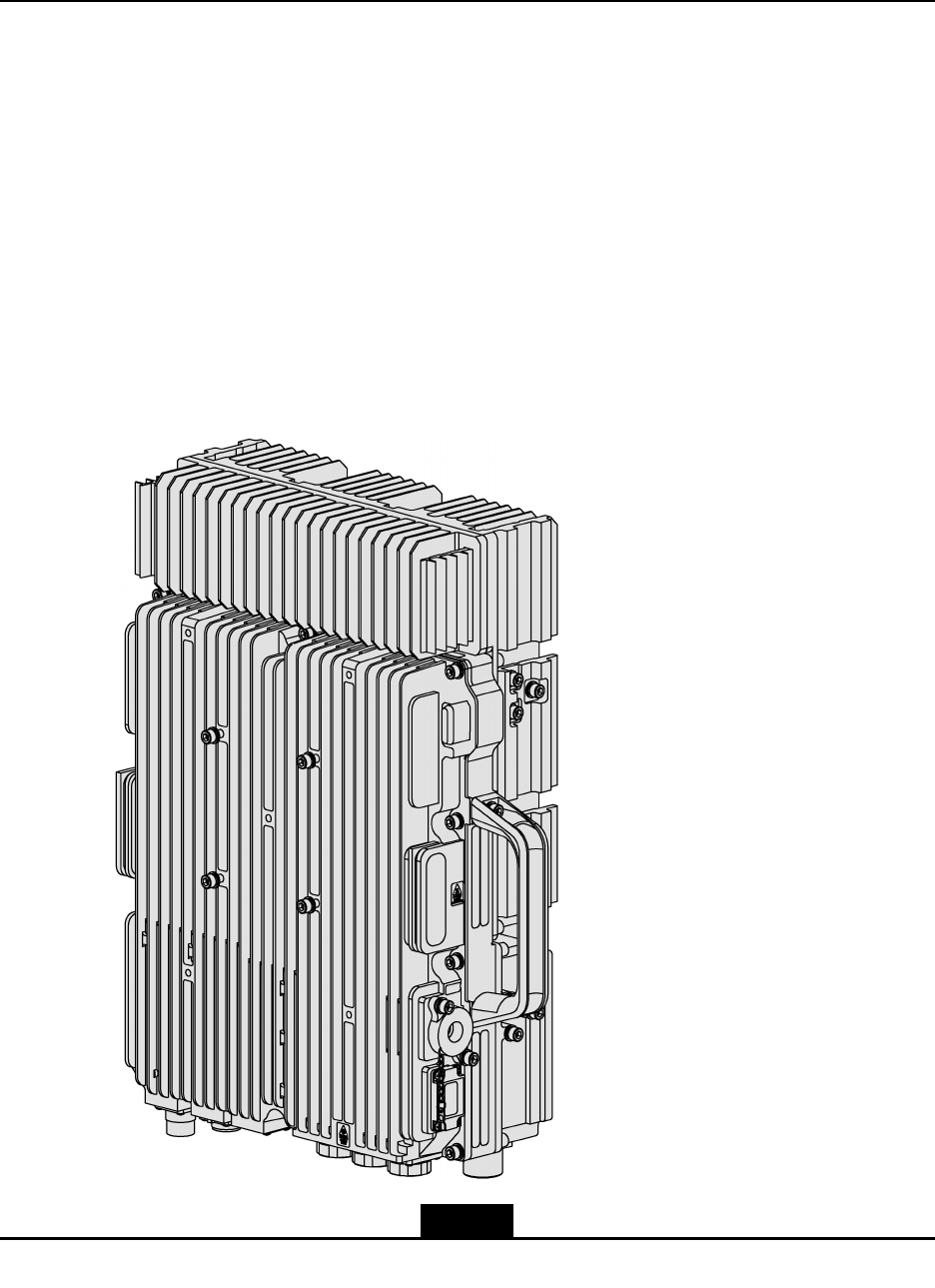
Figure1-1showstheZXSDRR8882deviceappearance.
Figure1-1ZXSDRR8882
1-1
SJ-20111021104623-004|2012–01-30(R1.1)ZTEProprietaryandCondential

ZXSDRR8882HardwareInstallationGuide
Dimensions:480mm(height)×320mm(width)×150mm(depth)
Weight:27kg
1.2PreparationforInstallation
1.2.1EnvironmentInspection
Beforeinstallingthedevice,installationpersonnelshouldmakesurethatthesite
environmentisinspectedandtheEnvironmentAcceptanceReportisissued.
1.2.2EquipmentTable
ThistablegivestheMaterielDescriptionandQuantityrequiredinstallingaZXSDRR8882.
Table1-1ZTEPartsandEquipmentListforaRRU
MaterialNameQuantity
R8882(RRU)1
RRUengineeringaccessory1
RRUinstallationassembly
(wall-mountedinstallationassembly,
pole-mountedinstallationassembly,or
L-shapedportalframe)
1
Devicehook(U-shapedhook)0–2(usedforMountingKit1)
RRUmountingpiece0–1(usedforMountingKit2)
RRUprotectionshade0–1(usedfortheRRUbase)
RRUexternalcable1
PIMDC0–1(usedwhentheR8882hasnobuilt-in
lightningarrester,currentlydoesnotsupporting
AC)
PIMDCmountingpiece0–1(optional,usedtosecurethePIMDCtothe
frontoranksidesoftheR8882)
1.2.3ToolsandMetersList
ThistableliststoolsandmetersrequiredinstallingZXSDRR8882.
1-2
SJ-20111021104623-004|2012–01-30(R1.1)ZTEProprietaryandCondential
Chapter1InstallationOverview
Table1-2ToolsandMetersList
ItemList
Measuringandruling
tools
5msteeltape,1mruler,gradienter,marker,drilling
template(deliveredwiththedevice)
DrillingtoolsElectricpercussiondrill(auxiliarydrillbits)andvacuum
cleaner
TighteningtoolsCrossscrewdrivers(M3–M6),Allenkey(M6),
adjustablewrench(M10),andtorquewrench
SmalltoolsSnipe-nosepliers,diagonalpliers,vices,le,hacksaw,
andhydraulicpressurepliers
General-purpose
tools
AuxiliarytoolsChainwheel,Ladder,Rope,scissors,slip-proof
gloves,safetyhelmet,connectorcard,paintbrush,and
hotairblower
Special-purposetoolsMulti-functionalcrimpingpliersandfeederconnector
knife
MetersDigitalmultimeter,VSWRtester,earthresistance
tester,basestationtester,compass,eldstrength
tester(forspecialpurpose),andspectrumanalyzer
(forspecialpurpose)
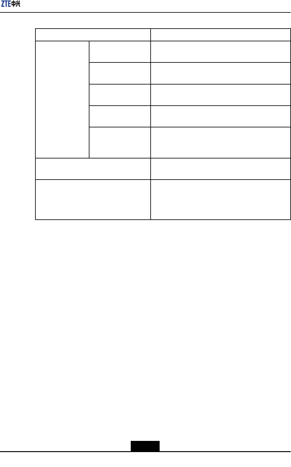
1.3InstallationSpaceRequirement
Figure1-2showstherecommendedspaceforinstallingZXSDRR8882.
1-3
SJ-20111021104623-004|2012–01-30(R1.1)ZTEProprietaryandCondential
ZXSDRR8882HardwareInstallationGuide
Figure1-2RecommendedSpaceforInstallingZXSDRR8882(Unit:mm)
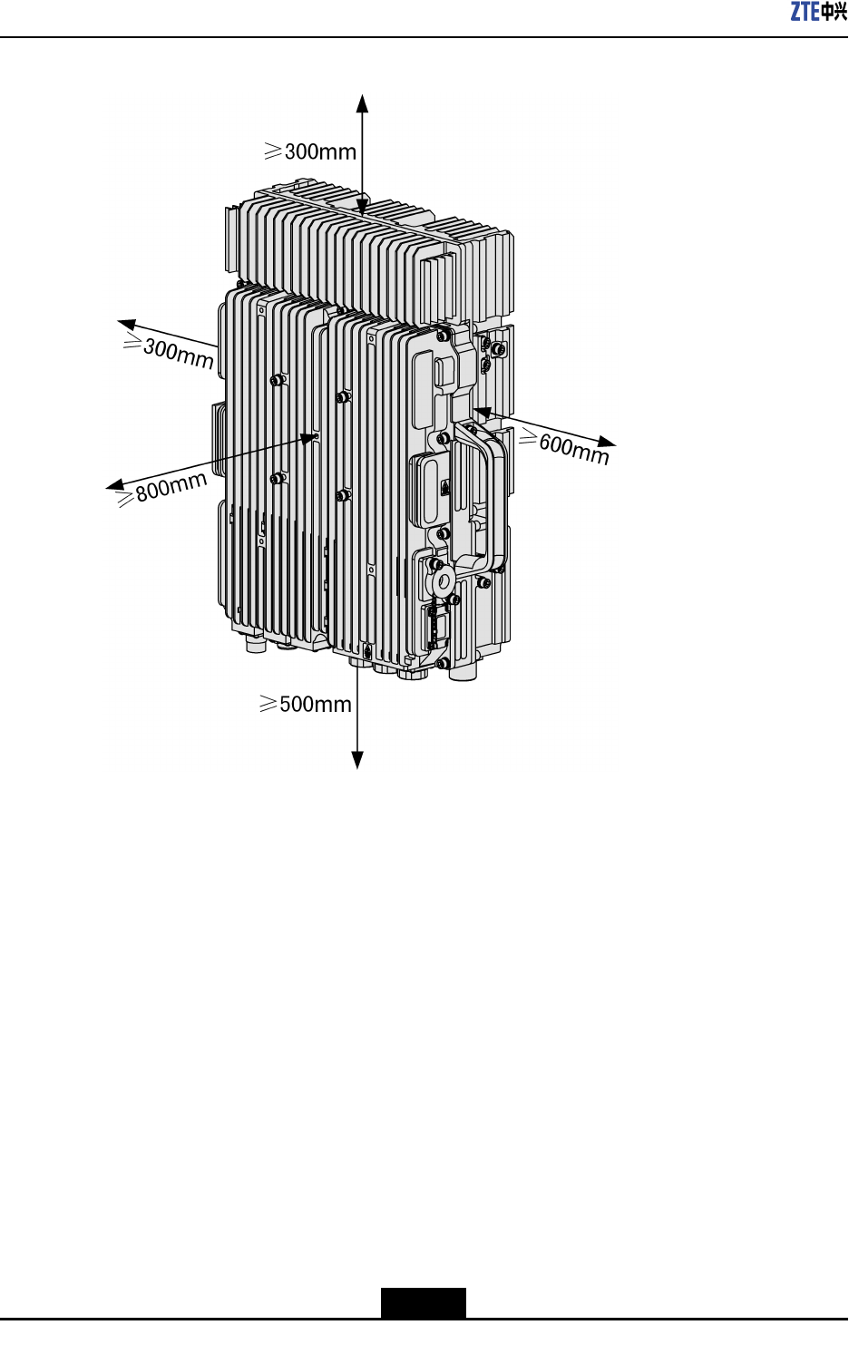
Figure1-3showstheminimumspaceforinstallingZXSDRR8882.
1-4
SJ-20111021104623-004|2012–01-30(R1.1)ZTEProprietaryandCondential
Chapter1InstallationOverview
Figure1-3MinimumSpaceforInstallingZXSDRR8882(Unit:mm)
1.4UnpackingInspection
1.4.1CountingGoods
Prerequisite
Thegoodshavebeendeliveredtothesiteforinstallation.
Context
Thegoodscountingneedstobejointlycompletedbytheengineer-ingtechniciansfrom
bothZTEandtheoperator.
Steps
1.Countthetotalnumberofcargos,thestatusofpackingcrateandtheshippingaddress
onthecargoneedtobechecked.Whenallinspectionsarepassed,starttheunpacking
inspection.
1-5
SJ-20111021104623-004|2012–01-30(R1.1)ZTEProprietaryandCondential

ZXSDRR8882HardwareInstallationGuide
2.Equipmentchecklistandunpackinginspectionreportarepackedincrate#1.The
unpackinginspectionreportneedtobecheckedoutandarchivedrst.
3.Ifanygoodsmissing,default,wrongequipments,inaccuracyinnumberordamages
arefound,theFeedbackForUnpackingInspectionneedstobelledoutby
engineeringsupervisorwithrelevantreason.ItshouldbesendbacktoZTEassoon
aspossibleforprocessing.
–EndofSteps–
1.4.2UnpackingCrate
Context
Therequiredtoolsareclawhammer,pliers,straightscrewdriverandcrowbar.
Steps
1.Insertastraightscrewdriveroraclawhammerintothemetallockonthecoverofthe
woodencrate.Rotatethescrewdriverortheclawhammertoloosentheironsheet.
Thenopenitwithcrowbarandpliers.
2.Openupalltheothermetallocksonthewoodencratetopsurfaceandremovethetop
cover.
3.Takeoutthecartonfromthewoodencrate.
–EndofSteps–
1.4.3UnpackingCarton
Context
Cartonsaregenerallyusedforpackingsparepartsforelectronicequipments,terminal
devicesandancillarymaterials.Sparepartsforelectronicequipmentsaredeliveredin
static-freebags.Thestatic-freeprotectivemeasuresareneededwhenunpacking.
Unpackingtools:Obliqueclamp,papercutter
Followthetwopointsduringtheunpackingprocess:
lThestatic-freebagshouldnotbebrokenforfuturestorageorrepairpurpose.
lDesiccantinthecartonshouldbeproperlydisposedandbekeptawayfromchildren.
Steps
1.Cutoffpackingbandswiththeobliqueclamp.
2.Slicealongthetapesontheedgesofthecasecoverandmindthedepthwhencutting.
3.Openupthecartonandtakeoutthebubbles.
4.Checkoutthegoodsaccordingtothechecklistattachedtothecarton.
1-6
SJ-20111021104623-004|2012–01-30(R1.1)ZTEProprietaryandCondential

Chapter1InstallationOverview
5.Takeoutthestatic-freebag.
6.Openupthestatic-freebagandtakeouttheelectronicdevice.
–EndofSteps–
1.4.4AcceptanceandHandover
Steps
1.Inspection
Checkthegood'sname,model,numberetcagainstthepackinglist.Verifyeachgoods
accordingtothefollowingitems:
lAnyconcave,convex,scratches,peeling,blistering,blotoutsidethecase.
lAnypaintstripping,scratchesonthecase.
lAnyloosingscrew,dropboltsordislocation.
lAnymissingparts.
Placethegoodsinspectedbycategories.
2.Delivery
Thecustomerrepresentativeandengineeringsupervisorneedtosignonthe
Unpackinginspectionreportaftertheinspection.Ifthecontractspeciesthegoodsbe
keptbythecustomeraftertheinspection,bothpartiesneedtosignontheUnpacking
InspectionReportandtransferthegoodstothecustomer.
–EndofSteps–
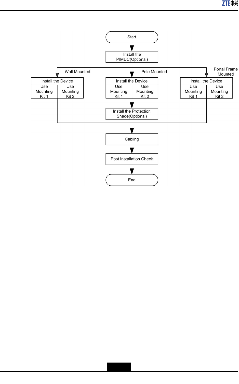
1.5InstallationFlow
Figure1-4showstheowchartofinstallingZXSDRR8882,includingPIMDCinstallation,
deviceinstallation,andcabling.
1-7
SJ-20111021104623-004|2012–01-30(R1.1)ZTEProprietaryandCondential
ZXSDRR8882HardwareInstallationGuide
Figure1-4FlowchartofInstallingZXSDRR8882
1-8
SJ-20111021104623-004|2012–01-30(R1.1)ZTEProprietaryandCondential
Chapter2
PIMDCInstallation
TableofContents
Overview....................................................................................................................2-1
InstallingthePIMDContheFrontoftheDevice.........................................................2-2
InstallingthePIMDContheSideoftheDevice...........................................................2-2
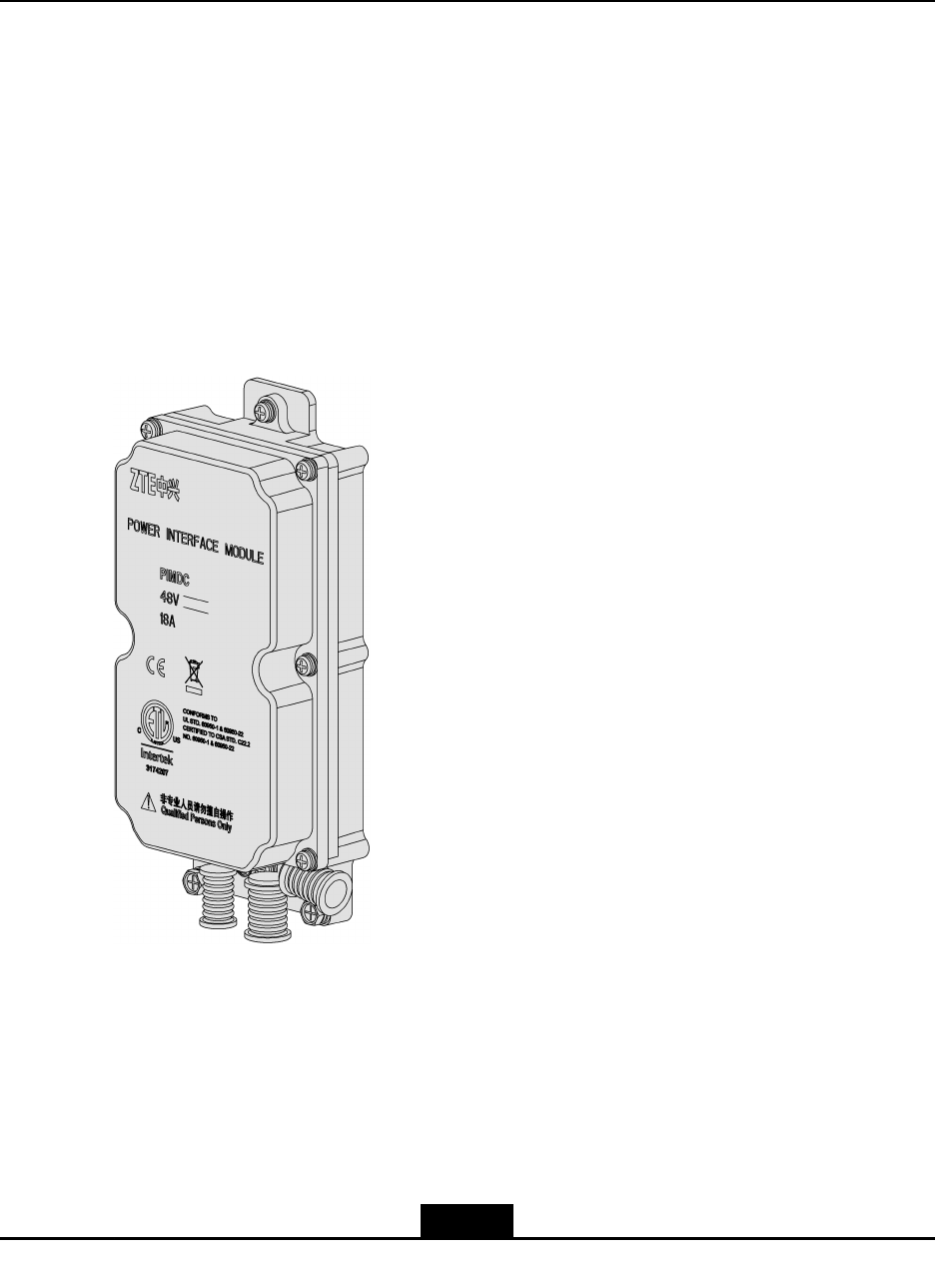
2.1Overview
Figure2-1showstheappearanceofthepowerinterfacemoduleDC(PIMDC).
Figure2-1PIMDCAppearance
ThedimensionsofaPIMDCare233.2mm(Height)×119mm(Width)×55mm(Depth).
IfthedeviceisconguredwithaPIMDC,installationpersonnelcaninstallthePIMDConto
thedevicebeforeinstallingthedevice.ThePIMDCcanbeinstalledonthefrontorsideof
thedevice.
2-1
SJ-20111021104623-004|2012–01-30(R1.1)ZTEProprietaryandCondential
ZXSDRR8882HardwareInstallationGuide
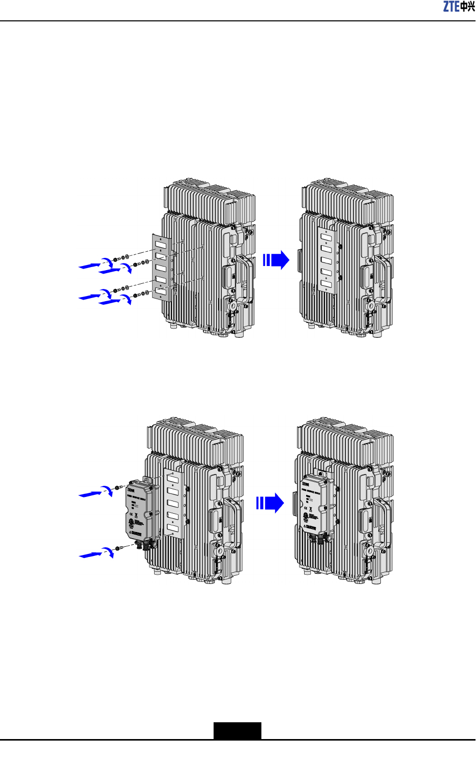
2.2InstallingthePIMDContheFrontoftheDevice
Steps
1.PutthePIMDCmountingpieceinplaceandaligntheholesonthePIMDCmounting
piecewiththemountingholesonthedevice.
2.TightenthefourM6screwswithascrewdriver,asshowninFigure2-2.
Figure2-2SecuringthePIMDCMountingBaseontheFrontoftheDevice
3.PlacethePIMDConthemountingpieceandtightenthetwocaptivescrewswitha
screwdriver,asshowninFigure2-3.
Figure2-3SecuringthePIMDContheFrontoftheDevice
–EndofSteps–
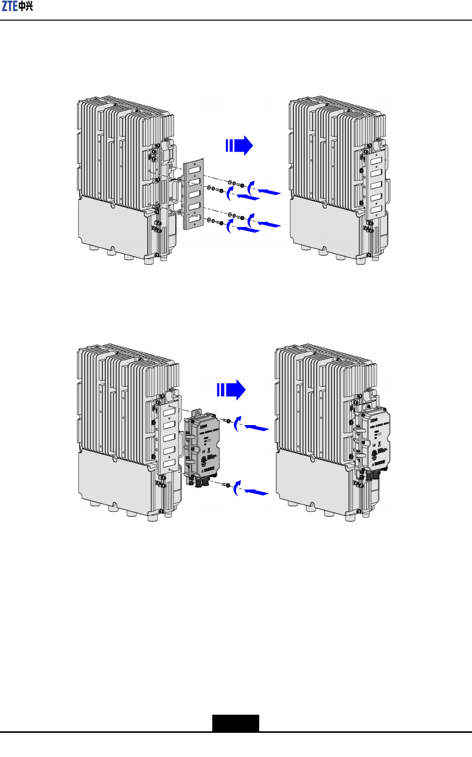
2.3InstallingthePIMDContheSideoftheDevice
Steps
1.UnscrewthefourscrewsontheleftsideoftheRRUwithanAllenkey.
2-2
SJ-20111021104623-004|2012–01-30(R1.1)ZTEProprietaryandCondential
Chapter2PIMDCInstallation
2.PutthePIMDCmountingpieceinplaceandtightenthefourM6screwswithanAllen
key,asshowninFigure2-4.
Figure2-4SecuringthePIMDCMountingBaseontheSideoftheDevice
3.PlacethePIMDConthemountingpieceandtightenthetwocaptivescrewswitha
screwdriver,asshowninFigure2-5.
Figure2-5SecuringthePIMDContheSideoftheDevice
–EndofSteps–
2-3
SJ-20111021104623-004|2012–01-30(R1.1)ZTEProprietaryandCondential

ZXSDRR8882HardwareInstallationGuide
Thispageintentionallyleftblank.
2-4
SJ-20111021104623-004|2012–01-30(R1.1)ZTEProprietaryandCondential

Chapter3
DeviceInstallation
TableofContents
Overview....................................................................................................................3-1
InstallationAssemblies...............................................................................................3-2
Wall-MountedInstallation...........................................................................................3-7
Pole-MountedInstallation.........................................................................................3-14
PortalFrame-MountedInstallation............................................................................3-23
InstallingtheProtectionShade.................................................................................3-26
3.1Overview
Dependingontheconguredinstallationassemblies,installationpersonnelcaninstall
ZXSDRR8882inoneofthefollowingmodes:
lWall-mountedinstallation
lPole-mountedinstallation
lPortalframe-mountedinstallation
Thefollowingtabledescribestheinstallationpositionssupportedbytheinstallation
assembliesofZXSDRR8882.
Table3-1InstallationPositionsSupportedbytheInstallationAssembliesofZXSDR
R8882
InstallationPositionDescription
Roundpoleφ60mm–φ120mm(GB/T8162-99,φ60,φ76,φ89,andφ114):
supportssingle-unit,double-unit,triple-unit,andquadro-unit
solutions.
φ40mm–φ60mm:
supportsonlysingle-unitanddouble-unitsolutions.
Channelsteel60mm–100mm(GB/T707—19886.3,6.5,8,and10):supports
thesingle-unitsolution.
Anglesteel63mm–100mm(anglesteelNo.6.3,7,7.5,8,9,and10):supports
thesingle-unitsolution.
High-speedrailwaytunnelSupportsthesingle-unitsolution.Installationpersonnelcanuse
someassemblypartsofthewall-mountedmodeanddesignsome
newassemblypartsasrequired.Thedesignedassemblyparts
shouldsupporttheRRUinstallationinterfaces.
3-1
SJ-20111021104623-004|2012–01-30(R1.1)ZTEProprietaryandCondential
ZXSDRR8882HardwareInstallationGuide
InstallationPositionDescription
Indoor/OutdoorwallSupportsthesingle-unitsolution.Theassemblypartsarethesame
asthatinpole-mountedmode.
IndoorportalframeSupportsfourRRUs.Theassemblypartsarethesameasthat
inpole-mountedmode.
3.2InstallationAssemblies
Basedontheinstallationmodeandinstallationassembly,installationpersonnelcaninstall
ZXSDRR8882inoneofthefollowingsixways:
lUsemountingkit1tomountthedeviceonawall.
lUsemountingkit2tomountthedeviceonawall.
lUsemountingkit1tomountthedeviceonapole.
lUsemountingkit2tomountthedeviceonapole.
lUsemountingkit1tomountthedeviceonaportalframe.
lUsemountingkit2tomountthedeviceonaportalframe.
InstallationAssemblyofMountingKit1(Wall-Mounted)
Table3-2describestheinstallationassemblyofmountingkit1forwall-mountedinstallation.
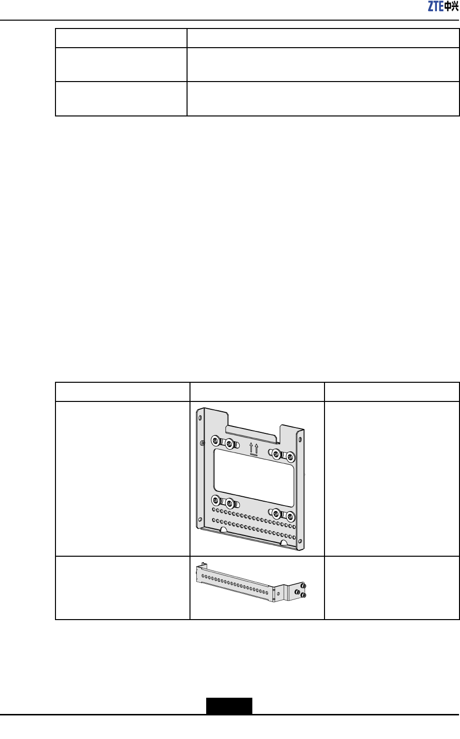
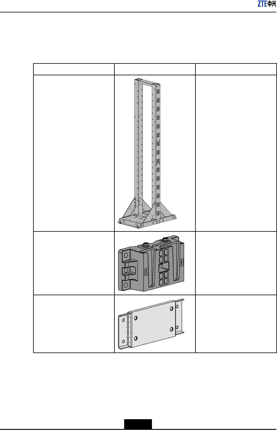
Table3-2InstallationAssemblyofMountingKit1(Wall-Mounted)
NameAppearanceFunction
WallmountingassemblyItisusedtomountZXSDR
R8882onawall.
Devicehook(U-shapedhook)InstalltwoU-shapedhooks
atthebackofthedeviceto
connectandsecureZXSDR
R8882
InstallationAssembliesofMountingKit2(Wall-Mounted)
Table3-3describestheinstallationassembliesofmountingkit2forwall-mounted
installation.
3-2
SJ-20111021104623-004|2012–01-30(R1.1)ZTEProprietaryandCondential
Chapter3DeviceInstallation
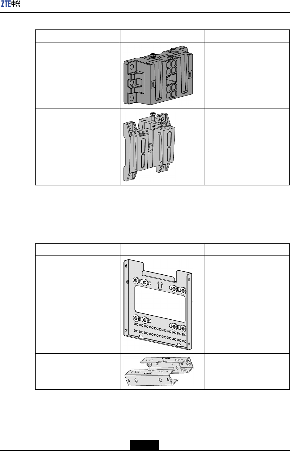
Table3-3InstallationAssembliesofMountingKit2(Wall-Mounted)
NameAppearanceFunction
WallmountingassemblyItisusedtomountZXSDR
R8882onawall.
RRUmountingbaseItisinstalledontheback
orsideofZXSDRR8882to
secureZXSDRR8882on
thewallmountingassembly,
polemountingassembly,
parallelmountingbase,orpole
mountingclamp.
InstallationAssembliesofMountingKit1(Pole-Mounted)
Table3-4describestheinstallationassembliesofmountingkit1forpole-mounted
installation.
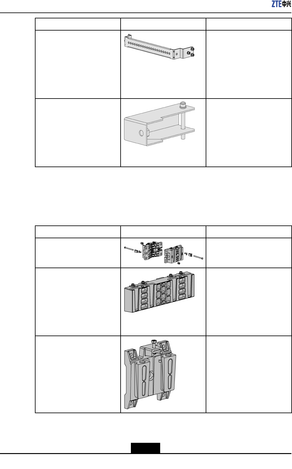
Table3-4InstallationAssembliesofMountingKit1(Pole-Mounted)
NameAppearanceFunction
WallmountingassemblyItisusedtomountZXSDR
R8882.
PolemountingpieceItisusedtosecureZXSDR
R8882onapole.
3-3
SJ-20111021104623-004|2012–01-30(R1.1)ZTEProprietaryandCondential
ZXSDRR8882HardwareInstallationGuide
NameAppearanceFunction
Devicehook(U-shapedhook)InstalltwoU-shapedhooks
atthebackofthedeviceto
connectandsecureZXSDR
R8882
ExtensionpieceItisusedtoextendthepole
mountingpiecetomount
ZXSDRR8882withthewall
mountingassembly.
InstallationAssembliesofMountingKit2(Pole-Mounted)
Table3-5describestheinstallationassembliesofmountingkit2forpole-mounted
installation.
Table3-5InstallationAssembliesofMountingKit2(Pole-Mounted)
NameAppearanceFunction
PolemountingassemblyItisusedtosecureZXSDR
R8882onapole.
ParallelmountingbaseItisusedtomountthreeZXSDR
R8882sonapole.Oneparallel
mountingbasecanmounttwo
ZXSDRR8882s.Theparallel
mountingbaseislocated
betweentheRRUmounting
baseandpolemountingpiece.
RRUmountingbaseItisinstalledontheback
orsideofZXSDRR8882to
secureZXSDRR8882on
thewallmountingassembly,
polemountingassembly,
parallelmountingbase,orpole
mountingclamp.
3-4
SJ-20111021104623-004|2012–01-30(R1.1)ZTEProprietaryandCondential
Chapter3DeviceInstallation
InstallationAssembliesofMountingKit1(PortalFrame-Mounted)
Table3-6describestheinstallationassembliesofthemountingkit1forportal
frame-mountedinstallation.
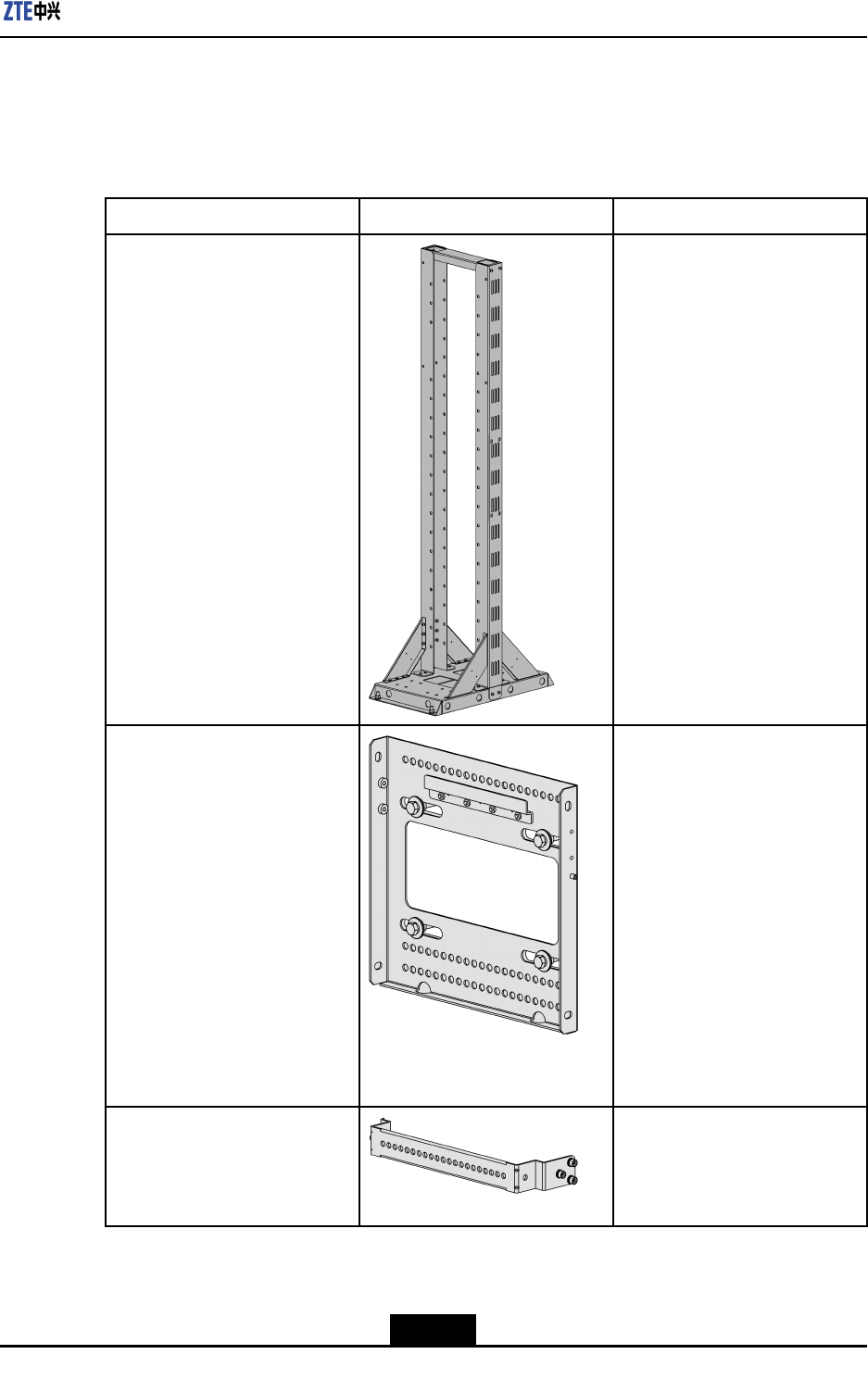
Table3-6InstallationAssembliesoftheMountingKit1(PortalFrame-Mounted)
NameAppearanceFunction
PortalframeItisxedontheindooroorto
mountthemountingpanel.
MountingpanelItisinstalledontheportalframe
tosecureZXSDRR8882.
Devicehook(U-shapedhook)InstalltwoU-shapedhooks
atthebackofthedeviceto
connectandsecureZXSDR
R8882
3-5
SJ-20111021104623-004|2012–01-30(R1.1)ZTEProprietaryandCondential
ZXSDRR8882HardwareInstallationGuide
InstallationAssembliesofMountingKit2(PortalFrame-Mounted)
Table3-7describestheinstallationassembliesofmountingkit2forportalframe-mounted
installation.
Table3-7InstallationAssembliesofMountingKit2(PortalFrame-Mounted)
NameAppearanceFunction
PortalframeItisxedontheindooroorto
mountthepolemountingclamp.
PolemountingclampItisinstalledontheportalframe
tosecureZXSDRR8882.
TransitionboardItisusedtosecurethepole
clipstotheportalframe.
3-6
SJ-20111021104623-004|2012–01-30(R1.1)ZTEProprietaryandCondential
Chapter3DeviceInstallation
NameAppearanceFunction
RRUmountingbaseItisinstalledontheback
orsideofZXSDRR8882to
secureZXSDRR8882on
thewallmountingassembly,
polemountingassembly,
parallelmountingbase,orpole
mountingclamp.
3.3Wall-MountedInstallation
3.3.1UsingMountingKit1toMounttheDeviceonaWall
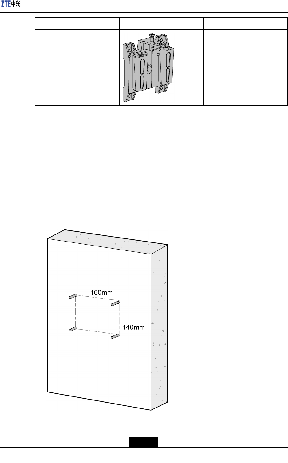
Steps
1.Identifytheinstallationpositiononthewallanddrawlines:Drawlinesonthewallby
usingthedrillingtemplateandmarkthefourdrillingpositions,asshowninFigure3-1.
Figure3-1DrillingPositions
3-7
SJ-20111021104623-004|2012–01-30(R1.1)ZTEProprietaryandCondential
ZXSDRR8882HardwareInstallationGuide
2.Drillholesandinstallexpansionbolts:DrillfourФ16mm×80mmholesatthemarked
drillingpositionsbyusingapercussiondrillandinstallexpansionbolts.Useavacuum
cleanertocleanthedustwhendrillingholes.
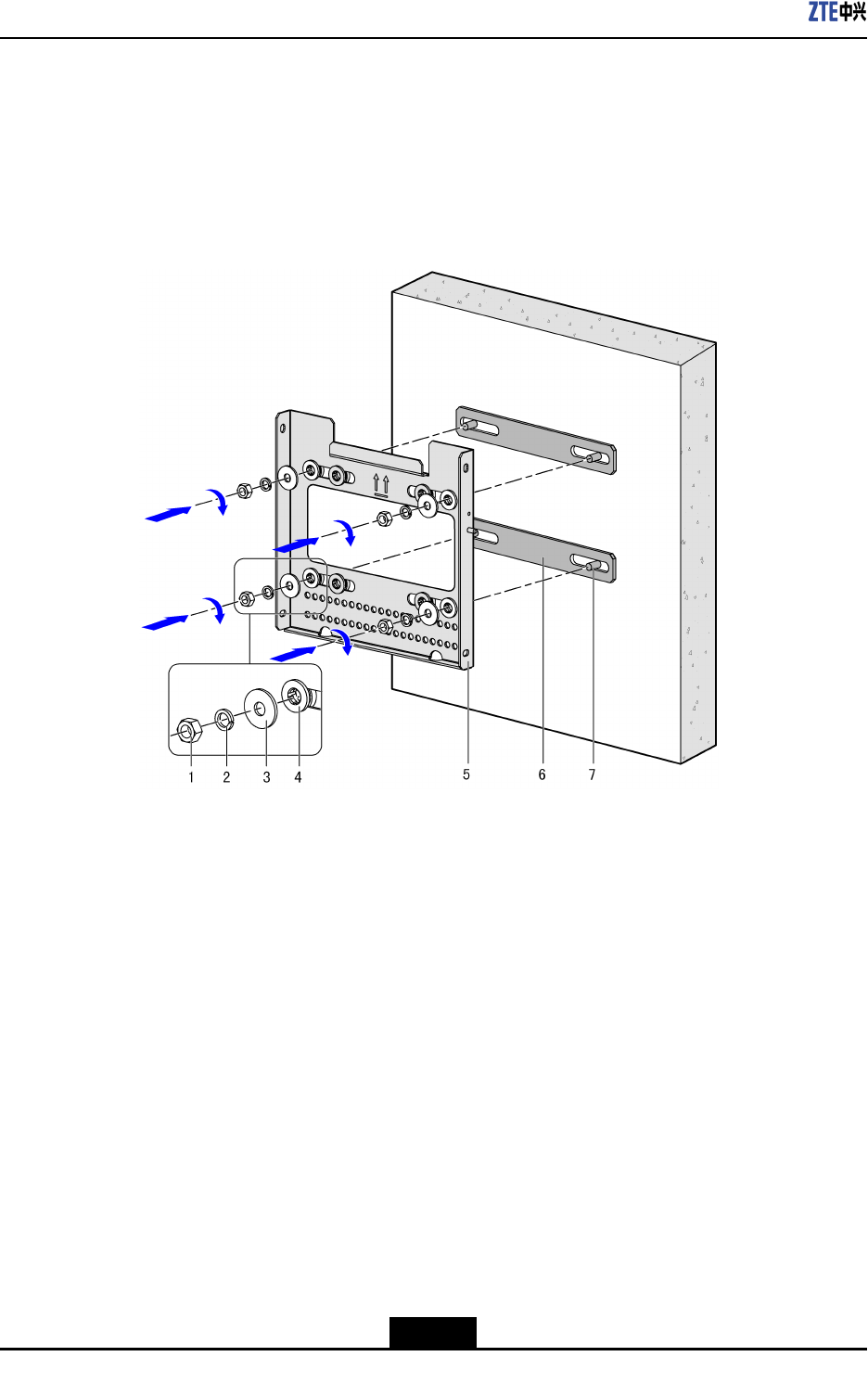
3.Securethewallmountingassembly:Securethewallmountingassemblyonthewall
withthenutsremovedfromtheexpansionbolts,asshowninFigure3-2.
Figure3-2SecuringtheWallMountingAssembly
1.Nut
2.Springwasher
3.Flatwasher
4.Insulationwasher
5.Wallmounting
assembly
6.Insulationplate
7.Expansionbolts
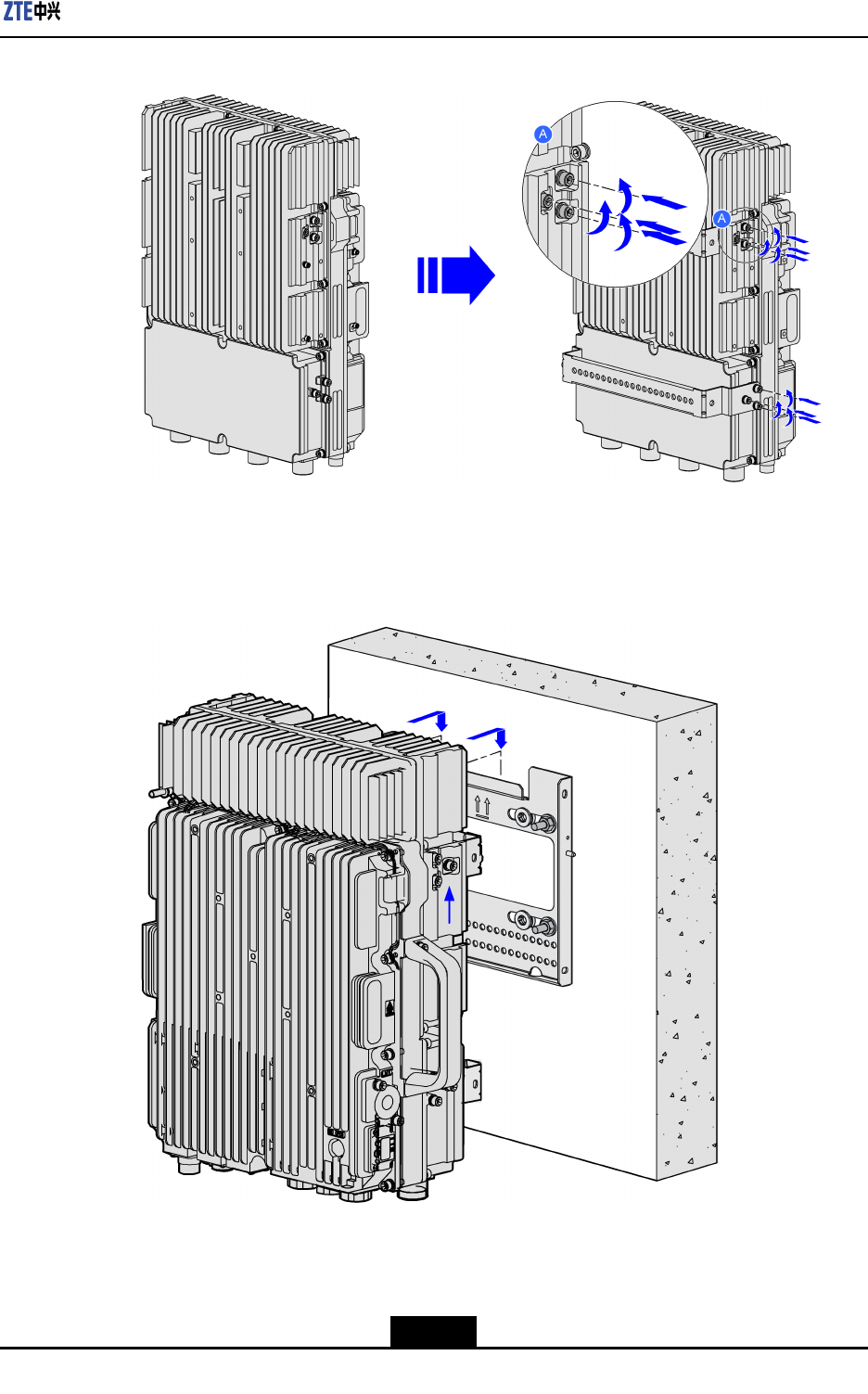
4.Installdevicehooks(twoU-shapedhooks):Usethe12M16boltsdisassembledfrom
theZXSDRR8882tosecurethetwoU-shapedhookstothebackofthedevice.See
Figure3-3.
3-8
SJ-20111021104623-004|2012–01-30(R1.1)ZTEProprietaryandCondential
Chapter3DeviceInstallation
Figure3-3InstallDeviceHooks(TwoU-shapedHooks)
5.Mountthedeviceonthewallmountingassembly:HangZXSDRR8882onthehook
onthewallmountingassembly,asshowninFigure3-4.
Figure3-4MountingtheDeviceontheWallMountingAssembly
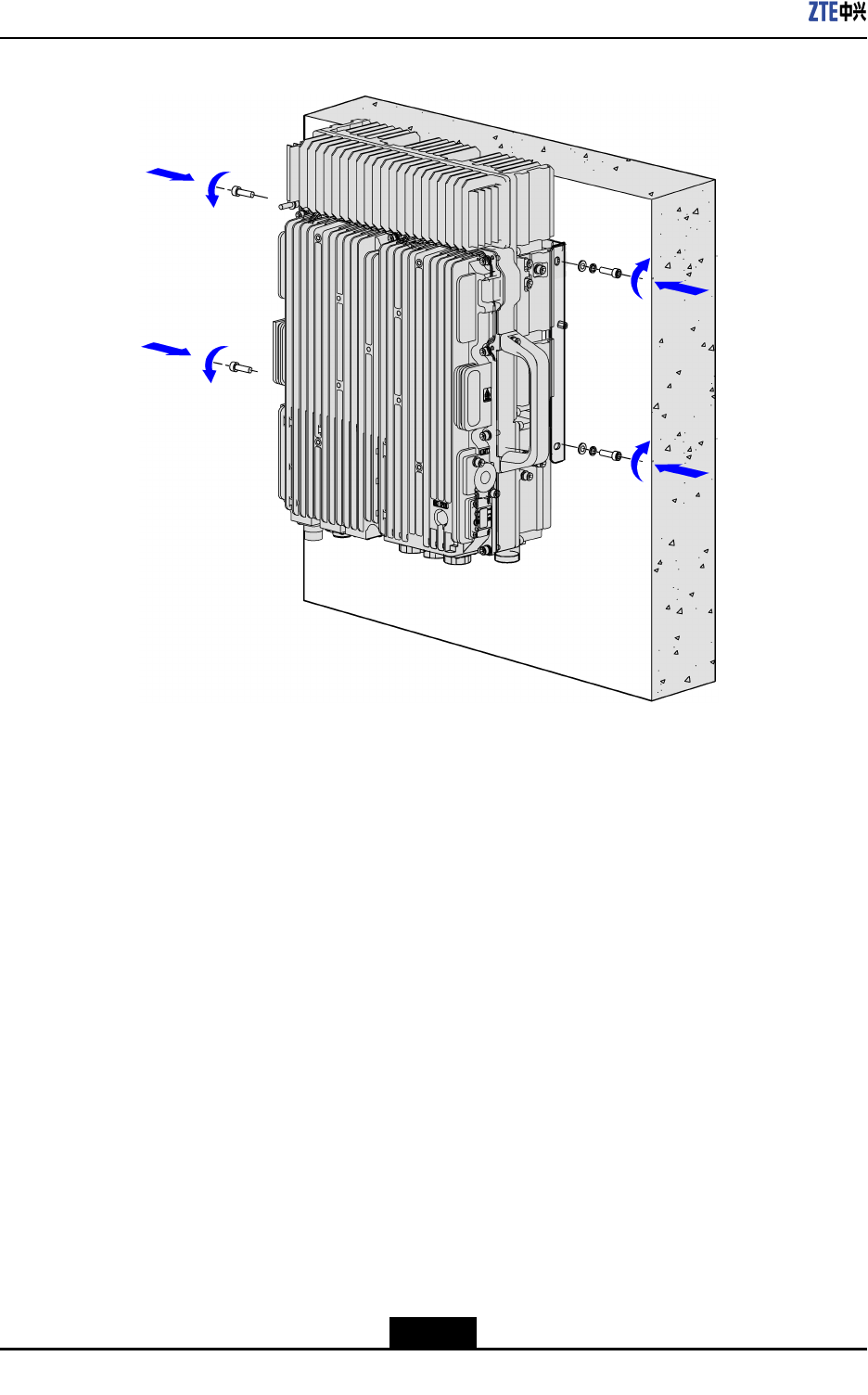
6.Securethedevice:SecureZXSDRR8882onthewallmountingassemblywithfour
M6screws,asshowninFigure3-5.
3-9
SJ-20111021104623-004|2012–01-30(R1.1)ZTEProprietaryandCondential
ZXSDRR8882HardwareInstallationGuide
Figure3-5SecuringtheDevice
–EndofSteps–
3.3.2UsingMountingKit2toMounttheDeviceonaWall
Steps
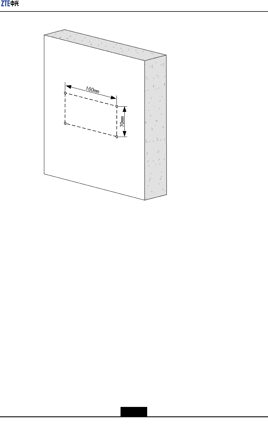
1.Identifytheinstallationpositiononthewallanddrawlines:Drawlinesonthewallby
usingthedrillingtemplateandmarkthefourdrillingpositions,asshowninFigure3-6.
3-10
SJ-20111021104623-004|2012–01-30(R1.1)ZTEProprietaryandCondential
Chapter3DeviceInstallation
Figure3-6DrillingPositions
2.Drillholesandinstallexpansionbolts:DrillfourФ16mm×80mmholesatthemarked
drillingpositionsbyusingapercussiondrillandinstallexpansionbolts.Useavacuum
cleanertocleanthedustwhendrillingholes.
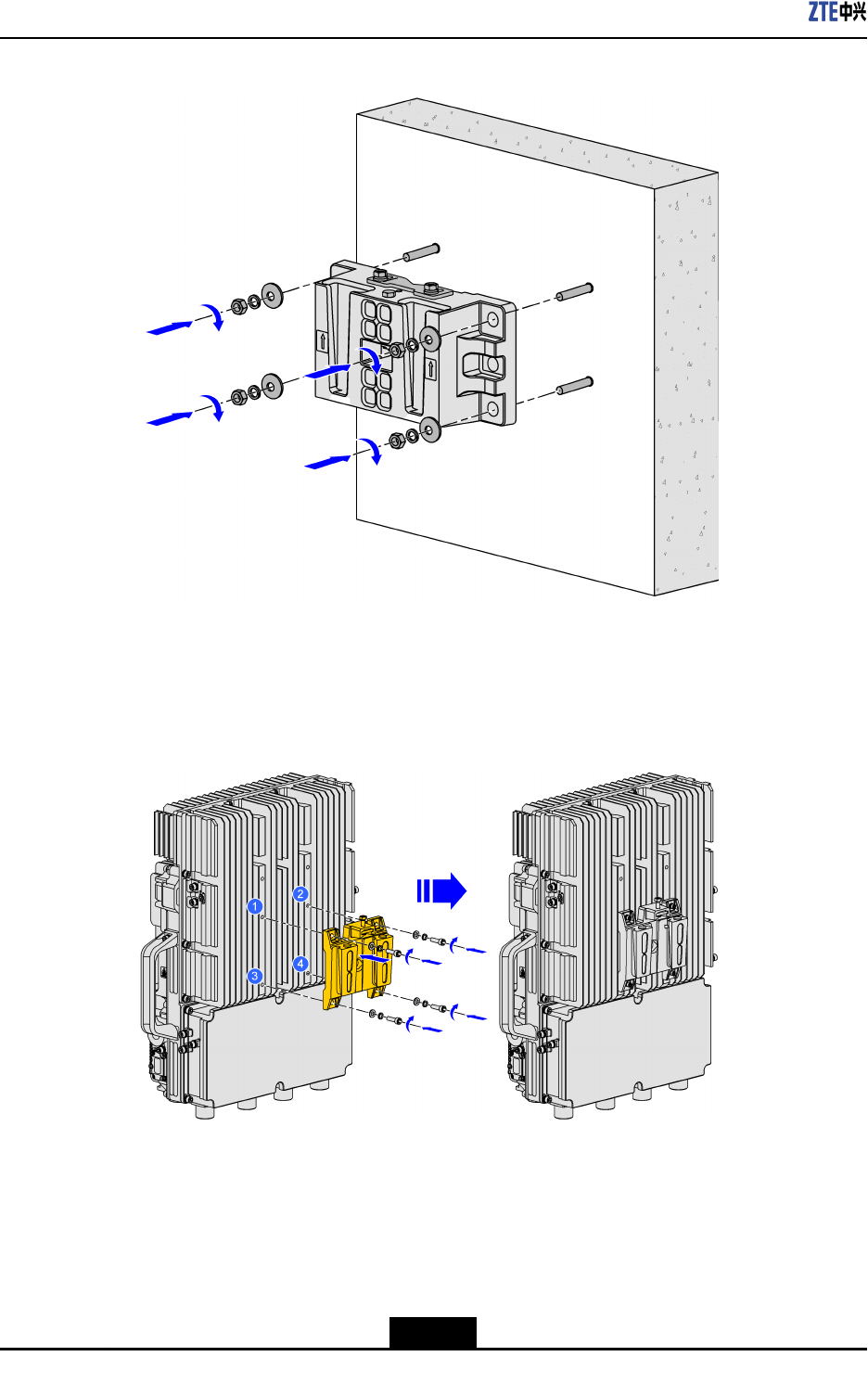
3.Securethewallmountingassembly:Securethewallmountingassemblyonthewall
withthenutsremovedfromtheexpansionbolts,asshowninFigure3-7.
3-11
SJ-20111021104623-004|2012–01-30(R1.1)ZTEProprietaryandCondential
ZXSDRR8882HardwareInstallationGuide
Figure3-7SecuringtheWallMountingAssembly
4.InstalltheRRUmountingbaseonthebackofthedevice:Aligntheholesontheback
ofthedevicewiththeholesontheRRUmountingbaseandsecuretheRRUmounting
baseonthebackofthedevicewithfourM6screws,asshowninFigure3-8.
Figure3-8InstallingtheRRUMountingBaseontheBackoftheDevice
5.Mountandsecurethedevice:MounttheRRUmountingbaseonthewallmounting
assembly,pushthelockingshimtolocktheRRUmountingbase,andthentightenthe
twoscrewsonthelockingshim,asshowninFigure3-9andFigure3-10.
3-12
SJ-20111021104623-004|2012–01-30(R1.1)ZTEProprietaryandCondential