Zebra Technologies MC55N0 ENTERPRISE DIGITAL ASSISTANT (EDA) User Manual REVISED 3
Zebra Technologies Corporation ENTERPRISE DIGITAL ASSISTANT (EDA) REVISED 3
Contents
REVISED USER MANUAL 3
Operation 2 - 17
•
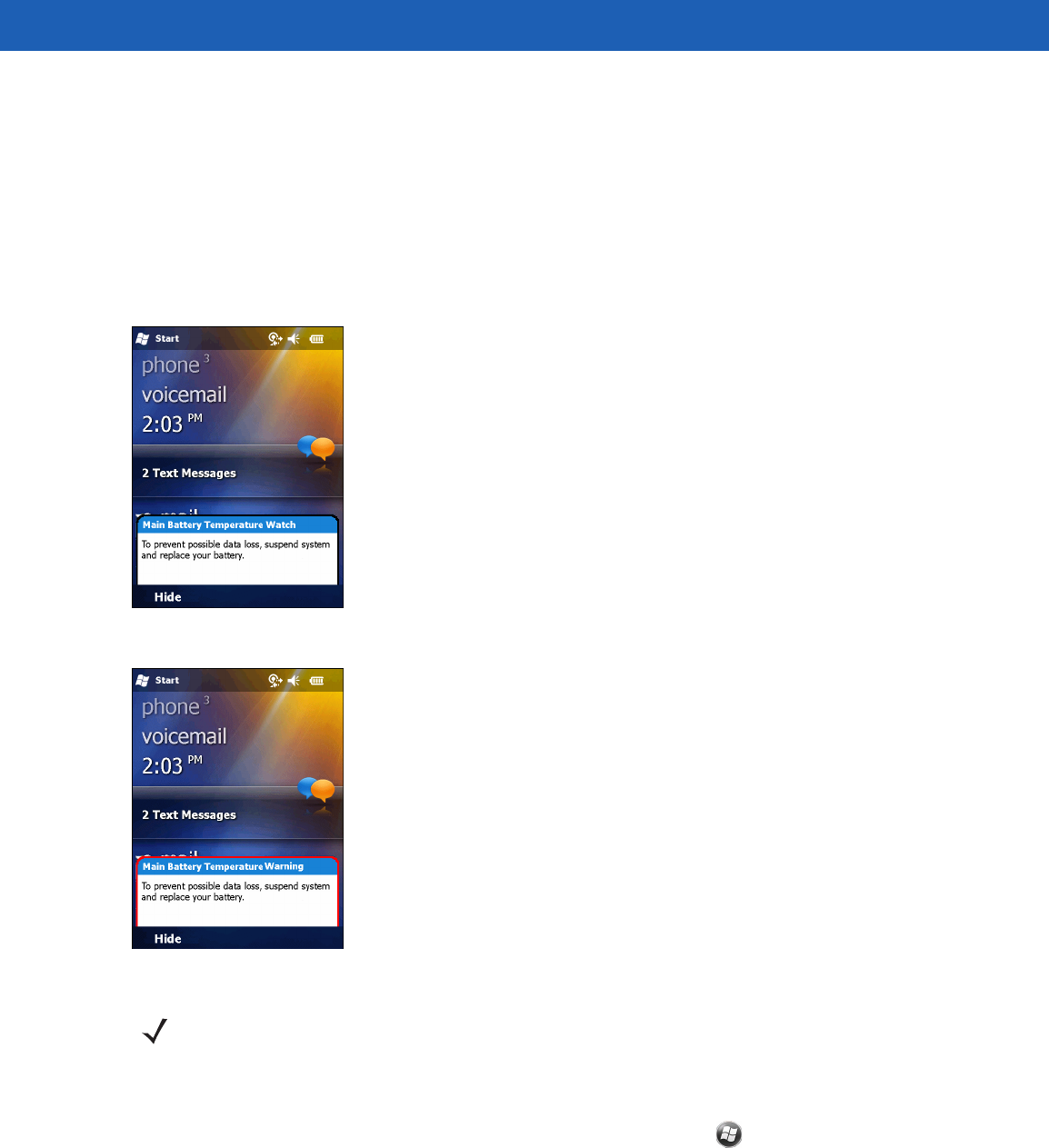
Level 1: Temperature Watch; this level is similar to main battery low warning. It indicates that the
battery temperature has reached the first threshold level. The user should move to an environment within
proper operating temperature.
•
Level 2: Temperature Warning; this level is similar to main battery very low warning. It indicates the
battery temperature has reached the second threshold level. The user should close all running
applications and stop using the MC55.
•
Level 3: Temperature Error; this level indicates the battery has reached an unusable temperature
threshold and immediately suspends the MC55. This level does not have any graphical notification
associated with it.
Figure 2-20
Main Battery Temperature Watch Dialog Box
Figure 2-21
Main Battery Temperature Warning Dialog Box
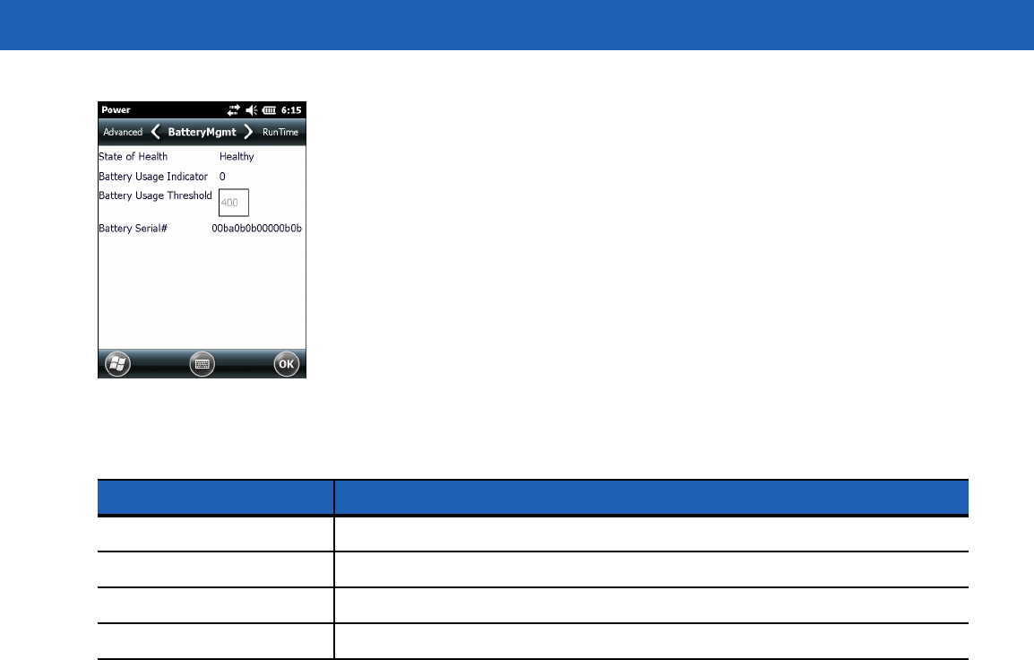
Battery Health
The health of the battery can be viewed on the MC55 Power applet. Tap > Settings > System > Power >
BatteryMgmt.
NOTE The Temperature Warning dialog box remains visible until you tap Hide.
2 - 18 MC55A0/MC55N0 Enterprise Digital Assistant User Guide
Figure 2-22
Battery Management Dialog Box
For information on changing the Battery Usage Threshold, refer to the MC55 Integrator Guide.
Table 2-6
Battery Information
Item Description
State of Health Indicates the current state of the battery (Healthy or Unhealthy).
Battery Usage Indicator Indicates the usage of the battery.
Battery Usage Threshold Indicates the usage indicator threshold.
Battery Serial # Displays the serial number of the battery.
Operation 2 - 19
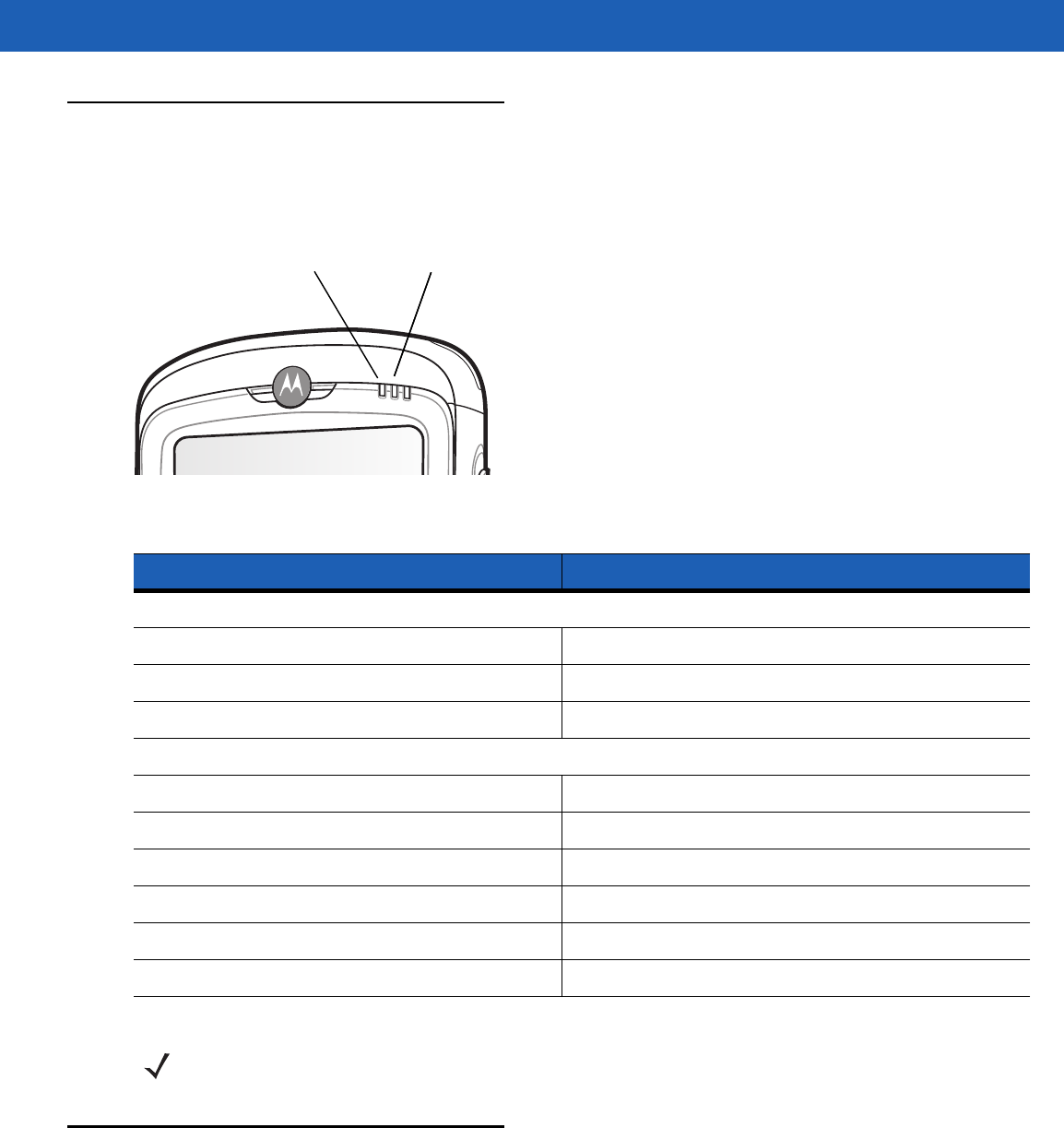
LED Indicators
The MC55 has three LED indicators. The Scan/Decode LED indicates status for scanning. The
Charging/Battery Status LED indicates battery charging and status.
Figure 2-23
LED Indicators
Resetting the MC55
There are two reset functions, warm boot and cold boot. A warm boot restarts the MC55 by closing all running
programs. A cold boot also restarts the MC55, and also initializes some drivers. Data saved in flash memory or
a memory card is not lost.
If the MC55 is not functioning properly, perform a warm boot first. If the MC55 still does not respond, perform a
cold boot.
Table 2-7
LED Indications
LED State Indication
Scan/Decode LED
Solid Green Successful decode/capture.
Solid Red Laser enabled, scanning/imaging in process.
Off Not enabled.
Charging/Battery Status LED
Slow Blinking Amber Main battery in MC55 is charging.
Solid Amber Main battery in MC55 is fully charged.
Fast Blinking Amber Charging error.
Off Not charging.
Single Blink Amber (when Power button pressed) Battery depleted.
Blinking Amber (when Power button pressed) Battery over-temperature condition.
Scan/Decode
LED
Charging/Battery
Status LED
Charging/Battery
Status LED
NOTE For information about scanning/decoding, see Chapter 3, Data Capture.

2 - 20 MC55A0/MC55N0 Enterprise Digital Assistant User Guide
Performing a Warm Boot
Hold down the red Power button for approximately five seconds. As soon as the MC55 starts to boot (splash
screen displays) release the Power button.
Performing a Cold Boot
To perform a cold boot:
•
On a numeric keypad, simultaneously press the red Power button and the and keys.
•
On an alphanumeric keypad, simultaneously press the red Power button and the and keys.
•
On an PIM keypad, simultaneously press the red Power button and the and keys.
Waking the MC55
The wake-up conditions define what actions wake up the mobile computer after it has gone into suspend
mode. The mobile computer can go into suspend mode by either pressing the Power button or automatically by
Control Panel time-out settings. These settings are configurable and the factory default settings are shown in
Table 2-8 are subject to change/update.
Table 2-8
Wake-up Default Settings
Condition for Wake-up Power Button Automatic Time-out
AC power is applied. No Yes
Mobile computer is inserted into a cradle. No Yes
Mobile computer is removed from a cradle. No Yes
Mobile computer is connected to a USB device. Yes Yes
A key is pressed. No Yes
The scan triggered is pressed. No Yes
The screen is touched. No No
Bluetooth communication Yes Yes
IST activity No Yes
USB Host connected No No
Operation 2 - 21
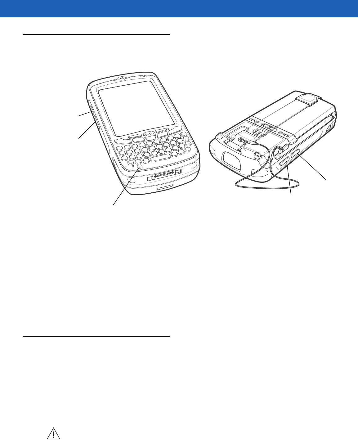
Function Buttons
The MC55’s buttons perform certain functions.
Figure 2-24
Function Buttons
•
Power: Press the red Power button to turn the MC55 screen on and off. The MC55 is in suspend mode
when the screen is off. For more information, see Powering On the MC55 on page 1-7. Also use the
Power button to reset the MC55 by performing a warm or cold boot. See Resetting the MC55 on page
2-19.
•
Scan/Action: Press to scan bar codes or capture images. See Chapter 3, Data Capture.
Or, press to open an application or perform a function. See the Microsoft® Applications for Mobile 6 User
Guide to set an application to open.
•
Volume Up/Down: Press to increase or decrease the MC55’s volume.
•
Action: Press to open an application or perform a function. See the Microsoft® Applications for Windows
Mobile 6 User Guide to set an application to open.
Stylus
Use the MC55 stylus to select items and enter information. The stylus functions as a mouse.
•
Tap: Touch the screen once with the stylus to press option buttons and open menu items.
•
Tap and Hold: Tap and hold the stylus on an item to see a list of actions available for that item. On the
pop-up menu that appears, tap the action to perform.
•
Drag: Hold the stylus on the screen and drag across the screen to select text and images. Drag in a list to
select multiple items.
Scan/Action
Button
Power Button
Volume
Up/Down
Button
Action Button
Scan/Action
Button
CAUTION To prevent damage to the screen, do not use any device other than the Motorola-provided stylus.
2 - 22 MC55A0/MC55N0 Enterprise Digital Assistant User Guide
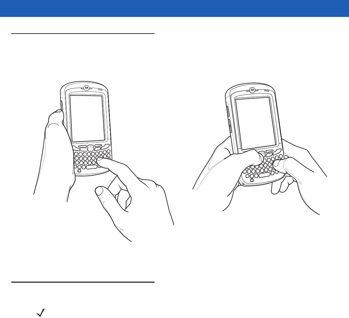
Entering Data
When entering data on the keypad, use either the single-hand method or the two-hand method as shown in
Figure 2-25.
Figure 2-25
Entering Data on the Keypad
Using Voice-Over-IP
The MC55 supports Voice over IP over WLAN (VoWLAN) using Motorola or third party voice clients. The MC55
can communicate using VoIP either using the MC55 supports several audio outputs, including back speaker
phone, front receiver or handset, and Bluetooth headset.
It is recommended that the wireless network use the 802.11a (5 GHz) band for voice applications. Using the 5
GHz band avoids some noise sources that may occur on the 802.11b/g (2.4 GHz) band due to wireless
interference.
When using a Bluetooth headset with the MC55 and VoWLAN, it is required to use the Bluetooth Headset
profile instead of Hands-free profile. Use the buttons on the MC55 to answer and end calls. See Chapter 4,
Bluetooth for information on setting up a Bluetooth Headset Profile.
Single-hand Method Two-hand Method
NOTE Voice-Over-IP is currently supported on the MC55A0. It will be supported on the MC55N0 in a
future update.

Operation 2 - 23
Interactive Sensor Technology
The Interactive Sensor Technology (IST) supports the following features:
•
Power Management – manages power by configuring IST to control switching on/off the backlight,
control suspend mode of the MC55 by monitoring motion and orientation.
•
Display Orientation – switches the screen orientation to either landscape or portrait depending on the
MC55 orientation.
•
Free Fall Detection – monitors free fall duration and records the time and type of the drop event.
Power Management
The MC55 orientation and motion sensitive data can be used as an indicator of MC55 usage and can be used
to manage the battery power of the mobile computer. For example, IST can be configured to control the
backlight on and off functionality or go into suspend according to a user gesture by placing screen facing down.
It can also be used to keep the MC55 active while it is in movement to prevent it from quickly going into
suspend mode while in use.
Display Orientation
The screen can be rotated between portrait and landscape modes automatically, depending on the physical
orientation of the MC55. For example, if the MC55 is rotated 90° counterclockwise, IST rotates the display
counterclockwise 90° so that the screen display appears correct.
This functionality is achieved by monitoring screen angle and rotating the display to counter any changes. IST
only rotates the screen in multiples of 90°.
Free Fall Detection
IST continuously monitors gravitational force on the MC55 according to its current position. When the MC55
free falls, IST detects the absence of gravitational force and records the event data if it detects a free fall more
than 450 ms, which may indicates nearly a one meter drop. This data can be used as an indicator of potential
abuse or misuse.
IST features a log for recording the free fall events. This log records the date, time and the time period of the
free fall.

2 - 24 MC55A0/MC55N0 Enterprise Digital Assistant User Guide
USB Configuration
The MC55 can be placed into any of the following USB modes:
•
USB Client - Sets the MC55 to USB Client mode.
•
USB Host - Sets the MC55 to USB Host mode.
•
USB On-the-Go - Sets the MC55 to automatically determine necessary mode (default).
To place the MC55 into one of these modes:
1. Tap > Settings > System > USBConfig.
2. Select on of the USB radio buttons.
3. Tap OK.

CHAPTER 3 DATA CAPTURE
Introduction
The MC55 offers three types of data capture options:
•
Linear scanning
•
Imaging
•
Digital camera.
Linear Scanning
MC55 with an integrated linear scanner have the following features:
•
Reading of a variety of bar code symbologies, including the most popular linear, postal, and 1-D code
types.
•
Intuitive aiming for easy point-and-shoot operation.
Imaging
MC55 with an integrated imager have the following features:
•
Omnidirectional reading of a variety of bar code symbologies, including the most popular linear, postal,
PDF417, and 2D matrix code types.
•
The ability to capture and download images to a host for a variety of imaging applications.
•
Advanced intuitive laser aiming cross-hair and dot aiming) for easy point-and-shoot operation.
The imager uses digital camera technology to take a digital picture of a bar code, stores the resulting image in
its memory, and executes state-of-the-art software decoding algorithms to extract the data from the image.
NOTE To perform data capture a scanning enabled application must be installed on the MC55. A sample
scanning application can be downloaded from the Motorola Support site at http://support.symbol.com.

3 - 2 MC55A0/MC55N0 Enterprise Digital Assistant User Guide
Operational Modes
MC55 with an integrated imager support three modes of operation, listed below. Activate each mode by
pressing the Scan button.
•
Decode Mode: In this mode, the MC55 attempts to locate and decode enabled bar codes within its field
of view. The imager remains in this mode as long as you hold the scan button, or until it decodes a bar
code.
•
Pick List Mode: This mode allows you to selectively decode a bar code when more than one bar code is
in the MC55’s field of view. To accomplish this, move the aiming crosshair or dot over the required bar
code to decode only this bar code. This feature is ideal for pick lists containing multiple bar codes and
manufacturing or transport labels containing more than one bar code type (either 1D or 2D).
•
Image Capture Mode: Use this mode to capture an image within the MC55’s field of view. This is useful
for capturing signatures or images of items like damaged boxes.
Digital Camera
MC55 with an integrated digital camera have the following features:
•
Omnidirectional reading of a variety of bar code symbologies, including the most popular linear, postal,
PDF417, and 2D matrix code types.
•
Advanced intuitive aiming for easy point-and-shoot operation.
The camera uses digital camera technology to take a digital picture of a bar code, stores the resulting image in
its memory, and executes state-of-the-art software decoding algorithms to extract the data from the image.
Scanning Considerations
Typically, scanning is a simple matter of aim, scan, and decode and a few quick trial efforts master it. However,
consider the following to optimize scanning performance:
•
Range
Any scanning device decodes well over a particular working range — minimum and maximum distances
from the bar code. This range varies according to bar code density and scanning device optics.
Scanning within range brings quick and constant decodes; scanning too close or too far away prevents
decodes. Move the scanner closer and further away to find the right working range for the bar codes
being scanned.
•
Angle
Scanning angle is important for promoting quick decodes. When laser beams reflect directly back into the
scanner from the bar code, this specular reflection can “blind” the scanner.
To avoid this, scan the bar code so that the beam does not bounce directly back. But don’t scan at too
sharp an angle; the scanner needs to collect scattered reflections from the scan to make a successful
decode. Practice quickly shows what tolerances to work within.
•
Hold the MC55 farther away for larger symbols.
•
Move the MC55 closer for symbols with bars that are close together.
NOTE To enable Pick List Mode, download the Control Panel applet from the Support Central web site at
http://support.symbol.com. Pick List can also be set in an application using a API command.
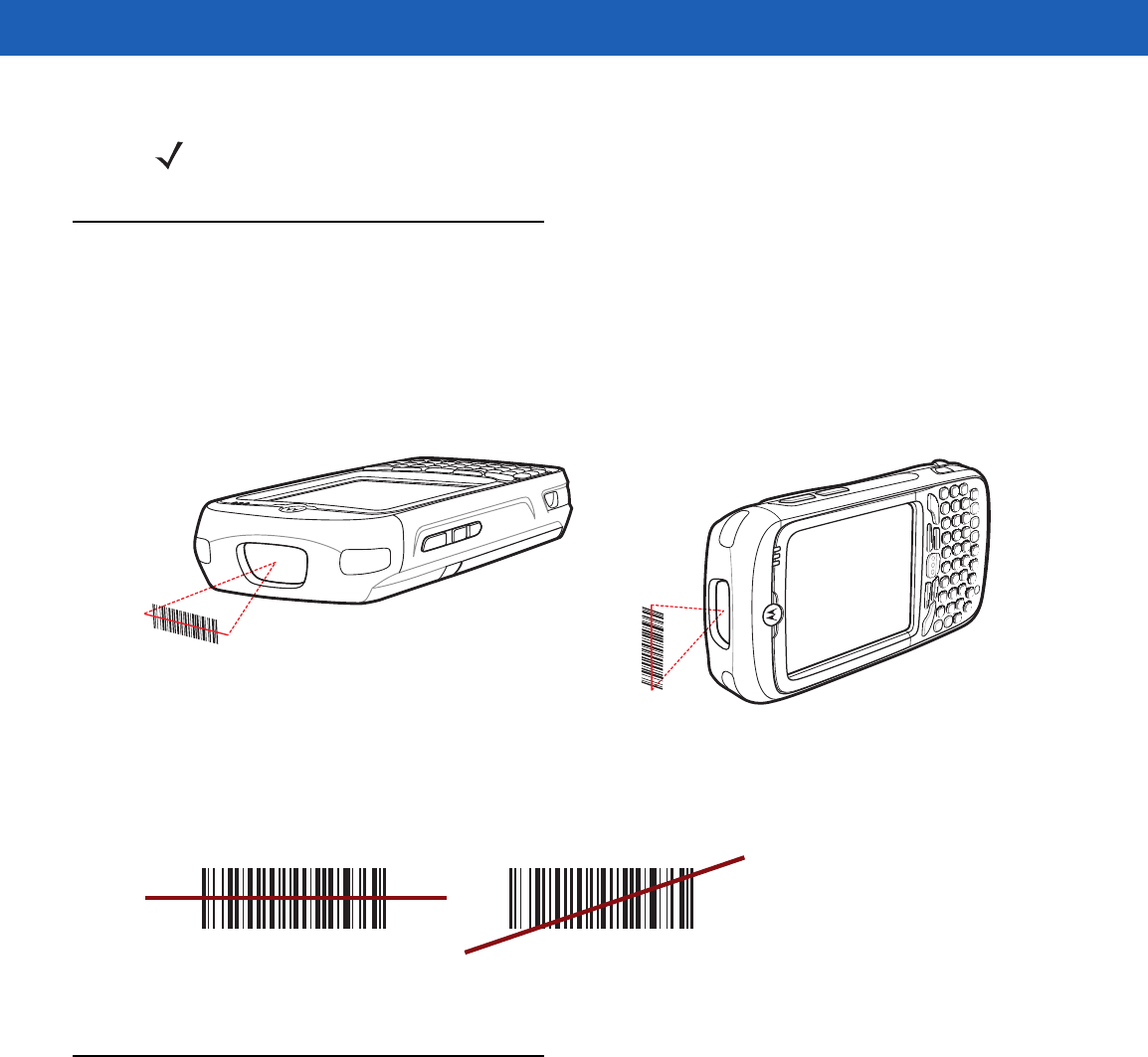
Data Capture 3 - 3
Linear Scanning
To read a bar code, a scan-enabled application is required. The MC55 contains the DataWedge application
that allows the user to enable the scanner to decode bar code data and display the bar code content.
1. Ensure that a scan enabled application (DataWedge) is loaded on the MC55. See DataWedge on page
3-6.
2. Aim the scan window at the bar code.
Figure 3-1
Linear Scanning
3. Press the scan button. Ensure the red scan beam covers the entire bar code. The Scan/Decode LED lights
red to indicate that scanning is in process, then lights green and a beep sounds, by default, to indicate the
bar code was decoded successfully.
Figure 3-2
Linear Scanner Aiming Pattern
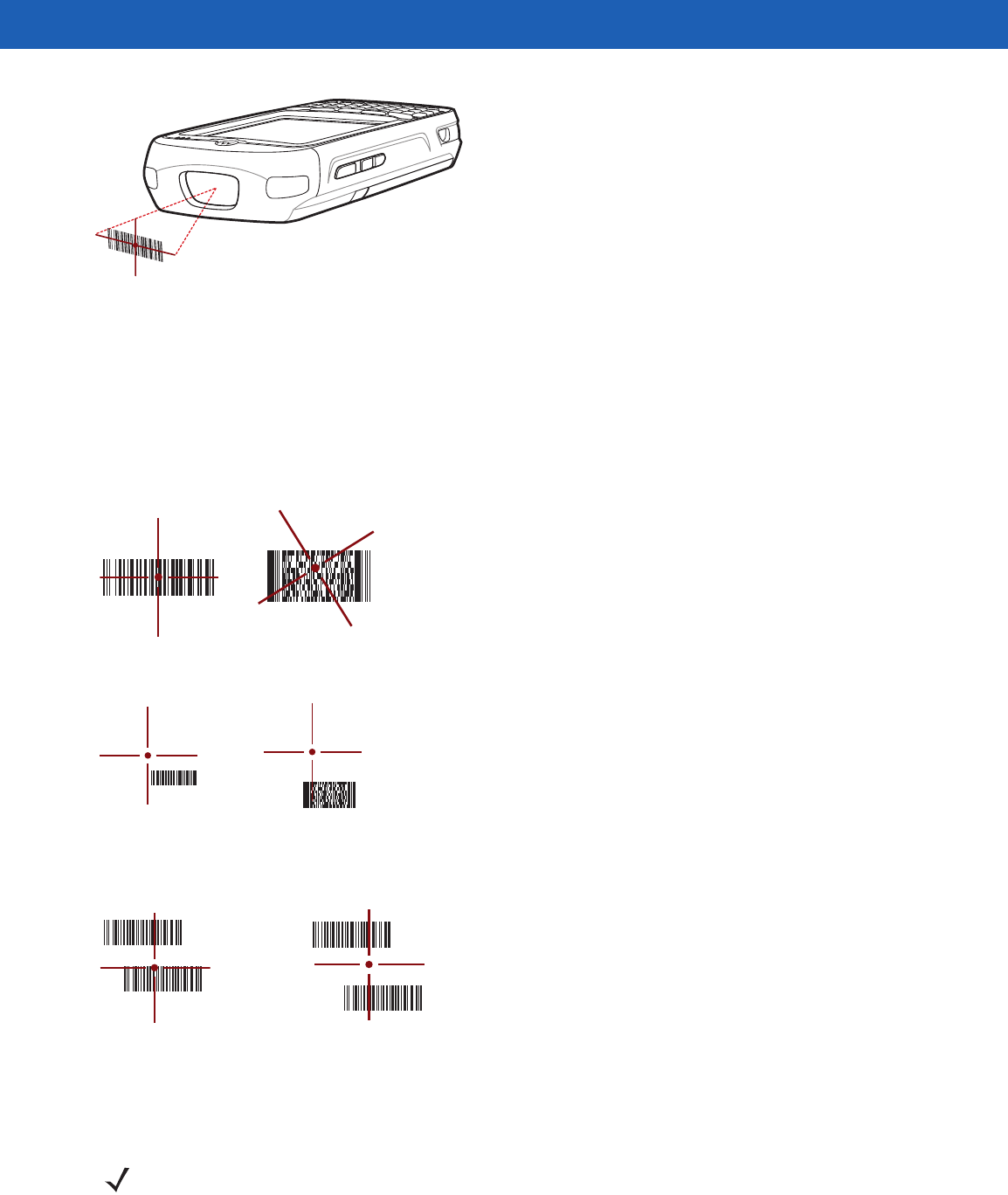
Imager Scanning
To read a bar code, a scan-enabled application is required. The MC55 contains the DataWedge application
that allows the user to enable the scanner to decode bar code data and display the bar code content.
1. Ensure that a scan-enabled application (DataWedge) is loaded on the MC55. See DataWedge on page
3-6.
2. Aim the scan window at the bar code.
NOTE Scanning procedures depend on the application and MC55 configuration. An application may use different
scanning procedures from the one listed above.
Correct Incorrect
3 - 4 MC55A0/MC55N0 Enterprise Digital Assistant User Guide
Figure 3-3
Imager Scanning
3. Press the scan button.
The red laser aiming pattern or aiming dot turns on to assist in aiming. Ensure the bar code is within the
area formed by the brackets in the aiming pattern or close to the aiming dot. The aiming dot is used for
increased visibility in bright lighting conditions.
The Scan/Decode LED lights red to indicate that scanning is in process, then lights green and a beep
sounds, by default, to indicate the bar code was decoded successfully. Note that when the MC55 is in Pick
List Mode, the imager does not decode the bar code until the crosshair or aiming dot touches the bar code.
Figure 3-4
Imager Aiming Pattern: Bar Code Centered
Figure 3-5
Imager Aiming Pattern: Bar Code Not Centered
Figure 3-6
Pick List Mode with Multiple Bar Codes in Aiming Pattern
4. Release the scan button.
Correct Incorrect
Decoded Not Decoded
NOTE Imager decoding usually occurs instantaneously. The MC55 repeats the steps required to take a digital
picture (image) of a poor or difficult bar code as long as the scan button remains pressed.
Data Capture 3 - 5
Using the RS507 Hands-free Imager
An RS507 Hands-free Imager can be used with the MC55 to capture bar code data.
To set up the MC55 and RS507:
1. Tap > BTScannerCtlPanel icon.
2. Select the BT Scanner checkbox and then select the appropriate Com port from the drop-down list.
3. Tap Save and Exit.
4. Tap > Display_BD_Address icon. A bar code displays.
5. Point the RS507 to the bar code. The RS507 reads the bar code and begins pairing with the MC55. If
required, enter PIN (12345).
6. Launch a scanning enabled application.
7. Point the RS507 at a bar code to read the bar code data.
Refer to the RS507 Hands-free Imager Product Reference Guide for more information.
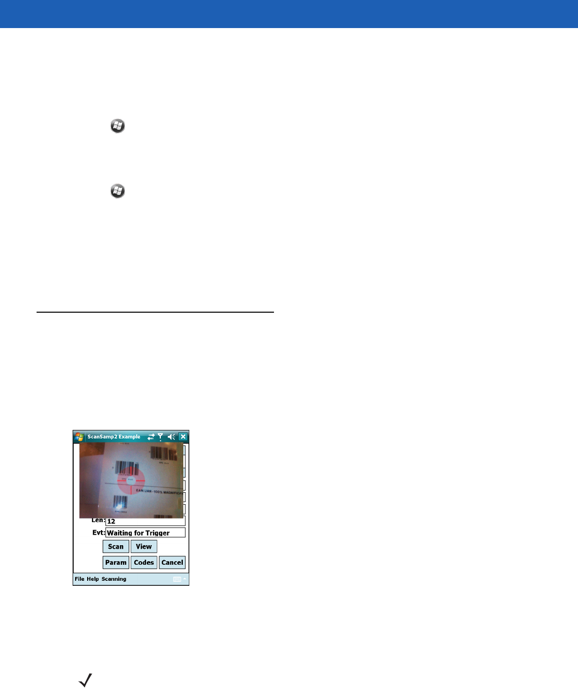
Digital Camera Scanning
1. Ensure that a scan-enabled application (DataWedge) is loaded on the MC55. See DataWedge on page
3-6.
2. Aim the camera lens on the back of the MC55 at a bar code.
3. Press and hold the scan button. A preview window appears on the display window with a red aiming reticle
in the center. The Scan/Decode LED lights red to indicate that scanning is in process.
Figure 3-7
Sample Scan Application with Preview Window
4. Move the MC55 until the red aiming reticle is over the bar code to scan.
5. The Scan/Decode LED lights green and a beep sounds, by default, to indicate the bar code was decoded
successfully.
NOTE The camera decode feature is set by default to automatically decode the bar code when read. This feature can
be programmed to display a green aiming rectile upon good decode indicating that the bar code has been
successfully decoded and to release the scan button.

3 - 6 MC55A0/MC55N0 Enterprise Digital Assistant User Guide
DataWedge
Installation
To install DataWedge:
1. Tap > File Explorer.
2. Navigate to the Windows folder.
3. Scroll to the DataWedge file.
4. Tap the DataWedge file. The installation begins. Follow the on-screen instructions to complete the
installation.
Enable DataWedge
To enable DataWedge:
1. Tap > Settings > System > DataWedge.
2. Tap Basic configuration.
3. Tap 1. Barcode input.
4. Tap one of the following:
a. 1. 1D Scanner Driver or 1. Block Buster Imager.
b. 2. Camera Scanner Driver
c. 3. Bluetooth SSI Scanner Driver
5. Ensure that a check mark is next to 1. Enabled. If not, tap 1. Enabled.
6. Tap 0. Back.
7. Tap 0. Back.
8. Tap 0. Exit and then tap OK.
9. Tap Running to start the DataWedge process. The DataWedge Status changes to Ready.
10. Tap OK.
Disable DataWedge
To disable DataWedge:
1. Tap > Settings > System > DataWedge.
2. Tap the Running option to end the DataWedge process. The DataWedge Status changes to Stopped.
NOTE On MC55N0, by default, DataWedge is loaded but not installed on the MC55. An installation file resides in
the Windows folder.
NOTE For MC55N0 only.

Data Capture 3 - 7
3. Tap OK.
Taking Photos
To take a photo:
1. Tap > Programs > Pictures & Videos icon.
2. Tap Camera on the command bar.
3. Check the image on the view finder, adjust if necessary.
4. Press the Enter key to take the picture. Hold the MC55 still until the shutter sound is heard.
Recording Video
To record a video clip:
1. Tap > Programs > Pictures & Videos icon.
2. Tap Camera on the command bar.
3. Tap Menu > Video to set shooting mode to video.
The available recording time displays on the screen.
4. Press the Enter key to begin recording.
Recording stops when you press the Enter button again.
Viewing Photos and Videos
To view photos and video clips:
1. Tap > Programs > Pictures & Videos icon.
2. Tap the picture or video clip to view.
NOTE By default, the time limit for recording videos is set to 30 seconds.

3 - 8 MC55A0/MC55N0 Enterprise Digital Assistant User Guide

CHAPTER 4 BLUETOOTH
Introduction
Bluetooth-equipped devices can communicate without wires, using frequency-hopping spread spectrum
(FHSS) radio frequency (RF) to transmit and receive data in the 2.4 GHz Industry Scientific and Medical (ISM)
band (802.15.1). Bluetooth wireless technology is specifically designed for short-range (30 feet/10 meters)
communication and low power consumption.
MC55s with Bluetooth capabilities can exchange information (e.g., files, appointments, and tasks) with other
Bluetooth enabled devices such as phones, printers, access points, and other mobile computers. To use the
MC55 as a modem, create a dial-up modem connection between a computer and MC55.
TheMC55 with Bluetooth technology uses either the StoneStreet Bluetooth stack or the Microsoft Bluetooth
stack. To write an application that uses the StoneStreet One Bluetooth stack APIs, refer to the Enterprise
Mobility Developer Kit (EMDK) Help.
Adaptive Frequency Hopping
Adaptive Frequency Hopping (AFH) is a method of avoiding fixed frequency interferers, and can be used with
Bluetooth voice. All devices in the piconet (Bluetooth network) must be AFH-capable in order for AFH to work.
There is no AFH when connecting and discovering devices. Avoid making Bluetooth connections and
discoveries during critical 802.11b communications. AFH for Bluetooth consists of four main sections:
•
Channel Classification - A method of detecting an interference on a channel-by-channel basis, or
pre-defined channel mask.
•
Link Management - Coordinates and distributes the AFH information to the rest of the Bluetooth network.
•
Hop Sequence Modification - Avoids interference by selectively reducing the number of hopping
channels.
•
Channel Maintenance - A method for periodically re-evaluating the channels.
When AFH is enabled, the Bluetooth radio “hops around” (instead of through) the 802.11b high-rate channels.
AFH coexistence allows Motorola mobile computers to operate in any infrastructure.

4 - 2 MC55A0/MC55N0 Enterprise Digital Assistant User Guide
The Bluetooth radio in this MC55 operates as a Class 2 device power class. The maximum output power is
2.5mW and the expected range is 32.8 feet (10 meters). A definition of ranges based on power class is difficult
to obtain due to power and device differences, and whether one measures open space or closed office space.
Security
The current Bluetooth specification defines security at the link level. Application-level security is not specified.
This allows application developers to define security mechanisms tailored to their specific need. Link-level
security occurs between devices, not users, while application-level security can be implemented on a per-user
basis. The Bluetooth specification defines security algorithms and procedures needed to authenticate devices,
and if needed, encrypt the data flowing on the link between the devices. Device authentication is a mandatory
feature of Bluetooth while link encryption is optional.
Pairing of Bluetooth devices is accomplished by creating an initialization key that is used to authenticate the
devices and create a link key for them. Entering a common PIN number in the devices being paired generates
the initialization key. The PIN number is never sent over the air. By default, the Bluetooth stack responds with
no key when a key is requested (it is up to user to respond to the key request event). Authentication of
Bluetooth devices is based-upon a challenge-response transaction. Bluetooth allows for a PIN number or
passkey that is used to create other 128-bit keys used for security and encryption. The encryption key is
derived from the link key used to authenticate the pairing devices. Also worthy of note is the limited range and
fast frequency hopping of the Bluetooth radios that makes long-distance eavesdropping difficult.
Recommendations are:
•
Perform pairing in a secure environment
•
Keep PIN codes private and don't store the PIN codes in the mobile computer
•
Implement application-level security.
The Microsoft stack supports Smart-pairing. For detailed information, refer to the Microsoft MSDN.
Security Mode 3 (Link Level Encryption)
The MC55 supports Security Level 3 (Link Level Encryption). Link level encryption is the data security process
of encrypting information at the data link level as it is transmitted between two devices.
Microsoft Bluetooth Stack
When pairing with a remote device using the Microsoft Bluetooth UI, Security Level 3 (Link Level Encryption) is
automatically used. When developing applications using the Microsoft Bluetooth stack, enable Security Mode 3
using the BthSetEncryption API call. Refer to the Microsoft MSDN for more information.
StoneStreet One Bluetooth Stack
To set Security Mode 3 on outgoing serial port connections, set Encrypt Link On All Outgoing Connections
checkbox in the Settings > Security. See Security on page 4-36 for more information.
NOTE It is not recommended to perform Bluetooth wireless technology inquiry when high rate 802.11b
operation is required.

Bluetooth 4 - 3
Bluetooth Configuration
By default, the MC55 is configured to using the Microsoft Bluetooth stack. Refer to the MC55 Integrator Guide,
Appendix B, for information on switching to the StoneStreet One Bluetooth stack.
Table 4-1 list the services supported by the Microsoft Bluetooth stack and the StoneStreet One Bluetooth stack.
Table 4-2 list the COM ports available for the StoneStreet One Bluetooth stack and the Microsoft Bluetooth
stack.
Table 4-1
Bluetooth Services
Microsoft Bluetooth Stack StoneStreet One Bluetooth Stack
Dial-Up Networking Services File Transfer Services
OBEX Object Push Services Dial-Up Networking Services
PBAP Services OBEX Object Push Services
Serial Port Services Headset Audio Gateway Services
Personal Area Networking Services Serial Port Services
A2DP/AVRCP Services Personal Area Networking Services
HID Host Services
A2DP/AVRCP Services
Table 4-2
COM Ports
Microsoft Bluetooth Stack StoneStreet One Bluetooth Stack
COM5 COM5
COM9 COM9
COM11
COM21
COM22
COM23

4 - 4 MC55A0/MC55N0 Enterprise Digital Assistant User Guide
Bluetooth Power States
Cold Boot
With StoneStreet One Bluetooth Stack
Performing a cold boot on the MC55 turns off Bluetooth after initialization (which takes a few moments). It is
normal to see the Bluetooth icon appear and disappear (when using the Classic Home screen), as well as a
wait cursor, when initialization proceeds in all modes.
With Microsoft Bluetooth Stack
Performing a cold boot retain the state of the Bluetooth radio prior to the cold boot.
Warm Boot
With StoneStreet One Bluetooth Stack
Performing a warm boot on the MC55 turns off Bluetooth.
With Microsoft Bluetooth Stack
Performing a warm boot retain the state of the Bluetooth radio prior to the warm boot.
Suspend
When there is an active Bluetooth connection, the Bluetooth radio goes into low power mode maintaining the
active connection. When there is no active connection, the Bluetooth radio turns off.
With StoneStreet One Bluetooth Stack
With Microsoft Bluetooth Stack
Resume
When the MC55 resumes, Bluetooth turns on if it was on prior to suspend.
NOTE If there is an active Bluetooth connection between the MC55 and another Bluetooth device, the MC55 will
not timeout. However, if the user presses the Power button on the MC55, the MC55 will suspend and
upon receiving data from a remote Bluetooth device, the MC55 will wake from suspend mode. For
example, Bluetooth scanner sending data to the MC55.
NOTE If there is an active Bluetooth connection between the MC55 and another Bluetooth device and there is
no data activity, the MC55 will timeout. However, if the user presses the Power button on the MC55, the
MC55 will suspend and upon receiving data from a remote Bluetooth device, the MC55 will wake from
suspend mode. For example, Bluetooth scanner sending data to the MC55.
Bluetooth 4 - 5
Using Microsoft Bluetooth Stack
The following sections provide information on using the Microsoft Bluetooth stack.
Turning the Bluetooth Radio Mode On and Off
Turn off the Bluetooth radio to save power or if entering an area with radio restrictions (e.g., an airplane). When
the radio is off, other Bluetooth devices cannot see or connect to the MC55. Turn on the Bluetooth radio to
exchange information with other Bluetooth devices (within range). Communicate only with Bluetooth radios in
close proximity.
Enabling Bluetooth
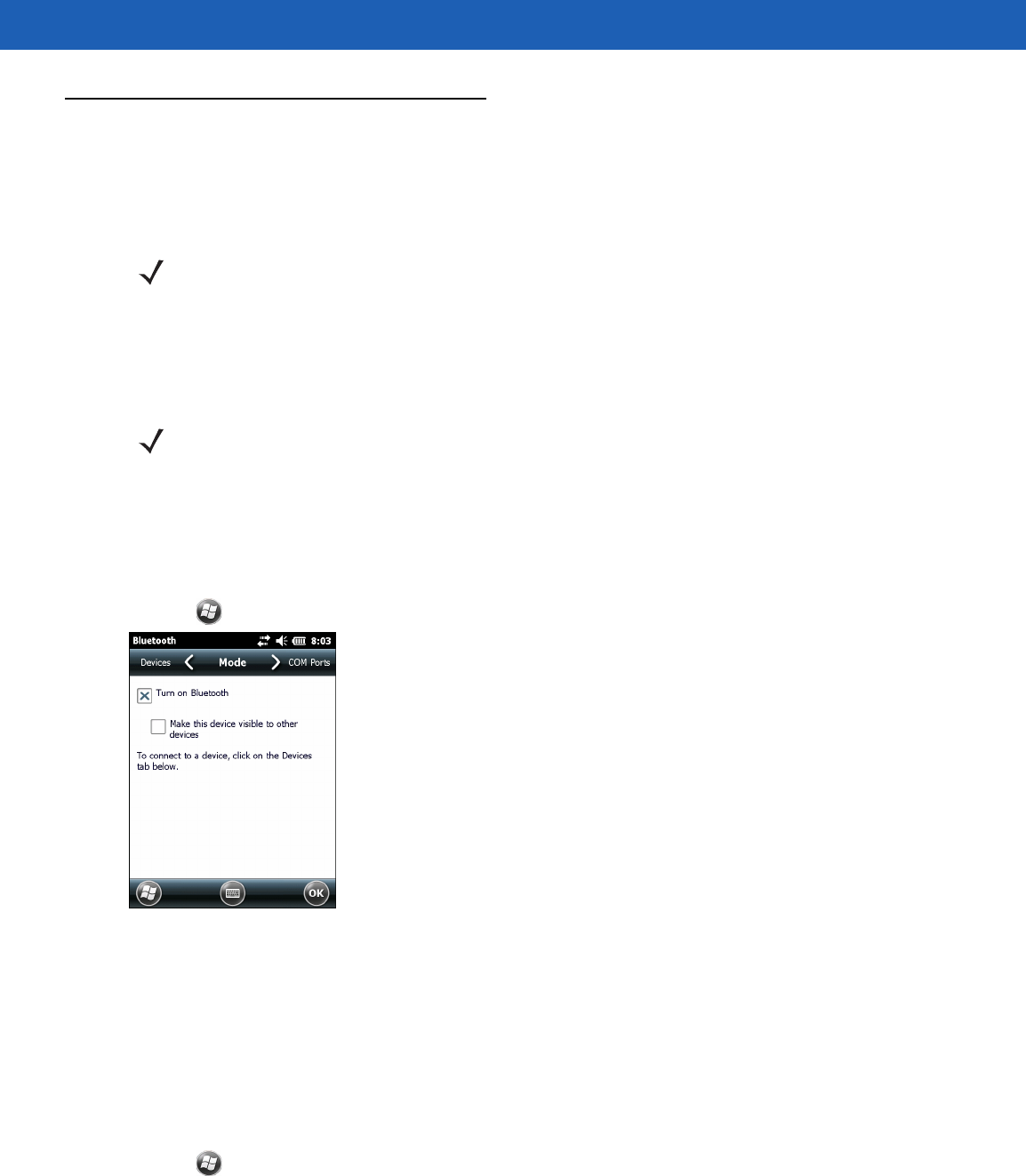
To enable Bluetooth:
1. Tap Wireless Manager and then tap the Bluetooth bar or
Tap > Setting > Connections > Bluetooth icon > Mode.
Figure 4-1
Bluetooth Mode
2. Check the Turn On Bluetooth checkbox.
3. Tap OK.
Disabling Bluetooth
To disable Bluetooth:
1. Tap Wireless Manager and then tap the Bluetooth bar or
Tap > Setting > Connections > Bluetooth icon > Mode.
2. Un-check the Turn On Bluetooth checkbox.
3. Tap OK.
NOTE On devices with Windows Mobile 6.5.3, turn the Bluetooth radio on or off using the Wireless Manager.
Tap the Status bar and select the Connectivity icon. Tap Wireless Manager.
NOTE To achieve the best battery life turn off radios not in use.
4 - 6 MC55A0/MC55N0 Enterprise Digital Assistant User Guide
Discovering Bluetooth Device(s)
The MC55 can receive information from discovered devices without bonding. However, once bonded, the
MC55 and a bonded device exchange information automatically when you turn the Bluetooth radio on. See
Bonding with Discovered Device(s) on page 4-30 for more information.
To find Bluetooth devices in the area:
1. Ensure that Bluetooth is enabled on both devices.
2. Ensure that the Bluetooth device to discover is in discoverable and connectable modes.
3. Ensure that the two devices are within 30 feet (10 meters) of one another.
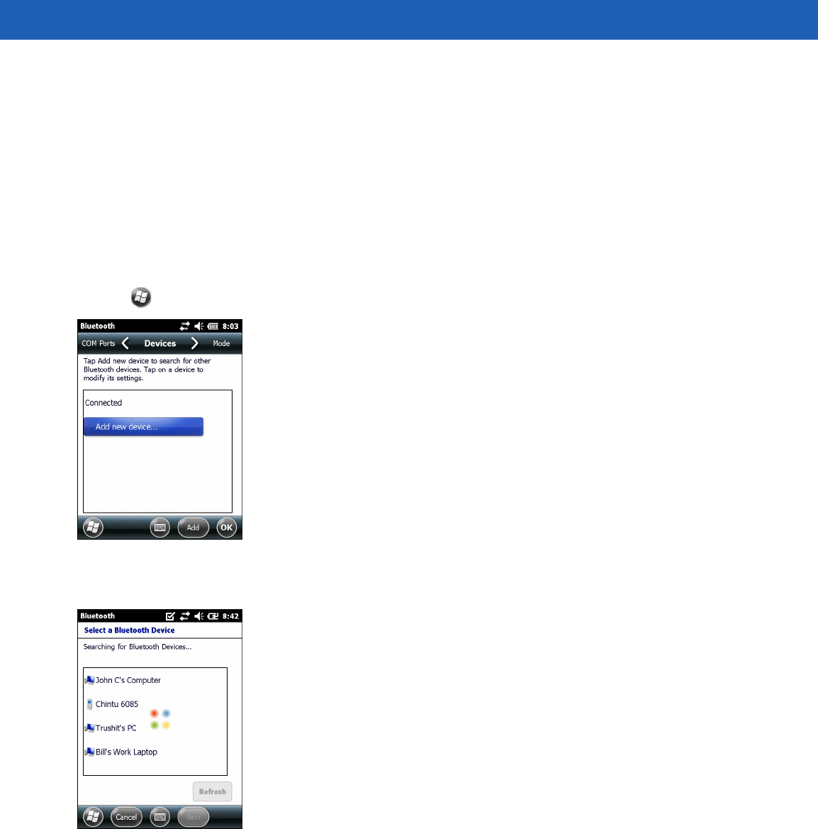
4. Tap > Settings > Connections > Bluetooth > Devices.
Figure 4-2
Bluetooth - Devices
5. Tap Add new device. The MC55 begins searching for discoverable Bluetooth devices in the area.
Figure 4-3
Searching for Bluetooth Devices
6. Select a device from the list.