Zebra Technologies WMC6300704 PCMCIA Card User Manual MEA Setup and Deployment User s Guide
Zebra Technologies Corporation PCMCIA Card MEA Setup and Deployment User s Guide
Contents
MEA Setup and Installation Guide

Setup and Installation
Guide
Version 3.0
Copyright 2003-2004, MeshNetworks, Inc. All Rights Reserved

MEA Setup and Installation
Foreword
This document describes in detail the confidential and proprietary technology of MeshNetworks’
MEA™ Architecture. MeshNetworks products and technology are protected by US and
international patent and patent pending technology. This document represents the current MEA
design; the contents are subject to change at any time at the discretion of MeshNetworks, Inc.
MEA, MeshManager, MeshTray, MeshView, and MeshNetworks’ logo are trademarks or
registered trademarks of MeshNetworks, Inc. Microsoft, Windows, Windows 2000, and
Windows PocketPC are registered trademarks of Microsoft Corporation. Sun and Sun Blade
are registered trademarks of Sun Microsystems, Inc. All other product names and services
identified throughout this publication are trademarks or registered trademarks of their respective
companies. No such uses or the use of any trade name is intended to convey endorsement or
other affiliation with this publication.
Copyright © 2003-2004, MeshNetworks, Inc. All Rights Reserved.
i

MEA Setup and Installation
Table of Contents
SECTION 1 - OVERVIEW ............................................................................................................1
Introduction .......................................................................................................................... 1
Documentation Overview.................................................................................................... 1
Acronyms ............................................................................................................................. 2
Related Documentation..................................................................................................... 2
SECTION 2 - DESCRIPTION OF THE MEA SYSTEM ................................................................ 3
Introduction .......................................................................................................................... 3
Subscriber Devices (SDs) ...................................................................................................4
Wireless Routers (WRs) ...................................................................................................... 4
Intelligent Access Points (IAPs) ......................................................................................... 5
VMM6300 - Vehicle Mounted Modem ................................................................................. 5
EWR6300 - Enhanced Wireless Router.............................................................................. 6
PWR6300 Portable Wireless Router................................................................................... 6
Mobile Internet Switching Controller (MiSC)..................................................................... 7
Operational View of the MEA System ................................................................................ 8
Network Architecture...........................................................................................................9
Unified Modes of Operation ................................................................................................ 9
Network DHCP Scheme..................................................................................................10
Statically Provisioned Scheme........................................................................................10
User Supplied Scheme ...................................................................................................10
Quality of Service (QoS) and User Priority Features...................................................... 13
Quality of Service............................................................................................................14
User Priority ....................................................................................................................14
SECTION 3 - SETUP AND INSTALLATION................................................................................ 1
iii

MeshNetworks
Subscriber Device (SD) .......................................................................................................1
Equipment.........................................................................................................................1
Record MAC Address of the WMC6300 ...........................................................................1
Loading and Verifying WMC6300 Software ......................................................................1
Testing ..............................................................................................................................4
Intelligent Access Point (IAP) ............................................................................................. 4
Equipment.........................................................................................................................4
Record MAC Address of the IAP.......................................................................................6
IAP Assembly....................................................................................................................6
Deployment.......................................................................................................................8
Initial IAP Configuration.....................................................................................................9
Testing ..............................................................................................................................9
Wireless Router (WR) ........................................................................................................ 10
Equipment.......................................................................................................................10
Record MAC Address of the MWR6300 .........................................................................11
MWR6300 Assembly.......................................................................................................11
Deployment.....................................................................................................................12
Initial Configuration .........................................................................................................12
Testing ............................................................................................................................12
Mobile Internet Switching Controller (MiSC)................................................................... 12
Equipment.......................................................................................................................12
Network Setup Description..............................................................................................14
MiSC Assembly...............................................................................................................15
Upgrade MiSC/DHCP Configuration (optional) ............................................................... 15
Changing the Wireless Subnet........................................................................................16
Onsite Configuration of Routers......................................................................................17
iv

MEA Setup and Installation
Network Configuration – Device Manager ......................................................................18
Network Configuration – IAP Configuration Via Web Interface.......................................18
Testing ............................................................................................................................34
Default Addresses and Logins ........................................................................................35
SECTION 4 - MAC ADDRESS TABLES.................................................................................... 37
IAP MAC Addresses .......................................................................................................... 37
WR MAC Addresses .......................................................................................................... 37
WMC MAC Addresses ....................................................................................................... 38
SECTION 5 - SITE SELECTION/DEPLOYMENT GUIDELINES ............................................... 39
General Site Selection Guidelines.................................................................................... 39
Antenna Guidelines ........................................................................................................... 39
Lab Checkout ..................................................................................................................... 40
General Deployment Guidelines....................................................................................... 40
SECTION 6 - CUSTOMER SERVICE INFORMATION .............................................................. 42
SECTION 7 - LICENSE AND WARRANTY INFORMATION ..................................................... 43
SECTION 8 - FCC REGULATORY INFORMATION .................................................................. 48
FCC Information.................................................................................................................48
FCC RF Radiation Exposure Statement........................................................................... 48
SECTION 9 - SAFETY INFORMATION FOR THE MEA PRODUCTS ...................................... 49
SECTION 10 - SAFETY CERTIFICATION................................................................................. 49
CE Mark Certification......................................................................................................... 49
v

MeshNetworks
List of Figures
Figure 1. Elements of the MEA System.................................................................................3
Figure 2. Operational View of the MEA System....................................................................8
Figure 3. MEA Network Architecture .................................................................................9
Figure 4. Control Panel – Network and Dial-up Connections Icon ...................................11
Figure 5. Network and Dial-up Connections Window ........................................................12
Figure 6. Local Area Connection Properties Dialog Box..................................................12
Figure 7. Internet Protocol (TCP/IP) Properties Dialog Box ..............................................13
Figure 8. WMC6300 Antenna Port and LED Indicators ........................................................1
Figure 9 IAP6300 Identification Label...................................................................................6
Figure 10. IAP6300 Connection Points................................................................................6
Figure 11. IAP6300 Bracket ..................................................................................................7
Figure 12. Bracket Adjustment Bolts...................................................................................8
Figure 13. MWR6300 Identification Label..........................................................................11
Figure 14. MWR6300 External Connection Points............................................................11
Figure 15. Basic MiSC Configuration ................................................................................14
Figure 16 MEA Subnet Data...............................................................................................16
Figure 17. MEA Device Administration Connection.........................................................18
Figure 18. MEA Device Administration Logon Window..................................................18
Figure 19. MEA Device Administration Authentication Window.....................................19
Figure 20. MEA Device Administration Home Tab ...........................................................20
Figure 21. MEA Device Administration Enter New Password Window ..........................21
Figure 22. MEA Device Administration Confirmation Window .......................................22
Figure 23. MEA Device Administration Password Changed Window ............................22
Figure 24. MEA Device Administration Logon Window...................................................23
Figure 25. MEA Device Administration Update Device Firmware Window ....................23
Figure 26. MEA Device Administration Choose File Window .........................................24
Figure 27. MEA Device Administration Update Device Firmware Window (2)...............25
vi

MEA Setup and Installation
Figure 28. MEA Device Administration Update Confirmation Window ..........................25
Figure 29. MEA Device Administration Update Device Status Window .........................26
Figure 30. MEA Device Administration Restore Factory Defaults Window ...................27
Figure 31. Restore Factory Defaults Confirmation Message ..........................................27
Figure 32. MEA Device Administration Factory Settings Restored Window .................28
Figure 33 MEA Device Administration Device Reset Window .......................................29
Figure 34. MEA Device Administration Device Reset Window .......................................30
Figure 35. MEA Device Administration Device Reset Window (2) ..................................31
Figure 36. MEA Device Administration System Settings Tab .........................................32
Figure 37. System Settings Confirmation Message.........................................................33
Figure 38. System Settings Saved Message.....................................................................33
Figure 39. MEA Device Administration Associations Tab...............................................34
Figure 40. Antenna Mounting.............................................................................................40
vii

MEA Setup and Installation
Section 1 - Overview
Introduction
The MEA wireless broadband system allows a network operator to deploy a wireless, multi-
hopping ad hoc network. This document describes how to setup, configure, and deploy a MEA
system to operate in infrastructure mode.
The MEA system is designed for easy installation. The infrastructure components of a MEA
system are preinstalled with a default configuration for connection to a wired network. Any
configuration items described in this document are for site-specific information.
MeshNetworks recommends that the Network Operator receive setup and deployment training
at MeshNetworks’ facility prior to deploying the MEA network. MeshNetworks may optionally
provide the Network Operator assistance with site surveys and deployment.
Note: The MEA MWR6300 Wireless Routers and IAP6300 Intelligent Access Points require
professional installation to ensure the installation is performed in accordance with FCC licensing
regulations.
Documentation Overview
The MEA Setup and Deployment User’s Guide is arranged in the following sections:
Section 1 - Overview provides an overview of the MEA Starter Kit and the organization of the
User’s Guide.
Section 2 – Description of the MEA System provides a general overview of a complete MEA
Network.
Section 3 - Starter Kit Setup and Deployment provides installation and configuration
information for the Subscriber Device, Wireless Router, Intelligent Access Point, and the MiSC.
Section 4 - MAC Address Tables provides three convenient tables to record network
configuration data.
Section 5 – Site Selection Guidelines provides deployment and installation suggestions.
Section 6 - The Customer Service Information section provides contact information if you
need assistance with your MEA Starter Kit.
Section 7 - License and Warranty Information contains MeshNetworks’ License Agreement
and Warranty for the MEA products.
Section 8 - FCC Regulatory Information provides important warnings and safety information.
1

MeshNetworks
Acronyms
HAS Hardware Authentication Server
IAP Intelligent Access Point
MEA Mesh Enabled Architecture
MiSC Mobile Internet Switching Controller
SD Subscriber Device (a host device with a WMC6300 installed and operational)
WMC Wireless Modem Card
WR Wireless Router
PWR Portable Wireless Router
VMM Vehicle Wireless Router
EWR Enhanced Wireless Router
Related
Documentation
MEA WMC6300 Wireless Modem Card User’s Guide for Windows 2000
MEA WMC6300 Wireless Modem Card User’s Guide for Windows XP
MeshView Administration Tool User’s Guide
MeshManager User’s Guide
MeshFlash User’s Guide
Location Analyzer Deployment Tool User’s Guide
2
MEA Setup and Installation
Section 2 - Description of the MEA System
Introduction
MeshNetworks develops Mobile Broadband communications systems with ad hoc architectures.
That is, each node can connect directly, or indirectly (by hopping through other nodes), with any
other node in the network. The peer-to-peer nature of the ad hoc architecture combined with
data rate control in each subscriber and infrastructure node in the network insures reliable
delivery while providing increased network capacity through geographic reuse of the frequency
spectrum.
The network is comprised of following distinct elements:
• Subscriber Devices (SDs) and Vehicle Mounted Modems (VMMs)
• Wireless Routers (WRs), Enhanced Wireless Routers (EWRs) and Portable
Wireless Routers (PWRs)
• Intelligent Access Points (IAPs)
• Mobile Internet Switching Controllers (MiSCs)
Additional SD and infrastructure components are described separately.
The overwhelming portion of the value that MeshNetworks provides is in the Wireless Modem
Card (WMC). The WMC functionality is used in Subscriber Devices as well as in the Wireless
Router and Intelligent Access Point (IAP), both of which are types of infrastructure equipment.
MeshNetworks provides a Mobile Internet Switching Controller (MiSC) which is assembled from
industry standard equipment and conforms to industry standards. MeshNetworks also provides
the network applications, which are required for proper operation and value extraction from the
MEA mobile Internet system.
Figure 1. Elements of the MEA System
3
MeshNetworks
All network elements are designed to support mobile applications. Subscriber Devices can be
either mobile or fixed, while the remaining components are typically fixed. Wireless Routers and
IAPs can be mounted on utility poles, light poles, traffic apparatus, billboards, and buildings.
Their fixed positions allow the Subscriber Device to pinpoint its location within one second.
WRs and IAPs can also be mobile, attached to emergency vehicles, utility vehicles, or fleet
vehicles. It is important to note that the WMC technology within a Subscriber Device is identical
to the WMC technology in Wireless Routers and IAPs.
The MEA system was designed to minimize the cost associated with deploying a broadband
mobile network with end user data access rates on the order of DSL or Cable Modem. The
chosen metric of network efficiency for a data centric network is bits per second per Hertz per
square kilometer per dollar (bps/hz/km2/$). This metric balances the user data rates, allocated
bandwidth, coverage area, and cost.
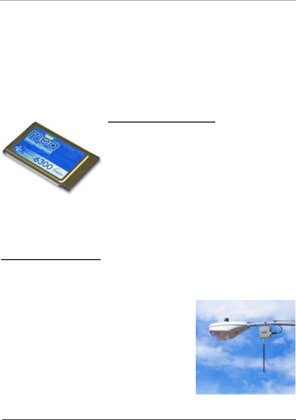
Subscriber Devices (SDs)
The MeshNetworks’ Wireless Modem Card (WMC) is
provided as a PCMCIA form factor device. The WMC is
used with an off-the-shelf IP-enabled laptop computer or
PDA. These two devices together make up a Subscriber
Device (SD).
The WMC provides access to the fixed infrastructure network
and other networks, such as the Internet, and it can also
function as a Wireless Router and repeater for other SDs.
rt of thSDs can therefore be a key pa e network infrastructure. Adding subscribers can
Wireless Routers (WRs)
effectively increase the number of Wireless Routers in the network, which increases the number
of alternative paths that subscribers may utilize. This can reduce both the time and cost to
deploy network infrastructure, while also increasing the spectral efficiency and therefore the
capacity of the network. In addition, because SDs can also operate in an ad hoc peer-to-peer
mode, two or more SDs can form a network without the need for any fixed infrastructure.
-cost small-sized wireless device that is primarily deployed to
criber Devices and IAPs
optimization through small
ion
The Wireless Router's small size and light weight allow it to
be mo te ed. WR
The Wireless Router (WR) is a low
seed a geographical area, extending the range between IAPs and subscribers, and to
simultaneously increase the network’s spectral efficiency. Wireless Routers provide a number
of functions in the network, such as:
• Range Extension for Subs
• Automatic Load Balancing
• Route Selection
• Network capacity
packet consolidat
• Fixed reference for geo-location services
un d almost anywhere. No towers are requir
software can be updated via over-the-air downloads.
4
MEA Setup and Installation
Intelligent Access Points (IAPs)
The Intelligent Access Point (IAP) is a low-cost, small device that
acts as the transition point from the wireless network to the wired
core network and from there, through media gateways, out to the
Internet. Each IAP offers up to 6 Mbps burst data rate to
subscribers. IAPs support the 10/100 base-T Ethernet interface.
Other interfaces are supported through commercially available
media translation devices. If additional network capacity is
required, more IAPs can be easily deployed - without the need for
extensive RF or site planning. IAPs provide functions such as:
• Local mobility management of SDs
• Fixed reference for geo-location services
• Hopping points for subscriber peer-to-peer networking
• Transition point from the wireless to the wired portions
of the network
• Route Selection
The IAP’s small size and lightweight allow it to be mounted anywhere power and network
connectivity is available. No towers are required. The IAP software can be updated via over-
the-wire downloads.
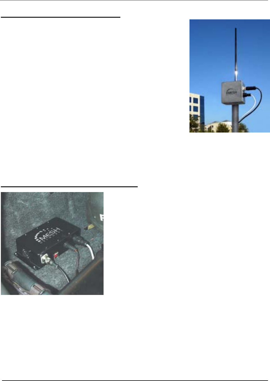
VMM6300 - Vehicle Mounted Modem
Compact and ruggedly designed, the MeshNetworks
Vehicle Mounted Modem (VMM) turns a vehicle into a
mobile office. Mobile Data Terminals (MDT), IP video
cameras, and other IP ready devices can access a high-
speed, mobile broadband network via a standard RJ45
Ethernet Port. This low cost, high performance, wireless
modem supports up to 6 Mbps burst data rates at
speeds of over 100 mph.
The VMM provides high bandwidth access to mission-
critical information on the move. Remote database
inquiries, on-scene report submission, multi-megabyte
file transfers and live video streams will make field
personnel more efficient. The VMM also supports real-
time position location without relying on GPS.
Like all MEA products, the VMM acts as a wireless router/repeater – automatically extending the
range, robustness and performance of the wireless network.
5
MeshNetworks
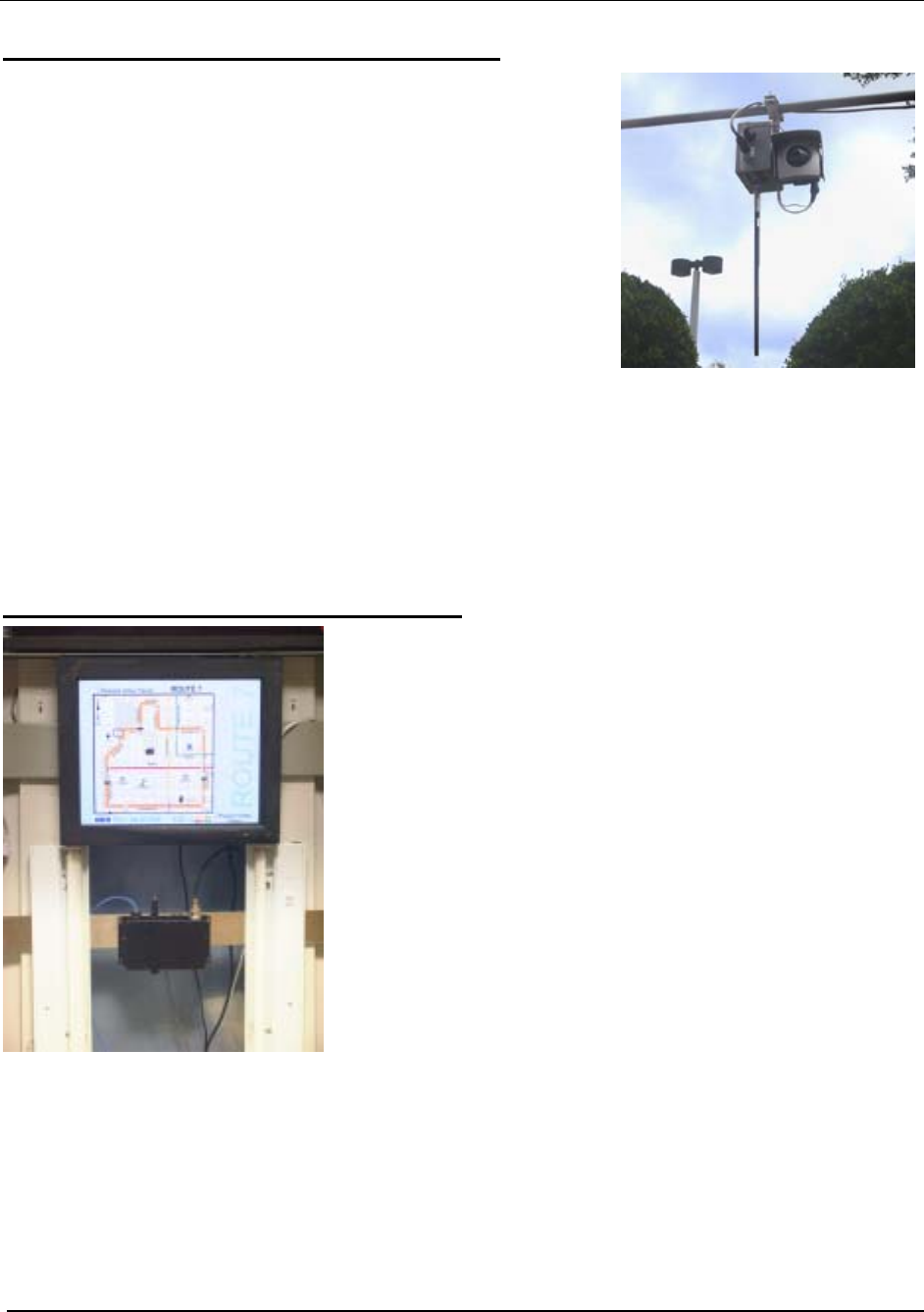
EWR6300 - Enhanced Wireless Router
The Enhanced Wireless Router (EWR) is deployed to
guarantee wireless coverage in large geographic areas while
providing wireless network access to one or more IP devices
via its built-in RJ45 Ethernet port. The EWR efficiently
combines the functionality of a MeshNetworks Wireless Router
and client modem in a single, cost-effective, wireless network
component. This makes it easy for any Ethernet ready device
to access a Mesh-Enabled Architecture (MEA) mobile
broadband network. Computers, IP video cameras (as
pictured at right), sensors, signs, signals, etc. can all be Mesh-
Enabled to send and receive data at burst rates of up to 6
Mbps. All of the standard Wireless Router functionality,
including Multi-Hopping, non-line-of-sight communications and position location services, is fully
supported. EWRs also provide:
• Range extension between clients an IAPs
• Fixed reference points between clients and IAPs
• Up to three assignable IP addresses
PWR6300 Portable Wireless Router
The PWR6300 Portable Wireless Router (PWR) has the
same functionality as the EWR, but in a smaller form factor
like the VMM. It combines the functionality of a Wireless
Router and the Wireless Modem Card into a single device.
By adding an Ethernet port to a Wireless Router,
MeshNetworks enables video cameras, computers or any
other Ethernet-capable device to get high-speed access to
the MEA wireless broadband network, without the need to
purchase a separate Wireless Modem Card. The PWR also
provides the same functionality as the MWR, including
network routing, Multi-Hopping™ and geo-location services.
• Range extension between clients an IAPs
• Fixed reference points between clients and IAPs
• Up to three assignable IP addresses
6

MEA Setup and Installation
Mobile Internet Switching Controller (MiSC)
The Mobile Internet Switching Controller (MiSC) provides
connectivity between the IAPs and the wired world, and
hosts the network’s management and provisioning
functions. The MiSC is composed of off-the-shelf
hardware components, such as LAN routers and
application servers. MiSC software consists of both off-
the-shelf and MeshNetworks’ proprietary software,
MeshManager. The MeshManager software provides
functions for the network such as:
• Subscriber Provisioning, Management, and
Authentication
• Configuration and Fault Management
• Network Monitoring and Reporting
7
MeshNetworks
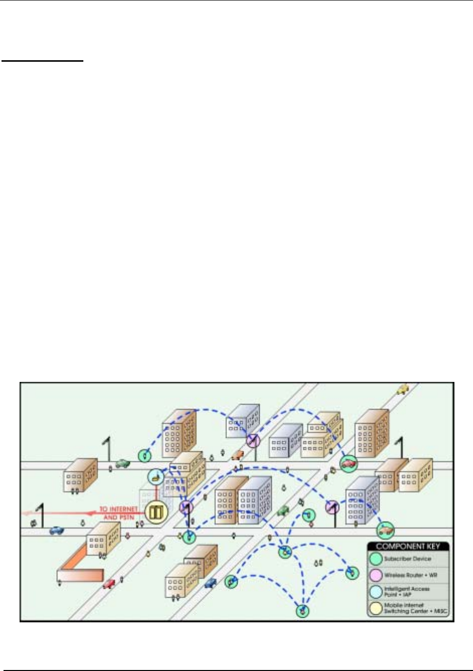
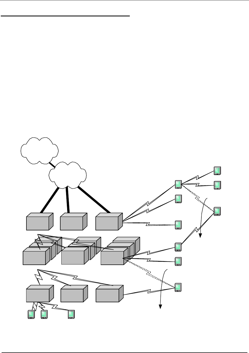
Operational View of the MEA System
Figure 2 shows the different ways a subscriber can reach an IAP. It can connect directly, or hop
through any number or combination of WRs and SDs. Additionally, if the subscriber wishes to
execute a peer-to-peer application such as a file transfer, the subscriber can communicate
directly, or through any combination of SDs, WRs, and IAPs.
The ability to use ad hoc routing to forward traffic improves the scalability of the mobile wireless
network. In particular, the ability for the user to accomplish a peer-to-peer application without
the use of infrastructure has tremendous advantages.
A significant problem in every mobile wireless network is backhaul. The MEA architecture
provides the ability to route traffic from applications through SDs and WRs without ever reaching
an IAP or the wired network. This reduces the amount of backhaul required by enabling the
SDs to accomplish the backhaul whenever the opportunity arises. In turn, this results in lower
deployment costs, reduced backhaul, and lower operating expenditures. The service provider
can provide the same level of service with less equipment by empowering the SDs with ad hoc
networking capability.
WR 1
WR 2
WR k2
WR k1
WR 1
. . .
. . .
T1
T1
. . .
T1
. . .
SD 2
SD 1
SD 1
. . .
SD 2
SD 1
SD 2
. . .
SD 2
SD 1
SD 3
. . .
. . .
SD 2
SD 1
SD 4
. . .
MiSC
IAP
WR
SD
Handoff
Handoff
Router Mesh
Mobile Internet Switching Controller
Intelligent Access Point
W ire l e ss Router
Subscriber Device
MiSC
Global
Internet
IA P 1
IA P 2
IA P N
WR 2
Figure 2. Operational View of the MEA System
8
MEA Setup and Installation
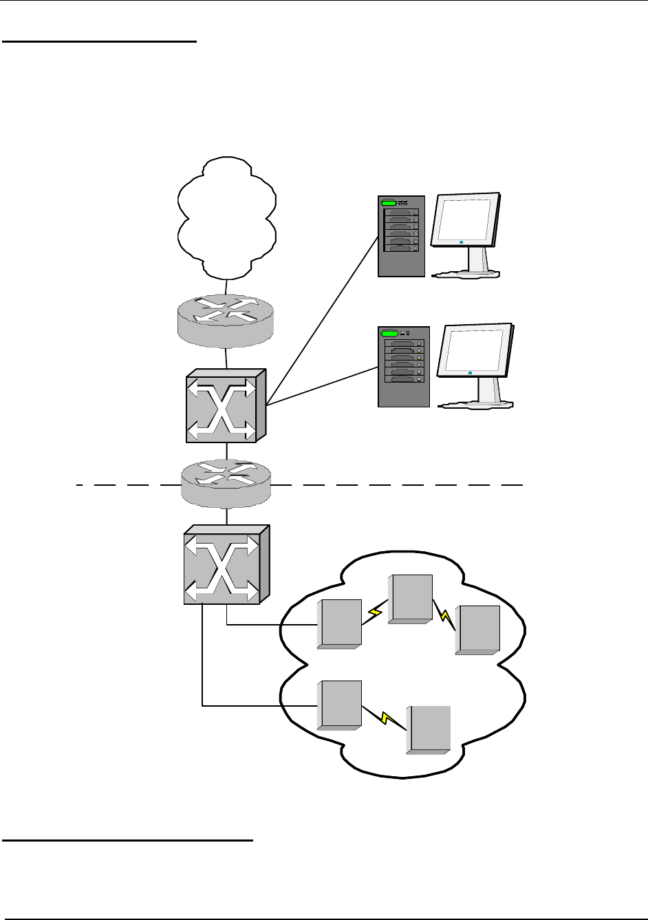
Network Architecture
The basic MEA network utilizes two subnets, one for the MEA wireless elements and one for the
server elements. For seamless IAP mobility, all of the MEA wireless elements must be in the
same subnet. The subnets are connected together by the core router, and the edge router
provides Internet connectivity.
Figure 3 shows the logical network layout of a MEA network.
core router
edge router
Internet
server
switch
wireless
switch
MeshManager
server
`
other servers
mēa
wireless
domain
IAP1
IAPn
. . .
WR
SD
SD
server subnet
wireless
subnet
Figure 3. MEA Network Architecture
Unified Modes of Operation
With MEA Release 3.0, the concept of modes has been replaced by unified modes of operation
addressing scheme. The concept of unified modes of operation centers on the current state of network
communication: Associated State and Unassociated State. There are three addressing schemes that
allow the IT manager increased flexibility in deployment.
9

MeshNetworks
Network DHCP Scheme
Operation under the Network DHCP scheme is similar to that of MEARelease 2 in Infrastructure
Mode. The primary difference is that users are now allowed to temporarily wander outside the
network infrastructure without losing connectivity.
Network DCHP requires that the user's host device be configured to request an address from a
DHCP server and the inclusion of a DHCP server in the core network configuration to answer
these requests. With Network DHCP selected, the network device will forward any DHCP
requests to the core network once it becomes associated and establishes communications with
the infrastructure.
The server may be configured by the operator to hand out temporary or static leases. The user
must associate and acquire an address from the network before establishing communications.
Once a lease has been granted, the address may be dragged out of network coverage for the
remainder of the lease or, if a static lease was granted, until the next power cycle. If the lease
expires or the user cycles power while outside of network coverage, the user will again lose the
ability to communicate.
This scheme is best for a larger, closely managed network of subscribers who don't need to
communicate, or communicate only briefly, outside of network coverage.
Statically Provisioned Scheme
Operation under the Statically Provisioned scheme is similar to that of MEA Release 2 in Peer-
to-Peer Mode. The primary difference is that addresses are configured by the network operator
rather than hashed from the MAC address. This serves to eliminate the 10.x.x.x limitation on the
network range.
When operating under the Statically Provisioned scheme, the network device will accept DHCP
requests from the user's host and internally generate responses to grant the host an IP address
and assign any other provisioned options.
This scheme requires that the host be configured to request an address from a DHCP server
but does not require a DHCP server on the core network.
It should be noted that a DHCP server can still exist on the network to hand out addresses to
other nodes using the Network DHCP Scheme as long as the server's address range does not
conflict with addresses assigned to devices using the Statically Provisioned or User Supplied
Schemes.
The granted IP addresses granted by the server and options are configurable per-device using
MeshManager. The internally generated DHCP messages will assign the host a static lease to
the provisioned address, which may be freely used to communicate while associated or
unassociated.
The operator must ensure that the provisioned addresses are routable and do not conflict with
any other addresses in use. The operator is free to provision any option ordinarily provisioned
by a DHCP server (subnet mask, DNS, etc.) through programming of the appropriate fields in
each device using MeshManager.
This scheme is ideal for a managed network of users who regularly need to communicate inside
and outside of network coverage or for a network lacking a DHCP server.
User Supplied Scheme
Operating under the User Supplied scheme, the user's host device is configured to use a fixed
10
MEA Setup and Installation
IP address and subnet mask. The user is responsible for configuring options that would
otherwise be configured by a DHCP server.
It is also up to the user to ensure that the assigned address is routable on the core network (if
core network access is needed) and that it does not conflict with other addresses in use. This is
analogous to and carries the same caveats as plugging an Ethernet card into a LAN and
manually assigning an address to the card.
The user is free to communicate while associated or unassociated. This scheme is ideal for
small, unmanaged networks lacking a DHCP server.
All of these schemes may be assigned per device, either by the user or by the network
manager. The network manager can also limit the user-selectable schemes or force a specific
scheme. Devices in each of these schemes can interoperate and communicate with each other,
so long as the assigned addresses do not conflict and are mutually routable.
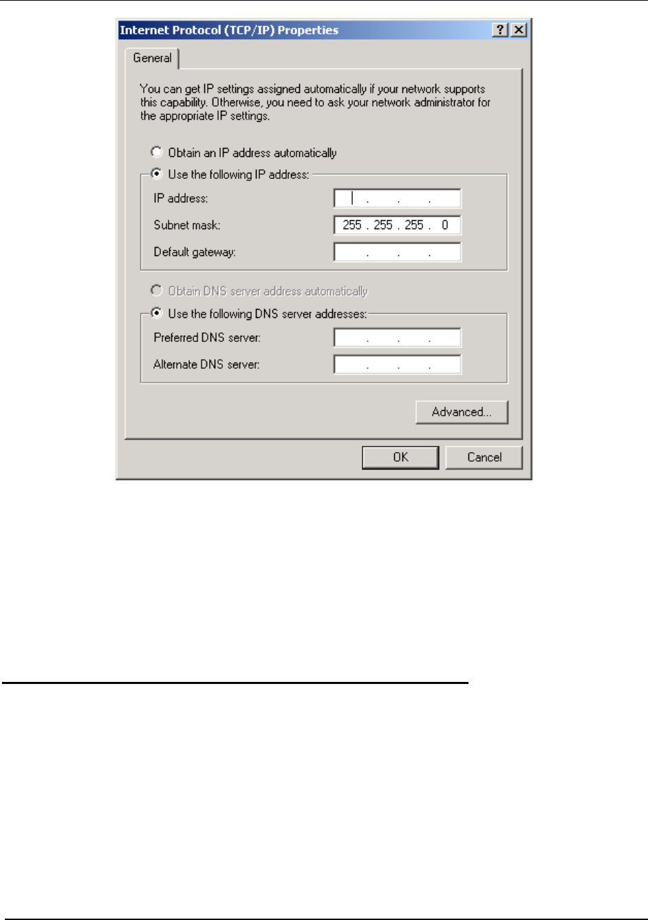
Setting the User Supplied IP Address
To setup the addressing for the User Supplied Scheme, first obtain a valid IP address from your
Network Administrator. This is the IP address to be entered in the IP Address box on the
Internet Protocol (TCP/IP) Properties dialog General tab.
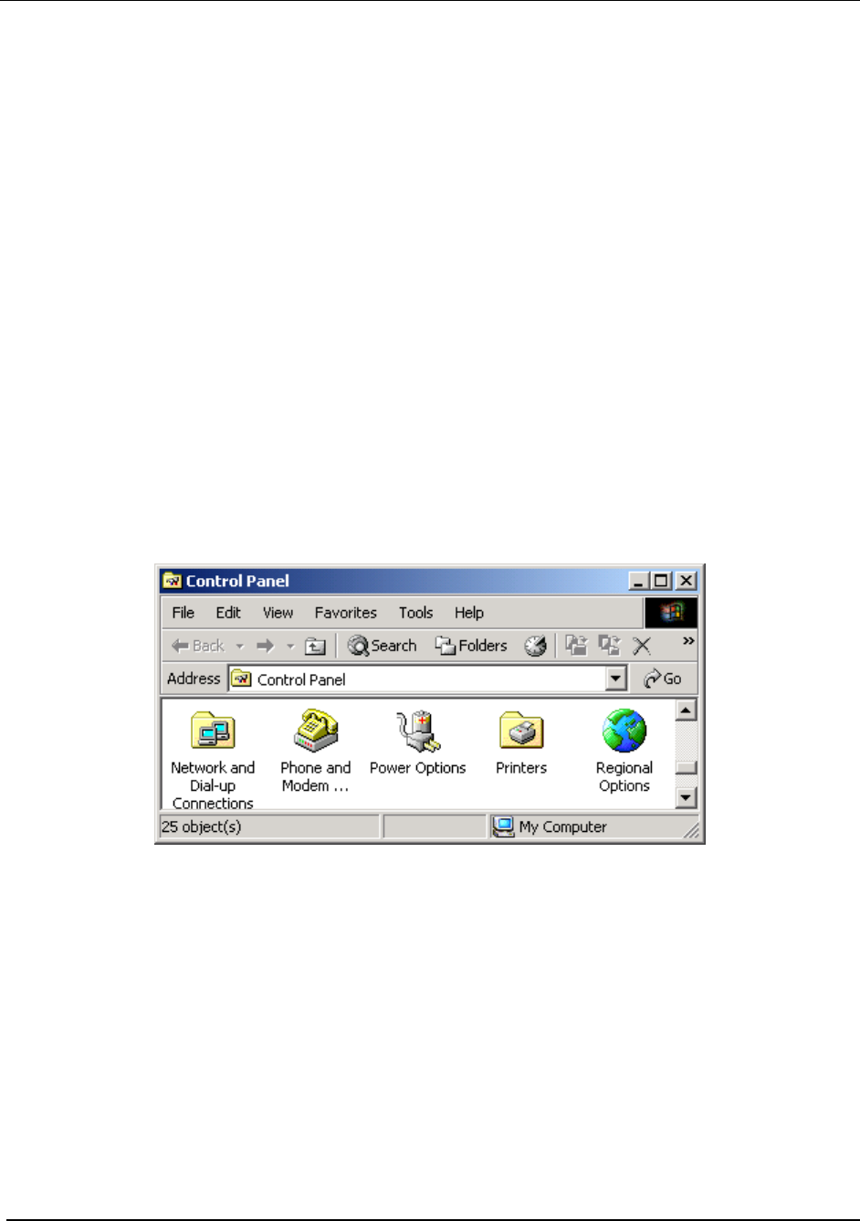
From the Start menu, select Settings Æ Control Panel. Double click on the Network and Dial-
up Connections icon.
Figure 4. Control Panel – Network and Dial-up Connections Icon
The Network and Dial-up Connections window will be displayed. Double click on the Local Area
Connection icon.
11
MeshNetworks
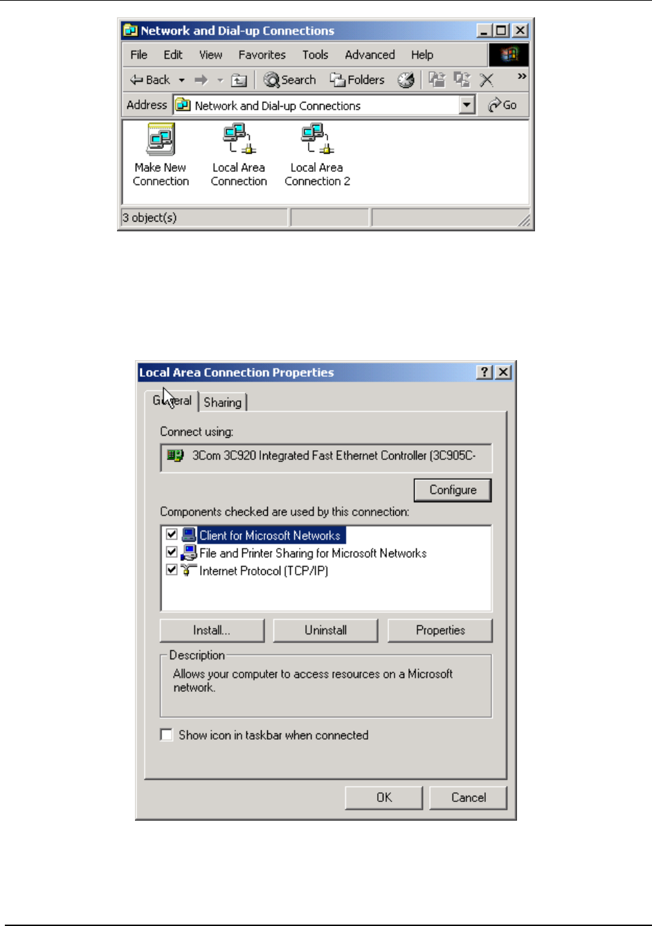
Figure 5. Network and Dial-up Connections Window
On the Local Area Connection Properties dialog, click to select Internet Protocol (TCP/IP) then
click on the Properties button.
Figure 6. Local Area Connection Properties Dialog Box
The Internet Protocol (TCP/IP) Properties dialog box will be displayed.
12
MEA Setup and Installation
Figure 7. Internet Protocol (TCP/IP) Properties Dialog Box
With the Use the following IP address: radio button selected, enter the IP address supplied by
the Network Administrator in the IP Address: box. Double click in the Subnet Mask: box to set
the default subnt mask. The Default gateway: and the DNS server addresses should have
already been set by the Network Administrator. Click on the OK button to accept the changes
and dismiss the dialog box.
Quality of Service (QoS) and User Priority Features
The MeshNetworks MEA system offers lower throughput than typical wired network systems.
As a result, it may be necessary to regulate traffic flows over the wireless portion of the network
so that interactive data flows and bulk data flows can be provided the proper levels of latency
and reliability. The required level of regulation is provided by the Quality of Service (QoS)
feature of the MEA system.
It may also be necessary to provide certain nodes higher priority access to the wireless network
for all of their traffic, such as in emergency or tiered service systems. This functionality is
provided by the User Priority feature.
Both QoS and User Priority deal with prioritization and shaping of packet traffic, are
incorporated into the MEA system design as a single design feature. QoS allows a traffic
generator to request special handling for enhanced throughput or reliability versus the standard
13

MeshNetworks
best effort traffic. User Priority allows a user to request that traffic to/from a node be given
preferential treatment. The resulting priority order is reflective of queuing order.
Quality of Service
The primary objective for QoS is to provide the capability of differentiating traffic classes. The
QoS provision will be implemented on a per-hop basis without explicit end-to-end QoS
management.
Three main QoS functionalities have been implemented:
1) Packet classification
2) Prioritized channel access
3) Priority queue management with rate limiting
User Priority
The User Priority service can be provisioned per-node for use with tiered service and
emergency access systems. This priority feature is unique to the MEA network and only exists
between endpoints within the MEA network or between a MEA network node and the
ingress/egress node on the MEA network.
Nodes outside of the MEA Core LAN cannot request a particular priority for transmitted or
received traffic. Any traffic into the MEA network needing prioritization must be prioritized at the
ingress access point or router. Any traffic out of the MEA network will lose its priority
assignment at the egress.
MEA wireless traffic will carry priorities attached to each packet. The MeshAPI can be used to
tune the default priority of the local node
There is also an optional Emergency mode for use by special applications. The priority for use
in emergency mode is separately provisioned and must be explicitly enabled per node by the
network operator.
14

MEA Setup and Installation
Section 3 - Setup and Installation
Subscriber Device (SD)
A Subscriber Device consists of both a Wireless Modem Card (WMC6300) and an End User
provided host device such as a notebook computer. The WMC6300 is designed for insertion
into an industry-standard Type II PCMCIA card slot located in a Host device. The WMC6300
has an antenna port to connect the external antenna and two LED Indicators. The Red LED is
the transmit indicator and the Green LED is the receive indicator as shown in Figure 8.
Equipment
The following list defines the MEA hardware components required to setup the WMC6300:
• WMC6300 Wireless Modem Card
• Antenna with a MMCX connector
• WMC6300 Software and Documentation CD for Windows 2000™ and Windows
XP™
Equipment that must be supplied by the End User includes the following:
• Notebook PCs running the Microsoft Windows 2000 (service pack 3) or Windows XP
(service pack 1) Operating System
Record MAC Address of the WMC6300
The transceiver MAC address is recorded on the back of the WMC6300 cards. Record this
number in Section 4 - MAC Address Tables, as it will be required later to configure and test the
device.
Figure 8. WMC6300 Antenna Port and LED Indicators
Loading and Verifying WMC6300 Software
The MEA WMC6300 Software and Documentation CD contains the MEA drivers and MeshTray
software for use on the End User’s equipment. Please review the instructions for each
1

MeshNetworks
operating system as there is a different sequence of events depending on the operating system.
Detailed instructions can be found in the WMC6300 User’s Guide for each operating system.
In addition, the MEA Administration Software and Documentation CD includes installation
software to load the MeshView Administration Tool. MeshView may be installed as an option on
a subscriber device to assist the Network Operator with network deployment. Refer to the MEA
MeshView Administration Tool User’s Guide for additional information on this application.
Installing the WMC6300 Software for Windows XP
The MEA WMC6300 Wireless Modem Card User’s Guide for Windows XP provides complete
step-by-step instructions for use during the installation and configuration of the WMC6300. The
following is an abbreviated version of the installation process.
Note: Please install the MEA Software after you insert the WMC6300 card. .
Complete the following procedure to install the WMC6300 software and drivers:
1.
2.
3.
4.
5.
6.
7.
8.
1.
2.
3.
Insert the antenna into the WMC6300 card.
Insert the WMC6300 card into the computer.
Click the Cancel button for the 2 Found New Hardware windows.
Insert the WMC6300 Software and Documentation CD into the computer’s CD-ROM
drive.
Start driver install by clicking on d:\software\meaclientinstall.exe (where “d” is the CD-
ROM drive)
The MEA Setup program will be displayed. Click the OK button.
Click the Next button to continue the software installation process.
Follow the onscreen prompts to complete the software installation process.
Installing the MeshView Administration Tool
Complete the following procedure to install MeshView:
Insert the MEA Administration Software and Documentation CD into the CD-ROM drive.
Click the Windows Start menu. Click on Run and enter d:setupmv.exe in the textbox
(Note: d is the letter of the CD-ROM drive). Click the OK button to continue the
installation process.
Follow onscreen prompts to complete the installation process.
DNS Server Configuration
The DNS server IP address is automatically supplied to the Subscriber Device upon
successfully connecting to the Network. If there are problems with resolving web URLs, the
DNS address can also be manually configured. The Network Operator must supply the DNS IP
address for the Internet connection.
Instructions to setup a Windows 2000 Host:
1. Start/Settings/Network and Dial-up Connections/Local Area Connection
(choose the Local Area Connection Corresponding to the Wireless Modem Card)
2. Click on the Properties button.
2

MEA Setup and Installation
3. Highlight Internet Protocol (TCP/IP) in the Components window.
4. Click on the Properties button.
5. Click on the Advanced button.
6. Click on the DNS tab
7. Click on the DNS Add button.
8. Enter the DNS Server IP Address provided by the network administrator and then click
the Add button.
9. Click the OK button to close the Advanced TCP/IP Settings windows.
10. Click the OK button to close the Internet Protocol (TCP/IP) Properties windows.
11. Click the OK button to close the Local Area Connection Properties windows.
12. Click the Close button to close the Local Area Connection Status window.
This configuration should remain in the Windows 2000 host.
Instructions to setup a Windows XP host:
1.
2.
3.
4.
5.
6.
7.
8.
9.
10.
11.
12.
13.
1.
Click on Start/Control Panel/Network and Dial-up Connections/Local Area Connection
Right click on the Local Area Connection Corresponding to the Wireless Modem Card
and select Properties from the pop up menu.
Highlight Internet Protocol (TCP/IP) in the Components window.
Click on the Properties button.
Click on the Advanced button.
Click on the DNS tab
Click on the DNS Add button.
Enter the DNS Server IP Address provided by the network administrator and then click
the Add button.
Click the OK button to close the Advanced TCP/IP Settings windows.
Click the OK button to close the Internet Protocol (TCP/IP) Properties windows.
Click the OK button to close the Local Area Connection Properties windows.
Click the Close button to close the Local Area Connection Status window.
This configuration should remain in the Windows XP host.
Installing the WMC6300 Software for Windows 2000
The MEA WMC6300 Wireless Modem Card User’s Guide for Windows 2000 provides complete
step-by-step instructions for use during the installation and configuration of the WMC6300. The
following is an abbreviated version of the installation process.
Note: Please install the MEA Software before you insert the WMC6300 card.
Complete the following procedure to install the WMC6300 software and drivers:
Insert the WMC6300 Software and Documentation CD into the computer’s CD-ROM
drive.
3

MeshNetworks
2.
3.
4.
5.
6.
7.
Start driver install by clicking on d:\software\meaclientinstall.exe (where “d” is the CD-
ROM drive)
The MEA Setup program will be displayed. Click the OK button.
Click the Next button to continue the software installation process.
Follow the onscreen prompts to complete the installation process.
Insert the antenna into the WMC6300 card.
Insert theWMC6300 card into the PCMCIA slot of the host computer.
If MeshView is desired, insert the MEA Administration Software and Documentation CD, open
the Windows Start menu, click on Run, and then type d:\software\meamvsetup.exe (where d
is the letter of the CD-ROM drive) and click the OK button. Follow onscreen prompts to
complete the installation process.
Testing
When the WMC6300 is inserted, you should receive an audible indicator that the device has
been recognized. (If there was a problem with the driver installation, Windows will prompt you
for a new device installation.)
Using MeshTray, select the Configuration tab, and then configure the WMC6300 address
scheme to be “User Supplied”.
Click on the Windows Start button and select Run from the popup menu. Enter the command
ipconfig in the textbox and click on the OK button to check your IP address. If an IP address in
the range of 10.x.y.2 is displayed, the transceiver is working properly. Using MeshTray, reset
the WMC6300 back to addressing scheme used to deploy the network.
Intelligent Access Point (IAP)
The IAP is an infrastructure device that is positioned at a fixed location such as a building
rooftop. The IAP6300 requires professional installation to ensure that the installation is
performed in accordance with FCC licensing regulations.
The principle function of the IAP is to provide the Subscriber Devices in the coverage area of
the IAP access to wired services. The IAP also provides a fixed location reference for Geo-
Location, provides wireless routing for units in the IAPs coverage area, and is the principal
network management interface to associated Wireless Routers and Subscriber Devices.
The MEA IAP provides a mounting bracket designed to be attached to a pole. For a MEA
deployment, a permanent power source for each IAP must be provided. The standard IAP
requires AC power, however there is an optional configuration for DC power. The RJ-45
weatherproof plug can be terminated in the field, allowing custom lengths to be assembled
quickly on site.
Equipment
The following list defines the standard MEA hardware components for the IAP:
• IAP Box with N-type Female Antenna Connector
• 120V A/C Power Cable with a NEMA 5-15 plug
• Antenna with N-type Male Antenna Connector
4

MEA Setup and Installation
• Weatherproof RJ-45 Connector
• Mounting Bracket
The Network Operator must supply the following:
• Mounting Location
• Power Source (120V A/C or 5V D/C, depending on IAP configuration)
• Ethernet connection between the IAP and the MiSC
• Hand tools for bracket installation (7/16 wrench (2), Phillips screwdriver)
Optional Equipment:
• DC powered IAP (IAP6300-DC-IN)
• Power cord to connect to a photoelectric cell
Optional FCC Approved Antennas:
Manufacturer Part Number Gain Usage
Maxrad MFB24008 8 dBi Infrastructure
Maxrad MFB24004 4 dBi Infrastructure
Hyperlink HG2409U 8 dBi Infrastructure
Centurion WCR2400MMCX 2 dBi Laptop/PDA
Centurion WCR2400MMCX12 1 dBi Laptop/PDA
Maxrad BMMG2400ML195MSMA 0 dBi Mobile
Antenex TRA24003 3 dBi Mobile
5
MeshNetworks
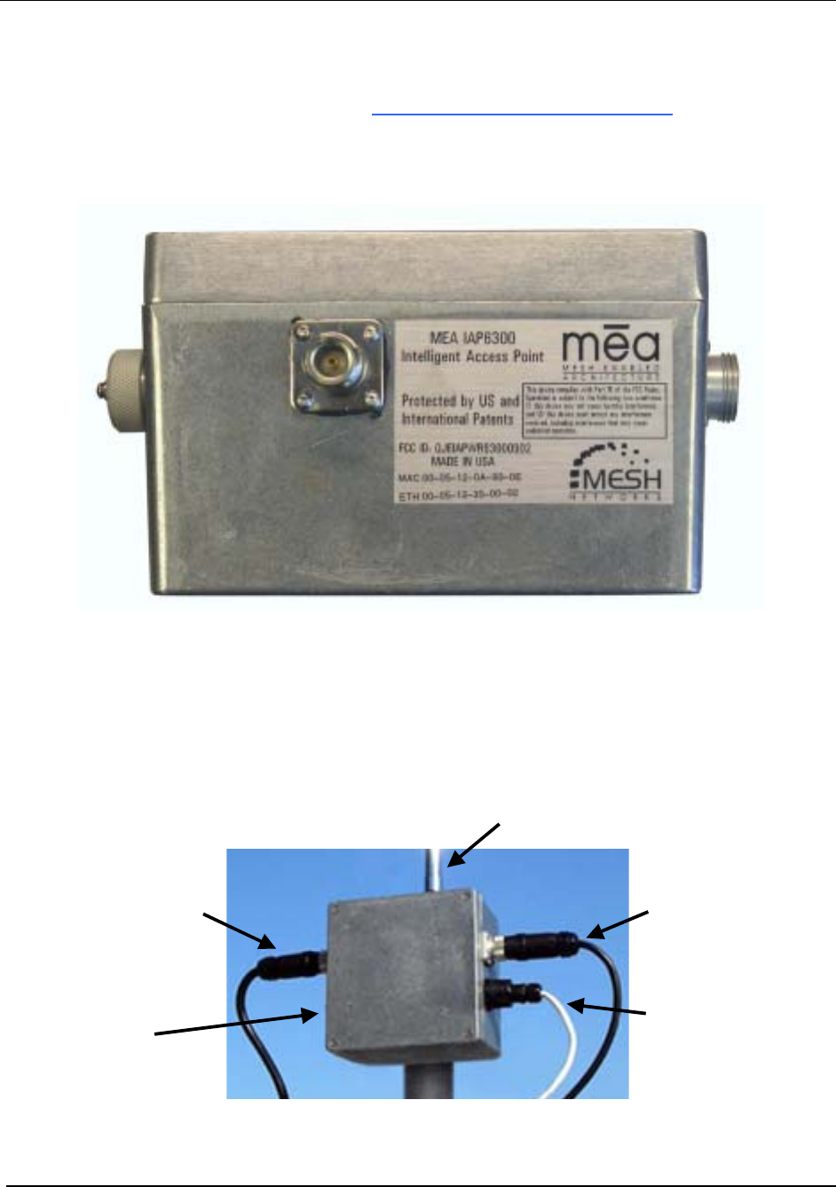
Record MAC Address of the IAP
The transceiver MAC address is recorded on a label located on the antenna end of the IAP as
shown in Figure 9. Record this number in Section 4 - MAC Address Tables, because it will be
required later to configure and test the device. Both SBC ETH and XCVR MAC addresses
should be recorded.
Figure 9 IAP6300 Identification Label
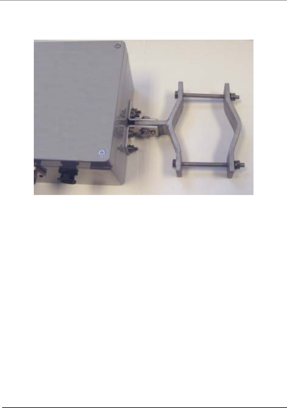
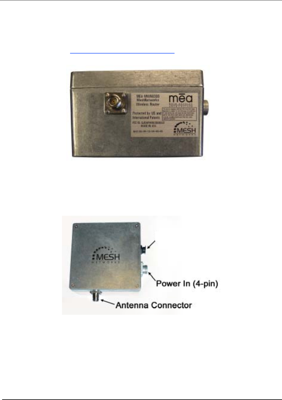
IAP Assembly
The Figure 10 shows the external connection points on an IAP6300 box. Figure 11 show the
mounting bracket.
A
ntenna Connecto
r
Power Out (3-pin)
(
o
p
tional
)
Power In (4-pin)
Test Port
(Not Shown)
RJ45 (Data) Port
Figure 10. IAP6300 Connection Points
6
MEA Setup and Installation
Figure 11. IAP6300 Bracket
7
MeshNetworks
Assemble the IAP using the following procedure:
1.
2.
3.
4.
5.
6.
If desired, mount the IAP6300 box using the enclosed bracket. Refer to Figure 11.
Place the bracket at the desired position on the pole The bracket can accommodate
pole diameters between 1-3.5 inches.
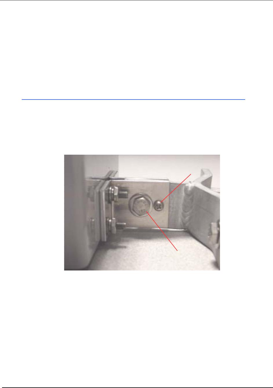
Adjust the position of the box so that the antenna will be in a vertical position. Tighten
the pivot and angle locking bolts on the shaft of the bracket as shown in Figure 12
Insert the antenna into the N-type Connector on the top of the box, and rotate to close.
Insert the IAP Power Plug into the 4-pin connector.
Install the weatherproof connector on the Ethernet cable as described at:
http://www.siemon.com/installation_instructions/pdf/IMAXIndustrialUTPPlug.pdf
7.
8.
9.
Insert the Ethernet Cable into the RJ-45 port and tighten the connector to ensure a
weatherproof seal.
If used, insert the Media Converter Power Cable into the optional 3-pin connector.
The Test Port is unused during deployment
6 x 32 x 3/4
Angle Locking Bolt
1/4 x 1 inch Pivot Bolt
(Requres 7/16 Wrench)
Figure 12. Bracket Adjustment Bolts
Deployment
The IAP may be mounted on a pole having a diameter of 1-3.5 inches, utilizing the provided
bracket. The antenna must have a separation distance of at least 2 meters from the body of all
persons and must not be co-located or operating in conjunction with any other antenna or
transmitter. Users and installers must be provided with antenna installation and transmitter
operating conditions to satisfy RF exposure compliance.
When deploying the IAP, the antenna should be a minimum of 30 inches from any nearby metal
poles to avoid distortion of the RF pattern.
The IAP must have an Ethernet connection to the MiSC. If the distance between the IAP and
8

MEA Setup and Installation
the MiSC is greater than 100 meters, the Network Operator may utilize a T1 with the optional
Net-to-Net boxes. The IAP optionally has a 5V, 3-pin, power out connection on the side of the
box to power the Net-to-Net boxes. Other media converters may be used at the network
operator’s discretion.
The installation location must provide power to the IAP.
It is the responsibility of the Network Operator to ensure that the installation complies with any
local building codes and permits.
Initial IAP Configuration
Prior to attempting configuration of the IAP, the IAP must be powered on and have connectivity
to the MiSC.
Geo-location is an configuration item that is entered into an infrastructure device via the Device
Manager tool, located on the MeshManager server (refer to the MeshManager User’s Guide).
MeshNetworks recommends that a DGPS receiver be used to obtain accurate GPS
coordinates, and that the longitude, latitude, and altitude values have a precision of 5 digits
following the decimal point.
Testing
Once there is an Ethernet connection to the MiSC, verify the health of the IAP with the following
procedure:
1.
2.
Apply power to the IAP.
Obtain the transceiver and SBC MAC addresses that were recorded in Section 4 - MAC
Address Tables. The address will be in the format 00-05-12-0A-xx-yy.
3.
4.
From MeshManager, display devices using the MAC address.
Select the appropriate IAP in the device tree, and then ping the device (right click and
select ping).
A response to the ping commands verifies that both the transceiver and SBC are
communicating.
9

MeshNetworks
Wireless Router (WR)
The MWR6300 (Wireless Router) is an infrastructure device positioned in a fixed location, such
as on a pole, wall, or rooftop. The MWR6300 requires professional installation to ensure the
installation is performed in accordance with FCC licensing regulations.
The Wireless Routers provides range extension, a means to route around obstructions, and a
fixed location reference for use in Geo-Location.
The MEA MWR6300s comes with a mounting bracket that can be attached to a pole with a
diameter of 1-3.5 inches. For a MEA deployment, a power source for each WR must be
provided.
Equipment
The following list defines the standard MEA hardware components needed to setup a WR:
• WR Box with N-type Antenna Connector
• 120V A/C Power Cable with a NEMA 5-15 plug
• Antenna with N-type Male Antenna Connector
• Mounting Bracket
The Network Operator must supply the following:
• Mounting Location
• Power Source (120V A/C or 5 V D/C depending on WR configuration)
• Hand tools for bracket installation (7/16 wrench (2), Phillips screwdriver)
Optional Equipment:
• DC powered WR (MWR6300-DC-IN)
• Power cord to connect to a photoelectric cell
Optional FCC Approved Antennas:
Manufacturer Part Number Gain Type
Maxrad Z1578 8 dBi Omni
Maxrad Z1576 4 dBi Omni
Hyperlink HG2409U 8 dBi Omni
Maxrad BMMG2400ML195MS 0 dBi Mobile
Antenex TRA24003 3 dBi Mobile
10
MEA Setup and Installation
Record MAC Address of the MWR6300
The transceiver MAC address is recorded on the label located on the antenna end of the
MWR6300 as shown in Figure 13.
Record this number in Section 4 - MAC Address Tables, because it will be required later to
configure and test the device.
Figure 13. MWR6300 Identification Label
MWR6300 Assembly
Figure 14 shows the external; connection points on a MWR6300 box.
Test Port
Figure 14. MWR6300 External Connection Points
Assemble the WR using the following procedure:
1.
2.
3.
If desired, mount the WR box using the enclosed bracket. Refer to the procedure in the
IAP assembly section of this document.
Insert the Antenna into the N-type Connector on the top of the box, and rotate to close.
Insert the Power Plug into the 4-pin Connector.
11

MeshNetworks
Verify the MAC address has been recorded in Section 4 - MAC Address Tables, as it
will be required to configure and test the device.
4.
5. The Test Port is unused during deployment.
Deployment
The MWR6300 can be mounted on a pole by using the provided bracket.
When deploying the MWR6300, the antenna should be a minimum of 30 inches from any
nearby metal poles to avoid distortion of the RF pattern. The antenna must have a separation
distance of at least 2 meters from the body of all persons and must not be co-located or
operating in conjunction with any other antenna or transmitter. Users and installers must be
provided with antenna installation and transmitter operating conditions to satisfy RF exposure
compliance.
Typically, wireless routers are distributed within a network to extend range and guarantee
coverage. A rule of thumb is to deploy 3-4 hop networks to optimize range, latency, and
throughput.
The MWR6300 installation location must provide applicable AC or DC power for the device.
It is the responsibility of the Network Operator to ensure that the installation complies with any
local building codes and permits.
Initial Configuration
The configuration process for Geo-Location is the same as the IAP.
Testing
Verify the operation of the MWR6300 using the following procedure:
1. Apply power to the MWR6300.
2. Obtain the transceiver MAC address that was recorded in Section 4 - MAC Address
Tables. The address will be in the format 00-05-12-0A-xx-yy.
3. From MeshManager, display devices using the MAC address.
4. Select the appropriate WR in the device tree, and then ping the device (right click and
select ping).
A response to the ping command verifies that the transceiver is communicating.
Mobile Internet Switching Controller (MiSC)
The MiSC provides routing, switching, and management functions for the wireless network, and
the connection to the wired world.
Equipment
The following list defines the standard MEA components needed for the MiSC:
• SMC 24 Port Switch
• Cisco 1721 – Edge Router
• Cisco 1721 – Core Router
12

MEA Setup and Installation
• MeshManager Server (Server, Monitor, Keyboard, Mouse), pre-installed with the
MeshManager software
• 5 Ethernet Cables
The Network Operator must supply the following:
• Physical location and AC power for the routers, switch, and server(s)
• Ethernet connection(s) from the switch to the IAP(s)
• Ethernet connection to Internet or to Network Operator’s private network (Custom IP
network configuration may be required depending on Network Operator’s network
configuration)
• Public address for Edge Router, DNS resolver address
• PC running Windows 2000 with an Ethernet Port for site-specific MiSC Configuration
and MeshView
• Optional Equipment:
• Geo Server
• T1 Network Extenders
13
MeshNetworks
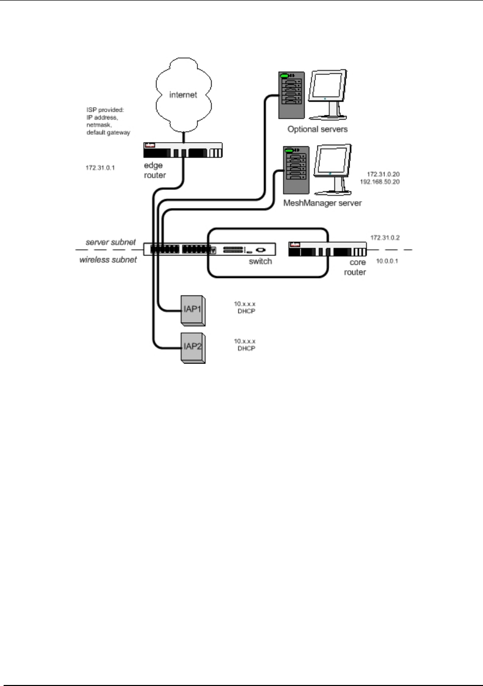
Network Setup Description
The basic MiSC hardware configuration is shown in Figure 15.
Figure 15. Basic MiSC Configuration
The following describes the parameters for setting up the network:
• All MEA wireless devices must be within the same subnet.
• MEA currently uses the non-routable 10.x.x.x (8 bit) subnet as defined in RFC 1918.
• The IAPs, WRs, and SDs will use DHCP to obtain an IP address, the default
configuration returns a 10.x.x.x address.
Subnet information may be modified by editing the DHCP configuration file (dhcpd.conf) located
on the MeshManager Server.
14

MEA Setup and Installation
MiSC Assembly
The MiSC hardware consists of commercial off-the-shelf components. The components are
pre-configured with a basic configuration that requires minimal site-specific changes.
The SMC switch arrives configured as two virtual LANs. The upper row of Ethernet ports is for
the server subnet; the lower row of ports is for the wireless subnet.
Unpack the SMC switch and mount as desired (either in a rack or on a table top). Connect the
switch to a power source.
Unpack the Cisco router labeled EdgeRTR and connect to a power source. Plug interface
labeled 10BT Ethernet into the Internet or the Network Operator’s private network. (The
network operator supplies this cable; it will be an Ethernet cable for connecting to a hub or
switch, or an Ethernet crossover cable if connecting to another router.) Plug interface labeled
10/100 Ethernet into the SMC switch on port 1.
Unpack the Cisco router labeled CoreRTR and connect to a power source. Plug interface
labeled 10BT Ethernet into the SMC switch on port 12. Plug the interface labeled 10/100
Ethernet into the SMC switch on port 24.
Unpack the Sun Blade/MeshManager server and monitor and connect to a power source. Plug
the network interface into any of the ports 2-11 on the SMC Switch.
Connect Network Operator supplied computer running Windows 2000. Plug the network
interface into any of the ports 2-11 on the SMC Switch.
Connect the IAPs to any of the ports 13-23 on the SMC switch.
Upgrade MiSC/DHCP Configuration (optional)
Mea Version 1.x required the wireless subnet to be configured as 10.x.x.x. mea Version 2 continues to
use the 10.x.x.x addressing scheme as a default; however it can be changed to a site specific address.
The following procedure describes the changes necessary to accomplish this.
The following items must be configured to change the MEA wireless subnet. (Refer to Error!
Reference source not found.)
Edge router
• IP route to the wireless subnet via the core router (default 10.0.0.1)
• NAT access list for wireless subnet
Core router
• IP address of the wireless network interface (default 10.0.0.1)
Sun server
• DHCP dhcpd.conf, for the new pool of addresses, new default router, new broadcast
address
• DNS named.conf and zones file, for the new subnet range
The SMC switch does not require any changes, since the partitioning of the switch does not
involve IP addresses.
When the mea Version 2 upgrade of the IAPs is complete, the IAPs, WRs, and SDs should all
15
MeshNetworks
be handled automatically by the DHCP changes. These should refresh automatically when the
DHCP lease time expires (600 seconds) and they refresh their DHCP lease. This can be
hurried by simply resetting the devices once the other changes have been completed.
Changing the Wireless Subnet
The IP address of the default gateway used by any MEA device must not be within the either of
the wireless subnets configured in all IAPs. Otherwise, SD hosts will be unable to resolve the
IP address of the default gateway. There are two wireless subnets configured for IAPs in
MeshManager on the IAP device configuration window, the local wireless subnet, fields Local
Wireless Subnet and Local Wireless Subnet CIDR (defaults are 10.2.0.0 and 16), and the
global wireless subnet, fields Global Wireless Subnet and Global Wireless Subnet CIDR
(defaults are 172.16.1.50 and 24).
If wired devices will be connected to the MEA subnet, all IAPs must be configured with the
address range of the wired devices if MEA devices need to communicate with them.
Otherwise, SD hosts will be unable to resolve IP addresses of wired devices within the same
subnet. The wired device address range is configured for IAPs in MeshManager on the IAP
device configuration window, fields Global Wireless Subnet and Global Wireless Subnet CIDR
(defaults are 172.16.1.50 and 24).
Figure 16 MEA Subnet Data
16

MEA Setup and Installation
Onsite Configuration of Routers
EdgeRTR Configuration
The EdgeRTR must have on-site configuration done if there is a desire to connect to the
Internet. Prior to performing the following steps, obtain the IP address, netmask, and default
gateway for the public interface from the Internet Service Provider. These are shown as
ip.ip.ip.ip, nm.nm.nm.nm, and gw.gw.gw.gw, respectively, in the instructions below. Also,
obtain the IP address of the EdgeRTR, it will be in the form of 172.31.0.1.
Telnet into the EdgeRTR from a computer connected to the server subnet. Use the address
172.31.0.1 to connect to the EdgeRTR.
Update the public IP information using the commands below
Password:g0ld1
EdgeRTR>enable
Password:g0ld11
EdgeRTR#configure terminal
Enter configuration commands, one per line. End with CNTL/Z.
EdgeRTR(config)#interface Ethernet0
EdgeRTR(config-if)#ip address
ip.ip.ip.ip
mm.nm.nm.nm
EdgeRTR(config-if)#exit
EdgeRTR(config)#no ip route 0.0.0.0 0.0.0.0
EdgeRTR(config)#ip route 0.0.0.0 0.0.0.0
gw.gw.gw.gw
EdgeRTR(config)#exit
EdgeRTR#copy running-config startup-config
Destination filename [startup-config]? <return>
Building configuration...
!!!!!!!!!!!!!!!!!!!!!!!!!!!!!!!!!!!!!!!!!!!!!!!!!!!!!!!!!!!!!!!!!!!!!!!!!!!![OK]
EdgeRTR#exit
EdgeRTR TEST
Use a computer connected to the switch (in either the server or wireless subnet) to ping to the
ISP gateway IP. Next, test access to the Internet using a web browser. If this fails troubleshoot
and retry.
17
MeshNetworks
Network Configuration – Device Manager
Device Manager is a utility located on the MeshManager server. It is used to configure and
monitor the deployed network. Refer to the MeshManager User’s Guide for detailed instructions
on how to use the Device Manager.
MEA systems are delivered with the initial configuration of IAPs, WRs, and SDs in the
MeshManager system. This allows for easy testing of the system as units are tested on site.
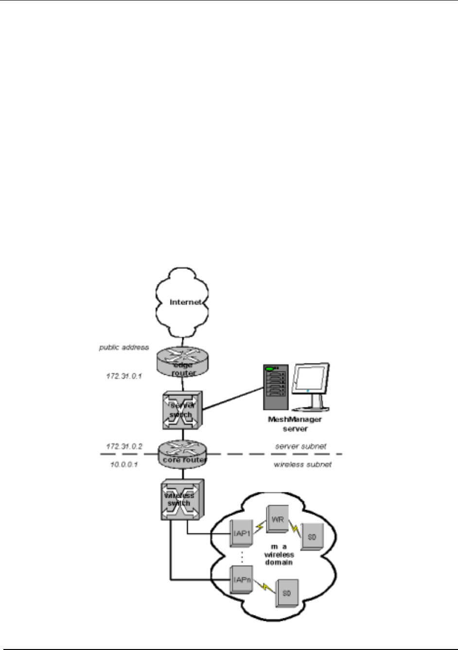
Network Configuration – IAP Configuration Via Web Interface
A second method of performing various network configuration functions for an IAP may be
accomplished using a standard web browser. Connect a host PC to the switch in the MiSC.
Using a standard Internet Browser such as Microsoft’s Internet Explorer or Netscape, enter the
IP Address corresponding to the IAP’s SBC MAC to be configured as shown in Figure 17. It
is recommended that you install and configure the IAPs one at a time.
Figure 17. MEA Device Administration Connection
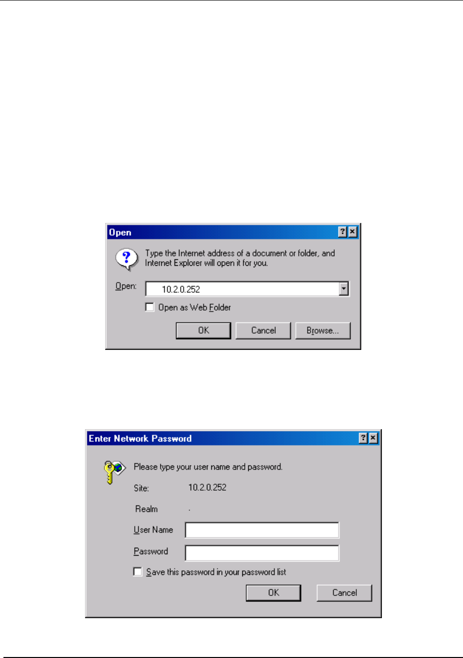
A Log On window for the Administration Utility will be displayed in the browser, as shown in
Figure 18. Before the Administration Utility is displayed, the user must complete the simple
logon procedure before proceeding. The default login is admin and the password is admin.
The password can be changed, as described further in this document.
Figure 18. MEA Device Administration Logon Window
18

MeshNetworks
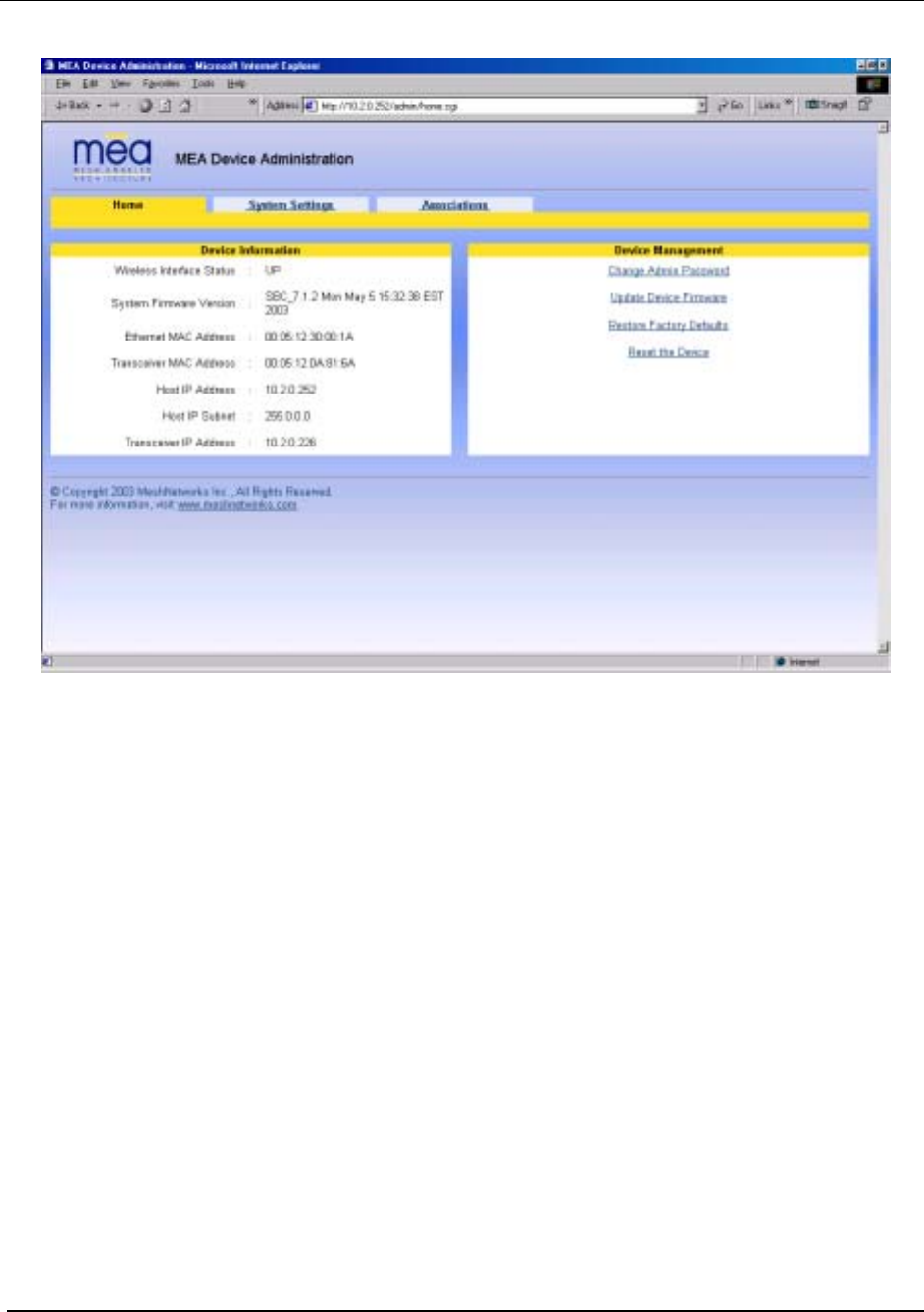
Home Tab
Figure 20. MEA Device Administration Home Tab
The Device Information window provides data on:
• Wireless Interface Status (interface between the Host and the transceiver)
• System Firmware Version (software running on the Host in the IAP)
• Ethernet MAC Address (MAC address of the Host)
• Wireless MAC Address (MAC address of the transceiver)
• Host IP Address (the DHCP provided address for the Host)
• Transceiver IP Address (the DHCP provided address for the transceiver)
Also located on the Home Tab are Device Management options for
• Change Administration Password
• Update Device Firmware
• Restore Factory Defaults
• Reset the Device
The Device Management options are detailed below.
20
MEA Setup and Installation
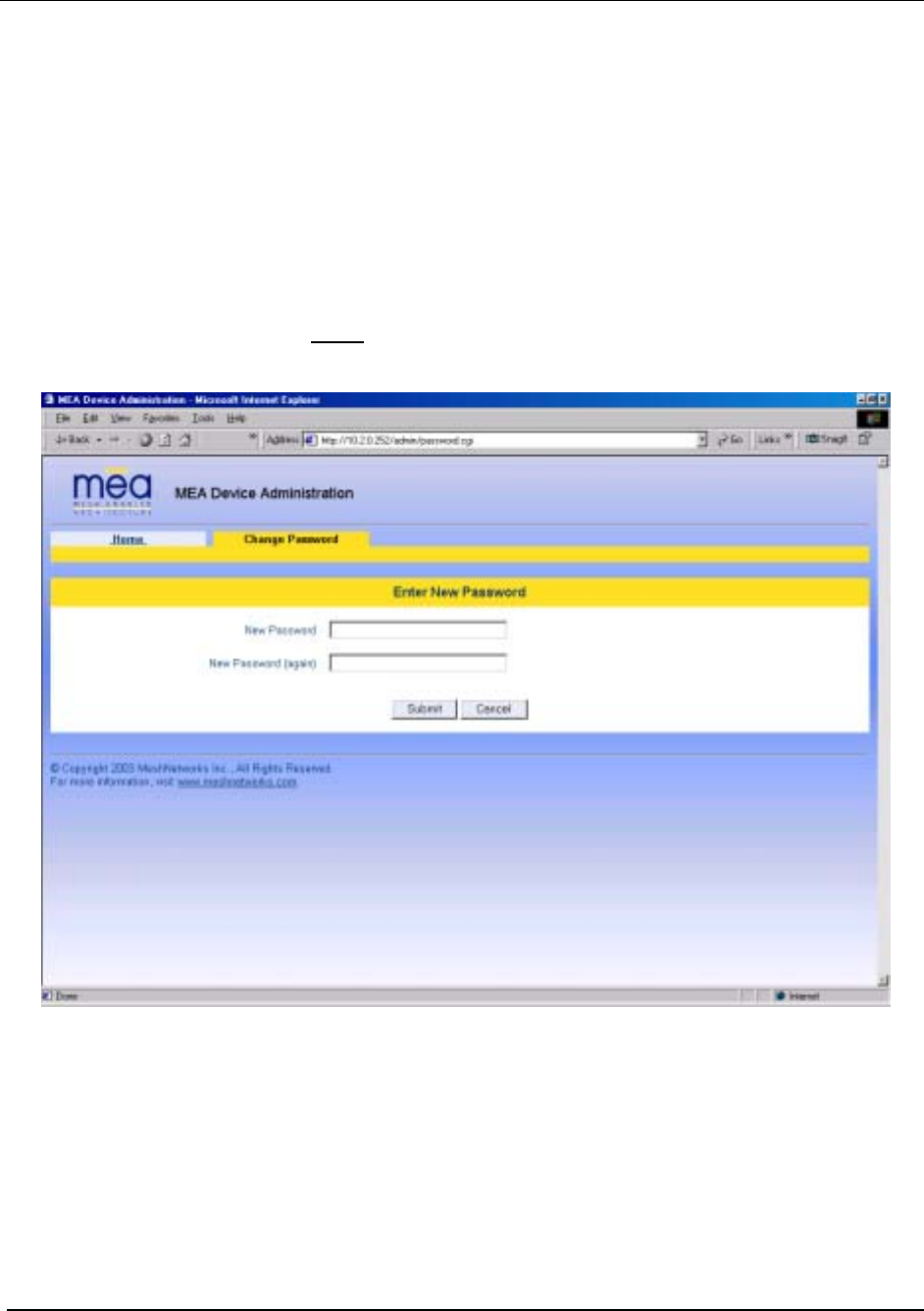
Home Tab – Change Admin Password
From the Home tab, the user can select the Change Admin Password to change the
administrator password of the device.
WARNING – If the password is lost, the password can only be reset at the factory. Do not
forget to record the information in an appropriate location for future use.
To change the password, select Change Admin Password. 1.
2.
3.
Enter the new password will be displayed on the Change Password window as shown in
Figure 21. Enter the new password in the New Password textbox.
Enter the new password again in the New Password (again) textbox.
Figure 21. MEA Device Administration Enter New Password Window
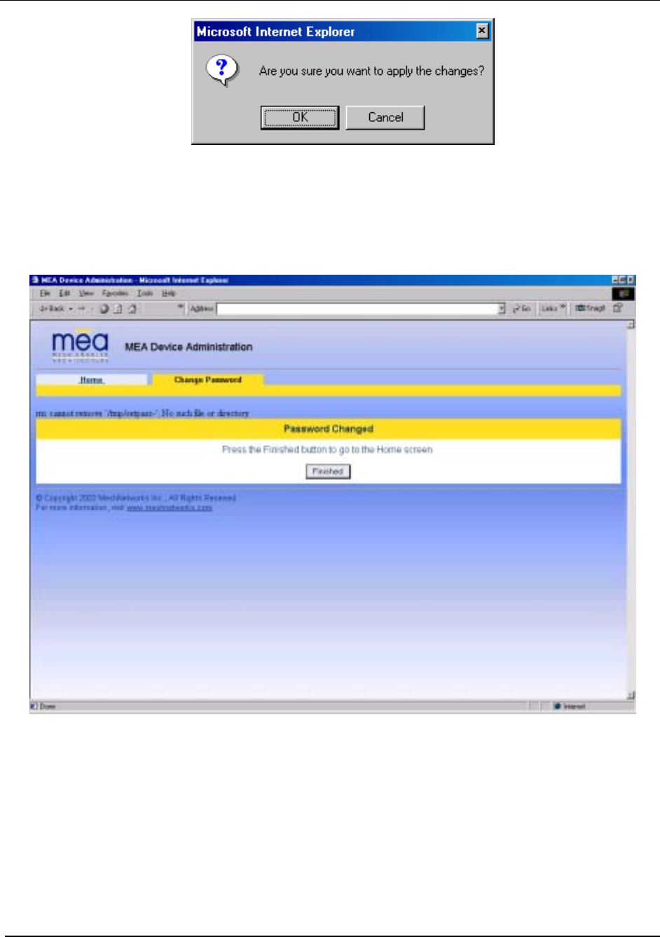
Click on the Submit button. A confirmation window will appear as shown in Figure 22.
Click on the OK button to continue.
4.
21
MeshNetworks
Figure 22. MEA Device Administration Confirmation Window
5. The browser will display a message that confirms the password change as shown in
Figure 23. Click on the Finished button to continue.
Figure 23. MEA Device Administration Password Changed Window
6. A Logon window will now prompt for the new password.
22
MEA Setup and Installation
Figure 24. MEA Device Administration Logon Window
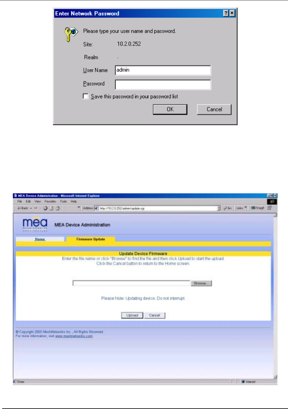
Home Tab – Update Device Firmware
From the Home Tab, select Update Device Firmware to load a new version of the firmware into
the IAP.
. A New Device Firmware window will be displayed as shown in Figure 25
Figure 25. MEA Device Administration Update Device Firmware Window
23
MeshNetworks
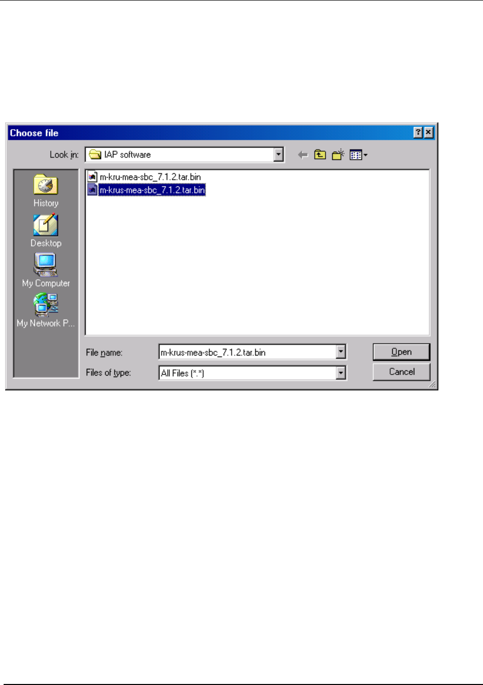
Specify the path and file name of the firmware bin file to be uploaded to the device. Or
click on the Browse button to navigate to the correct location of the firmware bin file. If
the Browse button is selected, the Choose file window is displayed as shown in Figure
26. Locate and select the desired firmware bin file to be uploaded to the device. Then
click on the OK button.
1.
Figure 26. MEA Device Administration Choose File Window
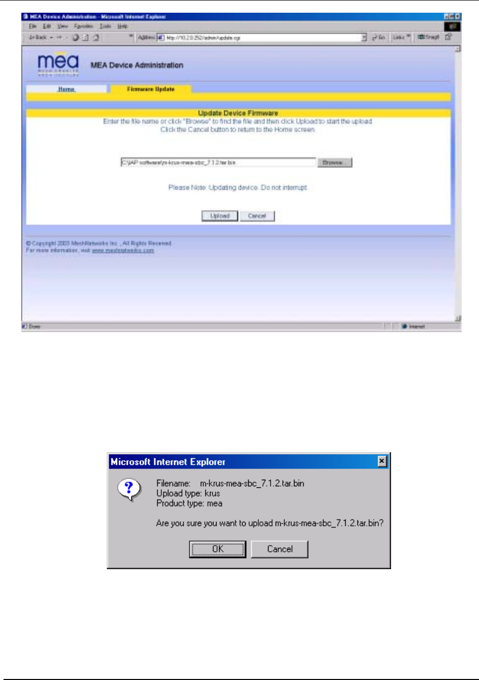
The path and file name of the firmware bin file will be displayed in the Update Device
Firmware window as shown in Figure 27. Click on the Upload button to continue the
process or select Cancel to terminate the Firmware Update procedure
24
MEA Setup and Installation
Figure 27. MEA Device Administration Update Device Firmware Window (2)
2. If the Upload button is selected, an upload confirmation message is displayed as shown
in Figure 28 to confirm that you want to continue the Firmware Update procedure. Click
on the OK button to continue or select Cancel to terminate the Firmware Update
procedure.
Figure 28. MEA Device Administration Update Confirmation Window
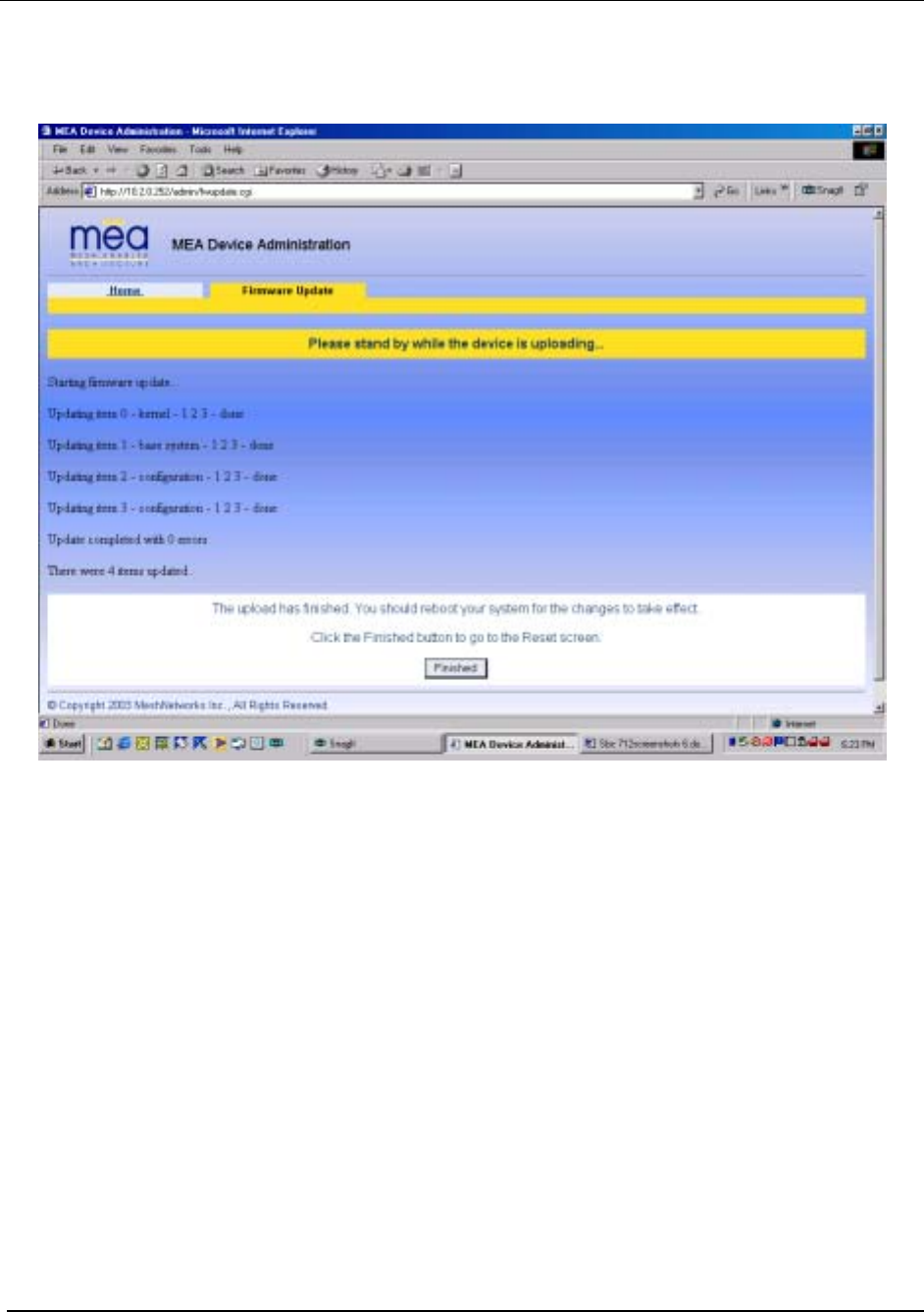
3. If the OK button is selected, the new Firmware is loaded into the device. The Firmware
Update window will then be displayed to indicate that the selected file was successfully
uploaded and to recommend that you reboot the device.
25
MeshNetworks
As the Firmware is being uploaded, a status page is displayed as shown in Figure
29.
4.
5.
Figure 29. MEA Device Administration Update Device Status Window
At the completion of the update, the IAP’s SBC must be reset for the update to take
effect. Select the Finished button to navigate to the Reset Device window, and then
click on the Reset button as described in the procedure located on page 30. The device
will reset and return to the Home tab.
Note: Do not close the browser until the process is complete.
Home Tab – Restore Factory Defaults
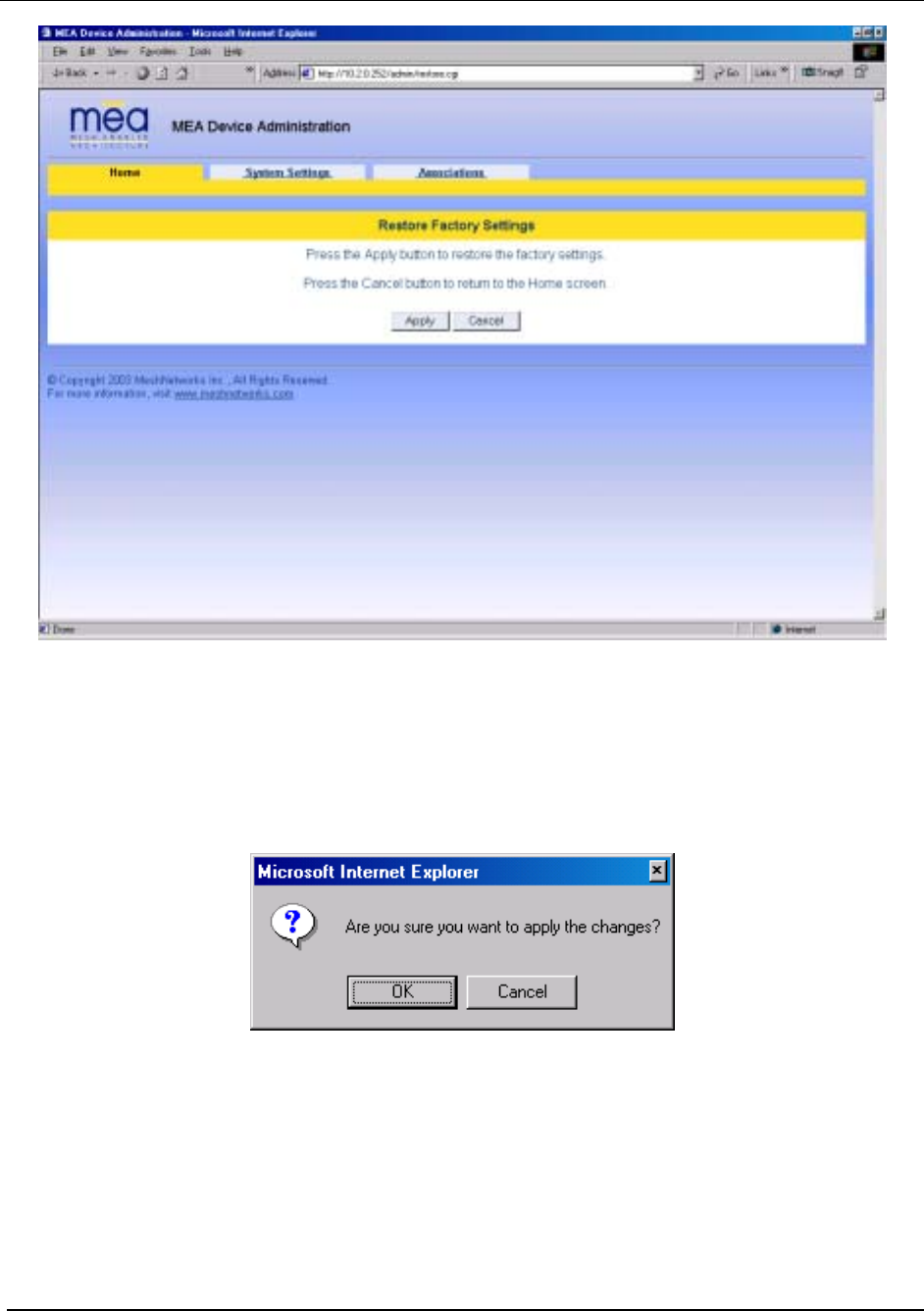
From the Home Tab, the user can select Restore Factory Defaults to restore the configuration
settings to Factory Default settings. By selecting the Restore Factory Defaults button, the IAP
setting will be returned to the default configuration. The user will receive a caution message
before proceeding with the restore process as shown in Figure 30.
26
MEA Setup and Installation
Figure 30. MEA Device Administration Restore Factory Defaults Window
6.
7.
Click on the Apply button to continue the restore process or select the Cancel button to
terminate the process with out changing the device settings.
If the Apply button is selected, a confirmation message is displayed as shown in Figure
31 to confirm that you want to continue the Restore Factory Settings procedure.
Figure 31. Restore Factory Defaults Confirmation Message
Click on the OK button to continue or select Cancel to terminate the procedure. 8.
27

MeshNetworks
Figure 32. MEA Device Administration Factory Settings Restored Window
28
MEA Setup and Installation
Figure 33 MEA Device Administration Device Reset Window
If the OK button is selected, the configuration settings will be restored and the device will reset
automatically. Upon completion of the process, the browser will return automatically to the
Home tab.
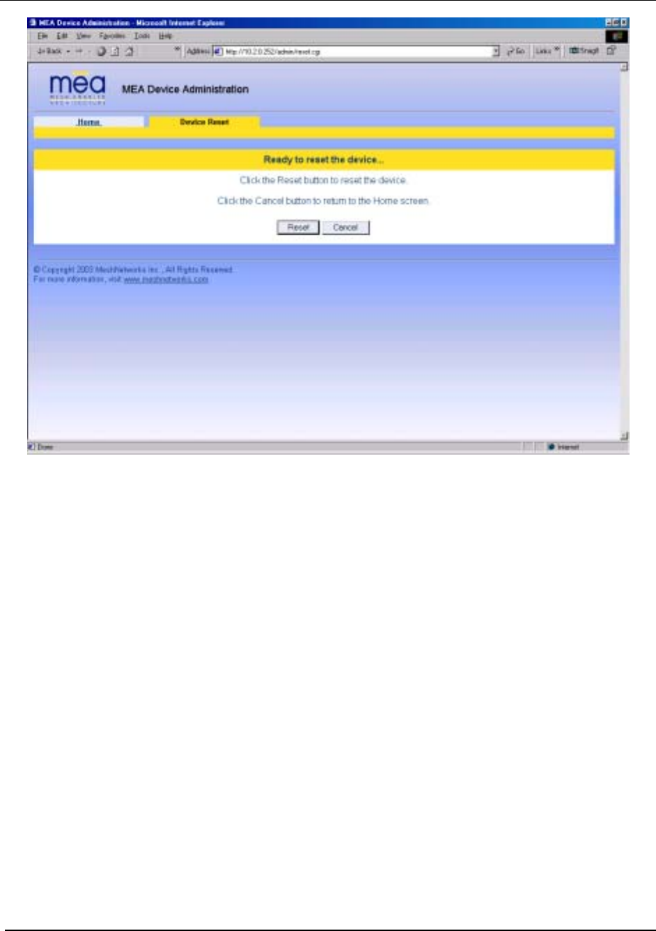
Home Tab – Reset Device
From the Home tab, the user can select the Reset the Device option to reset the device and
reinitialize the IAP. The configuration settings are preserved during the initialization process.
The user will receive a caution message before proceeding with the reset.
Select the Reset the Device button to initiate the reset process on the IAP. 1.
2. The Reset the Device window is displayed as shown in Figure 34. Select the Reset
button to continue the process.
29
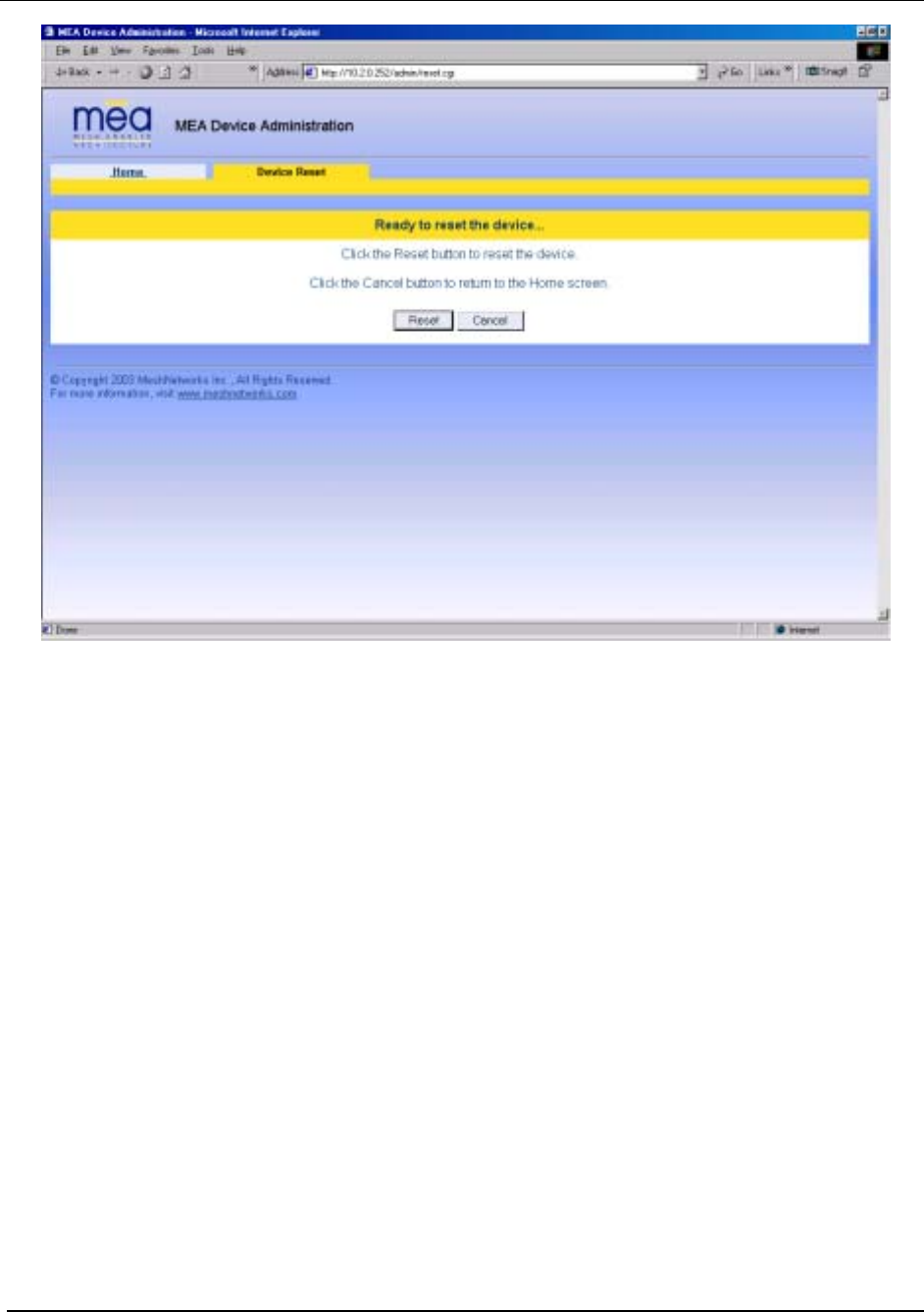

MEA Setup and Installation
Figure 35. MEA Device Administration Device Reset Window (2)
31
MeshNetworks
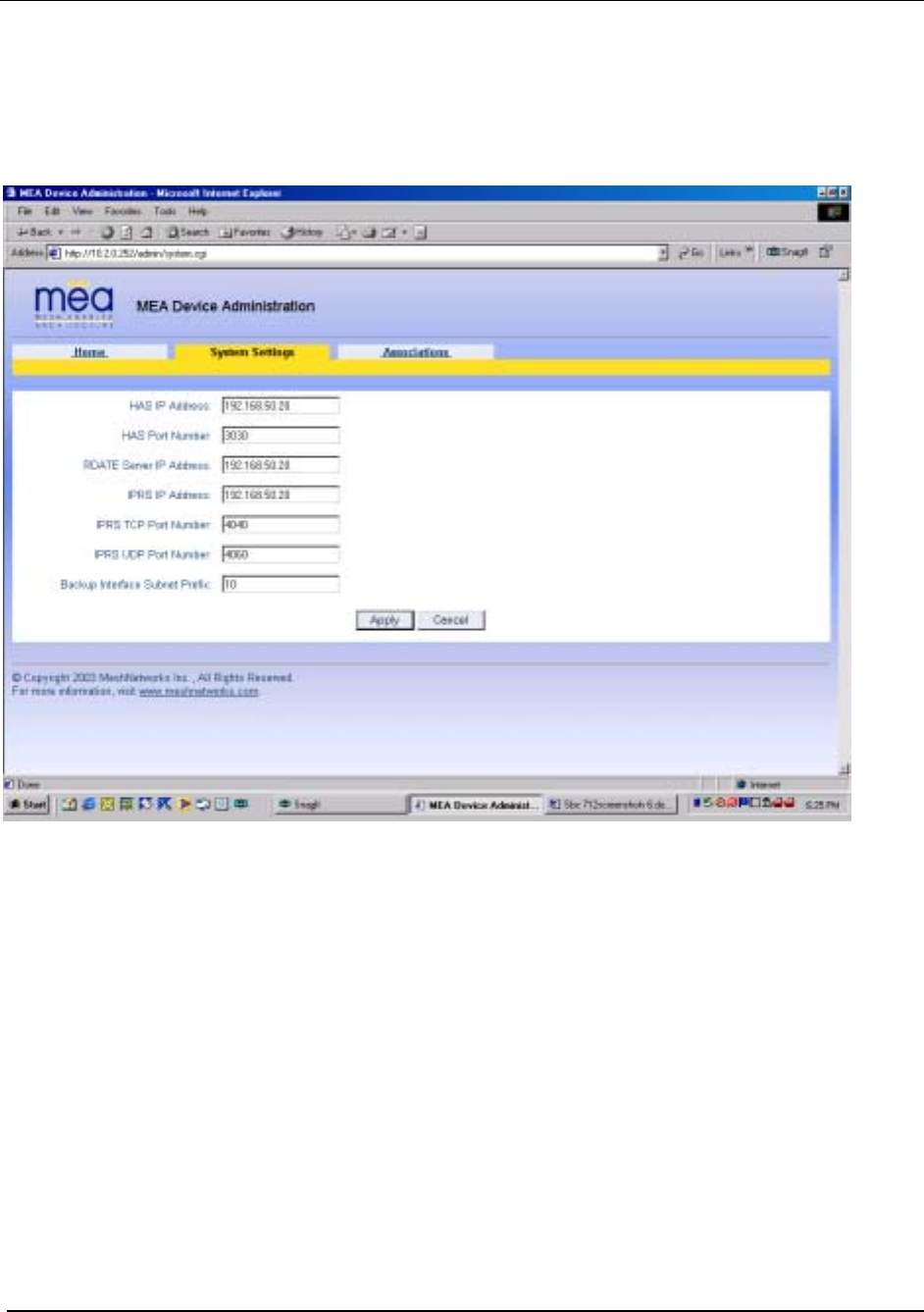
System Settings Tab
The System Settings Tab is shown in Figure 36.
Figure 36. MEA Device Administration System Settings Tab
The System Settings tab allows the network operator to change the following values:
HAS IP Address – (Hardware Authentication Server) Network host from which authentication is
requested.
HAS Port Number – Port number on the Network host from which authorization is requested (a
value of zero causes the IAP to not request authentication).
RDATE Server IP Address – Network host from which time and date information is retrieved.
IPRS IP Address - (Internet Protocol Resolution Server) Network host that the IAP relays
IP/MAC address information to
IPRS TCP Port - Port number on the Network host which the IAP relays IP/MAC address
information
IPRS UDP Port - Port number on the Network host that the IAP responds to when asked for
unknown address information
32
MEA Setup and Installation
Backup Interface Subnet Prefix – Allows an alternate subnet prefix to be used for the IAPs in the
event that the 10.x.x.x subnet is already in use.
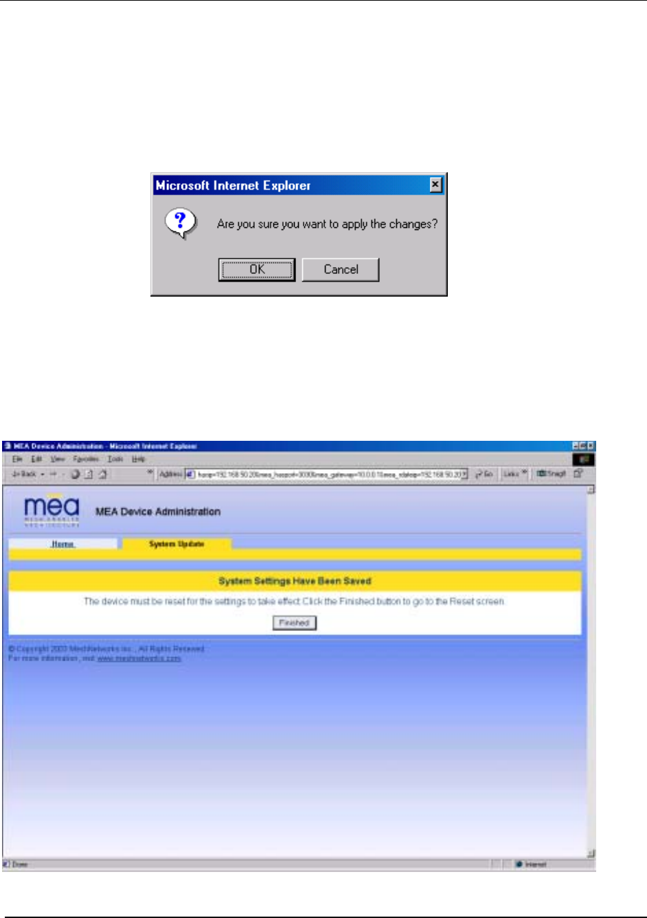
Click the Apply button to save the changes, or click the Cancel button to delete any changes. If
the Apply button is selected, a confirmation window will appear as in Figure 37. Click on the
OK button to continue or select Cancel to terminate the procedure.
Figure 37. System Settings Confirmation Message
If the Apply button is selected, the new values will be saved and Figure 38 will be displayed.
The changes will not take effect until the device is reset. Select the Finished button to navigate
to the Device Reset option.
Figure 38. System Settings Saved Message
33
MeshNetworks
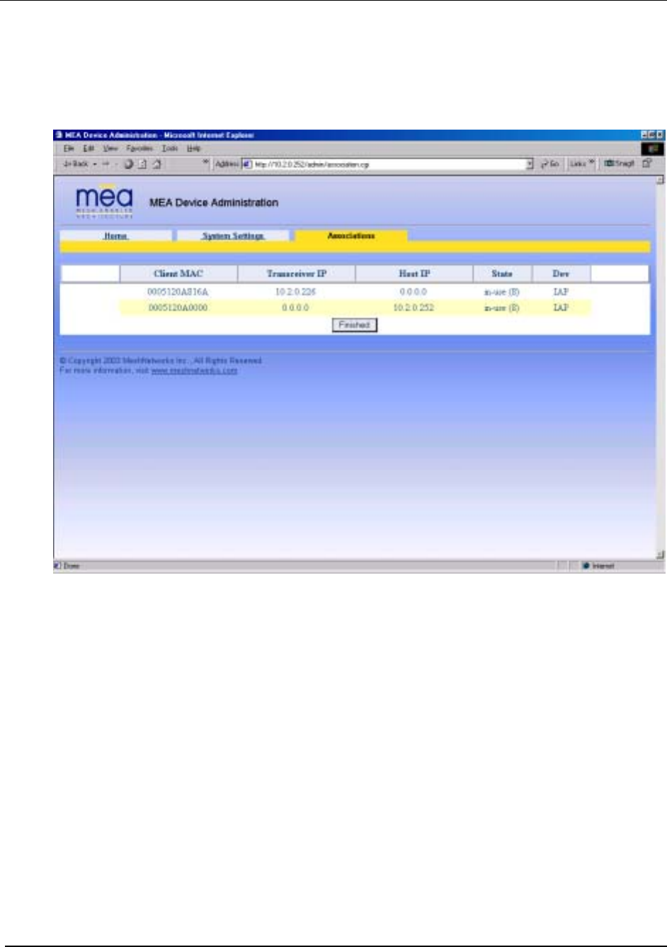
Associations Tab
The Associations Tab is an information only window as is shown in Figure 39.
Figure 39. MEA Device Administration Associations Tab
This window displays all devices currently associated with an IAP. There will always be at least
2 entries: one for the IAP’s SBC and one for the IAP’s transceiver. For every wireless router
and subscriber device currently associated with the IAP, there will be an additional entry in the
table.
Testing
Basic MiSC Tests
To verify the basic connectivity of the MiSC, conduct the following from the a computer
connected to the server subnet of the MiSC:
• Ping an IAP
• Ping the Core Router
• Ping the Edge Router
34

MEA Setup and Installation
Wireless System Tests
There are two basic tests to verify correct operation the system. The first test is to perform ping
tests to each device and the second test is to verify access the Internet.
Ping Test
From Device Manager, complete the following to verify correct operation of the system:
1.
2.
3.
4.
1.
Ping the SBC of the deployed IAPs
• From the Device Manager drop down menu, select Preferences/Use SBC Address
• For each IAP in the device tree, right click and select Ping Device
Ping the transceiver of the deployed IAPs
• From the Device Manager drop down menu, select Preferences/Use Transceiver
Address
• For each IAP in the device tree, right click and select Ping Device
Ping the transceiver of the deployed WRs
• From the Device Manager drop down menu, select Preferences/Use Transceiver
Address
• For each WR in the device tree, right click and select Ping Device
Ping the transceiver of each Subscriber Devices
• From the Device Manager drop down menu, select Preferences/Use Transceiver
Address
• For each SD in the device tree, right click and select Ping Device
Internet Test
If the MEA system has been configured to access the Internet, complete one of the two
following tests to verify correct network setup:
From a provisioned SD, start the web browser and enter a URL such as
http://www.MeshNetworks.com.
From a SD, open a DOS/cmd window and ping an URL, e.g., ping
www.meshnetworks.com.
2.
Default Addresses and Logins
The following are the default values for the system components. These may be updated during
installation.
Device Description Default
Core Router login password g0ld1
Core Router enable password g0ld11
Core Router IP address on Sever 172.31.0.2
35

MeshNetworks
Device Description Default
Core Router Wireless subnet IP address for Core
Router 10.0.0.1
Edge Router login password g0ld1
Edge Router enable password g0ld11
Edge Router IP address on Server 172.31.0.1
Sun Blade root password g0ld11
Sun Blade node name MeshManager
Sun Blade IP address for next-level hierarchical DNS
server (none)
Sun Blade IP address if Mesh VPN support is
provided 172.31.0.20
Sun Blade Secondary IP address for IAP rdate server 192.168.50.20
Sun Blade Secondary IP address for IAP HAS server 192.168.50.20
Sun Blade HAS port address 3030
Sun Blade Secondary IP address for IAP syslog
server 172.18.0.50
Sun Blade Server subnet DHCP range 172.31.1.1 to 172.31.1.254
Sun Blade Wireless subnet DHCP range 10.2.0.1 to 10.2.0.254
IAP Default Gateway 10.0.0.1
IAP IP address for rdate server 192.168.50.20
IAP IP address for HAS server 192.168.50.20
IAP IP address for syslog server 172.18.0.50
Subscriber
Device Default Gateway 10.0.0.1
Subscriber
Device DNS Server 172.31.0.20
36

MEA Setup and Installation
Section 4 - MAC Address Tables
This table has been included for recording the Ethernet MAC address and transceiver MAC
address for a set of EWR devices as a quick reference. These addresses will be required for
configuration and management of these devices.
IAP MAC Addresses
IAP MAC Address
00-05-12-0A-xx-yy
IAP ETH MAC Address
00-05-12-0A-xx-yy
WR MAC Addresses
WR MAC Address
00-05-12-0A-xx-yy
37

MeshNetworks
WMC MAC Addresses
WMC MAC Address
00-05-12-0A-xx-yy
38

MEA Setup and Installation
Section 5 - Site Selection/Deployment Guidelines
General Site Selection Guidelines
The IAP location(s) should be selected first since they have the additional requirement of routing
information back to the MiSC. This may be done via an Ethernet cable if the IAP and MiSC are
located within 100 meters (the max length permitted for standard Ethernet) of each other. If the
distance is greater than 100 meters, a mechanism for extending the Ethernet connection will be
required, e.g., using fiber or T1. (MeshNetworks recommends T1 backhaul equipment from
Net-to-Net Technologies.)
Once the IAPs have been placed, then the location of the WRs can be determined. Optimally,
the devices should be distributed such that a SD has no more than 3 hops to an IAP.
Power must be available for both IAPs and WRs. Both IAPs and WRs come standard with AC
power; DC power is available as an option.
Lastly, any local building/structure codes must be adhered to, as well as proper permits for
placing devices on structures that are not owned by the Network Operator (e.g., light poles).
MeshNetworks has developed the Location Analyzer tool to assist in the placement of
infrastructure. This tool runs on a Windows 2000 SD. The tool collects and analyzes data,
ultimately resulting in a deployment quality indication. Refer to the Location Analyzer
documentation for information on configuring and using this tool.
Antenna Guidelines
The location of fixed infrastructure antennas must address proper antenna orientation, selection
of elevation pattern for the specific locale, the avoidance of pattern distortion, and the impact of
obstructions and non-line-of-sight paths.
Polarization - Most of the antennas used in deployment will be vertically polarized. To maximize
line-of-sight signal reception, both the transmitting and receiving antennas should be vertically
oriented to avoid signal loss due to polarization mismatch. This applies to mobile and stationary
antennas. For example, placing a magnetically mounted vehicle antenna on a curved portion of
the vehicle roof so that its axis is not vertical risks a measure of signal loss at range, dependent
upon the specific elevation pattern details, as discussed above.
Local obstructions - Antennas should be mounted either above or below the plane of
obstructions as shown in Figure 40.
39

MeshNetworks
Obstruction
Antenna
Antenna
Obstruction
Figure 40. Antenna Mounting
Low gain rubber duck antennas that are mounted directly to Mesh transceivers are designed for
transmitting and receiving vertically polarized radiation. Hence, care must be taken to insure
close-to-vertical orientation of these antennas to avoid substantial signal loss due to polarization
mismatch. Additionally, attenuation sustained by use of these antennas inside vehicles can be
as high as 10 dB. Typically, losses are in the 4 to 7 dB range if the antenna is above the metal
can of the vehicle so that radiation and reception occur at window level.
Lab Checkout
Prior to deploying any equipment in the field, it is recommended to test the equipment in a lab
environment to ensure the equipment is functioning.
Step 1 - Verify MiSC
Set up the MiSC as discussed in the MiSC Assembly section. Attach a Windows computer to
the SMC switch. Verify that the following can be pinged: edge router, core router,
MeshManager. Refer to the Default Addresses and Logins section for the addresses.
Step 2 – Verify IAPs.
Using an Ethernet cable, attach the IAPs, one at a time, to the SMC switch. Using either the
MAC or ETH address on the IAP box for reference, use MeshManager to verify that the IAP
can be reached, and that it is obtaining an address from the DHCP server. Next, start an SD in
infrastructure mode, and ensure that it also receives an IP address from the DHCP server.
This verifies that both the SBC and the transceiver in the IAP are functioning.
Step 3 – Verify WRs
Connect an IAP as described in Step 2. Power up the WRs one at a time. Using the MAC
address on the WR box for reference, verify that the MeshManager console can reach each
WR, and that an appropriate IP address is displayed.
Step 4 – Verify PCMCIA cards
Connect an IAP as described in Step 2, Load a host computer with the WMC6300 drivers as
described in Loading and Verifying WMC6300 Software. Insert a WMC6300 card into the host
device. Start MeshTray. Verify that the status tab displays a valid IP address. Eject the
WMC6300 card utilizing the Unplug or Eject Hardware icon. Insert another WMC6300 card
and repeat the MeshTray test.
General Deployment Guidelines
It is recommended that field deployment follow the same steps as described in the Lab
Checkout Procedures. IAPs should be deployed first and verified as functional. Next the WRs
40

MEA Setup and Installation
should be deployed in a near to far pattern; in other words, WRs that are 1 hop from an IAP
should be deployed first, followed by WRs that are 2 hops from an IAP, etc. This allows the
functionality of each WR to be determined at the time of installation, thus eliminating any extra
truck rolls to trouble-shoot a WR.
41

MeshNetworks
Section 6 - Customer Service Information
If you have read this document, and made every effort to resolve installation or operation issues
yourself and still require help, please contact MeshNetworks Customer Support using the
following contact information:
MeshNetworks, Inc.
Attention: Customer Support
PO Box 948133
Maitland, Florida 32794-8133
Hours of Operation
Monday through Friday 8:00 AM – 5:00 PM (Eastern Standard Time)
Technical Support: (800) 311 – 3365 (USA)
(407) 659 – 5300
e-mail measupport@meshnetworks.com
42

MEA Setup and Installation
Section 7 - License and Warranty Information
MeshNetworks, Inc.
End User License Agreement
IMPORTANT NOTICE TO END USERS: This End User License Agreement (this Agreement)
is a legal agreement between the licensee of the Licensed Software being made available for
use with the MeshNetworks Equipment (either an individual person or a single legal entity, who
will be referred to in this Agreement as You) and MeshNetworks. Inc.
1 DEFINITIONS. In this Agreement, Licensed Software means the computer programs, in
machine-readable, interpreted, compiled or other form, furnished to You for use with the
MeshNetworks Equipment, whether owned or licensed by MeshNetworks, and including without
limitation, (i) computer programs residing on any medium and all materials or contained in any
download supplied by MeshNetworks in connection with the Licensed Software, (ii) related user
manuals and explanatory written materials or files (Documentation); and (b) upgrades, modified
versions, updates, additions, and copies of the Licensed Software, if any, provided to You by
MeshNetworks, either directly or indirectly (collectively, Updates). The MeshNetworks
Equipment means the equipment on which the Licensed Software is intended to operate.
Source means the party from whom you purchased the MeshNetworks Equipment and obtained
the Licensed Software. MeshNetworks means MeshNetworks, Inc., 485 N. Keller Road, Suite
250, Maitland, FL 32751. Support Services has the meaning set forth in Section 7.
2 LICENSE. As long as You comply with the terms of this Agreement, MeshNetworks grants
You a personal, non-exclusive, non-transferable (except as provided in Section 11) license to
use the Licensed Software (in object code form only) for Your own use in the operation on the
MeshNetworks Equipment. The license granted hereunder is perpetual.
3 SOFTWARE TITLE. MeshNetworks is not selling You the Licensed Software. Title to the
Licensed Software, including all translations, compilations, derivative works and copies remain
with MeshNetworks or its licensors, as the case may be.
4 INTELLECTUAL PROPERTY AND CONFIDENTIALITY. You acknowledge that the
Licensed Software and Documentation contain copyrighted material, trade secrets and other
material that is proprietary to MeshNetworks, and that except as expressly provided in this
Agreement, MeshNetworks retains all rights, title and interests in and to the Licensed Software
and all proprietary rights in it. You further acknowledge that unauthorized use of such material
may cause serious and irreparable loss or damage to MeshNetworks and its licensors, and
therefore you agree that in the event of a breach of this Agreement MeshNetworks will be
entitled to injunctive relief to restrain such breach, in addition to monetary damages and its
reasonable attorneys’ fees, charges and costs in enforcing the Agreement. You will keep the
Licensed Software, any backup copy of the Licensed Software and the Documentation strictly
confidential and will not disclose or provide them (or any information relating to them) to any
other person or entity. You will also take all reasonable steps to safeguard the Licensed
Software to ensure that unauthorized personnel do not have access to the Licensed Software,
and You will notify MeshNetworks of any unauthorized use of the Licensed Software. Except as
expressly stated herein, this Agreement does not grant You any intellectual property rights in
43

MeshNetworks
the Licensed Software and all rights not expressly granted herein are reserved by
MeshNetworks.
5 RESTRICTIONS. You will not:
5.1 Use the Licensed Software in conjunction with any other equipment or for any purpose
other than for the operation and monitoring of the MeshNetworks Equipment and for your
internal business purposes in accordance with the operating instructions MeshNetworks
or the Source may provide to you from time to time;
5.2 Decompile, reverse engineer, disassemble, translate or reduce the Licensed Software to a
human-perceivable form;
5.3 Modify, adapt, or translate or create derivative works based upon the Licensed Software
in whole or in part;
5.4 Lease, rent, sublicense, share, lend, distribute, disclose, network, or pledge the Licensed
Software to or for the benefit of any third party;
5.5 Use the Licensed Software in a client-server environment, electronically transmit the
Licensed Software from one computer to another or over a network or otherwise allow a
third party to remotely access or use the Licensed Software;
5.6 Transfer any of your rights in the Licensed Software or the Documentation to another
party;
5.7 Use the Licensed Software for any unlawful or harmful purpose;
5.8 Make copies of the Licensed Software, other than a reasonable number of copies of the
Licensed Software for back-up or archival purposes and such other copies as are
necessary for You to use the Licensed Software as described in the Documentation;
5.9 Remove or alter any trademark, copyright, confidentiality or other proprietary right notice
in the Licensed Software or Documentation or any copy made by You; or
5.10 Circumvent any access control mechanism that effectively controls access to the Licensed
Software for any purpose.
6 LIMITED WARRANTY.
6.1 Software Warranty. MeshNetworks warrants that the Licensed Software will operate
substantially in compliance with the Documentation for a period of ninety (90) days after
delivery to You. Any supplements or Updates to the Licensed Software provided to You
after the expiration of ninety (90) days limited warranty period are not covered by any
warranty or condition, express or implied. In the event of a breach of the foregoing
warranty, You must notify the Source within such 90-day period. In the event that you
notify the Source of a breach of the foregoing warranty within such 90-day period, the
Source will, at the Source’s option, either (i) use commercially reasonable efforts to
correct any substantial non-conformity, (ii) replace the non-conforming item of Licensed
Software, or (iii) return the fee paid by You for such item of Licensed Software. The
foregoing will be entire liability of MeshNetworks and the Source and your sole and
exclusive remedy for a breach under the foregoing limited warranty. Neither the Source,
nor MeshNetworks will have no liability under this warranty to the extent that (a) the
Licensed Software has been misused or exposed to environmental or operating conditions
beyond those specified by MeshNetworks, (b) the Licensed Software has been damaged,
altered by accident, neglect, misuse or other abuse, (c) the claimed defect has been
caused, in whole or in part, by a person or persons other than MeshNetworks, by other
products or software not provided by MeshNetworks, or by circumstances not under
44

MEA Setup and Installation
MeshNetworks' control, or (d) You fail to incorporate all error fix releases that
MeshNetworks or the Source has provided. In the event the Source fails to perform its
responsibilities as described in this Section 6.1 within a reasonable period of time,
MeshNetworks or one of its independent contractors will perform such obligations. The
warranty period, but not the scope of obligations described above, may be extended by a
written agreement between You and the Source.
6.2 DISCLAIMER OF PERFORMANCE WARRANTIES. EXCEPT AS SET FORTH IN
SECTION 6.1 ABOVE, THE LICENSED SOFTWARE IS LICENSED TO YOU AS IS.
MESHNETWORKS DOES NOT REPRESENT OR WARRANT, AND EXPRESSLY
DISCLAIMS ANY REPRESENTATION OR WARRANTY, THAT:
6.2.a THE OPERATION OF THE LICENSED SOFTWARE WILL BE UNINTERRUPTED OR
ERROR FREE; AND
6.2.b THE FUNCTIONS OR FEATURES OF THE LICENSED SOFTWARE WILL MEET
YOUR REQUIREMENTS, OR THAT THE LICENSED SOFTWARE WILL OPERATE IN
THE HARDWARE AND SOFTWARE COMBINATIONS SELECTED BY YOU. YOU
ASSUME ALL RESPONSIBILITY FOR THE SELECTION OF PRODUCTS AND THE
LICENSED SOFTWARE TO ACHIEVE YOUR INTENDED RESULTS, AND FOR YOUR
USE OF AND RESULTS OBTAINED FROM THE LICENSED SOFTWARE.
6.3 DISCLAIMER OF IMPLIED WARRANTIES. EXCEPT AS SET FORTH IN SECTION 6.1
ABOVE, THE LICENSED SOFTWARE IS LICENSED TO YOU AS IS.
MESHNETWORKS EXPRESSLY DISCLAIMS, TO THE MAXIMUM EXTENT
PERMITTED BY APPLICABLE LAW, ANY AND ALL REPRESENTATIONS AND
WARRANTIES, EXPRESS, IMPLIED, OR STATUTORY, INCLUDING
REPRESENTATIONS OR WARRANTIES OF NON-INFRINGEMENT OF ANY THIRD
PARTY INTELLECTUAL PROPERTY RIGHTS, OWNERSHIP, MERCHANTABILITY,
FITNESS FOR A PARTICULAR PURPOSE, QUIET ENJOYMENT, SYSTEM
INTEGRATION, AND DATA ACCURACY. MESHNETWORKS’ EXPRESS WARRANTY
WILL NOT BE ENLARGED, DIMINISHED OR AFFECTED BY, AND NO OBLIGATION
OR LIABILITY WILL ARISE OUT OF, THE RENDERING OF TECHNICAL OR OTHER
ADVICE OR SERVICE BY MESHNETWORKS OR THE SOURCE IN CONNECTION
WITH THE LICENSED SOFTWARE.
6.4 NO CONSEQUENTIAL DAMAGES. UNDER NO CIRCUMSTANCES WILL EITHER
PARTY BE LIABLE FOR ANY SPECIAL, INCIDENTAL OR CONSEQUENTIAL
DAMAGES ARISING IN ANY WAY OUT OF THIS AGREEMENT OR THE USE OF THE
LICENSED SOFTWARE AND DOCUMENTATION HOWEVER CAUSED (WHETHER
ARISING UNDER A THEORY OF CONTRACT, TORT (INCLUDING NEGLIGENCE), OR
OTHERWISE), INCLUDING, WITHOUT LIMITATION, DAMAGES FOR LOST PROFITS,
LOSS OF DATA, OR COSTS OF PROCUREMENT OF SUBSTITUTE GOODS OR
SERVICES. THE LIMITATIONS ON LIABILITY SET FORTH IN THIS SECTION WILL
APPLY NOTWITHSTANDING THE FAILURE OF ESSENTIAL PURPOSE OF ANY OF
THE LIMITED REMEDIES SET FORTH IN SECTION 6.1 ABOVE.
6.5 LIMITATION OF LIABILITY. THE TOTAL LIABILITY OF MESHNETWORKS, THE
SOURCE AND MESHNETWORKS’ LICENSORS ARISING OUT OF OR RELATING TO
THIS AGREEMENT WILL NOT EXCEED THE LICENSE FEES AND PURCHASE PRICE
RECEIVED BY THE SOURCE FROM YOU IN THE TWELVE (12) MONTHS PRIOR TO
THE EVENT GIVING RISE TO THE LIABILITY.
45

MeshNetworks
7 SUPPORT SERVICES. The Source may provide You with support services related to the
Licensed Software (Support Services). Use of Support Services is governed by the Source’s
policies and programs or in other materials from the Source. Any Updates or other
supplemental software code provided to You as part of the Support Services are considered
part of the Licensed Software and subject to the terms and conditions of this Agreement. You
acknowledge and agree that MeshNetworks and its licensors, contractors, resellers and
distributors may use technical information You provide to them as part of the Support Services
for its business purposes, including for product support and development.
8 INDEMNIFICATION. MeshNetworks will defend, indemnify and hold You harmless from any
liability arising from any third party claim or proceeding against You to the extent that such claim
or proceeding is based on an assertion that the Licensed Software infringes any issued United
States patent or any trade secret or copyright of any third party; provided, however, that You
notify MeshNetworks promptly in writing of any such claim or proceeding and give
MeshNetworks full and complete authority, information and assistance to defend such claim or
proceeding at the expense of MeshNetworks; and further provided that You give MeshNetworks
sole control of the selection of counsel and the defense of any such claim or proceeding and all
negotiations for its compromise or settlement. Should the Licensed Software become, or in
MeshNetworks’ opinion be likely to become, the subject of a claim of infringement,
MeshNetworks will have the right, at MeshNetworks’ option and expense, (i) to procure for You
the right to continue using the Licensed Software, or (ii) to replace or modify the Licensed
Software with a non-infringing version of substantially equivalent function and performance.
9 LIMITATION. MeshNetworks will have no liability to You hereunder for any infringement
based upon (i) the combination of the Licensed Software with other products not provided by
MeshNetworks; (ii) the use of other than a current, unaltered version of the Licensed Software;
(iii) the use of any derivative works, modification or improvement of the Licensed Software not
created by MeshNetworks; (iv) any use of the Licensed Software in the practice of a process not
specified by MeshNetworks. Section 8 and 9 state the sole, exclusive and entire liability of
MeshNetworks, and the sole, exclusive and entire remedy with respect to any claim of
intellectual property infringement by the Licensed Software.
10 TERMINATION. If You breach any provision of this Agreement, then MeshNetworks may, in
addition to any other remedies it may have under law, terminate any license granted hereunder
effective immediately without liability after ten (10) days written notice to You, and You will
promptly cease all use of the Licensed Software and will return to MeshNetworks all copies of
the Licensed Software. In such event, at the request of MeshNetworks you will certify in writing
that the original and all copies of the Licensed Software has been destroyed or returned to
MeshNetworks.
11 ASSIGNMENT AND MESHNETWORKS EQUIPMENT TRANSFER. You may not
sublicense or assign this Agreement or any interest or right granted herein without
MeshNetworks’ prior written consent. The Licensed Software is designed and configured for the
sole purpose of operating with the MeshNetworks Equipment, and accordingly this Agreement
will be automatically assigned on the sale or transfer of the MeshNetworks Equipment with
which the Licensed Software operates to the person or entity who takes title to such
MeshNetworks Equipment; provided, however, that such assignee or transferee abides by the
obligations and restrictions set forth in this Agreement.
12 GOVERNMENT LICENSEE. The MeshNetworks Equipment and Licensed Software and
accompanying documentation were developed at private expense and no part of them is in the
public domain. The Licensed Software is Restricted Computer Software and Commercial
Computer Software and if You are acquiring the Licensed Software for the United States
46

MEA Setup and Installation
Government, then it is acquiring only restricted rights in the Licensed Software and its
Documentation, all as defined in the applicable provisions of the Department of Defense Federal
Acquisition Regulation Supplement and the Federal Acquisition Regulations. Such unit will
include a restricted rights legend on the MeshNetworks Equipment and Licensed Software as
may be necessary to insure the limitation of rights acquired by the government.
Notwithstanding the foregoing, this Agreement will not become effective with respect to the
United States Government without MeshNetworks’ prior written approval.
13 EXPORT CONTROLS. This Agreement is subject to the laws, regulations, orders, and
decrees of the United States that may be imposed from time to time restricting the import/export
of the Products to/from the United States. You will not export or re-export the Licensed
Software, or any part of the Licensed Software, directly or indirectly, prohibited by or in violation
of the laws, rules or regulations of the United States or any applicable jurisdiction. Nor will You
export or re-export the Licensed Software, or any part of the Licensed Software, directly or
indirectly without first obtaining the required permission to do so from the applicable
governmental agencies.
14 COMPLIANCE WITH LICENSES. You agree that upon request from MeshNetworks or the
Source, You will within fifteen (15) days fully document and certify in writing that use of any and
all Licensed Software at the time of the request is in conformity with this Agreement or some
other valid license from MeshNetworks.
15 MISCELLANEOUS. This Agreement is governed by the laws of the state of Florida, United
States of America. The state or federal courts located in or having jurisdiction over Orlando,
Florida, United States of America will have exclusive jurisdiction over all maters pertaining to
this Agreement. If any term or condition of this Agreement is or will become invalid or
unenforceable, then such part will be ineffective to the extent of such invalidity only, without
affecting this Agreement’s remaining provisions. Those rights and obligation, which by their
nature are intended to survive the expiration or termination of this Agreement, will survive. The
remedies at law of either party in the event of default or impending default by the other party in
the performance of any terms of this Agreement will not be adequate, and such terms may be
specifically enforced by a decree for specific performance, injunction or other appropriate
equitable relief. The failure of MeshNetworks to enforce at any time any provision of this
Agreement will in no way be construed to be a present or future waiver of such provision, nor
will it affect MeshNetworks ability to enforce any provisions of this Agreement. This Agreement
is the entire agreement between the parties with respect to the subject matter set forth herein
and supersedes all prior oral written agreements between the parties with respect thereto and
may only be amended in writing by the parties.
47

MeshNetworks
Section 8 - FCC Regulatory Information
FCC Information
This device complies with Part 15 of the FCC Rules. Operation is subject to the following two
conditions: (1) this device may not cause harmful interference, and (2) this device must accept
any interference received; including interference that may cause undesired operation.
The IAP6300 (Intelligent Access Point) is an infrastructure device that is positioned at a fixed
location such as a building rooftop. The IAP6300 requires professional installation to ensure
that the installation is performed in accordance with FCC licensing regulations.
The MWR6300 (Wireless Router) is an infrastructure device positioned in a fixed location, such
as on a pole, wall, or rooftop. The MWR6300 requires professional installation to ensure the
installation is performed in accordance with FCC licensing regulations.
Federal Communications Commission (FCC) Statement:
This Equipment has been tested and found to comply with the limits for a Class A digital device,
pursuant to Part 15 of the FCC rules. These limits are designed to provide reasonable
protection against harmful interference in a commercial installation. This equipment generates,
uses and can radiate radio frequency energy and, if not installed and used in accordance with
the instructions, may cause harmful interference to radio communications. However, there is no
guarantee that interference will not occur in a particular installation. If this equipment does
cause harmful interference to radio or television reception, which can be determined by turning
the equipment off and on, the user is encouraged to try to correct the interference by one or
more of the following measures:
• Reorient or relocate the receiving antenna.
• Increase the separation between the equipment and receiver.
• Connect the equipment into an outlet on a circuit different from that to which the
receiver is connected.
• Consult the dealer or an experienced radio/TV technician for help.
Any changes or modifications not expressly approved by MeshNetworks could void the user’s authority to operate the equipment.
FCC RF Radiation Exposure Statement
CAUTION: This equipment complies with FCC RF radiation exposure limits set forth for
an uncontrolled environment. This equipment should be installed and operated with a
minimum distance of 2 meters between the antenna and your body.
1.
2. This Transmitter must not be co-located or operating in conjunction with any other
antenna or transmitter.
48

MEA Setup and Installation
Section 9 - Safety Information for the MEA Products
The Federal Communications Commission (FCC) with its action in ET Docket 96-8 has adopted
a safety standard for human exposure to radio frequency (RF) electromagnetic energy emitted
by FCC certified equipment. MeshNetworks’ MEA products meet the uncontrolled
environmental limits found in OET-65 and ANSI C95.1, 1991. Proper operation of this radio
according to the instructions found in this manual and the hardware and software guides on the
MEA CD will result in user exposure that is substantially below the FCC recommended limits.
• Do not touch or move the antenna(s) while the unit is transmitting or receiving.
• Do not hold any component containing a radio such that the antenna is very close to or
touching any exposed parts of the body, especially the face or eyes, while transmitting.
• Do not operate a portable transmitter near unshielded blasting caps or in an explosive
environment unless it is a type especially qualified for such use.
• Do not operate the radio or attempt to transmit data unless the antenna is connected;
otherwise, the radio may be damaged.
Antenna use:
• In order to comply with FCC RF exposure limits, dipole antennas should be located at a
minimum distance of 2 meters or more from the body of all persons.
Section 10 - Safety Certification
3041788
Conforms to UL STD ANSI/UL 60950 3rd Edition
Certified to CAN/CSA C22.2 NO. 60950-00
Equipment shall be suitable for use in Air pressure: 86kPa to106kPa.
CE Mark Certification
The CE mark is the official marking required by the European Community for all Electric and
Electronic equipment that will be sold, or put into service for the first time, anywhere in the
European community. It proves to the buyer or user that this product fulfills all essential safety
and environmental requirements as they are defined in the European Directives.
MeshNetworks Products are covered under the following product certification Europe:
ETSI EN 300 328 V 141 (2003-04)
49

MeshNetworks
50
Products covered - IAP6300, EWR6300 , WMC6300, and MWR6300
ETSI EN 301 489-1 (2002-08) and 301 489-17
Products covered - IAP6300, EWR6300 , WMC6300, and MWR6300
EN 55022:1998 and EN 55024:1998
Products covered - IAP6300, EWR6300 , WMC6300, and MWR6300
CENELEC EN 50360 and EN50371 – Specific Absorption Test - SAR
Products covered - WMC6300
The following countries are covered under the CE Mark:
Austria, Belgium, Demark, Finland, Germany, Greece, Ireland, Italy, Luxemburg, Netherlands,
Portugal, Spain, Sweden, UK
CE Marking on the product will gain you access to the European Economic Area (EEA). Some
countries may require a declaration of conformity, please check with your MeshNetworks sales
team for details.
An example of the CE Marking on a product label:
Alert
S
y
mbol
CE Mark
The alert symbol indicates that MeshNetwork’s products are not certified to operate in
France. France outdoor use is restricted to 10mW EIRP for band 2454 - 2483.5
MHz.