Zebra Technologies WMC6300704 PCMCIA Card User Manual VMM User s Guide
Zebra Technologies Corporation PCMCIA Card VMM User s Guide
Contents
VMM Users Manual

Vehicle Mounted
Modem
User’s Guide
Version 3.0
Copyright 2003-2004, MeshNetworks, Inc. All Rights Reserved

MEA VMM User’s Guide
Foreword
This document describes in detail the confidential and proprietary technology of MeshNetworks’
MEA™ Architecture. MeshNetworks’ products and technology are protected by US and
international patent and patent pending technology. This document represents the current MEA
design; the contents are subject to change at any time at the discretion of MeshNetworks, Inc.
MEA, MeshTray, and MeshNetworks’ logo are trademarks or registered trademarks of
MeshNetworks, Inc. All other product names and services identified throughout this publication
are trademarks or registered trademarks of their respective companies. No such uses or the
use of any trade name is intended to convey endorsement or other affiliation with this
publication.
Copyright © 2003-2004, MeshNetworks, Inc. All Rights Reserved.
iii

MEA VMM User’s Guide
Table of Contents
1 VEHICLE MOUNTED MODEM .............................................................................................1
1.1 Introduction.................................................................................................................1
1.2 What’s in the Box .......................................................................................................1
2 INSTALLATION REQUIREMENTS.......................................................................................2
2.1 Equipment...................................................................................................................2
2.2 Record MAC Address of the VMM6300 ....................................................................3
2.3 VMM6300 Assembly ...................................................................................................3
2.3.1 Deployment ....................................................................................................... 4
2.3.2 Deployment Tips................................................................................................ 4
2.3.3 Testing............................................................................................................... 4
3 INSTALLING THE MEA VEHICLE MOUNTED MODEM......................................................6
3.1 Device Administration: Configuring the VMM Devices...........................................6
3.1.1 Accessing the MEA Device Administration Web Pages .................................... 6
3.1.2 Configuring the Device .................................................................................... 10
3.1.2.1 Device Addressing....................................................................................... 11
3.1.2.2 Network DHCP Scheme .............................................................................. 11
3.1.2.3 Statically Provisioned Scheme .................................................................... 12
3.1.2.4 User Supplied Scheme................................................................................ 12
3.1.2.5 Setting the User Supplied IP Address ......................................................... 13
3.1.3 Resetting the VMM .......................................................................................... 15
3.1.4 Restoring Factory Settings – User Supplied Mode Limitations ....................... 17
3.1.4.1 VMM Reset-to-Default Recovery In User-Supplied Mode ........................... 17
3.1.4.2 Reset the Device Addressing Mode Using DeviceManager........................ 17
3.1.4.3 Reset the Device Addressing Mode via the Configuration Web Page......... 17
3.1.4.4 Reset the User-Supplied Parameters via the Configuration Web Page ...... 17
3.1.5 Restoring Factory Settings – Normal Operations ............................................ 18
v

MeshNetworks
3.1.6 Changing the Web Password .......................................................................... 20
3.1.7 Upgrading the Device Firmware ...................................................................... 22
3.2 External Device Provisioning..................................................................................24
3.2.1 Connecting to the Ethernet Port ...................................................................... 25
3.3 Infrastructure Requirements ...................................................................................25
3.3.1 VMM MAC Addresses ..................................................................................... 26
4 LICENSE AND WARRANTY INFORMATION ....................................................................27
4.1 Important Information ..............................................................................................27
5 FCC REGULATORY INFORMATION.................................................................................29
5.1 FCC Information .......................................................................................................29
vi

MEA VMM User’s Guide
List of Figures
Figure 2-1 VMM6300 Identification Label ............................................................................3
Figure 2-2. VMM External Connection Point .......................................................................3
Figure 3-1 Enter Network Password Initial Web Page Authentication Dialog .................7
Figure 3-2. MEA Device Administration Redirecting Web Page.........................................8
Figure 3-3. MEA Device Administration Home Page (Super User Login)..........................9
Figure 3-4. VMM Device Administration Configuration Page (Super User Login)..........10
Figure 3-5. Configuration Change Dialog...........................................................................13
Figure 3-6. System Update Save Completed Web Page ...................................................14
Figure 3-7. Device Reset Prompt Web Page ......................................................................15
Figure 3-8. Device Reset in Progress Page........................................................................16
Figure 3-9. Restore Factory Settings Web Page................................................................18
Figure 3-10. Confirm Changes Window for Restore Factory Settings ..........................19
Figure 3-11. Factory Settings Restored Web Page..........................................................19
Figure 3-12. Enter New Password Web Page...................................................................20
Figure 3-13. Confirm Changes Window for Enter New Password .................................21
Figure 3-14. Password Changed Confirmation Web Page..............................................21
Figure 3-15. Update Device Firmware Web Page.............................................................22
Figure 3-16. Confirm Upload Window for Firmware Update...........................................23
Figure 3-17. Firmware Upload Progress Web Page.........................................................23
Figure 3-18. External Device Provisioning Table.............................................................24
vii

MEA VMM User’s Guide
1 Vehicle Mounted Modem
1.1 Introduction
Thank you for purchasing the MEA Vehicle Mounted Modem (VMM). MEA is a wireless
communication system capable of supporting high data rate mobile communication at variable
rates of vehicular speeds.
The VMM (VMM6300) is a wireless modem that has been designed for permanent in-vehicle
mounting. It provides access to the MEA network via an Ethernet connection to mobile data
terminals, laptop computers, or any other device that has an Ethernet port. The VMM operates
on 12vDC and is rugged enough for installation in commercial and public safety vehicles. The
VMM provides the same functionality as the WMC6300 to the connected device, including geo-
location. (Mobile antenna and cabling not included.)
The VMM efficiently combines the functionality of a Meshnetworks subscriber device and client
modem in to a single cost-effective wireless network component. This makes it easy for any
Ethernet ready device to access a MeshNetworks Enabled Architecture (MEA™) mobile
broadband network. Computers, IP video cameras, sensors, signs, signals, etc. can all be
Mesh-Enabled to send and receive data at burst rates of up to 6 Mbps. All standard subscriber
device functionality including Multi-Hopping™, non-line of-sight communications and geo-
location services are fully supported.
The MEA Vehicle Mounted Modem allows connection of multiple IP addressable devices using
standard Ethernet connectivity. This allows devices that cannot accept the PCMCIA based
WMC3600 product to function on a MEA network without drivers in a transparent manner.
This document provides detailed installation and configuration instructions for use when
installing the MEA VMM.
1.2 What’s in the Box
Each MEA VMM is a full-featured wireless networking device. The following is a list of the items
provided with each VMM:
• MEA Vehicle Mounted Modem
• 15 feet 18 AWG wire, rated for 12 VDC with 2 amp in line fuse
• VMM cable connector (end 1): Switchcraft EN3C2F
• VMM cable connector (end 2): Molex 19121-009 spade lugs
1

MeshNetworks
2 Installation Requirements
NOTE: All Intelligent Access Points (IAPs) on the MEA network require a software upgrade to
support VMM Devices.
The MEA Vehicle Mounted Modem External will require the following in a typical installation:
• 12 VDC Power from vehicle or other direct current power supply
• A Hub or Switch (if more then 1 Ethernet device will be used)
• Antenna and RF cabling appropriate for use in the 2.4 Ghz band.
2.1 Equipment
A VMM6300 is used similarly to a subscriber device within a MEA network. A VMM6300 will be
used with MeshNetwork’s infrastructure devices: IAP6300 and MWR6300. MeshManager
software is used to manage a VMM in the MEA network.
The following list defines the standard MEA hardware components to install a VMM:
• VMM Box with N-type Antenna Connector
• 15 feet 18 AWG wire, 12 VDC with 2 amp in line fuse
• Trunk Mounting Bracket
The Network Operator must supply the following:
• Mounting Location
• Power Source (12V DC)
• Hand tools for bracket installation
Optional Equipment:
• An Antenna Cable and connector must be ordered separately.
• Antenna is N-Type connector
• MeshNetworks SKU: MEA-MM0-VMM
• Antenna Options are the following:
Manufacturer Part Number Gain Usage
Maxrad BMMG2400ML195MSMA 0 dBi Mobile
Antenex TRA24003 3 dBi Mobile
2
MEA VMM User’s Guide
2.2 Record MAC Address of the VMM6300
The transceiver and SBC (Ethernet) MAC addresses are recorded on the label located on front
side of the VMM unit.
Record these numbers in the MAC Address Table in Section 3.3.1, because they will be
required later to configure and provision the device.
Figure 2-1 VMM6300 Identification Label
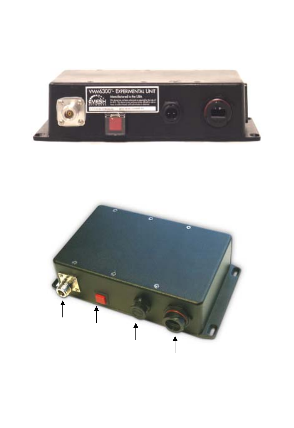
2.3 VMM6300 Assembly
The VMM6300 Assembly shows the external connection points on a VMM6300 box.
N-Type
Antenna Power
Reset
Power
Connect Ethernet
(Crossover MDI-X)
Figure 2-2. VMM External Connection Point
3
MeshNetworks
Install the VMM using the following procedure:
1.
2.
3.
4.
5.
Mount the VMM box in a suitable location in a vehicle. The device is not water proof. The device
should be reasonable protected from moisture and other exposed outdoor environments. Refer
to the mounting procedure in the assembly section of this document.
Connect the antenna to the N-type connector .
Insert the Power Plug into Power Connector.
Verify the MAC address and ETH address has been recorded in Section 3.3.1, as it will be
required to configure and test the device.
The Test Port is unused during deployment.
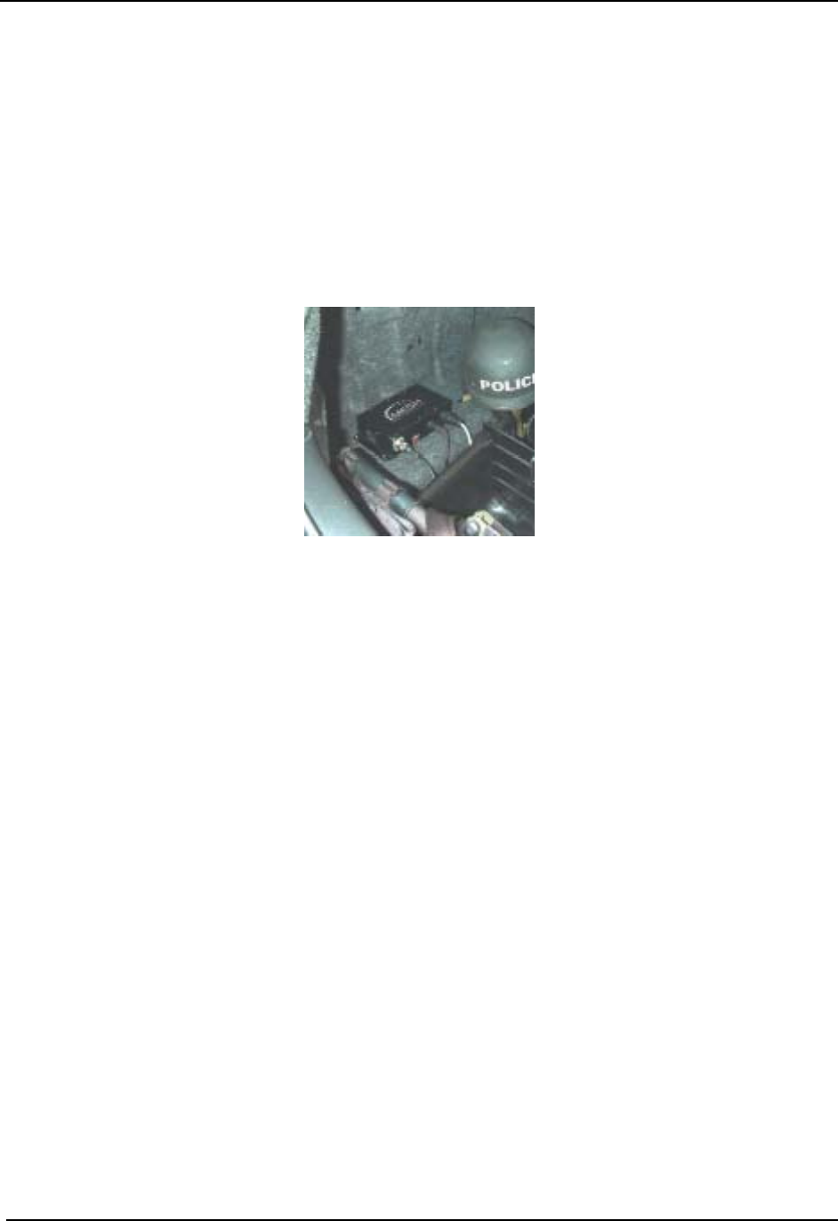
Figure 2-3 VMM6300 Trunk Mounting
2.3.1 Deployment
When deploying the VMM6300, the antenna should be a minimum of 30 inches from any nearby
metal poles to avoid distortion of the RF pattern. The antenna must have a separation distance
of at least 2 meters from the body of all persons and must not be co-located or operating in
conjunction with any other antenna or transmitter. Users and installers must be provided with
antenna installation and transmitter operating conditions to satisfy RF exposure compliance.
Typically, Vehicle Mounted Modems are distributed within a network and are used as subscriber
devices. A rule of thumb is to deploy 2-3 hop networks to optimize range, latency, and
throughput to subscriber devices.
The VMM6300 installation location must provide applicable DC power for the device.
2.3.2 Deployment Tips
Locate the antenna to minimize multipath:
Minimize interference from nearby transmitters
Maximize chance of a direct line of sight connection to other devices.
The antenna supplied is designed to be mounted vertically
2.3.3 Testing
Verify the operation of the VMM6300 using the following procedure:
1. Apply power to the VMM6300 – power reset button will be illuminated to red.
4

MEA VMM User’s Guide
2. Obtain the transceiver MAC address and the ETH address that was recorded in Section 3.3.1.
The address will be in the format 00-05-12-0A-xx-yy for the transceiver and 00-05-12-30-xx-yy for
ETH.
3. From MeshManager, display devices using the MAC address.
4. Select the appropriate VMM in the device tree, and then ping the device (right click and select
ping).
A successful response to the ping command verifies that the VMM is communicating to the
infrastructure devices.
5

MeshNetworks
3 Installing the MEA Vehicle Mounted Modem
3.1 Device Administration: Configuring the VMM Devices
The VMM provides network access to one or more IP devices connected to the Ethernet port of
the VMM. In order for the VMM to provide service to the IP devices, some configuration must be
done prior to connecting the IP devices.
The VMM serves as a default gateway for the attached IP devices. Because some devices
expect the default gateway to reside on the local subnet, the address that the VMM uses for
gateway service (on the wired interface) must be configurable. Some consideration should be
used in selecting a gateway address for the VMM.
The local default gateway address is used only on the wired interface, and is only visible to the
attached IP devices. It is not advertised to the wireless network, and the network cannot access
the VMM using this gateway address. The VMM has another IP address for the wireless
interface that can be used to access the VMM from the network. Because is gateway address is
limited to the local wired interface, the same address could be used for the gateway service in
several VMM devices. The local gateway should be a part of the overall subnet chosen for your
mēa network.
When selecting IP addresses, care must be taken to ensure that the selected IP address does
not conflict with any other devices or the chosen Local Gateway service address on the MEA
network.
3.1.1 Accessing the MEA Device Administration Web Pages
To modify the IP configuration for the VMM using the web interface, you must know the IP
address assigned to the wireless interface of the VMM. The IP address can be determined
from MeshManager, or from the DHCP server (once the device is configured for DHCP). The
default IP address for the VMM wireless interface is derived from the transceiver MAC address
(10.xx.yy.1, where the MAC address is 00:05:12:0A:XX:YY), similar to the default IP addresses
described in Section 3.2.
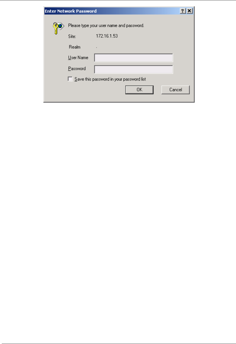
Once the IP address is known, you can access the web page of the device. Point your web
browser to the IP address of the VMM. In the examples following, the VMM address is
172.16.1.53, and the web page would be found at http://172.16.1.53/.
6
MEA VMM User’s Guide
Figure 3-1 Enter Network Password Initial Web Page Authentication Dialog
The username is admin, and the default (initial) password is admin.
The password for the admin account should be changed during installation.
The device has two accounts for the web pages - an administrative account (username:admin,
default password:admin), and an access account (username: monitor, default password:
monitor). The administrative account must be used for provisioning the device, and the access
account may be used for monitoring the status of the device.
The installation procedure described here requires administrator access. Alternatively, all of the
parameters that are provisioned via the web page may be provisioned via MeshManager
instead.
The administrator has the ability to change the password for the access account.
NOTE: If you are running a VMM as a standalone device, the configuration web page can be
reached by connecting a PC to the wired interface.
7
MeshNetworks
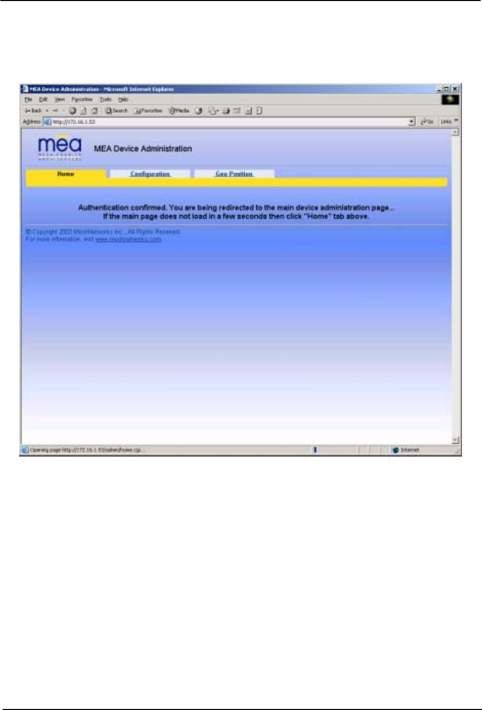
After the login authentication has been completed, the web browser will display a redirecting
page, and your browser will automatically transition to the home web page for MEA Device
Administration.
Figure 3-2. MEA Device Administration Redirecting Web Page
8
MEA VMM User’s Guide
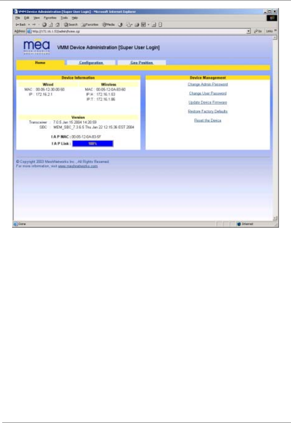
Figure 3-3. MEA Device Administration Home Page (Super User Login)
The MEA Device Administration home page provides you with some basic information about
the device, including the IP addresses assigned to the device, the MAC addresses of the
device, the firmware revision number, and the reported link quality for the link to the IAP. In
addition, links are provided to web pages for device configuration, password management,
firmware upgrades, device reset, and restoring the factory default configuration.
9
MeshNetworks
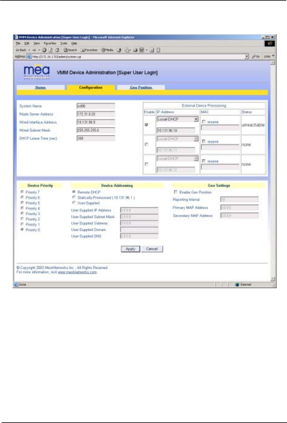
3.1.2 Configuring the Device
Once you have accessed the MEA Device Administration home page, click on the
Configuration tab to display the IP address configuration.
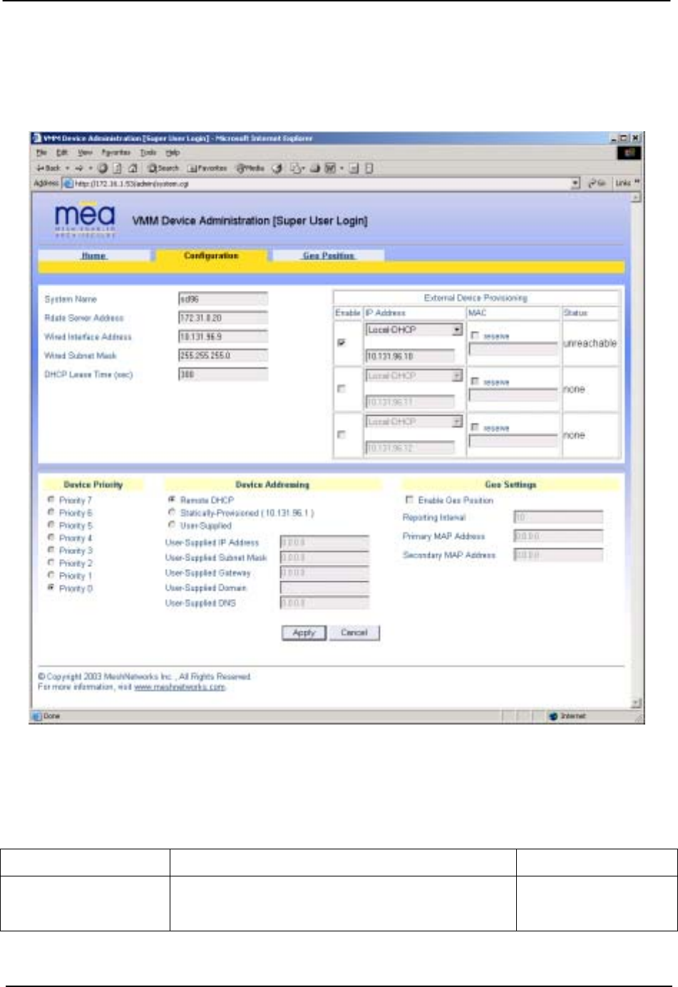
Figure 3-4. VMM Device Administration Configuration Page (Super User Login)
The VMM Device Administration (Super User Login) Configuration page will allow you to change
the configuration of the VMM. The fields displayed on this page are described below.
Field Name Field Description Field Default Value
System Name This is the name of the device as shown by
MeshManager
Assigned by
Network
Administrator
10

MEA VMM User’s Guide
Field Name Field Description Field Default Value
RDATE Server IP
Address
The IP address of the RDATE server. This is
usually the MiSC when operating in
infrastructure mode. The RDATE server
provides the current date to the VMM. The
VMM can operate without an RDATE server.
172.31.0.20
Wired Interface
Address
The VMM will tell the attached Ethernet devices
to use this address for the default gateway, and
the VMM will use the address when accessing
the local Ethernet segment.
MAC-derived
Wired Interface
Subnet Mask
This is the subnet mask for the local Ethernet
segment.
255.255.0.0
DHCP Lease Time This is the duration (in seconds) of the DHCP
leases that the VMM offers to the attached
Ethernet devices.
300
Device Priority The Device Priority provisioning area allows the
operator to set the priority assigned to wireless
messages transmitted by this device.
Levels 0-7 are
available. The
number of priority
levels for your
configuration is set
by the Network
Administrator
Geo Settings The Geo Settings area allows the operator to
enable and disable the Geo Reporting feature
(if provisioned), as well as control the
frequency of reports and provision the
destination server to which those Geo reports
will be sent.
NA
The External Device Provisioning frame of this web page is described in Section 3.2.
A similar screen will be displayed for the access account (the web page will indicate Normal
User Login). Normal users can change only those settings for which they have system
privileges.
3.1.2.1 Device Addressing
With mea Release 3.0, the concept of modes has been replaced by a Unified Modes of
operation addressing scheme. The concept of unified modes of operation centers on the current
state of network communication: Associated State and Unassociated State. There are three
addressing schemes which allow the IT manager increased flexibility in deployment.
3.1.2.2 Network DHCP Scheme
Operation under the Network DHCP scheme is similar to that of Release 2 in Infrastructure
Mode. The primary difference is users are now allowed to temporarily wander outside of the
network infrastructure without losing connectivity.
Network DCHP requires that the VMM device be configured to request an address from a
11

MeshNetworks
DHCP server and the inclusion of a DHCP server in the core network configuration to answer
these requests. With Network DHCP selected, the VMM will send DHCP requests for its own
address to the core network once it becomes associated and establishes communications with
the infrastructure.
The server may be configured by the operator to hand out temporary or static leases. The VMM
must associate and acquire an address from the network before establishing communications.
Once a lease has been granted, the address may be dragged out of network coverage for the
remainder of the lease or, if a static lease was granted, until the next power cycle. If the lease
expires or the user cycles power while outside of network coverage, the user will again lose the
ability to communicate with the wireless network.
This scheme is best for a larger, closely managed network of subscribers who don't need to
communicate or communicate only briefly outside of network coverage.
3.1.2.3 Statically Provisioned Scheme
Operation under the Statically Provisioned scheme is similar to that of Release 2 in Peer-to-
Peer Mode. The primary difference is that addresses are configured by the network operator
rather than hashed from the MAC address. This serves to eliminate the 10.x.x.x limitation on the
network range.
When operating under the Statically Provisioned scheme, the VMM device will use provisioned
DHCP-like information to establish an IP address for use in the wireless network.
This scheme does not require a DHCP server on the core network.
It should be noted that a DHCP server can still exist on the network to hand out addresses to
other nodes using the Network DHCP Scheme as long as the server's address range does not
conflict with addresses assigned to devices using the Statically Provisioned or User Supplied
Schemes.
The IP addresses and options used are configurable per-device using MeshManager. The
provisioned address may be freely used to communicate while associated or unassociated.
The operator must ensure that the provisioned addresses are routable and do not conflict with
any other addresses in use. The operator is free to provision any option ordinarily provisioned
by a DHCP server (subnet mask, DNS, etc.) through programming of the appropriate fields in
each device using MeshManager.
This scheme is ideal for a managed network of users who regularly need to communicate inside
and outside of network coverage or for a network lacking a DHCP server.
3.1.2.4 User Supplied Scheme
Operating under the User Supplied scheme, the VMM device is configured to use a fixed IP
address and subnet mask. The user is responsible for configuring options that would otherwise
be configured by a DHCP server.
It is also up to the user to ensure that the assigned address is routable on the core network (if
core network access is needed) and that it does not conflict with other addresses in use. This is
analogous to and carries the same caveats as plugging an Ethernet card into a LAN and
manually assigning an address to the card.
The user is free to communicate while associated or unassociated. This scheme is ideal for
small, unmanaged networks lacking a DHCP server.
12
MEA VMM User’s Guide
All of these schemes may be assigned per device, either by the user or by the network
manager. The network manager can also limit the user-selectable schemes or force a specific
scheme. Devices in each of these schemes can interoperate and communicate with each other,
so long as the assigned addresses do not conflict and are mutually routable.
3.1.2.5 Setting the User Supplied IP Address
In order to set the user-supplied IP address for the VMM, the User-Supplied radio button must
be selected. At that point, the user may enter an IP address, subnet mask consistent with the
existing network. The user should also enter the IP address of the default gateway and DNS
server, as well as enter the domain name.
Note that this configures the user-supplied address for the VMM device. To configure addresses
for ethernet clients, please refer to the description of the External Device Provisioning frame of
this web page in .
A similar screen will be displayed for the access account (the web page will indicate Normal
User Login). Normal users can change only those settings for which they have system
privileges.
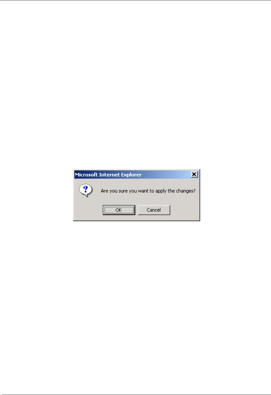
When the desired configuration has been completed, click on the Apply button on the Device
Addressing panel on the Device Administration Configuration Page. You will be prompted to
verify that the changes to the configuration are correct before the changes are actually applied.
Figure 3-5. Configuration Change Dialog
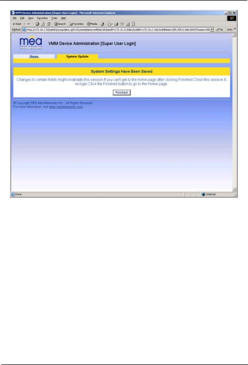
When you click on the OK button, the configuration will be saved in Flash. The System
Settings Have Been Saved message on the System Update Save Completed page will then
confirm the changes have been saved.
13
MeshNetworks
Figure 3-6. System Update Save Completed Web Page
After the settings have been saved, click the Finished button. Your web browser should return
to the MEA Device Administration home page. A reboot of the device is not required for the
changes to take effect.
14
MEA VMM User’s Guide
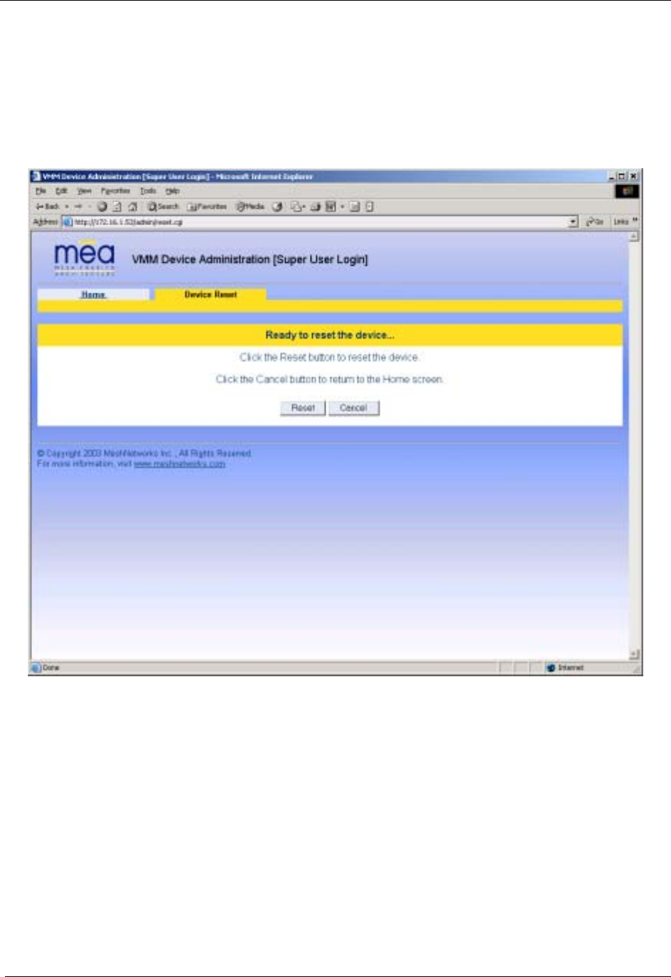
3.1.3 Resetting the VMM
Although you should not have to reset the VMM device, the device can be commanded to reset
via the web pages. In order to reset the device, return to the MEA Device Administration home
page, and click on the Reset the Device link in the Device Management panel.
The web page displayed will allow you to reset the device.
Figure 3-7. Device Reset Prompt Web Page
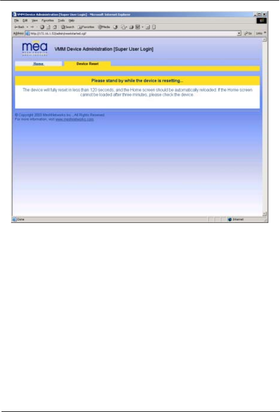
Once you have commanded the device to reset, the following screen will be displayed. Your
browser will delay for a short time, then transition to the home page once more.
15
MeshNetworks
Figure 3-8. Device Reset in Progress Page
NOTE: After the completion of the reset, you may experience a significant delay when bringing
up another web page. Please be patient.
16

MEA VMM User’s Guide
3.1.4 Restoring Factory Settings – User Supplied Mode Limitations
NOTE: In Release 3.0, there is a known issue that arises if the selected device addressing
mode is User-Supplied when the user restores the factory default settings for the
VMM. The following options are offered as a way to recover from this limitation.
3.1.4.1 VMM Reset-to-Default Recovery In User-Supplied Mode
The factory default settings for the User-Supplied parameters cannot be routed (i.e. 0.0.0.0).
When the non-routable values are applied, the network connection between the attached
ethernet devices and the core network becomes disabled.
There are three options available to recover from this situation and restore the connection to
the core network.
3.1.4.2 Reset the Device Addressing Mode Using DeviceManager
DeviceManager will be able to manage some but not all of the device parameters at this time.
The network operator may change the selected device addressing mode via DeviceManager to
either Remote-DHCP or Statically-Provisioned.
3.1.4.3 Reset the Device Addressing Mode via the Configuration Web Page
Because the factory default settings were restored, the VMM will offer one IP address via
DHCP. This address will be in the form 10.xx.yy.10, where xx and yy are based on the
transceiver MAC address as described in the VMM User’s Manual. The VMM will be accessible
via the 10.xx.yy.9 address, also described in the VMM User’s Manual. Once an ethernet device
has been attached to the VMM, the configuration web page may be accessed at the 10.xx.yy.9
address and the device addressing mode may be changed to either Remote-DHCP or
Statically-Provisioned.
Please be aware that the access password for the web page will have also been reset.
3.1.4.4 Reset the User-Supplied Parameters via the Configuration Web Page
If the allowed device addressing modes were restricted to User-Supplied, the user may still
connect to the VMM (as described above) and access the configuration web page. The User-
Supplied parameters may then be set to usable values.
17
MeshNetworks
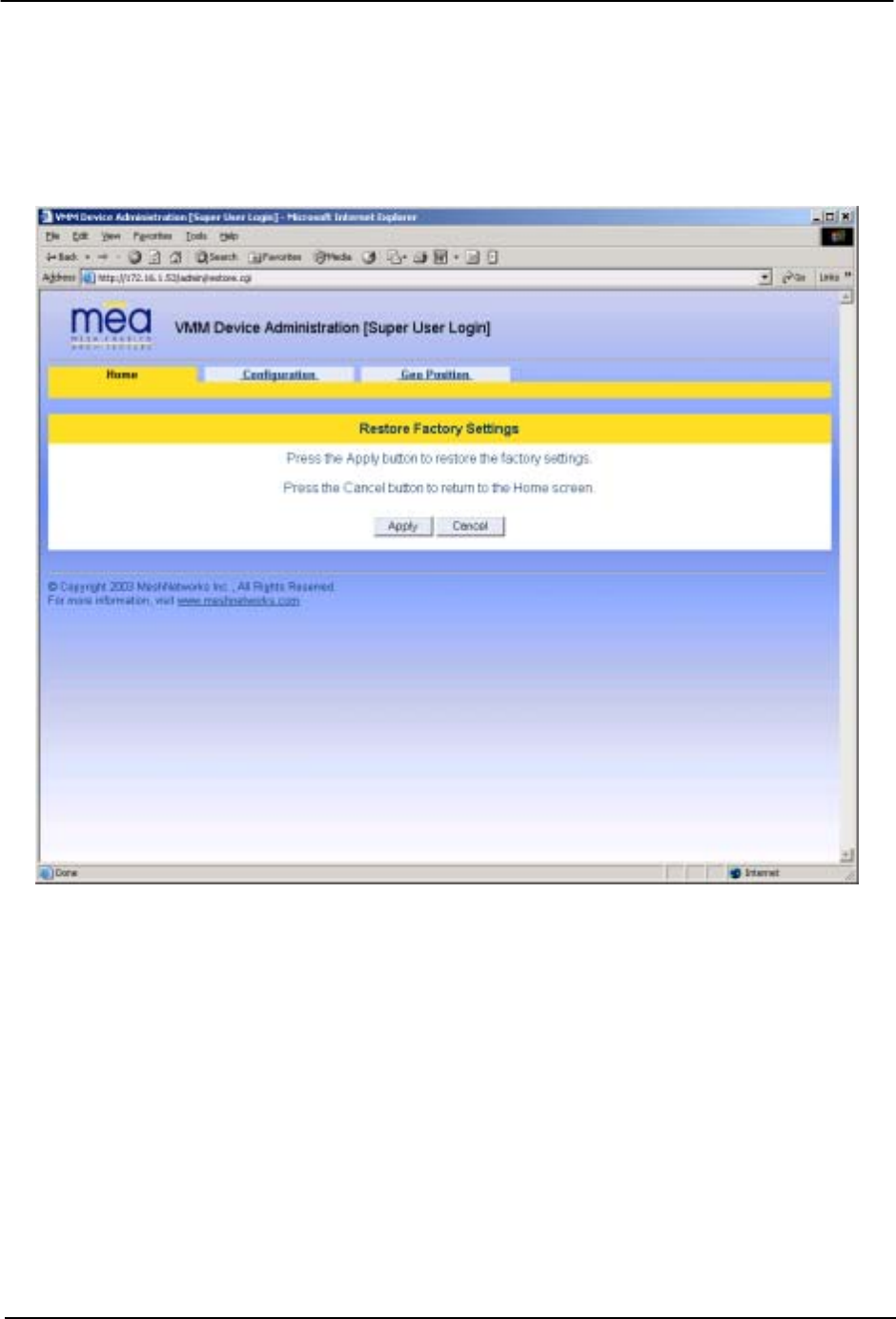
3.1.5 Restoring Factory Settings – Normal Operations
When the Restore Factory Defaults function is selected from the VMM Device Administration
Home Page, the device will present the following web page.
Figure 3-9. Restore Factory Settings Web Page
The Restore Factory Defaults function allows the operator to return the device to factory
defaults. This change will include the web password for the administrator and access accounts.
This will also return the local IP addresses to the default MAC-derived values.
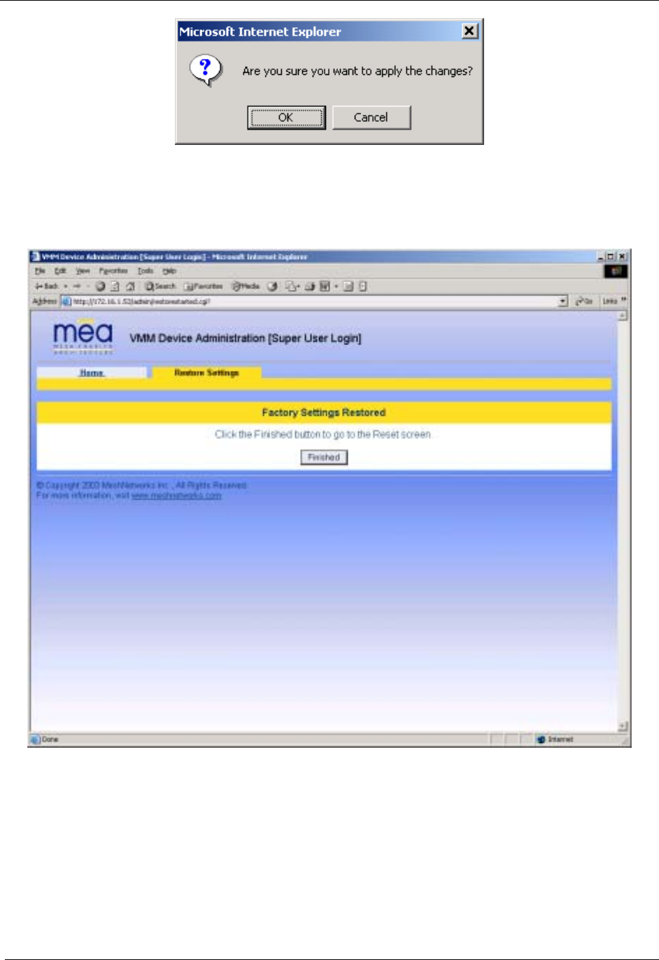
The confirmation window will be displayed. Click on the OK button to confirm the action.
18
MEA VMM User’s Guide
Figure 3-10. Confirm Changes Window for Restore Factory Settings
The Factory Settings Restored page will be displayed.
Figure 3-11. Factory Settings Restored Web Page
Click on the Finished button to complete the reset procedure.
19
MeshNetworks
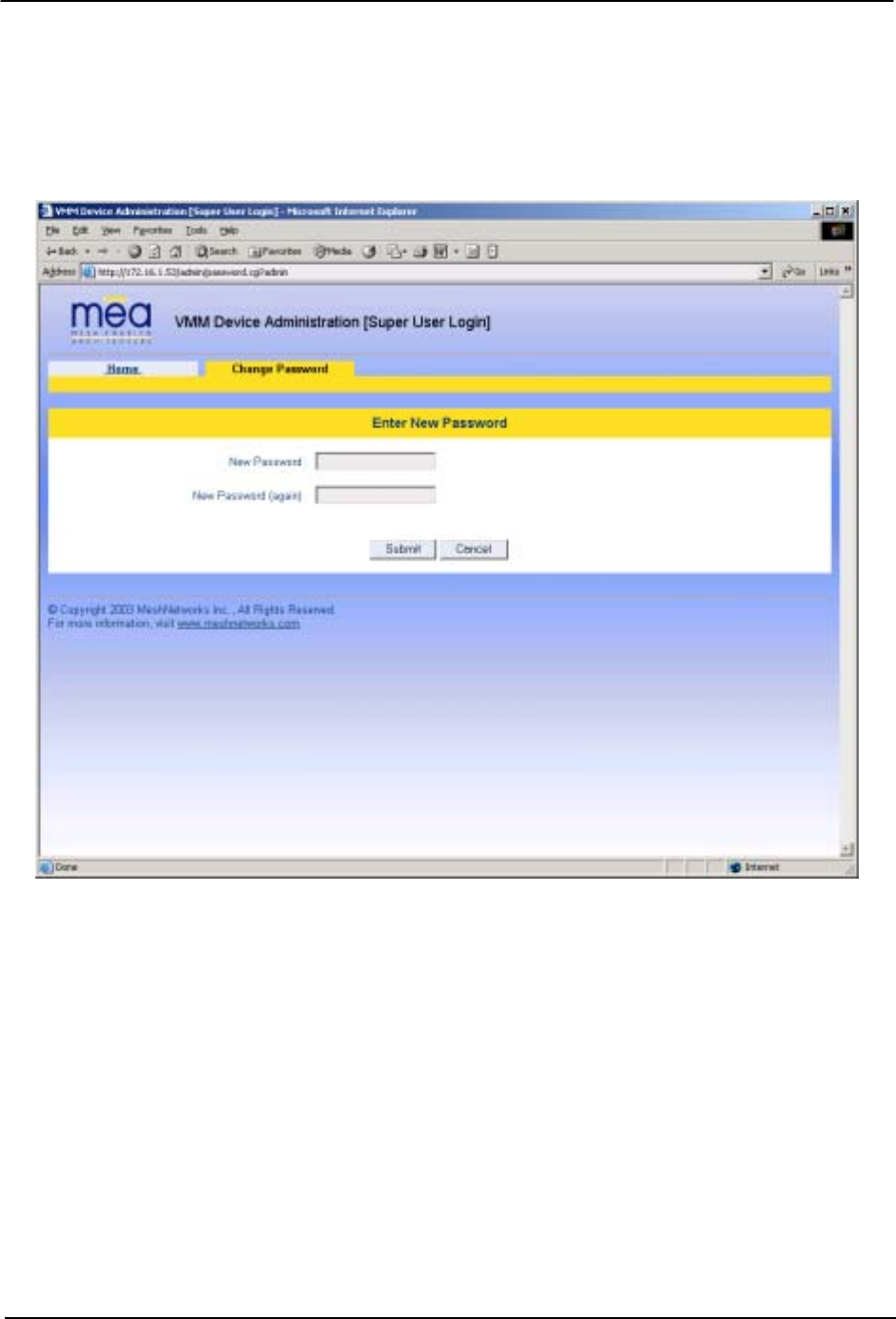
3.1.6 Changing the Web Password
When the Change Admin Password function is selected from the VMM Device Administration
Home Page by the administrator, or the Change User Password function is selected, the device
will present the following web page:
Figure 3-12. Enter New Password Web Page
The operator is expected to enter a new password for the web account and click on the “submit”
button. Once the password entry is complete, the device will prompt the operator for
confirmation of the change.
20
MEA VMM User’s Guide
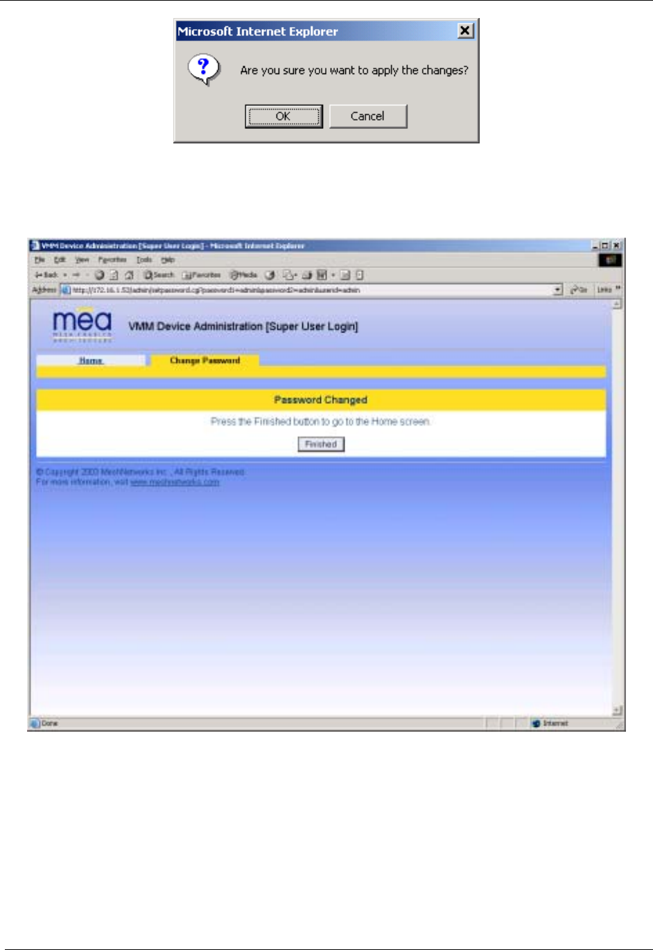
Figure 3-13. Confirm Changes Window for Enter New Password
When the operator confirms the change, the new password will be stored in flash, and the
device will present a status screen indicating that the change was successful.
Figure 3-14. Password Changed Confirmation Web Page
21
MeshNetworks
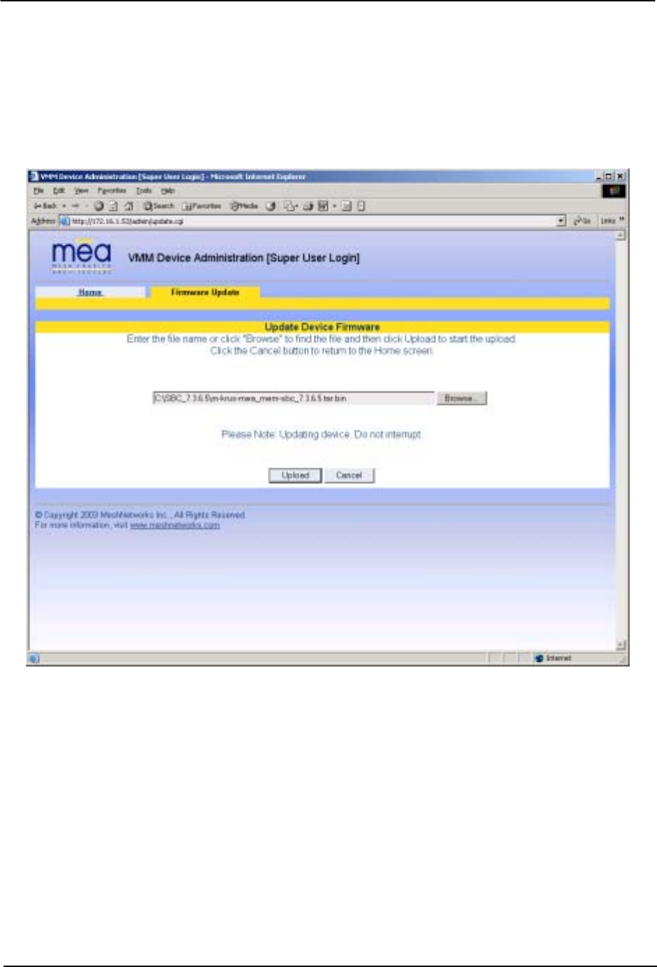
3.1.7 Upgrading the Device Firmware
The web interface for the device also provides the ability to upgrade the firmware on-site. To
use this feature, you must have an upgrade file from a released upgrade package.
When the Upgrade Device Firmware function is selected from the MEA Device Administration
Home Page, the device will present the following web page:
Figure 3-15. Update Device Firmware Web Page
This page allows entry of the name (and path) of the upgrade file. Once the correct filename has
been entered, the device will prompt for confirmation:
22
MEA VMM User’s Guide
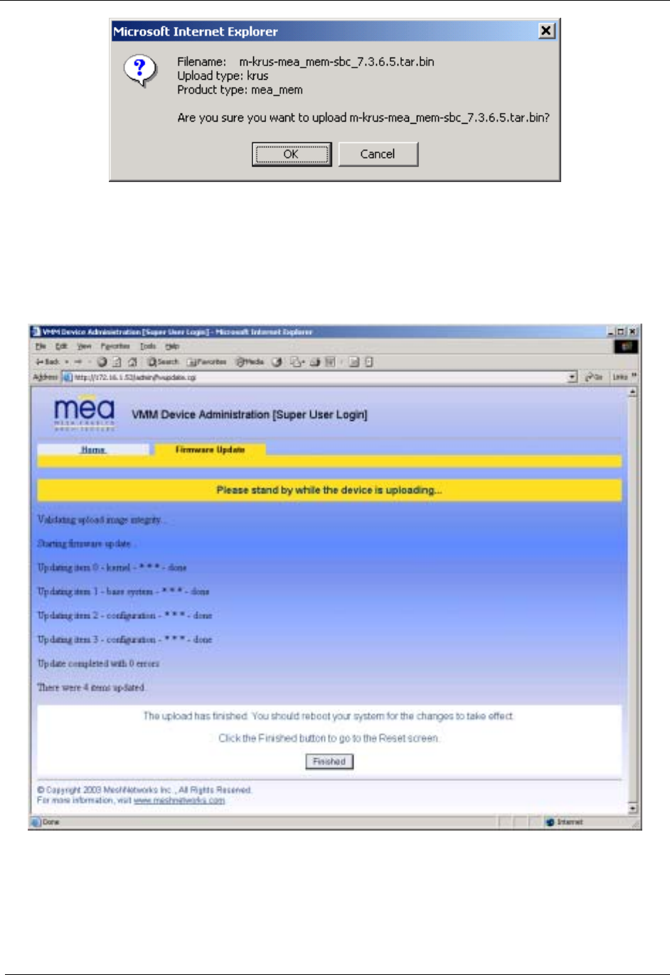
Figure 3-16. Confirm Upload Window for Firmware Update
Once the filename has been confirmed, the web browser will transmit the file to the device, and
the device will present an upgrade progress screen. This page will indicate the current stage in
the upgrade process.
Figure 3-17. Firmware Upload Progress Web Page
Once the upgrade is completed, the device must be reset. The Finished button will transition the
web browser to the reset screen.
23
MeshNetworks
3.2 External Device Provisioning
Figure 3-18. External Device Provisioning Table
The External Device Provisioning table is used to configure addresses for the attached nodes
on the local ethernet segment. Up to three addresses are provisioned.
The Enable checkbox indicates this row contains a valid address. Any address can be
disabled by clearing the checkbox. The pull-down menu options indicate whether this address
will be offered via the local DHCP service (“Local-DHCP”) or not (“Statically-Provisioned”).
The Statically-Provisioned setting is used to support devices that do not use DHCP to acquire
an address.
The MAC address field is used for Local-DHCP addresses, so that the IP address can be
reserved for a specific device. The reserved checkbox must be marked for this kind of IP
address reservation. The Status field indicates whether the provisioned IP address was
detected (via a ping) when the web page was brought up.
24

MEA VMM User’s Guide
The IP addresses default to values based on the transceiver MAC address of the device. The
derivation is described below. By default, only the first IP address is enabled (for local-DHCP),
and no addresses are reserved for specific MAC addresses.
Please make sure to check the checkbox for the client IP addresses you have entered. Client
2 and Client 3 are not enabled by default. In this example, the EWR wired interface is assigned
the IP address 172.16.2.1. This address is hidden from the core network and the IAP will not
route for this address. The core network must use the 172.16.1.37 address to access the EWR
(which is the address obtained via MeshManager).
The EWR has two interfaces and must use two IP addresses. The wireless network must use
the IP address on the wireless interface because that is the address for which the IAP will
proxy and advertise. The same address will be accessed by the DeviceManager when using
MeshManager.
The wired interface address will be used by the EWR as the gateway address for the local
ethernet segment. The wired subnet mask is configurable so that the user may select a more
restrictive subnet on the local ethernet segment than what is normally provided to the wireless
subscribers.
The MAC-derived default values are a means to ensure that these devices are likely to work
out-of-the-box. The IP addresses are derived as follows:
Transceiver MAC address: 00:05:12:0A:XX:YY
Derived MAC addresses:
Local gateway: 10.xx.yy.9
Client1: 10.xx.yy.10
Client2: 10.xx.yy.11
Client3: 10.xx.yy.12
Where XX and YY are hex values (from the transceiver MAC address), and the lowercase xx
and yy are the same values in decimal. For example, an EWR with transceiver MAC address of
00:05:12:0A:80:20 would have a default local gateway address of 10.128.32.9.
The user is encouraged to change these addresses upon installation.
3.2.1 Connecting to the Ethernet Port
If only one device is to be connected to the VMM, you can connect directly to the device using
an Ethernet cable.
If you are going to connect more than one device to the VMM, you will need to connect a hub to
the VMM, and connect the other devices to the hub.
3.3 Infrastructure Requirements
When in infrastructure mode, the MEA Vehicle Mounted Modem requires appropriate software
revisions in all IAPs to support the additional addresses the VMM provides.
25

MeshNetworks
3.3.1 VMM MAC Addresses
This table has been included for recording the Ethernet MAC address and transceiver MAC
address for a set of EWR devices as a quick reference. These addresses will be required for
configuration and management of these devices.
VMM MAC Address
00-05-12-0A-xx-yy
VMM ETH MAC Address
00-05-12-30-xx-yy
26

MEA VMM User’s Guide
4 License and Warranty Information
4.1 Important Information
PLEASE READ CAREFULLY THE FOLLOWING BEFORE INSTALLING OR USING THIS HARDWARE,
CONSISTING OF A CD ROM AND PCMCIA CARD, AND THE SOFTWARE (COLLECTIVELY, THE “PRODUCT”).
IF YOU AGREE WITH ALL OF THE TERMS OF THIS LICENSE AGREEMENT & LIMITED WARRANTY, PROCEED
WITH THE INSTALLATION AND USE OF THE PRODUCT FOLLOWING THE ONSCREEN INSTRUCTIONS. IF
YOU DO NOT AGREE, DO NOT INSTALL OR USE THE PRODUCT. BY INSTALLING OR USING THE PRODUCT,
YOU ARE AGREEING TO BE BOUND BY ALL OF THE TERMS OF THIS LICENSE AGREEMENT & LIMITED
WARRANTY. IF YOU DO NOT AGREE TO THE TERMS OF THIS LICENSE AGREEMENT & LIMITED
WARRANTY, PROMPTLY RETURN THE UNUSED PRODUCT AND DOCUMENTATION TO THE SOURCE (AS
DEFINED BELOW) FOR A FULL REFUND OF THE PURCHASE PRICE.
License Agreement & Limited Warranty
LICENSE GRANT
MeshNetworks, Inc. ("MeshNetworks"), by and through its resellers and suppliers (collectively, the “Source”) hereby
licenses to the end-user (“You”) the software accompanying this Product ("Software"). You have right of possession
to the CD ROM on which the Software is recorded (in accordance with your arrangement with the Source), but
MeshNetworks retains title to the Software and related documentation. The license is non-exclusive, non-
transferable, non-sublicensable and confers a right to use only the machine-readable, object code form of the
Software for its normal and intended purpose by a single-user. You may make one backup copy of the Software in
machine-readable form, provided the backup copy is not installed or used on any electronic device. You must
reproduce on the backup copy the MeshNetworks’ copyright notice and any other proprietary legends that were on
the original copy of the Software.
RESTRICTIONS
You acknowledge that the Product contains copyrighted material, trade secrets and other proprietary material owned
by MeshNetworks, and that unauthorized use of such material may cause serious loss or damage to MeshNetworks.
You agree that You will not:
• decompile, reverse engineer, disassemble, translate or reduce the Product to a human-perceivable form.
• modify, adapt, pledge, lease, rent, share, lend, distribute, disclose or create derivative works based upon the
Product in whole or in part.
• electronically transmit the Software from one computer to another or over a network.
• transfer any of your rights in the Software, the backup copy of the Software, the media, the documentation,
or this License Agreement & Limited Warranty to another party.
• use the Product for any unlawful or harmful purpose.
TERM, TERMINATION
This license is effective until terminated. You may terminate this license at any time by destroying the Software,
related documentation and all copies thereof. This license will terminate immediately without notice from
MeshNetworks if You fail to comply with any provision of this License Agreement & Limited Warranty. Upon
termination You must destroy the Software, related documentation and all copies thereof.
HARDWARE WARRANTY
MeshNetworks warrants to You that the hardware elements of the Product will be substantially free from material
defects in workmanship and materials, under normal use and service, for a period of one (1) year from the date of
acquisition from the Source.
Our sole obligation under this express warranty will be, at our option and expense, (1) to repair the defective
hardware element or, (2) deliver to You an equivalent hardware element to replace the defective item. Any hardware
element that is replaced will become our property. Replacement hardware elements may be new or reconditioned.
We warrant any replaced or repaired hardware elements for the greater of ninety (90) days from shipment, or the
remainder of the initial warranty period.
SOFTWARE WARRANTY
MeshNetworks warrants to You that the Software, except as noted below, will perform in substantial conformance to
its published program specifications, for a period of ninety (90) days from the date of acquisition from the Source. No
updates are provided under this warranty. Our sole obligation under this express warranty will be, at our option and
expense, to replace any defective software product, with software which substantially conforms to applicable
MeshNetworks’ published program specifications.
27

MeshNetworks
You assume responsibility for the selection of the appropriate applications program and associated reference
materials. MeshNetworks makes no warranty or representation that the Software will meet your requirements or work
in combination with any hardware or applications software products provided by third parties, that the operation of the
Software will be uninterrupted or error free, or that all defects in the Software will be corrected.
WARRANTY SERVICE
You must contact the Source of the Product within the applicable warranty period to obtain warranty service
authorization. Dated proof of purchase may be required. A Return Material Authorization (RMA) number will be
issued. This number must be marked on the outside of the package. The Product must be packaged appropriately
for safe shipment and sent prepaid. It is recommended that returned Products be insured or sent by a method that
provides for tracking of the package. Responsibility for loss or damage does not transfer to the intended recipient
until the returned item is received by such party. We will make commercially reasonable efforts to ship the repaired
or replaced item to You, at our expense, not later than ten (10) business days after receipt of the defective Product.
We will retain risk of loss or damage until the Product is delivered to You.
We will not be responsible for any software, firmware, information, or Memory data belonging to You contained in,
stored on, or integrated with any Products returned to the Source for repair, whether under warranty or not.
WARRANTIES EXCLUSIVE, WARRANTY DISCLAIMER
TO THE FULL EXTENT ALLOWED BY LAW, THE FOREGOING WARRANTIES AND REMEDIES ARE EXCLUSIVE
AND ARE IN LIEU OF ALL OTHER WARRANTIES, TERMS, OR CONDITIONS, EXPRESS OR IMPLIED, EITHER
IN FACT OR BY OPERATION OF LAW, STATUTORY OR OTHERWISE, INCLUDING, WITHOUT LIMITATION,
WARRANTIES OF MERCHANTABILITY, FITNESS FOR A PARTICULAR PURPOSE, SATISFACTORY QUALITY,
CORRESPONDENCE WITH DESCRIPTION, INFORMATIONAL CONTENT, ACCURACY, SYSTEM
INTEGRATION, NON-INFRINGEMENT AND QUIET ENJOYMENT, ALL OF WHICH ARE EXPRESSLY
DISCLAIMED. WE DO NOT WARRANT THAT THE FUNCTIONS CONTAINED IN THE PRODUCT WILL MEET
YOUR REQUIREMENTS, THAT THE PRODUCT WILL BE COMPATIBLE WITH ANY OTHER SOFTWARE,
HARDWARE OR OPERATING SYSTEM, THAT THE OPERATION OF THE PRODUCT WILL BE
UNINTERRUPTED OR ERROR-FREE. WE NEITHER ASSUME NOR AUTHORIZE ANY OTHER PERSON TO
ASSUME FOR IT ANY OTHER LIABILITY IN CONNECTION WITH THE SALE, INSTALLATION, MAINTENANCE
OR USE OF THIS PRODUCT.
WE WILL NOT BE LIABLE UNDER THIS WARRANTY IF TESTING AND EXAMINATION DISCLOSE THAT THE
ALLEGED DEFECT OR MALFUNCTION IN THE PRODUCT DOES NOT EXIST OR WAS CAUSED BY MISUSE,
NEGLECT, IMPROPER INSTALLATION OR TESTING, UNAUTHORIZED ATTEMPTS TO OPEN, REPAIR OR
MODIFY THE PRODUCT, OR ANY OTHER CAUSE BEYOND THE RANGE OF THE INTENDED USE, OR BY
ACCIDENT, FIRE, LIGHTNING, OTHER HAZARDS.
LIMITATION OF LIABILITY
TO THE FULL EXTENT ALLOWED BY LAW, MESHNETWORKS EXCLUDES FOR ITSELF, ITS RESELLERS AND
SUPPLIERS AND THEIR RESPECTIVE DIRECTORS, OFFICERS, EMPLOYEES, OR AGENTS, ANY LIABILITY,
WHETHER BASED IN CONTRACT OR TORT (INCLUDING NEGLIGENCE), FOR INCIDENTAL,
CONSEQUENTIAL, INDIRECT, SPECIAL, OR PUNITIVE DAMAGES OF ANY KIND, OR FOR LOSS OF REVENUE
OR PROFITS, LOSS OF BUSINESS, LOSS OF INFORMATION OR DATA, OR OTHER FINANCIAL LOSS ARISING
OUT OF OR IN CONNECTION WITH THE SALE, INSTALLATION, MAINTENANCE, USE, PERFORMANCE,
FAILURE, OR INTERRUPTION OF ITS PRODUCTS, EVEN IF WE HAVE BEEN ADVISED OF THE POSSIBILITY
OF SUCH DAMAGES, AND LIMITS ITS LIABILITY TO REPAIR OR REPLACEMENT. AT OUR OPTION THIS
DISCLAIMER OF LIABILITY FOR DAMAGES WILL NOT BE AFFECTED IF ANY REMEDY PROVIDED HEREIN
WILL FAIL OF ITS ESSENTIAL PURPOSE.
Some jurisdictions do not allow the exclusion or limitation of implied warranties or the limitation of incidental or
consequential damages for certain products supplied to consumers, or the limitation of liability for death or personal
injury, so the above limitations and exclusions may be limited in their application to You. When the implied warranties
are not allowed to be excluded in their entirety, they will be limited to the duration of the applicable written warranty.
This warranty gives You specific legal rights which may vary depending on local law.
EXPORT COMPLIANCE
You agree and certify that the Product will be utilized only in the United States of America or in compliance with
22CFR125.4(b)(9).
GOVERNING LAW
This License Agreement & Limited Warranty will be governed by the laws of the state of Florida, U.S.A., and by the
laws of the United States, excluding their conflicts of laws principles. Both the Uniform Computer Information
Transactions Act and the United Nations Convention on Contracts for the International Sale of Goods are hereby
excluded in their entirety from application to this License Agreement & Limited Warranty.
28

MEA VMM User’s Guide
29
5 FCC Regulatory Information
5.1 FCC Information
This VMM is an experimental Unit. This device has not been authorized as required by the rules
of the FCC. This device is not, and may not be, offered for sale or lease, or sold or leased, until
authorization is obtained.