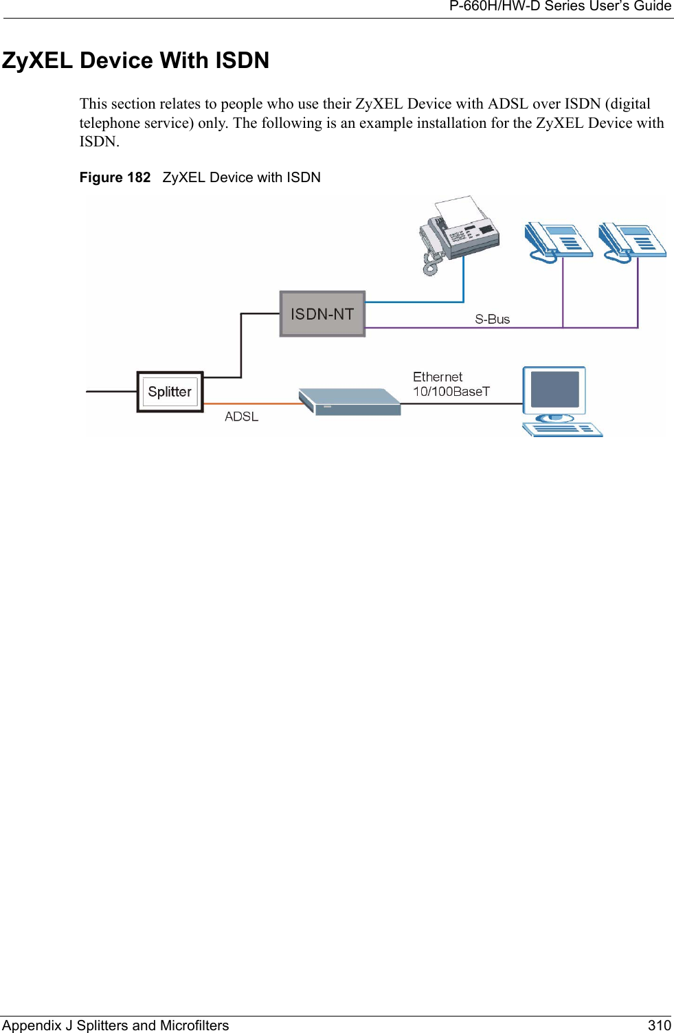
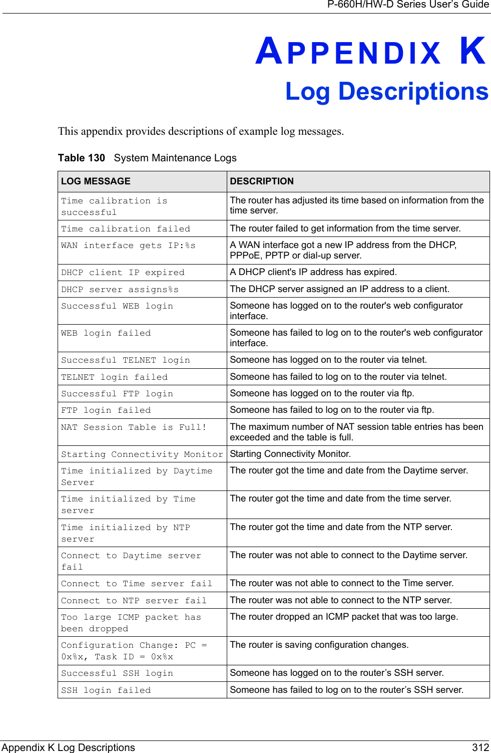
ZyXEL Communications P660HWD1V2 802.11g WIRELESS ADSL2+ 4-PORT GATEWAY User Manual P 660H HW W T Series V3 40 User s Guide
ZyXEL Communications Corporation 802.11g WIRELESS ADSL2+ 4-PORT GATEWAY P 660H HW W T Series V3 40 User s Guide
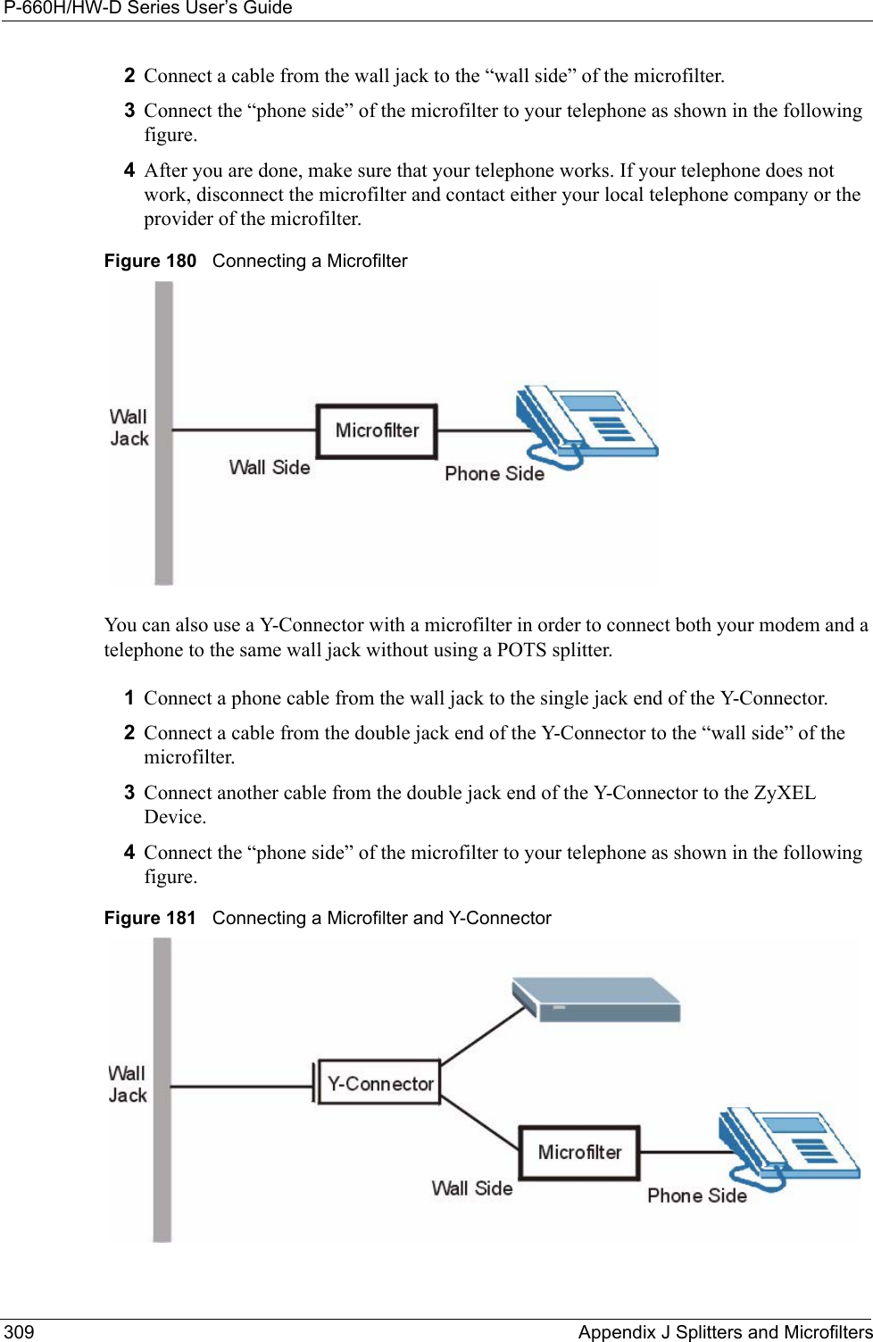
Contents
users manual 6
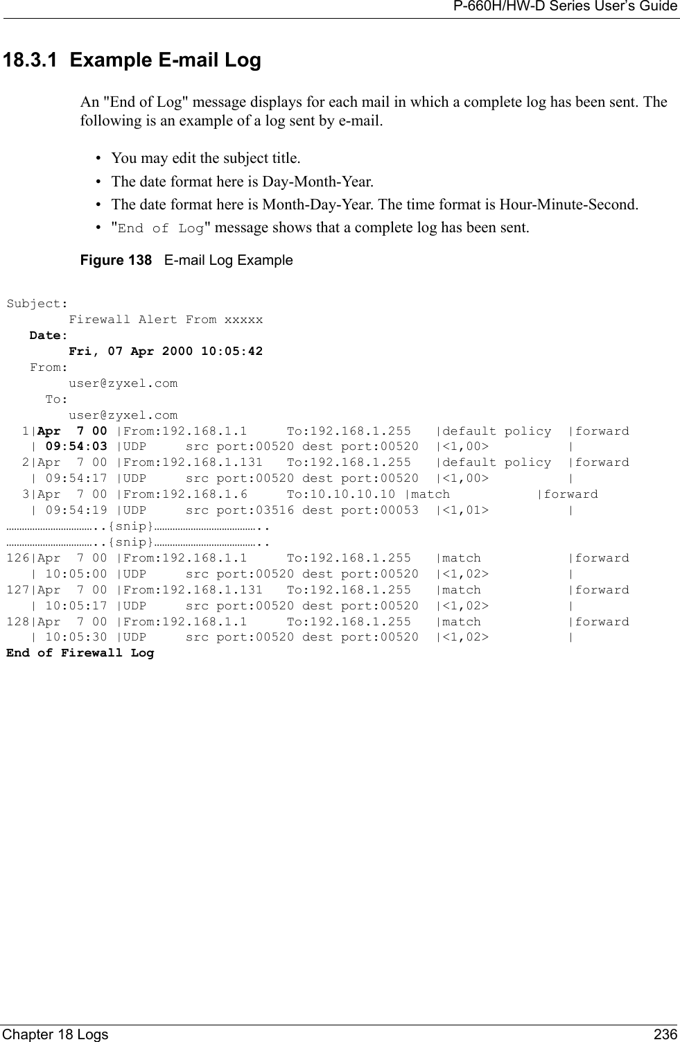

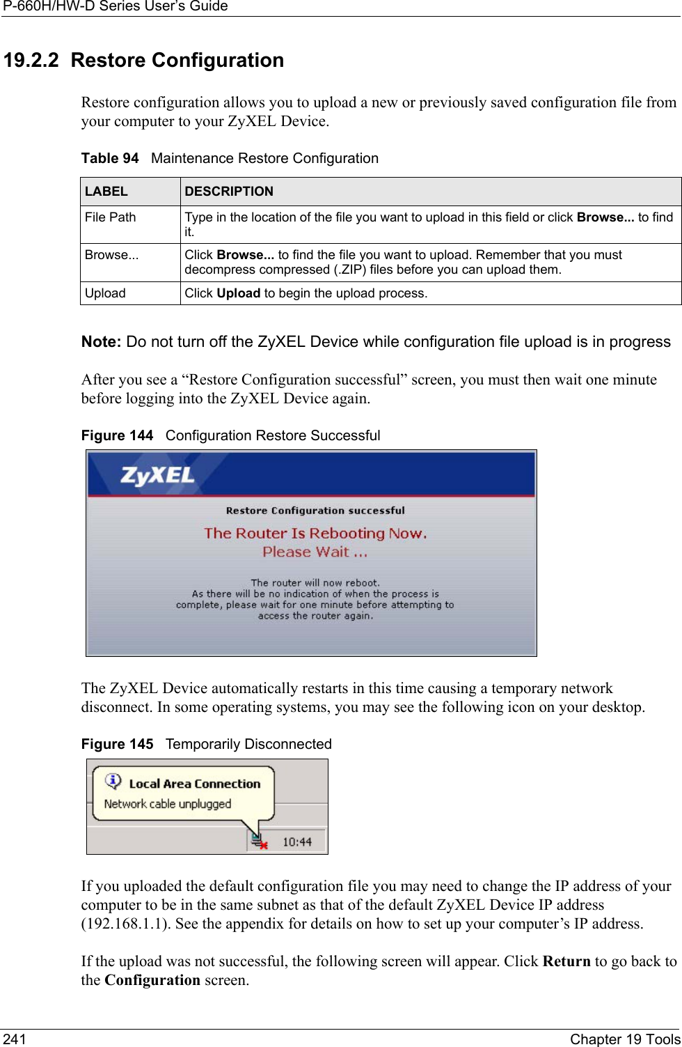

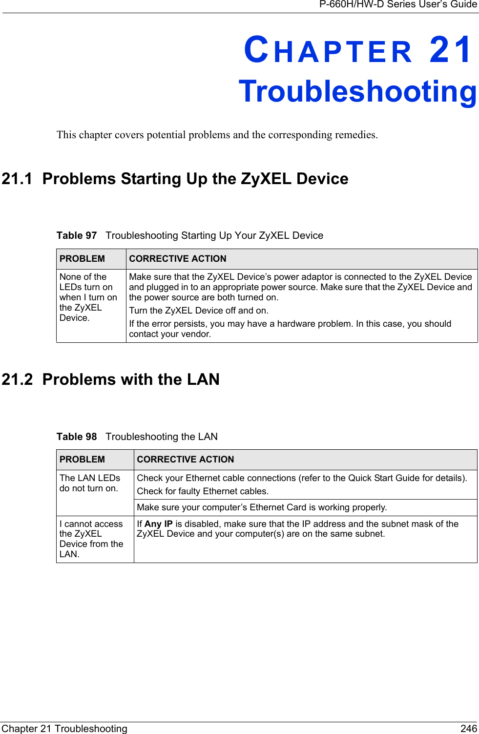


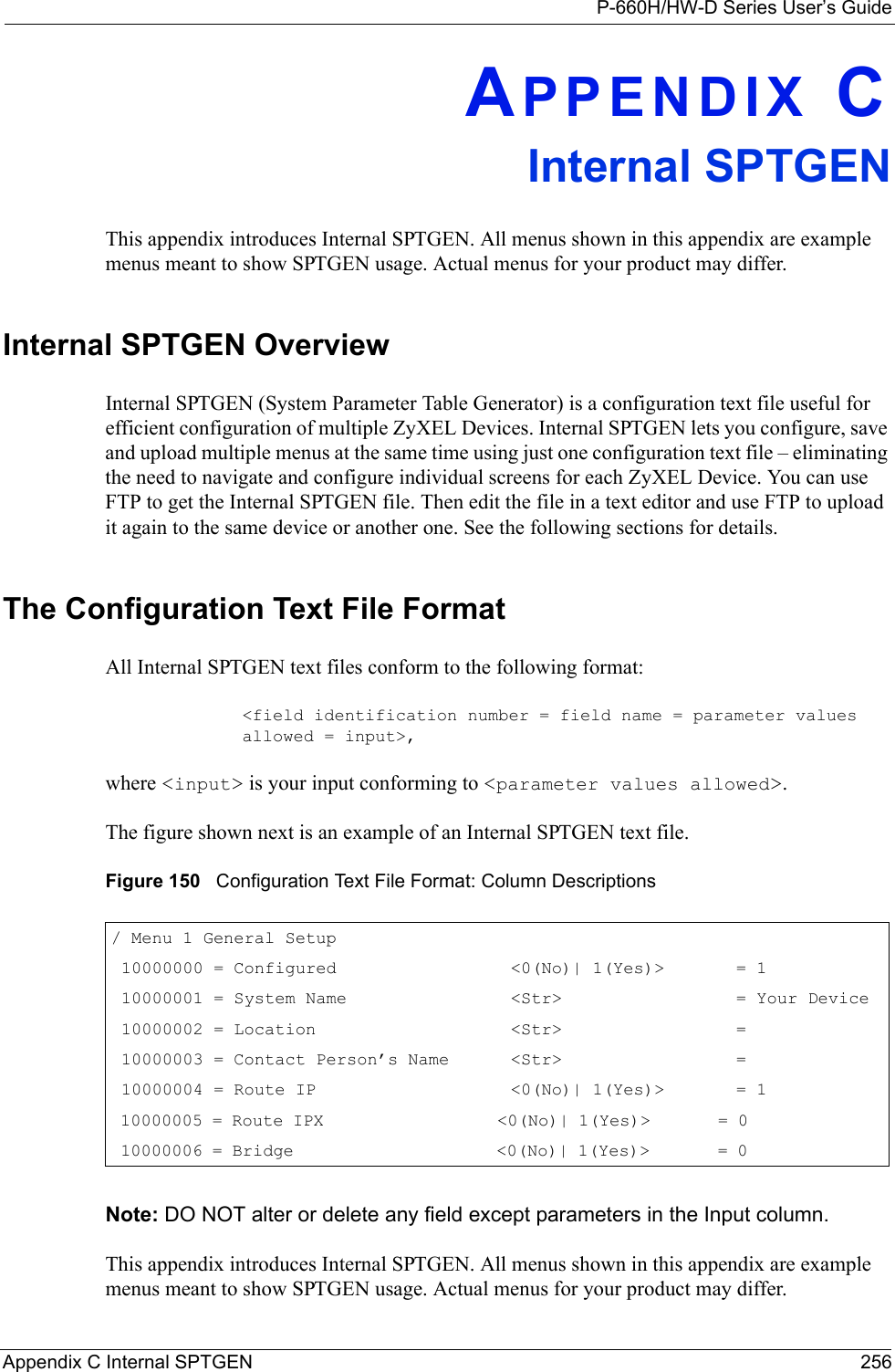
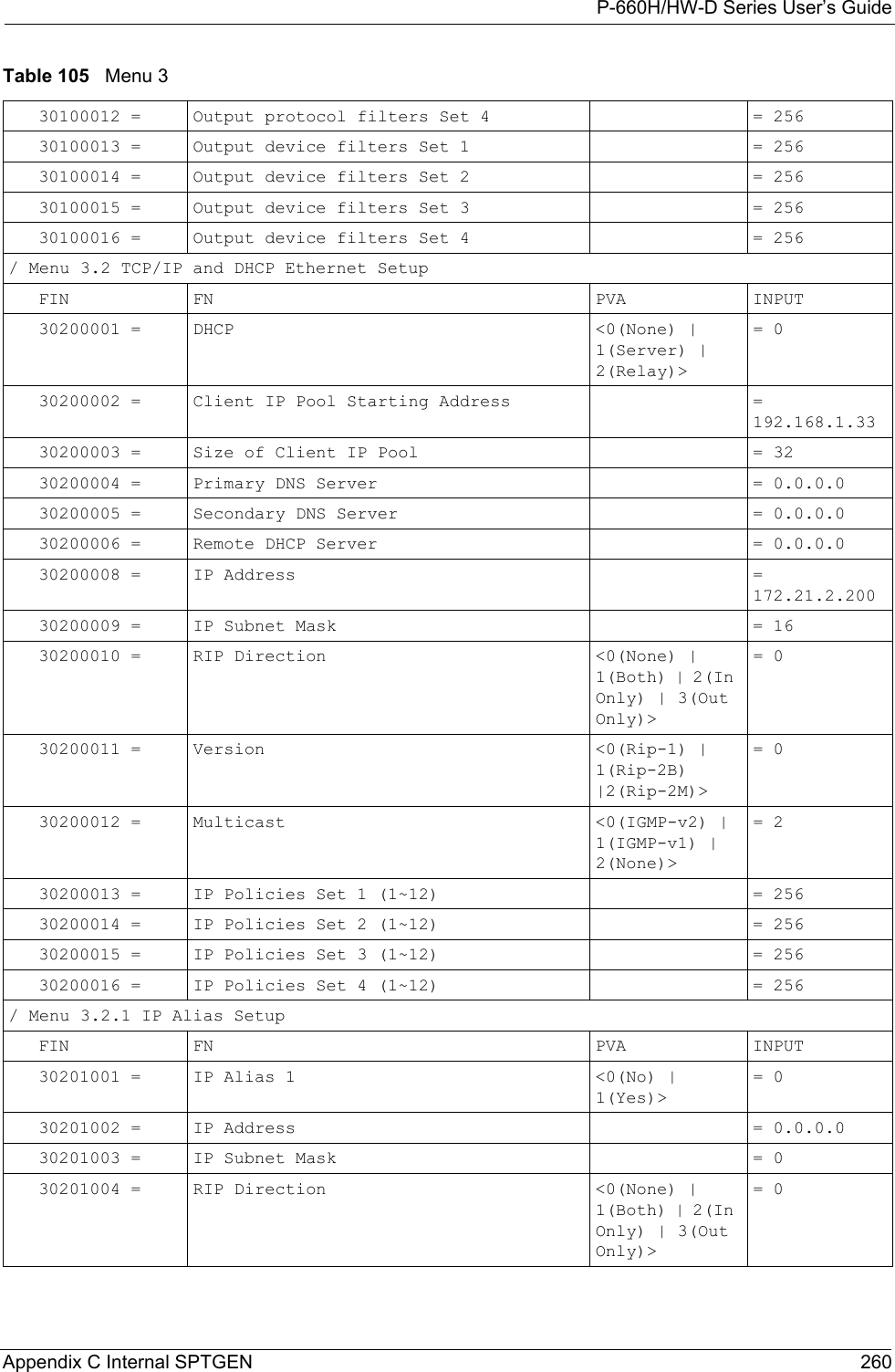
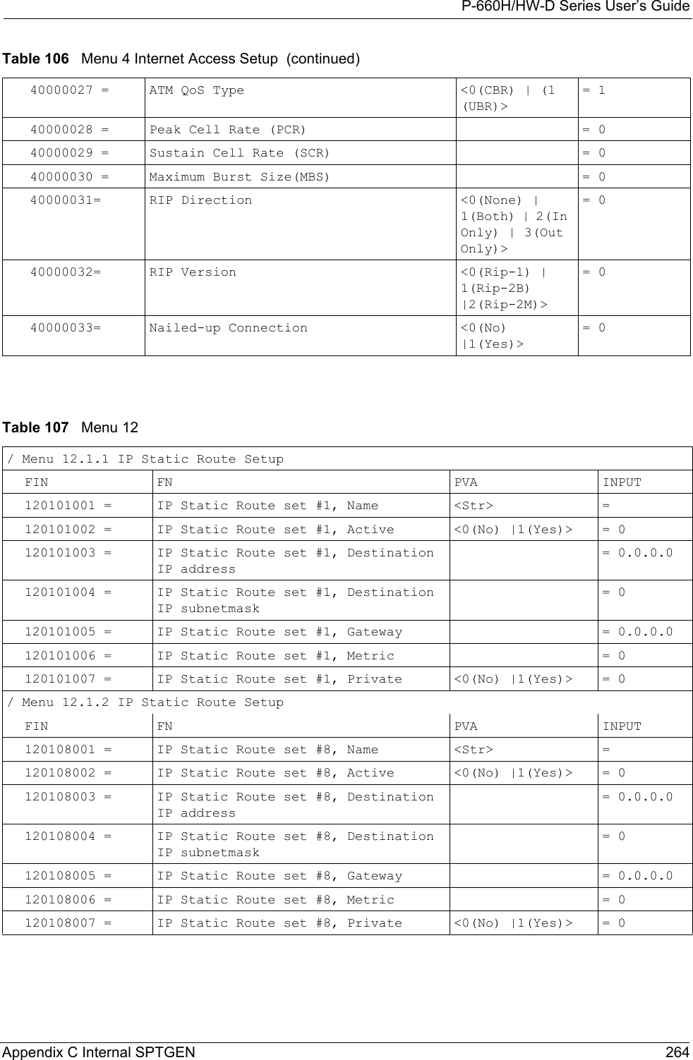
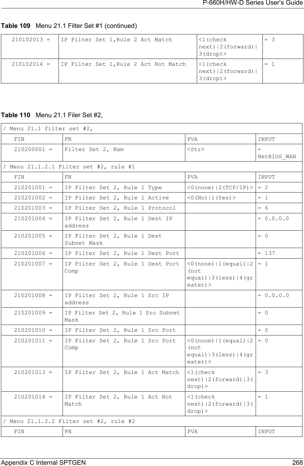
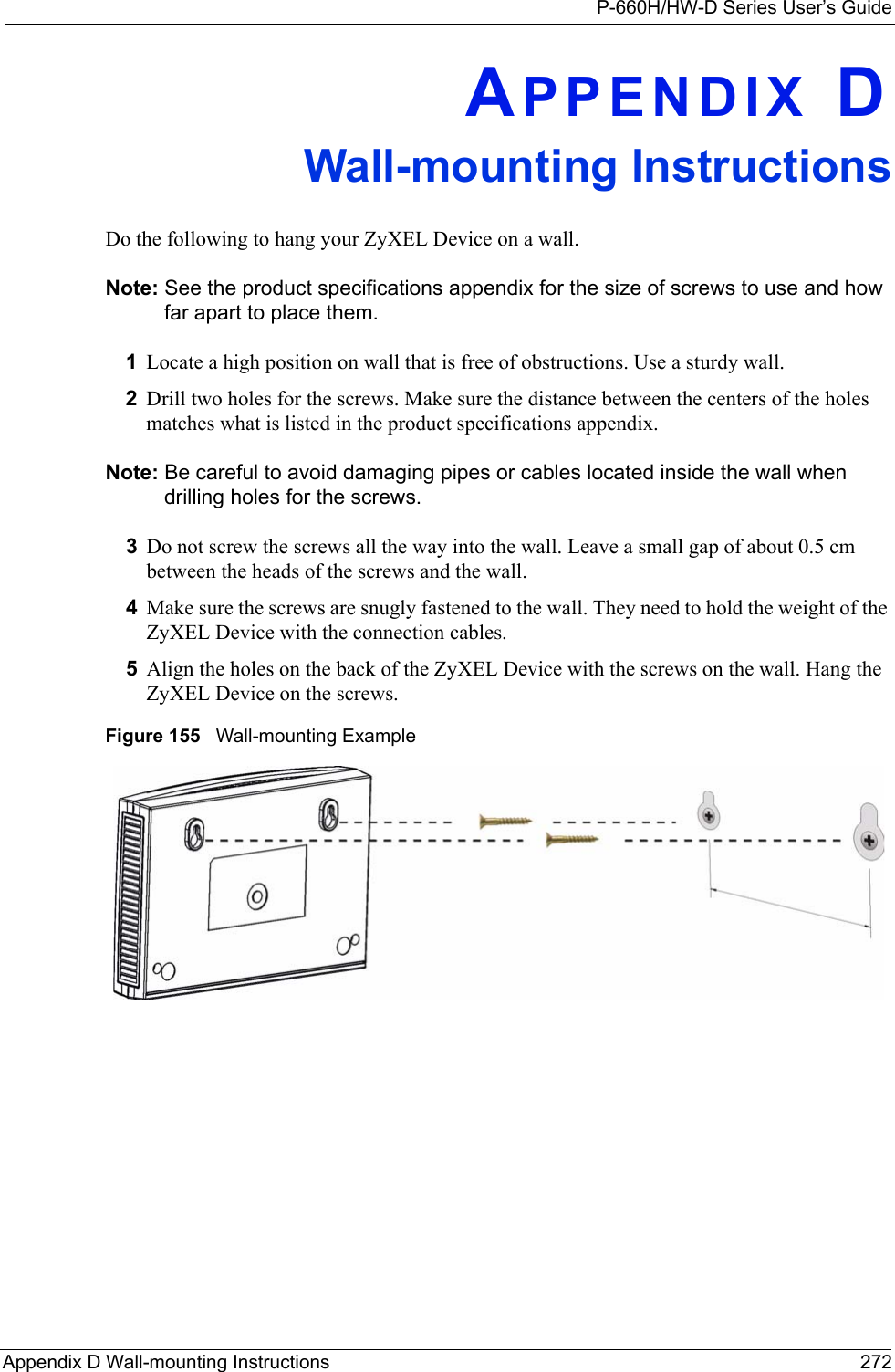

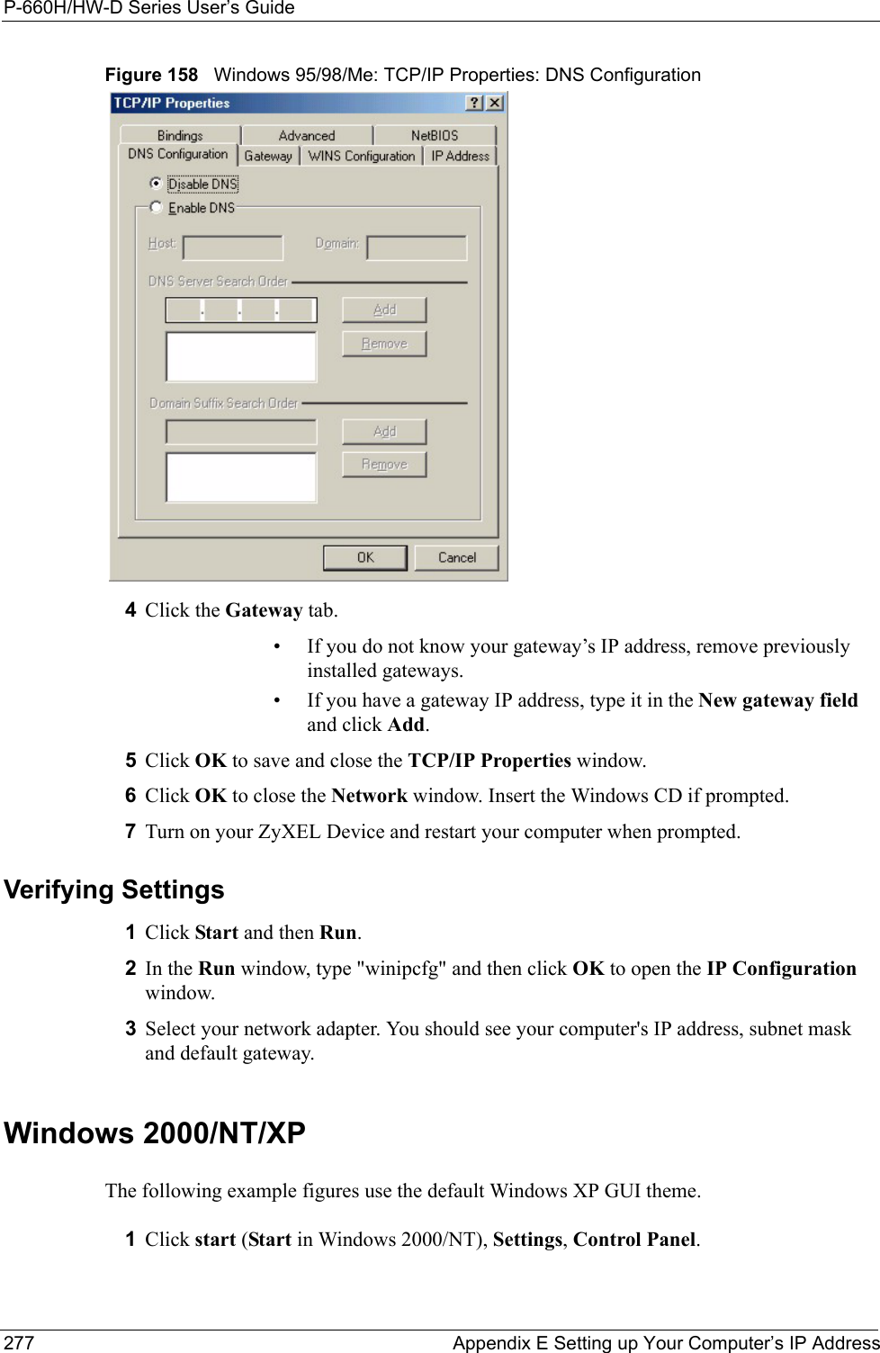
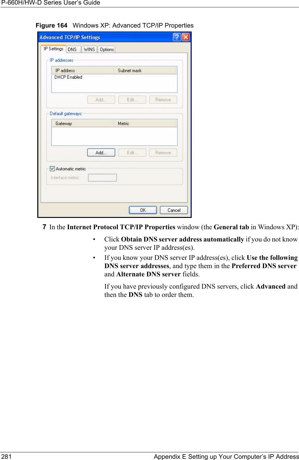
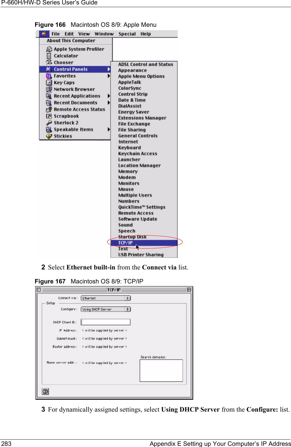
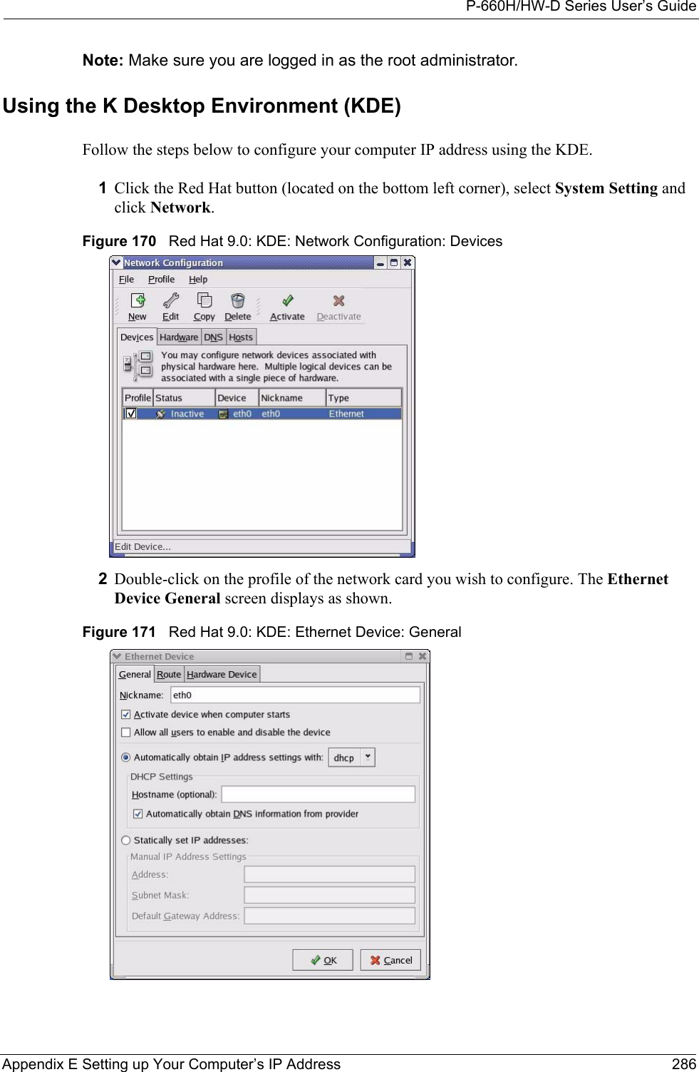
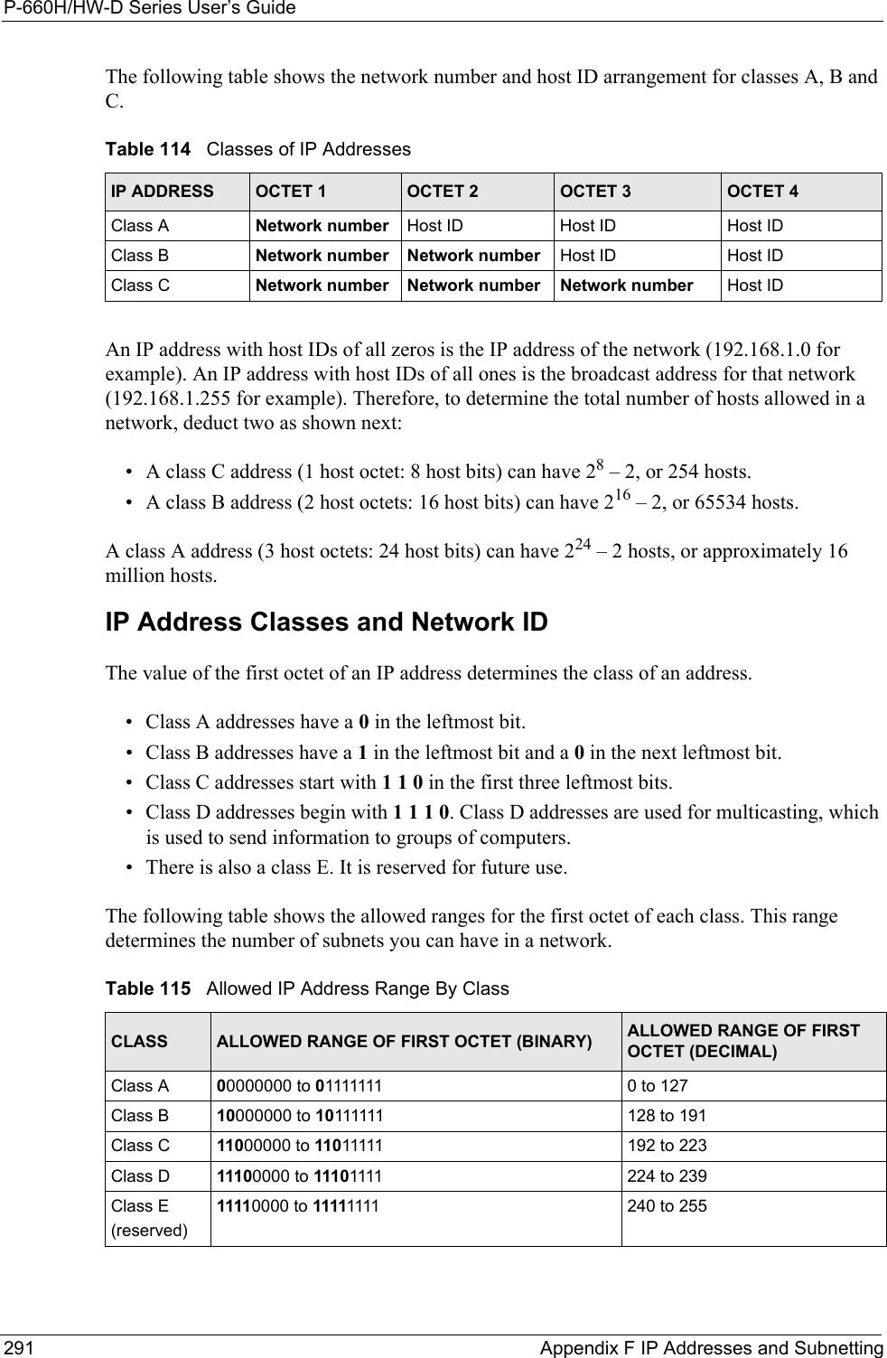
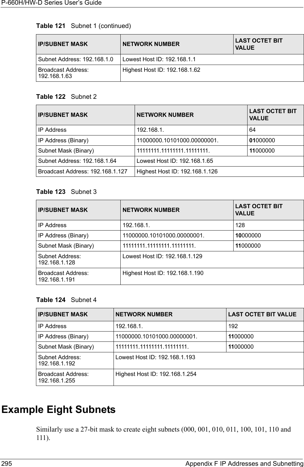
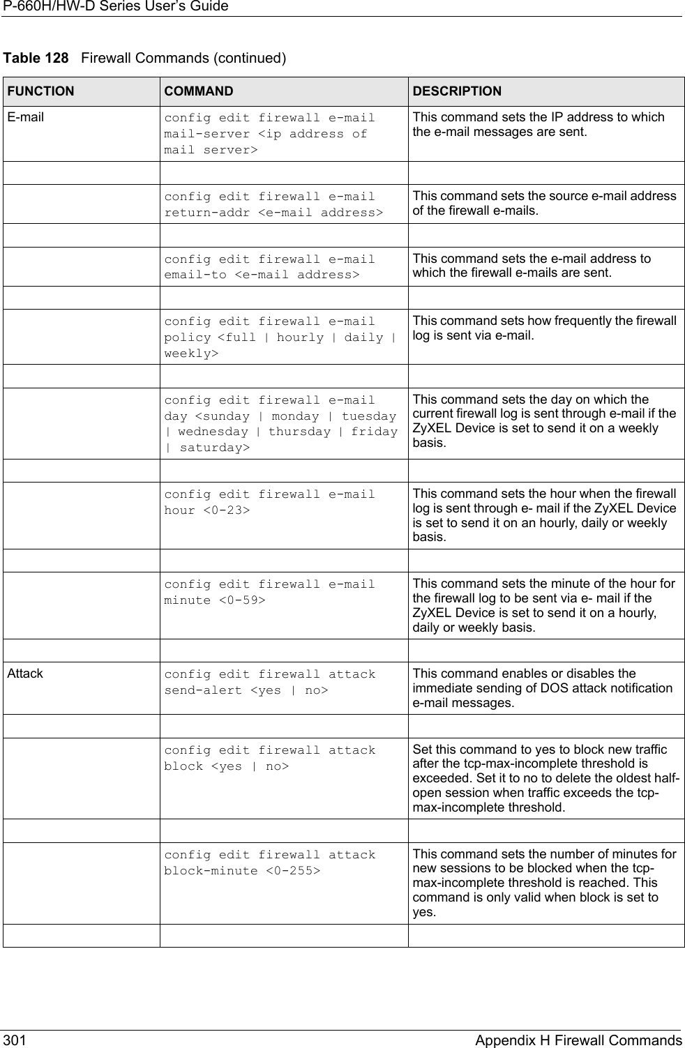
![P-660H/HW-D Series User’s GuideAppendix E Setting up Your Computer’s IP Address 282Figure 165 Windows XP: Internet Protocol (TCP/IP) Properties8Click OK to close the Internet Protocol (TCP/IP) Properties window.9Click Close (OK in Windows 2000/NT) to close the Local Area Connection Properties window.10 Close the Network Connections window (Network and Dial-up Connections in Windows 2000/NT).11Turn on your ZyXEL Device and restart your computer (if prompted).Verifying Settings1Click Start, All Programs, Accessories and then Command Prompt.2In the Command Prompt window, type "ipconfig" and then press [ENTER]. You can also open Network Connections, right-click a network connection, click Status and then click the Support tab.Macintosh OS 8/9 1Click the Apple menu, Control Panel and double-click TCP/IP to open the TCP/IP Control Panel.](https://usermanual.wiki/ZyXEL-Communications/P660HWD1V2.users-manual-6/User-Guide-717832-Page-47.png)
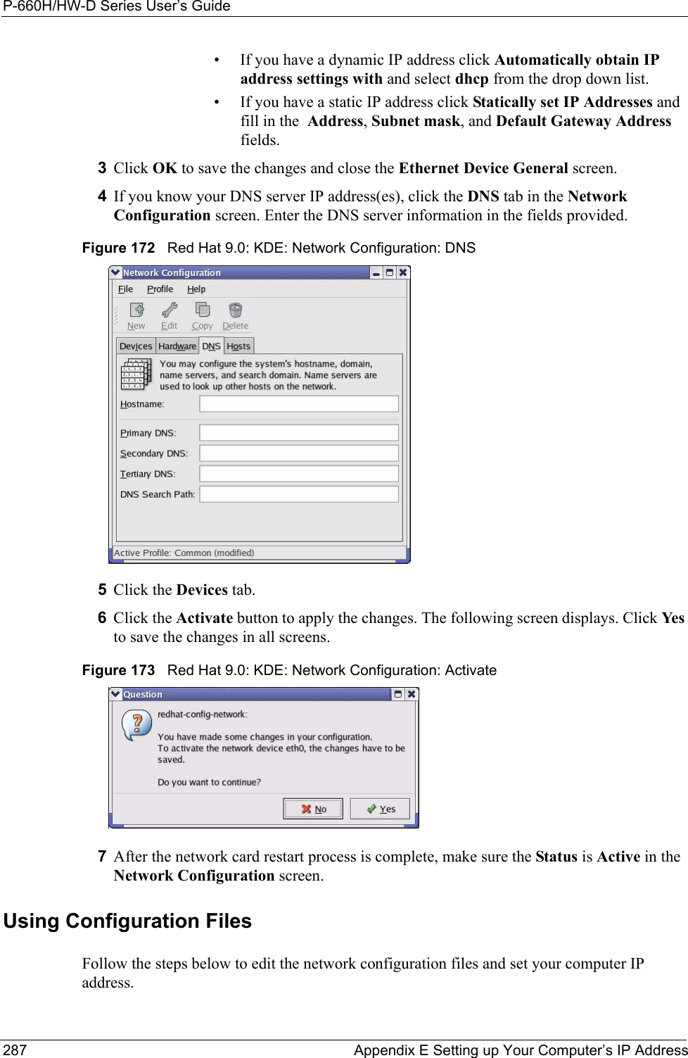
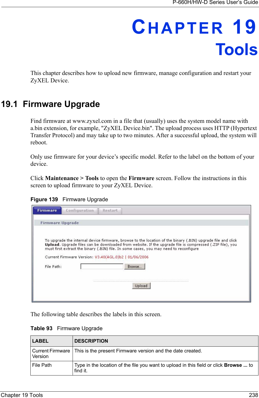
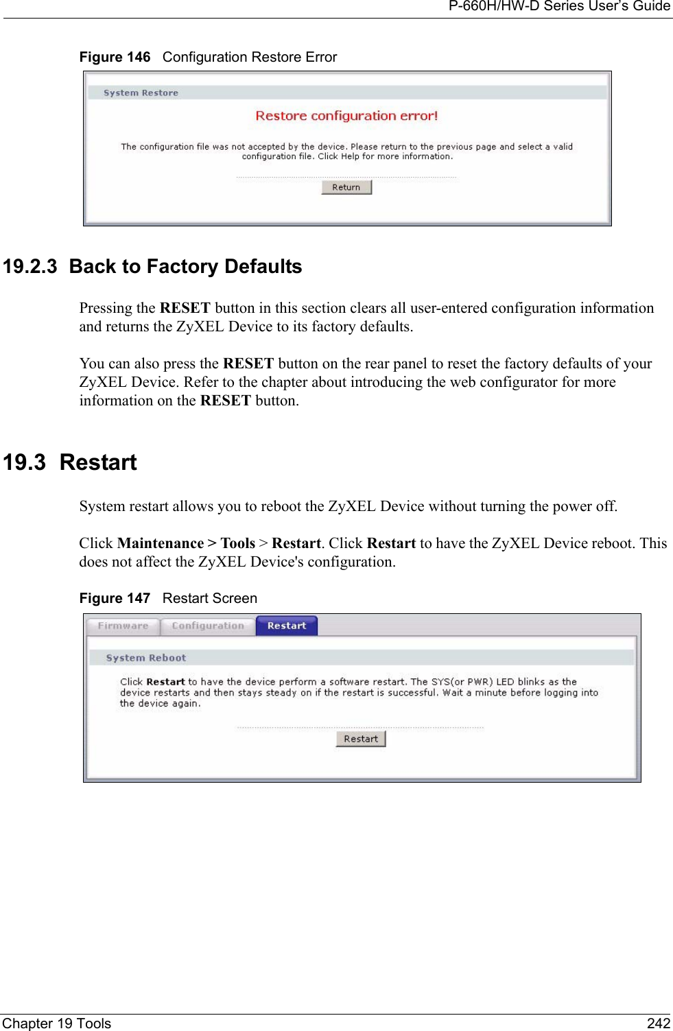
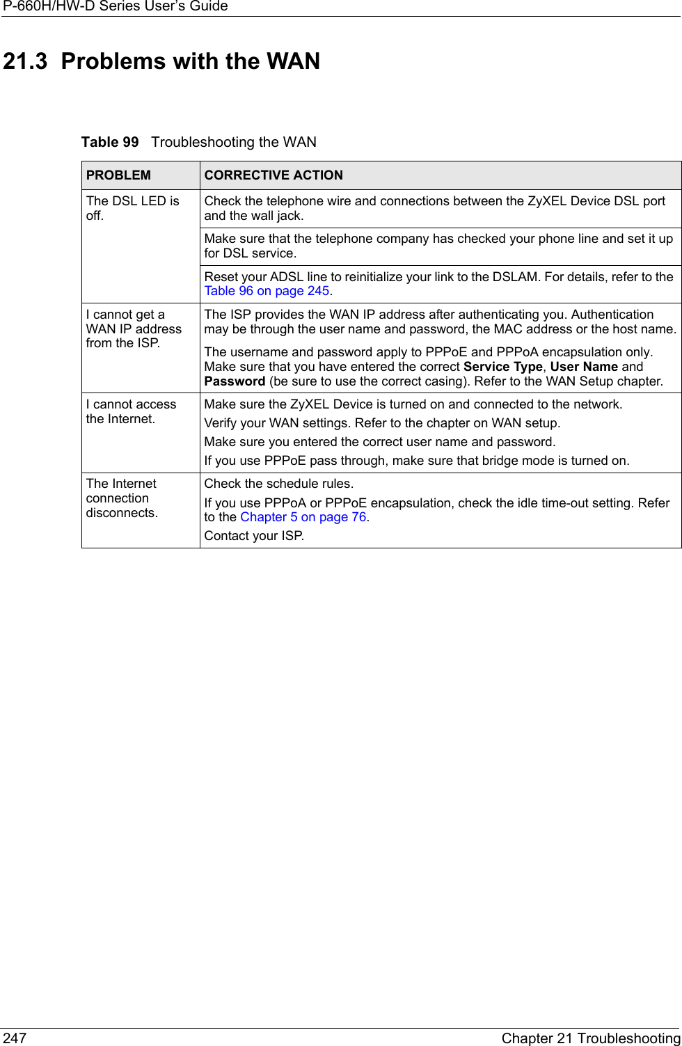
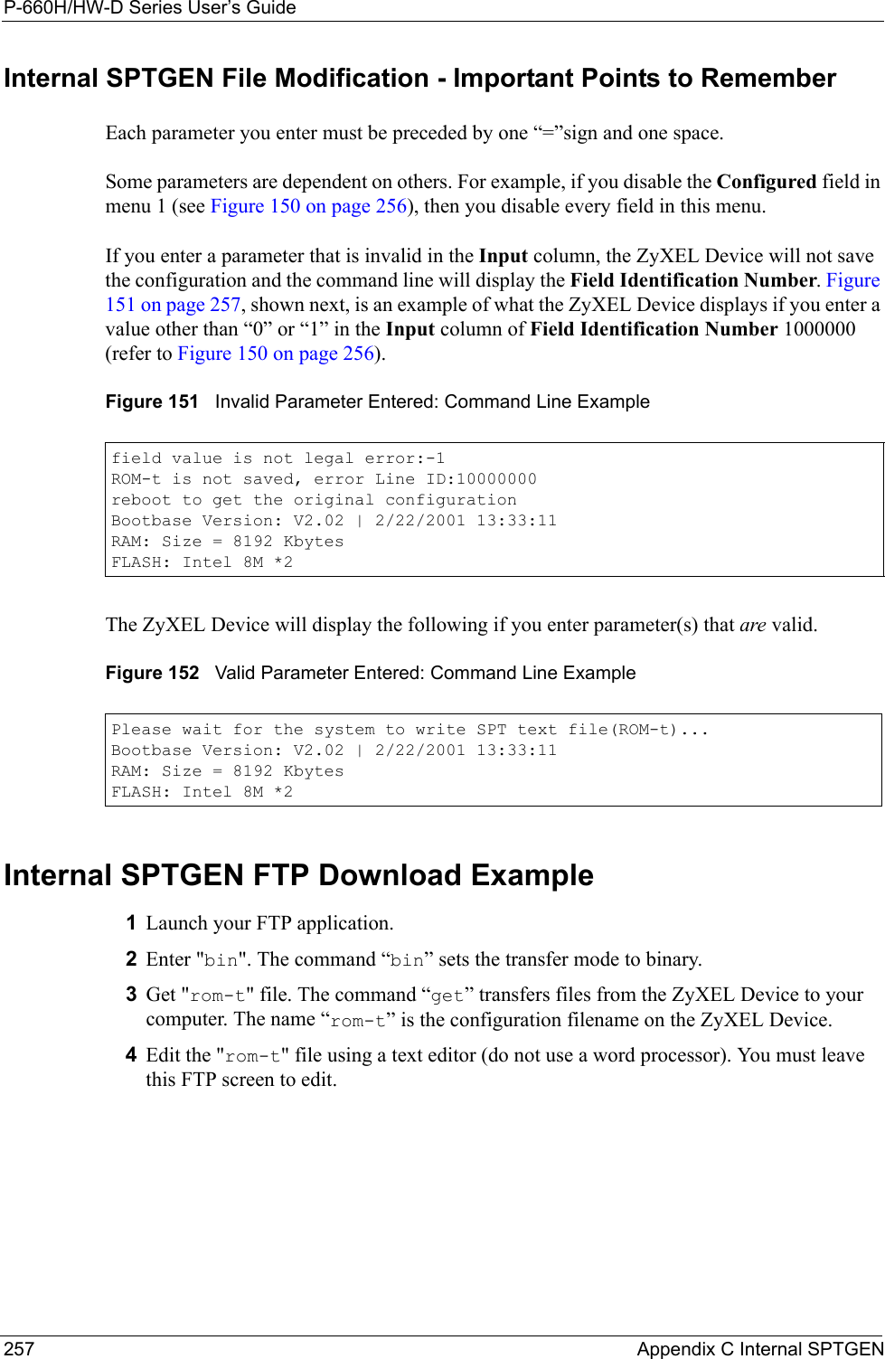
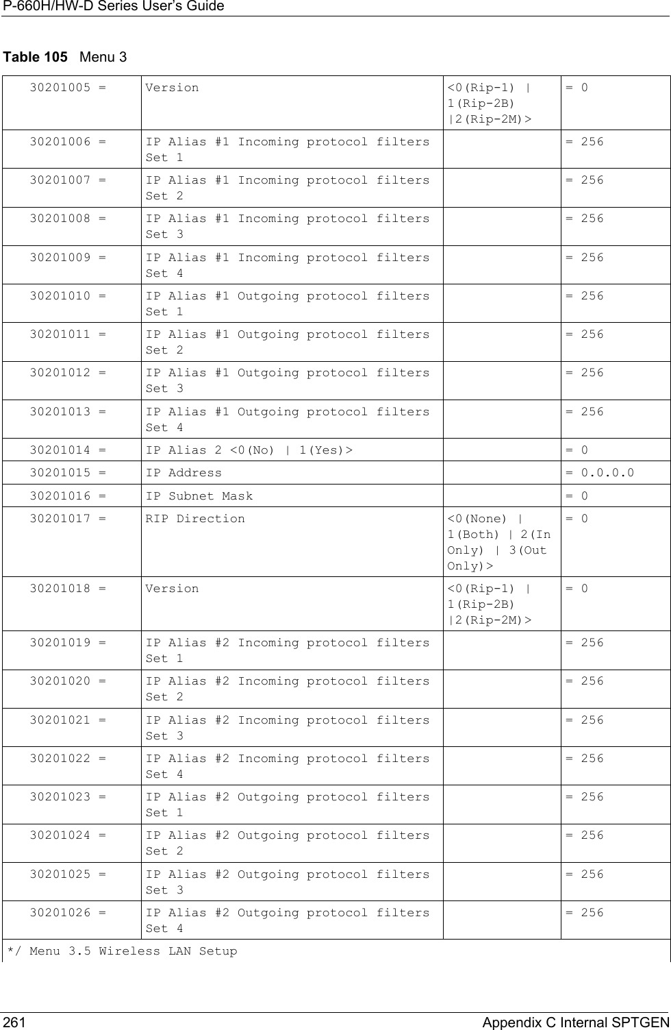
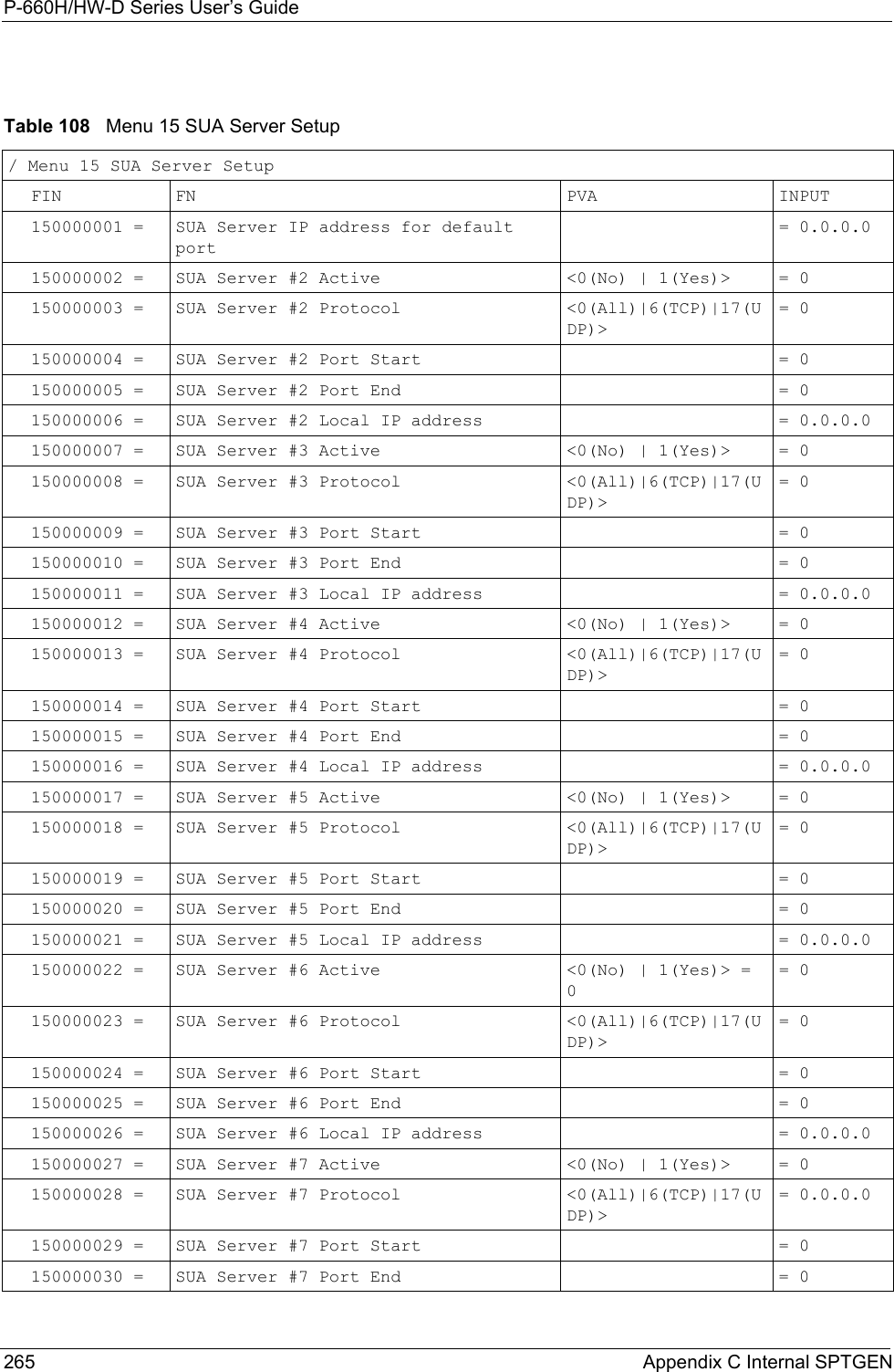
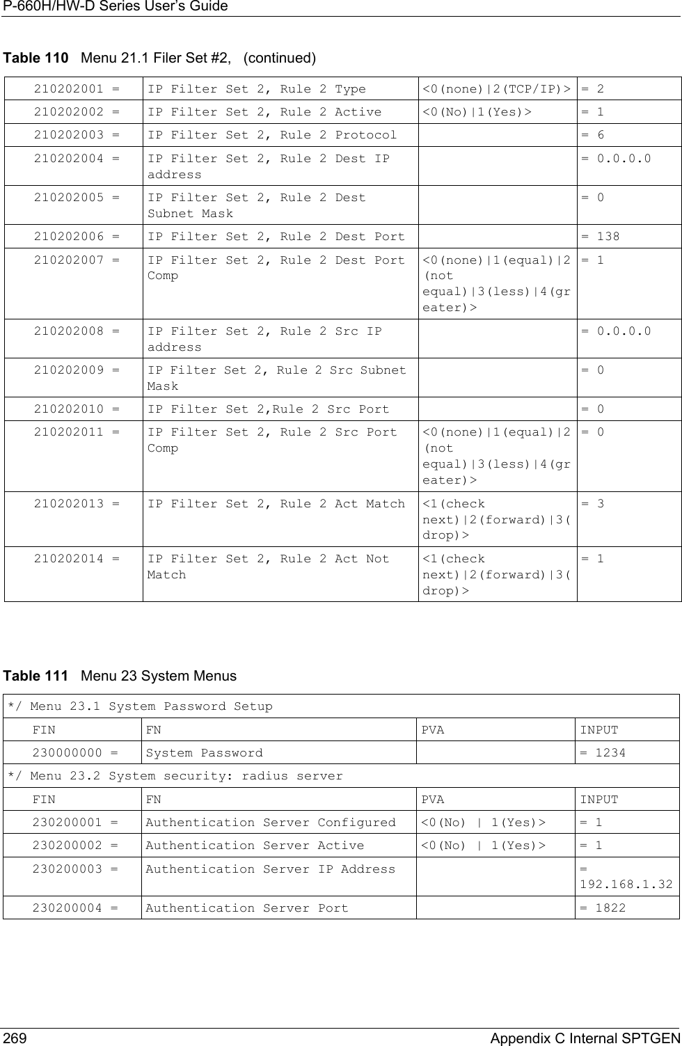
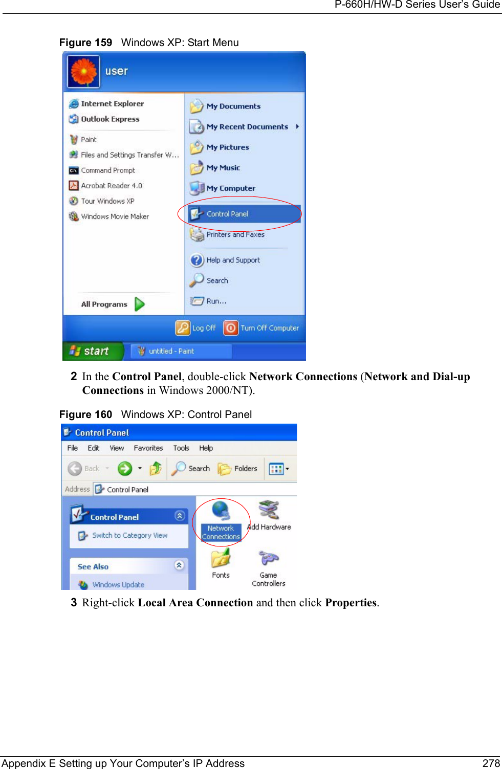
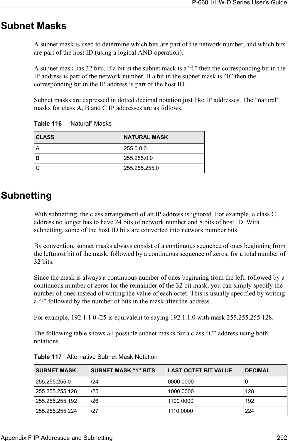
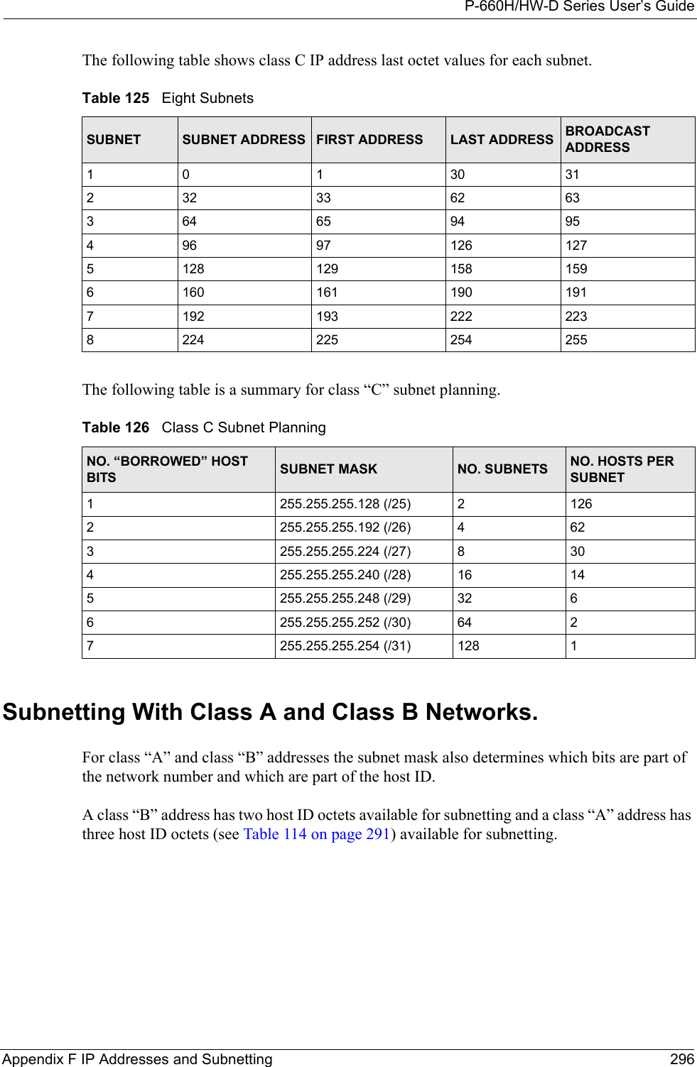
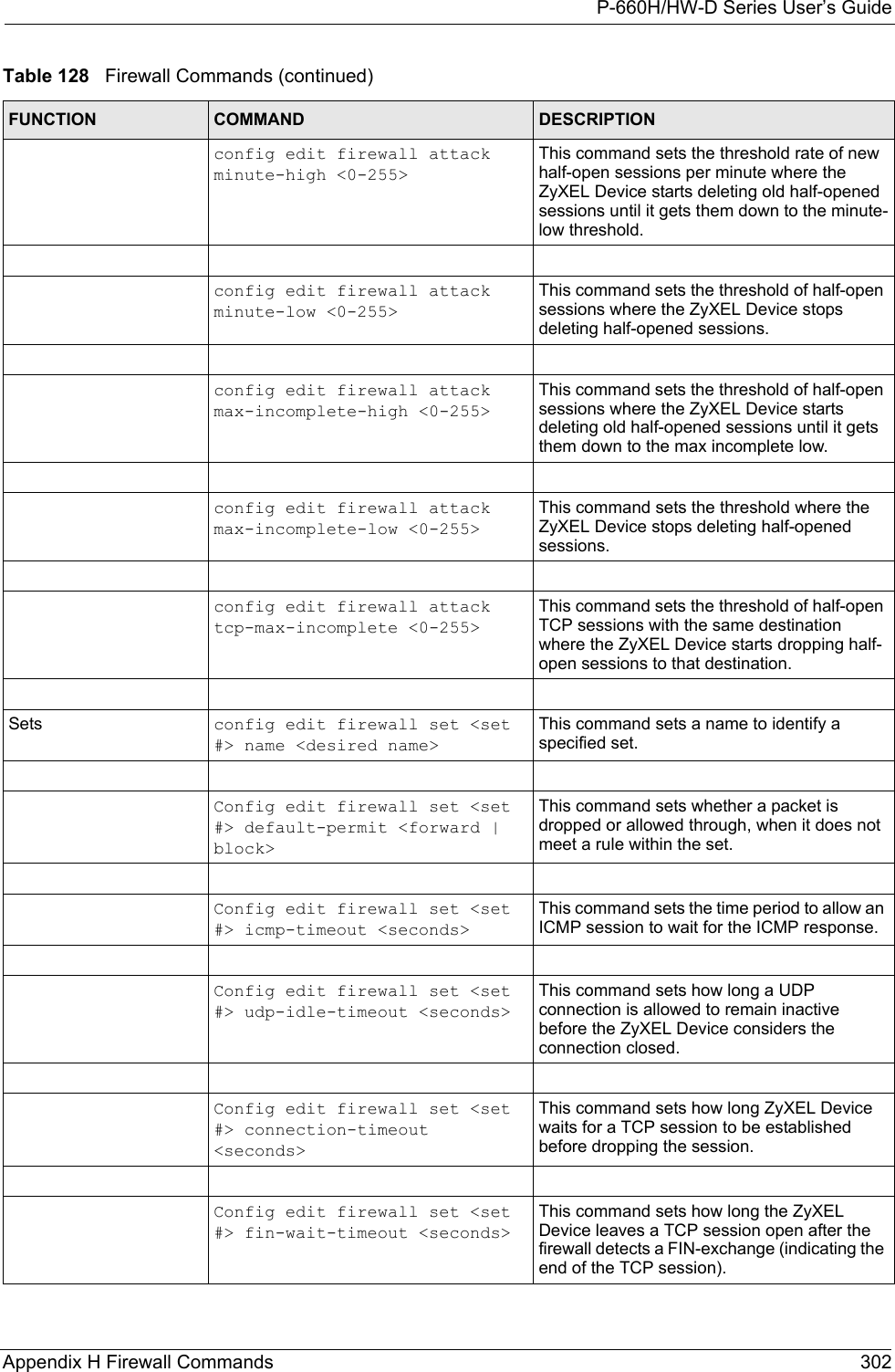
![P-660H/HW-D Series User’s Guide289 Appendix E Setting up Your Computer’s IP AddressFigure 177 Red Hat 9.0: Restart Ethernet Card 21.4.1 Verifying SettingsEnter ifconfig in a terminal screen to check your TCP/IP properties. Figure 178 Red Hat 9.0: Checking TCP/IP Properties [root@localhost init.d]# network restartShutting down interface eth0: [OK]Shutting down loopback interface: [OK]Setting network parameters: [OK]Bringing up loopback interface: [OK]Bringing up interface eth0: [OK][root@localhost]# ifconfig eth0 Link encap:Ethernet HWaddr 00:50:BA:72:5B:44 inet addr:172.23.19.129 Bcast:172.23.19.255 Mask:255.255.255.0 UP BROADCAST RUNNING MULTICAST MTU:1500 Metric:1 RX packets:717 errors:0 dropped:0 overruns:0 frame:0 TX packets:13 errors:0 dropped:0 overruns:0 carrier:0 collisions:0 txqueuelen:100 RX bytes:730412 (713.2 Kb) TX bytes:1570 (1.5 Kb) Interrupt:10 Base address:0x1000 [root@localhost]#](https://usermanual.wiki/ZyXEL-Communications/P660HWD1V2.users-manual-6/User-Guide-717832-Page-54.png)
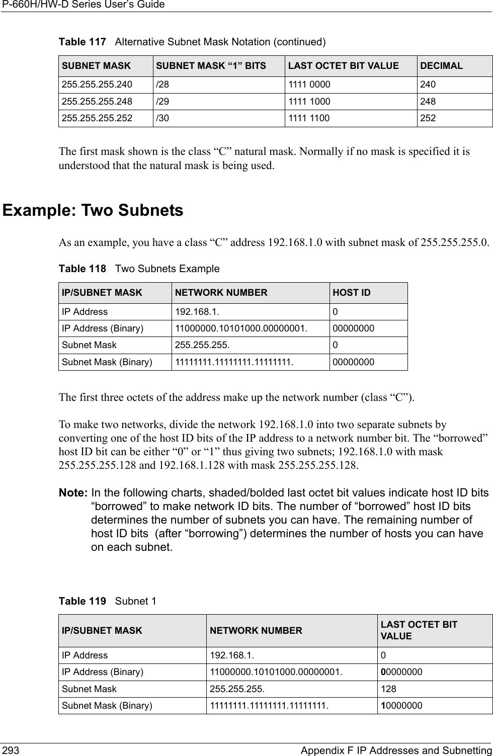
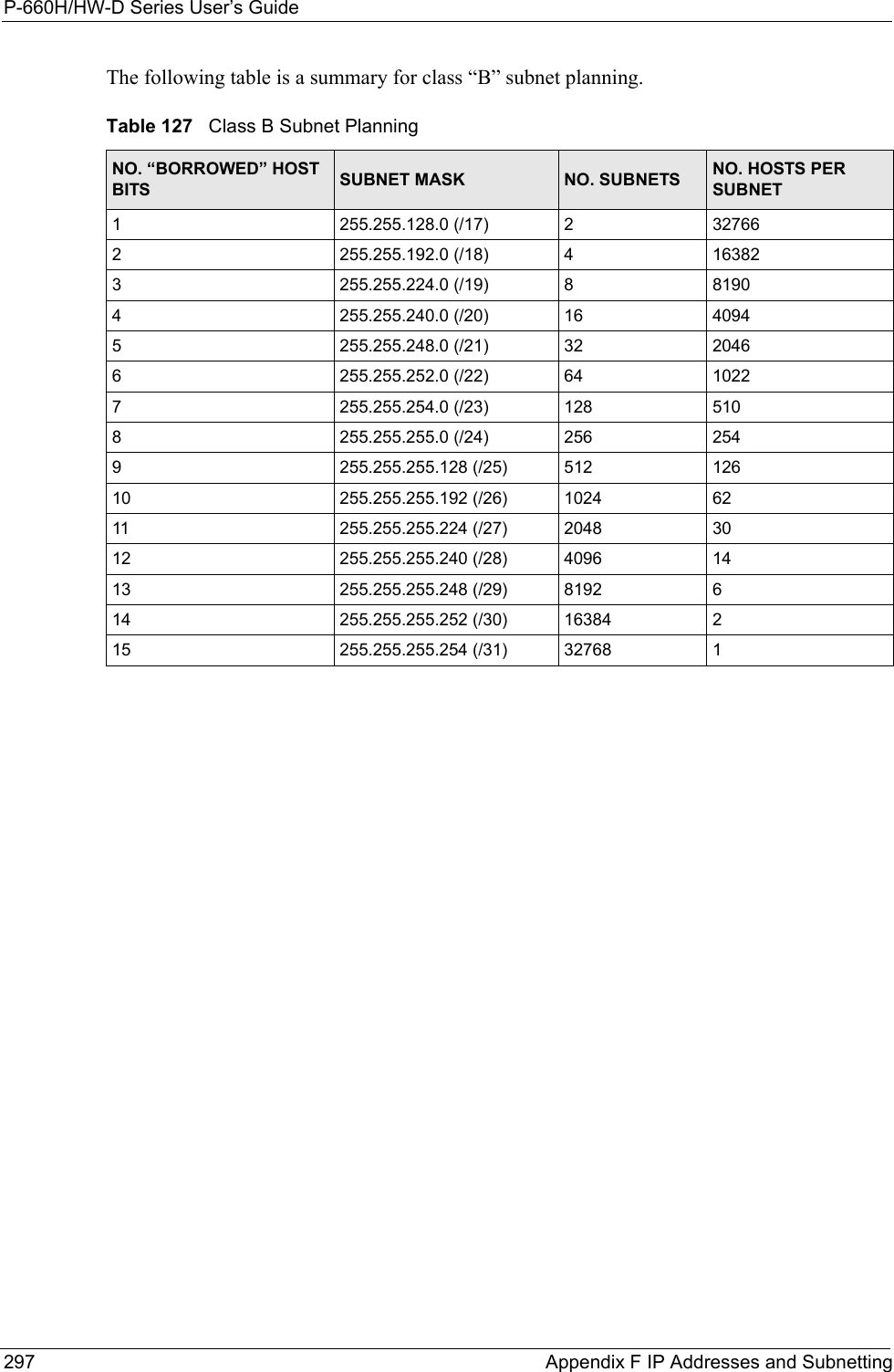
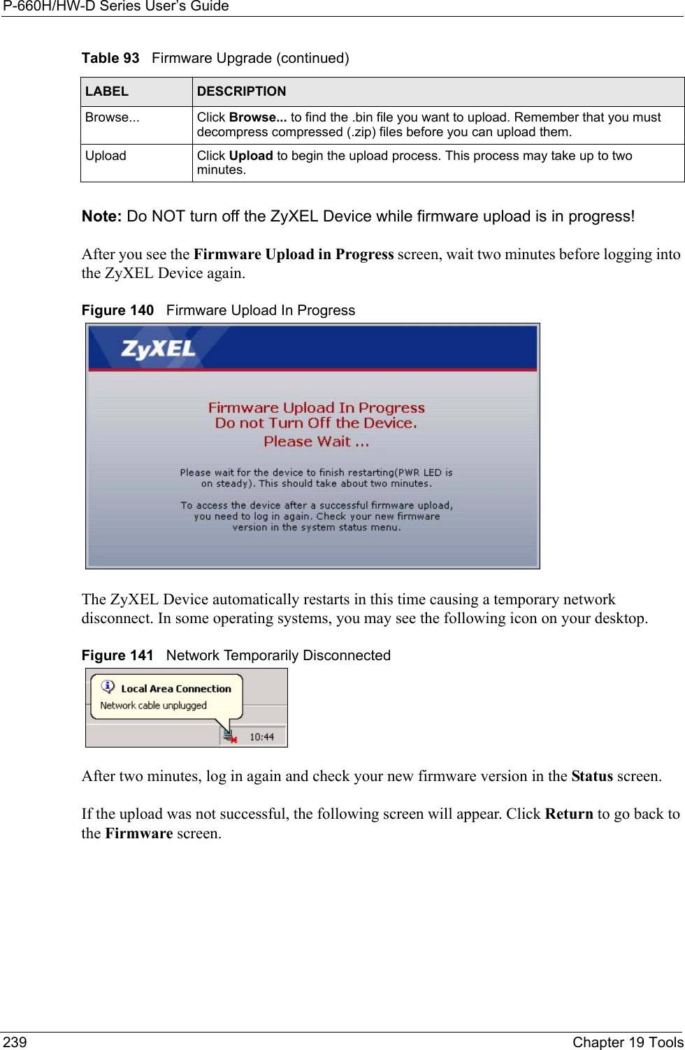
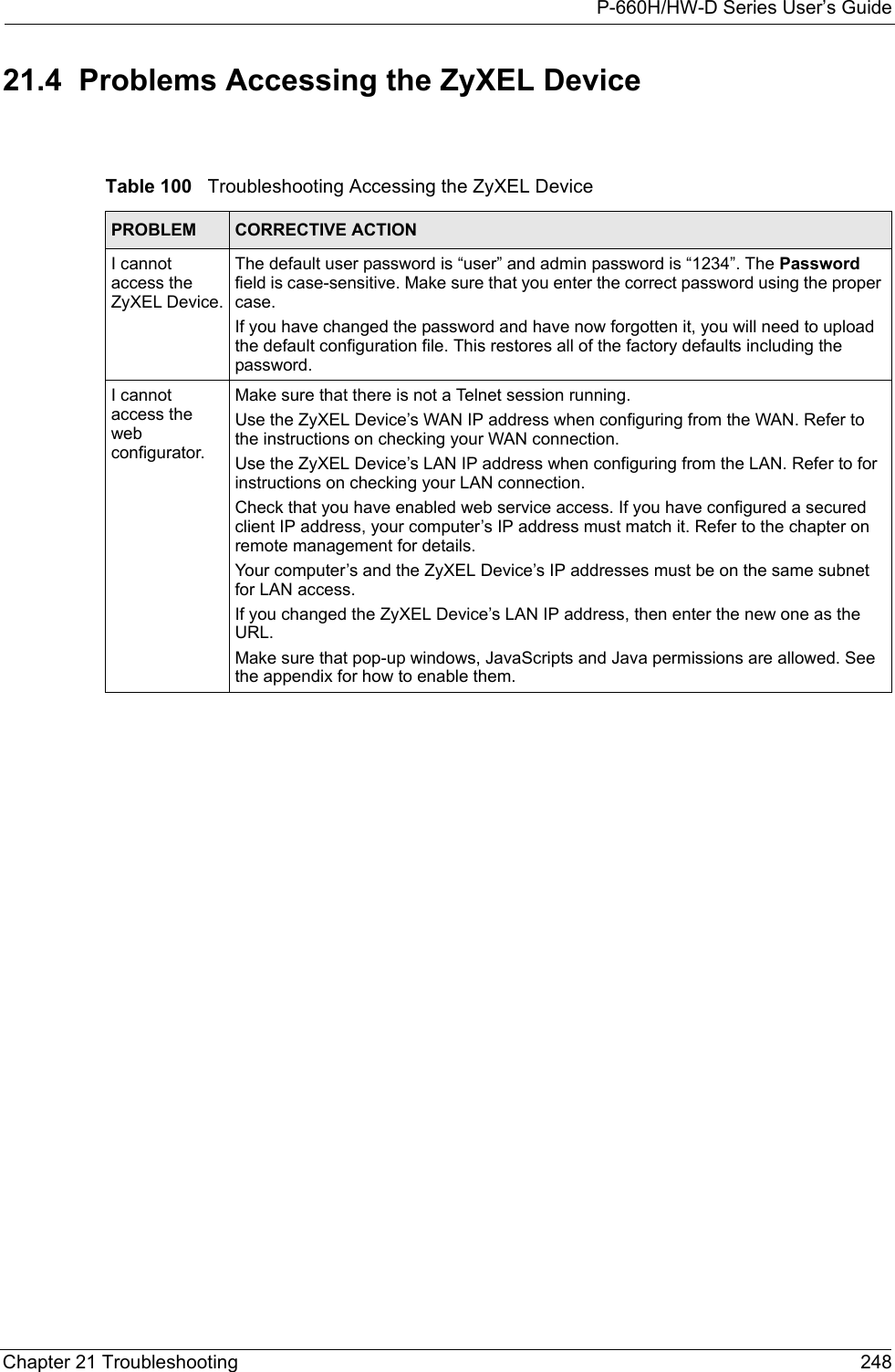
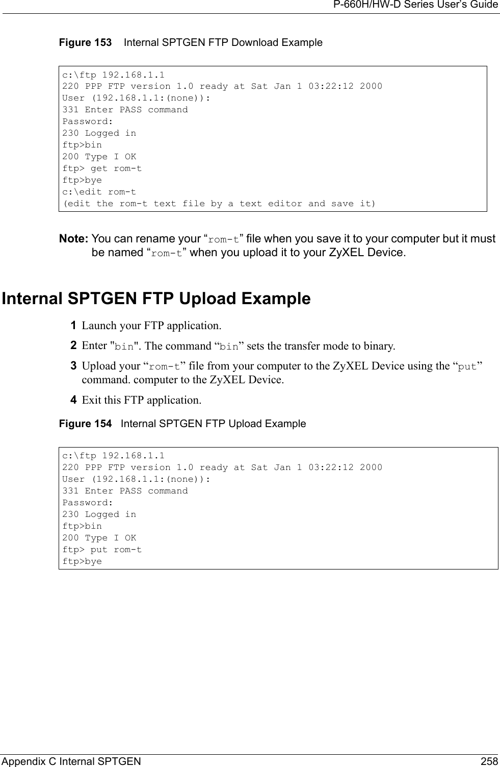
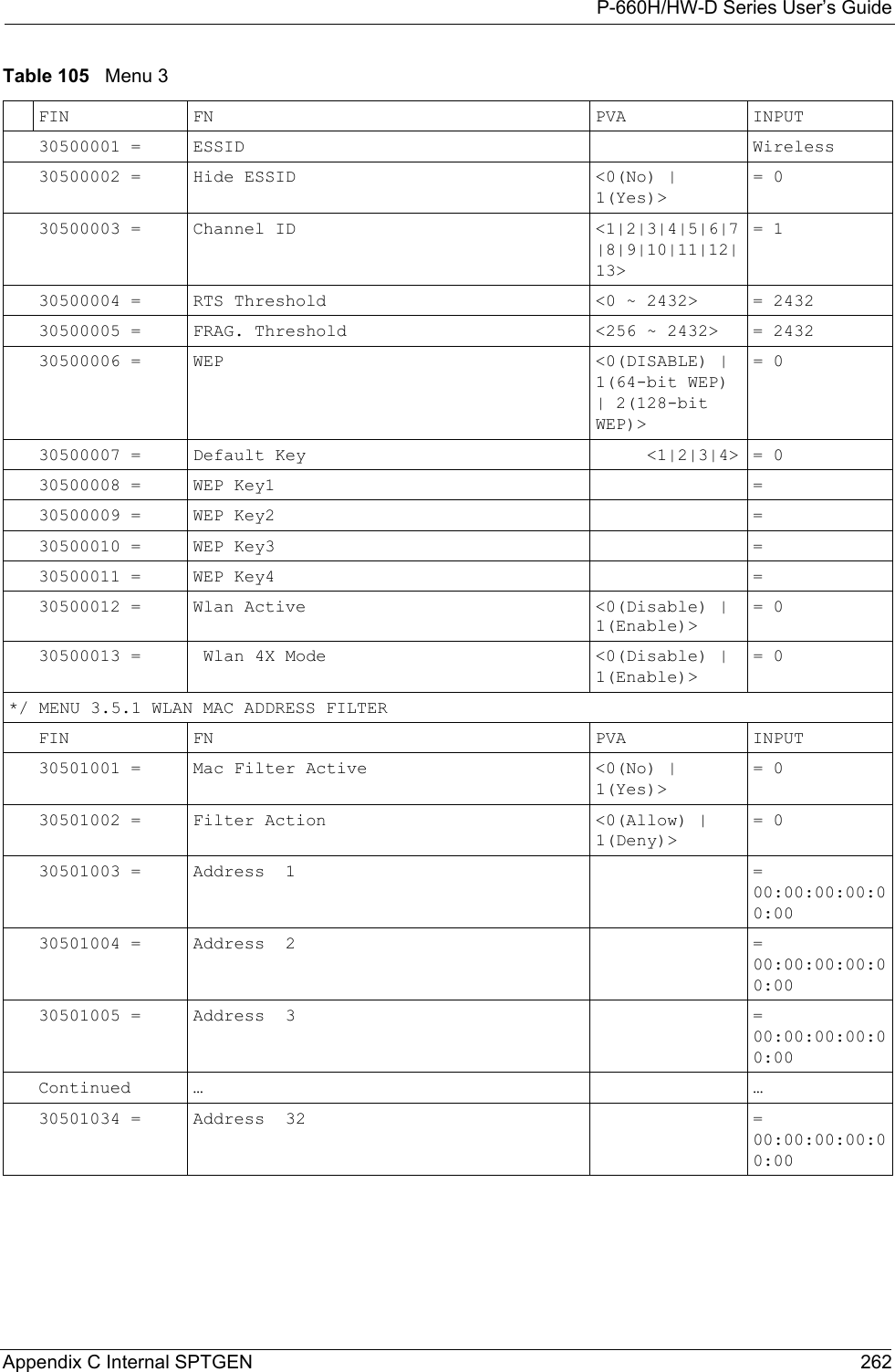
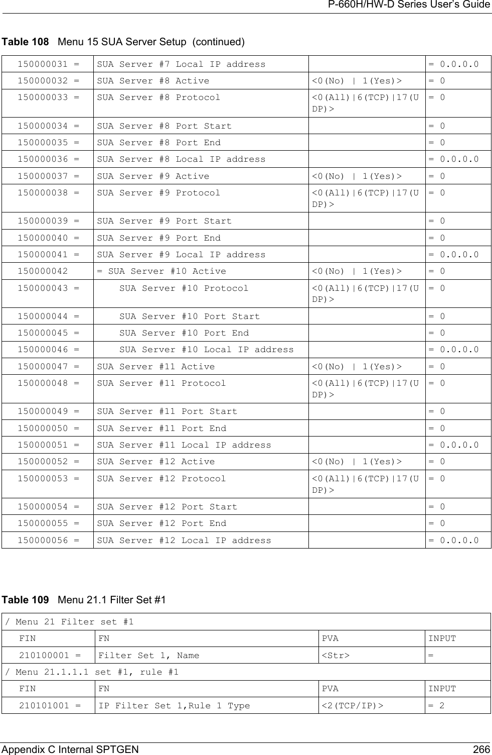
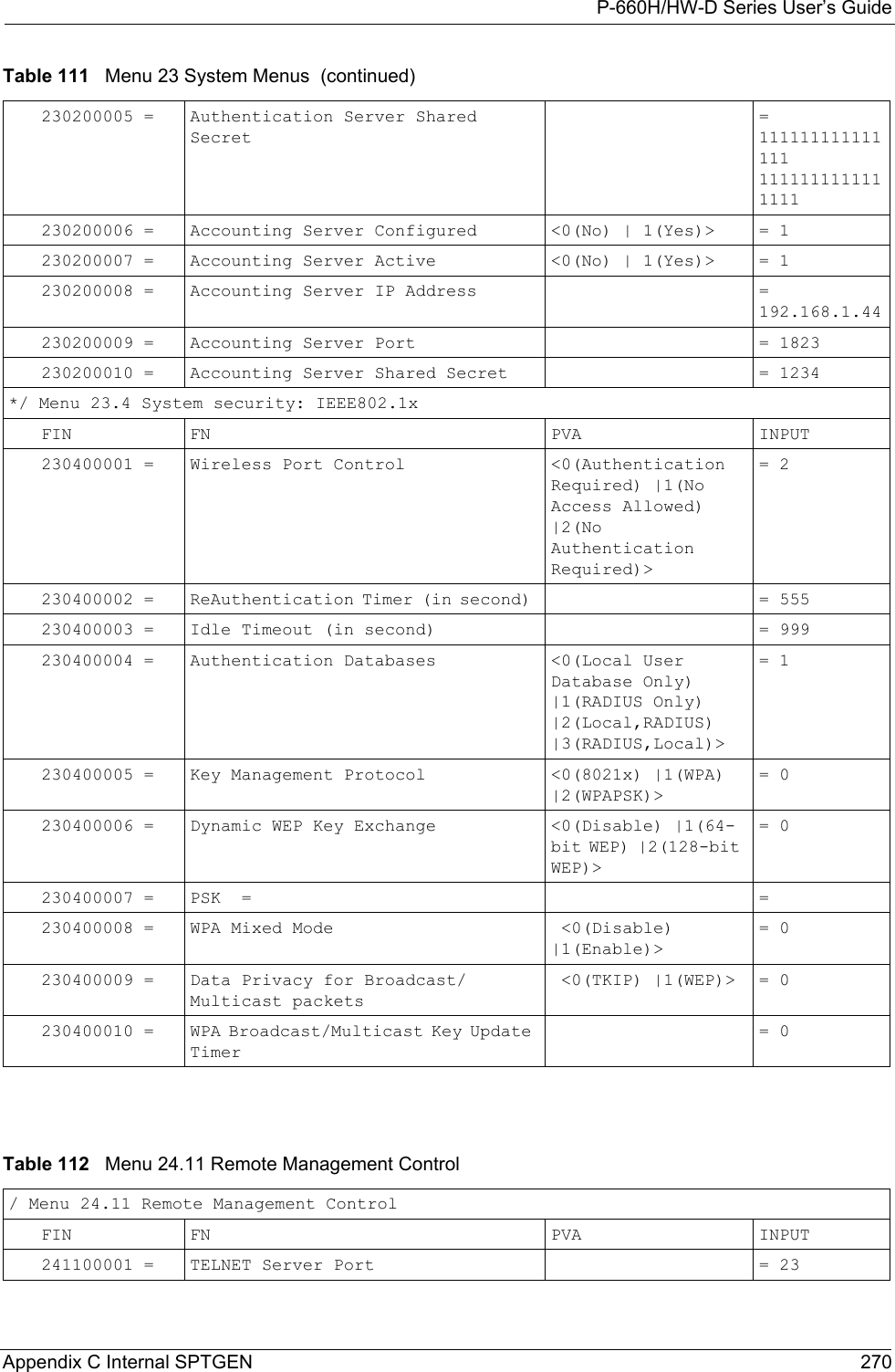
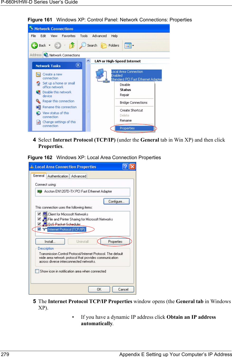
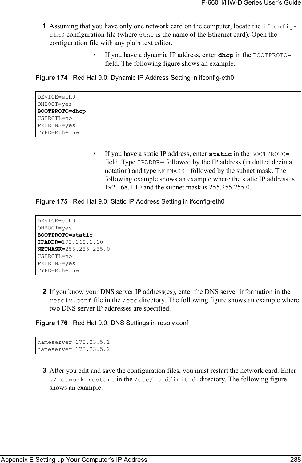
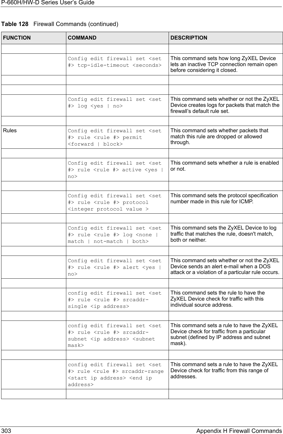
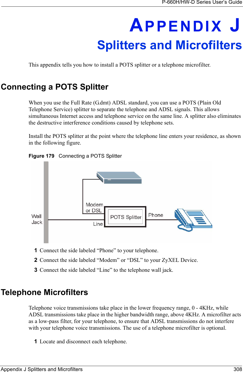
![P-660H/HW-D Series User’s GuideAppendix G Command Interpreter 298APPENDIX GCommand InterpreterThe following describes how to use the command interpreter. You can telnet to access the CLI (Command Line Interface) on the ZyXEL Device. See the included disk or zyxel.com for more detailed information on these commands.Note: Use of undocumented commands or misconfiguration can damage the unit and possibly render it unusable.Accessing the CLIUse the following steps to telnet into your ZyXEL Device.1Connect your computer to the ETHERNET port on the ZyXEL Device.2Make sure your computer IP address and the ZyXEL Device IP address are on the same subnet. In Windows, click Start (usually in the bottom left corner), Run and then type telnet 192.168.1.1 (the default ZyXEL Device IP address) and click OK.3A login screen displays. Enter the default admin password "1234".Command Syntax• The command keywords are in courier new font.• Enter the command keywords exactly as shown, do not abbreviate.• The required fields in a command are enclosed in angle brackets <>. • The optional fields in a command are enclosed in square brackets [].•The |symbol means or.For example,sys filter netbios config <type> <on|off>means that you must specify the type of netbios filter and whether to turn it on or off.Command UsageA list of valid commands can be found by typing help or? at the command prompt. Always type the full command. Type exit to log out of the CLI when finished.](https://usermanual.wiki/ZyXEL-Communications/P660HWD1V2.users-manual-6/User-Guide-717832-Page-63.png)

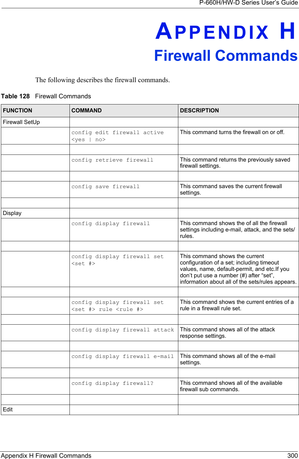
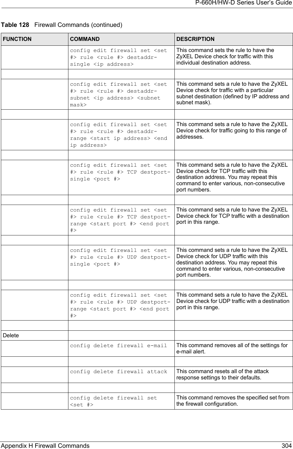

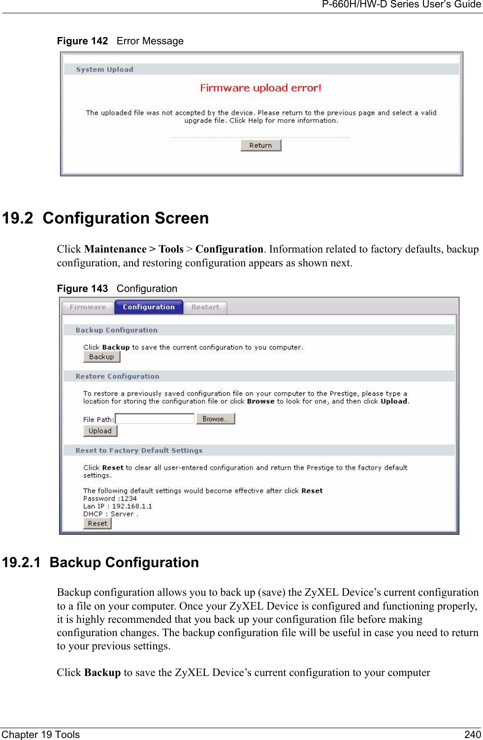
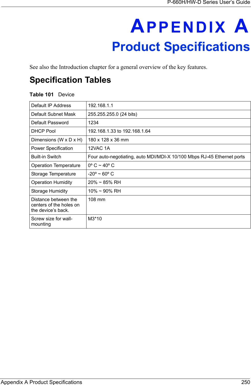
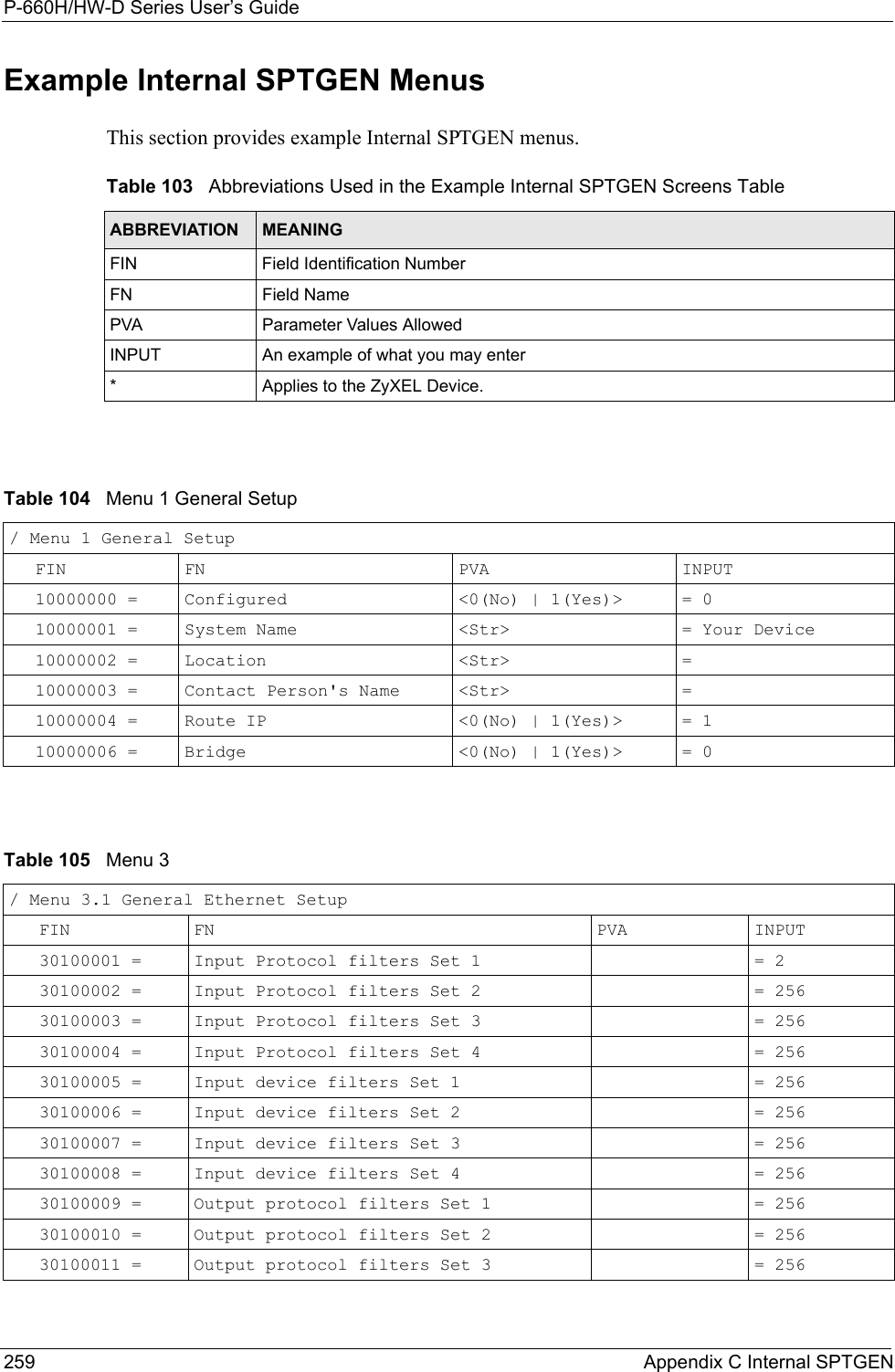
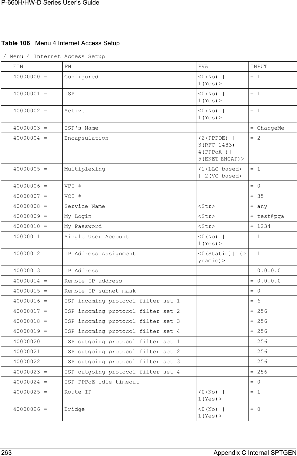
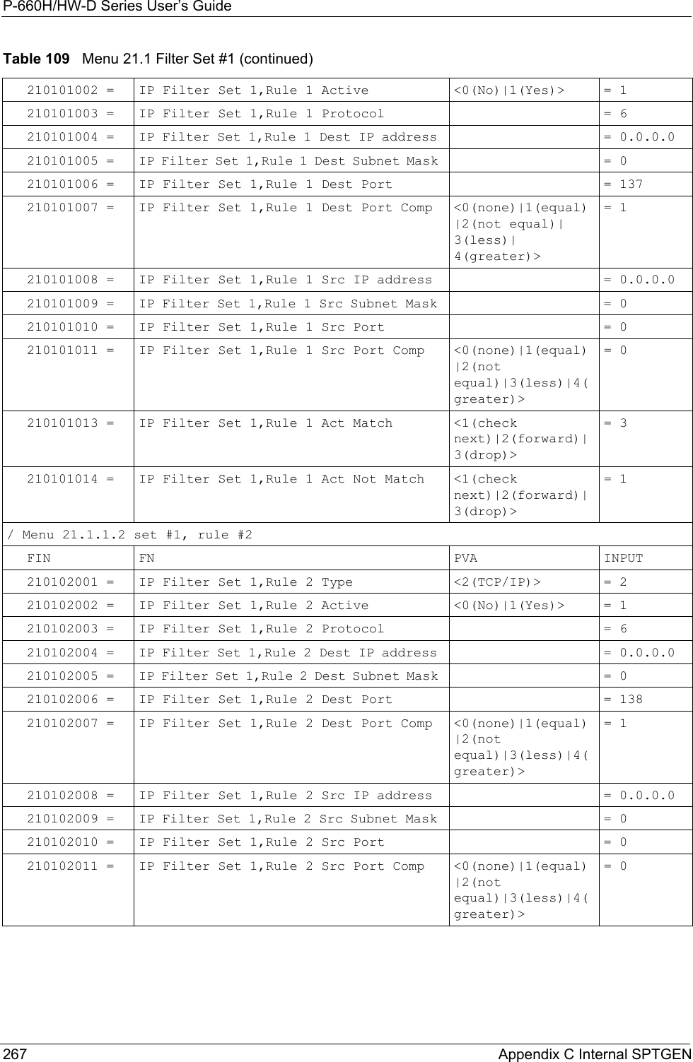
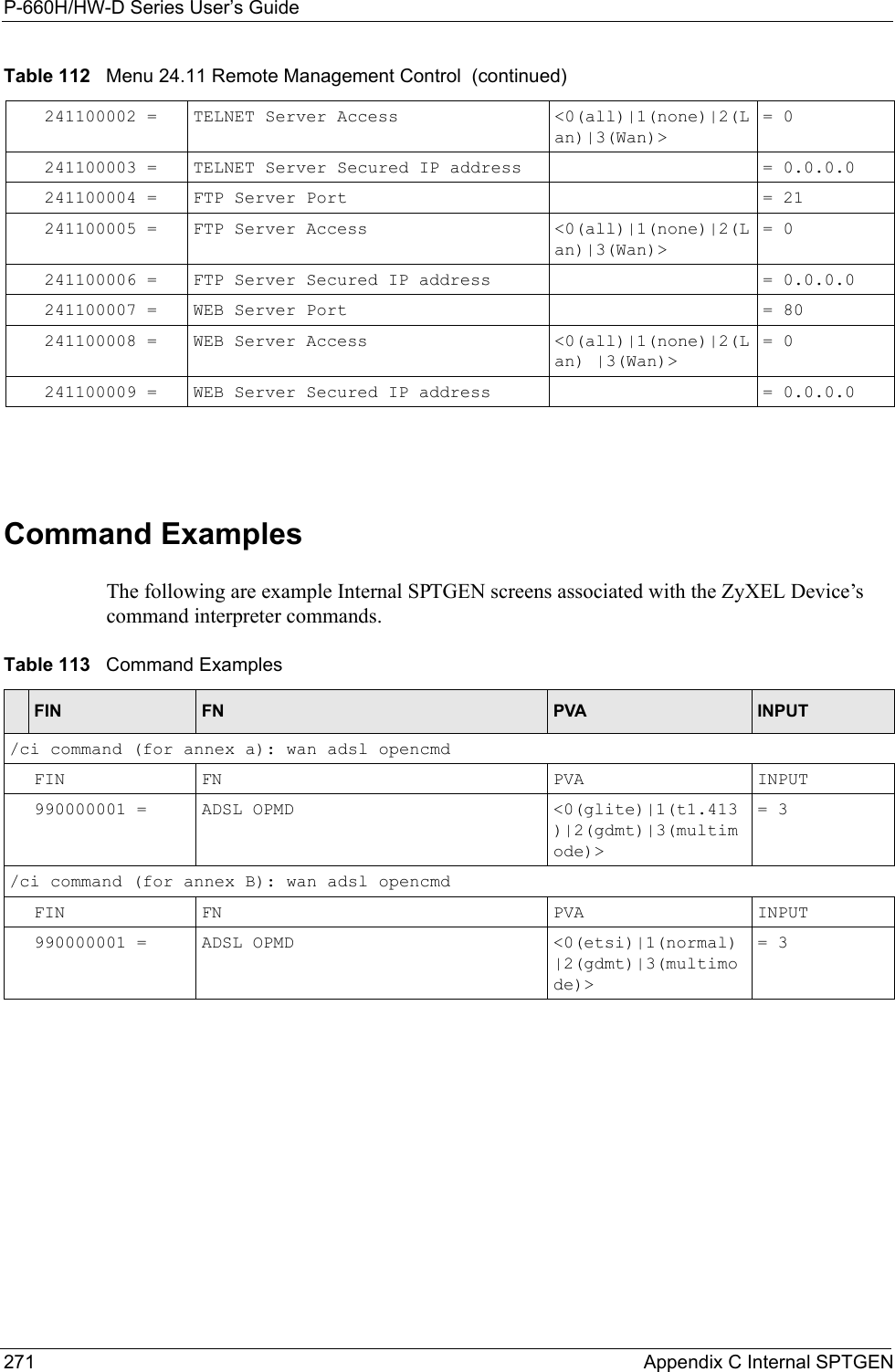
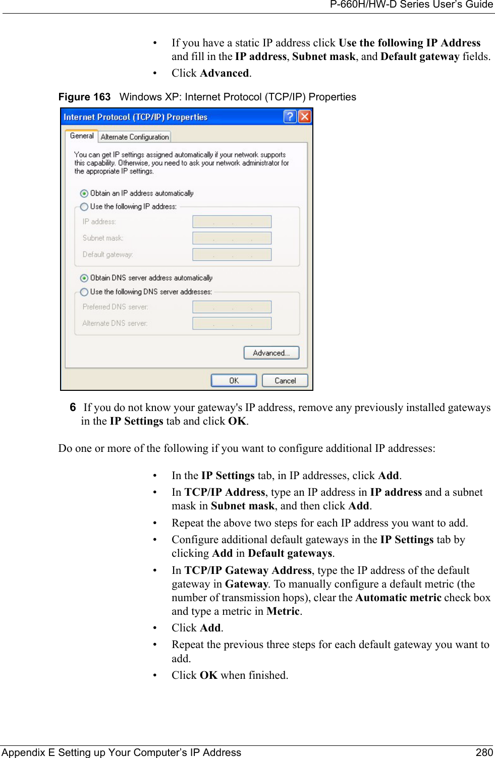
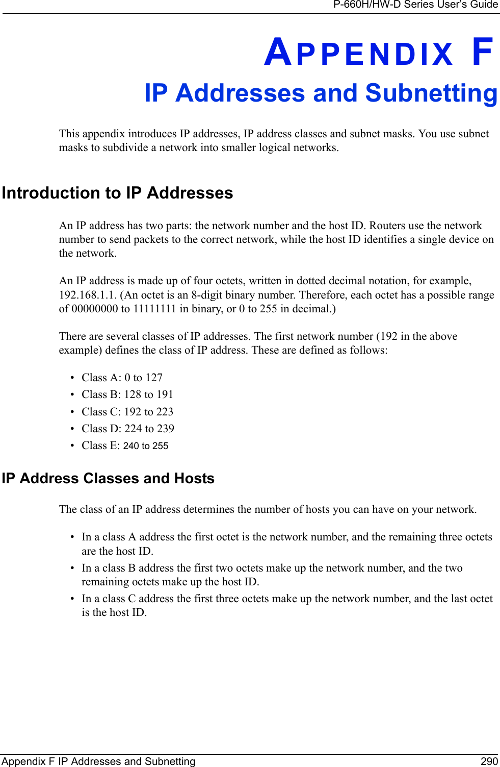
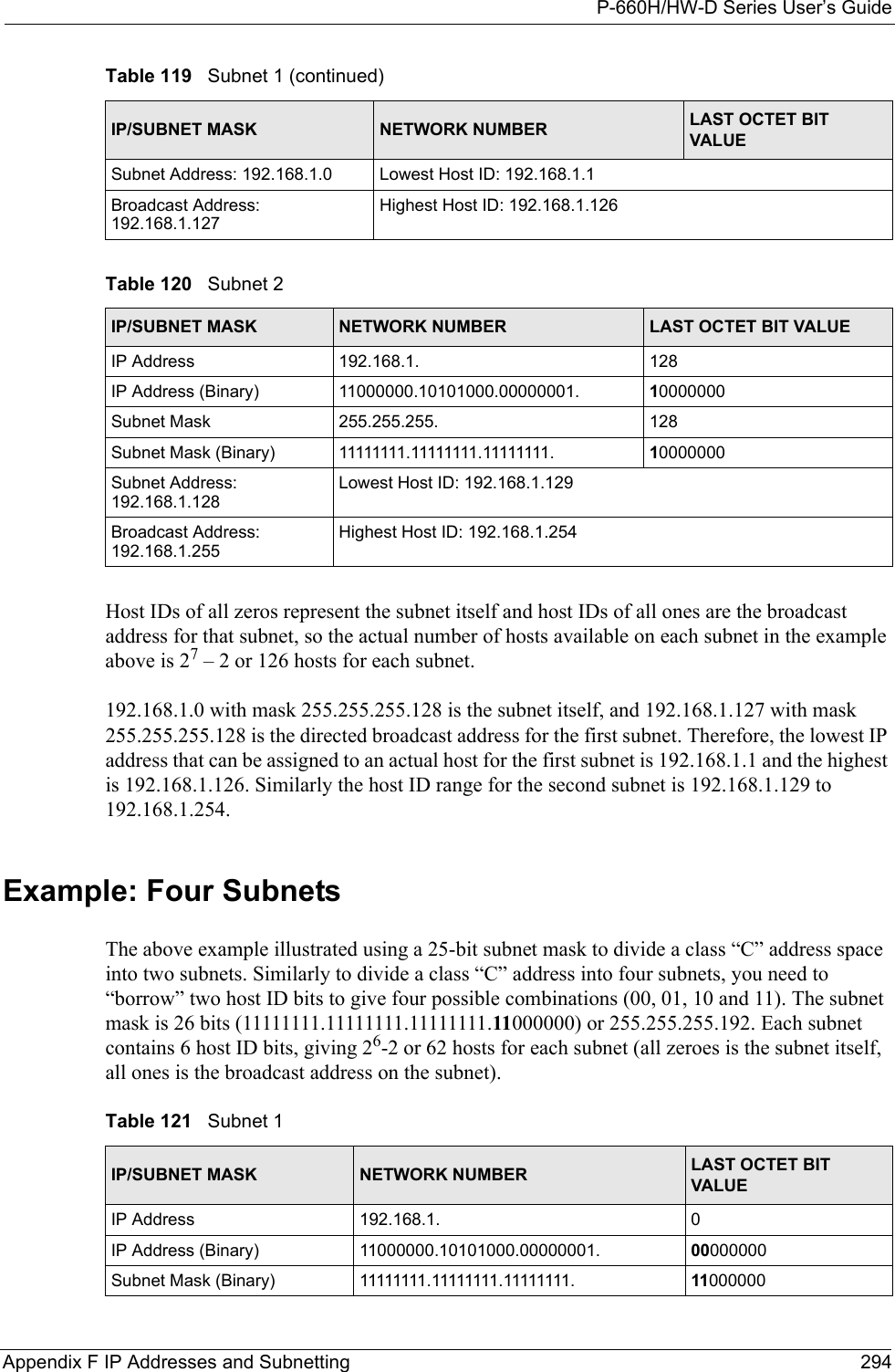
![P-660H/HW-D Series User’s Guide313 Appendix K Log Descriptions Successful HTTPS login Someone has logged on to the router's web configurator interface using HTTPS protocol.HTTPS login failed Someone has failed to log on to the router's web configurator interface using HTTPS protocol.Table 131 System Error LogsLOG MESSAGE DESCRIPTION%s exceeds the max. number of session per host!This attempt to create a NAT session exceeds the maximum number of NAT session table entries allowed to be created per host.setNetBIOSFilter: calloc errorThe router failed to allocate memory for the NetBIOS filter settings.readNetBIOSFilter: calloc errorThe router failed to allocate memory for the NetBIOS filter settings.WAN connection is down. A WAN connection is down. You cannot access the network through this interface.Table 132 Access Control LogsLOG MESSAGE DESCRIPTIONFirewall default policy: [TCP | UDP | IGMP | ESP | GRE | OSPF] <Packet Direction>Attempted TCP/UDP/IGMP/ESP/GRE/OSPF access matched the default policy and was blocked or forwarded according to the default policy’s setting.Firewall rule [NOT] match:[TCP | UDP | IGMP | ESP | GRE | OSPF] <Packet Direction>, <rule:%d>Attempted TCP/UDP/IGMP/ESP/GRE/OSPF access matched (or did not match) a configured firewall rule (denoted by its number) and was blocked or forwarded according to the rule. Triangle route packet forwarded: [TCP | UDP | IGMP | ESP | GRE | OSPF]The firewall allowed a triangle route session to pass through.Packet without a NAT table entry blocked: [TCP | UDP | IGMP | ESP | GRE | OSPF]The router blocked a packet that didn't have a corresponding NAT table entry.Router sent blocked web site message: TCPThe router sent a message to notify a user that the router blocked access to a web site that the user requested.Table 130 System Maintenance Logs (continued)LOG MESSAGE DESCRIPTION](https://usermanual.wiki/ZyXEL-Communications/P660HWD1V2.users-manual-6/User-Guide-717832-Page-78.png)