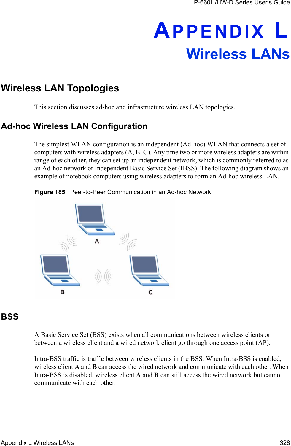
ZyXEL Communications P660HWD1V2 802.11g WIRELESS ADSL2+ 4-PORT GATEWAY User Manual P 660H HW W T Series V3 40 User s Guide
ZyXEL Communications Corporation 802.11g WIRELESS ADSL2+ 4-PORT GATEWAY P 660H HW W T Series V3 40 User s Guide
Contents
users manual7
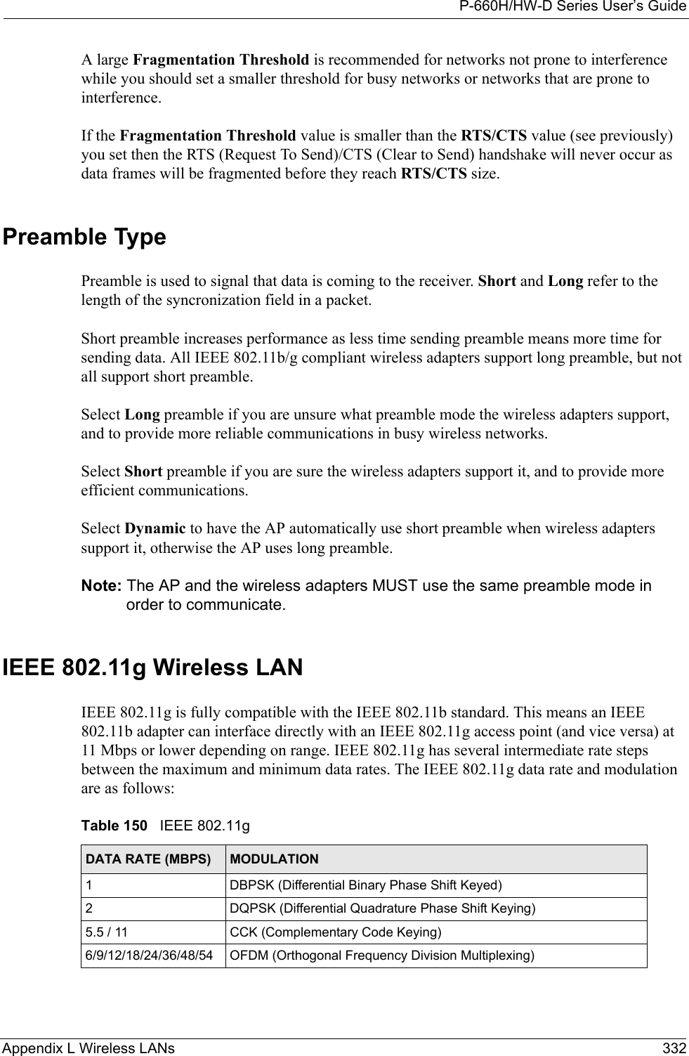
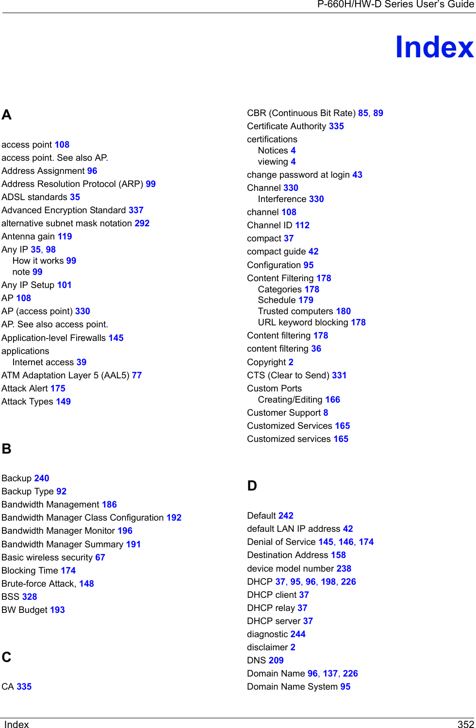
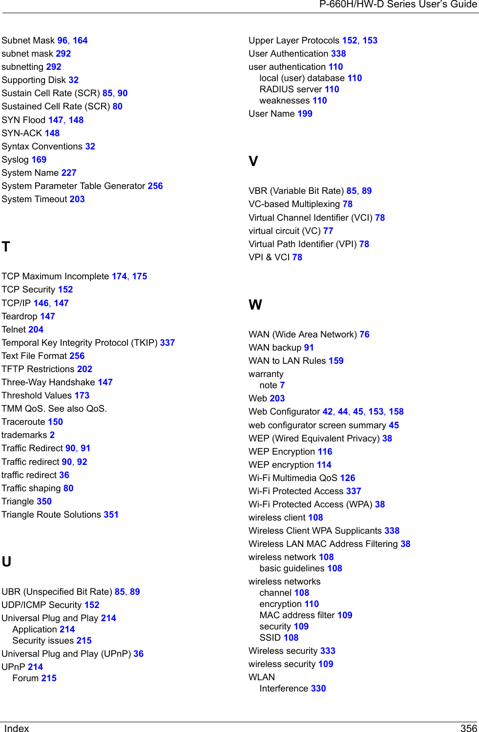
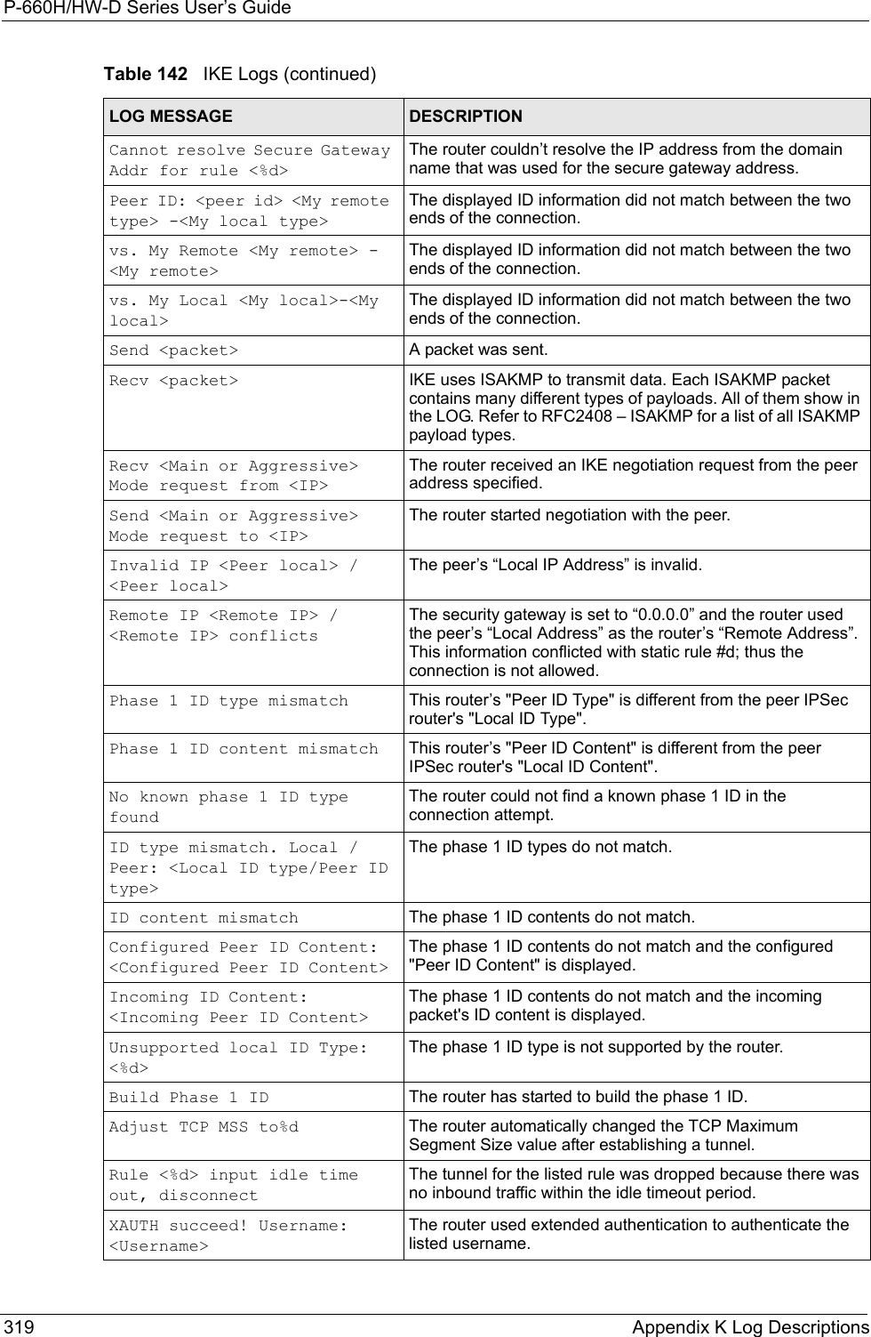
![P-660H/HW-D Series User’s GuideAppendix K Log Descriptions 314 Table 133 TCP Reset LogsLOG MESSAGE DESCRIPTIONUnder SYN flood attack, sent TCP RSTThe router sent a TCP reset packet when a host was under a SYN flood attack (the TCP incomplete count is per destination host.) Exceed TCP MAX incomplete, sent TCP RSTThe router sent a TCP reset packet when the number of TCP incomplete connections exceeded the user configured threshold. (the TCP incomplete count is per destination host.) Note: Refer to TCP Maximum Incomplete in the Firewall Attack Alerts screen. Peer TCP state out of order, sent TCP RSTThe router sent a TCP reset packet when a TCP connection state was out of order.Note: The firewall refers to RFC793 Figure 6 to check the TCP state.Firewall session time out, sent TCP RSTThe router sent a TCP reset packet when a dynamic firewall session timed out.The default timeout values are as follows:ICMP idle timeout: 3 minutesUDP idle timeout: 3 minutesTCP connection (three way handshaking) timeout: 270 secondsTCP FIN-wait timeout: 2 MSL (Maximum Segment Lifetime set in the TCP header).TCP idle (established) timeout (s): 150 minutesTCP reset timeout: 10 secondsExceed MAX incomplete, sent TCP RSTThe router sent a TCP reset packet when the number of incomplete connections (TCP and UDP) exceeded the user-configured threshold. (Incomplete count is for all TCP and UDP connections through the firewall.)Note: When the number of incomplete connections (TCP + UDP) > “Maximum Incomplete High”, the router sends TCP RST packets for TCP connections and destroys TOS (firewall dynamic sessions) until incomplete connections < “Maximum Incomplete Low”.Access block, sent TCP RSTThe router sends a TCP RST packet and generates this log if you turn on the firewall TCP reset mechanism (via CI command: "sys firewall tcprst").Table 134 Packet Filter LogsLOG MESSAGE DESCRIPTION[TCP | UDP | ICMP | IGMP | Generic] packet filter matched (set:%d, rule:%d)Attempted access matched a configured filter rule (denoted by its set and rule number) and was blocked or forwarded according to the rule.](https://usermanual.wiki/ZyXEL-Communications/P660HWD1V2.users-manual7/User-Guide-717833-Page-1.png)
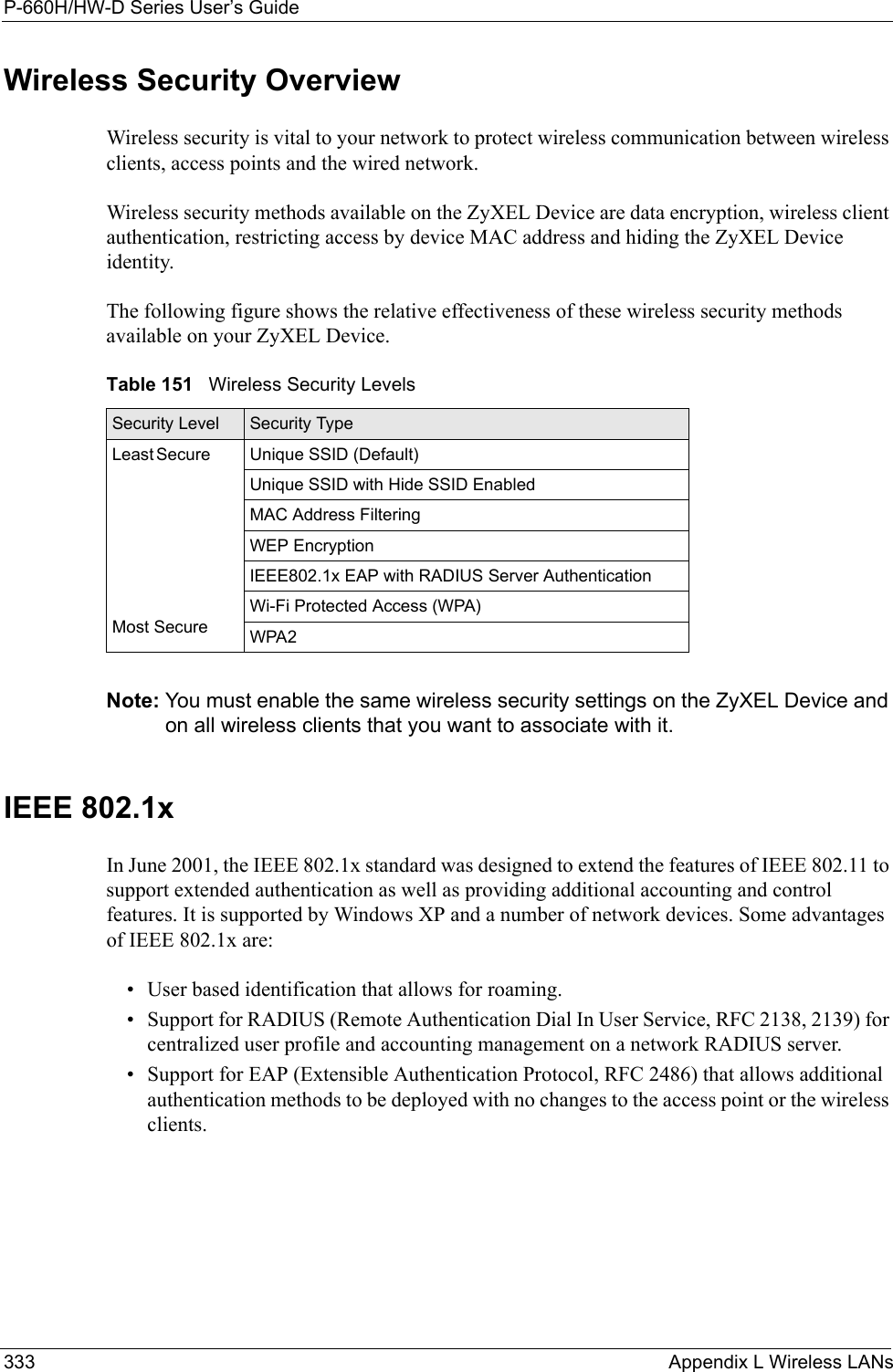
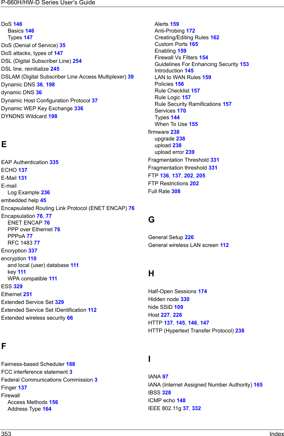
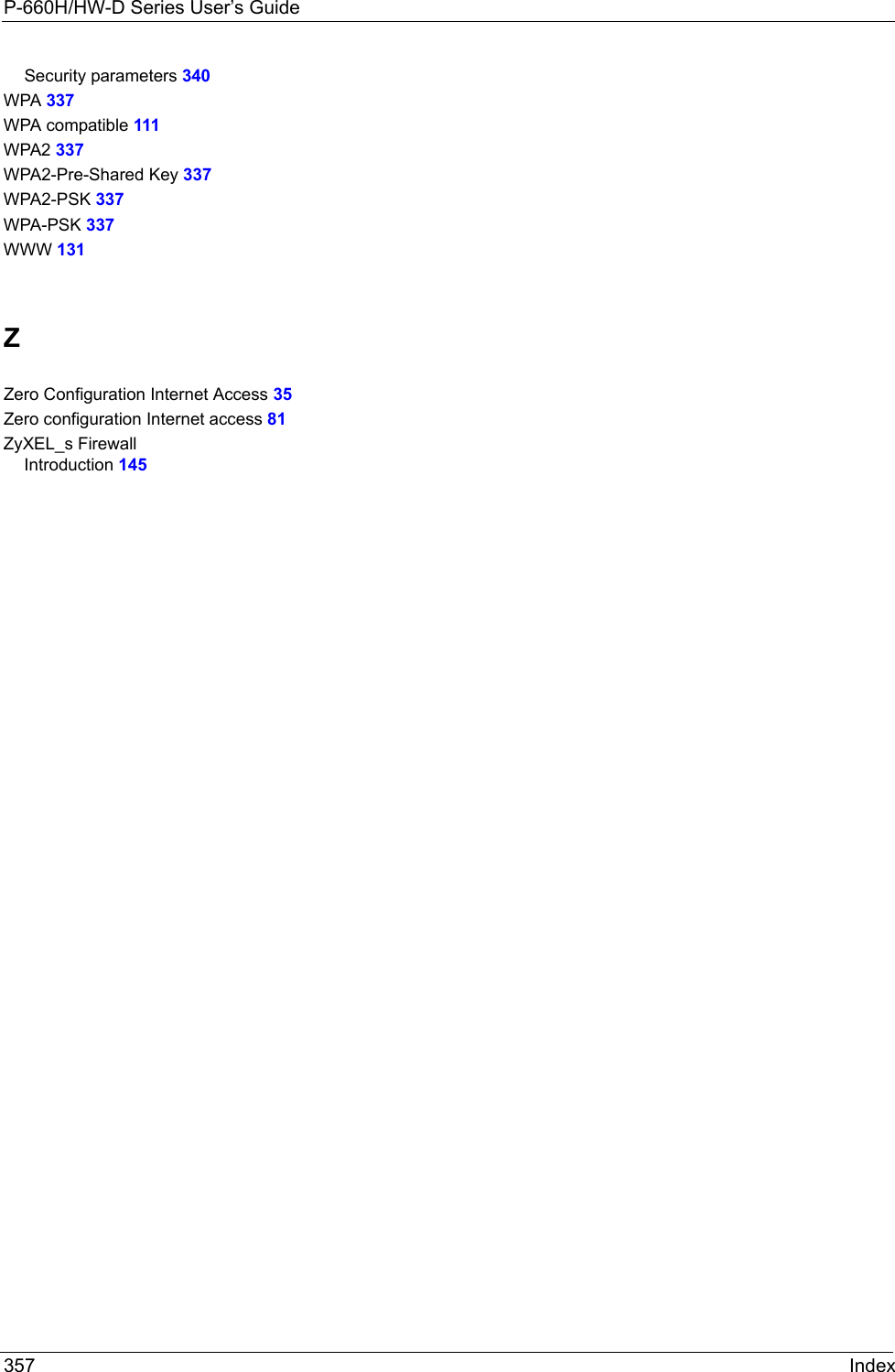
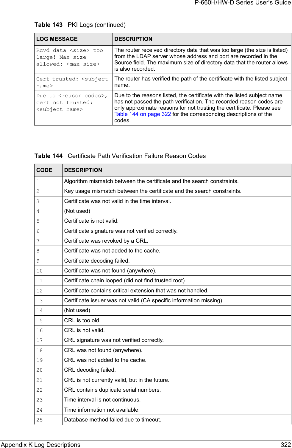
![P-660H/HW-D Series User’s Guide315 Appendix K Log Descriptions Table 135 ICMP LogsLOG MESSAGE DESCRIPTIONFirewall default policy: ICMP <Packet Direction>, <type:%d>, <code:%d>ICMP access matched the default policy and was blocked or forwarded according to the user's setting. For type and code details, see Table 147 on page 324.Firewall rule [NOT] match: ICMP <Packet Direction>, <rule:%d>, <type:%d>, <code:%d>ICMP access matched (or didn’t match) a firewall rule (denoted by its number) and was blocked or forwarded according to the rule. For type and code details, see Table 147 on page 324.Triangle route packet forwarded: ICMPThe firewall allowed a triangle route session to pass through.Packet without a NAT table entry blocked: ICMPThe router blocked a packet that didn’t have a corresponding NAT table entry.Unsupported/out-of-order ICMP: ICMPThe firewall does not support this kind of ICMP packets or the ICMP packets are out of order.Router reply ICMP packet: ICMP The router sent an ICMP reply packet to the sender.Table 136 CDR LogsLOG MESSAGE DESCRIPTIONboard%d line%d channel%d, call%d,%s C01 Outgoing Call dev=%x ch=%x%sThe router received the setup requirements for a call. “call” is the reference (count) number of the call. “dev” is the device type (3 is for dial-up, 6 is for PPPoE, 10 is for PPTP). "channel" or “ch” is the call channel ID.For example,"board 0 line 0 channel 0, call 3, C01 Outgoing Call dev=6 ch=0 "Means the router has dialed to the PPPoE server 3 times.board%d line%d channel%d, call%d,%s C02 OutCall Connected%d%sThe PPPoE, PPTP or dial-up call is connected.board%d line%d channel%d, call%d,%s C02 Call TerminatedThe PPPoE, PPTP or dial-up call was disconnected.Table 137 PPP LogsLOG MESSAGE DESCRIPTIONppp:LCP Starting The PPP connection’s Link Control Protocol stage has started.ppp:LCP Opening The PPP connection’s Link Control Protocol stage is opening.ppp:CHAP Opening The PPP connection’s Challenge Handshake Authentication Protocol stage is opening.ppp:IPCP Starting The PPP connection’s Internet Protocol Control Protocol stage is starting.ppp:IPCP Opening The PPP connection’s Internet Protocol Control Protocol stage is opening.](https://usermanual.wiki/ZyXEL-Communications/P660HWD1V2.users-manual7/User-Guide-717833-Page-2.png)
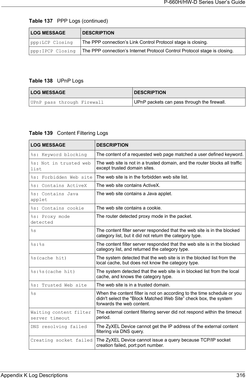
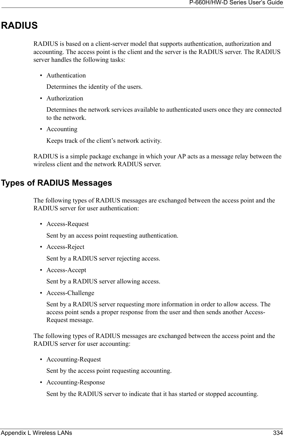
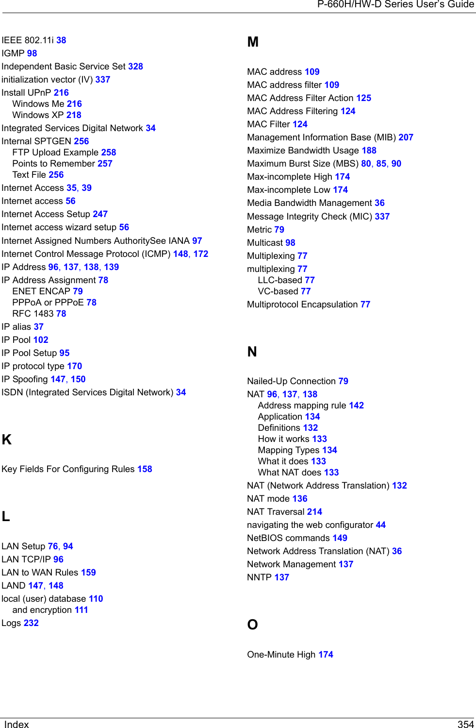
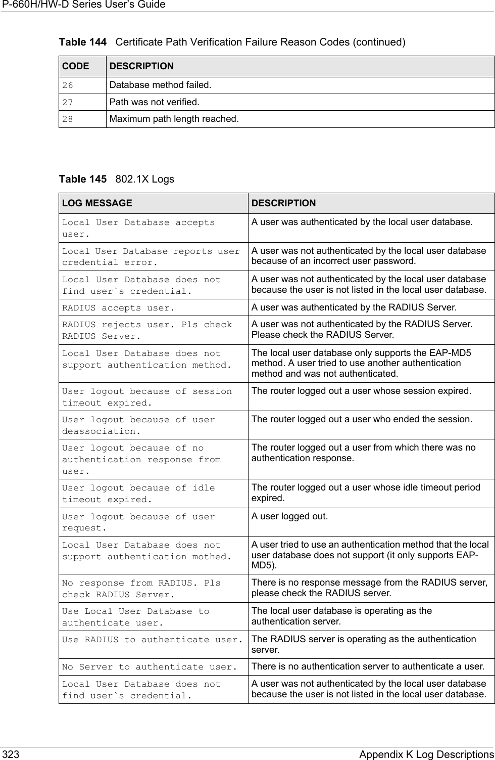
![P-660H/HW-D Series User’s Guide317 Appendix K Log Descriptions Connecting to content filter server failThe connection to the external content filtering server failed.License key is invalid The external content filtering license key is invalid.Table 140 Attack LogsLOG MESSAGE DESCRIPTIONattack [TCP | UDP | IGMP | ESP | GRE | OSPF]The firewall detected a TCP/UDP/IGMP/ESP/GRE/OSPF attack.attack ICMP (type:%d, code:%d)The firewall detected an ICMP attack. For type and code details, see Table 147 on page 324.land [TCP | UDP | IGMP | ESP | GRE | OSPF]The firewall detected a TCP/UDP/IGMP/ESP/GRE/OSPF land attack.land ICMP (type:%d, code:%d)The firewall detected an ICMP land attack. For type and code details, see Table 147 on page 324.ip spoofing - WAN [TCP | UDP | IGMP | ESP | GRE | OSPF]The firewall detected an IP spoofing attack on the WAN port.ip spoofing - WAN ICMP (type:%d, code:%d)The firewall detected an ICMP IP spoofing attack on the WAN port. For type and code details, see Table 147 on page 324.icmp echo: ICMP (type:%d, code:%d)The firewall detected an ICMP echo attack. For type and code details, see Table 147 on page 324.syn flood TCP The firewall detected a TCP syn flood attack.ports scan TCP The firewall detected a TCP port scan attack.teardrop TCP The firewall detected a TCP teardrop attack.teardrop UDP The firewall detected an UDP teardrop attack.teardrop ICMP (type:%d, code:%d)The firewall detected an ICMP teardrop attack. For type and code details, see Table 147 on page 324.illegal command TCP The firewall detected a TCP illegal command attack.NetBIOS TCP The firewall detected a TCP NetBIOS attack.ip spoofing - no routing entry [TCP | UDP | IGMP | ESP | GRE | OSPF]The firewall classified a packet with no source routing entry as an IP spoofing attack.ip spoofing - no routing entry ICMP (type:%d, code:%d)The firewall classified an ICMP packet with no source routing entry as an IP spoofing attack.vulnerability ICMP (type:%d, code:%d)The firewall detected an ICMP vulnerability attack. For type and code details, see Table 147 on page 324.traceroute ICMP (type:%d, code:%d)The firewall detected an ICMP traceroute attack. For type and code details, see Table 147 on page 324.Table 139 Content Filtering Logs (continued)LOG MESSAGE DESCRIPTION](https://usermanual.wiki/ZyXEL-Communications/P660HWD1V2.users-manual7/User-Guide-717833-Page-4.png)
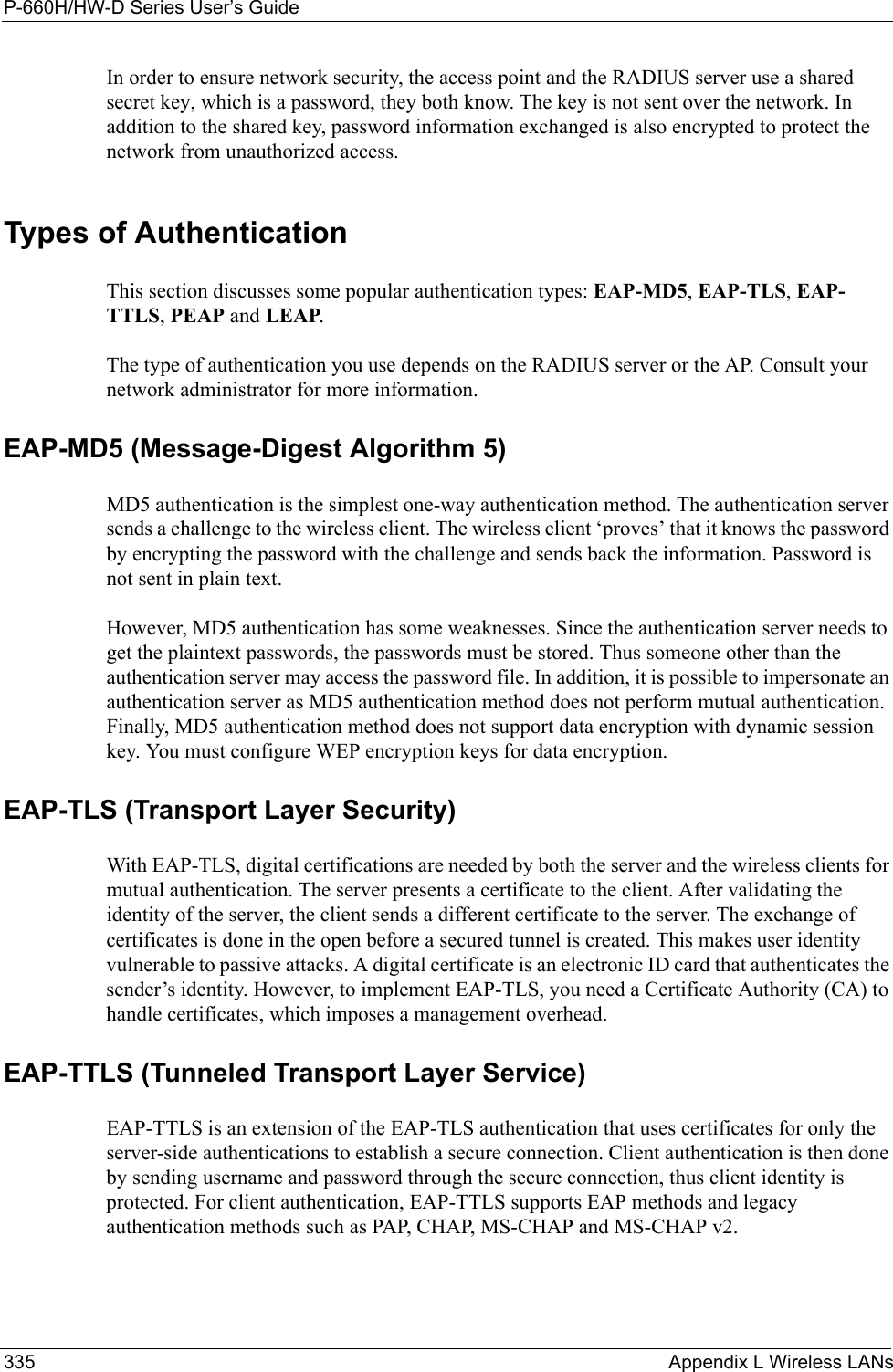
![P-660H/HW-D Series User’s GuideAppendix K Log Descriptions 320XAUTH fail! Username: <Username>The router was not able to use extended authentication to authenticate the listed username.Rule[%d] Phase 1 negotiation mode mismatchThe listed rule’s IKE phase 1 negotiation mode did not match between the router and the peer.Rule [%d] Phase 1 encryption algorithm mismatchThe listed rule’s IKE phase 1 encryption algorithm did not match between the router and the peer.Rule [%d] Phase 1 authentication algorithm mismatchThe listed rule’s IKE phase 1 authentication algorithm did not match between the router and the peer.Rule [%d] Phase 1 authentication method mismatchThe listed rule’s IKE phase 1 authentication method did not match between the router and the peer.Rule [%d] Phase 1 key group mismatchThe listed rule’s IKE phase 1 key group did not match between the router and the peer.Rule [%d] Phase 2 protocol mismatchThe listed rule’s IKE phase 2 protocol did not match between the router and the peer.Rule [%d] Phase 2 encryption algorithm mismatchThe listed rule’s IKE phase 2 encryption algorithm did not match between the router and the peer.Rule [%d] Phase 2 authentication algorithm mismatchThe listed rule’s IKE phase 2 authentication algorithm did not match between the router and the peer.Rule [%d] Phase 2 encapsulation mismatchThe listed rule’s IKE phase 2 encapsulation did not match between the router and the peer.Rule [%d]> Phase 2 pfs mismatchThe listed rule’s IKE phase 2 perfect forward secret (pfs) setting did not match between the router and the peer.Rule [%d] Phase 1 ID mismatch The listed rule’s IKE phase 1 ID did not match between the router and the peer.Rule [%d] Phase 1 hash mismatchThe listed rule’s IKE phase 1 hash did not match between the router and the peer.Rule [%d] Phase 1 preshared key mismatchThe listed rule’s IKE phase 1 pre-shared key did not match between the router and the peer.Rule [%d] Tunnel built successfullyThe listed rule’s IPSec tunnel has been built successfully.Rule [%d] Peer's public key not foundThe listed rule’s IKE phase 1 peer’s public key was not found.Rule [%d] Verify peer's signature failedThe listed rule’s IKE phase 1verification of the peer’s signature failed.Rule [%d] Sending IKE request IKE sent an IKE request for the listed rule.Rule [%d] Receiving IKE requestIKE received an IKE request for the listed rule.Swap rule to rule [%d] The router changed to using the listed rule.Rule [%d] Phase 1 key length mismatchThe listed rule’s IKE phase 1 key length (with the AES encryption algorithm) did not match between the router and the peer.Rule [%d] phase 1 mismatch The listed rule’s IKE phase 1 did not match between the router and the peer.Table 142 IKE Logs (continued)LOG MESSAGE DESCRIPTION](https://usermanual.wiki/ZyXEL-Communications/P660HWD1V2.users-manual7/User-Guide-717833-Page-7.png)
![P-660H/HW-D Series User’s Guide321 Appendix K Log Descriptions Rule [%d] phase 2 mismatch The listed rule’s IKE phase 2 did not match between the router and the peer.Rule [%d] Phase 2 key length mismatchThe listed rule’s IKE phase 2 key lengths (with the AES encryption algorithm) did not match between the router and the peer.Table 143 PKI LogsLOG MESSAGE DESCRIPTIONEnrollment successful The SCEP online certificate enrollment was successful. The Destination field records the certification authority server IP address and port.Enrollment failed The SCEP online certificate enrollment failed. The Destination field records the certification authority server’s IP address and port.Failed to resolve <SCEP CA server url>The SCEP online certificate enrollment failed because the certification authority server’s address cannot be resolved.Enrollment successful The CMP online certificate enrollment was successful. The Destination field records the certification authority server’s IP address and port.Enrollment failed The CMP online certificate enrollment failed. The Destination field records the certification authority server’s IP address and port.Failed to resolve <CMP CA server url>The CMP online certificate enrollment failed because the certification authority server’s IP address cannot be resolved.Rcvd ca cert: <subject name>The router received a certification authority certificate, with subject name as recorded, from the LDAP server whose IP address and port are recorded in the Source field.Rcvd user cert: <subject name>The router received a user certificate, with subject name as recorded, from the LDAP server whose IP address and port are recorded in the Source field.Rcvd CRL <size>: <issuer name>The router received a CRL (Certificate Revocation List), with size and issuer name as recorded, from the LDAP server whose IP address and port are recorded in the Source field.Rcvd ARL <size>: <issuer name>The router received an ARL (Authority Revocation List), with size and issuer name as recorded, from the LDAP server whose address and port are recorded in the Source field.Failed to decode the received ca certThe router received a corrupted certification authority certificate from the LDAP server whose address and port are recorded in the Source field.Failed to decode the received user certThe router received a corrupted user certificate from the LDAP server whose address and port are recorded in the Source field.Failed to decode the received CRLThe router received a corrupted CRL (Certificate Revocation List) from the LDAP server whose address and port are recorded in the Source field.Failed to decode the received ARLThe router received a corrupted ARL (Authority Revocation List) from the LDAP server whose address and port are recorded in the Source field.Table 142 IKE Logs (continued)LOG MESSAGE DESCRIPTION](https://usermanual.wiki/ZyXEL-Communications/P660HWD1V2.users-manual7/User-Guide-717833-Page-8.png)
![P-660H/HW-D Series User’s GuideAppendix K Log Descriptions 326Log CommandsGo to the command interpreter interface. Configuring What You Want the ZyXEL Device to Log1Use the sys logs load command to load the log setting buffer that allows you to configure which logs the ZyXEL Device is to record. 2Use sys logs category to view a list of the log categories.Figure 183 Displaying Log Categories Example3Use sys logs category followed by a log category to display the parameters that are available for the category.Figure 184 Displaying Log Parameters Example4Use sys logs category followed by a log category and a parameter to decide what to record.Use 0 to not record logs for that category, 1 to record only logs for that category, 2 to record only alerts for that category, and 3 to record both logs and alerts for that category. Not every parameter is available with every category.5Use the sys logs save command to store the settings in the ZyXEL Device (you must do this in order to record logs).Displaying Logs• Use the sys logs display command to show all of the logs in the ZyXEL Device’s log.• Use the sys logs category display command to show the log settings for all of the log categories.Copyright (c) 1994 - 2004 ZyXEL Communications Corp.ras>?Valid commands are:sys exit ether auxip ipsec bridge bmcertificates cnm 8021x radiusras>ras> sys logs category accessUsage: [0:none/1:log/2:alert/3:both] [0:don't show debug type/1:show debug type]](https://usermanual.wiki/ZyXEL-Communications/P660HWD1V2.users-manual7/User-Guide-717833-Page-13.png)
![P-660H/HW-D Series User’s Guide327 Appendix K Log Descriptions• Use the sys logs display [log category] command to show the logs in an individual ZyXEL Device log category.• Use the sys logs clear command to erase all of the ZyXEL Device’s logs.Log Command ExampleThis example shows how to set the ZyXEL Device to record the access logs and alerts and then view the results.ras> sys logs loadras> sys logs category access 3ras> sys logs saveras> sys logs display access#.time source destination notes message 0|06/08/2004 05:58:21 |172.21.4.154 |224.0.1.24 |ACCESS BLOCK Firewall default policy: IGMP (W to W) 1|06/08/2004 05:58:20 |172.21.3.56 |239.255.255.250 |ACCESS BLOCK Firewall default policy: IGMP (W to W) 2|06/08/2004 05:58:20 |172.21.0.2 |239.255.255.254 |ACCESS BLOCK Firewall default policy: IGMP (W to W) 3|06/08/2004 05:58:20 |172.21.3.191 |224.0.1.22 |ACCESS BLOCK Firewall default policy: IGMP (W to W) 4|06/08/2004 05:58:20 |172.21.0.254 |224.0.0.1 |ACCESS BLOCK Firewall default policy: IGMP (W to W) 5|06/08/2004 05:58:20 |172.21.4.187:137 |172.21.255.255:137 |ACCESS BLOCK Firewall default policy: UDP (W to W)](https://usermanual.wiki/ZyXEL-Communications/P660HWD1V2.users-manual7/User-Guide-717833-Page-14.png)