ZyXEL Communications P660HWD1V2 802.11g WIRELESS ADSL2+ 4-PORT GATEWAY User Manual P 660H HW W T Series V3 40 User s Guide
ZyXEL Communications Corporation 802.11g WIRELESS ADSL2+ 4-PORT GATEWAY P 660H HW W T Series V3 40 User s Guide
Contents
users manual7

P-660H/HW-D Series User’s Guide
Appendix K Log Descriptions 314
Table 133 TCP Reset Logs
LOG MESSAGE DESCRIPTION
Under SYN flood attack,
sent TCP RST
The router sent a TCP reset packet when a host was under a SYN
flood attack (the TCP incomplete count is per destination host.)
Exceed TCP MAX
incomplete, sent TCP RST
The router sent a TCP reset packet when the number of TCP
incomplete connections exceeded the user configured threshold.
(the TCP incomplete count is per destination host.) Note: Refer to
TCP Maximum Incomplete in the Firewall Attack Alerts screen.
Peer TCP state out of
order, sent TCP RST
The router sent a TCP reset packet when a TCP connection state
was out of order.Note: The firewall refers to RFC793 Figure 6 to
check the TCP state.
Firewall session time
out, sent TCP RST
The router sent a TCP reset packet when a dynamic firewall
session timed out.
The default timeout values are as follows:
ICMP idle timeout: 3 minutes
UDP idle timeout: 3 minutes
TCP connection (three way handshaking) timeout: 270 seconds
TCP FIN-wait timeout: 2 MSL (Maximum Segment Lifetime set in
the TCP header).
TCP idle (established) timeout (s): 150 minutes
TCP reset timeout: 10 seconds
Exceed MAX incomplete,
sent TCP RST
The router sent a TCP reset packet when the number of
incomplete connections (TCP and UDP) exceeded the user-
configured threshold. (Incomplete count is for all TCP and UDP
connections through the firewall.)Note: When the number of
incomplete connections (TCP + UDP) > “Maximum Incomplete
High”, the router sends TCP RST packets for TCP connections
and destroys TOS (firewall dynamic sessions) until incomplete
connections < “Maximum Incomplete Low”.
Access block, sent TCP
RST
The router sends a TCP RST packet and generates this log if you
turn on the firewall TCP reset mechanism (via CI command: "sys
firewall tcprst").
Table 134 Packet Filter Logs
LOG MESSAGE DESCRIPTION
[TCP | UDP | ICMP | IGMP |
Generic] packet filter
matched (set:%d, rule:%d)
Attempted access matched a configured filter rule (denoted by
its set and rule number) and was blocked or forwarded
according to the rule.

P-660H/HW-D Series User’s Guide
315 Appendix K Log Descriptions
Table 135 ICMP Logs
LOG MESSAGE DESCRIPTION
Firewall default policy: ICMP
<Packet Direction>, <type:%d>,
<code:%d>
ICMP access matched the default policy and was blocked
or forwarded according to the user's setting. For type and
code details, see Table 147 on page 324.
Firewall rule [NOT] match: ICMP
<Packet Direction>, <rule:%d>,
<type:%d>, <code:%d>
ICMP access matched (or didn’t match) a firewall rule
(denoted by its number) and was blocked or forwarded
according to the rule. For type and code details, see
Table 147 on page 324.
Triangle route packet forwarded:
ICMP
The firewall allowed a triangle route session to pass
through.
Packet without a NAT table entry
blocked: ICMP
The router blocked a packet that didn’t have a
corresponding NAT table entry.
Unsupported/out-of-order ICMP:
ICMP
The firewall does not support this kind of ICMP packets or
the ICMP packets are out of order.
Router reply ICMP packet: ICMP The router sent an ICMP reply packet to the sender.
Table 136 CDR Logs
LOG MESSAGE DESCRIPTION
board%d line%d channel%d,
call%d,%s C01 Outgoing Call
dev=%x ch=%x%s
The router received the setup requirements for a call. “call” is
the reference (count) number of the call. “dev” is the device
type (3 is for dial-up, 6 is for PPPoE, 10 is for PPTP).
"channel" or “ch” is the call channel ID.For example,"board 0
line 0 channel 0, call 3, C01 Outgoing Call dev=6 ch=0
"Means the router has dialed to the PPPoE server 3 times.
board%d line%d channel%d,
call%d,%s C02 OutCall
Connected%d%s
The PPPoE, PPTP or dial-up call is connected.
board%d line%d channel%d,
call%d,%s C02 Call Terminated
The PPPoE, PPTP or dial-up call was disconnected.
Table 137 PPP Logs
LOG MESSAGE DESCRIPTION
ppp:LCP Starting The PPP connection’s Link Control Protocol stage has started.
ppp:LCP Opening The PPP connection’s Link Control Protocol stage is opening.
ppp:CHAP Opening The PPP connection’s Challenge Handshake Authentication Protocol stage is
opening.
ppp:IPCP Starting The PPP connection’s Internet Protocol Control Protocol stage is starting.
ppp:IPCP Opening The PPP connection’s Internet Protocol Control Protocol stage is opening.

P-660H/HW-D Series User’s Guide
Appendix K Log Descriptions 316
ppp:LCP Closing The PPP connection’s Link Control Protocol stage is closing.
ppp:IPCP Closing The PPP connection’s Internet Protocol Control Protocol stage is closing.
Table 138 UPnP Logs
LOG MESSAGE DESCRIPTION
UPnP pass through Firewall UPnP packets can pass through the firewall.
Table 139 Content Filtering Logs
LOG MESSAGE DESCRIPTION
%s: Keyword blocking The content of a requested web page matched a user defined keyword.
%s: Not in trusted web
list
The web site is not in a trusted domain, and the router blocks all traffic
except trusted domain sites.
%s: Forbidden Web site The web site is in the forbidden web site list.
%s: Contains ActiveX The web site contains ActiveX.
%s: Contains Java
applet
The web site contains a Java applet.
%s: Contains cookie The web site contains a cookie.
%s: Proxy mode
detected
The router detected proxy mode in the packet.
%s The content filter server responded that the web site is in the blocked
category list, but it did not return the category type.
%s:%s The content filter server responded that the web site is in the blocked
category list, and returned the category type.
%s(cache hit) The system detected that the web site is in the blocked list from the
local cache, but does not know the category type.
%s:%s(cache hit) The system detected that the web site is in blocked list from the local
cache, and knows the category type.
%s: Trusted Web site The web site is in a trusted domain.
%s When the content filter is not on according to the time schedule or you
didn't select the "Block Matched Web Site” check box, the system
forwards the web content.
Waiting content filter
server timeout
The external content filtering server did not respond within the timeout
period.
DNS resolving failed The ZyXEL Device cannot get the IP address of the external content
filtering via DNS query.
Creating socket failed The ZyXEL Device cannot issue a query because TCP/IP socket
creation failed, port:port number.
Table 137 PPP Logs (continued)
LOG MESSAGE DESCRIPTION

P-660H/HW-D Series User’s Guide
317 Appendix K Log Descriptions
Connecting to content
filter server fail
The connection to the external content filtering server failed.
License key is invalid The external content filtering license key is invalid.
Table 140 Attack Logs
LOG MESSAGE DESCRIPTION
attack [TCP | UDP | IGMP |
ESP | GRE | OSPF]
The firewall detected a TCP/UDP/IGMP/ESP/GRE/OSPF attack.
attack ICMP (type:%d,
code:%d)
The firewall detected an ICMP attack. For type and code details,
see Table 147 on page 324.
land [TCP | UDP | IGMP |
ESP | GRE | OSPF]
The firewall detected a TCP/UDP/IGMP/ESP/GRE/OSPF land
attack.
land ICMP (type:%d,
code:%d)
The firewall detected an ICMP land attack. For type and code
details, see Table 147 on page 324.
ip spoofing - WAN [TCP |
UDP | IGMP | ESP | GRE |
OSPF]
The firewall detected an IP spoofing attack on the WAN port.
ip spoofing - WAN ICMP
(type:%d, code:%d)
The firewall detected an ICMP IP spoofing attack on the WAN port.
For type and code details, see Table 147 on page 324.
icmp echo: ICMP (type:%d,
code:%d)
The firewall detected an ICMP echo attack. For type and code
details, see Table 147 on page 324.
syn flood TCP The firewall detected a TCP syn flood attack.
ports scan TCP The firewall detected a TCP port scan attack.
teardrop TCP The firewall detected a TCP teardrop attack.
teardrop UDP The firewall detected an UDP teardrop attack.
teardrop ICMP (type:%d,
code:%d)
The firewall detected an ICMP teardrop attack. For type and code
details, see Table 147 on page 324.
illegal command TCP The firewall detected a TCP illegal command attack.
NetBIOS TCP The firewall detected a TCP NetBIOS attack.
ip spoofing - no routing
entry [TCP | UDP | IGMP |
ESP | GRE | OSPF]
The firewall classified a packet with no source routing entry as an
IP spoofing attack.
ip spoofing - no routing
entry ICMP (type:%d,
code:%d)
The firewall classified an ICMP packet with no source routing entry
as an IP spoofing attack.
vulnerability ICMP
(type:%d, code:%d)
The firewall detected an ICMP vulnerability attack. For type and
code details, see Table 147 on page 324.
traceroute ICMP (type:%d,
code:%d)
The firewall detected an ICMP traceroute attack. For type and
code details, see Table 147 on page 324.
Table 139 Content Filtering Logs (continued)
LOG MESSAGE DESCRIPTION

P-660H/HW-D Series User’s Guide
Appendix K Log Descriptions 318
Table 141 IPSec Logs
LOG MESSAGE DESCRIPTION
Discard REPLAY packet The router received and discarded a packet with an incorrect
sequence number.
Inbound packet
authentication failed
The router received a packet that has been altered. A third party may
have altered or tampered with the packet.
Receive IPSec packet,
but no corresponding
tunnel exists
The router dropped an inbound packet for which SPI could not find a
corresponding phase 2 SA.
Rule <%d> idle time out,
disconnect
The router dropped a connection that had outbound traffic and no
inbound traffic for a certain time period. You can use the "ipsec timer
chk_conn" CI command to set the time period. The default value is 2
minutes.
WAN IP changed to <IP> The router dropped all connections with the “MyIP” configured as
“0.0.0.0” when the WAN IP address changed.
Table 142 IKE Logs
LOG MESSAGE DESCRIPTION
Active connection allowed
exceeded
The IKE process for a new connection failed because the limit
of simultaneous phase 2 SAs has been reached.
Start Phase 2: Quick Mode Phase 2 Quick Mode has started.
Verifying Remote ID failed: The connection failed during IKE phase 2 because the router
and the peer’s Local/Remote Addresses don’t match.
Verifying Local ID failed: The connection failed during IKE phase 2 because the router
and the peer’s Local/Remote Addresses don’t match.
IKE Packet Retransmit The router retransmitted the last packet sent because there
was no response from the peer.
Failed to send IKE Packet An Ethernet error stopped the router from sending IKE
packets.
Too many errors! Deleting SA An SA was deleted because there were too many errors.
Phase 1 IKE SA process done The phase 1 IKE SA process has been completed.
Duplicate requests with the
same cookie
The router received multiple requests from the same peer
while still processing the first IKE packet from the peer.
IKE Negotiation is in process The router has already started negotiating with the peer for
the connection, but the IKE process has not finished yet.
No proposal chosen Phase 1 or phase 2 parameters don’t match. Please check all
protocols / settings. Ex. One device being configured for
3DES and the other being configured for DES causes the
connection to fail.
Local / remote IPs of
incoming request conflict
with rule <%d>
The security gateway is set to “0.0.0.0” and the router used
the peer’s “Local Address” as the router’s “Remote Address”.
This information conflicted with static rule #d; thus the
connection is not allowed.

P-660H/HW-D Series User’s Guide
319 Appendix K Log Descriptions
Cannot resolve Secure Gateway
Addr for rule <%d>
The router couldn’t resolve the IP address from the domain
name that was used for the secure gateway address.
Peer ID: <peer id> <My remote
type> -<My local type>
The displayed ID information did not match between the two
ends of the connection.
vs. My Remote <My remote> -
<My remote>
The displayed ID information did not match between the two
ends of the connection.
vs. My Local <My local>-<My
local>
The displayed ID information did not match between the two
ends of the connection.
Send <packet> A packet was sent.
Recv <packet> IKE uses ISAKMP to transmit data. Each ISAKMP packet
contains many different types of payloads. All of them show in
the LOG. Refer to RFC2408 – ISAKMP for a list of all ISAKMP
payload types.
Recv <Main or Aggressive>
Mode request from <IP>
The router received an IKE negotiation request from the peer
address specified.
Send <Main or Aggressive>
Mode request to <IP>
The router started negotiation with the peer.
Invalid IP <Peer local> /
<Peer local>
The peer’s “Local IP Address” is invalid.
Remote IP <Remote IP> /
<Remote IP> conflicts
The security gateway is set to “0.0.0.0” and the router used
the peer’s “Local Address” as the router’s “Remote Address”.
This information conflicted with static rule #d; thus the
connection is not allowed.
Phase 1 ID type mismatch This router’s "Peer ID Type" is different from the peer IPSec
router's "Local ID Type".
Phase 1 ID content mismatch This router’s "Peer ID Content" is different from the peer
IPSec router's "Local ID Content".
No known phase 1 ID type
found
The router could not find a known phase 1 ID in the
connection attempt.
ID type mismatch. Local /
Peer: <Local ID type/Peer ID
type>
The phase 1 ID types do not match.
ID content mismatch The phase 1 ID contents do not match.
Configured Peer ID Content:
<Configured Peer ID Content>
The phase 1 ID contents do not match and the configured
"Peer ID Content" is displayed.
Incoming ID Content:
<Incoming Peer ID Content>
The phase 1 ID contents do not match and the incoming
packet's ID content is displayed.
Unsupported local ID Type:
<%d>
The phase 1 ID type is not supported by the router.
Build Phase 1 ID The router has started to build the phase 1 ID.
Adjust TCP MSS to%d The router automatically changed the TCP Maximum
Segment Size value after establishing a tunnel.
Rule <%d> input idle time
out, disconnect
The tunnel for the listed rule was dropped because there was
no inbound traffic within the idle timeout period.
XAUTH succeed! Username:
<Username>
The router used extended authentication to authenticate the
listed username.
Table 142 IKE Logs (continued)
LOG MESSAGE DESCRIPTION

P-660H/HW-D Series User’s Guide
Appendix K Log Descriptions 320
XAUTH fail! Username:
<Username>
The router was not able to use extended authentication to
authenticate the listed username.
Rule[%d] Phase 1 negotiation
mode mismatch
The listed rule’s IKE phase 1 negotiation mode did not match
between the router and the peer.
Rule [%d] Phase 1 encryption
algorithm mismatch
The listed rule’s IKE phase 1 encryption algorithm did not
match between the router and the peer.
Rule [%d] Phase 1
authentication algorithm
mismatch
The listed rule’s IKE phase 1 authentication algorithm did not
match between the router and the peer.
Rule [%d] Phase 1
authentication method
mismatch
The listed rule’s IKE phase 1 authentication method did not
match between the router and the peer.
Rule [%d] Phase 1 key group
mismatch
The listed rule’s IKE phase 1 key group did not match
between the router and the peer.
Rule [%d] Phase 2 protocol
mismatch
The listed rule’s IKE phase 2 protocol did not match between
the router and the peer.
Rule [%d] Phase 2 encryption
algorithm mismatch
The listed rule’s IKE phase 2 encryption algorithm did not
match between the router and the peer.
Rule [%d] Phase 2
authentication algorithm
mismatch
The listed rule’s IKE phase 2 authentication algorithm did not
match between the router and the peer.
Rule [%d] Phase 2
encapsulation mismatch
The listed rule’s IKE phase 2 encapsulation did not match
between the router and the peer.
Rule [%d]> Phase 2 pfs
mismatch
The listed rule’s IKE phase 2 perfect forward secret (pfs)
setting did not match between the router and the peer.
Rule [%d] Phase 1 ID mismatch The listed rule’s IKE phase 1 ID did not match between the
router and the peer.
Rule [%d] Phase 1 hash
mismatch
The listed rule’s IKE phase 1 hash did not match between the
router and the peer.
Rule [%d] Phase 1 preshared
key mismatch
The listed rule’s IKE phase 1 pre-shared key did not match
between the router and the peer.
Rule [%d] Tunnel built
successfully
The listed rule’s IPSec tunnel has been built successfully.
Rule [%d] Peer's public key
not found
The listed rule’s IKE phase 1 peer’s public key was not found.
Rule [%d] Verify peer's
signature failed
The listed rule’s IKE phase 1verification of the peer’s
signature failed.
Rule [%d] Sending IKE request IKE sent an IKE request for the listed rule.
Rule [%d] Receiving IKE
request
IKE received an IKE request for the listed rule.
Swap rule to rule [%d] The router changed to using the listed rule.
Rule [%d] Phase 1 key length
mismatch
The listed rule’s IKE phase 1 key length (with the AES
encryption algorithm) did not match between the router and
the peer.
Rule [%d] phase 1 mismatch The listed rule’s IKE phase 1 did not match between the router
and the peer.
Table 142 IKE Logs (continued)
LOG MESSAGE DESCRIPTION

P-660H/HW-D Series User’s Guide
321 Appendix K Log Descriptions
Rule [%d] phase 2 mismatch The listed rule’s IKE phase 2 did not match between the router
and the peer.
Rule [%d] Phase 2 key length
mismatch
The listed rule’s IKE phase 2 key lengths (with the AES
encryption algorithm) did not match between the router and
the peer.
Table 143 PKI Logs
LOG MESSAGE DESCRIPTION
Enrollment successful The SCEP online certificate enrollment was successful. The
Destination field records the certification authority server IP address
and port.
Enrollment failed The SCEP online certificate enrollment failed. The Destination field
records the certification authority server’s IP address and port.
Failed to resolve
<SCEP CA server url>
The SCEP online certificate enrollment failed because the certification
authority server’s address cannot be resolved.
Enrollment successful The CMP online certificate enrollment was successful. The Destination
field records the certification authority server’s IP address and port.
Enrollment failed The CMP online certificate enrollment failed. The Destination field
records the certification authority server’s IP address and port.
Failed to resolve <CMP
CA server url>
The CMP online certificate enrollment failed because the certification
authority server’s IP address cannot be resolved.
Rcvd ca cert: <subject
name>
The router received a certification authority certificate, with subject
name as recorded, from the LDAP server whose IP address and port
are recorded in the Source field.
Rcvd user cert:
<subject name>
The router received a user certificate, with subject name as recorded,
from the LDAP server whose IP address and port are recorded in the
Source field.
Rcvd CRL <size>:
<issuer name>
The router received a CRL (Certificate Revocation List), with size and
issuer name as recorded, from the LDAP server whose IP address and
port are recorded in the Source field.
Rcvd ARL <size>:
<issuer name>
The router received an ARL (Authority Revocation List), with size and
issuer name as recorded, from the LDAP server whose address and
port are recorded in the Source field.
Failed to decode the
received ca cert
The router received a corrupted certification authority certificate from
the LDAP server whose address and port are recorded in the Source
field.
Failed to decode the
received user cert
The router received a corrupted user certificate from the LDAP server
whose address and port are recorded in the Source field.
Failed to decode the
received CRL
The router received a corrupted CRL (Certificate Revocation List) from
the LDAP server whose address and port are recorded in the Source
field.
Failed to decode the
received ARL
The router received a corrupted ARL (Authority Revocation List) from
the LDAP server whose address and port are recorded in the Source
field.
Table 142 IKE Logs (continued)
LOG MESSAGE DESCRIPTION

P-660H/HW-D Series User’s Guide
Appendix K Log Descriptions 322
Rcvd data <size> too
large! Max size
allowed: <max size>
The router received directory data that was too large (the size is listed)
from the LDAP server whose address and port are recorded in the
Source field. The maximum size of directory data that the router allows
is also recorded.
Cert trusted: <subject
name>
The router has verified the path of the certificate with the listed subject
name.
Due to <reason codes>,
cert not trusted:
<subject name>
Due to the reasons listed, the certificate with the listed subject name
has not passed the path verification. The recorded reason codes are
only approximate reasons for not trusting the certificate. Please see
Table 144 on page 322 for the corresponding descriptions of the
codes.
Table 144 Certificate Path Verification Failure Reason Codes
CODE DESCRIPTION
1Algorithm mismatch between the certificate and the search constraints.
2Key usage mismatch between the certificate and the search constraints.
3Certificate was not valid in the time interval.
4(Not used)
5Certificate is not valid.
6Certificate signature was not verified correctly.
7Certificate was revoked by a CRL.
8Certificate was not added to the cache.
9Certificate decoding failed.
10 Certificate was not found (anywhere).
11 Certificate chain looped (did not find trusted root).
12 Certificate contains critical extension that was not handled.
13 Certificate issuer was not valid (CA specific information missing).
14 (Not used)
15 CRL is too old.
16 CRL is not valid.
17 CRL signature was not verified correctly.
18 CRL was not found (anywhere).
19 CRL was not added to the cache.
20 CRL decoding failed.
21 CRL is not currently valid, but in the future.
22 CRL contains duplicate serial numbers.
23 Time interval is not continuous.
24 Time information not available.
25 Database method failed due to timeout.
Table 143 PKI Logs (continued)
LOG MESSAGE DESCRIPTION

P-660H/HW-D Series User’s Guide
323 Appendix K Log Descriptions
26 Database method failed.
27 Path was not verified.
28 Maximum path length reached.
Table 145 802.1X Logs
LOG MESSAGE DESCRIPTION
Local User Database accepts
user.
A user was authenticated by the local user database.
Local User Database reports user
credential error.
A user was not authenticated by the local user database
because of an incorrect user password.
Local User Database does not
find user`s credential.
A user was not authenticated by the local user database
because the user is not listed in the local user database.
RADIUS accepts user. A user was authenticated by the RADIUS Server.
RADIUS rejects user. Pls check
RADIUS Server.
A user was not authenticated by the RADIUS Server.
Please check the RADIUS Server.
Local User Database does not
support authentication method.
The local user database only supports the EAP-MD5
method. A user tried to use another authentication
method and was not authenticated.
User logout because of session
timeout expired.
The router logged out a user whose session expired.
User logout because of user
deassociation.
The router logged out a user who ended the session.
User logout because of no
authentication response from
user.
The router logged out a user from which there was no
authentication response.
User logout because of idle
timeout expired.
The router logged out a user whose idle timeout period
expired.
User logout because of user
request.
A user logged out.
Local User Database does not
support authentication mothed.
A user tried to use an authentication method that the local
user database does not support (it only supports EAP-
MD5).
No response from RADIUS. Pls
check RADIUS Server.
There is no response message from the RADIUS server,
please check the RADIUS server.
Use Local User Database to
authenticate user.
The local user database is operating as the
authentication server.
Use RADIUS to authenticate user. The RADIUS server is operating as the authentication
server.
No Server to authenticate user. There is no authentication server to authenticate a user.
Local User Database does not
find user`s credential.
A user was not authenticated by the local user database
because the user is not listed in the local user database.
Table 144 Certificate Path Verification Failure Reason Codes (continued)
CODE DESCRIPTION

P-660H/HW-D Series User’s Guide
Appendix K Log Descriptions 324
Table 146 ACL Setting Notes
PACKET DIRECTION DIRECTION DESCRIPTION
(L to W) LAN to WAN ACL set for packets traveling from the LAN to the WAN.
(W to L) WAN to LAN ACL set for packets traveling from the WAN to the LAN.
(L to L) LAN to LAN/
ZyXEL Device
ACL set for packets traveling from the LAN to the LAN or
the ZyXEL Device.
(W to W) WAN to WAN/
ZyXEL Device
ACL set for packets traveling from the WAN to the WAN
or the ZyXEL Device.
Table 147 ICMP Notes
TYPE CODE DESCRIPTION
0Echo Reply
0Echo reply message
3Destination Unreachable
0Net unreachable
1Host unreachable
2Protocol unreachable
3Port unreachable
4A packet that needed fragmentation was dropped because it was set to Don't
Fragment (DF)
5Source route failed
4Source Quench
0A gateway may discard internet datagrams if it does not have the buffer space
needed to queue the datagrams for output to the next network on the route to
the destination network.
5Redirect
0Redirect datagrams for the Network
1Redirect datagrams for the Host
2Redirect datagrams for the Type of Service and Network
3Redirect datagrams for the Type of Service and Host
8Echo
0Echo message
11 Time Exceeded
0Time to live exceeded in transit
1Fragment reassembly time exceeded
12 Parameter Problem
0Pointer indicates the error
13 Timestamp

P-660H/HW-D Series User’s Guide
325 Appendix K Log Descriptions
The following table shows RFC-2408 ISAKMP payload types that the log displays. Please
refer to the RFC for detailed information on each type.
0Timestamp request message
14 Timestamp Reply
0Timestamp reply message
15 Information Request
0Information request message
16 Information Reply
0Information reply message
Table 148 Syslog Logs
LOG MESSAGE DESCRIPTION
<Facility*8 + Severity>Mon dd
hr:mm:ss hostname
src="<srcIP:srcPort>"
dst="<dstIP:dstPort>"
msg="<msg>" note="<note>"
devID="<mac address last three
numbers>" cat="<category>
"This message is sent by the system ("RAS" displays as the
system name if you haven’t configured one) when the router
generates a syslog. The facility is defined in the web MAIN
MENU->LOGS->Log Settings page. The severity is the
log’s syslog class. The definition of messages and notes
are defined in the various log charts throughout this
appendix. The “devID” is the last three characters of the
MAC address of the router’s LAN port. The “cat” is the same
as the category in the router’s logs.
Table 149 RFC-2408 ISAKMP Payload Types
LOG DISPLAY PAYLOAD TYPE
SA Security Association
PROP Proposal
TRANS Transform
KE Key Exchange
ID Identification
CER Certificate
CER_REQ Certificate Request
HASH Hash
SIG Signature
NONCE Nonce
NOTFY Notification
DEL Delete
VID Vendor ID
Table 147 ICMP Notes (continued)
TYPE CODE DESCRIPTION

P-660H/HW-D Series User’s Guide
Appendix K Log Descriptions 326
Log Commands
Go to the command interpreter interface.
Configuring What You Want the ZyXEL Device to Log
1Use the sys logs load command to load the log setting buffer that allows you to configure
which logs the ZyXEL Device is to record.
2Use sys logs category to view a list of the log categories.
Figure 183 Displaying Log Categories Example
3Use sys logs category followed by a log category to display the parameters that are
available for the category.
Figure 184 Displaying Log Parameters Example
4Use sys logs category followed by a log category and a parameter to decide what to
record.
Use 0 to not record logs for that category, 1 to record only logs for that category, 2 to
record only alerts for that category, and 3 to record both logs and alerts for that category.
Not every parameter is available with every category.
5Use the sys logs save command to store the settings in the ZyXEL Device (you must do
this in order to record logs).
Displaying Logs
• Use the sys logs display command to show all of the logs in the ZyXEL Device’s log.
• Use the sys logs category display command to show the log settings for all of the log
categories.
Copyright (c) 1994 - 2004 ZyXEL Communications Corp.
ras>?
Valid commands are:
sys exit ether aux
ip ipsec bridge bm
certificates cnm 8021x radius
ras>
ras> sys logs category access
Usage: [0:none/1:log/2:alert/3:both] [0:don't show debug type/
1:show debug type]

P-660H/HW-D Series User’s Guide
327 Appendix K Log Descriptions
• Use the sys logs display [log category] command to show the logs in an individual
ZyXEL Device log category.
• Use the sys logs clear command to erase all of the ZyXEL Device’s logs.
Log Command Example
This example shows how to set the ZyXEL Device to record the access logs and alerts and
then view the results.
ras> sys logs load
ras> sys logs category access 3
ras> sys logs save
ras> sys logs display access
#.time source destination notes
message
0|06/08/2004 05:58:21 |172.21.4.154 |224.0.1.24 |ACCESS
BLOCK
Firewall default policy: IGMP (W to W)
1|06/08/2004 05:58:20 |172.21.3.56 |239.255.255.250 |ACCESS
BLOCK
Firewall default policy: IGMP (W to W)
2|06/08/2004 05:58:20 |172.21.0.2 |239.255.255.254 |ACCESS
BLOCK
Firewall default policy: IGMP (W to W)
3|06/08/2004 05:58:20 |172.21.3.191 |224.0.1.22 |ACCESS
BLOCK
Firewall default policy: IGMP (W to W)
4|06/08/2004 05:58:20 |172.21.0.254 |224.0.0.1 |ACCESS
BLOCK
Firewall default policy: IGMP (W to W)
5|06/08/2004 05:58:20 |172.21.4.187:137 |172.21.255.255:137 |ACCESS
BLOCK
Firewall default policy: UDP (W to W)
P-660H/HW-D Series User’s Guide
Appendix L Wireless LANs 328
APPENDIX L
Wireless LANs
Wireless LAN Topologies
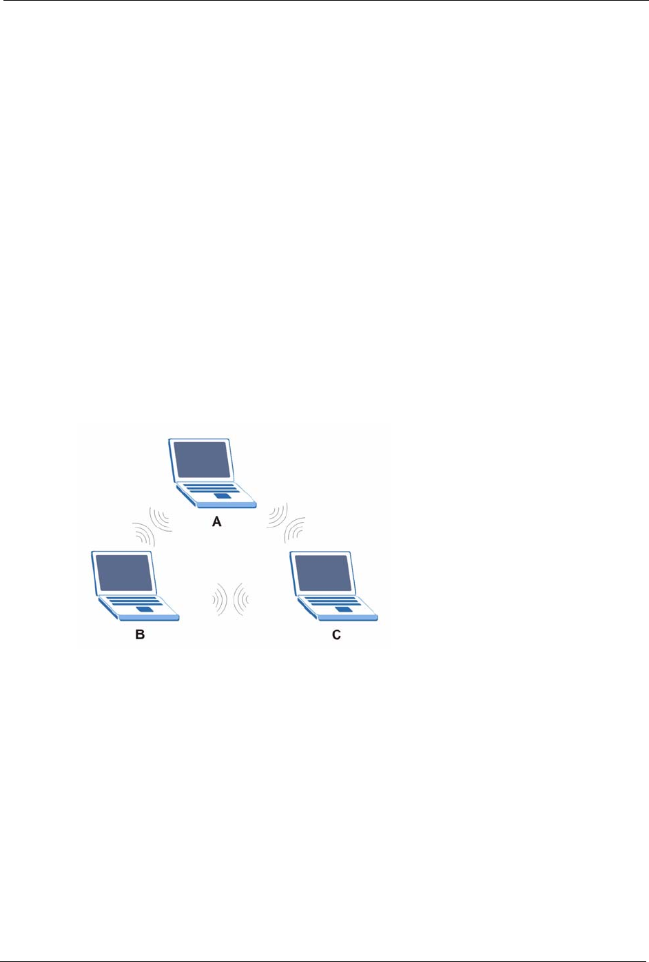
This section discusses ad-hoc and infrastructure wireless LAN topologies.
Ad-hoc Wireless LAN Configuration
The simplest WLAN configuration is an independent (Ad-hoc) WLAN that connects a set of
computers with wireless adapters (A, B, C). Any time two or more wireless adapters are within
range of each other, they can set up an independent network, which is commonly referred to as
an Ad-hoc network or Independent Basic Service Set (IBSS). The following diagram shows an
example of notebook computers using wireless adapters to form an Ad-hoc wireless LAN.
Figure 185 Peer-to-Peer Communication in an Ad-hoc Network
BSS
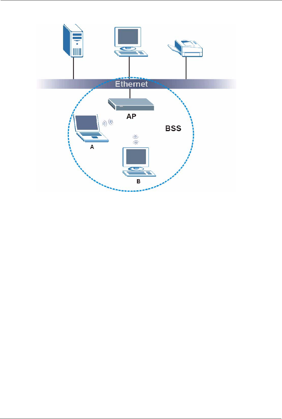
A Basic Service Set (BSS) exists when all communications between wireless clients or
between a wireless client and a wired network client go through one access point (AP).
Intra-BSS traffic is traffic between wireless clients in the BSS. When Intra-BSS is enabled,
wireless client A and B can access the wired network and communicate with each other. When
Intra-BSS is disabled, wireless client A and B can still access the wired network but cannot
communicate with each other.
P-660H/HW-D Series User’s Guide
329 Appendix L Wireless LANs
Figure 186 Basic Service Set
ESS
An Extended Service Set (ESS) consists of a series of overlapping BSSs, each containing an
access point, with each access point connected together by a wired network. This wired
connection between APs is called a Distribution System (DS).
This type of wireless LAN topology is called an Infrastructure WLAN. The Access Points not
only provide communication with the wired network but also mediate wireless network traffic
in the immediate neighborhood.
An ESSID (ESS IDentification) uniquely identifies each ESS. All access points and their
associated wireless clients within the same ESS must have the same ESSID in order to
communicate.

P-660H/HW-D Series User’s Guide
Appendix L Wireless LANs 330
Figure 187 Infrastructure WLAN
Channel
A channel is the radio frequency(ies) used by IEEE 802.11a/b/g wireless devices. Channels
available depend on your geographical area. You may have a choice of channels (for your
region) so you should use a different channel than an adjacent AP (access point) to reduce
interference. Interference occurs when radio signals from different access points overlap
causing interference and degrading performance.
Adjacent channels partially overlap however. To avoid interference due to overlap, your AP
should be on a channel at least five channels away from a channel that an adjacent AP is using.
For example, if your region has 11 channels and an adjacent AP is using channel 1, then you
need to select a channel between 6 or 11.
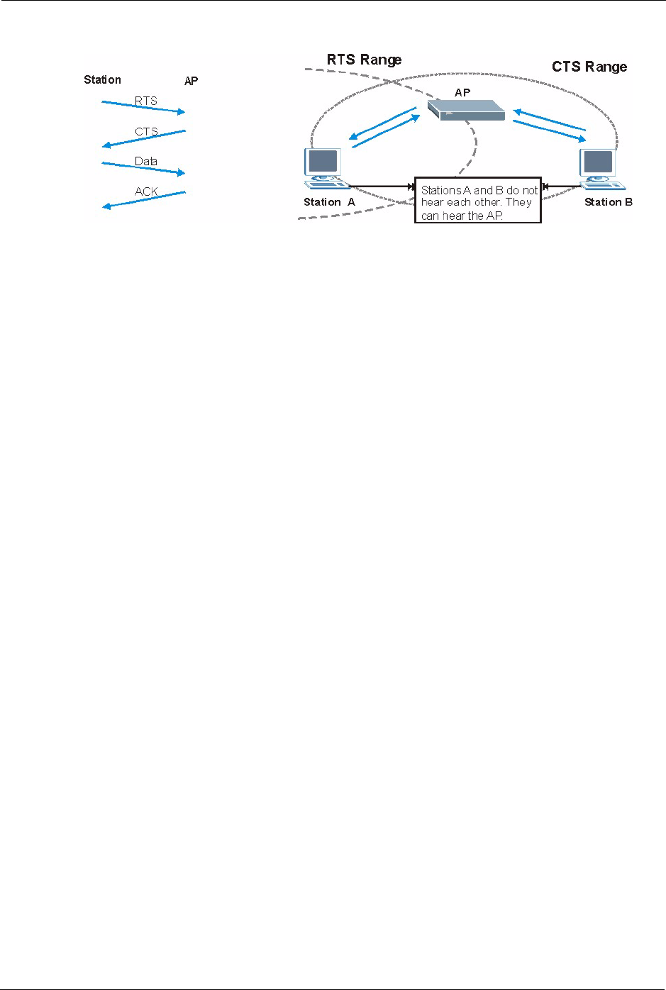
RTS/CTS
A hidden node occurs when two stations are within range of the same access point, but are not
within range of each other. The following figure illustrates a hidden node. Both stations (STA)
are within range of the access point (AP) or wireless gateway, but out-of-range of each other,
so they cannot "hear" each other, that is they do not know if the channel is currently being
used. Therefore, they are considered hidden from each other.
P-660H/HW-D Series User’s Guide
331 Appendix L Wireless LANs
Figure 188 RTS/CTS
When station A sends data to the AP, it might not know that the station B is already using the
channel. If these two stations send data at the same time, collisions may occur when both sets
of data arrive at the AP at the same time, resulting in a loss of messages for both stations.
RTS/CTS is designed to prevent collisions due to hidden nodes. An RTS/CTS defines the
biggest size data frame you can send before an RTS (Request To Send)/CTS (Clear to Send)
handshake is invoked.
When a data frame exceeds the RTS/CTS value you set (between 0 to 2432 bytes), the station
that wants to transmit this frame must first send an RTS (Request To Send) message to the AP
for permission to send it. The AP then responds with a CTS (Clear to Send) message to all
other stations within its range to notify them to defer their transmission. It also reserves and
confirms with the requesting station the time frame for the requested transmission.
Stations can send frames smaller than the specified RTS/CTS directly to the AP without the
RTS (Request To Send)/CTS (Clear to Send) handshake.
You should only configure RTS/CTS if the possibility of hidden nodes exists on your network
and the "cost" of resending large frames is more than the extra network overhead involved in
the RTS (Request To Send)/CTS (Clear to Send) handshake.
If the RTS/CTS value is greater than the Fragmentation Threshold value (see next), then the
RTS (Request To Send)/CTS (Clear to Send) handshake will never occur as data frames will
be fragmented before they reach RTS/CTS size.
Note: Enabling the RTS Threshold causes redundant network overhead that could
negatively affect the throughput performance instead of providing a remedy.
Fragmentation Threshold
A Fragmentation Threshold is the maximum data fragment size (between 256 and 2432
bytes) that can be sent in the wireless network before the AP will fragment the packet into
smaller data frames.

P-660H/HW-D Series User’s Guide
Appendix L Wireless LANs 332
A large Fragmentation Threshold is recommended for networks not prone to interference
while you should set a smaller threshold for busy networks or networks that are prone to
interference.
If the Fragmentation Threshold value is smaller than the RTS/CTS value (see previously)
you set then the RTS (Request To Send)/CTS (Clear to Send) handshake will never occur as
data frames will be fragmented before they reach RTS/CTS size.
Preamble Type
Preamble is used to signal that data is coming to the receiver. Short and Long refer to the
length of the syncronization field in a packet.
Short preamble increases performance as less time sending preamble means more time for
sending data. All IEEE 802.11b/g compliant wireless adapters support long preamble, but not
all support short preamble.
Select Long preamble if you are unsure what preamble mode the wireless adapters support,
and to provide more reliable communications in busy wireless networks.
Select Short preamble if you are sure the wireless adapters support it, and to provide more
efficient communications.
Select Dynamic to have the AP automatically use short preamble when wireless adapters
support it, otherwise the AP uses long preamble.
Note: The AP and the wireless adapters MUST use the same preamble mode in
order to communicate.
IEEE 802.11g Wireless LAN
IEEE 802.11g is fully compatible with the IEEE 802.11b standard. This means an IEEE
802.11b adapter can interface directly with an IEEE 802.11g access point (and vice versa) at
11 Mbps or lower depending on range. IEEE 802.11g has several intermediate rate steps
between the maximum and minimum data rates. The IEEE 802.11g data rate and modulation
are as follows:
Table 150 IEEE 802.11g
DATA RATE (MBPS) MODULATION
1 DBPSK (Differential Binary Phase Shift Keyed)
2 DQPSK (Differential Quadrature Phase Shift Keying)
5.5 / 11 CCK (Complementary Code Keying)
6/9/12/18/24/36/48/54 OFDM (Orthogonal Frequency Division Multiplexing)

P-660H/HW-D Series User’s Guide
333 Appendix L Wireless LANs
Wireless Security Overview
Wireless security is vital to your network to protect wireless communication between wireless
clients, access points and the wired network.
Wireless security methods available on the ZyXEL Device are data encryption, wireless client
authentication, restricting access by device MAC address and hiding the ZyXEL Device
identity.
The following figure shows the relative effectiveness of these wireless security methods
available on your ZyXEL Device.
Note: You must enable the same wireless security settings on the ZyXEL Device and
on all wireless clients that you want to associate with it.
IEEE 802.1x
In June 2001, the IEEE 802.1x standard was designed to extend the features of IEEE 802.11 to
support extended authentication as well as providing additional accounting and control
features. It is supported by Windows XP and a number of network devices. Some advantages
of IEEE 802.1x are:
• User based identification that allows for roaming.
• Support for RADIUS (Remote Authentication Dial In User Service, RFC 2138, 2139) for
centralized user profile and accounting management on a network RADIUS server.
• Support for EAP (Extensible Authentication Protocol, RFC 2486) that allows additional
authentication methods to be deployed with no changes to the access point or the wireless
clients.
Table 151 Wireless Security Levels
Security Level Security Type
Least Secure
Most Secure
Unique SSID (Default)
Unique SSID with Hide SSID Enabled
MAC Address Filtering
WEP Encryption
IEEE802.1x EAP with RADIUS Server Authentication
Wi-Fi Protected Access (WPA)
WPA2

P-660H/HW-D Series User’s Guide
Appendix L Wireless LANs 334
RADIUS
RADIUS is based on a client-server model that supports authentication, authorization and
accounting. The access point is the client and the server is the RADIUS server. The RADIUS
server handles the following tasks:
• Authentication
Determines the identity of the users.
• Authorization
Determines the network services available to authenticated users once they are connected
to the network.
• Accounting
Keeps track of the client’s network activity.
RADIUS is a simple package exchange in which your AP acts as a message relay between the
wireless client and the network RADIUS server.
Types of RADIUS Messages
The following types of RADIUS messages are exchanged between the access point and the
RADIUS server for user authentication:
• Access-Request
Sent by an access point requesting authentication.
• Access-Reject
Sent by a RADIUS server rejecting access.
• Access-Accept
Sent by a RADIUS server allowing access.
• Access-Challenge
Sent by a RADIUS server requesting more information in order to allow access. The
access point sends a proper response from the user and then sends another Access-
Request message.
The following types of RADIUS messages are exchanged between the access point and the
RADIUS server for user accounting:
• Accounting-Request
Sent by the access point requesting accounting.
• Accounting-Response
Sent by the RADIUS server to indicate that it has started or stopped accounting.

P-660H/HW-D Series User’s Guide
335 Appendix L Wireless LANs
In order to ensure network security, the access point and the RADIUS server use a shared
secret key, which is a password, they both know. The key is not sent over the network. In
addition to the shared key, password information exchanged is also encrypted to protect the
network from unauthorized access.
Types of Authentication
This section discusses some popular authentication types: EAP-MD5, EAP-TLS, EAP-
TTLS, PEAP and LEAP.
The type of authentication you use depends on the RADIUS server or the AP. Consult your
network administrator for more information.
EAP-MD5 (Message-Digest Algorithm 5)
MD5 authentication is the simplest one-way authentication method. The authentication server
sends a challenge to the wireless client. The wireless client ‘proves’ that it knows the password
by encrypting the password with the challenge and sends back the information. Password is
not sent in plain text.
However, MD5 authentication has some weaknesses. Since the authentication server needs to
get the plaintext passwords, the passwords must be stored. Thus someone other than the
authentication server may access the password file. In addition, it is possible to impersonate an
authentication server as MD5 authentication method does not perform mutual authentication.
Finally, MD5 authentication method does not support data encryption with dynamic session
key. You must configure WEP encryption keys for data encryption.
EAP-TLS (Transport Layer Security)
With EAP-TLS, digital certifications are needed by both the server and the wireless clients for
mutual authentication. The server presents a certificate to the client. After validating the
identity of the server, the client sends a different certificate to the server. The exchange of
certificates is done in the open before a secured tunnel is created. This makes user identity
vulnerable to passive attacks. A digital certificate is an electronic ID card that authenticates the
sender’s identity. However, to implement EAP-TLS, you need a Certificate Authority (CA) to
handle certificates, which imposes a management overhead.
EAP-TTLS (Tunneled Transport Layer Service)
EAP-TTLS is an extension of the EAP-TLS authentication that uses certificates for only the
server-side authentications to establish a secure connection. Client authentication is then done
by sending username and password through the secure connection, thus client identity is
protected. For client authentication, EAP-TTLS supports EAP methods and legacy
authentication methods such as PAP, CHAP, MS-CHAP and MS-CHAP v2.

P-660H/HW-D Series User’s Guide
Appendix L Wireless LANs 336
PEAP (Protected EAP)
Like EAP-TTLS, server-side certificate authentication is used to establish a secure connection,
then use simple username and password methods through the secured connection to
authenticate the clients, thus hiding client identity. However, PEAP only supports EAP
methods, such as EAP-MD5, EAP-MSCHAPv2 and EAP-GTC (EAP-Generic Token Card),
for client authentication. EAP-GTC is implemented only by Cisco.
LEAP
LEAP (Lightweight Extensible Authentication Protocol) is a Cisco implementation of IEEE
802.1x.
Dynamic WEP Key Exchange
The AP maps a unique key that is generated with the RADIUS server. This key expires when
the wireless connection times out, disconnects or reauthentication times out. A new WEP key
is generated each time reauthentication is performed.
If this feature is enabled, it is not necessary to configure a default encryption key in the
Wireless screen. You may still configure and store keys here, but they will not be used while
Dynamic WEP is enabled.
Note: EAP-MD5 cannot be used with Dynamic WEP Key Exchange
For added security, certificate-based authentications (EAP-TLS, EAP-TTLS and PEAP) use
dynamic keys for data encryption. They are often deployed in corporate environments, but for
public deployment, a simple user name and password pair is more practical. The following
table is a comparison of the features of authentication types.
Table 152 Comparison of EAP Authentication Types
EAP-MD5 EAP-TLS EAP-TTLS PEAP LEAP
Mutual Authentication No Yes Yes Yes Yes
Certificate – Client No Yes Optional Optional No
Certificate – Server No Yes Yes Yes No
Dynamic Key Exchange No Yes Yes Yes Yes
Credential Integrity None Strong Strong Strong Moderate
Deployment Difficulty Easy Hard Moderate Moderate Moderate
Client Identity Protection No No Yes Yes No

P-660H/HW-D Series User’s Guide
337 Appendix L Wireless LANs
WPA and WPA2
Wi-Fi Protected Access (WPA) is a subset of the IEEE 802.11i standard. WPA2 (IEEE
802.11i) is a wireless security standard that defines stronger encryption, authentication and
key management than WPA.
Key differences between WPA or WPA2 and WEP are improved data encryption and user
authentication.
If both an AP and the wireless clients support WPA2 and you have an external RADIUS
server, use WPA2 for stronger data encryption. If you don't have an external RADIUS server,
you should use WPA2-PSK (WPA2-Pre-Shared Key) that only requires a single (identical)
password entered into each access point, wireless gateway and wireless client. As long as the
passwords match, a wireless client will be granted access to a WLAN.
If the AP or the wireless clients do not support WPA2, just use WPA or WPA-PSK depending
on whether you have an external RADIUS server or not.
Select WEP only when the AP and/or wireless clients do not support WPA or WPA2. WEP is
less secure than WPA or WPA2.
Encryption
Both WPA and WPA2 improve data encryption by using Temporal Key Integrity Protocol
(TKIP), Message Integrity Check (MIC) and IEEE 802.1x. WPA and WPA2 use Advanced
Encryption Standard (AES) in the Counter mode with Cipher block chaining Message
authentication code Protocol (CCMP) to offer stronger encryption than TKIP.
TKIP uses 128-bit keys that are dynamically generated and distributed by the authentication
server. AES (Advanced Encryption Standard) is a block cipher that uses a 256-bit
mathematical algorithm called Rijndael. They both include a per-packet key mixing function,
a Message Integrity Check (MIC) named Michael, an extended initialization vector (IV) with
sequencing rules, and a re-keying mechanism.
WPA and WPA2 regularly change and rotate the encryption keys so that the same encryption
key is never used twice.
The RADIUS server distributes a Pairwise Master Key (PMK) key to the AP that then sets up
a key hierarchy and management system, using the PMK to dynamically generate unique data
encryption keys to encrypt every data packet that is wirelessly communicated between the AP
and the wireless clients. This all happens in the background automatically.
The Message Integrity Check (MIC) is designed to prevent an attacker from capturing data
packets, altering them and resending them. The MIC provides a strong mathematical function
in which the receiver and the transmitter each compute and then compare the MIC. If they do
not match, it is assumed that the data has been tampered with and the packet is dropped.

P-660H/HW-D Series User’s Guide
Appendix L Wireless LANs 338
By generating unique data encryption keys for every data packet and by creating an integrity
checking mechanism (MIC), with TKIP and AES it is more difficult to decrypt data on a Wi-Fi
network than WEP and difficult for an intruder to break into the network.
The encryption mechanisms used for WPA(2) and WPA(2)-PSK are the same. The only
difference between the two is that WPA(2)-PSK uses a simple common password, instead of
user-specific credentials. The common-password approach makes WPA(2)-PSK susceptible to
brute-force password-guessing attacks but it’s still an improvement over WEP as it employs a
consistent, single, alphanumeric password to derive a PMK which is used to generate unique
temporal encryption keys. This prevent all wireless devices sharing the same encryption keys.
(a weakness of WEP)
User Authentication
WPA and WPA2 apply IEEE 802.1x and Extensible Authentication Protocol (EAP) to
authenticate wireless clients using an external RADIUS database. WPA2 reduces the number
of key exchange messages from six to four (CCMP 4-way handshake) and shortens the time
required to connect to a network. Other WPA2 authentication features that are different from
WPA include key caching and pre-authentication. These two features are optional and may not
be supported in all wireless devices.
Key caching allows a wireless client to store the PMK it derived through a successful
authentication with an AP. The wireless client uses the PMK when it tries to connect to the
same AP and does not need to go with the authentication process again.
Pre-authentication enables fast roaming by allowing the wireless client (already connecting to
an AP) to perform IEEE 802.1x authentication with another AP before connecting to it.
Wireless Client WPA Supplicants
A wireless client supplicant is the software that runs on an operating system instructing the
wireless client how to use WPA. At the time of writing, the most widely available supplicant is
the WPA patch for Windows XP, Funk Software's Odyssey client.
The Windows XP patch is a free download that adds WPA capability to Windows XP's built-
in "Zero Configuration" wireless client. However, you must run Windows XP to use it.
WPA(2) with RADIUS Application Example
You need the IP address of the RADIUS server, its port number (default is 1812), and the
RADIUS shared secret. A WPA(2) application example with an external RADIUS server
looks as follows. "A" is the RADIUS server. "DS" is the distribution system.
1The AP passes the wireless client's authentication request to the RADIUS server.
2The RADIUS server then checks the user's identification against its database and grants
or denies network access accordingly.
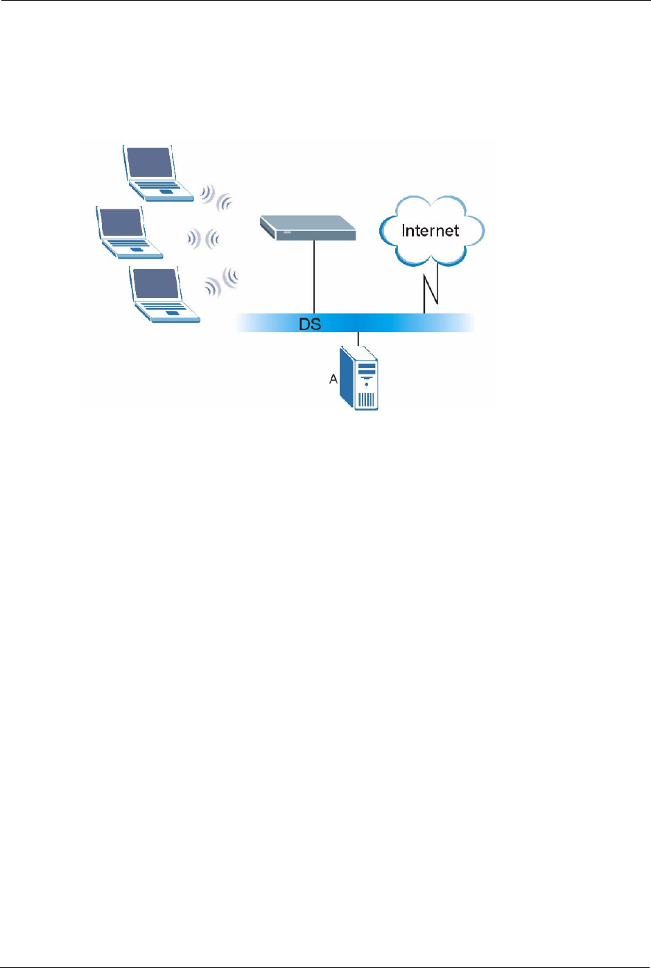
P-660H/HW-D Series User’s Guide
339 Appendix L Wireless LANs
3The RADIUS server distributes a Pairwise Master Key (PMK) key to the AP that then
sets up a key hierarchy and management system, using the pair-wise key to dynamically
generate unique data encryption keys to encrypt every data packet that is wirelessly
communicated between the AP and the wireless clients.
Figure 189 WPA(2) with RADIUS Application Example
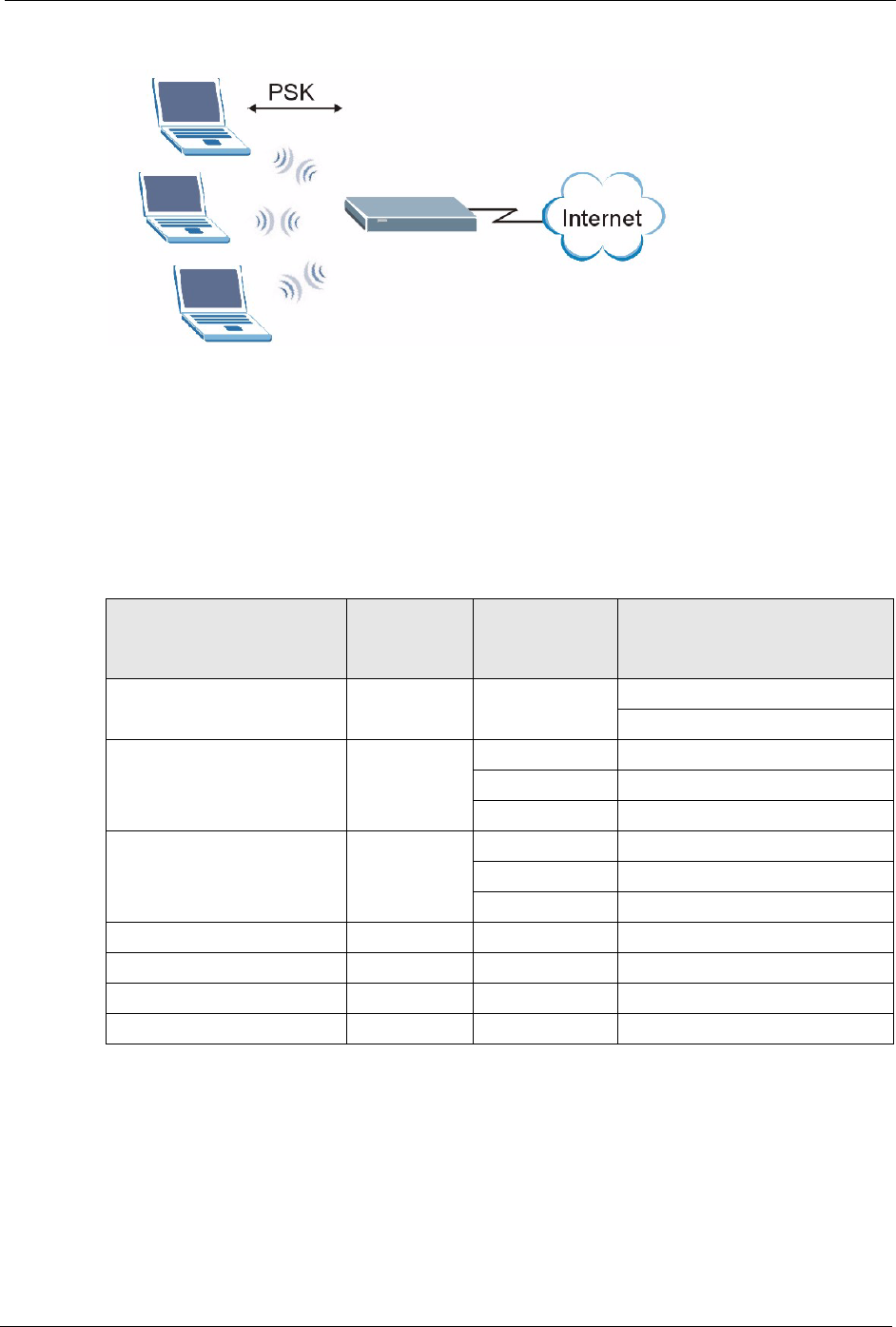
21.4.2 WPA(2)-PSK Application Example
A WPA(2)-PSK application looks as follows.
1First enter identical passwords into the AP and all wireless clients. The Pre-Shared Key
(PSK) must consist of between 8 and 63 ASCII characters or 64 hexadecimal characters
(including spaces and symbols).
2The AP checks each wireless client's password and (only) allows it to join the network if
the password matches.
3The AP and wireless clients use the pre-shared key to generate a common PMK (Pairwise
Master Key).
4The AP and wireless clients use the TKIP or AES encryption process to encrypt data
exchanged between them.
P-660H/HW-D Series User’s Guide
Appendix L Wireless LANs 340
Figure 190 WPA(2)-PSK Authentication
Security Parameters Summary
Refer to this table to see what other security parameters you should configure for each
Authentication Method/ key management protocol type. MAC address filters are not
dependent on how you configure these security features.
Table 153 Wireless Security Relational Matrix
AUTHENTICATION
METHOD/ KEY
MANAGEMENT PROTOCOL
ENCRYPTION
METHOD
ENTER
MANUAL KEY IEEE 802.1X
Open None No Disable
Enable without Dynamic WEP Key
Open WEP No Enable with Dynamic WEP Key
Yes Enable without Dynamic WEP Key
Yes Disable
Shared WEP No Enable with Dynamic WEP Key
Yes Enable without Dynamic WEP Key
Yes Disable
WPA TKIP/AES No Enable
WPA-PSK TKIP/AES Yes Disable
WPA2 TKIP/AES No Enable
WPA2-PSK TKIP/AES Yes Disable

P-660H/HW-D Series User’s Guide
341 Appendix L Wireless LANs
P-660H/HW-D Series User’s Guide
Appendix M Pop-up Windows, JavaScripts and Java Permissions 342
APPENDIX M
Pop-up Windows, JavaScripts and Java
Permissions
In order to use the web configurator you need to allow:
• Web browser pop-up windows from your device.
• JavaScripts (enabled by default).
• Java permissions (enabled by default).
Note: Internet Explorer 6 screens are used here. Screens for other Internet Explorer
versions may vary.
Internet Explorer Pop-up Blockers
You may have to disable pop-up blocking to log into your device.
Either disable pop-up blocking (enabled by default in Windows XP SP (Service Pack) 2) or
allow pop-up blocking and create an exception for your device’s IP address.
Disable pop-up Blockers
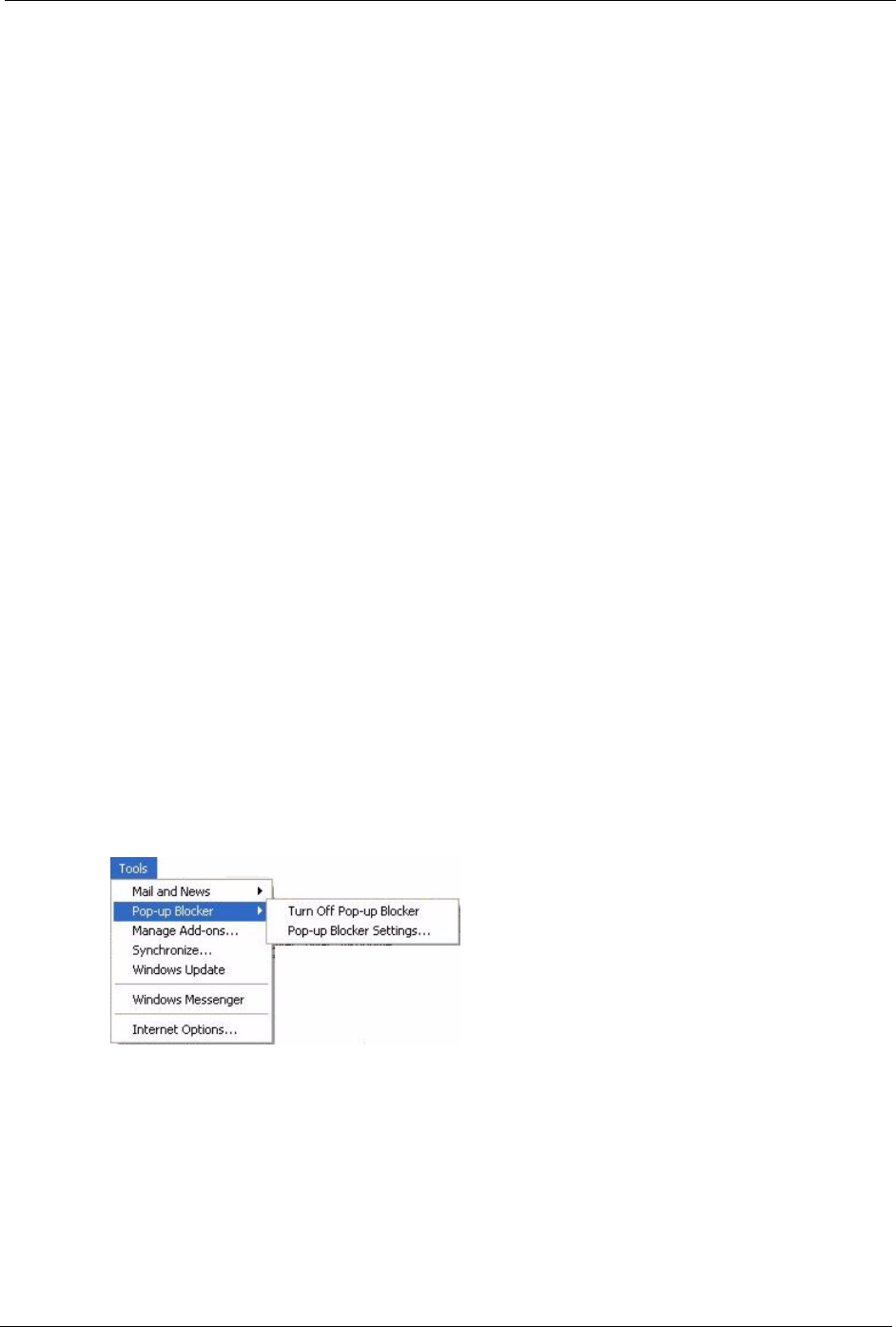
1In Internet Explorer, select Too ls , Pop-up Blocker and then select Turn Off Pop-up
Blocker.
Figure 191 Pop-up Blocker
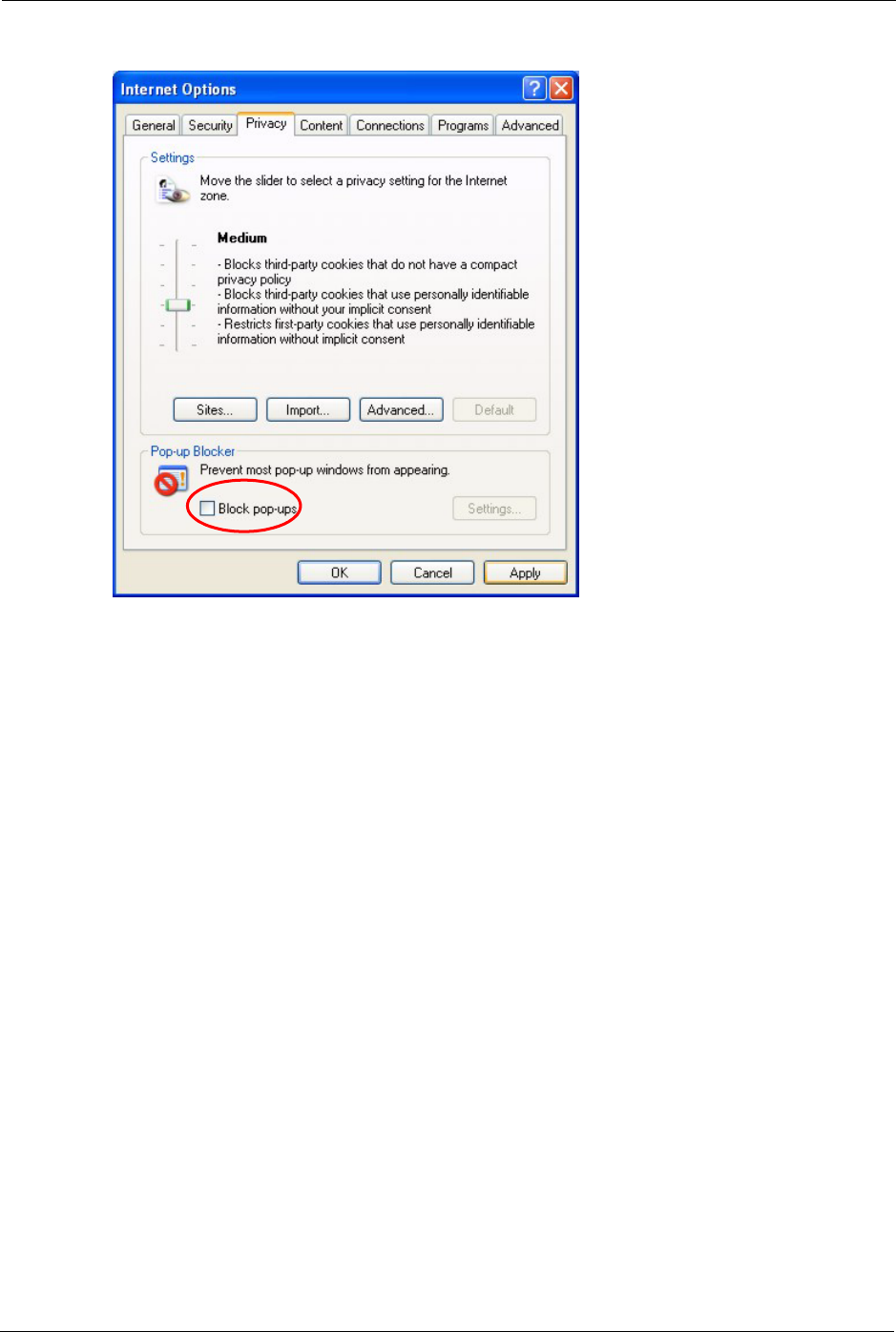
You can also check if pop-up blocking is disabled in the Pop-up Blocker section in the
Privacy tab.
1In Internet Explorer, select Too ls , Internet Options, Privacy.
2Clear the Block pop-ups check box in the Pop-up Blocker section of the screen. This
disables any web pop-up blockers you may have enabled.
P-660H/HW-D Series User’s Guide
343 Appendix M Pop-up Windows, JavaScripts and Java Permissions
Figure 192 Internet Options
3Click Apply to save this setting.
Enable pop-up Blockers with Exceptions
Alternatively, if you only want to allow pop-up windows from your device, see the following
steps.
1In Internet Explorer, select Too ls , Internet Options and then the Privacy tab.
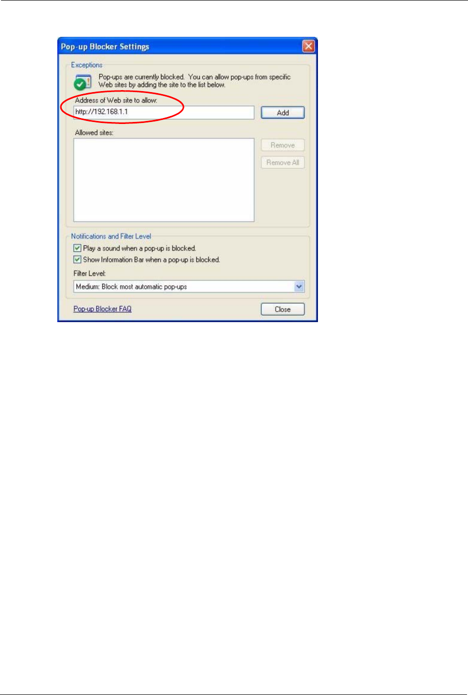
2Select Settings…to open the Pop-up Blocker Settings screen.
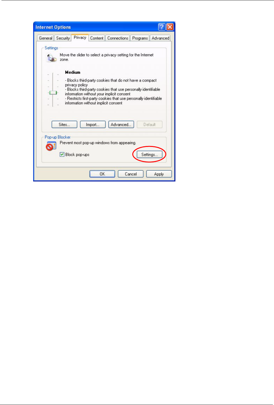
P-660H/HW-D Series User’s Guide
Appendix M Pop-up Windows, JavaScripts and Java Permissions 344
Figure 193 Internet Options
3Type the IP address of your device (the web page that you do not want to have blocked)
with the prefix “http://”. For example, http://192.168.1.1.
4Click Add to move the IP address to the list of Allowed sites.
P-660H/HW-D Series User’s Guide
345 Appendix M Pop-up Windows, JavaScripts and Java Permissions
Figure 194 Pop-up Blocker Settings
5Click Close to return to the Privacy screen.
6Click Apply to save this setting.
JavaScripts
If pages of the web configurator do not display properly in Internet Explorer, check that
JavaScripts are allowed.
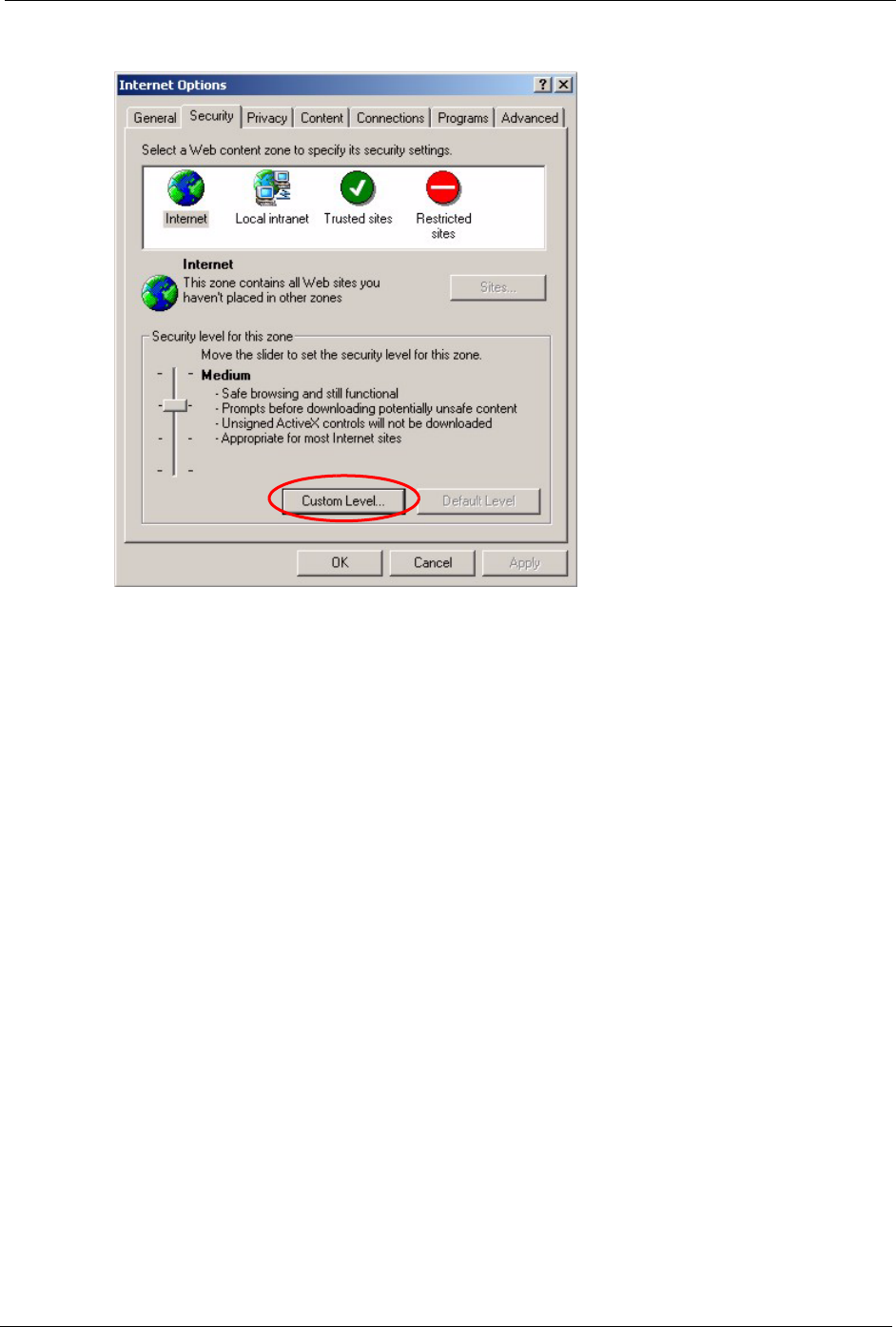
1In Internet Explorer, click Tools, Internet Options and then the Security tab.
P-660H/HW-D Series User’s Guide
Appendix M Pop-up Windows, JavaScripts and Java Permissions 346
Figure 195 Internet Options
2Click the Custom Level... button.
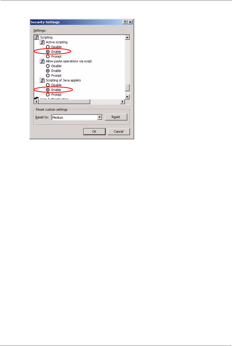
3Scroll down to Scripting.
4Under Active scripting make sure that Enable is selected (the default).
5Under Scripting of Java applets make sure that Enable is selected (the default).
6Click OK to close the window.
P-660H/HW-D Series User’s Guide
347 Appendix M Pop-up Windows, JavaScripts and Java Permissions
Figure 196 Security Settings - Java Scripting
Java Permissions
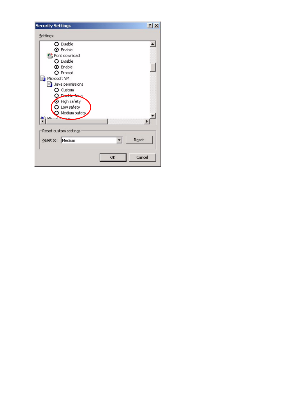
1From Internet Explorer, click Tools, Internet Options and then the Security tab.
2Click the Custom Level... button.
3Scroll down to Microsoft VM.
4Under Java permissions make sure that a safety level is selected.
5Click OK to close the window.
P-660H/HW-D Series User’s Guide
Appendix M Pop-up Windows, JavaScripts and Java Permissions 348
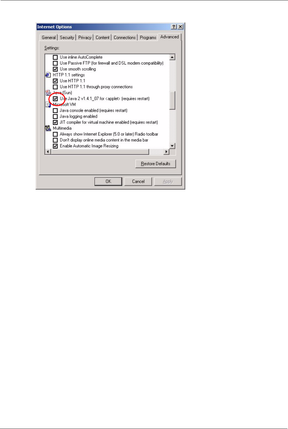
Figure 197 Security Settings - Java
JAVA (Sun)
1From Internet Explorer, click Tools, Internet Options and then the Advanced tab.
2make sure that Use Java 2 for <applet> under Java (Sun) is selected.
3Click OK to close the window.
P-660H/HW-D Series User’s Guide
349 Appendix M Pop-up Windows, JavaScripts and Java Permissions
Figure 198 Java (Sun)
P-660H/HW-D Series User’s Guide
Appendix N Triangle Route 350
APPENDIX N
Triangle Route
The Ideal Setup
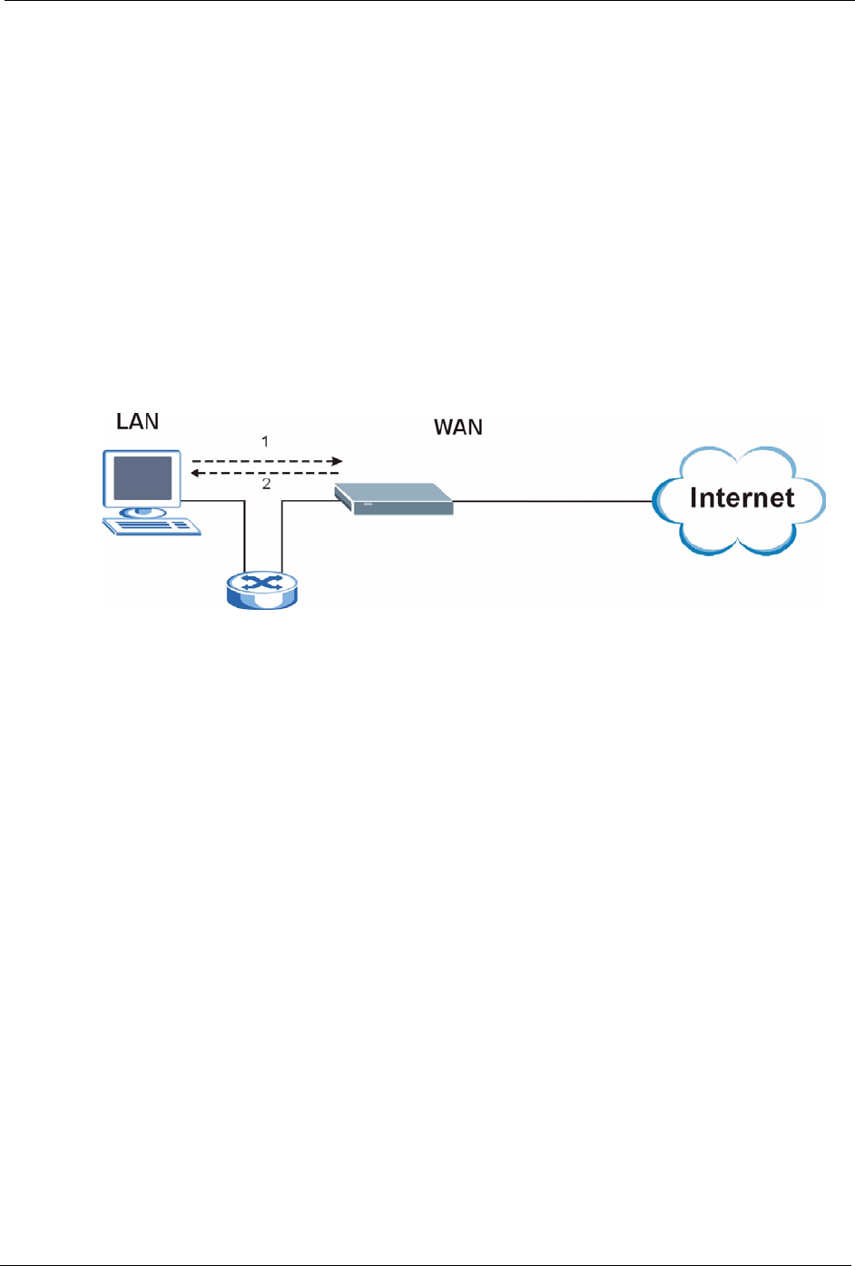
When the firewall is on, your ZyXEL Device acts as a secure gateway between your LAN and
the Internet. In an ideal network topology, all incoming and outgoing network traffic passes
through the ZyXEL Device to protect your LAN against attacks.
Figure 199 Ideal Setup
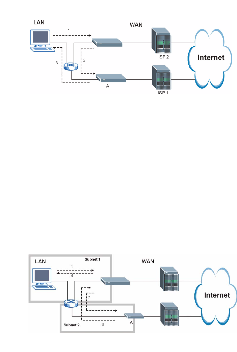
The “Triangle Route” Problem
A traffic route is a path for sending or receiving data packets between two Ethernet devices.
Some companies have more than one route to one or more ISPs. If the alternate gateway is on
the LAN (and it’s IP address is in the same subnet), the “triangle route” problem may occur.
The steps below describe the “triangle route” problem.
1A computer on the LAN initiates a connection by sending out a SYN packet to a
receiving server on the WAN.
2The ZyXEL Device reroutes the SYN packet through Gateway A on the LAN to the
WA N.
3The reply from the WAN goes directly to the computer on the LAN without going
through the ZyXEL Device.
As a result, the ZyXEL Device resets the connection, as the connection has not been
acknowledged.
P-660H/HW-D Series User’s Guide
351 Appendix N Triangle Route
Figure 200 “Triangle Route” Problem
The “Triangle Route” Solutions
This section presents you two solutions to the “triangle route” problem.
IP Aliasing
IP alias allows you to partition your network into logical sections over the same Ethernet
interface. Your ZyXEL Device supports up to three logical LAN interfaces with the ZyXEL
Device being the gateway for each logical network. By putting your LAN and Gateway B in
different subnets, all returning network traffic must pass through the ZyXEL Device to your
LAN. The following steps describe such a scenario.
1A computer on the LAN initiates a connection by sending a SYN packet to a receiving
server on the WAN.
2The ZyXEL Device reroutes the packet to Gateway A, which is in Subnet 2.
3The reply from WAN goes through the ZyXEL Device to the computer on the LAN in
Subnet 1.
Figure 201 IP Alias

P-660H/HW-D Series User’s Guide
Index 352
Index
A
access point 108
access point. See also AP.
Address Assignment 96
Address Resolution Protocol (ARP) 99
ADSL standards 35
Advanced Encryption Standard 337
alternative subnet mask notation 292
Antenna gain 119
Any IP 35, 98
How it works 99
note 99
Any IP Setup 101
AP 108
AP (access point) 330
AP. See also access point.
Application-level Firewalls 145
applications
Internet access 39
ATM Adaptation Layer 5 (AAL5) 77
Attack Alert 175
Attack Types 149
B
Backup 240
Backup Type 92
Bandwidth Management 186
Bandwidth Manager Class Configuration 192
Bandwidth Manager Monitor 196
Bandwidth Manager Summary 191
Basic wireless security 67
Blocking Time 174
Brute-force Attack, 148
BSS 328
BW Budget 193
C
CA 335
CBR (Continuous Bit Rate) 85, 89
Certificate Authority 335
certifications
Notices 4
viewing 4
change password at login 43
Channel 330
Interference 330
channel 108
Channel ID 112
compact 37
compact guide 42
Configuration 95
Content Filtering 178
Categories 178
Schedule 179
Trusted computers 180
URL keyword blocking 178
Content filtering 178
content filtering 36
Copyright 2
CTS (Clear to Send) 331
Custom Ports
Creating/Editing 166
Customer Support 8
Customized Services 165
Customized services 165
D
Default 242
default LAN IP address 42
Denial of Service 145, 146, 174
Destination Address 158
device model number 238
DHCP 37, 95, 96, 198, 226
DHCP client 37
DHCP relay 37
DHCP server 37
diagnostic 244
disclaimer 2
DNS 209
Domain Name 96, 137, 226
Domain Name System 95

P-660H/HW-D Series User’s Guide
353 Index
DoS 146
Basics 146
Types 147
DoS (Denial of Service) 35
DoS attacks, types of 147
DSL (Digital Subscriber Line) 254
DSL line, reinitialize 245
DSLAM (Digital Subscriber Line Access Multiplexer) 39
Dynamic DNS 36, 198
dynamic DNS 36
Dynamic Host Configuration Protocol 37
Dynamic WEP Key Exchange 336
DYNDNS Wildcard 198
E
EAP Authentication 335
ECHO 137
E-Mail 131
E-mail
Log Example 236
embedded help 45
Encapsulated Routing Link Protocol (ENET ENCAP) 76
Encapsulation 76, 77
ENET ENCAP 76
PPP over Ethernet 76
PPPoA 77
RFC 1483 77
Encryption 337
encryption 110
and local (user) database 111
key 111
WPA compatible 111
ESS 329
Ethernet 251
Extended Service Set 329
Extended Service Set IDentification 112
Extended wireless security 66
F
Fairness-based Scheduler 188
FCC interference statement 3
Federal Communications Commission 3
Finger 137
Firewall
Access Methods 156
Address Type 164
Alerts 159
Anti-Probing 172
Creating/Editing Rules 162
Custom Ports 165
Enabling 159
Firewall Vs Filters 154
Guidelines For Enhancing Security 153
Introduction 145
LAN to WAN Rules 159
Policies 156
Rule Checklist 157
Rule Logic 157
Rule Security Ramifications 157
Services 170
Types 144
When To Use 155
firmware 238
upgrade 238
upload 238
upload error 239
Fragmentation Threshold 331
Fragmentation threshold 331
FTP 136, 137, 202, 205
FTP Restrictions 202
Full Rate 308
G
General Setup 226
General wireless LAN screen 112
H
Half-Open Sessions 174
Hidden node 330
hide SSID 109
Host 227, 228
HTTP 137, 145, 146, 147
HTTP (Hypertext Transfer Protocol) 238
I
IANA 97
IANA (Internet Assigned Number Authority) 165
IBSS 328
ICMP echo 148
IEEE 802.11g 37, 332

P-660H/HW-D Series User’s Guide
Index 354
IEEE 802.11i 38
IGMP 98
Independent Basic Service Set 328
initialization vector (IV) 337
Install UPnP 216
Windows Me 216
Windows XP 218
Integrated Services Digital Network 34
Internal SPTGEN 256
FTP Upload Example 258
Points to Remember 257
Text File 256
Internet Access 35, 39
Internet access 56
Internet Access Setup 247
Internet access wizard setup 56
Internet Assigned Numbers AuthoritySee IANA 97
Internet Control Message Protocol (ICMP) 148, 172
IP Address 96, 137, 138, 139
IP Address Assignment 78
ENET ENCAP 79
PPPoA or PPPoE 78
RFC 1483 78
IP alias 37
IP Pool 102
IP Pool Setup 95
IP protocol type 170
IP Spoofing 147, 150
ISDN (Integrated Services Digital Network) 34
K
Key Fields For Configuring Rules 158
L
LAN Setup 76, 94
LAN TCP/IP 96
LAN to WAN Rules 159
LAND 147, 148
local (user) database 110
and encryption 111
Logs 232
M
MAC address 109
MAC address filter 109
MAC Address Filter Action 125
MAC Address Filtering 124
MAC Filter 124
Management Information Base (MIB) 207
Maximize Bandwidth Usage 188
Maximum Burst Size (MBS) 80, 85, 90
Max-incomplete High 174
Max-incomplete Low 174
Media Bandwidth Management 36
Message Integrity Check (MIC) 337
Metric 79
Multicast 98
Multiplexing 77
multiplexing 77
LLC-based 77
VC-based 77
Multiprotocol Encapsulation 77
N
Nailed-Up Connection 79
NAT 96, 137, 138
Address mapping rule 142
Application 134
Definitions 132
How it works 133
Mapping Types 134
What it does 133
What NAT does 133
NAT (Network Address Translation) 132
NAT mode 136
NAT Traversal 214
navigating the web configurator 44
NetBIOS commands 149
Network Address Translation (NAT) 36
Network Management 137
NNTP 137
O
One-Minute High 174

P-660H/HW-D Series User’s Guide
355 Index
P
Packet Filtering 154
Packet filtering
When to use 155
Packet Filtering Firewalls 144
Pairwise Master Key (PMK) 337, 339
Peak Cell Rate (PCR) 80, 85, 90
Ping of Death 147
Point to Point Protocol over ATM Adaptation Layer 5
(AAL5) 77
Point-to-Point 254
Point-to-Point Tunneling Protocol 137
POP3 137, 146, 147
PPPoA 78
PPPoE 76
Benefits 76
PPPoE (Point-to-Point Protocol over Ethernet) 36
PPTP 137
Preamble Mode 332
Priorities 126, 190
Priority 193
Priority-based Scheduler 187
product registration 7
Q
QoS 111
benefits 111
Quick Start Guide 32
R
RADIUS 334
Shared Secret Key 335
RADIUS Message Types 334
RADIUS Messages 334
RADIUS server 110
registration
product 7
reinitialize the ADSL line 245
Related Documentation 32
Remote Management and NAT 203
Remote Management Limitations 202
Reset button, the 44
Resetting the ZyXEL device 44
Restore 241
RF (Radio Frequency) 37
RFC 1483 77
RFC 1631 132
RFC-1483 78
RFC-2364 78
RFC2516 36
RIPSee Routing Information Protocol 97
Routing Information Protocol 97
Direction 97
Version 97
RTS (Request To Send) 331
RTS Threshold 330, 331
Rules 159
Checklist 157
Key Fields 158
LAN to WAN 159
Logic 157
Predefined Services 170
S
Safety Warnings 5
Saving the State 150
Scheduler 187
Security In General 153
Security Parameters 340
Security Ramifications 157
Server 134, 135, 229
Service 158
Service Set 112
Service Set IDentity. See SSID.
Service Type 166, 247
Services 137
SMTP 137
Smurf 148, 149
SNMP 137, 206
Manager 207
MIBs 207
Source Address 158
Splitters 308
SSID 108
hide 109
Stateful Inspection 35, 144, 145, 150
Process 151
ZyXEL device 151
Static Route 182
SUA 135
SUA (Single User Account) 135
SUA vs NAT 135
subnet 290

P-660H/HW-D Series User’s Guide
Index 356
Subnet Mask 96, 164
subnet mask 292
subnetting 292
Supporting Disk 32
Sustain Cell Rate (SCR) 85, 90
Sustained Cell Rate (SCR) 80
SYN Flood 147, 148
SYN-ACK 148
Syntax Conventions 32
Syslog 169
System Name 227
System Parameter Table Generator 256
System Timeout 203
T
TCP Maximum Incomplete 174, 175
TCP Security 152
TCP/IP 146, 147
Teardrop 147
Tel ne t 204
Temporal Key Integrity Protocol (TKIP) 337
Text File Format 256
TFTP Restrictions 202
Three-Way Handshake 147
Threshold Values 173
TMM QoS. See also QoS.
Traceroute 150
trademarks 2
Traffic Redirect 90, 91
Traffic redirect 90, 92
traffic redirect 36
Traffic shaping 80
Triangle 350
Triangle Route Solutions 351
U
UBR (Unspecified Bit Rate) 85, 89
UDP/ICMP Security 152
Universal Plug and Play 214
Application 214
Security issues 215
Universal Plug and Play (UPnP) 36
UPnP 214
Forum 215
Upper Layer Protocols 152, 153
User Authentication 338
user authentication 110
local (user) database 110
RADIUS server 110
weaknesses 110
User Name 199
V
VBR (Variable Bit Rate) 85, 89
VC-based Multiplexing 78
Virtual Channel Identifier (VCI) 78
virtual circuit (VC) 77
Virtual Path Identifier (VPI) 78
VPI & VCI 78
W
WAN (Wide Area Network) 76
WAN backup 91
WAN to LAN Rules 159
warranty
note 7
Web 203
Web Configurator 42, 44, 45, 153, 158
web configurator screen summary 45
WEP (Wired Equivalent Privacy) 38
WEP Encryption 116
WEP encryption 114
Wi-Fi Multimedia QoS 126
Wi-Fi Protected Access 337
Wi-Fi Protected Access (WPA) 38
wireless client 108
Wireless Client WPA Supplicants 338
Wireless LAN MAC Address Filtering 38
wireless network 108
basic guidelines 108
wireless networks
channel 108
encryption 110
MAC address filter 109
security 109
SSID 108
Wireless security 333
wireless security 109
WLAN
Interference 330
