ZyXEL Communications P660HWD1V2 802.11g WIRELESS ADSL2+ 4-PORT GATEWAY User Manual P 660H HW W T Series V3 40 User s Guide
ZyXEL Communications Corporation 802.11g WIRELESS ADSL2+ 4-PORT GATEWAY P 660H HW W T Series V3 40 User s Guide
Contents
users manual 3
P-660H/HW-D Series User’s Guide
Chapter 7 Wireless LAN 114
7.4.2 WEP Encryption
WEP encryption scrambles the data transmitted between the wireless clients and the access
points to keep network communications private. It encrypts unicast and multicast
communications in a network. Both the wireless clients and the access points must use the
same WEP key.
Your ZyXEL Device allows you to configure up to four 64-bit, 128-bit or 256-bit WEP keys
but only one key can be enabled at any one time.
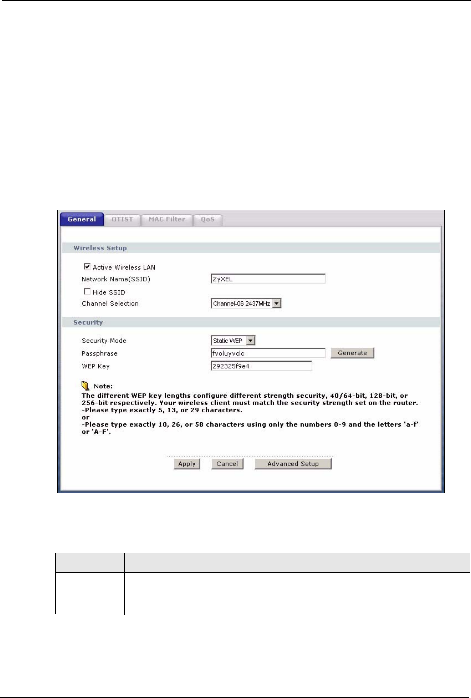
In order to configure and enable WEP encryption; click Network > Wireless LAN to display
the General screen. Select Static WEP from the Security Mode list.
Figure 59 Wireless: Static WEP Encryption
The following table describes the wireless LAN security labels in this screen.
Table 34 Wireless: Static WEP Encryption
LABEL DESCRIPTION
Security Mode Choose Static WEP from the drop-down list box.
Passphrase Enter a Passphrase (up to 32 printable characters) and clicking Generate. The ZyXEL
Device automatically generates a WEP key.
P-660H/HW-D Series User’s Guide
115 Chapter 7 Wireless LAN
7.4.3 WPA-PSK/WPA2-PSK
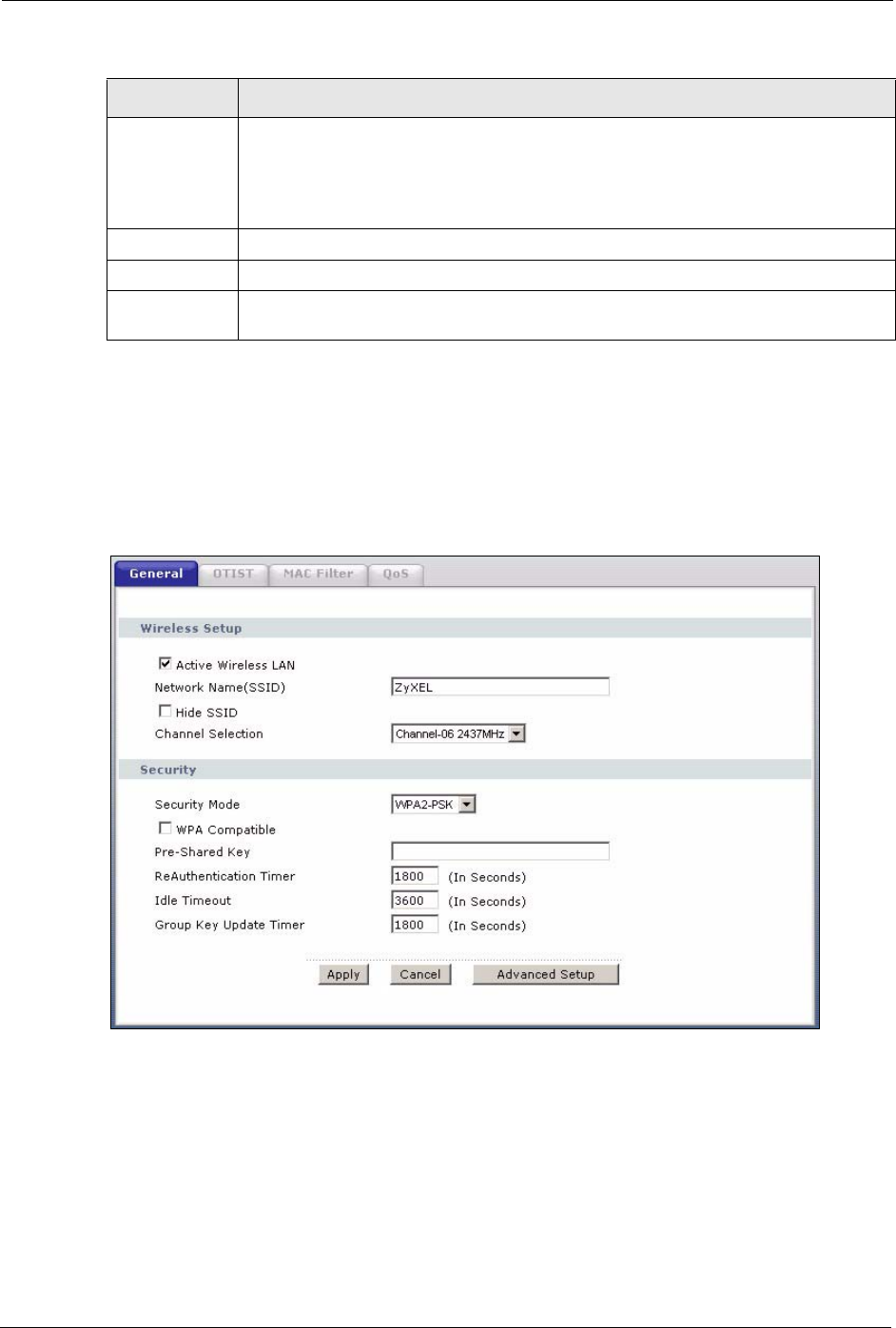
In order to configure and enable WPA(2)-PSK authentication; click Network > Wireless
LAN to display the General screen. Select WPA-PSK or WPA2-PSK from the Security
Mode list.
Figure 60 Wireless: WPA-PSK/WPA2-PSK
WEP Key The WEP keys are used to encrypt data. Both the ZyXEL Device and the wireless
clients must use the same WEP key for data transmission.
If you want to manually set the WEP key, enter any 5, 13 or 29 characters (ASCII
string) or 10, 26 or 58 hexadecimal characters ("0-9", "A-F") for a 64-bit, 128-bit or
256-bit WEP key respectively.
Apply Click Apply to save your changes back to the ZyXEL Device.
Cancel Click Cancel to reload the previous configuration for this screen.
Advanced
Setup
Click Advanced Setup to display the Wireless Advanced Setup screen and edit
more details of your WLAN setup.
Table 34 Wireless: Static WEP Encryption
LABEL DESCRIPTION

P-660H/HW-D Series User’s Guide
Chapter 7 Wireless LAN 116
The following table describes the wireless LAN security labels in this screen.
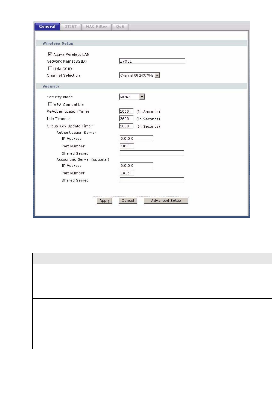
7.4.4 WPA/WPA2
In order to configure and enable WPA/WPA2; click the Wireless LAN link under Network to
display the General screen. Select WPA or WPA2 from the Security Mode list.
Table 35 Wireless: WPA-PSK/WPA2-PSK
LABEL DESCRIPTION
Security Mode Choose WPA-PSK or WPA2-PSK from the drop-down list box.
WPA Compatible This check box is available only when you select WPA2-PSK or WPA2 in the
Security Mode field.
Select the check box to have both WPA2 and WPA wireless clients be able to
communicate with the ZyXEL Device even when the ZyXEL Device is using
WPA2-PSK or WPA2.
Pre-Shared Key The encryption mechanisms used for WPA/WPA2 and WPA-PSK/WPA2-PSK are
the same. The only difference between the two is that WPA-PSK/WPA2-PSK uses
a simple common password, instead of user-specific credentials.
Type a pre-shared key from 8 to 63 case-sensitive ASCII characters (including
spaces and symbols).
ReAuthentication
Timer (In
Seconds)
Specify how often wireless clients have to resend usernames and passwords in
order to stay connected. Enter a time interval between 10 and 9999 seconds. The
default time interval is 1800 seconds (30 minutes).
Note: If wireless client authentication is done using a RADIUS
server, the reauthentication timer on the RADIUS server has
priority.
Idle Timeout (In
Seconds)
The ZyXEL Device automatically disconnects a wireless station from the wireless
network after a period of inactivity. The wireless station needs to send the
username and password again before it can use the wireless network again. Some
wireless clients may prompt users for a username and password; other clients may
use saved login credentials. In either case, there is usually a short delay while the
wireless client logs in to the wireless network again.
This value is usually smaller when the wireless network is keeping track of how
much time each wireless station is connected to the wireless network (for example,
using an authentication server). If the wireless network is not keeping track of this
information, you can usually set this value higher to reduce the number of delays
caused by logging in again.
Group Key Update
Timer (In
Seconds)
The Group Key Update Timer is the rate at which the AP (if using WPA-PSK/
WPA2-PSK key management) or RADIUS server (if using WPA(2) key
management) sends a new group key out to all clients. The re-keying process is
the WPA(2) equivalent of automatically changing the WEP key for an AP and all
stations in a WLAN on a periodic basis. Setting of the Group Key Update Timer is
also supported in WPA-PSK/WPA2-PSK mode. The default is 1800 seconds (30
minutes).
Apply Click Apply to save your changes back to the ZyXEL Device.
Cancel Click Cancel to reload the previous configuration for this screen.
Advanced Setup Click Advanced Setup to display the Wireless Advanced Setup screen and edit
more details of your WLAN setup.
P-660H/HW-D Series User’s Guide
117 Chapter 7 Wireless LAN
Figure 61 Wireless: WPA/WPA2
The following table describes the wireless LAN security labels in this screen.
Table 36 Wireless: WPA/WPA2
LABEL DESCRIPTION
WPA Compatible This check box is available only when you select WPA2-PSK or WPA2 in the
Security Mode field.
Select the check box to have both WPA2 and WPA wireless clients be able to
communicate with the ZyXEL Device even when the ZyXEL Device is using
WPA2-PSK or WPA2.
ReAuthentication
Timer (In Seconds)
Specify how often wireless clients have to resend usernames and passwords in
order to stay connected. Enter a time interval between 10 and 9999 seconds. The
default time interval is 1800 seconds (30 minutes).
Note: If wireless client authentication is done using a RADIUS
server, the reauthentication timer on the RADIUS server
has priority.

P-660H/HW-D Series User’s Guide
Chapter 7 Wireless LAN 118
Idle Timeout (In
Seconds)
The ZyXEL Device automatically disconnects a wireless station from the wireless
network after a period of inactivity. The wireless station needs to send the
username and password again before it can use the wireless network again.
Some wireless clients may prompt users for a username and password; other
clients may use saved login credentials. In either case, there is usually a short
delay while the wireless client logs in to the wireless network again.
This value is usually smaller when the wireless network is keeping track of how
much time each wireless station is connected to the wireless network (for
example, using an authentication server). If the wireless network is not keeping
track of this information, you can usually set this value higher to reduce the
number of delays caused by logging in again.
Group Key Update
Timer (In Seconds)
The Group Key Update Timer is the rate at which the AP (if using WPA-PSK/
WPA2-PSK key management) or RADIUS server (if using WPA(2) key
management) sends a new group key out to all clients. The re-keying process is
the WPA(2) equivalent of automatically changing the WEP key for an AP and all
stations in a WLAN on a periodic basis. Setting of the Group Key Update Timer
is also supported in WPA-PSK/WPA2-PSK mode. The default is 1800 seconds
(30 minutes).
Authentication Server
IP Address Enter the IP address of the external authentication server in dotted decimal
notation.
Port Number Enter the port number of the external authentication server. The default port
number is 1812.
You need not change this value unless your network administrator instructs you
to do so with additional information.
Shared Secret Enter a password (up to 31 alphanumeric characters) as the key to be shared
between the external authentication server and the ZyXEL Device.
The key must be the same on the external authentication server and your ZyXEL
Device. The key is not sent over the network.
Accounting Server (optional)
Active Select Yes from the drop down list box to enable user accounting through an
external authentication server.
IP Address Enter the IP address of the external accounting server in dotted decimal notation.
Port Number Enter the port number of the external accounting server. The default port number
is 1813.
You need not change this value unless your network administrator instructs you
to do so with additional information.
Shared Secret Enter a password (up to 31 alphanumeric characters) as the key to be shared
between the external accounting server and the ZyXEL Device.
The key must be the same on the external accounting server and your ZyXEL
Device. The key is not sent over the network.
Apply Click Apply to save your changes back to the ZyXEL Device.
Cancel Click Cancel to reload the previous configuration for this screen.
Advanced Setup Click Advanced Setup to display the Wireless Advanced Setup screen and
edit more details of your WLAN setup.
Table 36 Wireless: WPA/WPA2
LABEL DESCRIPTION
P-660H/HW-D Series User’s Guide
119 Chapter 7 Wireless LAN
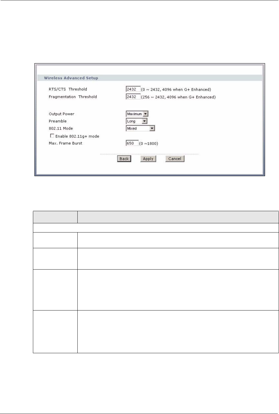
7.4.5 Wireless LAN Advanced Setup
To configure advanced wireless settings, click the Advanced Setup button in the General
screen. The screen appears as shown.
Figure 62 Advanced
The following table describes the labels in this screen.
Table 37 Wireless LAN: Advanced
LABEL DESCRIPTION
Wireless Advanced Setup
RTS/CTS
Threshold
Enter a value between 0 and 2432. If you select the Enable 802.11g+ mode
checkbox, this field is grayed out and the ZyXEL Device uses 4096 automatically.
Fragmentation
Threshold
It is the maximum data fragment size that can be sent. Enter a value between 256
and 2432. If you select the Enable 802.11g+ mode checkbox, this field is grayed
out and the ZyXEL Device uses 4096 automatically.
Output Power Set the output power of the ZyXEL Device in this field. This control changes the
strength of the ZyXEL Device's antenna gain or transmission power. Antenna gain is
the increase in coverage. Higher antenna gain improves the range of the signal for
better communications. If there is a high density of APs within an area, decrease the
output power of the ZyXEL Device to reduce interference with other APs.
The options are Maximum, Middle and Minimum.
Preamble Select Long preamble if you are unsure what preamble mode the wireless adapters
support, and to provide more reliable communications in busy wireless networks.
Select Short preamble if you are sure the wireless adapters support it, and to
provide more efficient communications.
Select Dynamic to have the ZyXEL Device automatically use short preamble when
wireless adapters support it, otherwise the ZyXEL Device uses long preamble.

P-660H/HW-D Series User’s Guide
Chapter 7 Wireless LAN 120
7.5 OTIST
In a wireless network, the wireless clients must have the same SSID and security settings as
the access point (AP) or wireless router (we will refer to both as “AP” here) in order to
associate with it. Traditionally this meant that you had to configure the settings on the AP and
then manually configure the exact same settings on each wireless client.
OTIST (One-Touch Intelligent Security Technology) allows you to transfer your AP’s SSID
and WPA-PSK security settings to wireless clients that support OTIST and are within
transmission range. You can also choose to have OTIST generate a WPA-PSK key for you if
you didn’t configure one manually.
Note: OTIST replaces the pre-configured wireless settings on the wireless clients.
7.5.1 Enabling OTIST
You must enable OTIST on both the AP and wireless client before you start transferring
settings.
Note: The AP and wireless client(s) MUST use the same Setup key.
802.11 Mode Select 802.11b Only to allow only IEEE 802.11b compliant WLAN devices to
associate with the ZyXEL Device.
Select 802.11g Only to allow only IEEE 802.11g compliant WLAN devices to
associate with the ZyXEL Device.
Select Mixed to allow either IEEE802.11b or IEEE802.11g compliant WLAN devices
to associate with the ZyXEL Device. The transmission rate of your ZyXEL Device
might be reduced.
Enable 802.11g+
mode
Select the Enable 802.11g+ mode checkbox to allow any ZyXEL WLAN devices
that support this feature to associate with the ZyXEL Device at higher transmission
speeds. This permits the ZyXEL Device to transmit at a higher speed than the
802.11g Only mode.
Max. Frame
Burst
Enable Maximum Frame Burst to help eliminate collisions in mixed-mode networks
(networks with both IEEE 802.11g and IEEE 802.11b traffic) and enhance the
performance of both pure IEEE 802.11g and mixed IEEE 802.11b/g networks.
Maximum Frame Burst sets the maximum time, in micro-seconds, that the ZZyXEL
Device transmits IEEE 802.11g wireless traffic only.
Type the maximum frame burst between 0 and 1800 (650, 1000 or 1800
recommended). Enter 0 to disable this feature.
Back Click Back to return to the previous screen.
Apply Click Apply to save your changes back to the ZyXEL Device.
Cancel Click Cancel to reload the previous configuration for this screen.
Table 37 Wireless LAN: Advanced
LABEL DESCRIPTION
P-660H/HW-D Series User’s Guide
121 Chapter 7 Wireless LAN
7.5.1.1 AP
You can enable OTIST using the RESET button or the web configurator.
7.5.1.1.1 Reset button
If you use the RESET button, the default (01234567) or previous saved (through the web
configurator) Setup key is used to encrypt the settings that you want to transfer.
Hold in the RESET button for one to five seconds.
Note: If you hold in the RESET button too long, the device will reset to the factory
defaults!
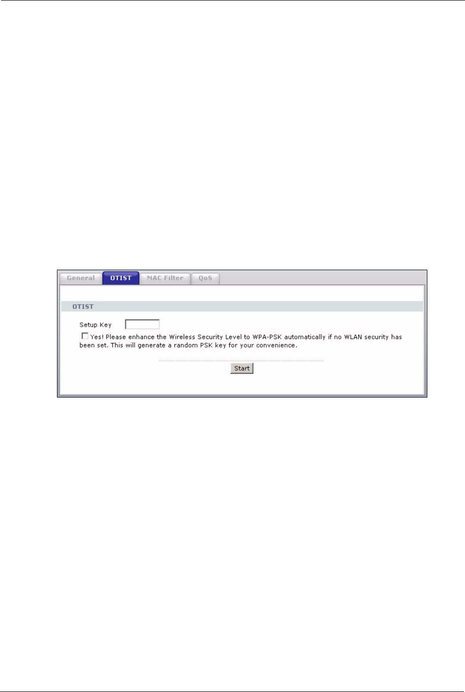
7.5.1.1.2 Web Configurator
Click the Network > Wireless LAN > OTIST. The following screen displays.
Figure 63 OTIST
P-660H/HW-D Series User’s Guide
Chapter 7 Wireless LAN 122
The following table describes the labels in this screen.
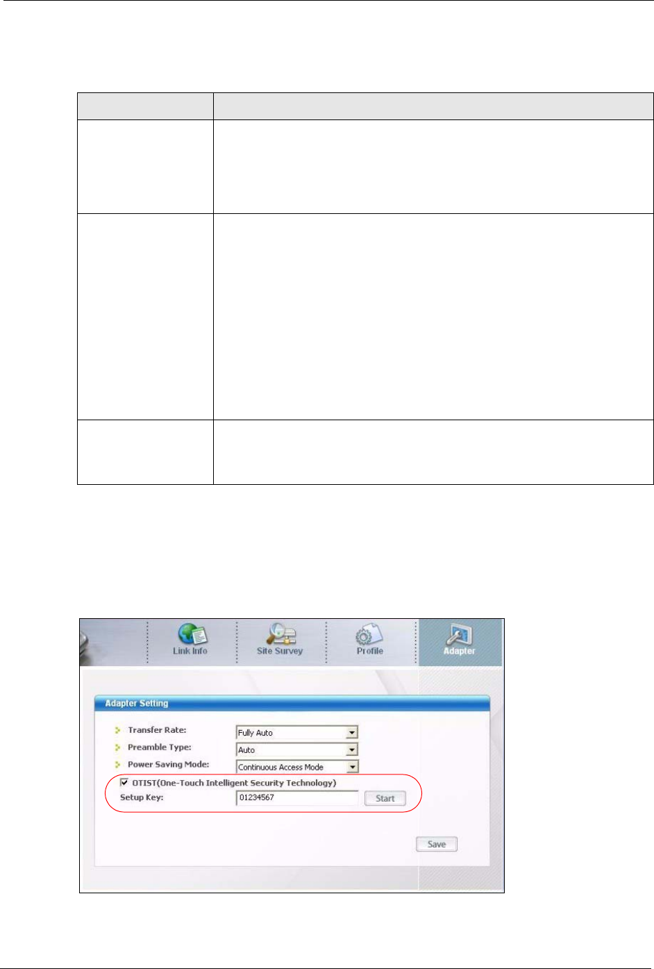
7.5.1.2 Wireless Client
Start the ZyXEL utility and click the Adapter tab. Select the OTIST check box, enter the
same Setup Key as your AP’s and click Save.
Figure 64 Example Wireless Client OTIST Screen
Table 38 OTIST
LABEL DESCRIPTION
Setup Key Type an OTIST Setup Key of exactly eight ASCII characters in length.
The default OTIST setup key is "01234567".
Note: If you change the OTIST setup key here, you must also
make the same change on the wireless client(s).
Yes! If you want OTIST to automatically generate a WPA-PSK, you must:
• Change your security to any security other than WPA-PSK in the Wireless
LAN > General screen.
• Select the Yes! checkbox in the OTIST screen and click Start.
• The wireless screen displays an auto generated WPA-PSK and is now in
WPA-PSK security mode.
The WPA-PSK security settings are assigned to the wireless client when you
start OTIST.
Note: If you already have a WPA-PSK configured in the
Wireless LAN > General screen, and you run OTIST with
Yes! selected, OTIST will use the existing WPA-PSK.
Start Click Start to encrypt the wireless security data using the setup key and have
the ZyXEL Device set the wireless client to use the same wireless settings as
the ZyXEL Device. You must also activate and start OTIST on the wireless
client all within three minutes.
P-660H/HW-D Series User’s Guide
123 Chapter 7 Wireless LAN
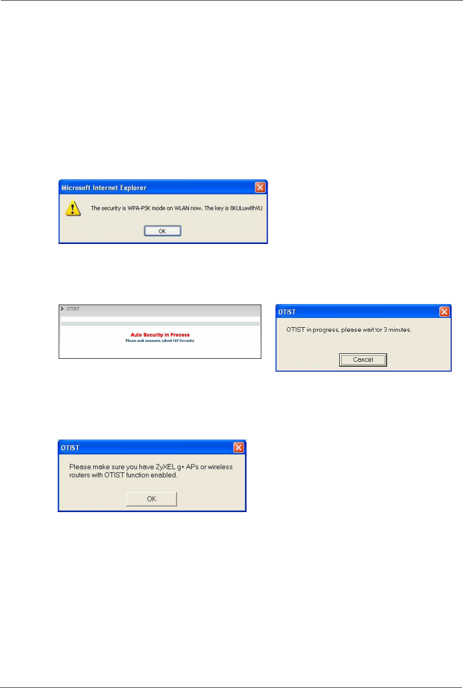
7.5.2 Starting OTIST
Note: You must click Start in the AP OTIST web configurator screen and in the
wireless client(s) Adapter screen all within three minutes (at the time of
writing). You can start OTIST in the wireless clients and AP in any order but
they must all be within range and have OTIST enabled.
1In the AP, a web configurator screen pops up showing you the security settings to
transfer. You can use the key in this screen to set up WPA-PSK encryption manually for
non-OTIST devices in the wireless network. After reviewing the settings, click OK.
Figure 65 Security Key
2This screen appears while OTIST settings are being transferred. It closes when the
transfer is complete.
• In the wireless client, you see this screen if it can't find an OTIST-enabled AP (with the
same Setup key). Click OK to go back to the ZyXEL utility main screen.
Figure 68 No AP with OTIST Found
• If there is more than one OTIST-enabled AP within range, you see a screen asking you to
select one AP to get settings from.
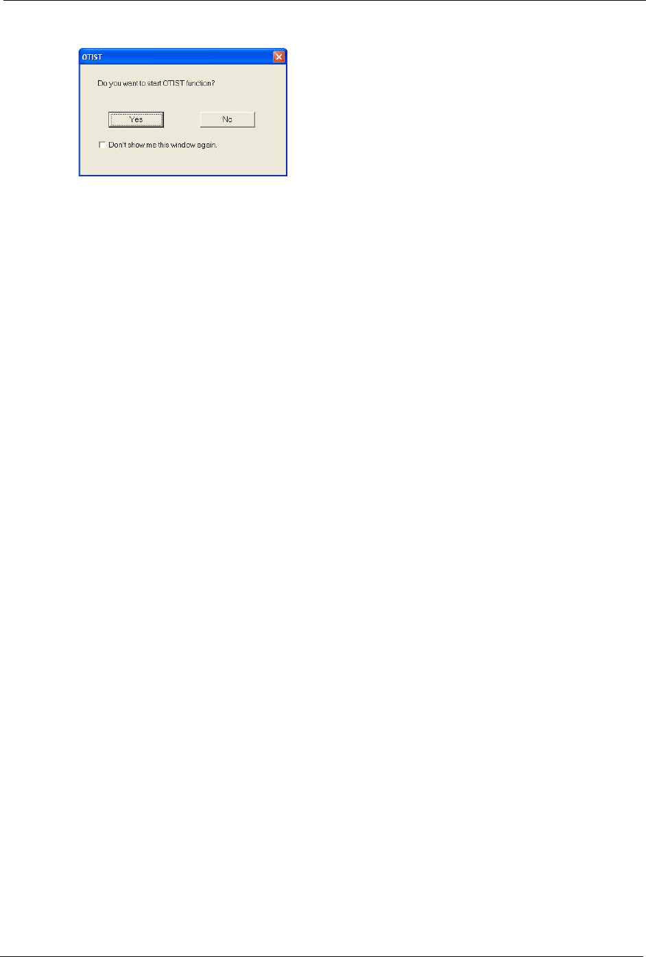
7.5.3 Notes on OTIST
1If you enabled OTIST in the wireless client, you see this screen each time you start the
utility. Click Yes for it to search for an OTIST-enabled AP.
Figure 66 OTIST in Progress (AP) Figure 67 OTIST in Progress (Client)
P-660H/HW-D Series User’s Guide
Chapter 7 Wireless LAN 124
Figure 69 Start OTIST?
2If an OTIST-enabled wireless client loses its wireless connection for more than ten
seconds, it will search for an OTIST-enabled AP for up to one minute. (If you manually
have the wireless client search for an OTIST-enabled AP, there is no timeout; click
Cancel in the OTIST progress screen to stop the search.)
3When the wireless client finds an OTIST-enabled AP, you must still click Start in the AP
OTIST web configurator screen or hold in the RESET button (for one to five seconds)
for the AP to transfer settings.
4If you change the SSID or the keys on the AP after using OTIST, you need to run OTIST
again or enter them manually in the wireless client(s).
5If you configure OTIST to generate a WPA-PSK key, this key changes each time you run
OTIST. Therefore, if a new wireless client joins your wireless network, you need to run
OTIST on the AP and ALL wireless clients again.
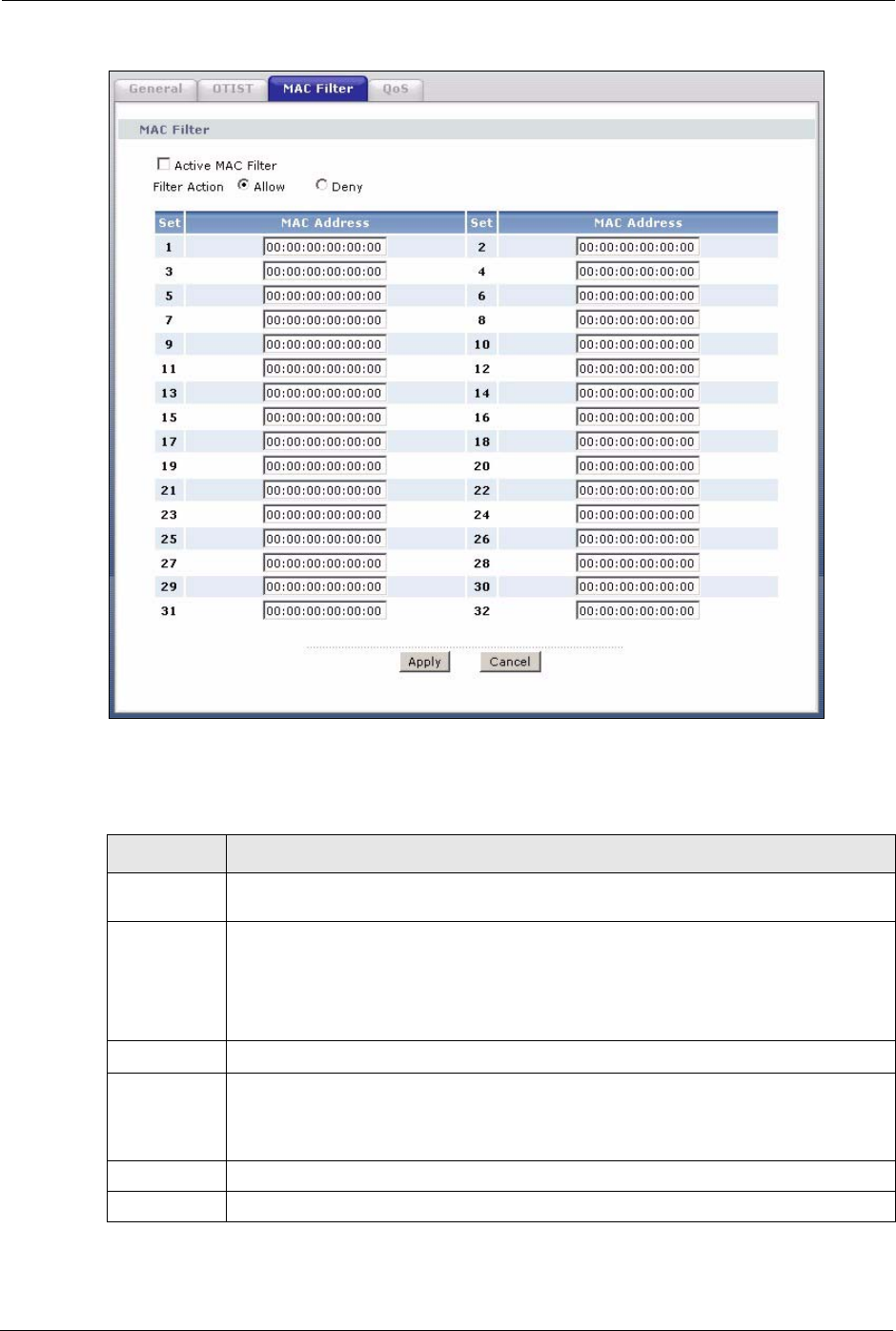
7.6 MAC Filter
The MAC filter screen allows you to configure the ZyXEL Device to give exclusive access to
up to 32 devices (Allow) or exclude up to 32 devices from accessing the ZyXEL Device
(Deny). Every Ethernet device has a unique MAC (Media Access Control) address. The MAC
address is assigned at the factory and consists of six pairs of hexadecimal characters, for
example, 00:A0:C5:00:00:02. You need to know the MAC address of the devices to configure
this screen.
To change your ZyXEL Device’s MAC filter settings, click Network > Wireless LAN >
MAC Filter. The screen appears as shown.
P-660H/HW-D Series User’s Guide
125 Chapter 7 Wireless LAN
Figure 70 MAC Address Filter
The following table describes the labels in this menu.
Table 39 MAC Address Filter
LABEL DESCRIPTION
Active MAC
Filter
Select the check box to enable MAC address filtering.
Filter Action Define the filter action for the list of MAC addresses in the MAC Address table.
Select Deny to block access to the ZyXEL Device, MAC addresses not listed will be
allowed to access the ZyXEL Device
Select Allow to permit access to the ZyXEL Device, MAC addresses not listed will be
denied access to the ZyXEL Device.
Set This is the index number of the MAC address.
MAC Address Enter the MAC addresses of the wireless client that are allowed or denied access to the
ZyXEL Device in these address fields. Enter the MAC addresses in a valid MAC
address format, that is, six hexadecimal character pairs, for example,
12:34:56:78:9a:bc.
Apply Click Apply to save your changes back to the ZyXEL Device.
Cancel Click Cancel to reload the previous configuration for this screen.
P-660H/HW-D Series User’s Guide
Chapter 7 Wireless LAN 126
7.7 WMM QoS
WMM (Wi-Fi MultiMedia) QoS (Quality of Service) allows you to prioritize wireless traffic
according to the delivery requirements of individual services.
WMM is a part of the IEEE 802.11e QoS enhancement to certified Wi-Fi wireless networks.
7.7.1 WMM QoS Example
When WMM QoS is not enabled, all traffic streams are given the same access throughput to
the wireless network. If the introduction of another traffic stream creates a data transmission
demand that exceeds the current network capacity, then the new traffic stream reduces the
throughput of the other traffic streams.
When WMM QoS is enabled, the streams are prioritized according to the needs of the
application. You can assign different priorities to different applications. This prevents
reductions in data transmission for applications that are sensitive.
7.7.2 WMM QoS Priorities
The following table describes the priorities that you can apply to traffic that the ZyXEL
Device sends to the wireless network.
Table 40 WMM QoS Priorities
PRIORITY LEVELS:
Highest Typically used for voice traffic or video that is especially sensitive to jitter
(variations in delay). Use the highest priority to reduce latency for improved voice
quality.
High Typically used for video traffic which has some tolerance for jitter but needs to be
prioritized over other data traffic.
Mid Typically used for traffic from applications or devices that lack QoS capabilities.
Use mid priority for traffic that is less sensitive to latency, but is affected by long
delays, such as Internet surfing.
Low This is typically used for non-critical “background” traffic such as bulk transfers
and print jobs that are allowed but that should not affect other applications and
users. Use low priority for applications that do not have strict latency and
throughput requirements.

P-660H/HW-D Series User’s Guide
127 Chapter 7 Wireless LAN
7.7.3 Services
The commonly used services and port numbers are shown in the following table. Please refer
to RFC 1700 for further information about port numbers. Next to the name of the service, two
fields appear in brackets. The first field indicates the IP protocol type (TCP, UDP, or ICMP).
The second field indicates the IP port number that defines the service. (Note that there may be
more than one IP protocol type. For example, look at the DNS service. (UDP/TCP:53) means
UDP port 53 and TCP port 53.
Table 41 Commonly Used Services
SERVICE DESCRIPTION
AIM/New-ICQ(TCP:5190) AOL’s Internet Messenger service, used as a listening port by ICQ.
AUTH(TCP:113) Authentication protocol used by some servers.
BGP(TCP:179) Border Gateway Protocol.
BOOTP_CLIENT(UDP:68) DHCP Client.
BOOTP_SERVER(UDP:67) DHCP Server.
CU-SEEME(TCP/UDP:7648,
24032)
A popular videoconferencing solution from White Pines Software.
DNS(UDP/TCP:53) Domain Name Server, a service that matches web names (e.g.
www.zyxel.com) to IP numbers.
FINGER(TCP:79) Finger is a UNIX or Internet related command that can be used to
find out if a user is logged on.
FTP(TCP:20.21) File Transfer Program, a program to enable fast transfer of files,
including large files that may not be possible by e-mail.
H.323(TCP:1720) NetMeeting uses this protocol.
HTTP(TCP:80) Hyper Text Transfer Protocol - a client/server protocol for the world
wide web.
HTTPS(TCP:443) HTTPS is a secured http session often used in e-commerce.
ICQ(UDP:4000) This is a popular Internet chat program.
IKE(UDP:500) The Internet Key Exchange algorithm is used for key distribution and
management.
IPSEC_TUNNEL(AH:0) The IPSEC AH (Authentication Header) tunneling protocol uses this
service.
IPSEC_TUNNEL(ESP:0) The IPSEC ESP (Encapsulation Security Protocol) tunneling protocol
uses this service.
IRC(TCP/UDP:6667) This is another popular Internet chat program.
MSN Messenger(TCP:1863) Microsoft Networks’ messenger service uses this protocol.
MULTICAST(IGMP:0) Internet Group Multicast Protocol is used when sending packets to a
specific group of hosts.
NEW-ICQ(TCP:5190) An Internet chat program.
NEWS(TCP:144) A protocol for news groups.
NFS(UDP:2049) Network File System - NFS is a client/server distributed file service
that provides transparent file sharing for network environments.
NNTP(TCP:119) Network News Transport Protocol is the delivery mechanism for the
USENET newsgroup service.

P-660H/HW-D Series User’s Guide
Chapter 7 Wireless LAN 128
7.8 QoS Screen
The QoS screen by default allows you to automatically give a service a priority level
according to the ToS value in the IP header of the packets it sends.
PING(ICMP:0) Packet INternet Groper is a protocol that sends out ICMP echo
requests to test whether or not a remote host is reachable.
POP3(TCP:110) Post Office Protocol version 3 lets a client computer get e-mail from a
POP3 server through a temporary connection (TCP/IP or other).
PPTP(TCP:1723) Point-to-Point Tunneling Protocol enables secure transfer of data
over public networks. This is the control channel.
PPTP_TUNNEL(GRE:0) Point-to-Point Tunneling Protocol enables secure transfer of data
over public networks. This is the data channel.
RCMD(TCP:512) Remote Command Service.
REAL_AUDIO(TCP:7070) A streaming audio service that enables real time sound over the web.
REXEC(TCP:514) Remote Execution Daemon.
RLOGIN(TCP:513) Remote Login.
RTELNET(TCP:107) Remote Telnet.
RTSP(TCP/UDP:554) The Real Time Streaming (media control) Protocol (RTSP) is a
remote control for multimedia on the Internet.
SFTP(TCP:115) Simple File Transfer Protocol.
SMTP(TCP:25) Simple Mail Transfer Protocol is the message-exchange standard for
the Internet. SMTP enables you to move messages from one e-mail
server to another.
SNMP(TCP/UDP:161) Simple Network Management Program.
SNMP-TRAPS(TCP/UDP:162) Traps for use with the SNMP (RFC:1215).
SQL-NET(TCP:1521) Structured Query Language is an interface to access data on many
different types of database systems, including mainframes, midrange
systems, UNIX systems and network servers.
SSH(TCP/UDP:22) Secure Shell Remote Login Program.
STRM WORKS(UDP:1558) Stream Works Protocol.
SYSLOG(UDP:514) Syslog allows you to send system logs to a UNIX server.
TACACS(UDP:49) Login Host Protocol used for (Terminal Access Controller Access
Control System).
TELNET(TCP:23) Telnet is the login and terminal emulation protocol common on the
Internet and in UNIX environments. It operates over TCP/IP
networks. Its primary function is to allow users to log into remote host
systems.
TFTP(UDP:69) Trivial File Transfer Protocol is an Internet file transfer protocol
similar to FTP, but uses the UDP (User Datagram Protocol) rather
than TCP (Transmission Control Protocol).
VDOLIVE(TCP:7000) Another videoconferencing solution.
Table 41 Commonly Used Services
SERVICE DESCRIPTION
P-660H/HW-D Series User’s Guide
129 Chapter 7 Wireless LAN
7.8.1 ToS (Type of Service) and WMM QoS
ToS defines the DS (Differentiated Service) field in the IP packet header. The ToS value of
outgoing packets is between 0 and 255. 0 is the lowest priority.
WMM QoS checks the ToS in the header of transmitted data packets. It gives the application a
priority according to this number. If the ToS is not specified, then transmitted data is treated as
normal or best-effort traffic.
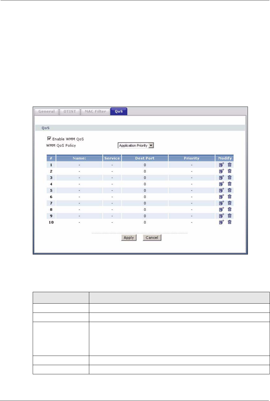
Click Network > Wireless LAN > QoS. The following screen displays.
Figure 71 Wireless LAN: QoS
The following table describes the fields in this screen.
Table 42 Wireless LAN: QoS
LABEL DESCRIPTION
QoS
Enable WMM QoS Select the check box to enable WMM QoS on the ZyXEL Device.
WMM QoS Policy Select Default to have the ZyXEL Device automatically give a service a
priority level according to the ToS value in the IP header of packets it sends.
Select Application Priority from the drop-down list box to display a table of
application names, services, ports and priorities to which you want to apply
WMM QoS.
# This is the number of an individual application entry.
Name This field displays a description given to an application entry.
P-660H/HW-D Series User’s Guide
Chapter 7 Wireless LAN 130
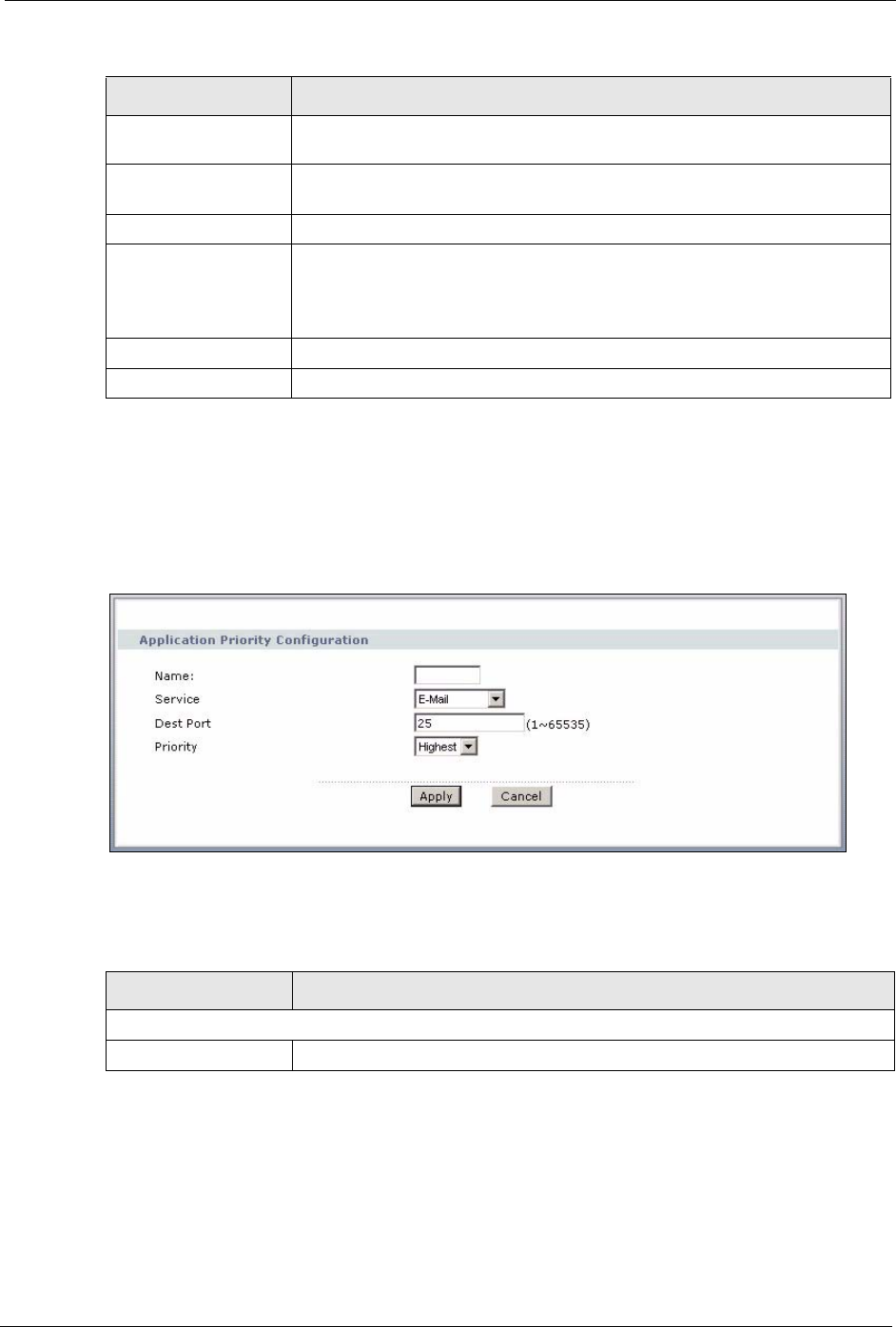
7.8.2 Application Priority Configuration
To edit a WMM QoS application entry, click the edit icon under Modify. The following
screen displays.
Figure 72 Application Priority Configuration
The following table describes the fields in this screen.
Service This field displays either FTP, WWW, E-mail or a User Defined service to
which you want to apply WMM QoS.
Dest Port This field displays the destination port number to which the application sends
traffic.
Priority This field displays the WMM QoS priority for traffic bandwidth.
Modify Click the Edit icon to open the Application Priority Configuration screen.
Modify an existing application entry or create a application entry in the
Application Priority Configuration screen.
Click the Remove icon to delete an application entry.
Apply Click Apply to save your changes back to the ZyXEL Device.
Cancel Click Cancel to reload the previous configuration for this screen.
Table 42 Wireless LAN: QoS
LABEL DESCRIPTION
Table 43 Application Priority Configuration
LABEL DESCRIPTION
Application Priority Configuration
Name Type a description of the application priority.

P-660H/HW-D Series User’s Guide
131 Chapter 7 Wireless LAN
Service The following is a description of the applications you can prioritize with WMM
QoS. Select a service from the drop-down list box.
•FTP
File Transfer Program enables fast transfer of files, including large files that
may not be possible by e-mail. FTP uses port number 21.
• E-Mail
Electronic mail consists of messages sent through a computer network to
specific groups or individuals. Here are some default ports for e-mail:
POP3 - port 110
IMAP - port 143
SMTP - port 25
HTTP - port 80
•WWW
The World Wide Web is an Internet system to distribute graphical, hyper-linked
information, based on Hyper Text Transfer Protocol (HTTP) - a client/server
protocol for the World Wide Web. The Web is not synonymous with the
Internet; rather, it is just one service on the Internet. Other services on the
Internet include Internet Relay Chat and Newsgroups. The Web is accessed
through use of a browser.
•User-Defined
User-defined services are user specific services configured using known ports
and applications.
Dest Port This displays the port the selected service uses. Type a port number in the
field provided if you want to use a different port to the default port. See table
Table 41 on page 127 for information on port numbers.
Priority Select a priority from the drop-down list box.
Apply Click Apply to save your changes back to the ZyXEL Device.
Cancel Click Cancel to return to the previous screen without saving your changes.
Table 43 Application Priority Configuration
LABEL DESCRIPTION

P-660H/HW-D Series User’s Guide
Chapter 8 Network Address Translation (NAT) Screens 132
CHAPTER 8
Network Address Translation
(NAT) Screens
This chapter discusses how to configure NAT on the ZyXEL Device.
8.1 NAT Overview
NAT (Network Address Translation - NAT, RFC 1631) is the translation of the IP address of a
host in a packet, for example, the source address of an outgoing packet, used within one
network to a different IP address known within another network.
8.1.1 NAT Definitions
Inside/outside denotes where a host is located relative to the ZyXEL Device, for example, the
computers of your subscribers are the inside hosts, while the web servers on the Internet are
the outside hosts.
Global/local denotes the IP address of a host in a packet as the packet traverses a router, for
example, the local address refers to the IP address of a host when the packet is in the local
network, while the global address refers to the IP address of the host when the same packet is
traveling in the WAN side.
Note that inside/outside refers to the location of a host, while global/local refers to the IP
address of a host used in a packet. Thus, an inside local address (ILA) is the IP address of an
inside host in a packet when the packet is still in the local network, while an inside global
address (IGA) is the IP address of the same inside host when the packet is on the WAN side.
The following table summarizes this information.
NAT never changes the IP address (either local or global) of an outside host.
Table 44 NAT Definitions
ITEM DESCRIPTION
Inside This refers to the host on the LAN.
Outside This refers to the host on the WAN.
Local This refers to the packet address (source or destination) as the packet travels on the
LAN.
Global This refers to the packet address (source or destination) as the packet travels on the
WAN.
P-660H/HW-D Series User’s Guide
133 Chapter 8 Network Address Translation (NAT) Screens
8.1.2 What NAT Does
In the simplest form, NAT changes the source IP address in a packet received from a
subscriber (the inside local address) to another (the inside global address) before forwarding
the packet to the WAN side. When the response comes back, NAT translates the destination
address (the inside global address) back to the inside local address before forwarding it to the
original inside host. Note that the IP address (either local or global) of an outside host is never
changed.
The global IP addresses for the inside hosts can be either static or dynamically assigned by the
ISP. In addition, you can designate servers, for example, a web server and a telnet server, on
your local network and make them accessible to the outside world. If you do not define any
servers (for Many-to-One and Many-to-Many Overload mapping – see Table 45 on page 135),
NAT offers the additional benefit of firewall protection. With no servers defined, your ZyXEL
Device filters out all incoming inquiries, thus preventing intruders from probing your network.
For more information on IP address translation, refer to RFC 1631, The IP Network Address
Translator (NAT).
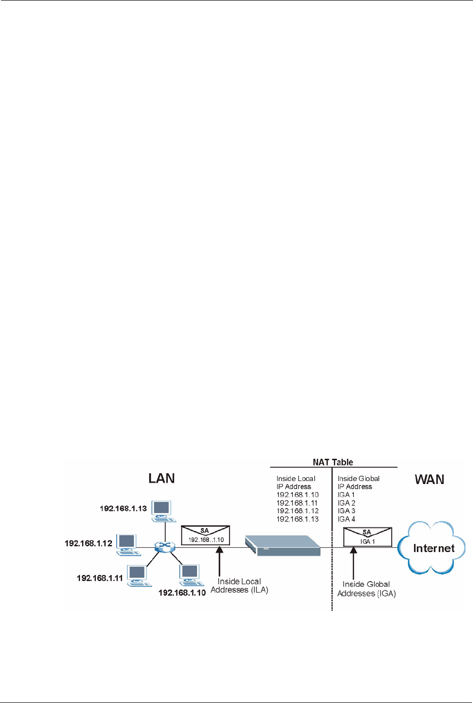
8.1.3 How NAT Works
Each packet has two addresses – a source address and a destination address. For outgoing
packets, the ILA (Inside Local Address) is the source address on the LAN, and the IGA (Inside
Global Address) is the source address on the WAN. For incoming packets, the ILA is the
destination address on the LAN, and the IGA is the destination address on the WAN. NAT
maps private (local) IP addresses to globally unique ones required for communication with
hosts on other networks. It replaces the original IP source address (and TCP or UDP source
port numbers for Many-to-One and Many-to-Many Overload NAT mapping) in each packet
and then forwards it to the Internet. The ZyXEL Device keeps track of the original addresses
and port numbers so incoming reply packets can have their original values restored. The
following figure illustrates this.
Figure 73 How NAT Works
P-660H/HW-D Series User’s Guide
Chapter 8 Network Address Translation (NAT) Screens 134
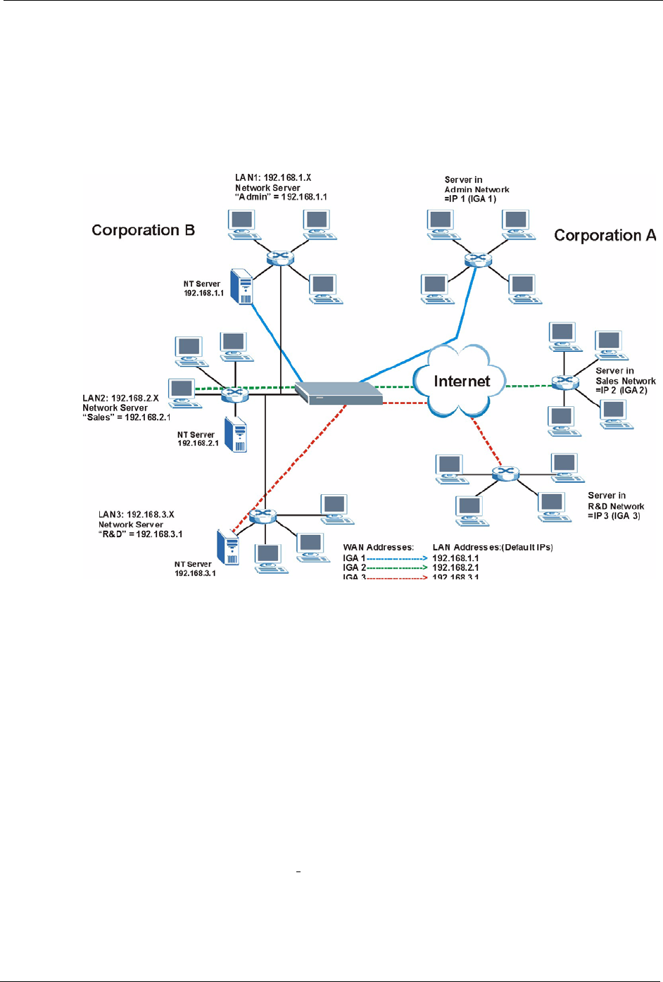
8.1.4 NAT Application
The following figure illustrates a possible NAT application, where three inside LANs (logical
LANs using IP Alias) behind the ZyXEL Device can communicate with three distinct WAN
networks. More examples follow at the end of this chapter.
Figure 74 NAT Application With IP Alias
8.1.5 NAT Mapping Types
NAT supports five types of IP/port mapping. They are:
•One to One: In One-to-One mode, the ZyXEL Device maps one local IP address to one
global IP address.
•Many to One: In Many-to-One mode, the ZyXEL Device maps multiple local IP
addresses to one global IP address. This is equivalent to SUA (for instance, PAT, port
address translation), ZyXEL’s Single User Account feature that previous ZyXEL routers
supported (the SUA Only option in today’s routers).
•Many to Many Overload: In Many-to-Many Overload mode, the ZyXEL Device maps
the multiple local IP addresses to shared global IP addresses.
•Many-to-Many No Overload: In Many-to-Many No Overload mode, the ZyXEL Device
maps each local IP address to a unique global IP address.
•Server: This type allows you to specify inside servers of different services behind the
NAT to be accessible to the outside world.

P-660H/HW-D Series User’s Guide
135 Chapter 8 Network Address Translation (NAT) Screens
Port numbers do NOT change for One-to-One and Many-to-Many No Overload NAT
mapping types.
The following table summarizes these types.
8.2 SUA (Single User Account) Versus NAT
SUA (Single User Account) is a ZyNOS implementation of a subset of NAT that supports two
types of mapping, Many-to-One and Server. The ZyXEL Device also supports Full
Feature NAT to map multiple global IP addresses to multiple private LAN IP addresses of
clients or servers using mapping types as outlined in Table 45 on page 135.
• Choose SUA Only if you have just one public WAN IP address for your ZyXEL Device.
• Choose Full Feature if you have multiple public WAN IP addresses for your ZyXEL
Device.
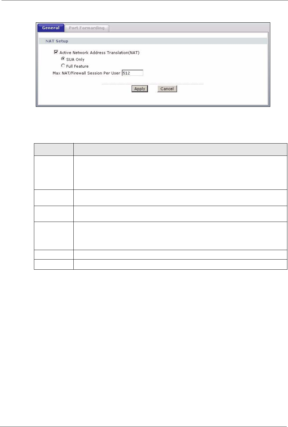
8.3 NAT General Setup
You must create a firewall rule in addition to setting up SUA/NAT, to allow traffic from the
WAN to be forwarded through the ZyXEL Device. Click Network > NAT to open the
following screen. Not all fields are available on all models.
Table 45 NAT Mapping Types
TYPE IP MAPPING
One-to-One ILA1ÅÆ IGA1
Many-to-One (SUA/PAT) ILA1ÅÆ IGA1
ILA2ÅÆ IGA1
…
Many-to-Many Overload ILA1ÅÆ IGA1
ILA2ÅÆ IGA2
ILA3ÅÆ IGA1
ILA4ÅÆ IGA2
…
Many-to-Many No Overload ILA1ÅÆ IGA1
ILA2ÅÆ IGA2
ILA3ÅÆ IGA3
…
Server Server 1 IPÅÆ IGA1
Server 2 IPÅÆ IGA1
Server 3 IPÅÆ IGA1
P-660H/HW-D Series User’s Guide
Chapter 8 Network Address Translation (NAT) Screens 136
Figure 75 NAT General (P-660H-D)
The following table describes the labels in this screen.
8.4 Port Forwarding
A port forwarding set is a list of inside (behind NAT on the LAN) servers, for example, web or
FTP, that you can make visible to the outside world even though NAT makes your whole
inside network appear as a single computer to the outside world.
You may enter a single port number or a range of port numbers to be forwarded, and the local
IP address of the desired server. The port number identifies a service; for example, web
service is on port 80 and FTP on port 21. In some cases, such as for unknown services or
where one server can support more than one service (for example both FTP and web service),
it might be better to specify a range of port numbers. You can allocate a server IP address that
corresponds to a port or a range of ports.
Table 46 NAT General
LABEL DESCRIPTION
Active
Network
Address
Translation
(NAT)
Select this check box to enable NAT.
SUA Only Select this radio button if you have just one public WAN IP address for your ZyXEL
Device.
Full Feature Select this radio button if you have multiple public WAN IP addresses for your ZyXEL
Device.
Max NAT/
Firewall
Session Per
User
Enter the highest number of concurrent NAT and/or firewall sessions that the ZyXEL
Device will permit a user to have.
Apply Click Apply to save your changes back to the ZyXEL Device.
Cancel Click Cancel to reload the previous configuration for this screen.

P-660H/HW-D Series User’s Guide
137 Chapter 8 Network Address Translation (NAT) Screens
Many residential broadband ISP accounts do not allow you to run any server processes (such
as a Web or FTP server) from your location. Your ISP may periodically check for servers and
may suspend your account if it discovers any active services at your location. If you are
unsure, refer to your ISP.
8.4.1 Default Server IP Address
In addition to the servers for specified services, NAT supports a default server IP address. A
default server receives packets from ports that are not specified in this screen.
Note: If you do not assign a Default Server IP address, the ZyXEL Device discards
all packets received for ports that are not specified here or in the remote
management setup.
8.4.2 Port Forwarding: Services and Port Numbers
Use the Port Forwarding screen to forward incoming service requests to the server(s) on your
local network.
The most often used port numbers are shown in the following table. Please refer to RFC 1700
for further information about port numbers.
8.4.3 Configuring Servers Behind Port Forwarding (Example)
Let's say you want to assign ports 21-25 to one FTP, Telnet and SMTP server (A in the
example), port 80 to another (B in the example) and assign a default server IP address of
192.168.1.35 to a third (C in the example). You assign the LAN IP addresses and the ISP
assigns the WAN IP address. The NAT network appears as a single host on the Internet.
Table 47 Services and Port Numbers
SERVICES PORT NUMBER
ECHO 7
FTP (File Transfer Protocol) 21
SMTP (Simple Mail Transfer Protocol) 25
DNS (Domain Name System) 53
Finger 79
HTTP (Hyper Text Transfer protocol or WWW, Web) 80
POP3 (Post Office Protocol) 110
NNTP (Network News Transport Protocol) 119
SNMP (Simple Network Management Protocol) 161
SNMP trap 162
PPTP (Point-to-Point Tunneling Protocol) 1723

P-660H/HW-D Series User’s Guide
Chapter 8 Network Address Translation (NAT) Screens 138
Figure 76 Multiple Servers Behind NAT Example
8.5 Configuring Port Forwarding
Note: The Port Forwarding screen is available only when you select SUA Only in
the NAT > General screen.
If you do not assign a Default Server IP address, the ZyXEL Device discards
all packets received for ports that are not specified here or in the remote
management setup.
Click Network > NAT > Port Forwarding to open the following screen.
See Table 47 on page 137 for port numbers commonly used for particular services.
Figure 77 NAT Port Forwarding
P-660H/HW-D Series User’s Guide
139 Chapter 8 Network Address Translation (NAT) Screens
The following table describes the fields in this screen.
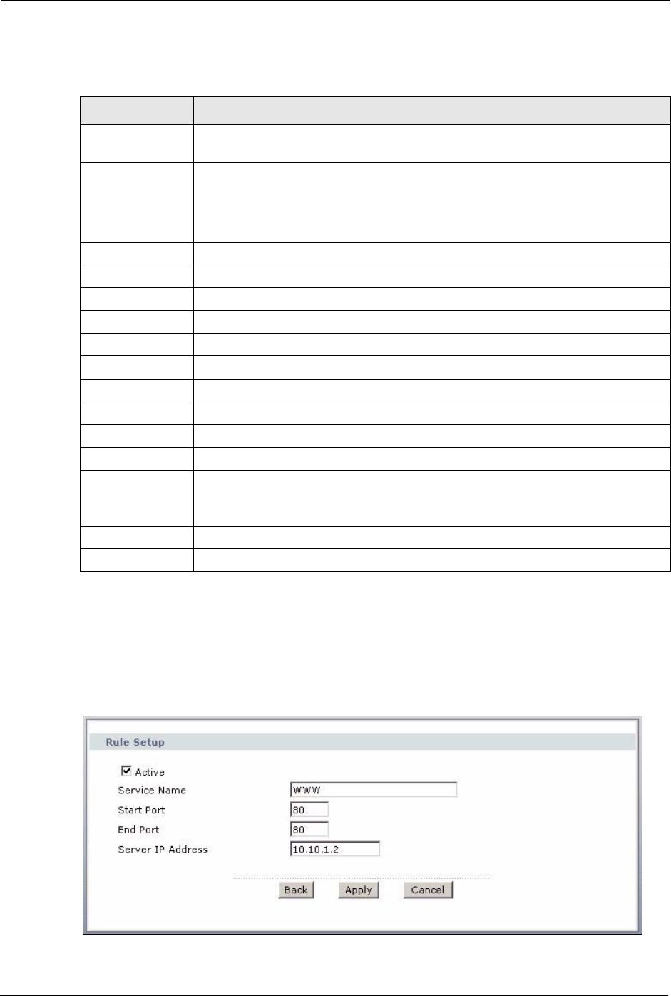
8.5.1 Port Forwarding Rule Edit
To edit a port forwarding rule, click the rule’s edit icon in the Port Forwarding screen to
display the screen shown next.
Figure 78 Port Forwarding Rule Setup
Table 48 NAT Port Forwarding
LABEL DESCRIPTION
Default Server
Setup
Default Server In addition to the servers for specified services, NAT supports a default server. A
default server receives packets from ports that are not specified in this screen. If
you do not assign a Default Server IP address, the ZyXEL Device discards all
packets received for ports that are not specified here or in the remote management
setup.
Port Forwarding
Service Name Select a service from the drop-down list box.
Server IP Address Enter the IP address of the server for the specified service.
Add Click this button to add a rule to the table below.
#This is the rule index number (read-only).
Active Click this check box to enable the rule.
Service Name This is a service’s name.
Start Port This is the first port number that identifies a service.
End Port This is the last port number that identifies a service.
Server IP Address This is the server’s IP address.
Modify Click the edit icon to go to the screen where you can edit the port forwarding rule.
Click the delete icon to delete an existing port forwarding rule. Note that
subsequent rules move up by one when you take this action.
Apply Click Apply to save your changes back to the ZyXEL Device.
Cancel Click Cancel to return to the previous configuration.

P-660H/HW-D Series User’s Guide
Chapter 8 Network Address Translation (NAT) Screens 140
The following table describes the fields in this screen.
8.6 Address Mapping
Note: The Address Mapping screen is available only when you select Full Feature
in the NAT > General screen.
Ordering your rules is important because the ZyXEL Device applies the rules in the order that
you specify. When a rule matches the current packet, the ZyXEL Device takes the
corresponding action and the remaining rules are ignored. If there are any empty rules before
your new configured rule, your configured rule will be pushed up by that number of empty
rules. For example, if you have already configured rules 1 to 6 in your current set and now you
configure rule number 9. In the set summary screen, the new rule will be rule 7, not 9. Now if
you delete rule 4, rules 5 to 7 will be pushed up by 1 rule, so old rules 5, 6 and 7 become new
rules 4, 5 and 6.
To change your ZyXEL Device’s address mapping settings, click Network > NAT > Address
Mapping to open the following screen.
Table 49 Port Forwarding Rule Setup
LABEL DESCRIPTION
Active Click this check box to enable the rule.
Service Name Enter a name to identify this port-forwarding rule.
Start Port Enter a port number in this field.
To forward only one port, enter the port number again in the End Port field.
To forward a series of ports, enter the start port number here and the end port
number in the End Port field.
End Port Enter a port number in this field.
To forward only one port, enter the port number again in the Start Port field above
and then enter it again in this field.
To forward a series of ports, enter the last port number in a series that begins with
the port number in the Start Port field above.
Server IP
Address
Enter the inside IP address of the server here.
Back Click Back to return to the previous screen.
Apply Click Apply to save your changes back to the ZyXEL Device.
Cancel Click Cancel to begin configuring this screen afresh.
P-660H/HW-D Series User’s Guide
141 Chapter 8 Network Address Translation (NAT) Screens
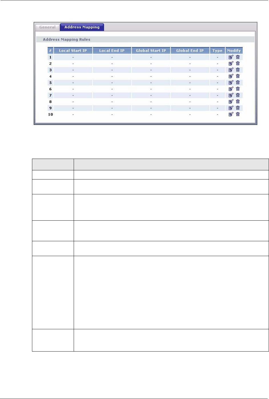
Figure 79 Address Mapping Rules
The following table describes the fields in this screen.
Table 50 Address Mapping Rules
LABEL DESCRIPTION
#This is the rule index number.
Local Start IP This is the starting Inside Local IP Address (ILA). Local IP addresses are N/A for
Server port mapping.
Local End IP This is the end Inside Local IP Address (ILA). If the rule is for all local IP addresses,
then this field displays 0.0.0.0 as the Local Start IP address and 255.255.255.255
as the Local End IP address. This field is N/A for One-to-one and Server mapping
types.
Global Start IP This is the starting Inside Global IP Address (IGA). Enter 0.0.0.0 here if you have a
dynamic IP address from your ISP. You can only do this for Many-to-One and
Server mapping types.
Global End IP This is the ending Inside Global IP Address (IGA). This field is N/A for One-to-one,
Many-to-One and Server mapping types.
Type 1-1: One-to-one mode maps one local IP address to one global IP address. Note that
port numbers do not change for the One-to-one NAT mapping type.
M-1: Many-to-One mode maps multiple local IP addresses to one global IP address.
This is equivalent to SUA (i.e., PAT, port address translation), ZyXEL's Single User
Account feature that previous ZyXEL routers supported only.
M-M Ov (Overload): Many-to-Many Overload mode maps multiple local IP addresses
to shared global IP addresses.
MM No (No Overload): Many-to-Many No Overload mode maps each local IP
address to unique global IP addresses.
Server: This type allows you to specify inside servers of different services behind the
NAT to be accessible to the outside world.
Modify Click the edit icon to go to the screen where you can edit the address mapping rule.
Click the delete icon to delete an existing address mapping rule. Note that
subsequent address mapping rules move up by one when you take this action.

P-660H/HW-D Series User’s Guide
Chapter 8 Network Address Translation (NAT) Screens 142
8.6.1 Address Mapping Rule Edit
To edit an address mapping rule, click the rule’s edit icon in the Address Mapping screen to
display the screen shown next.
Figure 80 Edit Address Mapping Rule
The following table describes the fields in this screen.
Table 51 Edit Address Mapping Rule
LABEL DESCRIPTION
Type Choose the port mapping type from one of the following.
•One-to-One: One-to-One mode maps one local IP address to one global IP
address. Note that port numbers do not change for One-to-one NAT mapping
type.
•Many-to-One: Many-to-One mode maps multiple local IP addresses to one
global IP address. This is equivalent to SUA (i.e., PAT, port address translation),
ZyXEL's Single User Account feature that previous ZyXEL routers supported
only.
•Many-to-Many Overload: Many-to-Many Overload mode maps multiple local IP
addresses to shared global IP addresses.
•Many-to-Many No Overload: Many-to-Many No Overload mode maps each
local IP address to unique global IP addresses.
•Server: This type allows you to specify inside servers of different services behind
the NAT to be accessible to the outside world.
Local Start IP This is the starting local IP address (ILA). Local IP addresses are N/A for Server port
mapping.
Local End IP This is the end local IP address (ILA). If your rule is for all local IP addresses, then
enter 0.0.0.0 as the Local Start IP address and 255.255.255.255 as the Local End
IP address.
This field is N/A for One-to-One and Server mapping types.
Global Start IP This is the starting global IP address (IGA). Enter 0.0.0.0 here if you have a dynamic
IP address from your ISP.
Global End IP This is the ending global IP address (IGA). This field is N/A for One-to-One, Many-
to-One and Server mapping types.
Server Mapping
Set
Only available when Type is set to Server.
Select a number from the drop-down menu to choose a server mapping set.

P-660H/HW-D Series User’s Guide
143 Chapter 8 Network Address Translation (NAT) Screens
Edit Details Click this link to go to the Port Forwarding screen to edit a server mapping set that
you have selected in the Server Mapping Set field.
Back Click Back to return to the previous screen.
Apply Click Apply to save your changes back to the ZyXEL Device.
Cancel Click Cancel to begin configuring this screen afresh.
Table 51 Edit Address Mapping Rule (continued)
LABEL DESCRIPTION

P-660H/HW-D Series User’s Guide
Chapter 9 Firewalls 144
CHAPTER 9
Firewalls
This chapter gives some background information on firewalls and introduces the ZyXEL
Device firewall.
9.1 Firewall Overview
Originally, the term firewall referred to a construction technique designed to prevent the
spread of fire from one room to another. The networking term “firewall” is a system or group
of systems that enforces an access-control policy between two networks. It may also be
defined as a mechanism used to protect a trusted network from an untrusted network. Of
course, firewalls cannot solve every security problem. A firewall is one of the mechanisms
used to establish a network security perimeter in support of a network security policy. It
should never be the only mechanism or method employed. For a firewall to guard effectively,
you must design and deploy it appropriately. This requires integrating the firewall into a broad
information-security policy. In addition, specific policies must be implemented within the
firewall itself.
Refer to Section 10.5 on page 159 to configure default firewall settings.
Refer to Section 10.6 on page 160 to view firewall rules.
Refer to Section 10.6.1 on page 162 to configure firewall rules.
Refer to Section 10.6.2 on page 165 to configure a custom service.
Refer to Section 10.10.3 on page 175 to configure firewall thresholds.
9.2 Types of Firewalls
There are three main types of firewalls:
• Packet Filtering Firewalls
• Application-level Firewalls
• Stateful Inspection Firewalls
9.2.1 Packet Filtering Firewalls
Packet filtering firewalls restrict access based on the source/destination computer network
address of a packet and the type of application.

P-660H/HW-D Series User’s Guide
145 Chapter 9 Firewalls
9.2.2 Application-level Firewalls
Application-level firewalls restrict access by serving as proxies for external servers. Since they
use programs written for specific Internet services, such as HTTP, FTP and telnet, they can
evaluate network packets for valid application-specific data. Application-level gateways have
a number of general advantages over the default mode of permitting application traffic directly
to internal hosts:
Information hiding prevents the names of internal systems from being made known via DNS
to outside systems, since the application gateway is the only host whose name must be made
known to outside systems.
Robust authentication and logging pre-authenticates application traffic before it reaches
internal hosts and causes it to be logged more effectively than if it were logged with standard
host logging. Filtering rules at the packet filtering router can be less complex than they would
be if the router needed to filter application traffic and direct it to a number of specific systems.
The router need only allow application traffic destined for the application gateway and reject
the rest.
9.2.3 Stateful Inspection Firewalls
Stateful inspection firewalls restrict access by screening data packets against defined access
rules. They make access control decisions based on IP address and protocol. They also
"inspect" the session data to assure the integrity of the connection and to adapt to dynamic
protocols. These firewalls generally provide the best speed and transparency, however, they
may lack the granular application level access control or caching that some proxies support.
See Section 9.5 on page 150 for more information on stateful inspection.
Firewalls, of one type or another, have become an integral part of standard security solutions
for enterprises.
9.3 Introduction to ZyXEL’s Firewall
The ZyXEL Device firewall is a stateful inspection firewall and is designed to protect against
Denial of Service attacks when activated. The ZyXEL Device’s purpose is to allow a private
Local Area Network (LAN) to be securely connected to the Internet. The ZyXEL Device can
be used to prevent theft, destruction and modification of data, as well as log events, which may
be important to the security of your network. The ZyXEL Device also has packet filtering
capabilities.
The ZyXEL Device is installed between the LAN and the Internet. This allows it to act as a
secure gateway for all data passing between the Internet and the LAN.
The ZyXEL Device has one DSL/ISDN port and one Ethernet LAN port, which physically
separate the network into two areas.
• The DSL/ISDN port connects to the Internet.
P-660H/HW-D Series User’s Guide
Chapter 9 Firewalls 146
• The LAN (Local Area Network) port attaches to a network of computers, which needs
security from the outside world. These computers will have access to Internet services
such as e-mail, FTP, and the World Wide Web. However, “inbound access” will not be
allowed unless you configure remote management or create a firewall rule to allow a
remote host to use a specific service.
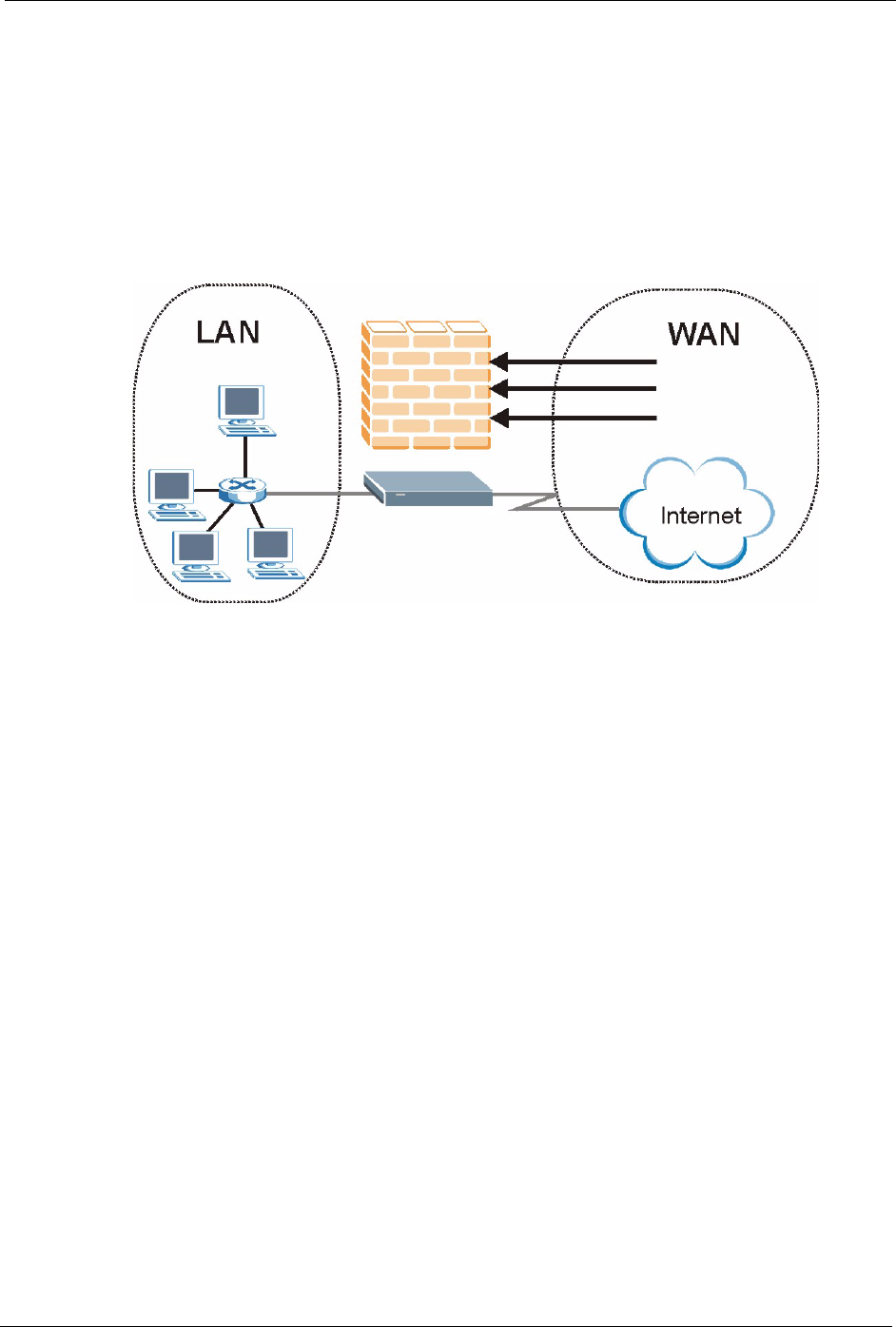
9.3.1 Denial of Service Attacks
Figure 81 Firewall Application
9.4 Denial of Service
Denials of Service (DoS) attacks are aimed at devices and networks with a connection to the
Internet. Their goal is not to steal information, but to disable a device or network so users no
longer have access to network resources. The ZyXEL Device is pre-configured to
automatically detect and thwart all known DoS attacks.
9.4.1 Basics
Computers share information over the Internet using a common language called TCP/IP. TCP/
IP, in turn, is a set of application protocols that perform specific functions. An “extension
number”, called the "TCP port" or "UDP port" identifies these protocols, such as HTTP
(Web), FTP (File Transfer Protocol), POP3 (E-mail), etc. For example, Web traffic by default
uses TCP port 80.
When computers communicate on the Internet, they are using the client/server model, where
the server "listens" on a specific TCP/UDP port for information requests from remote client
computers on the network. For example, a Web server typically listens on port 80. Please note
that while a computer may be intended for use over a single port, such as Web on port 80,
other ports are also active. If the person configuring or managing the computer is not careful, a
hacker could attack it over an unprotected port.
P-660H/HW-D Series User’s Guide
147 Chapter 9 Firewalls
Some of the most common IP ports are:
9.4.2 Types of DoS Attacks
There are four types of DoS attacks:
1Those that exploit bugs in a TCP/IP implementation.
2Those that exploit weaknesses in the TCP/IP specification.
3Brute-force attacks that flood a network with useless data.
4IP Spoofing.
5"Ping of Death" and "Teardrop" attacks exploit bugs in the TCP/IP implementations of
various computer and host systems.
• Ping of Death uses a "ping" utility to create an IP packet that exceeds the maximum
65,536 bytes of data allowed by the IP specification. The oversize packet is then sent to
an unsuspecting system. Systems may crash, hang or reboot.
• Teardrop attack exploits weaknesses in the re-assembly of IP packet fragments. As data is
transmitted through a network, IP packets are often broken up into smaller chunks. Each
fragment looks like the original IP packet except that it contains an offset field that says,
for instance, "This fragment is carrying bytes 200 through 400 of the original (non
fragmented) IP packet." The Teardrop program creates a series of IP fragments with
overlapping offset fields. When these fragments are reassembled at the destination, some
systems will crash, hang, or reboot.
6Weaknesses in the TCP/IP specification leave it open to "SYN Flood" and "LAND"
attacks. These attacks are executed during the handshake that initiates a communication
session between two applications.
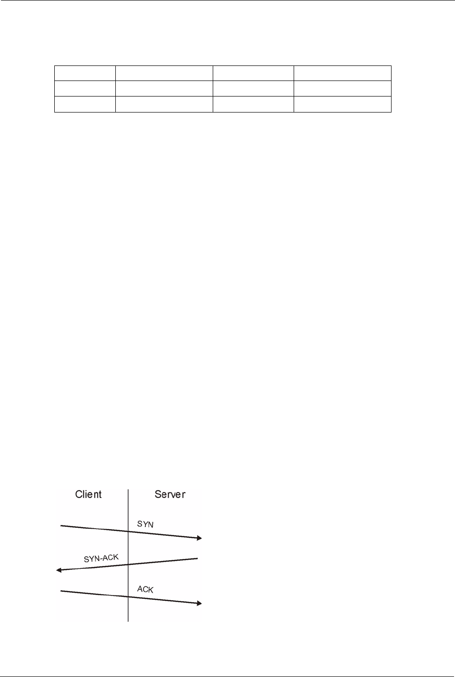
Figure 82 Three-Way Handshake
Table 52 Common IP Ports
21 FTP 53 DNS
23 Telnet 80 HTTP
25 SMTP 110 POP3
P-660H/HW-D Series User’s Guide
Chapter 9 Firewalls 148
Under normal circumstances, the application that initiates a session sends a SYN
(synchronize) packet to the receiving server. The receiver sends back an ACK
(acknowledgment) packet and its own SYN, and then the initiator responds with an ACK
(acknowledgment). After this handshake, a connection is established.
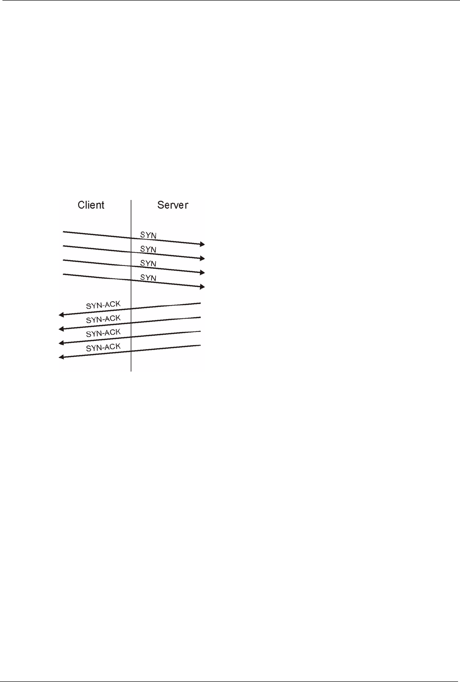
•SYN Attack floods a targeted system with a series of SYN packets. Each packet causes
the targeted system to issue a SYN-ACK response. While the targeted system waits for
the ACK that follows the SYN-ACK, it queues up all outstanding SYN-ACK responses
on what is known as a backlog queue. SYN-ACKs are moved off the queue only when an
ACK comes back or when an internal timer (which is set at relatively long intervals)
terminates the three-way handshake. Once the queue is full, the system will ignore all
incoming SYN requests, making the system unavailable for legitimate users.
Figure 83 SYN Flood
•In a LAND Attack, hackers flood SYN packets into the network with a spoofed source
IP address of the targeted system. This makes it appear as if the host computer sent the
packets to itself, making the system unavailable while the target system tries to respond
to itself.
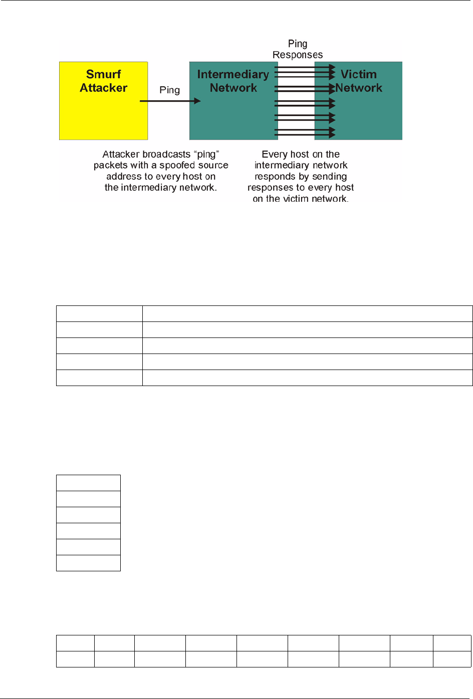
7A brute-force attack, such as a "Smurf" attack, targets a feature in the IP specification
known as directed or subnet broadcasting, to quickly flood the target network with
useless data. A Smurf hacker floods a router with Internet Control Message Protocol
(ICMP) echo request packets (pings). Since the destination IP address of each packet is
the broadcast address of the network, the router will broadcast the ICMP echo request
packet to all hosts on the network. If there are numerous hosts, this will create a large
amount of ICMP echo request and response traffic. If a hacker chooses to spoof the
source IP address of the ICMP echo request packet, the resulting ICMP traffic will not
only clog up the "intermediary" network, but will also congest the network of the spoofed
source IP address, known as the "victim" network. This flood of broadcast traffic
consumes all available bandwidth, making communications impossible.
P-660H/HW-D Series User’s Guide
149 Chapter 9 Firewalls
Figure 84 Smurf Attack
9.4.2.1 ICMP Vulnerability
ICMP is an error-reporting protocol that works in concert with IP. The following ICMP types
trigger an alert:
9.4.2.2 Illegal Commands (NetBIOS and SMTP)
The only legal NetBIOS commands are the following - all others are illegal.
All SMTP commands are illegal except for those displayed in the following tables.
Table 53 ICMP Commands That Trigger Alerts
5REDIRECT
13 TIMESTAMP_REQUEST
14 TIMESTAMP_REPLY
17 ADDRESS_MASK_REQUEST
18 ADDRESS_MASK_REPLY
Table 54 Legal NetBIOS Commands
MESSAGE:
REQUEST:
POSITIVE:
VE:
RETARGET:
KEEPALIVE:
Table 55 Legal SMTP Commands
AUTH DATA EHLO ETRN EXPN HELO HELP MAIL NOOP
QUIT RCPT RSET SAML SEND SOML TURN VRFY
P-660H/HW-D Series User’s Guide
Chapter 9 Firewalls 150
9.4.2.3 Traceroute
Traceroute is a utility used to determine the path a packet takes between two endpoints.
Sometimes when a packet filter firewall is configured incorrectly an attacker can traceroute
the firewall gaining knowledge of the network topology inside the firewall.
Often, many DoS attacks also employ a technique known as "IP Spoofing" as part of their
attack. IP Spoofing may be used to break into systems, to hide the hacker's identity, or to
magnify the effect of the DoS attack. IP Spoofing is a technique used to gain unauthorized
access to computers by tricking a router or firewall into thinking that the communications are
coming from within the trusted network. To engage in IP spoofing, a hacker must modify the
packet headers so that it appears that the packets originate from a trusted host and should be
allowed through the router or firewall. The ZyXEL Device blocks all IP Spoofing attempts.
9.5 Stateful Inspection
With stateful inspection, fields of the packets are compared to packets that are already known
to be trusted. For example, if you access some outside service, the proxy server remembers
things about your original request, like the port number and source and destination addresses.
This “remembering” is called saving the state. When the outside system responds to your
request, the firewall compares the received packets with the saved state to determine if they
are allowed in. The ZyXEL Device uses stateful packet inspection to protect the private LAN
from hackers and vandals on the Internet. By default, the ZyXEL Device’s stateful inspection
allows all communications to the Internet that originate from the LAN, and blocks all traffic to
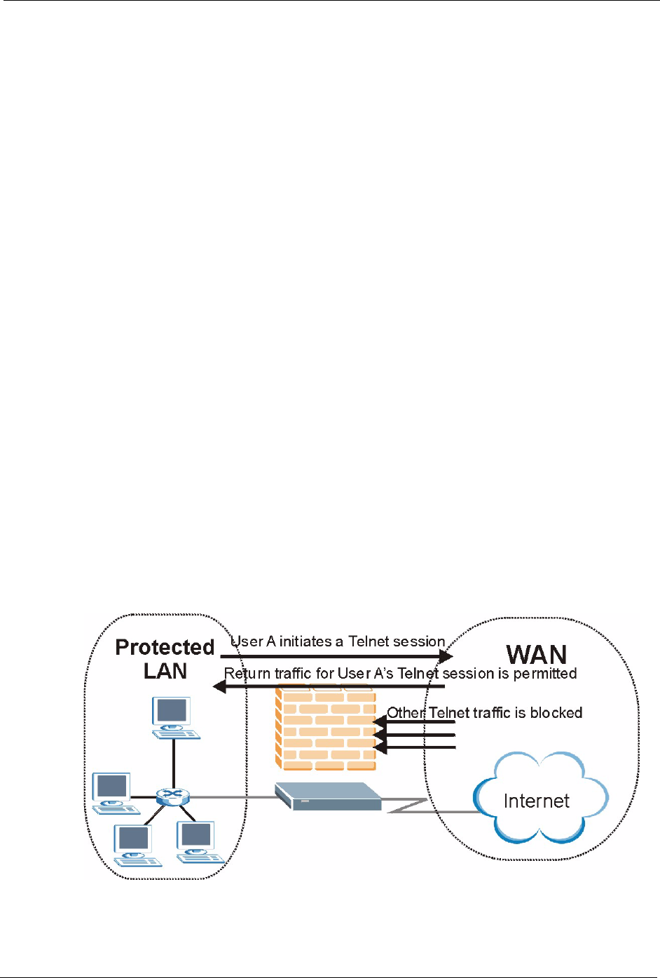
the LAN that originates from the Internet. In summary, stateful inspection:
• Allows all sessions originating from the LAN (local network) to the WAN (Internet).
• Denies all sessions originating from the WAN to the LAN.
Figure 85 Stateful Inspection

P-660H/HW-D Series User’s Guide
151 Chapter 9 Firewalls
The previous figure shows the ZyXEL Device’s default firewall rules in action as well as
demonstrates how stateful inspection works. User A can initiate a Telnet session from within
the LAN and responses to this request are allowed. However other Telnet traffic initiated from
the WAN is blocked.
9.5.1 Stateful Inspection Process
In this example, the following sequence of events occurs when a TCP packet leaves the LAN
network through the firewall's WAN interface. The TCP packet is the first in a session, and the
packet's application layer protocol is configured for a firewall rule inspection:
1The packet travels from the firewall's LAN to the WAN.
2The packet is evaluated against the interface's existing outbound access list, and the
packet is permitted (a denied packet would simply be dropped at this point).
3The packet is inspected by a firewall rule to determine and record information about the
state of the packet's connection. This information is recorded in a new state table entry
created for the new connection. If there is not a firewall rule for this packet and it is not an
attack, then the settings in the Firewall General screen determine the action for this
packet.
4Based on the obtained state information, a firewall rule creates a temporary access list
entry that is inserted at the beginning of the WAN interface's inbound extended access
list. This temporary access list entry is designed to permit inbound packets of the same
connection as the outbound packet just inspected.
5The outbound packet is forwarded out through the interface.
6Later, an inbound packet reaches the interface. This packet is part of the connection
previously established with the outbound packet. The inbound packet is evaluated against
the inbound access list, and is permitted because of the temporary access list entry
previously created.
7The packet is inspected by a firewall rule, and the connection's state table entry is updated
as necessary. Based on the updated state information, the inbound extended access list
temporary entries might be modified, in order to permit only packets that are valid for the
current state of the connection.
8Any additional inbound or outbound packets that belong to the connection are inspected
to update the state table entry and to modify the temporary inbound access list entries as
required, and are forwarded through the interface.
9When the connection terminates or times out, the connection's state table entry is deleted
and the connection's temporary inbound access list entries are deleted.
9.5.2 Stateful Inspection and the ZyXEL Device
Additional rules may be defined to extend or override the default rules. For example, a rule
may be created which will:
• Block all traffic of a certain type, such as IRC (Internet Relay Chat), from the LAN to the
Internet.

P-660H/HW-D Series User’s Guide
Chapter 9 Firewalls 152
• Allow certain types of traffic from the Internet to specific hosts on the LAN.
• Allow access to a Web server to everyone but competitors.
• Restrict use of certain protocols, such as Telnet, to authorized users on the LAN.
These custom rules work by evaluating the network traffic’s Source IP address, Destination IP
address, IP protocol type, and comparing these to rules set by the administrator.
Note: The ability to define firewall rules is a very powerful tool. Using custom rules, it
is possible to disable all firewall protection or block all access to the Internet.
Use extreme caution when creating or deleting firewall rules. Test changes
after creating them to make sure they work correctly.
Below is a brief technical description of how these connections are tracked. Connections may
either be defined by the upper protocols (for instance, TCP), or by the ZyXEL Device itself (as
with the "virtual connections" created for UDP and ICMP).
9.5.3 TCP Security
The ZyXEL Device uses state information embedded in TCP packets. The first packet of any
new connection has its SYN flag set and its ACK flag cleared; these are "initiation" packets.
All packets that do not have this flag structure are called "subsequent" packets, since they
represent data that occurs later in the TCP stream.
If an initiation packet originates on the WAN, this means that someone is trying to make a
connection from the Internet into the LAN. Except in a few special cases (see "Upper Layer
Protocols" shown next), these packets are dropped and logged.
If an initiation packet originates on the LAN, this means that someone is trying to make a
connection from the LAN to the Internet. Assuming that this is an acceptable part of the
security policy (as is the case with the default policy), the connection will be allowed. A cache
entry is added which includes connection information such as IP addresses, TCP ports,
sequence numbers, etc.
When the ZyXEL Device receives any subsequent packet (from the Internet or from the LAN),
its connection information is extracted and checked against the cache. A packet is only
allowed to pass through if it corresponds to a valid connection (that is, if it is a response to a
connection which originated on the LAN).
9.5.4 UDP/ICMP Security
UDP and ICMP do not themselves contain any connection information (such as sequence
numbers). However, at the very minimum, they contain an IP address pair (source and
destination). UDP also contains port pairs, and ICMP has type and code information. All of
this data can be analyzed in order to build "virtual connections" in the cache.
For instance, any UDP packet that originates on the LAN will create a cache entry. Its IP
address and port pairs will be stored. For a short period of time, UDP packets from the WAN
that have matching IP and UDP information will be allowed back in through the firewall.

P-660H/HW-D Series User’s Guide
153 Chapter 9 Firewalls
A similar situation exists for ICMP, except that the ZyXEL Device is even more restrictive.
Specifically, only outgoing echoes will allow incoming echo replies, outgoing address mask
requests will allow incoming address mask replies, and outgoing timestamp requests will
allow incoming timestamp replies. No other ICMP packets are allowed in through the firewall,
simply because they are too dangerous and contain too little tracking information. For
instance, ICMP redirect packets are never allowed in, since they could be used to reroute
traffic through attacking machines.
9.5.5 Upper Layer Protocols
Some higher layer protocols (such as FTP and RealAudio) utilize multiple network
connections simultaneously. In general terms, they usually have a "control connection" which
is used for sending commands between endpoints, and then "data connections" which are used
for transmitting bulk information.
Consider the FTP protocol. A user on the LAN opens a control connection to a server on the
Internet and requests a file. At this point, the remote server will open a data connection from
the Internet. For FTP to work properly, this connection must be allowed to pass through even
though a connection from the Internet would normally be rejected.
In order to achieve this, the ZyXEL Device inspects the application-level FTP data.
Specifically, it searches for outgoing "PORT" commands, and when it sees these, it adds a
cache entry for the anticipated data connection. This can be done safely, since the PORT
command contains address and port information, which can be used to uniquely identify the
connection.
Any protocol that operates in this way must be supported on a case-by-case basis. You can use
the web configurator’s Custom Ports feature to do this.
9.6 Guidelines for Enhancing Security with Your Firewall
• Change the default password via CLI (Command Line Interpreter) or web configurator.
• Limit who can telnet into your router.
• Don't enable any local service (such as SNMP or NTP) that you don't use. Any enabled
service could present a potential security risk. A determined hacker might be able to find
creative ways to misuse the enabled services to access the firewall or the network.
• For local services that are enabled, protect against misuse. Protect by configuring the
services to communicate only with specific peers, and protect by configuring rules to
block packets for the services at specific interfaces.
• Protect against IP spoofing by making sure the firewall is active.
• Keep the firewall in a secured (locked) room.
9.6.1 Security In General
You can never be too careful! Factors outside your firewall, filtering or NAT can cause
security breaches. Below are some generalizations about what you can do to minimize them.

P-660H/HW-D Series User’s Guide
Chapter 9 Firewalls 154
• Encourage your company or organization to develop a comprehensive security plan.
Good network administration takes into account what hackers can do and prepares
against attacks. The best defense against hackers and crackers is information. Educate all
employees about the importance of security and how to minimize risk. Produce lists like
this one!
• DSL or cable modem connections are “always-on” connections and are particularly
vulnerable because they provide more opportunities for hackers to crack your system.
Turn your computer off when not in use.
• Never give out a password or any sensitive information to an unsolicited telephone call or
e-mail.
• Never e-mail sensitive information such as passwords, credit card information, etc.,
without encrypting the information first.
• Never submit sensitive information via a web page unless the web site uses secure
connections. You can identify a secure connection by looking for a small “key” icon on
the bottom of your browser (Internet Explorer 3.02 or better or Netscape 3.0 or better). If
a web site uses a secure connection, it is safe to submit information. Secure web
transactions are quite difficult to crack.
• Never reveal your IP address or other system networking information to people outside
your company. Be careful of files e-mailed to you from strangers. One common way of
getting BackOrifice on a system is to include it as a Trojan horse with other files.
• Change your passwords regularly. Also, use passwords that are not easy to figure out.
The most difficult passwords to crack are those with upper and lower case letters,
numbers and a symbol such as % or #.
• Upgrade your software regularly. Many older versions of software, especially web
browsers, have well known security deficiencies. When you upgrade to the latest
versions, you get the latest patches and fixes.
• If you use “chat rooms” or IRC sessions, be careful with any information you reveal to
strangers.
• If your system starts exhibiting odd behavior, contact your ISP. Some hackers will set off
hacks that cause your system to slowly become unstable or unusable.
• Always shred confidential information, particularly about your computer, before
throwing it away. Some hackers dig through the trash of companies or individuals for
information that might help them in an attack.
9.7 Packet Filtering Vs Firewall
Below are some comparisons between the ZyXEL Device’s filtering and firewall functions.
9.7.1 Packet Filtering:
• The router filters packets as they pass through the router’s interface according to the filter
rules you designed.
• Packet filtering is a powerful tool, yet can be complex to configure and maintain,
especially if you need a chain of rules to filter a service.
• Packet filtering only checks the header portion of an IP packet.

P-660H/HW-D Series User’s Guide
155 Chapter 9 Firewalls
9.7.1.1 When To Use Filtering
• To block/allow LAN packets by their MAC addresses.
• To block/allow special IP packets which are neither TCP nor UDP, nor ICMP packets.
• To block/allow both inbound (WAN to LAN) and outbound (LAN to WAN) traffic
between the specific inside host/network "A" and outside host/network "B". If the filter
blocks the traffic from A to B, it also blocks the traffic from B to A. Filters can not
distinguish traffic originating from an inside host or an outside host by IP address.
• To block/allow IP trace route.
9.7.2 Firewall
• The firewall inspects packet contents as well as their source and destination addresses.
Firewalls of this type employ an inspection module, applicable to all protocols, that
understands data in the packet is intended for other layers, from the network layer (IP
headers) up to the application layer.
• The firewall performs stateful inspection. It takes into account the state of connections it
handles so that, for example, a legitimate incoming packet can be matched with the
outbound request for that packet and allowed in. Conversely, an incoming packet
masquerading as a response to a nonexistent outbound request can be blocked.
• The firewall uses session filtering, i.e., smart rules, that enhance the filtering process and
control the network session rather than control individual packets in a session.
• The firewall provides e-mail service to notify you of routine reports and when alerts
occur.
9.7.2.1 When To Use The Firewall
• To prevent DoS attacks and prevent hackers cracking your network.
• A range of source and destination IP addresses as well as port numbers can be specified
within one firewall rule making the firewall a better choice when complex rules are
required.
• To selectively block/allow inbound or outbound traffic between inside host/networks and
outside host/networks. Remember that filters can not distinguish traffic originating from
an inside host or an outside host by IP address.
• The firewall performs better than filtering if you need to check many rules.
• Use the firewall if you need routine e-mail reports about your system or need to be alerted
when attacks occur.
• The firewall can block specific URL traffic that might occur in the future. The URL can
be saved in an Access Control List (ACL) database.

P-660H/HW-D Series User’s Guide
Chapter 10 Firewall Configuration 156
CHAPTER 10
Firewall Configuration
This chapter shows you how to enable and configure the ZyXEL Device firewall.
10.1 Access Methods
The web configurator is, by far, the most comprehensive firewall configuration tool your
ZyXEL Device has to offer. For this reason, it is recommended that you configure your
firewall using the web configurator.CLI (Command Line Interpreter) commands provide
limited configuration options and are only recommended for advanced users.
10.2 Firewall Policies Overview
Firewall rules are grouped based on the direction of travel of packets to which they apply:
Note: The LAN includes both the LAN port and the WLAN.
By default, the ZyXEL Device’s stateful packet inspection allows packets traveling in the
following directions:
• LAN to LAN/ Router
This allows computers on the LAN to manage the ZyXEL Device and communicate
between networks or subnets connected to the LAN interface.
• LAN to WAN
By default, the ZyXEL Device’s stateful packet inspection drops packets traveling in the
following directions:
•WAN to LAN
•WAN to WAN/ Router
This prevents computers on the WAN from using the ZyXEL Device as a gateway to
communicate with other computers on the WAN and/or managing the ZyXEL Device.
You may define additional rules and sets or modify existing ones but please exercise
extreme caution in doing so.
• LAN to LAN/ Router • WAN to LAN
• LAN to WAN • WAN to WAN/ Router

P-660H/HW-D Series User’s Guide
157 Chapter 10 Firewall Configuration
Note: If you configure firewall rules without a good understanding of how they work,
you might inadvertently introduce security risks to the firewall and to the
protected network. Make sure you test your rules after you configure them.
For example, you may create rules to:
• Block certain types of traffic, such as IRC (Internet Relay Chat), from the LAN to the
Internet.
• Allow certain types of traffic, such as Lotus Notes database synchronization, from
specific hosts on the Internet to specific hosts on the LAN.
• Allow everyone except your competitors to access a Web server.
• Restrict use of certain protocols, such as Telnet, to authorized users on the LAN.
These custom rules work by comparing the Source IP address, Destination IP address and IP
protocol type of network traffic to rules set by the administrator. Your customized rules take
precedence and override the ZyXEL Device’s default rules.
10.3 Rule Logic Overview
Note: Study these points carefully before configuring rules.
10.3.1 Rule Checklist
State the intent of the rule. For example, “This restricts all IRC access from the LAN to the
Internet.” Or, “This allows a remote Lotus Notes server to synchronize over the Internet to an
inside Notes server.”
1Is the intent of the rule to forward or block traffic?
2What direction of traffic does the rule apply to?
3What IP services will be affected?
4What computers on the LAN are to be affected (if any)?
5What computers on the Internet will be affected? The more specific, the better. For
example, if traffic is being allowed from the Internet to the LAN, it is better to allow only
certain machines on the Internet to access the LAN.
10.3.2 Security Ramifications
1Once the logic of the rule has been defined, it is critical to consider the security
ramifications created by the rule:
2Does this rule stop LAN users from accessing critical resources on the Internet? For
example, if IRC is blocked, are there users that require this service?
3Is it possible to modify the rule to be more specific? For example, if IRC is blocked for all
users, will a rule that blocks just certain users be more effective?