ZyXEL Communications P660HWD1V2 802.11g WIRELESS ADSL2+ 4-PORT GATEWAY User Manual P 660H HW W T Series V3 40 User s Guide
ZyXEL Communications Corporation 802.11g WIRELESS ADSL2+ 4-PORT GATEWAY P 660H HW W T Series V3 40 User s Guide
Contents
users manual 6

P-660H/HW-D Series User’s Guide
Chapter 18 Logs 236
18.3.1 Example E-mail Log
An "End of Log" message displays for each mail in which a complete log has been sent. The
following is an example of a log sent by e-mail.
• You may edit the subject title.
• The date format here is Day-Month-Year.
• The date format here is Month-Day-Year. The time format is Hour-Minute-Second.
•"
End of Log" message shows that a complete log has been sent.
Figure 138 E-mail Log Example
Subject:
Firewall Alert From xxxxx
Date:
Fri, 07 Apr 2000 10:05:42
From:
user@zyxel.com
To:
user@zyxel.com
1|Apr 7 00 |From:192.168.1.1 To:192.168.1.255 |default policy |forward
| 09:54:03 |UDP src port:00520 dest port:00520 |<1,00> |
2|Apr 7 00 |From:192.168.1.131 To:192.168.1.255 |default policy |forward
| 09:54:17 |UDP src port:00520 dest port:00520 |<1,00> |
3|Apr 7 00 |From:192.168.1.6 To:10.10.10.10 |match |forward
| 09:54:19 |UDP src port:03516 dest port:00053 |<1,01> |
……………………………..{snip}…………………………………..
……………………………..{snip}…………………………………..
126|Apr 7 00 |From:192.168.1.1 To:192.168.1.255 |match |forward
| 10:05:00 |UDP src port:00520 dest port:00520 |<1,02> |
127|Apr 7 00 |From:192.168.1.131 To:192.168.1.255 |match |forward
| 10:05:17 |UDP src port:00520 dest port:00520 |<1,02> |
128|Apr 7 00 |From:192.168.1.1 To:192.168.1.255 |match |forward
| 10:05:30 |UDP src port:00520 dest port:00520 |<1,02> |
End of Firewall Log

P-660H/HW-D Series User’s Guide
237 Chapter 18 Logs
P-660H/HW-D Series User’s Guide
Chapter 19 Tools 238
CHAPTER 19
Tools
This chapter describes how to upload new firmware, manage configuration and restart your
ZyXEL Device.
19.1 Firmware Upgrade
Find firmware at www.zyxel.com in a file that (usually) uses the system model name with
a.bin extension, for example, "ZyXEL Device.bin". The upload process uses HTTP (Hypertext
Transfer Protocol) and may take up to two minutes. After a successful upload, the system will
reboot.
Only use firmware for your device’s specific model. Refer to the label on the bottom of your
device.
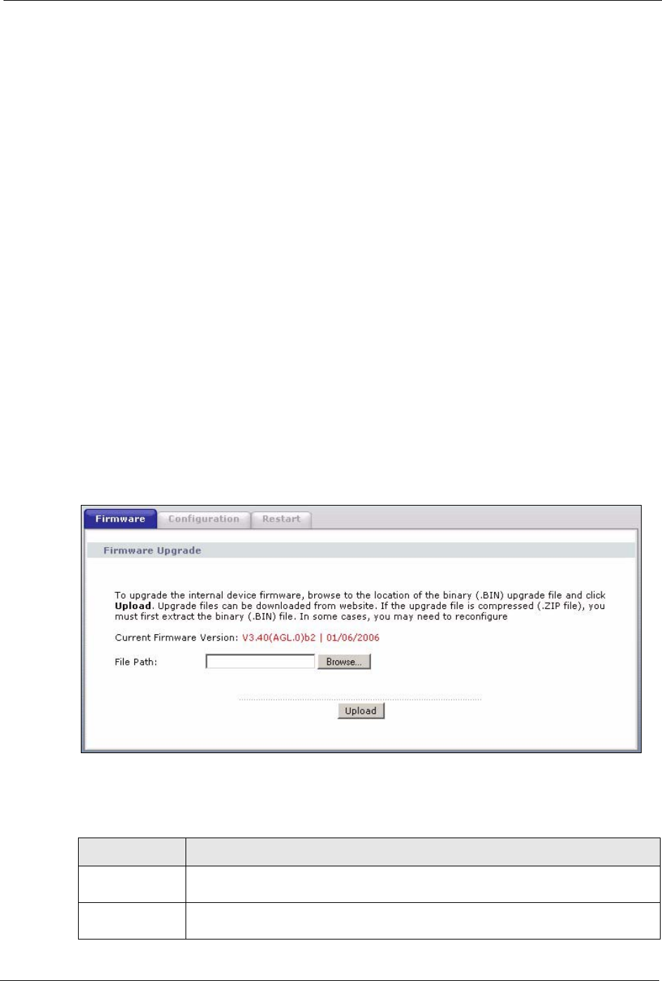
Click Maintenance > Tools to open the Firmware screen. Follow the instructions in this
screen to upload firmware to your ZyXEL Device.
Figure 139 Firmware Upgrade
The following table describes the labels in this screen.
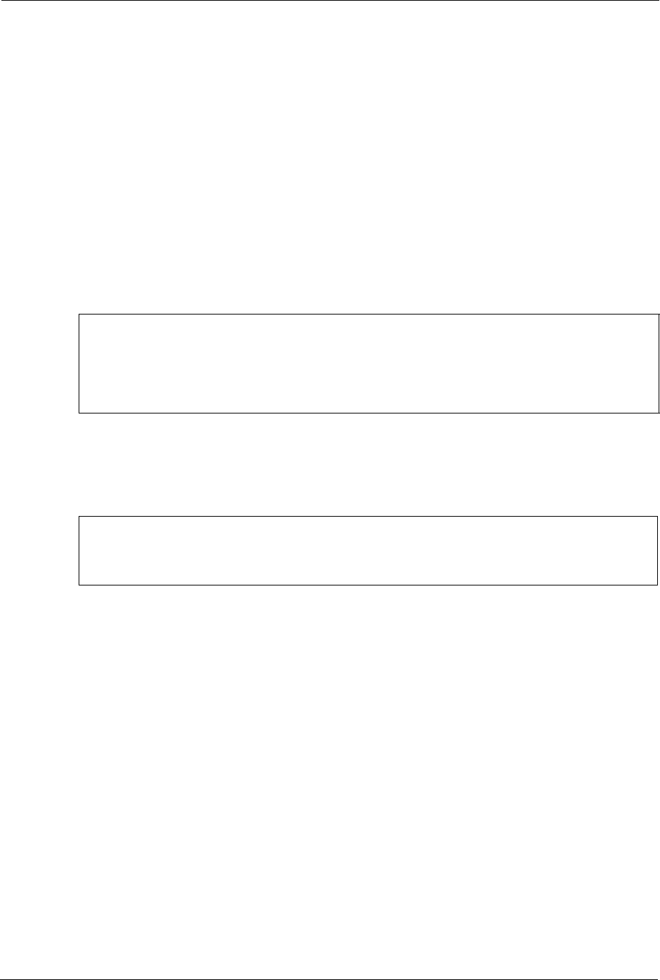
Table 93 Firmware Upgrade
LABEL DESCRIPTION
Current Firmware
Version
This is the present Firmware version and the date created.
File Path Type in the location of the file you want to upload in this field or click Browse ... to
find it.
P-660H/HW-D Series User’s Guide
239 Chapter 19 Tools
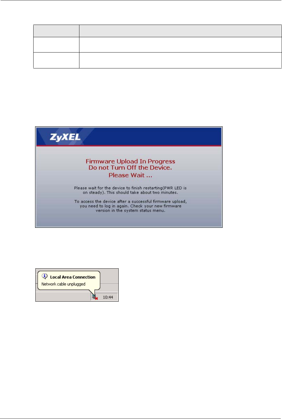
Note: Do NOT turn off the ZyXEL Device while firmware upload is in progress!
After you see the Firmware Upload in Progress screen, wait two minutes before logging into
the ZyXEL Device again.
Figure 140 Firmware Upload In Progress
The ZyXEL Device automatically restarts in this time causing a temporary network
disconnect. In some operating systems, you may see the following icon on your desktop.
Figure 141 Network Temporarily Disconnected
After two minutes, log in again and check your new firmware version in the Status screen.
If the upload was not successful, the following screen will appear. Click Return to go back to
the Firmware screen.
Browse... Click Browse... to find the .bin file you want to upload. Remember that you must
decompress compressed (.zip) files before you can upload them.
Upload Click Upload to begin the upload process. This process may take up to two
minutes.
Table 93 Firmware Upgrade (continued)
LABEL DESCRIPTION
P-660H/HW-D Series User’s Guide
Chapter 19 Tools 240
Figure 142 Error Message
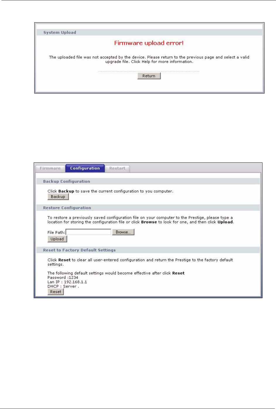
19.2 Configuration Screen
Click Maintenance > Tools > Configuration. Information related to factory defaults, backup
configuration, and restoring configuration appears as shown next.
Figure 143 Configuration
19.2.1 Backup Configuration
Backup configuration allows you to back up (save) the ZyXEL Device’s current configuration
to a file on your computer. Once your ZyXEL Device is configured and functioning properly,
it is highly recommended that you back up your configuration file before making
configuration changes. The backup configuration file will be useful in case you need to return
to your previous settings.
Click Backup to save the ZyXEL Device’s current configuration to your computer
P-660H/HW-D Series User’s Guide
241 Chapter 19 Tools
19.2.2 Restore Configuration
Restore configuration allows you to upload a new or previously saved configuration file from
your computer to your ZyXEL Device.
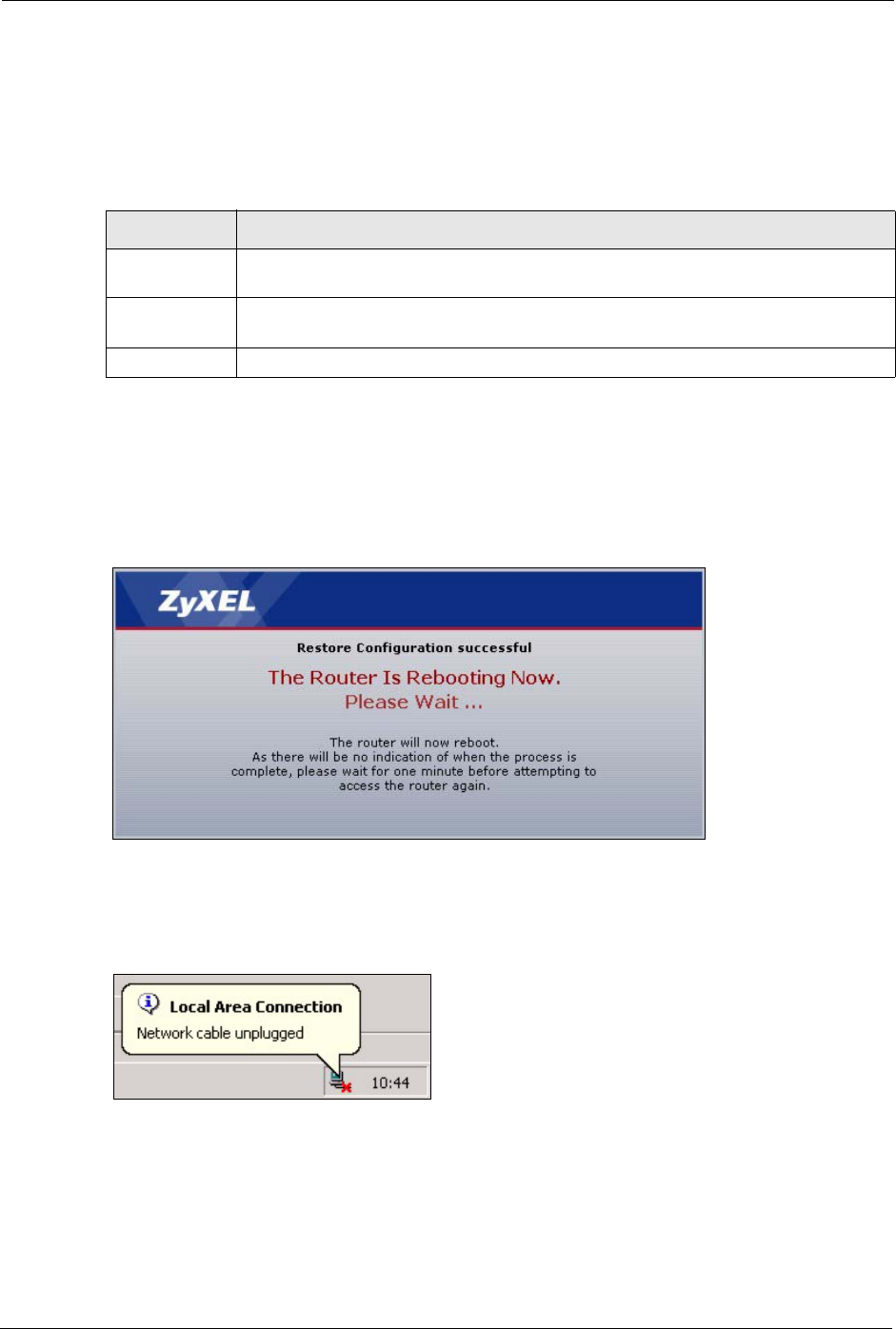
Note: Do not turn off the ZyXEL Device while configuration file upload is in progress
After you see a “Restore Configuration successful” screen, you must then wait one minute
before logging into the ZyXEL Device again.
Figure 144 Configuration Restore Successful
The ZyXEL Device automatically restarts in this time causing a temporary network
disconnect. In some operating systems, you may see the following icon on your desktop.
Figure 145 Temporarily Disconnected
If you uploaded the default configuration file you may need to change the IP address of your
computer to be in the same subnet as that of the default ZyXEL Device IP address
(192.168.1.1). See the appendix for details on how to set up your computer’s IP address.
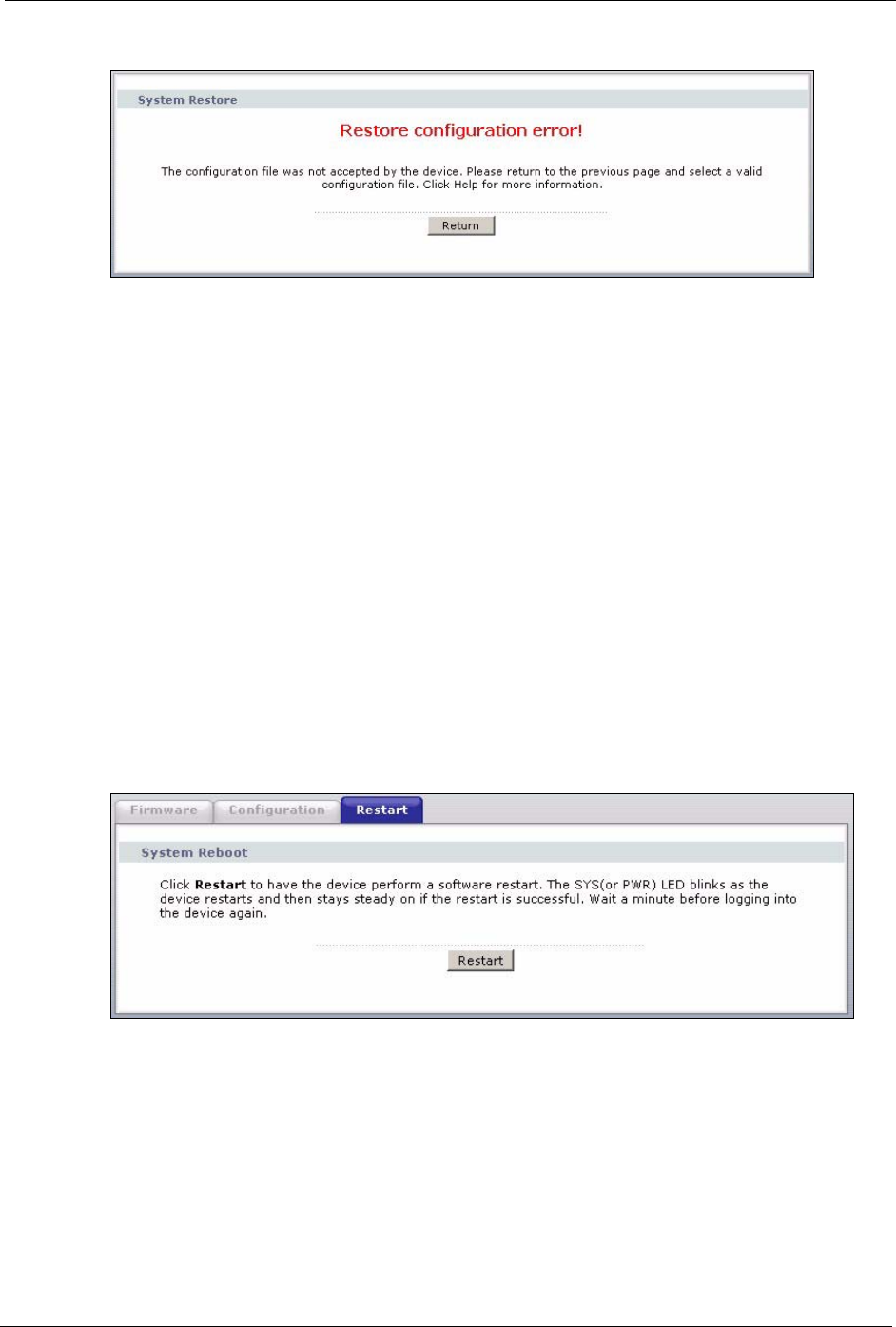
If the upload was not successful, the following screen will appear. Click Return to go back to
the Configuration screen.
Table 94 Maintenance Restore Configuration
LABEL DESCRIPTION
File Path Type in the location of the file you want to upload in this field or click Browse... to find
it.
Browse... Click Browse... to find the file you want to upload. Remember that you must
decompress compressed (.ZIP) files before you can upload them.
Upload Click Upload to begin the upload process.
P-660H/HW-D Series User’s Guide
Chapter 19 Tools 242
Figure 146 Configuration Restore Error
19.2.3 Back to Factory Defaults
Pressing the RESET button in this section clears all user-entered configuration information
and returns the ZyXEL Device to its factory defaults.
You can also press the RESET button on the rear panel to reset the factory defaults of your
ZyXEL Device. Refer to the chapter about introducing the web configurator for more
information on the RESET button.
19.3 Restart
System restart allows you to reboot the ZyXEL Device without turning the power off.
Click Maintenance > Tools > Restart. Click Restart to have the ZyXEL Device reboot. This
does not affect the ZyXEL Device's configuration.
Figure 147 Restart Screen

P-660H/HW-D Series User’s Guide
243 Chapter 19 Tools
P-660H/HW-D Series User’s Guide
Chapter 20 Diagnostic 244
CHAPTER 20
Diagnostic
These read-only screens display information to help you identify problems with the ZyXEL
Device.
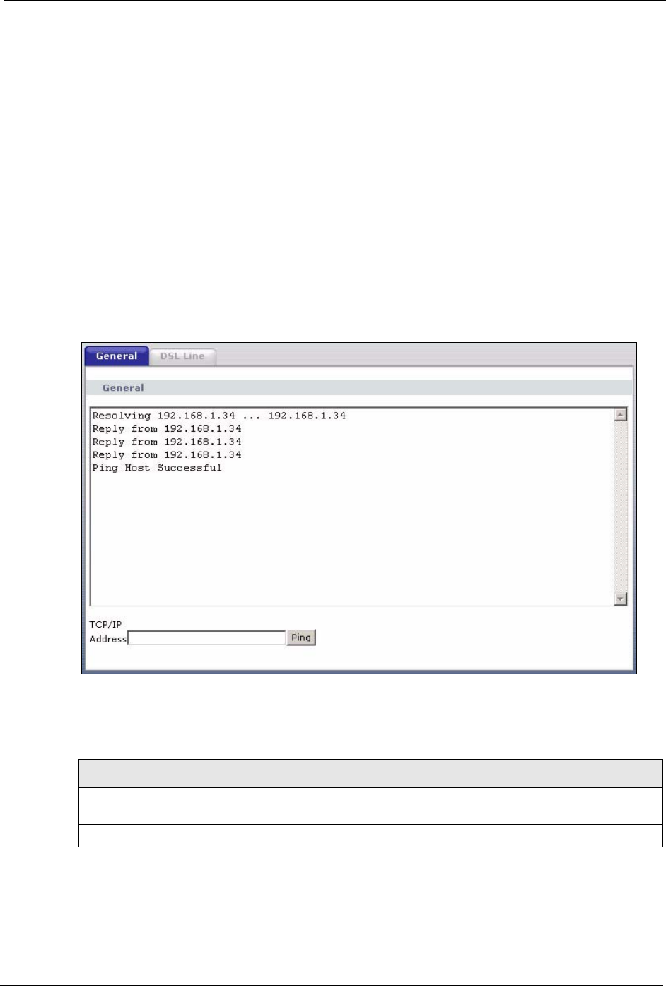
20.1 General Diagnostic
Click Maintenance > Diagnostic to open the screen shown next.
Figure 148 Diagnostic: General
The following table describes the fields in this screen.
Table 95 Diagnostic: General
LABEL DESCRIPTION
TCP/IP
Address
Type the IP address of a computer that you want to ping in order to test a connection.
Ping Click this button to ping the IP address that you entered.
P-660H/HW-D Series User’s Guide
245 Chapter 20 Diagnostic
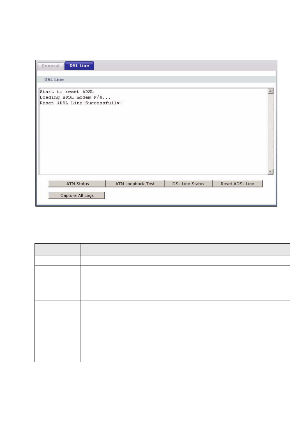
20.2 DSL Line Diagnostic
Click Maintenance > Diagnostic > DSL Line to open the screen shown next.
Figure 149 Diagnostic: DSL Line
The following table describes the fields in this screen.
Table 96 Diagnostic: DSL Line
LABEL DESCRIPTION
ATM Status Click this button to view ATM status.
ATM Loopback
Test
Click this button to start the ATM loopback test. Make sure you have configured at
least one PVC with proper VPIs/VCIs before you begin this test. The ZyXEL Device
sends an OAM F5 packet to the DSLAM/ATM switch and then returns it (loops it
back) to the ZyXEL Device. The ATM loopback test is useful for troubleshooting
problems with the DSLAM and ATM network.
DSL Line Status Click this button to view the DSL port’s line operating values and line bit allocation.
Reset ADSL
Line
Click this button to reinitialize the ADSL line. The large text box above then displays
the progress and results of this operation, for example:
"Start to reset ADSL
Loading ADSL modem F/W...
Reset ADSL Line Successfully!"
Capture All Logs Click this button to display all logs generated with the DSL line.
P-660H/HW-D Series User’s Guide
Chapter 21 Troubleshooting 246
CHAPTER 21
Troubleshooting
This chapter covers potential problems and the corresponding remedies.
21.1 Problems Starting Up the ZyXEL Device
21.2 Problems with the LAN
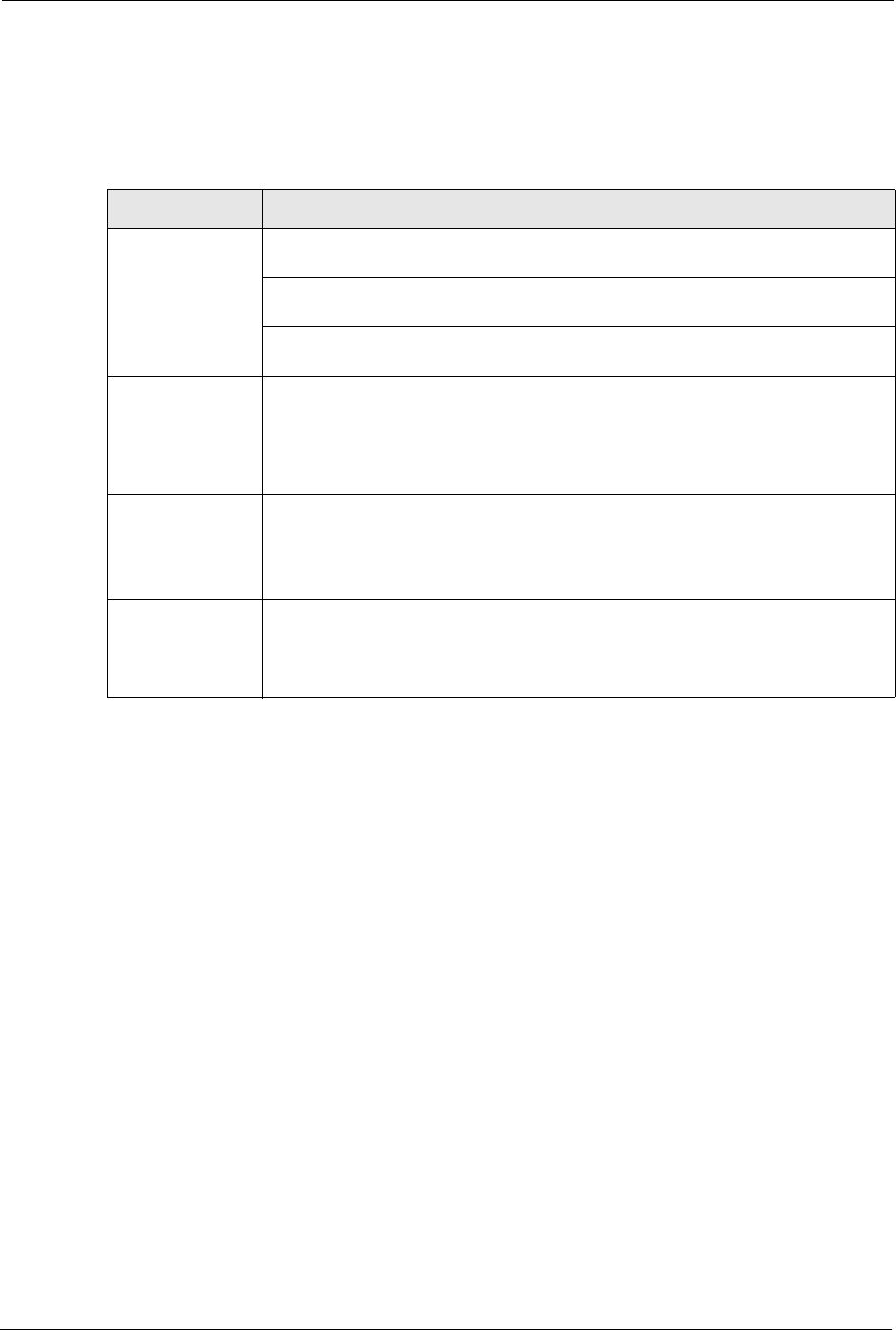
Table 97 Troubleshooting Starting Up Your ZyXEL Device
PROBLEM CORRECTIVE ACTION
None of the
LEDs turn on
when I turn on
the ZyXEL
Device.
Make sure that the ZyXEL Device’s power adaptor is connected to the ZyXEL Device
and plugged in to an appropriate power source. Make sure that the ZyXEL Device and
the power source are both turned on.
Turn the ZyXEL Device off and on.
If the error persists, you may have a hardware problem. In this case, you should
contact your vendor.
Table 98 Troubleshooting the LAN
PROBLEM CORRECTIVE ACTION
The LAN LEDs
do not turn on.
Check your Ethernet cable connections (refer to the Quick Start Guide for details).
Check for faulty Ethernet cables.
Make sure your computer’s Ethernet Card is working properly.
I cannot access
the ZyXEL
Device from the
LAN.
If Any IP is disabled, make sure that the IP address and the subnet mask of the
ZyXEL Device and your computer(s) are on the same subnet.
P-660H/HW-D Series User’s Guide
247 Chapter 21 Troubleshooting
21.3 Problems with the WAN
Table 99 Troubleshooting the WAN
PROBLEM CORRECTIVE ACTION
The DSL LED is
off.
Check the telephone wire and connections between the ZyXEL Device DSL port
and the wall jack.
Make sure that the telephone company has checked your phone line and set it up
for DSL service.
Reset your ADSL line to reinitialize your link to the DSLAM. For details, refer to the
Table 96 on page 245.
I cannot get a
WAN IP address
from the ISP.
The ISP provides the WAN IP address after authenticating you. Authentication
may be through the user name and password, the MAC address or the host name.
The username and password apply to PPPoE and PPPoA encapsulation only.
Make sure that you have entered the correct Service Type, User Name and
Password (be sure to use the correct casing). Refer to the WAN Setup chapter.
I cannot access
the Internet.
Make sure the ZyXEL Device is turned on and connected to the network.
Verify your WAN settings. Refer to the chapter on WAN setup.
Make sure you entered the correct user name and password.
If you use PPPoE pass through, make sure that bridge mode is turned on.
The Internet
connection
disconnects.
Check the schedule rules.
If you use PPPoA or PPPoE encapsulation, check the idle time-out setting. Refer
to the Chapter 5 on page 76.
Contact your ISP.

P-660H/HW-D Series User’s Guide
Chapter 21 Troubleshooting 248
21.4 Problems Accessing the ZyXEL Device
Table 100 Troubleshooting Accessing the ZyXEL Device
PROBLEM CORRECTIVE ACTION
I cannot
access the
ZyXEL Device.
The default user password is “user” and admin password is “1234”. The Password
field is case-sensitive. Make sure that you enter the correct password using the proper
case.
If you have changed the password and have now forgotten it, you will need to upload
the default configuration file. This restores all of the factory defaults including the
password.
I cannot
access the
web
configurator.
Make sure that there is not a Telnet session running.
Use the ZyXEL Device’s WAN IP address when configuring from the WAN. Refer to
the instructions on checking your WAN connection.
Use the ZyXEL Device’s LAN IP address when configuring from the LAN. Refer to for
instructions on checking your LAN connection.
Check that you have enabled web service access. If you have configured a secured
client IP address, your computer’s IP address must match it. Refer to the chapter on
remote management for details.
Your computer’s and the ZyXEL Device’s IP addresses must be on the same subnet
for LAN access.
If you changed the ZyXEL Device’s LAN IP address, then enter the new one as the
URL.
Make sure that pop-up windows, JavaScripts and Java permissions are allowed. See
the appendix for how to enable them.

P-660H/HW-D Series User’s Guide
249 Chapter 21 Troubleshooting

P-660H/HW-D Series User’s Guide
Appendix A Product Specifications 250
APPENDIX A
Product Specifications
See also the Introduction chapter for a general overview of the key features.
Specification Tables
Table 101 Device
Default IP Address 192.168.1.1
Default Subnet Mask 255.255.255.0 (24 bits)
Default Password 1234
DHCP Pool 192.168.1.33 to 192.168.1.64
Dimensions (W x D x H) 180 x 128 x 36 mm
Power Specification 12VAC 1A
Built-in Switch Four auto-negotiating, auto MDI/MDI-X 10/100 Mbps RJ-45 Ethernet ports
Operation Temperature 0º C ~ 40º C
Storage Temperature -20º ~ 60º C
Operation Humidity 20% ~ 85% RH
Storage Humidity 10% ~ 90% RH
Distance between the
centers of the holes on
the device’s back.
108 mm
Screw size for wall-
mounting
M3*10

P-660H/HW-D Series User’s Guide
251 Appendix A Product Specifications
Table 102 Firmware
ADSL Standards Multi-Mode standard (ANSI T1.413,Issue 2; G.dmt(G.992.1); G.lite(G992.2)).
ADSL2 G.dmt.bis (G.992.3)
ADSL2 G.lite.bis (G.992.4)
ADSL2+ (G.992.5)
Reach-Extended ADSL (RE ADSL)
SRA (Seamless Rate Adaptation)
Auto-negotiating rate adaptation
ADSL physical connection ATM AAL5 (ATM Adaptation Layer type 5)
Multi-protocol over AAL5 (RFC2684/1483)
PPP over ATM AAL5 (RFC 2364)
PPP over Ethernet (RFC 2516)
RFC 1483 encapsulation over ATM
MAC encapsulated routing (ENET encapsulation)
VC-based and LLC-based multiplexing
Up to 8 PVCs (Permanent Virtual Circuits)
I.610 F4/F5 OAM
Other Protocol
Support
PPP (Point-to-Point Protocol) link layer protocol.
Transparent bridging for unsupported network layer protocols.
DHCP Server/Client/Relay
RIP I/RIP II
ICMP
ATM QoS
SNMP v1 and v2c with MIB II support (RFC 1213)
IP Multicasting IGMP v1 and v2
IGMP Proxy
UPnP
Management Embedded Web Configurator
CLI (Command Line Interpreter)
Remote Management via Telnet or Web
SNMP manageable
FTP/TFTP for firmware downloading, configuration backup and restoration.
Syslog
Built-in Diagnostic Tools for FLASH memory, ADSL circuitry, RAM and LAN
port
MAP - “Multimedia Auto Provisioner” (multimedia installation tutorial and
automatic configurator)
TR-069 (P-660H-D only)
Wireless
(P-660HW-D only)
IEEE 802.11g compliance
Frequency Range: 2.4 GHz
Advanced Orthogonal Frequency Division Multiplexing (OFDM)
Data Rates: 54Mbps and Auto Fallback
Wired Equivalent Privacy (WEP) Data Encryption 64/128/256 bit
WLAN bridge to LAN
Up to 32 MAC address filters
WPA(2), WPA(2)-PSK
IEEE 802.1x
External RADIUS server using EAP-MD5, TLS, TTLS

P-660H/HW-D Series User’s Guide
Appendix A Product Specifications 252
Firewall Stateful Packet Inspection.
Prevent Denial of Service attacks such as Ping of Death, SYN Flood, LAND,
Smurf etc.
Real time E-mail alerts.
Reports and logs.
NAT/SUA Port Forwarding
1024 NAT sessions
Multimedia application
PPTP under NAT/SUA
IPSec passthrough
SIP ALG passthrough
VPN passthrough
Content Filtering Web page blocking by URL keyword.
Static Routes 16 IP and 4 Bridge
Other Features Any IP
Zero Configuration (VC auto-hunting)
Traffic Redirect
Dynamic DNS
IP Alias
MBM (Multimedia Bandwidth Management) QoS (Quality of Service)
Table 102 Firmware (continued)

P-660H/HW-D Series User’s Guide
253 Appendix A Product Specifications

P-660H/HW-D Series User’s Guide
Appendix B About ADSL 254
APPENDIX B
About ADSL
Introduction to DSL
DSL (Digital Subscriber Line) technology enhances the data capacity of the existing twisted-
pair wire that runs between the local telephone company switching offices and most homes
and offices. While the wire itself can handle higher frequencies, the telephone switching
equipment is designed to cut off signals above 4,000 Hz to filter noise off the voice line, but
now everybody is searching for ways to get more bandwidth to improve access to the Web -
hence DSL technologies.
There are actually seven types of DSL service, ranging in speeds from 16 Kbits/sec to 52
Mbits/sec. The services are either symmetrical (traffic flows at the same speed in both
directions), or asymmetrical (the downstream capacity is higher than the upstream capacity).
Asymmetrical services (ADSL) are suitable for Internet users because more information is
usually downloaded than uploaded. For example, a simple button click in a web browser can
start an extended download that includes graphics and text.
As data rates increase, the carrying distance decreases. That means that users who are beyond
a certain distance from the telephone company’s central office may not be able to obtain the
higher speeds.
A DSL connection is a point-to-point dedicated circuit, meaning that the link is always up and
there is no dialing required.
ADSL Overview
Asynchronous Digital Subscriber Line (ADSL) technology provides high-speed data access
across regular telephone or ISDN lines by making use of previously unused high-frequency
bandwidth. ADSL is asymmetric in the sense that it provides a higher downstream data rate
transfer (up to 8Mbps), than in the upstream transfer (up to 832 Kbps). Asymmetric operation
is ideal for typical home and small office use where files and information are downloaded
more frequently than uploaded.
Advantages of ADSL
1ADSL provides a private (unlike cable telephone and modem services where the line is
shared), dedicated and secure channel of communications between you and your service
provider.

P-660H/HW-D Series User’s Guide
255 Appendix B About ADSL
2Because your line is dedicated (not shared), transmission speeds between you and the
device to which you connect at your service provider are not affected by other users. With
cable modems, transmission speeds drop significantly as more users go on-line because
the line is shared.
3ADSL can be "always on" (connected). This means that there is no time wasted dialing up
the service several times a day and waiting to be connected; ADSL is on standby, ready
for use whenever you need it.

P-660H/HW-D Series User’s Guide
Appendix C Internal SPTGEN 256
APPENDIX C
Internal SPTGEN
This appendix introduces Internal SPTGEN. All menus shown in this appendix are example
menus meant to show SPTGEN usage. Actual menus for your product may differ.
Internal SPTGEN Overview
Internal SPTGEN (System Parameter Table Generator) is a configuration text file useful for
efficient configuration of multiple ZyXEL Devices. Internal SPTGEN lets you configure, save
and upload multiple menus at the same time using just one configuration text file – eliminating
the need to navigate and configure individual screens for each ZyXEL Device. You can use
FTP to get the Internal SPTGEN file. Then edit the file in a text editor and use FTP to upload
it again to the same device or another one. See the following sections for details.
The Configuration Text File Format
All Internal SPTGEN text files conform to the following format:
<field identification number = field name = parameter values
allowed = input>,
where <input> is your input conforming to <parameter values allowed>.
The figure shown next is an example of an Internal SPTGEN text file.
Figure 150 Configuration Text File Format: Column Descriptions
Note: DO NOT alter or delete any field except parameters in the Input column.
This appendix introduces Internal SPTGEN. All menus shown in this appendix are example
menus meant to show SPTGEN usage. Actual menus for your product may differ.
/ Menu 1 General Setup
10000000 = Configured <0(No)| 1(Yes)> = 1
10000001 = System Name <Str> = Your Device
10000002 = Location <Str> =
10000003 = Contact Person’s Name <Str> =
10000004 = Route IP <0(No)| 1(Yes)> = 1
10000005 = Route IPX <0(No)| 1(Yes)> = 0
10000006 = Bridge <0(No)| 1(Yes)> = 0
P-660H/HW-D Series User’s Guide
257 Appendix C Internal SPTGEN
Internal SPTGEN File Modification - Important Points to Remember
Each parameter you enter must be preceded by one “=”sign and one space.
Some parameters are dependent on others. For example, if you disable the Configured field in
menu 1 (see Figure 150 on page 256), then you disable every field in this menu.
If you enter a parameter that is invalid in the Input column, the ZyXEL Device will not save
the configuration and the command line will display the Field Identification Number. Figure
151 on page 257, shown next, is an example of what the ZyXEL Device displays if you enter a
value other than “0” or “1” in the Input column of Field Identification Number 1000000
(refer to Figure 150 on page 256).
Figure 151 Invalid Parameter Entered: Command Line Example
The ZyXEL Device will display the following if you enter parameter(s) that are valid.
Figure 152 Valid Parameter Entered: Command Line Example
Internal SPTGEN FTP Download Example
1Launch your FTP application.
2Enter "bin". The command “bin” sets the transfer mode to binary.
3Get "rom-t" file. The command “get” transfers files from the ZyXEL Device to your
computer. The name “rom-t” is the configuration filename on the ZyXEL Device.
4Edit the "rom-t" file using a text editor (do not use a word processor). You must leave
this FTP screen to edit.
field value is not legal error:-1
ROM-t is not saved, error Line ID:10000000
reboot to get the original configuration
Bootbase Version: V2.02 | 2/22/2001 13:33:11
RAM: Size = 8192 Kbytes
FLASH: Intel 8M *2
Please wait for the system to write SPT text file(ROM-t)...
Bootbase Version: V2.02 | 2/22/2001 13:33:11
RAM: Size = 8192 Kbytes
FLASH: Intel 8M *2

P-660H/HW-D Series User’s Guide
Appendix C Internal SPTGEN 258
Figure 153 Internal SPTGEN FTP Download Example
Note: You can rename your “rom-t” file when you save it to your computer but it must
be named “rom-t” when you upload it to your ZyXEL Device.
Internal SPTGEN FTP Upload Example
1Launch your FTP application.
2Enter "bin". The command “bin” sets the transfer mode to binary.
3Upload your “rom-t” file from your computer to the ZyXEL Device using the “put”
command. computer to the ZyXEL Device.
4Exit this FTP application.
Figure 154 Internal SPTGEN FTP Upload Example
c:\ftp 192.168.1.1
220 PPP FTP version 1.0 ready at Sat Jan 1 03:22:12 2000
User (192.168.1.1:(none)):
331 Enter PASS command
Password:
230 Logged in
ftp>bin
200 Type I OK
ftp> get rom-t
ftp>bye
c:\edit rom-t
(edit the rom-t text file by a text editor and save it)
c:\ftp 192.168.1.1
220 PPP FTP version 1.0 ready at Sat Jan 1 03:22:12 2000
User (192.168.1.1:(none)):
331 Enter PASS command
Password:
230 Logged in
ftp>bin
200 Type I OK
ftp> put rom-t
ftp>bye
P-660H/HW-D Series User’s Guide
259 Appendix C Internal SPTGEN
Example Internal SPTGEN Menus
This section provides example Internal SPTGEN menus.
Table 103 Abbreviations Used in the Example Internal SPTGEN Screens Table
ABBREVIATION MEANING
FIN Field Identification Number
FN Field Name
PVA Parameter Values Allowed
INPUT An example of what you may enter
* Applies to the ZyXEL Device.
Table 104 Menu 1 General Setup
/ Menu 1 General Setup
FIN FN PVA INPUT
10000000 = Configured <0(No) | 1(Yes)> = 0
10000001 = System Name <Str> = Your Device
10000002 = Location <Str> =
10000003 = Contact Person's Name <Str> =
10000004 = Route IP <0(No) | 1(Yes)> = 1
10000006 = Bridge <0(No) | 1(Yes)> = 0
Table 105 Menu 3
/ Menu 3.1 General Ethernet Setup
FIN FN PVA INPUT
30100001 = Input Protocol filters Set 1 = 2
30100002 = Input Protocol filters Set 2 = 256
30100003 = Input Protocol filters Set 3 = 256
30100004 = Input Protocol filters Set 4 = 256
30100005 = Input device filters Set 1 = 256
30100006 = Input device filters Set 2 = 256
30100007 = Input device filters Set 3 = 256
30100008 = Input device filters Set 4 = 256
30100009 = Output protocol filters Set 1 = 256
30100010 = Output protocol filters Set 2 = 256
30100011 = Output protocol filters Set 3 = 256

P-660H/HW-D Series User’s Guide
Appendix C Internal SPTGEN 260
30100012 = Output protocol filters Set 4 = 256
30100013 = Output device filters Set 1 = 256
30100014 = Output device filters Set 2 = 256
30100015 = Output device filters Set 3 = 256
30100016 = Output device filters Set 4 = 256
/ Menu 3.2 TCP/IP and DHCP Ethernet Setup
FIN FN PVA INPUT
30200001 = DHCP <0(None) |
1(Server) |
2(Relay)>
= 0
30200002 = Client IP Pool Starting Address =
192.168.1.33
30200003 = Size of Client IP Pool = 32
30200004 = Primary DNS Server = 0.0.0.0
30200005 = Secondary DNS Server = 0.0.0.0
30200006 = Remote DHCP Server = 0.0.0.0
30200008 = IP Address =
172.21.2.200
30200009 = IP Subnet Mask = 16
30200010 = RIP Direction <0(None) |
1(Both) | 2(In
Only) | 3(Out
Only)>
= 0
30200011 = Version <0(Rip-1) |
1(Rip-2B)
|2(Rip-2M)>
= 0
30200012 = Multicast <0(IGMP-v2) |
1(IGMP-v1) |
2(None)>
= 2
30200013 = IP Policies Set 1 (1~12) = 256
30200014 = IP Policies Set 2 (1~12) = 256
30200015 = IP Policies Set 3 (1~12) = 256
30200016 = IP Policies Set 4 (1~12) = 256
/ Menu 3.2.1 IP Alias Setup
FIN FN PVA INPUT
30201001 = IP Alias 1 <0(No) |
1(Yes)>
= 0
30201002 = IP Address = 0.0.0.0
30201003 = IP Subnet Mask = 0
30201004 = RIP Direction <0(None) |
1(Both) | 2(In
Only) | 3(Out
Only)>
= 0
Table 105 Menu 3

P-660H/HW-D Series User’s Guide
261 Appendix C Internal SPTGEN
30201005 = Version <0(Rip-1) |
1(Rip-2B)
|2(Rip-2M)>
= 0
30201006 = IP Alias #1 Incoming protocol filters
Set 1
= 256
30201007 = IP Alias #1 Incoming protocol filters
Set 2
= 256
30201008 = IP Alias #1 Incoming protocol filters
Set 3
= 256
30201009 = IP Alias #1 Incoming protocol filters
Set 4
= 256
30201010 = IP Alias #1 Outgoing protocol filters
Set 1
= 256
30201011 = IP Alias #1 Outgoing protocol filters
Set 2
= 256
30201012 = IP Alias #1 Outgoing protocol filters
Set 3
= 256
30201013 = IP Alias #1 Outgoing protocol filters
Set 4
= 256
30201014 = IP Alias 2 <0(No) | 1(Yes)> = 0
30201015 = IP Address = 0.0.0.0
30201016 = IP Subnet Mask = 0
30201017 = RIP Direction <0(None) |
1(Both) | 2(In
Only) | 3(Out
Only)>
= 0
30201018 = Version <0(Rip-1) |
1(Rip-2B)
|2(Rip-2M)>
= 0
30201019 = IP Alias #2 Incoming protocol filters
Set 1
= 256
30201020 = IP Alias #2 Incoming protocol filters
Set 2
= 256
30201021 = IP Alias #2 Incoming protocol filters
Set 3
= 256
30201022 = IP Alias #2 Incoming protocol filters
Set 4
= 256
30201023 = IP Alias #2 Outgoing protocol filters
Set 1
= 256
30201024 = IP Alias #2 Outgoing protocol filters
Set 2
= 256
30201025 = IP Alias #2 Outgoing protocol filters
Set 3
= 256
30201026 = IP Alias #2 Outgoing protocol filters
Set 4
= 256
*/ Menu 3.5 Wireless LAN Setup
Table 105 Menu 3

P-660H/HW-D Series User’s Guide
Appendix C Internal SPTGEN 262
FIN FN PVA INPUT
30500001 = ESSID Wireless
30500002 = Hide ESSID <0(No) |
1(Yes)>
= 0
30500003 = Channel ID <1|2|3|4|5|6|7
|8|9|10|11|12|
13>
= 1
30500004 = RTS Threshold <0 ~ 2432> = 2432
30500005 = FRAG. Threshold <256 ~ 2432> = 2432
30500006 = WEP <0(DISABLE) |
1(64-bit WEP)
| 2(128-bit
WEP)>
= 0
30500007 = Default Key <1|2|3|4> = 0
30500008 = WEP Key1 =
30500009 = WEP Key2 =
30500010 = WEP Key3 =
30500011 = WEP Key4 =
30500012 = Wlan Active <0(Disable) |
1(Enable)>
= 0
30500013 = Wlan 4X Mode <0(Disable) |
1(Enable)>
= 0
*/ MENU 3.5.1 WLAN MAC ADDRESS FILTER
FIN FN PVA INPUT
30501001 = Mac Filter Active <0(No) |
1(Yes)>
= 0
30501002 = Filter Action <0(Allow) |
1(Deny)>
= 0
30501003 = Address 1 =
00:00:00:00:0
0:00
30501004 = Address 2 =
00:00:00:00:0
0:00
30501005 = Address 3 =
00:00:00:00:0
0:00
Continued … …
30501034 = Address 32 =
00:00:00:00:0
0:00
Table 105 Menu 3

P-660H/HW-D Series User’s Guide
263 Appendix C Internal SPTGEN
Table 106 Menu 4 Internet Access Setup
/ Menu 4 Internet Access Setup
FIN FN PVA INPUT
40000000 = Configured <0(No) |
1(Yes)>
= 1
40000001 = ISP <0(No) |
1(Yes)>
= 1
40000002 = Active <0(No) |
1(Yes)>
= 1
40000003 = ISP's Name = ChangeMe
40000004 = Encapsulation <2(PPPOE) |
3(RFC 1483)|
4(PPPoA )|
5(ENET ENCAP)>
= 2
40000005 = Multiplexing <1(LLC-based)
| 2(VC-based)
= 1
40000006 = VPI # = 0
40000007 = VCI # = 35
40000008 = Service Name <Str> = any
40000009 = My Login <Str> = test@pqa
40000010 = My Password <Str> = 1234
40000011 = Single User Account <0(No) |
1(Yes)>
= 1
40000012 = IP Address Assignment <0(Static)|1(D
ynamic)>
= 1
40000013 = IP Address = 0.0.0.0
40000014 = Remote IP address = 0.0.0.0
40000015 = Remote IP subnet mask = 0
40000016 = ISP incoming protocol filter set 1 = 6
40000017 = ISP incoming protocol filter set 2 = 256
40000018 = ISP incoming protocol filter set 3 = 256
40000019 = ISP incoming protocol filter set 4 = 256
40000020 = ISP outgoing protocol filter set 1 = 256
40000021 = ISP outgoing protocol filter set 2 = 256
40000022 = ISP outgoing protocol filter set 3 = 256
40000023 = ISP outgoing protocol filter set 4 = 256
40000024 = ISP PPPoE idle timeout = 0
40000025 = Route IP <0(No) |
1(Yes)>
= 1
40000026 = Bridge <0(No) |
1(Yes)>
= 0

P-660H/HW-D Series User’s Guide
Appendix C Internal SPTGEN 264
40000027 = ATM QoS Type <0(CBR) | (1
(UBR)>
= 1
40000028 = Peak Cell Rate (PCR) = 0
40000029 = Sustain Cell Rate (SCR) = 0
40000030 = Maximum Burst Size(MBS) = 0
40000031= RIP Direction <0(None) |
1(Both) | 2(In
Only) | 3(Out
Only)>
= 0
40000032= RIP Version <0(Rip-1) |
1(Rip-2B)
|2(Rip-2M)>
= 0
40000033= Nailed-up Connection <0(No)
|1(Yes)>
= 0
Table 106 Menu 4 Internet Access Setup (continued)
Table 107 Menu 12
/ Menu 12.1.1 IP Static Route Setup
FIN FN PVA INPUT
120101001 = IP Static Route set #1, Name <Str> =
120101002 = IP Static Route set #1, Active <0(No) |1(Yes)> = 0
120101003 = IP Static Route set #1, Destination
IP address
= 0.0.0.0
120101004 = IP Static Route set #1, Destination
IP subnetmask
= 0
120101005 = IP Static Route set #1, Gateway = 0.0.0.0
120101006 = IP Static Route set #1, Metric = 0
120101007 = IP Static Route set #1, Private <0(No) |1(Yes)> = 0
/ Menu 12.1.2 IP Static Route Setup
FIN FN PVA INPUT
120108001 = IP Static Route set #8, Name <Str> =
120108002 = IP Static Route set #8, Active <0(No) |1(Yes)> = 0
120108003 = IP Static Route set #8, Destination
IP address
= 0.0.0.0
120108004 = IP Static Route set #8, Destination
IP subnetmask
= 0
120108005 = IP Static Route set #8, Gateway = 0.0.0.0
120108006 = IP Static Route set #8, Metric = 0
120108007 = IP Static Route set #8, Private <0(No) |1(Yes)> = 0

P-660H/HW-D Series User’s Guide
265 Appendix C Internal SPTGEN
Table 108 Menu 15 SUA Server Setup
/ Menu 15 SUA Server Setup
FIN FN PVA INPUT
150000001 = SUA Server IP address for default
port
= 0.0.0.0
150000002 = SUA Server #2 Active <0(No) | 1(Yes)> = 0
150000003 = SUA Server #2 Protocol <0(All)|6(TCP)|17(U
DP)>
= 0
150000004 = SUA Server #2 Port Start = 0
150000005 = SUA Server #2 Port End = 0
150000006 = SUA Server #2 Local IP address = 0.0.0.0
150000007 = SUA Server #3 Active <0(No) | 1(Yes)> = 0
150000008 = SUA Server #3 Protocol <0(All)|6(TCP)|17(U
DP)>
= 0
150000009 = SUA Server #3 Port Start = 0
150000010 = SUA Server #3 Port End = 0
150000011 = SUA Server #3 Local IP address = 0.0.0.0
150000012 = SUA Server #4 Active <0(No) | 1(Yes)> = 0
150000013 = SUA Server #4 Protocol <0(All)|6(TCP)|17(U
DP)>
= 0
150000014 = SUA Server #4 Port Start = 0
150000015 = SUA Server #4 Port End = 0
150000016 = SUA Server #4 Local IP address = 0.0.0.0
150000017 = SUA Server #5 Active <0(No) | 1(Yes)> = 0
150000018 = SUA Server #5 Protocol <0(All)|6(TCP)|17(U
DP)>
= 0
150000019 = SUA Server #5 Port Start = 0
150000020 = SUA Server #5 Port End = 0
150000021 = SUA Server #5 Local IP address = 0.0.0.0
150000022 = SUA Server #6 Active <0(No) | 1(Yes)> =
0
= 0
150000023 = SUA Server #6 Protocol <0(All)|6(TCP)|17(U
DP)>
= 0
150000024 = SUA Server #6 Port Start = 0
150000025 = SUA Server #6 Port End = 0
150000026 = SUA Server #6 Local IP address = 0.0.0.0
150000027 = SUA Server #7 Active <0(No) | 1(Yes)> = 0
150000028 = SUA Server #7 Protocol <0(All)|6(TCP)|17(U
DP)>
= 0.0.0.0
150000029 = SUA Server #7 Port Start = 0
150000030 = SUA Server #7 Port End = 0

P-660H/HW-D Series User’s Guide
Appendix C Internal SPTGEN 266
150000031 = SUA Server #7 Local IP address = 0.0.0.0
150000032 = SUA Server #8 Active <0(No) | 1(Yes)> = 0
150000033 = SUA Server #8 Protocol <0(All)|6(TCP)|17(U
DP)>
= 0
150000034 = SUA Server #8 Port Start = 0
150000035 = SUA Server #8 Port End = 0
150000036 = SUA Server #8 Local IP address = 0.0.0.0
150000037 = SUA Server #9 Active <0(No) | 1(Yes)> = 0
150000038 = SUA Server #9 Protocol <0(All)|6(TCP)|17(U
DP)>
= 0
150000039 = SUA Server #9 Port Start = 0
150000040 = SUA Server #9 Port End = 0
150000041 = SUA Server #9 Local IP address = 0.0.0.0
150000042 = SUA Server #10 Active <0(No) | 1(Yes)> = 0
150000043 = SUA Server #10 Protocol <0(All)|6(TCP)|17(U
DP)>
= 0
150000044 = SUA Server #10 Port Start = 0
150000045 = SUA Server #10 Port End = 0
150000046 = SUA Server #10 Local IP address = 0.0.0.0
150000047 = SUA Server #11 Active <0(No) | 1(Yes)> = 0
150000048 = SUA Server #11 Protocol <0(All)|6(TCP)|17(U
DP)>
= 0
150000049 = SUA Server #11 Port Start = 0
150000050 = SUA Server #11 Port End = 0
150000051 = SUA Server #11 Local IP address = 0.0.0.0
150000052 = SUA Server #12 Active <0(No) | 1(Yes)> = 0
150000053 = SUA Server #12 Protocol <0(All)|6(TCP)|17(U
DP)>
= 0
150000054 = SUA Server #12 Port Start = 0
150000055 = SUA Server #12 Port End = 0
150000056 = SUA Server #12 Local IP address = 0.0.0.0
Table 108 Menu 15 SUA Server Setup (continued)
Table 109 Menu 21.1 Filter Set #1
/ Menu 21 Filter set #1
FIN FN PVA INPUT
210100001 = Filter Set 1, Name <Str> =
/ Menu 21.1.1.1 set #1, rule #1
FIN FN PVA INPUT
210101001 = IP Filter Set 1,Rule 1 Type <2(TCP/IP)> = 2

P-660H/HW-D Series User’s Guide
267 Appendix C Internal SPTGEN
210101002 = IP Filter Set 1,Rule 1 Active <0(No)|1(Yes)> = 1
210101003 = IP Filter Set 1,Rule 1 Protocol = 6
210101004 = IP Filter Set 1,Rule 1 Dest IP address = 0.0.0.0
210101005 = IP Filter Set 1,Rule 1 Dest Subnet Mask = 0
210101006 = IP Filter Set 1,Rule 1 Dest Port = 137
210101007 = IP Filter Set 1,Rule 1 Dest Port Comp <0(none)|1(equal)
|2(not equal)|
3(less)|
4(greater)>
= 1
210101008 = IP Filter Set 1,Rule 1 Src IP address = 0.0.0.0
210101009 = IP Filter Set 1,Rule 1 Src Subnet Mask = 0
210101010 = IP Filter Set 1,Rule 1 Src Port = 0
210101011 = IP Filter Set 1,Rule 1 Src Port Comp <0(none)|1(equal)
|2(not
equal)|3(less)|4(
greater)>
= 0
210101013 = IP Filter Set 1,Rule 1 Act Match <1(check
next)|2(forward)|
3(drop)>
= 3
210101014 = IP Filter Set 1,Rule 1 Act Not Match <1(check
next)|2(forward)|
3(drop)>
= 1
/ Menu 21.1.1.2 set #1, rule #2
FIN FN PVA INPUT
210102001 = IP Filter Set 1,Rule 2 Type <2(TCP/IP)> = 2
210102002 = IP Filter Set 1,Rule 2 Active <0(No)|1(Yes)> = 1
210102003 = IP Filter Set 1,Rule 2 Protocol = 6
210102004 = IP Filter Set 1,Rule 2 Dest IP address = 0.0.0.0
210102005 = IP Filter Set 1,Rule 2 Dest Subnet Mask = 0
210102006 = IP Filter Set 1,Rule 2 Dest Port = 138
210102007 = IP Filter Set 1,Rule 2 Dest Port Comp <0(none)|1(equal)
|2(not
equal)|3(less)|4(
greater)>
= 1
210102008 = IP Filter Set 1,Rule 2 Src IP address = 0.0.0.0
210102009 = IP Filter Set 1,Rule 2 Src Subnet Mask = 0
210102010 = IP Filter Set 1,Rule 2 Src Port = 0
210102011 = IP Filter Set 1,Rule 2 Src Port Comp <0(none)|1(equal)
|2(not
equal)|3(less)|4(
greater)>
= 0
Table 109 Menu 21.1 Filter Set #1 (continued)

P-660H/HW-D Series User’s Guide
Appendix C Internal SPTGEN 268
210102013 = IP Filter Set 1,Rule 2 Act Match <1(check
next)|2(forward)|
3(drop)>
= 3
210102014 = IP Filter Set 1,Rule 2 Act Not Match <1(check
next)|2(forward)|
3(drop)>
= 1
Table 109 Menu 21.1 Filter Set #1 (continued)
Table 110 Menu 21.1 Filer Set #2,
/ Menu 21.1 filter set #2,
FIN FN PVA INPUT
210200001 = Filter Set 2, Nam <Str> =
NetBIOS_WAN
/ Menu 21.1.2.1 Filter set #2, rule #1
FIN FN PVA INPUT
210201001 = IP Filter Set 2, Rule 1 Type <0(none)|2(TCP/IP)> = 2
210201002 = IP Filter Set 2, Rule 1 Active <0(No)|1(Yes)> = 1
210201003 = IP Filter Set 2, Rule 1 Protocol = 6
210201004 = IP Filter Set 2, Rule 1 Dest IP
address
= 0.0.0.0
210201005 = IP Filter Set 2, Rule 1 Dest
Subnet Mask
= 0
210201006 = IP Filter Set 2, Rule 1 Dest Port = 137
210201007 = IP Filter Set 2, Rule 1 Dest Port
Comp
<0(none)|1(equal)|2
(not
equal)|3(less)|4(gr
eater)>
= 1
210201008 = IP Filter Set 2, Rule 1 Src IP
address
= 0.0.0.0
210201009 = IP Filter Set 2, Rule 1 Src Subnet
Mask
= 0
210201010 = IP Filter Set 2, Rule 1 Src Port = 0
210201011 = IP Filter Set 2, Rule 1 Src Port
Comp
<0(none)|1(equal)|2
(not
equal)|3(less)|4(gr
eater)>
= 0
210201013 = IP Filter Set 2, Rule 1 Act Match <1(check
next)|2(forward)|3(
drop)>
= 3
210201014 = IP Filter Set 2, Rule 1 Act Not
Match
<1(check
next)|2(forward)|3(
drop)>
= 1
/ Menu 21.1.2.2 Filter set #2, rule #2
FIN FN PVA INPUT

P-660H/HW-D Series User’s Guide
269 Appendix C Internal SPTGEN
210202001 = IP Filter Set 2, Rule 2 Type <0(none)|2(TCP/IP)> = 2
210202002 = IP Filter Set 2, Rule 2 Active <0(No)|1(Yes)> = 1
210202003 = IP Filter Set 2, Rule 2 Protocol = 6
210202004 = IP Filter Set 2, Rule 2 Dest IP
address
= 0.0.0.0
210202005 = IP Filter Set 2, Rule 2 Dest
Subnet Mask
= 0
210202006 = IP Filter Set 2, Rule 2 Dest Port = 138
210202007 = IP Filter Set 2, Rule 2 Dest Port
Comp
<0(none)|1(equal)|2
(not
equal)|3(less)|4(gr
eater)>
= 1
210202008 = IP Filter Set 2, Rule 2 Src IP
address
= 0.0.0.0
210202009 = IP Filter Set 2, Rule 2 Src Subnet
Mask
= 0
210202010 = IP Filter Set 2,Rule 2 Src Port = 0
210202011 = IP Filter Set 2, Rule 2 Src Port
Comp
<0(none)|1(equal)|2
(not
equal)|3(less)|4(gr
eater)>
= 0
210202013 = IP Filter Set 2, Rule 2 Act Match <1(check
next)|2(forward)|3(
drop)>
= 3
210202014 = IP Filter Set 2, Rule 2 Act Not
Match
<1(check
next)|2(forward)|3(
drop)>
= 1
Table 110 Menu 21.1 Filer Set #2, (continued)
Table 111 Menu 23 System Menus
*/ Menu 23.1 System Password Setup
FIN FN PVA INPUT
230000000 = System Password = 1234
*/ Menu 23.2 System security: radius server
FIN FN PVA INPUT
230200001 = Authentication Server Configured <0(No) | 1(Yes)> = 1
230200002 = Authentication Server Active <0(No) | 1(Yes)> = 1
230200003 = Authentication Server IP Address =
192.168.1.32
230200004 = Authentication Server Port = 1822

P-660H/HW-D Series User’s Guide
Appendix C Internal SPTGEN 270
230200005 = Authentication Server Shared
Secret
=
111111111111
111
111111111111
1111
230200006 = Accounting Server Configured <0(No) | 1(Yes)> = 1
230200007 = Accounting Server Active <0(No) | 1(Yes)> = 1
230200008 = Accounting Server IP Address =
192.168.1.44
230200009 = Accounting Server Port = 1823
230200010 = Accounting Server Shared Secret = 1234
*/ Menu 23.4 System security: IEEE802.1x
FIN FN PVA INPUT
230400001 = Wireless Port Control <0(Authentication
Required) |1(No
Access Allowed)
|2(No
Authentication
Required)>
= 2
230400002 = ReAuthentication Timer (in second) = 555
230400003 = Idle Timeout (in second) = 999
230400004 = Authentication Databases <0(Local User
Database Only)
|1(RADIUS Only)
|2(Local,RADIUS)
|3(RADIUS,Local)>
= 1
230400005 = Key Management Protocol <0(8021x) |1(WPA)
|2(WPAPSK)>
= 0
230400006 = Dynamic WEP Key Exchange <0(Disable) |1(64-
bit WEP) |2(128-bit
WEP)>
= 0
230400007 = PSK = =
230400008 = WPA Mixed Mode <0(Disable)
|1(Enable)>
= 0
230400009 = Data Privacy for Broadcast/
Multicast packets
<0(TKIP) |1(WEP)> = 0
230400010 = WPA Broadcast/Multicast Key Update
Timer
= 0
Table 111 Menu 23 System Menus (continued)
Table 112 Menu 24.11 Remote Management Control
/ Menu 24.11 Remote Management Control
FIN FN PVA INPUT
241100001 = TELNET Server Port = 23
P-660H/HW-D Series User’s Guide
271 Appendix C Internal SPTGEN
Command Examples
The following are example Internal SPTGEN screens associated with the ZyXEL Device’s
command interpreter commands.
241100002 = TELNET Server Access <0(all)|1(none)|2(L
an)|3(Wan)>
= 0
241100003 = TELNET Server Secured IP address = 0.0.0.0
241100004 = FTP Server Port = 21
241100005 = FTP Server Access <0(all)|1(none)|2(L
an)|3(Wan)>
= 0
241100006 = FTP Server Secured IP address = 0.0.0.0
241100007 = WEB Server Port = 80
241100008 = WEB Server Access <0(all)|1(none)|2(L
an) |3(Wan)>
= 0
241100009 = WEB Server Secured IP address = 0.0.0.0
Table 112 Menu 24.11 Remote Management Control (continued)
Table 113 Command Examples
FIN FN PVA INPUT
/ci command (for annex a): wan adsl opencmd
FIN FN PVA INPUT
990000001 = ADSL OPMD <0(glite)|1(t1.413
)|2(gdmt)|3(multim
ode)>
= 3
/ci command (for annex B): wan adsl opencmd
FIN FN PVA INPUT
990000001 = ADSL OPMD <0(etsi)|1(normal)
|2(gdmt)|3(multimo
de)>
= 3
P-660H/HW-D Series User’s Guide
Appendix D Wall-mounting Instructions 272
APPENDIX D
Wall-mounting Instructions
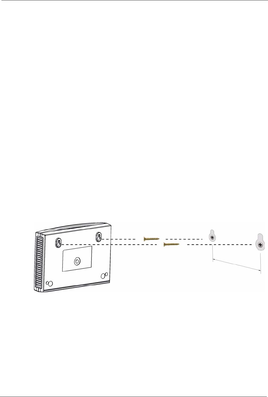
Do the following to hang your ZyXEL Device on a wall.
Note: See the product specifications appendix for the size of screws to use and how
far apart to place them.
1Locate a high position on wall that is free of obstructions. Use a sturdy wall.
2Drill two holes for the screws. Make sure the distance between the centers of the holes
matches what is listed in the product specifications appendix.
Note: Be careful to avoid damaging pipes or cables located inside the wall when
drilling holes for the screws.
3Do not screw the screws all the way into the wall. Leave a small gap of about 0.5 cm
between the heads of the screws and the wall.
4Make sure the screws are snugly fastened to the wall. They need to hold the weight of the
ZyXEL Device with the connection cables.
5Align the holes on the back of the ZyXEL Device with the screws on the wall. Hang the
ZyXEL Device on the screws.
Figure 155 Wall-mounting Example

P-660H/HW-D Series User’s Guide
273 Appendix D Wall-mounting Instructions

P-660H/HW-D Series User’s Guide
Appendix E Setting up Your Computer’s IP Address 274
APPENDIX E
Setting up Your Computer’s IP Address
All computers must have a 10M or 100M Ethernet adapter card and TCP/IP installed.
Windows 95/98/Me/NT/2000/XP, Macintosh OS 7 and later operating systems and all
versions of UNIX/LINUX include the software components you need to install and use TCP/
IP on your computer. Windows 3.1 requires the purchase of a third-party TCP/IP application
package.
TCP/IP should already be installed on computers using Windows NT/2000/XP, Macintosh OS
7 and later operating systems.
After the appropriate TCP/IP components are installed, configure the TCP/IP settings in order
to "communicate" with your network.
If you manually assign IP information instead of using dynamic assignment, make sure that
your computers have IP addresses that place them in the same subnet as the ZyXEL Device’s
LAN port.
Windows 95/98/Me
Click Start, Settings, Control Panel and double-click the Network icon to open the Network
window.
P-660H/HW-D Series User’s Guide
275 Appendix E Setting up Your Computer’s IP Address
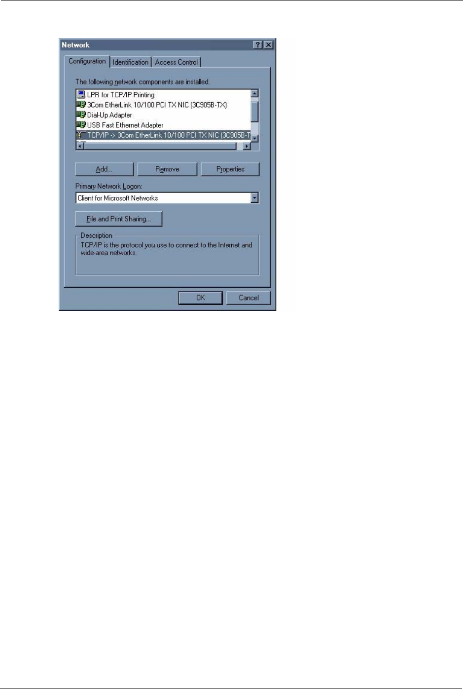
Figure 156 WIndows 95/98/Me: Network: Configuration
Installing Components
The Network window Configuration tab displays a list of installed components. You need a
network adapter, the TCP/IP protocol and Client for Microsoft Networks.
If you need the adapter:
1In the Network window, click Add.
2Select Adapter and then click Add.
3Select the manufacturer and model of your network adapter and then click OK.
If you need TCP/IP:
1In the Network window, click Add.
2Select Protocol and then click Add.
3Select Microsoft from the list of manufacturers.
4Select TCP/IP from the list of network protocols and then click OK.
If you need Client for Microsoft Networks:
1Click Add.
2Select Client and then click Add.
P-660H/HW-D Series User’s Guide
Appendix E Setting up Your Computer’s IP Address 276
3Select Microsoft from the list of manufacturers.
4Select Client for Microsoft Networks from the list of network clients and then click
OK.
5Restart your computer so the changes you made take effect.
Configuring
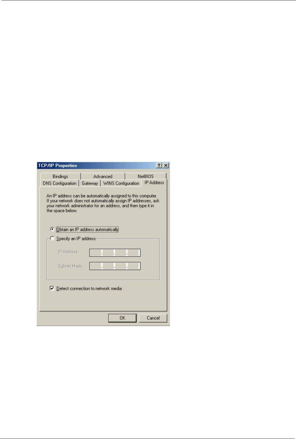
1In the Network window Configuration tab, select your network adapter's TCP/IP entry
and click Properties
2Click the IP Address tab.
• If your IP address is dynamic, select Obtain an IP address
automatically.
• If you have a static IP address, select Specify an IP address and type
your information into the IP Address and Subnet Mask fields.
Figure 157 Windows 95/98/Me: TCP/IP Properties: IP Address
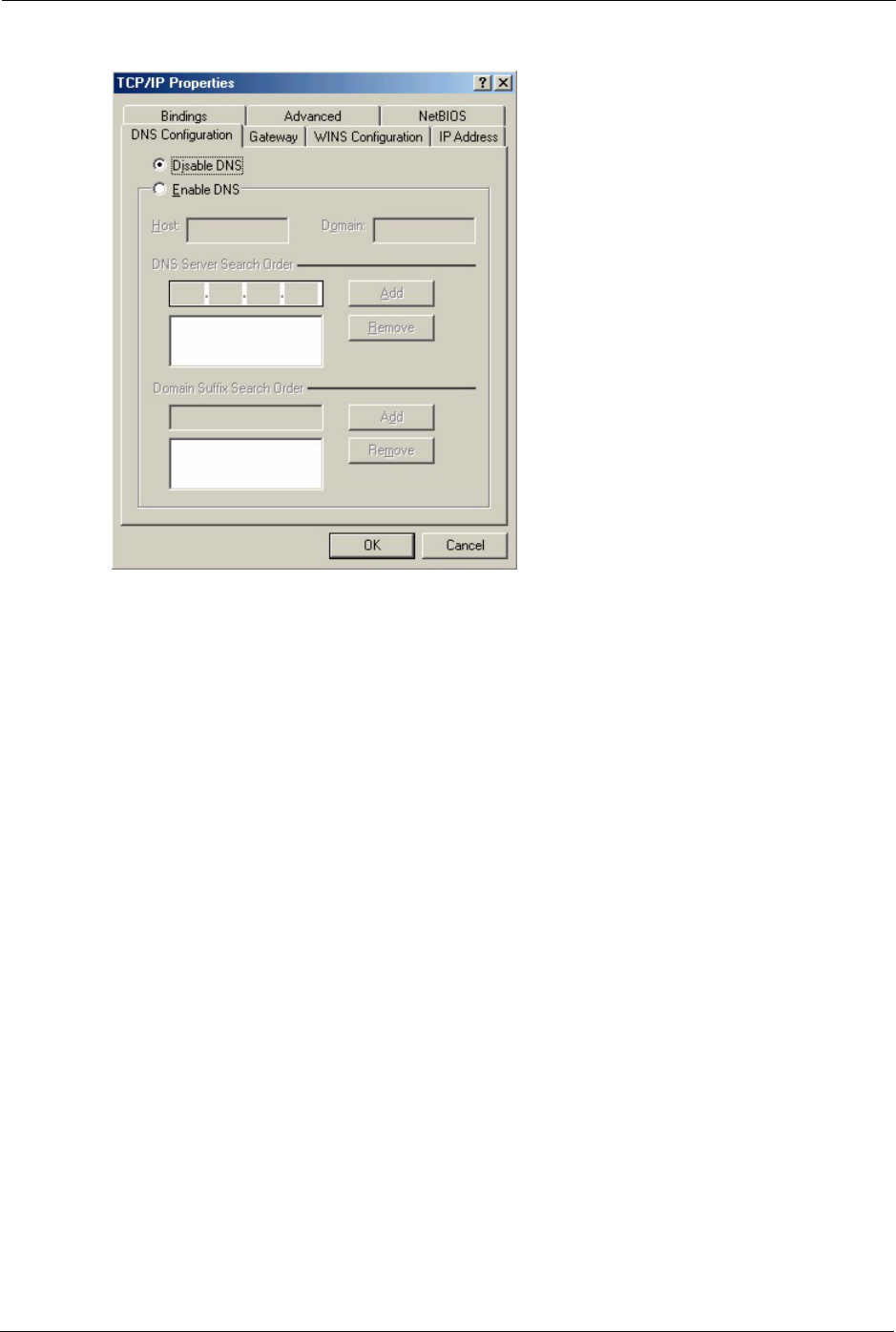
3Click the DNS Configuration tab.
• If you do not know your DNS information, select Disable DNS.
• If you know your DNS information, select Enable DNS and type the
information in the fields below (you may not need to fill them all in).
P-660H/HW-D Series User’s Guide
277 Appendix E Setting up Your Computer’s IP Address
Figure 158 Windows 95/98/Me: TCP/IP Properties: DNS Configuration
4Click the Gateway tab.
• If you do not know your gateway’s IP address, remove previously
installed gateways.
• If you have a gateway IP address, type it in the New gateway field
and click Add.
5Click OK to save and close the TCP/IP Properties window.
6Click OK to close the Network window. Insert the Windows CD if prompted.
7Turn on your ZyXEL Device and restart your computer when prompted.
Verifying Settings
1Click Start and then Run.
2In the Run window, type "winipcfg" and then click OK to open the IP Configuration
window.
3Select your network adapter. You should see your computer's IP address, subnet mask
and default gateway.
Windows 2000/NT/XP
The following example figures use the default Windows XP GUI theme.
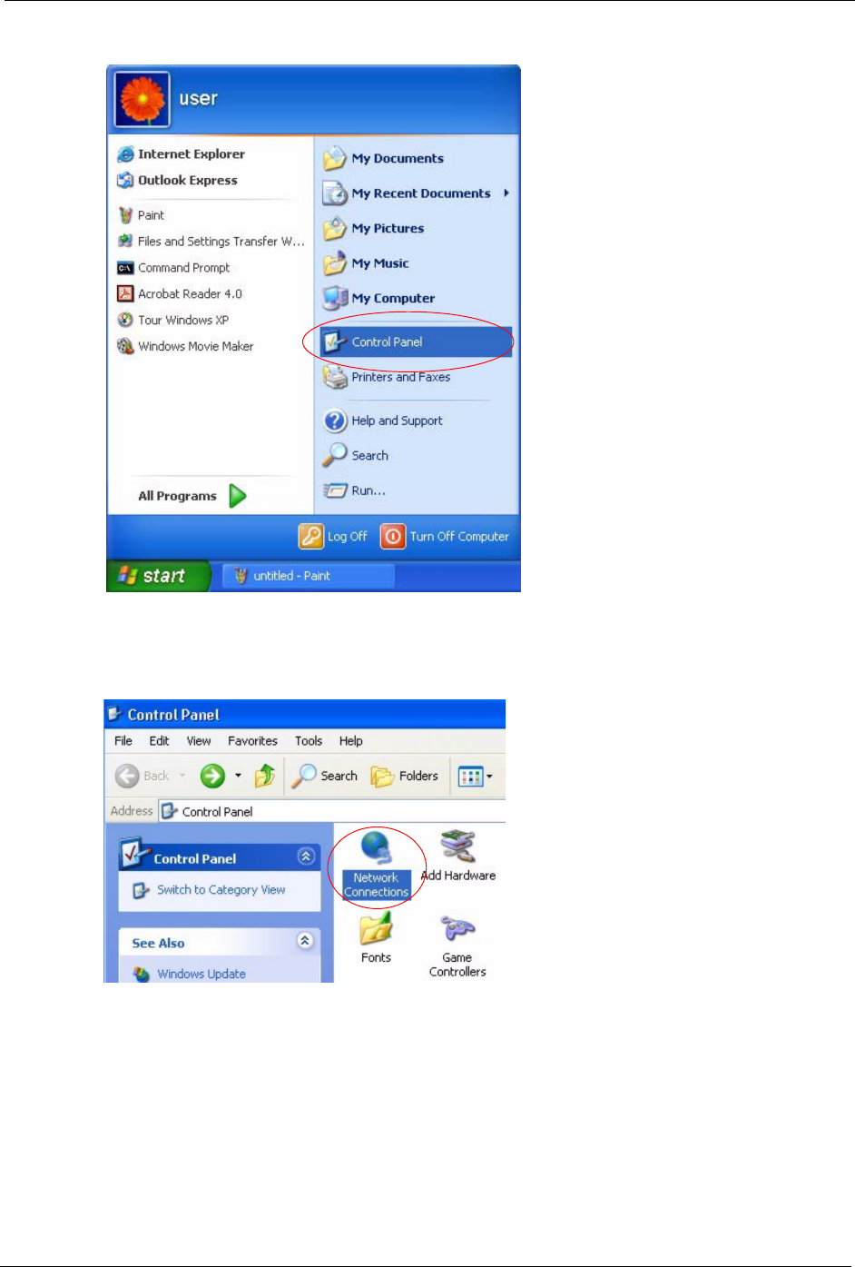
1Click start (Start in Windows 2000/NT), Settings, Control Panel.
P-660H/HW-D Series User’s Guide
Appendix E Setting up Your Computer’s IP Address 278
Figure 159 Windows XP: Start Menu
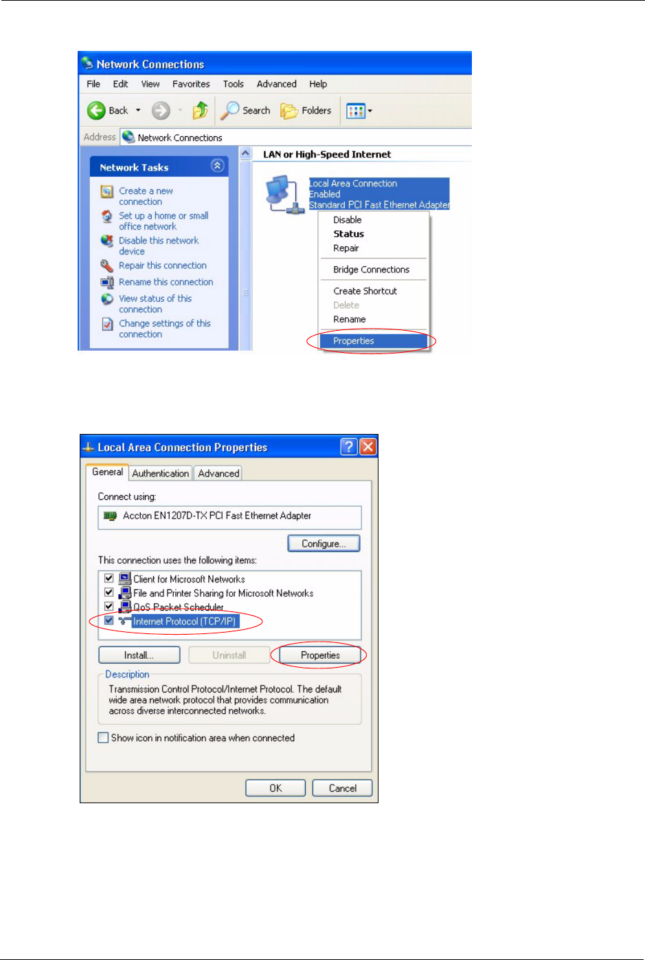
2In the Control Panel, double-click Network Connections (Network and Dial-up
Connections in Windows 2000/NT).
Figure 160 Windows XP: Control Panel
3Right-click Local Area Connection and then click Properties.
P-660H/HW-D Series User’s Guide
279 Appendix E Setting up Your Computer’s IP Address
Figure 161 Windows XP: Control Panel: Network Connections: Properties
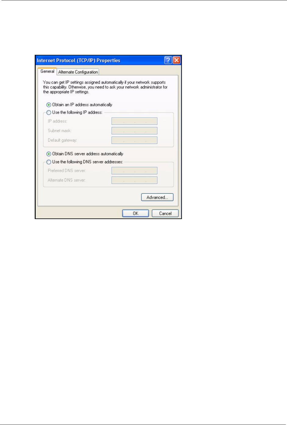
4Select Internet Protocol (TCP/IP) (under the General tab in Win XP) and then click
Properties.
Figure 162 Windows XP: Local Area Connection Properties
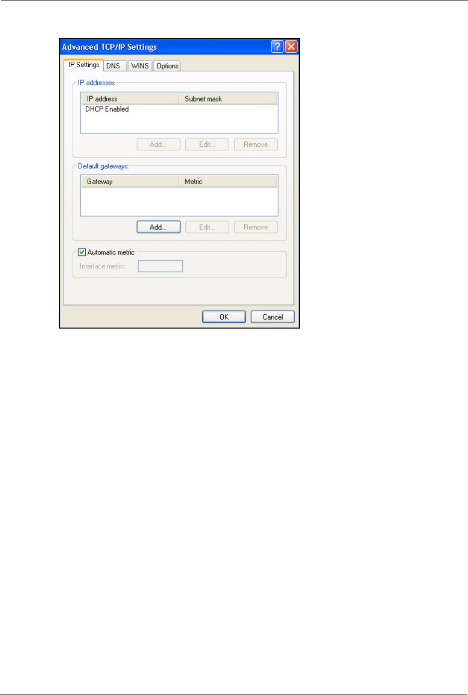
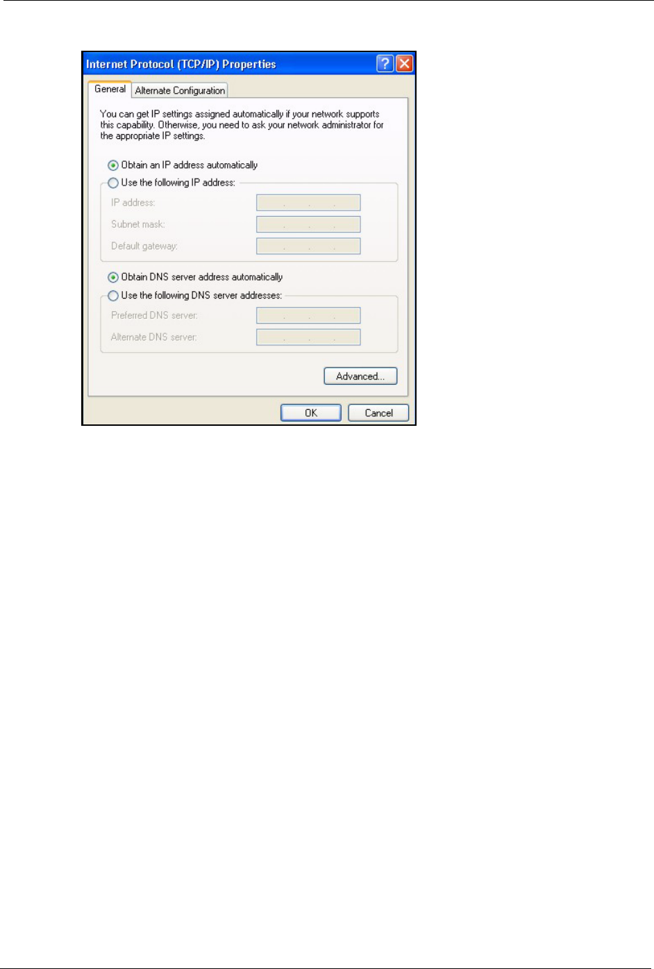
5The Internet Protocol TCP/IP Properties window opens (the General tab in Windows
XP).
• If you have a dynamic IP address click Obtain an IP address
automatically.
P-660H/HW-D Series User’s Guide
Appendix E Setting up Your Computer’s IP Address 280
• If you have a static IP address click Use the following IP Address
and fill in the IP address, Subnet mask, and Default gateway fields.
• Click Advanced.
Figure 163 Windows XP: Internet Protocol (TCP/IP) Properties
6 If you do not know your gateway's IP address, remove any previously installed gateways
in the IP Settings tab and click OK.
Do one or more of the following if you want to configure additional IP addresses:
•In the IP Settings tab, in IP addresses, click Add.
•In TCP/IP Address, type an IP address in IP address and a subnet
mask in Subnet mask, and then click Add.
• Repeat the above two steps for each IP address you want to add.
• Configure additional default gateways in the IP Settings tab by
clicking Add in Default gateways.
•In TCP/IP Gateway Address, type the IP address of the default
gateway in Gateway. To manually configure a default metric (the
number of transmission hops), clear the Automatic metric check box
and type a metric in Metric.
• Click Add.
• Repeat the previous three steps for each default gateway you want to
add.
• Click OK when finished.
P-660H/HW-D Series User’s Guide
281 Appendix E Setting up Your Computer’s IP Address
Figure 164 Windows XP: Advanced TCP/IP Properties
7In the Internet Protocol TCP/IP Properties window (the General tab in Windows XP):
• Click Obtain DNS server address automatically if you do not know
your DNS server IP address(es).
• If you know your DNS server IP address(es), click Use the following
DNS server addresses, and type them in the Preferred DNS server
and Alternate DNS server fields.
If you have previously configured DNS servers, click Advanced and
then the DNS tab to order them.
P-660H/HW-D Series User’s Guide
Appendix E Setting up Your Computer’s IP Address 282
Figure 165 Windows XP: Internet Protocol (TCP/IP) Properties
8Click OK to close the Internet Protocol (TCP/IP) Properties window.
9Click Close (OK in Windows 2000/NT) to close the Local Area Connection Properties
window.
10 Close the Network Connections window (Network and Dial-up Connections in
Windows 2000/NT).
11Turn on your ZyXEL Device and restart your computer (if prompted).
Verifying Settings
1Click Start, All Programs, Accessories and then Command Prompt.
2In the Command Prompt window, type "ipconfig" and then press [ENTER]. You can
also open Network Connections, right-click a network connection, click Status and then
click the Support tab.
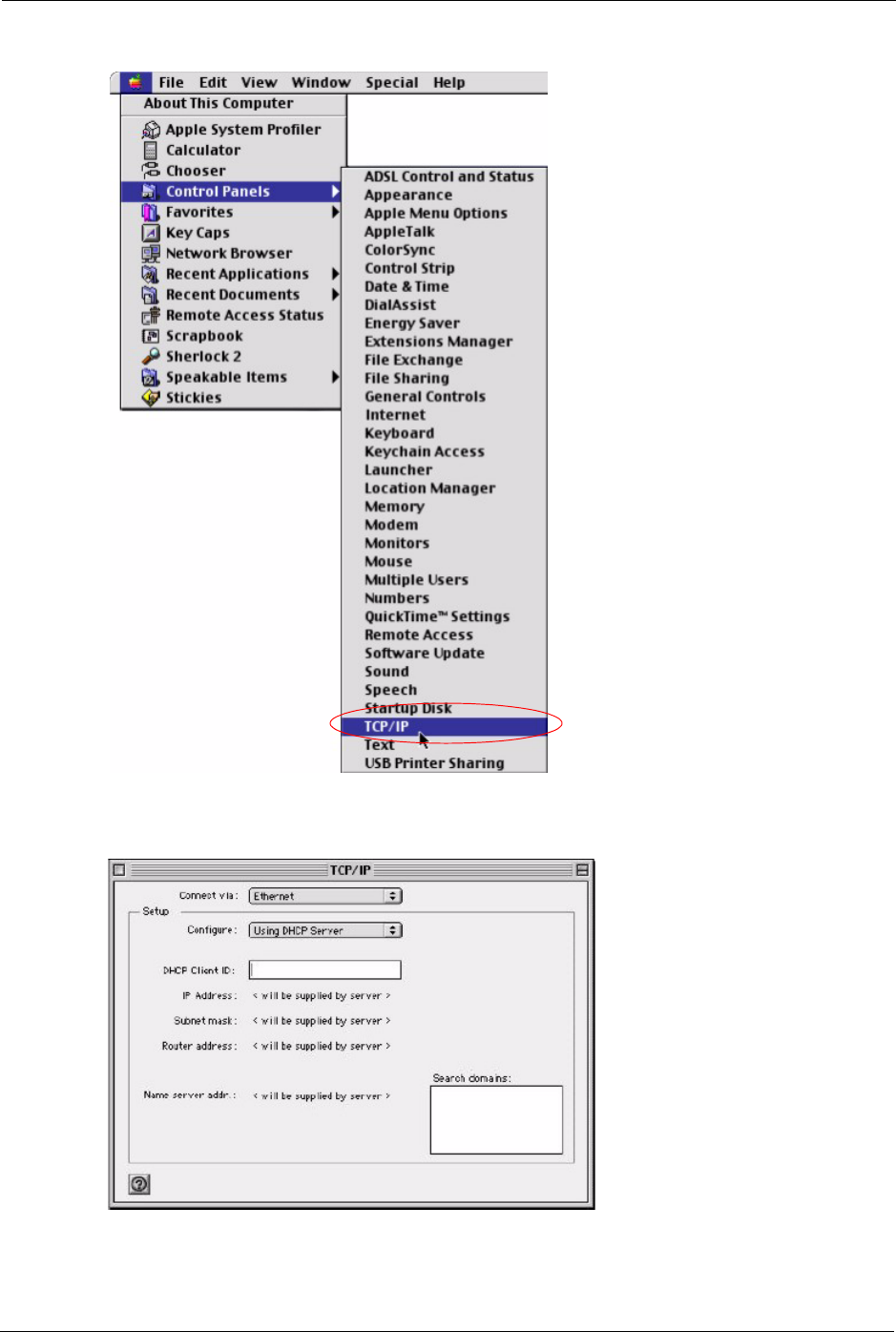
Macintosh OS 8/9
1Click the Apple menu, Control Panel and double-click TCP/IP to open the TCP/IP
Control Panel.
P-660H/HW-D Series User’s Guide
283 Appendix E Setting up Your Computer’s IP Address
Figure 166 Macintosh OS 8/9: Apple Menu
2Select Ethernet built-in from the Connect via list.
Figure 167 Macintosh OS 8/9: TCP/IP
3For dynamically assigned settings, select Using DHCP Server from the Configure: list.
P-660H/HW-D Series User’s Guide
Appendix E Setting up Your Computer’s IP Address 284
4For statically assigned settings, do the following:
•From the Configure box, select Manually.
• Type your IP address in the IP Address box.
• Type your subnet mask in the Subnet mask box.
• Type the IP address of your ZyXEL Device in the Router address
box.
5Close the TCP/IP Control Panel.
6Click Save if prompted, to save changes to your configuration.
7Turn on your ZyXEL Device and restart your computer (if prompted).
Verifying Settings
Check your TCP/IP properties in the TCP/IP Control Panel window.
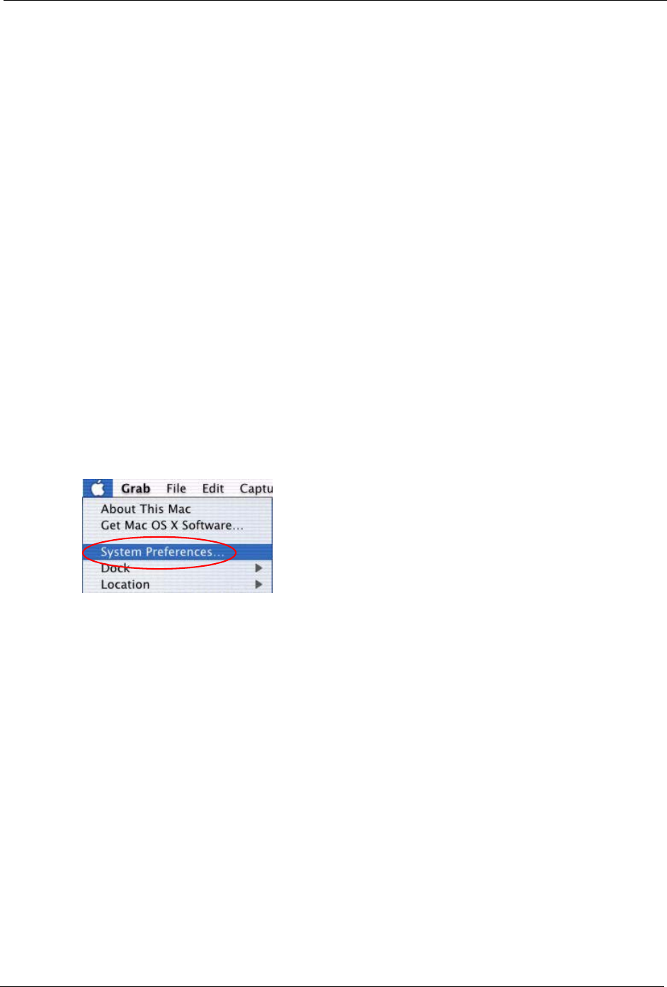
Macintosh OS X
1Click the Apple menu, and click System Preferences to open the System Preferences
window.
Figure 168 Macintosh OS X: Apple Menu
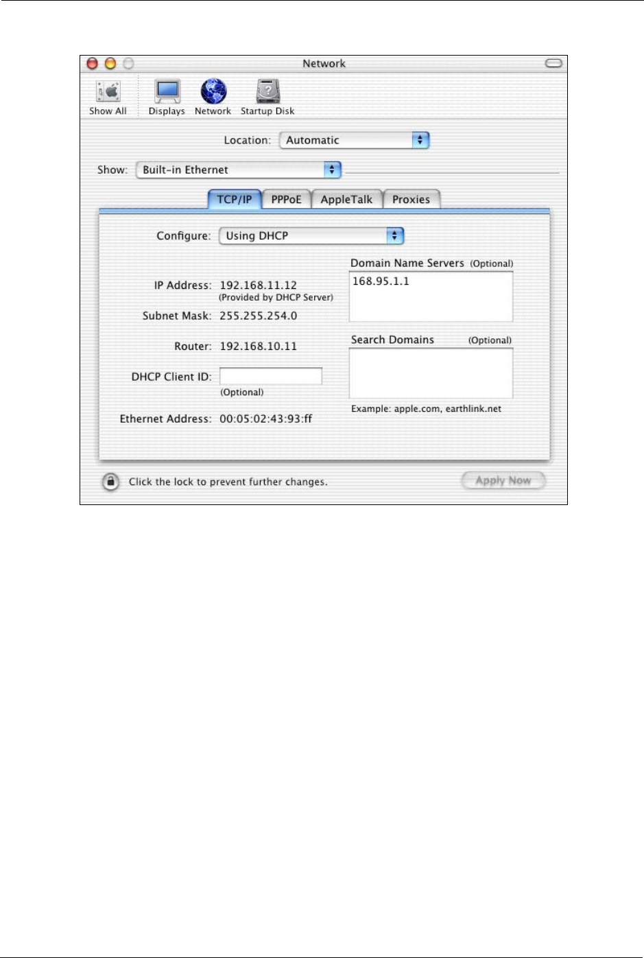
2Click Network in the icon bar.
• Select Automatic from the Location list.
• Select Built-in Ethernet from the Show list.
• Click the TCP/IP tab.
3For dynamically assigned settings, select Using DHCP from the Configure list.
P-660H/HW-D Series User’s Guide
285 Appendix E Setting up Your Computer’s IP Address
Figure 169 Macintosh OS X: Network
4For statically assigned settings, do the following:
•From the Configure box, select Manually.
• Type your IP address in the IP Address box.
• Type your subnet mask in the Subnet mask box.
• Type the IP address of your ZyXEL Device in the Router address
box.
5Click Apply Now and close the window.
6Turn on your ZyXEL Device and restart your computer (if prompted).
Verifying Settings
Check your TCP/IP properties in the Network window.
Linux
This section shows you how to configure your computer’s TCP/IP settings in Red Hat Linux
9.0. Procedure, screens and file location may vary depending on your Linux distribution and
release version.
P-660H/HW-D Series User’s Guide
Appendix E Setting up Your Computer’s IP Address 286
Note: Make sure you are logged in as the root administrator.
Using the K Desktop Environment (KDE)
Follow the steps below to configure your computer IP address using the KDE.
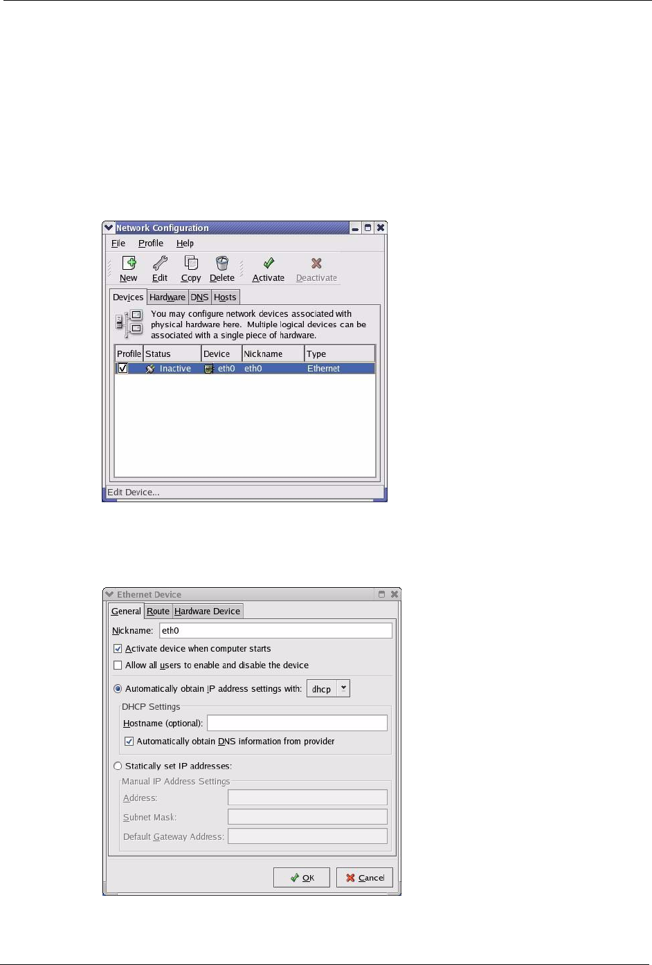
1Click the Red Hat button (located on the bottom left corner), select System Setting and
click Network.
Figure 170 Red Hat 9.0: KDE: Network Configuration: Devices
2Double-click on the profile of the network card you wish to configure. The Ethernet
Device General screen displays as shown.
Figure 171 Red Hat 9.0: KDE: Ethernet Device: General
P-660H/HW-D Series User’s Guide
287 Appendix E Setting up Your Computer’s IP Address
• If you have a dynamic IP address click Automatically obtain IP
address settings with and select dhcp from the drop down list.
• If you have a static IP address click Statically set IP Addresses and
fill in the Address, Subnet mask, and Default Gateway Address
fields.
3Click OK to save the changes and close the Ethernet Device General screen.
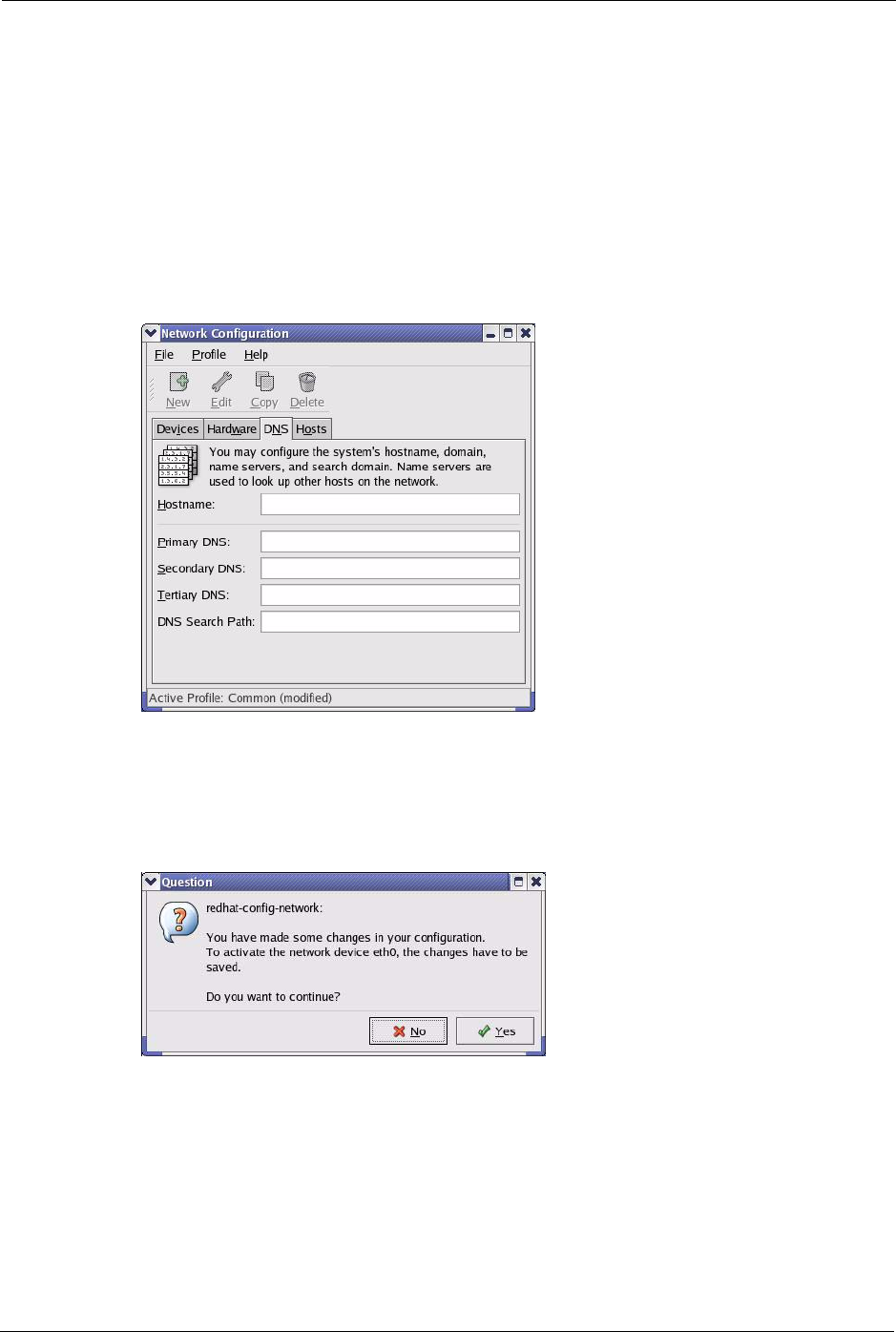
4If you know your DNS server IP address(es), click the DNS tab in the Network
Configuration screen. Enter the DNS server information in the fields provided.
Figure 172 Red Hat 9.0: KDE: Network Configuration: DNS
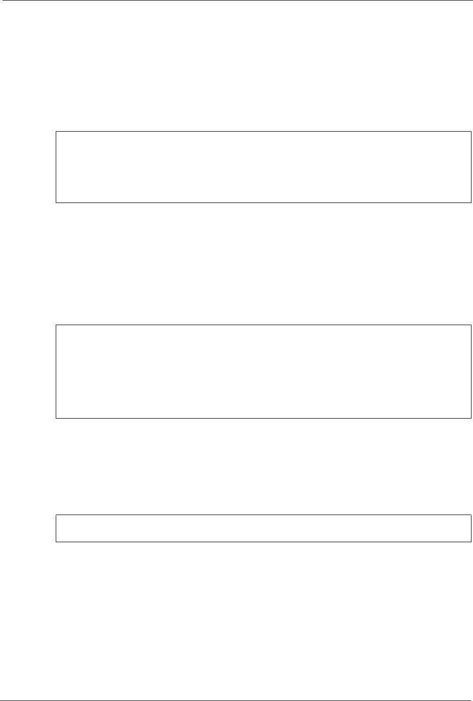
5Click the Devices tab.
6Click the Activate button to apply the changes. The following screen displays. Click Ye s
to save the changes in all screens.
Figure 173 Red Hat 9.0: KDE: Network Configuration: Activate
7After the network card restart process is complete, make sure the Status is Active in the
Network Configuration screen.
Using Configuration Files
Follow the steps below to edit the network configuration files and set your computer IP
address.
P-660H/HW-D Series User’s Guide
Appendix E Setting up Your Computer’s IP Address 288
1Assuming that you have only one network card on the computer, locate the ifconfig-
eth0 configuration file (where eth0 is the name of the Ethernet card). Open the
configuration file with any plain text editor.
• If you have a dynamic IP address, enter dhcp in the BOOTPROTO=
field. The following figure shows an example.
Figure 174 Red Hat 9.0: Dynamic IP Address Setting in ifconfig-eth0
• If you have a static IP address, enter static in the BOOTPROTO=
field. Type IPADDR= followed by the IP address (in dotted decimal
notation) and type NETMASK= followed by the subnet mask. The
following example shows an example where the static IP address is
192.168.1.10 and the subnet mask is 255.255.255.0.
Figure 175 Red Hat 9.0: Static IP Address Setting in ifconfig-eth0
2If you know your DNS server IP address(es), enter the DNS server information in the
resolv.conf file in the /etc directory. The following figure shows an example where
two DNS server IP addresses are specified.
Figure 176 Red Hat 9.0: DNS Settings in resolv.conf
3After you edit and save the configuration files, you must restart the network card. Enter
./network restart in the /etc/rc.d/init.d directory. The following figure
shows an example.
DEVICE=eth0
ONBOOT=yes
BOOTPROTO=dhcp
USERCTL=no
PEERDNS=yes
TYPE=Ethernet
DEVICE=eth0
ONBOOT=yes
BOOTPROTO=static
IPADDR=192.168.1.10
NETMASK=255.255.255.0
USERCTL=no
PEERDNS=yes
TYPE=Ethernet
nameserver 172.23.5.1
nameserver 172.23.5.2

P-660H/HW-D Series User’s Guide
289 Appendix E Setting up Your Computer’s IP Address
Figure 177 Red Hat 9.0: Restart Ethernet Card
21.4.1 Verifying Settings
Enter ifconfig in a terminal screen to check your TCP/IP properties.
Figure 178 Red Hat 9.0: Checking TCP/IP Properties
[root@localhost init.d]# network restart
Shutting down interface eth0: [OK]
Shutting down loopback interface: [OK]
Setting network parameters: [OK]
Bringing up loopback interface: [OK]
Bringing up interface eth0: [OK]
[root@localhost]# ifconfig
eth0 Link encap:Ethernet HWaddr 00:50:BA:72:5B:44
inet addr:172.23.19.129 Bcast:172.23.19.255 Mask:255.255.255.0
UP BROADCAST RUNNING MULTICAST MTU:1500 Metric:1
RX packets:717 errors:0 dropped:0 overruns:0 frame:0
TX packets:13 errors:0 dropped:0 overruns:0 carrier:0
collisions:0 txqueuelen:100
RX bytes:730412 (713.2 Kb) TX bytes:1570 (1.5 Kb)
Interrupt:10 Base address:0x1000
[root@localhost]#

P-660H/HW-D Series User’s Guide
Appendix F IP Addresses and Subnetting 290
APPENDIX F
IP Addresses and Subnetting
This appendix introduces IP addresses, IP address classes and subnet masks. You use subnet
masks to subdivide a network into smaller logical networks.
Introduction to IP Addresses
An IP address has two parts: the network number and the host ID. Routers use the network
number to send packets to the correct network, while the host ID identifies a single device on
the network.
An IP address is made up of four octets, written in dotted decimal notation, for example,
192.168.1.1. (An octet is an 8-digit binary number. Therefore, each octet has a possible range
of 00000000 to 11111111 in binary, or 0 to 255 in decimal.)
There are several classes of IP addresses. The first network number (192 in the above
example) defines the class of IP address. These are defined as follows:
• Class A: 0 to 127
• Class B: 128 to 191
• Class C: 192 to 223
• Class D: 224 to 239
• Class E: 240 to 255
IP Address Classes and Hosts
The class of an IP address determines the number of hosts you can have on your network.
• In a class A address the first octet is the network number, and the remaining three octets
are the host ID.
• In a class B address the first two octets make up the network number, and the two
remaining octets make up the host ID.
• In a class C address the first three octets make up the network number, and the last octet
is the host ID.
P-660H/HW-D Series User’s Guide
291 Appendix F IP Addresses and Subnetting
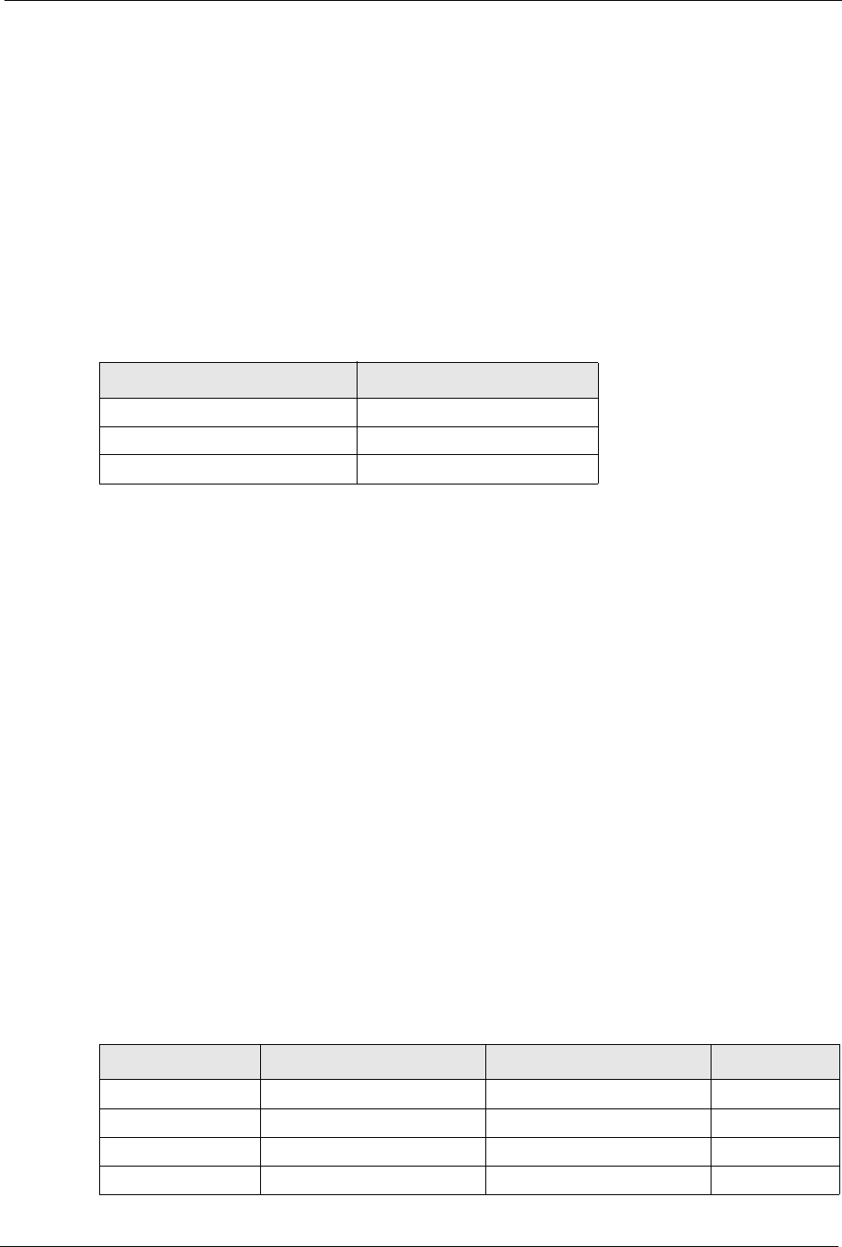
The following table shows the network number and host ID arrangement for classes A, B and
C.
An IP address with host IDs of all zeros is the IP address of the network (192.168.1.0 for
example). An IP address with host IDs of all ones is the broadcast address for that network
(192.168.1.255 for example). Therefore, to determine the total number of hosts allowed in a
network, deduct two as shown next:
• A class C address (1 host octet: 8 host bits) can have 28 – 2, or 254 hosts.
• A class B address (2 host octets: 16 host bits) can have 216 – 2, or 65534 hosts.
A class A address (3 host octets: 24 host bits) can have 224 – 2 hosts, or approximately 16
million hosts.
IP Address Classes and Network ID
The value of the first octet of an IP address determines the class of an address.
• Class A addresses have a 0 in the leftmost bit.
• Class B addresses have a 1 in the leftmost bit and a 0 in the next leftmost bit.
• Class C addresses start with 1 1 0 in the first three leftmost bits.
• Class D addresses begin with 1 1 1 0. Class D addresses are used for multicasting, which
is used to send information to groups of computers.
• There is also a class E. It is reserved for future use.
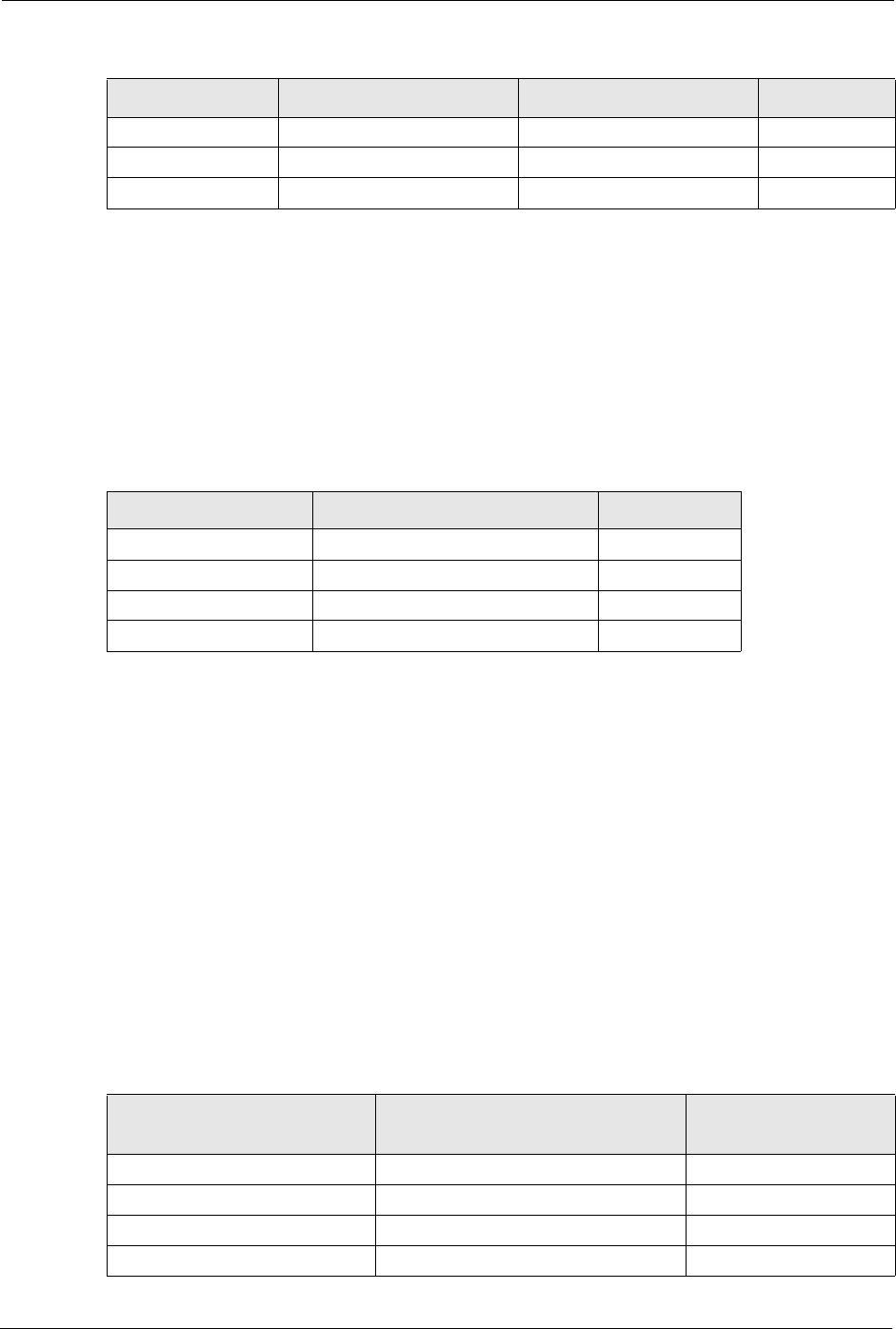
The following table shows the allowed ranges for the first octet of each class. This range
determines the number of subnets you can have in a network.
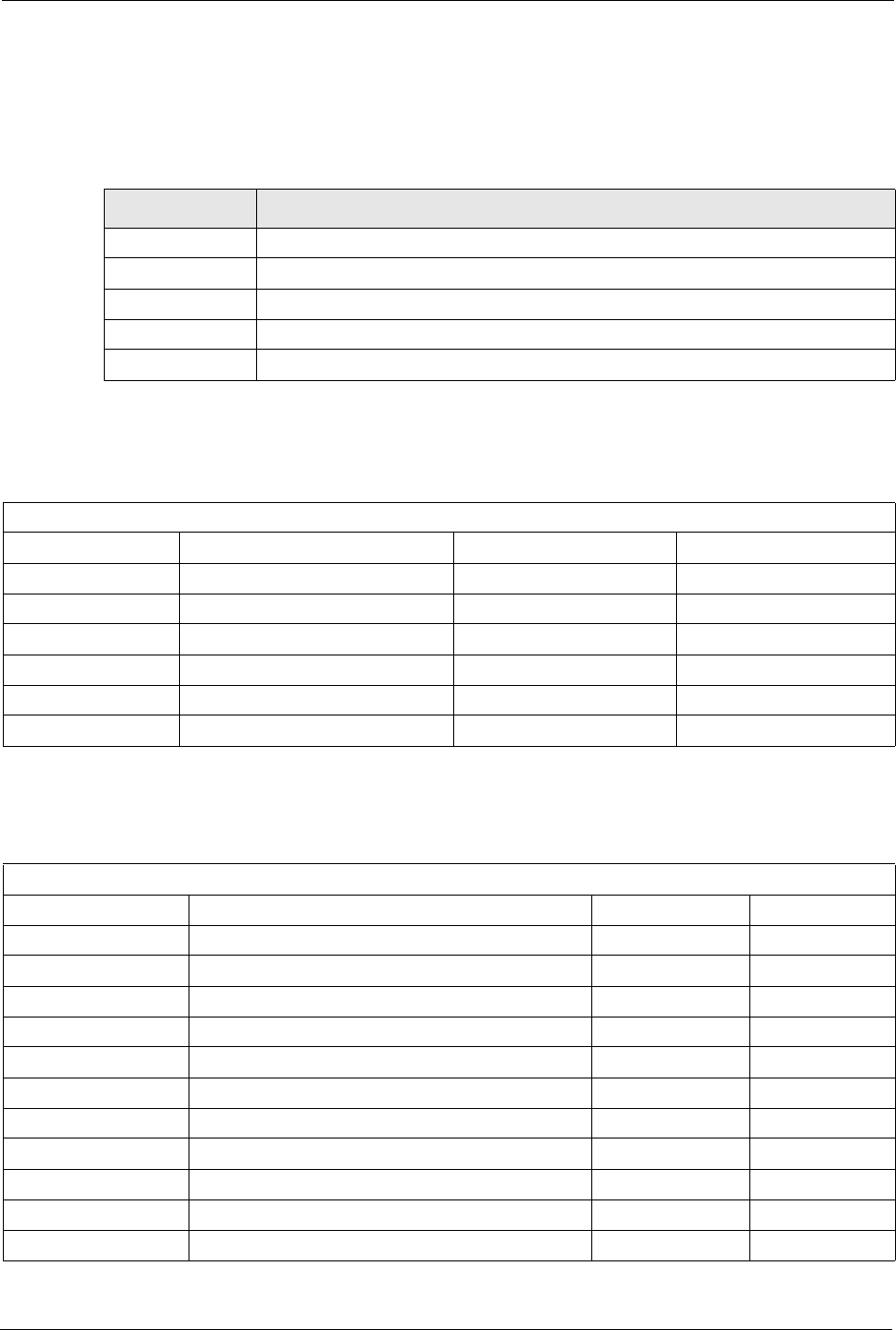
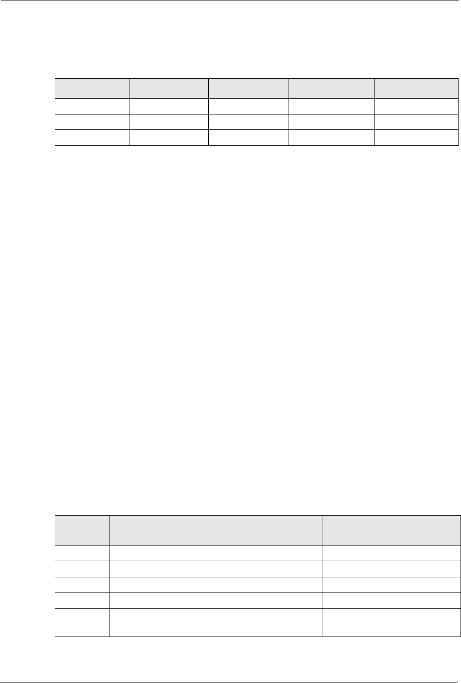
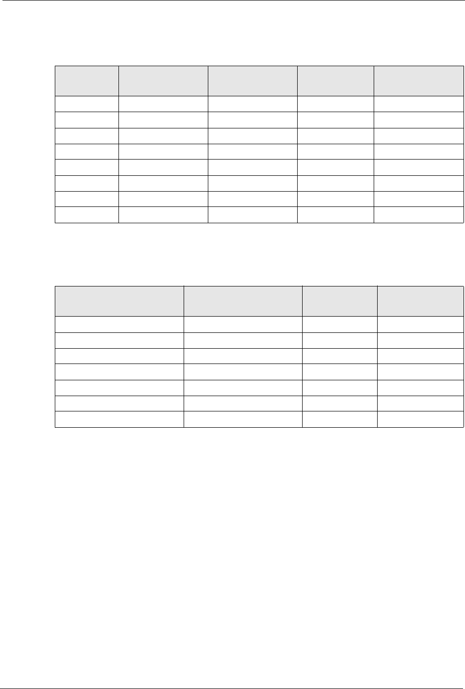
Table 114 Classes of IP Addresses
IP ADDRESS OCTET 1 OCTET 2 OCTET 3 OCTET 4
Class A Network number Host ID Host ID Host ID
Class B Network number Network number Host ID Host ID
Class C Network number Network number Network number Host ID
Table 115 Allowed IP Address Range By Class
CLASS ALLOWED RANGE OF FIRST OCTET (BINARY) ALLOWED RANGE OF FIRST
OCTET (DECIMAL)
Class A 00000000 to 01111111 0 to 127
Class B 10000000 to 10111111 128 to 191
Class C 11000000 to 11011111 192 to 223
Class D 11100000 to 11101111 224 to 239
Class E
(reserved)
11110000 to 11111111 240 to 255
P-660H/HW-D Series User’s Guide
Appendix F IP Addresses and Subnetting 292
Subnet Masks
A subnet mask is used to determine which bits are part of the network number, and which bits
are part of the host ID (using a logical AND operation).
A subnet mask has 32 bits. If a bit in the subnet mask is a “1” then the corresponding bit in the
IP address is part of the network number. If a bit in the subnet mask is “0” then the
corresponding bit in the IP address is part of the host ID.
Subnet masks are expressed in dotted decimal notation just like IP addresses. The “natural”
masks for class A, B and C IP addresses are as follows.
Subnetting
With subnetting, the class arrangement of an IP address is ignored. For example, a class C
address no longer has to have 24 bits of network number and 8 bits of host ID. With
subnetting, some of the host ID bits are converted into network number bits.
By convention, subnet masks always consist of a continuous sequence of ones beginning from
the leftmost bit of the mask, followed by a continuous sequence of zeros, for a total number of
32 bits.
Since the mask is always a continuous number of ones beginning from the left, followed by a
continuous number of zeros for the remainder of the 32 bit mask, you can simply specify the
number of ones instead of writing the value of each octet. This is usually specified by writing
a “/” followed by the number of bits in the mask after the address.
For example, 192.1.1.0 /25 is equivalent to saying 192.1.1.0 with mask 255.255.255.128.
The following table shows all possible subnet masks for a class “C” address using both
notations.
Table 116 “Natural” Masks
CLASS NATURAL MASK
A255.0.0.0
B255.255.0.0
C255.255.255.0
Table 117 Alternative Subnet Mask Notation
SUBNET MASK SUBNET MASK “1” BITS LAST OCTET BIT VALUE DECIMAL
255.255.255.0 /24 0000 0000 0
255.255.255.128 /25 1000 0000 128
255.255.255.192 /26 1100 0000 192
255.255.255.224 /27 1110 0000 224
P-660H/HW-D Series User’s Guide
293 Appendix F IP Addresses and Subnetting
The first mask shown is the class “C” natural mask. Normally if no mask is specified it is
understood that the natural mask is being used.
Example: Two Subnets
As an example, you have a class “C” address 192.168.1.0 with subnet mask of 255.255.255.0.
The first three octets of the address make up the network number (class “C”).
To make two networks, divide the network 192.168.1.0 into two separate subnets by
converting one of the host ID bits of the IP address to a network number bit. The “borrowed”
host ID bit can be either “0” or “1” thus giving two subnets; 192.168.1.0 with mask
255.255.255.128 and 192.168.1.128 with mask 255.255.255.128.
Note: In the following charts, shaded/bolded last octet bit values indicate host ID bits
“borrowed” to make network ID bits. The number of “borrowed” host ID bits
determines the number of subnets you can have. The remaining number of
host ID bits (after “borrowing”) determines the number of hosts you can have
on each subnet.
255.255.255.240 /28 1111 0000 240
255.255.255.248 /29 1111 1000 248
255.255.255.252 /30 1111 1100 252
Table 117 Alternative Subnet Mask Notation (continued)
SUBNET MASK SUBNET MASK “1” BITS LAST OCTET BIT VALUE DECIMAL
Table 118 Two Subnets Example
IP/SUBNET MASK NETWORK NUMBER HOST ID
IP Address 192.168.1. 0
IP Address (Binary) 11000000.10101000.00000001. 00000000
Subnet Mask 255.255.255. 0
Subnet Mask (Binary) 11111111.11111111.11111111. 00000000
Table 119 Subnet 1
IP/SUBNET MASK NETWORK NUMBER LAST OCTET BIT
VALUE
IP Address 192.168.1. 0
IP Address (Binary) 11000000.10101000.00000001. 00000000
Subnet Mask 255.255.255. 128
Subnet Mask (Binary) 11111111.11111111.11111111. 10000000
P-660H/HW-D Series User’s Guide
Appendix F IP Addresses and Subnetting 294
Host IDs of all zeros represent the subnet itself and host IDs of all ones are the broadcast
address for that subnet, so the actual number of hosts available on each subnet in the example
above is 27 – 2 or 126 hosts for each subnet.
192.168.1.0 with mask 255.255.255.128 is the subnet itself, and 192.168.1.127 with mask
255.255.255.128 is the directed broadcast address for the first subnet. Therefore, the lowest IP
address that can be assigned to an actual host for the first subnet is 192.168.1.1 and the highest
is 192.168.1.126. Similarly the host ID range for the second subnet is 192.168.1.129 to
192.168.1.254.
Example: Four Subnets
The above example illustrated using a 25-bit subnet mask to divide a class “C” address space
into two subnets. Similarly to divide a class “C” address into four subnets, you need to
“borrow” two host ID bits to give four possible combinations (00, 01, 10 and 11). The subnet
mask is 26 bits (11111111.11111111.11111111.11000000) or 255.255.255.192. Each subnet
contains 6 host ID bits, giving 26-2 or 62 hosts for each subnet (all zeroes is the subnet itself,
all ones is the broadcast address on the subnet).
Subnet Address: 192.168.1.0 Lowest Host ID: 192.168.1.1
Broadcast Address:
192.168.1.127
Highest Host ID: 192.168.1.126
Table 120 Subnet 2
IP/SUBNET MASK NETWORK NUMBER LAST OCTET BIT VALUE
IP Address 192.168.1. 128
IP Address (Binary) 11000000.10101000.00000001. 10000000
Subnet Mask 255.255.255. 128
Subnet Mask (Binary) 11111111.11111111.11111111. 10000000
Subnet Address:
192.168.1.128
Lowest Host ID: 192.168.1.129
Broadcast Address:
192.168.1.255
Highest Host ID: 192.168.1.254
Table 119 Subnet 1 (continued)
IP/SUBNET MASK NETWORK NUMBER LAST OCTET BIT
VALUE
Table 121 Subnet 1
IP/SUBNET MASK NETWORK NUMBER LAST OCTET BIT
VALUE
IP Address 192.168.1. 0
IP Address (Binary) 11000000.10101000.00000001. 00000000
Subnet Mask (Binary) 11111111.11111111.11111111. 11000000
P-660H/HW-D Series User’s Guide
295 Appendix F IP Addresses and Subnetting
Example Eight Subnets
Similarly use a 27-bit mask to create eight subnets (000, 001, 010, 011, 100, 101, 110 and
111).
Subnet Address: 192.168.1.0 Lowest Host ID: 192.168.1.1
Broadcast Address:
192.168.1.63
Highest Host ID: 192.168.1.62
Table 122 Subnet 2
IP/SUBNET MASK NETWORK NUMBER LAST OCTET BIT
VALUE
IP Address 192.168.1. 64
IP Address (Binary) 11000000.10101000.00000001. 01000000
Subnet Mask (Binary) 11111111.11111111.11111111. 11000000
Subnet Address: 192.168.1.64 Lowest Host ID: 192.168.1.65
Broadcast Address: 192.168.1.127 Highest Host ID: 192.168.1.126
Table 123 Subnet 3
IP/SUBNET MASK NETWORK NUMBER LAST OCTET BIT
VALUE
IP Address 192.168.1. 128
IP Address (Binary) 11000000.10101000.00000001. 10000000
Subnet Mask (Binary) 11111111.11111111.11111111. 11000000
Subnet Address:
192.168.1.128
Lowest Host ID: 192.168.1.129
Broadcast Address:
192.168.1.191
Highest Host ID: 192.168.1.190
Table 124 Subnet 4
IP/SUBNET MASK NETWORK NUMBER LAST OCTET BIT VALUE
IP Address 192.168.1. 192
IP Address (Binary) 11000000.10101000.00000001. 11000000
Subnet Mask (Binary) 11111111.11111111.11111111. 11000000
Subnet Address:
192.168.1.192
Lowest Host ID: 192.168.1.193
Broadcast Address:
192.168.1.255
Highest Host ID: 192.168.1.254
Table 121 Subnet 1 (continued)
IP/SUBNET MASK NETWORK NUMBER LAST OCTET BIT
VALUE
P-660H/HW-D Series User’s Guide
Appendix F IP Addresses and Subnetting 296
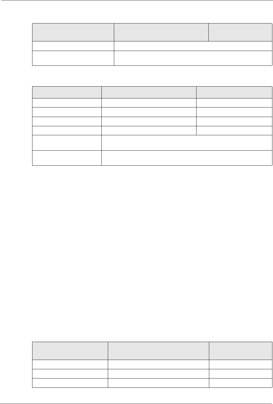
The following table shows class C IP address last octet values for each subnet.
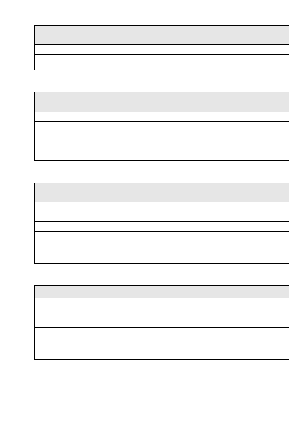
The following table is a summary for class “C” subnet planning.
Subnetting With Class A and Class B Networks.
For class “A” and class “B” addresses the subnet mask also determines which bits are part of
the network number and which are part of the host ID.
A class “B” address has two host ID octets available for subnetting and a class “A” address has
three host ID octets (see Table 114 on page 291) available for subnetting.
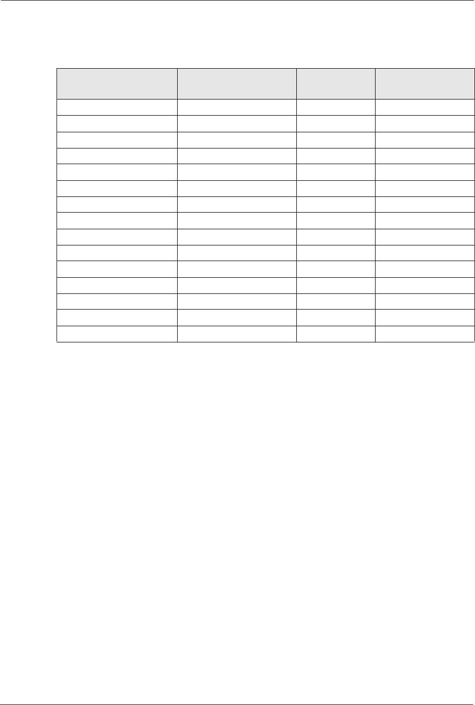
Table 125 Eight Subnets
SUBNET SUBNET ADDRESS FIRST ADDRESS LAST ADDRESS BROADCAST
ADDRESS
1 0 1 30 31
232 33 62 63
364 65 94 95
496 97 126 127
5128 129 158 159
6160 161 190 191
7192 193 222 223
8224 225 254 255
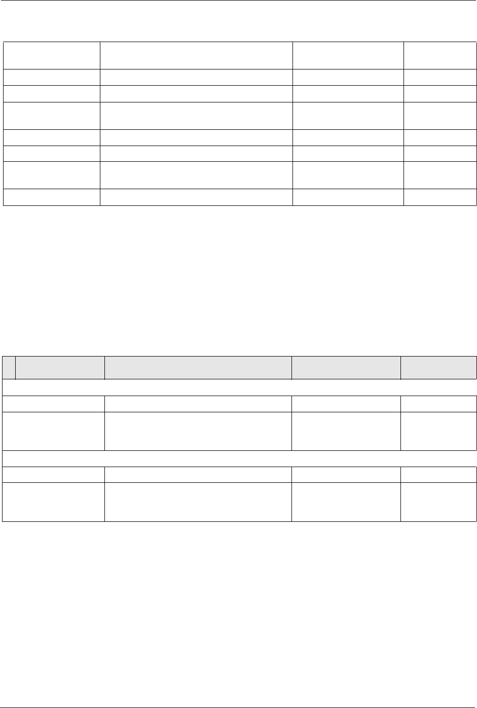
Table 126 Class C Subnet Planning
NO. “BORROWED” HOST
BITS SUBNET MASK NO. SUBNETS NO. HOSTS PER
SUBNET
1255.255.255.128 (/25) 2126
2255.255.255.192 (/26) 462
3255.255.255.224 (/27) 830
4255.255.255.240 (/28) 16 14
5255.255.255.248 (/29) 32 6
6255.255.255.252 (/30) 64 2
7255.255.255.254 (/31) 128 1
P-660H/HW-D Series User’s Guide
297 Appendix F IP Addresses and Subnetting
The following table is a summary for class “B” subnet planning.
Table 127 Class B Subnet Planning
NO. “BORROWED” HOST
BITS SUBNET MASK NO. SUBNETS NO. HOSTS PER
SUBNET
1255.255.128.0 (/17) 232766
2255.255.192.0 (/18) 416382
3255.255.224.0 (/19) 88190
4255.255.240.0 (/20) 16 4094
5255.255.248.0 (/21) 32 2046
6255.255.252.0 (/22) 64 1022
7255.255.254.0 (/23) 128 510
8255.255.255.0 (/24) 256 254
9255.255.255.128 (/25) 512 126
10 255.255.255.192 (/26) 1024 62
11 255.255.255.224 (/27) 2048 30
12 255.255.255.240 (/28) 4096 14
13 255.255.255.248 (/29) 8192 6
14 255.255.255.252 (/30) 16384 2
15 255.255.255.254 (/31) 32768 1

P-660H/HW-D Series User’s Guide
Appendix G Command Interpreter 298
APPENDIX G
Command Interpreter
The following describes how to use the command interpreter. You can telnet to access the CLI
(Command Line Interface) on the ZyXEL Device. See the included disk or zyxel.com for
more detailed information on these commands.
Note: Use of undocumented commands or misconfiguration can damage the unit and
possibly render it unusable.
Accessing the CLI
Use the following steps to telnet into your ZyXEL Device.
1Connect your computer to the ETHERNET port on the ZyXEL Device.
2Make sure your computer IP address and the ZyXEL Device IP address are on the same
subnet. In Windows, click Start (usually in the bottom left corner), Run and then type
telnet 192.168.1.1 (the default ZyXEL Device IP address) and click OK.
3A login screen displays. Enter the default admin password "1234".
Command Syntax
• The command keywords are in courier new font.
• Enter the command keywords exactly as shown, do not abbreviate.
• The required fields in a command are enclosed in angle brackets <>.
• The optional fields in a command are enclosed in square brackets [].
•The |symbol means or.
For example,
sys filter netbios config <type> <on|off>
means that you must specify the type of netbios filter and whether to turn it on or off.
Command Usage
A list of valid commands can be found by typing help or? at the command prompt. Always
type the full command. Type exit to log out of the CLI when finished.

P-660H/HW-D Series User’s Guide
299 Appendix G Command Interpreter

P-660H/HW-D Series User’s Guide
Appendix H Firewall Commands 300
APPENDIX H
Firewall Commands
The following describes the firewall commands.
Table 128 Firewall Commands
FUNCTION COMMAND DESCRIPTION
Firewall SetUp
config edit firewall active
<yes | no>
This command turns the firewall on or off.
config retrieve firewall This command returns the previously saved
firewall settings.
config save firewall This command saves the current firewall
settings.
Display
config display firewall This command shows the of all the firewall
settings including e-mail, attack, and the sets/
rules.
config display firewall set
<set #>
This command shows the current
configuration of a set; including timeout
values, name, default-permit, and etc.If you
don’t put use a number (#) after “set”,
information about all of the sets/rules appears.
config display firewall set
<set #> rule <rule #>
This command shows the current entries of a
rule in a firewall rule set.
config display firewall attack This command shows all of the attack
response settings.
config display firewall e-mail This command shows all of the e-mail
settings.
config display firewall? This command shows all of the available
firewall sub commands.
Edit

P-660H/HW-D Series User’s Guide
301 Appendix H Firewall Commands
E-mail config edit firewall e-mail
mail-server <ip address of
mail server>
This command sets the IP address to which
the e-mail messages are sent.
config edit firewall e-mail
return-addr <e-mail address>
This command sets the source e-mail address
of the firewall e-mails.
config edit firewall e-mail
email-to <e-mail address>
This command sets the e-mail address to
which the firewall e-mails are sent.
config edit firewall e-mail
policy <full | hourly | daily |
weekly>
This command sets how frequently the firewall
log is sent via e-mail.
config edit firewall e-mail
day <sunday | monday | tuesday
| wednesday | thursday | friday
| saturday>
This command sets the day on which the
current firewall log is sent through e-mail if the
ZyXEL Device is set to send it on a weekly
basis.
config edit firewall e-mail
hour <0-23>
This command sets the hour when the firewall
log is sent through e- mail if the ZyXEL Device
is set to send it on an hourly, daily or weekly
basis.
config edit firewall e-mail
minute <0-59>
This command sets the minute of the hour for
the firewall log to be sent via e- mail if the
ZyXEL Device is set to send it on a hourly,
daily or weekly basis.
Attack config edit firewall attack
send-alert <yes | no>
This command enables or disables the
immediate sending of DOS attack notification
e-mail messages.
config edit firewall attack
block <yes | no>
Set this command to yes to block new traffic
after the tcp-max-incomplete threshold is
exceeded. Set it to no to delete the oldest half-
open session when traffic exceeds the tcp-
max-incomplete threshold.
config edit firewall attack
block-minute <0-255>
This command sets the number of minutes for
new sessions to be blocked when the tcp-
max-incomplete threshold is reached. This
command is only valid when block is set to
yes.
Table 128 Firewall Commands (continued)
FUNCTION COMMAND DESCRIPTION

P-660H/HW-D Series User’s Guide
Appendix H Firewall Commands 302
config edit firewall attack
minute-high <0-255>
This command sets the threshold rate of new
half-open sessions per minute where the
ZyXEL Device starts deleting old half-opened
sessions until it gets them down to the minute-
low threshold.
config edit firewall attack
minute-low <0-255>
This command sets the threshold of half-open
sessions where the ZyXEL Device stops
deleting half-opened sessions.
config edit firewall attack
max-incomplete-high <0-255>
This command sets the threshold of half-open
sessions where the ZyXEL Device starts
deleting old half-opened sessions until it gets
them down to the max incomplete low.
config edit firewall attack
max-incomplete-low <0-255>
This command sets the threshold where the
ZyXEL Device stops deleting half-opened
sessions.
config edit firewall attack
tcp-max-incomplete <0-255>
This command sets the threshold of half-open
TCP sessions with the same destination
where the ZyXEL Device starts dropping half-
open sessions to that destination.
Sets config edit firewall set <set
#> name <desired name>
This command sets a name to identify a
specified set.
Config edit firewall set <set
#> default-permit <forward |
block>
This command sets whether a packet is
dropped or allowed through, when it does not
meet a rule within the set.
Config edit firewall set <set
#> icmp-timeout <seconds>
This command sets the time period to allow an
ICMP session to wait for the ICMP response.
Config edit firewall set <set
#> udp-idle-timeout <seconds>
This command sets how long a UDP
connection is allowed to remain inactive
before the ZyXEL Device considers the
connection closed.
Config edit firewall set <set
#> connection-timeout
<seconds>
This command sets how long ZyXEL Device
waits for a TCP session to be established
before dropping the session.
Config edit firewall set <set
#> fin-wait-timeout <seconds>
This command sets how long the ZyXEL
Device leaves a TCP session open after the
firewall detects a FIN-exchange (indicating the
end of the TCP session).
Table 128 Firewall Commands (continued)
FUNCTION COMMAND DESCRIPTION

P-660H/HW-D Series User’s Guide
303 Appendix H Firewall Commands
Config edit firewall set <set
#> tcp-idle-timeout <seconds>
This command sets how long ZyXEL Device
lets an inactive TCP connection remain open
before considering it closed.
Config edit firewall set <set
#> log <yes | no>
This command sets whether or not the ZyXEL
Device creates logs for packets that match the
firewall’s default rule set.
Rules Config edit firewall set <set
#> rule <rule #> permit
<forward | block>
This command sets whether packets that
match this rule are dropped or allowed
through.
Config edit firewall set <set
#> rule <rule #> active <yes |
no>
This command sets whether a rule is enabled
or not.
Config edit firewall set <set
#> rule <rule #> protocol
<integer protocol value >
This command sets the protocol specification
number made in this rule for ICMP.
Config edit firewall set <set
#> rule <rule #> log <none |
match | not-match | both>
This command sets the ZyXEL Device to log
traffic that matches the rule, doesn't match,
both or neither.
Config edit firewall set <set
#> rule <rule #> alert <yes |
no>
This command sets whether or not the ZyXEL
Device sends an alert e-mail when a DOS
attack or a violation of a particular rule occurs.
config edit firewall set <set
#> rule <rule #> srcaddr-
single <ip address>
This command sets the rule to have the
ZyXEL Device check for traffic with this
individual source address.
config edit firewall set <set
#> rule <rule #> srcaddr-
subnet <ip address> <subnet
mask>
This command sets a rule to have the ZyXEL
Device check for traffic from a particular
subnet (defined by IP address and subnet
mask).
config edit firewall set <set
#> rule <rule #> srcaddr-range
<start ip address> <end ip
address>
This command sets a rule to have the ZyXEL
Device check for traffic from this range of
addresses.
Table 128 Firewall Commands (continued)
FUNCTION COMMAND DESCRIPTION

P-660H/HW-D Series User’s Guide
Appendix H Firewall Commands 304
config edit firewall set <set
#> rule <rule #> destaddr-
single <ip address>
This command sets the rule to have the
ZyXEL Device check for traffic with this
individual destination address.
config edit firewall set <set
#> rule <rule #> destaddr-
subnet <ip address> <subnet
mask>
This command sets a rule to have the ZyXEL
Device check for traffic with a particular
subnet destination (defined by IP address and
subnet mask).
config edit firewall set <set
#> rule <rule #> destaddr-
range <start ip address> <end
ip address>
This command sets a rule to have the ZyXEL
Device check for traffic going to this range of
addresses.
config edit firewall set <set
#> rule <rule #> TCP destport-
single <port #>
This command sets a rule to have the ZyXEL
Device check for TCP traffic with this
destination address. You may repeat this
command to enter various, non-consecutive
port numbers.
config edit firewall set <set
#> rule <rule #> TCP destport-
range <start port #> <end port
#>
This command sets a rule to have the ZyXEL
Device check for TCP traffic with a destination
port in this range.
config edit firewall set <set
#> rule <rule #> UDP destport-
single <port #>
This command sets a rule to have the ZyXEL
Device check for UDP traffic with this
destination address. You may repeat this
command to enter various, non-consecutive
port numbers.
config edit firewall set <set
#> rule <rule #> UDP destport-
range <start port #> <end port
#>
This command sets a rule to have the ZyXEL
Device check for UDP traffic with a destination
port in this range.
Delete
config delete firewall e-mail This command removes all of the settings for
e-mail alert.
config delete firewall attack This command resets all of the attack
response settings to their defaults.
config delete firewall set
<set #>
This command removes the specified set from
the firewall configuration.
Table 128 Firewall Commands (continued)
FUNCTION COMMAND DESCRIPTION
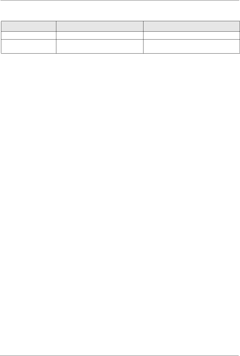
P-660H/HW-D Series User’s Guide
305 Appendix H Firewall Commands
config delete firewall set
<set #> rule<rule #>
This command removes the specified rule in a
firewall configuration set.
Table 128 Firewall Commands (continued)
FUNCTION COMMAND DESCRIPTION

P-660H/HW-D Series User’s Guide
Appendix I NetBIOS Filter Commands 306
APPENDIX I
NetBIOS Filter Commands
The following describes the NetBIOS packet filter commands.
Introduction
NetBIOS (Network Basic Input/Output System) are TCP or UDP broadcast packets that
enable a computer to connect to and communicate with a LAN.
For some dial-up services such as PPPoE or PPTP, NetBIOS packets cause unwanted calls.
You can configure NetBIOS filters to do the following:
• Allow or disallow the sending of NetBIOS packets from the LAN to the WAN and from
the WAN to the LAN.
• Allow or disallow the sending of NetBIOS packets through VPN connections.
• Allow or disallow NetBIOS packets to initiate calls.
Display NetBIOS Filter Settings
This command gives a read-only list of the current NetBIOS filter modes for The ZyXEL
Device.
NetBIOS Display Filter Settings Command Example
Syntax: sys filter netbios disp
=========== NetBIOS Filter Status ===========
Between LAN and WAN: Block
IPSec Packets: Forward
Trigger Dial: Disabled

P-660H/HW-D Series User’s Guide
307 Appendix I NetBIOS Filter Commands
The filter types and their default settings are as follows.
NetBIOS Filter Configuration
Syntax:sys filter netbios config <type> <on|off>
where
Table 129 NetBIOS Filter Default Settings
NAME DESCRIPTION EXAMPLE
Between LAN
and WAN
This field displays whether NetBIOS packets are blocked or forwarded
between the LAN and the WAN.
Block
IPSec Packets This field displays whether NetBIOS packets sent through a VPN
connection are blocked or forwarded.
Forward
Trigger dial This field displays whether NetBIOS packets are allowed to initiate
calls. Disabled means that NetBIOS packets are blocked from initiating
calls.
Disabled
<type> = Identify which NetBIOS filter (numbered 0-3) to configure.
0 = Between LAN and WAN
3 = IPSec packet pass through
4 = Trigger Dial
<on|off> = For type 0 and 1, use on to enable the filter and block NetBIOS
packets. Use off to disable the filter and forward NetBIOS packets.
For type 3, use on to block NetBIOS packets from being sent
through a VPN connection. Use off to allow NetBIOS packets to be
sent through a VPN connection.
For type 4, use on to allow NetBIOS packets to initiate dial backup
calls. Use off to block NetBIOS packets from initiating dial backup
calls.
Example commands
sys filter netbios
config 0 on
This command blocks LAN to WAN and WAN to LAN NetBIOS
packets.
sys filter netbios
config 3 on
This command blocks IPSec NetBIOS packets.
sys filter netbios
config 4 off
This command stops NetBIOS commands from initiating calls.
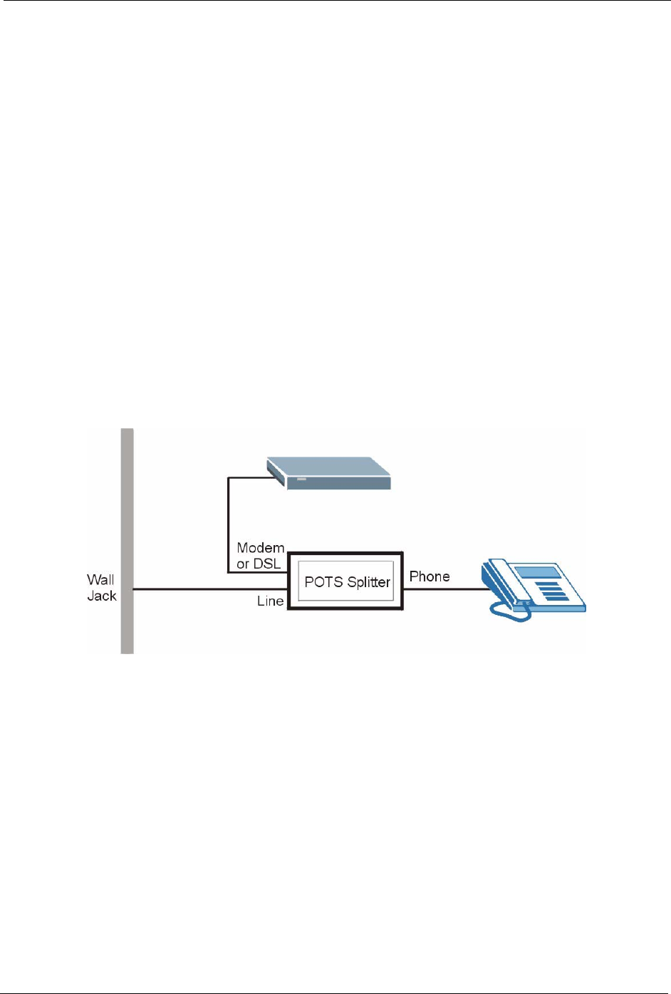
P-660H/HW-D Series User’s Guide
Appendix J Splitters and Microfilters 308
APPENDIX J
Splitters and Microfilters
This appendix tells you how to install a POTS splitter or a telephone microfilter.
Connecting a POTS Splitter
When you use the Full Rate (G.dmt) ADSL standard, you can use a POTS (Plain Old
Telephone Service) splitter to separate the telephone and ADSL signals. This allows
simultaneous Internet access and telephone service on the same line. A splitter also eliminates
the destructive interference conditions caused by telephone sets.
Install the POTS splitter at the point where the telephone line enters your residence, as shown
in the following figure.
Figure 179 Connecting a POTS Splitter
1Connect the side labeled “Phone” to your telephone.
2Connect the side labeled “Modem” or “DSL” to your ZyXEL Device.
3Connect the side labeled “Line” to the telephone wall jack.
Telephone Microfilters
Telephone voice transmissions take place in the lower frequency range, 0 - 4KHz, while
ADSL transmissions take place in the higher bandwidth range, above 4KHz. A microfilter acts
as a low-pass filter, for your telephone, to ensure that ADSL transmissions do not interfere
with your telephone voice transmissions. The use of a telephone microfilter is optional.
1Locate and disconnect each telephone.
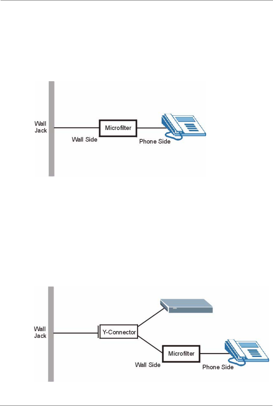
P-660H/HW-D Series User’s Guide
309 Appendix J Splitters and Microfilters
2Connect a cable from the wall jack to the “wall side” of the microfilter.
3Connect the “phone side” of the microfilter to your telephone as shown in the following
figure.
4After you are done, make sure that your telephone works. If your telephone does not
work, disconnect the microfilter and contact either your local telephone company or the
provider of the microfilter.
Figure 180 Connecting a Microfilter
You can also use a Y-Connector with a microfilter in order to connect both your modem and a
telephone to the same wall jack without using a POTS splitter.
1Connect a phone cable from the wall jack to the single jack end of the Y-Connector.
2Connect a cable from the double jack end of the Y-Connector to the “wall side” of the
microfilter.
3Connect another cable from the double jack end of the Y-Connector to the ZyXEL
Device.
4Connect the “phone side” of the microfilter to your telephone as shown in the following
figure.
Figure 181 Connecting a Microfilter and Y-Connector
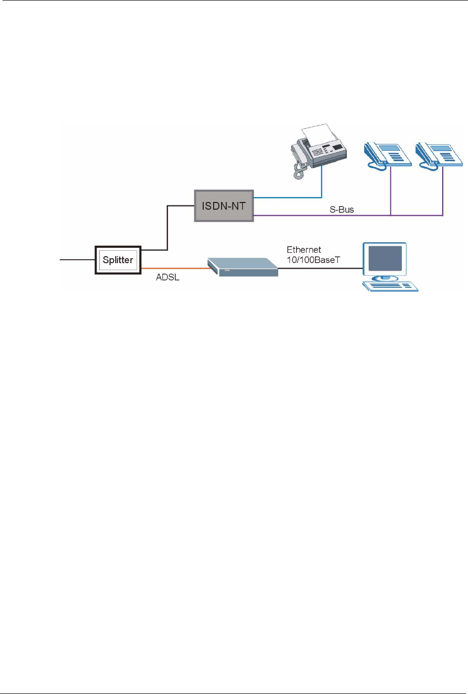
P-660H/HW-D Series User’s Guide
Appendix J Splitters and Microfilters 310
ZyXEL Device With ISDN
This section relates to people who use their ZyXEL Device with ADSL over ISDN (digital
telephone service) only. The following is an example installation for the ZyXEL Device with
ISDN.
Figure 182 ZyXEL Device with ISDN

P-660H/HW-D Series User’s Guide
311 Appendix J Splitters and Microfilters

P-660H/HW-D Series User’s Guide
Appendix K Log Descriptions 312
APPENDIX K
Log Descriptions
This appendix provides descriptions of example log messages.
Table 130 System Maintenance Logs
LOG MESSAGE DESCRIPTION
Time calibration is
successful
The router has adjusted its time based on information from the
time server.
Time calibration failed The router failed to get information from the time server.
WAN interface gets IP:%s A WAN interface got a new IP address from the DHCP,
PPPoE, PPTP or dial-up server.
DHCP client IP expired A DHCP client's IP address has expired.
DHCP server assigns%s The DHCP server assigned an IP address to a client.
Successful WEB login Someone has logged on to the router's web configurator
interface.
WEB login failed Someone has failed to log on to the router's web configurator
interface.
Successful TELNET login Someone has logged on to the router via telnet.
TELNET login failed Someone has failed to log on to the router via telnet.
Successful FTP login Someone has logged on to the router via ftp.
FTP login failed Someone has failed to log on to the router via ftp.
NAT Session Table is Full! The maximum number of NAT session table entries has been
exceeded and the table is full.
Starting Connectivity Monitor Starting Connectivity Monitor.
Time initialized by Daytime
Server
The router got the time and date from the Daytime server.
Time initialized by Time
server
The router got the time and date from the time server.
Time initialized by NTP
server
The router got the time and date from the NTP server.
Connect to Daytime server
fail
The router was not able to connect to the Daytime server.
Connect to Time server fail The router was not able to connect to the Time server.
Connect to NTP server fail The router was not able to connect to the NTP server.
Too large ICMP packet has
been dropped
The router dropped an ICMP packet that was too large.
Configuration Change: PC =
0x%x, Task ID = 0x%x
The router is saving configuration changes.
Successful SSH login Someone has logged on to the router’s SSH server.
SSH login failed Someone has failed to log on to the router’s SSH server.
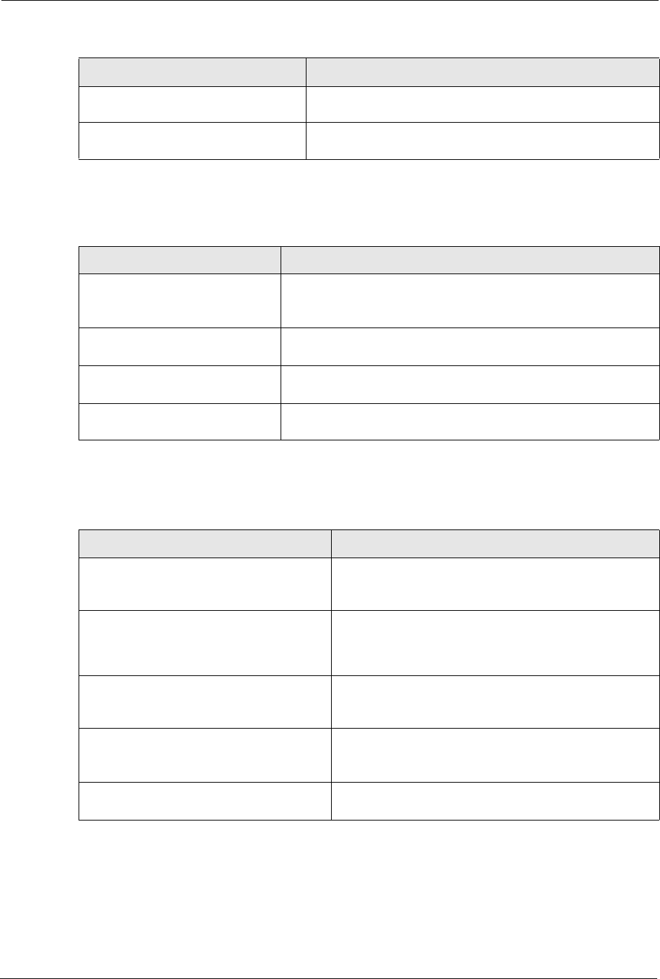
P-660H/HW-D Series User’s Guide
313 Appendix K Log Descriptions
Successful HTTPS login Someone has logged on to the router's web configurator
interface using HTTPS protocol.
HTTPS login failed Someone has failed to log on to the router's web configurator
interface using HTTPS protocol.
Table 131 System Error Logs
LOG MESSAGE DESCRIPTION
%s exceeds the max.
number of session per
host!
This attempt to create a NAT session exceeds the maximum
number of NAT session table entries allowed to be created per
host.
setNetBIOSFilter: calloc
error
The router failed to allocate memory for the NetBIOS filter settings.
readNetBIOSFilter: calloc
error
The router failed to allocate memory for the NetBIOS filter settings.
WAN connection is down. A WAN connection is down. You cannot access the network
through this interface.
Table 132 Access Control Logs
LOG MESSAGE DESCRIPTION
Firewall default policy: [TCP |
UDP | IGMP | ESP | GRE | OSPF]
<Packet Direction>
Attempted TCP/UDP/IGMP/ESP/GRE/OSPF access
matched the default policy and was blocked or forwarded
according to the default policy’s setting.
Firewall rule [NOT] match:[TCP |
UDP | IGMP | ESP | GRE | OSPF]
<Packet Direction>, <rule:%d>
Attempted TCP/UDP/IGMP/ESP/GRE/OSPF access
matched (or did not match) a configured firewall rule
(denoted by its number) and was blocked or forwarded
according to the rule.
Triangle route packet forwarded:
[TCP | UDP | IGMP | ESP | GRE |
OSPF]
The firewall allowed a triangle route session to pass
through.
Packet without a NAT table entry
blocked: [TCP | UDP | IGMP | ESP
| GRE | OSPF]
The router blocked a packet that didn't have a
corresponding NAT table entry.
Router sent blocked web site
message: TCP
The router sent a message to notify a user that the router
blocked access to a web site that the user requested.
Table 130 System Maintenance Logs (continued)
LOG MESSAGE DESCRIPTION