ZyXEL Communications USG20W-VPN VPN Firewall User Manual Book
ZyXEL Communications Corporation VPN Firewall Book
Contents
- 1. Users Manual Part 1
- 2. Users Manual Part 2
- 3. Users Manual Part 3
- 4. Users Manual Part 4
- 5. Users Manual Part 5
Users Manual Part 1

Quick Start Guide
www.zyxel.com
USG Series
USG20-VPN / USG20W-VPN
VPN Firewalls
Version 4.16
Edition 1, 12/2015
Copyright © 2015 ZyXEL Communications Corporation
User’s Guide
Default Login Details
LAN Port IP Address https://192.168.1.1
User Name admin
Password 1234

USG20(W)-VPN Series User’s Guide
2
Part I: User’s Guide .........................................................................................16
Chapter 1
Introduction.........................................................................................................................................18
1.1 Overview ...........................................................................................................................................18
1.1.1 Applications .............................................................................................................................18
1.2 Management Overview .....................................................................................................................20
1.3 Web Configurator ..............................................................................................................................22
1.3.1 Web Configurator Access ........................................................................................................22
1.3.2 Web Configurator Screens Overview ......................................................................................24
1.3.3 Navigation Panel .....................................................................................................................28
1.3.4 Tables and Lists .......................................................................................................................33
Chapter 2
Installation Setup Wizard ...................................................................................................................36
2.1 Installation Setup Wizard Screens ...................................................................................................36
2.1.1 Internet Access Setup - WAN Interface ..................................................................................36
2.1.2 Internet Access: Ethernet .......................................................................................................37
2.1.3 Internet Access: PPPoE ..........................................................................................................38
2.1.4 Internet Access: PPTP ...........................................................................................................40
2.1.5 Internet Access Setup - Second WAN Interface ......................................................................41
2.1.6 Internet Access Succeed ........................................................................................................42
2.1.7 Wireless Settings: SSID & Security ........................................................................................42
2.1.8 Internet Access - Device Registration ....................................................................................43
Chapter 3
Hardware, Interfaces and Zones .......................................................................................................44
3.1 Hardware Overview ...........................................................................................................................44
3.1.1 Front Panels ............................................................................................................................44
3.1.2 Rear Panels .............................................................................................................................45
3.1.3 Wall-mounting ..........................................................................................................................46
3.2 Default Zones, Interfaces, and Ports .................................................................................................47
3.3 Stopping the USG ............................................................................................................................48
Chapter 4
Quick Setup Wizards..........................................................................................................................49
4.1 Quick Setup Overview .......................................................................................................................49
4.2 WAN Interface Quick Setup ..............................................................................................................50
4.2.1 Choose an Ethernet Interface ..................................................................................................50
4.2.2 Select WAN Type .....................................................................................................................51
4.2.3 Configure WAN IP Settings .....................................................................................................51
4.2.4 ISP and WAN and ISP Connection Settings ............................................................................52
4.2.5 Quick Setup Interface Wizard: Summary ................................................................................54

USG20(W)-VPN Series User’s Guide
3
4.3 VPN Setup Wizard ............................................................................................................................55
4.3.1 Welcome ..................................................................................................................................56
4.3.2 VPN Setup Wizard: Wizard Type .............................................................................................57
4.3.3 VPN Express Wizard - Scenario .............................................................................................57
4.3.4 VPN Express Wizard - Configuration .....................................................................................59
4.3.5 VPN Express Wizard - Summary ...........................................................................................59
4.3.6 VPN Express Wizard - Finish .................................................................................................60
4.3.7 VPN Advanced Wizard - Scenario .........................................................................................61
4.3.8 VPN Advanced Wizard - Phase 1 Settings .............................................................................62
4.3.9 VPN Advanced Wizard - Phase 2 ...........................................................................................64
4.3.10 VPN Advanced Wizard - Summary ......................................................................................65
4.3.11 VPN Advanced Wizard - Finish .............................................................................................65
4.4 VPN Settings for Configuration Provisioning Wizard: Wizard Type ..................................................66
4.4.1 Configuration Provisioning Express Wizard - VPN Settings ...................................................67
4.4.2 Configuration Provisioning VPN Express Wizard - Configuration ..........................................68
4.4.3 VPN Settings for Configuration Provisioning Express Wizard - Summary .............................69
4.4.4 VPN Settings for Configuration Provisioning Express Wizard - Finish ...................................70
4.4.5 VPN Settings for Configuration Provisioning Advanced Wizard - Scenario ...........................71
4.4.6 VPN Settings for Configuration Provisioning Advanced Wizard - Phase 1 Settings ..............72
4.4.7 VPN Settings for Configuration Provisioning Advanced Wizard - Phase 2 ............................74
4.4.8 VPN Settings for Configuration Provisioning Advanced Wizard - Summary ..........................74
4.4.9 VPN Settings for Configuration Provisioning Advanced Wizard- Finish .................................76
4.5 VPN Settings for L2TP VPN Settings Wizard ...................................................................................77
4.5.1 L2TP VPN Settings ..................................................................................................................78
4.5.2 L2TP VPN Settings ..................................................................................................................79
4.5.3 VPN Settings for L2TP VPN Setting Wizard - Summary ........................................................80
4.5.4 VPN Settings for L2TP VPN Setting Wizard Completed ........................................................81
Chapter 5
Dashboard...........................................................................................................................................82
5.1 Overview ...........................................................................................................................................82
5.1.1 What You Can Do in this Chapter ............................................................................................82
5.2 Main Dashboard Screen ...................................................................................................................82
5.2.1 Device Information Screen ......................................................................................................84
5.2.2 System Status Screen .............................................................................................................85
5.2.3 VPN Status Screen ..................................................................................................................86
5.2.4 DHCP Table Screen ................................................................................................................87
5.2.5 Number of Login Users Screen ...............................................................................................88
5.2.6 System Resources Screen ......................................................................................................89
5.2.7 CPU Usage Screen .................................................................................................................90
5.2.8 Memory Usage Screen ............................................................................................................91
5.2.9 Active Session Screen .............................................................................................................92
5.2.10 Extension Slot Screen ...........................................................................................................93

USG20(W)-VPN Series User’s Guide
4
5.2.11 Interface Status Summary Screen .........................................................................................93
5.2.12 Secured Service Status Screen .............................................................................................94
5.2.13 Content Filter Statistics Screen .............................................................................................95
5.2.14 Top 5 IPv4/IPv6 Security Policy Rules that Blocked Traffic Screen .......................................96
5.2.15 The Latest Alert Logs Screen ................................................................................................96
Part II: Technical Reference............................................................................ 98
Chapter 6
Monitor...............................................................................................................................................100
6.1 Overview .........................................................................................................................................100
6.1.1 What You Can Do in this Chapter ..........................................................................................100
6.2 The Port Statistics Screen ..............................................................................................................101
6.2.1 The Port Statistics Graph Screen .........................................................................................102
6.3 Interface Status Screen ...................................................................................................................103
6.4 The Traffic Statistics Screen ............................................................................................................105
6.5 The Session Monitor Screen ..........................................................................................................108
6.6 IGMP Statistics ................................................................................................................................109
6.7 The DDNS Status Screen ............................................................................................................... 110
6.8 IP/MAC Binding ............................................................................................................................... 111
6.9 The Login Users Screen ................................................................................................................ 111
6.10 Cellular Status Screen ................................................................................................................... 112
6.11 The UPnP Port Status Screen ...................................................................................................... 114
6.12 USB Storage Screen ..................................................................................................................... 115
6.13 Ethernet Neighbor Screen ............................................................................................................ 116
6.14 Wireless ....................................................................................................................................... 117
6.14.1 Wireless AP Information: Radio List .................................................................................... 117
6.14.2 Radio List More Information ................................................................................................ 119
6.14.3 Wireless Station Info ............................................................................................................120
6.14.4 Detected Device .................................................................................................................121
6.15 The IPSec Monitor Screen ............................................................................................................122
6.15.1 Regular Expressions in Searching IPSec SAs ....................................................................123
6.16 The SSL Screen ............................................................................................................................123
6.17 The L2TP over IPSec Session Monitor Screen .............................................................................124
6.18 The Content Filter Screen .............................................................................................................125
6.19 The Anti-Spam Screens ................................................................................................................127
6.19.1 Anti-Spam Report ................................................................................................................127
6.19.2 The Anti-Spam Status Screen .............................................................................................129
6.20 Log Screens ..................................................................................................................................130
6.20.1 View Log ..............................................................................................................................130

USG20(W)-VPN Series User’s Guide
5
Chapter 7
Licensing...........................................................................................................................................133
7.1 Registration Overview .....................................................................................................................133
7.1.1 What you Need to Know ........................................................................................................133
7.1.2 Registration Screen ...............................................................................................................134
7.1.3 Service Screen ......................................................................................................................134
Chapter 8
Wireless.............................................................................................................................................136
8.1 Overview .........................................................................................................................................136
8.1.1 What You Can Do in this Chapter ..........................................................................................136
8.1.2 What You Need to Know ........................................................................................................136
8.2 AP Management Screen ................................................................................................................137
8.3 DCS Screen ...................................................................................................................................138
8.4 Technical Reference ........................................................................................................................138
8.4.1 Dynamic Channel Selection ..................................................................................................138
Chapter 9
Interfaces...........................................................................................................................................140
9.1 Interface Overview ..........................................................................................................................140
9.1.1 What You Can Do in this Chapter ..........................................................................................140
9.1.2 What You Need to Know ........................................................................................................141
9.1.3 What You Need to Do First ....................................................................................................145
9.2 Port Role Screen .............................................................................................................................145
9.3 Ethernet Summary Screen ..............................................................................................................146
9.3.1 Ethernet Edit .........................................................................................................................148
9.3.2 Object References .................................................................................................................163
9.3.3 Add/Edit DHCPv6 Request/Release Options ........................................................................164
9.3.4 Add/Edit DHCP Extended Options ........................................................................................165
9.4 PPP Interfaces ................................................................................................................................166
9.4.1 PPP Interface Summary ........................................................................................................167
9.4.2 PPP Interface Add or Edit .....................................................................................................168
9.5 Cellular Configuration Screen .........................................................................................................173
9.5.1 Cellular Choose Slot .............................................................................................................176
9.5.2 Add / Edit Cellular Configuration ...........................................................................................176
9.6 Tunnel Interfaces ............................................................................................................................182
9.6.1 Configuring a Tunnel .............................................................................................................184
9.6.2 Tunnel Add or Edit Screen .....................................................................................................185
9.7 VLAN Interfaces .............................................................................................................................188
9.7.1 VLAN Summary Screen ........................................................................................................190
9.7.2 VLAN Add/Edit ......................................................................................................................192
9.8 Bridge Interfaces ............................................................................................................................201
9.8.1 Bridge Summary ....................................................................................................................203

USG20(W)-VPN Series User’s Guide
6
9.8.2 Bridge Add/Edit .....................................................................................................................204
9.9 Virtual Interfaces ............................................................................................................................213
9.9.1 Virtual Interfaces Add/Edit .....................................................................................................213
9.10 Interface Technical Reference .......................................................................................................215
9.11 Trunk Overview ............................................................................................................................218
9.11.1 What You Need to Know ......................................................................................................218
9.12 The Trunk Summary Screen .........................................................................................................221
9.12.1 Configuring a User-Defined Trunk .......................................................................................222
9.12.2 Configuring the System Default Trunk ................................................................................224
Chapter 10
Routing ..............................................................................................................................................226
10.1 Policy and Static Routes Overview ...............................................................................................226
10.1.1 What You Can Do in this Chapter ........................................................................................226
10.1.2 What You Need to Know .....................................................................................................227
10.2 Policy Route Screen ......................................................................................................................228
10.2.1 Policy Route Edit Screen .....................................................................................................230
10.3 IP Static Route Screen ..................................................................................................................235
10.3.1 Static Route Add/Edit Screen ..............................................................................................235
10.4 Policy Routing Technical Reference ..............................................................................................237
10.5 Routing Protocols Overview .........................................................................................................238
10.5.1 What You Need to Know ......................................................................................................238
10.6 The RIP Screen .............................................................................................................................238
10.7 The OSPF Screen .........................................................................................................................240
10.7.1 Configuring the OSPF Screen .............................................................................................243
10.7.2 OSPF Area Add/Edit Screen ..............................................................................................244
10.7.3 Virtual Link Add/Edit Screen ...............................................................................................246
10.8 Routing Protocol Technical Reference ..........................................................................................247
Chapter 11
DDNS................................................................................................................................................249
11.1 DDNS Overview ............................................................................................................................249
11.1.1 What You Can Do in this Chapter ........................................................................................249
11.1.2 What You Need to Know ......................................................................................................249
11.2 The DDNS Screen .........................................................................................................................250
11.2.1 The Dynamic DNS Add/Edit Screen ....................................................................................251
Chapter 12
NAT.....................................................................................................................................................255
12.1 NAT Overview ...............................................................................................................................255
12.1.1 What You Can Do in this Chapter ........................................................................................255
12.1.2 What You Need to Know ......................................................................................................255
12.2 The NAT Screen ............................................................................................................................255

USG20(W)-VPN Series User’s Guide
7
12.2.1 The NAT Add/Edit Screen ....................................................................................................257
12.3 NAT Technical Reference ..............................................................................................................260
Chapter 13
HTTP Redirect...................................................................................................................................262
13.1 Overview .......................................................................................................................................262
13.1.1 What You Can Do in this Chapter ........................................................................................262
13.1.2 What You Need to Know ......................................................................................................262
13.2 The HTTP Redirect Screen ...........................................................................................................263
13.2.1 The HTTP Redirect Edit Screen ..........................................................................................264
Chapter 14
ALG ....................................................................................................................................................266
14.1 ALG Overview ...............................................................................................................................266
14.1.1 What You Need to Know ......................................................................................................266
14.1.2 Before You Begin .................................................................................................................269
14.2 The ALG Screen ...........................................................................................................................269
14.3 ALG Technical Reference .............................................................................................................271
Chapter 15
UPnP ..................................................................................................................................................273
15.1 UPnP and NAT-PMP Overview .....................................................................................................273
15.2 What You Need to Know ...............................................................................................................273
15.2.1 NAT Traversal ......................................................................................................................273
15.2.2 Cautions with UPnP and NAT-PMP .....................................................................................274
15.3 UPnP Screen ................................................................................................................................274
15.4 Technical Reference ......................................................................................................................275
15.4.1 Turning on UPnP in Windows 7 Example ............................................................................275
15.4.2 Using UPnP in Windows XP Example .................................................................................277
15.4.3 Web Configurator Easy Access ...........................................................................................279
Chapter 16
IP/MAC Binding.................................................................................................................................282
16.1 IP/MAC Binding Overview .............................................................................................................282
16.1.1 What You Can Do in this Chapter ........................................................................................282
16.1.2 What You Need to Know ......................................................................................................282
16.2 IP/MAC Binding Summary ............................................................................................................283
16.2.1 IP/MAC Binding Edit ............................................................................................................283
16.2.2 Static DHCP Edit .................................................................................................................284
16.3 IP/MAC Binding Exempt List .........................................................................................................285
Chapter 17
Layer 2 Isolation ...............................................................................................................................287

USG20(W)-VPN Series User’s Guide
8
17.1 Overview .......................................................................................................................................287
17.1.1 What You Can Do in this Chapter ........................................................................................287
17.2 Layer-2 Isolation General Screen ................................................................................................288
17.3 White List Screen ..........................................................................................................................288
17.3.1 Add/Edit White List Rule .....................................................................................................289
Chapter 18
Inbound Load Balancing..................................................................................................................291
18.1 Inbound Load Balancing Overview ...............................................................................................291
18.1.1 What You Can Do in this Chapter ........................................................................................291
18.2 The Inbound LB Screen ................................................................................................................292
18.2.1 The Inbound LB Add/Edit Screen ........................................................................................293
18.2.2 The Inbound LB Member Add/Edit Screen ..........................................................................295
Chapter 19
Web Authentication .........................................................................................................................297
19.1 Web Auth Overview ......................................................................................................................297
19.1.1 What You Can Do in this Chapter ........................................................................................297
19.1.2 What You Need to Know ......................................................................................................298
19.2 Web Authentication Screen ...........................................................................................................298
19.2.1 Creating Exceptional Services .............................................................................................301
19.2.2 Creating/Editing an Authentication Policy ............................................................................301
19.3 SSO Overview ...............................................................................................................................302
19.4 SSO - USG Configuration .............................................................................................................304
19.4.1 Configuration Overview .......................................................................................................304
19.4.2 Configure the USG to Communicate with SSO ...................................................................304
19.4.3 Enable Web Authentication .................................................................................................305
19.4.4 Create a Security Policy ......................................................................................................306
19.4.5 Configure User Information .................................................................................................307
19.4.6 Configure an Authentication Method ...................................................................................308
19.4.7 Configure Active Directory ...................................................................................................309
19.5 SSO Agent Configuration ..............................................................................................................310
Chapter 20
Security Policy..................................................................................................................................314
20.1 Overview .......................................................................................................................................314
20.2 One Security .................................................................................................................................314
20.3 What You Can Do in this Chapter .................................................................................................318
20.3.1 What You Need to Know ......................................................................................................318
20.4 The Security Policy Screen ...........................................................................................................320
20.4.1 Configuring the Security Policy Control Screen ...................................................................321
20.4.2 The Security Policy Control Add/Edit Screen ......................................................................324
20.5 The Session Control Screen .........................................................................................................326

USG20(W)-VPN Series User’s Guide
9
20.5.1 The Session Control Add/Edit Screen .................................................................................328
20.6 Security Policy Example Applications ...........................................................................................329
Chapter 21
IPSec VPN..........................................................................................................................................332
21.1 Virtual Private Networks (VPN) Overview .....................................................................................332
21.1.1 What You Can Do in this Chapter ........................................................................................334
21.1.2 What You Need to Know ......................................................................................................335
21.1.3 Before You Begin .................................................................................................................336
21.2 The VPN Connection Screen ........................................................................................................337
21.2.1 The VPN Connection Add/Edit (IKE) Screen .......................................................................338
21.3 The VPN Gateway Screen ............................................................................................................344
21.3.1 The VPN Gateway Add/Edit Screen ....................................................................................346
21.4 VPN Concentrator ........................................................................................................................353
21.4.1 VPN Concentrator Requirements and Suggestions ............................................................353
21.4.2 VPN Concentrator Screen ...................................................................................................354
21.4.3 The VPN Concentrator Add/Edit Screen .............................................................................354
21.5 USG IPSec VPN Client Configuration Provisioning ......................................................................355
21.6 IPSec VPN Background Information .............................................................................................357
Chapter 22
SSL VPN ............................................................................................................................................367
22.1 Overview .......................................................................................................................................367
22.1.1 What You Can Do in this Chapter ........................................................................................367
22.1.2 What You Need to Know ......................................................................................................367
22.2 The SSL Access Privilege Screen ................................................................................................368
22.2.1 The SSL Access Privilege Policy Add/Edit Screen .............................................................369
22.3 The SSL Global Setting Screen ....................................................................................................372
22.3.1 How to Upload a Custom Logo ............................................................................................373
22.4 USG SecuExtender .......................................................................................................................374
22.4.1 Example: Configure USG for SecuExtender .......................................................................375
Chapter 23
SSL User Screens.............................................................................................................................378
23.1 Overview .......................................................................................................................................378
23.1.1 What You Need to Know ......................................................................................................378
23.2 Remote SSL User Login ...............................................................................................................379
23.3 The SSL VPN User Screens .........................................................................................................382
23.4 Bookmarking the USG ..................................................................................................................383
23.5 Logging Out of the SSL VPN User Screens ..................................................................................384
23.6 SSL User Application Screen ........................................................................................................384
23.7 SSL User File Sharing ...................................................................................................................385
23.7.1 The Main File Sharing Screen .............................................................................................385

USG20(W)-VPN Series User’s Guide
10
23.7.2 Opening a File or Folder ......................................................................................................386
23.7.3 Downloading a File ..............................................................................................................387
23.7.4 Saving a File ........................................................................................................................387
23.7.5 Creating a New Folder .........................................................................................................388
23.7.6 Renaming a File or Folder ...................................................................................................388
23.7.7 Deleting a File or Folder ......................................................................................................389
23.7.8 Uploading a File ...................................................................................................................389
Chapter 24
USG SecuExtender (Windows)........................................................................................................391
24.1 The USG SecuExtender Icon ........................................................................................................391
24.2 Status ............................................................................................................................................391
24.3 View Log .......................................................................................................................................392
24.4 Suspend and Resume the Connection .........................................................................................393
24.5 Stop the Connection ......................................................................................................................393
24.6 Uninstalling the USG SecuExtender .............................................................................................393
Chapter 25
L2TP VPN...........................................................................................................................................395
25.1 Overview .......................................................................................................................................395
25.1.1 What You Can Do in this Chapter ........................................................................................395
25.1.2 What You Need to Know ......................................................................................................395
25.2 L2TP VPN Screen .........................................................................................................................396
25.2.1 Example: L2TP and USG Behind a NAT Router .................................................................398
Chapter 26
BWM (Bandwidth Management) ...................................................................................................400
26.1 Overview .......................................................................................................................................400
26.1.1 What You Can Do in this Chapter ........................................................................................400
26.1.2 What You Need to Know .....................................................................................................400
26.2 The Bandwidth Management Screen ............................................................................................404
26.2.1 The Bandwidth Management Add/Edit Screen ....................................................................406
Chapter 27
Content Filtering...............................................................................................................................415
27.1 Overview .......................................................................................................................................415
27.1.1 What You Can Do in this Chapter ........................................................................................415
27.1.2 What You Need to Know ......................................................................................................415
27.1.3 Before You Begin .................................................................................................................416
27.2 Content Filter Profile Screen .........................................................................................................417
27.3 Content Filter Profile Add or Edit Screen ......................................................................................419
27.3.1 Content Filter Add Profile Category Service ........................................................................420
27.3.2 Content Filter Add Filter Profile Custom Service ................................................................427

USG20(W)-VPN Series User’s Guide
11
27.4 Content Filter Trusted Web Sites Screen .....................................................................................430
27.5 Content Filter Forbidden Web Sites Screen .................................................................................431
27.6 Content Filter Technical Reference ...............................................................................................432
Chapter 28
Anti-Spam..........................................................................................................................................434
28.1 Overview .......................................................................................................................................434
28.1.1 What You Can Do in this Chapter ........................................................................................434
28.1.2 What You Need to Know ......................................................................................................434
28.2 Before You Begin ..........................................................................................................................435
28.3 The Anti-Spam Profile Screen .......................................................................................................436
28.3.1 The Anti-Spam Profile Add or Edit Screen ..........................................................................437
28.4 The Mail Scan Screen ...................................................................................................................439
28.5 The Anti-Spam Black List Screen ..................................................................................................441
28.5.1 The Anti-Spam Black or White List Add/Edit Screen ...........................................................443
28.5.2 Regular Expressions in Black or White List Entries .............................................................444
28.6 The Anti-Spam White List Screen .................................................................................................444
28.7 The DNSBL Screen .......................................................................................................................446
28.8 Anti-Spam Technical Reference ....................................................................................................448
Chapter 29
Object.................................................................................................................................................452
29.1 Zones Overview ............................................................................................................................452
29.1.1 What You Need to Know ......................................................................................................452
29.1.2 The Zone Screen .................................................................................................................453
29.2 User/Group Overview ....................................................................................................................454
29.2.1 What You Need To Know .....................................................................................................455
29.2.2 User/Group User Summary Screen .....................................................................................457
29.2.3 User/Group Group Summary Screen ..................................................................................460
29.2.4 User/Group Setting Screen ................................................................................................461
29.2.5 User/Group MAC Address Summary Screen .....................................................................466
29.2.6 User /Group Technical Reference .......................................................................................467
29.3 AP Profile Overview ......................................................................................................................468
29.3.1 Radio Screen .......................................................................................................................469
29.3.2 SSID Screen .......................................................................................................................475
29.4 MON Profile ..................................................................................................................................484
29.4.1 Overview ..............................................................................................................................484
29.4.2 MON Profile .........................................................................................................................484
29.5 Address Overview .........................................................................................................................487
29.5.1 What You Need To Know .....................................................................................................487
29.5.2 Address Summary Screen ...................................................................................................487
29.6 Service Overview ..........................................................................................................................491
29.6.1 What You Need to Know ......................................................................................................492

USG20(W)-VPN Series User’s Guide
12
29.6.2 The Service Summary Screen .............................................................................................492
29.6.3 The Service Group Summary Screen .................................................................................494
29.7 Schedule Overview ......................................................................................................................496
29.7.1 What You Need to Know ......................................................................................................496
29.7.2 The Schedule Summary Screen ..........................................................................................497
29.7.3 The Schedule Group Screen ...............................................................................................500
29.8 AAA Server Overview .................................................................................................................501
29.8.1 Directory Service (AD/LDAP) ..............................................................................................502
29.8.2 RADIUS Server ...................................................................................................................502
29.8.3 ASAS ...................................................................................................................................502
29.8.4 What You Need To Know .....................................................................................................503
29.8.5 Active Directory or LDAP Server Summary .........................................................................504
29.8.6 RADIUS Server Summary ...................................................................................................508
29.9 Auth. Method Overview ...............................................................................................................510
29.9.1 Before You Begin .................................................................................................................510
29.9.2 Example: Selecting a VPN Authentication Method ..............................................................510
29.9.3 Authentication Method Objects ............................................................................................ 511
29.10 Certificate Overview ...................................................................................................................513
29.10.1 What You Need to Know ....................................................................................................513
29.10.2 Verifying a Certificate .........................................................................................................515
29.10.3 The My Certificates Screen ...............................................................................................516
29.10.4 The Trusted Certificates Screen .......................................................................................523
29.10.5 Certificates Technical Reference .......................................................................................528
29.11 ISP Account Overview ................................................................................................................528
29.11.1 ISP Account Summary .......................................................................................................528
29.12 SSL Application Overview ..........................................................................................................531
29.12.1 What You Need to Know ....................................................................................................531
29.12.2 The SSL Application Screen ..............................................................................................533
Chapter 30
System...............................................................................................................................................537
30.1 Overview .......................................................................................................................................537
30.1.1 What You Can Do in this Chapter ........................................................................................537
30.2 Host Name ....................................................................................................................................538
30.3 USB Storage .................................................................................................................................538
30.4 Date and Time ...............................................................................................................................539
30.4.1 Pre-defined NTP Time Servers List .....................................................................................542
30.4.2 Time Server Synchronization ...............................................................................................542
30.5 Console Port Speed ......................................................................................................................543
30.6 DNS Overview ...............................................................................................................................544
30.6.1 DNS Server Address Assignment .......................................................................................544
30.6.2 Configuring the DNS Screen ...............................................................................................544
30.6.3 Address Record ..................................................................................................................547

USG20(W)-VPN Series User’s Guide
13
30.6.4 PTR Record .........................................................................................................................548
30.6.5 Adding an Address/PTR Record .........................................................................................548
30.6.6 CNAME Record ...................................................................................................................548
30.6.7 Adding a CNAME Record ....................................................................................................549
30.6.8 Domain Zone Forwarder .....................................................................................................549
30.6.9 Adding a Domain Zone Forwarder ......................................................................................549
30.6.10 MX Record ........................................................................................................................550
30.6.11 Adding a MX Record ..........................................................................................................551
30.6.12 Security Option Control .....................................................................................................551
30.6.13 Editing a Security Option Control ......................................................................................551
30.6.14 Adding a DNS Service Control Rule ..................................................................................552
30.7 WWW Overview ............................................................................................................................553
30.7.1 Service Access Limitations ..................................................................................................553
30.7.2 System Timeout ...................................................................................................................554
30.7.3 HTTPS .................................................................................................................................554
30.7.4 Configuring WWW Service Control .....................................................................................555
30.7.5 Service Control Rules ..........................................................................................................558
30.7.6 Customizing the WWW Login Page ....................................................................................559
30.7.7 HTTPS Example ..................................................................................................................562
30.8 SSH ............................................................................................................................................569
30.8.1 How SSH Works ..................................................................................................................570
30.8.2 SSH Implementation on the USG ........................................................................................571
30.8.3 Requirements for Using SSH ...............................................................................................571
30.8.4 Configuring SSH ..................................................................................................................571
30.8.5 Secure Telnet Using SSH Examples ...................................................................................572
30.9 Telnet ............................................................................................................................................573
30.9.1 Configuring Telnet ................................................................................................................573
30.10 FTP ............................................................................................................................................575
30.10.1 Configuring FTP ................................................................................................................575
30.11 SNMP .........................................................................................................................................576
30.11.1 SNMPv3 and Security ........................................................................................................577
30.11.2 Supported MIBs .................................................................................................................577
30.11.3 SNMP Traps ......................................................................................................................577
30.11.4 Configuring SNMP .............................................................................................................578
30.12 Authentication Server ..................................................................................................................580
30.12.1 Add/Edit Trusted RADIUS Client ......................................................................................581
30.13 CloudCNM Screen ......................................................................................................................582
30.14 Language Screen ........................................................................................................................585
30.15 IPv6 Screen .................................................................................................................................585
30.16 ZyXEL One Network (ZON) Utility ..............................................................................................586
30.16.1 ZyXEL One Network (ZON) System Screen .....................................................................587
Chapter 31
Log and Report .................................................................................................................................589

USG20(W)-VPN Series User’s Guide
14
31.1 Overview .......................................................................................................................................589
31.1.1 What You Can Do In this Chapter ........................................................................................589
31.2 Email Daily Report ........................................................................................................................589
31.3 Log Setting Screens .....................................................................................................................591
31.3.1 Log Settings .........................................................................................................................592
31.3.2 Edit System Log Settings ...................................................................................................593
31.3.3 Edit Log on USB Storage Setting .......................................................................................596
31.3.4 Edit Remote Server Log Settings .......................................................................................598
31.3.5 Log Category Settings Screen .............................................................................................600
Chapter 32
File Manager......................................................................................................................................604
32.1 Overview .......................................................................................................................................604
32.1.1 What You Can Do in this Chapter ........................................................................................604
32.1.2 What you Need to Know ......................................................................................................604
32.2 The Configuration File Screen ......................................................................................................606
32.3 The Firmware Package Screen ....................................................................................................610
32.4 The Shell Script Screen ...............................................................................................................612
Chapter 33
Diagnostics ......................................................................................................................................615
33.1 Overview .......................................................................................................................................615
33.1.1 What You Can Do in this Chapter ........................................................................................615
33.2 The Diagnostic Screen ..................................................................................................................615
33.2.1 The Diagnostics Files Screen ..............................................................................................616
33.3 The Packet Capture Screen ..........................................................................................................617
33.3.1 The Packet Capture Files Screen ........................................................................................620
33.4 The Core Dump Screen ................................................................................................................620
33.4.1 The Core Dump Files Screen .............................................................................................621
33.5 The System Log Screen ................................................................................................................622
33.6 The Network Tool Screen ..............................................................................................................622
33.7 The Wireless Frame Capture Screen ...........................................................................................623
33.7.1 The Wireless Frame Capture Files Screen ........................................................................625
Chapter 34
Packet Flow Explore ........................................................................................................................627
34.1 Overview .......................................................................................................................................627
34.1.1 What You Can Do in this Chapter ........................................................................................627
34.2 The Routing Status Screen ...........................................................................................................627
34.3 The SNAT Status Screen ..............................................................................................................632
Chapter 35
Shutdown...........................................................................................................................................635

USG20(W)-VPN Series User’s Guide
15
35.1 Overview .......................................................................................................................................635
35.1.1 What You Need To Know .....................................................................................................635
35.2 The Shutdown Screen ...................................................................................................................635
Chapter 36
Troubleshooting................................................................................................................................636
36.1 Resetting the USG ........................................................................................................................644
36.2 Getting More Troubleshooting Help ..............................................................................................645
Appendix A Customer Support ........................................................................................................646
Appendix B Legal Information..........................................................................................................652
Appendix C Product Features..........................................................................................................661
Index ..................................................................................................................................................665

16
PART I
User’s Guide

17
USG20(W)-VPN Series User’s Guide
18
CHAPTER 1
Introduction
1.1 Overview
“USG” in this User’s Guide refers to all USG models in the series.
USG20W-VPN has built-in Wi-Fi functionality
•See Table 12 on page 47 for default port / interface name mapping. See Table 13 on page 48 for
default interface / zone mapping.
See the product’s datasheet for detailed information on a specific model.
1.1.1 Applications
These are some USG application scenarios.
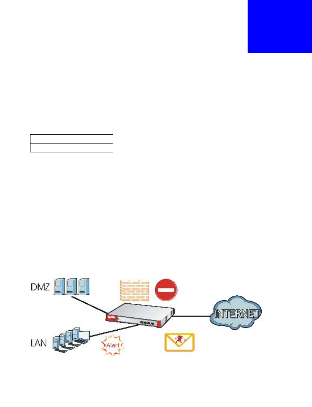
Security Router
Security includes a Stateful Packet Inspection (SPI) firewall, Content Filtering (CF) and Anti-Spam
(AS).
Figure 1 Applications: Security RouterApplications: Security Router
Table 1 USG Models
USG20-VPN
USG20W-VPN
Chapter 1 Introduction
USG20(W)-VPN Series User’s Guide
19
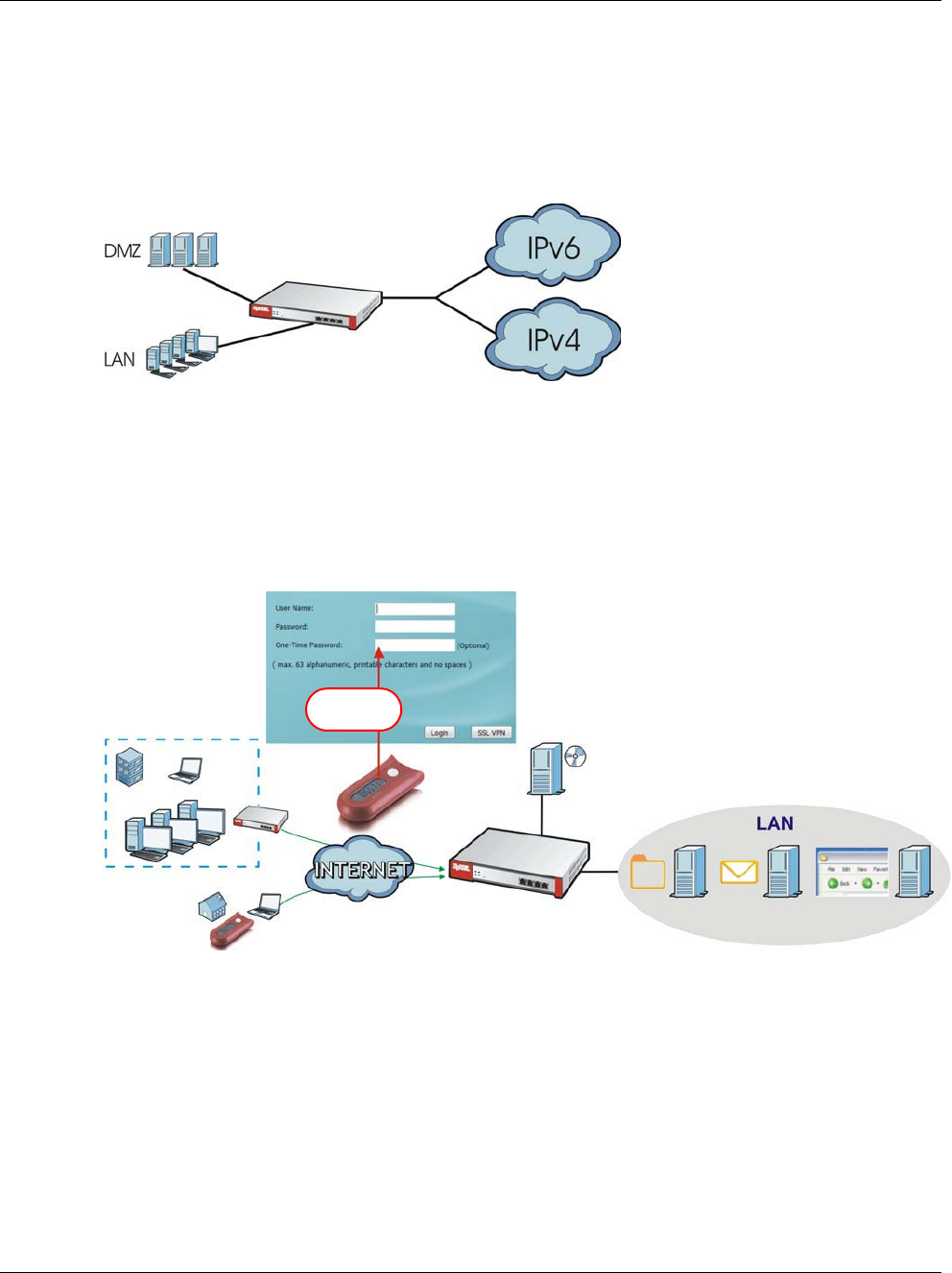
IPv6 Routing
The USG supports IPv6 Ethernet, PPP, VLAN, and bridge routing. You may also create IPv6 policy
routes and IPv6 objects. The USG can also route IPv6 packets through IPv4 networks using
different tunneling methods.
Figure 2 Applications: IPv6 Routing
VPN Connectivity
Set up VPN tunnels with other companies, branch offices, telecommuters, and business travelers to
provide secure access to your network. You can also purchase the USG OTPv2 One-Time Password
System for strong two-factor authentication for Web Configurator, Web access, SSL VPN, and ZyXEL
IPSec VPN client user logins.
Figure 3 Applications: VPN Connectivity
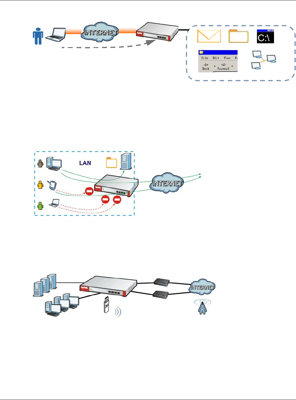
SSL VPN Network Access
SSL VPN lets remote users use their web browsers for a very easy-to-use VPN solution. A user just
browses to the USG’s web address and enters his user name and password to securely connect to
the USG’s network. Here full tunnel mode creates a virtual connection for a remote user and gives
him a private IP address in the same subnet as the local network so he can access network
resources in the same way as if he were part of the internal network.
OTP PIN
SafeWord 2008
Authentication Server
File Email Web-based
Server Server Application
*****
Chapter 1 Introduction
USG20(W)-VPN Series User’s Guide
20
Figure 4 SSL VPN With Full Tunnel Mode
User-Aware Access Control
Set up security policies to restrict access to sensitive information and shared resources based on
the user who is trying to access it. In the following figure user A can access both the Internet and
an internal file server. User B has a lower level of access and can only access the Internet. User C is
not even logged in, so and cannot access either the Internet or the file server.
Figure 5 Applications: User-Aware Access Control
Load Balancing
Set up multiple connections to the Internet on the same port, or different ports, including cellular
interfaces. In either case, you can balance the traffic loads between them.
Figure 6 Applications: Multiple WAN Interfaces
1.2 Management Overview
You can manage the USG in the following ways.
Web Mail File Share
Web-based Application
https://
Application Server
Non-Web
LAN (192.168.1.X)
A
B
C
Chapter 1 Introduction
USG20(W)-VPN Series User’s Guide
21
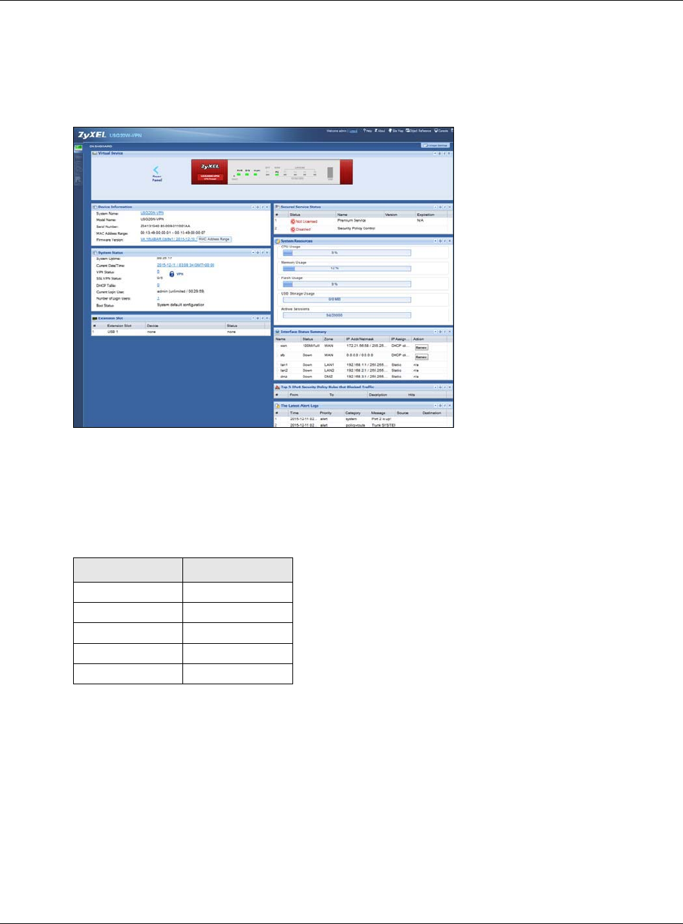
Web Configurator
The Web Configurator allows easy USG setup and management using an Internet browser. This
User’s Guide provides information about the Web Configurator.
Figure 7 Managing the USG: Web Configurator
Command-Line Interface (CLI)
The CLI allows you to use text-based commands to configure the USG. Access it using remote
management (for example, SSH or Telnet) or via the physical or Web Configurator console port.
See the Command Reference Guide for CLI details. The default settings for the console port are:
FTP
Use File Transfer Protocol for firmware upgrades and configuration backup/restore.
SNMP
The device can be monitored and/or managed by an SNMP manager. See Section 30.11 on page
576.
Table 2 Console Port Default Settings
SETTING VALUE
Speed 115200 bps
Data Bits 8
Parity None
Stop Bit 1
Flow Control Off
Chapter 1 Introduction
USG20(W)-VPN Series User’s Guide
22
Cloud CNM
Use the CloudCNM screen (see Section 30.13 on page 582) to enable and configure management
of the USG by a Central Network Management system.
1.3 Web Configurator
In order to use the Web Configurator, you must:
• Use one of the following web browser versions or later: Internet Explorer 7, Firefox 3.5, Chrome
9.0
• Allow pop-up windows (blocked by default in Windows XP Service Pack 2)
• Enable JavaScripts, Java permissions, and cookies
The recommended screen resolution is 1024 x 768 pixels.
1.3.1 Web Configurator Access
1Make sure your USG hardware is properly connected. See the Quick Start Guide.
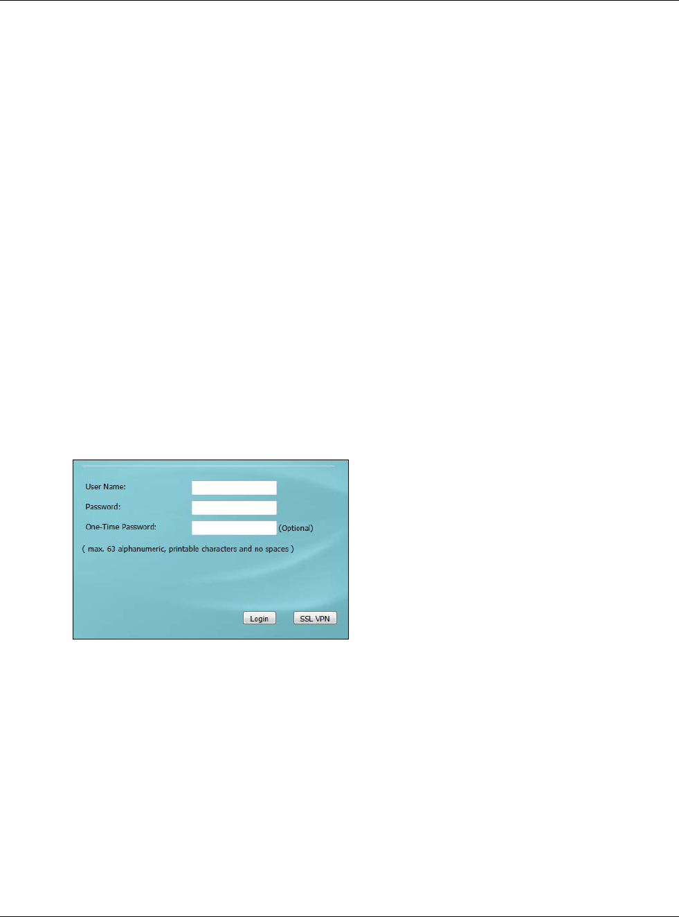
2In your browser go to http://192.168.1.1. By default, the USG automatically routes this request to
its HTTPS server, and it is recommended to keep this setting. The Login screen appears.
3Type the user name (default: “admin”) and password (default: “1234”).
If you have a OTP (One-Time Password) token generate a number and enter it in the One-Time
Password field. The number is only good for one login. You must use the token to generate a new
number the next time you log in.
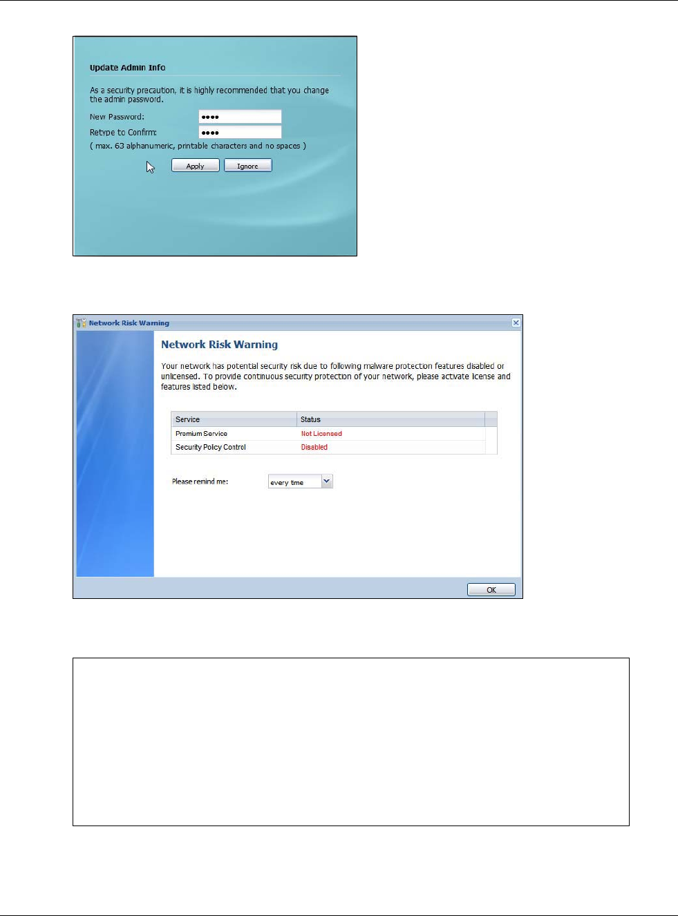
4Click Login. If you logged in using the default user name and password, the Update Admin Info
screen appears. Otherwise, the dashboard appears.
Chapter 1 Introduction
USG20(W)-VPN Series User’s Guide
23
5The Network Risk Warning screen displays any unregistered or disabled security services. Select
how often to display the screen and click OK.
If you select Never and you later want to bring this screen back, use these commands (note the
space before the underscore).
See the Command Line Interface (CLI) Reference Guide (RG) for details on all supported
commands.
Router> enable
Router#
Router# configure terminal
Router(config)#
Router(config)# service-register _setremind
after-10-days
after-180-days
after-30-days
every-time
never
Router(config)# service-register _setremind every-time
Router(config)#
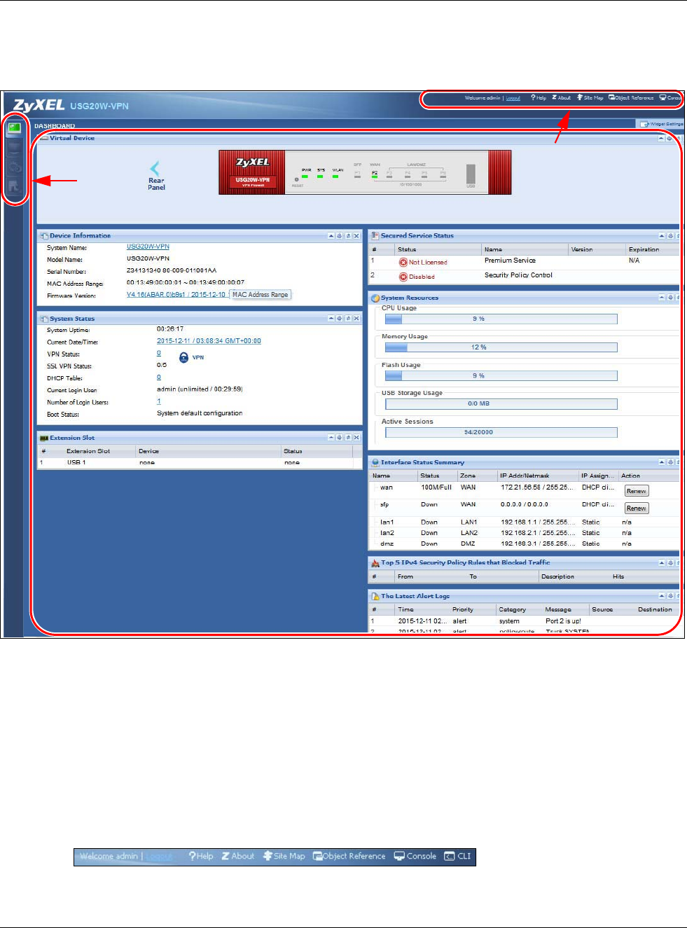
Chapter 1 Introduction
USG20(W)-VPN Series User’s Guide
24
6Follow the directions in the Update Admin Info screen. If you change the default password, the
Login screen appears after you click Apply. If you click Ignore, the Installation Setup Wizard
opens if the USG is using its default configuration; otherwise the dashboard appears.
1.3.2 Web Configurator Screens Overview
The Web Configurator screen is divided into these parts (as illustrated on page 24):
•A - title bar
•B - navigation panel
•C - main window
Title Bar
Figure 8 Title Bar
A
C
B
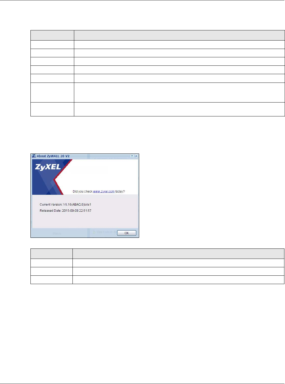
Chapter 1 Introduction
USG20(W)-VPN Series User’s Guide
25
The title bar icons in the upper right corner provide the following functions.
About
Click About to display basic information about the USG.
Figure 9 About
Site Map
Click Site MAP to see an overview of links to the Web Configurator screens. Click a screen’s link to
go to that screen.
Table 3 Title Bar: Web Configurator Icons
LABEL DESCRIPTION
Logout Click this to log out of the Web Configurator.
Help Click this to open the help page for the current screen.
About Click this to display basic information about the USG.
Site Map Click this to see an overview of links to the Web Configurator screens.
Object Reference Click this to check which configuration items reference an object.
Console Click this to open a Java-based console window from which you can run command line
interface (CLI) commands. You will be prompted to enter your user name and password.
See the Command Reference Guide for information about the commands.
CLI Click this to open a popup window that displays the CLI commands sent by the Web
Configurator to the USG.
Table 4 About
LABEL DESCRIPTION
Current Version This shows the firmware version of the USG.
Released Date This shows the date (yyyy-mm-dd) and time (hh:mm:ss) when the firmware is released.
OK Click this to close the screen.
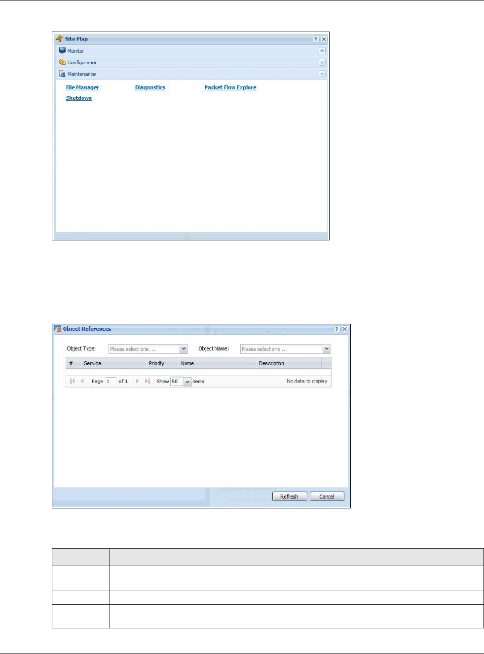
Chapter 1 Introduction
USG20(W)-VPN Series User’s Guide
26
Figure 10 Site Map
Object Reference
Click Object Reference to open the Object Reference screen. Select the type of object and the
individual object and click Refresh to show which configuration settings reference the object.
Figure 11 Object Reference
The fields vary with the type of object. This table describes labels that can appear in this screen.
Table 5 Object References
LABEL DESCRIPTION
Object Name This identifies the object for which the configuration settings that use it are displayed. Click the
object’s name to display the object’s configuration screen in the main window.
# This field is a sequential value, and it is not associated with any entry.
Service This is the type of setting that references the selected object. Click a service’s name to display
the service’s configuration screen in the main window.
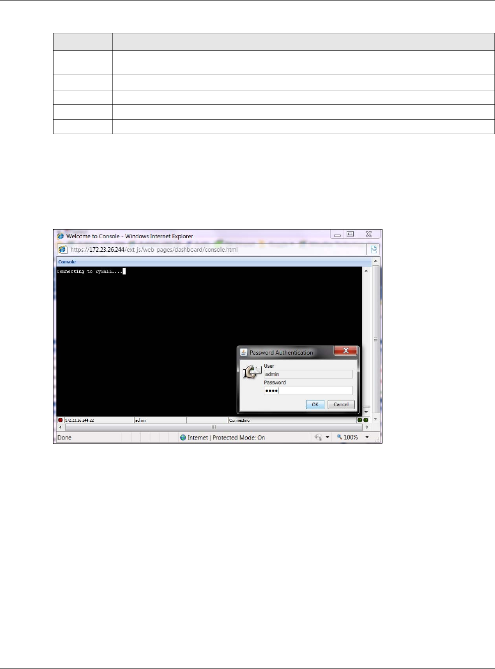
Chapter 1 Introduction
USG20(W)-VPN Series User’s Guide
27
Console
Click Console to open a Java-based console window from which you can run CLI commands. You
will be prompted to enter your user name and password. See the Command Reference Guide for
information about the commands.
Figure 12 Console Window
CLI Messages
Click CLI to look at the CLI commands sent by the Web Configurator. Open the pop-up window and
then click some menus in the web configurator to display the corresponding commands.
Priority If it is applicable, this field lists the referencing configuration item’s position in its list,
otherwise N/A displays.
Name This field identifies the configuration item that references the object.
Description If the referencing configuration item has a description configured, it displays here.
Refresh Click this to update the information in this screen.
Cancel Click Cancel to close the screen.
Table 5 Object References (continued)
LABEL DESCRIPTION
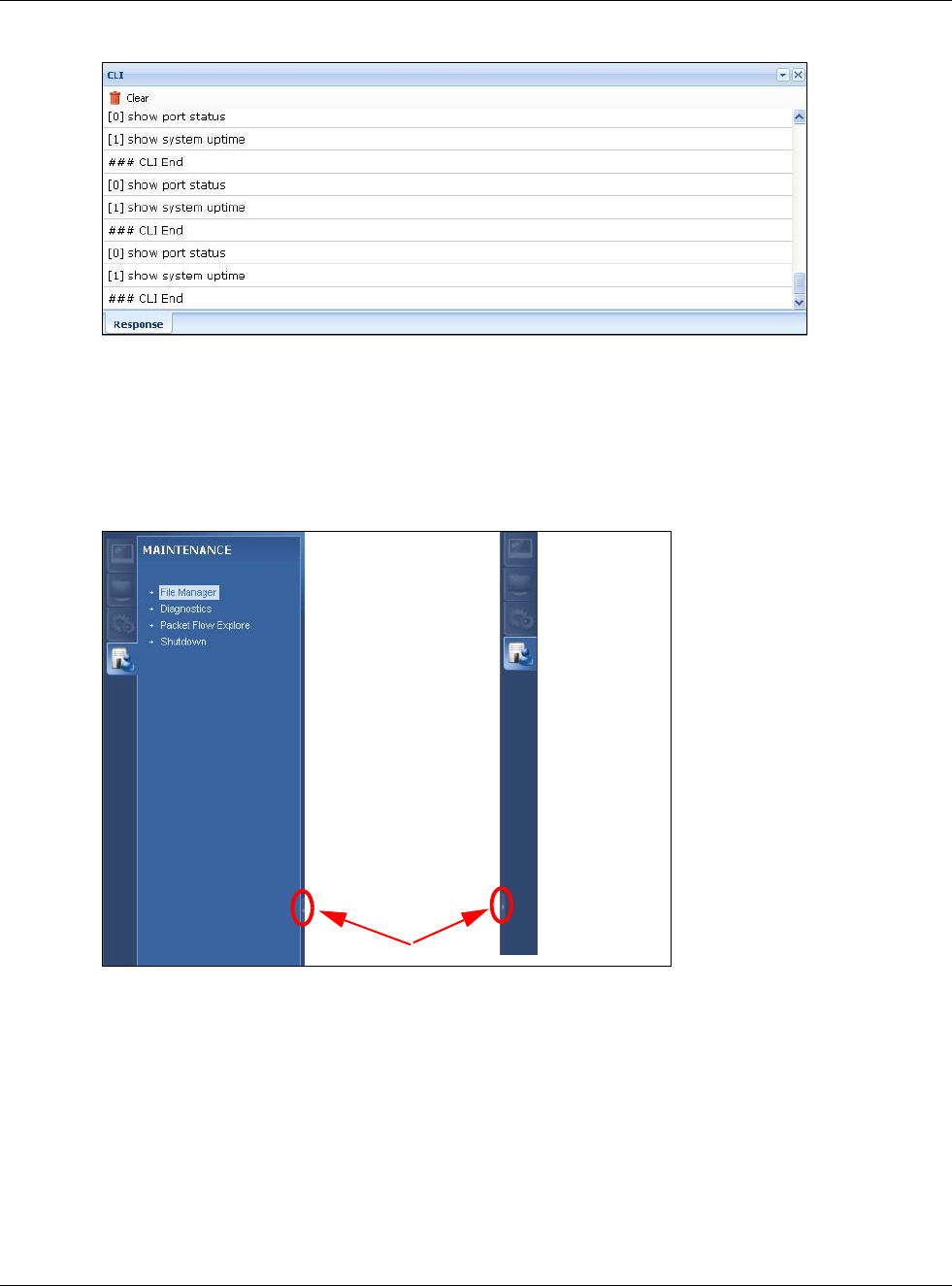
Chapter 1 Introduction
USG20(W)-VPN Series User’s Guide
28
Figure 13 CLI Messages
1.3.3 Navigation Panel
Use the navigation panel menu items to open status and configuration screens. Click the arrow in
the middle of the right edge of the navigation panel to hide the panel or drag to resize it. The
following sections introduce the USG’s navigation panel menus and their screens.
Figure 14 Navigation Panel
Dashboard
The dashboard displays general device information, system status, system resource usage, licensed
service status, and interface status in widgets that you can re-arrange to suit your needs. See the
Web Help for details on the dashboard.

Chapter 1 Introduction
USG20(W)-VPN Series User’s Guide
29
Monitor Menu
The monitor menu screens display status and statistics information.
Table 6 Monitor Menu Screens Summary
FOLDER OR LINK TAB FUNCTION
System Status
Port Statistics Port
Statistics
Displays packet statistics for each physical port.
Interface
Status Interface
Summary
Displays general interface information and packet statistics.
Traffic
Statistics Traffic
Statistics
Collect and display traffic statistics.
Session
Monitor Session
Monitor
Displays the status of all current sessions.
IGMP Statistics IGMP
Statistics
Collect and display IGMP statistics.
DDNS Status DDNS
Status
Displays the status of the USG’s DDNS domain names.
IP/MAC Binding IP/MAC
Binding
Lists the devices that have received an IP address from USG interfaces
using IP/MAC binding.
Login Users Login Users Lists the users currently logged into the USG.
Cellular Status Cellular
Status
Displays details about the USG’s mobile broadband connection status.
UPnP Port
Status Port
Statistics
Displays details about UPnP connections going through the USG.
USB Storage Storage
Information
Displays details about USB device connected to the USG.
Ethernet
Neighbor Ethernet
Neighbor
View and manage the USG’s neighboring devices via Smart Connect
(Layer Link Discovery Protocol (LLDP)). Use the ZyXEL One Network
(ZON) utility to view and manage the USG’s neighboring devices via the
ZyXEL Discovery Protocol (ZDP).
Wireless
AP Information WLAN
Setting
Edit wireless AP information, remove APs, and reboot them.
DCS Configure dynamic wireless channel selection.
VPN Monitor
IPSec IPSec Displays and manages the active IPSec SAs.
SSL SSL Lists users currently logged into the VPN SSL client portal. You can also
log out individual users and delete related session information.
L2TP over
IPSec Session
Monitor
Displays details about current L2TP sessions.
UTM Statistics
Content Filter Report Collect and display content filter statistics
Anti-Spam Report Collect and display spam statistics.
Status Displays how many mail sessions the USG is currently checking and
DNSBL (Domain Name Service-based spam Black List) statistics.
Log View Log Lists log entries.
View AP Log Lists AP log entries.

Chapter 1 Introduction
USG20(W)-VPN Series User’s Guide
30
Configuration Menu
Use the configuration menu screens to configure the USG’s features.
Table 7 Configuration Menu Screens Summary
FOLDER OR LINK TAB FUNCTION
Quick Setup Quickly configure WAN interfaces or VPN connections.
Licensing
Registration Registration Register the device and activate trial services.
Service View the licensed service status and upgrade licensed services.
Wireless
AP Management WLAN Setting Configuration the USG’s general wireless settings.
DCS Configure dynamic wireless channel selection.
Network
Interface Port Role Use this screen to set the USG’s flexible ports such as LAN, OPT,
WLAN, or DMZ.
Ethernet Manage Ethernet interfaces and virtual Ethernet interfaces.
PPP Create and manage PPPoE and PPTP interfaces.
Cellular Configure a cellular Internet connection for an installed mobile
broadband card.
Tunnel Configure tunneling between IPv4 and IPv6 networks.
VLAN Create and manage VLAN interfaces and virtual VLAN interfaces.
Bridge Create and manage bridges and virtual bridge interfaces.
Trunk Create and manage trunks (groups of interfaces) for load
balancing.
Routing Policy Route Create and manage routing policies.
Static Route Create and manage IP static routing information.
RIP Configure device-level RIP settings.
OSPF Configure device-level OSPF settings, including areas and virtual
links.
DDNS DDNS Define and manage the USG’s DDNS domain names.
NAT NAT Set up and manage port forwarding rules.
HTTP Redirect HTTP Redirect Set up and manage HTTP redirection rules.
ALG ALG Configure SIP, H.323, and FTP pass-through settings.
UPnP UPnP Configure interfaces that allow UPnP and NAT-PMP connections.
IP/MAC
Binding Summary Configure IP to MAC address bindings for devices connected to
each supported interface.
Exempt List Configure ranges of IP addresses to which the USG does not apply
IP/MAC binding.
Layer 2
Isolation General Enable layer-2 isolation on the USG and the internal interface(s).
White List Enable and configure the white list.
DNS Inbound
LB DNS Load
Balancing
Configure DNS Load Balancing.
Web
Authentication
Web Authentication Define a web portal and exempt services from authentication.
SSO Configure the USG to work with a Single Sign On agent.
Security Policy

Chapter 1 Introduction
USG20(W)-VPN Series User’s Guide
31
Policy Control Policy Create and manage level-3 traffic rules and apply UTM profiles.
Session
Control Session Control Limit the number of concurrent client NAT/security policy sessions.
VPN
IPSec VPN VPN Connection Configure IPSec tunnels.
VPN Gateway Configure IKE tunnels.
Concentrator Combine IPSec VPN connections into a single secure network
Configuration
Provisioning
Set who can retrieve VPN rule settings from the USG using the USG
IPSec VPN Client.
SSL VPN Access Privilege Configure SSL VPN access rights for users and groups.
Global Setting Configure the USG’s SSL VPN settings that apply to all connections.
SecuExtender Check for the latest version of the SecuExtender VPN client.
L2TP VPN L2TP VPN Configure L2TP over IPSec tunnels.
BWM BWM Enable and configure bandwidth management rules.
UTM Profile
Content Filter Profile Create and manage the detailed filtering rules for content filtering
profiles and then apply to a traffic flow using a security policy.
Trusted Web Sites Create a list of allowed web sites that bypass content filtering
policies.
Forbidden Web
Sites
Create a list of web sites to block regardless of content filtering
policies.
Anti-Spam Profile Turn anti-spam on or off and manage anti-spam policies. Create
anti-spam template(s) of settings to apply to a traffic flow using a
security policy.
Mail Scan Configure e-mail scanning details.
Black/White List Set up a black list to identify spam and a white list to identify
legitimate e-mail.
DNSBL Have the USG check e-mail against DNS Black Lists.
Object
Zone Zone Configure zone template(s) used to define various policies.
User/Group User Create and manage users.
Group Create and manage groups of users.
Setting Manage default settings for all users, general settings for user
sessions, and rules to force user authentication.
MAC Address Configure the MAC addresses or OUI (Organizationally Unique
Identifier) of wireless clients for MAC authentication using the local
user database.
AP Profile Radio Create template(s) of radio settings to apply to policies as an
object.
SSID Create template(s) of wireless settings to apply to radio profiles or
policies as an object.
MON Profile MON Profile Create and manage rogue AP monitoring files that can be
associated with different APs.
Address Address Create and manage host, range, and network (subnet) addresses.
Address Group Create and manage groups of addresseto apply to policies as a
single objects.
Table 7 Configuration Menu Screens Summary (continued)
FOLDER OR LINK TAB FUNCTION

Chapter 1 Introduction
USG20(W)-VPN Series User’s Guide
32
Service Service Create and manage TCP and UDP services.
Service Group Create and manage groups of services to apply to policies as a
single object.
Schedule Schedule Create one-time and recurring schedules.
Schedule Group Create and manage groups of schedules to apply to policies as a
single object.
AAA Server Active Directory Configure the Active Directory settings.
LDAP Configure the LDAP settings.
RADIUS Configure the RADIUS settings.
Auth. Method Authentication
Method
Create and manage ways of authenticating users.
Certificate My Certificates Create and manage the USG’s certificates.
Trusted Certificates Import and manage certificates from trusted sources.
ISP Account ISP Account Create and manage ISP account information for PPPoE/PPTP
interfaces.
SSL Application SSL Application Create SSL web application or file sharing objects to apply to
policies.
DHCPv6 Request Configure IPv6 DHCP request type and interface information.
Lease Configure IPv6 DHCP lease type and interface information.
System
Host Name Host Name Configure the system and domain name for the USG.
USB Storage Settings Configure the settings for the connected USB devices.
Date/Time Date/Time Configure the current date, time, and time zone in the USG.
Console Speed Console Speed Set the console speed.
DNS DNS Configure the DNS server and address records for the USG.
WWW Service Control Configure HTTP, HTTPS, and general authentication.
Login Page Configure how the login and access user screens look.
SSH SSH Configure SSH server and SSH service settings.
TELNET TELNET Configure telnet server settings for the USG.
FTP FTP Configure FTP server settings.
SNMP SNMP Configure SNMP communities and services.
Auth. Server Auth. Server Configure the USG to act as a RADIUS server.
CloudCNM CloudCNM Enable and configure management of the USG by a Central
Network Management system.
Language Language Select the Web Configurator language.
IPv6 IPv6 Enable IPv6 globally on the USG here.
ZON ZON Use the ZyXEL One Network (ZON) utility to view and manage the
USG’s neighboring devices via the ZyXEL Discovery Protocol (ZDP).
Log & Report
Email Daily
Report Email Daily Report Configure where and how to send daily reports and what reports to
send.
Log Settings Log Settings Configure the system log, e-mail logs, and remote syslog servers.
Table 7 Configuration Menu Screens Summary (continued)
FOLDER OR LINK TAB FUNCTION
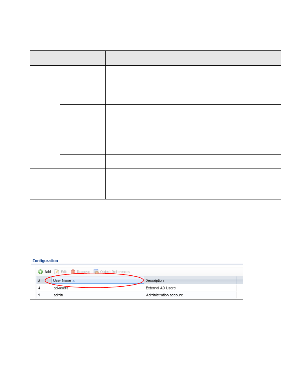
Chapter 1 Introduction
USG20(W)-VPN Series User’s Guide
33
Maintenance Menu
Use the maintenance menu screens to manage configuration and firmware files, run diagnostics,
and reboot or shut down the USG.
1.3.4 Tables and Lists
Web Configurator tables and lists are flexible with several options for how to display their entries.
Click a column heading to sort the table’s entries according to that column’s criteria.
Figure 15 Sorting Table Entries by a Column’s Criteria
Click the down arrow next to a column heading for more options about how to display the entries.
The options available vary depending on the type of fields in the column. Here are some examples
of what you can do:
• Sort in ascending or descending (reverse) alphabetical order
• Select which columns to display
• Group entries by field
• Show entries in groups
• Filter by mathematical operators (<, >, or =) or searching for text
Table 8 Maintenance Menu Screens Summary
FOLDER
OR LINK TAB FUNCTION
File
Manager
Configuration File Manage and upload configuration files for the USG.
Firmware Package View the current firmware version and upload firmware. Reboot with your
choice of firmware.
Shell Script Manage and run shell script files for the USG.
Diagnostics Diagnostic Collect diagnostic information.
Packet Capture Capture packets for analysis.
Core Dump Connect a USB device to the USG and save the USG operating system kernel
to it here.
System Log Connect a USB device to the USG and archive the USG system logs to it
here.
Network Tool Identify problems with the connections. You can use Ping or TraceRoute to
help you identify problems.
Wireless Frame
Capture
Capture wireless frames from APs for analysis.
Packet
Flow
Explore
Routing Status Check how the USG determines where to route a packet.
SNAT Status View a clear picture on how the USG converts a packet’s source IP address
and check the related settings.
Shutdown Shutdown Turn off the USG.
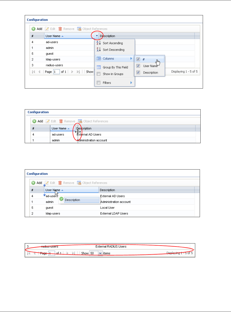
Chapter 1 Introduction
USG20(W)-VPN Series User’s Guide
34
Figure 16 Common Table Column Options
Select a column heading cell’s right border and drag to re-size the column.
Figure 17 Resizing a Table Column
Select a column heading and drag and drop it to change the column order. A green check mark
displays next to the column’s title when you drag the column to a valid new location.
Figure 18 Moving Columns
Use the icons and fields at the bottom of the table to navigate to different pages of entries and
control how many entries display at a time.
Figure 19 Navigating Pages of Table Entries
The tables have icons for working with table entries. You can often use the [Shift] or [Ctrl] key to
select multiple entries to remove, activate, or deactivate.
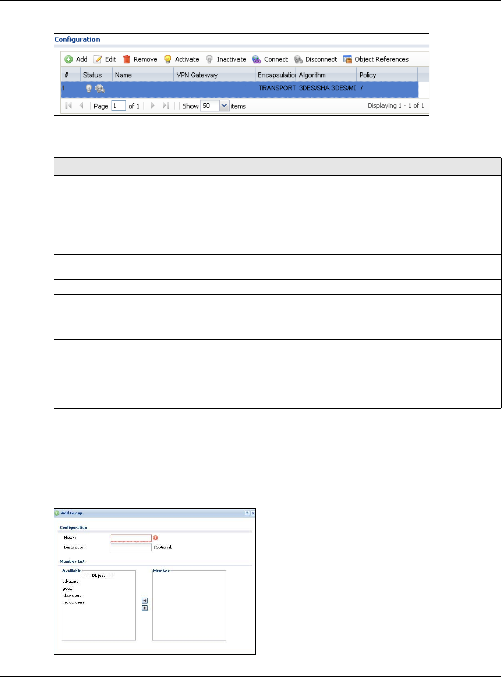
Chapter 1 Introduction
USG20(W)-VPN Series User’s Guide
35
Figure 20 Common Table Icons
Here are descriptions for the most common table icons.
Working with Lists
When a list of available entries displays next to a list of selected entries, you can often just double-
click an entry to move it from one list to the other. In some lists you can also use the [Shift] or
[Ctrl] key to select multiple entries, and then use the arrow button to move them to the other list.
Figure 21 Working with Lists
Table 9 Common Table Icons
LABEL DESCRIPTION
Add Click this to create a new entry. For features where the entry’s position in the numbered list is
important (features where the USG applies the table’s entries in order like the security policy for
example), you can select an entry and click Add to create a new entry after the selected entry.
Edit Double-click an entry or select it and click Edit to open a screen where you can modify the
entry’s settings. In some tables you can just click a table entry and edit it directly in the table.
For those types of tables small red triangles display for table entries with changes that you have
not yet applied.
Remove To remove an entry, select it and click Remove. The USG confirms you want to remove it before
doing so.
Activate To turn on an entry, select it and click Activate.
Inactivate To turn off an entry, select it and click Inactivate.
Connect To connect an entry, select it and click Connect.
Disconnect To disconnect an entry, select it and click Disconnect.
Object
References
Select an entry and click Object References to check which settings use the entry.
Move To change an entry’s position in a numbered list, select it and click Move to display a field to
type a number for where you want to put that entry and press [ENTER] to move the entry to the
number that you typed. For example, if you type 6, the entry you are moving becomes number 6
and the previous entry 6 (if there is one) gets pushed up (or down) one.
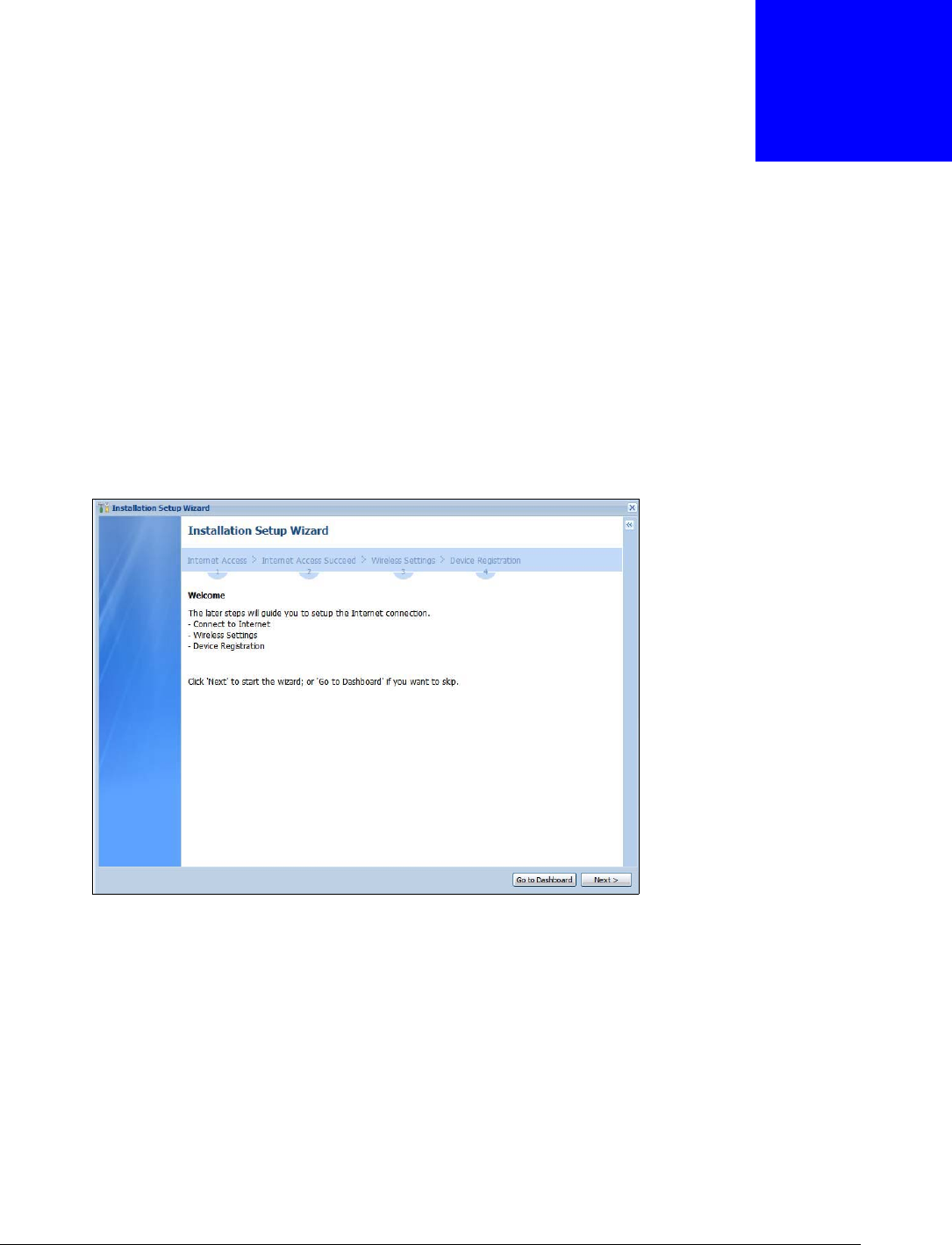
USG20(W)-VPN Series User’s Guide
36
CHAPTER 2
Installation Setup Wizard
2.1 Installation Setup Wizard Screens
When you log into the Web Configurator for the first time or when you reset the USG to its default
configuration, the Installation Setup Wizard screen displays. This wizard helps you configure
Internet connection settings and activate subscription services. This chapter provides information
on configuring the Web Configurator's installation setup wizard. See the feature-specific chapters in
this User’s Guide for background information.
Figure 22 Installation Setup Wizard
• Click the double arrow in the upper right corner to display or hide the help.
• Click Go to Dashboard to skip the installation setup wizard or click Next to start configuring for
Internet access.
2.1.1 Internet Access Setup - WAN Interface
Use this screen to set how many WAN interfaces to configure and the first WAN interface’s type of
encapsulation and method of IP address assignment.
The screens vary depending on the encapsulation type. Refer to information provided by your ISP
to know what to enter in each field. Leave a field blank if you don’t have that information.
Note: Enter the Internet access information exactly as your ISP gave it to you.
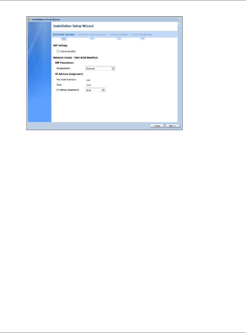
Chapter 2 Installation Setup Wizard
USG20(W)-VPN Series User’s Guide
37
Figure 23 Internet Access: Step 1
•I have two ISPs: Select this option to configure two Internet connections. Leave it cleared to
configure just one. This option appears when you are configuring the first WAN interface.
•Encapsulation: Choose the Ethernet option when the WAN port is used as a regular Ethernet.
Otherwise, choose PPPoE or PPTP for a dial-up connection according to the information from
your ISP.
•WAN Interface: This is the interface you are configuring for Internet access.
•Zone: This is the security zone to which this interface and Internet connection belong.
•IP Address Assignment: Select Auto if your ISP did not assign you a fixed IP address.
Select Static if the ISP assigned a fixed IP address.
2.1.2 Internet Access: Ethernet
This screen is read-only if you set the previous screen’s IP Address Assignment field to Auto. If
you set the previous screen’s IP Address Assignment field to Static, use this screen to configure
your IP address settings.
Note: Enter the Internet access information exactly as given to you by your ISP or
network administrator.
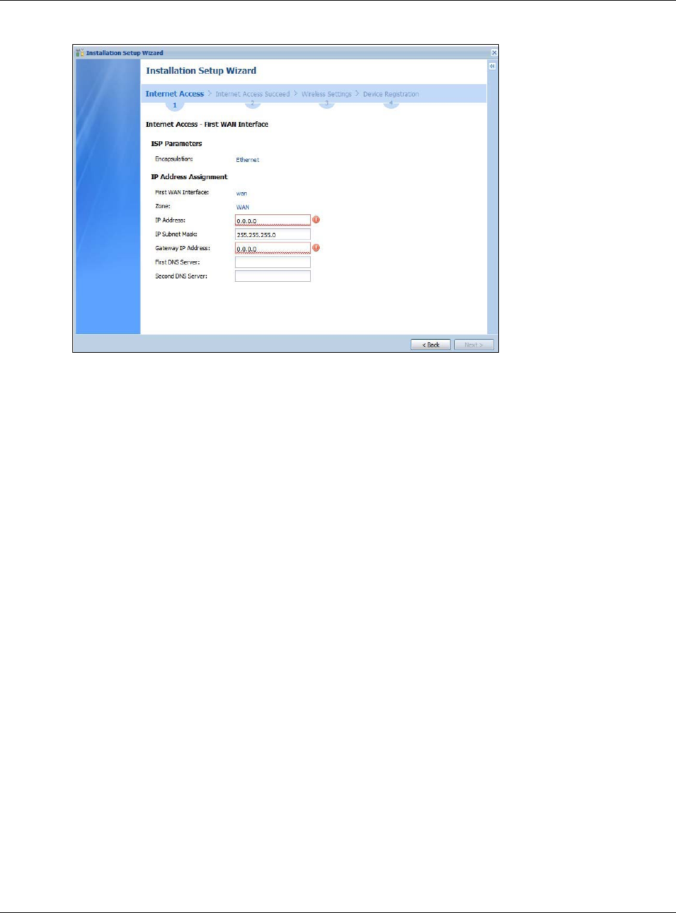
Chapter 2 Installation Setup Wizard
USG20(W)-VPN Series User’s Guide
38
Figure 24 Internet Access: Ethernet Encapsulation
•Encapsulation: This displays the type of Internet connection you are configuring.
•First WAN Interface: This is the number of the interface that will connect with your ISP.
•Zone: This is the security zone to which this interface and Internet connection will belong.
•IP Address: Enter your (static) public IP address. Auto displays if you selected Auto as the IP
Address Assignment in the previous screen.
The following fields display if you selected static IP address assignment.
•IP Subnet Mask: Enter the subnet mask for this WAN connection's IP address.
•Gateway IP Address: Enter the IP address of the router through which this WAN connection
will send traffic (the default gateway).
•First / Second DNS Server: These fields display if you selected static IP address assignment.
The Domain Name System (DNS) maps a domain name to an IP address and vice versa. Enter a
DNS server's IP address(es). The DNS server is extremely important because without it, you
must know the IP address of a computer before you can access it. The USG uses these (in the
order you specify here) to resolve domain names for VPN, DDNS and the time server. Leave the
field as 0.0.0.0 if you do not want to configure DNS servers.
2.1.3 Internet Access: PPPoE
Note: Enter the Internet access information exactly as given to you by your ISP.
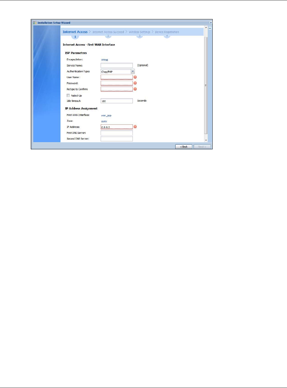
Chapter 2 Installation Setup Wizard
USG20(W)-VPN Series User’s Guide
39
Figure 25 Internet Access: PPPoE Encapsulation
2.1.3.1 ISP Parameters
• Type the PPPoE Service Name from your service provider. PPPoE uses a service name to identify
and reach the PPPoE server. You can use alphanumeric and -_@$./ characters, and it can be up
to 64 characters long.
•Authentication Type - Select an authentication protocol for outgoing connection requests.
Options are:
•CHAP/PAP - Your USG accepts either CHAP or PAP when requested by the remote node.
•CHAP - Your USG accepts CHAP only.
•PAP - Your USG accepts PAP only.
•MSCHAP - Your USG accepts MSCHAP only.
•MSCHAP-V2 - Your USG accepts MSCHAP-V2 only.
•Type the User Name given to you by your ISP. You can use alphanumeric and -_@$./ characters,
and it can be up to 31 characters long.
•Type the Password associated with the user name. Use up to 64 ASCII characters except the []
and ?. This field can be blank.
•Select Nailed-Up if you do not want the connection to time out. Otherwise, type the Idle
Timeout in seconds that elapses before the router automatically disconnects from the PPPoE
server.
2.1.3.2 WAN IP Address Assignments
•WAN Interface: This is the name of the interface that will connect with your ISP.
•Zone: This is the security zone to which this interface and Internet connection will belong.
•IP Address: Enter your (static) public IP address. Auto displays if you selected Auto as the IP
Address Assignment in the previous screen.
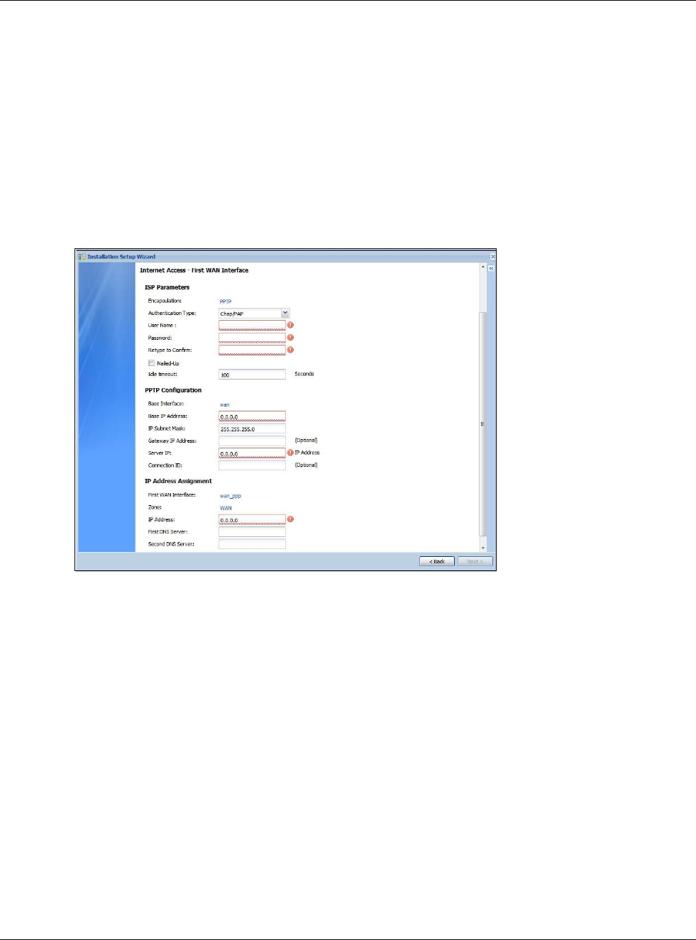
Chapter 2 Installation Setup Wizard
USG20(W)-VPN Series User’s Guide
40
•First / Second DNS Server: These fields display if you selected static IP address assignment.
The Domain Name System (DNS) maps a domain name to an IP address and vice versa. Enter a
DNS server's IP address(es). The DNS server is extremely important because without it, you
must know the IP address of a computer before you can access it. The USG uses these (in the
order you specify here) to resolve domain names for VPN, DDNS and the time server. Leave the
field as 0.0.0.0 if you do not want to configure DNS servers. If you do not configure a DNS server,
you must know the IP address of a machine in order to access it.
2.1.4 Internet Access: PPTP
Note: Enter the Internet access information exactly as given to you by your ISP.
Figure 26 Internet Access: PPTP Encapsulation
2.1.4.1 ISP Parameters
•Authentication Type - Select an authentication protocol for outgoing calls. Options are:
•CHAP/PAP - Your USG accepts either CHAP or PAP when requested by the remote node.
•CHAP - Your USG accepts CHAP only.
•PAP - Your USG accepts PAP only.
•MSCHAP - Your USG accepts MSCHAP only.
•MSCHAP-V2 - Your USG accepts MSCHAP-V2 only.
•Type the User Name given to you by your ISP. You can use alphanumeric and -_@$./ characters,
and it can be up to 31 characters long.
•Type the Password associated with the user name. Use up to 64 ASCII characters except the []
and ?. This field can be blank. Re-type your password in the next field to confirm it.
•Select Nailed-Up if you do not want the connection to time out. Otherwise, type the Idle
Timeout in seconds that elapses before the router automatically disconnects from the PPTP
server.
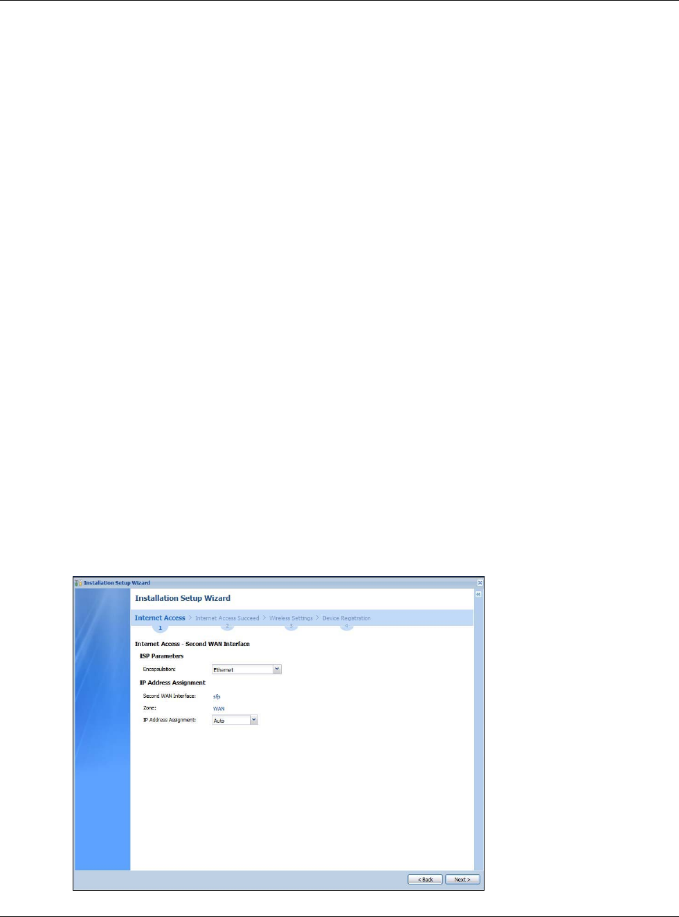
Chapter 2 Installation Setup Wizard
USG20(W)-VPN Series User’s Guide
41
2.1.4.2 PPTP Configuration
•Base Interface: This identifies the Ethernet interface you configure to connect with a modem or
router.
•Type a Base IP Address (static) assigned to you by your ISP.
• Type the IP Subnet Mask assigned to you by your ISP (if given).
•Server IP: Type the IP address of the PPTP server.
•Type a Connection ID or connection name. It must follow the “c:id” and “n:name” format. For
example, C:12 or N:My ISP. This field is optional and depends on the requirements of your
broadband modem or router. You can use alphanumeric and -_: characters, and it can be up to
31 characters long.
2.1.4.3 WAN IP Address Assignments
•First WAN Interface: This is the connection type on the interface you are configuring to
connect with your ISP.
•Zone This is the security zone to which this interface and Internet connection will belong.
•IP Address: Enter your (static) public IP address. Auto displays if you selected Auto as the IP
Address Assignment in the previous screen.
•First / Second DNS Server: These fields display if you selected static IP address assignment.
The Domain Name System (DNS) maps a domain name to an IP address and vice versa. Enter a
DNS server's IP address(es). The DNS server is extremely important because without it, you
must know the IP address of a computer before you can access it. The USG uses these (in the
order you specify here) to resolve domain names for VPN, DDNS and the time server. Leave the
field as 0.0.0.0 if you do not want to configure DNS servers.
2.1.5 Internet Access Setup - Second WAN Interface
If you selected I have two ISPs, after you configure the First WAN Interface, you can configure
the Second WAN Interface. The screens for configuring the second WAN interface are similar to
the first (see Section 2.1.1 on page 36).
Figure 27 Internet Access: Step 3: Second WAN Interface
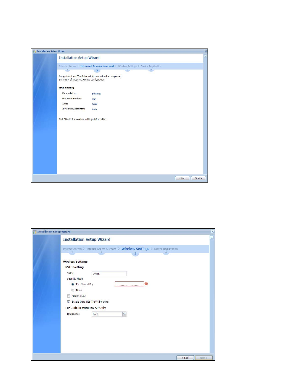
Chapter 2 Installation Setup Wizard
USG20(W)-VPN Series User’s Guide
42
2.1.6 Internet Access Succeed
This screen shows your Internet access settings that have been applied successfully.
Figure 28 Internet Access Succeed
2.1.7 Wireless Settings: SSID & Security
Configure SSID and wireless security in this screen.
Figure 29 Wireless Settings: SSID & Security
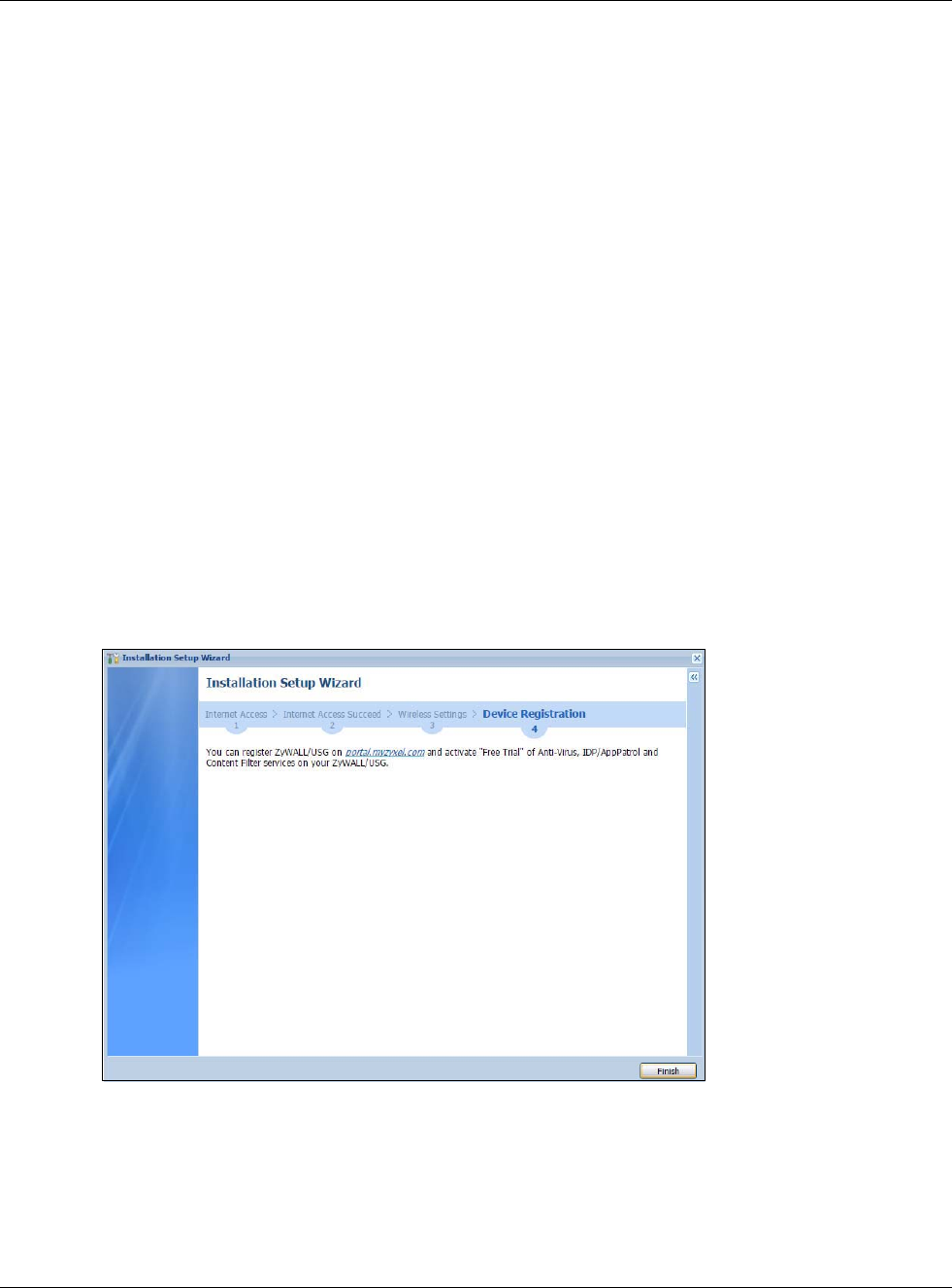
Chapter 2 Installation Setup Wizard
USG20(W)-VPN Series User’s Guide
43
SSID Setting
•SSID - Enter a descriptive name of up to 32 printable characters for the wireless LAN.
•Security Mode - Select Pre-Shared Key to add security on this wireless network. Otherwise,
select None to allow any wireless client to associate this network without authentication.
•Pre-Shared Key - Enter a pre-shared key of between 8 and 63 case-sensitive ASCII characters
(including spaces and symbols) or 64 hexadecimal characters.
•Hidden SSID - Select this option if you want to hide the SSID in the outgoing beacon frame. A
wireless client then cannot obtain the SSID through scanning using a site survey tool.
•Enable Intra-BSS Traffic Blocking - Select this option if you want to prevent crossover traffic
from within the same SSID. Wireless clients can still access the wired network but cannot
communicate with each other.
For Built-in Wireless AP Only
•Bridged to: USGs with W in the model name have a built-in AP. Select an interface to bridge
with the built-in AP wireless network. Devices connected to this interface will then be in the same
broadcast domain as devices in the AP wireless network.
2.1.8 Internet Access - Device Registration
Click the link in this screen to register your device at portal.myzyxel.com.
Note: The USG must be connected to the Internet in order to register.
Figure 30 Internet Access: Device Registration
You will need the USG’s serial number and LAN MAC address to register it if you have not already
done so. Use the Configuration > Licensing > Registration > Service screen to update your
service subscription status.
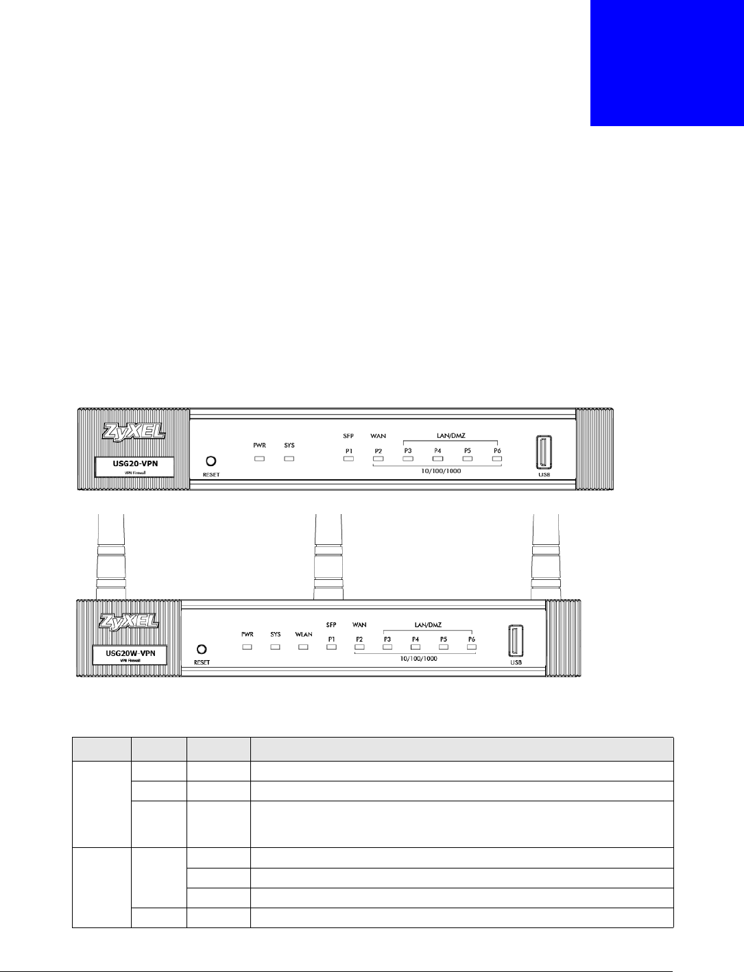
USG20(W)-VPN Series User’s Guide
44
CHAPTER 3
Hardware, Interfaces and Zones
3.1 Hardware Overview
USG20-VPN and USG20W-VPN have different housings.
3.1.1 Front Panels
The LED indicators are located on the front panel.
Figure 31 USG20-VPN Front Panel
Figure 32 USG20W-VPN Front Panel
The following table describes the LEDs.
Table 10 LED Descriptions
LED COLOR STATUS DESCRIPTION
PWR Off The USG is turned off.
Green On The USG is turned on.
Red On There is a hardware component failure. Shut down the device, wait for a few
minutes and then restart the device (see Section 3.1.3 on page 46). If the
LED turns red again, then please contact your vendor.
SYS Green Off The USG is not ready or has failed.
On The USG is ready and running.
Blinking The USG is booting.
Red On The USG had an error or has failed.
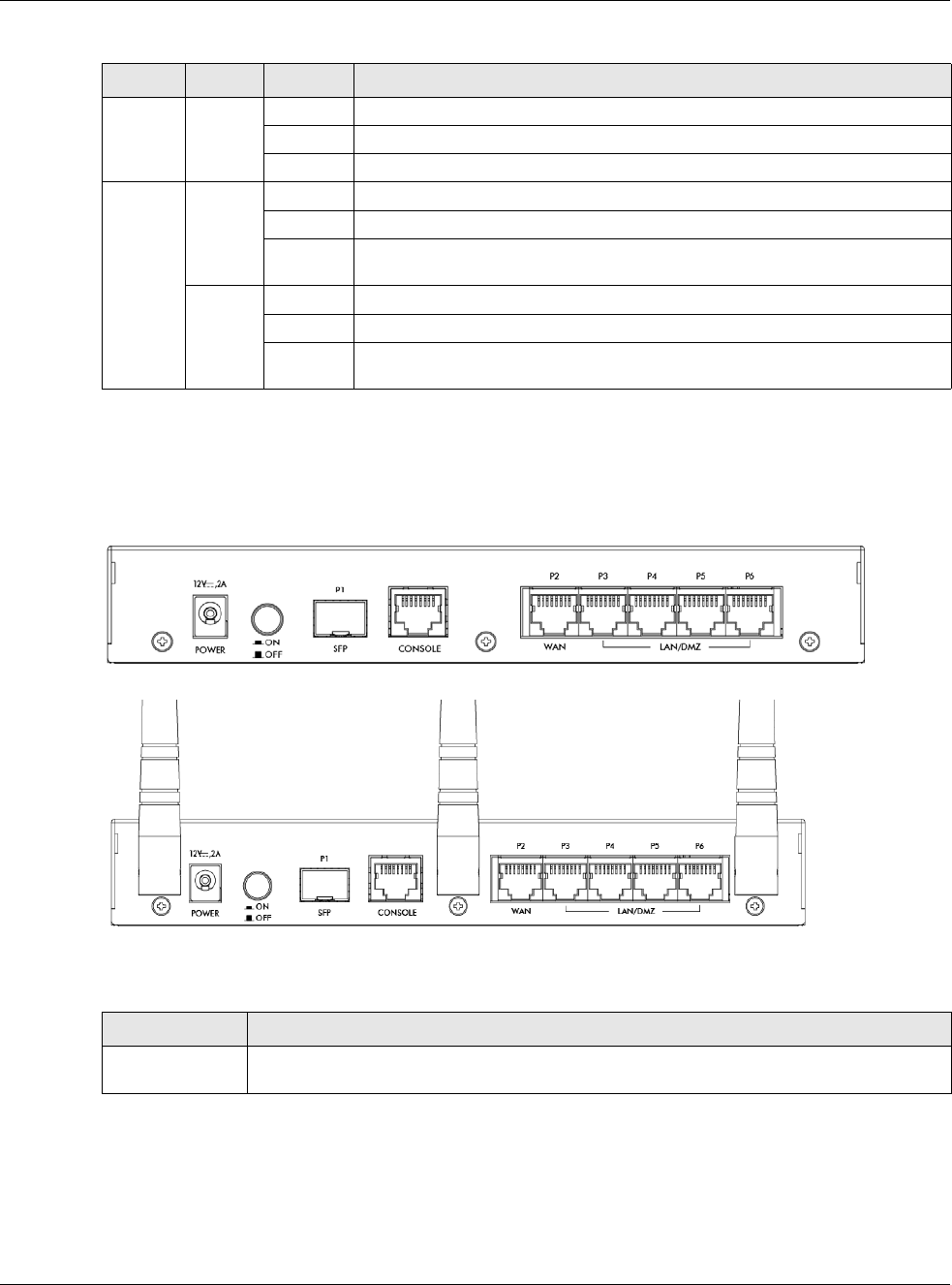
Chapter 3 Hardware, Interfaces and Zones
USG20(W)-VPN Series User’s Guide
45
3.1.2 Rear Panels
The connection ports are located on the rear panel.
Figure 33 USG20-VPN Rear Panel
Figure 34 USG20W-VPN Rear Panel
The following table describes the items on the rear panel
WLAN Green Off The built-in wireless LAN card is not ready or has failed.
On The built-in wireless LAN card is ready.
Blinking The built-in wireless LAN card is sending or receiving packets.
P1, P2... Green Off There is no traffic on this port.
On This port has a successful 10/100 Mbps connection.
Blinking The USG is sending or receiving packets on this port with a 10/100 Mbps
connection.
Yellow Off There is no connection on this port.
On This port has a successful 1000 Mbps connection.
Blinking The device is sending or receiving packets on this port with a 1000 Mbps
connection.
Table 10 LED Descriptions (continued)
LED COLOR STATUS DESCRIPTION
Table 11 Rear Panel Items
LABEL DESCRIPTION
Power Use the included power cord to connect the power socket to a power outlet. Turn the power
switch on if your USG has a power switch.
Chapter 3 Hardware, Interfaces and Zones
USG20(W)-VPN Series User’s Guide
46
Note: Use an 8-wire Ethernet cable to run your Gigabit Ethernet connection at 1000
Mbps. Using a 4-wire Ethernet cable limits your connection to 100 Mbps. Note that
the connection speed also depends on what the Ethernet device at the other end
can support.
3.1.3 Wall-mounting
Both USG20-VPN and USG20W-VPN can be mounted on a wall.
1Drill two holes 3 mm ~ 4 mm (0.12" ~ 0.16") wide, 20 mm ~ 30 mm (0.79” ~ 1.18”) deep and 150
mm apart, into a wall. Place two screw anchors in the holes.
2Screw two screws with 6 mm ~ 8 mm (0.24" ~ 0.31") wide heads into the screw anchors. Do not
screw the screws all the way in to the wall; leave a small gap between the head of the screw and
the wall.
The gap must be big enough for the screw heads to slide into the screw slots and the connection
cables to run down the back of the USG.
Note: Make sure the screws are securely fixed to the wall and strong enough to hold the
weight of the USG with the connection cables.
3Use the holes on the bottom of the USG to hang the USG on the screws.
Wall-mount the USG horizontally. The USG's side panels with ventilation
slots should not be facing up or down as this position is less safe.
WAN/LAN/DMZ/
(Gigabit SFP/
Ethernet Port)
P1- You have to install an SFP (Small Form-factor Pluggable) transceiver and connect fiber
optic cables to it for using a 1Gbps/100Mbps WAN connection.
P2~P6 - Connect an Ethernet cable to the port for using a 1Gbps WAN/LAN/DMZ
connection.
Console You can use the console port to manage the USG using CLI commands. You will be
prompted to enter your user name and password. See the Command Reference Guide for
more information about the CLI.
When configuring using the console port, you need a computer equipped with
communications software configured to the following parameters:
• Speed 115200 bps
•Data Bits 8
• Parity None
•Stop Bit 1
• Flow Control Off
Table 11 Rear Panel Items (continued)
LABEL DESCRIPTION
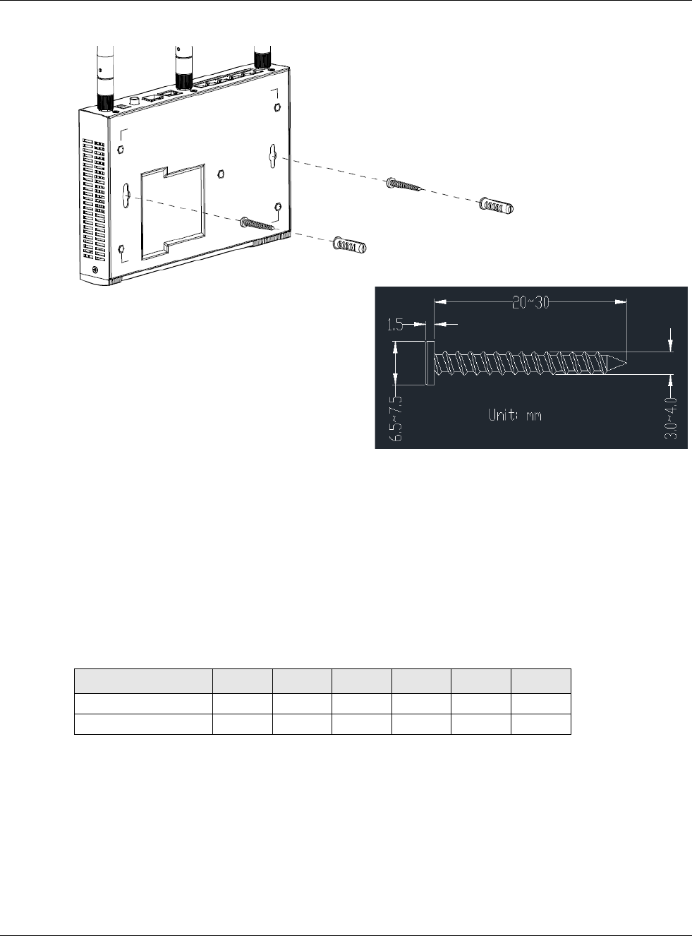
Chapter 3 Hardware, Interfaces and Zones
USG20(W)-VPN Series User’s Guide
47
Figure 35 Wall Mounting
3.2 Default Zones, Interfaces, and Ports
The default configurations for zones, interfaces, and ports are as follows. References to interfaces
may be generic rather than the specific name used in your model. For example, this guide may use
“the WAN interface” rather than “wan1” or “wan2”.
The following table shows the default physical port and interface mapping for each model at the
time of writing.
Screw Specifications
Table 12 Default Physical Port - Interface Mapping
PORT / INTERFACE P1 P2 P3 P4 P5 P6
• USG20-VPN sfp wan lan1 lan1 lan1 lan1
• USG20W-VPN sfp wan lan1 lan1 lan1 lan1
Chapter 3 Hardware, Interfaces and Zones
USG20(W)-VPN Series User’s Guide
48
The following table shows the default interface and zone mapping for each model at the time of
writing.
3.3 Stopping the USG
Always use Maintenance > Shutdown > Shutdown or the shutdown command before you turn
off the USG or remove the power. Not doing so can cause the firmware to become corrupt.
Table 13 Default Zone - Interface Mapping
ZONE / INTERFACE WAN LAN1 LAN2 DMZ
• USG20-VPN WAN
WAN_PPP
SFP
SFP_PPP
LAN1 LAN2 DMZ
• USG20W-VPN WAN
WAN_PPP
SFP
SFP_PPP
LAN1 LAN2 DMZ
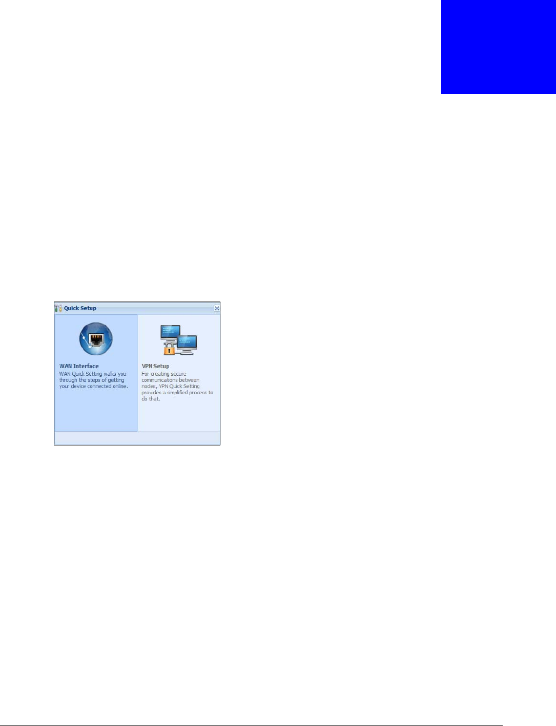
USG20(W)-VPN Series User’s Guide
49
CHAPTER 4
Quick Setup Wizards
4.1 Quick Setup Overview
The Web Configurator's quick setup wizards help you configure Internet and VPN connection
settings. This chapter provides information on configuring the quick setup screens in the Web
Configurator. See the feature-specific chapters in this User’s Guide for background information.
In the Web Configurator, click Configuration > Quick Setup to open the first Quick Setup
screen.
Figure 36 Quick Setup
•WAN Interface
Click this link to open a wizard to set up a WAN (Internet) connection. This wizard creates
matching ISP account settings in the USG if you use PPPoE or PPTP. See Section 4.2 on page 50.
•VPN SETUP
Use VPN Setup to configure a VPN (Virtual Private Network) rule for a secure connection to
another computer or network. Use VPN Settings for Configuration Provisioning to set up a
VPN rule that can be retrieved with the USG IPSec VPN Client. You only need to enter a user
name, password and the IP address of the USG in the IPSec VPN Client to get all VPN settings
automatically from the USG. See Section 4.3 on page 55.Use VPN Settings for L2TP VPN
Settings to configure the L2TP VPN for clients.
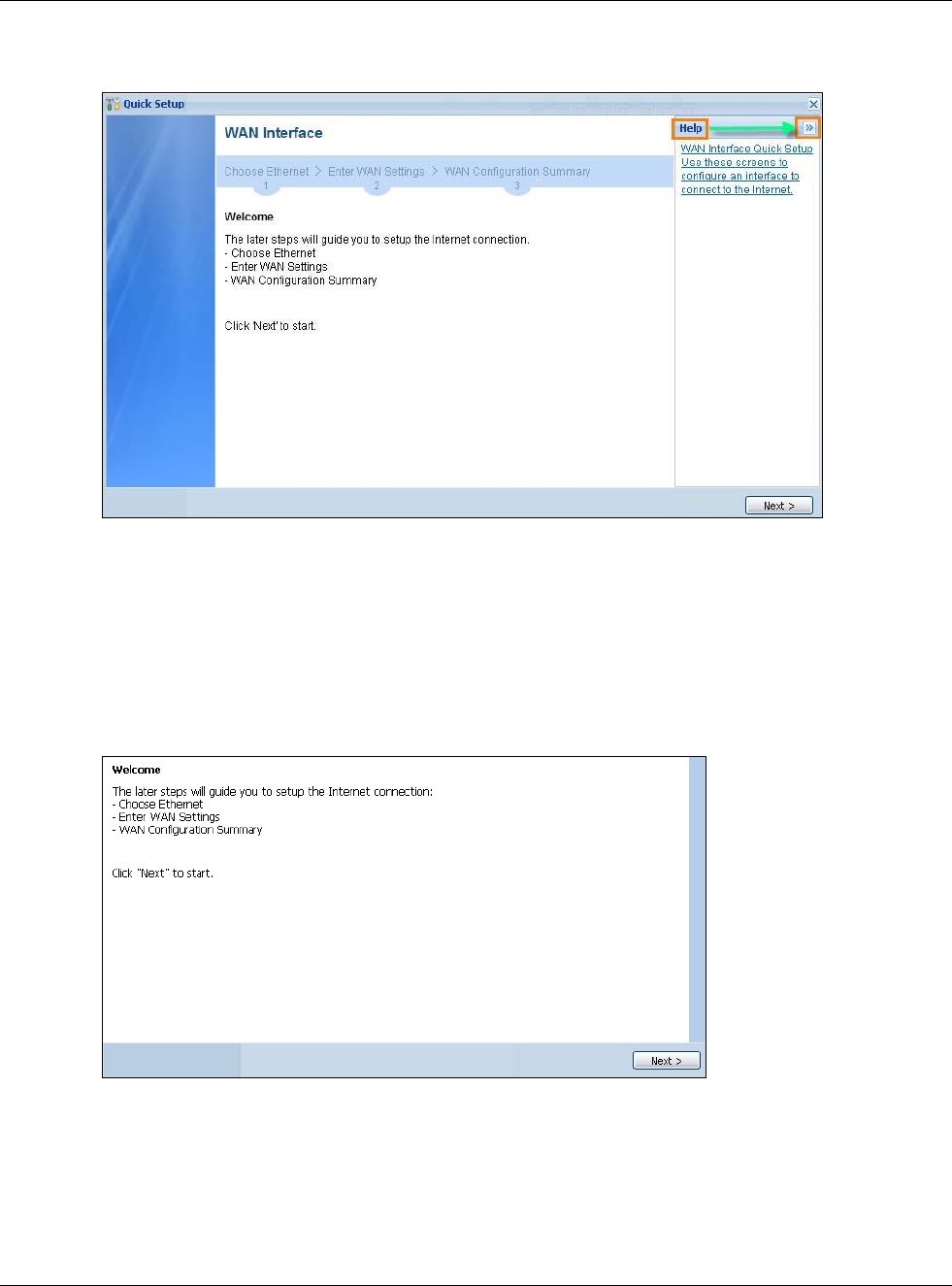
Chapter 4 Quick Setup Wizards
USG20(W)-VPN Series User’s Guide
50
•Wizard Help
If the help does not automatically display when you run the wizard, click teh arrow to display it.
4.2 WAN Interface Quick Setup
Click WAN Interface in the main Quick Setup screen to open the WAN Interface Quick Setup
Wizard Welcome screen. Use these screens to configure an interface to connect to the Internet.
Click Next.
Figure 37 WAN Interface Quick Setup Wizard
4.2.1 Choose an Ethernet Interface
Select the Ethernet interface (names vary by model) that you want to configure for a WAN
connection and click Next.
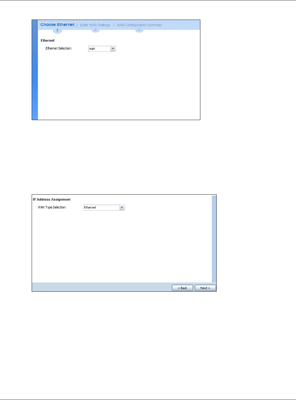
Chapter 4 Quick Setup Wizards
USG20(W)-VPN Series User’s Guide
51
Figure 38 Choose an Ethernet Interface
4.2.2 Select WAN Type
WAN Type Selection: Select the type of encapsulation this connection is to use. Choose Ethernet
when the WAN port is used as a regular Ethernet.
Otherwise, choose PPPoE or PPTP for a dial-up connection according to the information from your
ISP.
Figure 39 WAN Interface Setup: Step 2
The screens vary depending on what encapsulation type you use. Refer to information provided by
your ISP to know what to enter in each field. Leave a field blank if you don’t have that information.
Note: Enter the Internet access information exactly as your ISP gave it to you.
4.2.3 Configure WAN IP Settings
Use this screen to select whether the interface should use a fixed or dynamic IP address.
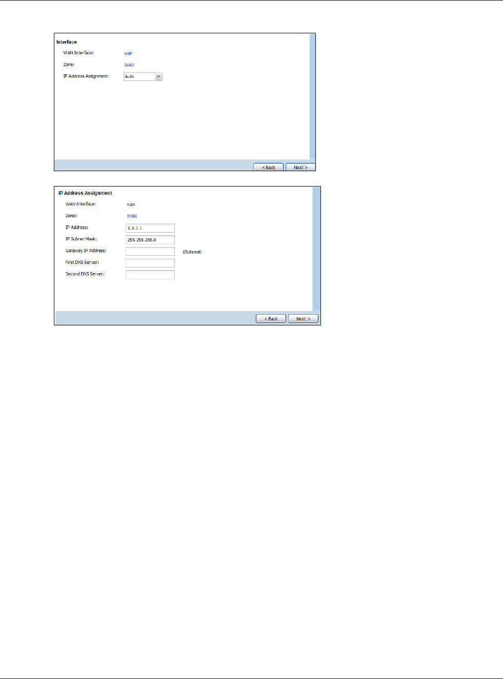
Chapter 4 Quick Setup Wizards
USG20(W)-VPN Series User’s Guide
52
Figure 40 WAN Interface Setup: Step 2 Dynamic IP
Figure 41 WAN Interface Setup: Step 2 Fixed IP
•WAN Interface: This is the interface you are configuring for Internet access.
•Zone: This is the security zone to which this interface and Internet connection belong.
•IP Address Assignment: Select Auto If your ISP did not assign you a fixed IP address.
Select Static if you have a fixed IP address and enter the IP address, subnet mask, gateway IP
address (optional) and DNS server IP address(es).
4.2.4 ISP and WAN and ISP Connection Settings
Use this screen to configure the ISP and WAN interface settings. This screen is read-only if you
select Ethernet and set t the IP Address Assignment to AutoStatic. If you set the IP Address
Assignment to static and/or select PPTP or PPPoE, enter the Internet access information exactly
as your ISP gave it to you.
Note: Enter the Internet access information exactly as your ISP gave it to you.
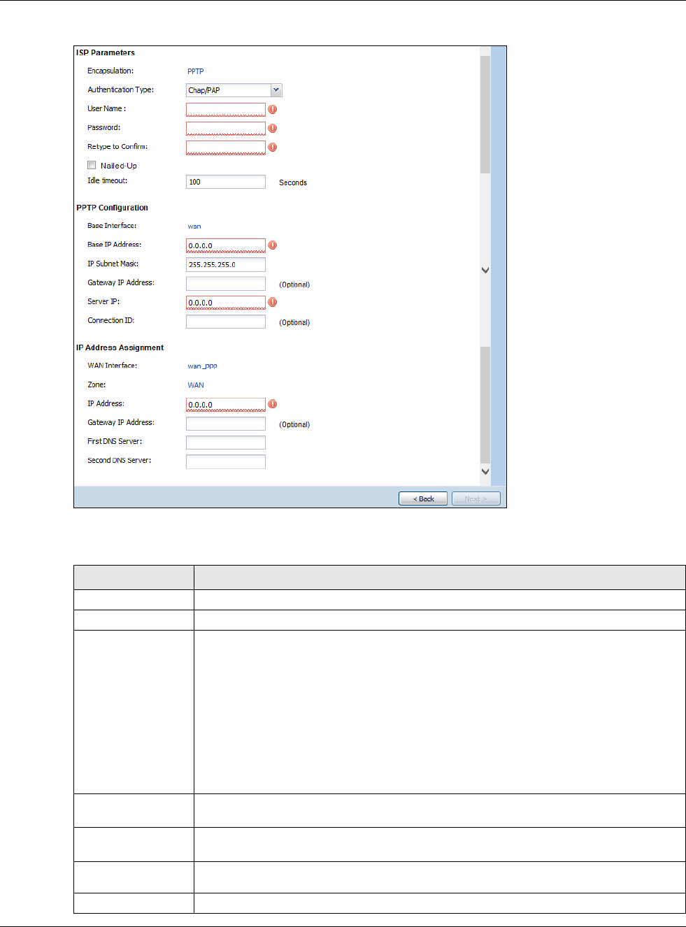
Chapter 4 Quick Setup Wizards
USG20(W)-VPN Series User’s Guide
53
Figure 42 WAN and ISP Connection Settings: (PPTP Shown)
The following table describes the labels in this screen.
Table 14 WAN and ISP Connection Settings
LABEL DESCRIPTION
ISP Parameter This section appears if the interface uses a PPPoE or PPTP Internet connection.
Encapsulation This displays the type of Internet connection you are configuring.
Authentication
Type Use the drop-down list box to select an authentication protocol for outgoing calls.
Options are:
CHAP/PAP - Your USG accepts either CHAP or PAP when requested by this remote
node.
CHAP - Your USG accepts CHAP only.
PAP - Your USG accepts PAP only.
MSCHAP - Your USG accepts MSCHAP only.
MSCHAP-V2 - Your USG accepts MSCHAP-V2 only.
User Name Type the user name given to you by your ISP. You can use alphanumeric and -_@$./
characters, and it can be up to 31 characters long.
Password Type the password associated with the user name above. Use up to 64 ASCII characters
except the [] and ?. This field can be blank.
Retype to
Confirm Type your password again for confirmation.
Nailed-Up Select Nailed-Up if you do not want the connection to time out.

Chapter 4 Quick Setup Wizards
USG20(W)-VPN Series User’s Guide
54
4.2.5 Quick Setup Interface Wizard: Summary
This screen displays the WAN interface’s settings.
Idle Timeout Type the time in seconds that elapses before the router automatically disconnects from
the PPPoE server. 0 means no timeout.
PPTP Configuration This section only appears if the interface uses a PPPoE or PPTP Internet connection.
Base Interface This displays the identity of the Ethernet interface you configure to connect with a
modem or router.
Base IP Address Type the (static) IP address assigned to you by your ISP.
IP Subnet Mask Type the subnet mask assigned to you by your ISP (if given).
Server IP Type the IP address of the PPTP server.
Connection ID Enter the connection ID or connection name in this field. It must follow the "c:id" and
"n:name" format. For example, C:12 or N:My ISP.
This field is optional and depends on the requirements of your DSL modem.
You can use alphanumeric and -_: characters, and it can be up to 31 characters long.
WAN Interface
Setup
WAN Interface This displays the identity of the interface you configure to connect with your ISP.
Zone This field displays to which security zone this interface and Internet connection will
belong.
IP Address This field is read-only when the WAN interface uses a dynamic IP address. If your WAN
interface uses a static IP address, enter it in this field.
First DNS
Server
Second DNS
Server
These fields only display for an interface with a static IP address. Enter the DNS server
IP address(es) in the field(s) to the right.
Leave the field as 0.0.0.0 if you do not want to configure DNS servers. If you do not
configure a DNS server, you must know the IP address of a machine in order to access
it.
DNS (Domain Name System) is for mapping a domain name to its corresponding IP
address and vice versa. The DNS server is extremely important because without it, you
must know the IP address of a computer before you can access it. The USG uses a
system DNS server (in the order you specify here) to resolve domain names for VPN,
DDNS and the time server.
Back Click Back to return to the previous screen.
Next Click Next to continue.
Table 14 WAN and ISP Connection Settings (continued)
LABEL DESCRIPTION
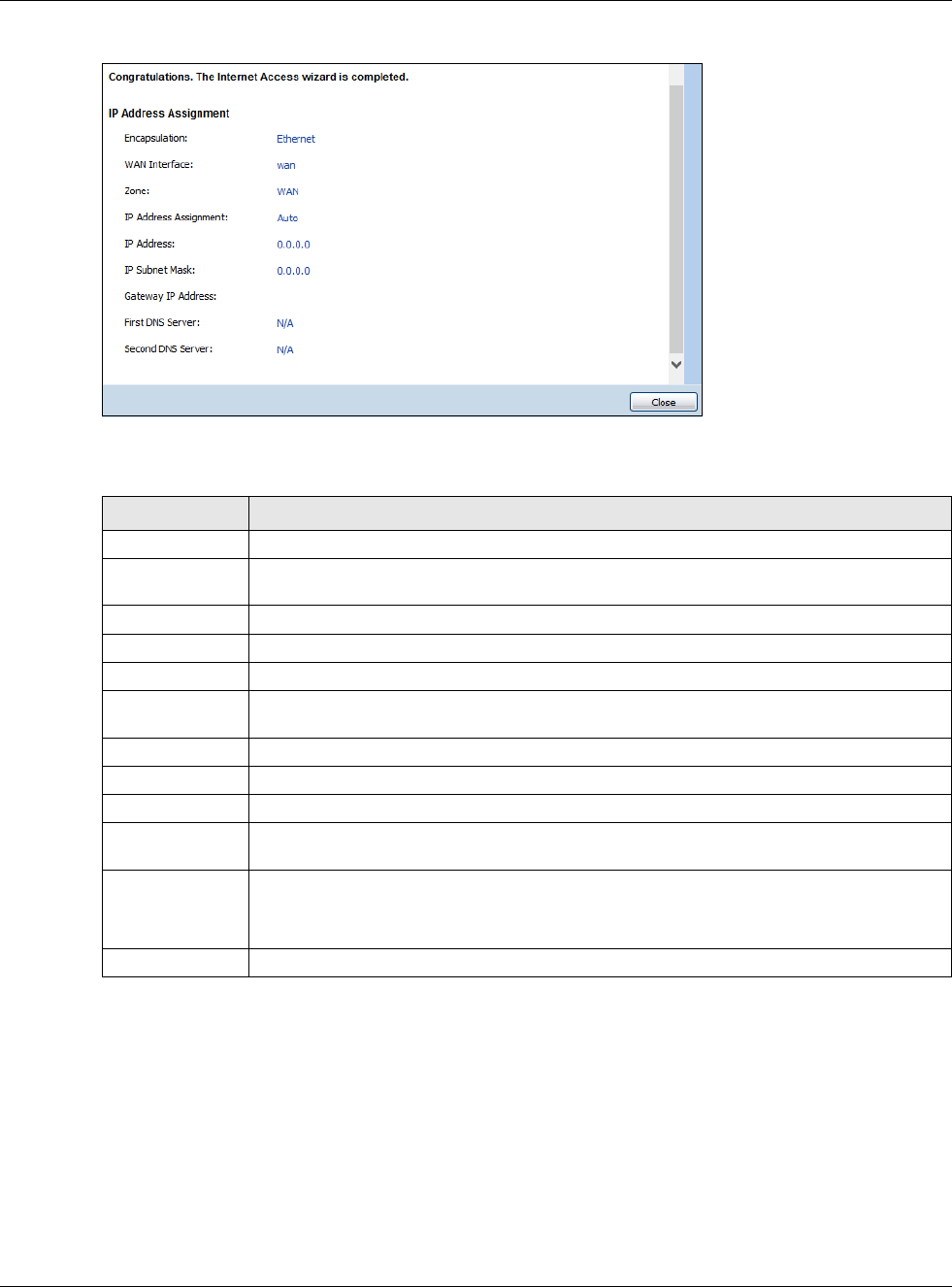
Chapter 4 Quick Setup Wizards
USG20(W)-VPN Series User’s Guide
55
Figure 43 Interface Wizard: Summary WAN (PPTP Shown)
The following table describes the labels in this screen.
4.3 VPN Setup Wizard
Click VPN Setup in the main Quick Setup screen to open the VPN Setup Wizard Welcome screen.
Table 15 Interface Wizard: Summary WAN
LABEL DESCRIPTION
Encapsulation This displays what encapsulation this interface uses to connect to the Internet.
Service Name This field only appears for a PPPoE interface. It displays the PPPoE service name specified
in the ISP account.
Server IP This field only appears for a PPTP interface. It displays the IP address of the PPTP server.
User Name This is the user name given to you by your ISP.
Nailed-Up If No displays the connection will not time out. Yes means the USG uses the idle timeout.
Idle Timeout This is how many seconds the connection can be idle before the router automatically
disconnects from the PPPoE server. 0 means no timeout.
Connection ID If you specified a connection ID, it displays here.
WAN Interface This identifies the interface you configure to connect with your ISP.
Zone This field displays to which security zone this interface and Internet connection will belong.
IP Address
Assignment
This field displays whether the WAN IP address is static or dynamic (Auto).
First DNS Server
Second DNS
Server
If the IP Address Assignment is Static, these fields display the DNS server IP
address(es).
Close Click Close to exit the wizard.
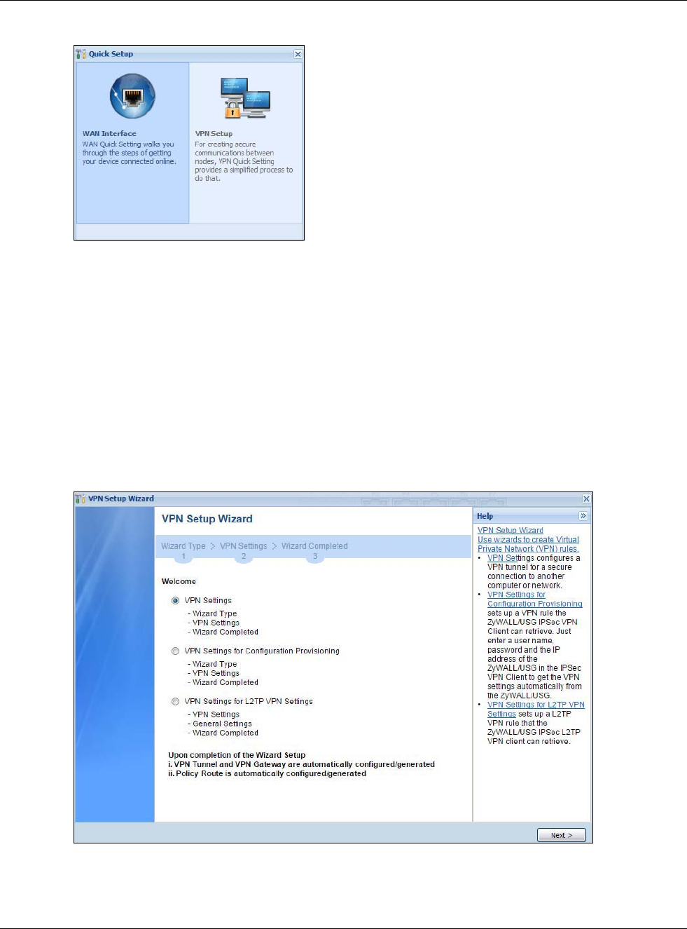
Chapter 4 Quick Setup Wizards
USG20(W)-VPN Series User’s Guide
56
Figure 44 VPN Setup Wizard
4.3.1 Welcome
Use wizards to create Virtual Private Network (VPN) rules. After you complete the wizard, the Phase
1 rule settings appear in the VPN > IPSec VPN > VPN Gateway screen and the Phase 2 rule
settings appear in the VPN > IPSec VPN > VPN Connection screen.
•VPN Settings configures a VPN tunnel for a secure connection to another computer or network.
•VPN Settings for Configuration Provisioning sets up a VPN rule the USG IPSec VPN Client
can retrieve. Just enter a user name, password and the IP address of the USG in the IPSec VPN
Client to get the VPN settings automatically from the USG.
•VPN Settings for L2TP VPN Settings sets up a L2TP VPN rule that the USG IPSec L2TP VPN
client can retrieve.
Figure 45 VPN Setup Wizard Welcome
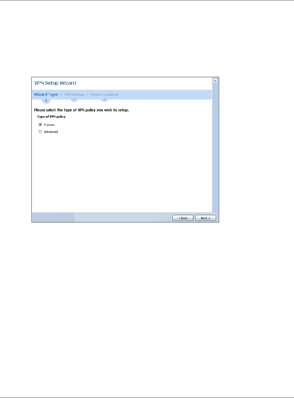
Chapter 4 Quick Setup Wizards
USG20(W)-VPN Series User’s Guide
57
4.3.2 VPN Setup Wizard: Wizard Type
Choose Express to create a VPN rule with the default phase 1 and phase 2 settings to connect to
another ZLD-based USG using a pre-shared key.
Choose Advanced to change the default settings and/or use certificates instead of a pre-shared
key to create a VPN rule to connect to another IPSec device.
Figure 46 VPN Setup Wizard: Wizard Type
4.3.3 VPN Express Wizard - Scenario
Click the Express radio button as shown in Figure 46 on page 57 to display the following screen.
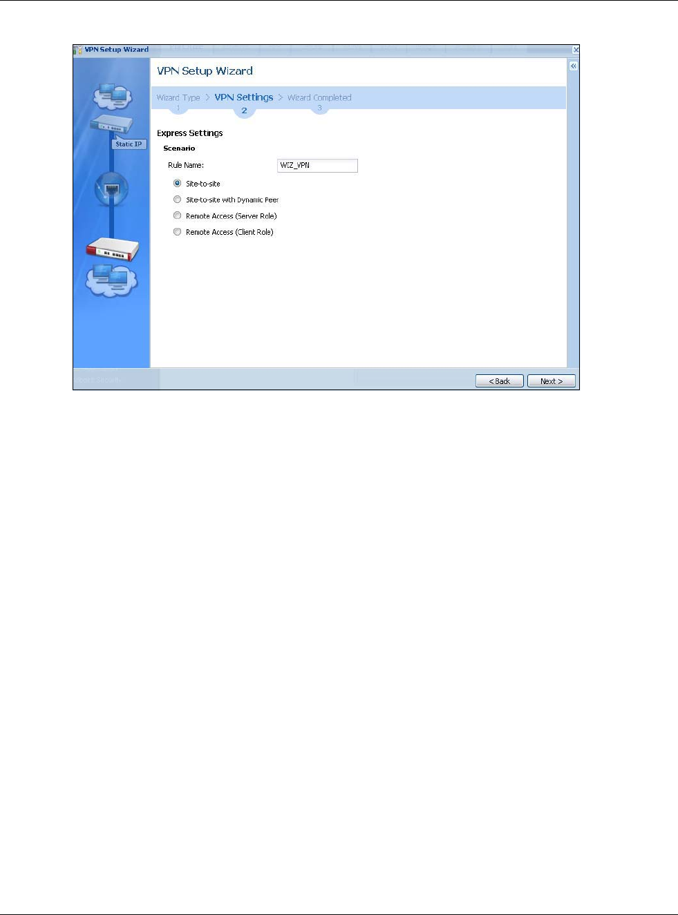
Chapter 4 Quick Setup Wizards
USG20(W)-VPN Series User’s Guide
58
Figure 47 VPN Express Wizard: Scenario
Rule Name: Type the name used to identify this VPN connection (and VPN gateway). You may use
1-31 alphanumeric characters, underscores (_), or dashes (-), but the first character cannot be a
number. This value is case-sensitive.
Select the scenario that best describes your intended VPN connection. The figure on the left of the
screen changes to match the scenario you select.
•Site-to-site - The remote IPSec device has a static IP address or a domain name. This USG can
initiate the VPN tunnel.
•Site-to-site with Dynamic Peer - The remote IPSec device has a dynamic IP address. Only the
remote IPSec device can initiate the VPN tunnel.
•Remote Access (Server Role) - Allow incoming connections from IPSec VPN clients. The
clients have dynamic IP addresses and are also known as dial-in users. Only the clients can
initiate the VPN tunnel.
•Remote Access (Client Role) - Connect to an IPSec server. This USG is the client (dial-in user)
and can initiate the VPN tunnel.
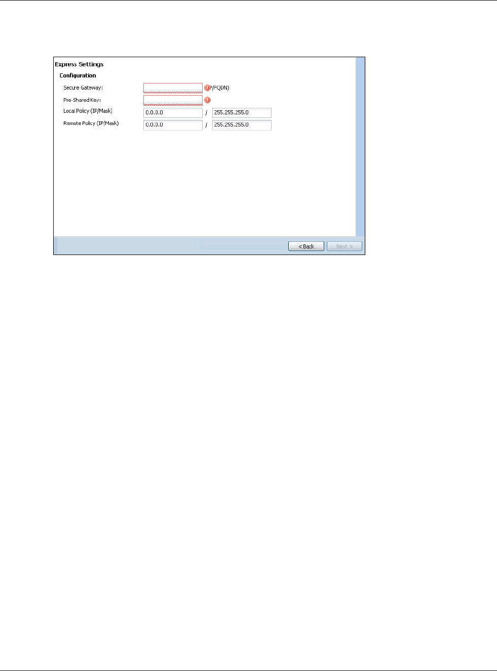
Chapter 4 Quick Setup Wizards
USG20(W)-VPN Series User’s Guide
59
4.3.4 VPN Express Wizard - Configuration
Figure 48 VPN Express Wizard: Configuration
•Secure Gateway: Any displays in this field if it is not configurable for the chosen scenario.
Otherwise, enter the WAN IP address or domain name of the remote IPSec device (secure
gateway) to identify the remote IPSec router by its IP address or a domain name. Use 0.0.0.0 if
the remote IPSec router has a dynamic WAN IP address.
•Pre-Shared Key: Type the password. Both ends of the VPN tunnel must use the same password.
Use 8 to 31 case-sensitive ASCII characters or 8 to 31 pairs of hexadecimal (“0-9”, “A-F”)
characters. Proceed a hexadecimal key with “0x”. You will receive a PYLD_MALFORMED (payload
malformed) packet if the same pre-shared key is not used on both ends.
•Local Policy (IP/Mask): Type the IP address of a computer on your network that can use the
tunnel. You can also specify a subnet. This must match the remote IP address configured on the
remote IPSec device.
•Remote Policy (IP/Mask): Any displays in this field if it is not configurable for the chosen
scenario. Otherwise, type the IP address of a computer behind the remote IPSec device. You can
also specify a subnet. This must match the local IP address configured on the remote IPSec
device.
4.3.5 VPN Express Wizard - Summary
This screen provides a read-only summary of the VPN tunnel’s configuration and commands that
you can copy and paste into another ZLD-based USG’s command line interface to configure it.
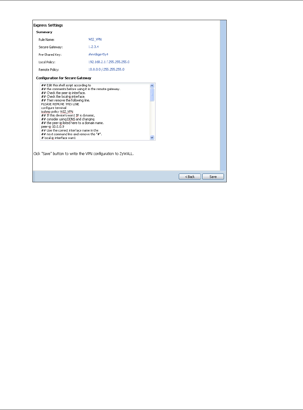
Chapter 4 Quick Setup Wizards
USG20(W)-VPN Series User’s Guide
60
Figure 49 VPN Express Wizard: Summary
•Rule Name: Identifies the VPN gateway policy.
•Secure Gateway: IP address or domain name of the remote IPSec device. If this field displays
Any, only the remote IPSec device can initiate the VPN connection.
•Pre-Shared Key: VPN tunnel password. It identifies a communicating party during a phase 1
IKE negotiation.
•Local Policy: IP address and subnet mask of the computers on the network behind your USG
that can use the tunnel.
•Remote Policy: IP address and subnet mask of the computers on the network behind the
remote IPSec device that can use the tunnel. If this field displays Any, only the remote IPSec
device can initiate the VPN connection.
• Copy and paste the Configuration for Secure Gateway commands into another ZLD-based
USG’s command line interface to configure it to serve as the other end of this VPN tunnel. You
can also use a text editor to save these commands as a shell script file with a “.zysh” filename
extension. Use the file manager to run the script in order to configure the VPN connection. See
the commands reference guide for details on the commands displayed in this list.
4.3.6 VPN Express Wizard - Finish
Now the rule is configured on the USG. The Phase 1 rule settings appear in the VPN > IPSec VPN
> VPN Gateway screen and the Phase 2 rule settings appear in the VPN > IPSec VPN > VPN
Connection screen.
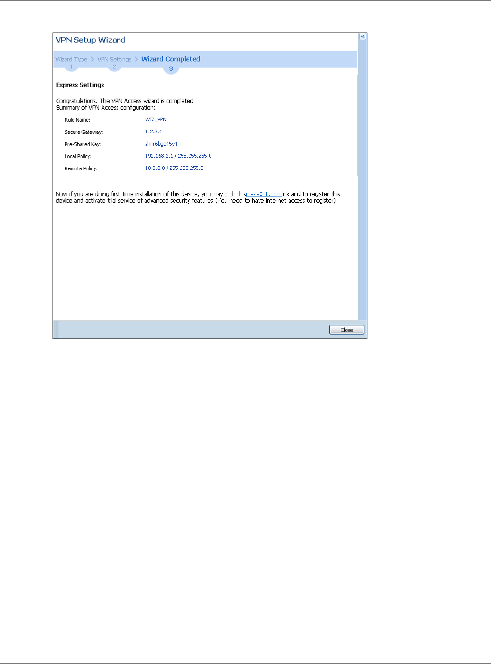
Chapter 4 Quick Setup Wizards
USG20(W)-VPN Series User’s Guide
61
Figure 50 VPN Express Wizard: Finish
Click Close to exit the wizard.
4.3.7 VPN Advanced Wizard - Scenario
Click the Advanced radio button as shown in Figure 46 on page 57 to display the following screen.
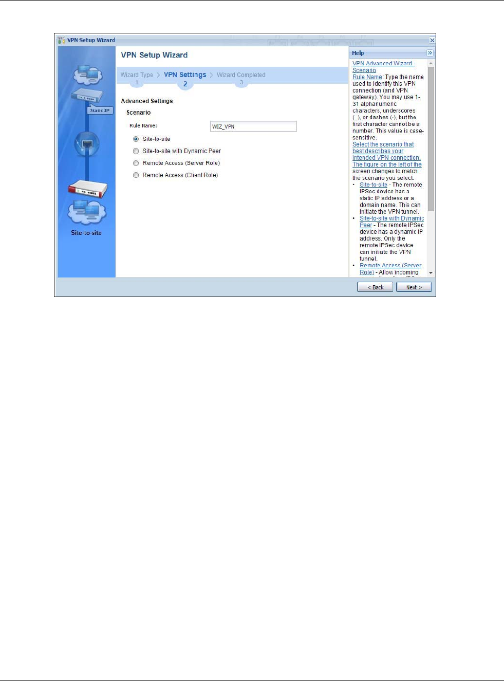
Chapter 4 Quick Setup Wizards
USG20(W)-VPN Series User’s Guide
62
Figure 51 VPN Advanced Wizard: Scenario
Rule Name: Type the name used to identify this VPN connection (and VPN gateway). You may use
1-31 alphanumeric characters, underscores (_), or dashes (-), but the first character cannot be a
number. This value is case-sensitive.
Select the scenario that best describes your intended VPN connection. The figure on the left of the
screen changes to match the scenario you select.
•Site-to-site - The remote IPSec device has a static IP address or a domain name. This USG can
initiate the VPN tunnel.
•Site-to-site with Dynamic Peer - The remote IPSec device has a dynamic IP address. Only the
remote IPSec device can initiate the VPN tunnel.
•Remote Access (Server Role) - Allow incoming connections from IPSec VPN clients. The
clients have dynamic IP addresses and are also known as dial-in users. Only the clients can
initiate the VPN tunnel.
•Remote Access (Client Role) - Connect to an IPSec server. This USG is the client (dial-in user)
and can initiate the VPN tunnel.
4.3.8 VPN Advanced Wizard - Phase 1 Settings
There are two phases to every IKE (Internet Key Exchange) negotiation – phase 1 (Authentication)
and phase 2 (Key Exchange). A phase 1 exchange establishes an IKE SA (Security Association).
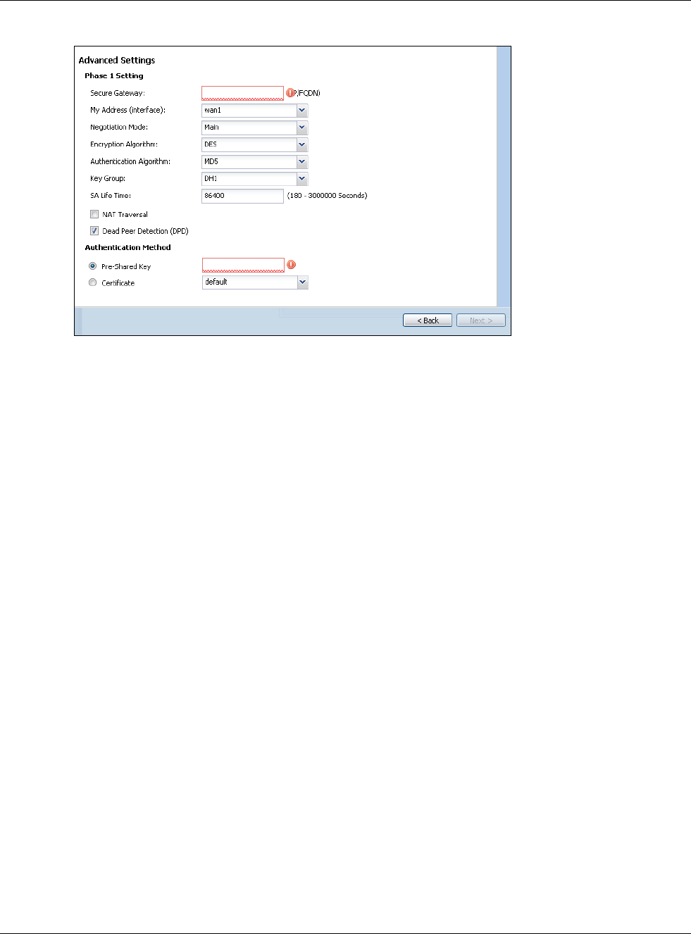
Chapter 4 Quick Setup Wizards
USG20(W)-VPN Series User’s Guide
63
Figure 52 VPN Advanced Wizard: Phase 1 Settings
•Secure Gateway: Any displays in this field if it is not configurable for the chosen scenario.
Otherwise, enter the WAN IP address or domain name of the remote IPSec device (secure
gateway) to identify the remote IPSec device by its IP address or a domain name. Use 0.0.0.0 if
the remote IPSec device has a dynamic WAN IP address.
•My Address (interface): Select an interface from the drop-down list box to use on your USG.
•Negotiation Mode: This displays Main or Aggressive:
•Main encrypts the USG’s and remote IPSec router’s identities but takes more time to establish
the IKE SA
•Aggressive is faster but does not encrypt the identities.
The USG and the remote IPSec router must use the same negotiation mode. Multiple SAs
connecting through a secure gateway must have the same negotiation mode.
•Encryption Algorithm: 3DES and AES use encryption. The longer the key, the higher the
security (this may affect throughput). Both sender and receiver must use the same secret key,
which can be used to encrypt and decrypt the message or to generate and verify a message
authentication code. The DES encryption algorithm uses a 56-bit key. Triple DES (3DES) is a
variation on DES that uses a 168-bit key. As a result, 3DES is more secure than DES. It also
requires more processing power, resulting in increased latency and decreased throughput.
AES128 uses a 128-bit key and is faster than 3DES. AES192 uses a 192-bit key, and AES256
uses a 256-bit key.
•Authentication Algorithm: MD5 gives minimal security and SHA512 gives the highest
security. MD5 (Message Digest 5) and SHA (Secure Hash Algorithm) are hash algorithms used to
authenticate packet data. The stronger the algorithm the slower it is.
•Key Group: DH5 is more secure than DH1 or DH2 (although it may affect throughput). DH1
(default) refers to Diffie-Hellman Group 1 a 768 bit random number. DH2 refers to Diffie-Hellman
Group 2 a 1024 bit (1Kb) random number. DH5 refers to Diffie-Hellman Group 5 a 1536 bit
random number.
•SA Life Time: Set how often the USG renegotiates the IKE SA. A short SA life time increases
security, but renegotiation temporarily disconnects the VPN tunnel.
•NAT Traversal: Select this if the VPN tunnel must pass through NAT (there is a NAT router
between the IPSec devices).
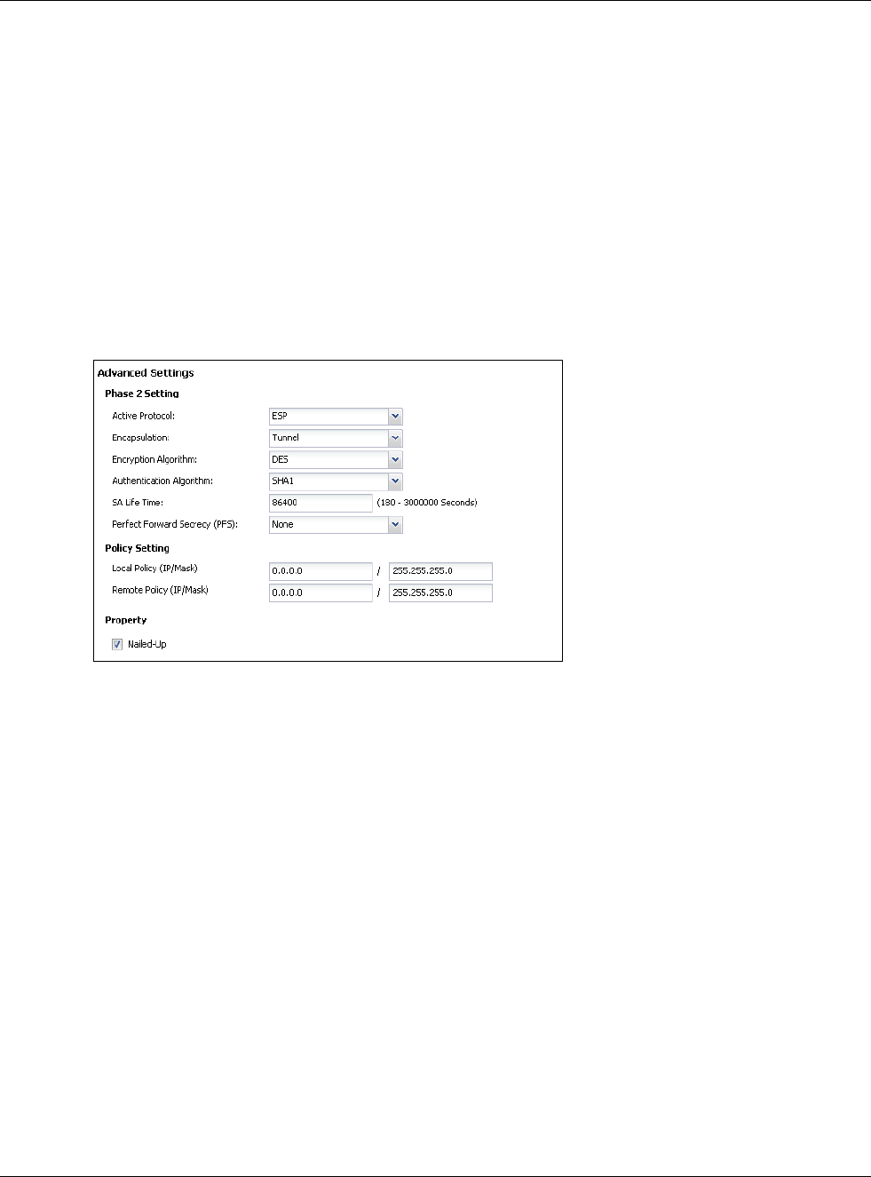
Chapter 4 Quick Setup Wizards
USG20(W)-VPN Series User’s Guide
64
Note: The remote IPSec device must also have NAT traversal enabled. See the help in the
main IPSec VPN screens for more information.
•Dead Peer Detection (DPD) has the USG make sure the remote IPSec device is there before
transmitting data through the IKE SA. If there has been no traffic for at least 15 seconds, the
USG sends a message to the remote IPSec device. If it responds, the USG transmits the data. If
it does not respond, the USG shuts down the IKE SA.
•Authentication Method: Select Pre-Shared Key to use a password or Certificate to use one
of the USG’s certificates.
4.3.9 VPN Advanced Wizard - Phase 2
Phase 2 in an IKE uses the SA that was established in phase 1 to negotiate SAs for IPSec.
Figure 53 VPN Advanced Wizard: Phase 2 Settings
•Active Protocol: ESP is compatible with NAT, AH is not.
•Encapsulation: Tunnel is compatible with NAT, Transport is not.
•Encryption Algorithm: 3DES and AES use encryption. The longer the AES key, the higher the
security (this may affect throughput). Null uses no encryption.
•Authentication Algorithm: MD5 gives minimal security and SHA512 gives the highest
security. MD5 (Message Digest 5) and SHA (Secure Hash Algorithm) are hash algorithms used to
authenticate packet data. The stronger the algorithm the slower it is.
•SA Life Time: Set how often the USG renegotiates the IKE SA. A short SA life time increases
security, but renegotiation temporarily disconnects the VPN tunnel.
•Perfect Forward Secrecy (PFS): Disabling PFS allows faster IPSec setup, but is less secure.
Select DH1, DH2 or DH5 to enable PFS. DH5 is more secure than DH1 or DH2 (although it may
affect throughput). DH1 refers to Diffie-Hellman Group 1 a 768 bit random number. DH2 refers to
Diffie-Hellman Group 2 a 1024 bit (1Kb) random number. DH5 refers to Diffie-Hellman Group 5 a
1536 bit random number (more secure, yet slower).
•Local Policy (IP/Mask): Type the IP address of a computer on your network. You can also
specify a subnet. This must match the remote IP address configured on the remote IPSec device.
•Remote Policy (IP/Mask): Type the IP address of a computer behind the remote IPSec device.
You can also specify a subnet. This must match the local IP address configured on the remote
IPSec device.
•Nailed-Up: This displays for the site-to-site and remote access client role scenarios. Select this
to have the USG automatically renegotiate the IPSec SA when the SA life time expires.
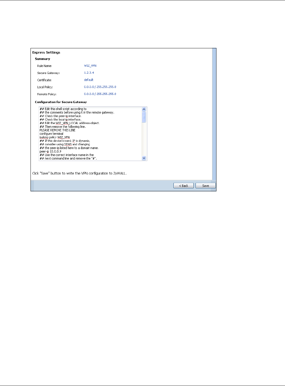
Chapter 4 Quick Setup Wizards
USG20(W)-VPN Series User’s Guide
65
4.3.10 VPN Advanced Wizard - Summary
This is a read-only summary of the VPN tunnel settings.
Figure 54 VPN Advanced Wizard: Summary
•Rule Name: Identifies the VPN connection (and the VPN gateway).
•Secure Gateway: IP address or domain name of the remote IPSec device.
•Pre-Shared Key: VPN tunnel password.
•Certificate: The certificate the USG uses to identify itself when setting up the VPN tunnel.
•Local Policy: IP address and subnet mask of the computers on the network behind your USG
that can use the tunnel.
•Remote Policy: IP address and subnet mask of the computers on the network behind the
remote IPSec device that can use the tunnel.
• Copy and paste the Configuration for Remote Gateway commands into another ZLD-based
USG’s command line interface.
• Click Save to save the VPN rule.
4.3.11 VPN Advanced Wizard - Finish
Now the rule is configured on the USG. The Phase 1 rule settings appear in the VPN > IPSec VPN
> VPN Gateway screen and the Phase 2 rule settings appear in the VPN > IPSec VPN > VPN
Connection screen.
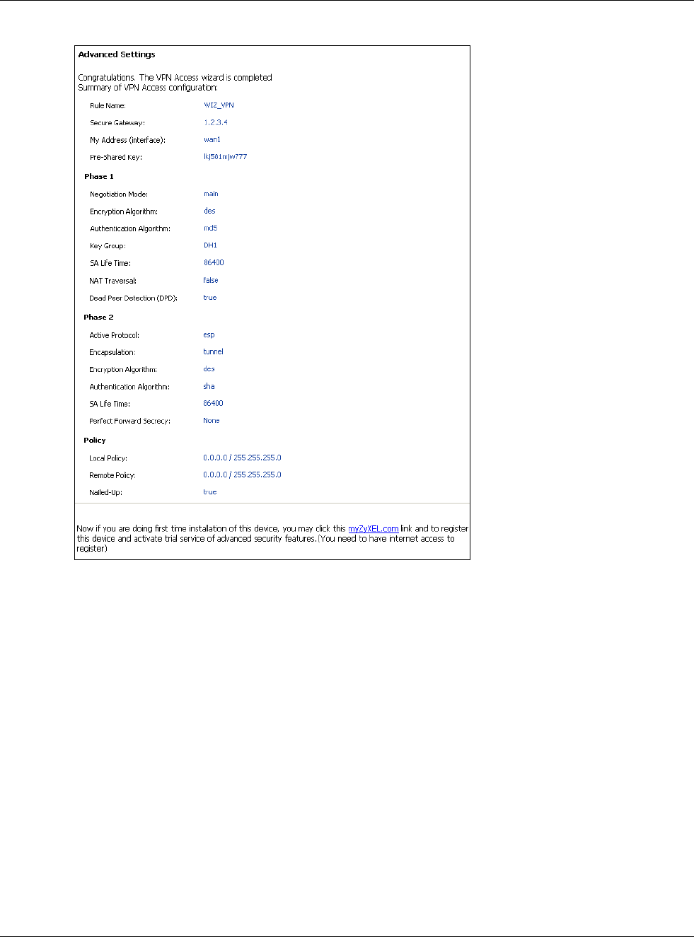
Chapter 4 Quick Setup Wizards
USG20(W)-VPN Series User’s Guide
66
Figure 55 VPN Wizard: Finish
Click Close to exit the wizard.
4.4 VPN Settings for Configuration Provisioning Wizard:
Wizard Type
Use VPN Settings for Configuration Provisioning to set up a VPN rule that can be retrieved
with the USG IPSec VPN Client.
VPN rules for the USG IPSec VPN Client have certain restrictions. They must not contain the
following settings:
•AH active protocol
•NULL encryption
•SHA512 authentication
• A subnet or range remote policy
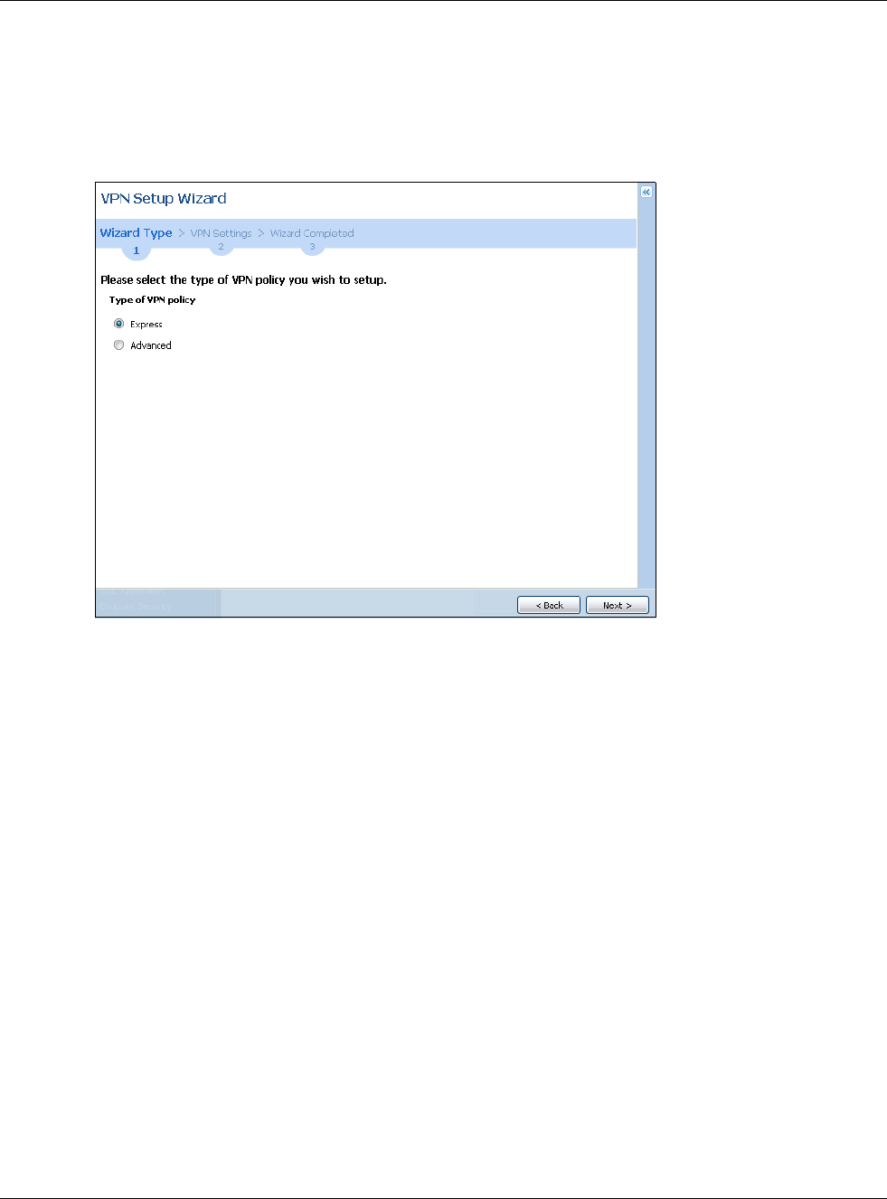
Chapter 4 Quick Setup Wizards
USG20(W)-VPN Series User’s Guide
67
Choose Express to create a VPN rule with the default phase 1 and phase 2 settings and to use a
pre-shared key.
Choose Advanced to change the default settings and/or use certificates instead of a pre-shared
key in the VPN rule.
Figure 56 VPN Settings for Configuration Provisioning Express Wizard: Wizard Type
4.4.1 Configuration Provisioning Express Wizard - VPN Settings
Click the Express radio button as shown in the previous screen to display the following screen.
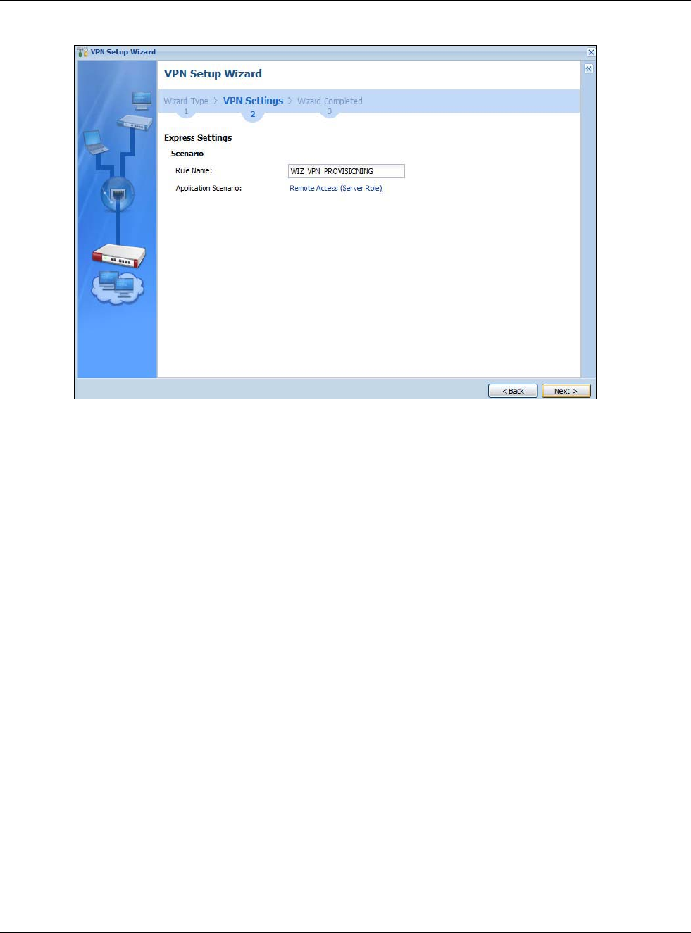
Chapter 4 Quick Setup Wizards
USG20(W)-VPN Series User’s Guide
68
Figure 57 VPN for Configuration Provisioning Express Wizard: Settings Scenario
Rule Name: Type the name used to identify this VPN connection (and VPN gateway). You may use
1-31 alphanumeric characters, underscores (_), or dashes (-), but the first character cannot be a
number. This value is case-sensitive.
Application Scenario: Only the Remote Access (Server Role) is allowed in this wizard. It
allows incoming connections from the USG IPSec VPN Client.
4.4.2 Configuration Provisioning VPN Express Wizard - Configuration
Click Next to continue the wizard.

Chapter 4 Quick Setup Wizards
USG20(W)-VPN Series User’s Guide
69
Figure 58 VPN for Configuration Provisioning Express Wizard: Configuration
•Secure Gateway: Any displays in this field because it is not configurable in this wizard. It allows
incoming connections from the USG IPSec VPN Client.
•Pre-Shared Key: Type the password. Both ends of the VPN tunnel must use the same password.
Use 8 to 31 case-sensitive ASCII characters or 8 to 31 pairs of hexadecimal (“0-9”, “A-F”)
characters. Proceed a hexadecimal key with “0x”. You will receive a PYLD_MALFORMED (payload
malformed) packet if the same pre-shared key is not used on both ends.
•Local Policy (IP/Mask): Type the IP address of a computer on your network. You can also
specify a subnet. This must match the remote IP address configured on the remote IPSec device.
•Remote Policy (IP/Mask): Any displays in this field because it is not configurable in this
wizard.
4.4.3 VPN Settings for Configuration Provisioning Express Wizard -
Summary
This screen has a read-only summary of the VPN tunnel’s configuration and commands you can
copy and paste into another ZLD-based USG’s command line interface to configure it.
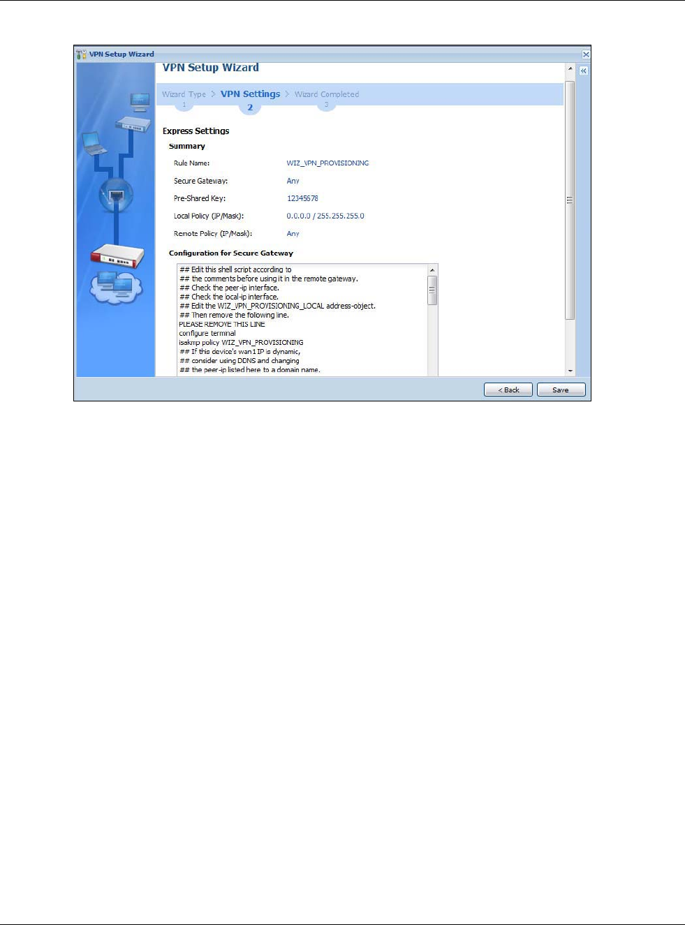
Chapter 4 Quick Setup Wizards
USG20(W)-VPN Series User’s Guide
70
Figure 59 VPN for Configuration Provisioning Express Wizard: Summary
•Rule Name: Identifies the VPN gateway policy.
•Secure Gateway: Any displays in this field because it is not configurable in this wizard. It allows
incoming connections from the USG IPSec VPN Client.
•Pre-Shared Key: VPN tunnel password. It identifies a communicating party during a phase 1
IKE negotiation.
•Local Policy: (Static) IP address and subnet mask of the computers on the network behind your
USG that can be accessed using the tunnel.
•Remote Policy: Any displays in this field because it is not configurable in this wizard.
•The Configuration for Secure Gateway displays the configuration that the USG IPSec VPN
Client will get from the USG.
• Click Save to save the VPN rule.
4.4.4 VPN Settings for Configuration Provisioning Express Wizard - Finish
Now the rule is configured on the USG. The Phase 1 rule settings appear in the VPN > IPSec VPN
> VPN Gateway screen and the Phase 2 rule settings appear in the VPN > IPSec VPN > VPN
Connection screen. Enter the IP address of the USG in the USG IPSec VPN Client to get all these
VPN settings automatically from the USG.
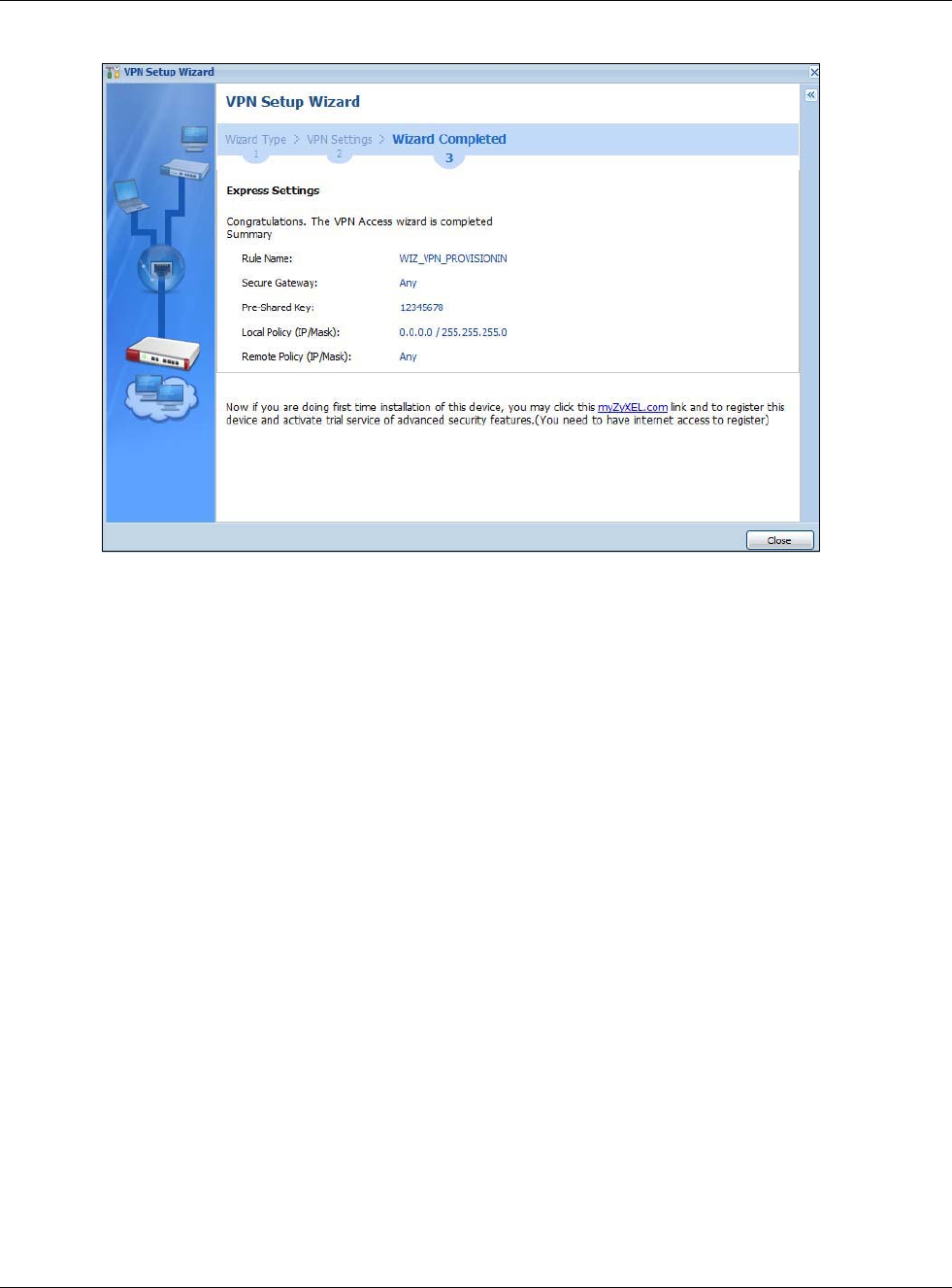
Chapter 4 Quick Setup Wizards
USG20(W)-VPN Series User’s Guide
71
Figure 60 VPN for Configuration Provisioning Express Wizard: Finish
Click Close to exit the wizard.
4.4.5 VPN Settings for Configuration Provisioning Advanced Wizard -
Scenario
Click the Advanced radio button as shown in the screen shown in Figure 56 on page 67 to display
the following screen.

Chapter 4 Quick Setup Wizards
USG20(W)-VPN Series User’s Guide
72
Figure 61 VPN for Configuration Provisioning Advanced Wizard: Scenario Settings
Rule Name: Type the name used to identify this VPN connection (and VPN gateway). You may use
1-31 alphanumeric characters, underscores (_), or dashes (-), but the first character cannot be a
number. This value is case-sensitive.
Application Scenario: Only the Remote Access (Server Role) is allowed in this wizard. It
allows incoming connections from the USG IPSec VPN Client.
Click Next to continue the wizard.
4.4.6 VPN Settings for Configuration Provisioning Advanced Wizard - Phase
1 Settings
There are two phases to every IKE (Internet Key Exchange) negotiation – phase 1 (Authentication)
and phase 2 (Key Exchange). A phase 1 exchange establishes an IKE SA (Security Association).
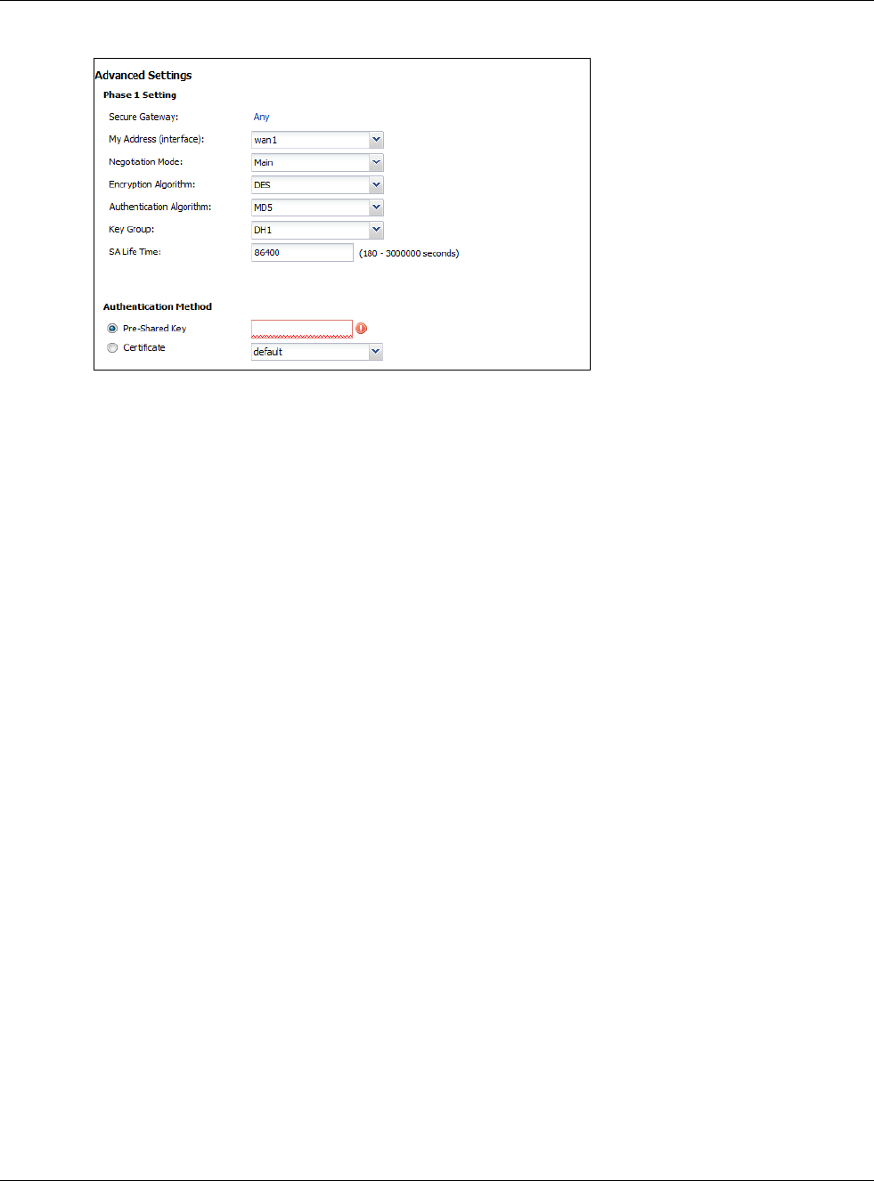
Chapter 4 Quick Setup Wizards
USG20(W)-VPN Series User’s Guide
73
Figure 62 VPN for Configuration Provisioning Advanced Wizard: Phase 1 Settings
•Secure Gateway: Any displays in this field because it is not configurable in this wizard. It allows
incoming connections from the USG IPSec VPN Client.
•My Address (interface): Select an interface from the drop-down list box to use on your USG.
•Negotiation Mode:This displays Main or Aggressive:
•Main encrypts the USG’s and remote IPSec router’s identities but takes more time to establish
the IKE SA
•Aggressive is faster but does not encrypt the identities.
The USG and the remote IPSec router must use the same negotiation mode. Multiple SAs
connecting through a secure gateway must have the same negotiation mode.
•Encryption Algorithm: 3DES and AES use encryption. The longer the key, the higher the
security (this may affect throughput). Both sender and receiver must know the same secret key,
which can be used to encrypt and decrypt the message or to generate and verify a message
authentication code. The DES encryption algorithm uses a 56-bit key. Triple DES (3DES) is a
variation on DES that uses a 168-bit key. As a result, 3DES is more secure than DES. It also
requires more processing power, resulting in increased latency and decreased throughput.
AES128 uses a 128-bit key and is faster than 3DES. AES192 uses a 192-bit key and AES256 uses
a 256-bit key.
•Authentication Algorithm: MD5 (Message Digest 5) and SHA (Secure Hash Algorithm) are
hash algorithms used to authenticate packet data. MD5 gives minimal security. SHA1 gives
higher security and SHA256 gives the highest security. The stronger the algorithm, the slower it
is.
•Key Group: DH5 is more secure than DH1 or DH2 (although it may affect throughput). DH1
(default) refers to Diffie-Hellman Group 1 a 768 bit random number. DH2 refers to Diffie-Hellman
Group 2 a 1024 bit (1Kb) random number. DH5 refers to Diffie-Hellman Group 5 a 1536 bit
random number.
•SA Life Time: Set how often the USG renegotiates the IKE SA. A short SA life time increases
security, but renegotiation temporarily disconnects the VPN tunnel.
•Authentication Method: Select Pre-Shared Key to use a password or Certificate to use one
of the USG’s certificates.
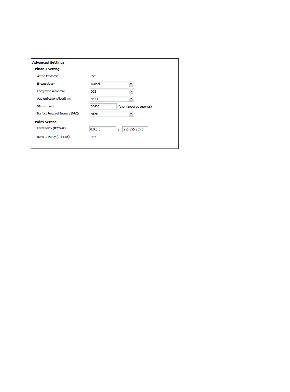
Chapter 4 Quick Setup Wizards
USG20(W)-VPN Series User’s Guide
74
4.4.7 VPN Settings for Configuration Provisioning Advanced Wizard - Phase
2
Phase 2 in an IKE uses the SA that was established in phase 1 to negotiate SAs for IPSec.
Figure 63 VPN for Configuration Provisioning Advanced Wizard: Phase 2 Settings
•Active Protocol: ESP is compatible with NAT. AH is not available in this wizard.
•Encapsulation: Tunnel is compatible with NAT, Transport is not.
•Encryption Algorithm: 3DES and AES use encryption. The longer the AES key, the higher the
security (this may affect throughput). Null uses no encryption.
•Authentication Algorithm: MD5 (Message Digest 5) and SHA (Secure Hash Algorithm) are
hash algorithms used to authenticate packet data. MD5 gives minimal security. SHA1 gives
higher security and SHA256 gives the highest security. The stronger the algorithm, the slower it
is.
•SA Life Time: Set how often the USG renegotiates the IKE SA. A short SA life time increases
security, but renegotiation temporarily disconnects the VPN tunnel.
•Perfect Forward Secrecy (PFS): Disabling PFS allows faster IPSec setup, but is less secure.
Select DH1, DH2 or DH5 to enable PFS. DH5 is more secure than DH1 or DH2 (although it may
affect throughput). DH1 refers to Diffie-Hellman Group 1 a 768 bit random number. DH2 refers to
Diffie-Hellman Group 2 a 1024 bit (1Kb) random number. DH5 refers to Diffie-Hellman Group 5 a
1536 bit random number (more secure, yet slower).
•Local Policy (IP/Mask): Type the IP address of a computer on your network. You can also
specify a subnet. This must match the remote IP address configured on the remote IPSec device.
•Remote Policy (IP/Mask): Any displays in this field because it is not configurable in this
wizard.
•Nailed-Up: This displays for the site-to-site and remote access client role scenarios. Select this
to have the USG automatically renegotiate the IPSec SA when the SA life time expires.
4.4.8 VPN Settings for Configuration Provisioning Advanced Wizard -
Summary
This is a read-only summary of the VPN tunnel settings.
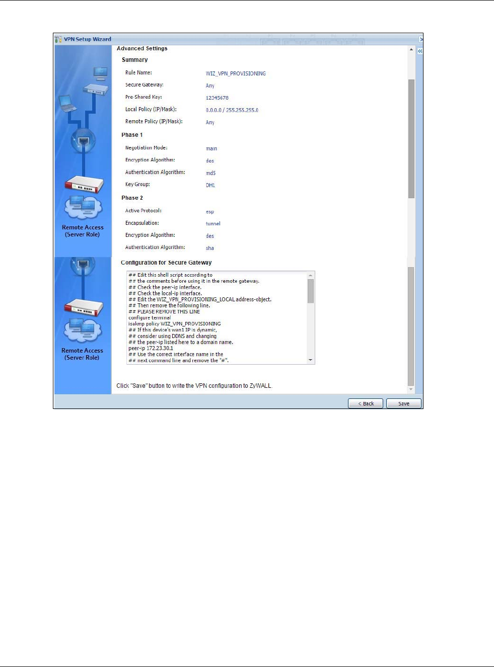
Chapter 4 Quick Setup Wizards
USG20(W)-VPN Series User’s Guide
75
Figure 64 VPN for Configuration Provisioning Advanced Wizard: Summary
Summary
•Rule Name: Identifies the VPN connection (and the VPN gateway).
•Secure Gateway: Any displays in this field because it is not configurable in this wizard. It
allows incoming connections from the USG IPSec VPN Client.
•Pre-Shared Key: VPN tunnel password.
•Local Policy: IP address and subnet mask of the computers on the network behind your USG
that can use the tunnel.
•Remote Policy: Any displays in this field because it is not configurable in this wizard.
Phase 1
•Negotiation Mode: This displays Main or Aggressive:
•Main encrypts the USG’s and remote IPSec router’s identities but takes more time to establish
the IKE SA
•Aggressive is faster but does not encrypt the identities.
The USG and the remote IPSec router must use the same negotiation mode. Multiple SAs
connecting through a secure gateway must have the same negotiation mode.

Chapter 4 Quick Setup Wizards
USG20(W)-VPN Series User’s Guide
76
•Encryption Algorithm: This displays the encryption method used. The longer the key, the
higher the security, the lower the throughput (possibly).
•DES uses a 56-bit key.
•3DES uses a 168-bit key.
•AES128 uses a 128-bit key
•AES192 uses a 192-bit key
•AES256 uses a 256-bit key.
•Authentication Algorithm: This displays the authentication algorithm used. The stronger the
algorithm, the slower it is.
•MD5 gives minimal security.
•SHA1 gives higher security
•SHA256 gives the highest security.
•Key Group: This displays the Diffie-Hellman (DH) key group used. DH5 is more secure than
DH1 or DH2 (although it may affect throughput).
•DH1 uses a 768 bit random number.
•DH2 uses a 1024 bit (1Kb) random number.
•DH5 uses a 1536 bit random number.
Phase 2
•Active Protocol: This displays ESP (compatible with NAT) or AH.
•Encapsulation: This displays Tunnel (compatible with NAT) or Transport.
•Encryption Algorithm: This displays the encryption method used. The longer the key, the
higher the security, the lower the throughput (possibly).
•DES uses a 56-bit key.
•3DES uses a 168-bit key.
•AES128 uses a 128-bit key
•AES192 uses a 192-bit key
•AES256 uses a 256-bit key.
•Null uses no encryption.
•Authentication Algorithm: This displays the authentication algorithm used. The stronger the
algorithm, the slower it is.
•MD5 gives minimal security.
•SHA1 gives higher security
•SHA256 gives the highest security..
The Configuration for Secure Gateway displays the configuration that the USG IPSec VPN Client
will get from the USG.
Click Save to save the VPN rule.
4.4.9 VPN Settings for Configuration Provisioning Advanced Wizard- Finish
Now the rule is configured on the USG. The Phase 1 rule settings appear in the VPN > IPSec VPN
> VPN Gateway screen and the Phase 2 rule settings appear in the VPN > IPSec VPN > VPN
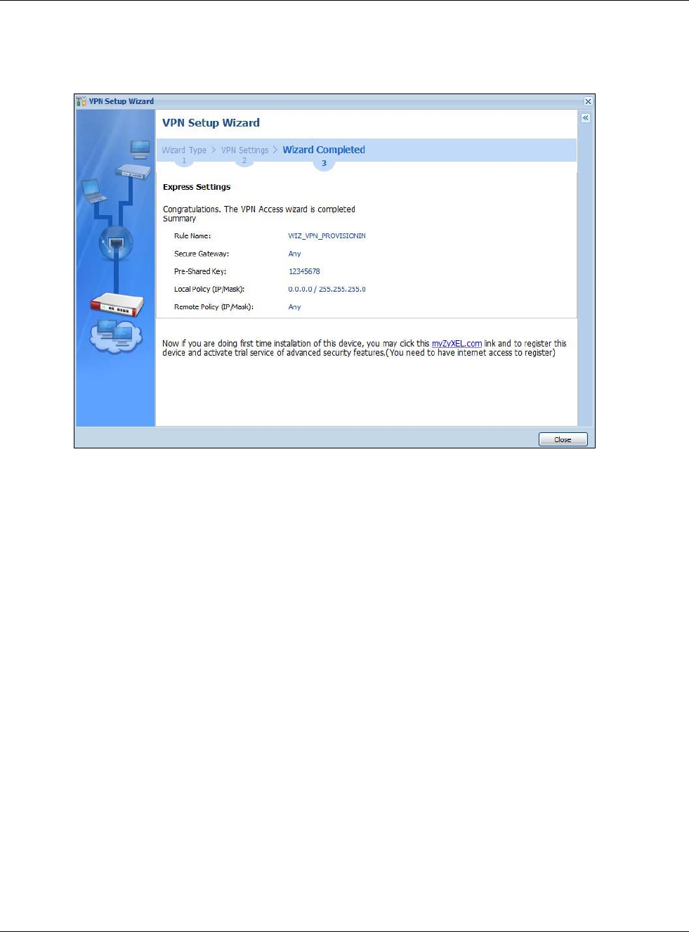
Chapter 4 Quick Setup Wizards
USG20(W)-VPN Series User’s Guide
77
Connection screen. Enter the IP address of the USG in the USG IPSec VPN Client to get all these
VPN settings automatically from the USG.
Figure 65 VPN for Configuration Provisioning Advanced Wizard: Finish
Click Close to exit the wizard.
4.5 VPN Settings for L2TP VPN Settings Wizard
Use VPN Settings for L2TP VPN Settings to set up an L2TP VPN rule. Click Configuration >
Quick Setup > VPN Settings and select VPN Settings for L2TP VPN Settings to see the
following screen.
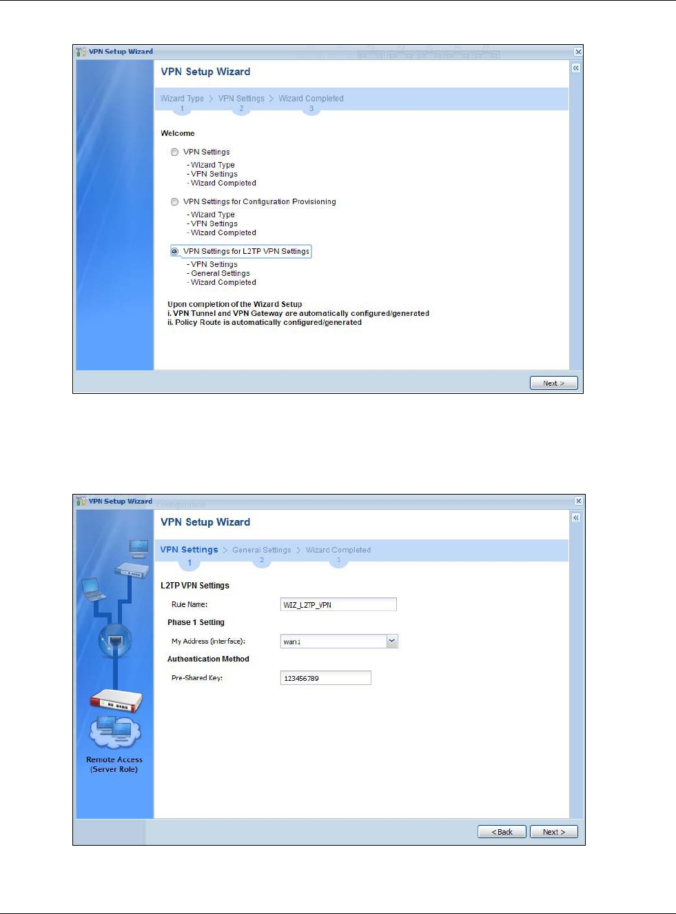
Chapter 4 Quick Setup Wizards
USG20(W)-VPN Series User’s Guide
78
Figure 66 VPN Settings for L2TP VPN Settings Wizard: L2TP VPN Settings
Click Next to continue the wizard.
4.5.1 L2TP VPN Settings
Figure 67 VPN Settings for L2TP VPN Settings Wizard: L2TP VPN Settings
•Rule Name: Type the name used to identify this L2TP VPN connection (and L2TP VPN gateway).
You may use 1-31 alphanumeric characters, underscores (_), or dashes (-), but the first
character cannot be a number. This value is case-sensitive.
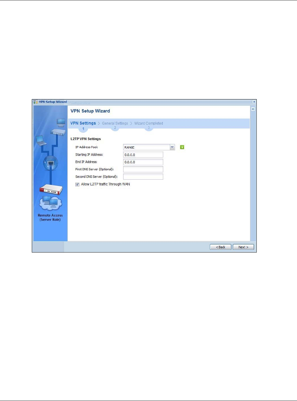
Chapter 4 Quick Setup Wizards
USG20(W)-VPN Series User’s Guide
79
•My Address (interface): Select one of the interfaces from the pull down menu to apply the
L2TP VPN rule.
•Pre-Shared Key: Type the password. Both ends of the VPN tunnel must use the same password.
Use 8 to 31 case-sensitive ASCII characters or 8 to 31 pairs of hexadecimal (“0-9”, “A-F”)
characters. Proceed a hexadecimal key with “0x”. You will receive a PYLD_MALFORMED (payload
malformed) packet if the same pre-shared key is not used on both ends.
Click Next to continue the wizard.
4.5.2 L2TP VPN Settings
Figure 68 VPN Settings for L2TP VPN Settings Wizard: L2TP VPN Settings
•IP Address Pool: Select Range or Subnet from the pull down menu. This IP address pool is used
to assign to the L2TP VPN clients.
•Starting IP Address: Enter the starting IP address in the field.
•End IP Address: Enter the ending IP address in the field.
•First DNS Server (Optional): Enter the first DNS server IP address in the field. Leave the filed
as 0.0.0.0 if you do not want to configure DNS servers. If you do not configure a DNS server you
must know the IP address of a machine in order to access it.
•Second DNS Server (Optional):Enter the second DNS server IP address in the field. Leave the
filed as 0.0.0.0 if you do not want to configure DNS servers. If you do not configure a DNS server
you must know the IP address of a machine in order to access it.
•Allow L2TP traffic Through WAN: Select this check box to allow traffic from L2TP clients to go
to the Internet.
Click Next to continue the wizard.
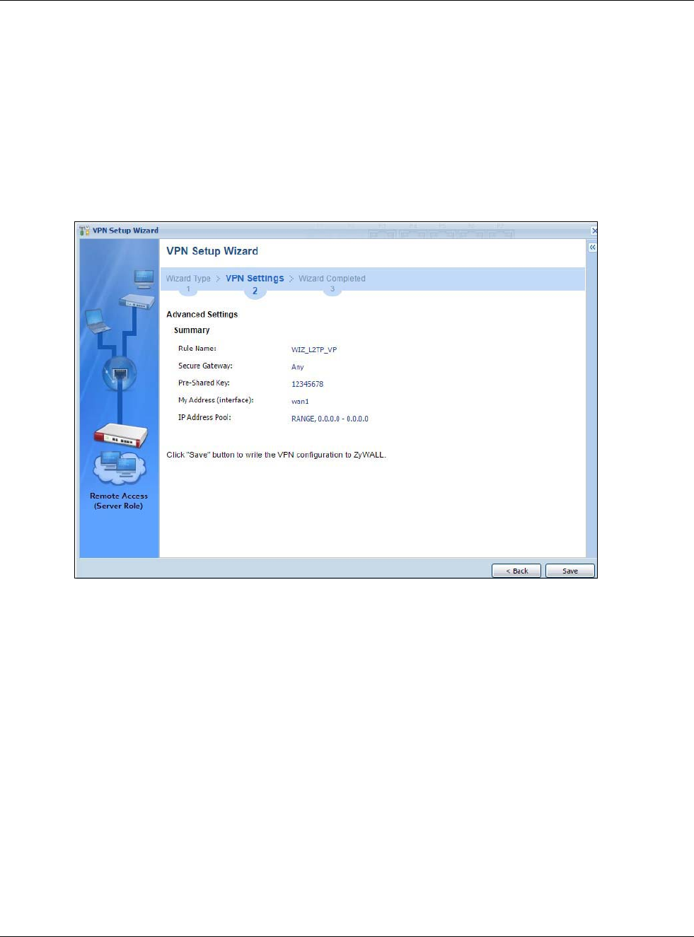
Chapter 4 Quick Setup Wizards
USG20(W)-VPN Series User’s Guide
80
Note: DNS (Domain Name System) is for mapping a domain name to its corresponding IP
address and vice versa. The DNS server is extremely important because without it,
you must know the IP address of a computer before you can access it. The USG
uses a system DNS server (in the order you specify here) to resolve domain names
for VPN, DDNS and the time server.
4.5.3 VPN Settings for L2TP VPN Setting Wizard - Summary
This is a read-only summary of the L2TP VPN settings.
Figure 69 VPN Settings for L2TP VPN Settings Advanced Settings Wizard: Summary
Summary
•Rule Name: Identifies the L2TP VPN connection (and the L2TP VPN gateway).
•Secure Gateway: “Any” displays in this field because it is not configurable in this wizard. It
allows incoming connections from the L2TP VPN Client.
•Pre-Shared Key: L2TP VPN tunnel password.
•My Address (Interface): This displays the interface to use on your USG for the L2TP tunnel.
•IP Address Pool: This displays the IP address pool used to assign to the L2TP VPN clients.
Click Save to complete the L2TP VPN Setting and the following screen will show.
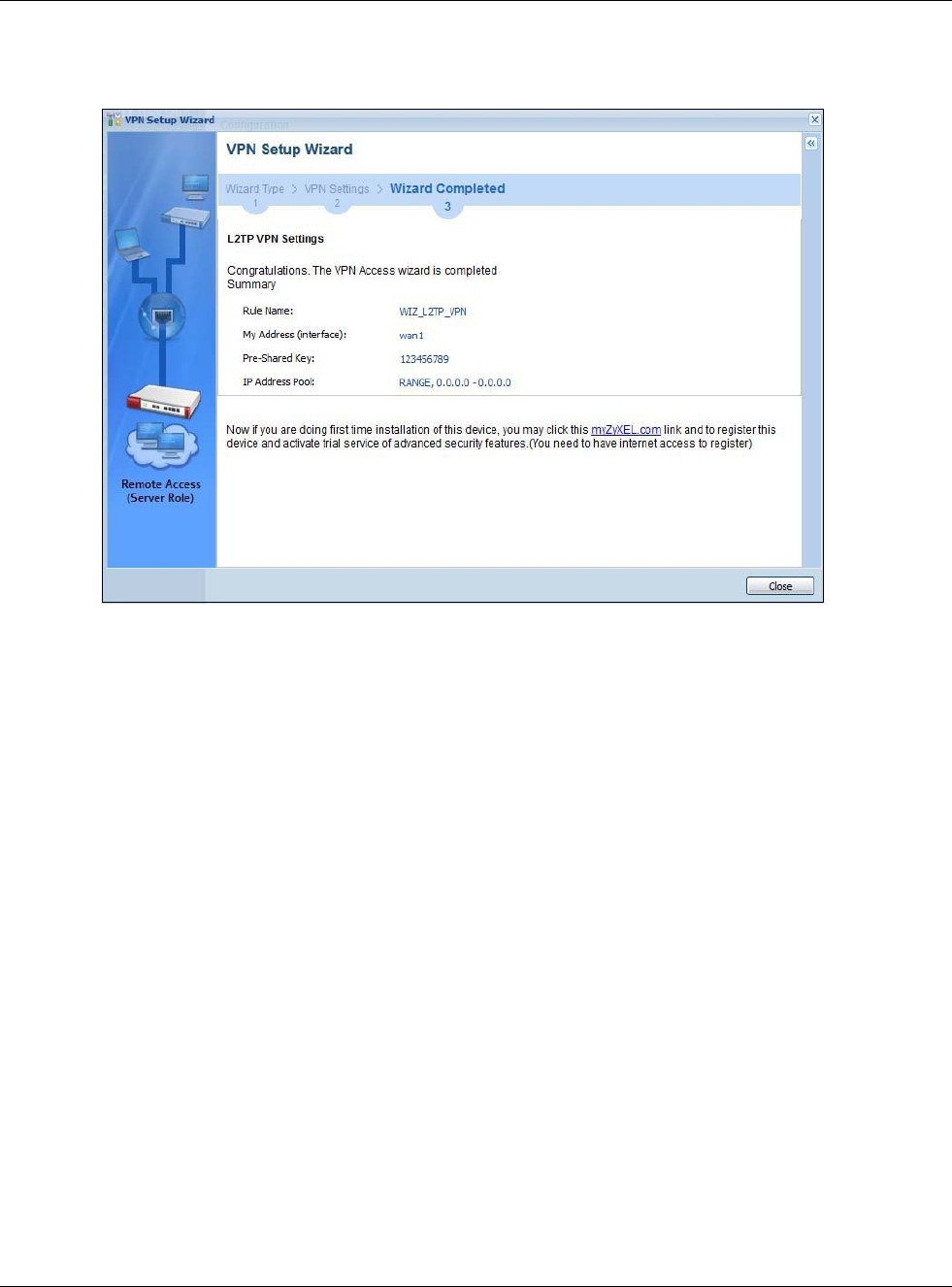
Chapter 4 Quick Setup Wizards
USG20(W)-VPN Series User’s Guide
81
4.5.4 VPN Settings for L2TP VPN Setting Wizard Completed
Figure 70 VPN Settings for L2TP VPN Settings Wizard: Finish
Now the rule is configured on the USG. The L2TP VPN rule settings appear in the VPN > L2TP VPN
screen and also in the VPN > IPSec VPN > VPN Connection and VPN Gateway screen.

USG20(W)-VPN Series User’s Guide
82
CHAPTER 5
Dashboard
5.1 Overview
Use the Dashboard screens to check status information about the USG.
5.1.1 What You Can Do in this Chapter
Use the main Dashboard screen to see the USG’s general device information, system status,
system resource usage, licensed service status, and interface status. You can also display other
status screens for more information.
Use the Dashboard screens to view the following.
•Device Information Screen on page 84
•System Status Screen on page 85
•VPN Status Screen on page 86
•DHCP Table Screen on page 87
•Number of Login Users Screen on page 88
•System Resources Screen on page 89
•CPU Usage Screen on page 90
•Memory Usage Screen on page 91
•Active Session Screen on page 92
•Extension Slot Screen on page 93
•Interface Status Summary Screen on page 93
•Secured Service Status Screen on page 94
•Content Filter Statistics Screen on page 95
•Top 5 IPv4/IPv6 Security Policy Rules that Blocked Traffic Screen on page 96
•Top 5 IPv4/IPv6 Security Policy Rules that Blocked Traffic Screen on page 96
•Top 5 IPv4/IPv6 Security Policy Rules that Blocked Traffic Screen on page 96
•The Latest Alert Logs Screen on page 96
5.2 Main Dashboard Screen
The Dashboard screen displays when you log into the USG or click Dashboard in the navigation
panel. The dashboard displays general device information, system status, system resource usage,
licensed service status, and interface status in widgets that you can re-arrange to suit your needs.
You can also collapse, refresh, and close individual widgets.
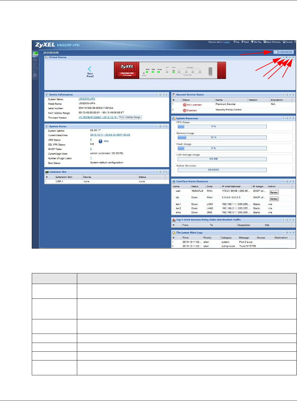
Chapter 5 Dashboard
USG20(W)-VPN Series User’s Guide
83
Click on the icon to go to the OneSecurity.com website where there is guidance on configuration
walkthroughs, troubleshooting, and other information.
Figure 71 Dashboard
The following table describes the labels in this screen.
Table 16 Dashboard
LABEL DESCRIPTION
Widget Settings
(A)
Use this link to open or close widgets by selecting/clearing the associated checkbox.
expand /
collapse widget
(B)
Click this to collapse a widget. It then becomes a down arrow. Click it again to enlarge the
widget again.
Refresh time
setting (C)
Set the interval for refreshing the information displayed in the widget.
Refresh Now (D) Click this to update the widget’s information immediately.
Close widget (E) Click this to close the widget. Use Widget Setting to re-open it.
Virtual Device
Rear Panel Click this to view details about the USG’s rear panel. Hover your cursor over a connected
interface or slot to display status details.
A
BCDE
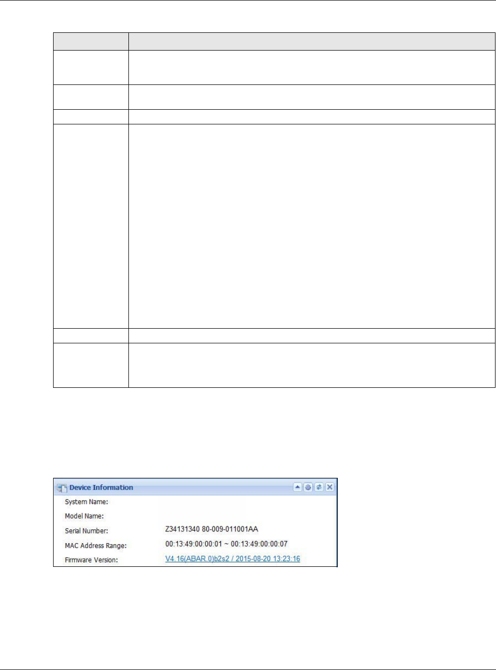
Chapter 5 Dashboard
USG20(W)-VPN Series User’s Guide
84
5.2.1 Device Information Screen
The Device Information screen displays USG’s system and model name, serial number, MAC
address and firmware version shown in the below screen.
Figure 72 Dashboard > Device Information (Example)
Front Panel Click this to view details about the status of the USG’s front panel LEDs and connections.
See Section 3.1.1 on page 44 for LED descriptions. An unconnected interface or slot
appears grayed out.
The following front and rear panel labels display when you hover your cursor over a
connected interface or slot.
Name This field displays the name of each interface.
Status This field displays the current status of each interface or device installed in a slot. The
possible values depend on what type of interface it is.
Inactive - The Ethernet interface is disabled.
Down - The Ethernet interface does not have any physical ports associated with it or the
Ethernet interface is enabled but not connected.
Speed / Duplex - The Ethernet interface is enabled and connected. This field displays the
port speed and duplex setting (Full or Half).
The status for a WLAN card is none.
For cellular (mobile broadband) interfaces, see Section 9.5 on page 173 for the status that
can appear.
For the auxiliary interface:
Inactive - The auxiliary interface is disabled.
Connected - The auxiliary interface is enabled and connected.
Disconnected - The auxiliary interface is not connected.
Zone This field displays the zone to which the interface is currently assigned.
IP Address/
Mask This field displays the current IP address and subnet mask assigned to the interface. If the
interface is a member of an active virtual router, this field displays the IP address it is
currently using. This is either the static IP address of the interface (if it is the master) or
the management IP address (if it is a backup).
Table 16 Dashboard (continued)
LABEL DESCRIPTION
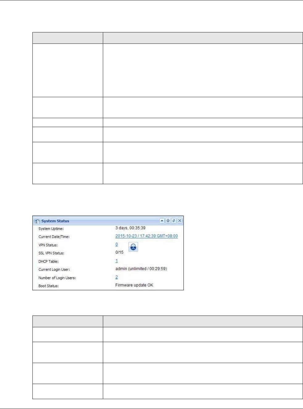
Chapter 5 Dashboard
USG20(W)-VPN Series User’s Guide
85
This tabel describes the fields in the above screen.
5.2.2 System Status Screen
Figure 73 Dashboard > System Status (Example)
This table describes the fields in the above screen.
Table 17 Dashboard > Device Information
LABEL DESCRIPTION
Device Information This identifies a device installed in one of the USG’s extension slots, the Security
Extension Module slot, or USB ports. For an installed SEM (Security Extension
Module) card, this field displays what kind of SEM card is installed.
SEM-VPN - The VPN accelerator. The SEM-VPN provides 500 Mbps VPN
throughput, 2,000 IPSec VPN tunnels, and 750 SSL VPN users.
SEM-DUAL - accelerator for both VPN and UTM. The SEM-DUAL provides the
benefits of the SEM-VPN.
System Name This field displays the name used to identify the USG on any network. Click the
link and open the Host Name screen where you can edit and make changes to
the system and domain name.
Model Name This field displays the model name of this USG.
Serial Number This field displays the serial number of this USG. The serial number is used for
device tracking and control.
MAC Address Range This field displays the MAC addresses used by the USG. Each physical port has
one MAC address. The first MAC address is assigned to physical port 1, the
second MAC address is assigned to physical port 2, and so on.
Firmware Version This field displays the version number and date of the firmware the USG is
currently running. Click the link to open the Firmware Package screen where
you can upload firmware.
Table 18 Dashboard > System Status
LABEL DESCRIPTION
System Uptime This field displays how long the USG has been running since it last restarted or
was turned on.
Current Date/Time This field displays the current date and time in the USG. The format is yyyy-mm-
dd hh:mm:ss. Click on the link to see the Date/Time screen where you can
make edits and changes to the date, time and time zone information.
VPN Status Click on the link to look at the VPN tunnels that are currently established. See
Section 5.2.3 on page 86. Click on the VPN icon to go to the ZyXEL VPN Client
product page at the ZyXEL website.
SSL VPN Status The first number is the actual number of VPN tunnels up and the second number
is the maximum number of SSL VPN tunnels allowed.
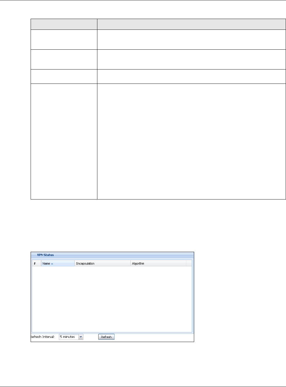
Chapter 5 Dashboard
USG20(W)-VPN Series User’s Guide
86
5.2.3 VPN Status Screen
Click on VPN Status link to look at the VPN tunnels that are currently established. The following
screen will show.
Figure 74 Dashboard > System Status > VPN Status
This table describes the fields in the above screen.
DHCP Table Click this to look at the IP addresses currently assigned to the USG’s DHCP
clients and the IP addresses reserved for specific MAC addresses. See Section
5.2.4 on page 87.
Current Login User This field displays the user name used to log in to the current session, the
amount of reauthentication time remaining, and the amount of lease time
remaining.
Number of Login Users This field displays the number of users currently logged in to the USG. Click the
icon to pop-open a list of the users who are currently logged in to the USG.
Boot Status This field displays details about the USG’s startup state.
OK - The USG started up successfully.
Firmware update OK - A firmware update was successful.
Problematic configuration after firmware update - The application of the
configuration failed after a firmware upgrade.
System default configuration - The USG successfully applied the system
default configuration. This occurs when the USG starts for the first time or you
intentionally reset the USG to the system default settings.
Fallback to lastgood configuration - The USG was unable to apply the
startup-config.conf configuration file and fell back to the lastgood.conf
configuration file.
Fallback to system default configuration - The USG was unable to apply the
lastgood.conf configuration file and fell back to the system default configuration
file (system-default.conf).
Booting in progress - The USG is still applying the system configuration.
Table 18 Dashboard > System Status
LABEL DESCRIPTION
Chapter 5 Dashboard
USG20(W)-VPN Series User’s Guide
87
Table 19 Dashboard > System Status > VPN Status
ZyXEL VPN Client Product Page
5.2.4 DHCP Table Screen
Click on the DHCP Table link to look at the IP addresses currently assigned to DHCP clients and the
IP addresses reserved for specific MAC addresses. The following screen will show.
LABLE DESCRIPTION
# This field is a sequential value, and it is not associated with a specific SA.
Name This field displays the name of the IPSec SA.
Encapsulation This field displays how the IPSec SA is encapsulated.
Algorithm This field displays the encryption and authentication algorithms used in the SA.
Refresh Interval Select how often you want this window to be updated automatically.
Refresh Click this to update the information in the window right away.
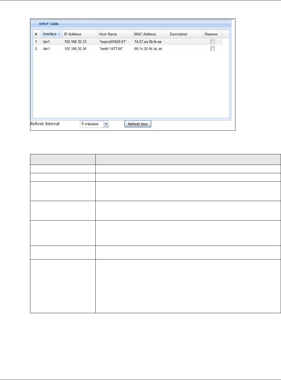
Chapter 5 Dashboard
USG20(W)-VPN Series User’s Guide
88
Figure 75 Dashboard > System Status > DHCP Table
This table describes the fields in the above screen.
5.2.5 Number of Login Users Screen
Click the Number of Login Users link to see the following screen.
Table 20 Dashboard > System Status > DHCP Table
LABEL DESCRIPTION
# This field is a sequential value, and it is not associated with a specific entry.
Interface This field identifies the interface that assigned an IP address to a DHCP client.
IP Address This field displays the IP address currently assigned to a DHCP client or reserved
for a specific MAC address. Click the column’s heading cell to sort the table
entries by IP address. Click the heading cell again to reverse the sort order.
Host Name This field displays the name used to identify this device on the network (the
computer name). The USG learns these from the DHCP client requests. “None”
shows here for a static DHCP entry.
MAC Address This field displays the MAC address to which the IP address is currently assigned
or for which the IP address is reserved. Click the column’s heading cell to sort
the table entries by MAC address. Click the heading cell again to reverse the sort
order.
Description For a static DHCP entry, the host name or the description you configured shows
here. This field is blank for dynamic DHCP entries.
Reserve If this field is selected, this entry is a static DHCP entry. The IP address is
reserved for the MAC address.
If this field is clear, this entry is a dynamic DHCP entry. The IP address is
assigned to a DHCP client.
To create a static DHCP entry using an existing dynamic DHCP entry, select this
field, and then click Apply.
To remove a static DHCP entry, clear this field, and then click Apply.
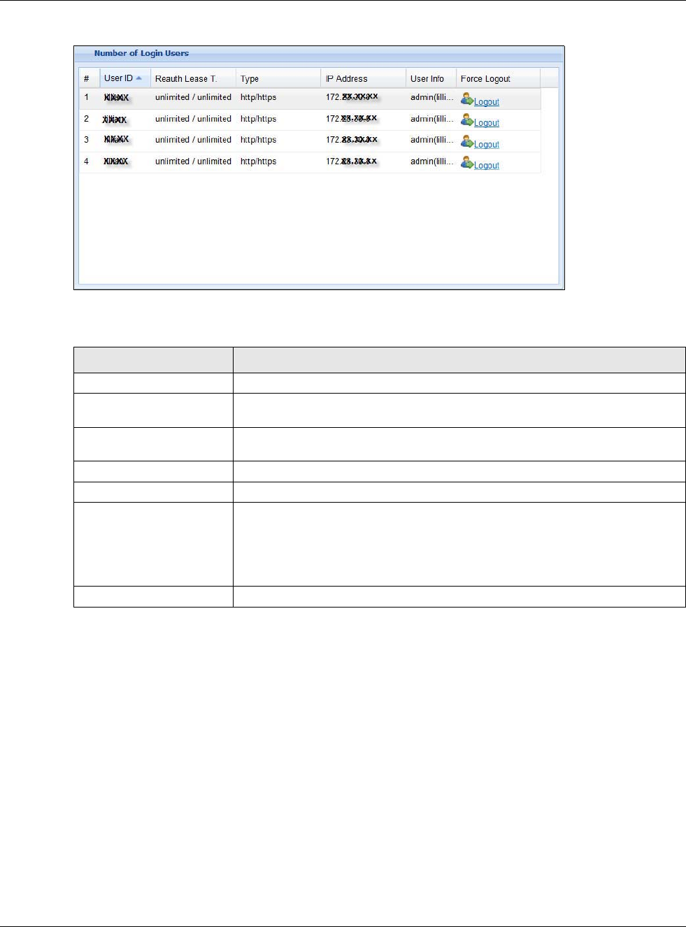
Chapter 5 Dashboard
USG20(W)-VPN Series User’s Guide
89
Figure 76 Dashboard > System Status > Number of Login Users
This table describes the fields in the above screen.
5.2.6 System Resources Screen
Hover your mouse over an item and click the arrow on the right to see more details on that
resource.
Table 21 Dashboard > System Status > Number of Login Users
LABEL DESCRIPTION
# This field is a sequential value and is not associated with any entry.
User ID This field displays the user name of each user who is currently logged in to the
USG.
Reauth Lease T. This field displays the amount of reauthentication time remaining and the
amount of lease time remaining for each user.
Type This field displays the way the user logged in to the USG.
IP address This field displays the IP address of the computer used to log in to the USG.
User Info This field displays the types of user accounts the USG uses. If the user type is
ext-user (external user), this field will show its external-group information
when you move your mouse over it.
If the external user matches two external-group objects, both external-group
object names will be shown.
Force Logout Click this icon to end a user’s session.
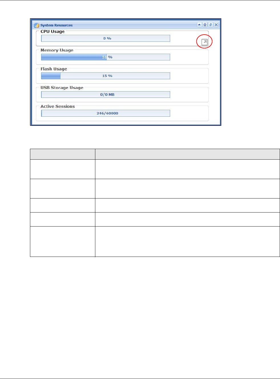
Chapter 5 Dashboard
USG20(W)-VPN Series User’s Guide
90
Figure 77 Dashboard > System Resources
This table describes the fields in the above screen.
5.2.7 CPU Usage Screen
Use the below screen to look at a chart of the USG’s recent CPU usage. To access this screen, click
CPU Usage in the dashboard.
Table 22 .Dashboard > System Resources
LABEL DESCRIPTION
CPU Usage This field displays what percentage of the USG’s processing capability is
currently being used. Hover your cursor over this field to display the Show CPU
Usage icon that takes you to a chart of the USG’s recent CPU usage.
Memory Usage This field displays what percentage of the USG’s RAM is currently being used.
Hover your cursor over this field to display the Show Memory Usage icon that
takes you to a chart of the USG’s recent memory usage.
Flash Usage This field displays what percentage of the USG’s onboard flash memory is
currently being used.
USB Storage Usage This field shows how much storage in the USB device connected to the USG is in
use.
Active Sessions This field shows how many sessions, established and non-established, that pass
through/from/to/within the USG. Hover your cursor over this field to display
icons. Click the Detail icon to go to the Session Monitor screen to see details
about the active sessions. Click the Show Active Sessions icon to display a
chart of USG’s recent session usage.
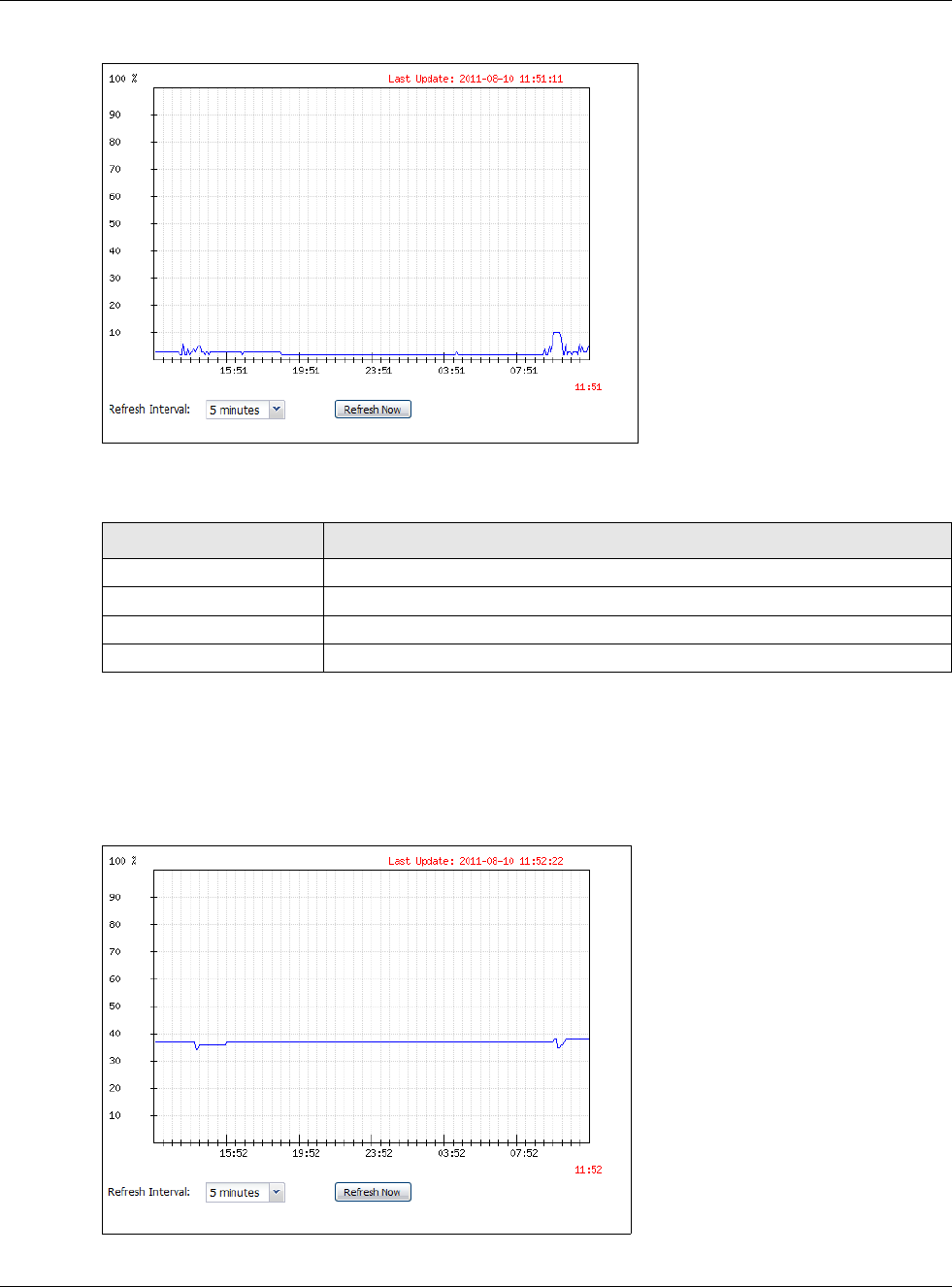
Chapter 5 Dashboard
USG20(W)-VPN Series User’s Guide
91
Figure 78 Dashboard > CPU Usage screen
This table describes the fields in the above screen.
5.2.8 Memory Usage Screen
Use the below screen to look at a chart of the USG’s recent memory (RAM) usage. To access this
screen, click Memory Usage in the dashboard.
Figure 79 Dashboard > Memory Usage screen
Table 23 Dashboard > CPU Usage
LABEL DESCRIPTION
The y-axis represents the percentage of CPU usage.
The x-axis shows the time period over which the CPU usage occurred
Refresh Interval Enter how often you want this window to be automatically updated.
Refresh Now Click this to update the information in the window right away.
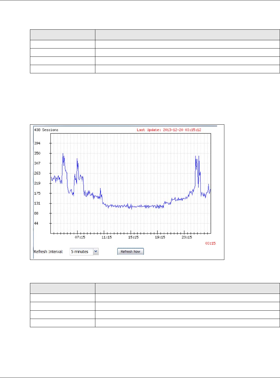
Chapter 5 Dashboard
USG20(W)-VPN Series User’s Guide
92
This table describes the fields in the above screen.
5.2.9 Active Session Screen
To see the details of Active Sessions, move the cursor to the far right of the Active Sessions box and
the Detail and the Show Active Session icons appear. Click the Show Active Session icon.
Figure 80 Dashboard > Active Sessions > Show Active Session
This table describes the fields in the above screen.
Table 24 Dashboard > Memory Usage screen.
LABEL DESCRIPTION
The y-axis represents the percentage of RAM usage.
The x-axis shows the time period over which the RAM usage occurred
Refresh Interval Enter how often you want this window to be automatically updated.
Refresh Now Click this to update the information in the window right away.
Table 25 Dashboard > Active Sessions > Show Active Session
Sessions The y-axis represents the number of session.
The x-axis shows the time period over which the session usage occurred
Refresh Interval Enter how often you want this window to be automatically updated.
Refresh Now Click this to update the information in the window right away.
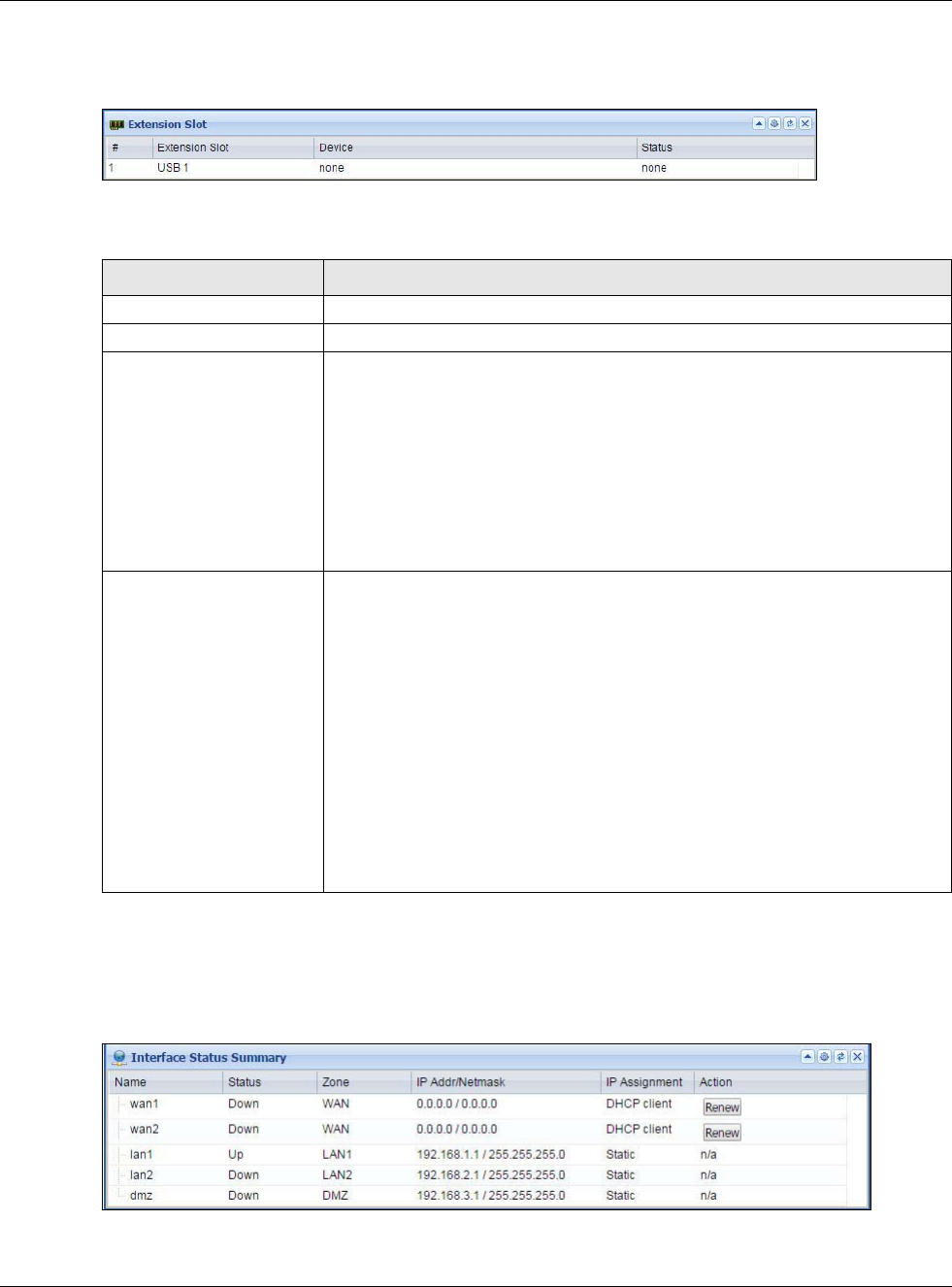
Chapter 5 Dashboard
USG20(W)-VPN Series User’s Guide
93
5.2.10 Extension Slot Screen
Figure 81 Dashboard > Extension Slot
This table describes the fields in the above screen.
5.2.11 Interface Status Summary Screen
Interfaces per USG model vary.
Figure 82 Dashboard > Interface Status Summary
Table 26 Dashboard > Extension Slot
LABEL DESCRIPTION
#
Extension Slot This field displays the name of each extension slot.
Device This field displays the name of the device connected to the extension slot (or
none if no device is detected). For an installed SEM (Security Extension Module)
card, this field displays what kind of SEM card is installed.
SEM-VPN - The VPN accelerator. The SEM-VPN provides 500 Mbps VPN
throughput, 2,000 IPSec VPN tunnels, and 750 SSL VPN users.
SEM-DUAL - accelerator for both VPN and UTM. The SEM-DUAL provides the
benefits of the SEM-VPN.
USB Flash Drive - Indicates a connected USB storage device and the drive’s
storage capacity.
Status The status for an installed WLAN card is none. For cellular (mobile broadband)
interfaces, see Section 6.10 on page 112 for the status that can appear. For an
installed SEM (Security Extension Module) card, this field displays one of the
following:
Active - The SEM card is working properly.
Ready to activate - The SEM was inserted while the USG was operating.
Restart the USG to use the SEM.
Driver load failed - An error occurred during the USG’s attempt to activate the
SEM card. Make sure the SEM is installed properly and the thumbscrews are
tightened. If this status still displays, contact your vendor.
Ready - A USB storage device connected to the USG is ready for the USG to use.
Unused - The USG is unable to mount a USB storage device connected to the
USG.

Chapter 5 Dashboard
USG20(W)-VPN Series User’s Guide
94
This table describes the fields in the above screen.
5.2.12 Secured Service Status Screen
This part shows what security services are available and enabled.
Table 27 Dashboard > Interface Status Summary
LABEL DESCRIPTION
Name This field displays the name of each interface.
Status This field displays the current status of each interface. The possible values depend on
what type of interface it is.
For Ethernet interfaces:
Inactive - The Ethernet interface is disabled.
Down - The Ethernet interface does not have any physical ports associated with it or
the Ethernet interface is enabled but not connected.
Speed / Duplex - The Ethernet interface is enabled and connected. This field displays
the port speed and duplex setting (Full or Half).
For cellular (mobile broadband) interfaces, see Section 6.10 on page 112 for the status
that can appear.
For the auxiliary interface:
Inactive - The auxiliary interface is disabled.
Connected - The auxiliary interface is enabled and connected.
Disconnected - The auxiliary interface is not connected.
For PPP interfaces:
Connected - The PPP interface is connected.
Disconnected - The PPP interface is not connected.
If the PPP interface is disabled, it does not appear in the list.
For WLAN interfaces:
Up - The WLAN interface is enabled.
Down - The WLAN interface is disabled.
Zone This field displays the zone to which the interface is currently assigned.
IP Addr/Netmask This field displays the current IP address and subnet mask assigned to the interface. If
the IP address is 0.0.0.0/0.0.0.0, the interface is disabled or did not receive an IP
address and subnet mask via DHCP.
If this interface is a member of an active virtual router, this field displays the IP
address it is currently using. This is either the static IP address of the interface (if it is
the master) or the management IP address (if it is a backup).
IP Assignment This field displays the interface’s IP assignment. It will show DHCP or Static.
Action Use this field to get or to update the IP address for the interface.
Click Renew to send a new DHCP request to a DHCP server.
Click the Connect icon to have the USG try to connect a PPPoE/PPTP interface. If the
interface cannot use one of these ways to get or to update its IP address, this field
displays n/a.
Click the Disconnect icon to stop a PPPoE/PPTP connection.
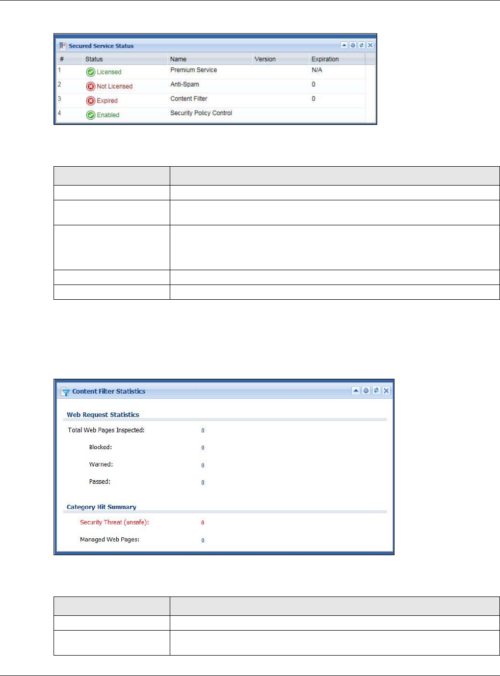
Chapter 5 Dashboard
USG20(W)-VPN Series User’s Guide
95
Figure 83 Dashboard > Secured Service Status
This table describes the fields in the above screen.
5.2.13 Content Filter Statistics Screen
Configure Configuration > UTM Profile > Content Filter and then view results here.
Figure 84 Dashboard > Content Filter Statistics
This table describes the fields in the above screen.
Table 28 Dashboard > Secured Service Status
LABEL DESCRIPTION
# This field is a sequential value, and it is not associated with a specific status.
Status This field displays the status of the USG’s security services. It will show these
types of status: Licensed, Unlicensed, Disabled or Enabled.
Name This field displays the name of security services supported by this model. Status
will show Licensed for Premium Service after you register the device at
myZyXEL.com. You can then activate security service licenses such as Anti-
Spam, Content Filter and so on.
Version This field displays the version number of the services.
Expiration This field displays the number of days remaining before the license expires.
Table 29 Dashboard > Content Filter Statistics
LABEL DESCRIPTION
Web Request Statistics
Total Web Pages
Inspected This is the number of web pages the USG has checked to see whether they
belong to the categories you selected in the content filter screen.
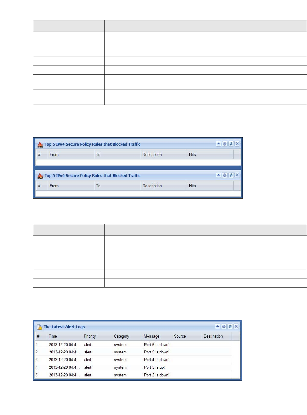
Chapter 5 Dashboard
USG20(W)-VPN Series User’s Guide
96
5.2.14 Top 5 IPv4/IPv6 Security Policy Rules that Blocked Traffic Screen
Figure 85 Dashboard > Top 5 IPv4/IPv6 Security Policy Rules that Blocked Traffic
This table describes the fields in the above screen.
5.2.15 The Latest Alert Logs Screen
Figure 86 Dashboard > The Latest Alert Logs
Blocked This is the number of web pages that the USG blocked access.
Warned This is the number of web pages for which the USG has displayed a warning
message to the access requesters.
Passed This is the number of web pages that the USG allowed access.
Category Hit Summary
Security Threat
(unsafe) This is the number of requested web pages that belong to the unsafe categories
you have selected in the content filter screen.
Managed Web pages This is the number of requested web pages that belong to the managed
categories you have selected in the content filter screen.
Table 29 Dashboard > Content Filter Statistics
LABEL DESCRIPTION
Table 30 Dashboard > Top 5 IPv4/IPv6 Security Policy Rules that Blocked Traffic
LABEL DESCRIPTION
# This is the entry’s rank in the list of the most commonly triggered security
policies.
From This shows the zone packets came from that the triggered security policy.
To This shows the zone packets went to that the triggered security policy.
Description This field displays the descriptive name (if any) of the triggered security policy.
Hits This field displays how many times the security policy was triggered.
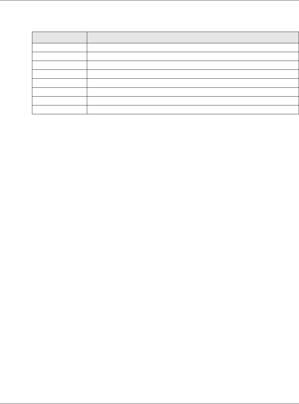
Chapter 5 Dashboard
USG20(W)-VPN Series User’s Guide
97
This table describes the fields in the above screen.
Table 31 Dashboard > The Latest Alert Logs
LABEL DESCRIPTION
# This is the entry’s rank in the list of alert logs.
Time This field displays the date and time the log was created.
Priority This field displays the severity of the log.
Category This field displays the type of log generated.
Message This field displays the actual log message.
Source This field displays the source address (if any) in the packet that generated the log.
Destination This field displays the destination address (if any) in the packet that generated the log.
Source Interface This field displays the incoming interface of the packet that generated the log.

98
PART II
Technical Reference

99

USG20(W)-VPN Series User’s Guide
100
CHAPTER 6
Monitor
6.1 Overview
Use the Monitor screens to check status and statistics information.
6.1.1 What You Can Do in this Chapter
Use the Monitor screens for the following.
•Use the System Status > Port Statistics screen (see Section 6.2 on page 101) to look at
packet statistics for each physical port.
•Use the System Status > Port Statistics > Graph View screen (see Section 6.2 on page 101)
to look at a line graph of packet statistics for each physical port.
•Use the System Status > Interface Status screen (Section 6.3 on page 103) to see all of the
USG’s interfaces and their packet statistics.
•Use the System Status > Traffic Statistics screen (see Section 6.4 on page 105) to start or
stop data collection and view statistics.
•Use the System Status > Session Monitor screen (see Section 6.5 on page 108) to view
sessions by user or service.
•Use the System Status > IGMP Statistics screen (see Section 6.6 on page 109) to view
multicasting details.
•Use the System Status > DDNS Status screen (see Section 6.7 on page 110) to view the
status of the USG’s DDNS domain names.
•Use the System Status > IP/MAC Binding screen (Section 6.8 on page 111) to view a list of
devices that have received an IP address from USG interfaces with IP/MAC binding enabled.
•Use the System Status > Login Users screen (Section 6.9 on page 111) to look at a list of the
users currently logged into the USG.
•Use the System Status > Cellular Status screen (Section 6.10 on page 112) to check your
mobile broadband connection status.
•Use the System Status > UPnP Port Status screen (see Section 6.11 on page 114) to look at
a list of the NAT port mapping rules that UPnP creates on the USG.
•Use the System Status > USB Storage screen (Section 6.12 on page 115) to view information
about a connected USB storage device.
•Use the System Status > Ethernet Neighbor screen (Section 6.13 on page 116) to view and
manage the USG’s neighboring devices via Layer Link Discovery Protocol (LLDP).
•Use the Wireless > AP Information screen (Section 6.14.1 on page 117) to view information
on connected APs.
•Use the Wireless > Station Info screen (Section 6.14.3 on page 120) to view information on
connected wireless stations.
•Use the Wireless > Detected Device screen (Section 6.14.3 on page 120) to view information
about suspected rogue APs.
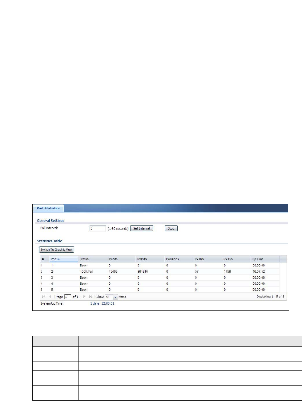
Chapter 6 Monitor
USG20(W)-VPN Series User’s Guide
101
•Use the VPN Monitor > IPSec screen (Section 6.15 on page 122) to display and manage active
IPSec SAs.
•Use the VPN Monitor > SSL screen (see Section 6.16 on page 123) to list the users currently
logged into the VPN SSL client portal. You can also log out individual users and delete related
session information.
•Use the VPN Monitor > L2TP over IPSec screen (see Section 6.17 on page 124) to display and
manage the USG’s connected L2TP VPN sessions.
•Use the UTM Statistics > Content Filter screen (Section 6.18 on page 125) to start or stop
data collection and view content filter statistics.
•Use the UTM Statistics > Anti-Spam screen (Section 6.19 on page 127) to start or stop data
collection and view spam statistics.
•Use the UTM Statistics > Anti-Spam > Status screen (Section 6.19.2 on page 129) to see
how many mail sessions the USG is currently checking and DNSBL statistics.
•Use the Log screens (Section 6.20 on page 130) to view the USG’s current log messages. You
can change the way the log is displayed, you can e-mail the log, and you can also clear the log in
this screen.
6.2 The Port Statistics Screen
Use this screen to look at packet statistics for each Gigabit Ethernet port. To access this screen,
click Monitor > System Status > Port Statistics.
Figure 87 Monitor > System Status > Port Statistics
The following table describes the labels in this screen.
Table 32 Monitor > System Status > Port Statistics
LABEL DESCRIPTION
Poll Interval Enter how often you want this window to be updated automatically, and click Set
Interval.
Set Interval Click this to set the Poll Interval the screen uses.
Stop Click this to stop the window from updating automatically. You can start it again by setting
the Poll Interval and clicking Set Interval.
Switch to
Graphic View
Click this to display the port statistics as a line graph.
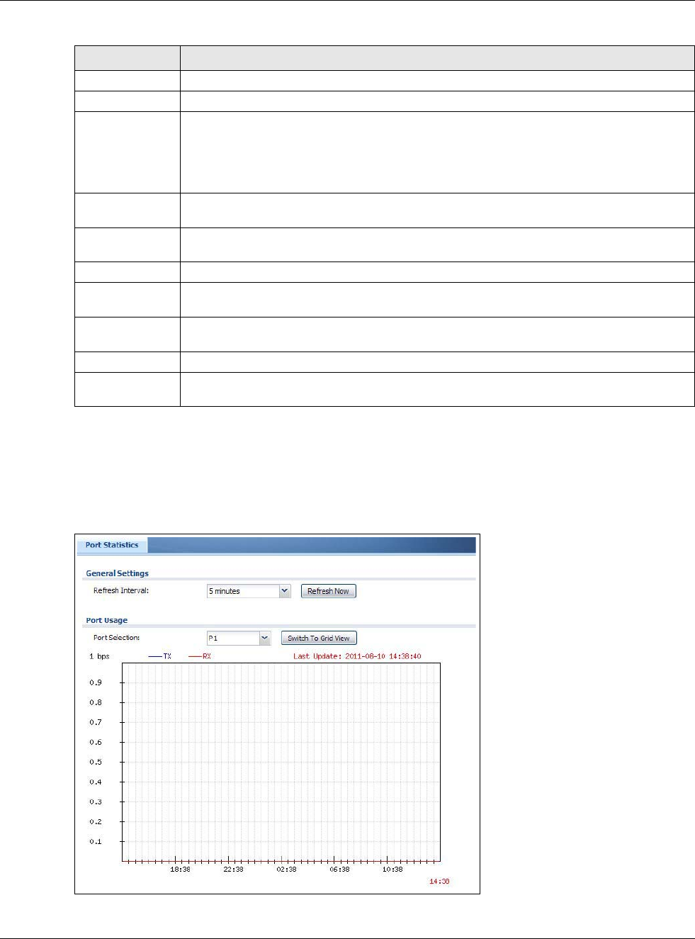
Chapter 6 Monitor
USG20(W)-VPN Series User’s Guide
102
6.2.1 The Port Statistics Graph Screen
Use this screen to look at a line graph of packet statistics for each physical port. To access this
screen, click Port Statistics in the Status screen and then the Switch to Graphic View Button.
Figure 88 Monitor > System Status > Port Statistics > Switch to Graphic View
# This field is a sequential value, and it is not associated with a specific port.
Port This field displays the physical port number.
Status This field displays the current status of the physical port.
Down - The physical port is not connected.
Speed / Duplex - The physical port is connected. This field displays the port speed and
duplex setting (Full or Half).
TxPkts This field displays the number of packets transmitted from the USG on the physical port
since it was last connected.
RxPkts This field displays the number of packets received by the USG on the physical port since it
was last connected.
Collisions This field displays the number of collisions on the physical port since it was last connected.
Tx B/s This field displays the transmission speed, in bytes per second, on the physical port in the
one-second interval before the screen updated.
Rx B/s This field displays the reception speed, in bytes per second, on the physical port in the
one-second interval before the screen updated.
Up Time This field displays how long the physical port has been connected.
System Up Time This field displays how long the USG has been running since it last restarted or was turned
on.
Table 32 Monitor > System Status > Port Statistics (continued)
LABEL DESCRIPTION
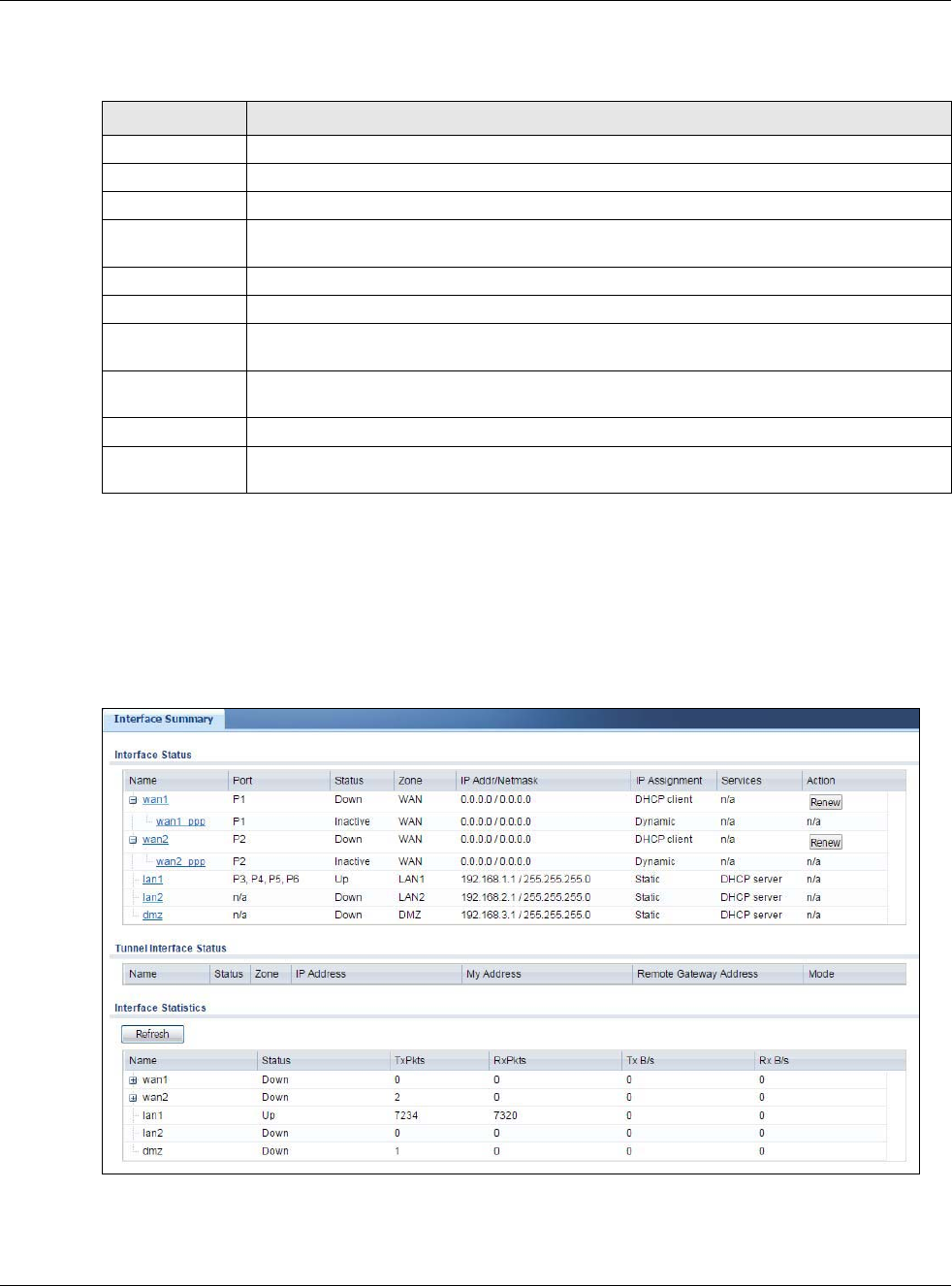
Chapter 6 Monitor
USG20(W)-VPN Series User’s Guide
103
The following table describes the labels in this screen.
6.3 Interface Status Screen
This screen lists all of the USG’s interfaces and gives packet statistics for them. Click Monitor >
System Status > Interface Status to access this screen.
Figure 89 Monitor > System Status > Interface Status
Table 33 Monitor > System Status > Port Statistics > Switch to Graphic View
LABEL DESCRIPTION
Refresh Interval Enter how often you want this window to be automatically updated.
Refresh Now Click this to update the information in the window right away.
Port Selection Select the number of the physical port for which you want to display graphics.
Switch to Grid
View
Click this to display the port statistics as a table.
bps The y-axis represents the speed of transmission or reception.
time The x-axis shows the time period over which the transmission or reception occurred
TX This line represents traffic transmitted from the USG on the physical port since it was last
connected.
RX This line represents the traffic received by the USG on the physical port since it was last
connected.
Last Update This field displays the date and time the information in the window was last updated.
System Up Time This field displays how long the USG has been running since it last restarted or was turned
on.

Chapter 6 Monitor
USG20(W)-VPN Series User’s Guide
104
Each field is described in the following table.
Table 34 Monitor > System Status > Interface Status
LABEL DESCRIPTION
Interface Status If an Ethernet interface does not have any physical ports associated with it, its entry is
displayed in light gray text.
Name This field displays the name of each interface. If there is an Expand icon (plus-sign) next
to the name, click this to look at the status of virtual interfaces on top of this interface.
Port This field displays the physical port number.
Status This field displays the current status of each interface. The possible values depend on what
type of interface it is.
For Ethernet interfaces:
•Inactive - The Ethernet interface is disabled.
•Down - The Ethernet interface does not have any physical ports associated with it or
the Ethernet interface is enabled but not connected.
•Speed / Duplex - The Ethernet interface is enabled and connected. This field displays
the port speed and duplex setting (Full or Half).
For cellular (mobile broadband) interfaces, see Section 6.12 on page 115 the Web Help for
the status that can appear.
For the auxiliary interface:
•Inactive - The auxiliary interface is disabled.
•Connected - The auxiliary interface is enabled and connected.
•Disconnected - The auxiliary interface is not connected.
For virtual interfaces, this field always displays Up. If the virtual interface is disabled, it
does not appear in the list.
For VLAN and bridge interfaces, this field always displays Up. If the VLAN or bridge
interface is disabled, it does not appear in the list.
For PPP interfaces:
•Connected - The PPP interface is connected.
•Disconnected - The PPP interface is not connected.
If the PPP interface is disabled, it does not appear in the list.
For WLAN interfaces:
•Up - The WLAN interface is enabled.
•Down - The WLAN interface is disabled.
Zone This field displays the zone to which the interface is assigned.
IP Addr/Netmask This field displays the current IP address and subnet mask assigned to the interface. If the
IP address and subnet mask are 0.0.0.0, the interface is disabled or did not receive an IP
address and subnet mask via DHCP.
If this interface is a member of an active virtual router, this field displays the IP address it
is currently using. This is either the static IP address of the interface (if it is the master) or
the management IP address (if it is a backup).
IP Assignment This field displays how the interface gets its IP address.
•Static - This interface has a static IP address.
•DHCP Client - This interface gets its IP address from a DHCP server.
Services This field lists which services the interface provides to the network. Examples include
DHCP relay, DHCP server, DDNS, RIP, and OSPF. This field displays n/a if the interface
does not provide any services to the network.

Chapter 6 Monitor
USG20(W)-VPN Series User’s Guide
105
6.4 The Traffic Statistics Screen
Click Monitor > System Status > Traffic Statistics to display the Traffic Statistics screen. This
screen provides basic information about the following for example:
• Most-visited Web sites and the number of times each one was visited. This count may not be
accurate in some cases because the USG counts HTTP GET packets. Please see Table 35 on page
106 for more information.
• Most-used protocols or service ports and the amount of traffic on each one
Action Use this field to get or to update the IP address for the interface. Click Renew to send a
new DHCP request to a DHCP server. Click Connect to try to connect a PPPoE/PPTP
interface. If the interface cannot use one of these ways to get or to update its IP address,
this field displays n/a.
Tunnel Interface
Status
This displays the details of the USG’s configured tunnel interfaces.
Name This field displays the name of the interface.
Status The activate (light bulb) icon is lit when the entry is active and dimmed when the entry is
inactive.
Zone This field displays the zone to which the interface is assigned.
IP Address This is the IP address of the interface. If the interface is active (and connected), the USG
tunnels local traffic sent to this IP address to the Remote Gateway Address.
My Address This is the interface or IP address uses to identify itself to the remote gateway. The USG
uses this as the source for the packets it tunnels to the remote gateway.
Remote Gateway
Address
This is the IP address or domain name of the remote gateway to which this interface
tunnels traffic.
Mode This field displays the tunnel mode that you are using.
Interface
Statistics
This table provides packet statistics for each interface.
Refresh Click this button to update the information in the screen.
Name This field displays the name of each interface. If there is a Expand icon (plus-sign) next to
the name, click this to look at the statistics for virtual interfaces on top of this interface.
Status This field displays the current status of the interface.
•Down - The interface is not connected.
•Speed / Duplex - The interface is connected. This field displays the port speed and
duplex setting (Full or Half).
This field displays Connected and the accumulated connection time (hh:mm:ss) when the
PPP interface is connected.
TxPkts This field displays the number of packets transmitted from the USG on the interface since
it was last connected.
RxPkts This field displays the number of packets received by the USG on the interface since it was
last connected.
Tx B/s This field displays the transmission speed, in bytes per second, on the interface in the one-
second interval before the screen updated.
Rx B/s This field displays the reception speed, in bytes per second, on the interface in the one-
second interval before the screen updated.
Table 34 Monitor > System Status > Interface Status (continued)
LABEL DESCRIPTION
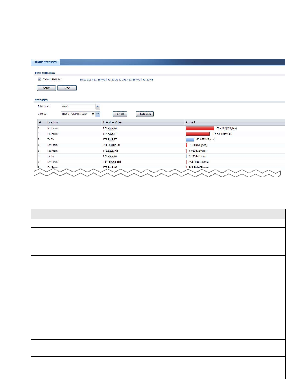
Chapter 6 Monitor
USG20(W)-VPN Series User’s Guide
106
• LAN IP with heaviest traffic and how much traffic has been sent to and from each one
You use the Traffic Statistics screen to tell the USG when to start and when to stop collecting
information for these reports. You cannot schedule data collection; you have to start and stop it
manually in the Traffic Statistics screen.
Figure 90 Monitor > System Status > Traffic Statistics
There is a limit on the number of records shown in the report. Please see Table 36 on page 107 for
more information. The following table describes the labels in this screen.
Table 35 Monitor > System Status > Traffic Statistics
LABEL DESCRIPTION
Data Collection
Collect Statistics Select this to have the USG collect data for the report. If the USG has already been
collecting data, the collection period displays to the right. The progress is not tracked here
real-time, but you can click the Refresh button to update it.
Apply Click Apply to save your changes back to the USG.
Reset Click Reset to return the screen to its last-saved settings.
Statistics
Interface Select the interface from which to collect information. You can collect information from
Ethernet, VLAN, bridge and PPPoE/PPTP interfaces.
Sort By Select the type of report to display. Choices are:
•Host IP Address/User - displays the IP addresses or users with the most traffic and
how much traffic has been sent to and from each one.
•Service/Port - displays the most-used protocols or service ports and the amount of
traffic for each one.
•Web Site Hits - displays the most-visited Web sites and how many times each one has
been visited.
Each type of report has different information in the report (below).
Refresh Click this button to update the report display.
Flush Data Click this button to discard all of the screen’s statistics and update the report display.
These fields are available when the Traffic Type is Host IP Address/User.
# This field is the rank of each record. The IP addresses and users are sorted by the amount
of traffic.
Chapter 6 Monitor
USG20(W)-VPN Series User’s Guide
107
The following table displays the maximum number of records shown in the report, the byte count
limit, and the hit count limit.
Direction This field indicates whether the IP address or user is sending or receiving traffic.
•Ingress- traffic is coming from the IP address or user to the USG.
•Egress - traffic is going from the USG to the IP address or user.
IP Address/User This field displays the IP address or user in this record. The maximum number of IP
addresses or users in this report is indicated in Table 36 on page 107.
Amount This field displays how much traffic was sent or received from the indicated IP address or
user. If the Direction is Ingress, a red bar is displayed; if the Direction is Egress, a
blue bar is displayed. The unit of measure is bytes, Kbytes, Mbytes or Gbytes, depending
on the amount of traffic for the particular IP address or user. The count starts over at zero
if the number of bytes passes the byte count limit. See Table 36 on page 107.
These fields are available when the Traffic Type is Service/Port.
# This field is the rank of each record. The protocols and service ports are sorted by the
amount of traffic.
Service/Port This field displays the service and port in this record. The maximum number of services
and service ports in this report is indicated in Table 36 on page 107.
Protocol This field indicates what protocol the service was using.
Direction This field indicates whether the indicated protocol or service port is sending or receiving
traffic.
•Ingress - traffic is coming into the router through the interface
•Egress - traffic is going out from the router through the interface
Amount This field displays how much traffic was sent or received from the indicated service / port.
If the Direction is Ingress, a red bar is displayed; if the Direction is Egress, a blue bar
is displayed. The unit of measure is bytes, Kbytes, Mbytes, Gbytes, or Tbytes, depending
on the amount of traffic for the particular protocol or service port. The count starts over at
zero if the number of bytes passes the byte count limit. See Table 36 on page 107.
These fields are available when the Traffic Type is Web Site Hits.
# This field is the rank of each record. The domain names are sorted by the number of hits.
Web Site This field displays the domain names most often visited. The USG counts each page
viewed on a Web site as another hit. The maximum number of domain names in this report
is indicated in Table 36 on page 107.
Hits This field displays how many hits the Web site received. The USG counts hits by counting
HTTP GET packets. Many Web sites have HTTP GET references to other Web sites, and the
USG counts these as hits too. The count starts over at zero if the number of hits passes
the hit count limit. See Table 36 on page 107.
Table 36 Maximum Values for Reports
LABEL DESCRIPTION
Maximum Number of Records 20
Byte Count Limit 264 bytes; this is just less than 17 million terabytes.
Hit Count Limit 264 hits; this is over 1.8 x 10¹⁹ hits.
Table 35 Monitor > System Status > Traffic Statistics (continued)
LABEL DESCRIPTION
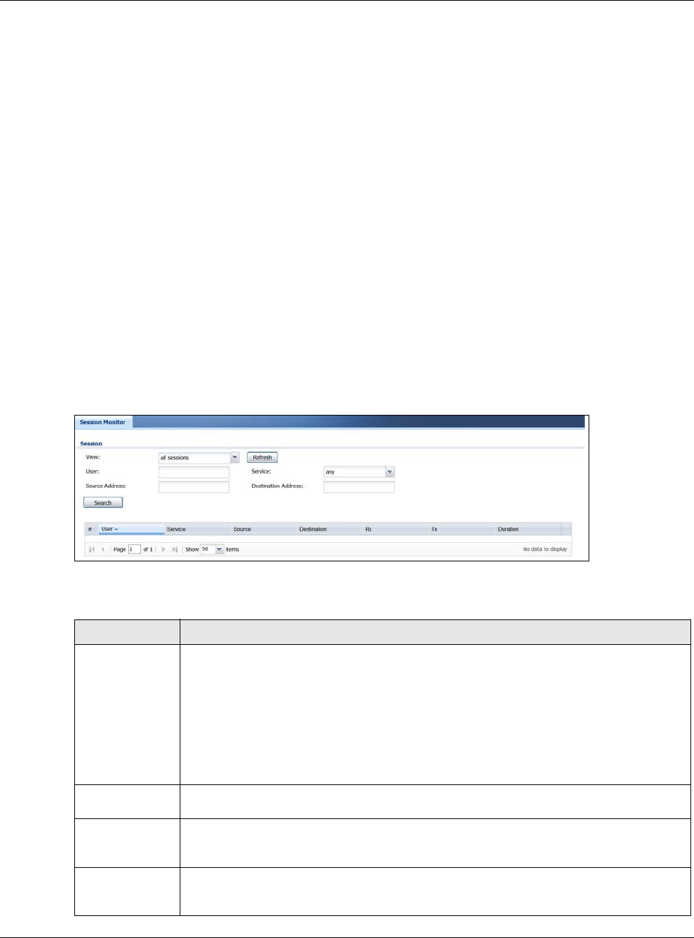
Chapter 6 Monitor
USG20(W)-VPN Series User’s Guide
108
6.5 The Session Monitor Screen
The Session Monitor screen displays all established sessions that pass through the USG for
debugging or statistical analysis. It is not possible to manage sessions in this screen. The following
information is displayed.
• User who started the session
• Protocol or service port used
• Source address
• Destination address
• Number of bytes received (so far)
• Number of bytes transmitted (so far)
• Duration (so far)
You can look at all established sessions that passed through the USG by user, service, source IP
address, or destination IP address. You can also filter the information by user, protocol / service or
service group, source address, and/or destination address and view it by user.
Click Monitor > System Status > Session Monitor to display the following screen.
Figure 91 Monitor > System Status > Session Monitor
The following table describes the labels in this screen.
Table 37 Monitor > System Status > Session Monitor
LABEL DESCRIPTION
View Select how you want the established sessions that passed through the USG to be
displayed. Choices are:
•sessions by users - display all active sessions grouped by user
•sessions by services - display all active sessions grouped by service or protocol
•sessions by source IP - display all active sessions grouped by source IP address
•sessions by destination IP - display all active sessions grouped by destination IP
address
•all sessions - filter the active sessions by the User, Service, Source Address, and
Destination Address, and display each session individually (sorted by user).
Refresh Click this button to update the information on the screen. The screen also refreshes
automatically when you open and close the screen.
The User, Service, Source Address, and Destination Address fields display if you view
all sessions. Select your desired filter criteria and click the Refresh button to filter the list
of sessions.
User This field displays when View is set to all sessions. Type the user whose sessions you
want to view. It is not possible to type part of the user name or use wildcards in this field;
you must enter the whole user name.
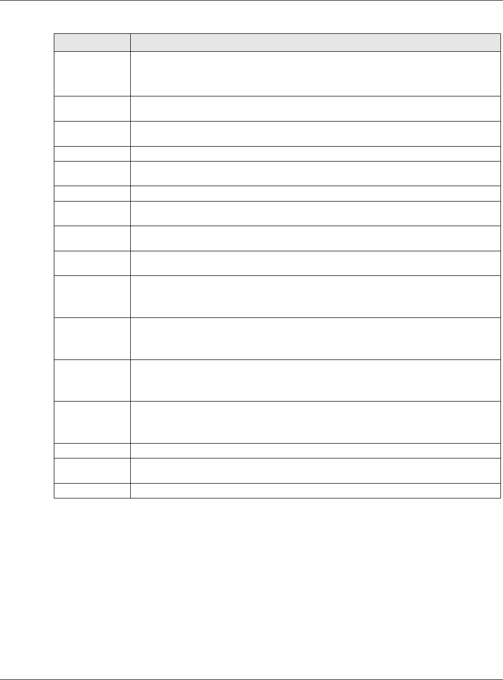
Chapter 6 Monitor
USG20(W)-VPN Series User’s Guide
109
6.6 IGMP Statistics
The Internet Group Management Protocol (IGMP) Statistics is used by USG IP hosts to inform
adjacent router about multicast group memberships. It can also be used for one-to-many
networking applications such as online streaming video and gaming, distribution of company
newsletters, updating address book of mobile computer users in the field allowing more efficient
use of resources when supporting these types of applications. Click Monitor > System Status >
IGMP Statistics to open the following screen.
Service This field displays when View is set to all sessions. Select the service or service group
whose sessions you want to view. The USG identifies the service by comparing the
protocol and destination port of each packet to the protocol and port of each services that
is defined.
Source This field displays when View is set to all sessions. Type the source IP address whose
sessions you want to view. You cannot include the source port.
Destination This field displays when View is set to all sessions. Type the destination IP address
whose sessions you want to view. You cannot include the destination port.
Rx This field displays the amount of information received by the source in the active session.
Tx This field displays the amount of information transmitted by the source in the active
session.
Duration This field displays the length of the active session in seconds.
Active Sessions This is the total number of established sessions that passed through the USG which
matched the search criteria.
Show Select the number of active sessions displayed on each page. You can use the arrow keys
on the right to change pages.
# This field is the rank of each record. The names are sorted by the name of user in active
session. You can use the pull down menu on the right to choose sorting method.
User This field displays the user in each active session.
If you are looking at the sessions by users (or all sessions) report, click + or - to
display or hide details about a user’s sessions.
Service This field displays the protocol used in each active session.
If you are looking at the sessions by services report, click + or - to display or hide
details about a protocol’s sessions.
Source This field displays the source IP address and port in each active session.
If you are looking at the sessions by source IP report, click + or - to display or hide
details about a source IP address’s sessions.
Destination This field displays the destination IP address and port in each active session.
If you are looking at the sessions by destination IP report, click + or - to display or
hide details about a destination IP address’s sessions.
Rx This field displays the amount of information received by the source in the active session.
Tx This field displays the amount of information transmitted by the source in the active
session.
Duration This field displays the length of the active session in seconds.
Table 37 Monitor > System Status > Session Monitor (continued)
LABEL DESCRIPTION
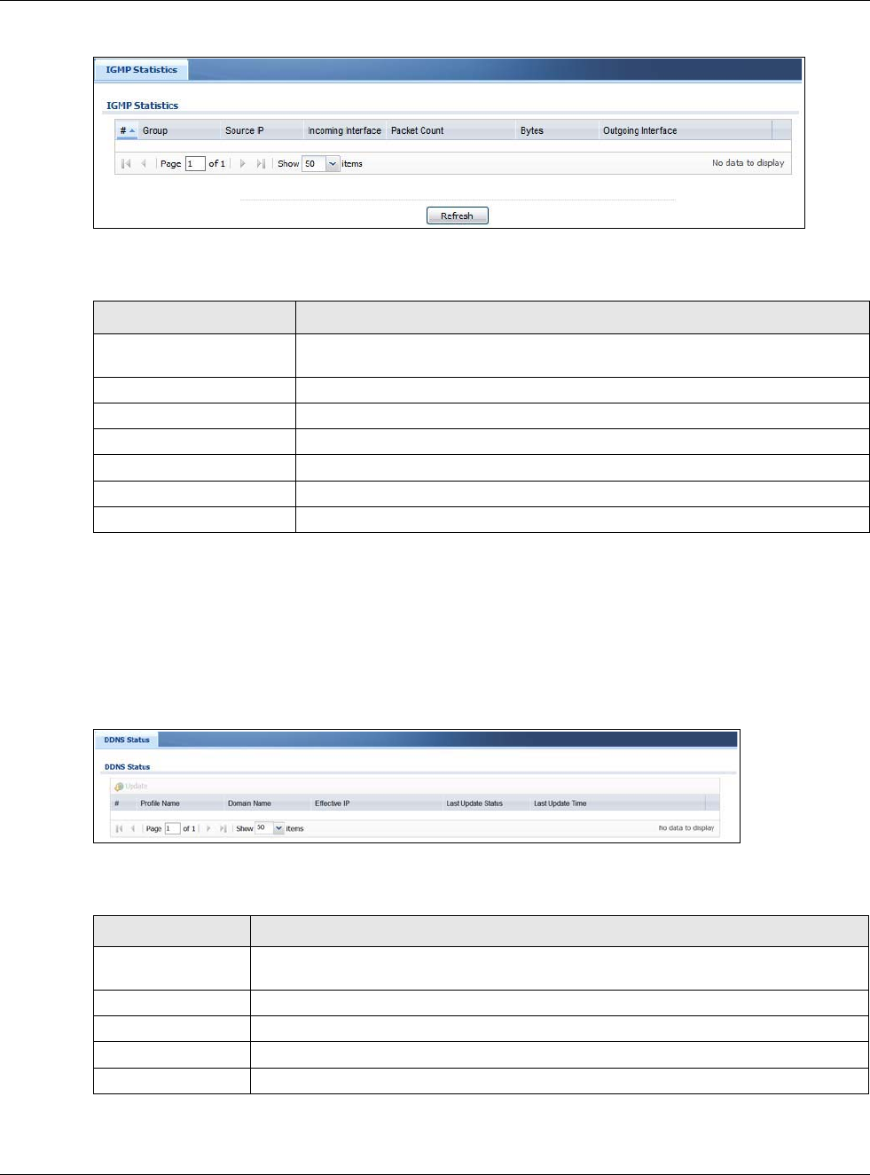
Chapter 6 Monitor
USG20(W)-VPN Series User’s Guide
110
Figure 92 Monitor > System Status > IGMP Statistics
The following table describes the labels in this screen.
6.7 The DDNS Status Screen
The DDNS Status screen shows the status of the USG’s DDNS domain names. Click Monitor >
System Status > DDNS Status to open the following screen.
Figure 93 Monitor > System Status > DDNS Status
The following table describes the labels in this screen.
Table 38 Monitor > System Status > IGMP Statistics
LABEL DESCRIPTION
# This field is a sequential value, and it is not associated with a specific I GMP
Statistics.
Group This field displays the group of devices in the IGMP.
Source IP This field displays the host source IP information of the IGMP.
Incoming Interface This field displays the incoming interface that’s connected on the IGMP.
Packet Count This field displays the packet size of the data being transferred.
Bytes This field displays the size of the data being transferred in Byes.
Outgoing Interface This field displays the outgoing interface that’s connected on the IGMP.
Table 39 Monitor > System Status > DDNS Status
LABEL DESCRIPTION
Update Click this to have the USG update the profile to the DDNS server. The USG attempts to
resolve the IP address for the domain name.
# This field is a sequential value, and it is not associated with a specific DDNS server.
Profile Name This field displays the descriptive profile name for this entry.
Domain Name This field displays each domain name the USG can route.
Effective IP This is the (resolved) IP address of the domain name.
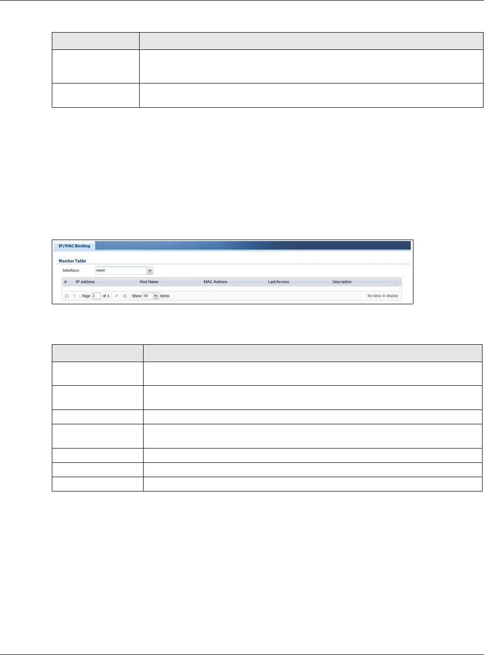
Chapter 6 Monitor
USG20(W)-VPN Series User’s Guide
111
6.8 IP/MAC Binding
Click Monitor > System Status > IP/MAC Binding to open the IP/MAC Binding screen. This
screen lists the devices that have received an IP address from USG interfaces with IP/MAC binding
enabled and have ever established a session with the USG. Devices that have never established a
session with the USG do not display in the list.
Figure 94 Monitor > System Status > IP/MAC Binding
The following table describes the labels in this screen.
6.9 The Login Users Screen
Use this screen to look at a list of the users currently logged into the USG. To access this screen,
click Monitor > System Status > Login Users.
Last Update Status This shows whether the last attempt to resolve the IP address for the domain name
was successful or not. Updating means the USG is currently attempting to resolve the
IP address for the domain name.
Last Update Time This shows when the last attempt to resolve the IP address for the domain name
occurred (in year-month-day hour:minute:second format).
Table 39 Monitor > System Status > DDNS Status (continued)
LABEL DESCRIPTION
Table 40 Monitor > System Status > IP/MAC Binding
LABEL DESCRIPTION
Interface Select a USG interface that has IP/MAC binding enabled to show to which devices it
has assigned an IP address.
#This field is a sequential value, and it is not associated with a specific IP/MAC binding
entry.
IP Address This is the IP address that the USG assigned to a device.
Host Name This field displays the name used to identify this device on the network (the computer
name). The USG learns these from the DHCP client requests.
MAC Address This field displays the MAC address to which the IP address is currently assigned.
Last Access This is when the device last established a session with the USG through this interface.
Description This field displays the description of the IP/MAC binding.
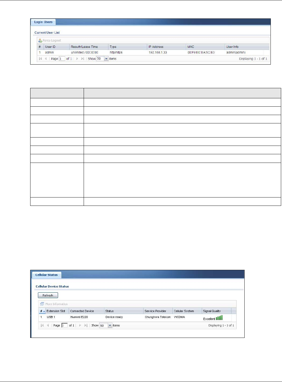
Chapter 6 Monitor
USG20(W)-VPN Series User’s Guide
112
Figure 95 Monitor > System Status > Login Users
The following table describes the labels in this screen.
6.10 Cellular Status Screen
This screen displays your mobile broadband connection status. Click Monitor > System Status >
Cellular Status to display this screen.
Figure 96 Monitor > System Status > Cellular Status
Table 41 Monitor > System Status > Login Users
LABEL DESCRIPTION
Force Logout Select a user ID and click this icon to end a user’s session.
# This field is a sequential value and is not associated with any entry.
User ID This field displays the user name of each user who is currently logged in to the USG.
Reauth Lease T. This field displays the amount of reauthentication time remaining and the amount of
lease time remaining for each user.
Type This field displays the way the user logged in to the USG.
IP Address This field displays the IP address of the computer used to log in to the USG.
MAC This field displays the MAC address of the computer used to log in to the USG.
User Info This field displays the types of user accounts the USG uses. If the user type is ext-
user (external user), this field will show its external-group information when you
move your mouse over it.
If the external user matches two external-group objects, both external-group object
names will be shown.
Refresh Click this button to update the information in the screen.

Chapter 6 Monitor
USG20(W)-VPN Series User’s Guide
113
The following table describes the labels in this screen.
Table 42 Monitor > System Status > Cellular Status
LABEL DESCRIPTION
Refresh Click this button to update the information in the screen.
More Information Click this to display more information on your mobile broadband, such as the signal
strength, IMEA/ESN and IMSI. This is only available when the mobile broadband device
attached and activated on your USG. Refer to Section 6.11 on page 114.
#This field is a sequential value, and it is not associated with any interface.
Extension Slot This field displays where the entry’s cellular card is located.
Connected Device This field displays the model name of the cellular card.
Status • No device - no mobile broadband device is connected to the USG.
•No Service - no mobile broadband network is available in the area; you cannot
connect to the Internet.
•Limited Service - returned by the service provider in cases where the SIM card is
expired, the user failed to pay for the service and so on; you cannot connect to the
Internet.
•Device detected - displays when you connect a mobile broadband device.
•Device error - a mobile broadband device is connected but there is an error.
•Probe device fail - the USG’s test of the mobile broadband device failed.
•Probe device ok - the USG’s test of the mobile broadband device succeeded.
•Init device fail - the USG was not able to initialize the mobile broadband device.
•Init device ok - the USG initialized the mobile broadband card.
•Check lock fail - the USG’s check of whether or not the mobile broadband device is
locked failed.
•Device locked - the mobile broadband device is locked.
•SIM error - there is a SIM card error on the mobile broadband device.
•SIM locked-PUK - the PUK is locked on the mobile broadband device’s SIM card.
•SIM locked-PIN - the PIN is locked on the mobile broadband device’s SIM card.
•Unlock PUK fail - Your attempt to unlock a WCDMA mobile broadband device’s PUK
failed because you entered an incorrect PUK.
•Unlock PIN fail - Your attempt to unlock a WCDMA mobile broadband device’s PIN
failed because you entered an incorrect PIN.
•Unlock device fail - Your attempt to unlock a CDMA2000 mobile broadband device
failed because you entered an incorrect device code.
•Device unlocked - You entered the correct device code and unlocked a CDMA2000
mobile broadband device.
•Get dev-info fail - The USG cannot get cellular device information.
•Get dev-info ok - The USG succeeded in retrieving mobile broadband device
information.
•Searching network - The mobile broadband device is searching for a network.
•Get signal fail - The mobile broadband device cannot get a signal from a network.
•Network found - The mobile broadband device found a network.
•Apply config - The USG is applying your configuration to the mobile broadband
device.
•Inactive - The mobile broadband interface is disabled.
•Active - The mobile broadband interface is enabled.
•Incorrect device - The connected mobile broadband device is not compatible with
the USG.
•Correct device - The USG detected a compatible mobile broadband device.
•Set band fail - Applying your band selection was not successful.
•Set band ok - The USG successfully applied your band selection.
•Set profile fail - Applying your ISP settings was not successful.
•Set profile ok - The USG successfully applied your ISP settings.
•PPP fail - The USG failed to create a PPP connection for the cellular interface.
•Need auth-password - You need to enter the password for the mobile broadband
card in the cellular edit screen.
•Device ready - The USG successfully applied all of your configuration and you can
use the mobile broadband connection.
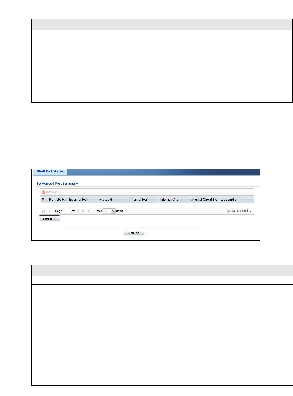
Chapter 6 Monitor
USG20(W)-VPN Series User’s Guide
114
6.11 The UPnP Port Status Screen
Use this screen to look at the NAT port mapping rules that UPnP creates on the USG. To access this
screen, click Monitor > System Status > UPnP Port Status.
Figure 97 Monitor > System Status > UPnP Port Status
The following table describes the labels in this screen.
Service Provider This displays the name of your network service provider. This shows Limited Service if
the service provider has stopped service to the mobile broadband card. For example if
the bill has not been paid or the account has expired.
Cellular System This field displays what type of cellular network the mobile broadband connection is
using. The network type varies depending on the mobile broadband card you inserted
and could be UMTS, UMTS/HSDPA, GPRS or EDGE when you insert a GSM mobile
broadband card, or 1xRTT, EVDO Rev.0 or EVDO Rev.A when you insert a CDMA
mobile broadband card.
Signal Quality This displays the strength of the signal. The signal strength mainly depends on the
antenna output power and the distance between your USG and the service provider’s
base station.
Table 42 Monitor > System Status > Cellular Status (continued)
LABEL DESCRIPTION
Table 43 Monitor > System Status > UPnP Port Status
LABEL DESCRIPTION
Remove Select an entry and click this button to remove it from the list.
# This is the index number of the UPnP-created NAT mapping rule entry.
Remote Host This field displays the source IP address (on the WAN) of inbound IP packets. Since this is
often a wildcard, the field may be blank.
When the field is blank, the USG forwards all traffic sent to the External Port on the
WAN interface to the Internal Client on the Internal Port.
When this field displays an external IP address, the NAT rule has the USG forward
inbound packets to the Internal Client from that IP address only.
External Port This field displays the port number that the USG “listens” on (on the WAN port) for
connection requests destined for the NAT rule’s Internal Port and Internal Client. The
USG forwards incoming packets (from the WAN) with this port number to the Internal
Client on the Internal Port (on the LAN). If the field displays “0”, the USG ignores the
Internal Port value and forwards requests on all external port numbers (that are
otherwise unmapped) to the Internal Client.
Protocol This field displays the protocol of the NAT mapping rule (TCP or UDP).
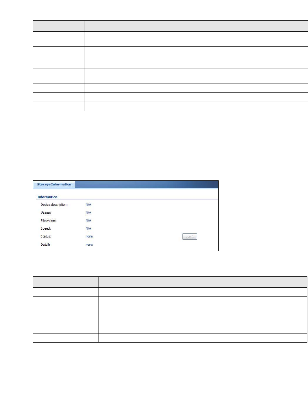
Chapter 6 Monitor
USG20(W)-VPN Series User’s Guide
115
6.12 USB Storage Screen
This screen displays information about a connected USB storage device. Click Monitor > System
Status > USB Storage to display this screen.
Figure 98 Monitor > System Status > USB Storage
The following table describes the labels in this screen.
Internal Port This field displays the port number on the Internal Client to which the USG should
forward incoming connection requests.
Internal Client This field displays the DNS host name or IP address of a client on the LAN. Multiple NAT
clients can use a single port simultaneously if the internal client field is set to
255.255.255.255 for UDP mappings.
Internal Client
Type
This field displays the type of the client application on the LAN.
Description This field displays a text explanation of the NAT mapping rule.
Delete All Click this to remove all mapping rules from the NAT table.
Refresh Click this button to update the information in the screen.
Table 43 Monitor > System Status > UPnP Port Status (continued)
LABEL DESCRIPTION
Table 44 Monitor > System Status > USB Storage
LABEL DESCRIPTION
Device description This is a basic description of the type of USB device.
Usage This field displays how much of the USB storage device’s capacity is currently being
used out of its total capacity and what percentage that makes.
Filesystem This field displays what file system the USB storage device is formatted with. This
field displays Unknown if the file system of the USB storage device is not
supported by the USG, such as NTFS.
Speed This field displays the connection speed the USB storage device supports.
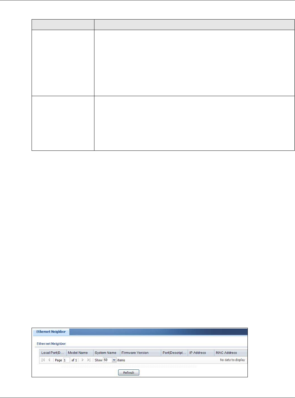
Chapter 6 Monitor
USG20(W)-VPN Series User’s Guide
116
6.13 Ethernet Neighbor Screen
The Ethernet Neighbor screen allows you to view the USG’s neighboring devices in one place.
It uses Smart Connect, that is Link Layer Discovery Protocol (LLDP) for discovering and configuring
LLDP-aware devices in the same broadcast domain as the USG that you’re logged into using the
web configurator.
LLDP is a layer-2 protocol that allows a network device to advertise its identity and capabilities on
the local network. It also allows the device to maintain and store information from adjacent devices
which are directly connected to the network device. This helps you discover network changes and
perform necessary network reconfiguration and management.
Note: Enable Smart Connect in the System > ZON screen.
See also System > ZON for more information on the ZyXEL One Network (ZON) utility that uses
the ZyXEL Discovery Protocol (ZDP) for discovering and configuring ZDP-aware ZyXEL devices in
the same network as the computer on which the ZON utility is installed.
Click Monitor > System Status > Ethernet Neighbor to see the following screen
Figure 99 Monitor > System Status > Ethernet Neighbor
Status Ready - you can have the USG use the USB storage device.
Click Remove Now to stop the USG from using the USB storage device so you can
remove it.
Unused - the connected USB storage device was manually unmounted by using
the Remove Now button or for some reason the USG cannot mount it.
Click Use It to have the USG mount a connected USB storage device. This button
is grayed out if the file system is not supported (unknown) by the USG.
none - no USB storage device is connected.
Detail This field displays any other information the USG retrieves from the USB storage
device.
•Deactivated - the use of a USB storage device is disabled (turned off) on the
USG.
•OutofSpace - the available disk space is less than the disk space full threshold.
•Mounting - the USG is mounting the USB storage device.
•Removing - the USG is unmounting the USB storage device.
•none - the USB device is operating normally or not connected.
Table 44 Monitor > System Status > USB Storage (continued)
LABEL DESCRIPTION
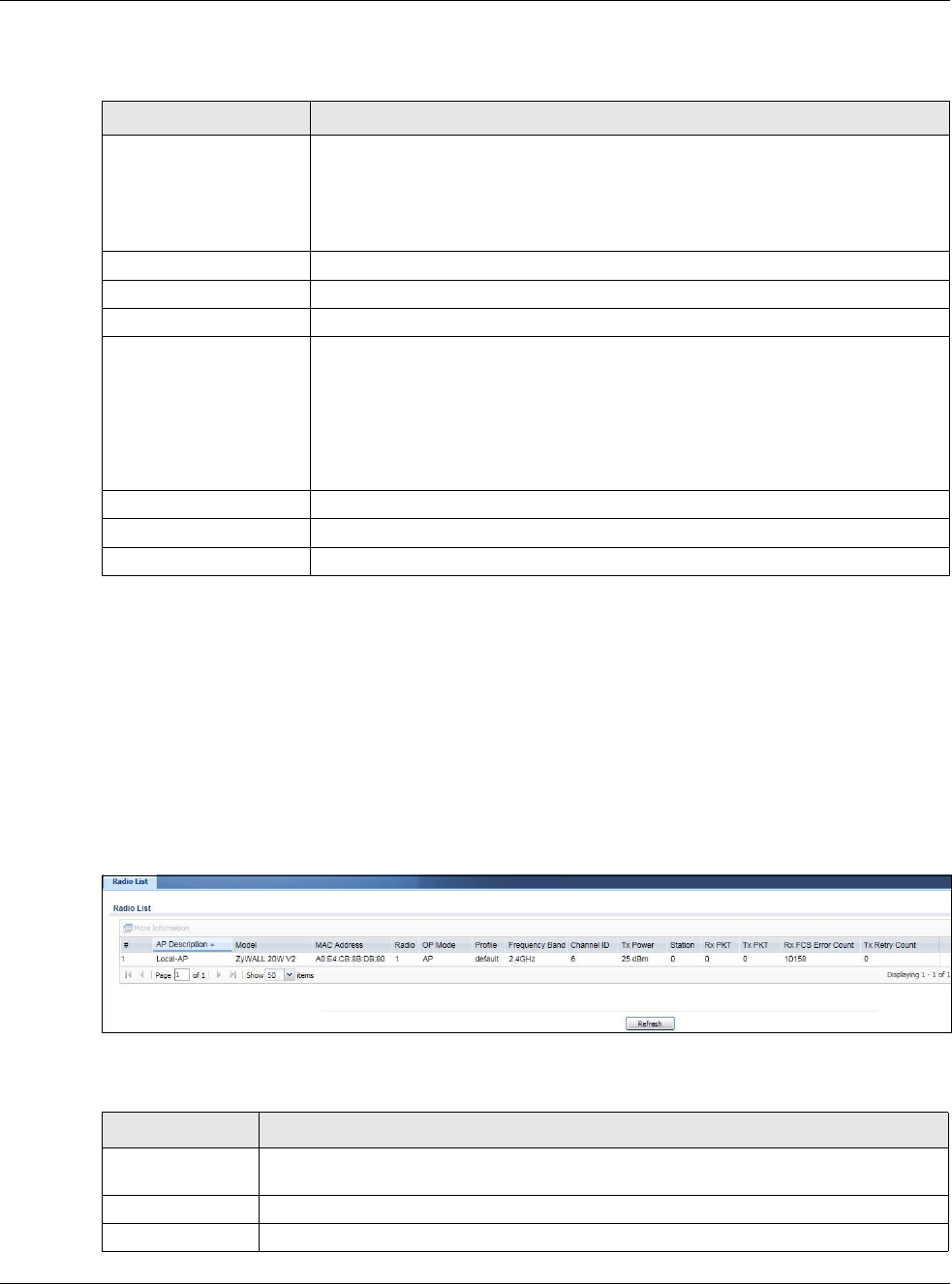
Chapter 6 Monitor
USG20(W)-VPN Series User’s Guide
117
The following table describes the fields in the previous screen.
6.14 Wireless
Wireless contains AP information and Station Info menus.
6.14.1 Wireless AP Information: Radio List
Click Monitor > Wireless > AP Information > Radio List to display the Radio List screen.
Figure 100 Monitor > Wireless > Radio List
The following table describes the labels in this screen.
Table 45 Monitor > System Status > Ethernet Neighbor
LABEL DESCRIPTION
Local Port (Description) This field displays the port of the USG, on which the neighboring device is
discovered.
For USGs that support Port Role, if ports 3 to 5 are grouped together and there is
a connection to P5 only, the USG will display P3 as the interface port number
(even though there is no connection to that port).
Model Name This field displays the model name of the discovered device.
System Name This field displays the system name of the discovered device.
Firmware Version This field displays the firmware version of the discovered device.
Port (Description) This field displays the first internal port on the discovered device. Internal is an
interface type displayed in the Network > Interface > Ethernet > Edit screen.
For example, if P1 and P2 are WAN, P3 to P5 are LAN, and P6 is DMZ, then USG
will display P3 as the first internal interface port number.
For USGs that support Port Role, if ports 3 to 5 are grouped together and there is
a connection to P5 only, the USG will display P3 as the first internal interface port
number (even though there is no connection to that port).
IP Address This field displays the IP address of the discovered device.
MAC Address This field displays the MAC address of the discovered device.
Refresh Click this button to update the information in the screen.
Table 46 Monitor > Wireless > Radio List
LABEL DESCRIPTION
More Information Click this icon to see the traffic statistics, station count, SSID, Security Mode and VLAN
ID information on the AP.
# This field is a sequential value, and it is not associated with a specific radio.
AP Description This field displays the description of the AP.

Chapter 6 Monitor
USG20(W)-VPN Series User’s Guide
118
Model This field displays the AP’s hardware model information. It displays N/A (not applicable)
only when the AP disconnects from the USG and the information is unavailable as a
result.
MAC Address This field displays the MAC address of the AP.
Radio This field displays the Radio number. For example 1.
OP Mode This field displays the operating mode of the AP. It displays n/a for the profile for a radio
not using an AP profile.
AP Mode means the AP can receive connections from wireless clients and pass their data
traffic through to the USG to be managed (or subsequently passed on to an upstream
gateway for managing).
MON Mode means the AP monitors the broadcast area for other APs, then passes their
information on to the USG. If an AP is set to this mode it cannot receive connections from
wireless clients.
Profile This field displays the AP Profile for the Radio. It displays n/A for the radio profile not
using an AP profile. It displays default if using a default profile.
Frequency Band This field displays the WLAN frequency band using the IEEE 802.11 a/b/g/n/ac standard
of 2.4 or 5 GHz.
Channel ID This field displays the WLAN channels using the IEEE 802.11 protocols.
Tx Power This field displays the transmission power the USG is using.
Station This field displays the station count information.
Rx PKT This field displays the data packets of incoming traffic on the AP.
Tx PKT This field displays the data packet of outgoing traffic on the AP.
Rx FCS Error
Count
This field displays the erroneous data packet count received and detected by Frame
Check Sequence (FCS)
Tx Retry Count This field displays the data packet count that were transmitted for retry.
Table 46 Monitor > Wireless > Radio List
LABEL DESCRIPTION
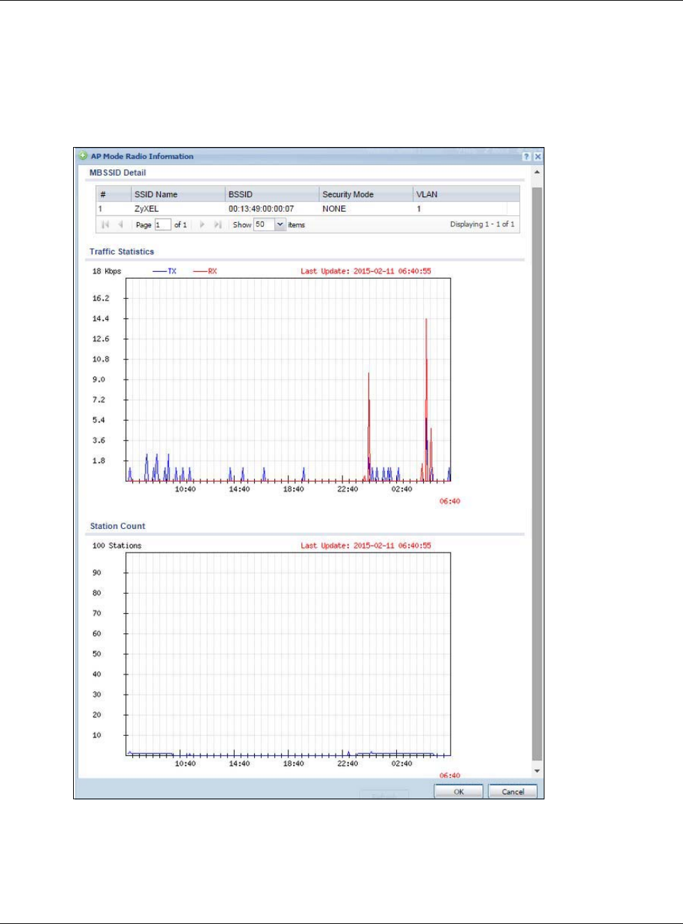
Chapter 6 Monitor
USG20(W)-VPN Series User’s Guide
119
6.14.2 Radio List More Information
This screen allows you to view detailed information about a selected radio’s SSID(s), wireless traffic
and wireless clients for the preceding 24 hours. To access this window, select an entry and click the
More Information button in the Radio List screen.
Figure 101 Monitor > Wireless > AP Information > Radio List > More Information
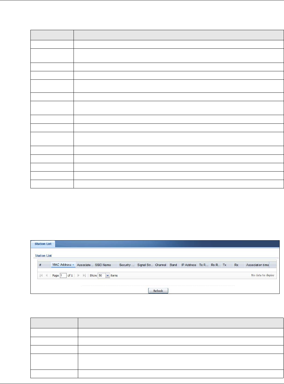
Chapter 6 Monitor
USG20(W)-VPN Series User’s Guide
120
The following table describes the labels in this screen.
6.14.3 Wireless Station Info
This screen displays information about connected wireless stations. Click Monitor > Wireless >
Station Information to display this screen.
Figure 102 Monitor > Wireless > Station List
The following table describes the labels in this screen.
Table 47 Monitor > Wireless > AP Info > Radio List > More Information
LABEL DESCRIPTION
MBSSID Detail This list shows information about the SSID(s) that is associated with the radio.
# This is the items sequential number in the list. It has no bearing on the actual data in this
list.
SSID Name This displays an SSID associated with this radio. There can be up to eight maximum.
BSSID This displays the MAC address associated with the SSID.
Security
Mode This displays the security mode in which the SSID is operating.
VLAN This displays the VLAN ID associated with the SSID.
Traffic Statistics This graph displays the overall traffic information about the radio over the preceding 24
hours.
y-axis This axis represents the amount of data moved across this radio per second.
x-axis This axis represents the amount of time over which the data moved across this radio.
Station Count This graph displays information about all the wireless clients that have connected to the
radio over the preceding 24 hours.
y-axis The y-axis represents the number of connected wireless clients.
x-axis The x-axis shows the time over which a wireless client was connected.
Last Update This field displays the date and time the information in the window was last updated.
OK Click this to close this window.
Cancel Click this to close this window.
Table 48 Monitor > Wireless > Station List
LABEL DESCRIPTION
# This field is a sequential value, and it is not associated with a specific station.
MAC Address This field displays the MAC address of the station.
Associated AP This field displays the AP that is associated with the station.
SSID Name This indicates the name of the wireless network to which the station is connected. A
single AP can have multiple SSIDs or networks.
Security Mode This field displays the security mode the station is using.
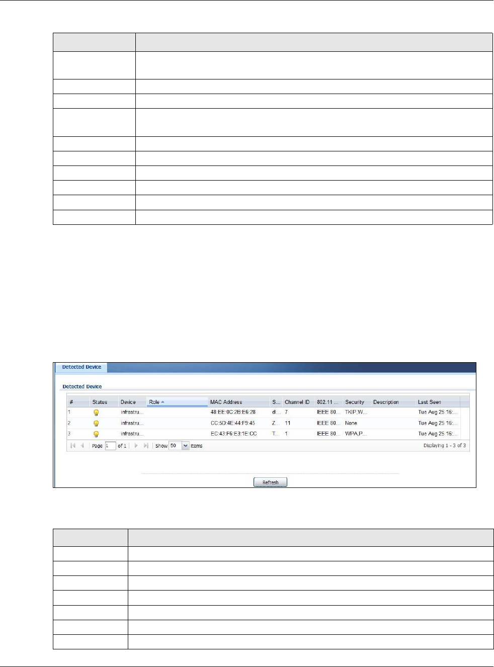
Chapter 6 Monitor
USG20(W)-VPN Series User’s Guide
121
6.14.4 Detected Device
Use this screen to view information about wireless devices detected by the AP. Click Monitor >
Wireless > Detected Device to access this screen.
Note: At least one radio of the APs connected to the USG must be set to monitor mode (in
the Configuration > Wireless > AP Management screen) in order to detect
other wireless devices in its vicinity.
Figure 103 Monitor > Wireless > Detected Device
The following table describes the labels in this screen.
Signal Strength This field displays the signal strength of the station. The signal strength mainly depends
on the antenna output power and the distance between the station and the AP.
Channel This indicates the number the channel used by the station to connect to the network.
Band This indicates the frequency band which is currently being used by the station.
IP Address This field displays the IP address of the station. An 169.x.x.x IP address is a private IP
address that means the station didn't get the IP address from a DHCP server.
Tx Rate This field displays the transmit data rate of the station.
Rx Rate This field displays the receive data rate of the station.
Tx This field displays the number of packets transmitted from the station.
Rx This field displays the number of packets received by the station.
Association Time This field displays the time duration the station was online and offline.
Refresh Click this to refresh the items displayed on this page.
Table 48 Monitor > Wireless > Station List
LABEL DESCRIPTION
Table 49 Monitor > Wireless > Detected Device
LABEL DESCRIPTION
# This is the station’s index number in this list.
Status This indicates the detected device’s status.
Device This indicates the detected device’s network type (such as infrastructure or ad-hoc).
MAC Address This indicates the detected device’s MAC address.
SSID Name This indicates the detected device’s SSID.
Channel ID This indicates the detected device’s channel ID.
802.11 Mode This indicates the 802.11 mode (a/b/g/n/ac) transmitted by the detected device.
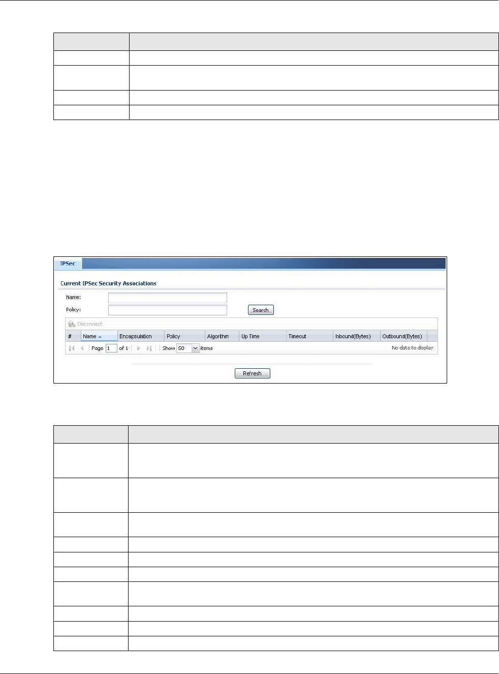
Chapter 6 Monitor
USG20(W)-VPN Series User’s Guide
122
6.15 The IPSec Monitor Screen
You can use the IPSec Monitor screen to display and to manage active IPSec To access this
screen, click Monitor > VPN Monitor > IPSec. The following screen appears. SAs. Click a
column’s heading cell to sort the table entries by that column’s criteria. Click the heading cell again
to reverse the sort order.
Figure 104 Monitor > VPN Monitor > IPSec
Each field is described in the following table.
Security This indicates the encryption method (if any) used by the detected device.
Description This displays the detected device’s description. For more on managing friendly and rogue
APs, see the Configuration > Wireless > MON Mode screen.
Last Seen This indicates the last time the device was detected by the USG.
Refresh Click this to refresh the items displayed on this page.
Table 49 Monitor > Wireless > Detected Device (continued)
LABEL DESCRIPTION
Table 50 Monitor > VPN Monitor > IPSec
LABEL DESCRIPTION
Name Type the name of a IPSec SA here and click Search to find it (if it is associated). You can
use a keyword or regular expression. Use up to 30 alphanumeric and _+-
.()!$*^:?|{}[]<>/ characters. See Section 6.15.1 on page 123 for more details.
Policy Type the IP address(es) or names of the local and remote policies for an IPSec SA and click
Search to find it. You can use a keyword or regular expression. Use up to 30 alphanumeric
and _+-.()!$*^:?|{}[]<>/ characters. See Section 6.15.1 on page 123 for more details.
Search Click this button to search for an IPSec SA that matches the information you specified
above.
Disconnect Select an IPSec SA and click this button to disconnect it.
# This field is a sequential value, and it is not associated with a specific SA.
Name This field displays the name of the IPSec SA.
Policy This field displays the content of the local and remote policies for this IPSec SA. The IP
addresses, not the address objects, are displayed.
IKE Name This field displays the Internet Key Exchange (IKE) name.
Cookies This field displays the cookies information that initiates the IKE.
My Address This field displays the IP address of local computer.
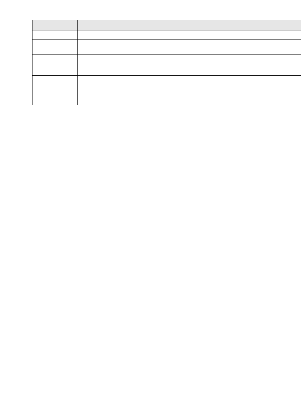
Chapter 6 Monitor
USG20(W)-VPN Series User’s Guide
123
6.15.1 Regular Expressions in Searching IPSec SAs
A question mark (?) lets a single character in the VPN connection or policy name vary. For example,
use “a?c” (without the quotation marks) to specify abc, acc and so on.
Wildcards (*) let multiple VPN connection or policy names match the pattern. For example, use
“*abc” (without the quotation marks) to specify any VPN connection or policy name that ends with
“abc”. A VPN connection named “testabc” would match. There could be any number (of any type) of
characters in front of the “abc” at the end and the VPN connection or policy name would still match.
A VPN connection or policy name named “testacc” for example would not match.
A * in the middle of a VPN connection or policy name has the USG check the beginning and end and
ignore the middle. For example, with “abc*123”, any VPN connection or policy name starting with
“abc” and ending in “123” matches, no matter how many characters are in between.
The whole VPN connection or policy name has to match if you do not use a question mark or
asterisk.
6.16 The SSL Screen
The USG keeps track of the users who are currently logged into the VPN SSL client. Click Monitor
> VPN Monitor > SSL to display the user list.
Use this screen to do the following:
• View a list of active SSL VPN connections.
• Log out individual users and delete related session information.
Once a user logs out, the corresponding entry is removed from the screen.
Secure Gateway This field displays the secure gateway information.
Up Time This field displays how many seconds the IPSec SA has been active. This field displays N/A
if the IPSec SA uses manual keys.
Timeout This field displays how many seconds remain in the SA life time, before the USG
automatically disconnects the IPSec SA. This field displays N/A if the IPSec SA uses
manual keys.
Inbound (Bytes) This field displays the amount of traffic that has gone through the IPSec SA from the
remote IPSec router to the USG since the IPSec SA was established.
Outbound
(Bytes)
This field displays the amount of traffic that has gone through the IPSec SA from the USG
to the remote IPSec router since the IPSec SA was established.
Table 50 Monitor > VPN Monitor > IPSec (continued)
LABEL DESCRIPTION
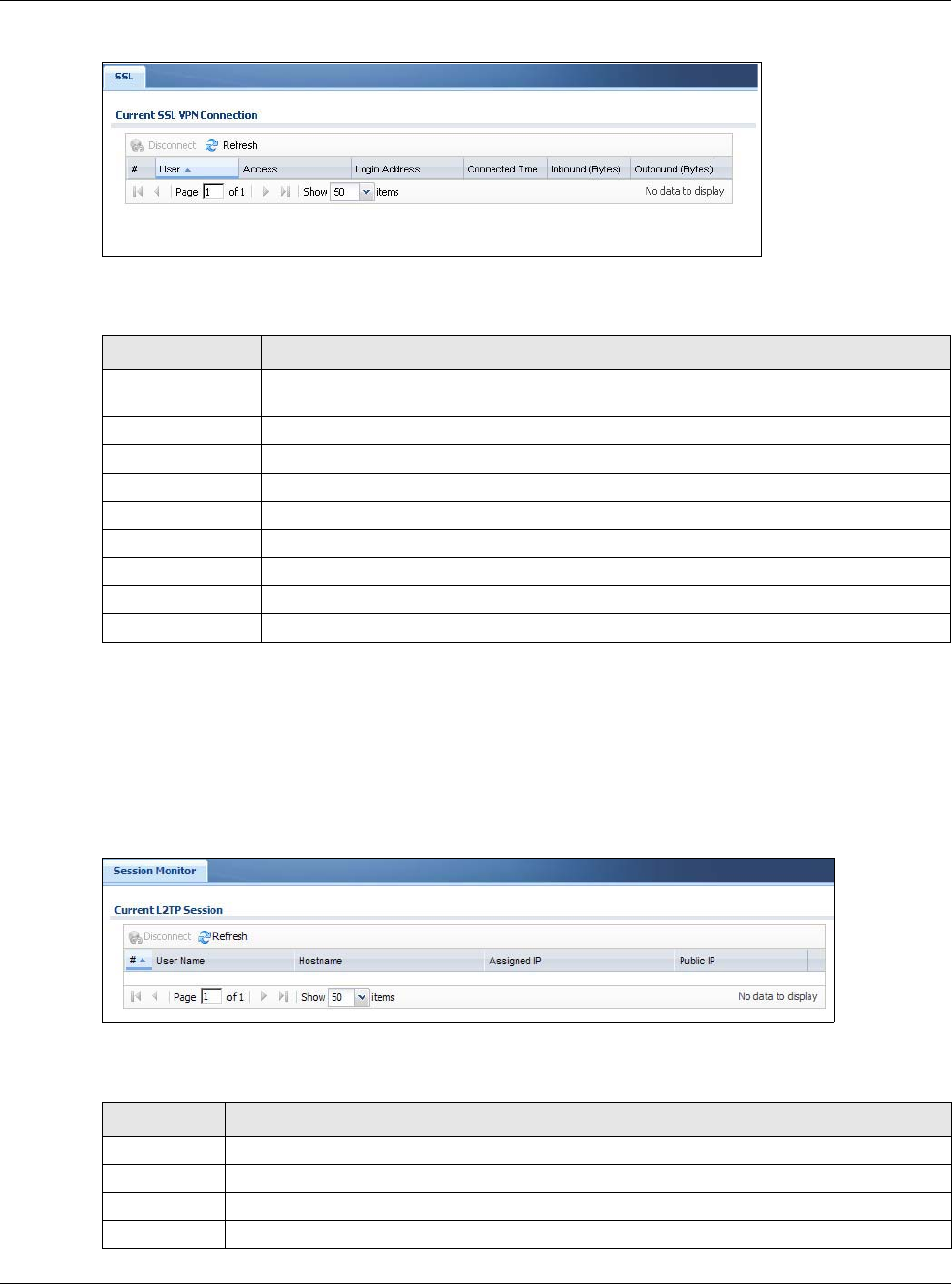
Chapter 6 Monitor
USG20(W)-VPN Series User’s Guide
124
Figure 105 Monitor > VPN Monitor > SSL
The following table describes the labels in this screen.
6.17 The L2TP over IPSec Session Monitor Screen
Click Monitor > VPN Monitor > L2TP over IPSec to open the following screen. Use this screen
to display and manage the USG’s connected L2TP VPN sessions.
Figure 106 Monitor > VPN Monitor > L2TP over IPSec
The following table describes the fields in this screen.
Table 51 Monitor > VPN Monitor > SSL
LABEL DESCRIPTION
Disconnect Select a connection and click this button to terminate the user’s connection and delete
corresponding session information from the USG.
Refresh Click Refresh to update this screen.
# This field is a sequential value, and it is not associated with a specific SSL.
User This field displays the account user name used to establish this SSL VPN connection.
Access This field displays the name of the SSL VPN application the user is accessing.
Login Address This field displays the IP address the user used to establish this SSL VPN connection.
Connected Time This field displays the time this connection was established.
Inbound (Bytes) This field displays the number of bytes received by the USG on this connection.
Outbound (Bytes) This field displays the number of bytes transmitted by the USG on this connection.
Table 52 Monitor > VPN Monitor > L2TP over IPSec
LABEL DESCRIPTION
Disconnect Select a connection and click this button to disconnect it.
Refresh Click Refresh to update this screen.
# This field is a sequential value, and it is not associated with a specific L2TP VPN session.
User Name This field displays the remote user’s user name.
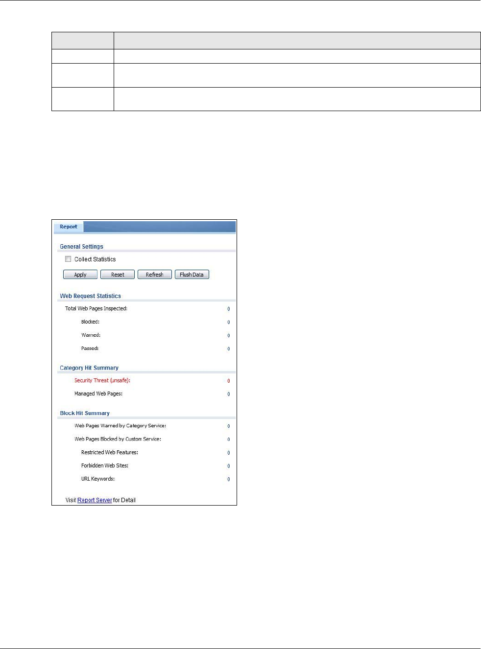
Chapter 6 Monitor
USG20(W)-VPN Series User’s Guide
125
6.18 The Content Filter Screen
Click Monitor > UTM Statistics > Content Filter to display the following screen. This screen
displays content filter statistics.
Figure 107 Monitor > UTM Statistics > Content Filter
Hostname This field displays the name of the computer that has this L2TP VPN connection with the USG.
Assigned IP This field displays the IP address that the USG assigned for the remote user’s computer to use
within the L2TP VPN tunnel.
Public IP This field displays the public IP address that the remote user is using to connect to the
Internet.
Table 52 Monitor > VPN Monitor > L2TP over IPSec (continued)
LABEL DESCRIPTION

Chapter 6 Monitor
USG20(W)-VPN Series User’s Guide
126
The following table describes the labels in this screen.
Table 53 Monitor > UTM Statistics > Content Filter
LABEL DESCRIPTION
General Settings
Collect Statistics Select this check box to have the USG collect content filtering statistics.
The collection starting time displays after you click Apply. All of the statistics in this
screen are for the time period starting at the time displayed here. The format is
year, month, day and hour, minute, second. All of the statistics are erased if you
restart the USG or click Flush Data. Collecting starts over and a new collection
start time displays.
Apply Click Apply to save your changes back to the USG.
Reset Click Reset to return the screen to its last-saved settings.
Refresh Click this button to update the report display.
Flush Data Click this button to discard all of the screen’s statistics and update the report
display.
Web Request Statistics
Total Web Pages
Inspected
This field displays the number of web pages that the USG’s content filter feature has
checked.
Blocked This is the number of web pages that the USG blocked access.
Warned This is the number of web pages for which the USG displayed a warning message to
the access requesters.
Passed This is the number of web pages to which the USG allowed access.
Category Hit Summary
Security Threat
(unsafe)
This is the number of requested web pages that the USG’s content filtering service
identified as posing a threat to users.
Managed Web Pages This is the number of requested web pages that the USG’s content filtering service
identified as belonging to a category that was selected to be managed.
Block Hit Summary
Web Pages Warned by
Category Service
This is the number of web pages that matched an external database content
filtering category selected in the USG and for which the USG displayed a warning
before allowing users access.
Web Pages Blocked by
Custom Service
This is the number of web pages to which the USG did not allow access due to the
content filtering custom service configuration.
Restricted Web
Features This is the number of web pages to which the USG limited access or removed
cookies due to the content filtering custom service's restricted web features
configuration.
Forbidden Web Sites This is the number of web pages to which the USG did not allow access because
they matched the content filtering custom service’s forbidden web sites list.
URL Keywords This is the number of web pages to which the USG did not allow access because
they contained one of the content filtering custom service’s list of forbidden
keywords.
Web Pages Blocked
Without Policy
This is the number of web pages to which the USG did not allow access because
they were not rated by the external database content filtering service.
Report Server Click this link to go to http://www.myZyXEL.com where you can view content
filtering reports after you have activated the category-based content filtering
subscription service.
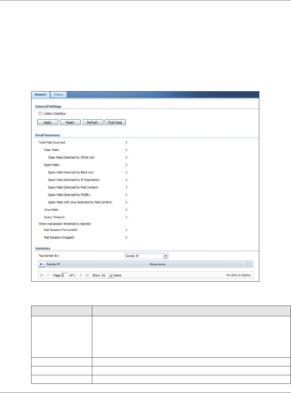
Chapter 6 Monitor
USG20(W)-VPN Series User’s Guide
127
6.19 The Anti-Spam Screens
The Anti-Spam menu contains the Report and Status screens.
6.19.1 Anti-Spam Report
Click Monitor > UTM Statistics > Anti-Spam to display the following screen. This screen displays
spam statistics.
Figure 108 Monitor > UTM Statistics > Anti-Spam
The following table describes the labels in this screen.
Table 54 Monitor > UTM Statistics > Anti-Spam
LABEL DESCRIPTION
Collect Statistics Select this check box to have the USG collect anti-spam statistics.
The collection starting time displays after you click Apply. All of the statistics in this
screen are for the time period starting at the time displayed here. The format is
year, month, day and hour, minute, second. All of the statistics are erased if you
restart the USG or click Flush Data. Collecting starts over and a new collection
start time displays.
Apply Click Apply to save your changes back to the USG.
Reset Click Reset to return the screen to its last-saved settings.
Refresh Click this button to update the report display.

Chapter 6 Monitor
USG20(W)-VPN Series User’s Guide
128
Flush Data Click this button to discard all of the screen’s statistics and update the report
display.
Total Mails Scanned This field displays the number of e-mails that the USG’s anti-spam feature has
checked.
Clear Mails This is the number of e-mails that the USG has determined to not be spam.
Clear Mails Detected by
Whitelist
This is the number of e-mails that matched an entry in the USG’s anti-spam white
list.
Spam Mails This is the number of e-mails that the USG has determined to be spam.
Spam Mails Detected by
Black List
This is the number of e-mails that matched an entry in the USG’s anti-spam black
list.
Spam Mails Detected by
IP Reputation
This is the number of e-mails that the USG has determined to be spam by IP
Reputation. Spam or Unwanted Bulk Email is determined by the sender’s IP
address.
Spam Mails Detected by
Mail Content
This is the number of e-mails that the USG has determined to have malicious
contents.
Spam Mails Detected by
DNSBL
The USG can check the sender and relay IP addresses in an e-mail’s header against
DNS (Domain Name Service)-based spam Black Lists (DNSBLs). This is the number
of e-mails that had a sender or relay IP address in the header which matched one of
the DNSBLs that the USG uses.
Spam Mails with Virus
Detected by Mail
Content
This is the number of e-mails that the USG has determined to have malicious
contents and attached with virus.
Virus Mails This is the number of e-mails that the USG has determined to be attached with
virus.
Query Timeout This is how many queries that were sent to the USG’s configured list of DNSBL
domains or Mail Scan services and did not receive a response in time.
Mail Sessions
Forwarded
This is how many e-mail sessions the USG allowed because they exceeded the
maximum number of e-mail sessions that the anti-spam feature can check at a
time.
You can see the USG’s threshold of concurrent e-mail sessions in the Anti-Spam >
Status screen.
Use the Anti-Spam > General screen to set whether the USG forwards or drops
sessions that exceed this threshold.
Mail Sessions Dropped This is how many e-mail sessions the USG dropped because they exceeded the
maximum number of e-mail sessions that the anti-spam feature can check at a
time.
You can see the USG’s threshold of concurrent e-mail sessions in the Anti-Spam >
Status screen.
Use the Anti-Spam > General screen to set whether the USG forwards or drops
sessions that exceed this threshold.
Top Sender By Use this field to list the top e-mail or IP addresses from which the USG has detected
the most spam.
Select Sender IP to list the source IP addresses from which the USG has detected
the most spam.
Select Sender Email Address to list the top e-mail addresses from which the USG
has detected the most spam.
#This field displays the entry’s rank in the list of the top entries.
Sender IP This column displays when you display the entries by Sender IP. It shows the
source IP address of spam e-mails that the USG has detected.
Table 54 Monitor > UTM Statistics > Anti-Spam (continued)
LABEL DESCRIPTION
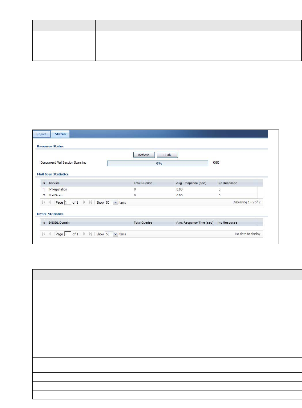
Chapter 6 Monitor
USG20(W)-VPN Series User’s Guide
129
6.19.2 The Anti-Spam Status Screen
Click Monitor > UTM Statistics > Anti-Spam > Status to display the Anti-Spam Status screen.
Use the Anti-Spam Status screen to see how many e-mail sessions the anti-spam feature is
scanning and statistics for the DNSBLs.
Figure 109 Monitor > UTM Statistics > Anti-Spam > Status
The following table describes the labels in this screen.
Sender Email Address This column displays when you display the entries by Sender Email Address. This
column displays the e-mail addresses from which the USG has detected the most
spam.
Occurrence This field displays how many spam e-mails the USG detected from the sender.
Table 54 Monitor > UTM Statistics > Anti-Spam (continued)
LABEL DESCRIPTION
Table 55 Monitor > UTM Statistics > Anti-Spam > Status
LABEL DESCRIPTION
Refresh Click this button to update the information displayed on this screen.
Flush Click this button to clear the DNSBL statistics. This also clears the concurrent mail
session scanning bar’s historical high.
Concurrent Mail Session
Scanning
The darker shaded part of the bar shows how much of the USG’s total spam
checking capability is currently being used.
The lighter shaded part of the bar and the pop-up show the historical high.
The first number to the right of the bar is how many e-mail sessions the USG is
presently checking for spam. The second number is the maximum number of e-
mail sessions that the USG can check at once. An e-mail session is when an e-
mail client and e-mail server (or two e-mail servers) connect through the USG.
Mail Scan Statistics These are the statistics for the service the USG uses. These statistics are for when
the USG actually queries the service servers.
#This is the entry’s index number in the list.
Service This displays the name of the service.
Total Queries This is the total number of queries the USG has sent to this service.
Chapter 6 Monitor
USG20(W)-VPN Series User’s Guide
130
6.20 Log Screens
Log messages are stored in two separate logs, one for regular log messages and one for debugging
messages. In the regular log, you can look at all the log messages by selecting All Logs, or you can
select a specific category of log messages (for example, security policy or user). You can also look
at the debugging log by selecting Debug Log. All debugging messages have the same priority.
6.20.1 View Log
To access this screen, click Monitor > Log. The log is displayed in the following screen.
Note: When a log reaches the maximum number of log messages, new log messages
automatically overwrite existing log messages, starting with the oldest existing log
message first.
• The maximum possible number of log messages in the USG varies by model.
Events that generate an alert (as well as a log message) display in red. Regular logs display in
black. Click a column’s heading cell to sort the table entries by that column’s criteria. Click the
heading cell again to reverse the sort order. The Web Configurator saves the filter settings if you
leave the View Log screen and return to it later.
Avg. Response Time (sec) This is the average for how long it takes to receive a reply from this service.
No Response This is how many queries the USG sent to this service without receiving a reply.
DNSBL Statistics These are the statistics for the DNSBL the USG uses. These statistics are for when
the USG actually queries the DNSBL servers. Matches for DNSBL responses stored
in the cache do not affect these statistics.
#This is the entry’s index number in the list.
DNSBL Domain These are the DNSBLs the USG uses to check sender and relay IP addresses in e-
mails.
Total Queries This is the total number of DNS queries the USG has sent to this DNSBL.
Avg. Response Time (sec) This is the average for how long it takes to receive a reply from this DNSBL.
No Response This is how many DNS queries the USG sent to this DNSBL without receiving a
reply.
Table 55 Monitor > UTM Statistics > Anti-Spam > Status (continued)
LABEL DESCRIPTION
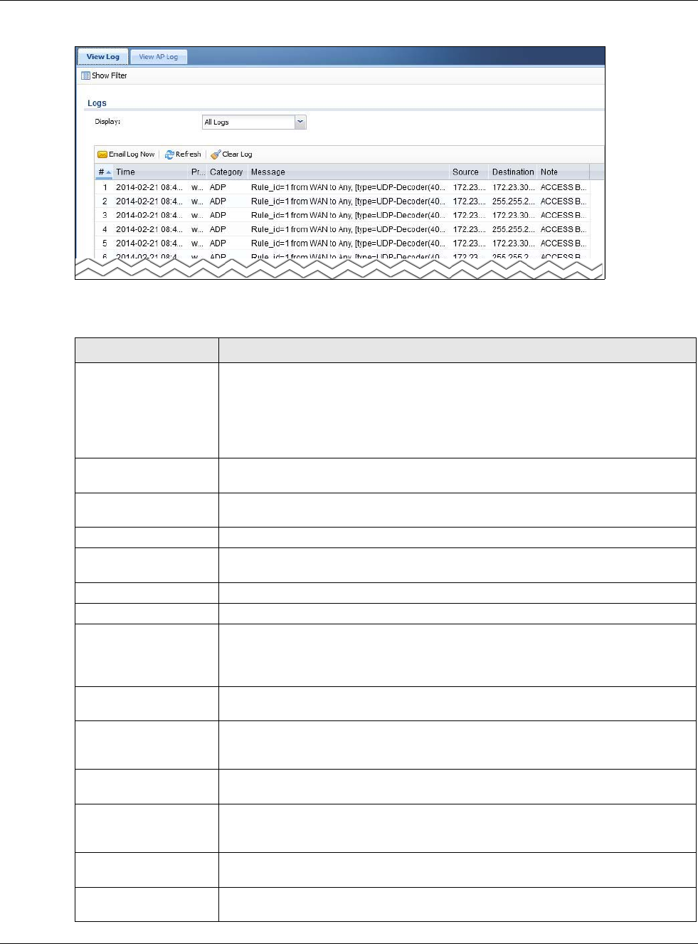
Chapter 6 Monitor
USG20(W)-VPN Series User’s Guide
131
Figure 110 Monitor > Log > View Log
The following table describes the labels in this screen.
Table 56 Monitor > Log > View Log
LABEL DESCRIPTION
Show Filter Click this button to show or hide the filter settings.
If the filter settings are hidden, the Display, Email Log Now, Refresh, and Clear
Log fields are available.
If the filter settings are shown, the Display, Priority, Source Address,
Destination Address, Service, Keyword, and Search fields are available.
Display Select the category of log message(s) you want to view. You can also view All Logs
at one time, or you can view the Debug Log.
Email Log Now Click this button to send log message(s) to the Active e-mail address(es) specified
in the Send Log To field on the Log Settings page.
Refresh Click this button to update the information in the screen.
Clear Log Click this button to clear the whole log, regardless of what is currently displayed on
the screen.
# This field is a sequential value, and it is not associated with a specific log message.
Time This field displays the time the log message was recorded.
Priority This displays when you show the filter. Select the priority of log messages to
display. The log displays the log messages with this priority or higher. Choices are:
any, emerg, alert, crit, error, warn, notice, and info, from highest priority to
lowest priority. This field is read-only if the Category is Debug Log.
Category This field displays the log that generated the log message. It is the same value used
in the Display and (other) Category fields.
Message This field displays the reason the log message was generated. The text “[count=x]”,
where x is a number, appears at the end of the Message field if log consolidation is
turned on and multiple entries were aggregated to generate into this one.
Source This displays when you show the filter. Type the source IP address of the incoming
packet that generated the log message. Do not include the port in this filter.
Destination This displays when you show the filter. Type the IP address of the destination of the
incoming packet when the log message was generated. Do not include the port in
this filter.
Protocol This displays when you show the filter. Select a service protocol whose log
messages you would like to see.
Search This displays when you show the filter. Click this button to update the log using the
current filter settings.
Chapter 6 Monitor
USG20(W)-VPN Series User’s Guide
132
Priority This field displays the priority of the log message. It has the same range of values
as the Priority field above.
Source This field displays the source IP address and the port number in the event that
generated the log message.
Destination This field displays the destination IP address and the port number of the event that
generated the log message.
Note This field displays any additional information about the log message.
Table 56 Monitor > Log > View Log (continued)
LABEL DESCRIPTION

USG20(W)-VPN Series User’s Guide
133
CHAPTER 7
Licensing
7.1 Registration Overview
Use the Configuration > Licensing > Registration screens to register your USG and manage its
service subscriptions.
•Use the Registration screen (see Section 7.1.2 on page 134) to go to portal.myzyxel.com to register your
USG and activate a service, such as content filtering.
•Use the Service screen (see Section 7.1.3 on page 134) to display the status of your service registrations
and upgrade licenses.
Note: The USG models need a license for UTM (Unified Threat management) functionality.
7.1.1 What you Need to Know
This section introduces the topics covered in this chapter.
myZyXEL.com
myZyXEL.com is ZyXEL’s online services center where you can register your USG and manage
subscription services available for the USG. To update signature files or use a subscription service,
you have to register the USG and activate the corresponding service at myZyXEL.com (through the
USG).
Note: You need to create a myZyXEL.com account before you can register your device
and activate the services at myZyXEL.com.
You need your USG’s serial number and LAN MAC address to register it. Refer to the web site’s on-
line help for details.
Subscription Services Available
The USG can use anti-spam, SSL VPN, and content filtering subscription services.
The USG models need a license for UTM (Unified Threat Management) functionality - see Section
1.1 on page 18 for details.
You can purchase an iCard and enter the license key from it, at www.myzyxel.com to have the USG
use UTM services or have the USG use more SSL VPN tunnels. See below the respective chapters in
this guide for more information about UTM features.
Chapter 7 Licensing
USG20(W)-VPN Series User’s Guide
134
7.1.2 Registration Screen
Click the link in this screen to register your USG at myZyXEL.com. The USG should already have
Internet access before you can access it. Click Configuration > Licensing > Registration in the
navigation panel to open the screen as shown next.
Click on the icon to go to the OneSecurity.com website where there is guidance on configuration
walkthrough and other information.
Figure 111 Configuration > Licensing > Registration > portal.myzyxel.com
7.1.3 Service Screen
Use this screen to display the status of your service registrations and upgrade licenses. To activate
or extend a standard service subscription, purchase an iCard and enter the iCard’s PIN number
(license key) in this screen. Click Configuration > Licensing > Registration > Service to open
the screen as shown next.
Figure 112 Configuration > Licensing > Registration > Service
The following table describes the labels in this screen.
Table 57 Configuration > Licensing > Registration > Service
LABEL DESCRIPTION
License Status
# This is the entry’s position in the list.
Service This lists the services that available on the USG.
Status This field displays whether a service is activated (Licensed) or not (Not
Licensed) or expired (Expired).
Registration Type This field displays whether you applied for a trial application (Trial) or
registered a service with your iCard’s PIN number (Standard). This field is
blank when a service is not activated.
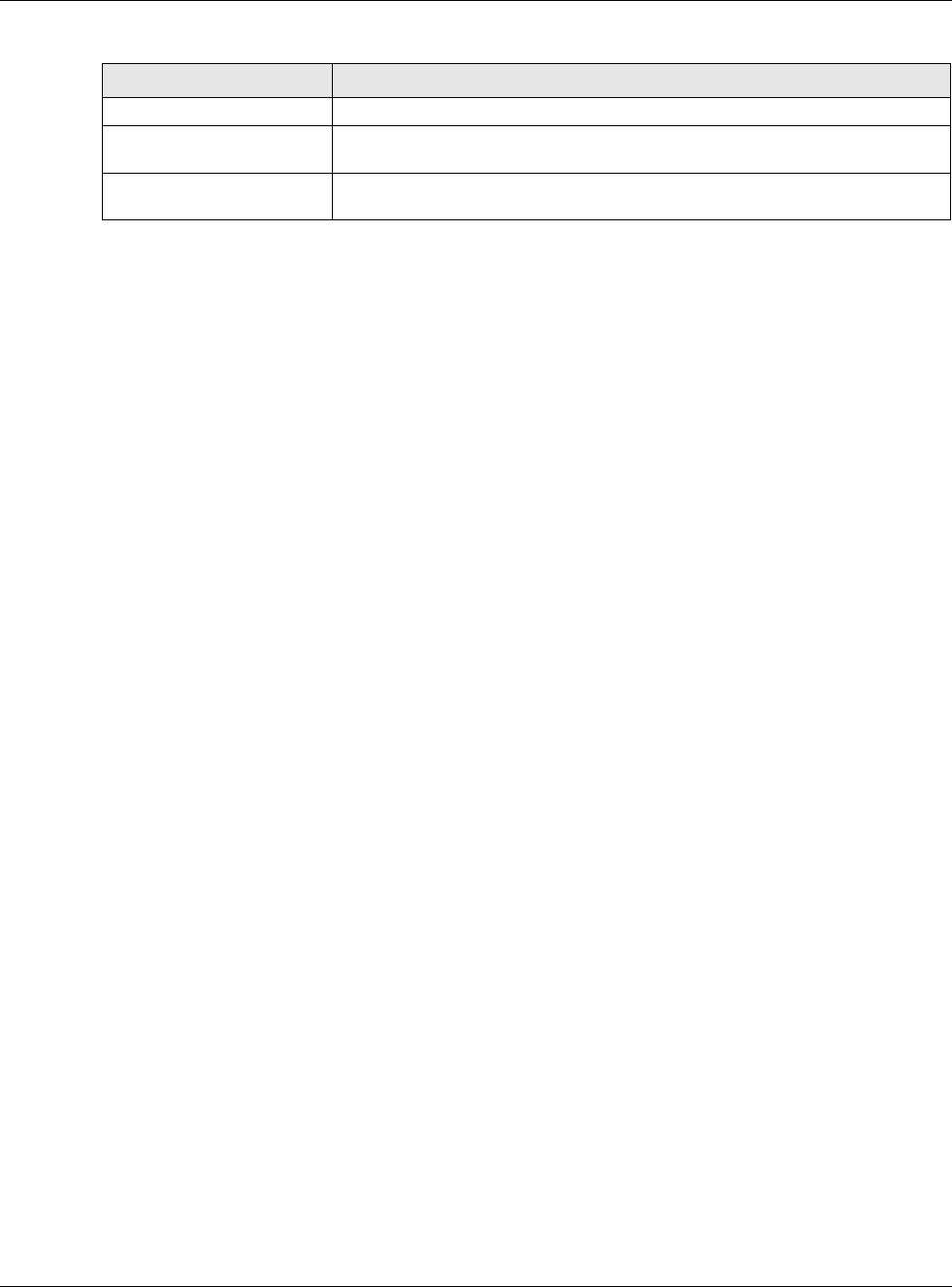
Chapter 7 Licensing
USG20(W)-VPN Series User’s Guide
135
Expiration Date This field displays the date your service expires.
Count This field displays how many VPN tunnels you can use with your current
license. This field does not apply to the other services.
Service License Refresh Click this button to renew service license information (such as the registration
status and expiration day).
Table 57 Configuration > Licensing > Registration > Service (continued)
LABEL DESCRIPTION

USG20(W)-VPN Series User’s Guide
136
CHAPTER 8
Wireless
8.1 Overview
Use the Wireless screens to configure how the USG manages the Access Points (APs) that are
connected to it.
8.1.1 What You Can Do in this Chapter
•The AP Management screen (Section 8.2 on page 137) manages all of the APs connected to the
USG.
•The DCS screen (Section 8.2 on page 137) configures dynamic radio channel selection.
8.1.2 What You Need to Know
The following terms and concepts may help as you read this chapter.
Station / Wireless Client
A station or wireless client is any wireless-capable device that can connect to an AP using a wireless
signal.
Dynamic Channel Selection (DCS)
Dynamic Channel Selection (DCS) is a feature that allows an AP to automatically select the radio
channel upon which it broadcasts by scanning the area around it and determining what channels
are currently being used by other devices.
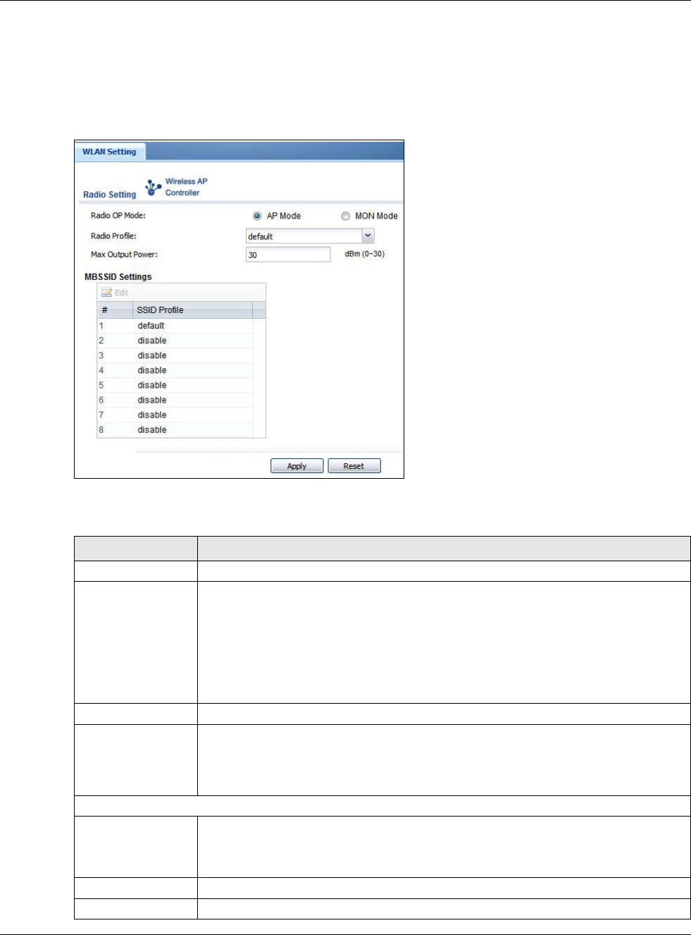
Chapter 8 Wireless
USG20(W)-VPN Series User’s Guide
137
8.2 AP Management Screen
Use this screen to manage the USG’s general wireless settings. Click Configuration > Wireless >
AP Management to access this screen.
Figure 113 Configuration > Wireless > AP Management
Each field is described in the following table.
Table 58 Configuration > Wireless > AP Management
LABEL DESCRIPTION
Radio Setting
Radio OP Mode Select the operating mode.
AP Mode means the radio can receive connections from wireless clients and pass their
data traffic through to the USG to be managed (or subsequently passed on to an
upstream gateway for managing).
MON Mode means the radio monitors the broadcast area for other APs, then passes
their information on to the USG where it can be determined if those APs are friendly or
rogue. If a radio is set to this mode it cannot receive connections from wireless clients.
Radio Profile Select the radio profile the radio uses.
Max Output Power Enter the output power (between 0 to 30 dBm) of the USG in this field. If there is a high
density of APs in an area, decrease the output power of the USG to reduce interference
with other APs.
Note: Reducing the output power also reduces the USG’s effective broadcast radius.
MBSSID Settings
Edit Double-click an entry or select it and click Edit to open a screen where you can modify
the entry’s settings. In some tables you can just click a table entry and edit it directly in
the table. For those types of tables small red triangles display for table entries with
changes that you have not yet applied.
# This field shows the index number of the SSID
SSID Profile This field displays the SSID profile that is associated with the radio profile.
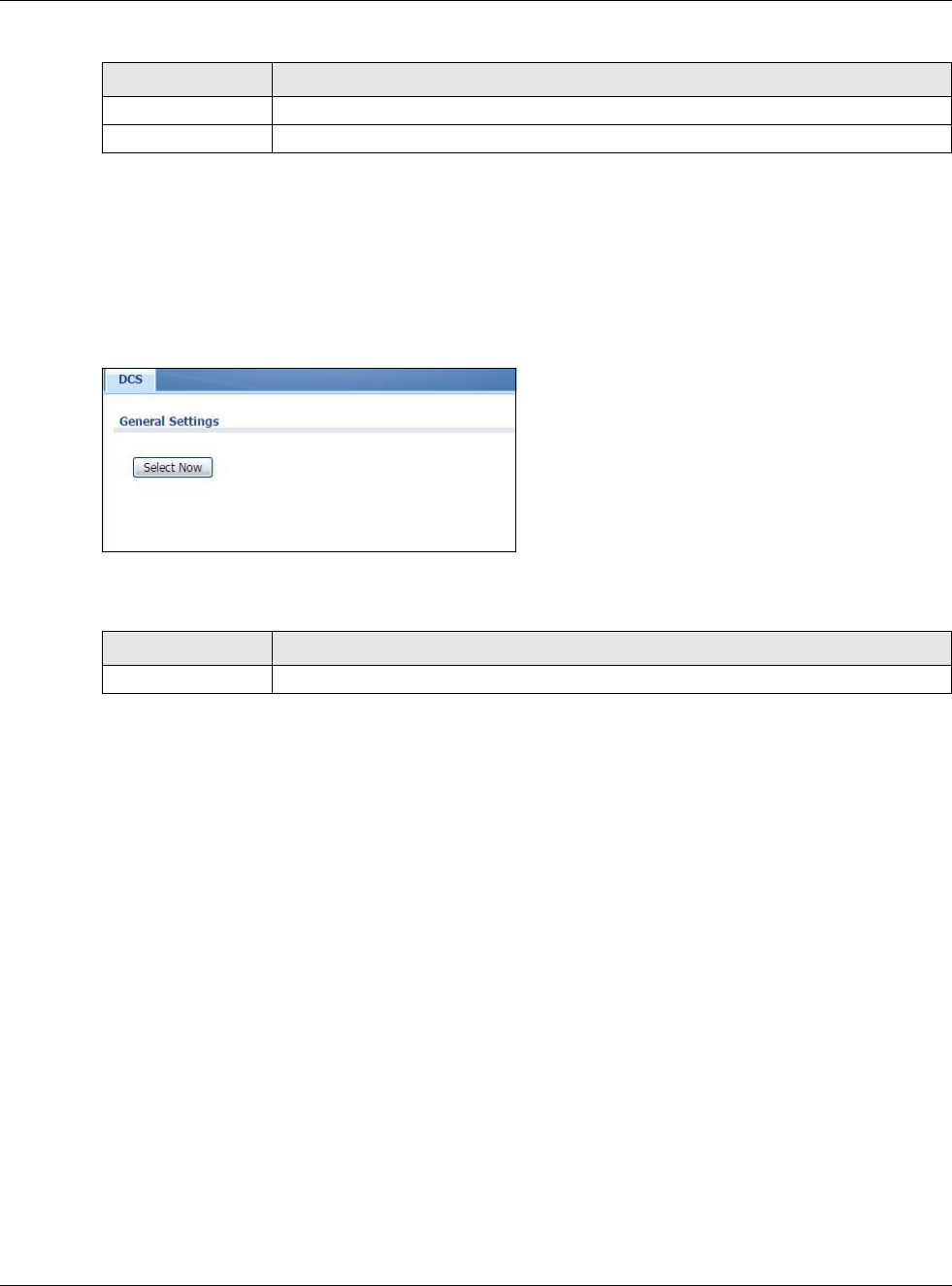
Chapter 8 Wireless
USG20(W)-VPN Series User’s Guide
138
8.3 DCS Screen
Use this screen to configure dynamic radio channel selection. Click Configuration > Wireless >
DCS to access this screen.
Figure 114 Configuration > Wireless > DCS
Each field is described in the following table.
8.4 Technical Reference
The following section contains additional technical information about the features described in this
chapter.
8.4.1 Dynamic Channel Selection
When numerous APs broadcast within a given area, they introduce the possibility of heightened
radio interference, especially if some or all of them are broadcasting on the same radio channel. If
the interference becomes too great, then the network administrator must open his AP configuration
options and manually change the channel to one that no other AP is using (or at least a channel
that has a lower level of interference) in order to give the connected stations a minimum degree of
interference. Dynamic channel selection frees the network administrator from this task by letting
the AP do it automatically. The AP can scan the area around it looking for the channel with the least
amount of interference.
In the 2.4 GHz spectrum, each channel from 1 to 13 is broken up into discrete 22 MHz segments
that are spaced 5 MHz apart. Channel 1 is centered on 2.412 GHz while channel 13 is centered on
2.472 GHz.
Apply Click Apply to save your changes back to the USG.
Reset Click Reset to close the window with changes unsaved.
Table 58 Configuration > Wireless > AP Management (continued)
LABEL DESCRIPTION
Table 59 Configuration > Wireless > DCS
LABEL DESCRIPTION
Select Now Click this to have the USG scan for and select an available channel immediately.
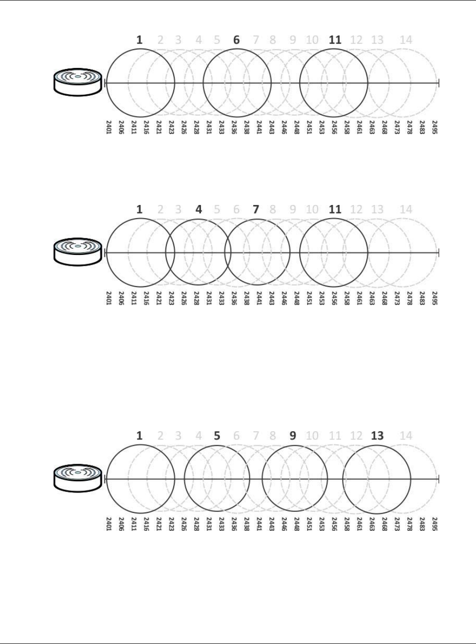
Chapter 8 Wireless
USG20(W)-VPN Series User’s Guide
139
Figure 115 An Example Three-Channel Deployment
Three channels are situated in such a way as to create almost no interference with one another if
used exclusively: 1, 6 and 11. When an AP broadcasts on any of these three channels, it should not
interfere with neighboring APs as long as they are also limited to same trio.
Figure 116 An Example Four-Channel Deployment
However, some regions require the use of other channels and often use a safety scheme with the
following four channels: 1, 4, 7 and 11. While they are situated sufficiently close to both each other
and the three so-called “safe” channels (1,6 and 11) that interference becomes inevitable, the
severity of it is dependent upon other factors: proximity to the affected AP, signal strength, activity,
and so on.
Finally, there is an alternative four channel scheme for ETSI, consisting of channels 1, 5, 9, 13. This
offers significantly less overlap that the other one.
Figure 117 An Alternative Four-Channel Deployment