ZyXEL Communications USG20W-VPN VPN Firewall User Manual Book
ZyXEL Communications Corporation VPN Firewall Book
Contents
- 1. Users Manual Part 1
- 2. Users Manual Part 2
- 3. Users Manual Part 3
- 4. Users Manual Part 4
- 5. Users Manual Part 5
Users Manual Part 5

USG20(W)-VPN Series User’s Guide
537
CHAPTER 30
System
30.1 Overview
Use the system screens to configure general USG settings.
30.1.1 What You Can Do in this Chapter
•Use the System > Host Name screen (see Section 30.2 on page 538) to configure a unique
name for the USG in your network.
•Use the System > USB Storage screen (see Section 30.3 on page 538) to configure the
settings for the connected USB devices.
•Use the System > Date/Time screen (see Section 30.4 on page 539) to configure the date and
time for the USG.
•Use the System > Console Speed screen (see Section 30.5 on page 543) to configure the
console port speed when you connect to the USG via the console port using a terminal emulation
program.
•Use the System > DNS screen (see Section 30.6 on page 544) to configure the DNS (Domain
Name System) server used for mapping a domain name to its corresponding IP address and vice
versa.
•Use the System > WWW screens (see Section 30.7 on page 553) to configure settings for HTTP
or HTTPS access to the USG and how the login and access user screens look.
•Use the System > SSH screen (see Section 30.8 on page 569) to configure SSH (Secure SHell)
used to securely access the USG’s command line interface. You can specify which zones allow
SSH access and from which IP address the access can come.
•Use the System > TELNET screen (see Section 30.9 on page 573) to configure Telnet to access
the USG’s command line interface. Specify which zones allow Telnet access and from which IP
address the access can come.
•Use the System > FTP screen (see Section 30.10 on page 575) to specify from which zones FTP
can be used to access the USG. You can also specify from which IP addresses the access can
come. You can upload and download the USG’s firmware and configuration files using FTP. .
• Your USG can act as an SNMP agent, which allows a manager station to manage and monitor the
USG through the network. Use the System > SNMP screen (see Section 30.11 on page 576) to
configure SNMP settings, including from which zones SNMP can be used to access the USG. You
can also specify from which IP addresses the access can come.
•Use the Auth. Server screen (Section 30.12 on page 580) to configure the USG to operate as a
RADIUS server.
•Use the CloudCNM screen (Section 30.13 on page 582) to enable and configure management of
the USG by a Central Network Management system.
•Use the System > Language screen (see Section 30.14 on page 585) to set a language for the
USG’s Web Configurator screens.
•Use the System > IPv6 screen (see Section 30.15 on page 585) to enable or disable IPv6
support on the USG.
Chapter 30 System
USG20(W)-VPN Series User’s Guide
538
•Use the System > ZON screen (see Section 30.16 on page 586) to enable or disable the ZyXEL
One Network (ZON) utility that uses ZyXEL Discovery Protocol (ZDP) for discovering and
configuring ZDP-aware ZyXEL devices in the same network as the computer on which ZON is
installed.
Note: See each section for related background information and term definitions.
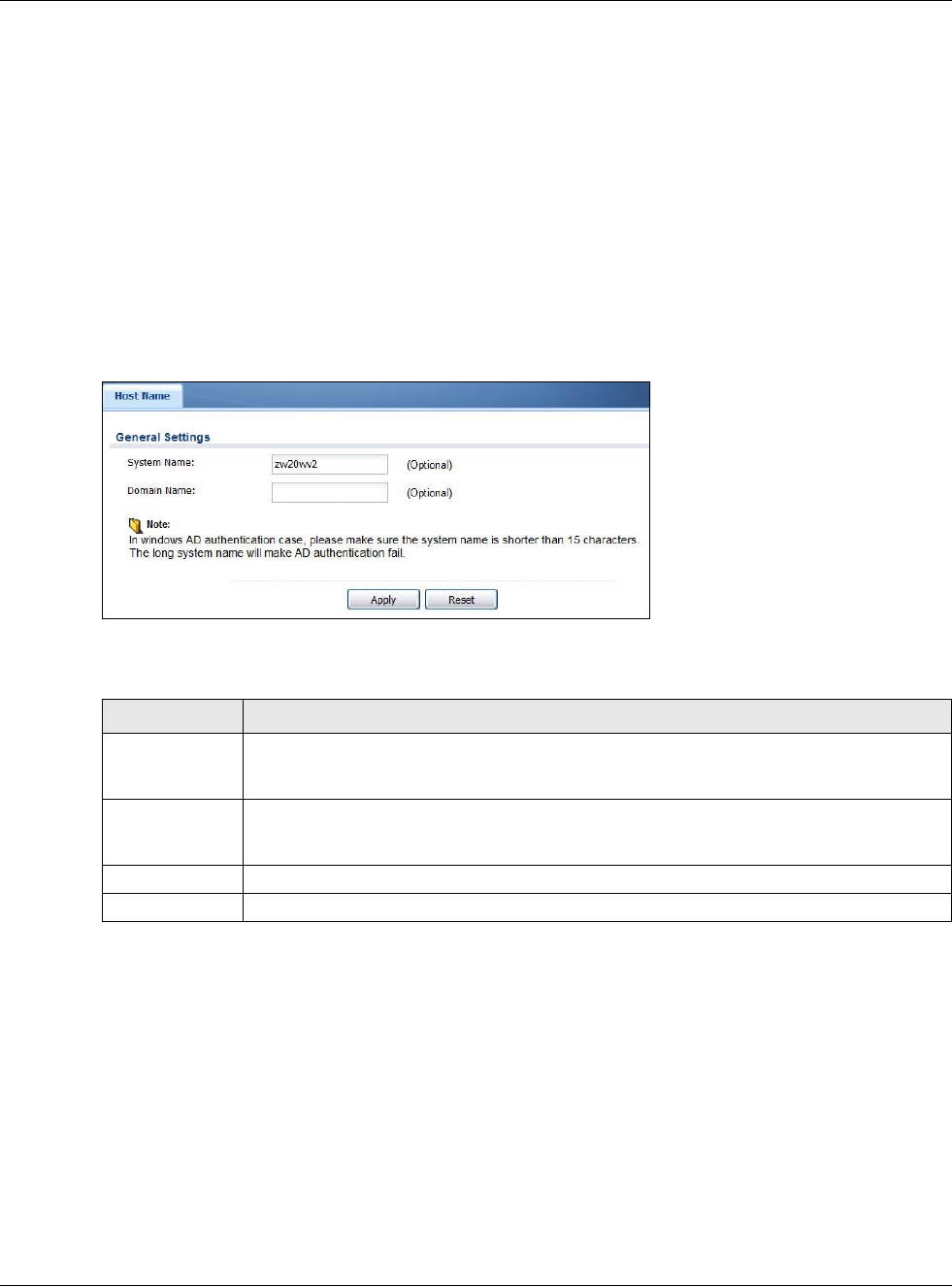
30.2 Host Name
A host name is the unique name by which a device is known on a network. Click Configuration >
System > Host Name to open the Host Name screen.
Figure 367 Configuration > System > Host Name
The following table describes the labels in this screen.
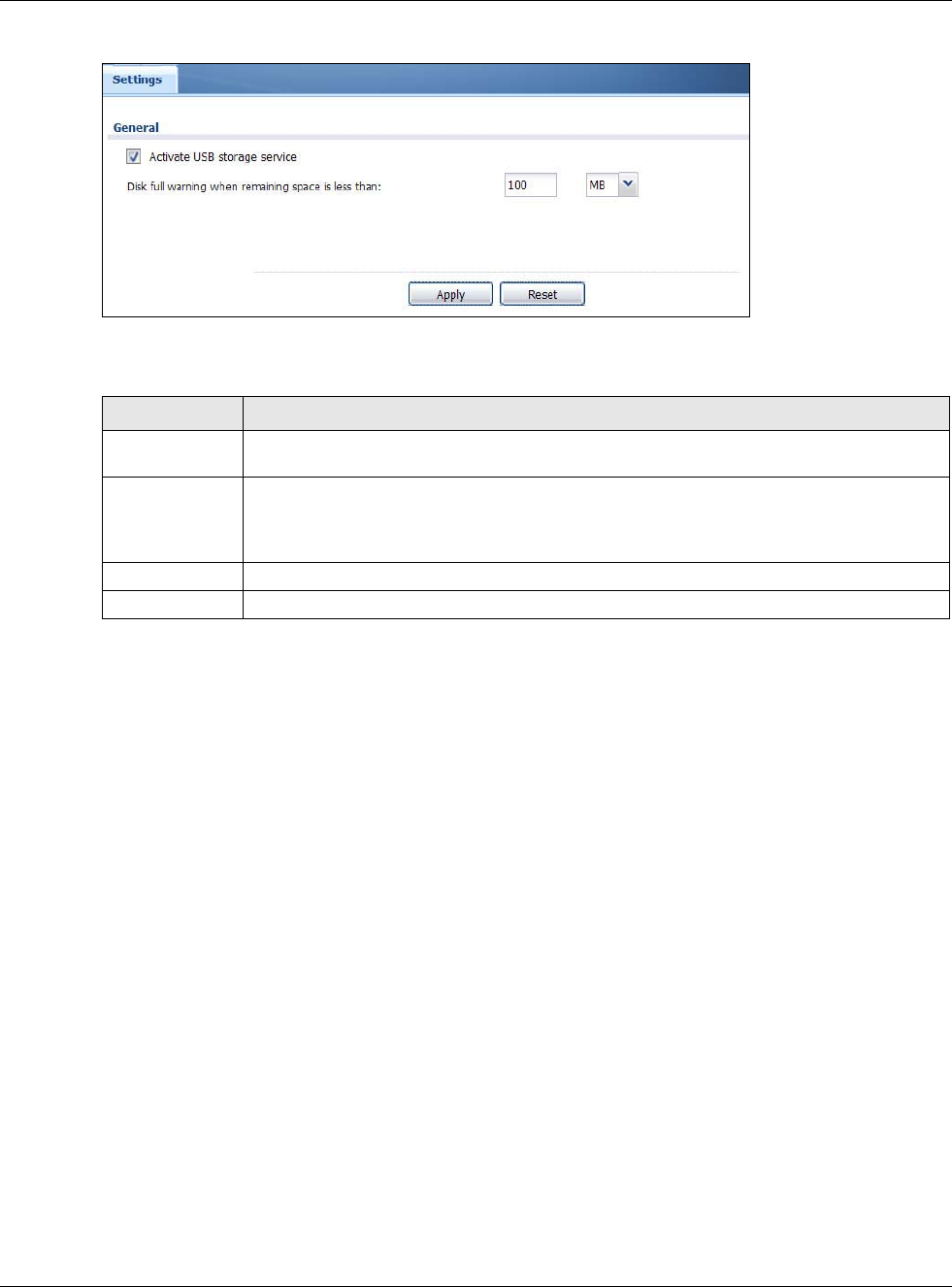
30.3 USB Storage
The USG can use a connected USB device to store the system log and other diagnostic information.
Use this screen to turn on this feature and set a disk full warning limit.
Note: Only connect one USB device. It must allow writing (it cannot be read-only) and
use the FAT16, FAT32, EXT2, or EXT3 file system.
Click Configuration > System > USB Storage to open the screen as shown next.
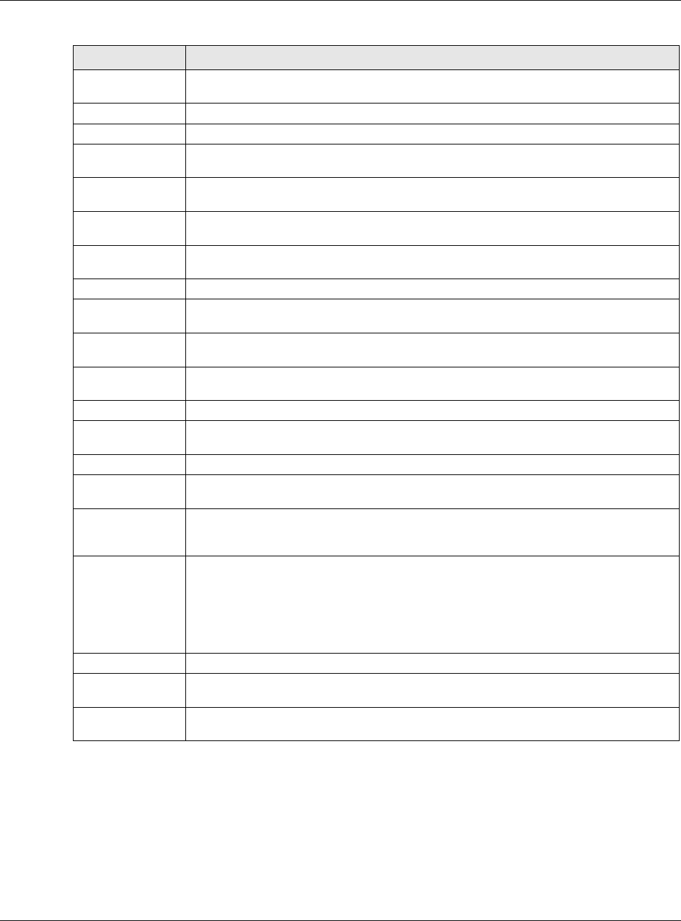
Table 229 Configuration > System > Host Name
LABEL DESCRIPTION
System Name Enter a descriptive name to identify your USG device. This name can be up to 64
alphanumeric characters long. Spaces are not allowed, but dashes (-) underscores (_) and
periods (.) are accepted.
Domain Name Enter the domain name (if you know it) here. This name is propagated to DHCP clients
connected to interfaces with the DHCP server enabled. This name can be up to 254
alphanumeric characters long. Spaces are not allowed, but dashes “-” are accepted.
Apply Click Apply to save your changes back to the USG.
Reset Click Reset to return the screen to its last-saved settings.
Chapter 30 System
USG20(W)-VPN Series User’s Guide
539
Figure 368 Configuration > System > USB Storage
The following table describes the labels in this screen.
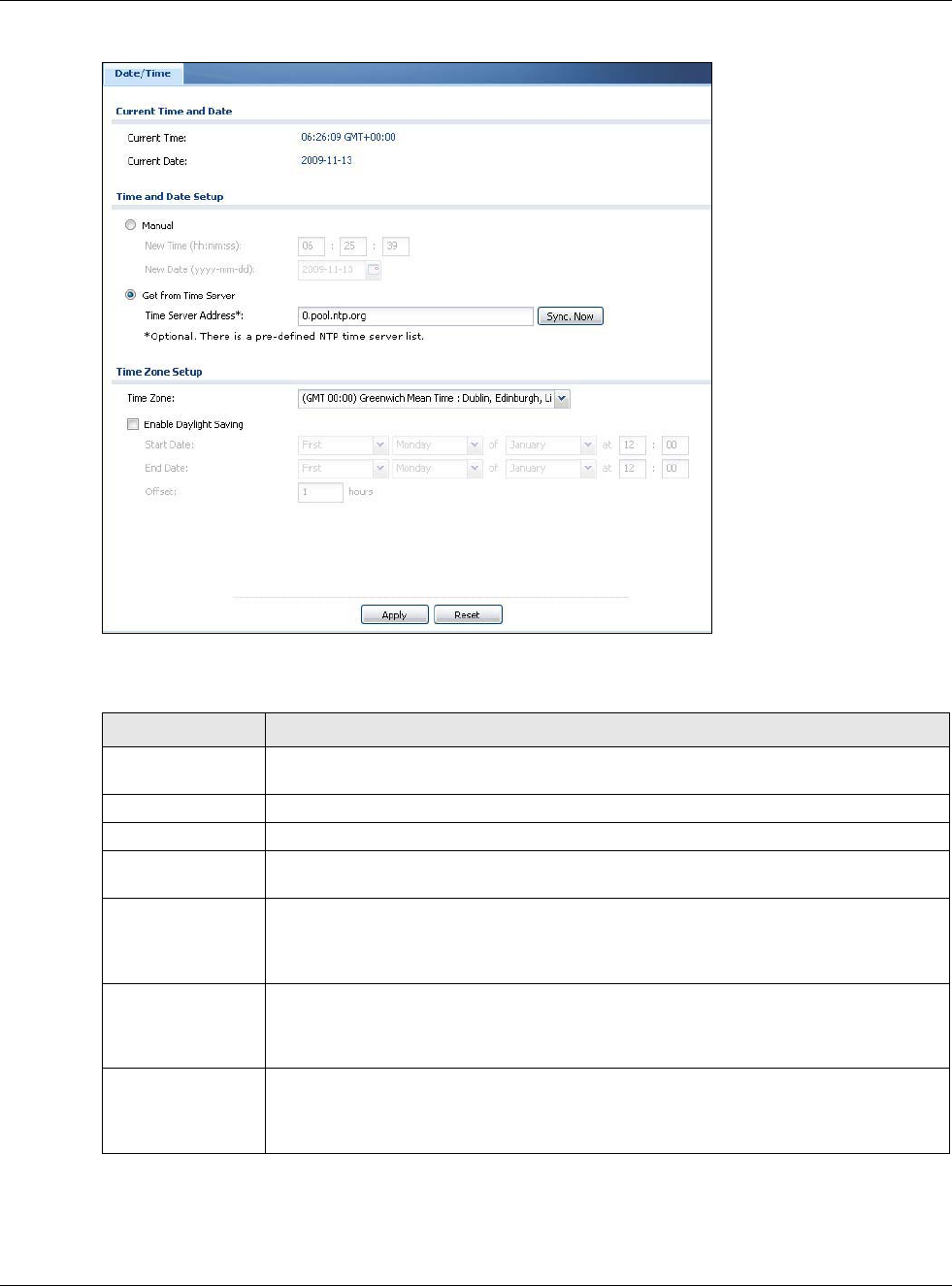
30.4 Date and Time
For effective scheduling and logging, the USG system time must be accurate. The USG’s Real Time
Chip (RTC) keeps track of the time and date. There is also a software mechanism to set the time
manually or get the current time and date from an external server.
To change your USG’s time based on your local time zone and date, click Configuration > System
> Date/Time. The screen displays as shown. You can manually set the USG’s time and date or
have the USG get the date and time from a time server.
Table 230 Configuration > System > USB Storage
LABEL DESCRIPTION
Activate USB
storage service
Select this if you want to use the connected USB device(s).
Disk full warning
when remaining
space is less
than
Set a number and select a unit (MB or %) to have the USG send a warning message when
the remaining USB storage space is less than the value you set here.
Apply Click Apply to save your changes back to the USG.
Reset Click Reset to return the screen to its last-saved settings.
Chapter 30 System
USG20(W)-VPN Series User’s Guide
540
Figure 369 Configuration > System > Date and Time
The following table describes the labels in this screen.
Table 231 Configuration > System > Date and Time
LABEL DESCRIPTION
Current Time and
Date
Current Time This field displays the present time of your USG.
Current Date This field displays the present date of your USG.
Time and Date
Setup
Manual Select this radio button to enter the time and date manually. If you configure a new time
and date, time zone and daylight saving at the same time, the time zone and daylight
saving will affect the new time and date you entered. When you enter the time settings
manually, the USG uses the new setting once you click Apply.
New Time (hh-mm-
ss)
This field displays the last updated time from the time server or the last time configured
manually.
When you set Time and Date Setup to Manual, enter the new time in this field and
then click Apply.
New Date
(yyyy-mm-dd)
This field displays the last updated date from the time server or the last date configured
manually.
When you set Time and Date Setup to Manual, enter the new date in this field and
then click Apply.
Chapter 30 System
USG20(W)-VPN Series User’s Guide
541
Get from Time
Server
Select this radio button to have the USG get the time and date from the time server you
specify below. The USG requests time and date settings from the time server under the
following circumstances.
• When the USG starts up.
• When you click Apply or Synchronize Now in this screen.
• 24-hour intervals after starting up.
Time Server
Address
Enter the IP address or URL of your time server. Check with your ISP/network
administrator if you are unsure of this information.
Sync. Now Click this button to have the USG get the time and date from a time server (see the
Time Server Address field). This also saves your changes (except the daylight saving
settings).
Time Zone Setup
Time Zone Choose the time zone of your location. This will set the time difference between your
time zone and Greenwich Mean Time (GMT).
Enable Daylight
Saving
Daylight saving is a period from late spring to early fall when many countries set their
clocks ahead of normal local time by one hour to give more daytime light in the evening.
Select this option if you use Daylight Saving Time.
Start Date Configure the day and time when Daylight Saving Time starts if you selected Enable
Daylight Saving. The at field uses the 24 hour format. Here are a couple of examples:
Daylight Saving Time starts in most parts of the United States on the second Sunday of
March. Each time zone in the United States starts using Daylight Saving Time at 2 A.M.
local time. So in the United States you would select Second, Sunday, March and type
2 in the at field.
Daylight Saving Time starts in the European Union on the last Sunday of March. All of
the time zones in the European Union start using Daylight Saving Time at the same
moment (1 A.M. GMT or UTC). So in the European Union you would select Last,
Sunday, March. The time you type in the at field depends on your time zone. In
Germany for instance, you would type 2 because Germany's time zone is one hour
ahead of GMT or UTC (GMT+1).
End Date Configure the day and time when Daylight Saving Time ends if you selected Enable
Daylight Saving. The at field uses the 24 hour format. Here are a couple of examples:
Daylight Saving Time ends in the United States on the first Sunday of November. Each
time zone in the United States stops using Daylight Saving Time at 2 A.M. local time. So
in the United States you would select First, Sunday, November and type 2 in the at
field.
Daylight Saving Time ends in the European Union on the last Sunday of October. All of
the time zones in the European Union stop using Daylight Saving Time at the same
moment (1 A.M. GMT or UTC). So in the European Union you would select Last,
Sunday, October. The time you type in the at field depends on your time zone. In
Germany for instance, you would type 2 because Germany's time zone is one hour
ahead of GMT or UTC (GMT+1).
Offset Specify how much the clock changes when daylight saving begins and ends.
Enter a number from 1 to 5.5 (by 0.5 increments).
For example, if you set this field to 3.5, a log occurred at 6 P.M. in local official time will
appear as if it had occurred at 10:30 P.M.
Apply Click Apply to save your changes back to the USG.
Reset Click Reset to return the screen to its last-saved settings.
Table 231 Configuration > System > Date and Time (continued)
LABEL DESCRIPTION
Chapter 30 System
USG20(W)-VPN Series User’s Guide
542
30.4.1 Pre-defined NTP Time Servers List
When you turn on the USG for the first time, the date and time start at 2003-01-01 00:00:00. The
USG then attempts to synchronize with one of the following pre-defined list of Network Time
Protocol (NTP) time servers.
The USG continues to use the following pre-defined list of NTP time servers if you do not specify a
time server or it cannot synchronize with the time server you specified.
When the USG uses the pre-defined list of NTP time servers, it randomly selects one server and
tries to synchronize with it. If the synchronization fails, then the USG goes through the rest of the
list in order from the first one tried until either it is successful or all the pre-defined NTP time
servers have been tried.
30.4.2 Time Server Synchronization
Click the Synchronize Now button to get the time and date from the time server you specified in
the Time Server Address field.
When the Please Wait... screen appears, you may have to wait up to one minute.
Figure 370 Synchronization in Process
The Current Time and Current Date fields will display the appropriate settings if the
synchronization is successful.
If the synchronization was not successful, a log displays in the View Log screen. Try re-configuring
the Date/Time screen.
To manually set the USG date and time.
1Click System > Date/Time.
2Select Manual under Time and Date Setup.
3Enter the USG’s time in the New Time field.
4Enter the USG’s date in the New Date field.
5Under Time Zone Setup, select your Time Zone from the list.
6As an option you can select the Enable Daylight Saving check box to adjust the USG clock for
daylight savings.
Table 232 Default Time Servers
0.pool.ntp.org
1.pool.ntp.org
2.pool.ntp.org
Chapter 30 System
USG20(W)-VPN Series User’s Guide
543
7Click Apply.
To get the USG date and time from a time server
1Click System > Date/Time.
2Select Get from Time Server under Time and Date Setup.
3Under Time Zone Setup, select your Time Zone from the list.
4As an option you can select the Enable Daylight Saving check box to adjust the USG clock for
daylight savings.
5Under Time and Date Setup, enter a Time Server Address (Table 232 on page 542).
6Click Apply.
30.5 Console Port Speed
This section shows you how to set the console port speed when you connect to the USG via the
console port using a terminal emulation program.
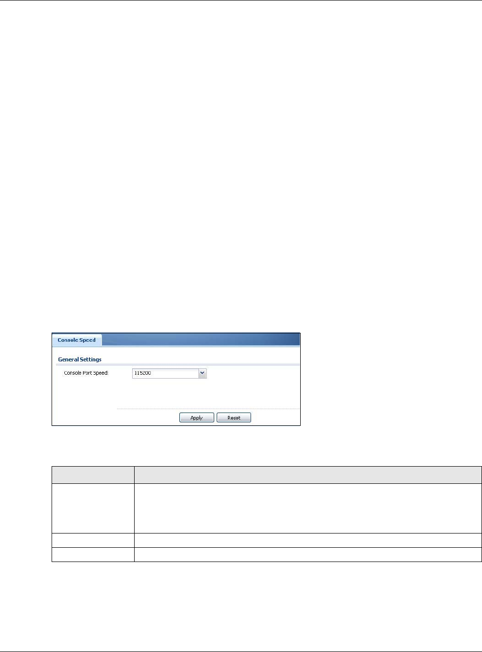
Click Configuration > System > Console Speed to open the Console Speed screen.
Figure 371 Configuration > System > Console Speed
The following table describes the labels in this screen.
Table 233 Configuration > System > Console Speed
LABEL DESCRIPTION
Console Port Speed Use the drop-down list box to change the speed of the console port. Your USG supports
9600, 19200, 38400, 57600, and 115200 bps (default) for the console port.
The Console Port Speed applies to a console port connection using terminal emulation
software and NOT the Console in the USG Web Configurator Status screen.
Apply Click Apply to save your changes back to the USG.
Reset Click Reset to return the screen to its last-saved settings.

Chapter 30 System
USG20(W)-VPN Series User’s Guide
544
30.6 DNS Overview
DNS (Domain Name System) is for mapping a domain name to its corresponding IP address and
vice versa. The DNS server is extremely important because without it, you must know the IP
address of a machine before you can access it.
30.6.1 DNS Server Address Assignment
The USG can get the DNS server addresses in the following ways.
• The ISP tells you the DNS server addresses, usually in the form of an information sheet, when
you sign up. If your ISP gives you DNS server addresses, manually enter them in the DNS server
fields.
• If your ISP dynamically assigns the DNS server IP addresses (along with the USG’s WAN IP
address), set the DNS server fields to get the DNS server address from the ISP.
• You can manually enter the IP addresses of other DNS servers.
30.6.2 Configuring the DNS Screen
Click Configuration > System > DNS to change your USG’s DNS settings. Use the DNS screen to
configure the USG to use a DNS server to resolve domain names for USG system features like VPN,
DDNS and the time server. You can also configure the USG to accept or discard DNS queries. Use
the Network > Interface screens to configure the DNS server information that the USG sends to
the specified DHCP client devices.
A name query begins at a client computer and is passed to a resolver, a DNS client service, for
resolution. The USG can be a DNS client service. The USG can resolve a DNS query locally using
cached Resource Records (RR) obtained from a previous query (and kept for a period of time). If
the USG does not have the requested information, it can forward the request to DNS servers. This
is known as recursion.
The USG can ask a DNS server to use recursion to resolve its DNS client requests. If recursion on
the USG or a DNS server is disabled, they cannot forward DNS requests for resolution.
A Domain Name Server (DNS) amplification attack is a kind of Distributed Denial of Service (DDoS)
attack that uses publicly accessible open DNS servers to flood a victim with DNS response traffic.
An open DNS server is a DNS server which is willing to resolve recursive DNS queries from anyone
on the Internet.
In a DNS amplification attack, an attacker sends a DNS name lookup request to an open DNS
server with the source address spoofed as the victim’s address. When the DNS server sends the
DNS record response, it is sent to the victim. Attackers can request as much information as possible
to maximize the amplification effect.
Configure the Security Option Control section in the Configuration > System > DNS screen
(click Show Advanced Settings to display it) if you suspect the USG is being used (either by
hackers or by a corrupted open DNS server) in a DNS amplification attack.
Chapter 30 System
USG20(W)-VPN Series User’s Guide
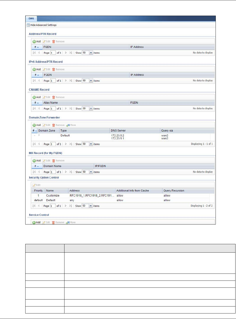
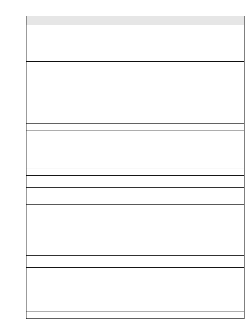
545
Figure 372 Configuration > System > DNS
The following table describes the labels in this screen.
Table 234 Configuration > System > DNS
LABEL DESCRIPTION
Address/PTR
Record
This record specifies the mapping of a Fully-Qualified Domain Name (FQDN) to an IP
address. An FQDN consists of a host and domain name. For example, www.zyxel.com.tw
is a fully qualified domain name, where “www” is the host, “zyxel” is the third-level
domain, “com” is the second-level domain, and “tw” is the top level domain.
Add Click this to create a new entry.
Edit Double-click an entry or select it and click Edit to be able to modify the entry’s settings.
Remove To remove an entry, select it and click Remove. The USG confirms you want to remove it
before doing so. Note that subsequent entries move up by one when you take this action.
#This is the index number of the address/PTR record.
FQDN This is a host’s fully qualified domain name.
Chapter 30 System
USG20(W)-VPN Series User’s Guide
546
IP Address This is the IP address of a host.
CNAME Record This record specifies an alias for a FQDN. Use this record to bind all subdomains with the
same IP address as the FQDN without having to update each one individually, which
increases chance for errors. See CNAME Record (Section 30.6.6 on page 548) for more
details.
Add Click this to create a new entry.
Edit Double-click an entry or select it and click Edit to be able to modify the entry’s settings.
Remove To remove an entry, select it and click Remove. The USG confirms you want to remove it
before doing so. Note that subsequent entries move up by one when you take this action.
#This is the index number of the domain zone forwarder record. The ordering of your rules
is important as rules are applied in sequence.
A hyphen (-) displays for the default domain zone forwarder record. The default record is
not configurable. The USG uses this default record if the domain zone that needs to be
resolved does not match any of the other domain zone forwarder records.
Alias Name Enter an Alias name. Use “*.” as prefix for a wildcard domain name. For example,
*.example.com.
FQDN Enter the Fully Qualified Domain Name (FQDN).
Domain Zone
Forwarder
This specifies a DNS server’s IP address. The USG can query the DNS server to resolve
domain zones for features like VPN, DDNS and the time server.
When the USG needs to resolve a domain zone, it checks it against the domain zone
forwarder entries in the order that they appear in this list.
Add Click this to create a new entry. Select an entry and click Add to create a new entry after
the selected entry.
Edit Double-click an entry or select it and click Edit to be able to modify the entry’s settings.
Remove To remove an entry, select it and click Remove. The USG confirms you want to remove it
before doing so. Note that subsequent entries move up by one when you take this action.
Move To change an entry’s position in the numbered list, select the method and click Move to
display a field to type a number for where you want to put it and press [ENTER] to move
the rule to the number that you typed.
#This is the index number of the domain zone forwarder record. The ordering of your rules
is important as rules are applied in sequence.
A hyphen (-) displays for the default domain zone forwarder record. The default record is
not configurable. The USG uses this default record if the domain zone that needs to be
resolved does not match any of the other domain zone forwarder records.
Domain Zone A domain zone is a fully qualified domain name without the host. For example,
zyxel.com.tw is the domain zone for the www.zyxel.com.tw fully qualified domain name.
A “*” means all domain zones.
Type This displays whether the DNS server IP address is assigned by the ISP dynamically
through a specified interface or configured manually (User-Defined).
DNS Server This is the IP address of a DNS server. This field displays N/A if you have the USG get a
DNS server IP address from the ISP dynamically but the specified interface is not active.
Query Via This is the interface through which the USG sends DNS queries to the entry’s DNS server.
If the USG connects through a VPN tunnel, tunnel displays.
MX Record (for My
FQDN)
A MX (Mail eXchange) record identifies a mail server that handles the mail for a
particular domain.
Add Click this to create a new entry.
Edit Double-click an entry or select it and click Edit to be able to modify the entry’s settings.
Table 234 Configuration > System > DNS (continued)
LABEL DESCRIPTION
Chapter 30 System
USG20(W)-VPN Series User’s Guide
547
30.6.3 Address Record
An address record contains the mapping of a Fully-Qualified Domain Name (FQDN) to an IP
address. An FQDN consists of a host and domain name. For example, www.zyxel.com is a fully
qualified domain name, where “www” is the host, “zyxel” is the second-level domain, and “com” is
the top level domain. mail.myZyXEL.com.tw is also a FQDN, where “mail” is the host, “myZyXEL” is
the third-level domain, “com” is the second-level domain, and “tw” is the top level domain.
Remove To remove an entry, select it and click Remove. The USG confirms you want to remove it
before doing so. Note that subsequent entries move up by one when you take this action.
#This is the index number of the MX record.
Domain Name This is the domain name where the mail is destined for.
IP/FQDN This is the IP address or Fully-Qualified Domain Name (FQDN) of a mail server that
handles the mail for the domain specified in the field above.
Security Option
Control
Click Show Advanced Settings to display this part of the screen. There are two control
policies: Default and Customize.
Edit Click either control policy and then click this button to change allow or deny actions for
Query Recursion and Additional Info from Cache.
Priority The Customize control policy is checked first and if an address object match is not
found, the Default control policy is checked.
Name You may change the name of the Customize control policy.
Address These are the object addresses used in the control policy. RFC1918 refers to private IP
address ranges. It can be modified in Object > Address.
Additional Info
from Cache This displays if the USG is allowed or denied to cache Resource Records (RR) obtained
from previous DNS queries.
Query
Recursion This displays if the USG is allowed or denied to forward DNS client requests to DNS
servers for resolution.
Service Control This specifies from which computers and zones you can send DNS queries to the USG.
Add Click this to create a new entry. Select an entry and click Add to create a new entry after
the selected entry.
Edit Double-click an entry or select it and click Edit to be able to modify the entry’s settings.
Remove To remove an entry, select it and click Remove. The USG confirms you want to remove it
before doing so. Note that subsequent entries move up by one when you take this action.
Move To change an entry’s position in the numbered list, select the method and click Move to
display a field to type a number for where you want to put it and press [ENTER] to move
the rule to the number that you typed.
#This the index number of the service control rule. The ordering of your rules is important
as rules are applied in sequence.
The entry with a hyphen (-) instead of a number is the USG’s (non-configurable) default
policy. The USG applies this to traffic that does not match any other configured rule. It is
not an editable rule. To apply other behavior, configure a rule that traffic will match so
the USG will not have to use the default policy.
Zone This is the zone on the USG the user is allowed or denied to access.
Address This is the object name of the IP address(es) with which the computer is allowed or
denied to send DNS queries.
Action This displays whether the USG accepts DNS queries from the computer with the IP
address specified above through the specified zone (Accept) or discards them (Deny).
Table 234 Configuration > System > DNS (continued)
LABEL DESCRIPTION
Chapter 30 System
USG20(W)-VPN Series User’s Guide
548
The USG allows you to configure address records about the USG itself or another device. This way
you can keep a record of DNS names and addresses that people on your network may use
frequently. If the USG receives a DNS query for an FQDN for which the USG has an address record,
the USG can send the IP address in a DNS response without having to query a DNS name server.
30.6.4 PTR Record
A PTR (pointer) record is also called a reverse record or a reverse lookup record. It is a mapping of
an IP address to a domain name.
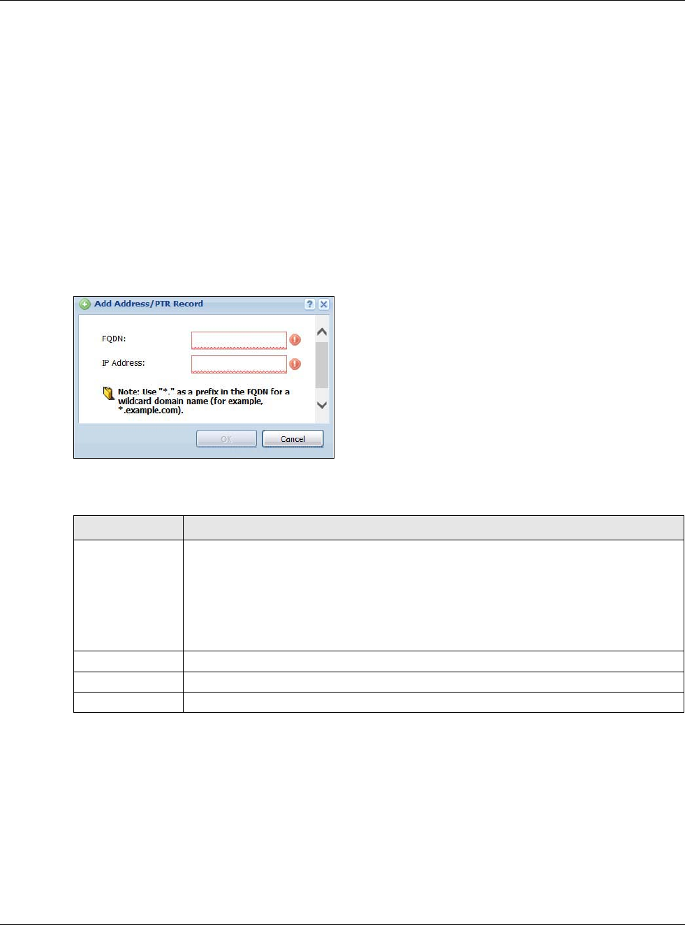
30.6.5 Adding an Address/PTR Record
Click the Add icon in the Address/PTR Record table to add an address/PTR record.
Figure 373 Configuration > System > DNS > Address/PTR Record Edit
The following table describes the labels in this screen.
30.6.6 CNAME Record
A Canonical Name Record or CNAME record is a type of resource record in the Domain Name
System (DNS) that specifies that the domain name is an alias of another, canonical domain name.
This allows users to set up a record for a domain name which translates to an IP address, in other
words, the domain name is an alias of another. This record also binds all the subdomains to the
same IP address without having to create a record for each, so when the IP address is changed, all
subdomain’s IP address is updated as well, with one edit to the record.
Table 235 Configuration > System > DNS > Address/PTR Record Edit
LABEL DESCRIPTION
FQDN Type a Fully-Qualified Domain Name (FQDN) of a server. An FQDN starts with a host
name and continues all the way up to the top-level domain name. For example,
www.zyxel.com.tw is a fully qualified domain name, where “www” is the host, “zyxel” is
the third-level domain, “com” is the second-level domain, and “tw” is the top level
domain. Underscores are not allowed.
Use "*." as a prefix in the FQDN for a wildcard domain name (for example,
*.example.com).
IP Address Enter the IP address of the host in dotted decimal notation.
OK Click OK to save your customized settings and exit this screen.
Cancel Click Cancel to exit this screen without saving
Chapter 30 System
USG20(W)-VPN Series User’s Guide
549
For example, the domain name zyxel.com is hooked up to a record named A which translates it to
11.22.33.44. You also have several subdomains, like mail.zyxel.com, ftp.zyxel.com and you want
this subdomain to point to your main domain zyxel.com. Edit the IP Address in record A and all
subdomains will follow automatically. This eliminates chances for errors and increases efficiency in
DNS management.
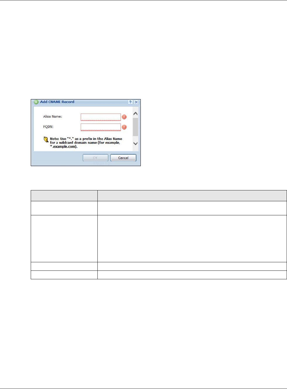
30.6.7 Adding a CNAME Record
Click the Add icon in the CNAME Record table to add a record. Use “*.” as a prefix for a wildcard
domain name. For example *.zyxel.com.
Figure 374 Configuration > System > DNS > CNAME Record > Add
The following table describes the labels in this screen.
30.6.8 Domain Zone Forwarder
A domain zone forwarder contains a DNS server’s IP address. The USG can query the DNS server to
resolve domain zones for features like VPN, DDNS and the time server. A domain zone is a fully
qualified domain name without the host. For example, zyxel.com.tw is the domain zone for the
www.zyxel.com.tw fully qualified domain name.
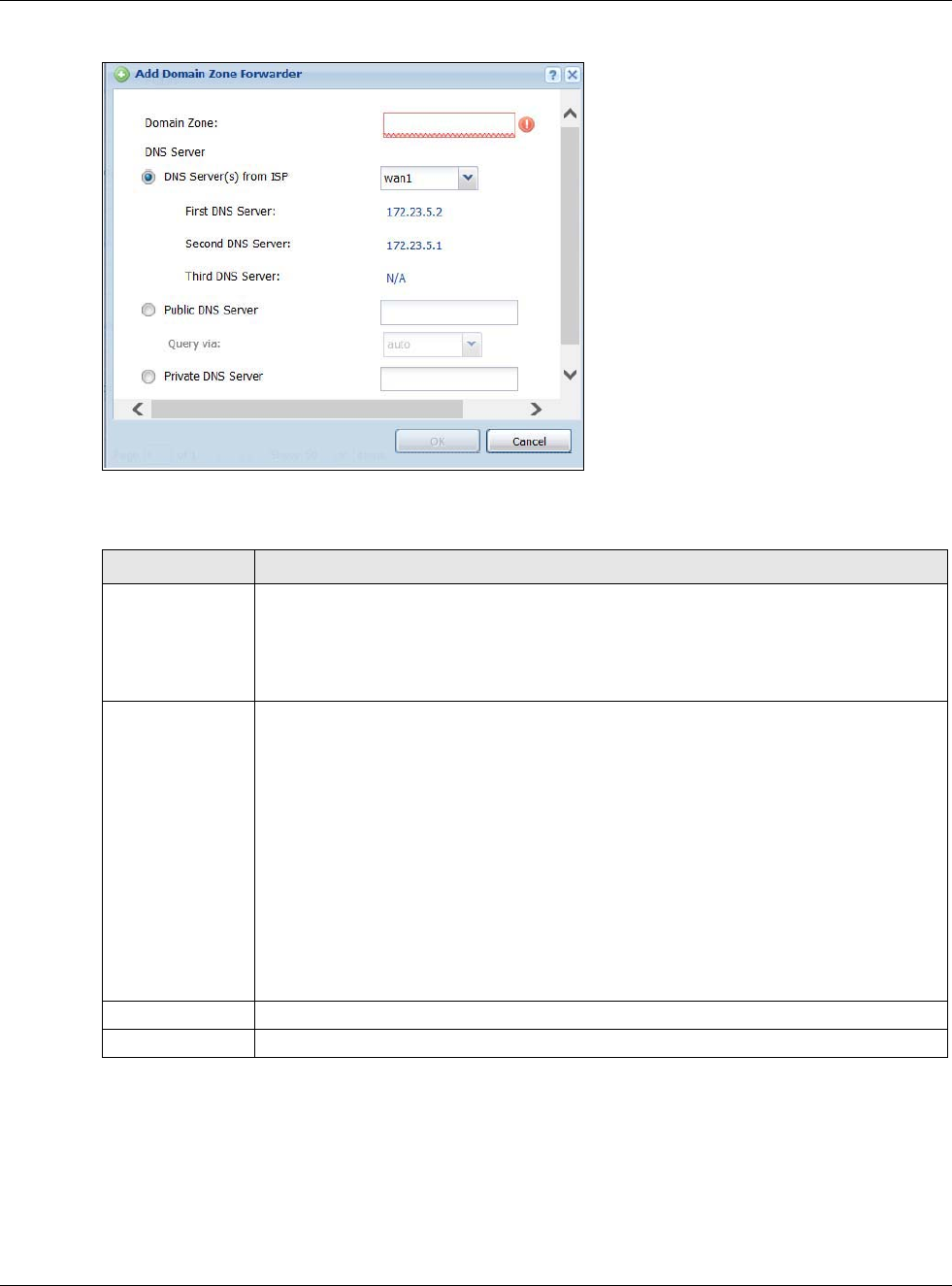
30.6.9 Adding a Domain Zone Forwarder
Click the Add icon in the Domain Zone Forwarder table to add a domain zone forwarder record.
Table 236 Configuration > System > DNS > CNAME Record > Add
LABEL DESCRIPTION
Alias name Enter an Alias Name. Use "*." as a prefix in the Alias name for a wildcard domain
name (for example, *.example.com).
FQDN Type a Fully-Qualified Domain Name (FQDN) of a server. An FQDN starts with a
host name and continues all the way up to the top-level domain name. For
example, www.zyxel.com.tw is a fully qualified domain name, where “www” is
the host, “zyxel” is the third-level domain, “com” is the second-level domain,
and “tw” is the top level domain. Underscores are not allowed.
Use "*." as a prefix in the FQDN for a wildcard domain name (for example,
*.example.com).
OK Click OK to save your customized settings and exit this screen.
Cancel Click Cancel to exit this screen without saving.
Chapter 30 System
USG20(W)-VPN Series User’s Guide
550
Figure 375 Configuration > System > DNS > Domain Zone Forwarder Add
The following table describes the labels in this screen.
30.6.10 MX Record
A MX (Mail eXchange) record indicates which host is responsible for the mail for a particular
domain, that is, controls where mail is sent for that domain. If you do not configure proper MX
records for your domain or other domain, external e-mail from other mail servers will not be able to
be delivered to your mail server and vice versa. Each host or domain can have only one MX record,
that is, one domain is mapping to one host.
Table 237 Configuration > System > DNS > Domain Zone Forwarder Add
LABEL DESCRIPTION
Domain Zone A domain zone is a fully qualified domain name without the host. For example,
zyxel.com.tw is the domain zone for the www.zyxel.com.tw fully qualified domain name.
For example, whenever the USG receives needs to resolve a zyxel.com.tw domain name,
it can send a query to the recorded name server IP address.
Enter * if all domain zones are served by the specified DNS server(s).
DNS Server Select DNS Server(s) from ISP if your ISP dynamically assigns DNS server
information. You also need to select an interface through which the ISP provides the DNS
server IP address(es). The interface should be activated and set to be a DHCP client. The
fields below display the (read-only) DNS server IP address(es) that the ISP assigns. N/A
displays for any DNS server IP address fields for which the ISP does not assign an IP
address.
Select Public DNS Server if you have the IP address of a DNS server. Enter the DNS
server's IP address in the field to the right. The USG must be able to connect to the DNS
server without using a VPN tunnel. The DNS server could be on the Internet or one of the
USG’s local networks. You cannot use 0.0.0.0. Use the Query via field to select the
interface through which the USG sends DNS queries to a DNS server.
Select Private DNS Server if you have the IP address of a DNS server to which the USG
connects through a VPN tunnel. Enter the DNS server's IP address in the field to the
right. You cannot use 0.0.0.0.
OK Click OK to save your customized settings and exit this screen.
Cancel Click Cancel to exit this screen without saving
Chapter 30 System
USG20(W)-VPN Series User’s Guide
551
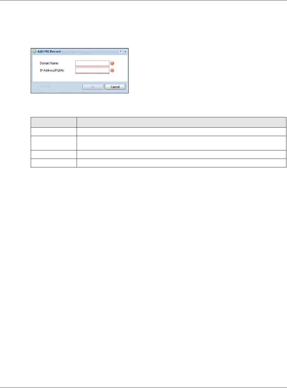
30.6.11 Adding a MX Record
Click the Add icon in the MX Record table to add a MX record.
Figure 376 Configuration > System > DNS > MX Record Add
The following table describes the labels in this screen.
30.6.12 Security Option Control
Configure the Security Option Control section in the Configuration > System > DNS screen
(click Show Advanced Settings to display it) if you suspect the USG is being used by hackers in a
DNS amplification attack.
One possible strategy would be to deny Query Recursion and Additional Info from Cache in the
default policy and allow Query Recursion and Additional Info from Cache only from trusted
DNS servers identified by address objects and added as members in the customized policy.
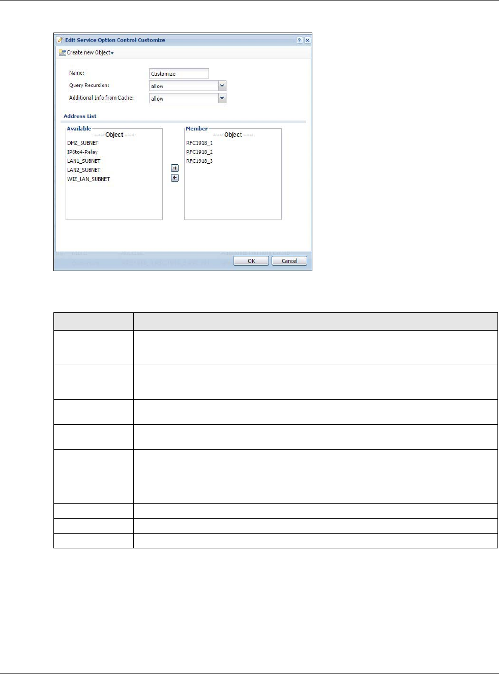
30.6.13 Editing a Security Option Control
Click a control policy and then click Edit to change allow or deny actions for Query Recursion
and Additional Info from Cache.
Table 238 Configuration > System > DNS > MX Record Add
LABEL DESCRIPTION
Domain Name Enter the domain name where the mail is destined for.
IP Address/FQDN Enter the IP address or Fully-Qualified Domain Name (FQDN) of a mail server that
handles the mail for the domain specified in the field above.
OK Click OK to save your customized settings and exit this screen.
Cancel Click Cancel to exit this screen without saving
Chapter 30 System
USG20(W)-VPN Series User’s Guide
552
Figure 377 Configuration > System > DNS > Security Option Control Edit (Customize)
The following table describes the labels in this screen.
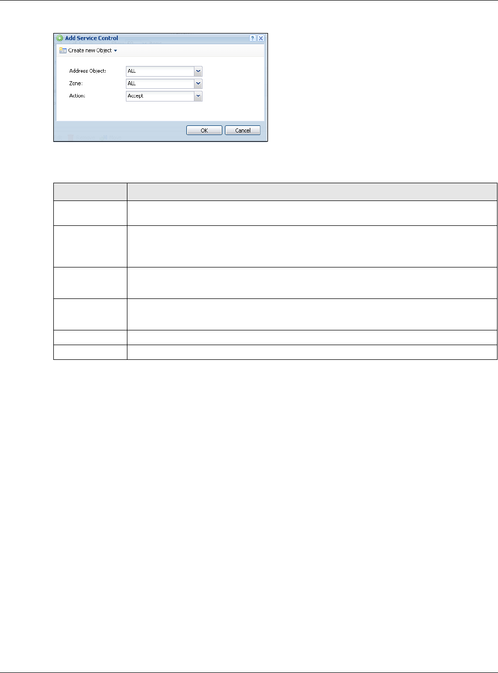
30.6.14 Adding a DNS Service Control Rule
Click the Add icon in the Service Control table to add a service control rule.
Table 239 Configuration > System > DNS > Security Option Control Edit (Customize)
LABEL DESCRIPTION
Name You may change the name for the customized security option control policy. The
customized security option control policy is checked first and if an address object match is
not found, the Default control policy is checked
Query Recursion Choose if the USG is allowed or denied to forward DNS client requests to DNS servers for
resolution. This can apply to specific open DNS servers using the address objects in a
customized rule.
Additional Info
from Cache
Choose if the USG is allowed or denied to cache Resource Records (RR) obtained from
previous DNS queries.
Address List Specifiying address objects is not available in the default policy as all addresses are
included.
Available This box displays address objects created in Object > Address. Select one (or more),
and click the > arrow to have it (them) join the Member list of address objects that will
apply to this rule. For example, you could specifiy an open DNS server suspect of sending
compromised resource records by adding an address object for that server to the
member list.
Member This box displays address objects that will apply to this rule.
OK Click OK to save your customized settings and exit this screen.
Cancel Click Cancel to exit this screen without saving
Chapter 30 System
USG20(W)-VPN Series User’s Guide
553
Figure 378 Configuration > System > DNS > Service Control Rule Add
The following table describes the labels in this screen.
30.7 WWW Overview
The following figure shows secure and insecure management of the USG coming in from the WAN.
HTTPS and SSH access are secure. HTTP and Telnet access are not secure.
Note: To allow the USG to be accessed from a specified computer using a service, make
sure you do not have a service control rule or to-USG security policy rule to block
that traffic.
To stop a service from accessing the USG, clear Enable in the corresponding service screen.
30.7.1 Service Access Limitations
A service cannot be used to access the USG when:
1You have disabled that service in the corresponding screen.
2The allowed IP address (address object) in the Service Control table does not match the client IP
address (the USG disallows the session).
Table 240 Configuration > System > DNS > Service Control Rule Add
LABEL DESCRIPTION
Create new
Object
Use this to configure any new settings objects that you need to use in this screen.
Address Object Select ALL to allow or deny any computer to send DNS queries to the USG.
Select a predefined address object to just allow or deny the computer with the IP address
that you specified to send DNS queries to the USG.
Zone Select ALL to allow or prevent DNS queries through any zones.
Select a predefined zone on which a DNS query to the USG is allowed or denied.
Action Select Accept to have the USG allow the DNS queries from the specified computer.
Select Deny to have the USG reject the DNS queries from the specified computer.
OK Click OK to save your customized settings and exit this screen.
Cancel Click Cancel to exit this screen without saving

Chapter 30 System
USG20(W)-VPN Series User’s Guide
554
3The IP address (address object) in the Service Control table is not in the allowed zone or the
action is set to Deny.
4There is a security policy rule that blocks it.
30.7.2 System Timeout
There is a lease timeout for administrators. The USG automatically logs you out if the management
session remains idle for longer than this timeout period. The management session does not time
out when a statistics screen is polling.
Each user is also forced to log in the USG for authentication again when the reauthentication time
expires.
You can change the timeout settings in the User/Group screens.
30.7.3 HTTPS
You can set the USG to use HTTP or HTTPS (HTTPS adds security) for Web Configurator sessions.
Specify which zones allow Web Configurator access and from which IP address the access can
come.
HTTPS (HyperText Transfer Protocol over Secure Socket Layer, or HTTP over SSL) is a web protocol
that encrypts and decrypts web pages. Secure Socket Layer (SSL) is an application-level protocol
that enables secure transactions of data by ensuring confidentiality (an unauthorized party cannot
read the transferred data), authentication (one party can identify the other party) and data
integrity (you know if data has been changed).
It relies upon certificates, public keys, and private keys.
HTTPS on the USG is used so that you can securely access the USG using the Web Configurator. The
SSL protocol specifies that the HTTPS server (the USG) must always authenticate itself to the
HTTPS client (the computer which requests the HTTPS connection with the USG), whereas the
HTTPS client only should authenticate itself when the HTTPS server requires it to do so (select
Authenticate Client Certificates in the WWW screen). Authenticate Client Certificates is
optional and if selected means the HTTPS client must send the USG a certificate. You must apply for
a certificate for the browser from a CA that is a trusted CA on the USG.
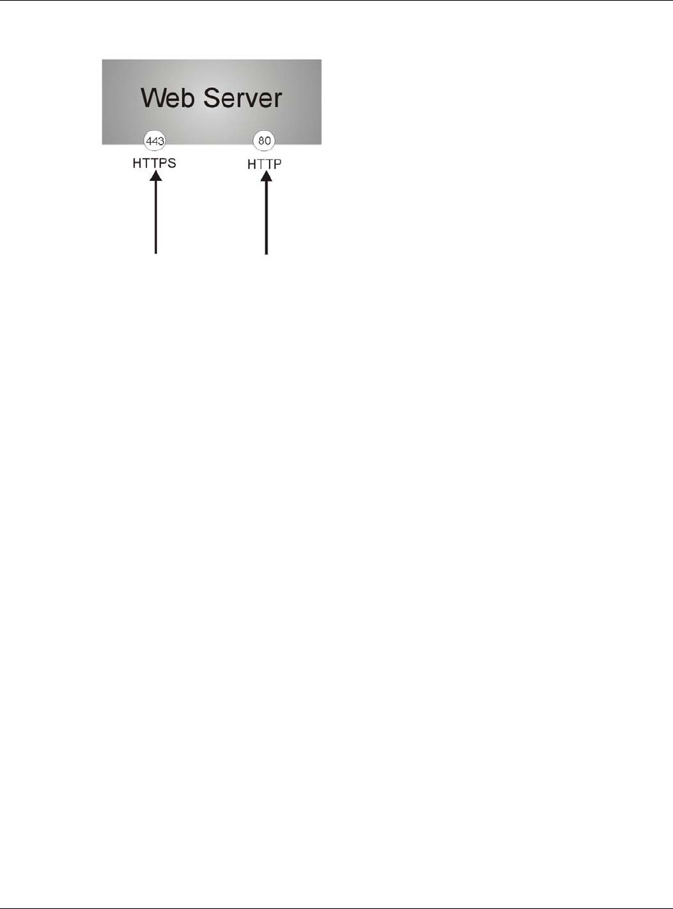
Please refer to the following figure.
1HTTPS connection requests from an SSL-aware web browser go to port 443 (by default) on the
USG’s web server.
2HTTP connection requests from a web browser go to port 80 (by default) on the USG’s web server.
Chapter 30 System
USG20(W)-VPN Series User’s Guide
555
Figure 379 HTTP/HTTPS Implementation
Note: If you disable HTTP in the WWW screen, then the USG blocks all HTTP connection
attempts.
30.7.4 Configuring WWW Service Control
Click Configuration > System > WWW to open the WWW screen. Use this screen to specify
from which zones you can access the USG using HTTP or HTTPS. You can also specify which IP
addresses the access can come from.
Note: Admin Service Control deals with management access (to the Web Configurator).
User Service Control deals with user access to the USG (logging into SSL VPN for
example).
Chapter 30 System
USG20(W)-VPN Series User’s Guide
556
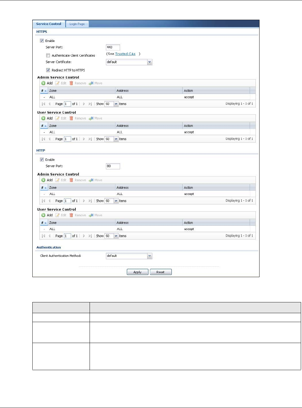
Figure 380 Configuration > System > WWW > Service Control
The following table describes the labels in this screen.
Table 241 Configuration > System > WWW > Service Control
LABEL DESCRIPTION
HTTPS
Enable Select the check box to allow or disallow the computer with the IP address that
matches the IP address(es) in the Service Control table to access the USG Web
Configurator using secure HTTPs connections.
Server Port The HTTPS server listens on port 443 by default. If you change the HTTPS server port
to a different number on the USG, for example 8443, then you must notify people
who need to access the USG Web Configurator to use “https://USG IP Address:8443”
as the URL.
Chapter 30 System
USG20(W)-VPN Series User’s Guide
557
Authenticate Client
Certificates
Select Authenticate Client Certificates (optional) to require the SSL client to
authenticate itself to the USG by sending the USG a certificate. To do that the SSL
client must have a CA-signed certificate from a CA that has been imported as a
trusted CA on the USG (see Section 30.7.7.5 on page 564 on importing certificates
for details).
Server Certificate Select a certificate the HTTPS server (the USG) uses to authenticate itself to the
HTTPS client. You must have certificates already configured in the My Certificates
screen.
Redirect HTTP to
HTTPS
To allow only secure Web Configurator access, select this to redirect all HTTP
connection requests to the HTTPS server.
Admin/User Service
Control
Admin Service Control specifies from which zones an administrator can use HTTPS
to manage the USG (using the Web Configurator). You can also specify the IP
addresses from which the administrators can manage the USG.
User Service Control specifies from which zones a user can use HTTPS to log into
the USG (to log into SSL VPN for example). You can also specify the IP addresses
from which the users can access the USG.
Add Click this to create a new entry. Select an entry and click Add to create a new entry
after the selected entry.
Edit Double-click an entry or select it and click Edit to be able to modify the entry’s
settings.
Remove To remove an entry, select it and click Remove. The USG confirms you want to
remove it before doing so. Note that subsequent entries move up by one when you
take this action.
Move To change an entry’s position in the numbered list, select the method and click Move
to display a field to type a number for where you want to put it and press [ENTER] to
move the rule to the number that you typed.
#This is the index number of the service control rule.
The entry with a hyphen (-) instead of a number is the USG’s (non-configurable)
default policy. The USG applies this to traffic that does not match any other
configured rule. It is not an editable rule. To apply other behavior, configure a rule
that traffic will match so the USG will not have to use the default policy.
Zone This is the zone on the USG the user is allowed or denied to access.
Address This is the object name of the IP address(es) with which the computer is allowed or
denied to access.
Action This displays whether the computer with the IP address specified above can access
the USG zone(s) configured in the Zone field (Accept) or not (Deny).
HTTP
Enable Select the check box to allow or disallow the computer with the IP address that
matches the IP address(es) in the Service Control table to access the USG Web
Configurator using HTTP connections.
Server Port You may change the server port number for a service if needed, however you must
use the same port number in order to use that service to access the USG.
Admin/User Service
Control
Admin Service Control specifies from which zones an administrator can use HTTP to
manage the USG (using the Web Configurator). You can also specify the IP addresses
from which the administrators can manage the USG.
User Service Control specifies from which zones a user can use HTTP to log into the
USG (to log into SSL VPN for example). You can also specify the IP addresses from
which the users can access the USG.
Add Click this to create a new entry. Select an entry and click Add to create a new entry
after the selected entry.
Table 241 Configuration > System > WWW > Service Control (continued)
LABEL DESCRIPTION
Chapter 30 System
USG20(W)-VPN Series User’s Guide
558
30.7.5 Service Control Rules
Click Add or Edit in the Service Control table in a WWW, SSH, Telnet, FTP or SNMP screen to
add a service control rule.
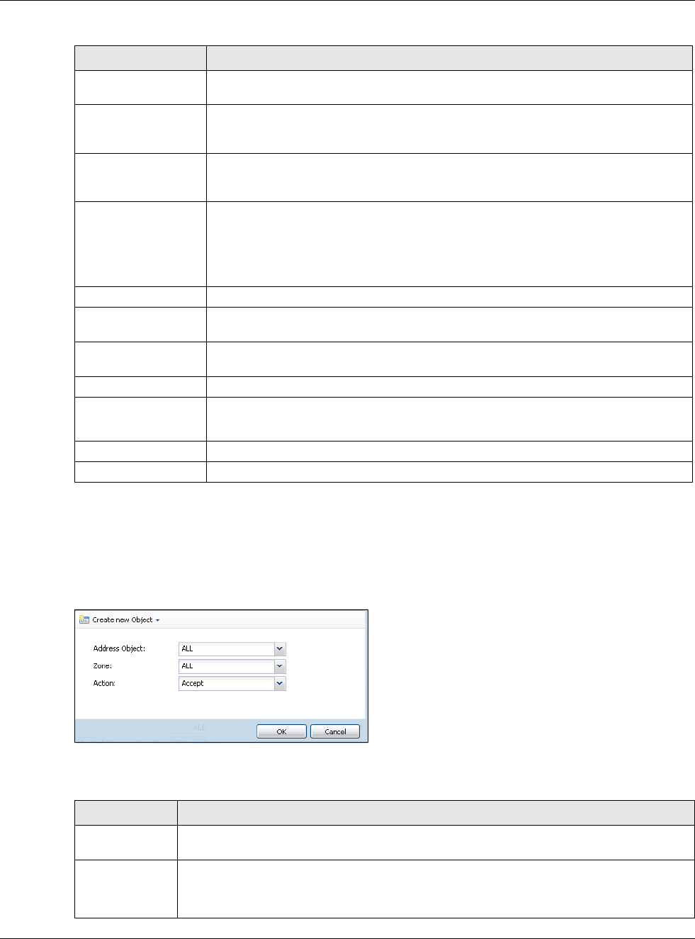
Figure 381 Configuration > System > Service Control Rule > Edit
The following table describes the labels in this screen.
Edit Double-click an entry or select it and click Edit to be able to modify the entry’s
settings.
Remove To remove an entry, select it and click Remove. The USG confirms you want to
remove it before doing so. Note that subsequent entries move up by one when you
take this action.
Move To change an entry’s position in the numbered list, select the method and click Move
to display a field to type a number for where you want to put it and press [ENTER] to
move the rule to the number that you typed.
#This is the index number of the service control rule.
The entry with a hyphen (-) instead of a number is the USG’s (non-configurable)
default policy. The USG applies this to traffic that does not match any other
configured rule. It is not an editable rule. To apply other behavior, configure a rule
that traffic will match so the USG will not have to use the default policy.
Zone This is the zone on the USG the user is allowed or denied to access.
Address This is the object name of the IP address(es) with which the computer is allowed or
denied to access.
Action This displays whether the computer with the IP address specified above can access
the USG zone(s) configured in the Zone field (Accept) or not (Deny).
Authentication
Client Authentication
Method
Select a method the HTTPS or HTTP server uses to authenticate a client.
You must have configured the authentication methods in the Auth. method screen.
Apply Click Apply to save your changes back to the USG.
Reset Click Reset to return the screen to its last-saved settings.
Table 241 Configuration > System > WWW > Service Control (continued)
LABEL DESCRIPTION
Table 242 Configuration > System > Service Control Rule > Edit
LABEL DESCRIPTION
Create new
Object
Use this to configure any new settings objects that you need to use in this screen.
Address Object Select ALL to allow or deny any computer to communicate with the USG using this service.
Select a predefined address object to just allow or deny the computer with the IP address
that you specified to access the USG using this service.
Chapter 30 System
USG20(W)-VPN Series User’s Guide
559
30.7.6 Customizing the WWW Login Page
Click Configuration > System > WWW > Login Page to open the Login Page screen. Use this
screen to customize the Web Configurator login screen. You can also customize the page that
displays after an access user logs into the Web Configurator to access network services like the
Internet.
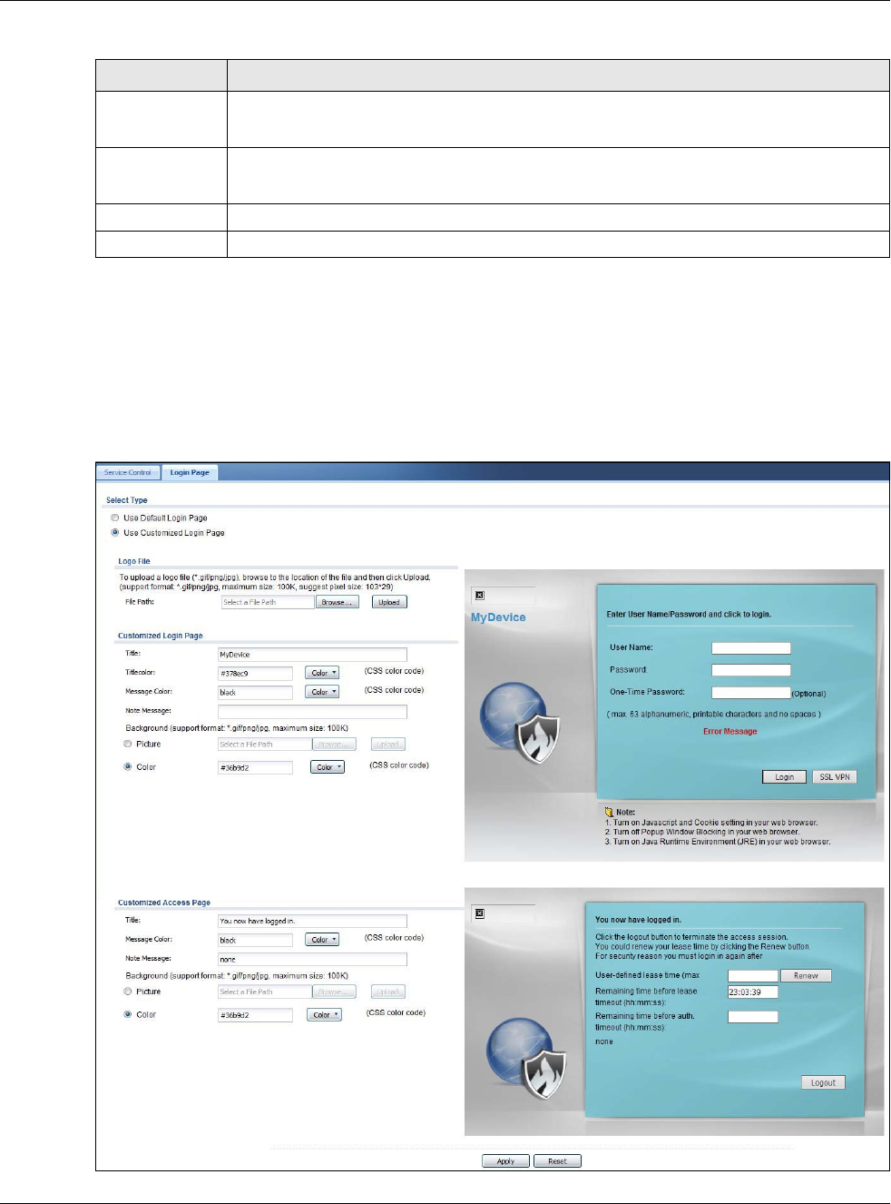
Figure 382 Configuration > System > WWW > Login Page
Zone Select ALL to allow or prevent any USG zones from being accessed using this service.
Select a predefined USG zone on which a incoming service is allowed or denied.
Action Select Accept to allow the user to access the USG from the specified computers.
Select Deny to block the user’s access to the USG from the specified computers.
OK Click OK to save your customized settings and exit this screen.
Cancel Click Cancel to exit this screen without saving
Table 242 Configuration > System > Service Control Rule > Edit
LABEL DESCRIPTION
Chapter 30 System
USG20(W)-VPN Series User’s Guide
560
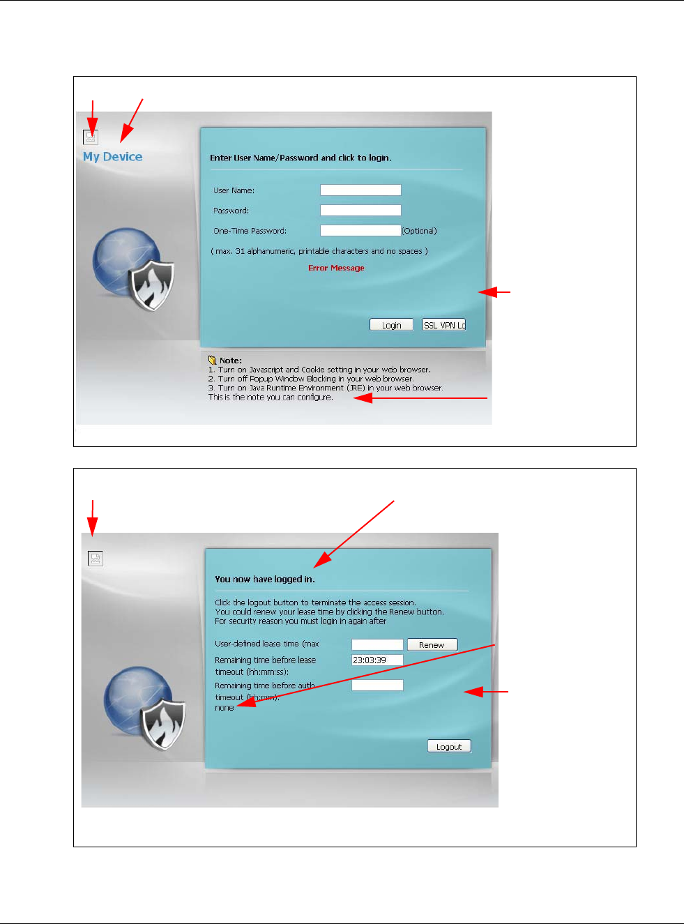
The following figures identify the parts you can customize in the login and access pages.
Figure 383 Login Page Customization
Figure 384 Access Page Customization
You can specify colors in one of the following ways:
• Click Color to display a screen of web-safe colors from which to choose.
Logo Title
Message
Note Message
Background
(last line of text)
(color of all text)
Logo Title
Message
Note Message
Window
(last line of text)
(color of all text)
Background
Chapter 30 System
USG20(W)-VPN Series User’s Guide
561
• Enter the name of the desired color.
• Enter a pound sign (#) followed by the six-digit hexadecimal number that represents the desired
color. For example, use “#000000” for black.
• Enter “rgb” followed by red, green, and blue values in parenthesis and separate by commas. For
example, use “rgb(0,0,0)” for black.
Your desired color should display in the preview screen on the right after you click in another field,
click Apply, or press [ENTER]. If your desired color does not display, your browser may not support
it. Try selecting another color.
The following table describes the labels in the screen.
Table 243 Configuration > System > WWW > Login Page
LABEL DESCRIPTION
Select Type Select whether the Web Configurator uses the default login screen or one that you
customize in the rest of this screen.
Logo File You can upload a graphic logo to be displayed on the upper left corner of the Web
Configurator login screen and access page.
Specify the location and file name of the logo graphic or click Browse to locate it.
Note: Use a GIF, JPG, or PNG of 100 kilobytes or less.
Click Upload to transfer the specified graphic file from your computer to the USG.
Customized
Login Page
Use this section to set how the Web Configurator login screen looks.
Title Enter the title for the top of the screen. Use up to 64 printable ASCII characters. Spaces
are allowed.
Title Color Specify the color of the screen’s title text.
Message Color Specify the color of the screen’s text.
Note Message Enter a note to display at the bottom of the screen. Use up to 64 printable ASCII
characters. Spaces are allowed.
Background Set how the screen background looks.
To use a graphic, select Picture and upload a graphic. Specify the location and file name of
the logo graphic or click Browse to locate it. The picture’s size cannot be over 438 x 337
pixels.
Note: Use a GIF, JPG, or PNG of 100 kilobytes or less.
To use a color, select Color and specify the color.
Customized
Access Page
Use this section to customize the page that displays after an access user logs into the Web
Configurator to access network services like the Internet.
Title Enter the title for the top of the screen. Use up to 64 printable ASCII characters. Spaces
are allowed.
Message Color Specify the color of the screen’s text.
Note Message Enter a note to display below the title. Use up to 64 printable ASCII characters. Spaces are
allowed.
Chapter 30 System
USG20(W)-VPN Series User’s Guide
562
30.7.7 HTTPS Example
If you haven’t changed the default HTTPS port on the USG, then in your browser enter “https://
USG IP Address/” as the web site address where “USG IP Address” is the IP address or domain
name of the USG you wish to access.
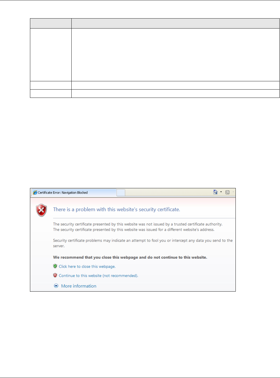
30.7.7.1 Internet Explorer Warning Messages
When you attempt to access the USG HTTPS server, you will see the error message shown in the
following screen.
Figure 385 Security Alert Dialog Box (Internet Explorer)
Select Continue to this website to proceed to the Web Configurator login screen. Otherwise,
select Click here to close this webpage to block the access.
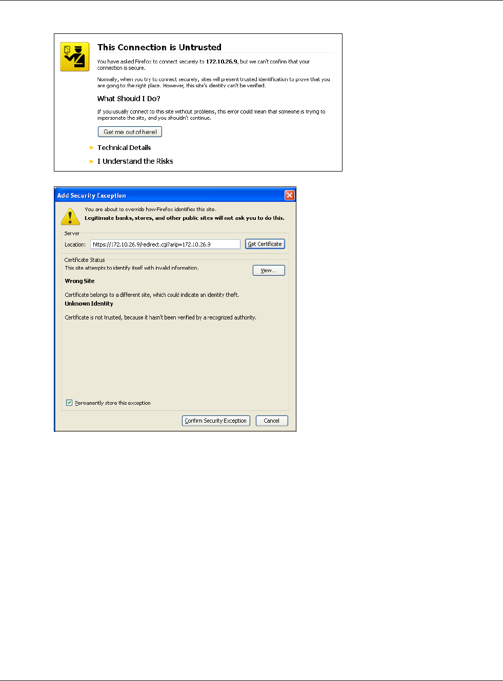
30.7.7.2 Mozilla Firefox Warning Messages
When you attempt to access the USG HTTPS server, a The Connection is Untrusted screen
appears as shown in the following screen. Click Technical Details if you want to verify more
information about the certificate from the USG.
Select I Understand the Risks and then click Add Exception to add the USG to the security
exception list. Click Confirm Security Exception.
Background Set how the window’s background looks.
To use a graphic, select Picture and upload a graphic. Specify the location and file name of
the logo graphic or click Browse to locate it. The picture’s size cannot be over 438 x 337
pixels.
Note: Use a GIF, JPG, or PNG of 100 kilobytes or less.
To use a color, select Color and specify the color.
Apply Click Apply to save your changes back to the USG.
Reset Click Reset to return the screen to its last-saved settings.
Table 243 Configuration > System > WWW > Login Page
LABEL DESCRIPTION
Chapter 30 System
USG20(W)-VPN Series User’s Guide
563
Figure 386 Security Certificate 1 (Firefox)
Figure 387 Security Certificate 2 (Firefox)
30.7.7.3 Avoiding Browser Warning Messages
Here are the main reasons your browser displays warnings about the USG’s HTTPS server certificate
and what you can do to avoid seeing the warnings:
• The issuing certificate authority of the USG’s HTTPS server certificate is not one of the browser’s
trusted certificate authorities. The issuing certificate authority of the USG's factory default
certificate is the USG itself since the certificate is a self-signed certificate.
• For the browser to trust a self-signed certificate, import the self-signed certificate into your
operating system as a trusted certificate.
• To have the browser trust the certificates issued by a certificate authority, import the certificate
authority’s certificate into your operating system as a trusted certificate.
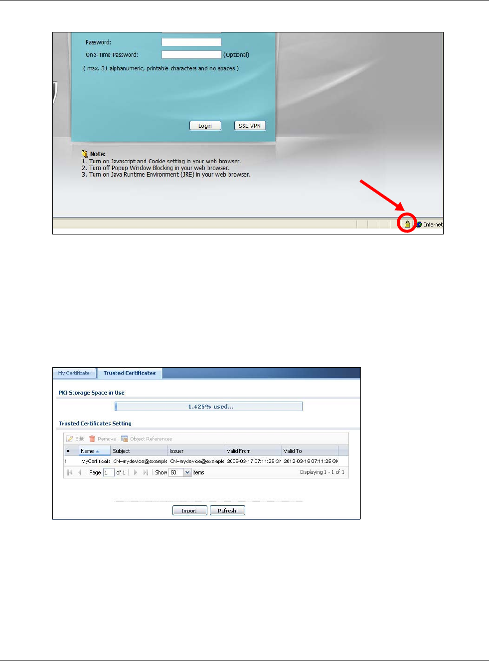
30.7.7.4 Login Screen
After you accept the certificate, the USG login screen appears. The lock displayed in the bottom of
the browser status bar denotes a secure connection.
Chapter 30 System
USG20(W)-VPN Series User’s Guide
564
Figure 388 Login Screen (Internet Explorer)
30.7.7.5 Enrolling and Importing SSL Client Certificates
The SSL client needs a certificate if Authenticate Client Certificates is selected on the USG.
You must have imported at least one trusted CA to the USG in order for the Authenticate Client
Certificates to be active (see the Certificates chapter for details).
Apply for a certificate from a Certification Authority (CA) that is trusted by the USG (see the USG’s
Trusted CA Web Configurator screen).
Figure 389 USG Trusted CA Screen
The CA sends you a package containing the CA’s trusted certificate(s), your personal certificate(s)
and a password to install the personal certificate(s).
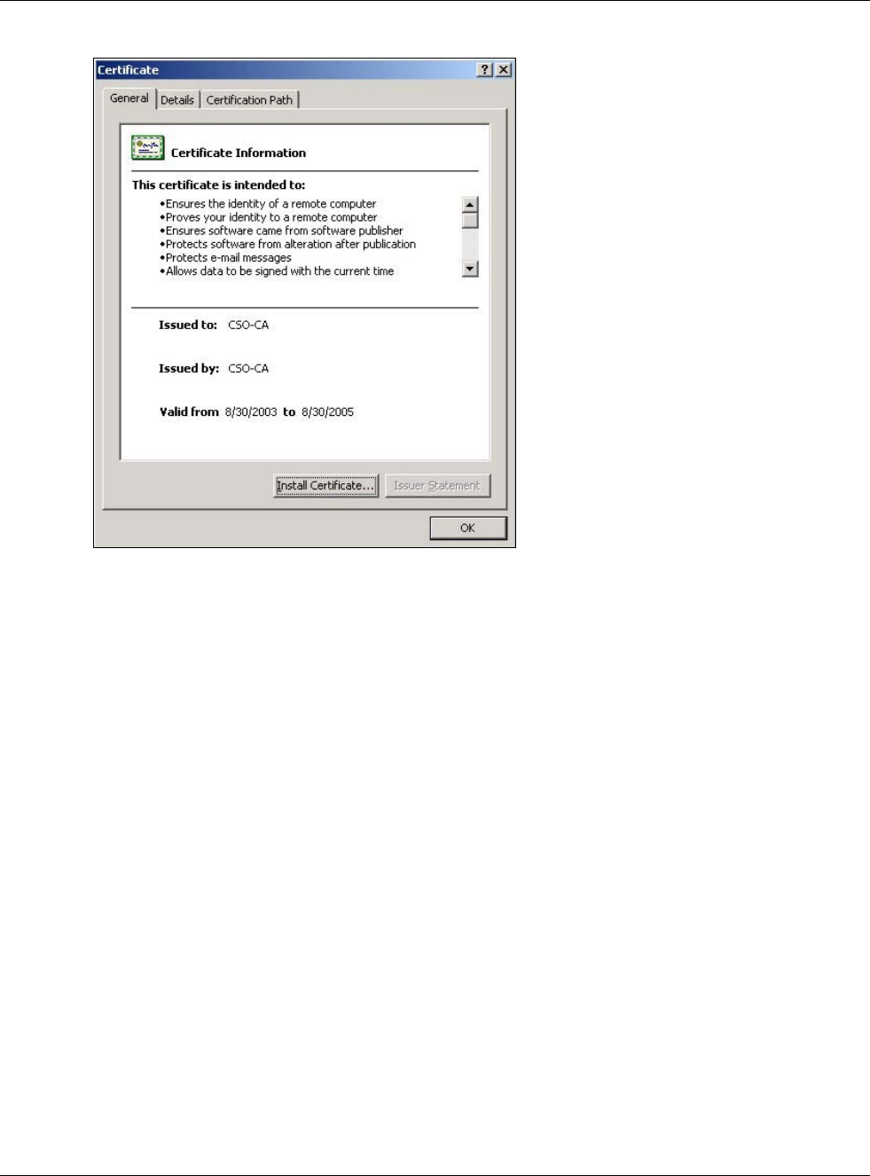
30.7.7.5.1 Installing the CA’s Certificate
1Double click the CA’s trusted certificate to produce a screen similar to the one shown next.
Chapter 30 System
USG20(W)-VPN Series User’s Guide
565
Figure 390 CA Certificate Example
2Click Install Certificate and follow the wizard as shown earlier in this appendix.
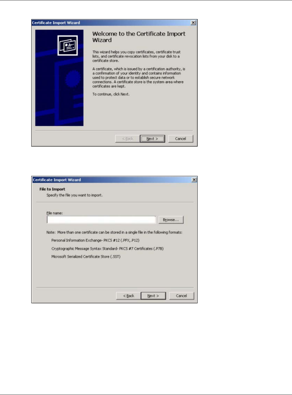
30.7.7.5.2 Installing Your Personal Certificate(s)
You need a password in advance. The CA may issue the password or you may have to specify it
during the enrollment. Double-click the personal certificate given to you by the CA to produce a
screen similar to the one shown next
1Click Next to begin the wizard.
Chapter 30 System
USG20(W)-VPN Series User’s Guide
566
Figure 391 Personal Certificate Import Wizard 1
2The file name and path of the certificate you double-clicked should automatically appear in the File
name text box. Click Browse if you wish to import a different certificate.
Figure 392 Personal Certificate Import Wizard 2
3Enter the password given to you by the CA.

Chapter 30 System
USG20(W)-VPN Series User’s Guide
567
Figure 393 Personal Certificate Import Wizard 3
4Have the wizard determine where the certificate should be saved on your computer or select Place
all certificates in the following store and choose a different location.
Figure 394 Personal Certificate Import Wizard 4
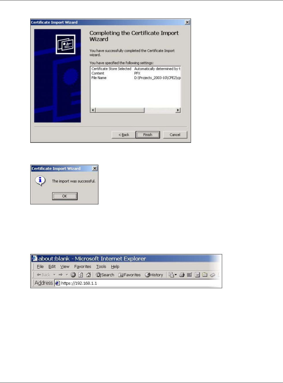
5Click Finish to complete the wizard and begin the import process.
Chapter 30 System
USG20(W)-VPN Series User’s Guide
568
Figure 395 Personal Certificate Import Wizard 5
6You should see the following screen when the certificate is correctly installed on your computer.
Figure 396 Personal Certificate Import Wizard 6
30.7.7.6 Using a Certificate When Accessing the USG Example
Use the following procedure to access the USG via HTTPS.
1Enter ‘https://USG IP Address/ in your browser’s web address field.
Figure 397 Access the USG Via HTTPS
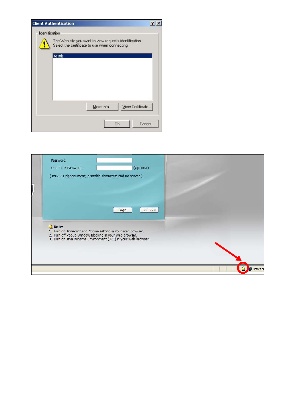
2When Authenticate Client Certificates is selected on the USG, the following screen asks you to
select a personal certificate to send to the USG. This screen displays even if you only have a single
certificate as in the example.
Chapter 30 System
USG20(W)-VPN Series User’s Guide
569
Figure 398 SSL Client Authentication
3You next see the Web Configurator login screen.
Figure 399 Secure Web Configurator Login Screen
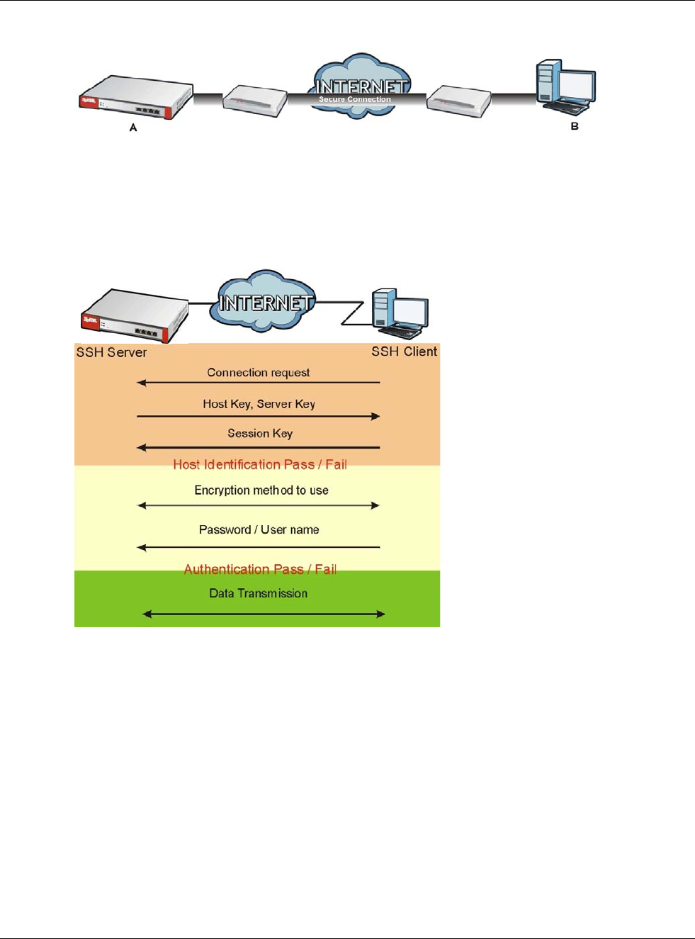
30.8 SSH
You can use SSH (Secure SHell) to securely access the USG’s command line interface. Specify
which zones allow SSH access and from which IP address the access can come.
SSH is a secure communication protocol that combines authentication and data encryption to
provide secure encrypted communication between two hosts over an unsecured network. In the
following figure, computer A on the Internet uses SSH to securely connect to the WAN port of the
USG for a management session.
Chapter 30 System
USG20(W)-VPN Series User’s Guide
570
Figure 400 SSH Communication Over the WAN Example
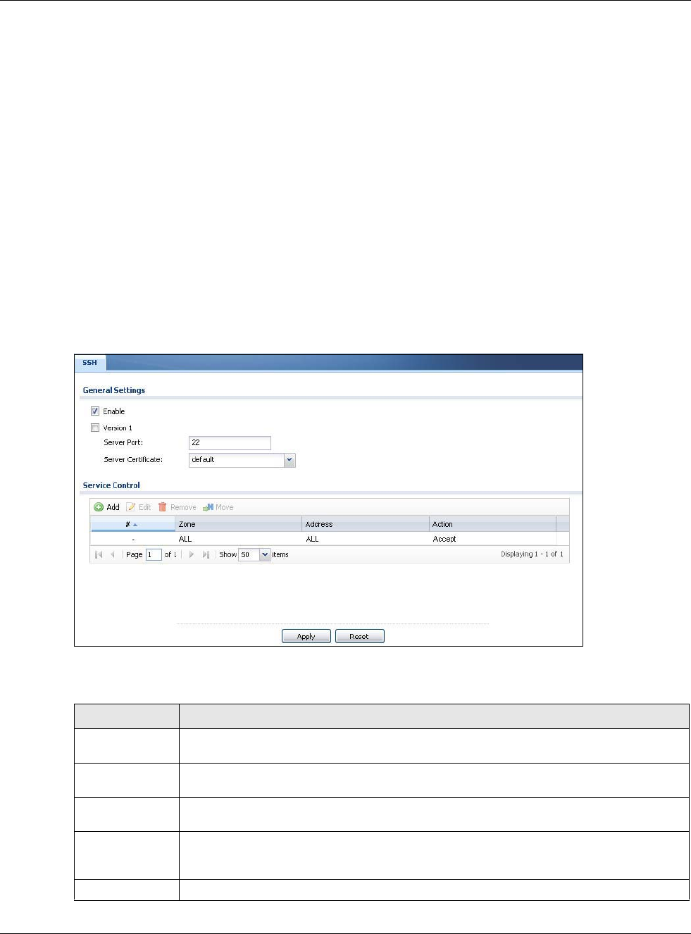
30.8.1 How SSH Works
The following figure is an example of how a secure connection is established between two remote
hosts using SSH v1.
Figure 401 How SSH v1 Works Example
1Host Identification
The SSH client sends a connection request to the SSH server. The server identifies itself with a host
key. The client encrypts a randomly generated session key with the host key and server key and
sends the result back to the server.
The client automatically saves any new server public keys. In subsequent connections, the server
public key is checked against the saved version on the client computer.
2Encryption Method
Once the identification is verified, both the client and server must agree on the type of encryption
method to use.
3Authentication and Data Transmission
After the identification is verified and data encryption activated, a secure tunnel is established
between the client and the server. The client then sends its authentication information (user name
and password) to the server to log in to the server.
Chapter 30 System
USG20(W)-VPN Series User’s Guide
571
30.8.2 SSH Implementation on the USG
Your USG supports SSH versions 1 and 2 using RSA authentication and four encryption methods
(AES, 3DES, Archfour, and Blowfish). The SSH server is implemented on the USG for management
using port 22 (by default).
30.8.3 Requirements for Using SSH
You must install an SSH client program on a client computer (Windows or Linux operating system)
that is used to connect to the USG over SSH.
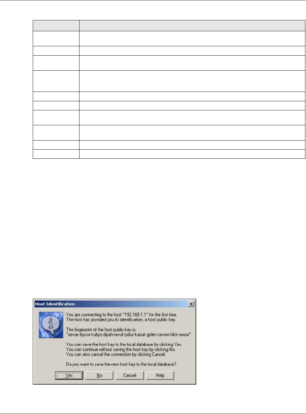
30.8.4 Configuring SSH
Click Configuration > System > SSH to change your USG’s Secure Shell settings. Use this screen
to specify from which zones SSH can be used to manage the USG. You can also specify from which
IP addresses the access can come.
Figure 402 Configuration > System > SSH
The following table describes the labels in this screen.
Table 244 Configuration > System > SSH
LABEL DESCRIPTION
Enable Select the check box to allow or disallow the computer with the IP address that matches
the IP address(es) in the Service Control table to access the USG CLI using this service.
Version 1 Select the check box to have the USG use both SSH version 1 and version 2 protocols. If
you clear the check box, the USG uses only SSH version 2 protocol.
Server Port You may change the server port number for a service if needed, however you must use the
same port number in order to use that service for remote management.
Server
Certificate
Select the certificate whose corresponding private key is to be used to identify the USG for
SSH connections. You must have certificates already configured in the My Certificates
screen.
Service Control This specifies from which computers you can access which USG zones.
Chapter 30 System
USG20(W)-VPN Series User’s Guide
572
30.8.5 Secure Telnet Using SSH Examples
This section shows two examples using a command interface and a graphical interface SSH client
program to remotely access the USG. The configuration and connection steps are similar for most
SSH client programs. Refer to your SSH client program user’s guide.
30.8.5.1 Example 1: Microsoft Windows
This section describes how to access the USG using the Secure Shell Client program.
1Launch the SSH client and specify the connection information (IP address, port number) for the
USG.
2Configure the SSH client to accept connection using SSH version 1.
3A window displays prompting you to store the host key in you computer. Click Yes to continue.
Figure 403 SSH Example 1: Store Host Key
Enter the password to log in to the USG. The CLI screen displays next.
Add Click this to create a new entry. Select an entry and click Add to create a new entry after
the selected entry. Refer to Table 242 on page 558 for details on the screen that opens.
Edit Double-click an entry or select it and click Edit to be able to modify the entry’s settings.
Remove To remove an entry, select it and click Remove. The USG confirms you want to remove it
before doing so. Note that subsequent entries move up by one when you take this action.
Move To change an entry’s position in the numbered list, select the method and click Move to
display a field to type a number for where you want to put it and press [ENTER] to move
the rule to the number that you typed.
#This the index number of the service control rule.
Zone This is the zone on the USG the user is allowed or denied to access.
Address This is the object name of the IP address(es) with which the computer is allowed or denied
to access.
Action This displays whether the computer with the IP address specified above can access the
USG zone(s) configured in the Zone field (Accept) or not (Deny).
Apply Click Apply to save your changes back to the USG.
Reset Click Reset to return the screen to its last-saved settings.
Table 244 Configuration > System > SSH (continued)
LABEL DESCRIPTION
Chapter 30 System
USG20(W)-VPN Series User’s Guide
573
30.8.5.2 Example 2: Linux
This section describes how to access the USG using the OpenSSH client program that comes with
most Linux distributions.
1Test whether the SSH service is available on the USG.
Enter “telnet 192.168.1.1 22” at a terminal prompt and press [ENTER]. The computer
attempts to connect to port 22 on the USG (using the default IP address of 192.168.1.1).
A message displays indicating the SSH protocol version supported by the USG.
Figure 404 SSH Example 2: Test
2Enter “ssh –1 192.168.1.1”. This command forces your computer to connect to the USG using
SSH version 1. If this is the first time you are connecting to the USG using SSH, a message displays
prompting you to save the host information of the USG. Type “yes” and press [ENTER].
Then enter the password to log in to the USG.
Figure 405 SSH Example 2: Log in
3The CLI screen displays next.
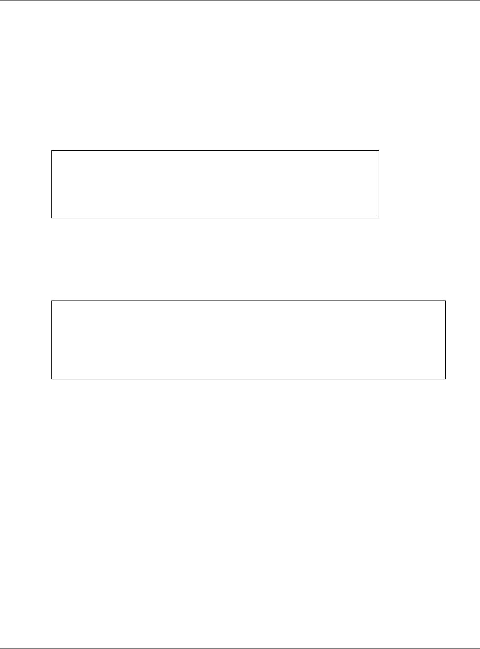
30.9 Telnet
You can use Telnet to access the USG’s command line interface. Specify which zones allow Telnet
access and from which IP address the access can come.
30.9.1 Configuring Telnet
Click Configuration > System > TELNET to configure your USG for remote Telnet access. Use
this screen to specify from which zones Telnet can be used to manage the USG. You can also specify
from which IP addresses the access can come.
$ telnet 192.168.1.1 22
Trying 192.168.1.1...
Connected to 192.168.1.1.
Escape character is '^]'.
SSH-1.5-1.0.0
$ ssh –1 192.168.1.1
The authenticity of host '192.168.1.1 (192.168.1.1)' can't be established.
RSA1 key fingerprint is 21:6c:07:25:7e:f4:75:80:ec:af:bd:d4:3d:80:53:d1.
Are you sure you want to continue connecting (yes/no)? yes
Warning: Permanently added '192.168.1.1' (RSA1) to the list of known hosts.
Administrator@192.168.1.1's password:
Chapter 30 System
USG20(W)-VPN Series User’s Guide
574
Figure 406 Configuration > System > TELNET
The following table describes the labels in this screen.
Table 245 Configuration > System > TELNET
LABEL DESCRIPTION
Enable Select the check box to allow or disallow the computer with the IP address that matches
the IP address(es) in the Service Control table to access the USG CLI using this service.
Server Port You may change the server port number for a service if needed, however you must use the
same port number in order to use that service for remote management.
Service Control This specifies from which computers you can access which USG zones.
Add Click this to create a new entry. Select an entry and click Add to create a new entry after
the selected entry. Refer to Table 242 on page 558 for details on the screen that opens.
Edit Double-click an entry or select it and click Edit to be able to modify the entry’s settings.
Remove To remove an entry, select it and click Remove. The USG confirms you want to remove it
before doing so. Note that subsequent entries move up by one when you take this action.
Move To change an entry’s position in the numbered list, select the method and click Move to
display a field to type a number for where you want to put it and press [ENTER] to move
the rule to the number that you typed.
#This the index number of the service control rule.
The entry with a hyphen (-) instead of a number is the USG’s (non-configurable) default
policy. The USG applies this to traffic that does not match any other configured rule. It is
not an editable rule. To apply other behavior, configure a rule that traffic will match so the
USG will not have to use the default policy.
Zone This is the zone on the USG the user is allowed or denied to access.
Address This is the object name of the IP address(es) with which the computer is allowed or denied
to access.
Action This displays whether the computer with the IP address specified above can access the
USG zone(s) configured in the Zone field (Accept) or not (Deny).
Apply Click Apply to save your changes back to the USG.
Reset Click Reset to return the screen to its last-saved settings.
Chapter 30 System
USG20(W)-VPN Series User’s Guide
575
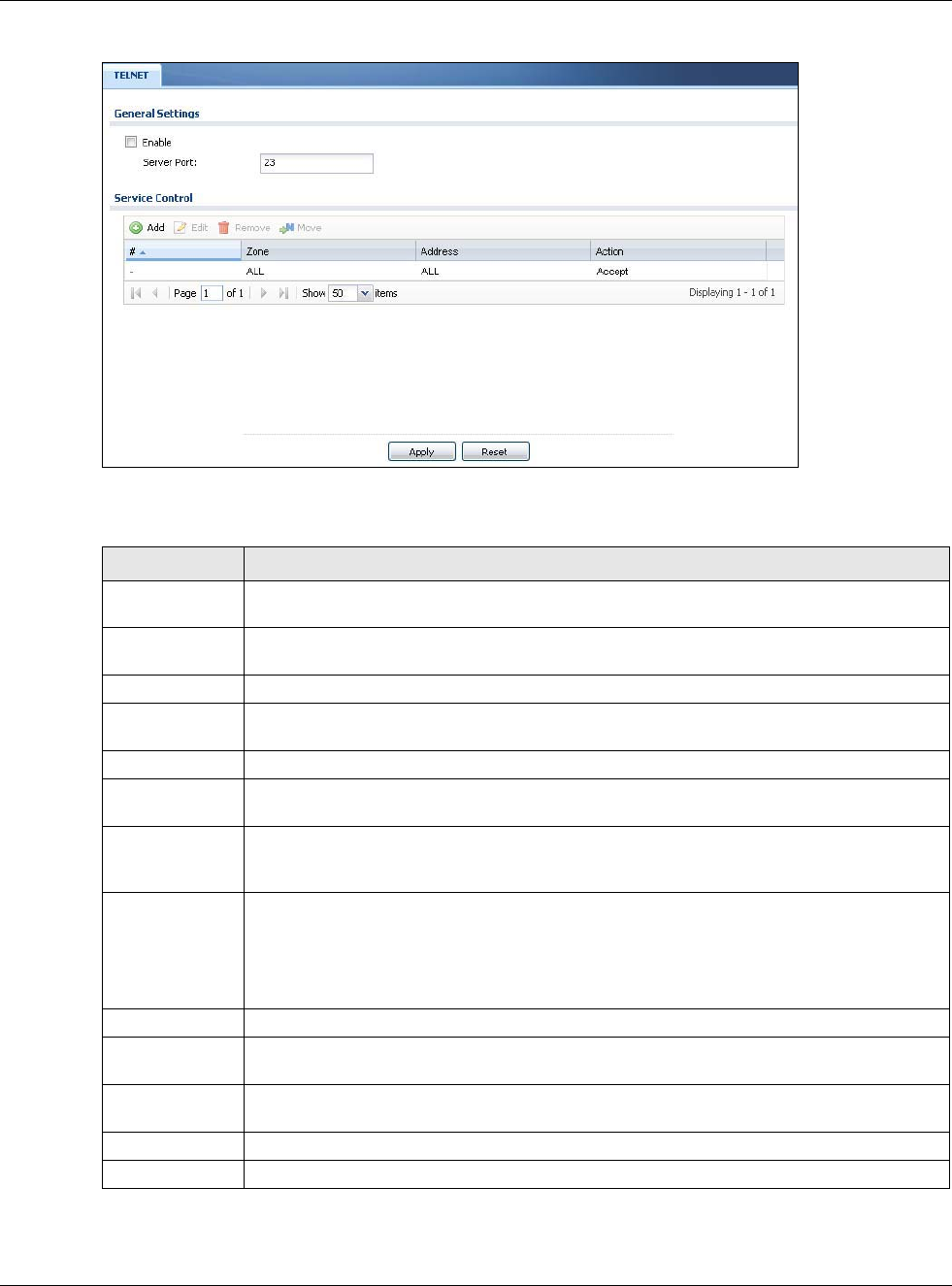
30.10 FTP
You can upload and download the USG’s firmware and configuration files using FTP. To use this
feature, your computer must have an FTP client.
30.10.1 Configuring FTP
To change your USG’s FTP settings, click Configuration > System > FTP tab. The screen appears
as shown. Use this screen to specify from which zones FTP can be used to access the USG. You can
also specify from which IP addresses the access can come.
Figure 407 Configuration > System > FTP
The following table describes the labels in this screen.
Table 246 Configuration > System > FTP
LABEL DESCRIPTION
Enable Select the check box to allow or disallow the computer with the IP address that matches
the IP address(es) in the Service Control table to access the USG using this service.
TLS required Select the check box to use FTP over TLS (Transport Layer Security) to encrypt
communication.
This implements TLS as a security mechanism to secure FTP clients and/or servers.
Server Port You may change the server port number for a service if needed, however you must use the
same port number in order to use that service for remote management.
Server
Certificate
Select the certificate whose corresponding private key is to be used to identify the USG for
FTP connections. You must have certificates already configured in the My Certificates
screen.
Service Control This specifies from which computers you can access which USG zones.
Add Click this to create a new entry. Select an entry and click Add to create a new entry after
the selected entry. Refer to Table 242 on page 558 for details on the screen that opens.
Edit Double-click an entry or select it and click Edit to be able to modify the entry’s settings.
Remove To remove an entry, select it and click Remove. The USG confirms you want to remove it
before doing so. Note that subsequent entries move up by one when you take this action.
Chapter 30 System
USG20(W)-VPN Series User’s Guide
576
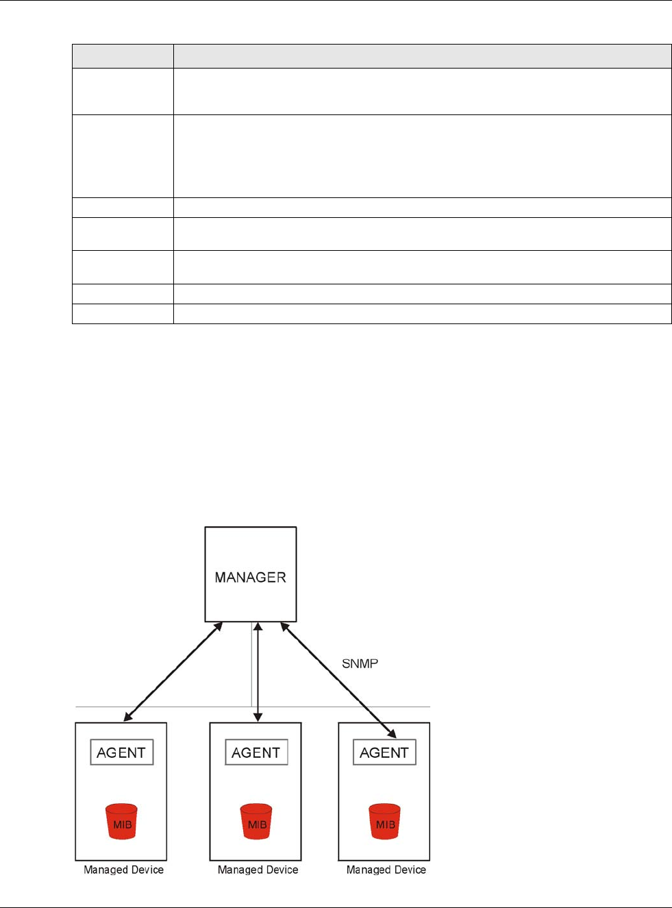
30.11 SNMP
Simple Network Management Protocol is a protocol used for exchanging management information
between network devices. Your USG supports SNMP agent functionality, which allows a manager
station to manage and monitor the USG through the network. The USG supports SNMP version one
(SNMPv1), version two (SNMPv2c) and version 3 (SNMPv3). The next figure illustrates an SNMP
management operation.
Figure 408 SNMP Management Model
Move To change an entry’s position in the numbered list, select the method and click Move to
display a field to type a number for where you want to put it and press [ENTER] to move
the rule to the number that you typed.
#This the index number of the service control rule.
The entry with a hyphen (-) instead of a number is the USG’s (non-configurable) default
policy. The USG applies this to traffic that does not match any other configured rule. It is
not an editable rule. To apply other behavior, configure a rule that traffic will match so the
USG will not have to use the default policy.
Zone This is the zone on the USG the user is allowed or denied to access.
Address This is the object name of the IP address(es) with which the computer is allowed or denied
to access.
Action This displays whether the computer with the IP address specified above can access the
USG zone(s) configured in the Zone field (Accept) or not (Deny).
Apply Click Apply to save your changes back to the USG.
Reset Click Reset to return the screen to its last-saved settings.
Table 246 Configuration > System > FTP (continued)
LABEL DESCRIPTION
Chapter 30 System
USG20(W)-VPN Series User’s Guide
577
An SNMP managed network consists of two main types of component: agents and a manager.
An agent is a management software module that resides in a managed device (the USG). An agent
translates the local management information from the managed device into a form compatible with
SNMP. The manager is the console through which network administrators perform network
management functions. It executes applications that control and monitor managed devices.
The managed devices contain object variables/managed objects that define each piece of
information to be collected about a device. Examples of variables include such as number of
packets received, node port status etc. A Management Information Base (MIB) is a collection of
managed objects. SNMP allows a manager and agents to communicate for the purpose of accessing
these objects.
SNMP itself is a simple request/response protocol based on the manager/agent model. The
manager issues a request and the agent returns responses using the following protocol operations:
• Get - Allows the manager to retrieve an object variable from the agent.
• GetNext - Allows the manager to retrieve the next object variable from a table or list within an
agent. In SNMPv1, when a manager wants to retrieve all elements of a table from an agent, it
initiates a Get operation, followed by a series of GetNext operations.
• Set - Allows the manager to set values for object variables within an agent.
• Trap - Used by the agent to inform the manager of some events.
30.11.1 SNMPv3 and Security
SNMPv3 enhances security for SNMP management using authentication and encryption. SNMP
managers can be required to authenticate with agents before conducting SNMP management
sessions.
Security can be further enhanced by encrypting the SNMP messages sent from the managers.
Encryption protects the contents of the SNMP messages. When the contents of the SNMP messages
are encrypted, only the intended recipients can read them.
30.11.2 Supported MIBs
The USG supports MIB II that is defined in RFC-1213 and RFC-1215. The USG also supports private
MIBs (zywall.mib and zyxel-zywall-ZLD-Common.mib) to collect information about CPU and
memory usage and VPN total throughput. The focus of the MIBs is to let administrators collect
statistical data and monitor status and performance. You can download the USG’s MIBs from
www.zyxel.com.
30.11.3 SNMP Traps
The USG will send traps to the SNMP manager when any one of the following events occurs.
Table 247 SNMP Traps
OBJECT LABEL OBJECT ID DESCRIPTION
Cold Start 1.3.6.1.6.3.1.1.5.1 This trap is sent when the USG is turned on or an
agent restarts.
linkDown 1.3.6.1.6.3.1.1.5.3 This trap is sent when the Ethernet link is down.
Chapter 30 System
USG20(W)-VPN Series User’s Guide
578
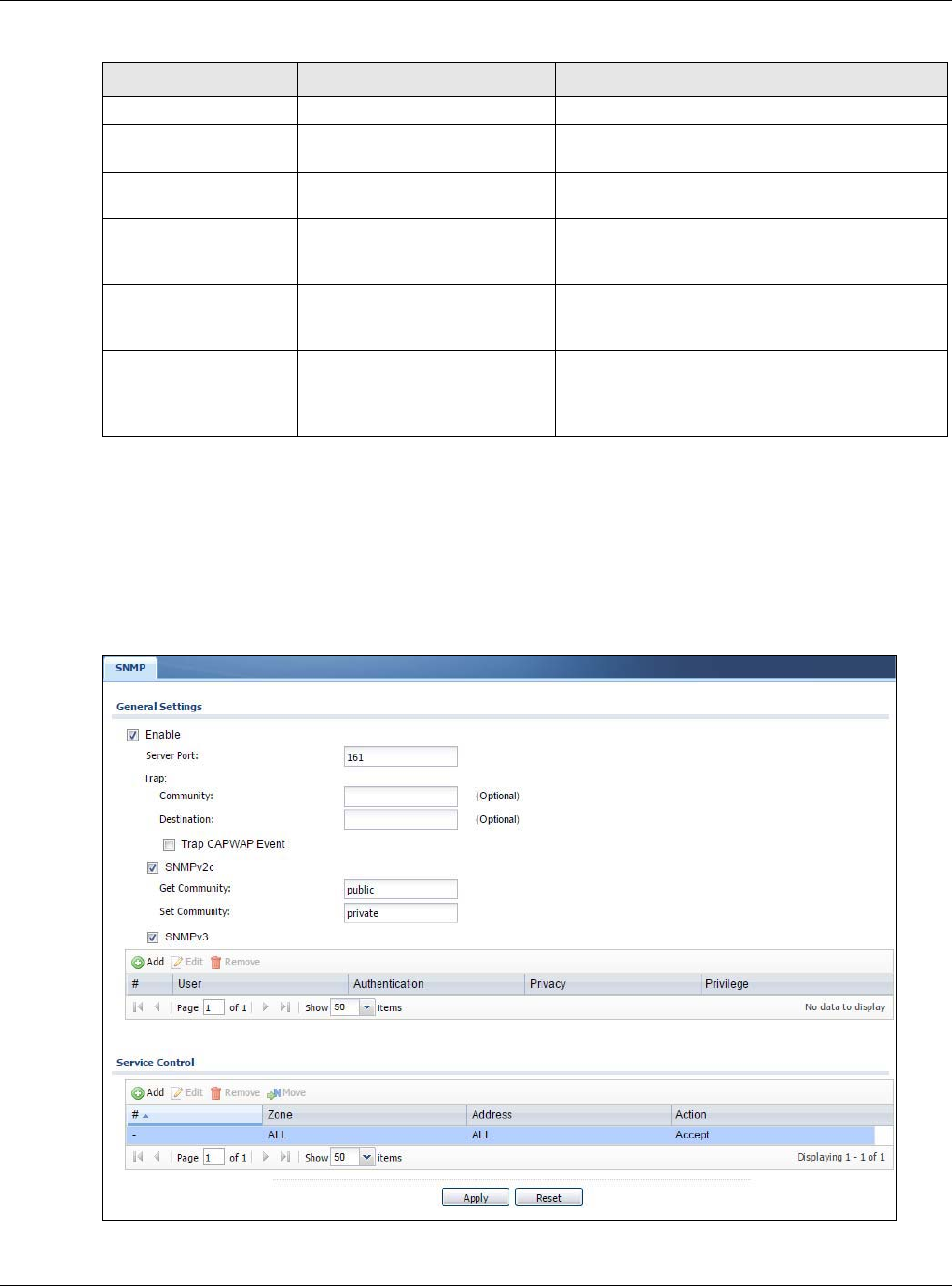
30.11.4 Configuring SNMP
To change your USG’s SNMP settings, click Configuration > System > SNMP tab. The screen
appears as shown. Use this screen to configure your SNMP settings, including from which zones
SNMP can be used to access the USG. You can also specify from which IP addresses the access can
come.
Figure 409 Configuration > System > SNMP
linkUp 1.3.6.1.6.3.1.1.5.4 This trap is sent when the Ethernet link is up.
authenticationFailure 1.3.6.1.6.3.1.1.5.5 This trap is sent when an SNMP request comes
from non-authenticated hosts.
vpnTunnelDisconnected 1.3.6.1.4.1.890.1.6.22.2.3 This trap is sent when an IPSec VPN tunnel is
disconnected.
vpnTunnelName 1.3.6.1.4.1.890.1.6.22.2.2.1.1 This trap is sent along with the
vpnTunnelDisconnected trap. This trap carries the
disconnected tunnel’s IPSec SA name.
vpnIKEName 1.3.6.1.4.1.890.1.6.22.2.2.1.2 This trap is sent along with the
vpnTunnelDisconnected trap. This trap carries the
disconnected tunnel’s IKE SA name.
vpnTunnelSPI 1.3.6.1.4.1.890.1.6.22.2.2.1.3 This trap is sent along with the
vpnTunnelDisconnected trap. This trap carries the
security parameter index (SPI) of the
disconnected VPN tunnel.
Table 247 SNMP Traps (continued)
OBJECT LABEL OBJECT ID DESCRIPTION
Chapter 30 System
USG20(W)-VPN Series User’s Guide
579
The following table describes the labels in this screen.
Table 248 Configuration > System > SNMP
LABEL DESCRIPTION
Enable Select the check box to allow or disallow the computer with the IP address that matches
the IP address(es) in the Service Control table to access the USG using this service.
Server Port You may change the server port number for a service if needed, however you must use the
same port number in order to use that service for remote management.
Trap
Community Type the trap community, which is the password sent with each trap to the SNMP manager.
The default is public and allows all requests.
Destination Type the IP address of the station to send your SNMP traps to.
SNMPv2c Select the SNMP version for the USG. The SNMP version on the USG must match the
version on the SNMP manager.
Get
Community Enter the Get Community, which is the password for the incoming Get and GetNext
requests from the management station. The default is public and allows all requests.
Set
Community Enter the Set community, which is the password for incoming Set requests from the
management station. The default is private and allows all requests.
SNMPv3 Select the SNMP version for the USG. The SNMP version on the USG must match the
version on the SNMP manager. SNMPv3 (RFCs 3413 to 3415) provides secure access by
authenticating and encrypting data packets over the network. The USG uses your login
password as the SNMPv3 authentication and encryption passphrase.
Note: Your login password must consist of at least 8 printable characters for SNMPv3. An
error message will display if your login password has fewer characters.
Add Click this to create a new entry. Select an entry and click Add to create a new entry after
the selected entry
Edit Double-click an entry or select it and click Edit to be able to modify the entry’s settings.
Remove To remove an entry, select it and click Remove. The USG confirms you want to remove it
before doing so. Note that subsequent entries move up by one when you take this action.
#This is the index number of the entry.
User This displays the name of the user object to be sent to the SNMP manager along with the
SNMP v3 trap.
Authenticati
on This displays the authentication algorithm used for this entry. MD5 (Message Digest 5) and
SHA (Secure Hash Algorithm) are hash algorithms used to authenticate SNMP data. SHA
authentication is generally considered stronger than MD5, but is slower.
Privacy This displays the encryption method for SNMP communication from this user. Methods
available are:
•DES - Data Encryption Standard is a widely used (but breakable) method of data
encryption. It applies a 56-bit key to each 64-bit block of data.
•AES - Advanced Encryption Standard is another method for data encryption that also
uses a secret key. AES applies a 128-bit key to 128-bit blocks of data.
Privlege This displays the access rights to MIBs.
•Read-Write - The associated user can create and edit the MIBs on the USG, except the
user account.
•Read-Only - The associated user can only collect information from the USG MIBs.
Service Control This specifies from which computers you can access which USG zones.
Add Click this to create a new entry. Select an entry and click Add to create a new entry after
the selected entry. Refer to Table 242 on page 558 for details on the screen that opens.
Edit Double-click an entry or select it and click Edit to be able to modify the entry’s settings.
Remove To remove an entry, select it and click Remove. The USG confirms you want to remove it
before doing so. Note that subsequent entries move up by one when you take this action.
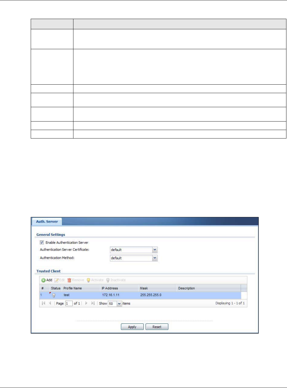
Chapter 30 System
USG20(W)-VPN Series User’s Guide
580
30.12 Authentication Server
You can set the USG to work as a RADIUS server to exchange messages with a RADIUS client, such
as an AP for user authentication and authorization. Click Configuration > System > Auth.
Server tab. The screen appears as shown. Use this screen to enable the authentication server
feature of the USG and specify the RADIUS client’s IP address.
Figure 410 Configuration > System > Auth. Server
Move To change an entry’s position in the numbered list, select the method and click Move to
display a field to type a number for where you want to put it and press [ENTER] to move
the rule to the number that you typed.
#This the index number of the service control rule.
The entry with a hyphen (-) instead of a number is the USG’s (non-configurable) default
policy. The USG applies this to traffic that does not match any other configured rule. It is
not an editable rule. To apply other behavior, configure a rule that traffic will match so the
USG will not have to use the default policy.
Zone This is the zone on the USG the user is allowed or denied to access.
Address This is the object name of the IP address(es) with which the computer is allowed or denied
to access.
Action This displays whether the computer with the IP address specified above can access the
USG zone(s) configured in the Zone field (Accept) or not (Deny).
Apply Click Apply to save your changes back to the USG.
Reset Click Reset to return the screen to its last-saved settings.
Table 248 Configuration > System > SNMP (continued)
LABEL DESCRIPTION
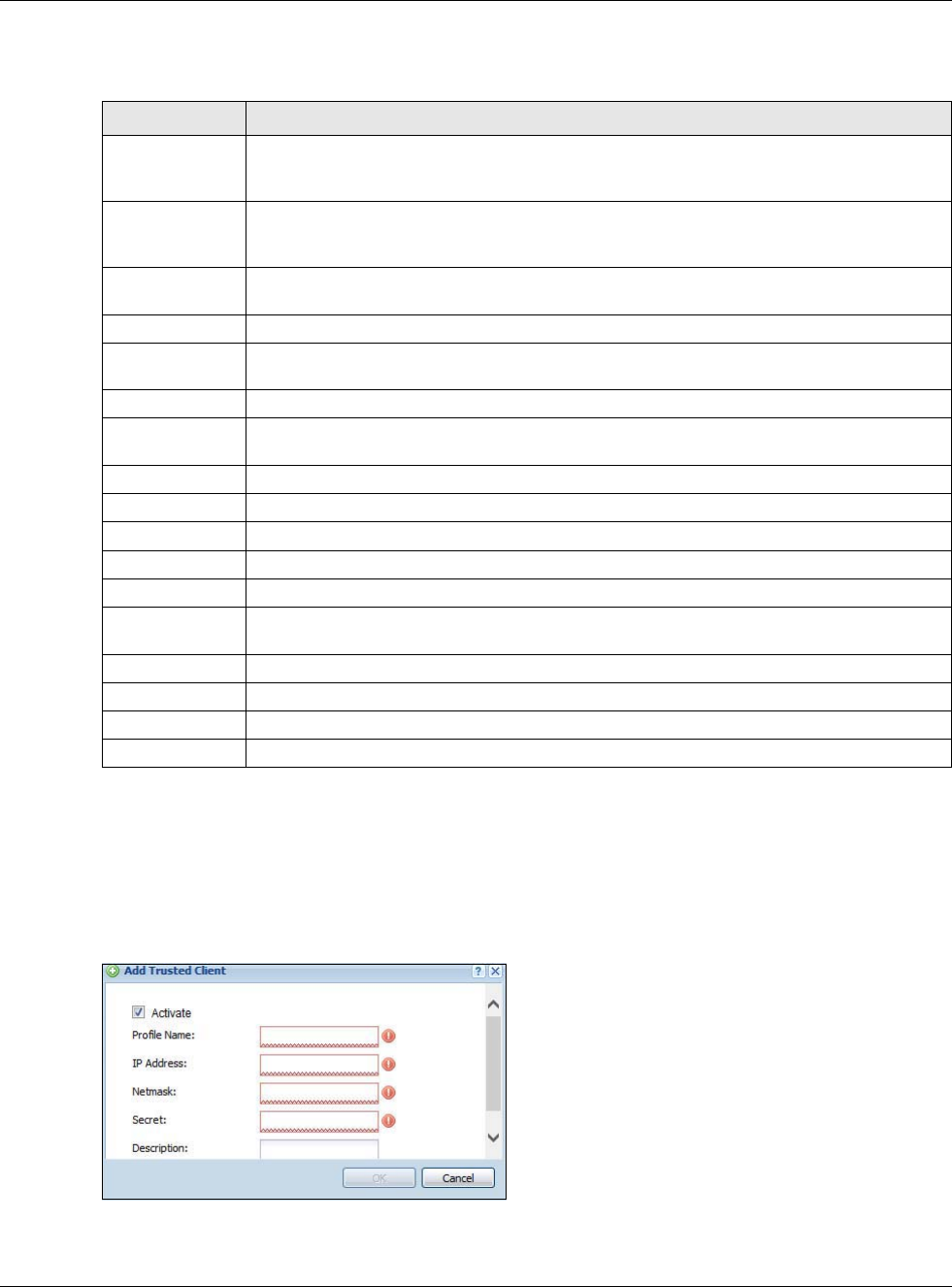
Chapter 30 System
USG20(W)-VPN Series User’s Guide
581
The following table describes the labels in this screen.
30.12.1 Add/Edit Trusted RADIUS Client
Click Configuration > System > Auth. Server to display the Auth. Server screen. Click the Add
icon or an Edit icon to display the following screen. Use this screen to create a new entry or edit an
existing one.
Figure 411 Configuration > System > Auth. Server > Add/Edit
Table 249 Configuration > System > Auth. Server
LABEL DESCRIPTION
Enable
Authentication
Server
Select the check box to have the USG act as a RADIUS server.
Authentication
Server
Certificate
Select the certificate whose corresponding private key is to be used to identify the USG to
the RADIUS client. You must have certificates already configured in the My Certificates
screen.
Authentication
Method
Select an authentication method if you have created any in the Configuration > Object >
Auth. Method screen.
Trusted Client Use this section to configure trusted clients in the USG RADIUS server database.
Add Click this to create a new entry. Select an entry and click Add to create a new entry after
the selected entry.
Edit Double-click an entry or select it and click Edit to be able to modify the entry’s settings.
Remove To remove an entry, select it and click Remove. The USG confirms you want to remove it
before doing so. Note that subsequent entries move up by one when you take this action.
Activate To turn on an entry, select it and click Activate.
Inactivate To turn off an entry, select it and click Inactivate.
#This is the index number of the entry.
Status This icon is lit when the entry is active and dimmed when the entry is inactive.
Profile Name This field indicates the name assigned to the profile.
IP Address This is the IP address of the RADIUS client that is allowed to exchange messages with the
USG.
Mask This is the subnet mask of the RADIUS client.
Description This is the description of the RADIUS client.
Apply Click Apply to save your changes back to the USG.
Reset Click Reset to return the screen to its last-saved settings.
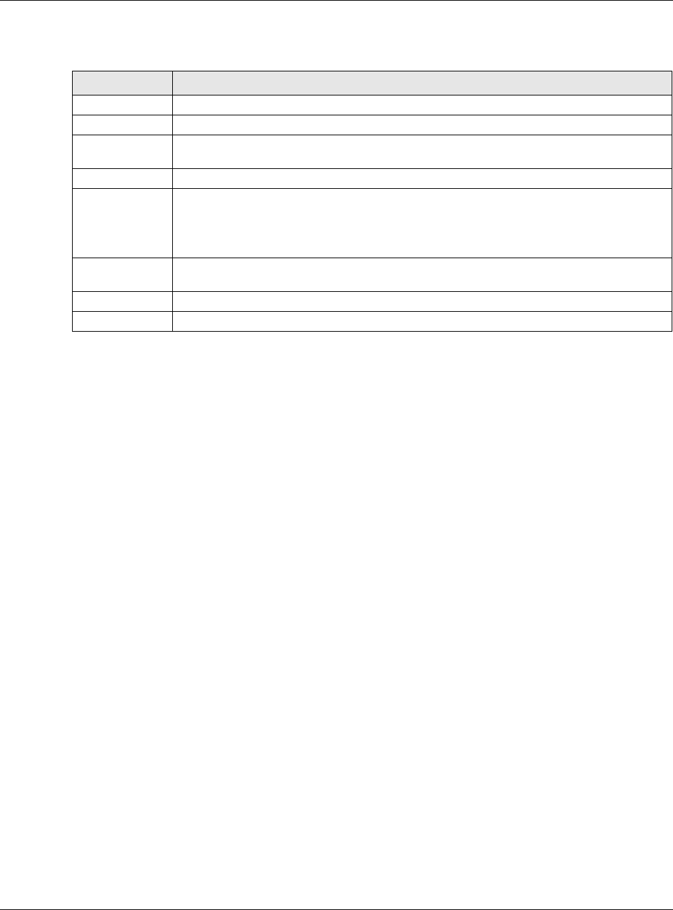
Chapter 30 System
USG20(W)-VPN Series User’s Guide
582
The following table describes the labels in this screen.
30.13 CloudCNM Screen
CloudCNM is a cloud-based network management system that allows management and monitoring
of ZyWALL/USG/UAG security gateways with firmware that supports the TR-069 protocol.
In the following figure, SP is the management service provider, while A and B are sites with devices
being managed by SP.
Table 250 Configuration > System > Auth. Server > Add/Edit
LABEL DESCRIPTION
Activate Select this check box to make this profile active.
Profile Name Enter a descriptive name (up to 31 alphanumerical characters) for identification purposes.
IP Address Enter the IP address of the RADIUS client that is allowed to exchange messages with the
USG.
Netmask Enter the subnet mask of the RADIUS client.
Secret Enter a password (up to 64 alphanumeric characters) as the key to be shared between the
USG and the RADIUS client.
The key is not sent over the network. This key must be the same on the external
authentication server and the USG.
Description Enter the description of each server, if any. You can use up to 60 printable ASCII
characters.
OK Click OK to save the changes.
Cancel Click Cancel to discard the changes.
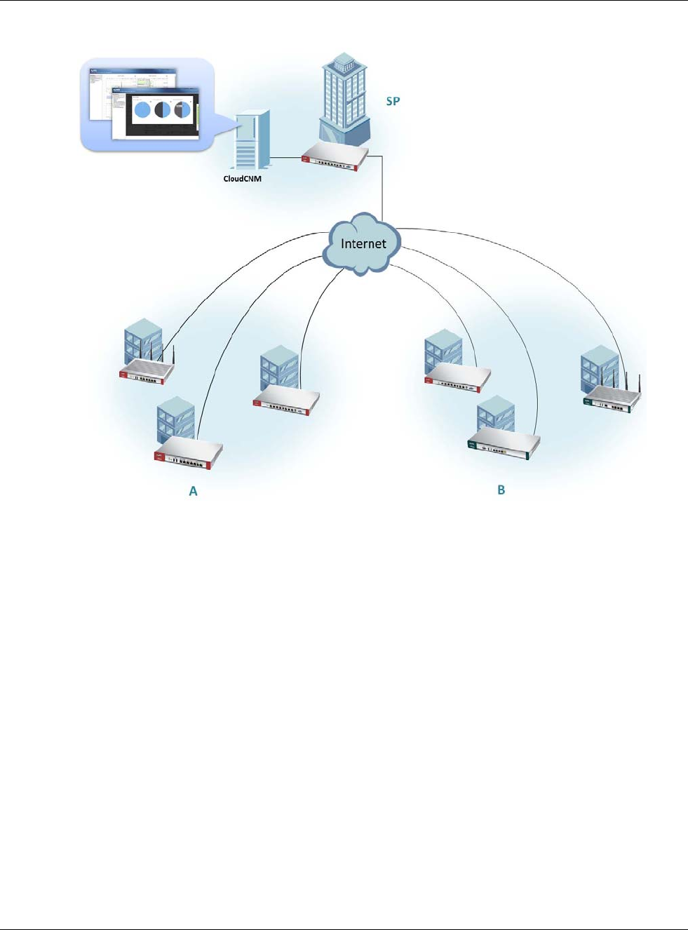
Chapter 30 System
USG20(W)-VPN Series User’s Guide
583
Figure 412 CloudCNM Example Network Topology
CloudCNM features include:
• Batch import of managed devices at one time using one CSV file
• See an overview of all managed devices and system information in one place
• Monitor and manage devices
• Install firmware to multiple devices of the same model at one time
• Backup and restore device configuration
• View the location of managed devices on a map
• Receive notification for events and alarms, such as when a device goes down
• Graphically monitor individual devices and see related statistics
• Directly access a device for remote configuration
• Create four types of administrators with different privileges
• Perform Site-to-Site, Hub & Spoke, Fully-meshed and Remote Access VPN provisioning.
To allow CloudCNM management of your USG:
• You must have a CloudCNM license with CNM ID number or a CloudCNM URL identifying the
server.
• The USG must be able to communicate with the CloudCNM server.
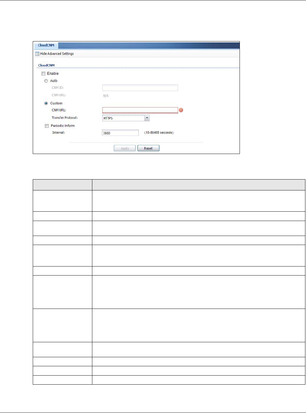
Chapter 30 System
USG20(W)-VPN Series User’s Guide
584
You must configure Configuration > System > CloudCNM to allow the USG to find the CloudCNM
server.
Figure 413 Configuration > System > CloudCNM
The following table describes the labels in this screen.
Note: See the CloudCNM User Guide for more information on CloudCNM.
Table 251 Configuration > System > CloudCNM
LABEL DESCRIPTION
Show Advanced
Settings / Hide
Advanced Settings
Click this button to display a greater or lesser number of configuration fields.
Enable Select this to allow management of the USG by CloudCNM.
Auto Select this if your CloudCNM server can access MyZyXEL.com and you have a CNM
ID from the CloudCNM license.
CNM ID Enter the CNM ID exactly as on the CloudCNM license.
CNM URL MyZyXEL.com associates the CNM ID with the CNM URL which identifies the server
on which CloudCNM is installed. Therefore you don’t need to enter the CNM URL when
you select Auto.
Custom Select this if your CloudCNM server cannot access MyZyXEL.com.
CNM URL If your USG server cannot access MyZyXEL.com, then select Custom and enter the
IPv4 IP address of the CloudCNM server followed by the port number (default 7547
for HTTPS or 7549 for HTPP) in CNM URL. For example, if you installed CloudCNM on
a server with IP address 1.1.1.1, then enter 1.1.1.1:7547 or 1.1.1.1:7549 as the
CNM URL.
Transfer Protocol Choose the CNM URL protocol: HTTP or HTTPS. If you enter 1.1.1.1:7547 as the
CNM URL, you must choose HTTPS as the Transfer Protocol, and then the whole
CNM URL is https://1.1.1.1:7547. If you enter 1.1.1.1:7549 as the CNM URL, you
must choose HTTP as the Transfer Protocol, and then the whole CNM URL is http:/
/1.1.1.1:7549.
Periodic Inform Enable this to have the USG inform the CloudCNM server of its presence at regular
intervals.
Interval Type how often the USG should inform CloudCNM server of its presence.
Apply Click Apply to save your changes back to the USG.
Reset Click Reset to return the screen to its last-saved settings.
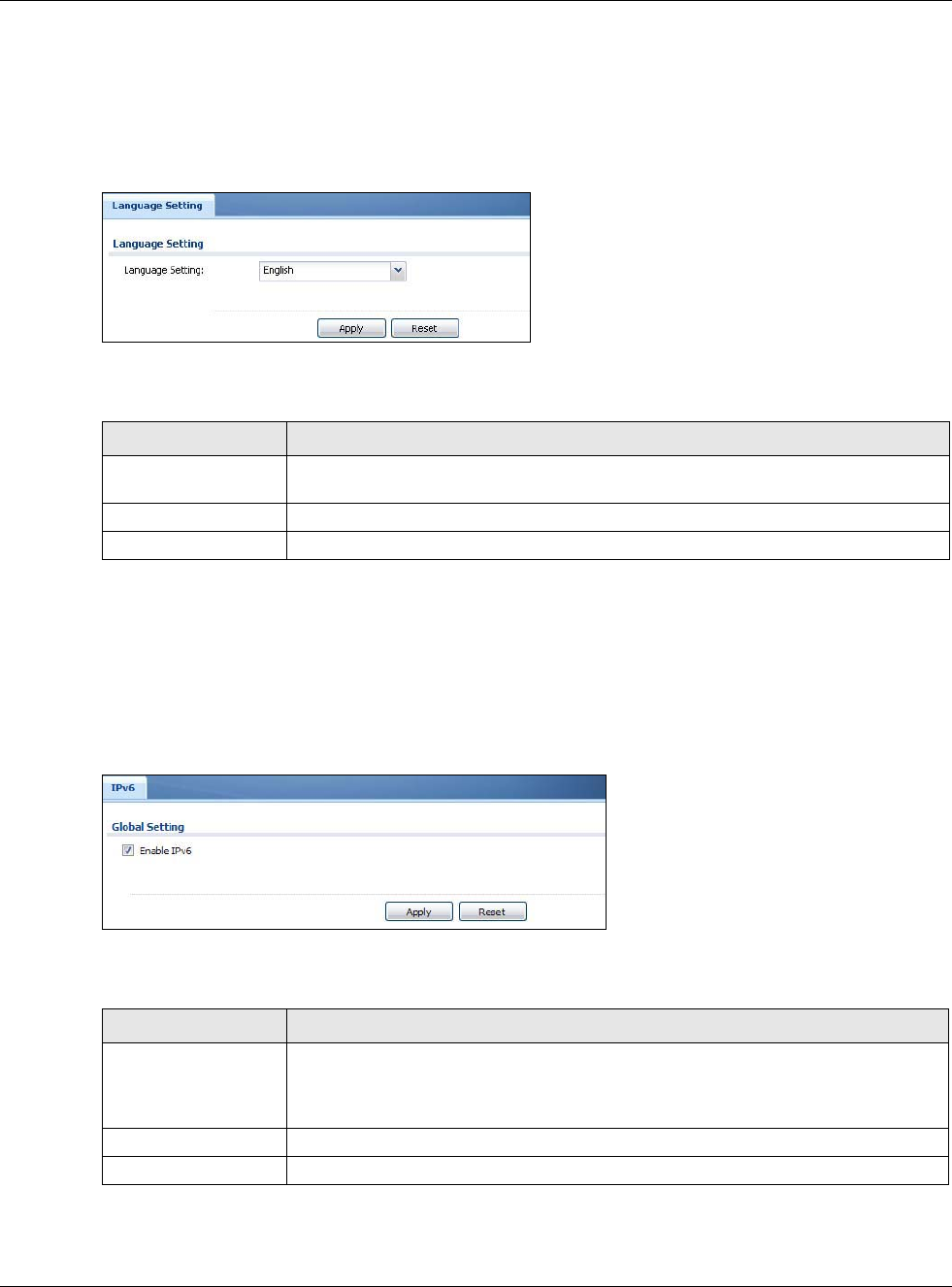
Chapter 30 System
USG20(W)-VPN Series User’s Guide
585
30.14 Language Screen
Click Configuration > System > Language to open the following screen. Use this screen to
select a display language for the USG’s Web Configurator screens.
Figure 414 Configuration > System > Language
The following table describes the labels in this screen.
30.15 IPv6 Screen
Click Configuration > System > IPv6 to open the following screen. Use this screen to enable
IPv6 support for the USG’s Web Configurator screens.
Figure 415 Configuration > System > IPv6
The following table describes the labels in this screen.
Table 252 Configuration > System > Language
LABEL DESCRIPTION
Language Setting Select a display language for the USG’s Web Configurator screens. You also need to
open a new browser session to display the screens in the new language.
Apply Click Apply to save your changes back to the USG.
Reset Click Reset to return the screen to its last-saved settings.
Table 253 Configuration > System > IPv6
LABEL DESCRIPTION
Enable IPv6 Select this to have the USG support IPv6 and make IPv6 settings be available on the
screens that the functions support, such as the Configuration > Network >
Interface > Ethernet, VLAN, and Bridge screens. The USG discards all IPv6
packets if you clear this check box.
Apply Click Apply to save your changes back to the USG.
Reset Click Reset to return the screen to its last-saved settings.
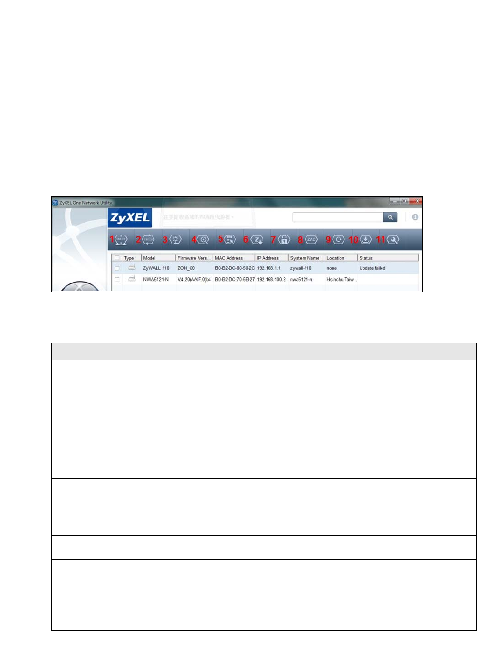
Chapter 30 System
USG20(W)-VPN Series User’s Guide
586
30.16 ZyXEL One Network (ZON) Utility
The ZyXEL One Network (ZON) utility uses the ZyXEL Discovery Protocol (ZDP) for discovering and
configuring ZDP-aware ZyXEL devices in the same broadcast domain as the computer on which
ZON is installed.
The ZON Utility issues requests via ZDP and in response to the query, the ZyXEL device responds
with basic information including IP address, firmware version, location, system and model name.
The information is then displayed in the ZON Utility screen and you can perform tasks like basic
configuration of the devices and batch firmware upgrade in it. You can download the ZON Utility at
www.zyxel.com and install it on a computer.
The following figure shows the ZON Utility screen.
Figure 416 ZON Utility Screen
In the ZON Utility, select a device and then use the icons to perform actions. The following table
describes the icons numbered from left to right in the ZON Utility screen.
Table 254 ZON Utility Icons
ICON DESCRIPTION
1 IP configuration Change the selected device’s IP address. This is not supported by the USG at the
time of writing.
2 Renew IP Update a DHCP-assigned dynamic IP address. This is not supported by the USG at
the time of writing.
3 Reboot Device Use this icon to restart the selected device(s). This may be useful when
troubleshooting or upgrading new firmware.
4 Flash Locator LED Use this icon to locate the selected device by causing its Locator LED to blink. This
is not available on the USG at the time of writing.
5 Web GUI Use this to access the selected device web configurator from your browser. You will
need a username and password to log in.
6 Firmware Upgrade Use this icon to upgrade new firmware to selected device(s) of the same model.
Make sure you have downloaded the firmware from the ZyXEL website to your
computer and unzipped it in advance.
7 Change Admin
Password
Use this icon to change the admin password of the selected device. You must know
the current admin password before changing to a new one.
8 ZAC Use this icon to run the ZyXEL AP Configurator of the selected AP. This is not
supported by the USG at the time of writing.
9 Discovery You should use this icon first to display all connected devices in the same network
as your computer.
10 Save Configuration Use this icon to save configuration changes to permanent memory on a selected
device. This is not needed by the USG at the time of writing.
11 Settings Use this icon to select a network adaptor for the computer on which the ZON utility
is installed, and the utility language.
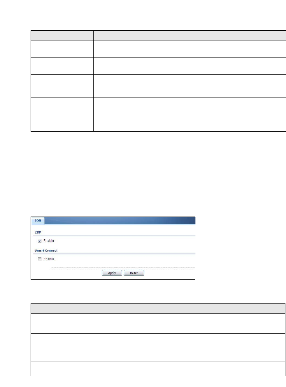
Chapter 30 System
USG20(W)-VPN Series User’s Guide
587
The following table describes the fields in the ZON Utility main screen.
30.16.1 ZyXEL One Network (ZON) System Screen
Enable ZDP (ZON) and Smart Connect (Ethernet Neighbor) in the System > ZON screen.
See Monitor > System Status > Ethernet Neighbor for information on using Smart Connect
(Link Layer Discovery Protocol (LLDP)) for discovering and configuring LLDP-aware devices in the
same broadcast domain as the USG that you’re logged into using the web configurator.
The following figure shows the System > ZON screen.
Figure 417 Configuration > System > ZON
The following table describes the labels in this screen.
Table 255 ZON Utility Fields
LABEL DESCRIPTION
Type This field displays an icon of the kind of device discovered.
Model This field displays the model name of the discovered device.
Firmware Version This field displays the firmware version of the discovered device.
MAC Address This field displays the MAC address of the discovered device.
IP Address This field displays the IP address of an internal interface on the discovered device
that first received an ZDP discovery request from the ZON utility.
System Name This field displays the system name of the discovered device.
Location This field displays where the discovered device is.
Status This field displays whether changes to the discovered device have been done
successfully. As the USG does not support IP Configuration, Renew IP address
and Flash Locator LED, this field displays “Update failed”, “Not support Renew IP
address” and “Not support Flash Locator LED” respectively.
Table 256 Configuration > System > ZON
LABEL DESCRIPTION
ZDP ZyXEL Discovery Protocol (ZDP) is the protocol that the ZyXEL One Network (ZON)
utility uses for discovering and configuring ZDP-aware ZyXEL devices in the same
broadcast domain as the computer on which ZON is installed.
Enable Select to activate ZDP discovery on the USG.
Smart Connect Smart Connect uses Link Layer Discovery Protocol (LLDP) for discovering and
configuring LLDP-aware devices in the same broadcast domain as the USG that
you’re logged into using the web configurator.
Enable Select to activate LLDP discovery on the USG. See also Monitor > System Status >
Ethernet Discovery.
Chapter 30 System
USG20(W)-VPN Series User’s Guide
588
Apply Click Apply to save your changes back to the USG.
Reset Click Reset to return the screen to its last-saved settings.
Table 256 Configuration > System > ZON
LABEL DESCRIPTION

USG20(W)-VPN Series User’s Guide
589
CHAPTER 31
Log and Report
31.1 Overview
Use these screens to configure daily reporting and log settings.
31.1.1 What You Can Do In this Chapter
•Use the Email Daily Report screen (Section 31.2 on page 589) to configure where and how to
send daily reports and what reports to send.
•Use the Log Setting screens (Section 31.3 on page 591) to specify settings for recording log
messages and alerts, e-mailing them, storing them on a connected USB storage device, and
sending them to remote syslog servers.
31.2 Email Daily Report
Use the Email Daily Report screen to start or stop data collection and view various statistics about
traffic passing through your USG.
Note: Data collection may decrease the USG’s traffic throughput rate.
Click Configuration > Log & Report > Email Daily Report to display the following screen.
Configure this screen to have the USG e-mail you system statistics every day.
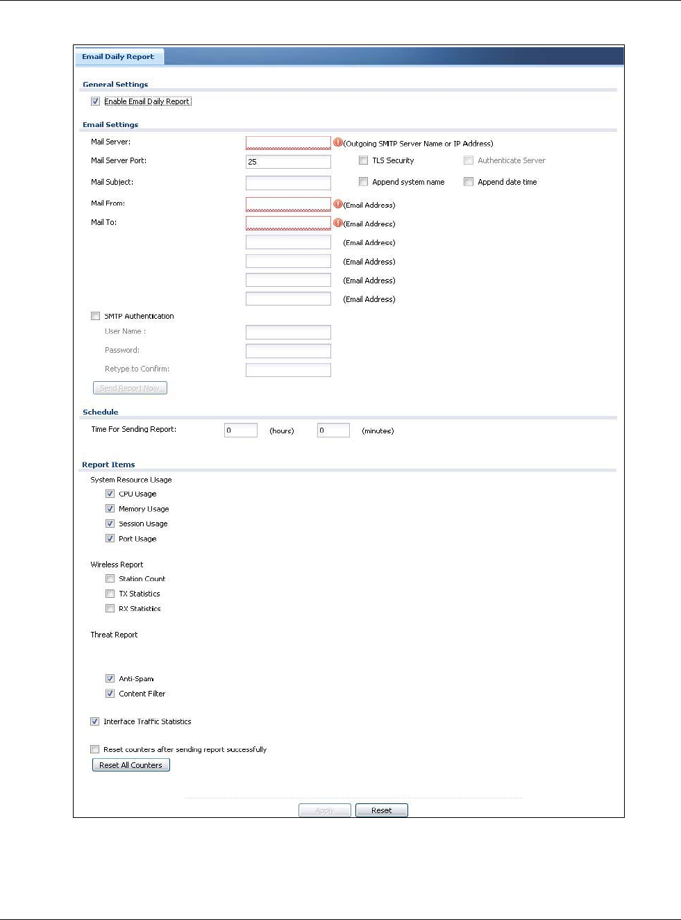
Chapter 31 Log and Report
USG20(W)-VPN Series User’s Guide
590
Figure 418 Configuration > Log & Report > Email Daily Report
Chapter 31 Log and Report
USG20(W)-VPN Series User’s Guide
591
The following table describes the labels in this screen.
31.3 Log Setting Screens
The Log Setting screens control log messages and alerts. A log message stores the information for
viewing or regular e-mailing later, and an alert is e-mailed immediately. Usually, alerts are used for
events that require more serious attention, such as system errors and attacks.
The USG provides a system log and supports e-mail profiles and remote syslog servers. View the
system log in the MONITOR > Log screen. Use the e-mail profiles to mail log messages to the
Table 257 Configuration > Log & Report > Email Daily Report
LABEL DESCRIPTION
Enable Email
Daily Report
Select this to send reports by e-mail every day.
Mail Server Type the name or IP address of the outgoing SMTP server.
Mail Server Port Enter the same port number here as is on the mail server for mail traffic.
TLS Security Select Transport Layer Security (TLS) if you want encrypted communications between the
mail server and the USG.
Authenticate
Server If you choose TLS Security, you may also select this to have the USG authenticate the
mail server in the TLS handshake.
Mail Subject Type the subject line for outgoing e-mail from the USG.
Append
system name Select Append system name to add the USG’s system name to the subject.
Append date
time Select Append date time to add the USG’s system date and time to the subject.
Mail From Type the e-mail address from which the outgoing e-mail is delivered. This address is used
in replies.
Mail To Type the e-mail address (or addresses) to which the outgoing e-mail is delivered.
SMTP
Authentication
Select this check box if it is necessary to provide a user name and password to the SMTP
server.
User Name This box is effective when you select the SMTP Authentication check box. Type the user
name to provide to the SMTP server when the log is e-mailed.
Password This box is effective when you select the SMTP Authentication check box. Type the
password to provide to the SMTP server when the log is e-mailed.
Retype to
Confirm Type the password again to make sure that you have entered is correctly.
Send Report Now Click this button to have the USG send the daily e-mail report immediately.
Time for sending
report
Select the time of day (hours and minutes) when the log is e-mailed. Use 24-hour
notation.
Report Items Select the information to include in the report. Types of information include System
Resource Usage, Wireless Report, Threat Report, and Interface Traffic Statistics.
Select Reset counters after sending report successfully if you only want to see
statistics for a 24 hour period.
Reset All
Counters
Click this to discard all report data and start all of the counters over at zero.
Apply Click Apply to save your changes back to the USG.
Reset Click Reset to return the screen to its last-saved settings.
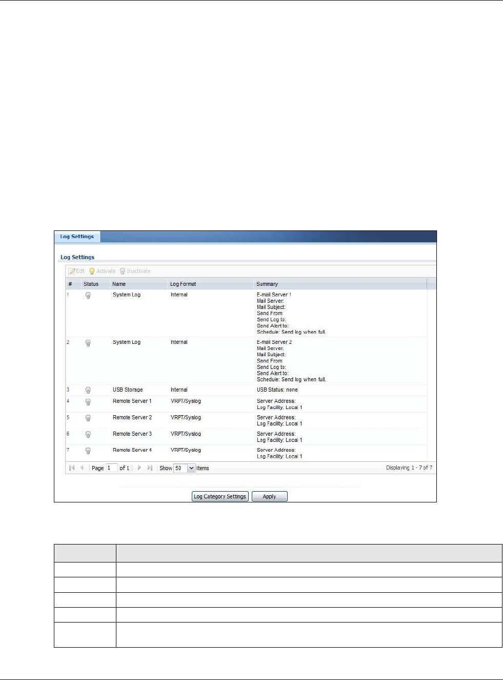
Chapter 31 Log and Report
USG20(W)-VPN Series User’s Guide
592
specific destinations. You can also have the USG store system logs on a connected USB storage
device. The other four logs are stored on specified syslog servers.
The Log Setting screens control what information the USG saves in each log. You can also specify
which log messages to e-mail for the system log, and where and how often to e-mail them. These
screens also set for which events to generate alerts and where to email the alerts.
The first Log Setting screen provides a settings summary. Use the Edit screens to configure
settings such as log categories, e-mail addresses, and server names for any log. Use the Log
Category Settings screen to edit what information is included in the system log, USB storage, e-
mail profiles, and remote servers.
31.3.1 Log Settings
To access this screen, click Configuration > Log & Report > Log Settings.
Figure 419 Configuration > Log & Report > Log Settings
The following table describes the labels in this screen.
Table 258 Configuration > Log & Report > Log Settings
LABEL DESCRIPTION
Edit Double-click an entry or select it and click Edit to open a screen where you can modify it.
Activate To turn on an entry, select it and click Activate.
Inactivate To turn off an entry, select it and click Inactivate.
# This field is a sequential value, and it is not associated with a specific log.
Name This field displays the type of log setting entry (system log, logs stored on a USB storage
device connected to the USG, or one of the remote servers).
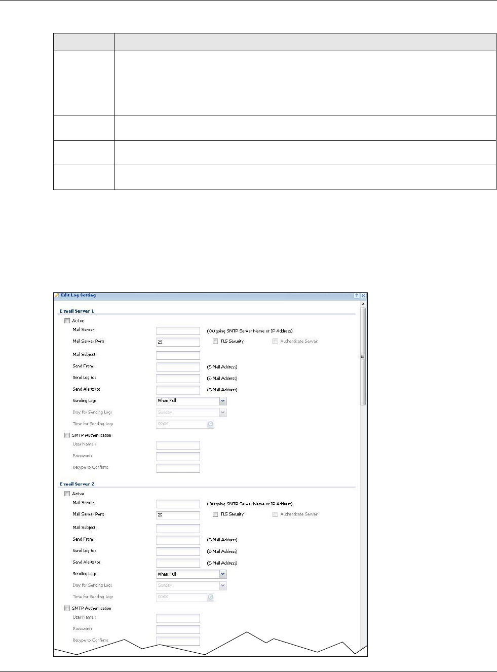
Chapter 31 Log and Report
USG20(W)-VPN Series User’s Guide
593
31.3.2 Edit System Log Settings
The Log Settings Edit screen controls the detailed settings for each log in the system log (which
includes the e-mail profiles). Go to the Log Settings screen (see Section 31.3.1 on page 592), and
click the system log Edit icon.
Figure 420 Configuration > Log & Report > Log Setting > Edit (System Log)
Log Format This field displays the format of the log.
Internal - system log; you can view the log on the View Log tab.
VRPT/Syslog - ZyXEL’s Vantage Report, syslog-compatible format.
CEF/Syslog - Common Event Format, syslog-compatible format.
Summary This field is a summary of the settings for each log. Please see Section 31.3.2 on page 593 for
more information.
Log Category
Settings
Click this button to open the Log Category Settings Edit screen.
Apply Click this button to save your changes (activate and deactivate logs) and make them take
effect.
Table 258 Configuration > Log & Report > Log Settings (continued)
LABEL DESCRIPTION
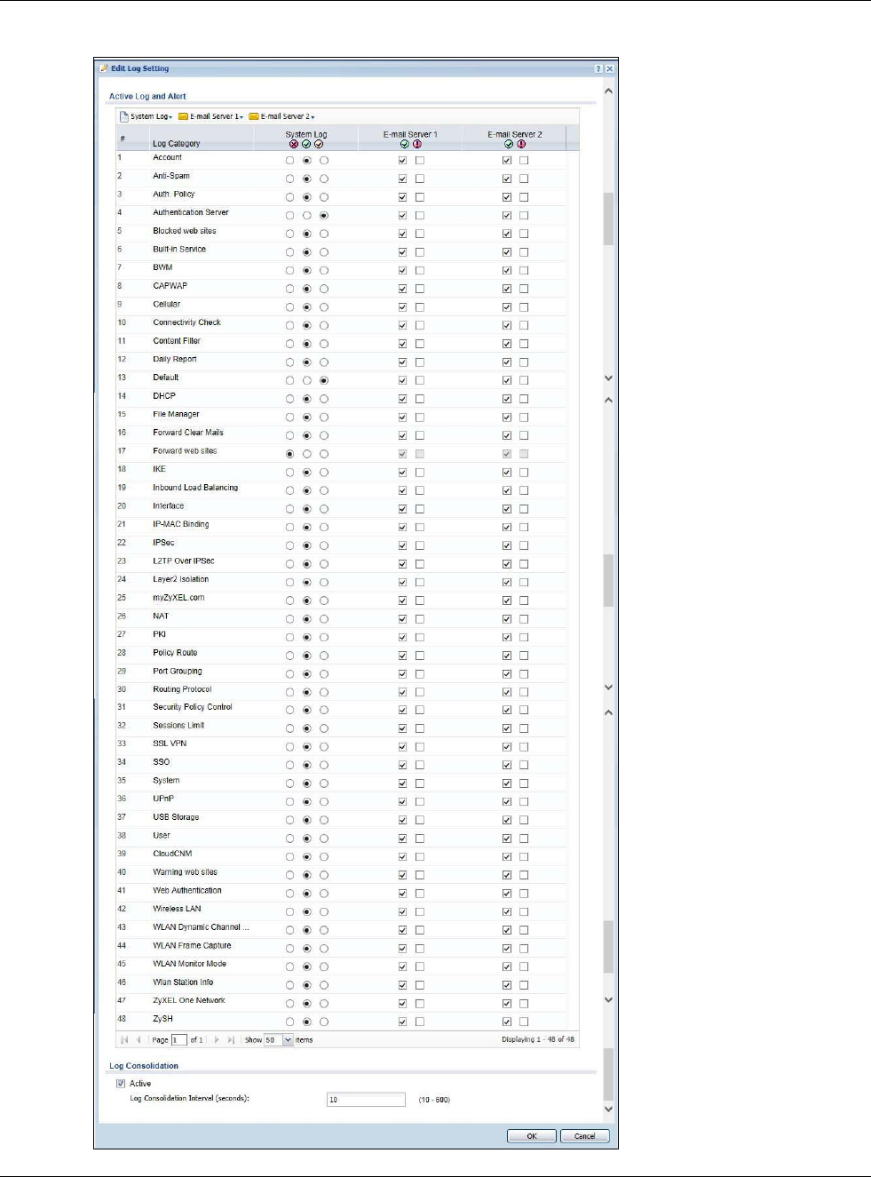
Chapter 31 Log and Report
USG20(W)-VPN Series User’s Guide
594
Figure 421 Configuration > Log & Report > Log Setting > Edit (System Log)
Chapter 31 Log and Report
USG20(W)-VPN Series User’s Guide
595
The following table describes the labels in this screen.
Table 259 Configuration > Log & Report > Log Setting > Edit (System Log)
LABEL DESCRIPTION
E-Mail Server 1/2
Active Select this to send log messages and alerts according to the information in this
section. You specify what kinds of log messages are included in log information and
what kinds of log messages are included in alerts in the Active Log and Alert
section.
Mail Server Type the name or IP address of the outgoing SMTP server.
Mail Subject Type the subject line for the outgoing e-mail.
Send From Type the e-mail address from which the outgoing e-mail is delivered. This address is
used in replies.
Send Log To Type the e-mail address to which the outgoing e-mail is delivered.
Send Alerts To Type the e-mail address to which alerts are delivered.
Sending Log Select how often log information is e-mailed. Choices are: When Full, Hourly and
When Full, Daily and When Full, and Weekly and When Full.
Day for Sending
Log This field is available if the log is e-mailed weekly. Select the day of the week the log
is e-mailed.
Time for Sending
Log This field is available if the log is e-mailed weekly or daily. Select the time of day
(hours and minutes) when the log is e-mailed. Use 24-hour notation.
SMTP
Authentication Select this check box if it is necessary to provide a user name and password to the
SMTP server.
User Name This box is effective when you select the SMTP Authentication check box. Type the
user name to provide to the SMTP server when the log is e-mailed.
Password This box is effective when you select the SMTP Authentication check box. Type the
password to provide to the SMTP server when the log is e-mailed.
Retype to Confirm Type the password again to make sure that you have entered is correctly.
Active Log and Alert
System Log Use the System Log drop-down list to change the log settings for all of the log
categories.
disable all logs (red X) - do not log any information for any category for the system
log or e-mail any logs to e-mail server 1 or 2.
enable normal logs (green check mark) - create log messages and alerts for all
categories for the system log. If e-mail server 1 or 2 also has normal logs enabled,
the USG will e-mail logs to them.
enable normal logs and debug logs (yellow check mark) - create log messages,
alerts, and debugging information for all categories. The USG does not e-mail
debugging information, even if this setting is selected.
E-mail Server 1 Use the E-Mail Server 1 drop-down list to change the settings for e-mailing logs to
e-mail server 1 for all log categories.
Using the System Log drop-down list to disable all logs overrides your e-mail server
1 settings.
enable normal logs (green check mark) - e-mail log messages for all categories to
e-mail server 1.
enable alert logs (red exclamation point) - e-mail alerts for all categories to e-mail
server 1.
Chapter 31 Log and Report
USG20(W)-VPN Series User’s Guide
596
31.3.3 Edit Log on USB Storage Setting
The Edit Log on USB Storage Setting screen controls the detailed settings for saving logs to a
connected USB storage device. Go to the Log Setting Summary screen (see Section 31.3.1 on
page 592), and click the USB storage Edit icon.
E-mail Server 2 Use the E-Mail Server 2 drop-down list to change the settings for e-mailing logs to
e-mail server 2 for all log categories.
Using the System Log drop-down list to disable all logs overrides your e-mail server
2 settings.
enable normal logs (green check mark) - e-mail log messages for all categories to
e-mail server 2.
enable alert logs (red exclamation point) - e-mail alerts for all categories to e-mail
server 2.
# This field is a sequential value, and it is not associated with a specific address.
Log Category This field displays each category of messages. It is the same value used in the
Display and Category fields in the View Log tab. The Default category includes
debugging messages generated by open source software.
System log Select which events you want to log by Log Category. There are three choices:
disable all logs (red X) - do not log any information from this category
enable normal logs (green check mark) - create log messages and alerts from this
category
enable normal logs and debug logs (yellow check mark) - create log messages,
alerts, and debugging information from this category; the USG does not e-mail
debugging information, however, even if this setting is selected.
E-mail Server 1 Select whether each category of events should be included in the log messages when
it is e-mailed (green check mark) and/or in alerts (red exclamation point) for the e-
mail settings specified in E-Mail Server 1. The USG does not e-mail debugging
information, even if it is recorded in the System log.
E-mail Server 2 Select whether each category of events should be included in log messages when it is
e-mailed (green check mark) and/or in alerts (red exclamation point) for the e-mail
settings specified in E-Mail Server 2. The USG does not e-mail debugging
information, even if it is recorded in the System log.
Log Consolidation
Active Select this to activate log consolidation. Log consolidation aggregates multiple log
messages that arrive within the specified Log Consolidation Interval. In the View
Log tab, the text “[count=x]”, where x is the number of original log messages, is
appended at the end of the Message field, when multiple log messages were
aggregated.
Log Consolidation
Interval Type how often, in seconds, to consolidate log information. If the same log message
appears multiple times, it is aggregated into one log message with the text
“[count=x]”, where x is the number of original log messages, appended at the end of
the Message field.
OK Click this to save your changes and return to the previous screen.
Cancel Click this to return to the previous screen without saving your changes.
Table 259 Configuration > Log & Report > Log Setting > Edit (System Log) (continued)
LABEL DESCRIPTION
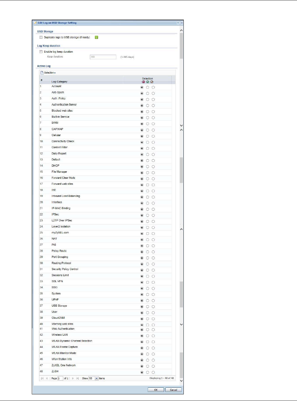
Chapter 31 Log and Report
USG20(W)-VPN Series User’s Guide
597
Figure 422 Configuration > Log & Report > Log Setting > Edit (USB Storage)
Chapter 31 Log and Report
USG20(W)-VPN Series User’s Guide
598
The following table describes the labels in this screen.
31.3.4 Edit Remote Server Log Settings
The Log Settings Edit screen controls the detailed settings for each log in the remote server
(syslog). Go to the Log Settings Summary screen (see Section 31.3.1 on page 592), and click a
remote server Edit icon.
Table 260 Configuration > Log & Report > Log Setting > Edit (USB Storage)
LABEL DESCRIPTION
USB Storage
Duplicate logs to
USB storage (if
ready)
Select this to have the USG save a copy of its system logs to a connected USB storage
device. Use the Active Log section to specify what kinds of messages to include.
Log Keep
duration
Enable log keep
duration
Select this and enter the number of days you want the USG to store a log in Keep
duration before deleting it forever from the USG.
Active Log
Selection Use the Selection drop-down list to change the log settings for all of the log categories.
disable all logs (red X) - do not send the remote server logs for any log category.
enable normal logs (green check mark) - send the remote server log messages and
alerts for all log categories.
enable normal logs and debug logs (yellow check mark) - send the remote server log
messages, alerts, and debugging information for all log categories.
# This field is a sequential value, and it is not associated with a specific entry.
Log Category This field displays each category of messages. The Default category includes debugging
messages generated by open source software.
Selection Select what information you want to log from each Log Category (except All Logs; see
below). Choices are:
disable all logs (red X) - do not log any information from this category
enable normal logs (green check mark) - log regular information and alerts from this
category
enable normal logs and debug logs (yellow check mark) - log regular information,
alerts, and debugging information from this category
OK Click this to save your changes and return to the previous screen.
Cancel Click this to return to the previous screen without saving your changes.
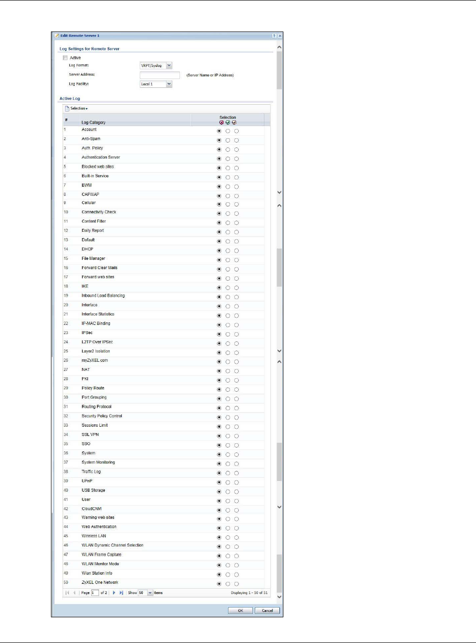
Chapter 31 Log and Report
USG20(W)-VPN Series User’s Guide
599
Figure 423 Configuration > Log & Report > Log Setting > Edit (Remote Server)
Chapter 31 Log and Report
USG20(W)-VPN Series User’s Guide
600
The following table describes the labels in this screen.
31.3.5 Log Category Settings Screen
The Log Category Settings screen allows you to view and to edit what information is included in
the system log, USB storage, e-mail profiles, and remote servers at the same time. It does not let
you change other log settings (for example, where and how often log information is e-mailed or
remote server names). To access this screen, go to the Log Settings screen (see Section 31.3.1 on
page 592), and click the Log Category Settings button.
Table 261 Configuration > Log & Report > Log Setting > Edit (Remote Server)
LABEL DESCRIPTION
Log Settings for
Remote Server
Active Select this check box to send log information according to the information in this section.
You specify what kinds of messages are included in log information in the Active Log
section.
Log Format This field displays the format of the log information. It is read-only.
VRPT/Syslog - ZyXEL’s Vantage Report, syslog-compatible format.
CEF/Syslog - Common Event Format, syslog-compatible format.
Server
Address Type the server name or the IP address of the syslog server to which to send log
information.
Log Facility Select a log facility. The log facility allows you to log the messages to different files in the
syslog server. Please see the documentation for your syslog program for more information.
Active Log
Selection Use the Selection drop-down list to change the log settings for all of the log categories.
disable all logs (red X) - do not send the remote server logs for any log category.
enable normal logs (green check mark) - send the remote server log messages and alerts
for all log categories.
enable normal logs and debug logs (yellow check mark) - send the remote server log
messages, alerts, and debugging information for all log categories.
# This field is a sequential value, and it is not associated with a specific address.
Log
Category This field displays each category of messages. It is the same value used in the Display and
Category fields in the View Log tab. The Default category includes debugging messages
generated by open source software.
Selection Select what information you want to log from each Log Category (except All Logs; see
below). Choices are:
disable all logs (red X) - do not log any information from this category
enable normal logs (green check mark) - log regular information and alerts from this
category
enable normal logs and debug logs (yellow check mark) - log regular information, alerts,
and debugging information from this category
OK Click this to save your changes and return to the previous screen.
Cancel Click this to return to the previous screen without saving your changes.
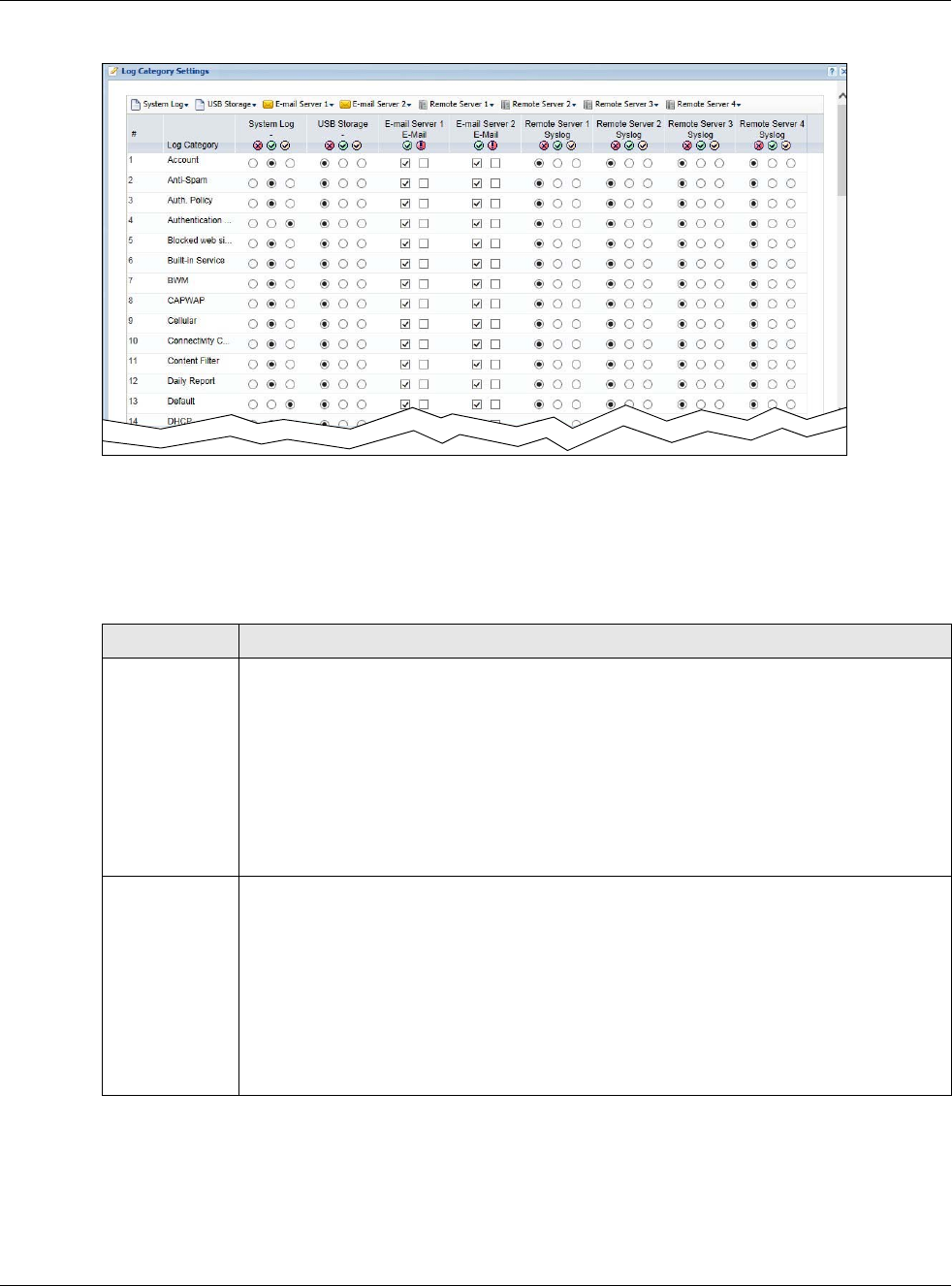
Chapter 31 Log and Report
USG20(W)-VPN Series User’s Guide
601
Figure 424 Log Category Settings AC
This screen provides a different view and a different way of indicating which messages are included
in each log and each alert. Please see Section 31.3.2 on page 593, where this process is discussed.
(The Default category includes debugging messages generated by open source software.)
The following table describes the fields in this screen.
Table 262 Configuration > Log & Report > Log Setting > Log Category Settings
LABEL DESCRIPTION
System Log Use the System Log drop-down list to change the log settings for all of the log categories.
disable all logs (red X) - do not log any information for any category for the system log or
e-mail any logs to e-mail server 1 or 2.
enable normal logs (green check mark) - create log messages and alerts for all categories
for the system log. If e-mail server 1 or 2 also has normal logs enabled, the USG will e-mail
logs to them.
enable normal logs and debug logs (yellow check mark) - create log messages, alerts,
and debugging information for all categories. The USG does not e-mail debugging
information, even if this setting is selected.
USB Storage Use the USB Storage drop-down list to change the log settings for saving logs to a
connected USB storage device.
disable all logs (red X) - do not log any information for any category to a connected USB
storage device.
enable normal logs (green check mark) - create log messages and alerts for all categories
and save them to a connected USB storage device.
enable normal logs and debug logs (yellow check mark) - create log messages, alerts,
and debugging information for all categories and save them to a connected USB storage
device.
Chapter 31 Log and Report
USG20(W)-VPN Series User’s Guide
602
E-mail Server 1 Use the E-Mail Server 1 drop-down list to change the settings for e-mailing logs to e-mail
server 1 for all log categories.
Using the System Log drop-down list to disable all logs overrides your e-mail server 1
settings.
enable normal logs (green check mark) - e-mail log messages for all categories to e-mail
server 1.
enable alert logs (red exclamation point) - e-mail alerts for all categories to e-mail server
1.
E-mail Server 2 Use the E-Mail Server 2 drop-down list to change the settings for e-mailing logs to e-mail
server 2 for all log categories.
Using the System Log drop-down list to disable all logs overrides your e-mail server 2
settings.
enable normal logs (green check mark) - e-mail log messages for all categories to e-mail
server 2.
enable alert logs (red exclamation point) - e-mail alerts for all categories to e-mail server
2.
Remote Server
1~4
For each remote server, use the Selection drop-down list to change the log settings for all
of the log categories.
disable all logs (red X) - do not send the remote server logs for any log category.
enable normal logs (green check mark) - send the remote server log messages and alerts
for all log categories.
enable normal logs and debug logs (yellow check mark) - send the remote server log
messages, alerts, and debugging information for all log categories.
# This field is a sequential value, and it is not associated with a specific address.
Log Category This field displays each category of messages. It is the same value used in the Display and
Category fields in the View Log tab. The Default category includes debugging messages
generated by open source software.
System Log Select which events you want to log by Log Category. There are three choices:
disable all logs (red X) - do not log any information from this category
enable normal logs (green check mark) - create log messages and alerts from this
category
enable normal logs and debug logs (yellow check mark) - create log messages, alerts,
and debugging information from this category; the USG does not e-mail debugging
information, however, even if this setting is selected.
USB Storage Select which event log categories to save to a connected USB storage device. There are
three choices:
disable all logs (red X) - do not log any information from this category
enable normal logs (green check mark) - save log messages and alerts from this category
enable normal logs and debug logs (yellow check mark) - save log messages, alerts,
and debugging information from this category.
E-mail Server 1
E-mail
Select whether each category of events should be included in the log messages when it is e-
mailed (green check mark) and/or in alerts (red exclamation point) for the e-mail settings
specified in E-Mail Server 1. The USG does not e-mail debugging information, even if it is
recorded in the System log.
Table 262 Configuration > Log & Report > Log Setting > Log Category Settings (continued)
LABEL DESCRIPTION
Chapter 31 Log and Report
USG20(W)-VPN Series User’s Guide
603
E-mail Server 2
E-mail
Select whether each category of events should be included in log messages when it is e-
mailed (green check mark) and/or in alerts (red exclamation point) for the e-mail settings
specified in E-Mail Server 2. The USG does not e-mail debugging information, even if it is
recorded in the System log.
Remote Server
1~4
For each remote server, select what information you want to log from each Log Category
(except All Logs; see below). Choices are:
disable all logs (red X) - do not log any information from this category
enable normal logs (green check mark) - log regular information and alerts from this
category
enable normal logs and debug logs (yellow check mark) - log regular information,
alerts, and debugging information from this category
OK Click this to save your changes and return to the previous screen.
Cancel Click this to return to the previous screen without saving your changes.
Table 262 Configuration > Log & Report > Log Setting > Log Category Settings (continued)
LABEL DESCRIPTION

USG20(W)-VPN Series User’s Guide
604
CHAPTER 32
File Manager
32.1 Overview
Configuration files define the USG’s settings. Shell scripts are files of commands that you can store
on the USG and run when you need them. You can apply a configuration file or run a shell script
without the USG restarting. You can store multiple configuration files and shell script files on the
USG. You can edit configuration files or shell scripts in a text editor and upload them to the USG.
Configuration files use a .conf extension and shell scripts use a .zysh extension.
32.1.1 What You Can Do in this Chapter
•Use the Configuration File screen (see Section 32.2 on page 606) to store and name
configuration files. You can also download configuration files from the USG to your computer and
upload configuration files from your computer to the USG.
•Use the Firmware Package screen (see Section 32.3 on page 610) to check your current
firmware version and upload firmware to the USG.
•Use the Shell Script screen (see Section 32.4 on page 612) to store, name, download, upload
and run shell script files.
32.1.2 What you Need to Know
Configuration Files and Shell Scripts
When you apply a configuration file, the USG uses the factory default settings for any features that
the configuration file does not include. When you run a shell script, the USG only applies the
commands that it contains. Other settings do not change.
Chapter 32 File Manager
USG20(W)-VPN Series User’s Guide
605
These files have the same syntax, which is also identical to the way you run CLI commands
manually. An example is shown below.
While configuration files and shell scripts have the same syntax, the USG applies configuration files
differently than it runs shell scripts. This is explained below.
You have to run the example in Figure 425 on page 605 as a shell script because the first command
is run in Privilege mode. If you remove the first command, you have to run the example as a
configuration file because the rest of the commands are executed in Configuration mode.
Comments in Configuration Files or Shell Scripts
In a configuration file or shell script, use “#” or “!” as the first character of a command line to have
the USG treat the line as a comment.
Your configuration files or shell scripts can use “exit” or a command line consisting of a single “!” to
have the USG exit sub command mode.
Note: “exit” or “!'” must follow sub commands if it is to make the USG exit sub command
mode.
Figure 425 Configuration File / Shell Script: Example
# enter configuration mode
configure terminal
# change administrator password
username admin password 4321 user-type admin
# configure ge3
interface ge3
ip address 172.23.37.240 255.255.255.0
ip gateway 172.23.37.254 metric 1
exit
# create address objects for remote management / to-ZyWALL firewall rules
# use the address group in case we want to open up remote management later
address-object TW_SUBNET 172.23.37.0/24
object-group address TW_TEAM
address-object TW_SUBNET
exit
# enable Telnet access (not enabled by default, unlike other services)
ip telnet server
# open WAN-to-ZyWALL firewall for TW_TEAM for remote management
firewall WAN ZyWALL insert 4
sourceip TW_TEAM
service TELNET
action allow
exit
write
Table 263 Configuration Files and Shell Scripts in the USG
Configuration Files (.conf) Shell Scripts (.zysh)
• Resets to default configuration.
•Goes into CLI Configuration mode.
• Runs the commands in the configuration file.
•Goes into CLI Privilege mode.
• Runs the commands in the shell script.
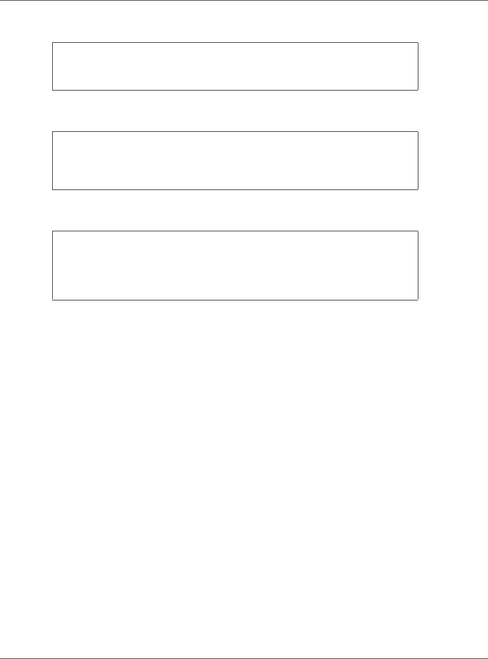
Chapter 32 File Manager
USG20(W)-VPN Series User’s Guide
606
Line 3 in the following example exits sub command mode.
Lines 1 and 3 in the following example are comments and line 4 exits sub command mode.
Lines 1 and 2 are comments. Line 5 exits sub command mode.
Errors in Configuration Files or Shell Scripts
When you apply a configuration file or run a shell script, the USG processes the file line-by-line. The
USG checks the first line and applies the line if no errors are detected. Then it continues with the
next line. If the USG finds an error, it stops applying the configuration file or shell script and
generates a log.
You can change the way a configuration file or shell script is applied. Include setenv stop-on-
error off in the configuration file or shell script. The USG ignores any errors in the configuration
file or shell script and applies all of the valid commands. The USG still generates a log for any
errors.
32.2 The Configuration File Screen
Click Maintenance > File Manager > Configuration File to open the Configuration File
screen. Use the Configuration File screen to store, run, and name configuration files. You can also
download configuration files from the USG to your computer and upload configuration files from
your computer to the USG.
Once your USG is configured and functioning properly, it is highly recommended that you back up
your configuration file before making further configuration changes. The backup configuration file
will be useful in case you need to return to your previous settings.
interface ge1
ip address dhcp
!
!
interface ge1
# this interface is a DHCP client
!
! this is from Joe
# on 2008/04/05
interface ge1
ip address dhcp
!
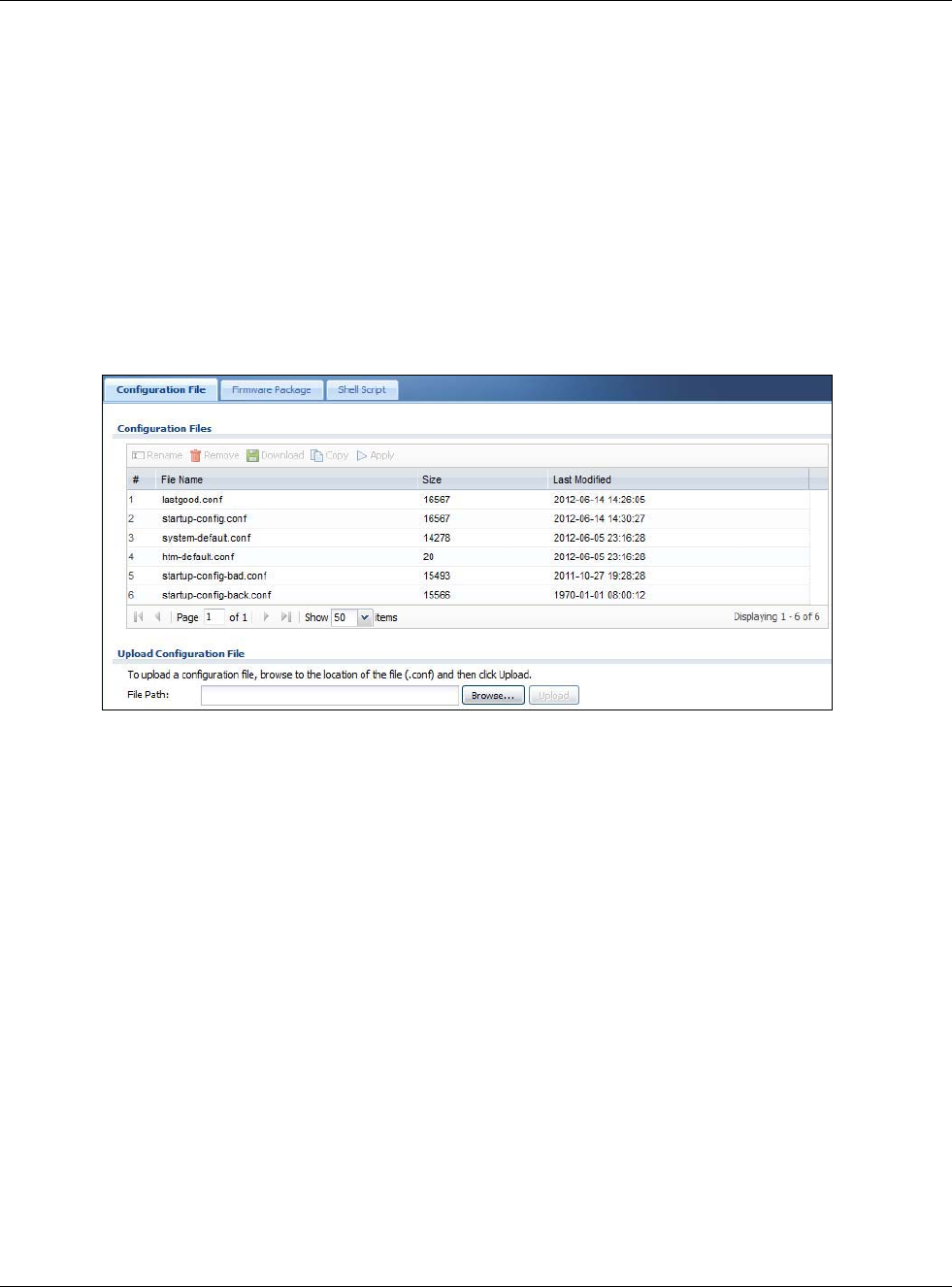
Chapter 32 File Manager
USG20(W)-VPN Series User’s Guide
607
Configuration File Flow at Restart
• If there is not a startup-config.conf when you restart the USG (whether through a
management interface or by physically turning the power off and back on), the USG uses the
system-default.conf configuration file with the USG’s default settings.
•If there is a startup-config.conf, the USG checks it for errors and applies it. If there are no
errors, the USG uses it and copies it to the lastgood.conf configuration file as a back up file. If
there is an error, the USG generates a log and copies the startup-config.conf configuration file
to the startup-config-bad.conf configuration file and tries the existing lastgood.conf
configuration file. If there isn’t a lastgood.conf configuration file or it also has an error, the USG
applies the system-default.conf configuration file.
• You can change the way the startup-config.conf file is applied. Include the setenv-startup
stop-on-error off command. The USG ignores any errors in the startup-config.conf file and
applies all of the valid commands. The USG still generates a log for any errors.
Figure 426 Maintenance > File Manager > Configuration File
Do not turn off the USG while configuration file upload is in progress.
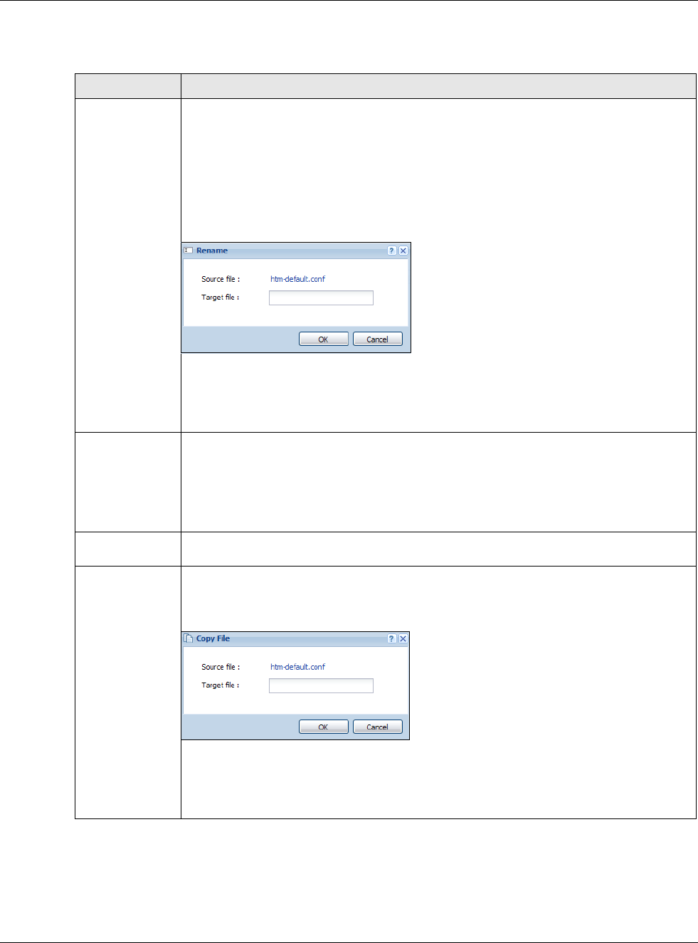
Chapter 32 File Manager
USG20(W)-VPN Series User’s Guide
608
The following table describes the labels in this screen.
Table 264 Maintenance > File Manager > Configuration File
LABEL DESCRIPTION
Rename Use this button to change the label of a configuration file on the USG. You can only rename
manually saved configuration files. You cannot rename the lastgood.conf, system-
default.conf and startup-config.conf files.
You cannot rename a configuration file to the name of another configuration file in the
USG.
Click a configuration file’s row to select it and click Rename to open the Rename File
screen.
Figure 427 Maintenance > File Manager > Configuration File > Rename
Specify the new name for the configuration file. Use up to 25 characters (including a-zA-
Z0-9;‘~!@#$%^&()_+[]{}’,.=-).
Click OK to save the duplicate or click Cancel to close the screen without saving a
duplicate of the configuration file.
Remove Click a configuration file’s row to select it and click Remove to delete it from the USG. You
can only delete manually saved configuration files. You cannot delete the system-
default.conf, startup-config.conf and lastgood.conf files.
A pop-up window asks you to confirm that you want to delete the configuration file. Click
OK to delete the configuration file or click Cancel to close the screen without deleting the
configuration file.
Download Click a configuration file’s row to select it and click Download to save the configuration to
your computer.
Copy Use this button to save a duplicate of a configuration file on the USG.
Click a configuration file’s row to select it and click Copy to open the Copy File screen.
Figure 428 Maintenance > File Manager > Configuration File > Copy
Specify a name for the duplicate configuration file. Use up to 25 characters (including a-
zA-Z0-9;‘~!@#$%^&()_+[]{}’,.=-).
Click OK to save the duplicate or click Cancel to close the screen without saving a
duplicate of the configuration file.
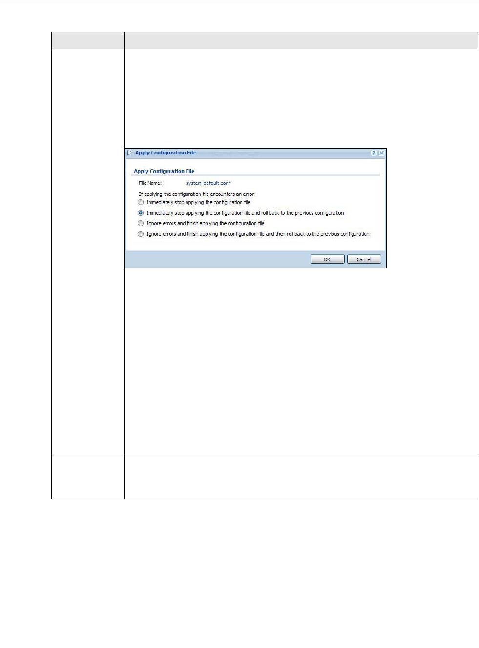
Chapter 32 File Manager
USG20(W)-VPN Series User’s Guide
609
Apply Use this button to have the USG use a specific configuration file.
Click a configuration file’s row to select it and click Apply to have the USG use that
configuration file. The USG does not have to restart in order to use a different
configuration file, although you will need to wait for a few minutes while the system
reconfigures.
The following screen gives you options for what the USG is to do if it encounters an error in
the configuration file.
Figure 429 Maintenance > File Manager > Configuration File > Apply
Immediately stop applying the configuration file - this is not recommended because
it would leave the rest of the configuration blank. If the interfaces were not configured
before the first error, the console port may be the only way to access the device.
Immediately stop applying the configuration file and roll back to the previous
configuration - this gets the USG started with a fully valid configuration file as quickly as
possible.
Ignore errors and finish applying the configuration file - this applies the valid parts
of the configuration file and generates error logs for all of the configuration file’s errors.
This lets the USG apply most of your configuration and you can refer to the logs for what
to fix.
Ignore errors and finish applying the configuration file and then roll back to the
previous configuration - this applies the valid parts of the configuration file, generates
error logs for all of the configuration file’s errors, and starts the USG with a fully valid
configuration file.
Click OK to have the USG start applying the configuration file or click Cancel to close the
screen
#This column displays the number for each configuration file entry. This field is a sequential
value, and it is not associated with a specific address. The total number of configuration
files that you can save depends on the sizes of the configuration files and the available
flash storage space.
Table 264 Maintenance > File Manager > Configuration File (continued)
LABEL DESCRIPTION
Chapter 32 File Manager
USG20(W)-VPN Series User’s Guide
610
32.3 The Firmware Package Screen
Click Maintenance > File Manager > Firmware Package to open the Firmware Package
screen. Use the Firmware Package screen to check your current firmware version and upload
firmware to the USG. You can upload firmware to be the Running firmware or Standby firmware.
Note: The Web Configurator is the recommended method for uploading firmware. You
only need to use the command line interface if you need to recover the firmware.
See the CLI Reference Guide for how to determine if you need to recover the
firmware and how to recover it.
Find the firmware package at www.zyxel.com in a file that (usually) uses the system model name
with a .bin extension, for example, “zywall.bin”.
The firmware update can take up to five minutes. Do not turn off or reset
the USG while the firmware update is in progress!
File Name This column displays the label that identifies a configuration file.
You cannot delete the following configuration files or change their file names.
The system-default.conf file contains the USG’s default settings. Select this file and click
Apply to reset all of the USG settings to the factory defaults. This configuration file is
included when you upload a firmware package.
The startup-config.conf file is the configuration file that the USG is currently using. If
you make and save changes during your management session, the changes are applied to
this configuration file. The USG applies configuration changes made in the Web
Configurator to the configuration file when you click Apply or OK. It applies configuration
changes made via commands when you use the write command.
The lastgood.conf is the most recently used (valid) configuration file that was saved
when the device last restarted. If you upload and apply a configuration file with an error,
you can apply lastgood.conf to return to a valid configuration.
Size This column displays the size (in KB) of a configuration file.
Last Modified This column displays the date and time that the individual configuration files were last
changed or saved.
Upload
Configuration
File
The bottom part of the screen allows you to upload a new or previously saved
configuration file from your computer to your USG
You cannot upload a configuration file named system-default.conf or lastgood.conf.
If you upload startup-config.conf, it will replace the current configuration and
immediately apply the new settings.
File Path Type in the location of the file you want to upload in this field or click Browse ... to find it.
Browse... Click Browse... to find the .conf file you want to upload. The configuration file must use a
“.conf” filename extension. You will receive an error message if you try to upload a fie of a
different format. Remember that you must decompress compressed (.zip) files before you
can upload them.
Upload Click Upload to begin the upload process. This process may take up to two minutes.
Table 264 Maintenance > File Manager > Configuration File (continued)
LABEL DESCRIPTION
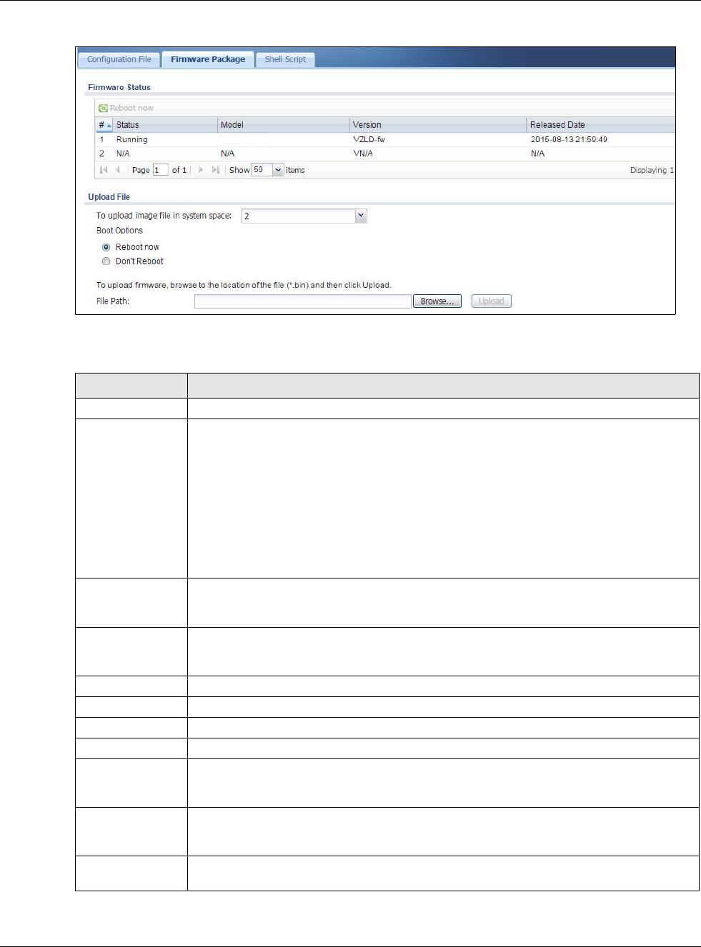
Chapter 32 File Manager
USG20(W)-VPN Series User’s Guide
611
Figure 430 Maintenance > File Manager > Firmware Package
The following table describes the labels in this screen.
Table 265 Maintenance > File Manager > Firmware Package
LABEL DESCRIPTION
Firmware Status
Reboot Now Click the Reboot Now button to restart the USG. If you applied changes in the Web
configurator, these were saved automatically and do not change when you reboot. If you
made changes in the CLI, however, you have to use the write command to save the
configuration before you reboot. Otherwise, the changes are lost when you reboot.
If you want the Standby firmware to be the Running firmware, then select the Standby
firmware row and click Reboot Now. Wait a few minutes until the login screen appears.
If the login screen does not appear, clear your browser cache and refresh the screen or
type the IP address of the USG in your Web browser again.
You can also use the CLI command reboot to restart the USG.
# This displays the system space (partition) index number where the firmwarm is located.
The firmware can be either Standby or Running; only one firmware can be running at
any one time.
Status This indicates whether the firmware is Running, or not running but already uploaded to
the USG and is on Standby. It displays N/A if there is no firmware uploaded to that
system space.
Model This is the model name of the device which the firmware is running on.
Version This is the firmware version and the date created.
Released Date This is the date that the version of the firmware was created.
Upload File
To upload image
file in system
space
Click the To upload image file in system space pull-down menu and select 1 or 2. The
default is the Standby system space, so if you want to upload new firmware to be the
Running firmware, then select the correct system space.
Boot Options If you upload firmware to the Running system space, the USG will reboot automatically.
If you upload firmware to the Standby system space, you have the option to Reboot
now or Don’t Reboot.
Reboot now If you select Reboot now, then the firmware upload to Standby system space will
become the Running firmware after you click Upload and the upload process completes.
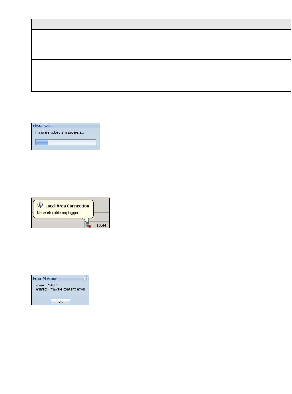
Chapter 32 File Manager
USG20(W)-VPN Series User’s Guide
612
After you see the Firmware Upload in Process screen, wait a few minutes before logging into the
USG again.
Figure 431 Firmware Upload In Process
Note: The USG automatically reboots after a successful upload.
The USG automatically restarts causing a temporary network disconnect. In some operating
systems, you may see the following icon on your desktop.
Figure 432 Network
After five minutes, log in again and check your new firmware version in the Dashboard screen.
If the upload was not successful, the following message appears in the status bar at the bottom of
the screen.
Figure 433 Firmware Upload Error
32.4 The Shell Script Screen
Use shell script files to have the USG use commands that you specify. Use a text editor to create the
shell script files. They must use a “.zysh” filename extension.
Click Maintenance > File Manager > Shell Script to open the Shell Script screen. Use the
Shell Script screen to store, name, download, upload and run shell script files. You can store
multiple shell script files on the USG at the same time.
Don’t Reboot If you choose Don’t Reboot, then the firmware upload to Standby system space will be
the Standby firmware after you click Upload and the upload process completes.
If you want the Standby firmware to be the Running firmware, then select the Standby
firmware row in Firmware Status and click Reboot Now.
File Path Type in the location of the file you want to upload in this field or click Browse ... to find it.
Browse... Click Browse... to find the .bin file you want to upload. Remember that you must
decompress compressed (.zip) files before you can upload them.
Upload Click Upload to begin the upload process. This process may take a few minutes.
Table 265 Maintenance > File Manager > Firmware Package (continued)
LABEL DESCRIPTION
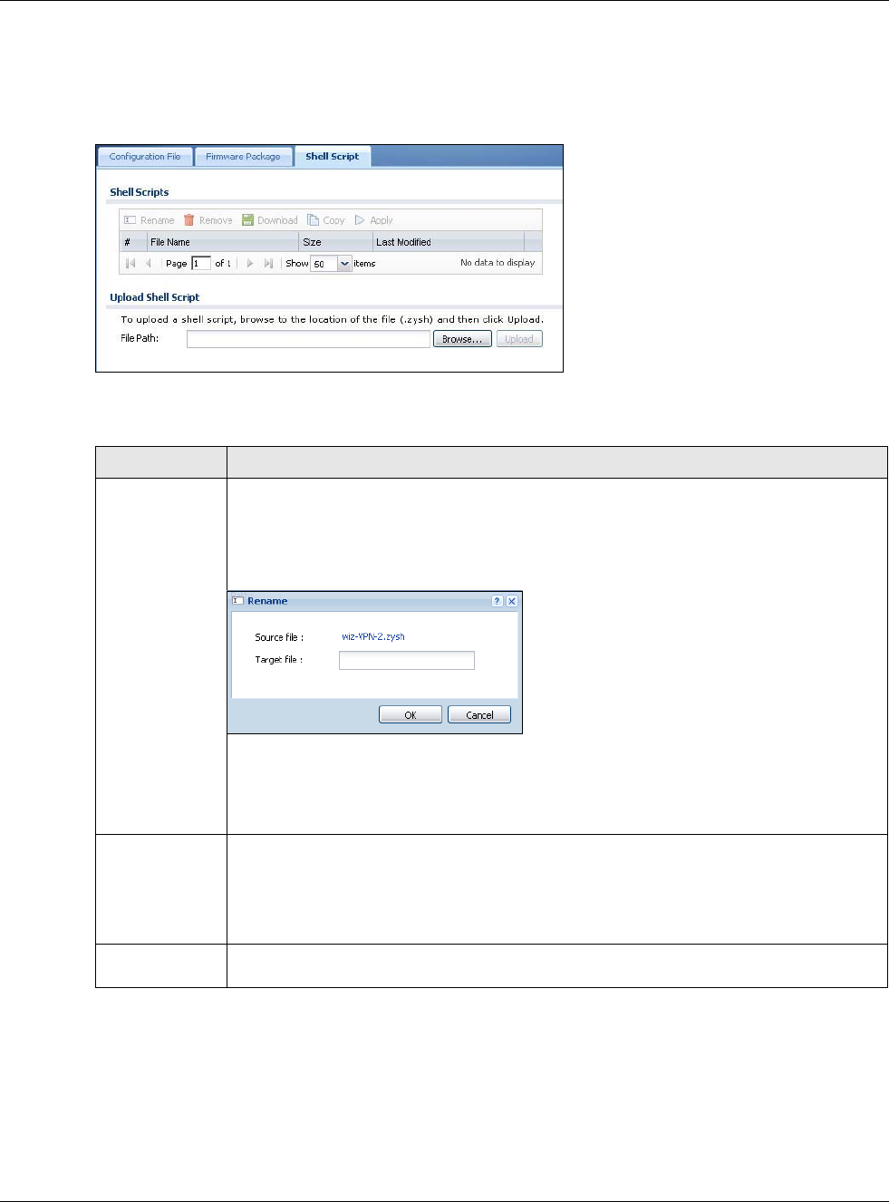
Chapter 32 File Manager
USG20(W)-VPN Series User’s Guide
613
Note: You should include write commands in your scripts. If you do not use the write
command, the changes will be lost when the USG restarts. You could use multiple
write commands in a long script.
Figure 434 Maintenance > File Manager > Shell Script
Each field is described in the following table.
Table 266 Maintenance > File Manager > Shell Script
LABEL DESCRIPTION
Rename Use this button to change the label of a shell script file on the USG.
You cannot rename a shell script to the name of another shell script in the USG.
Click a shell script’s row to select it and click Rename to open the Rename File screen.
Figure 435 Maintenance > File Manager > Shell Script > Rename
Specify the new name for the shell script file. Use up to 25 characters (including a-zA-Z0-
9;‘~!@#$%^&()_+[]{}’,.=-).
Click OK to save the duplicate or click Cancel to close the screen without saving a
duplicate of the configuration file.
Remove Click a shell script file’s row to select it and click Remove to delete the shell script file from
the USG.
A pop-up window asks you to confirm that you want to delete the shell script file. Click OK
to delete the shell script file or click Cancel to close the screen without deleting the shell
script file.
Download Click a shell script file’s row to select it and click Download to save the configuration to
your computer.
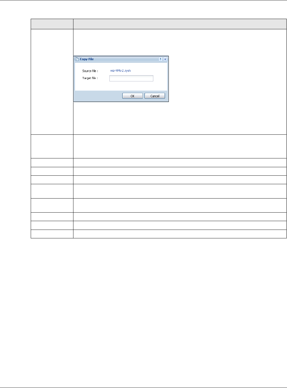
Chapter 32 File Manager
USG20(W)-VPN Series User’s Guide
614
Copy Use this button to save a duplicate of a shell script file on the USG.
Click a shell script file’s row to select it and click Copy to open the Copy File screen.
Figure 436 Maintenance > File Manager > Shell Script > Copy
Specify a name for the duplicate file. Use up to 25 characters (including a-zA-Z0-
9;‘~!@#$%^&()_+[]{}’,.=-).
Click OK to save the duplicate or click Cancel to close the screen without saving a
duplicate of the configuration file.
Apply Use this button to have the USG use a specific shell script file.
Click a shell script file’s row to select it and click Apply to have the USG use that shell
script file. You may need to wait awhile for the USG to finish applying the commands.
#This column displays the number for each shell script file entry.
File Name This column displays the label that identifies a shell script file.
Size This column displays the size (in KB) of a shell script file.
Last Modified This column displays the date and time that the individual shell script files were last
changed or saved.
Upload Shell
Script
The bottom part of the screen allows you to upload a new or previously saved shell script
file from your computer to your USG.
File Path Type in the location of the file you want to upload in this field or click Browse ... to find it.
Browse... Click Browse... to find the .zysh file you want to upload.
Upload Click Upload to begin the upload process. This process may take up to several minutes.
Table 266 Maintenance > File Manager > Shell Script (continued)
LABEL DESCRIPTION

USG20(W)-VPN Series User’s Guide
615
CHAPTER 33
Diagnostics
33.1 Overview
Use the diagnostics screens for troubleshooting.
33.1.1 What You Can Do in this Chapter
•Use the Diagnostics screen (see Section 33.2 on page 615) to generate a file containing the
USG’s configuration and diagnostic information if you need to provide it to customer support
during troubleshooting.
•Use the Packet Capture screens (see Section 33.3 on page 617) to capture packets going
through the USG.
•The Core Dump screens (Section 33.4 on page 620) save a process’s core dump to an attached
USB storage device if the process terminates abnormally (crashes) so you can send the file to
customer support for troubleshooting.
•The System Log screens (Section 33.5 on page 622) download files of system logs from a
connected USB storage device to your computer.
•Use the Network Tool screen (see Section 33.6 on page 622) to ping an IP address or trace the
route packets take to a host.
•Use the Wireless Frame Capture screens (see Section 33.7 on page 623) to capture network
traffic going through the AP interfaces connected to your USG.
33.2 The Diagnostic Screen
The Diagnostic screen provides an easy way for you to generate a file containing the USG’s
configuration and diagnostic information. You may need to send this file to customer support for
troubleshooting.
Click Maintenance > Diagnostics to open the Diagnostic screen.
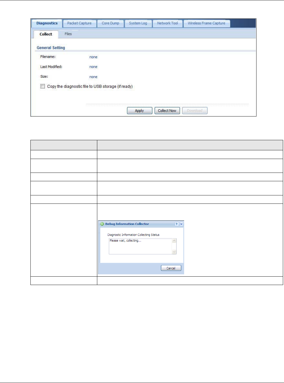
Chapter 33 Diagnostics
USG20(W)-VPN Series User’s Guide
616
Figure 437 Maintenance > Diagnostics
The following table describes the labels in this screen.
33.2.1 The Diagnostics Files Screen
Click Maintenance > Diagnostics > Files to open the diagnostic files screen. This screen lists the
files of diagnostic information the USG has collected and stored on the USG or a connected USB
storage device. You may need to send these files to customer support for troubleshooting.
Table 267 Maintenance > Diagnostics
LABEL DESCRIPTION
Filename This is the name of the most recently created diagnostic file.
Last modified This is the date and time that the last diagnostic file was created. The format is
yyyy-mm-dd hh:mm:ss.
Size This is the size of the most recently created diagnostic file.
Copy the diagnostic file to
USB storage (if ready)
Select this to have the USG create an extra copy of the diagnostic file to a
connected USB storage device.
Apply Click Apply to save your changes.
Collect Now Click this to have the USG create a new diagnostic file.
Wait while information is collected.
Download Click this to save the most recent diagnostic file to a computer.
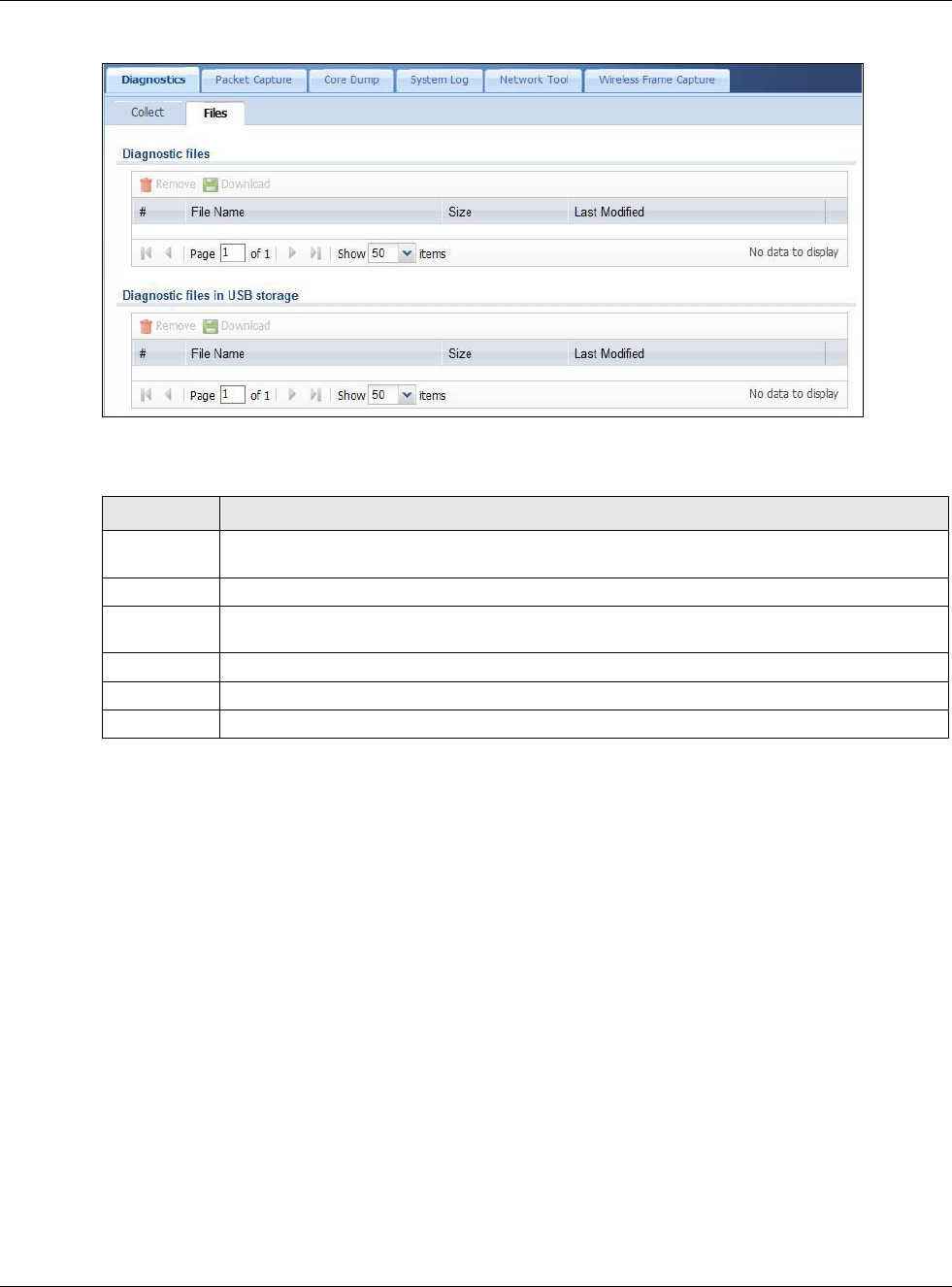
Chapter 33 Diagnostics
USG20(W)-VPN Series User’s Guide
617
Figure 438 Maintenance > Diagnostics > Files
The following table describes the labels in this screen.
33.3 The Packet Capture Screen
Use this screen to capture network traffic going through the USG’s interfaces. Studying these
packet captures may help you identify network problems. Click Maintenance > Diagnostics >
Packet Capture to open the packet capture screen.
Note: New capture files overwrite existing files of the same name. Change the File Suffix
field’s setting to avoid this.
Table 268 Maintenance > Diagnostics > Files
LABEL DESCRIPTION
Remove Select files and click Remove to delete them from the USG. Use the [Shift] and/or [Ctrl] key
to select multiple files. A pop-up window asks you to confirm that you want to delete.
Download Click a file to select it and click Download to save it to your computer.
#This column displays the number for each file entry. The total number of files that you can
save depends on the file sizes and the available storage space.
File Name This column displays the label that identifies the file.
Size This column displays the size (in bytes) of a file.
Last Modified This column displays the date and time that the individual files were saved.
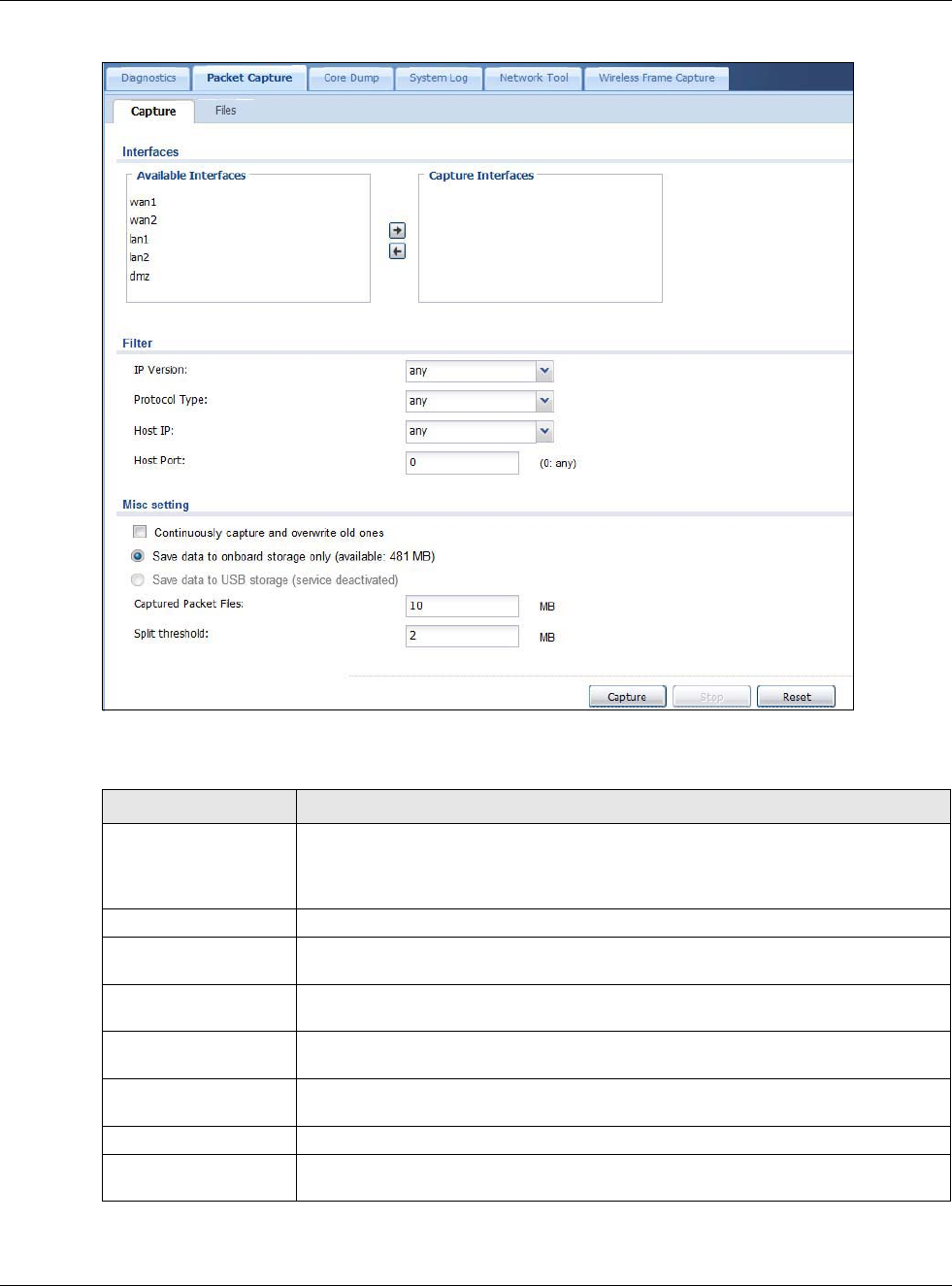
Chapter 33 Diagnostics
USG20(W)-VPN Series User’s Guide
618
Figure 439 Maintenance > Diagnostics > Packet Capture
The following table describes the labels in this screen.
Table 269 Maintenance > Diagnostics > Packet Capture
LABEL DESCRIPTION
Interfaces Enabled interfaces (except for virtual interfaces) appear under Available
Interfaces. Select interfaces for which to capture packets and click the right arrow
button to move them to the Capture Interfaces list. Use the [Shift] and/or [Ctrl]
key to select multiple objects.
Filter
IP Version Select the version of IP for which to capture packets. Select any to capture packets
for all IP versions.
Protocol Type Select the protocol of traffic for which to capture packets. Select any to capture
packets for all types of traffic.
Host IP Select a host IP address object for which to capture packets. Select any to capture
packets for all hosts. Select User Defined to be able to enter an IP address.
Host Port This field is configurable when you set the IP Type to any, tcp, or udp. Specify the
port number of traffic to capture.
Misc setting
Continuously capture
and overwrite old ones
Select this to have the USG keep capturing traffic and overwriting old packet capture
entries when the available storage space runs out.

Chapter 33 Diagnostics
USG20(W)-VPN Series User’s Guide
619
Save data to onboard
storage only
Select this to have the USG only store packet capture entries on the USG. The
available storage size is displayed as well.
Note: The USG reserves some onboard storage space as a buffer.
Save data to USB
storage
Select this to have the USG store packet capture entries only on a USB storage
device connected to the USG if the USG allows this.
Status:
Unused - the connected USB storage device was manually unmounted by using the
Remove Now button or for some reason the USG cannot mount it.
none - no USB storage device is connected.
service deactivated - USB storage feature is disabled (in Configuration >
Object > USB Storage), so the USG cannot use a connected USB device to store
system logs and other diagnostic information.
available - you can have the USG use the USB storage device. The available
storage capacity also displays.
Note: The USG reserves some USB storage space as a buffer.
Captured Packet Files When saving packet captures only to the USG’s onboard storage, specify a
maximum limit in megabytes for the total combined size of all the capture files on
the USG.
When saving packet captures to a connected USB storage device, specify a
maximum limit in megabytes for each capture file.
Note: If you have existing capture files and have not selected the Continuously
capture and overwrite old ones option, you may need to set this size larger
or delete existing capture files.
The valid range depends on the available onboard/USB storage size. The USG stops
the capture and generates the capture file when either the file reaches this size or
the time period specified in the Duration field expires.
Split threshold Specify a maximum size limit in megabytes for individual packet capture files. After
a packet capture file reaches this size, the USG starts another packet capture file.
Capture Click this button to have the USG capture packets according to the settings
configured in this screen.
You can configure the USG while a packet capture is in progress although you
cannot modify the packet capture settings.
The USG’s throughput or performance may be affected while a packet capture is in
progress.
After the USG finishes the capture it saves a separate capture file for each selected
interface. The total number of packet capture files that you can save depends on the
file sizes and the available flash storage space. Once the flash storage space is full,
adding more packet captures will fail.
Stop Click this button to stop a currently running packet capture and generate a separate
capture file for each selected interface.
Reset Click this button to return the screen to its last-saved settings.
Table 269 Maintenance > Diagnostics > Packet Capture (continued)
LABEL DESCRIPTION
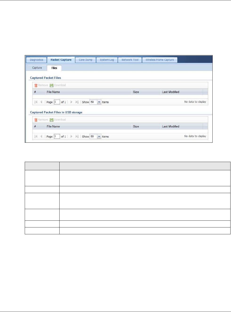
Chapter 33 Diagnostics
USG20(W)-VPN Series User’s Guide
620
33.3.1 The Packet Capture Files Screen
Click Maintenance > Diagnostics > Packet Capture > Files to open the packet capture files
screen. This screen lists the files of packet captures stored on the USG or a connected USB storage
device. You can download the files to your computer where you can study them using a packet
analyzer (also known as a network or protocol analyzer) such as Wireshark.
Figure 440 Maintenance > Diagnostics > Packet Capture > Files
The following table describes the labels in this screen.
33.4 The Core Dump Screen
Use the Core Dump screen to have the USG save a process’s core dump to an attached USB
storage device if the process terminates abnormally (crashes). You may need to send this file to
customer support for troubleshooting.
Click Maintenance > Diagnostics > Core Dump to open the following screen.
Table 270 Maintenance > Diagnostics > Packet Capture > Files
LABEL DESCRIPTION
Remove Select files and click Remove to delete them from the USG or the connected USB storage
device. Use the [Shift] and/or [Ctrl] key to select multiple files. A pop-up window asks you
to confirm that you want to delete.
Download Click a file to select it and click Download to save it to your computer.
#This column displays the number for each packet capture file entry. The total number of
packet capture files that you can save depends on the file sizes and the available flash
storage space.
File Name This column displays the label that identifies the file. The file name format is interface
name-file suffix.cap.
Size This column displays the size (in bytes) of a configuration file.
Last Modified This column displays the date and time that the individual files were saved.
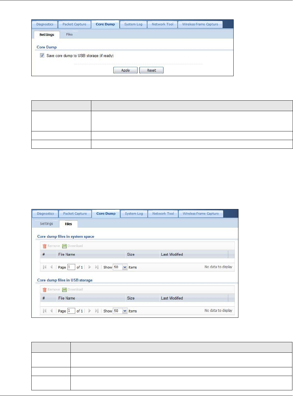
Chapter 33 Diagnostics
USG20(W)-VPN Series User’s Guide
621
Figure 441 Maintenance > Diagnostics > Core Dump
The following table describes the labels in this screen.
33.4.1 The Core Dump Files Screen
Click Maintenance > Diagnostics > Core Dump > Files to open the core dump files screen. This
screen lists the core dump files stored on the USG or a connected USB storage device. You may
need to send these files to customer support for troubleshooting.
Figure 442 Maintenance > Diagnostics > Core Dump > Files
The following table describes the labels in this screen.
Table 271 Maintenance > Diagnostics > Core Dump
LABEL DESCRIPTION
Save core dump to USB
storage (if ready)
Select this to have the USG save a process’s core dump to an attached USB storage
device if the process terminates abnormally (crashes). If you clear this option the
USG only saves
Apply Click Apply to save the changes.
Reset Click Reset to return the screen to its last-saved settings.
Table 272 Maintenance > Diagnostics > Core Dump > Files
LABEL DESCRIPTION
Remove Select files and click Remove to delete them from the USG. Use the [Shift] and/or [Ctrl] key
to select multiple files. A pop-up window asks you to confirm that you want to delete.
Download Click a file to select it and click Download to save it to your computer.
#This column displays the number for each core dump file entry. The total number of core
dump files that you can save depends on the file sizes and the available flash storage space.
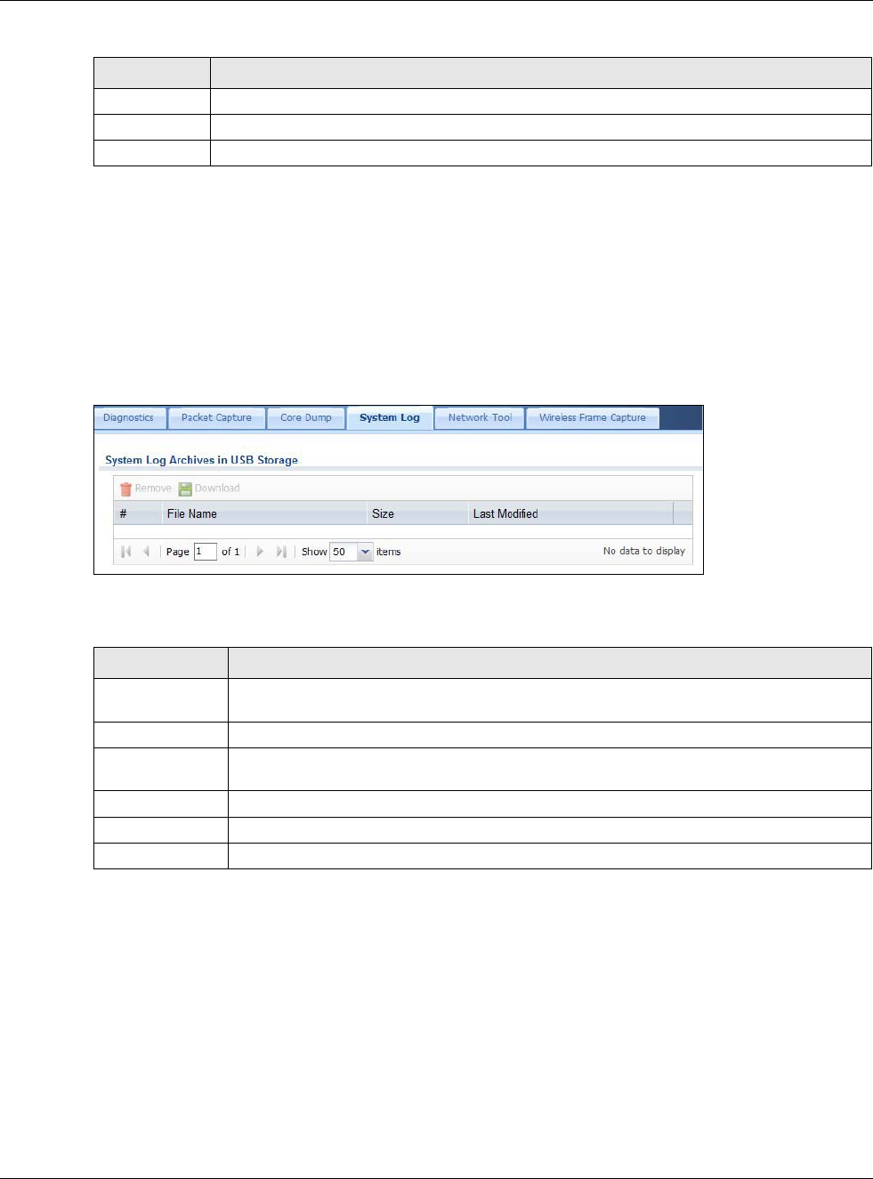
Chapter 33 Diagnostics
USG20(W)-VPN Series User’s Guide
622
33.5 The System Log Screen
Click Maintenance > Diagnostics > System Log to open the system log files screen. This screen
lists the files of system logs stored on a connected USB storage device. The files are in comma
separated value (csv) format. You can download them to your computer and open them in a tool
like Microsoft’s Excel.
Figure 443 Maintenance > Diagnostics > System Log
The following table describes the labels in this screen.
33.6 The Network Tool Screen
Use this screen to ping or traceroute an IP address.
Click Maintenance > Diagnostics > Network Tool to display this screen.
File Name This column displays the label that identifies the file.
Size This column displays the size (in bytes) of a file.
Last Modified This column displays the date and time that the individual files were saved.
Table 272 Maintenance > Diagnostics > Core Dump > Files (continued)
LABEL DESCRIPTION
Table 273 Maintenance > Diagnostics > System Log
LABEL DESCRIPTION
Remove Select files and click Remove to delete them from the USG. Use the [Shift] and/or [Ctrl]
key to select multiple files. A pop-up window asks you to confirm that you want to delete.
Download Click a file to select it and click Download to save it to your computer.
#This column displays the number for each file entry. The total number of files that you can
save depends on the file sizes and the available storage space.
File Name This column displays the label that identifies the file.
Size This column displays the size (in bytes) of a file.
Last Modified This column displays the date and time that the individual files were saved.
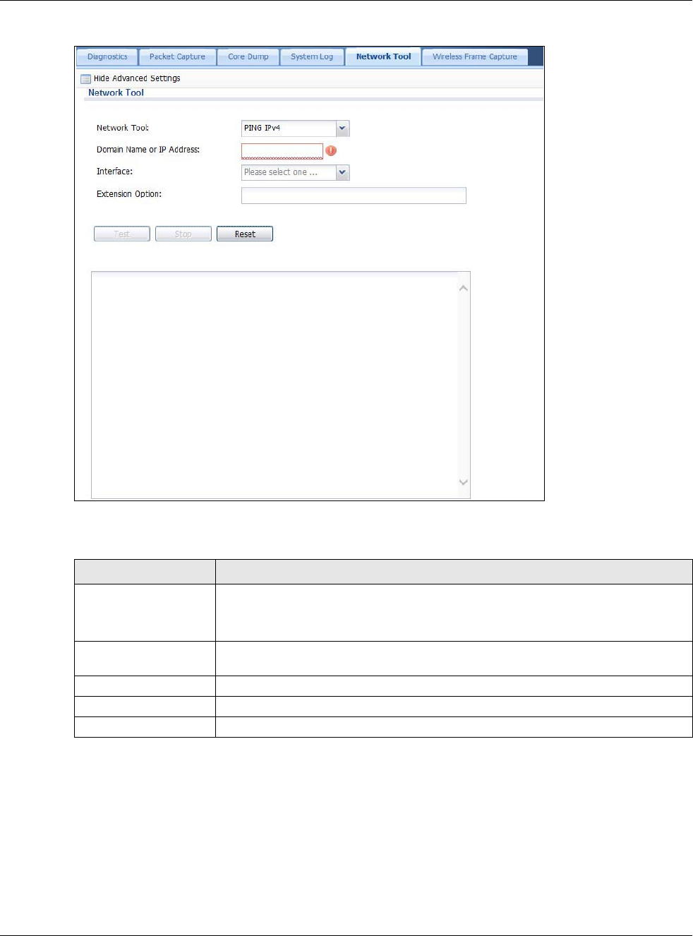
Chapter 33 Diagnostics
USG20(W)-VPN Series User’s Guide
623
Figure 444 Maintenance > Diagnostics > Network Tool
The following table describes the labels in this screen.
33.7 The Wireless Frame Capture Screen
Use this screen to capture wireless network traffic going through the AP interfaces connected to
your USG. Studying these frame captures may help you identify network problems.
Click Maintenance > Diagnostics > Wireless Frame Capture to display this screen.
Table 274 Maintenance > Diagnostics > Network Tool
LABEL DESCRIPTION
Network Tool Select PING IPv4 to ping the IP address that you entered.
Select TRACEROUTE IPv4 to perform the traceroute function. This determines the
path a packet takes to the specified computer.
Domain Name or IP
Address
Type the IPv4 address of a computer that you want to perform ping or traceroute in
order to test a connection.
Test Click this button to start to ping or run a traceroute.
Stop Click this button to terminate the current ping operation or traceroute.
Reset Click this button to return the screen to its last-saved settings.
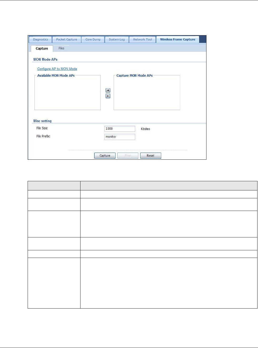
Chapter 33 Diagnostics
USG20(W)-VPN Series User’s Guide
624
Note: New capture files overwrite existing files of the same name. Change the File Prefix
field’s setting to avoid this.
Figure 445 Maintenance > Diagnostics > Wireless Frame Capture > Capture
The following table describes the labels in this screen.
Table 275 Maintenance > Diagnostics > Wireless Frame Capture > Capture
LABEL DESCRIPTION
MON Mode APs
Configure AP to
MON Mode Click this to go the Configuration > Wireless > AP Management screen, where
you can set one or more APs to monitor mode.
Available MON
Mode APs This column displays which APs on your wireless network are currently configured
for monitor mode.
Use the arrow buttons to move APs off this list and onto the Captured MON Mode
APs list.
Capture MON Mode
APs This column displays the monitor-mode configured APs selected to for wireless
frame capture.
Misc Setting
File Size Specify a maximum size limit in kilobytes for the total combined size of all the
capture files on the USG, including any existing capture files and any new capture
files you generate.
Note: If you have existing capture files you may need to set this size larger or delete
existing capture files.
The valid range is 1 to 50000. The USG stops the capture and generates the capture
file when either the file reaches this size.
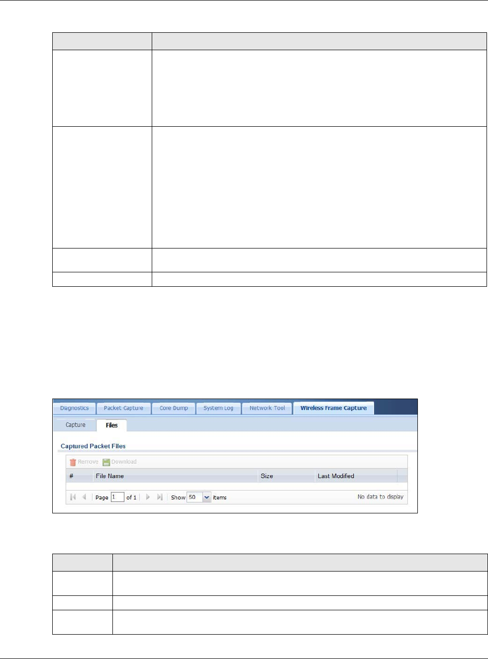
Chapter 33 Diagnostics
USG20(W)-VPN Series User’s Guide
625
33.7.1 The Wireless Frame Capture Files Screen
Click Maintenance > Diagnostics > Wireless Frame Capture > Files to open this screen. This
screen lists the files of wireless frame captures the USG has performed. You can download the files
to your computer where you can study them using a packet analyzer (also known as a network or
protocol analyzer) such as Wireshark.
Figure 446 Maintenance > Diagnostics > Wireless Frame Capture > Files
The following table describes the labels in this screen.
File Prefix Specify text to add to the front of the file name in order to help you identify frame
capture files.
You can modify the prefix to also create new frame capture files each time you
perform a frame capture operation. Doing this does no overwrite existing frame
capture files.
The file format is: [file prefix].cap. For example, “monitor.cap”.
Capture Click this button to have the USG capture frames according to the settings
configured in this screen.
You can configure the USG while a frame capture is in progress although you cannot
modify the frame capture settings.
The USG’s throughput or performance may be affected while a frame capture is in
progress.
After the USG finishes the capture it saves a combined capture file for all APs. The
total number of frame capture files that you can save depends on the file sizes and
the available flash storage space. Once the flash storage space is full, adding more
frame captures will fail.
Stop Click this button to stop a currently running frame capture and generate a combined
capture file for all APs.
Reset Click this button to return the screen to its last-saved settings.
Table 275 Maintenance > Diagnostics > Wireless Frame Capture > Capture (continued)
LABEL DESCRIPTION
Table 276 Maintenance > Diagnostics > Wireless Frame Capture > Files
LABEL DESCRIPTION
Remove Select files and click Remove to delete them from the USG. Use the [Shift] and/or [Ctrl] key
to select multiple files. A pop-up window asks you to confirm that you want to delete.
Download Click a file to select it and click Download to save it to your computer.
#This column displays the number for each packet capture file entry. The total number of packet
capture files that you can save depends on the file sizes and the available flash storage space.
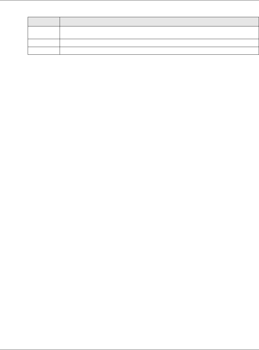
Chapter 33 Diagnostics
USG20(W)-VPN Series User’s Guide
626
File Name This column displays the label that identifies the file. The file name format is interface name-
file suffix.cap.
Size This column displays the size (in bytes) of a configuration file.
Last Modified This column displays the date and time that the individual files were saved.
Table 276 Maintenance > Diagnostics > Wireless Frame Capture > Files (continued)
LABEL DESCRIPTION

USG20(W)-VPN Series User’s Guide
627
CHAPTER 34
Packet Flow Explore
34.1 Overview
Use this to get a clear picture on how the USG determines where to forward a packet and how to
change the source IP address of the packet according to your current settings. This function
provides you a summary of all your routing and SNAT settings and helps troubleshoot any related
problems.
34.1.1 What You Can Do in this Chapter
•Use the Routing Status screen (see Section 34.2 on page 627) to view the overall routing flow
and each routing function’s settings.
•Use the SNAT Status screen (see Section 34.3 on page 632) to view the overall source IP
address conversion (SNAT) flow and each SNAT function’s settings.
34.2 The Routing Status Screen
The Routing Status screen allows you to view the current routing flow and quickly link to specific
routing settings. Click a function box in the Routing Flow section, the related routes (activated)
will display in the Routing Table section. To access this screen, click Maintenance > Packet
Flow Explore.
The order of the routing flow may vary depending on whether you:
•Select use policy route to override direct route in the CONFIGURATION > Network >
Routing > Policy Route screen.
• Use policy routes to control 1-1 NAT by using the policy control-virtual-server-rules
activate command.
•Select use policy routes to control dynamic IPSec rules in the CONFIGURATION > VPN >
IPSec VPN > VPN Connection screen.
Note: Once a packet matches the criteria of a routing rule, the USG takes the
corresponding action and does not perform any further flow checking.
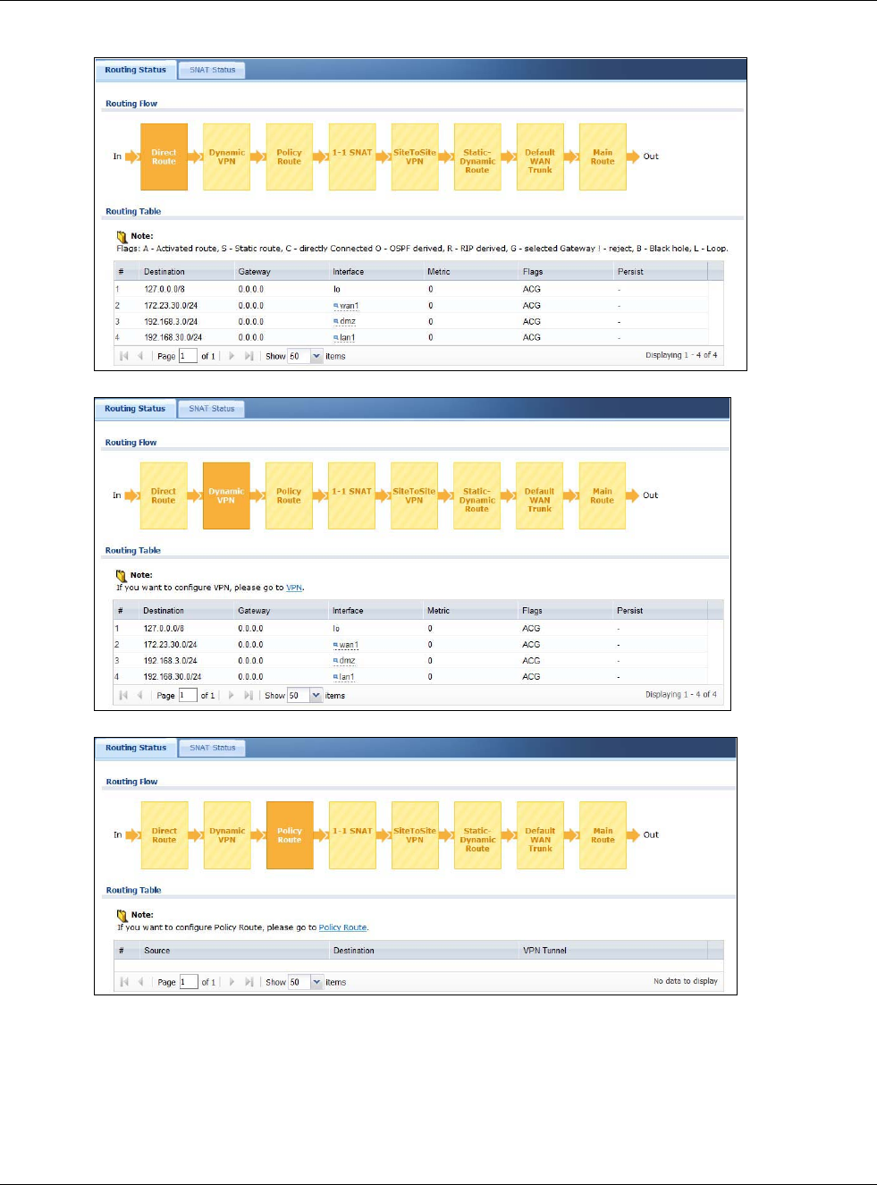
Chapter 34 Packet Flow Explore
USG20(W)-VPN Series User’s Guide
628
Figure 447 Maintenance > Packet Flow Explore > Routing Status (Direct Route)
Figure 448 Maintenance > Packet Flow Explore > Dynamic VPN
Figure 449 Maintenance > Packet Flow Explore > Routing Status (Policy Route)
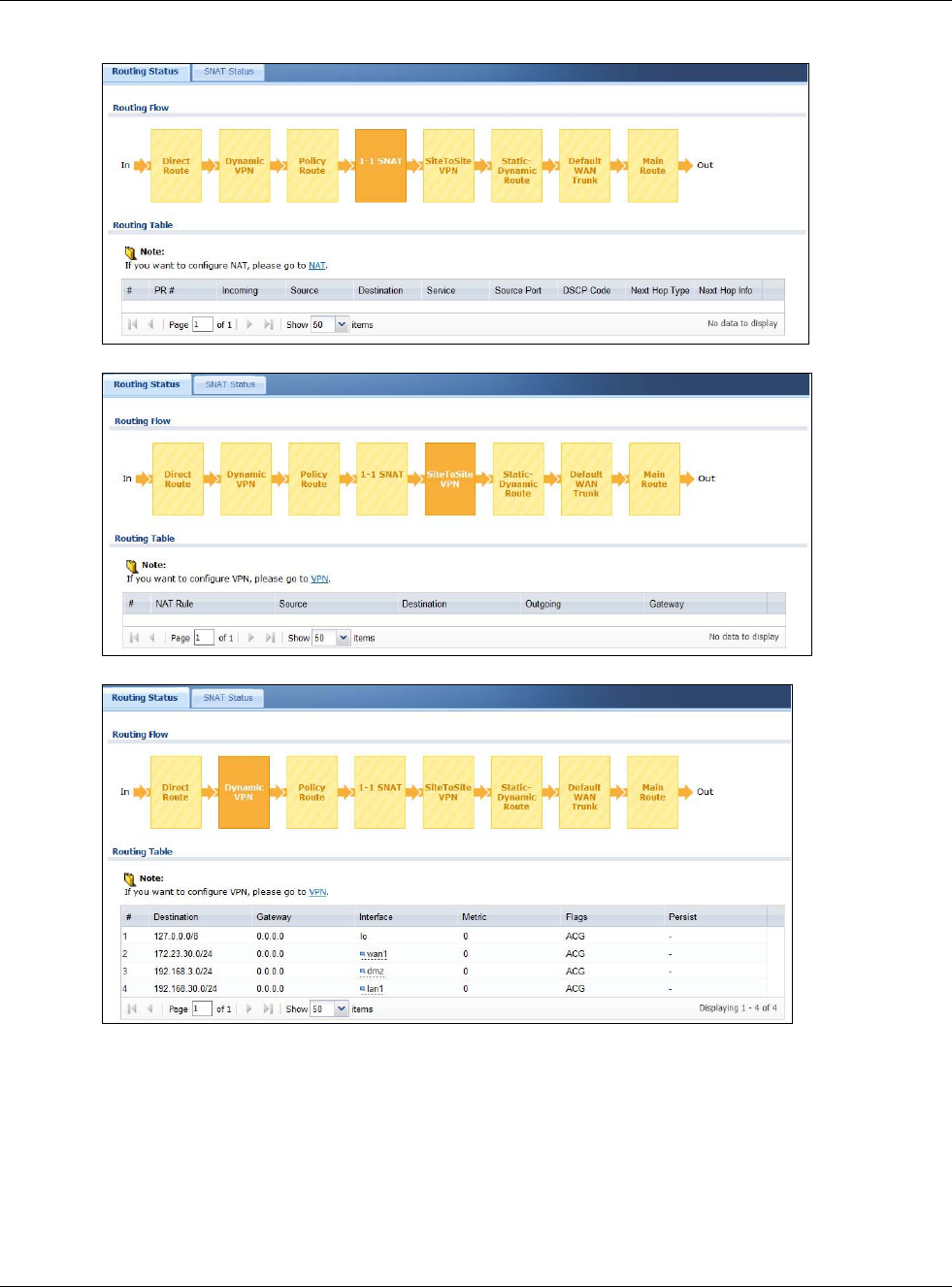
Chapter 34 Packet Flow Explore
USG20(W)-VPN Series User’s Guide
629
Figure 450 Maintenance > Packet Flow Explore > Routing Status (1-1 SNAT)
Figure 451 Maintenance > Packet Flow Explore > Routing Status (SiteToSite VPN)
Figure 452 Maintenance > Packet Flow Explore > Routing Status (Dynamic VPN)
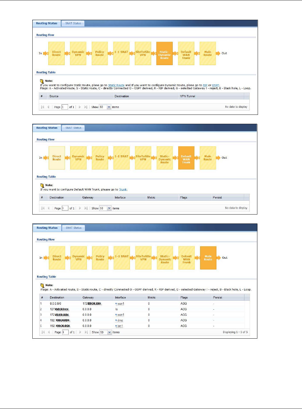
Chapter 34 Packet Flow Explore
USG20(W)-VPN Series User’s Guide
630
Figure 453 Maintenance > Packet Flow Explore > Routing Status (Static-Dynamic Route)
Figure 454 Maintenance > Packet Flow Explore > Routing Status (Default WAN Trunk)
Figure 455 Maintenance > Packet Flow Explore > Routing Status (Main Route)
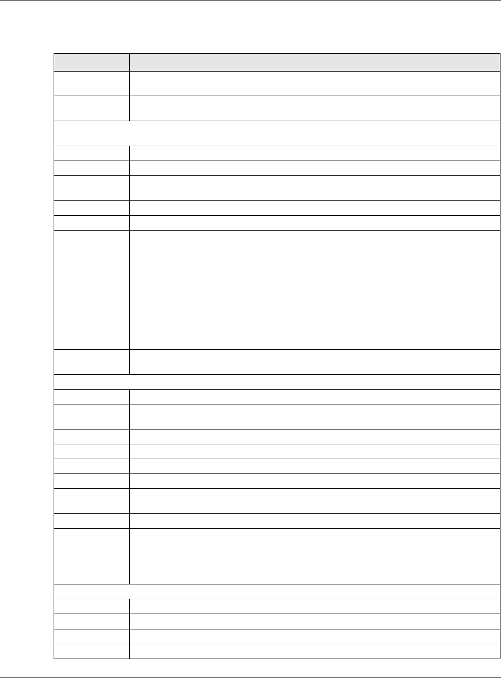
Chapter 34 Packet Flow Explore
USG20(W)-VPN Series User’s Guide
631
The following table describes the labels in this screen.
Table 277 Maintenance > Packet Flow Explore > Routing Status
LABEL DESCRIPTION
Routing Flow This section shows you the flow of how the USG determines where to route a packet. Click
a function box to display the related settings in the Routing Table section.
Routing Table This section shows the corresponding settings according to the function box you click in the
Routing Flow section.
The following fields are available if you click Direct Route, Static-Dynamic Route, or Main Route in the
Routing Flow section.
#This field is a sequential value, and it is not associated with any entry.
Destination This is the destination IP address of a route.
Gateway This is the IP address of the next-hop gateway or the interface through which the traffic is
routed.
Interface This is the name of an interface associated with the route.
Metric This is the route’s priority among the displayed routes.
Flags This indicates additional information for the route. The possible flags are:
•A - this route is currently activated
•S - this is a static route
•C - this is a direct connected route
•O - this is a dynamic route learned through OSPF
•R - this is a dynamic route learned through RIP
•G - the route is to a gateway (router) in the same network.
•! - this is a route which forces a route lookup to fail.
•B - this is a route which discards packets.
•L - this is a recursive route.
Persist This is the remaining time of a dynamically learned route. The USG removes the route
after this time period is counted down to zero.
The following fields are available if you click Policy Route in the Routing Flow section.
#This field is a sequential value, and it is not associated with any entry.
PR # This is the number of an activated policy route. If you have configured a schedule for the
route, this screen only displays the route at the scheduled time.
Incoming This is the interface on which the packets are received.
Source This is the source IP address(es) from which the packets are sent.
Destination This is the destination IP address(es) to which the packets are transmitted.
Service This is the name of the service object. any means all services.
DSCP Code This is the DSCP value of incoming packets to which this policy route applies. See Section
10.2 on page 228 for more information.
Next Hop Type This is the type of the next hop to which packets are directed.
Next Hop Info • This is the main route if the next hop type is Auto.
• This is the interface name and gateway IP address if the next hop type is Interface /
GW.
• This is the tunnel name if the next hop type is VPN Tunnel.
• This is the trunk name if the next hop type is Trunk.
The following fields are available if you click 1-1 SNAT in the Routing Flow section.
#This field is a sequential value, and it is not associated with any entry.
NAT Rule This is the name of an activated 1:1 or Many 1:1 NAT rule in the NAT table.
Source This is the original source IP address(es). any means any IP address.
Destination This is the original destination IP address(es). any means any IP address.
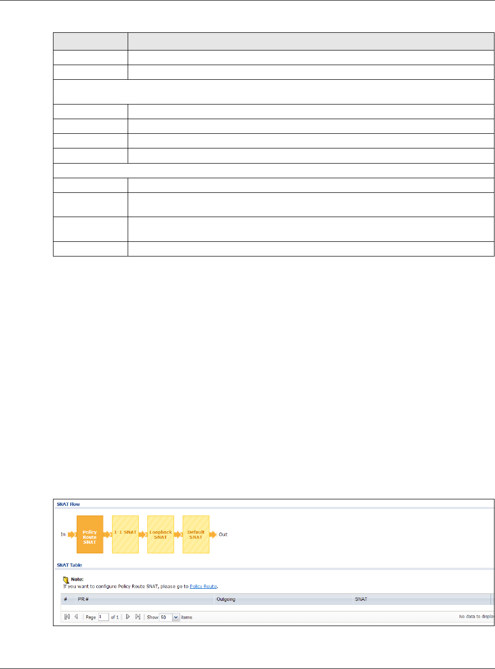
Chapter 34 Packet Flow Explore
USG20(W)-VPN Series User’s Guide
632
34.3 The SNAT Status Screen
The SNAT Status screen allows you to view and quickly link to specific source NAT (SNAT) settings.
Click a function box in the SNAT Flow section, the related SNAT rules (activated) will display in the
SNAT Table section. To access this screen, click Maintenance > Packet Flow Explore > SNAT
Status.
The order of the SNAT flow may vary depending on whether you:
• select use default SNAT in the CONFIGURATION > Network > Interface > Trunk screen.
• use policy routes to control 1-1 NAT by using the policy control-virtual-server-rules
activate command.
Note: Once a packet matches the criteria of an SNAT rule, the USG takes the
corresponding action and does not perform any further flow checking.
Figure 456 Maintenance > Packet Flow Explore > SNAT Status (Policy Route SNAT)
Outgoing This is the name of an interface which transmits packets out of the USG.
Gateway This is the IP address of the gateway in the same network of the outgoing interface.
The following fields are available if you click Dynamic VPN or SiteToSite VPN in the Routing Flow
section.
#This field is a sequential value, and it is not associated with any entry.
Source This is the IP address(es) of the local VPN network.
Destination This is the IP address(es) for the remote VPN network.
VPN Tunnel This is the name of the VPN tunnel.
The following fields are available if you click Default WAN Trunk in the Routing Flow section.
#This field is a sequential value, and it is not associated with any entry.
Source This is the source IP address(es) from which the packets are sent. any means any IP
address.
Destination This is the destination IP address(es) to which the packets are transmitted. any means
any IP address.
Trunk This is the name of the WAN trunk through which the matched packets are transmitted.
Table 277 Maintenance > Packet Flow Explore > Routing Status (continued)
LABEL DESCRIPTION
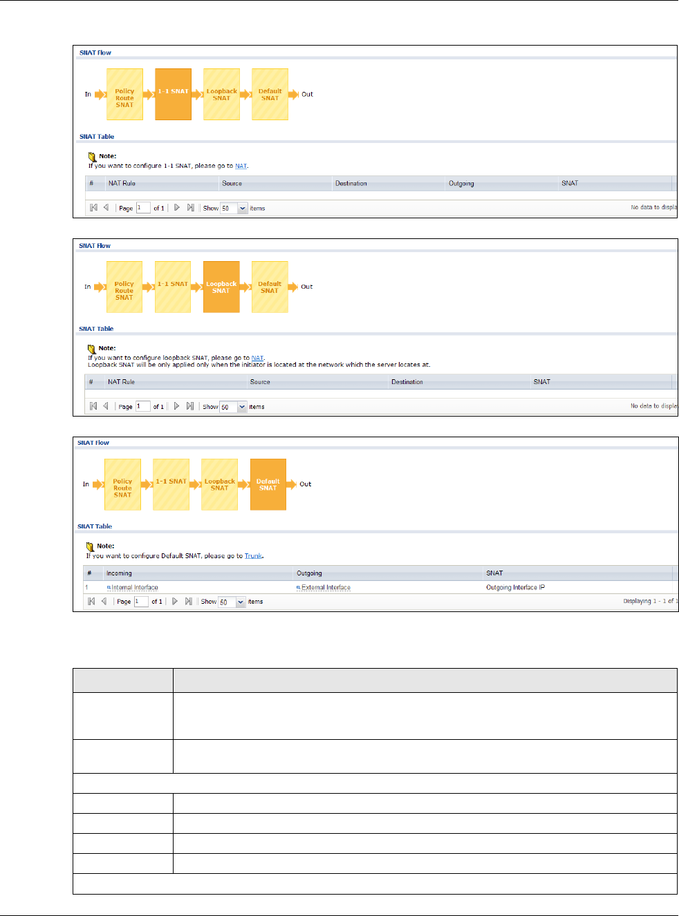
Chapter 34 Packet Flow Explore
USG20(W)-VPN Series User’s Guide
633
Figure 457 Maintenance > Packet Flow Explore > SNAT Status (1-1 SNAT)
Figure 458 Maintenance > Packet Flow Explore > SNAT Status (Loopback SNAT)
Figure 459 Maintenance > Packet Flow Explore > SNAT Status (Default SNAT)
The following table describes the labels in this screen.
Table 278 Maintenance > Packet Flow Explore > SNAT Status
LABEL DESCRIPTION
SNAT Flow This section shows you the flow of how the USG changes the source IP address for a packet
according to the rules you have configured in the USG. Click a function box to display the
related settings in the SNAT Table section.
SNAT Table The table fields in this section vary depending on the function box you select in the SNAT
Flow section.
The following fields are available if you click Policy Route SNAT in the SNAT Flow section.
#This field is a sequential value, and it is not associated with any entry.
PR # This is the number of an activated policy route which uses SNAT.
Outgoing This is the outgoing interface that the route uses to transmit packets.
SNAT This is the source IP address(es) that the SNAT rule uses finally.
The following fields are available if you click 1-1 SNAT in the SNAT Flow section.
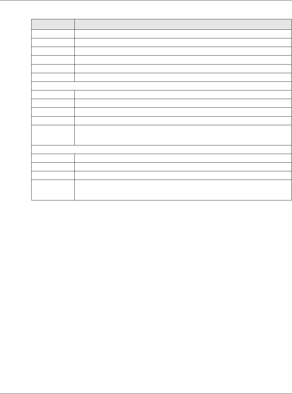
Chapter 34 Packet Flow Explore
USG20(W)-VPN Series User’s Guide
634
#This field is a sequential value, and it is not associated with any entry.
NAT Rule This is the name of an activated NAT rule which uses SNAT.
Source This is the original source IP address(es).
Destination This is the original destination IP address(es).
Outgoing This is the outgoing interface that the SNAT rule uses to transmit packets.
SNAT This is the source IP address(es) that the SNAT rule uses finally.
The following fields are available if you click Loopback SNAT in the SNAT Flow section.
#This field is a sequential value, and it is not associated with any entry.
NAT Rule This is the name of an activated NAT rule which uses SNAT and enables NAT loopback.
Source This is the original source IP address(es). any means any IP address.
Destination This is the original destination IP address(es). any means any IP address.
SNAT This indicates which source IP address the SNAT rule uses finally. For example, Outgoing
Interface IP means that the USG uses the IP address of the outgoing interface as the
source IP address for the matched packets it sends out through this rule.
The following fields are available if you click Default SNAT in the SNAT Flow section.
#This field is a sequential value, and it is not associated with any entry.
Incoming This indicates internal interface(s) on which the packets are received.
Outgoing This indicates external interface(s) from which the packets are transmitted.
SNAT This indicates which source IP address the SNAT rule uses finally. For example, Outgoing
Interface IP means that the USG uses the IP address of the outgoing interface as the
source IP address for the matched packets it sends out through this rule.
Table 278 Maintenance > Packet Flow Explore > SNAT Status (continued)
LABEL DESCRIPTION
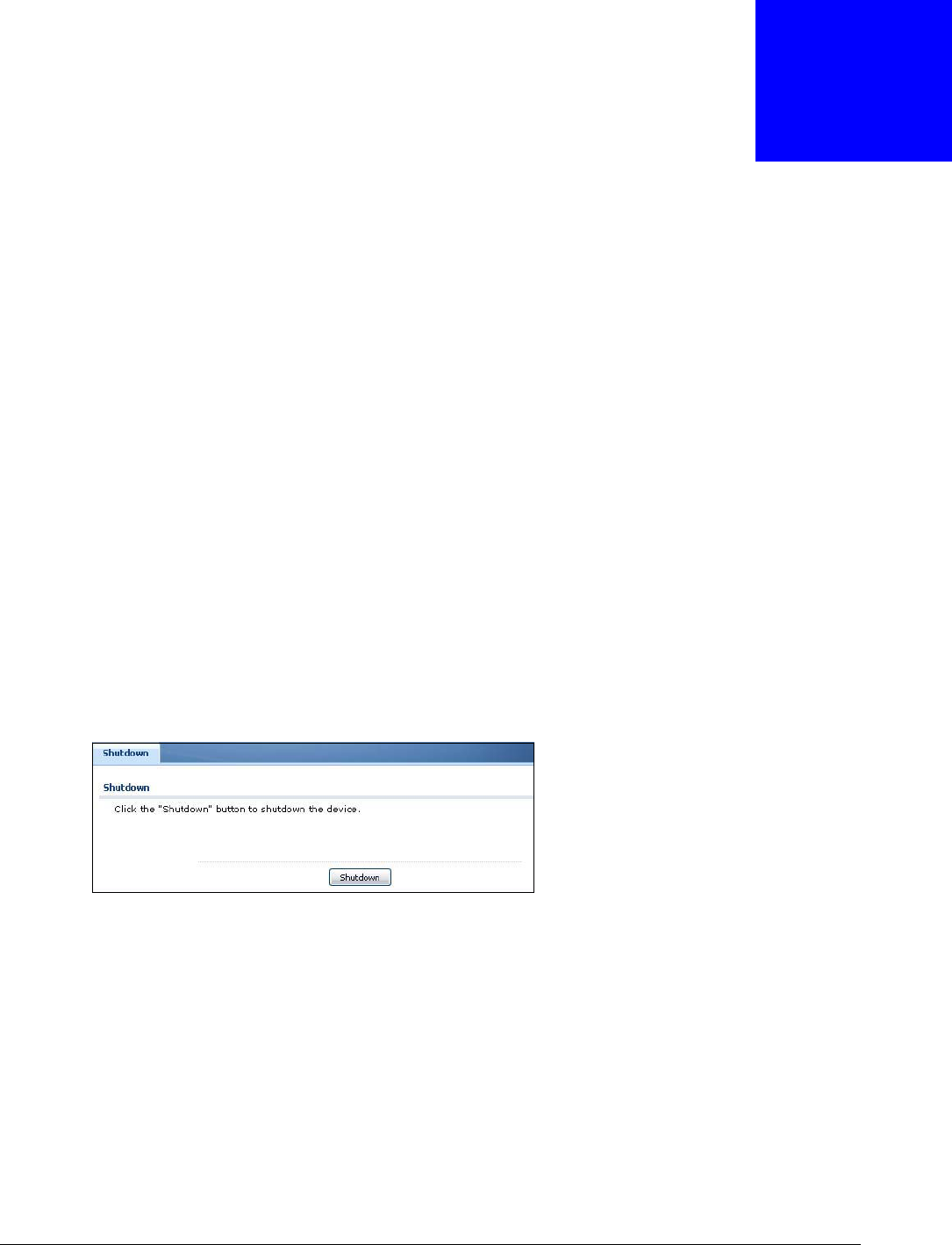
USG20(W)-VPN Series User’s Guide
635
CHAPTER 35
Shutdown
35.1 Overview
Use this to shutdown the device in preparation for disconnecting the power.
Always use the Maintenance > Shutdown > Shutdown screen or the
“shutdown” command before you turn off the USG or remove the power.
Not doing so can cause the firmware to become corrupt.
35.1.1 What You Need To Know
Shutdown writes all cached data to the local storage and stops the system processes.
35.2 The Shutdown Screen
To access this screen, click Maintenance > Shutdown.
Figure 460 Maintenance > Shutdown
Click the Shutdown button to shut down the USG. Wait for the device to shut down before you
manually turn off or remove the power. It does not turn off the power.
You can also use the CLI command shutdown to shutdown the USG.

USG20(W)-VPN Series User’s Guide
636
CHAPTER 36
Troubleshooting
This chapter offers some suggestions to solve problems you might encounter.
• You can also refer to the logs (see Chapter 6 on page 100).
• For the order in which the USG applies its features and checks, see Chapter 34 on page 627.
None of the LEDs turn on.
Make sure that you have the power cord connected to the USG and plugged in to an appropriate
power source. Make sure you have the USG turned on. Check all cable connections.
If the LEDs still do not turn on, you may have a hardware problem. In this case, you should contact
your local vendor.
Cannot access the USG from the LAN.
• Check the cable connection between the USG and your computer or switch.
• Ping the USG from a LAN computer. Make sure your computer’s Ethernet card is installed and
functioning properly. Also make sure that its IP address is in the same subnet as the USG’s.
• In the computer, click Start, (All) Programs, Accessories and then Command Prompt. In
the Command Prompt window, type "ping" followed by the USG’s LAN IP address (192.168.1.1
is the default) and then press [ENTER]. The USG should reply.
• If you’ve forgotten the USG’s password, use the RESET button. Press the button in for about 5
seconds (or until the PWR LED starts to blink), then release it. It returns the USG to the factory
defaults (password is 1234, LAN IP address 192.168.1.1 etc.; see your User’s Guide for details).
• If you’ve forgotten the USG’s IP address, you can use the commands through the console port to
check it. Connect your computer to the CONSOLE port using a console cable. Your computer
should have a terminal emulation communications program (such as HyperTerminal) set to
VT100 terminal emulation, no parity, 8 data bits, 1 stop bit, no flow control and 115200 bps port
speed.
I cannot access the Internet.
• Check the USG’s connection to the Ethernet jack with Internet access. Make sure the Internet
gateway device (such as a DSL modem) is working properly.
• Check the WAN interface's status in the Dashboard. Use the installation setup wizard again and
make sure that you enter the correct settings. Use the same case as provided by your ISP.
Chapter 36 Troubleshooting
USG20(W)-VPN Series User’s Guide
637
The content filter category service is not working.
• Make sure your USG has the content filter category service registered and that the license is not
expired. Purchase a new license if the license is expired.
• Make sure your USG is connected to the Internet.
I configured security settings but the USG is not applying them for certain interfaces.
Many security settings are usually applied to zones. Make sure you assign the interfaces to the
appropriate zones. When you create an interface, there is no security applied on it until you assign
it to a zone.
The USG is not applying the custom policy route I configured.
The USG checks the policy routes in the order that they are listed. So make sure that your custom
policy route comes before any other routes that the traffic would also match.
The USG is not applying the custom security policy I configured.
The USG checks the security policies in the order that they are listed. So make sure that your
custom security policy comes before any other rules that the traffic would also match.
I cannot enter the interface name I want.
The format of interface names other than the Ethernet interface names is very strict. Each name
consists of 2-4 letters (interface type), followed by a number (x, limited by the maximum number
of each type of interface). For example, VLAN interfaces are vlan0, vlan1, vlan2, ...; and so on.
• The names of virtual interfaces are derived from the interfaces on which they are created. For
example, virtual interfaces created on Ethernet interface wan1 are called wan1:1, wan1:2, and
so on. Virtual interfaces created on VLAN interface vlan2 are called vlan2:1, vlan2:2, and so on.
You cannot specify the number after the colon(:) in the Web Configurator; it is a sequential
number. You can specify the number after the colon if you use the CLI to set up a virtual
interface.
I cannot set up a PPP interface, virtual Ethernet interface or virtual VLAN interface on an
Ethernet interface.
Chapter 36 Troubleshooting
USG20(W)-VPN Series User’s Guide
638
You cannot set up a PPP interface, virtual Ethernet interface or virtual VLAN interface if the
underlying interface is a member of a bridge. You also cannot add an Ethernet interface or VLAN
interface to a bridge if the member interface has a virtual interface or PPP interface on top of it.
My rules and settings that apply to a particular interface no longer work.
The interface’s IP address may have changed. To avoid this create an IP address object based on
the interface. This way the USG automatically updates every rule or setting that uses the object
whenever the interface’s IP address settings change. For example, if you change LAN1’s IP address,
the USG automatically updates the corresponding interface-based, LAN1 subnet address object.
I cannot set up a PPP interface.
You have to set up an ISP account before you create a PPPoE or PPTP interface.
The data rates through my cellular connection are no-where near the rates I expected.
The actual cellular data rate you obtain varies depending on the cellular device you use, the signal
strength to the service provider’s base station, and so on.
I created a cellular interface but cannot connect through it.
• Make sure you have a compatible mobile broadband device installed or connected. See
www.zyxel.com for details.
• Make sure you have the cellular interface enabled.
• Make sure the cellular interface has the correct user name, password, and PIN code configured
with the correct casing.
• If the USG has multiple WAN interfaces, make sure their IP addresses are on different subnets.
Hackers have accessed my WEP-encrypted wireless LAN.
WEP is extremely insecure. Its encryption can be broken by an attacker, using widely-available
software. It is strongly recommended that you use a more effective security mechanism. Use the
strongest security mechanism that all the wireless devices in your network support. WPA2 or WPA2-
PSK is recommended.
Chapter 36 Troubleshooting
USG20(W)-VPN Series User’s Guide
639
The wireless security is not following the re-authentication timer setting I specified.
If a RADIUS server authenticates wireless stations, the re-authentication timer on the RADIUS
server has priority. Change the RADIUS server’s configuration if you need to use a different re-
authentication timer setting.
I cannot configure a particular VLAN interface on top of an Ethernet interface even though I
have it configured it on top of another Ethernet interface.
Each VLAN interface is created on top of only one Ethernet interface.
The USG is not applying an interface’s configured ingress bandwidth limit.
At the time of writing, the USG does not support ingress bandwidth management.
The USG routes and applies SNAT for traffic from some interfaces but not from others.
The USG automatically uses SNAT for traffic it routes from internal interfaces to external interfaces.
For example LAN to WAN traffic. You must manually configure a policy route to add routing and
SNAT settings for an interface with the Interface Type set to General. You can also configure a
policy route to override the default routing and SNAT behavior for an interface with the Interface
Type set to Internal or External.
I cannot get Dynamic DNS to work.
• You must have a public WAN IP address to use Dynamic DNS.
• Make sure you recorded your DDNS account’s user name, password, and domain name and have
entered them properly in the USG.
• You may need to configure the DDNS entry’s IP Address setting to Auto if the interface has a
dynamic IP address or there are one or more NAT routers between the USG and the DDNS server.
• The USG may not determine the proper IP address if there is an HTTP proxy server between the
USG and the DDNS server.
I cannot create a second HTTP redirect rule for an incoming interface.
You can configure up to one HTTP redirect rule for each (incoming) interface.
Chapter 36 Troubleshooting
USG20(W)-VPN Series User’s Guide
640
The USG keeps resetting the connection.
If an alternate gateway on the LAN has an IP address in the same subnet as the USG’s LAN IP
address, return traffic may not go through the USG. This is called an asymmetrical or “triangle”
route. This causes the USG to reset the connection, as the connection has not been acknowledged.
You can set the USG’s security policy to permit the use of asymmetrical route topology on the
network (so it does not reset the connection) although this is not recommended since allowing
asymmetrical routes may let traffic from the WAN go directly to the LAN without passing through
the USG. A better solution is to use virtual interfaces to put the USG and the backup gateway on
separate subnets. See Asymmetrical Routes on page 320 and the chapter about interfaces for more
information.
I cannot set up an IPSec VPN tunnel to another device.
If the IPSec tunnel does not build properly, the problem is likely a configuration error at one of the
IPSec routers. Log into both ZyXEL IPSec routers and check the settings in each field methodically
and slowly. Make sure both the USG and remote IPSec router have the same security settings for
the VPN tunnel. It may help to display the settings for both routers side-by-side.
Here are some general suggestions. See also Chapter 21 on page 332.
• The system log can often help to identify a configuration problem.
• If you enable NAT traversal, the remote IPSec device must also have NAT traversal enabled.
• The USG and remote IPSec router must use the same authentication method to establish the IKE
SA.
• Both routers must use the same negotiation mode.
• Both routers must use the same encryption algorithm, authentication algorithm, and DH key
group.
• When using pre-shared keys, the USG and the remote IPSec router must use the same pre-
shared key.
• The USG’s local and peer ID type and content must match the remote IPSec router’s peer and
local ID type and content, respectively.
• The USG and remote IPSec router must use the same active protocol.
• The USG and remote IPSec router must use the same encapsulation.
• The USG and remote IPSec router must use the same SPI.
• If the sites are/were previously connected using a leased line or ISDN router, physically
disconnect these devices from the network before testing your new VPN connection. The old
route may have been learnt by RIP and would take priority over the new VPN connection.
• To test whether or not a tunnel is working, ping from a computer at one site to a computer at the
other.
Before doing so, ensure that both computers have Internet access (via the IPSec routers).
• It is also helpful to have a way to look at the packets that are being sent and received by the USG
and remote IPSec router (for example, by using a packet sniffer).
Chapter 36 Troubleshooting
USG20(W)-VPN Series User’s Guide
641
Check the configuration for the following USG features.
• The USG does not put IPSec SAs in the routing table. You must create a policy route for each VPN
tunnel. See Chapter 10 on page 226.
•Make sure the To-USG security policies allow IPSec VPN traffic to the USG. IKE uses UDP port
500, AH uses IP protocol 51, and ESP uses IP protocol 50.
• The USG supports UDP port 500 and UDP port 4500 for NAT traversal. If you enable this, make
sure the To-USG security policies allow UDP port 4500 too.
• Make sure regular security policies allow traffic between the VPN tunnel and the rest of the
network. Regular security policies check packets the USG sends before the USG encrypts them
and check packets the USG receives after the USG decrypts them. This depends on the zone to
which you assign the VPN tunnel and the zone from which and to which traffic may be routed.
• If you set up a VPN tunnel across the Internet, make sure your ISP supports AH or ESP
(whichever you are using).
• If you have the USG and remote IPSec router use certificates to authenticate each other, You
must set up the certificates for the USG and remote IPSec router first and make sure they trust
each other’s certificates. If the USG’s certificate is self-signed, import it into the remote IPsec
router. If it is signed by a CA, make sure the remote IPsec router trusts that CA. The USG uses
one of its Trusted Certificates to authenticate the remote IPSec router’s certificate. The trusted
certificate can be the remote IPSec router’s self-signed certificate or that of a trusted CA that
signed the remote IPSec router’s certificate.
• Multiple SAs connecting through a secure gateway must have the same negotiation mode.
The VPN connection is up but VPN traffic cannot be transmitted through the VPN tunnel.
If you have the Configuration > VPN > IPSec VPN > VPN Connection screen’s Use Policy
Route to control dynamic IPSec rules option enabled, check the routing policies to see if they
are sending traffic elsewhere instead of through the VPN tunnels.
I uploaded a logo to show in the SSL VPN user screens but it does not display properly.
The logo graphic must be GIF, JPG, or PNG format. The graphic should use a resolution of 103 x 29
pixels to avoid distortion when displayed. The USG automatically resizes a graphic of a different
resolution to 103 x 29 pixels. The file size must be 100 kilobytes or less. Transparent background is
recommended.
I logged into the SSL VPN but cannot see some of the resource links.
Available resource links vary depending on the SSL application object’s configuration.
I changed the LAN IP address and can no longer access the Internet.
Chapter 36 Troubleshooting
USG20(W)-VPN Series User’s Guide
642
The USG automatically updates address objects based on an interface’s IP address, subnet, or
gateway if the interface’s IP address settings change. However, you need to manually edit any
address objects for your LAN that are not based on the interface.
I cannot get the RADIUS server to authenticate the USG‘s default admin account.
The default admin account is always authenticated locally, regardless of the authentication method
setting.
The USG fails to authentication the ext-user user accounts I configured.
An external server such as AD, LDAP or RADIUS must authenticate the ext-user accounts. If the
USG tries to use the local database to authenticate an ext-user, the authentication attempt will
always fail. (This is related to AAA servers and authentication methods, which are discussed in
other chapters in this guide.)
I cannot add the admin users to a user group with access users.
You cannot put access users and admin users in the same user group.
I cannot add the default admin account to a user group.
You cannot put the default admin account into any user group.
The schedule I configured is not being applied at the configured times.
Make sure the USG’s current date and time are correct.
I cannot get a certificate to import into the USG.
1For My Certificates, you can import a certificate that matches a corresponding certification
request that was generated by the USG. You can also import a certificate in PKCS#12 format,
including the certificate’s public and private keys.
2You must remove any spaces from the certificate’s filename before you can import the certificate.
3Any certificate that you want to import has to be in one of these file formats:
Chapter 36 Troubleshooting
USG20(W)-VPN Series User’s Guide
643
• Binary X.509: This is an ITU-T recommendation that defines the formats for X.509 certificates.
• PEM (Base-64) encoded X.509: This Privacy Enhanced Mail format uses lowercase letters,
uppercase letters and numerals to convert a binary X.509 certificate into a printable form.
• Binary PKCS#7: This is a standard that defines the general syntax for data (including digital
signatures) that may be encrypted. A PKCS #7 file is used to transfer a public key certificate. The
private key is not included. The USG currently allows the importation of a PKS#7 file that
contains a single certificate.
• PEM (Base-64) encoded PKCS#7: This Privacy Enhanced Mail (PEM) format uses lowercase
letters, uppercase letters and numerals to convert a binary PKCS#7 certificate into a printable
form.
• Binary PKCS#12: This is a format for transferring public key and private key certificates.The
private key in a PKCS #12 file is within a password-encrypted envelope. The file’s password is not
connected to your certificate’s public or private passwords. Exporting a PKCS #12 file creates this
and you must provide it to decrypt the contents when you import the file into the USG.
Note: Be careful not to convert a binary file to text during the transfer process. It is easy
for this to occur since many programs use text files by default.
I cannot access the USG from a computer connected to the Internet.
Check the service control rules and to-USG security policies.
I uploaded a logo to display on the upper left corner of the Web Configurator login screen and
access page but it does not display properly.
Make sure the logo file is a GIF, JPG, or PNG of 100 kilobytes or less.
I uploaded a logo to use as the screen or window background but it does not display properly.
Make sure the logo file is a GIF, JPG, or PNG of 100 kilobytes or less.
The USG’s traffic throughput rate decreased after I started collecting traffic statistics.
Data collection may decrease the USG’s traffic throughput rate.
I can only see newer logs. Older logs are missing.
When a log reaches the maximum number of log messages, new log messages automatically
overwrite existing log messages, starting with the oldest existing log message first.
Chapter 36 Troubleshooting
USG20(W)-VPN Series User’s Guide
644
The commands in my configuration file or shell script are not working properly.
• In a configuration file or shell script, use “#” or “!” as the first character of a command line to
have the USG treat the line as a comment.
• Your configuration files or shell scripts can use “exit” or a command line consisting of a single “!”
to have the USG exit sub command mode.
•Include write commands in your scripts. Otherwise the changes will be lost when the USG
restarts. You could use multiple write commands in a long script.
Note: “exit” or “!'” must follow sub commands if it is to make the USG exit sub command
mode.
See Chapter 32 on page 604 for more on configuration files and shell scripts.
I cannot get the firmware uploaded using the commands.
The Web Configurator is the recommended method for uploading firmware. You only need to use
the command line interface if you need to recover the firmware. See the CLI Reference Guide for
how to determine if you need to recover the firmware and how to recover it.
My packet capture captured less than I wanted or failed.
The packet capture screen’s File Size sets a maximum size limit for the total combined size of all
the capture files on the USG, including any existing capture files and any new capture files you
generate. If you have existing capture files you may need to set this size larger or delete existing
capture files.
The USG stops the capture and generates the capture file when either the capture files reach the
File Size or the time period specified in the Duration field expires.
My earlier packet capture files are missing.
New capture files overwrite existing files of the same name. Change the File Suffix field’s setting
to avoid this.
36.1 Resetting the USG
If you cannot access the USG by any method, try restarting it by turning the power off and then on
again. If you still cannot access the USG by any method or you forget the administrator

Chapter 36 Troubleshooting
USG20(W)-VPN Series User’s Guide
645
password(s), you can reset the USG to its factory-default settings. Any configuration files or shell
scripts that you saved on the USG should still be available afterwards.
Use the following procedure to reset the USG to its factory-default settings. This overwrites the
settings in the startup-config.conf file with the settings in the system-default.conf file.
Note: This procedure removes the current configuration.
1Make sure the SYS LED is on and not blinking.
2Press the RESET button and hold it until the SYS LED begins to blink. (This usually takes about five
seconds.)
3Release the RESET button, and wait for the USG to restart.
You should be able to access the USG using the default settings.
36.2 Getting More Troubleshooting Help
Search for support information for your model at www.zyxel.com for more troubleshooting
suggestions.

USG20(W)-VPN Series User’s Guide
646
APPENDIX A
Customer Support
In the event of problems that cannot be solved by using this manual, you should contact your
vendor. If you cannot contact your vendor, then contact a ZyXEL office for the region in which you
bought the device.
See http://www.zyxel.com/homepage.shtml and also
http://www.zyxel.com/about_zyxel/zyxel_worldwide.shtml for the latest information.
Please have the following information ready when you contact an office.
Required Information
• Product model and serial number.
• Warranty Information.
• Date that you received your device.
• Brief description of the problem and the steps you took to solve it.
Corporate Headquarters (Worldwide)
Taiwan
• ZyXEL Communications Corporation
• http://www.zyxel.com
Asia
China
• ZyXEL Communications (Shanghai) Corp.
ZyXEL Communications (Beijing) Corp.
ZyXEL Communications (Tianjin) Corp.
• http://www.zyxel.cn
India
• ZyXEL Technology India Pvt Ltd
• http://www.zyxel.in

Appendix A Customer Support
USG20(W)-VPN Series User’s Guide
647
Kazakhstan
•ZyXEL Kazakhstan
• http://www.zyxel.kz
Korea
• ZyXEL Korea Corp.
• http://www.zyxel.kr
Malaysia
• ZyXEL Malaysia Sdn Bhd.
• http://www.zyxel.com.my
Pakistan
• ZyXEL Pakistan (Pvt.) Ltd.
• http://www.zyxel.com.pk
Philippines
• ZyXEL Philippines
• http://www.zyxel.com.ph
Singapore
• ZyXEL Singapore Pte Ltd.
• http://www.zyxel.com.sg
Taiwan
• ZyXEL Communications Corporation
• http://www.zyxel.com/tw/zh/
Thailand
• ZyXEL Thailand Co., Ltd
• http://www.zyxel.co.th
Vietnam
• ZyXEL Communications Corporation-Vietnam Office
• http://www.zyxel.com/vn/vi
Europe
Austria
• ZyXEL Deutschland GmbH
• http://www.zyxel.de

Appendix A Customer Support
USG20(W)-VPN Series User’s Guide
648
Belarus
•ZyXEL BY
• http://www.zyxel.by
Belgium
• ZyXEL Communications B.V.
• http://www.zyxel.com/be/nl/
• http://www.zyxel.com/be/fr/
Bulgaria
•ZyXEL
• http://www.zyxel.com/bg/bg/
Czech Republic
• ZyXEL Communications Czech s.r.o
• http://www.zyxel.cz
Denmark
• ZyXEL Communications A/S
• http://www.zyxel.dk
Estonia
•ZyXEL Estonia
• http://www.zyxel.com/ee/et/
Finland
• ZyXEL Communications
• http://www.zyxel.fi
France
•ZyXEL France
• http://www.zyxel.fr
Germany
• ZyXEL Deutschland GmbH
• http://www.zyxel.de
Hungary
• ZyXEL Hungary & SEE
• http://www.zyxel.hu

Appendix A Customer Support
USG20(W)-VPN Series User’s Guide
649
Italy
• ZyXEL Communications Italy
• http://www.zyxel.it/
Latvia
•ZyXEL Latvia
• http://www.zyxel.com/lv/lv/homepage.shtml
Lithuania
• ZyXEL Lithuania
• http://www.zyxel.com/lt/lt/homepage.shtml
Netherlands
•ZyXEL Benelux
• http://www.zyxel.nl
Norway
• ZyXEL Communications
• http://www.zyxel.no
Poland
• ZyXEL Communications Poland
• http://www.zyxel.pl
Romania
•ZyXEL Romania
• http://www.zyxel.com/ro/ro
Russia
• ZyXEL Russia
• http://www.zyxel.ru
Slovakia
• ZyXEL Communications Czech s.r.o. organizacna zlozka
• http://www.zyxel.sk
Spain
• ZyXEL Communications ES Ltd
• http://www.zyxel.es

Appendix A Customer Support
USG20(W)-VPN Series User’s Guide
650
Sweden
• ZyXEL Communications
• http://www.zyxel.se
Switzerland
•Studerus AG
• http://www.zyxel.ch/
Turkey
•ZyXEL Turkey A.S.
• http://www.zyxel.com.tr
UK
• ZyXEL Communications UK Ltd.
• http://www.zyxel.co.uk
Ukraine
•ZyXEL Ukraine
• http://www.ua.zyxel.com
Latin America
Argentina
• ZyXEL Communication Corporation
• http://www.zyxel.com/ec/es/
Brazil
• ZyXEL Communications Brasil Ltda.
• https://www.zyxel.com/br/pt/
Ecuador
• ZyXEL Communication Corporation
• http://www.zyxel.com/ec/es/
Middle East
Israel
• ZyXEL Communication Corporation
• http://il.zyxel.com/homepage.shtml

Appendix A Customer Support
USG20(W)-VPN Series User’s Guide
651
Middle East
• ZyXEL Communication Corporation
• http://www.zyxel.com/me/en/
North America
USA
• ZyXEL Communications, Inc. - North America Headquarters
• http://www.zyxel.com/us/en/
Oceania
Australia
• ZyXEL Communications Corporation
• http://www.zyxel.com/au/en/
Africa
South Africa
• Nology (Pty) Ltd.
• http://www.zyxel.co.za

USG20(W)-VPN Series User’s Guide
652
APPENDIX B
Legal Information
Copyright
Copyright © 2015 by ZyXEL Communications Corporation.
The contents of this publication may not be reproduced in any part or as a whole, transcribed, stored in a retrieval system, translated into
any language, or transmitted in any form or by any means, electronic, mechanical, magnetic, optical, chemical, photocopying, manual, or
otherwise, without the prior written permission of ZyXEL Communications Corporation.
Published by ZyXEL Communications Corporation. All rights reserved.
Disclaimer
ZyXEL does not assume any liability arising out of the application or use of any products, or software described herein. Neither does it
convey any license under its patent rights nor the patent rights of others. ZyXEL further reserves the right to make changes in any
products described herein without notice. This publication is subject to change without notice.
Regulatory Notice and Statement (Class B)
UNITED STATES of AMERICA
The following information applies if you use the product within USA area.
FCC EMC Statement
• The device complies with Part 15 of FCC rules. Operation is subject to the following two conditions:
(1) This device may not cause harmful interference, and
(2) This device must accept any interference received, including interference that may cause undesired operation.
• Changes or modifications not expressly approved by the party responsible for compliance could void the user’s authority to operate the
device.
• This product has been tested and complies with the specifications for a Class B digital device, pursuant to Part 15 of the FCC Rules.
These limits are designed to provide reasonable protection against harmful interference in a residential installation. This device
generates, uses, and can radiate radio frequency energy and, if not installed and used according to the instructions, may cause
harmful interference to radio communications. However, there is no guarantee that interference will not occur in a particular
installation.
• If this device does cause harmful interference to radio or television reception, which is found by turning the device off and on, the user
is encouraged to try to correct the interference by one or more of the following measures:
•Reorient or relocate the receiving antenna
•Increase the separation between the devices
•Connect the equipment to an outlet other than the receiver’s
•Consult a dealer or an experienced radio/TV technician for assistance
FCC Radiation Exposure Statement
• This device complies with FCC RF radiation exposure limits set forth for an uncontrolled environment.
This transmitter must be at least 20 cm from the user and must not be co-located or operating in conjunction with any other antenna or
transmitter.
CANADA
The following information applies if you use the product within Canada area
Industry Canada ICES statement
ICAN ICES-3 (B)/NMB-3(B)
Appendix B Legal Information
USG20(W)-VPN Series User’s Guide
653
Industry Canada RSS-GEN & RSS-247 statement
• This device complies with Industry Canada license-exempt RSS standard(s). Operation is subject to the following two conditions: (1)
this device may not cause interference, and (2) this device must accept any interference, including interference that may cause
undesired operation of the device.
• This radio transmitter (2468C-USG20WVPN) has been approved by Industry Canada to operate with the antenna types listed below
with the maximum permissible gain and required antenna impedance for each antenna type indicated. Antenna types not included in
this list, having a gain greater than the maximum gain indicated for that type, are strictly prohibited for use with this device.
Antenna Information
If the product with 5G wireless function operating in 5150-5250 MHz and 5725-5850 MHz , the following attention must be paid,
• The device for operation in the band 5150-5250 MHz is only for indoor use to reduce the potential for harmful interference to co-
channel mobile satellite systems.
• For devices with detachable antenna(s), the maximum antenna gain permitted for devices in the band 5725-5850 MHz shall be such
that the equipment still complies with the e.i.r.p. limits specified for point-to-point and non-point-to-point operation as appropriate;
and
• The worst-case tilt angle(s) necessary to remain compliant with the e.i.r.p. elevation mask requirement set forth in Section 6.2.2(3) of
RSS 247 shall be clearly indicated.
If the product with 5G wireless function operating in 5250-5350 MHz and 5470-5725 MHz , the following attention must be paid.
• For devices with detachable antenna(s), the maximum antenna gain permitted for devices in the bands 5250-5350 MHz and 5470-
5725 MHz shall be such that the equipment still complies with the e.i.r.p. limit
• Le présent appareil est conforme aux CNR d’Industrie Canada applicables aux appareils radio exempts de licence. L’exploitation est
autorisée aux deux conditions suivantes : (1) l’appareil ne doit pas produire de brouillage, et (2) l’utilisateur de l’appareil doit accepter
tout brouillage radioélectrique subi, même si le brouillage est susceptible d’en compromettre le fonctionnement.
• Le présent émetteur radio (2468C-USG20WVPN) de modèle s'il fait partie du matériel de catégorieI) a été approuvé par Industrie
Canada pour fonctionner avec les types d'antenne énumérés ci-dessous et ayant un gain admissible maximal et l'impédance requise
pour chaque type d'antenne. Les types d'antenne non inclus dans cette liste, ou dont le gain est supérieur au gain maximal indiqué,
sont strictement interdits pour l'exploitation de l'émetteur.
Informations Antenne
Lorsque la fonction sans fil 5G fonctionnant en5150-5250 MHz and 5725-5850 MHz est activée pour ce produit , il est nécessaire de porter
une attention particulière aux choses suivantes
• Les dispositifs fonctionnant dans la bande 5150-5250 MHz sont réservés uniquement pour une utilisation à l’intérieur afin de réduire
les risques de brouillage préjudiciable aux systèmes de satellites mobiles utilisant les mêmes canaux;
• Pour les dispositifs munis d’antennes amovibles, le gain maximal d'antenne permis (pour les dispositifs utilisant la bande de 5 725 à 5
850 MHz) doit être conforme à la limite de la p.i.r.e. spécifiée pour l'exploitation point à point et l’exploitation non point à point, selon
le cas;
• Les pires angles d’inclinaison nécessaires pour rester conforme à l’exigence de la p.i.r.e. applicable au masque d’élévation, et énoncée
à la section 6.2.2 3) du CNR-247, doivent être clairement indiqués.
Lorsque la fonction sans fil 5G fonctionnant en 5250-5350 MHz et 5470-5725 MHz est activée pour ce produit , il est nécessaire de
porter une attention particulière aux choses suivantes
• Pour les dispositifs munis d’antennes amovibles, le gain maximal d'antenne permis pour les dispositifs utilisant les bandes de 5 250 à
5 350 MHz et de 5 470 à 5 725 MHz doit être conforme à la limite de la p.i.r.e.
Industry Canada radiation exposure statement
This device complies with IC radiation exposure limits set forth for an uncontrolled environment. This device should be installed and
operated with a minimum distance of 20 cm between the radiator and your body.
Déclaration d’exposition aux radiations:
Cet équipement est conforme aux limites d’exposition aux rayonnements IC établies pour un environnement non contrôlé. Cet
équipement doit être installé et utilisé avec un minimum de 20 cm de distance entre la source de rayonnement et votre corps.
EUROPEAN UNION
TYPE MANUFACTURER GAIN CONNECTOR
Omini-directional dipole WHA YU 3dBi Reverse SMA plug
TYPE FABRICANT GAIN CONNECTEUR
Omini-directional dipole WHA YU 3dBi Reverse SMA plug
Appendix B Legal Information
USG20(W)-VPN Series User’s Guide
654
The following information applies if you use the product within the European Union.
Declaration of Conformity with Regard to EU Directive 1999/5/EC (R&TTE Directive)
Compliance information for 2.4GHz and/or 5GHz wireless products relevant to the EU and other Countries following the EU Directive 1999/
5/EC (R&TTE)
This device is restricted to indoor use only when operating in the 5150 to 5350 MHz frequency range.
National Restrictions
This product may be used in all EU countries (and other countries following the EU Directive 1999/5/EC) without any limitation except for
the countries mentioned below:
(Bulgarian) ZyXEL ,
1999/5/C.
Español
(Spanish) Por medio de la presente ZyXEL declara que el equipo cumple con los requisitos esenciales y cualesquiera otras
disposiciones aplicables o exigibles de la Directiva 1999/5/CE.
eština
(Czech) ZyXEL tímto prohlašuje, že tento zaízení je ve shod se základními požadavky a dalšími píslušnými ustanoveními
smrnice 1999/5/EC.
Dansk (Danish) Undertegnede ZyXEL erklærer herved, at følgende udstyr udstyr overholder de væsentlige krav og øvrige relevante
krav i direktiv 1999/5/EF.
Deutsch
(German) Hiermit erklärt ZyXEL, dass sich das Gerät Ausstattung in Übereinstimmung mit den grundlegenden Anforderungen
und den übrigen einschlägigen Bestimmungen der Richtlinie 1999/5/EU befindet.
Eesti keel
(Estonian) Käesolevaga kinnitab ZyXEL seadme seadmed vastavust direktiivi 1999/5/EÜ põhinõuetele ja nimetatud direktiivist
tulenevatele teistele asjakohastele sätetele.
(Greek) ZyXEL ¡¢£ ¤ ¥
¦¥ § ¨ 1999/5/C.
English Hereby, ZyXEL declares that this device is in compliance with the essential requirements and other relevant provisions
of Directive 1999/5/EC.
Français
(French) Par la présente ZyXEL déclare que l'appareil équipements est conforme aux exigences essentielles et aux autres
dispositions pertinentes de la directive 1999/5/EC.
Hrvatski
(Croatian) ZyXEL ovime izjavljuje da je radijska oprema tipa u skladu s Direktivom 1999/5/EC.
Íslenska
(Icelandic) Hér með lýsir, ZyXEL því yfir að þessi búnaður er í samræmi við grunnkröfur og önnur viðeigandi ákvæði tilskipunar
1999/5/EC.
Italiano
(Italian) Con la presente ZyXEL dichiara che questo attrezzatura è conforme ai requisiti essenziali ed alle altre disposizioni
pertinenti stabilite dalla direttiva 1999/5/CE.
Latviešu valoda
(Latvian) Ar šo ZyXEL deklarª, ka iek«rtas atbilst Direkt¬vas 1999/5/EK btiskaj«m pras¬b«m un citiem ar to saist¬tajiem
noteikumiem.
Lietuvi® kalba
(Lithuanian) Šiuo ZyXEL deklaruoja, kad šis °ranga atitinka esminius reikalavimus ir kitas 1999/5/EB Direktyvos nuostatas.
Magyar
(Hungarian) Alulírott, ZyXEL nyilatkozom, hogy a berendezés megfelel a vonatkozó alapvetõ követelményeknek és az 1999/5/EK
irányelv egyéb elõírásainak.
Malti (Maltese) Hawnhekk, ZyXEL, jiddikjara li dan tag±mir jikkonforma mal-±ti²ijiet essenzjali u ma provvedimenti o±rajn relevanti li
hemm fid-Dirrettiva 1999/5/EC.
Nederlands
(Dutch) Hierbij verklaart ZyXEL dat het toestel uitrusting in overeenstemming is met de essentiële eisen en de andere
relevante bepalingen van richtlijn 1999/5/EC.
Polski (Polish) Niniejszym ZyXEL o³wiadcza, ´e sprzµt jest zgodny z zasadniczymi wymogami oraz pozosta¶ymi stosownymi
postanowieniami Dyrektywy 1999/5/EC.
Português
(Portuguese) ZyXEL declara que este equipamento está conforme com os requisitos essenciais e outras disposições da Directiva
1999/5/EC.
Român·
(Romanian) Prin prezenta, ZyXEL declar· c· acest echipament este în conformitate cu cerin¸ele esen¸iale ¹i alte prevederi
relevante ale Directivei 1999/5/EC.
Slovenºina
(Slovak) ZyXEL týmto vyhlasuje, že zariadenia sp»¼a základné požiadavky a všetky príslušné ustanovenia Smernice 1999/5/EC.
Slovenšºina
(Slovene) ZyXEL izjavlja, da je ta oprema v skladu z bistvenimi zahtevami in ostalimi relevantnimi doloºili direktive 1999/5/EC.
Suomi
(Finnish) ZyXEL vakuuttaa täten että laitteet tyyppinen laite on direktiivin 1999/5/EY oleellisten vaatimusten ja sitä koskevien
direktiivin muiden ehtojen mukainen.
Svenska
(Swedish) Härmed intygar ZyXEL att denna utrustning står I överensstämmelse med de väsentliga egenskapskrav och övriga
relevanta bestämmelser som framgår av direktiv 1999/5/EC.
Norsk
(Norwegian) Erklærer herved ZyXEL at dette utstyret er I samsvar med de grunnleggende kravene og andre relevante
bestemmelser I direktiv 1999/5/EF.

Appendix B Legal Information
USG20(W)-VPN Series User’s Guide
655
Ce produit peut être utilisé dans tous les pays de l’UE (et dans tous les pays ayant transposés la directive 1999/5/CE) sans aucune
limitation, excepté pour les pays mentionnés ci-dessous:
Questo prodotto è utilizzabile in tutte i paesi EU (ed in tutti gli altri paesi che seguono le direttiva 1999/5/EC) senza nessuna limitazione,
eccetto per i paesii menzionati di seguito:
Das Produkt kann in allen EU Staaten ohne Einschränkungen eingesetzt werden (sowie in anderen Staaten die der Richtlinie 1999/5/CE
folgen) mit Außnahme der folgenden aufgeführten Staaten:
In the majority of the EU and other European countries, the 2.4GHz and 5GHz bands have been made available for the use of wireless
local area networks (LANs). Later in this document you will find an overview of countries in which additional restrictions or requirements
or both are applicable.
The requirements for any country may evolve. ZyXEL recommends that you check with the local authorities for the latest status of their
national regulations for both the 2.4GHz and 5GHz wireless LANs.
The following countries have restrictions and/or requirements in addition to those given in the table labeled “Overview of Regulatory
Requirements for Wireless LANs”:.
Belgium
The Belgian Institute for Postal Services and Telecommunications (BIPT) must be notified of any outdoor wireless link having a range
exceeding 300 meters. Please check http://www.bipt.be for more details.
Draadloze verbindingen voor buitengebruik en met een reikwijdte van meer dan 300 meter dienen aangemeld te worden bij het Belgisch
Instituut voor postdiensten en telecommunicatie (BIPT). Zie http://www.bipt.be voor meer gegevens.
Les liaisons sans fil pour une utilisation en extérieur d’une distance supérieure à 300 mètres doivent être notifiées à l’Institut Belge des
services Postaux et des Télécommunications (IBPT). Visitez http://www.ibpt.be pour de plus amples détails.
Denmark
In Denmark, the band 5150 - 5350 MHz is also allowed for outdoor usage.
I Danmark må frekvensbåndet 5150 - 5350 også anvendes udendørs.
Italy
This product meets the National Radio Interface and the requirements specified in the National Frequency Allocation Table for Italy. Unless
this wireless LAN product is operating within the boundaries of the owner's property, its use requires a “general authorization.” Please
check http://www.sviluppoeconomico.gov.it/ for more details.
Questo prodotto è conforme alla specifiche di Interfaccia Radio Nazionali e rispetta il Piano Nazionale di ripartizione delle frequenze in
Italia. Se non viene installato all 'interno del proprio fondo, l'utilizzo di prodotti Wireless LAN richiede una “Autorizzazione Generale”.
Consultare http://www.sviluppoeconomico.gov.it/ per maggiori dettagli.
Latvia
The outdoor usage of the 2.4 GHz band requires an authorization from the Electronic Communications Office. Please check http://
www.esd.lv for more details.
2.4 GHz frekvenèu joslas izmantoðanai ârpus telpâm nepiecieðama atïauja no Elektronisko sakaru direkcijas. Vairâk informâcijas: http://
www.esd.lv.
Notes:
1. Although Norway, Switzerland and Liechtenstein are not EU member states, the EU Directive 1999/5/EC has also been implemented in
those countries.
2. The regulatory limits for maximum output power are specified in EIRP. The EIRP level (in dBm) of a device can be calculated by adding
the gain of the antenna used(specified in dBi) to the output power available at the connector (specified in dBm).
Appendix B Legal Information
USG20(W)-VPN Series User’s Guide
656
List of national codes
Safety Warnings
• Do not use this product near water, for example, in a wet basement or near a swimming pool.
• Do not expose your device to dampness, dust or corrosive liquids.
• Do not store things on the device.
• Do not install, use, or service this device during a thunderstorm. There is a remote risk of electric shock from lightning.
• Connect ONLY suitable accessories to the device.
• Do not open the device or unit. Opening or removing covers can expose you to dangerous high voltage points or other risks. ONLY
qualified service personnel should service or disassemble this device. Please contact your vendor for further information.
• Make sure to connect the cables to the correct ports.
• Place connecting cables carefully so that no one will step on them or stumble over them.
• Always disconnect all cables from this device before servicing or disassembling.
• Do not remove the plug and connect it to a power outlet by itself; always attach the plug to the power adaptor first before connecting
it to a power outlet.
• Do not allow anything to rest on the power adaptor or cord and do NOT place the product where anyone can walk on the power adaptor
or cord.
• Please use the provided or designated connection cables/power cables/ adaptors. Connect it to the right supply voltage (for example,
110V AC in North America or 230V AC in Europe). If the power adaptor or cord is damaged, it might cause electrocution. Remove it
from the device and the power source, repairing the power adapter or cord is prohibited. Contact your local vendor to order a new one.
• Do not use the device outside, and make sure all the connections are indoors. There is a remote risk of electric shock from lightning.
• CAUTION: Risk of explosion if battery is replaced by an incorrect type, dispose of used batteries according to the instruction. Dispose
them at the applicable collection point for the recycling of electrical and electronic devices. For detailed information about recycling of
this product, please contact your local city office, your household waste disposal service or the store where you purchased the product.
• Do not obstruct the device ventilation slots, as insufficient airflow may harm your device.
The following warning statements apply, where the disconnect device is not incorporated in the device or where the plug on the power
supply cord is intended to serve as the disconnect device,
• For permanently connected devices, a readily accessible disconnect device shall be incorporated external to the device;
• For pluggable devices, the socket-outlet shall be installed near the device and shall be easily accessible.
Environment Statement
ErP (Energy-related Products)
ZyXEL products put on the EU market in compliance with the requirement of the European Parliament and the Council published Directive
2009/125/EC establishing a framework for the setting of ecodesign requirements for energy-related products (recast), so called
as "ErP Directive (Energy-related Products directive) as well as ecodesign requirement laid down in applicable implementing measures,
power consumption has satisfied regulation requirements which are:
Network standby power consumption < 12W, and/or
Off mode power consumption < 0.5W, and/or
Standby mode power consumption < 0.5W.
Wireless setting, please refer to "Wireless" chapter for more detail.
COUNTRY ISO 3166 2 LETTER CODE COUNTRY ISO 3166 2 LETTER CODE
Austria AT Liechtenstein LI
Belgium BE Lithuania LT
Bulgaria BG Luxembourg LU
Croatia HR Malta MT
Cyprus CY Netherlands NL
Czech Republic CZ Norway NO
Denmark DK Poland PL
Estonia EE Portugal PT
Finland FI Romania RO
France FR Serbia RS
Germany DE Slovakia SK
Greece GR Slovenia SI
Hungary HU Spain ES
Iceland IS Switzerland CH
Ireland IE Sweden SE
Italy IT Turkey TR
Latvia LV United Kingdom GB
Appendix B Legal Information
USG20(W)-VPN Series User’s Guide
657
European Union - Disposal and Recycling Information
The symbol below means that according to local regulations your product and/or its battery shall be disposed of separately from domestic
waste. If this product is end of life, take it to a recycling station designated by local authorities. At the time of disposal, the separate
collection of your product and/or its battery will help save natural resources and ensure that the environment is sustainable development.
Die folgende Symbol bedeutet, dass Ihr Produkt und/oder seine Batterie gemäß den örtlichen Bestimmungen getrennt vom Hausmüll
entsorgt werden muss. Wenden Sie sich an eine Recyclingstation, wenn dieses Produkt das Ende seiner Lebensdauer erreicht hat. Zum
Zeitpunkt der Entsorgung wird die getrennte Sammlung von Produkt und/oder seiner Batterie dazu beitragen, natürliche Ressourcen zu
sparen und die Umwelt und die menschliche Gesundheit zu schützen.
El símbolo de abajo indica que según las regulaciones locales, su producto y/o su batería deberán depositarse como basura separada de la
doméstica. Cuando este producto alcance el final de su vida útil, llévelo a un punto limpio. Cuando llegue el momento de desechar el
producto, la recogida por separado éste y/o su batería ayudará a salvar los recursos naturales y a proteger la salud humana y
medioambiental.
Le symbole ci-dessous signifie que selon les réglementations locales votre produit et/ou sa batterie doivent être éliminés séparément des
ordures ménagères. Lorsque ce produit atteint sa fin de vie, amenez-le à un centre de recyclage. Au moment de la mise au rebut, la
collecte séparée de votre produit et/ou de sa batterie aidera à économiser les ressources naturelles et protéger l'environnement et la
santé humaine.
Il simbolo sotto significa che secondo i regolamenti locali il vostro prodotto e/o batteria deve essere smaltito separatamente dai rifiuti
domestici. Quando questo prodotto raggiunge la fine della vita di servizio portarlo a una stazione di riciclaggio. Al momento dello
smaltimento, la raccolta separata del vostro prodotto e/o della sua batteria aiuta a risparmiare risorse naturali e a proteggere l'ambiente
e la salute umana.
Symbolen innebär att enligt lokal lagstiftning ska produkten och/eller dess batteri kastas separat från hushållsavfallet. När den här
produkten når slutet av sin livslängd ska du ta den till en återvinningsstation. Vid tiden för kasseringen bidrar du till en bättre miljö och
mänsklig hälsa genom att göra dig av med den på ett återvinningsställe.
Appendix B Legal Information
USG20(W)-VPN Series User’s Guide
658
Environmental Product Declaration

Appendix B Legal Information
USG20(W)-VPN Series User’s Guide
659
⎘䀋!
ẍᶳ妲〗怑䓐㕤䓊⑩℟㚱䃉䶂≇傥ᶼ扟ⓖ军⎘䀋⛘⋨
䫔⋩Ḵ㡅 䴻✳⺷娵嫱⎰㟤ᷳỶ≇䌯⮬柣暣㨇炻朆䴻姙⎗炻℔⎠炻⓮嘇ㆾἧ䓐侭⛯ᶵ⼿㑭冒嬲㚜柣䌯ˣ≈⣏≇䌯ㆾ嬲㚜⍇姕妰ᷳ䈡⿏⍲≇傥ˤ
䫔⋩⚃㡅 Ỷ≇澯⮬柣暣㨇ᷳἧ䓐澵⼿⼙枧梃凒⬱ℐ⍲⸚㒦⎰㱽忂ᾉ烊䴻䘤䎦㚱⸚㒦䎦尉㗪炻ㅱ灅⌛ 䓐炻᷎㓡┬军䃉⸚㒦㗪㕡⼿两临ἧ䓐ˤ
⇵枭⎰㱽忂ᾉ炻㊯ὅ暣ᾉ㱽夷⭂ἄ㤕ᷳ䃉䶂暣忂ᾉˤ!Ỷ≇澯⮬柣暣㨇枰⽵⍿⎰㱽忂ᾉㆾⶍ㤕ˣ䥹⬠⍲慓瀏䓐暣㲊灕⮬⿏暣㨇姕⁁ᷳ⸚㒦ˤ
䓐 31dn 妰䬿 NQF 傥䫎⎰ 2!nX0dn3
暣䡩㲊㚅澆濌 NQF 㧁㸾ῤ 2nX0dn3炻復㷔䓊⑩⮎㷔ῤ䁢烉!1/:29!nX0!dn3
䃉䶂屯妲⁛廠姕⁁⽵⍿⎰㱽忂ᾉᷳ⸚㒦ᶼ澵⼿⸚㒦⎰㱽忂ᾉ烊⤪忈ㆸ⸚㒦炻ㅱ灅⌛ 䓐炻!ᾇ䃉⸚㒦ᷳ嘆炻⥳⼿两临ἧ䓐ˤ
䃉䶂屯妲⁛姕⁁䘬墥忈⺈⓮ㅱ䡢ᾅ柣澯䨑⭂⿏炻⤪ὅ墥忈⺈⓮ἧ䓐ㇳℲᶲ徘㬋ⷠ㑵ἄ炻!䘤⮬䘬ᾉ嘇ㅱ䵕㊩㕤㑵ἄ柣ⷞᷕ
ẍᶳ妲〗怑䓐㕤䓊⑩㑵ἄ㕤 6/36.6/46!䦕崓柣ⷞℏ᷎扟ⓖ军⎘䀋⛘⋨
ɀ ⛐ 6/36.6/46!䦕崓柣ⷞℏ㑵ἄᷳ䃉䶂屯妲⁛廠姕⁁炻旸㕤⭌ℏἧ䓐ˤ
ẍᶳ妲〗怑䓐㕤䓊⑩Ⱄ㕤⮰㤕⬱墅᷎扟ⓖ军⎘䀋⛘⋨
ɀ 㛔☐㛸枰䴻⮰㤕ⶍ䦳Ṣ⒉⬱墅⍲姕⭂炻⥳⼿!姕伖ἧ䓐炻ᶼ澵⼿䚜㍍屑ⓖ䴎ᶨ凔㴰屣侭
⬱ℐ嬎⏲
䁢Ḯぐ䘬⬱ℐ炻婳⃰教嬨ẍᶳ嬎⏲⍲㊯䣢 ;
ɀ 婳⊧⮯㬌䓊⑩㍍役㯜ˣ䀓䃘ㆾ㓦伖⛐檀㹓䘬䑘⠫ˤ
ɀ 性姕⁁㍍妠ảỽ㵚橼!.!↯⊧嬻姕⁁㍍妠㯜ˣ暐㯜ˣ檀㽽⹎ˣ㰉㯜僸国⿏䘬㵚橼ㆾ℞Ṿ㯜ấˤ
ɀ 䀘⠝⍲㰉䈑!.!↯⊧㍍妠䀘⠝ˣ㰉䈑ˣ㱁⛇ˣ梇䈑ㆾ℞Ṿᶵ⎰怑䘬㛸㕁ˤ
ɀ 暟暐⣑㯋㗪炻ᶵ天⬱墅炻ἧ䓐ㆾ䵕ᾖ㬌姕⁁ˤ㚱怕⍿暣㑲䘬桐晒ˤ
ɀ ↯⊧慵㏼ㆾ㑆㑲姕⁁炻᷎⊧ἧ䓐ᶵ㬋䡢䘬暣㸸嬲⡻☐ˤ
ɀ 劍㍍ᶲᶵ㬋䡢䘬暣㸸嬲⡻☐㚫㚱䆮䁠䘬桐晒ˤ
ɀ 婳⊧晐シ㚜㎃䓊⑩ℏ䘬暣㰈ˤ
ɀ ⤪㝄㚜㎃ᶵ㬋䡢ᷳ暣㰈✳⺷炻㚫㚱䆮䁠䘬桐晒炻婳ὅ墥忈⓮婒㖶㚠嗽䎮ἧ䓐忶ᷳ暣㰈ˤ
ɀ 婳⮯⺊暣㰈᷇㡬⛐怑䔞䘬暣☐ㆾ暣⫸姕⁁⚆㓞嗽ˤ
ɀ 婳⊧⮯姕⁁妋橼ˤ
ɀ 婳⊧旣䣁姕⁁䘬㔋䅙⫼炻䨢㯋⮵㳩ᶵ嵛⮯㚫忈ㆸ姕⁁㎵⭛ˤ
ɀ 婳㍺⛐㬋䡢䘬暣⡻ὃ䴎㍺⹏ ) ⤪ ; ⊿伶 0 ⎘䀋暣⡻ 221W!BD炻㫸㳚㗗 341W!BD*ˤ
ɀ `劍暣㸸嬲⡻☐ㆾ暣㸸嬲⡻☐䘬乄䶂㎵⢆炻婳⽆㍺⹏㉼昌炻劍ぐ怬两临㍺暣ἧ䓐炻㚫㚱妠暣㬣ṉ䘬桐晒ˤ
ɀ 婳⊧娎⚾ᾖ䎮暣㸸嬲⡻☐ㆾ暣㸸嬲⡻☐䘬乄䶂炻劍㚱㭨㎵炻婳䚜㍍倗䴉ぐ岤屟䘬⸿⭞炻岤屟ᶨᾳ㕘䘬暣㸸嬲⡻☐ˤ
ɀ 婳⊧⮯㬌姕⁁⬱墅㕤⭌⢾炻㬌姕⁁怑⎰㓦伖㕤⭌ℏˤ
ɀ 婳⊧晐ᶨ凔✫⛦᷇㡬ˤ
ɀ 婳⍫教䓊⑩側層ᶲ䘬姕⁁柵⭂≇䌯ˤ
ɀ 婳⍫侫䓊⑩✳抬ㆾ㗗⼑䙺ᶲ䘬ἄ㤕㹓⹎ˤ
ɀ 䓊⑩㰺㚱㕟暣墅伖ㆾ侭㍉䓐暣㸸䶂䘬㍺柕夾䁢㕟暣墅伖䘬ᶨ悐↮炻ẍᶳ嬎婆⮯怑䓐 ;
炼!⮵㯠ᷭ忋㍍ᷳ姕⁁炻!⛐姕⁁⢾悐枰⬱墅⎗妠⍲ᷳ㕟暣墅伖烊
!!!炼!⮵㍺㍍⺷ᷳ姕⁁炻!㍺⹏⽭枰㍍役⬱墅ᷳ⛘溆侴ᶼ㗗㖻㕤妠⍲䘬ˤ
Viewing Certifications
Go to http://www.zyxel.com to view this product’s documentation and certifications.
Specifications
• Product Rating: Refer to the USG label.
• Power Adapter: 12V DC, 2.0A, LPS, 40oC (degrees Centigrade).
• Device Operating / Storage Environment: Refer to the USG package.
This product is intended to be supplied by a Listed Direct Plug-In Power Unit marked “Class 2”, Listed Power Adapter or DC power source
marked “L.P.S.” (or “Limited Power Source”), rated 12Vdc, 2A minimum, Tma = 40 degree C, and the altitude of operation = 2000m. If
need further assistance with purchasing the power source, please contact ZyXEL for further information.
ZyXEL Limited Warranty
ZyXEL warrants to the original end user (purchaser) that this product is free from any defects in material or workmanship for a specific
period (the Warranty Period) from the date of purchase. The Warranty Period varies by region. Check with your vendor and/or the
authorized ZyXEL local distributor for details about the Warranty Period of this product. During the warranty period, and upon proof of
purchase, should the product have indications of failure due to faulty workmanship and/or materials, ZyXEL will, at its discretion, repair or
replace the defective products or components without charge for either parts or labor, and to whatever extent it shall deem necessary to
restore the product or components to proper operating condition. Any replacement will consist of a new or re-manufactured functionally
equivalent product of equal or higher value, and will be solely at the discretion of ZyXEL. This warranty shall not apply if the product has
been modified, misused, tampered with, damaged by an act of God, or subjected to abnormal working conditions.

Appendix B Legal Information
USG20(W)-VPN Series User’s Guide
660
Note
Repair or replacement, as provided under this warranty, is the exclusive remedy of the purchaser. This warranty is in lieu of all other
warranties, express or implied, including any implied warranty of merchantability or fitness for a particular use or purpose. ZyXEL shall in
no event be held liable for indirect or consequential damages of any kind to the purchaser.
To obtain the services of this warranty, contact your vendor. You may also refer to the warranty policy for the region in which you bought
the device at http://www.zyxel.com/web/support_warranty_info.php.
Registration
Register your product online to receive e-mail notices of firmware upgrades and information at www.zyxel.com for global products, or at
www.us.zyxel.com for North American products.
Open Source Licenses
This product contains in part some free software distributed under GPL license terms and/or GPL like licenses. Open source licenses are
provided with the firmware package. You can download the latest firmware at www.zyxel.com. To obtain the source code covered under
those Licenses, please contact support@zyxel.com.tw to get it.
USG20(W)-VPN Series User’s Guide
661
APPENDIX C
Product Features
Please refer to the product datasheet for the latest product features.
Table 279 Product Features
MODEL NAME USG20-VPN USG20W-VPN
Version 4.16 4.16
# of MAC 6 7
Interface
VLAN 8 8
Virtual (alias) 4 4
PPP (system default) 2 2
PPP (user create) 2 2
Bridge 2 2
Tunnel (GRE/IPv6 Transition) 4 4
Routing
Static route 64 64
Policy route 100 100
Sessions (Forwarding, NAT/firewall) 20000 20000
Reserved Sessions For Managed Devices 500 500
ARP Table Size 16384 16384
NAT
Max. Virtual Server Number 128 128
Firewall (Security policy)
Max Firewall ACL Rule Number = Secure Policy Number
(Marketing spec, Lab test * 10%)
500 500
Max Session Limit per Host Rules 1000 1000
User Profile
Max. Local User 64 64
Max. Admin User 5 5
Max. User Group. 16 16
Max User In One User Group 64 64
Max Concurrent User 64 64
Objects
Address Object
(Marketing spec, Lab amount = VPN rule #)
100 100
Appendix C Product Features
USG20(W)-VPN Series User’s Guide
662
Address Group 25 25
Max. Address Object In One Group 64 64
Service Object 200 200
Service Group 50 50
Max. Service Object In One Group 64 64
Schedule Object 32 32
Schedule Group 16 16
Max. Schedule Object In One Group 24 24
ISP Account 16(PPP+3G) 16(PPP+3G)
Max. LDAP Server Object # 2 2
Max. LDAP Server for Each LDAP Group 2 2
Max. RADIUS Server Object # 2 2
Max. RADIUS Server for Each RADIUS Group 2 2
Max. AD Server Object # 4 4
Max. AD Server for Each AD Group 2 2
Max. Zone Number (System Default) 8 8
Max. Zone Number (User Define) 8 8
Max. Trunk Number (System Default) 1 1
Max. Trunk Number (User Define) 4 4
Max Radio Profile 16 16
Max SSID Profile 32 32
Max Security Profile 32 32
Max Macfilter Profile 32 32
Max MAC Entry Per Macfilter Profile 512 512
VPN
Max. VPN Tunnels Number 10 10
Max. VPN Concentrator Number 2 2
Max. VPN Configuration Provision Rule Number 10 10
Certificate
Certificate Buffer Size 128k 128k
Built-in service
A record 32 32
NS record (DNS Domain Zone Forward) 8 8
MX record 4 4
Max Service Control Entries 16 per service 16 per service
Max. DHCP Network Pool vlan+brg+ethernet vlan+brg+ethernet
Table 279 Product Features
MODEL NAME USG20-VPN USG20W-VPN
Appendix C Product Features
USG20(W)-VPN Series User’s Guide
663
Max. DHCP Host Pool(Static DHCP) 64 64
Max. DHCP Extended Options 10 10
Max DDNS Profiles 5 5
DHCP Relay 2 per interface 2 per interface
USB Storage
Device Number 1 1
Centralized Log
Log Entries 512 512
Debug Log Entries 1024 1024
Admin E-mail Address 2 2
Syslog Server 4 4
Content Filtering
Max. Number of Content Filter Policy 16 16
Max. Number of Filtering Profiles 16 16
Forbidden Domain Entry Number 256 per profile 256 per profile
Trusted Domain Entry Number 256 per profile 256 per profile
Keyword Blocking Number 128 per profile 128 per profile
Common Forbidden Domain Entry Number 1024 1024
Common Trusted Domain Entry Number 1024 1024
Anti-Spam (Available in ZLD 2.10 and later versions)
Maximum AS Rule Number (Profile) 16 16
Maximum White List Rule Support 128 128
Maximum Black List Rule Support 128 128
Maximum DNSBL Domain Support 5 5
Max. Statistics Number 500 500
Max. Statistics Ranking 10 10
MyZyXEL.com
SKU update interval (day) 2 ~ 6 hrs 2 ~ 6 hrs
SSL VPN (Available in ZLD 2.00 and later versions)
Default SSL VPN Connections 5 5
Maximum SSL VPN Connections 15 15
Max. SSL VPN Network List 8 8
SSL VPN Max Policy 16 16
AP controller
Default # of Control AP NA NA
Max. # of Control AP NA NA
Table 279 Product Features
MODEL NAME USG20-VPN USG20W-VPN
Appendix C Product Features
USG20(W)-VPN Series User’s Guide
664
Others
Device HA VRRP Group n/a n/a
Max OSPF Areas 32 32
Table 279 Product Features
MODEL NAME USG20-VPN USG20W-VPN

Index
USG20(W)-VPN Series User’s Guide
665
Index
Symbols
Numbers
3322 Dynamic DNS 249
3DES 358
6in4 tunneling 183
6to4 tunneling 183
A
AAA
Base DN 504
Bind DN 504, 507
directory structure 503
Distinguished Name, see DN
DN 504, 505, 507
password 507
port 507, 509
search time limit 507
SSL 507
AAA server 501
AD 503
and users 455
directory service 502
LDAP 502, 503
local user database 503
RADIUS 502, 503, 508
RADIUS group 509
see also RADIUS
access 22
Access Point Name, see APN
access users 455, 456
custom page 559
forcing login 298
idle timeout 463
logging in 298
multiple logins 463
see also users 455
Web Configurator 465
access users, see also force user authentication
policies
account
user 454
accounting server 501
Active Directory, see AD
active protocol 363
AH 363
and encapsulation 363
ESP 363
active sessions 90, 108
ActiveX 429
AD 502, 504, 505, 507
directory structure 503
Distinguished Name, see DN
password 507
port 507, 509
search time limit 507
SSL 507
address groups 487
and content filtering 415, 416
and FTP 576
and security policy 302
and SNMP 580
and SSH 572
and Telnet 574
and WWW 558
address objects 487
and content filtering 415, 416
and FTP 576
and NAT 234, 258
and policy routes 233
and security policy 302
and SNMP 580
and SSH 572
and Telnet 574
and VPN connections 337
and WWW 558
HOST 487
RANGE 487

Index
USG20(W)-VPN Series User’s Guide
666
SUBNET 487
types of 487
address record 547
admin user
troubleshooting 642
admin users 455
multiple logins 463
see also users 455
Advanced Encryption Standard, see AES
AES 358
AF 237
AH 341, 363
and transport mode 364
alerts 595, 596, 598, 600, 601, 602
anti-spam 438
ALG 266, 271
and NAT 266, 268
and policy routes 268, 271
and security policy 266, 268
and trunks 271
FTP 266
H.323 266, 267, 272
peer-to-peer calls 268
RTP 272
see also VoIP pass through 266
SIP 266, 267
anti-spam 434, 438, 441
action for spam mails 439
alerts 438
and registration 437
black list 434, 438, 441
concurrent e-mail sessions 128, 436
DNSBL 435, 439, 446
e-mail header buffer 435
e-mail headers 435
excess e-mail sessions 436
general settings 436
identifying legitimate e-mail 434
identifying spam 434
log options 438
mail scan 439
mail sessions threshold 436
POP2 435
POP3 435
registration status 437
regular expressions 444
SMTP 435
status 129
white list 434, 438, 443, 444
APN 178
Application Layer Gateway, see ALG
application patrol
and HTTP redirect 263
ASAS (Authenex Strong Authentication
System) 502
asymmetrical routes 320
allowing through the security policy 323
vs virtual interfaces 320
attacks
Denial of Service (DoS) 340
Authenex Strong Authentication System
(ASAS) 502
authentication
in IPSec 342
LDAP/AD 503
server 501
authentication algorithms 247, 358, 359
and active protocol 358
and routing protocols 247
MD5 247, 359
SHA1 359
text 247
Authentication Header, see AH
authentication method objects 510
and users 455
and WWW 558
create 512
example 510
authentication policy
exceptional services 300
Authentication server
RADIUS client 581
authentication server 580
authentication type 53, 530
Authentication, Authorization, Accounting servers,
see AAA server
authorization server 501
auxiliary interfaces 141
B
backing up configuration files 606
bandwidth

Index
USG20(W)-VPN Series User’s Guide
667
egress 179, 188
ingress 179, 188
bandwidth limit
troubleshooting 639
bandwidth management
maximize bandwidth usage 237, 404
Base DN 504
Batch import 583
Bind DN 504, 507
black list 438, 441
anti-spam 434
bookmarks 383
bridge interfaces 141, 202
and virtual interfaces of members 203
basic characteristics 142
effect on routing table 202
member interfaces 202
virtual 213
bridges 201
C
CA
and certificates 514
CA (Certificate Authority), see certificates
Calling Station ID 480
capturing packets 617
card SIM 179
CEF (Common Event Format) 593, 600
cellular 173
APN 178
interfaces 141
signal quality 114
SIM card 179
status 115
system 114
troubleshooting 638
certificate
troubleshooting 642
Certificate Authority (CA)
see certificates
Certificate Revocation List (CRL) 514
vs OCSP 528
certificates 513
advantages of 514
and CA 514
and FTP 575
and HTTPS 554
and IKE SA 362
and SSH 571
and VPN gateways 337
and WWW 557
certification path 514, 521, 526
expired 514
factory-default 514
file formats 515
fingerprints 522, 527
importing 517
in IPSec 349
not used for encryption 514
revoked 514
self-signed 514, 519
serial number 521, 526
storage space 517, 524
thumbprint algorithms 515
thumbprints 515
used for authentication 514
verifying fingerprints 515
certification requests 519
certifications 656
viewing 659
Challenge Handshake Authentication Protocol
(CHAP) 530
CHAP (Challenge Handshake Authentication
Protocol) 530
CHAP/PAP 530
CLI 21, 27
button 27
messages 27
popup window 27
Reference Guide 1
client 391
cloud-based network management system 582
commands 21
sent by Web Configurator 27
Common Event Format (CEF) 593, 600
compression (stac) 530
computer names 161, 199, 211, 217, 398
concurrent e-mail sessions 128, 436
configuration
information 615, 620
web-based SSL application example 532
configuration file

Index
USG20(W)-VPN Series User’s Guide
668
troubleshooting 644
configuration files 604
at restart 607
backing up 606
downloading 608, 625
downloading with FTP 575
editing 604
how applied 605
lastgood.conf 607, 610
managing 606
startup-config.conf 610
startup-config-bad.conf 607
syntax 605
system-default.conf 610
uploading 610
uploading with FTP 575
use without restart 604
connection
troubleshooting 640
connection monitor (in SSL) 123
connectivity check 160, 172, 179, 188, 198, 212, 342
console port
speed 543
contact information 646, 661
content filter
troubleshooting 637
content filtering 415, 416
and address groups 415, 416
and address objects 415, 416
and registration 418, 421
and schedules 415, 416
and user groups 415
and users 415
by category 415, 416, 422
by keyword (in URL) 416, 430
by URL 416, 429, 431, 432
by web feature 416, 429
cache 433
categories 422
category service 421
default policy 416
external web filtering service 421, 433
filter list 416
managed web pages 422
policies 415, 416
registration status 134, 418, 421
statistics 125
testing 423
uncategorized pages 422
unsafe web pages 421
URL for blocked access 418
cookies 22, 429
copyright 652
CPU usage 90
current date/time 85, 539
and schedules 496
daylight savings 541
setting manually 542
time server 543
current user list 123
custom
access user page 559
login page 559
customer support 646, 661
D
Data Encryption Standard, see DES
date 539
daylight savings 541
DCS 136
DDNS 249
backup mail exchanger 254
mail exchanger 254
service providers 249
troubleshooting 639
Dead Peer Detection, see DPD
default
security policy behavior 319
Default_L2TP_VPN_GW 396
Denial of Service (Dos) attacks 340
DES 358
device access
troubleshooting 636
DHCP 216, 538
and DNS servers 217
and domain name 538
and interfaces 216
pool 217
static DHCP 217
DHCP Unique IDentifier 145
DHCPv6 536
DHCP Unique IDentifier 145

Index
USG20(W)-VPN Series User’s Guide
669
diagnostics 615, 620
Diffie-Hellman key group 359
DiffServ 237
Digital Signature Algorithm public-key algorithm,
see DSA
direct routes 229
directory 502
directory service 502
file structure 503
disclaimer 652
Distinguished Name (DN) 504, 505, 507
DN 504, 505, 507
DNS 544
address records 547
domain name forwarders 549
domain name to IP address 547
IP address to domain name 548
L2TP VPN 398
Mail eXchange (MX) records 550
pointer (PTR) records 548
DNS Blacklist see DNSBL 435
DNS inbound LB 291
DNS servers 54, 544, 549
and interfaces 217
DNSBL 435, 439, 446
see also anti-spam 435
documentation
related 1
domain name 538
Domain Name System, see DNS
DPD 351
DSA 519
DSCP 230, 233, 406, 631
DUID 145
Dynamic Channel Selection 136
Dynamic Domain Name System, see DDNS
Dynamic Host Configuration Protocol, see DHCP.
dynamic peers in IPSec 340
DynDNS 249
DynDNS see also DDNS 249
Dynu 249
E
egress bandwidth 179, 188
e-mail 434
daily statistics report 589
header buffer 435
headers 435
Encapsulating Security Payload, see ESP
encapsulation
and active protocol 363
IPSec 341
transport mode 363
tunnel mode 363
VPN 363
encryption
IPSec 342
RSA 521
encryption algorithms 358
3DES 358
AES 358
and active protocol 358
DES 358
encryption method 530
enforcing policies in IPSec 341
ESP 341, 363
and transport mode 364
Ethernet interfaces 141
and OSPF 148
and RIP 148
and routing protocols 147
basic characteristics 142
virtual 213
exceptional services 300
extended authentication
and VPN gateways 337
IKE SA 362
Extended Service Set IDentification 469
ext-user
troubleshooting 642
F
file extensions
configuration files 604
shell scripts 604

Index
USG20(W)-VPN Series User’s Guide
670
file manager 604
file sharing SSL application
create 533
Firefox 22
firmware
and restart 610
current version 85, 611
getting updated 610
uploading 610, 612
uploading with FTP 575
firmware upload
troubleshooting 644
flash usage 90
forcing login 298
FQDN 547
FTP 575
additional signaling port 271
ALG 266
and address groups 576
and address objects 576
and certificates 575
and zones 576
signaling port 271
with Transport Layer Security (TLS) 575
full tunnel mode 367, 371
Fully-Qualified Domain Name, see FQDN
G
Generic Routing Encapsulation, see GRE.
global SSL setting 372
user portal logo 373
GRE 218
GSM 179
Guide
CLI Reference 1
Quick Start 1
H
H.323 272
additional signaling port 270
ALG 266, 272
and RTP 272
and security policy 267
signaling port 270
HSDPA 179
HTTP
over SSL, see HTTPS
redirect to HTTPS 557
vs HTTPS 554
HTTP redirect 262
and application patrol 263
and interfaces 265
and policy routes 263
and security policy 263
packet flow 263
troubleshooting 639
HTTPS 554
and certificates 554
authenticating clients 554
avoiding warning messages 563
example 562
vs HTTP 554
with Internet Explorer 562
with Netscape Navigator 562
hub-and-spoke VPN, see VPN concentrator
HyperText Transfer Protocol over Secure Socket
Layer, see HTTPS
I
ICMP 492
identifying
legitimate e-mail 434
spam 434
IEEE 802.1q VLAN
IEEE 802.1q. See VLAN.
IEEE 802.1x 469
IKE SA
aggressive mode 357, 361
and certificates 362
and RADIUS 362
and to-ZyWALL security policy 641
authentication algorithms 358, 359
content 360
Dead Peer Detection (DPD) 351
Diffie-Hellman key group 359
encryption algorithms 358
extended authentication 362

Index
USG20(W)-VPN Series User’s Guide
671
ID type 360
IP address, remote IPSec router 358
IP address, ZyXEL device 358
local identity 360
main mode 357, 361
NAT traversal 362
negotiation mode 357
password 362
peer identity 360
pre-shared key 360
proposal 358
see also VPN
user name 362
IMAP 435
inbound LB algorithm
least connection 293
least load 293
weighted round robin 293
inbound load balancing 291
time to live 294
incoming bandwidth 179, 188
ingress bandwidth 179, 188
interface
status 104
troubleshooting 637
interfaces 140
and DNS servers 217
and HTTP redirect 265
and layer-3 virtualization 141
and NAT 258
and physical ports 141
and policy routes 233
and static routes 236
and VPN gateways 337
and zones 141
as DHCP relays 216
as DHCP servers 216, 538
auxiliary, see also auxiliary interfaces.
backup, see trunks
bandwidth management 216, 224, 225
bridge, see also bridge interfaces.
cellular 141
DHCP clients 215
Ethernet, see also Ethernet interfaces.
gateway 216
general characteristics 141
IP address 215
metric 216
MTU 216
overlapping IP address and subnet mask 215
port groups, see also port groups.
PPPoE/PPTP, see also PPPoE/PPTP interfaces.
prerequisites 142
relationships between 142
static DHCP 217
subnet mask 215
trunks, see also trunks.
Tunnel, see also Tunnel interfaces.
types 141
virtual, see also virtual interfaces.
VLAN, see also VLAN interfaces.
WLAN, see also WLAN interfaces.
Internet access
troubleshooting 636, 641
Internet Control Message Protocol, see ICMP
Internet Explorer 22
Internet Message Access Protocol, see IMAP 435
Internet Protocol Security, see IPSec
Internet Protocol version 6, see IPv6
IP policy routing, see policy routes
IP pool 371
IP protocols 492
and service objects 492
ICMP, see ICMP
TCP, see TCP
UDP, see UDP
IP static routes, see static routes
IP/MAC binding 282
exempt list 285
monitor 111
static DHCP 284
IPSec 318, 332
active protocol 341
AH 341
and certificates 337
authentication 342
basic troubleshooting 640
certificates 349
connections 337
connectivity check 342
Default_L2TP_VPN_GW 396
encapsulation 341
encryption 342
ESP 341
established in two phases 335
L2TP VPN 395
local network 332

Index
USG20(W)-VPN Series User’s Guide
672
local policy 341
NetBIOS 340
peer 332
Perfect Forward Secrecy 342
PFS 342
phase 2 settings 341
policy enforcement 341
remote access 340
remote IPSec router 332
remote network 332
remote policy 341
replay detection 340
SA life time 341
SA monitor 122
SA see also IPSec SA 363
see also VPN
site-to-site with dynamic peer 340
static site-to-site 340
transport encapsulation 341
tunnel encapsulation 341
VPN gateway 337
IPSec SA
active protocol 363
and security policy 641
and to-ZyWALL security policy 641
authentication algorithms 358, 359
destination NAT for inbound traffic 366
encapsulation 363
encryption algorithms 358
local policy 363
NAT for inbound traffic 364
NAT for outbound traffic 364
Perfect Forward Secrecy (PFS) 364
proposal 364
remote policy 363
search by name 122
search by policy 122
Security Parameter Index (SPI) (manual
keys) 364
see also IPSec
see also VPN
source NAT for inbound traffic 365
source NAT for outbound traffic 365
status 122
transport mode 363
tunnel mode 363
when IKE SA is disconnected 363
IPSec VPN
troubleshooting 640
IPv6 143
link-local address 144
prefix 143
prefix delegation 144
prefix length 143
stateless autoconfiguration 144
IPv6 tunnelings
6in4 tunneling 183
6to4 tunneling 183
IPv6-in-IPv4 tunneling 183
ISP account
CHAP 530
CHAP/PAP 530
MPPE 530
MSCHAP 530
MSCHAP-V2 530
PAP 530
ISP accounts 528
and PPPoE/PPTP interfaces 167, 528
authentication type 530
encryption method 530
stac compression 530
J
Java 429
permissions 22
JavaScripts 22
K
key pairs 513
L
L2TP VPN 395
Default_L2TP_VPN_GW 396
DNS 398
IPSec configuration 395
policy routes 396
session monitor 124
WINS 398
lastgood.conf 607, 610

Index
USG20(W)-VPN Series User’s Guide
673
Layer 2 Tunneling Protocol Virtual Private Network,
see L2TP VPN 395
layer-2 isolation 287
example 287
IP 288
LDAP 502
and users 455
Base DN 504
Bind DN 504, 507
directory 502
directory structure 503
Distinguished Name, see DN
DN 504, 505, 507
password 507
port 507, 509
search time limit 507
SSL 507
user attributes 468
least connection algorithm 293
least load algorithm 293
least load first load balancing 219
LED troubleshooting 636
legitimate e-mail 434
licensing 133
Lightweight Directory Access Protocol, see LDAP
Link Layer Discovery Protocol (LLDP ) 116
LLDP (Link Layer Discovery Protocol) 116
load balancing 218
algorithms 219, 223, 225
DNS inbound 291
least load first 219
round robin 220
see also trunks 218
session-oriented 219
spillover 220
weighted round robin 220
local user database 503
log
troubleshooting 643
log messages
categories 596, 598, 600, 601, 602
debugging 130
regular 130
types of 130
log options 438
login
custom page 559
SSL user 379
logo
troubleshooting 643
logo in SSL 373
logout
SSL user 384
Web Configurator 25
logs
and security policy 326
e-mail profiles 591
e-mailing log messages 595
formats 593
log consolidation 596
settings 591
syslog servers 591
system 591
types of 591
M
MAC address 466
and VLAN 189
Ethernet interface 156
range 85
MAC authentication 480
Calling Station ID 480
case 480
delimiter 480
mac role 466
mail sessions threshold 436
managed web pages 422
management access
troubleshooting 643
Management Information Base (MIB) 577
managing the device
using SNMP. See SNMP.
MD5 359
memory usage 90
Message Digest 5, see MD5
messages
CLI 27
metrics, see reports
Microsoft
Challenge-Handshake Authentication Protocol
(MSCHAP) 530

Index
USG20(W)-VPN Series User’s Guide
674
Challenge-Handshake Authentication Protocol
Version 2 (MSCHAP-V2) 530
Point-to-Point Encryption (MPPE) 530
mobile broadband see also cellular 173
model name 85
Monitor 583
monitor 123
SA 122
mounting
rack 20, 46
wall 46
MPPE (Microsoft Point-to-Point Encryption) 530
MSCHAP (Microsoft Challenge-Handshake
Authentication Protocol) 530
MSCHAP-V2 (Microsoft Challenge-Handshake
Authentication Protocol Version 2) 530
MTU 179, 188
multicast 474
multicast rate 474
My Certificates, see also certificates 516
myZyXEL.com 133
accounts, creating 133
N
NAT 237, 255
ALG, see ALG
and address objects 234
and address objects (HOST) 258
and ALG 266, 268
and interfaces 258
and policy routes 227, 234
and security policy 321
and to-ZyWALL security policy 259
and VoIP pass through 268
and VPN 361
loopback 260
port forwarding, see NAT
port translation, see NAT
traversal 362
NAT Port Mapping Protocol 273
NAT Traversal 273
NAT-PMP 273
NBNS 161, 199, 211, 217, 371
NetBIOS
Broadcast over IPSec 340
Name Server, see NBNS.
NetBIOS Name Server, see NBNS
NetMeeting 272
see also H.323
Netscape Navigator 22
network access mode 19
full tunnel 367
Network Address Translation, see NAT
network list, see SSL 372
Network Time Protocol (NTP) 542
No-IP 249
NSSA 240
O
objects 368
AAA server 501
addresses and address groups 487
authentication method 510
certificates 513
schedules 496
services and service groups 491
SSL application 531
users, user groups 454
One-Time Password (OTP) 502
Online Certificate Status Protocol (OCSP) 528
vs CRL 528
Open Shortest Path First, see OSPF
OSPF 240
and Ethernet interfaces 148
and RIP 241
and static routes 241
and to-ZyWALL security policy 240
area 0 241
areas, see OSPF areas
authentication method 148
autonomous system (AS) 240
backbone 241
configuration steps 243
direction 148
link cost 148
priority 149
redistribute 241
redistribute type (cost) 244
routers, see OSPF routers
virtual links 242

Index
USG20(W)-VPN Series User’s Guide
675
vs RIP 238, 240
OSPF areas 240
and Ethernet interfaces 148
backbone 240
Not So Stubby Area (NSSA) 240
stub areas 240
types of 240
OSPF routers 241
area border (ABR) 241
autonomous system boundary (ASBR) 241
backbone (BR) 241
backup designated (BDR) 242
designated (DR) 242
internal (IR) 241
link state advertisements
priority 242
types of 241
other documentation 1
OTP (One-Time Password) 502
outgoing bandwidth 179, 188
P
packet
statistics 101, 102
packet capture 617
files 616, 620, 621, 622
troubleshooting 644
packet captures
downloading files 617, 620, 621, 622
PAP (Password Authentication Protocol) 530
Password Authentication Protocol (PAP) 530
Peanut Hull 249
Peer-to-peer (P2P)
calls 268
Perfect Forward Secrecy (PFS) 342
Diffie-Hellman key group 364
Personal Identification Number code, see PIN code
PFS (Perfect Forward Secrecy) 342, 364
physical ports
packet statistics 101, 102
PIN code 179
PIN generator 502
pointer record 548
Point-to-Point Protocol over Ethernet, see PPPoE.
Point-to-Point Tunneling Protocol, see PPTP
policy enforcement in IPSec 341
policy route
troubleshooting 637
policy routes 227
actions 228
and address objects 233
and ALG 268, 271
and HTTP redirect 263
and interfaces 233
and NAT 227
and schedules 233, 405, 409
and service objects 492
and trunks 219, 233
and user groups 232, 405, 409
and users 232, 405, 409
and VoIP pass through 268
and VPN connections 233, 641
benefits 227
BWM 229
criteria 228
L2TP VPN 396
overriding direct routes 229
POP
POP2 435
POP3 435
pop-up windows 22
port forwarding, see NAT
port groups 141, 146
port roles 145
and Ethernet interfaces 145
and physical ports 145
port translation, see NAT
Post Office Protocol, see POP 435
power off 635
PPP 217
troubleshooting 638
PPP interfaces
subnet mask 215
PPPoE 217
and RADIUS 217
TCP port 1723 218
PPPoE/PPTP interfaces 141, 166
and ISP accounts 167, 528
basic characteristics 142
gateway 167
subnet mask 167

Index
USG20(W)-VPN Series User’s Guide
676
PPTP 217
and GRE 218
as VPN 218
prefix delegation 144
problems 636
proxy servers 262
web, see web proxy servers
PTR record 548
Public-Key Infrastructure (PKI) 514
public-private key pairs 513
Q
QoS 227, 401
Quick Start Guide 1
R
rack-mounting 20, 46
RADIUS 502, 503
advantages 502
and IKE SA 362
and PPPoE 217
and users 455
user attributes 468
RADIUS server 580
troubleshooting 642
RDP 531
Real-time Transport Protocol, see RTP
RealVNC 531
Reference Guide, CLI 1
registration 133
and anti-spam 437
and content filtering 418, 421
related documentation 1
Relative Distinguished Name (RDN) 504, 505, 507
remote access IPSec 340
Remote Authentication Dial-In User Service, see
RADIUS
remote desktop connections 531
Remote Desktop Protocol
see RDP
remote management
FTP, see FTP
see also service control 553
Telnet 573
to-Device security policy 319
WWW, see WWW
remote network 332
remote user screen links 531
replay detection 340
reports
collecting data 106
content filtering 125
daily 589
daily e-mail 589
specifications 107
traffic statistics 105
reset 644
RESET button 644
RFC
1058 (RIP) 238
1389 (RIP) 238
1587 (OSPF areas) 240
1631 (NAT) 237
1889 (RTP) 272
2131 (DHCP) 216
2132 (DHCP) 216
2328 (OSPF) 240
2402 (AH) 341, 363
2406 (ESP) 341, 363
2516 (PPPoE) 217
2637 (PPTP) 217
2890 (GRE) 218
3261 (SIP) 272
RIP 238
and Ethernet interfaces 148
and OSPF 238
and static routes 238
and to-ZyWALL security policyl 238
authentication 238
direction 148
redistribute 238
RIP-2 broadcasting methods 148
versions 148
vs OSPF 238
Rivest, Shamir and Adleman public-key algorithm
(RSA) 519
round robin 220
routing
troubleshooting 639

Index
USG20(W)-VPN Series User’s Guide
677
Routing Information Protocol, see RIP
routing protocols 238
and authentication algorithms 247
and Ethernet interfaces 147
RSA 519, 521, 527
RSSI threshold 474
RTP 272
see also ALG 272
S
schedule
troubleshooting 642
schedules 496
and content filtering 415, 416
and current date/time 496
and policy routes 233, 405, 409
and security policy 302, 325, 405, 409
one-time 496
recurring 496
types of 496
screen resolution 22
SecuExtender 391
Secure Hash Algorithm, see SHA1
Secure Socket Layer, see SSL
security associations, see IPSec
security policy 318
actions 326
and address groups 302
and address objects 302
and ALG 266, 268
and H.323 (ALG) 267
and HTTP redirect 263
and IPSec VPN 641
and logs 326
and NAT 321
and schedules 302, 325, 405, 409
and service groups 325
and service objects 492
and services 325
and SIP (ALG) 267
and user groups 325, 329
and users 325, 329
and VoIP pass through 268
and zones 318, 324
asymmetrical routes 320, 323
global rules 319
priority 323
rule criteria 319
see also to-Device security policy 318
session limits 320, 326
triangle routes 320, 323
troubleshooting 637
security settings
troubleshooting 637
serial number 85
service control 553
and to-ZyWALL security policy 553
and users 554
limitations 553
timeouts 554
service groups 492
and security policy 325
service objects 491
and IP protocols 492
and policy routes 492
and security policy 492
Service Set 469
service subscription status 134
services 491
and security policy 325
Session Initiation Protocol, see SIP
session limits 320, 326
session monitor (L2TP VPN) 124
sessions 108
sessions usage 90
SHA1 359
shell script
troubleshooting 644
shell scripts 604
and users 468
downloading 613
editing 612
how applied 605
managing 612
syntax 605
uploading 614
shutdown 635
signal quality 114
SIM card 179
Simple Mail Transfer Protocol, see SMTP 435
Simple Network Management Protocol, see SNMP

Index
USG20(W)-VPN Series User’s Guide
678
Simple Traversal of UDP through NAT, see STUN
SIP 267, 272
ALG266
and RTP 272
and security policy 267
media inactivity timeout 270
signaling inactivity timeout 270
signaling port 270
SMTP 435
SNAT 237
troubleshooting 639
SNMP 21, 576, 577
agents 577
and address groups 580
and address objects 580
and zones 580
Get 577
GetNext 577
Manager 577
managers 577
MIB 577
network components 577
Set 577
Trap 577
traps 577
version 3 and security 577
versions 576
Source Network Address Translation, see SNAT
spam 317, 434
spillover (for load balancing) 220
SSH 569
and address groups 572
and address objects 572
and certificates 571
and zones 572
client requirements 571
encryption methods 571
for secure Telnet 572
how connection is established 570
versions 571
with Linux 573
with Microsoft Windows 572
SSL 367, 371, 554
access policy 367
and AAA 507
and AD 507
and LDAP 507
certificates 379
client 391
client virtual desktop logo 373
computer names 371
connection monitor 123
full tunnel mode 371
global setting 372
IP pool 371
network list 372
remote user login 379
remote user logout 384
SecuExtender 391
see also SSL VPN 367
troubleshooting 641
user application screens 384
user file sharing 385
user screen bookmarks 383
user screens 378, 382
user screens access methods 378
user screens certificates 379
user screens login 379
user screens logout 384
user screens required information 379
user screens system requirements 378
WINS 371
SSL application object 531
file sharing application 533
remote user screen links 531
summary 533
types 531
web-based 531, 533
web-based example 532
SSL policy
add 369
edit 369
objects used 368
SSL VPN 367
access policy 367
full tunnel mode 367
network access mode 19
remote desktop connections 531
see also SSL 367
troubleshooting 641
weblink 532
stac compression 530
startup-config.conf 610
if errors 607
missing at restart 607
present at restart 607
startup-config-bad.conf 607

Index
USG20(W)-VPN Series User’s Guide
679
static DHCP 284
static routes 227
and interfaces 236
and OSPF 241
and RIP 238
metric 236
station 136
statistics
content filtering 125
daily e-mail report 589
traffic 105
status 82
stub area 240
STUN 267
and ALG 267
subscription services
SSL VPN 133
SSL VPN, see also SSL VPN
status 134
supported browsers 22
SWM 229
syslog 593, 600
syslog servers, see also logs
system log, see logs
system name 85, 538
system reports, see reports
system uptime 85
system-default.conf 610
T
TCP 492
connections 492
port numbers 492
Telnet 573
and address groups 574
and address objects 574
and zones 574
with SSH 572
throughput rate
troubleshooting 643
TightVNC 531
time 539
time servers (default) 542
to-Device security policy
and remote management 319
global rules 319
see also security policy 318
token 502
to-ZyWALL security policy
and NAT 259
and NAT traversal (VPN) 641
and OSPF 240
and RIP 238
and service control 553
and VPN 641
TR-069 protocol 582
traffic statistics 105
Transmission Control Protocol, see TCP
transport encapsulation 341
Transport Layer Security (TLS) 575
triangle routes 320
allowing through the security policy 323
vs virtual interfaces 320
Triple Data Encryption Standard, see 3DES
troubleshooting 615, 620, 636
admin user 642
bandwidth limit 639
cellular 638
certificate 642
configuration file 644
connection resets 640
content filter 637
DDNS 639
device access 636
ext-user 642
firmware upload 644
HTTP redirect 639
interface 637
Internet access 636, 641
IPSec VPN 640
LEDs 636
logo 643
logs 643
management access 643
packet capture 644
policy route 637
PPP 638
RADIUS server 642
routing 639
schedules 642
security policy 637

Index
USG20(W)-VPN Series User’s Guide
680
security settings 637
shell scripts 644
SNAT 639
SSL 641
SSL VPN 641
throughput rate 643
VLAN 639
VPN 641
WLAN 638
trunks 141, 218
and ALG 271
and policy routes 219, 233
member interface mode 223, 225
member interfaces 223, 225
see also load balancing 218
Trusted Certificates, see also certificates 523
tunnel encapsulation 341
Tunnel interfaces 141
U
UDP 492
messages 492
port numbers 492
UltraVNC 531
Universal Plug and Play 273
Application 273
security issues 274
unsafe web pages 421
unsolicited commercial e-mail 317, 434
upgrading
firmware 610
uploading
configuration files 610
firmware 610
shell scripts 612
UPnP 273
usage
CPU 90
flash 90
memory 90
onboard flash 90
sessions 90
user accounts
for WLAN 456
user authentication 455
external 455
local user database 503
user awareness 456
User Datagram Protocol, see UDP
user group objects 454
user groups 454, 456
and content filtering 415
and policy routes 232, 405, 409
and security policy 325, 329
user name
rules 457
user objects 454
user portal
links 531
logo 373
see SSL user screens 378, 382
user sessions, see sessions
user SSL screens 378, 382
access methods 378
bookmarks 383
certificates 379
login 379
logout 384
required information 379
system requirements 378
users 454, 455
access, see also access users
admin (type) 455
admin, see also admin users
and AAA servers 455
and authentication method objects 455
and content filtering 415
and LDAP 455
and policy routes 232, 405, 409
and RADIUS 455
and security policy 325, 329
and service control 554
and shell scripts 468
attributes for Ext-User 456
attributes for LDAP 468
attributes for RADIUS 468
attributes in AAA servers 468
currently logged in 86
default lease time 463, 465
default reauthentication time 463, 465
default type for Ext-User 456
ext-group-user (type) 455
Ext-User (type) 455

Index
USG20(W)-VPN Series User’s Guide
681
ext-user (type) 455
groups, see user groups
Guest (type) 455
lease time 459
limited-admin (type) 455
lockout 464
reauthentication time 459
types of 455
user (type) 455
user names 457
V
Vantage Report (VRPT) 593, 600
virtual interfaces 141, 213
basic characteristics 142
not DHCP clients 215
types of 213
vs asymmetrical routes 320
vs triangle routes 320
Virtual Local Area Network, see VLAN.
Virtual Local Area Network. See VLAN.
Virtual Network Computing
see VNC
Virtual Private Network, see VPN
VLAN 182, 188
advantages 189
and MAC address 189
ID 189
troubleshooting 639
VLAN interfaces 141, 190
and Ethernet interfaces 190, 639
basic characteristics 142
virtual 213
VoIP pass through 272
and NAT 268
and policy routes 268
and security policy 268
see also ALG 266
VPN 332
active protocol 363
and NAT 361
basic troubleshooting 640
hub-and-spoke, see VPN concentrator
IKE SA, see IKE SA
IPSec 318, 332
IPSec SA
proposal 358
security associations (SA) 335
see also IKE SA
see also IPSec 318, 332
see also IPSec SA
status 86
troubleshooting 641
VPN concentrator 353
advantages 353
and IPSec SA policy enforcement 355
disadvantages 353
VPN connections
and address objects 337
and policy routes 233, 641
VPN gateways
and certificates 337
and extended authentication 337
and interfaces 337
and to-ZyWALL security policy 641
VRPT (Vantage Report) 593, 600
W
wall-mounting 46
warranty 659
note 660
Web Configurator 21
access 22
access users 465
requirements 22
supported browsers 22
web features
ActiveX 429
cookies 429
Java 429
web proxy servers 429
web proxy servers 263, 429
see also HTTP redirect
web-based SSL application 531
configuration example 532
create 533
weblink 532
weighted round robin (for load balancing) 220
weighted round robin algorithm 293
WEP (Wired Equivalent Privacy) 469

Index
USG20(W)-VPN Series User’s Guide
682
white list (anti-spam) 434, 438, 443, 444
Wi-Fi Protected Access 469
Windows Internet Naming Service, see WINS
Windows Internet Naming Service, see WINS.
Windows Remote Desktop 531
WINS 161, 199, 211, 217, 371
in L2TP VPN 398
WINS server 161, 398
wireless client 136
Wizard Setup 36, 49
WLAN
troubleshooting 638
user accounts 456
WLAN interfaces 141
WPA 469
WPA2 469
WWW 555
and address groups 558
and address objects 558
and authentication method objects 558
and certificates 557
and zones 559
see also HTTP, HTTPS 555
Z
ZON Utility 586
zones 452
and FTP 576
and interfaces 452
and security policy 318, 324
and SNMP 580
and SSH 572
and Telnet 574
and VPN 452
and WWW 559
extra-zone traffic 453
inter-zone traffic 453
intra-zone traffic 452
types of traffic 452