ZyXEL Communications USG20W-VPN VPN Firewall User Manual Book
ZyXEL Communications Corporation VPN Firewall Book
Contents
- 1. Users Manual Part 1
- 2. Users Manual Part 2
- 3. Users Manual Part 3
- 4. Users Manual Part 4
- 5. Users Manual Part 5
Users Manual Part 5
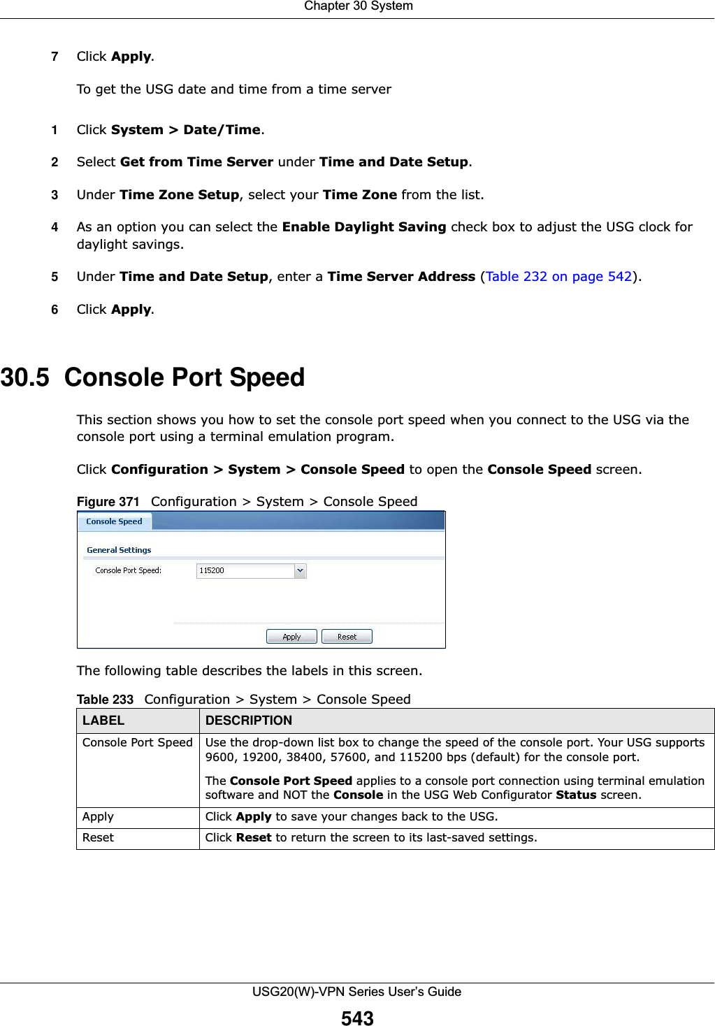
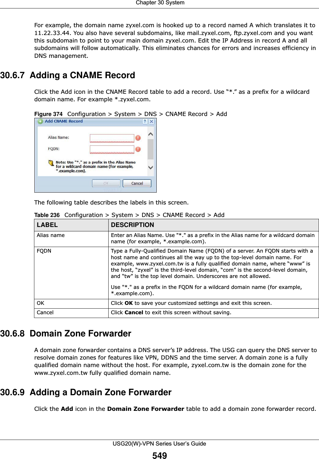
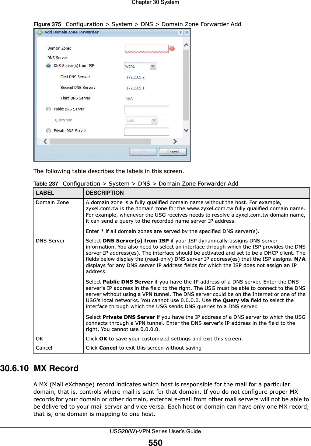
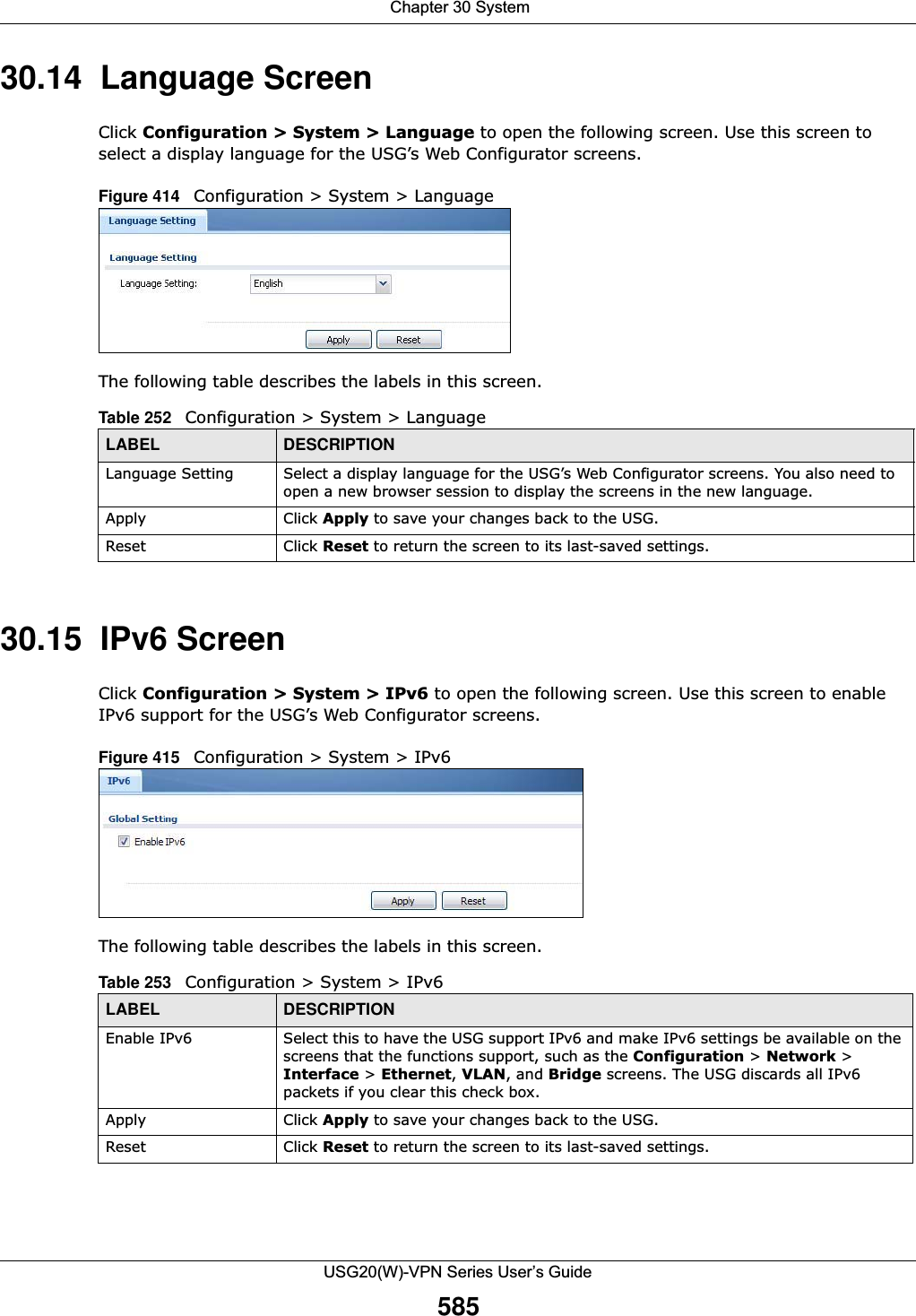
![Chapter 30 SystemUSG20(W)-VPN Series User’s Guide546IP Address This is the IP address of a host.CNAME Record This record specifies an alias for a FQDN. Use this record to bind all subdomains with the same IP address as the FQDN without having to update each one individually, which increases chance for errors. See CNAME Record (Section 30.6.6 on page 548) for more details.Add Click this to create a new entry.Edit Double-click an entry or select it and click Edit to be able to modify the entry’s settings.Remove To remove an entry, select it and click Remove. The USG confirms you want to remove it before doing so. Note that subsequent entries move up by one when you take this action.#This is the index number of the domain zone forwarder record. The ordering of your rules is important as rules are applied in sequence. A hyphen (-) displays for the default domain zone forwarder record. The default record is not configurable. The USG uses this default record if the domain zone that needs to be resolved does not match any of the other domain zone forwarder records.Alias Name Enter an Alias name. Use “*.” as prefix for a wildcard domain name. For example, *.example.com.FQDN Enter the Fully Qualified Domain Name (FQDN).Domain Zone ForwarderThis specifies a DNS server’s IP address. The USG can query the DNS server to resolve domain zones for features like VPN, DDNS and the time server.When the USG needs to resolve a domain zone, it checks it against the domain zone forwarder entries in the order that they appear in this list. Add Click this to create a new entry. Select an entry and click Add to create a new entry after the selected entry.Edit Double-click an entry or select it and click Edit to be able to modify the entry’s settings. Remove To remove an entry, select it and click Remove. The USG confirms you want to remove it before doing so. Note that subsequent entries move up by one when you take this action.Move To change an entry’s position in the numbered list, select the method and click Move to display a field to type a number for where you want to put it and press [ENTER] to move the rule to the number that you typed.#This is the index number of the domain zone forwarder record. The ordering of your rules is important as rules are applied in sequence. A hyphen (-) displays for the default domain zone forwarder record. The default record is not configurable. The USG uses this default record if the domain zone that needs to be resolved does not match any of the other domain zone forwarder records.Domain Zone A domain zone is a fully qualified domain name without the host. For example, zyxel.com.tw is the domain zone for the www.zyxel.com.tw fully qualified domain name.A “*” means all domain zones. Type This displays whether the DNS server IP address is assigned by the ISP dynamically through a specified interface or configured manually (User-Defined).DNS Server This is the IP address of a DNS server. This field displays N/A if you have the USG get a DNS server IP address from the ISP dynamically but the specified interface is not active.Query Via This is the interface through which the USG sends DNS queries to the entry’s DNS server. If the USG connects through a VPN tunnel, tunnel displays.MX Record (for My FQDN)A MX (Mail eXchange) record identifies a mail server that handles the mail for a particular domain.Add Click this to create a new entry.Edit Double-click an entry or select it and click Edit to be able to modify the entry’s settings. Table 234 Configuration > System > DNS (continued)LABEL DESCRIPTION](https://usermanual.wiki/ZyXEL-Communications/USG20W-VPN.Users-Manual-Part-5/User-Guide-2904717-Page-10.png)
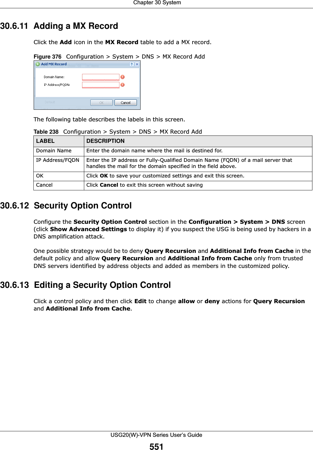
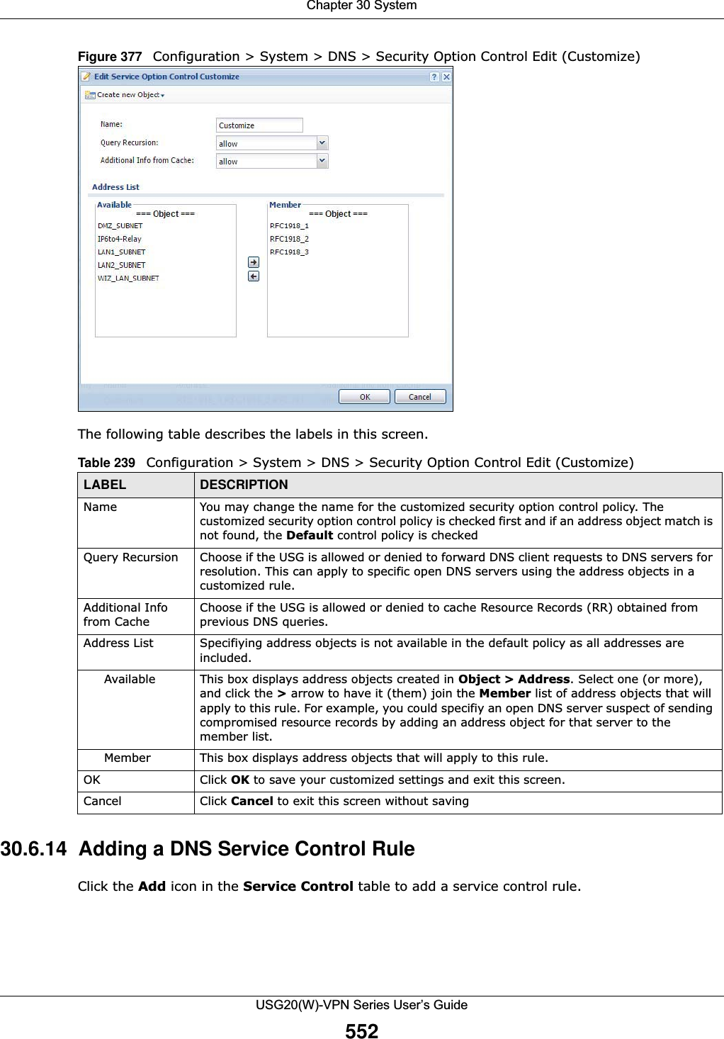
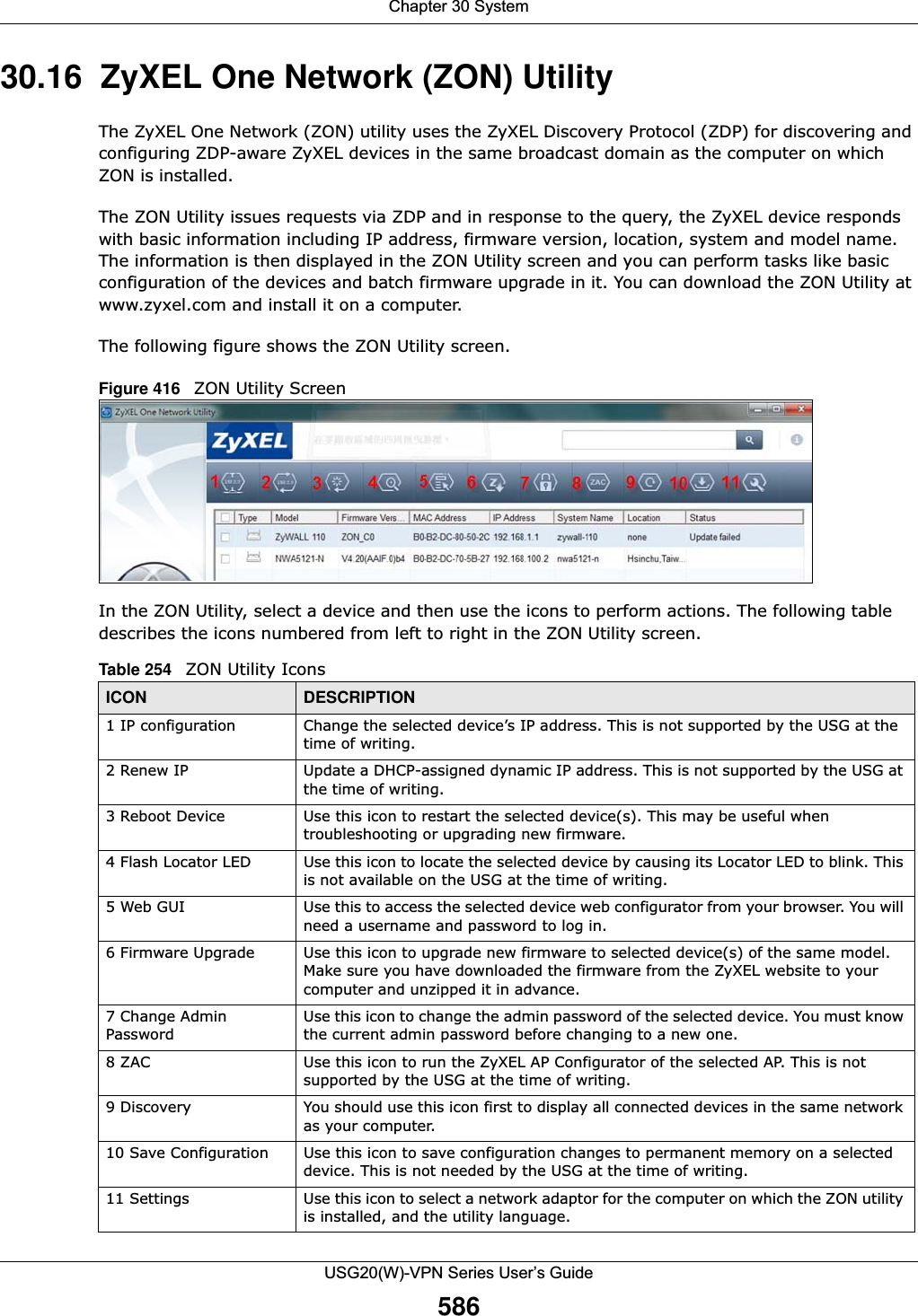
![Chapter 30 SystemUSG20(W)-VPN Series User’s Guide54730.6.3 Address Record An address record contains the mapping of a Fully-Qualified Domain Name (FQDN) to an IP address. An FQDN consists of a host and domain name. For example, www.zyxel.com is a fully qualified domain name, where “www” is the host, “zyxel” is the second-level domain, and “com” is the top level domain. mail.myZyXEL.com.tw is also a FQDN, where “mail” is the host, “myZyXEL” is the third-level domain, “com” is the second-level domain, and “tw” is the top level domain.Remove To remove an entry, select it and click Remove. The USG confirms you want to remove it before doing so. Note that subsequent entries move up by one when you take this action.#This is the index number of the MX record.Domain Name This is the domain name where the mail is destined for.IP/FQDN This is the IP address or Fully-Qualified Domain Name (FQDN) of a mail server that handles the mail for the domain specified in the field above.Security Option ControlClick Show Advanced Settings to display this part of the screen. There are two control policies: Default and Customize.Edit Click either control policy and then click this button to change allow or deny actions for Query Recursion and Additional Info from Cache.Priority The Customize control policy is checked first and if an address object match is not found, the Default control policy is checked.Name You may change the name of the Customize control policy.Address These are the object addresses used in the control policy. RFC1918 refers to private IP address ranges. It can be modified in Object > Address.Additional Info from Cache This displays if the USG is allowed or denied to cache Resource Records (RR) obtained from previous DNS queries. Query Recursion This displays if the USG is allowed or denied to forward DNS client requests to DNS servers for resolution.Service Control This specifies from which computers and zones you can send DNS queries to the USG.Add Click this to create a new entry. Select an entry and click Add to create a new entry after the selected entry.Edit Double-click an entry or select it and click Edit to be able to modify the entry’s settings. Remove To remove an entry, select it and click Remove. The USG confirms you want to remove it before doing so. Note that subsequent entries move up by one when you take this action.Move To change an entry’s position in the numbered list, select the method and click Move to display a field to type a number for where you want to put it and press [ENTER] to move the rule to the number that you typed.#This the index number of the service control rule. The ordering of your rules is important as rules are applied in sequence.The entry with a hyphen (-) instead of a number is the USG’s (non-configurable) default policy. The USG applies this to traffic that does not match any other configured rule. It is not an editable rule. To apply other behavior, configure a rule that traffic will match so the USG will not have to use the default policy.Zone This is the zone on the USG the user is allowed or denied to access.Address This is the object name of the IP address(es) with which the computer is allowed or denied to send DNS queries.Action This displays whether the USG accepts DNS queries from the computer with the IP address specified above through the specified zone (Accept) or discards them (Deny).Table 234 Configuration > System > DNS (continued)LABEL DESCRIPTION](https://usermanual.wiki/ZyXEL-Communications/USG20W-VPN.Users-Manual-Part-5/User-Guide-2904717-Page-11.png)
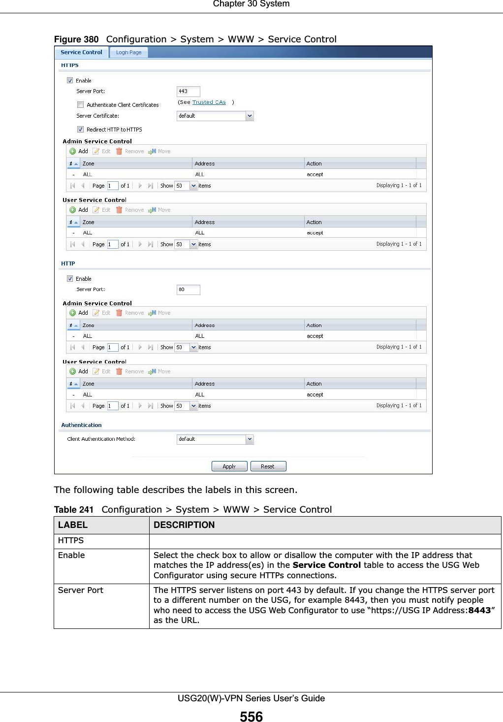
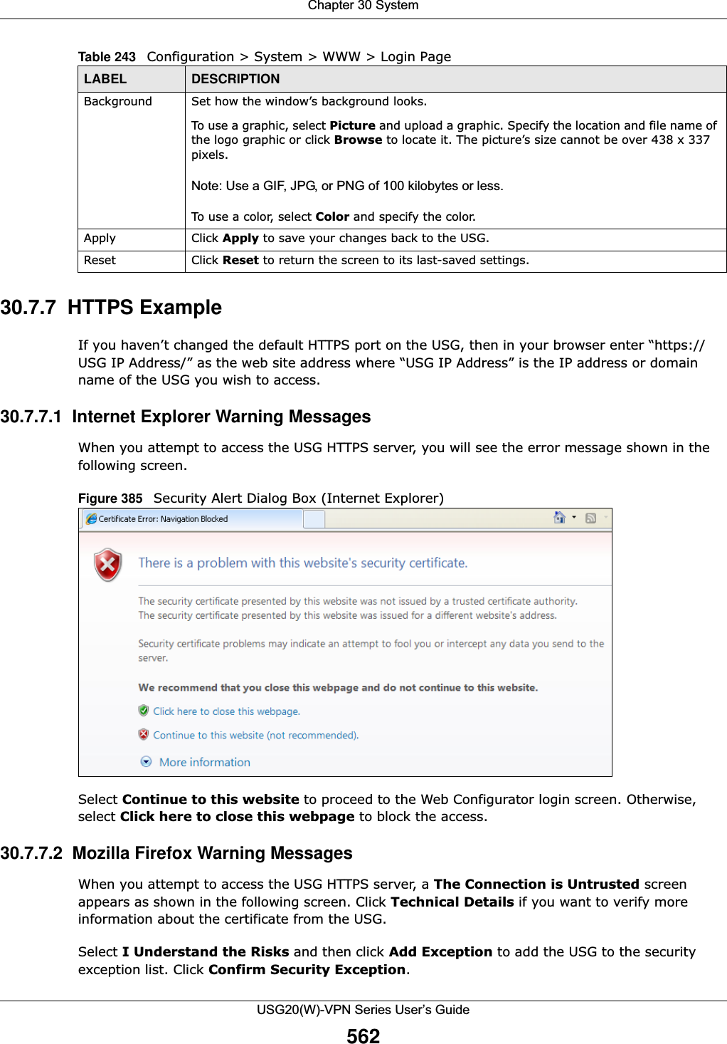
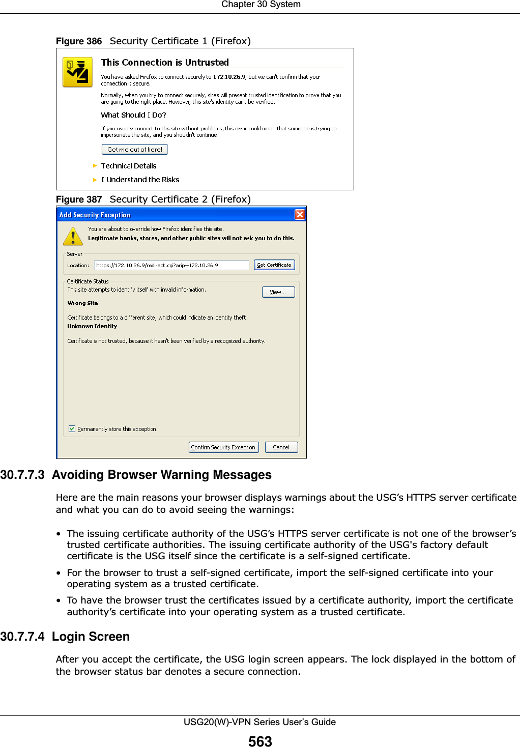
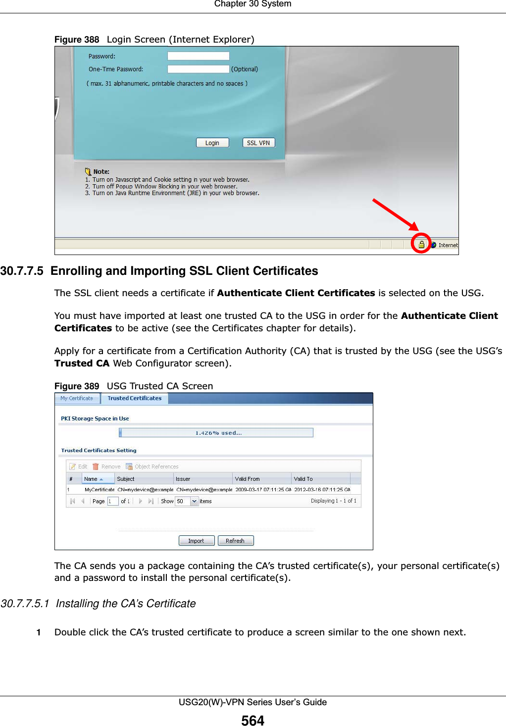
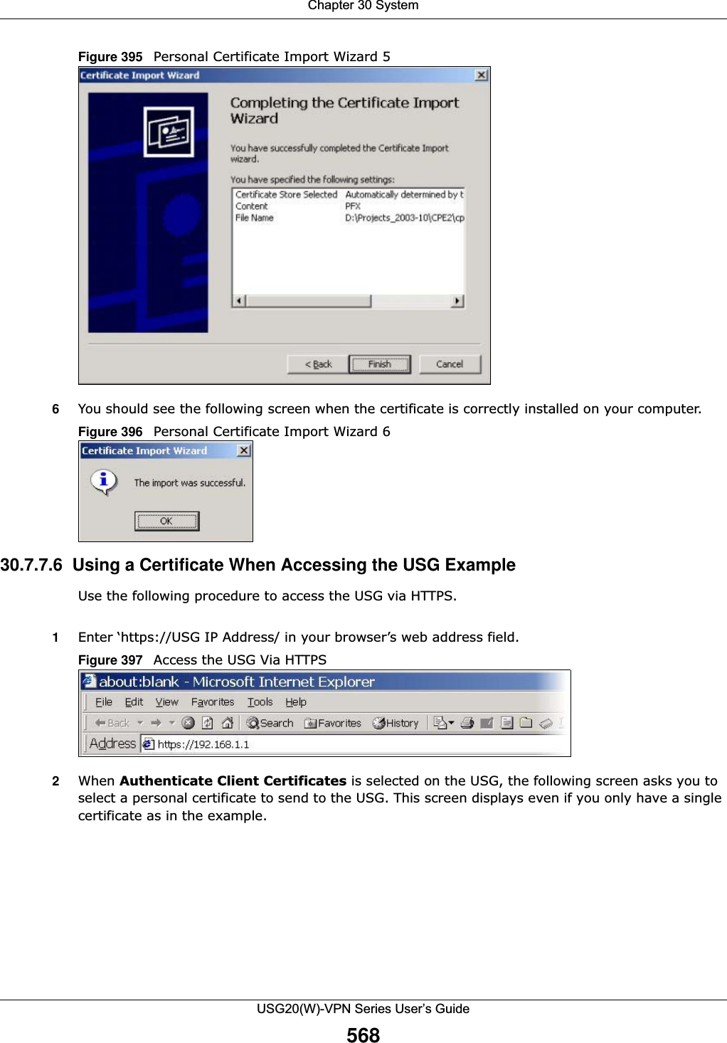
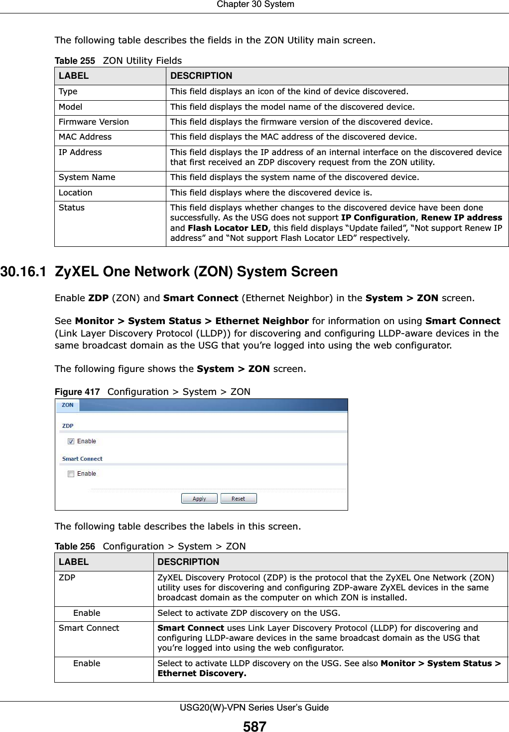
![Chapter 30 SystemUSG20(W)-VPN Series User’s Guide557Authenticate Client CertificatesSelect Authenticate Client Certificates (optional) to require the SSL client to authenticate itself to the USG by sending the USG a certificate. To do that the SSL client must have a CA-signed certificate from a CA that has been imported as a trusted CA on the USG (see Section 30.7.7.5 on page 564 on importing certificates for details).Server Certificate Select a certificate the HTTPS server (the USG) uses to authenticate itself to the HTTPS client. You must have certificates already configured in the My Certificates screen.Redirect HTTP to HTTPS To allow only secure Web Configurator access, select this to redirect all HTTP connection requests to the HTTPS server.Admin/User Service ControlAdmin Service Control specifies from which zones an administrator can use HTTPS to manage the USG (using the Web Configurator). You can also specify the IP addresses from which the administrators can manage the USG. User Service Control specifies from which zones a user can use HTTPS to log into the USG (to log into SSL VPN for example). You can also specify the IP addresses from which the users can access the USG. Add Click this to create a new entry. Select an entry and click Add to create a new entry after the selected entry.Edit Double-click an entry or select it and click Edit to be able to modify the entry’s settings. Remove To remove an entry, select it and click Remove. The USG confirms you want to remove it before doing so. Note that subsequent entries move up by one when you take this action.Move To change an entry’s position in the numbered list, select the method and click Move to display a field to type a number for where you want to put it and press [ENTER] to move the rule to the number that you typed.#This is the index number of the service control rule.The entry with a hyphen (-) instead of a number is the USG’s (non-configurable) default policy. The USG applies this to traffic that does not match any other configured rule. It is not an editable rule. To apply other behavior, configure a rule that traffic will match so the USG will not have to use the default policy.Zone This is the zone on the USG the user is allowed or denied to access.Address This is the object name of the IP address(es) with which the computer is allowed or denied to access.Action This displays whether the computer with the IP address specified above can access the USG zone(s) configured in the Zone field (Accept) or not (Deny).HTTPEnable Select the check box to allow or disallow the computer with the IP address that matches the IP address(es) in the Service Control table to access the USG Web Configurator using HTTP connections.Server Port You may change the server port number for a service if needed, however you must use the same port number in order to use that service to access the USG.Admin/User Service ControlAdmin Service Control specifies from which zones an administrator can use HTTP to manage the USG (using the Web Configurator). You can also specify the IP addresses from which the administrators can manage the USG. User Service Control specifies from which zones a user can use HTTP to log into the USG (to log into SSL VPN for example). You can also specify the IP addresses from which the users can access the USG. Add Click this to create a new entry. Select an entry and click Add to create a new entry after the selected entry.Table 241 Configuration > System > WWW > Service Control (continued)LABEL DESCRIPTION](https://usermanual.wiki/ZyXEL-Communications/USG20W-VPN.Users-Manual-Part-5/User-Guide-2904717-Page-21.png)
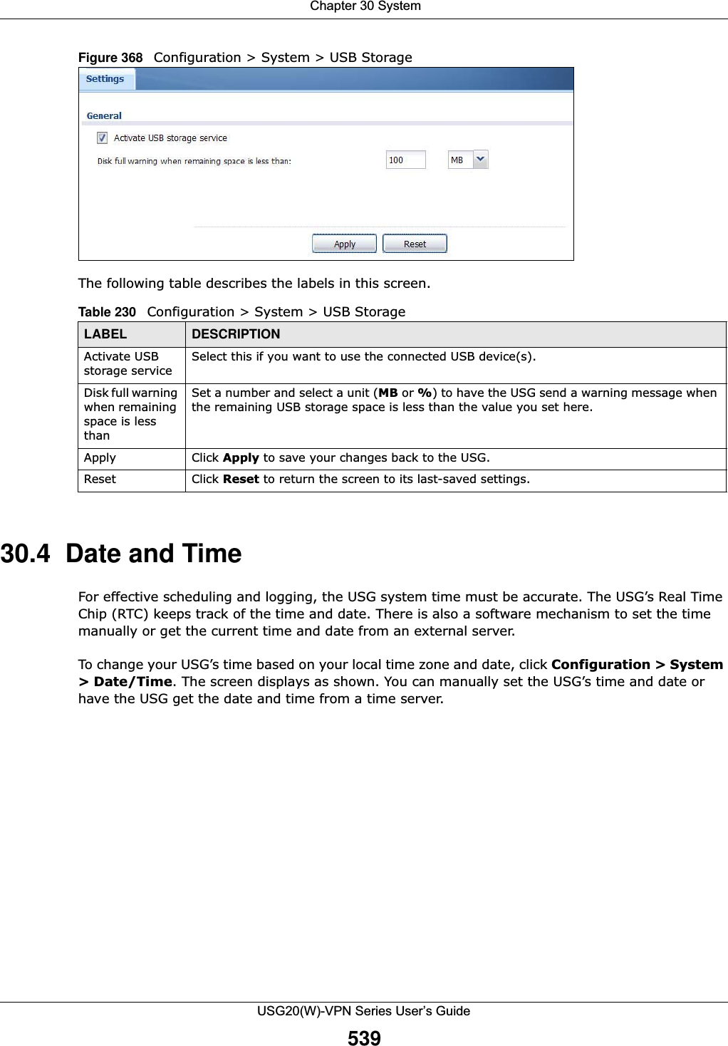
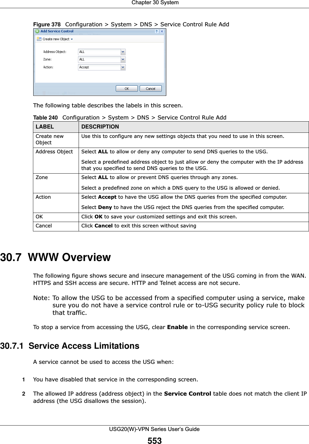
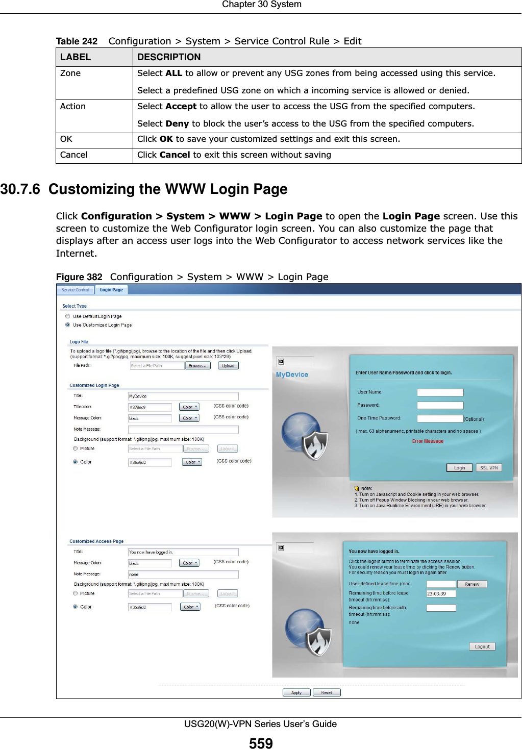
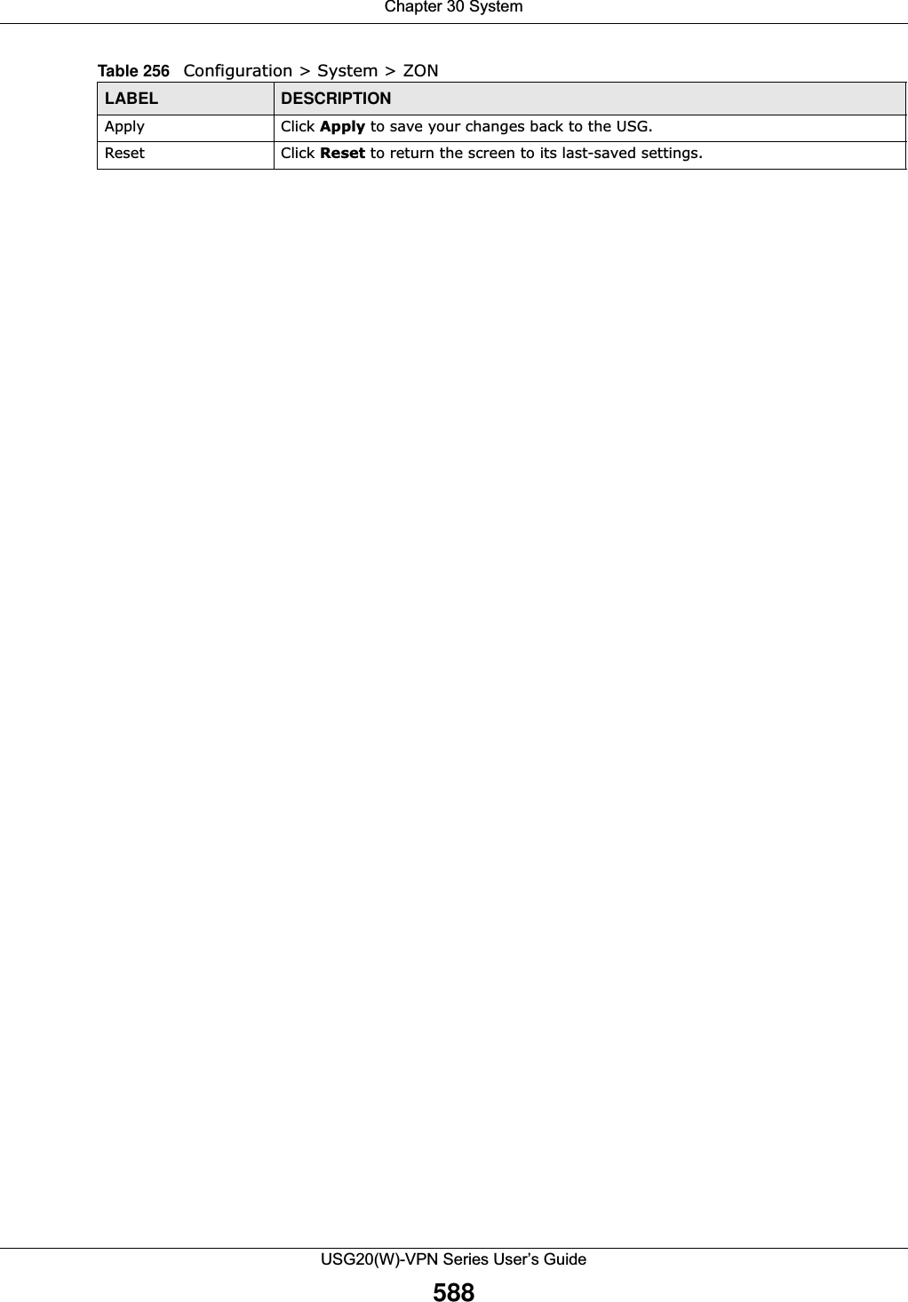
![Chapter 30 SystemUSG20(W)-VPN Series User’s Guide55830.7.5 Service Control RulesClick Add or Edit in the Service Control table in a WWW, SSH, Telnet, FTP or SNMP screen to add a service control rule. Figure 381 Configuration > System > Service Control Rule > Edit The following table describes the labels in this screen. Edit Double-click an entry or select it and click Edit to be able to modify the entry’s settings. Remove To remove an entry, select it and click Remove. The USG confirms you want to remove it before doing so. Note that subsequent entries move up by one when you take this action.Move To change an entry’s position in the numbered list, select the method and click Move to display a field to type a number for where you want to put it and press [ENTER] to move the rule to the number that you typed.#This is the index number of the service control rule.The entry with a hyphen (-) instead of a number is the USG’s (non-configurable) default policy. The USG applies this to traffic that does not match any other configured rule. It is not an editable rule. To apply other behavior, configure a rule that traffic will match so the USG will not have to use the default policy.Zone This is the zone on the USG the user is allowed or denied to access.Address This is the object name of the IP address(es) with which the computer is allowed or denied to access.Action This displays whether the computer with the IP address specified above can access the USG zone(s) configured in the Zone field (Accept) or not (Deny).AuthenticationClient Authentication MethodSelect a method the HTTPS or HTTP server uses to authenticate a client.You must have configured the authentication methods in the Auth. method screen.Apply Click Apply to save your changes back to the USG. Reset Click Reset to return the screen to its last-saved settings. Table 241 Configuration > System > WWW > Service Control (continued)LABEL DESCRIPTIONTable 242 Configuration > System > Service Control Rule > EditLABEL DESCRIPTIONCreate new ObjectUse this to configure any new settings objects that you need to use in this screen.Address Object Select ALL to allow or deny any computer to communicate with the USG using this service.Select a predefined address object to just allow or deny the computer with the IP address that you specified to access the USG using this service.](https://usermanual.wiki/ZyXEL-Communications/USG20W-VPN.Users-Manual-Part-5/User-Guide-2904717-Page-22.png)
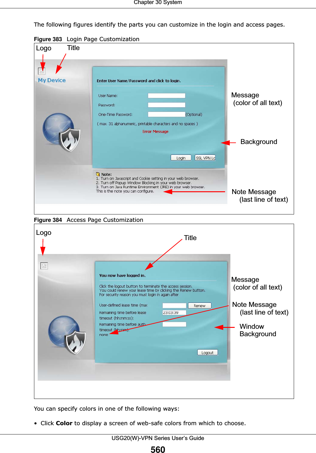
![Chapter 30 SystemUSG20(W)-VPN Series User’s Guide561• Enter the name of the desired color. • Enter a pound sign (#) followed by the six-digit hexadecimal number that represents the desired color. For example, use “#000000” for black.• Enter “rgb” followed by red, green, and blue values in parenthesis and separate by commas. For example, use “rgb(0,0,0)” for black.Your desired color should display in the preview screen on the right after you click in another field, click Apply, or press [ENTER]. If your desired color does not display, your browser may not support it. Try selecting another color. The following table describes the labels in the screen. Table 243 Configuration > System > WWW > Login PageLABEL DESCRIPTIONSelect Type Select whether the Web Configurator uses the default login screen or one that you customize in the rest of this screen.Logo File You can upload a graphic logo to be displayed on the upper left corner of the Web Configurator login screen and access page. Specify the location and file name of the logo graphic or click Browse to locate it. Note: Use a GIF, JPG, or PNG of 100 kilobytes or less. Click Upload to transfer the specified graphic file from your computer to the USG. Customized Login PageUse this section to set how the Web Configurator login screen looks. Title Enter the title for the top of the screen. Use up to 64 printable ASCII characters. Spaces are allowed. Title Color Specify the color of the screen’s title text. Message Color Specify the color of the screen’s text. Note Message Enter a note to display at the bottom of the screen. Use up to 64 printable ASCII characters. Spaces are allowed. Background Set how the screen background looks. To use a graphic, select Picture and upload a graphic. Specify the location and file name of the logo graphic or click Browse to locate it. The picture’s size cannot be over 438 x 337 pixels.Note: Use a GIF, JPG, or PNG of 100 kilobytes or less. To use a color, select Color and specify the color.Customized Access PageUse this section to customize the page that displays after an access user logs into the Web Configurator to access network services like the Internet. Title Enter the title for the top of the screen. Use up to 64 printable ASCII characters. Spaces are allowed. Message Color Specify the color of the screen’s text.Note Message Enter a note to display below the title. Use up to 64 printable ASCII characters. Spaces are allowed.](https://usermanual.wiki/ZyXEL-Communications/USG20W-VPN.Users-Manual-Part-5/User-Guide-2904717-Page-25.png)
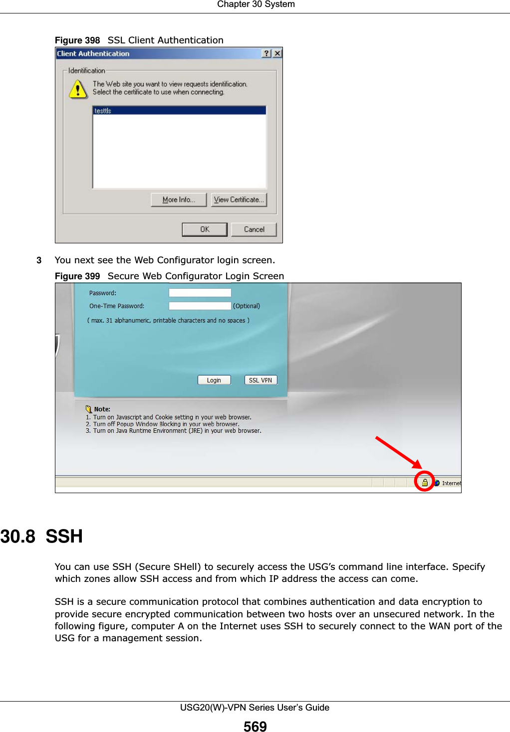
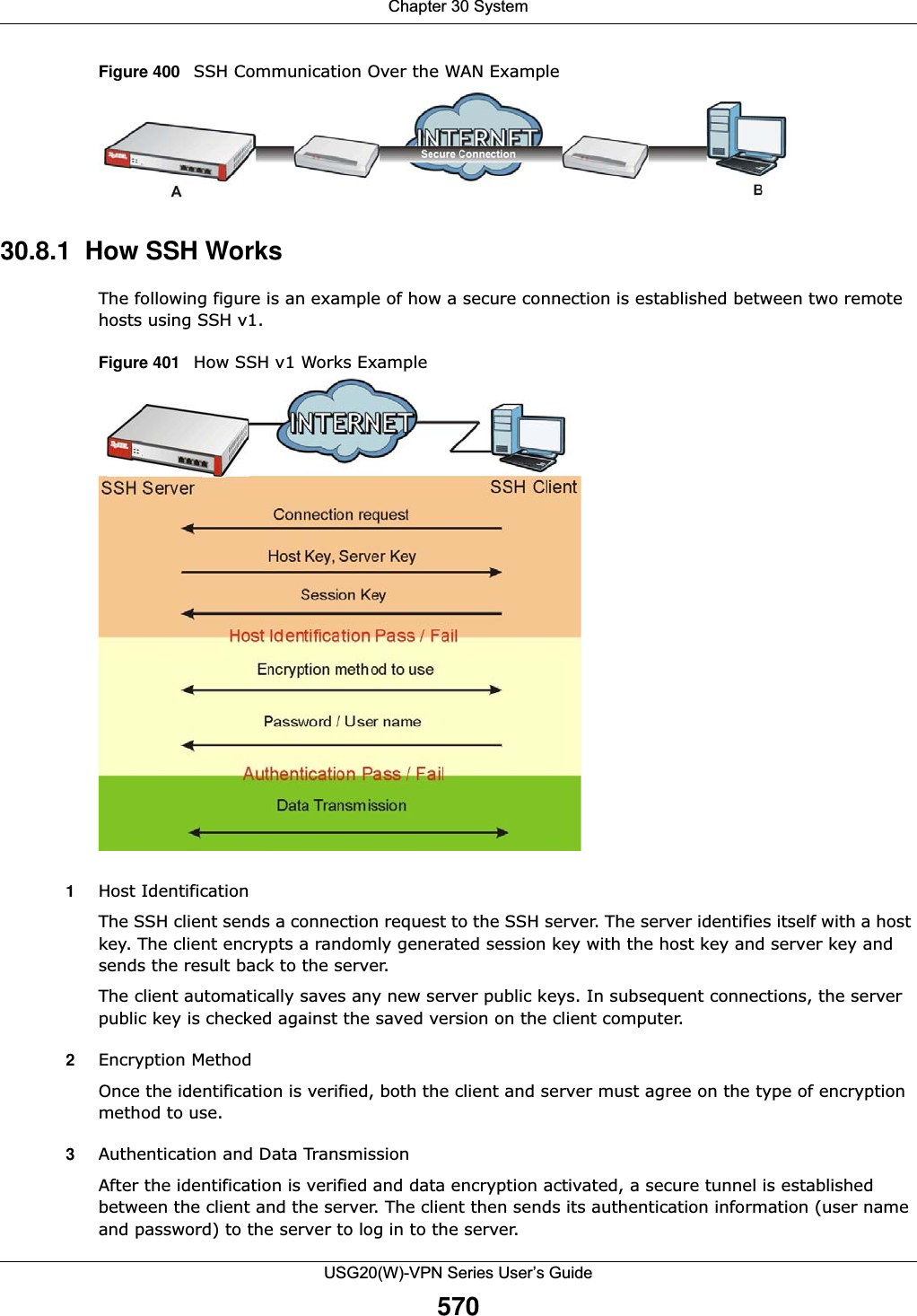
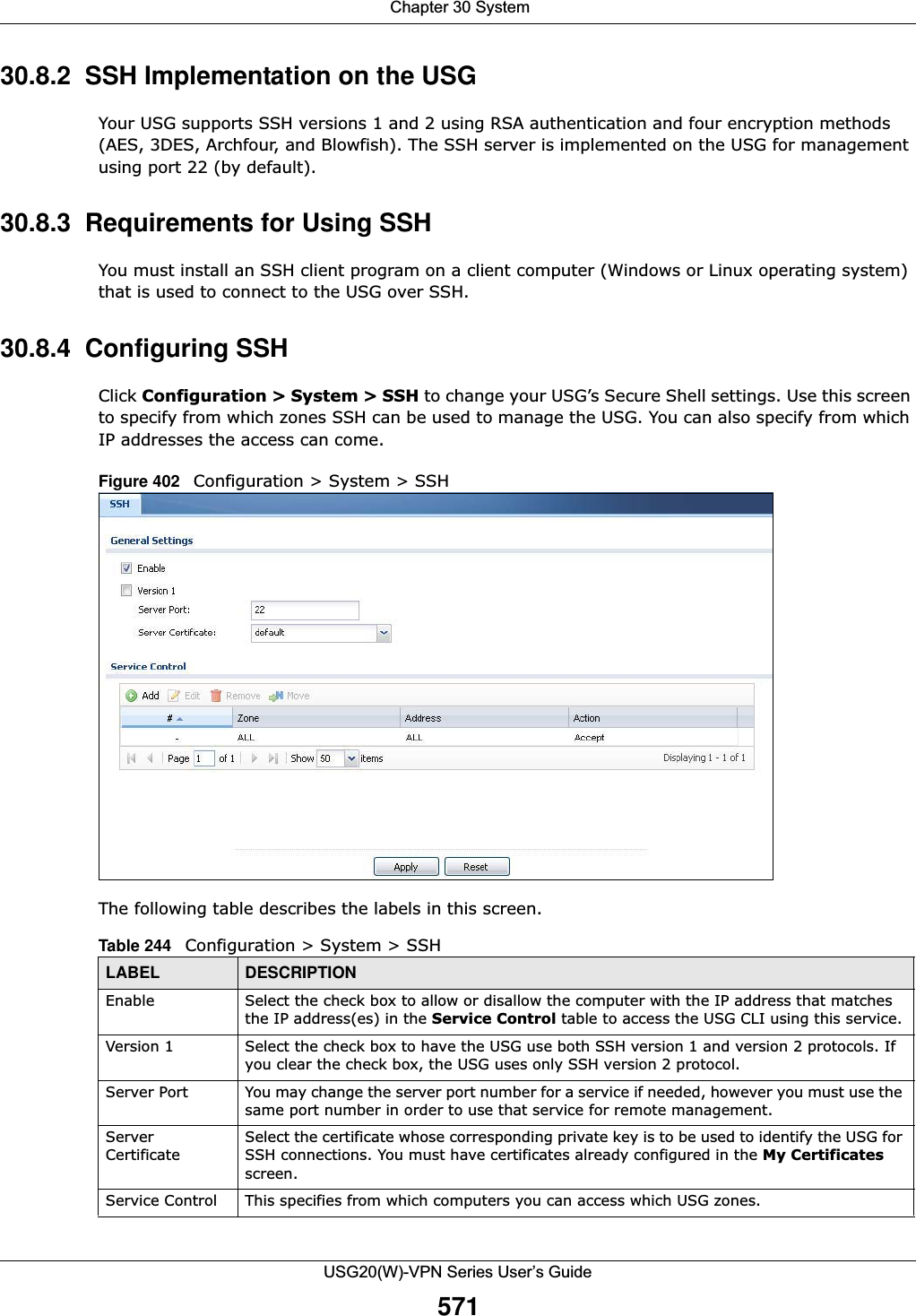
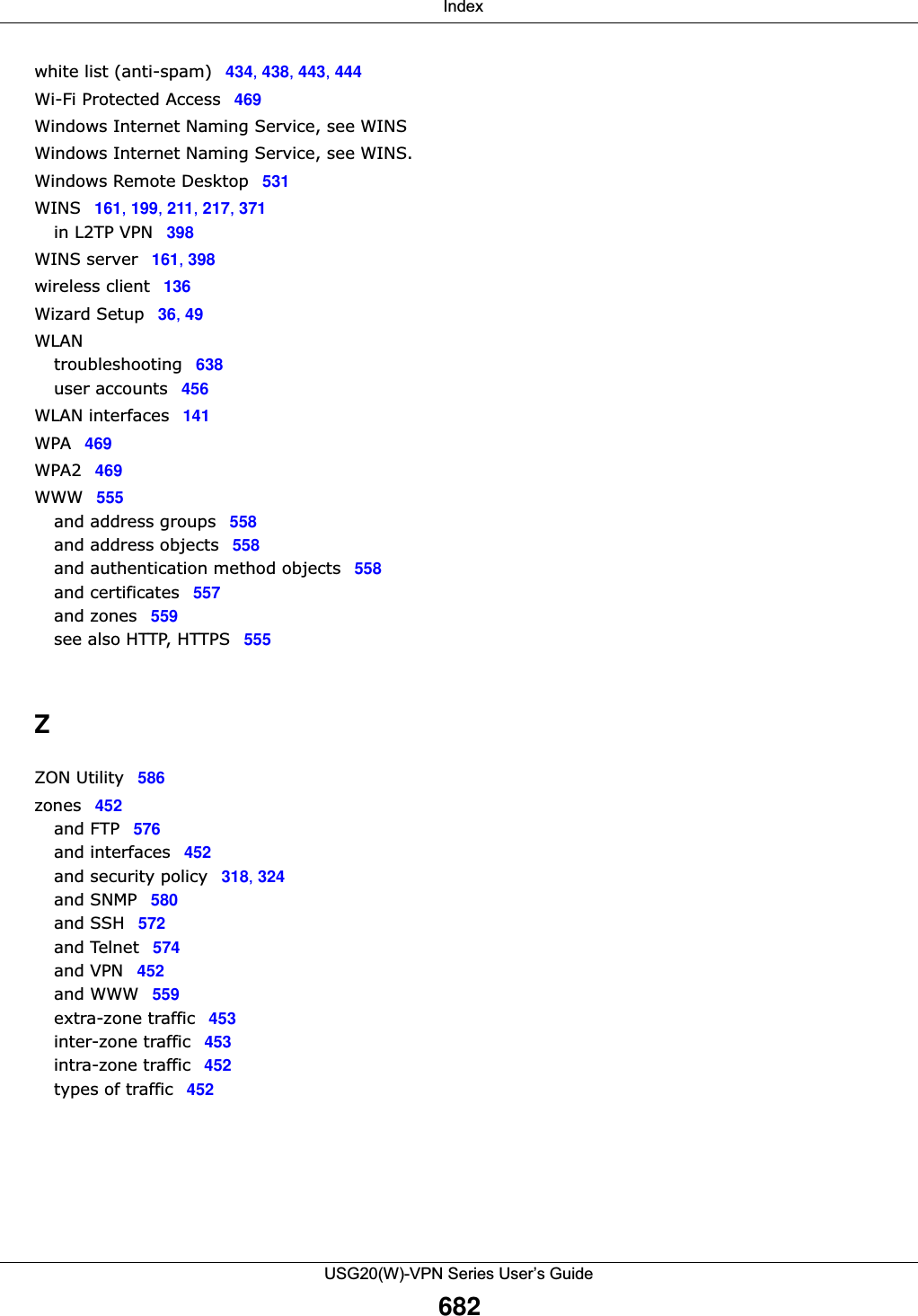
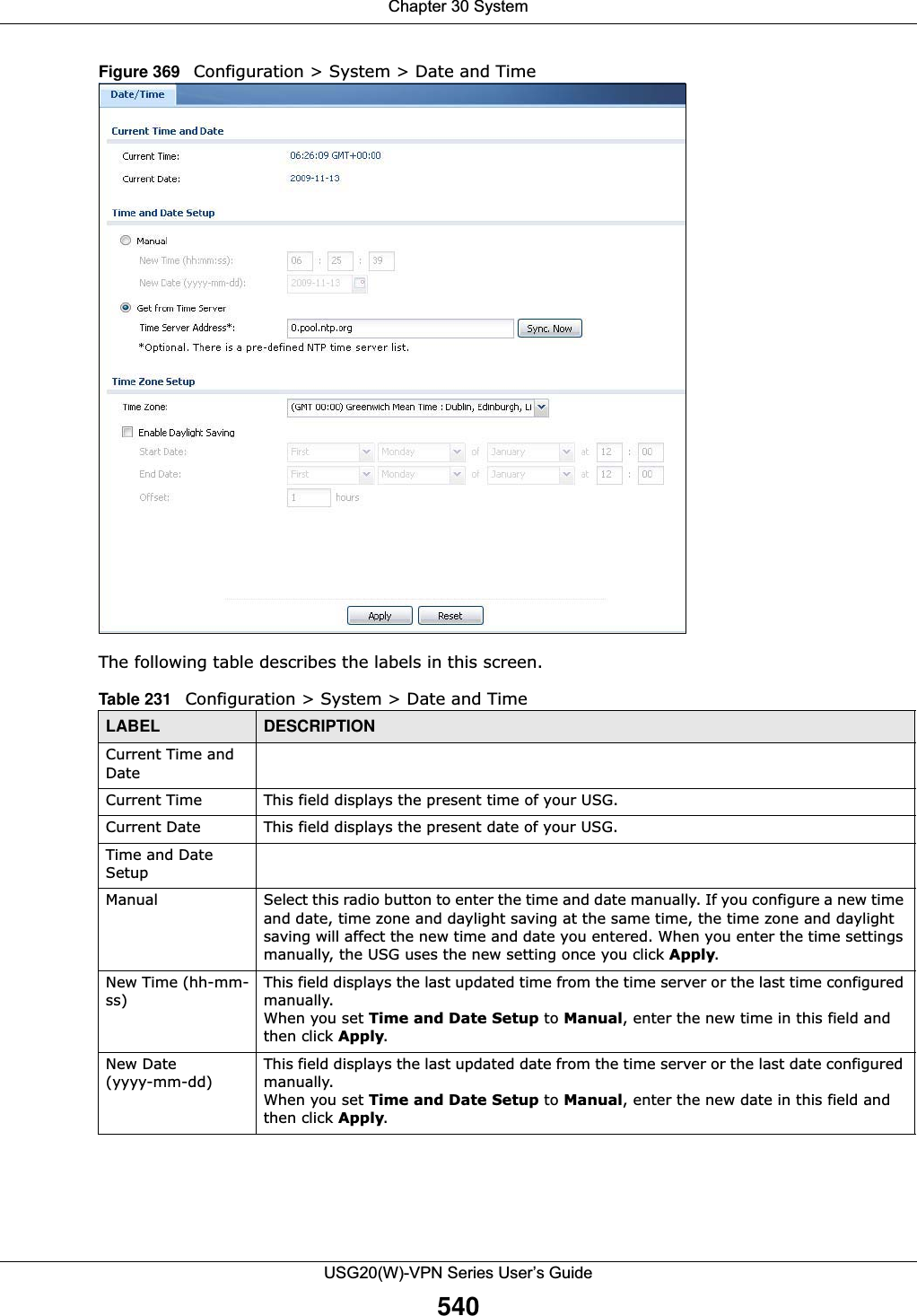
![Chapter 30 SystemUSG20(W)-VPN Series User’s Guide57230.8.5 Secure Telnet Using SSH ExamplesThis section shows two examples using a command interface and a graphical interface SSH client program to remotely access the USG. The configuration and connection steps are similar for most SSH client programs. Refer to your SSH client program user’s guide.30.8.5.1 Example 1: Microsoft Windows This section describes how to access the USG using the Secure Shell Client program.1Launch the SSH client and specify the connection information (IP address, port number) for the USG. 2Configure the SSH client to accept connection using SSH version 1. 3A window displays prompting you to store the host key in you computer. Click Yes to continue. Figure 403 SSH Example 1: Store Host KeyEnter the password to log in to the USG. The CLI screen displays next. Add Click this to create a new entry. Select an entry and click Add to create a new entry after the selected entry. Refer to Table 242 on page 558 for details on the screen that opens.Edit Double-click an entry or select it and click Edit to be able to modify the entry’s settings. Remove To remove an entry, select it and click Remove. The USG confirms you want to remove it before doing so. Note that subsequent entries move up by one when you take this action.Move To change an entry’s position in the numbered list, select the method and click Move to display a field to type a number for where you want to put it and press [ENTER] to move the rule to the number that you typed.#This the index number of the service control rule.Zone This is the zone on the USG the user is allowed or denied to access.Address This is the object name of the IP address(es) with which the computer is allowed or denied to access.Action This displays whether the computer with the IP address specified above can access the USG zone(s) configured in the Zone field (Accept) or not (Deny).Apply Click Apply to save your changes back to the USG. Reset Click Reset to return the screen to its last-saved settings. Table 244 Configuration > System > SSH (continued)LABEL DESCRIPTION](https://usermanual.wiki/ZyXEL-Communications/USG20W-VPN.Users-Manual-Part-5/User-Guide-2904717-Page-36.png)
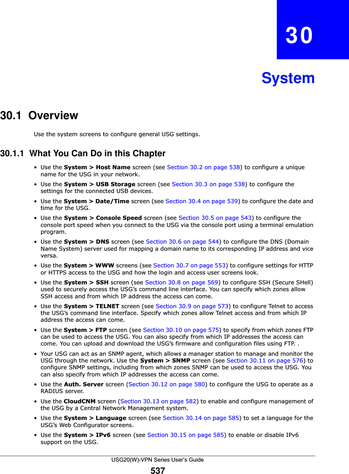
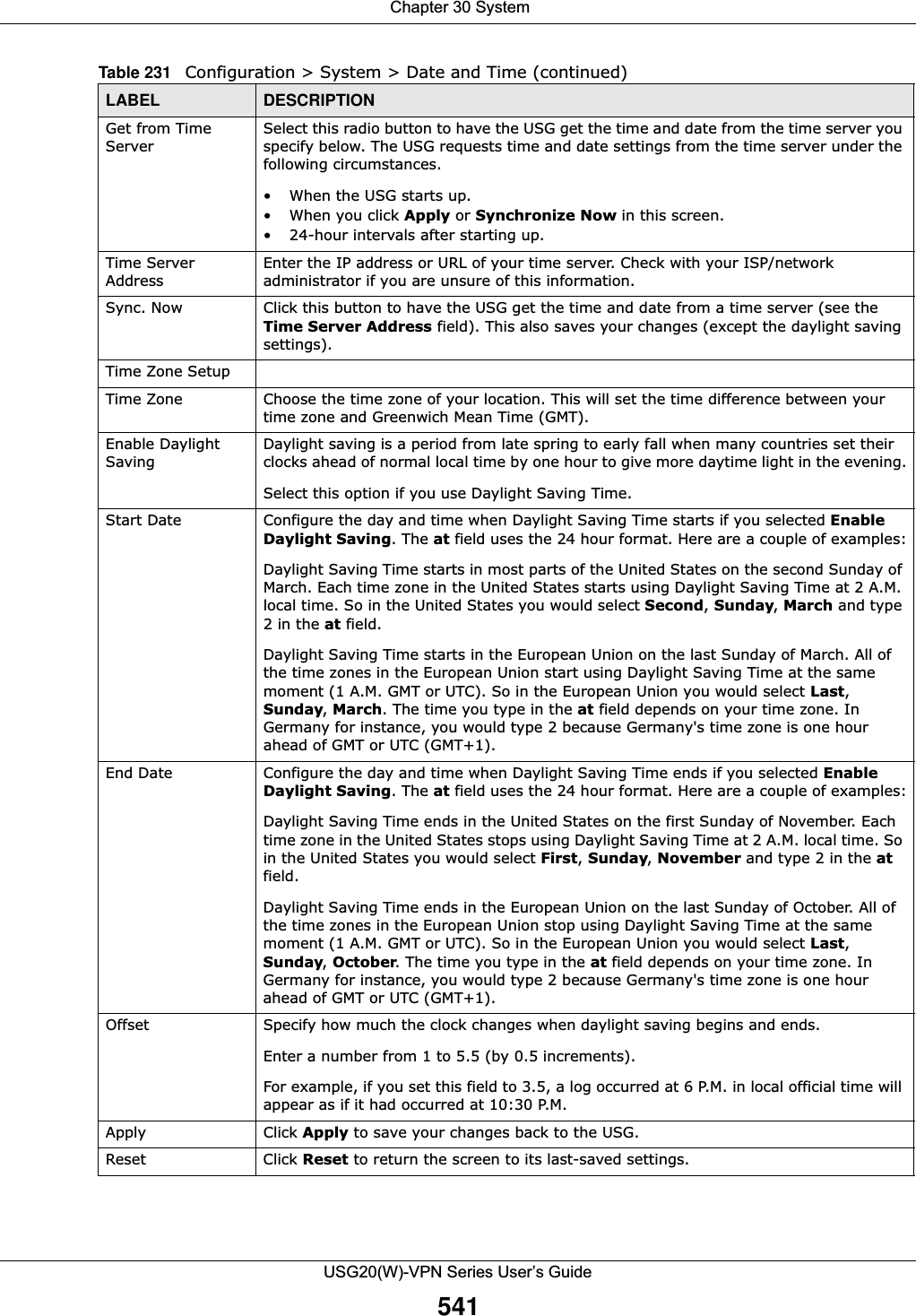
![Chapter 30 SystemUSG20(W)-VPN Series User’s Guide57330.8.5.2 Example 2: LinuxThis section describes how to access the USG using the OpenSSH client program that comes with most Linux distributions. 1Test whether the SSH service is available on the USG. Enter “telnet 192.168.1.1 22” at a terminal prompt and press [ENTER]. The computer attempts to connect to port 22 on the USG (using the default IP address of 192.168.1.1). A message displays indicating the SSH protocol version supported by the USG. Figure 404 SSH Example 2: Test 2Enter “ssh –1 192.168.1.1”. This command forces your computer to connect to the USG using SSH version 1. If this is the first time you are connecting to the USG using SSH, a message displays prompting you to save the host information of the USG. Type “yes” and press [ENTER]. Then enter the password to log in to the USG. Figure 405 SSH Example 2: Log in3The CLI screen displays next. 30.9 Telnet You can use Telnet to access the USG’s command line interface. Specify which zones allow Telnet access and from which IP address the access can come.30.9.1 Configuring TelnetClick Configuration > System > TELNET to configure your USG for remote Telnet access. Use this screen to specify from which zones Telnet can be used to manage the USG. You can also specify from which IP addresses the access can come.$ telnet 192.168.1.1 22Trying 192.168.1.1...Connected to 192.168.1.1.Escape character is '^]'.SSH-1.5-1.0.0$ ssh –1 192.168.1.1The authenticity of host '192.168.1.1 (192.168.1.1)' can't be established.RSA1 key fingerprint is 21:6c:07:25:7e:f4:75:80:ec:af:bd:d4:3d:80:53:d1.Are you sure you want to continue connecting (yes/no)? yesWarning: Permanently added '192.168.1.1' (RSA1) to the list of known hosts.Administrator@192.168.1.1's password:](https://usermanual.wiki/ZyXEL-Communications/USG20W-VPN.Users-Manual-Part-5/User-Guide-2904717-Page-37.png)
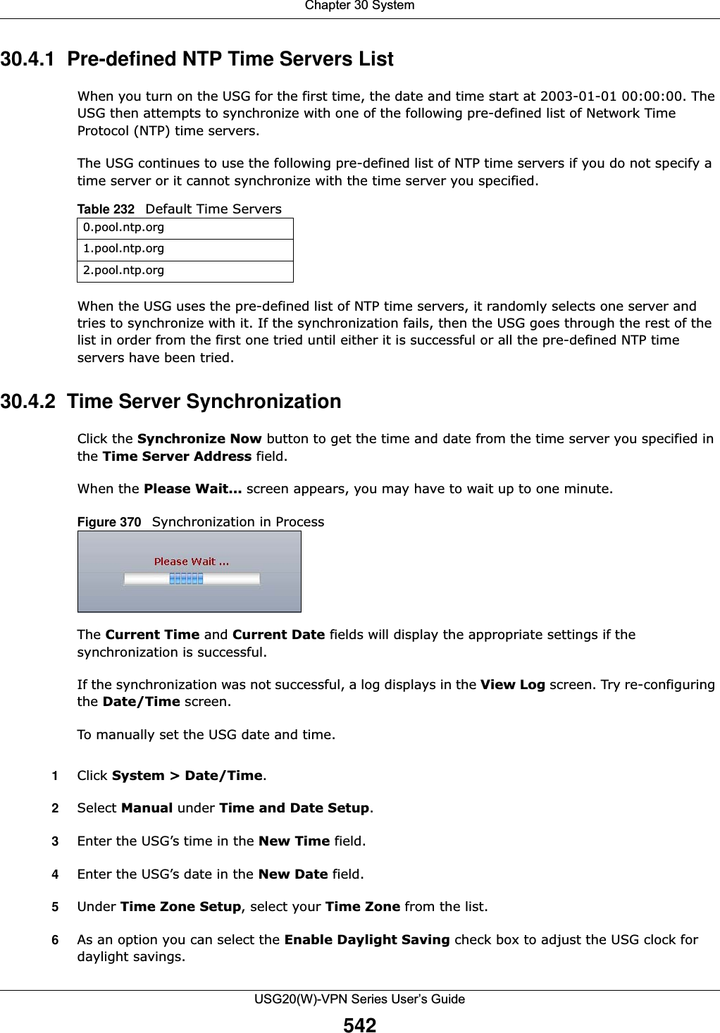
![Chapter 30 SystemUSG20(W)-VPN Series User’s Guide574Figure 406 Configuration > System > TELNETThe following table describes the labels in this screen. Table 245 Configuration > System > TELNETLABEL DESCRIPTIONEnable Select the check box to allow or disallow the computer with the IP address that matches the IP address(es) in the Service Control table to access the USG CLI using this service.Server Port You may change the server port number for a service if needed, however you must use the same port number in order to use that service for remote management.Service Control This specifies from which computers you can access which USG zones.Add Click this to create a new entry. Select an entry and click Add to create a new entry after the selected entry. Refer to Table 242 on page 558 for details on the screen that opens. Edit Double-click an entry or select it and click Edit to be able to modify the entry’s settings. Remove To remove an entry, select it and click Remove. The USG confirms you want to remove it before doing so. Note that subsequent entries move up by one when you take this action.Move To change an entry’s position in the numbered list, select the method and click Move to display a field to type a number for where you want to put it and press [ENTER] to move the rule to the number that you typed.#This the index number of the service control rule.The entry with a hyphen (-) instead of a number is the USG’s (non-configurable) default policy. The USG applies this to traffic that does not match any other configured rule. It is not an editable rule. To apply other behavior, configure a rule that traffic will match so the USG will not have to use the default policy.Zone This is the zone on the USG the user is allowed or denied to access.Address This is the object name of the IP address(es) with which the computer is allowed or denied to access.Action This displays whether the computer with the IP address specified above can access the USG zone(s) configured in the Zone field (Accept) or not (Deny).Apply Click Apply to save your changes back to the USG. Reset Click Reset to return the screen to its last-saved settings.](https://usermanual.wiki/ZyXEL-Communications/USG20W-VPN.Users-Manual-Part-5/User-Guide-2904717-Page-38.png)
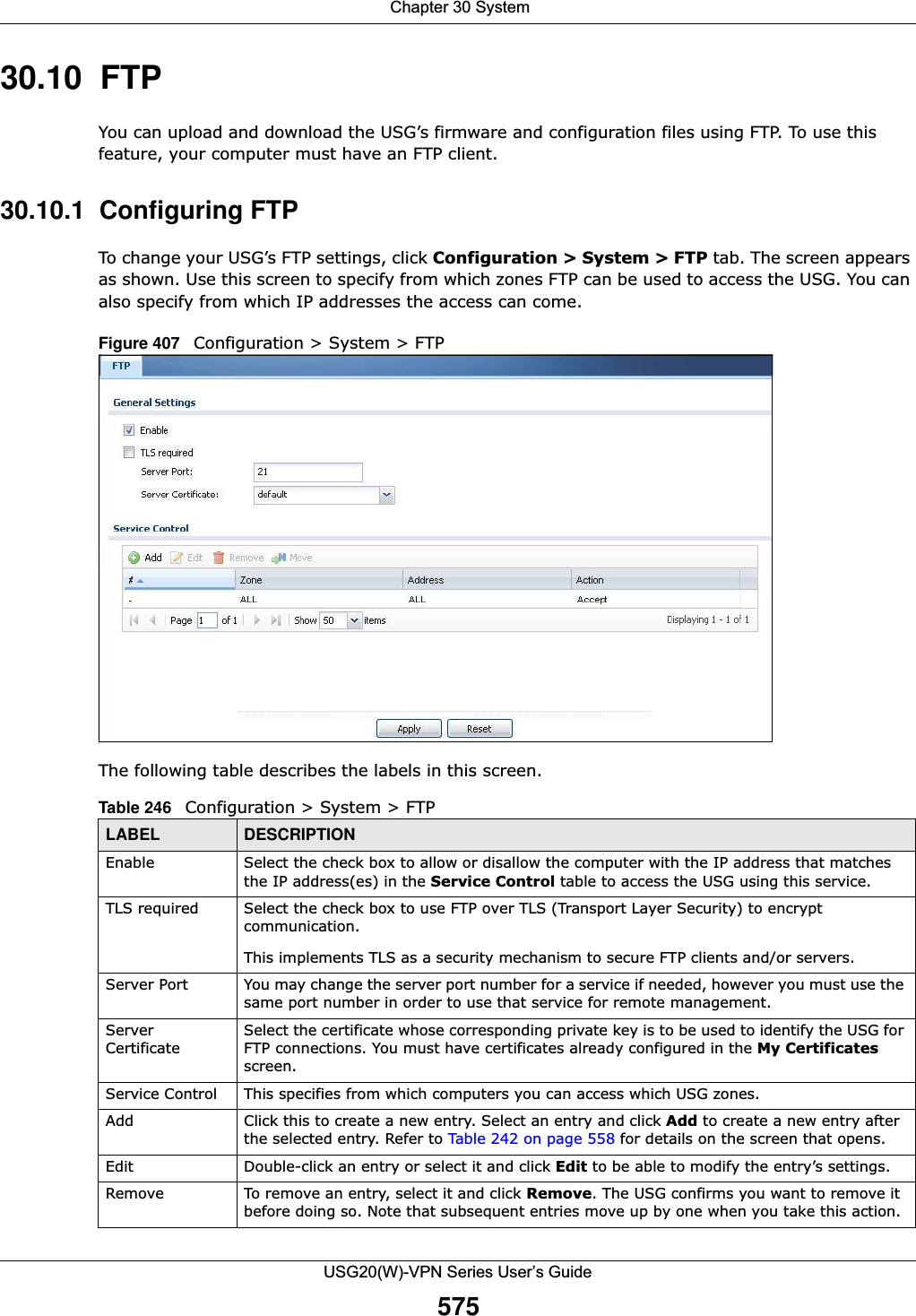
![Chapter 30 SystemUSG20(W)-VPN Series User’s Guide57630.11 SNMP Simple Network Management Protocol is a protocol used for exchanging management information between network devices. Your USG supports SNMP agent functionality, which allows a manager station to manage and monitor the USG through the network. The USG supports SNMP version one (SNMPv1), version two (SNMPv2c) and version 3 (SNMPv3). The next figure illustrates an SNMP management operation. Figure 408 SNMP Management ModelMove To change an entry’s position in the numbered list, select the method and click Move to display a field to type a number for where you want to put it and press [ENTER] to move the rule to the number that you typed.#This the index number of the service control rule.The entry with a hyphen (-) instead of a number is the USG’s (non-configurable) default policy. The USG applies this to traffic that does not match any other configured rule. It is not an editable rule. To apply other behavior, configure a rule that traffic will match so the USG will not have to use the default policy.Zone This is the zone on the USG the user is allowed or denied to access.Address This is the object name of the IP address(es) with which the computer is allowed or denied to access.Action This displays whether the computer with the IP address specified above can access the USG zone(s) configured in the Zone field (Accept) or not (Deny).Apply Click Apply to save your changes back to the USG. Reset Click Reset to return the screen to its last-saved settings. Table 246 Configuration > System > FTP (continued)LABEL DESCRIPTION](https://usermanual.wiki/ZyXEL-Communications/USG20W-VPN.Users-Manual-Part-5/User-Guide-2904717-Page-40.png)
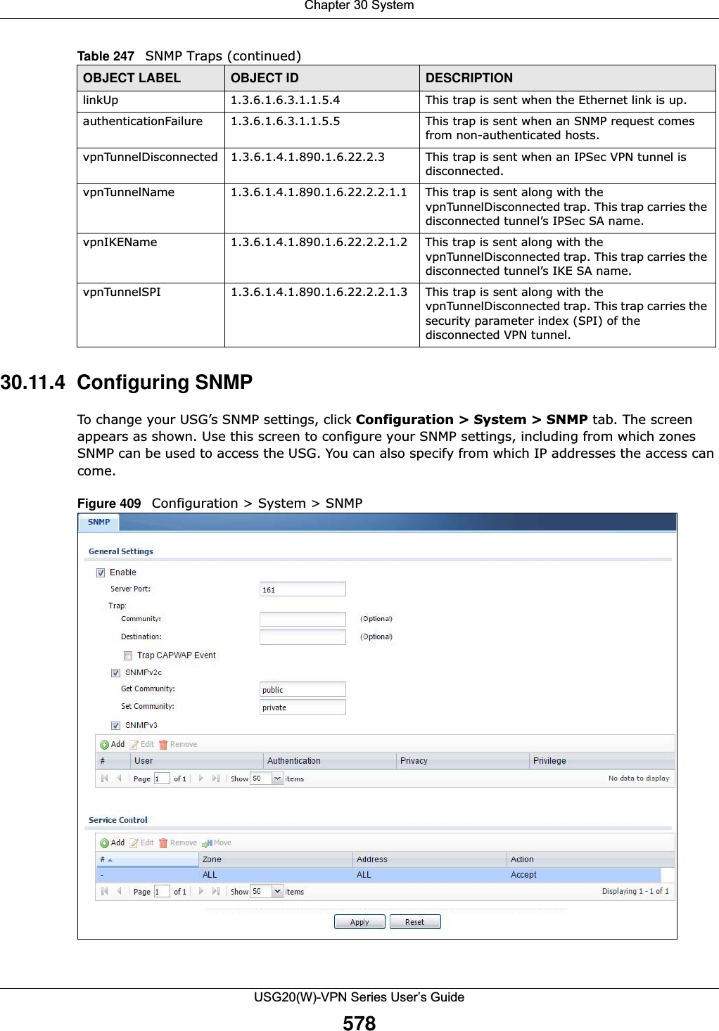
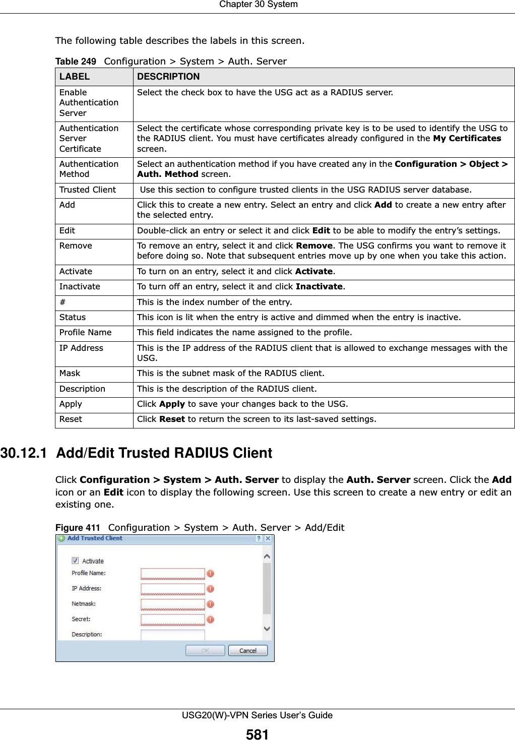
![Chapter 30 SystemUSG20(W)-VPN Series User’s Guide58030.12 Authentication ServerYou can set the USG to work as a RADIUS server to exchange messages with a RADIUS client, such as an AP for user authentication and authorization. Click Configuration > System > Auth. Server tab. The screen appears as shown. Use this screen to enable the authentication server feature of the USG and specify the RADIUS client’s IP address.Figure 410 Configuration > System > Auth. ServerMove To change an entry’s position in the numbered list, select the method and click Move to display a field to type a number for where you want to put it and press [ENTER] to move the rule to the number that you typed.#This the index number of the service control rule.The entry with a hyphen (-) instead of a number is the USG’s (non-configurable) default policy. The USG applies this to traffic that does not match any other configured rule. It is not an editable rule. To apply other behavior, configure a rule that traffic will match so the USG will not have to use the default policy.Zone This is the zone on the USG the user is allowed or denied to access.Address This is the object name of the IP address(es) with which the computer is allowed or denied to access.Action This displays whether the computer with the IP address specified above can access the USG zone(s) configured in the Zone field (Accept) or not (Deny).Apply Click Apply to save your changes back to the USG. Reset Click Reset to return the screen to its last-saved settings. Table 248 Configuration > System > SNMP (continued)LABEL DESCRIPTION](https://usermanual.wiki/ZyXEL-Communications/USG20W-VPN.Users-Manual-Part-5/User-Guide-2904717-Page-44.png)
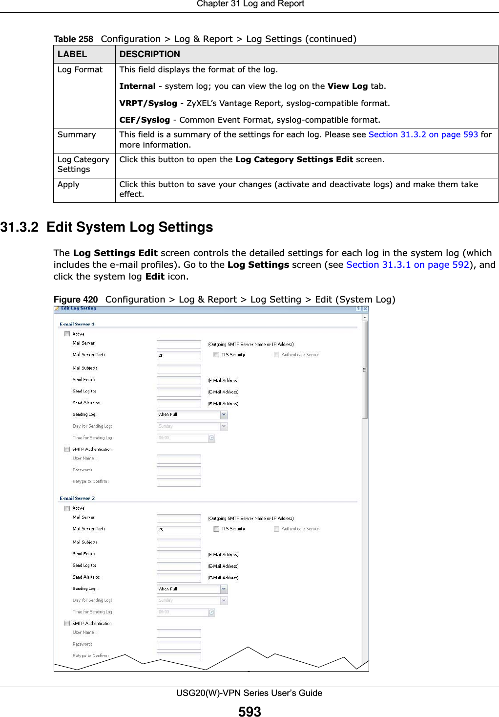
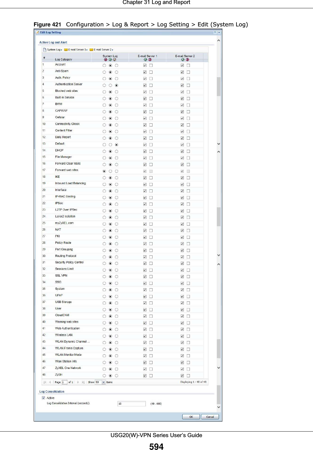
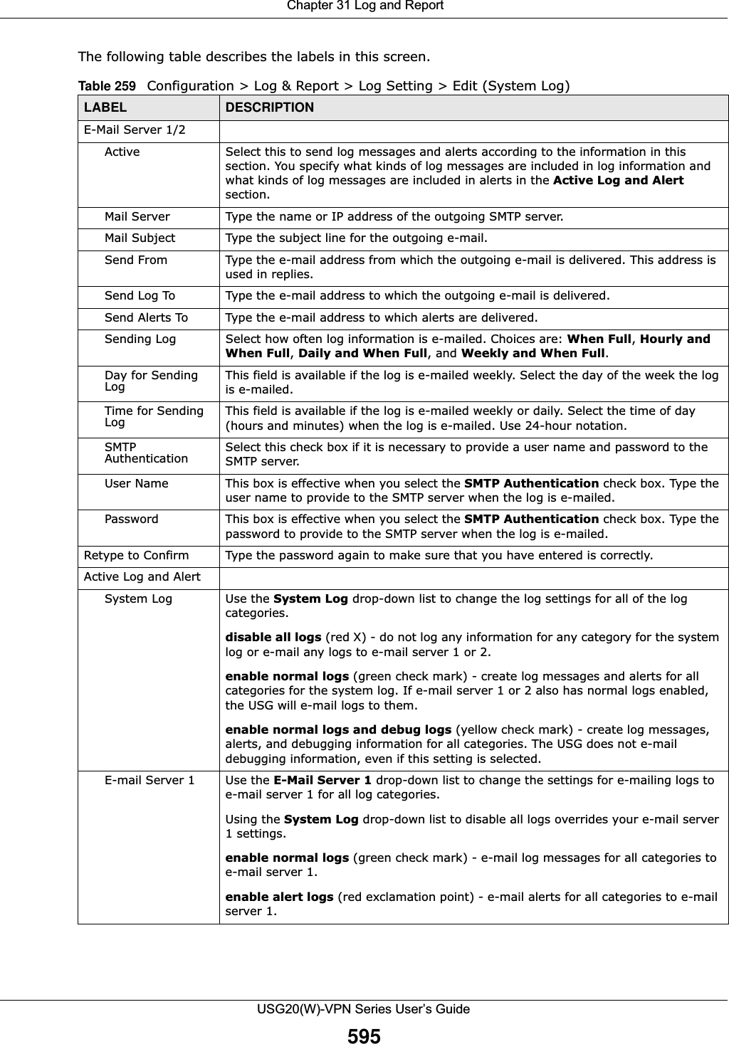
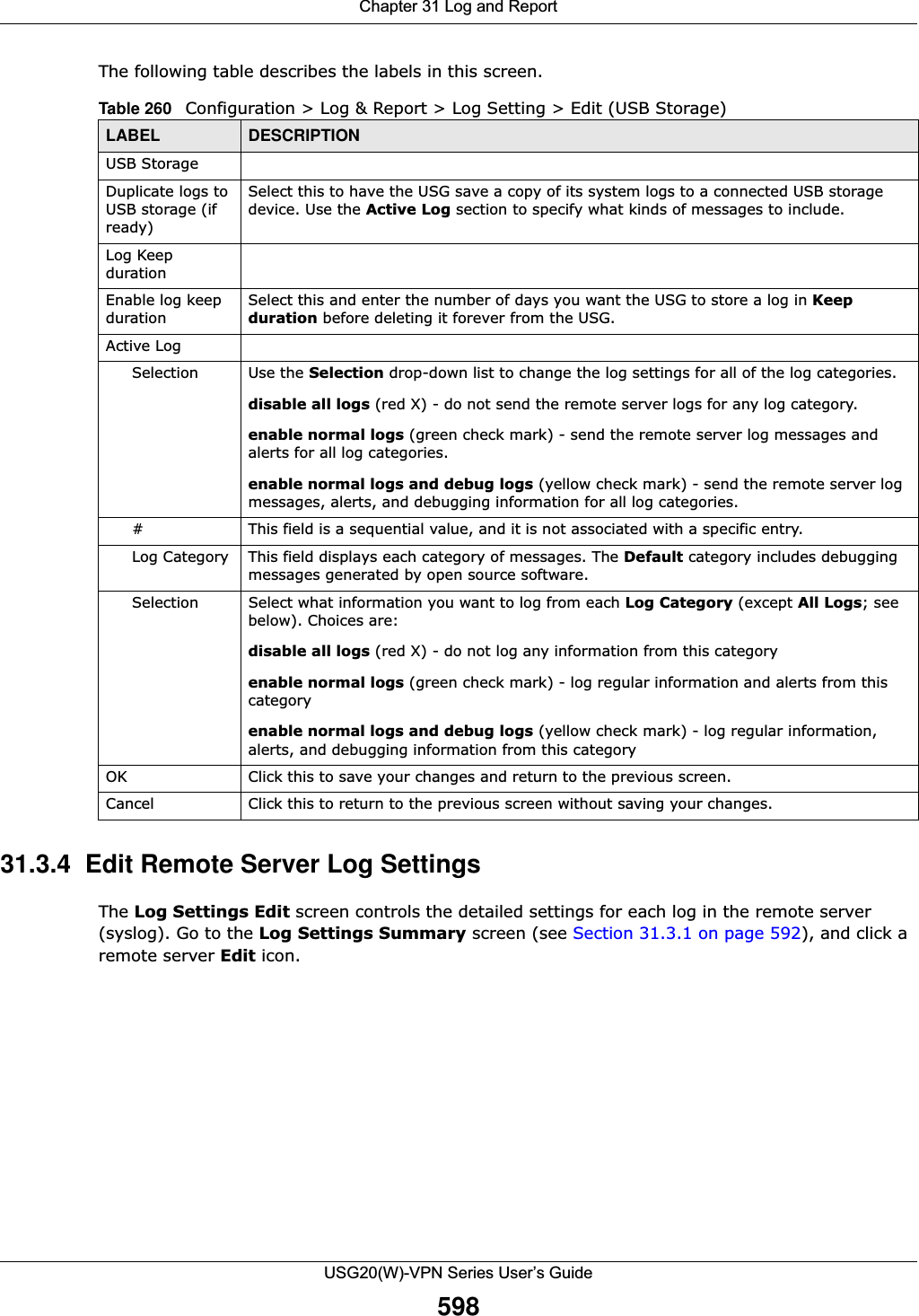
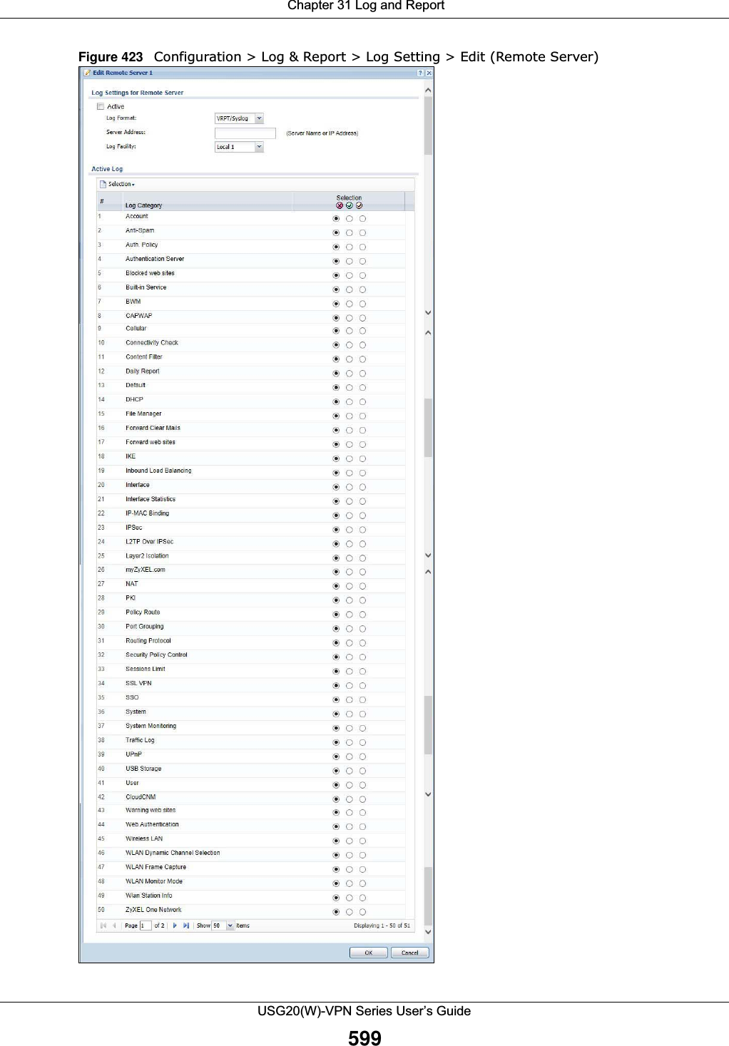
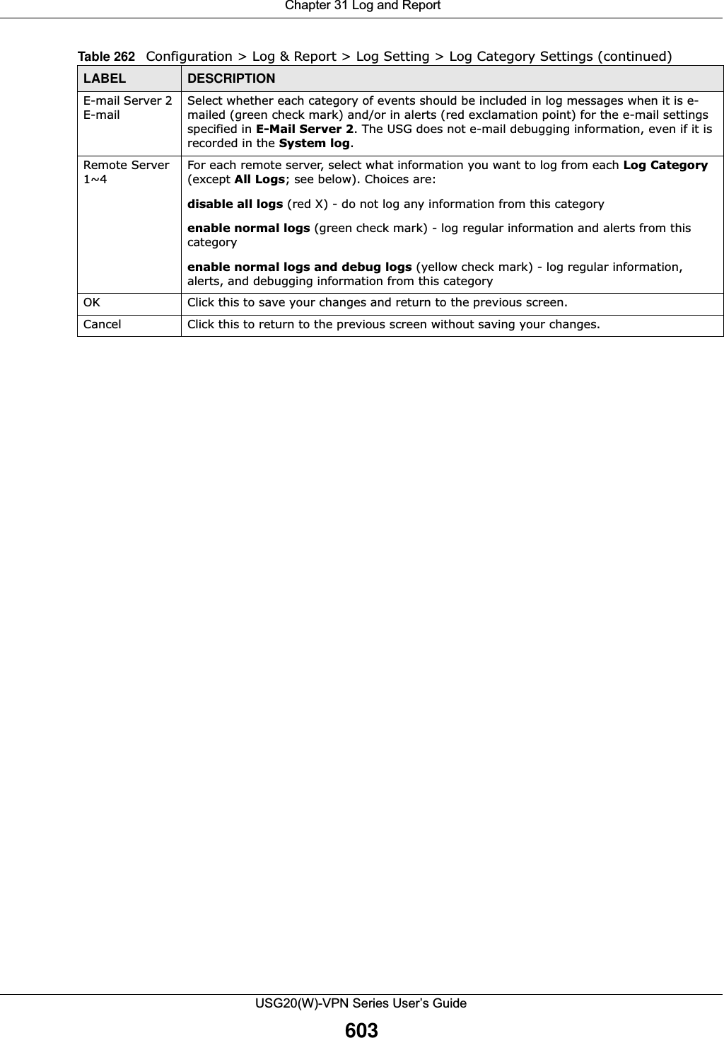
![Chapter 31 Log and ReportUSG20(W)-VPN Series User’s Guide59631.3.3 Edit Log on USB Storage Setting The Edit Log on USB Storage Setting screen controls the detailed settings for saving logs to a connected USB storage device. Go to the Log Setting Summary screen (see Section 31.3.1 on page 592), and click the USB storage Edit icon. E-mail Server 2 Use the E-Mail Server 2 drop-down list to change the settings for e-mailing logs to e-mail server 2 for all log categories.Using the System Log drop-down list to disable all logs overrides your e-mail server 2 settings.enable normal logs (green check mark) - e-mail log messages for all categories to e-mail server 2.enable alert logs (red exclamation point) - e-mail alerts for all categories to e-mail server 2.# This field is a sequential value, and it is not associated with a specific address.Log Category This field displays each category of messages. It is the same value used in the Display and Category fields in the View Log tab. The Default category includes debugging messages generated by open source software.System log Select which events you want to log by Log Category. There are three choices:disable all logs (red X) - do not log any information from this categoryenable normal logs (green check mark) - create log messages and alerts from this categoryenable normal logs and debug logs (yellow check mark) - create log messages, alerts, and debugging information from this category; the USG does not e-mail debugging information, however, even if this setting is selected.E-mail Server 1 Select whether each category of events should be included in the log messages when it is e-mailed (green check mark) and/or in alerts (red exclamation point) for the e-mail settings specified in E-Mail Server 1. The USG does not e-mail debugging information, even if it is recorded in the System log.E-mail Server 2 Select whether each category of events should be included in log messages when it is e-mailed (green check mark) and/or in alerts (red exclamation point) for the e-mail settings specified in E-Mail Server 2. The USG does not e-mail debugging information, even if it is recorded in the System log.Log ConsolidationActive Select this to activate log consolidation. Log consolidation aggregates multiple log messages that arrive within the specified Log Consolidation Interval. In the View Log tab, the text “[count=x]”, where x is the number of original log messages, is appended at the end of the Message field, when multiple log messages were aggregated.Log Consolidation Interval Type how often, in seconds, to consolidate log information. If the same log message appears multiple times, it is aggregated into one log message with the text “[count=x]”, where x is the number of original log messages, appended at the end of the Message field.OK Click this to save your changes and return to the previous screen.Cancel Click this to return to the previous screen without saving your changes.Table 259 Configuration > Log & Report > Log Setting > Edit (System Log) (continued)LABEL DESCRIPTION](https://usermanual.wiki/ZyXEL-Communications/USG20W-VPN.Users-Manual-Part-5/User-Guide-2904717-Page-60.png)

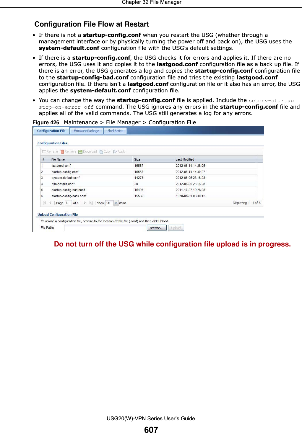
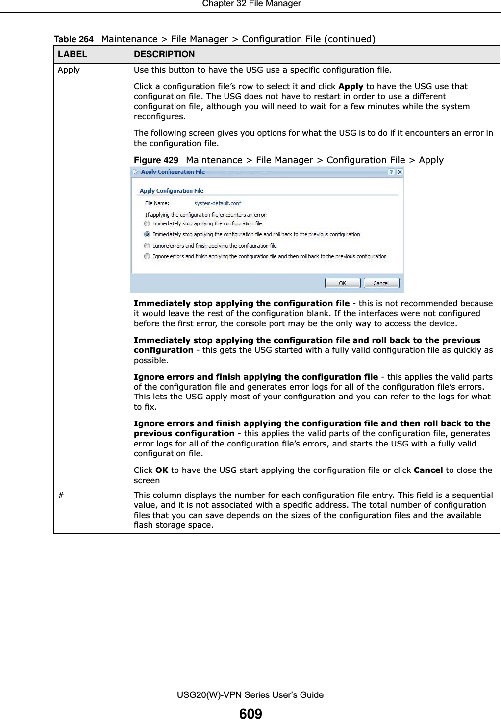
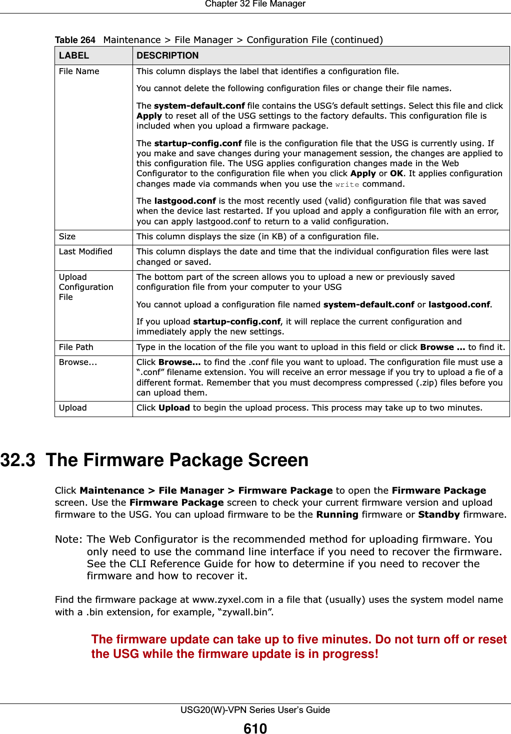
![Chapter 32 File ManagerUSG20(W)-VPN Series User’s Guide608The following table describes the labels in this screen. Table 264 Maintenance > File Manager > Configuration FileLABEL DESCRIPTIONRename Use this button to change the label of a configuration file on the USG. You can only rename manually saved configuration files. You cannot rename the lastgood.conf, system-default.conf and startup-config.conf files. You cannot rename a configuration file to the name of another configuration file in the USG. Click a configuration file’s row to select it and click Rename to open the Rename File screen. Figure 427 Maintenance > File Manager > Configuration File > Rename Specify the new name for the configuration file. Use up to 25 characters (including a-zA-Z0-9;‘~!@#$%^&()_+[]{}’,.=-). Click OK to save the duplicate or click Cancel to close the screen without saving a duplicate of the configuration file.Remove Click a configuration file’s row to select it and click Remove to delete it from the USG. You can only delete manually saved configuration files. You cannot delete the system-default.conf, startup-config.conf and lastgood.conf files.A pop-up window asks you to confirm that you want to delete the configuration file. Click OK to delete the configuration file or click Cancel to close the screen without deleting the configuration file.Download Click a configuration file’s row to select it and click Download to save the configuration to your computer.Copy Use this button to save a duplicate of a configuration file on the USG. Click a configuration file’s row to select it and click Copy to open the Copy File screen. Figure 428 Maintenance > File Manager > Configuration File > CopySpecify a name for the duplicate configuration file. Use up to 25 characters (including a-zA-Z0-9;‘~!@#$%^&()_+[]{}’,.=-). Click OK to save the duplicate or click Cancel to close the screen without saving a duplicate of the configuration file.](https://usermanual.wiki/ZyXEL-Communications/USG20W-VPN.Users-Manual-Part-5/User-Guide-2904717-Page-72.png)
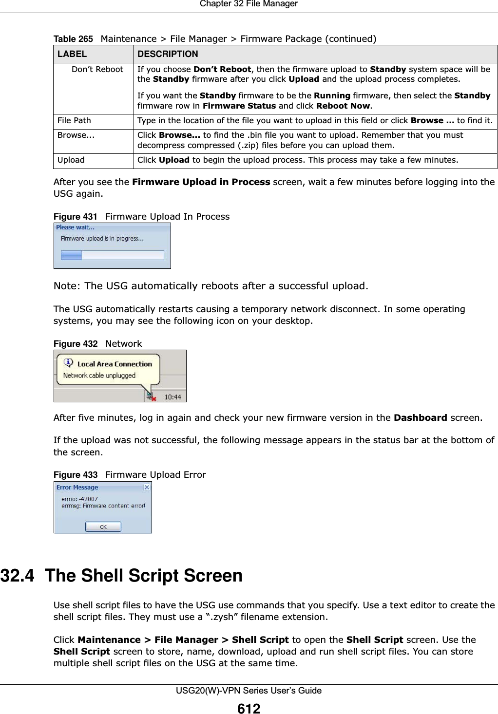
![Chapter 32 File ManagerUSG20(W)-VPN Series User’s Guide613Note: You should include write commands in your scripts. If you do not use the write command, the changes will be lost when the USG restarts. You could use multiple write commands in a long script.Figure 434 Maintenance > File Manager > Shell Script Each field is described in the following table. Table 266 Maintenance > File Manager > Shell ScriptLABEL DESCRIPTIONRename Use this button to change the label of a shell script file on the USG. You cannot rename a shell script to the name of another shell script in the USG. Click a shell script’s row to select it and click Rename to open the Rename File screen. Figure 435 Maintenance > File Manager > Shell Script > RenameSpecify the new name for the shell script file. Use up to 25 characters (including a-zA-Z0-9;‘~!@#$%^&()_+[]{}’,.=-). Click OK to save the duplicate or click Cancel to close the screen without saving a duplicate of the configuration file.Remove Click a shell script file’s row to select it and click Remove to delete the shell script file from the USG. A pop-up window asks you to confirm that you want to delete the shell script file. Click OK to delete the shell script file or click Cancel to close the screen without deleting the shell script file.Download Click a shell script file’s row to select it and click Download to save the configuration to your computer.](https://usermanual.wiki/ZyXEL-Communications/USG20W-VPN.Users-Manual-Part-5/User-Guide-2904717-Page-77.png)
![Chapter 32 File ManagerUSG20(W)-VPN Series User’s Guide614Copy Use this button to save a duplicate of a shell script file on the USG. Click a shell script file’s row to select it and click Copy to open the Copy File screen. Figure 436 Maintenance > File Manager > Shell Script > CopySpecify a name for the duplicate file. Use up to 25 characters (including a-zA-Z0-9;‘~!@#$%^&()_+[]{}’,.=-). Click OK to save the duplicate or click Cancel to close the screen without saving a duplicate of the configuration file.Apply Use this button to have the USG use a specific shell script file.Click a shell script file’s row to select it and click Apply to have the USG use that shell script file. You may need to wait awhile for the USG to finish applying the commands.#This column displays the number for each shell script file entry.File Name This column displays the label that identifies a shell script file.Size This column displays the size (in KB) of a shell script file.Last Modified This column displays the date and time that the individual shell script files were last changed or saved.Upload Shell ScriptThe bottom part of the screen allows you to upload a new or previously saved shell script file from your computer to your USG.File Path Type in the location of the file you want to upload in this field or click Browse ... to find it.Browse... Click Browse... to find the .zysh file you want to upload. Upload Click Upload to begin the upload process. This process may take up to several minutes.Table 266 Maintenance > File Manager > Shell Script (continued)LABEL DESCRIPTION](https://usermanual.wiki/ZyXEL-Communications/USG20W-VPN.Users-Manual-Part-5/User-Guide-2904717-Page-78.png)
![Chapter 33 DiagnosticsUSG20(W)-VPN Series User’s Guide617Figure 438 Maintenance > Diagnostics > Files The following table describes the labels in this screen. 33.3 The Packet Capture ScreenUse this screen to capture network traffic going through the USG’s interfaces. Studying these packet captures may help you identify network problems. Click Maintenance > Diagnostics > Packet Capture to open the packet capture screen.Note: New capture files overwrite existing files of the same name. Change the File Suffix field’s setting to avoid this.Table 268 Maintenance > Diagnostics > FilesLABEL DESCRIPTIONRemove Select files and click Remove to delete them from the USG. Use the [Shift] and/or [Ctrl] key to select multiple files. A pop-up window asks you to confirm that you want to delete.Download Click a file to select it and click Download to save it to your computer.#This column displays the number for each file entry. The total number of files that you can save depends on the file sizes and the available storage space.File Name This column displays the label that identifies the file. Size This column displays the size (in bytes) of a file.Last Modified This column displays the date and time that the individual files were saved.](https://usermanual.wiki/ZyXEL-Communications/USG20W-VPN.Users-Manual-Part-5/User-Guide-2904717-Page-81.png)
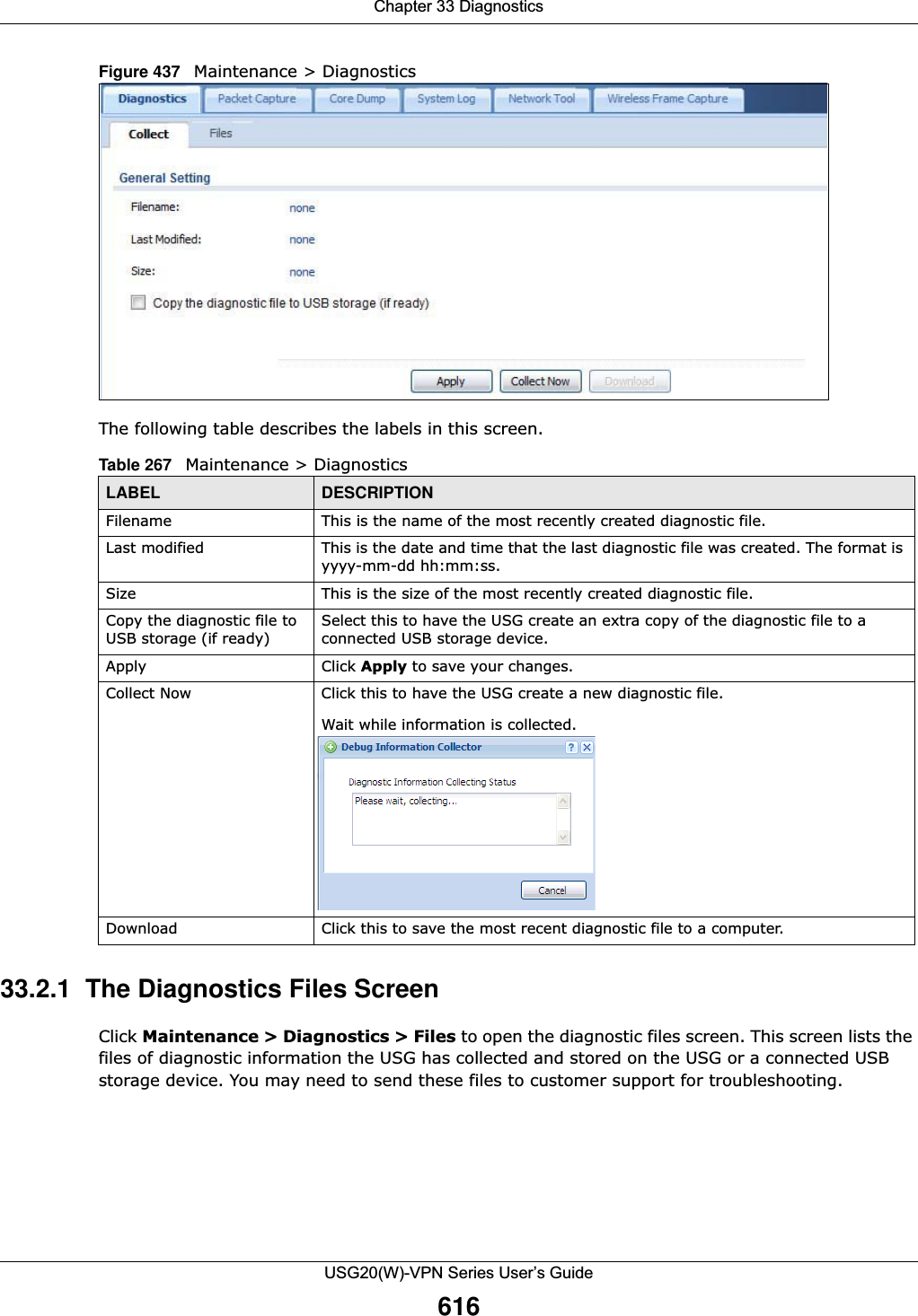
![Chapter 33 DiagnosticsUSG20(W)-VPN Series User’s Guide618Figure 439 Maintenance > Diagnostics > Packet Capture The following table describes the labels in this screen. Table 269 Maintenance > Diagnostics > Packet CaptureLABEL DESCRIPTIONInterfaces Enabled interfaces (except for virtual interfaces) appear under Available Interfaces. Select interfaces for which to capture packets and click the right arrow button to move them to the Capture Interfaces list. Use the [Shift] and/or [Ctrl] key to select multiple objects. FilterIP Version Select the version of IP for which to capture packets. Select any to capture packets for all IP versions.Protocol Type Select the protocol of traffic for which to capture packets. Select any to capture packets for all types of traffic.Host IP Select a host IP address object for which to capture packets. Select any to capture packets for all hosts. Select User Defined to be able to enter an IP address.Host Port This field is configurable when you set the IP Type to any, tcp, or udp. Specify the port number of traffic to capture.Misc settingContinuously capture and overwrite old onesSelect this to have the USG keep capturing traffic and overwriting old packet capture entries when the available storage space runs out.](https://usermanual.wiki/ZyXEL-Communications/USG20W-VPN.Users-Manual-Part-5/User-Guide-2904717-Page-82.png)
![Chapter 33 DiagnosticsUSG20(W)-VPN Series User’s Guide62033.3.1 The Packet Capture Files ScreenClick Maintenance > Diagnostics > Packet Capture > Files to open the packet capture files screen. This screen lists the files of packet captures stored on the USG or a connected USB storage device. You can download the files to your computer where you can study them using a packet analyzer (also known as a network or protocol analyzer) such as Wireshark.Figure 440 Maintenance > Diagnostics > Packet Capture > Files The following table describes the labels in this screen. 33.4 The Core Dump ScreenUse the Core Dump screen to have the USG save a process’s core dump to an attached USB storage device if the process terminates abnormally (crashes). You may need to send this file to customer support for troubleshooting.Click Maintenance > Diagnostics > Core Dump to open the following screen.Table 270 Maintenance > Diagnostics > Packet Capture > FilesLABEL DESCRIPTIONRemove Select files and click Remove to delete them from the USG or the connected USB storage device. Use the [Shift] and/or [Ctrl] key to select multiple files. A pop-up window asks you to confirm that you want to delete.Download Click a file to select it and click Download to save it to your computer.#This column displays the number for each packet capture file entry. The total number of packet capture files that you can save depends on the file sizes and the available flash storage space.File Name This column displays the label that identifies the file. The file name format is interface name-file suffix.cap. Size This column displays the size (in bytes) of a configuration file.Last Modified This column displays the date and time that the individual files were saved.](https://usermanual.wiki/ZyXEL-Communications/USG20W-VPN.Users-Manual-Part-5/User-Guide-2904717-Page-84.png)
![Chapter 33 DiagnosticsUSG20(W)-VPN Series User’s Guide621Figure 441 Maintenance > Diagnostics > Core DumpThe following table describes the labels in this screen. 33.4.1 The Core Dump Files Screen Click Maintenance > Diagnostics > Core Dump > Files to open the core dump files screen. This screen lists the core dump files stored on the USG or a connected USB storage device. You may need to send these files to customer support for troubleshooting.Figure 442 Maintenance > Diagnostics > Core Dump > Files The following table describes the labels in this screen. Table 271 Maintenance > Diagnostics > Core DumpLABEL DESCRIPTIONSave core dump to USB storage (if ready)Select this to have the USG save a process’s core dump to an attached USB storage device if the process terminates abnormally (crashes). If you clear this option the USG only saves Apply Click Apply to save the changes.Reset Click Reset to return the screen to its last-saved settings.Table 272 Maintenance > Diagnostics > Core Dump > FilesLABEL DESCRIPTIONRemove Select files and click Remove to delete them from the USG. Use the [Shift] and/or [Ctrl] key to select multiple files. A pop-up window asks you to confirm that you want to delete.Download Click a file to select it and click Download to save it to your computer.#This column displays the number for each core dump file entry. The total number of core dump files that you can save depends on the file sizes and the available flash storage space.](https://usermanual.wiki/ZyXEL-Communications/USG20W-VPN.Users-Manual-Part-5/User-Guide-2904717-Page-85.png)
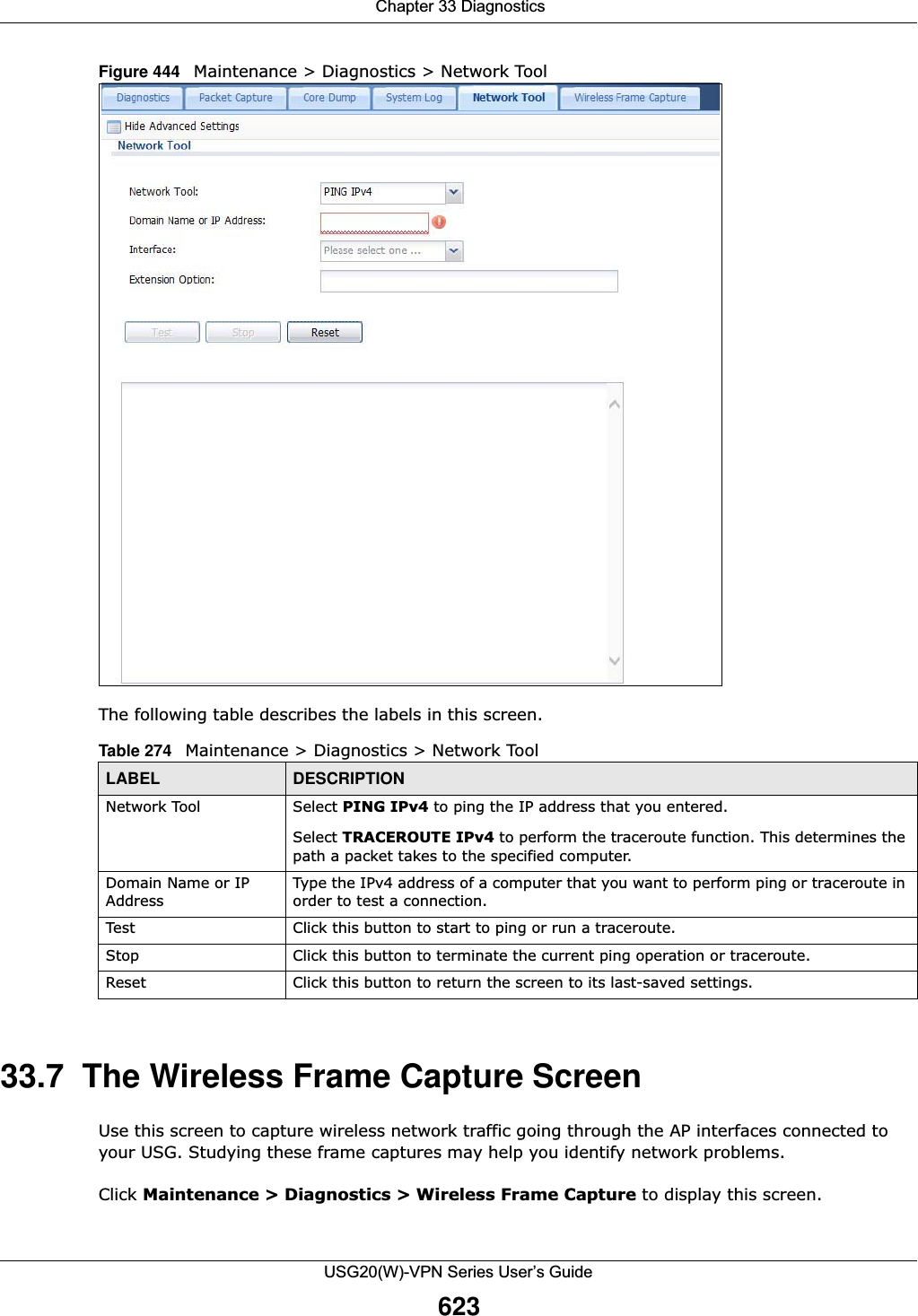
![Chapter 33 DiagnosticsUSG20(W)-VPN Series User’s Guide62233.5 The System Log ScreenClick Maintenance > Diagnostics > System Log to open the system log files screen. This screen lists the files of system logs stored on a connected USB storage device. The files are in comma separated value (csv) format. You can download them to your computer and open them in a tool like Microsoft’s Excel.Figure 443 Maintenance > Diagnostics > System Log The following table describes the labels in this screen. 33.6 The Network Tool ScreenUse this screen to ping or traceroute an IP address. Click Maintenance > Diagnostics > Network Tool to display this screen. File Name This column displays the label that identifies the file. Size This column displays the size (in bytes) of a file.Last Modified This column displays the date and time that the individual files were saved.Table 272 Maintenance > Diagnostics > Core Dump > Files (continued)LABEL DESCRIPTIONTable 273 Maintenance > Diagnostics > System Log LABEL DESCRIPTIONRemove Select files and click Remove to delete them from the USG. Use the [Shift] and/or [Ctrl] key to select multiple files. A pop-up window asks you to confirm that you want to delete.Download Click a file to select it and click Download to save it to your computer.#This column displays the number for each file entry. The total number of files that you can save depends on the file sizes and the available storage space.File Name This column displays the label that identifies the file. Size This column displays the size (in bytes) of a file.Last Modified This column displays the date and time that the individual files were saved.](https://usermanual.wiki/ZyXEL-Communications/USG20W-VPN.Users-Manual-Part-5/User-Guide-2904717-Page-86.png)
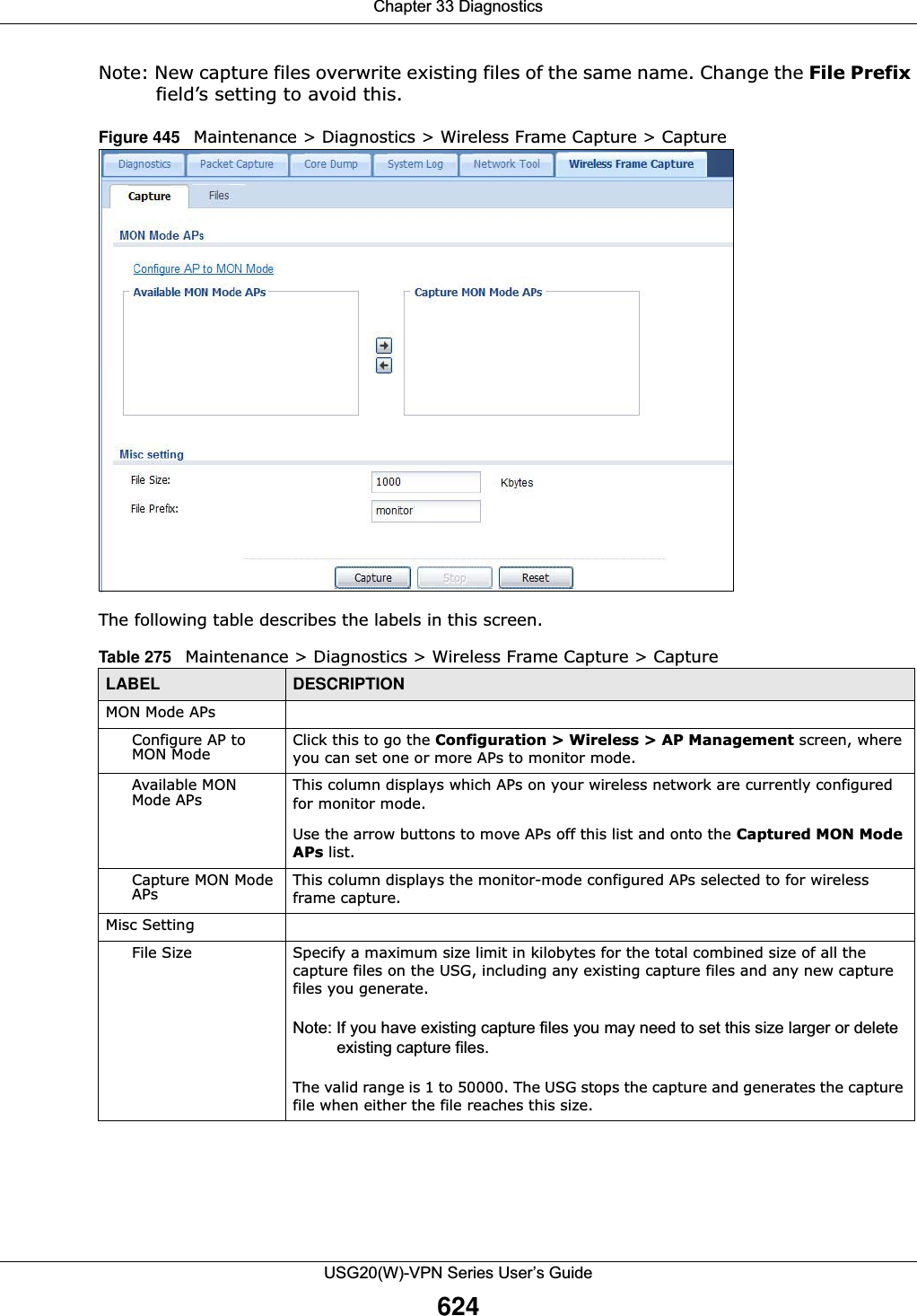
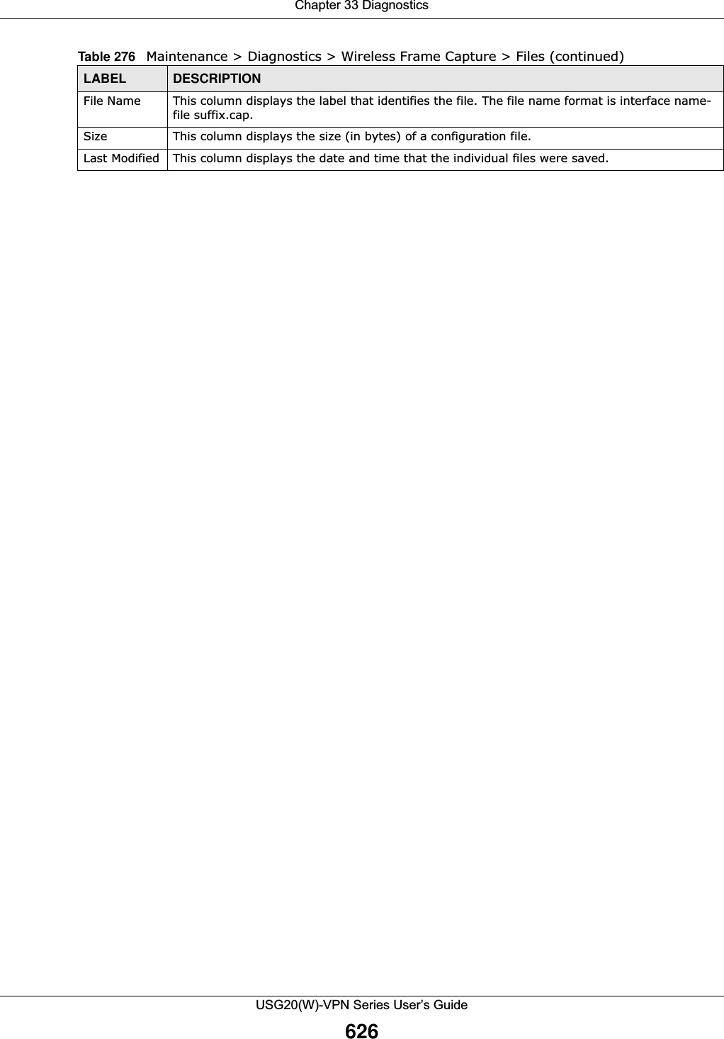
![Chapter 33 DiagnosticsUSG20(W)-VPN Series User’s Guide62533.7.1 The Wireless Frame Capture Files Screen Click Maintenance > Diagnostics > Wireless Frame Capture > Files to open this screen. This screen lists the files of wireless frame captures the USG has performed. You can download the files to your computer where you can study them using a packet analyzer (also known as a network or protocol analyzer) such as Wireshark.Figure 446 Maintenance > Diagnostics > Wireless Frame Capture > Files The following table describes the labels in this screen. File Prefix Specify text to add to the front of the file name in order to help you identify frame capture files.You can modify the prefix to also create new frame capture files each time you perform a frame capture operation. Doing this does no overwrite existing frame capture files.The file format is: [file prefix].cap. For example, “monitor.cap”.Capture Click this button to have the USG capture frames according to the settings configured in this screen. You can configure the USG while a frame capture is in progress although you cannot modify the frame capture settings.The USG’s throughput or performance may be affected while a frame capture is in progress.After the USG finishes the capture it saves a combined capture file for all APs. The total number of frame capture files that you can save depends on the file sizes and the available flash storage space. Once the flash storage space is full, adding more frame captures will fail.Stop Click this button to stop a currently running frame capture and generate a combined capture file for all APs. Reset Click this button to return the screen to its last-saved settings. Table 275 Maintenance > Diagnostics > Wireless Frame Capture > Capture (continued)LABEL DESCRIPTIONTable 276 Maintenance > Diagnostics > Wireless Frame Capture > FilesLABEL DESCRIPTIONRemove Select files and click Remove to delete them from the USG. Use the [Shift] and/or [Ctrl] key to select multiple files. A pop-up window asks you to confirm that you want to delete.Download Click a file to select it and click Download to save it to your computer.#This column displays the number for each packet capture file entry. The total number of packet capture files that you can save depends on the file sizes and the available flash storage space.](https://usermanual.wiki/ZyXEL-Communications/USG20W-VPN.Users-Manual-Part-5/User-Guide-2904717-Page-89.png)
![USG20(W)-VPN Series User’s Guide636CHAPTER 36TroubleshootingThis chapter offers some suggestions to solve problems you might encounter. • You can also refer to the logs (see Chapter 6 on page 100). • For the order in which the USG applies its features and checks, see Chapter 34 on page 627.None of the LEDs turn on.Make sure that you have the power cord connected to the USG and plugged in to an appropriate power source. Make sure you have the USG turned on. Check all cable connections.If the LEDs still do not turn on, you may have a hardware problem. In this case, you should contact your local vendor.Cannot access the USG from the LAN.• Check the cable connection between the USG and your computer or switch. • Ping the USG from a LAN computer. Make sure your computer’s Ethernet card is installed and functioning properly. Also make sure that its IP address is in the same subnet as the USG’s.• In the computer, click Start, (All) Programs, Accessories and then Command Prompt. In the Command Prompt window, type "ping" followed by the USG’s LAN IP address (192.168.1.1 is the default) and then press [ENTER]. The USG should reply.• If you’ve forgotten the USG’s password, use the RESET button. Press the button in for about 5 seconds (or until the PWR LED starts to blink), then release it. It returns the USG to the factory defaults (password is 1234, LAN IP address 192.168.1.1 etc.; see your User’s Guide for details).• If you’ve forgotten the USG’s IP address, you can use the commands through the console port to check it. Connect your computer to the CONSOLE port using a console cable. Your computer should have a terminal emulation communications program (such as HyperTerminal) set to VT100 terminal emulation, no parity, 8 data bits, 1 stop bit, no flow control and 115200 bps port speed. I cannot access the Internet.• Check the USG’s connection to the Ethernet jack with Internet access. Make sure the Internet gateway device (such as a DSL modem) is working properly. • Check the WAN interface's status in the Dashboard. Use the installation setup wizard again and make sure that you enter the correct settings. Use the same case as provided by your ISP.](https://usermanual.wiki/ZyXEL-Communications/USG20W-VPN.Users-Manual-Part-5/User-Guide-2904717-Page-100.png)