ZyXEL Communications USG20W-VPN VPN Firewall User Manual Book
ZyXEL Communications Corporation VPN Firewall Book
Contents
- 1. Users Manual Part 1
- 2. Users Manual Part 2
- 3. Users Manual Part 3
- 4. Users Manual Part 4
- 5. Users Manual Part 5
Users Manual Part 2
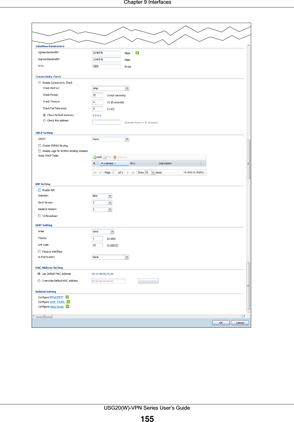
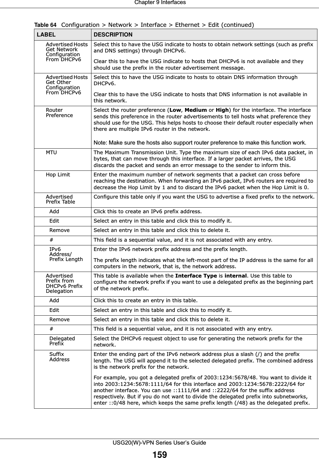
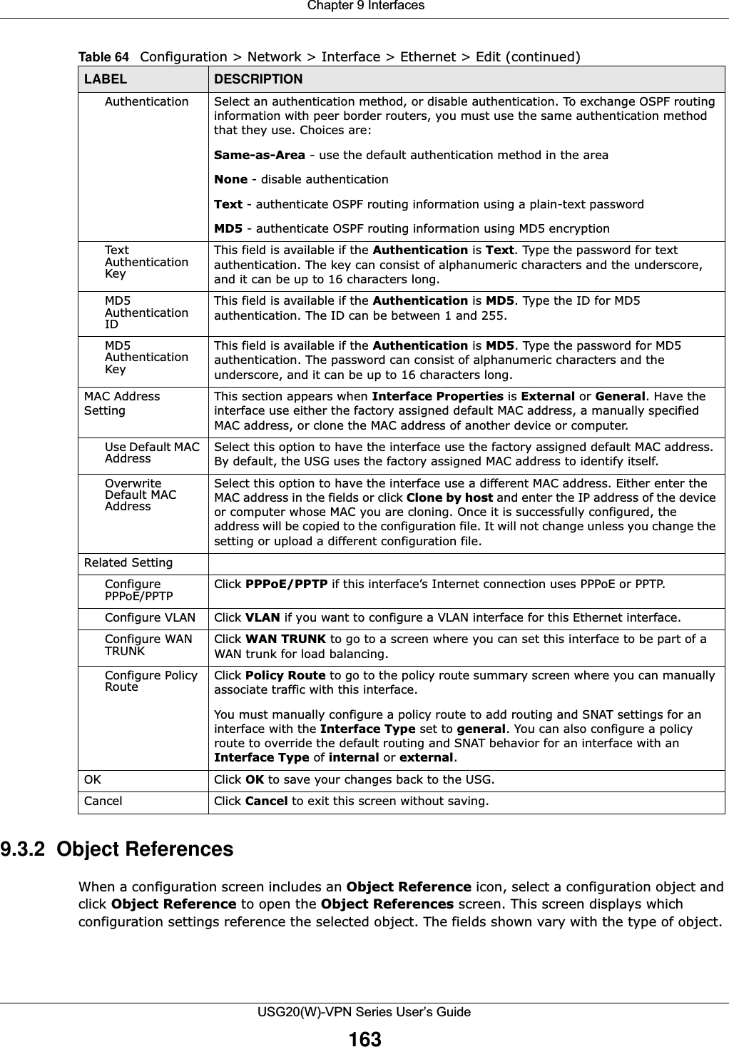
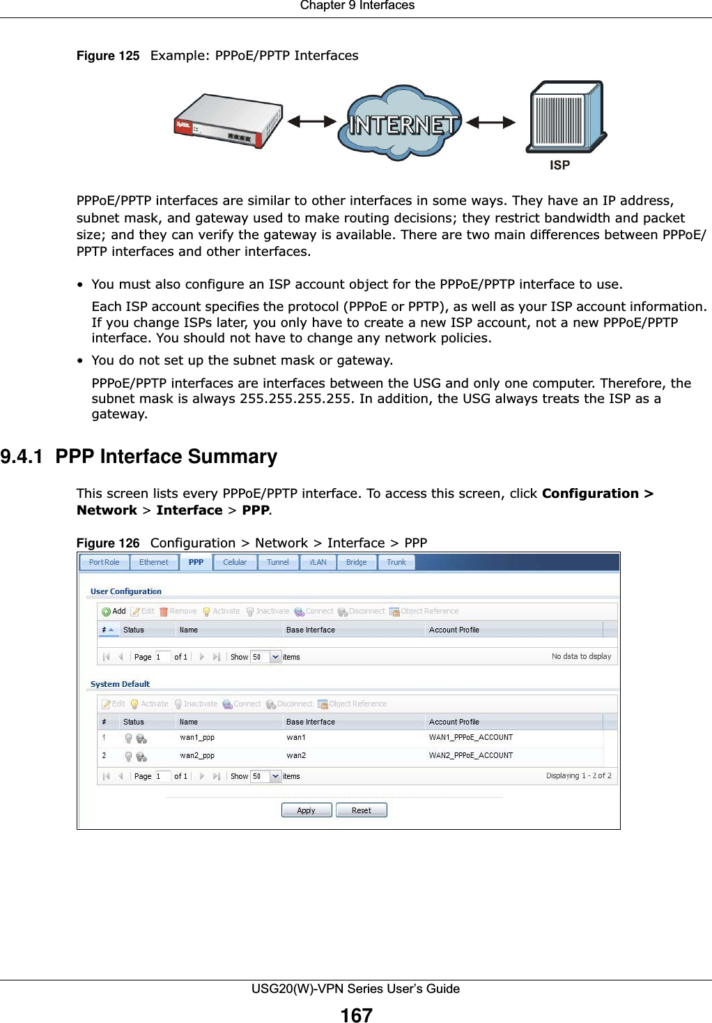
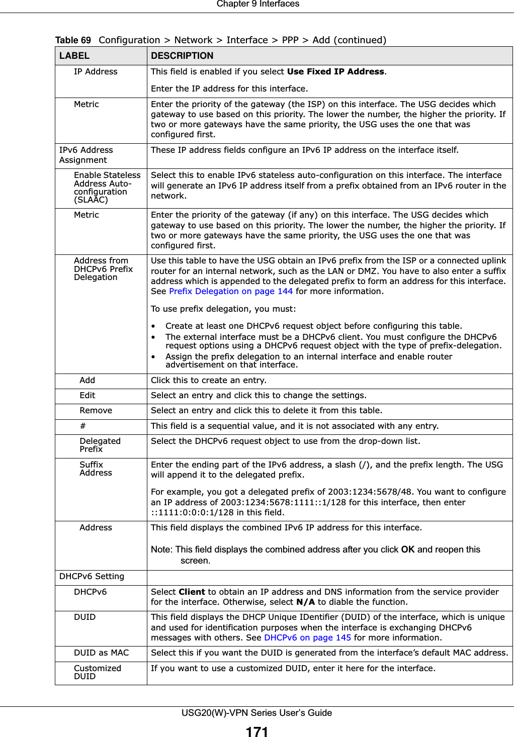
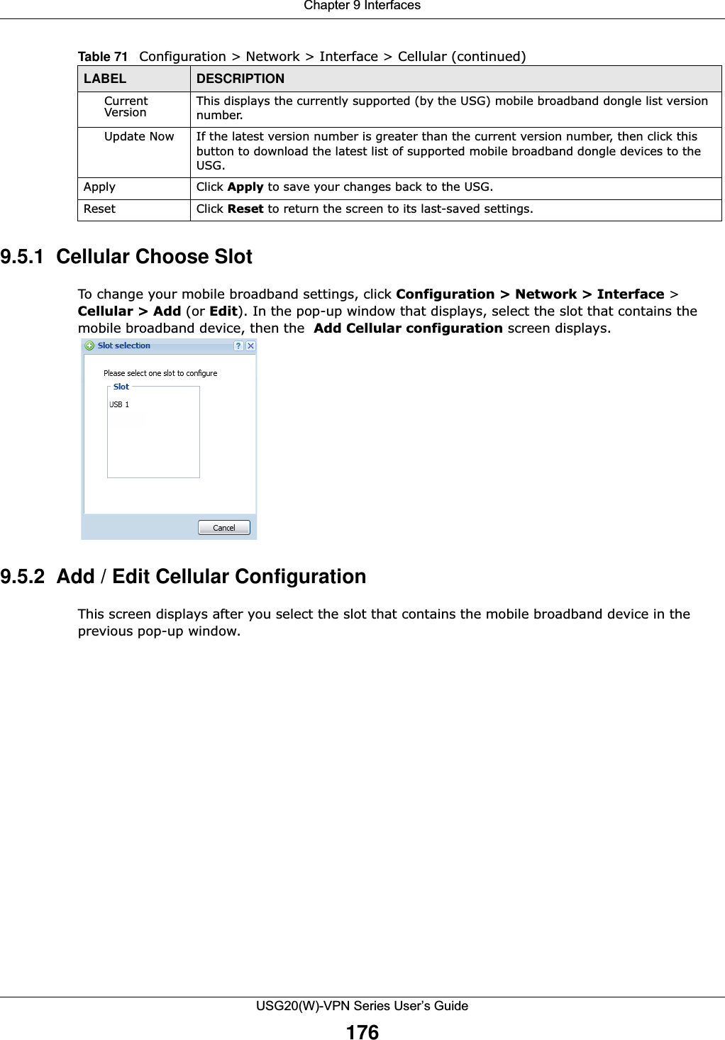
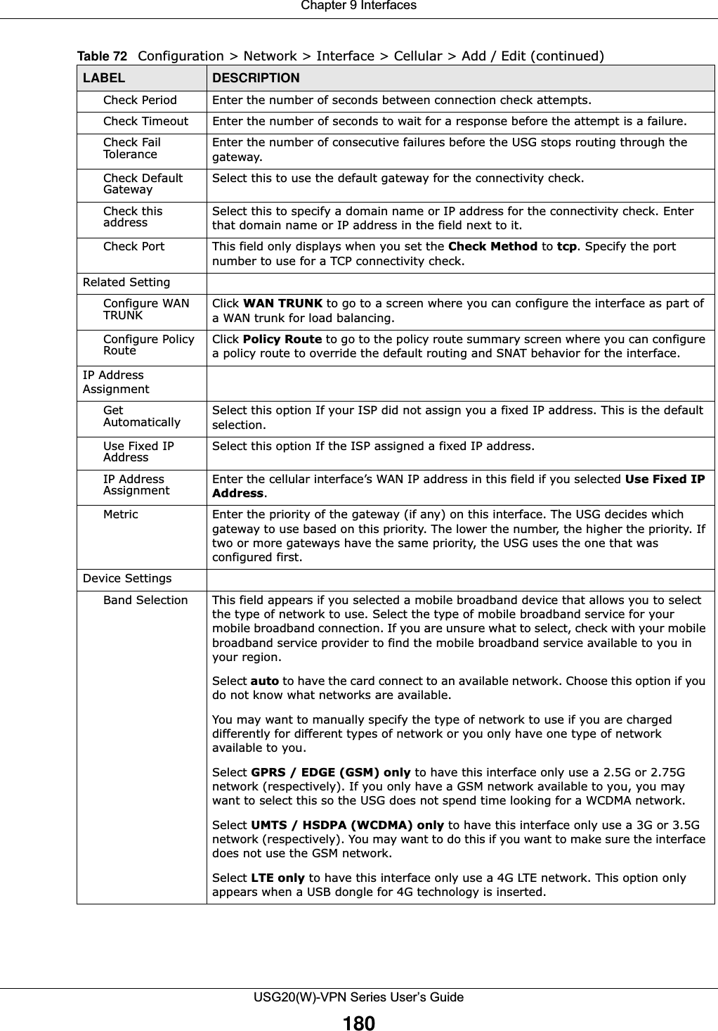
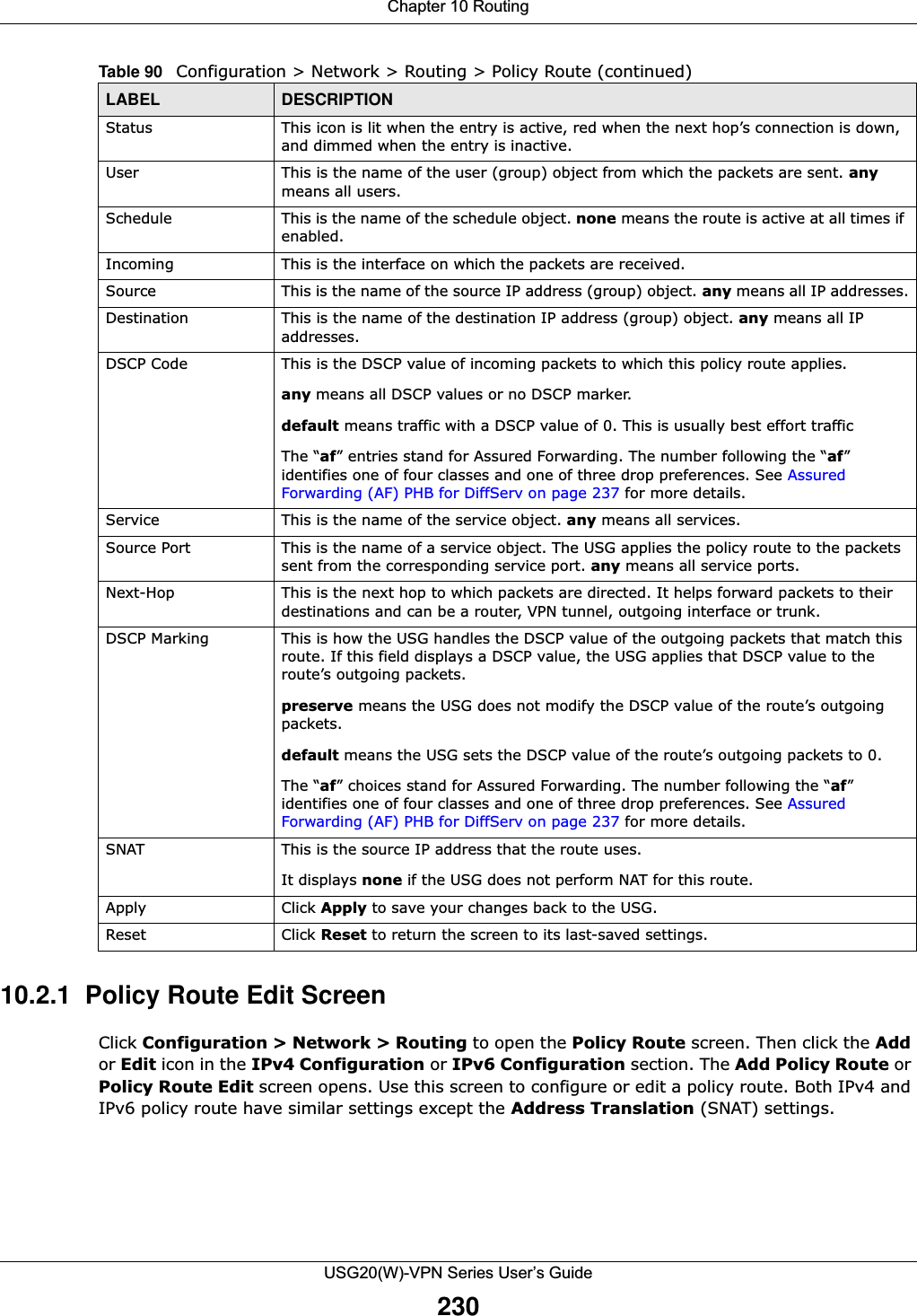
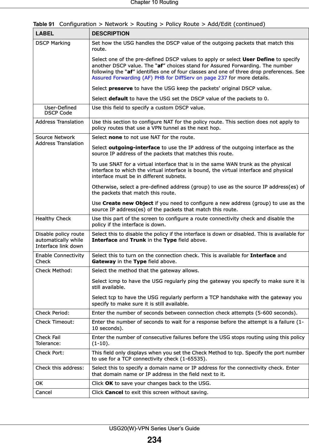
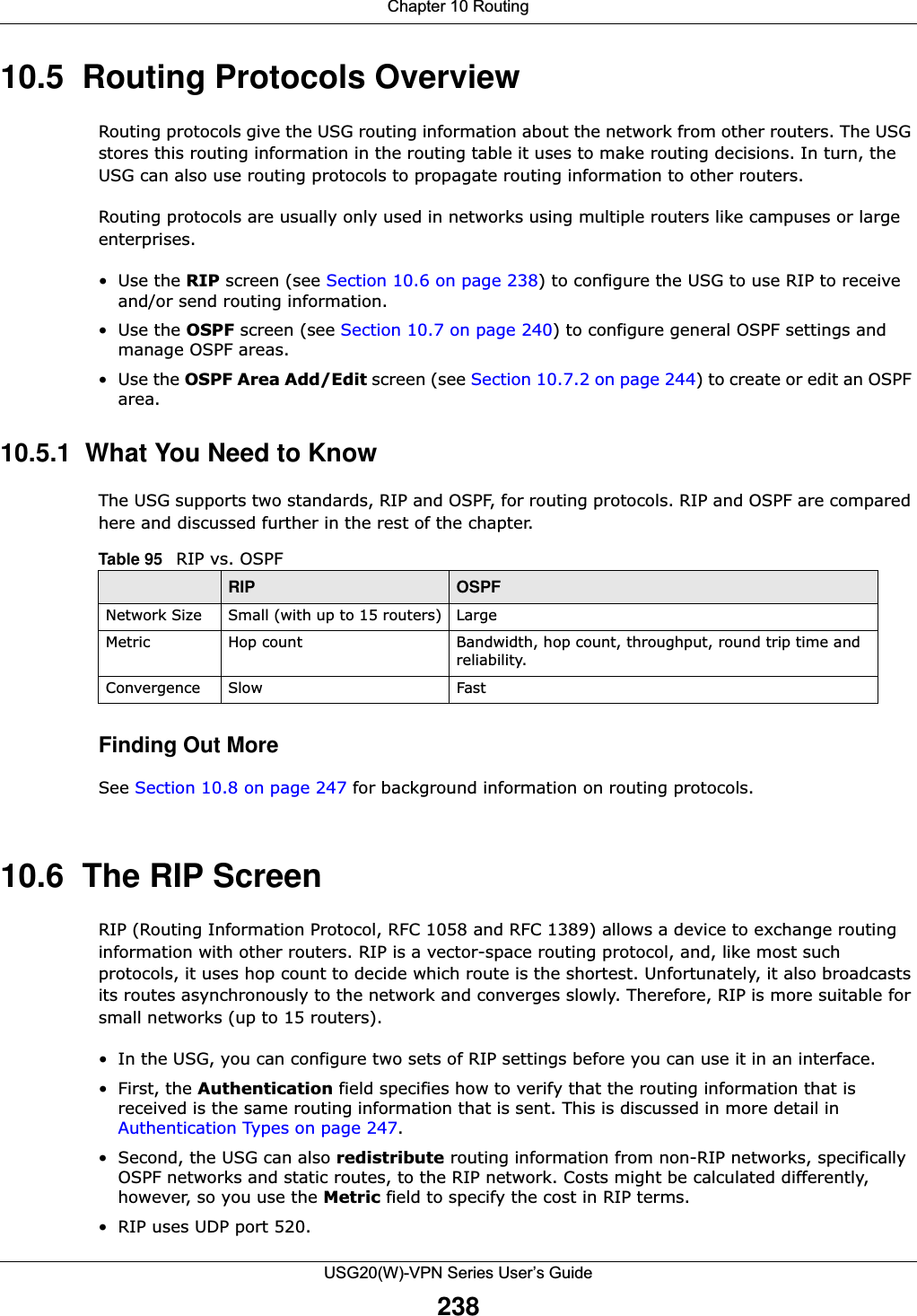
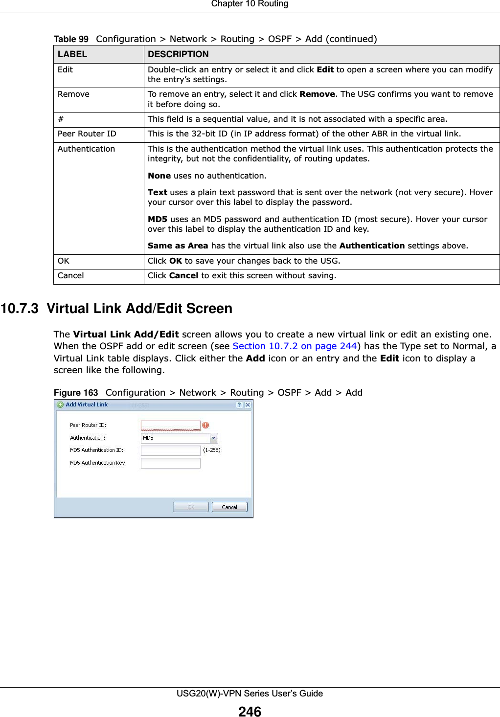
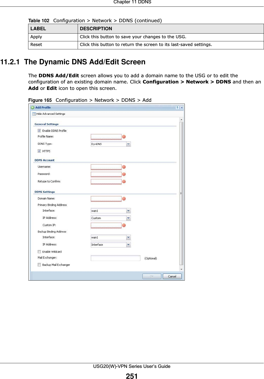
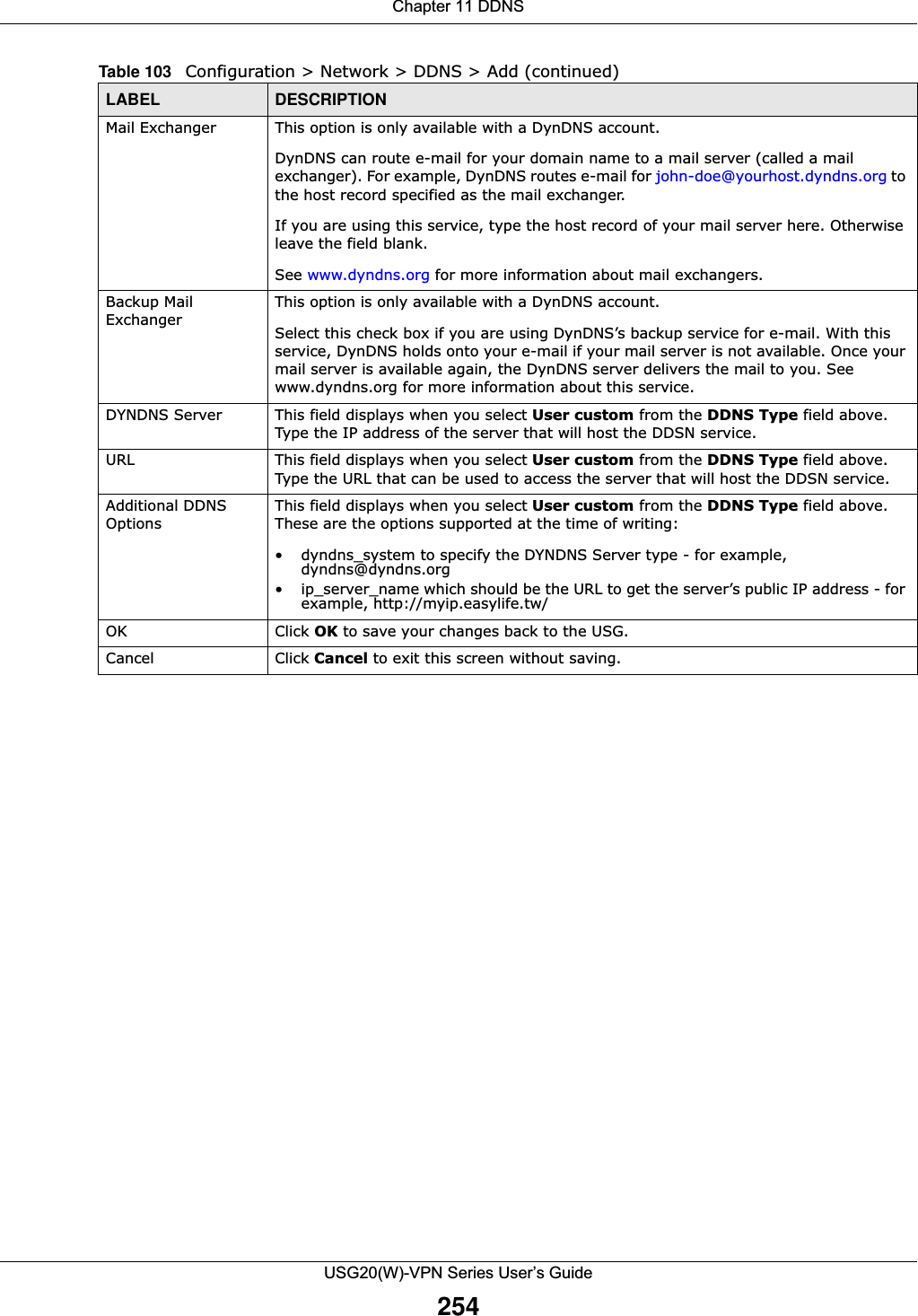
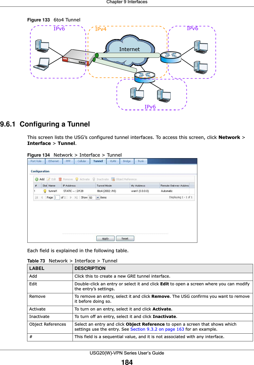
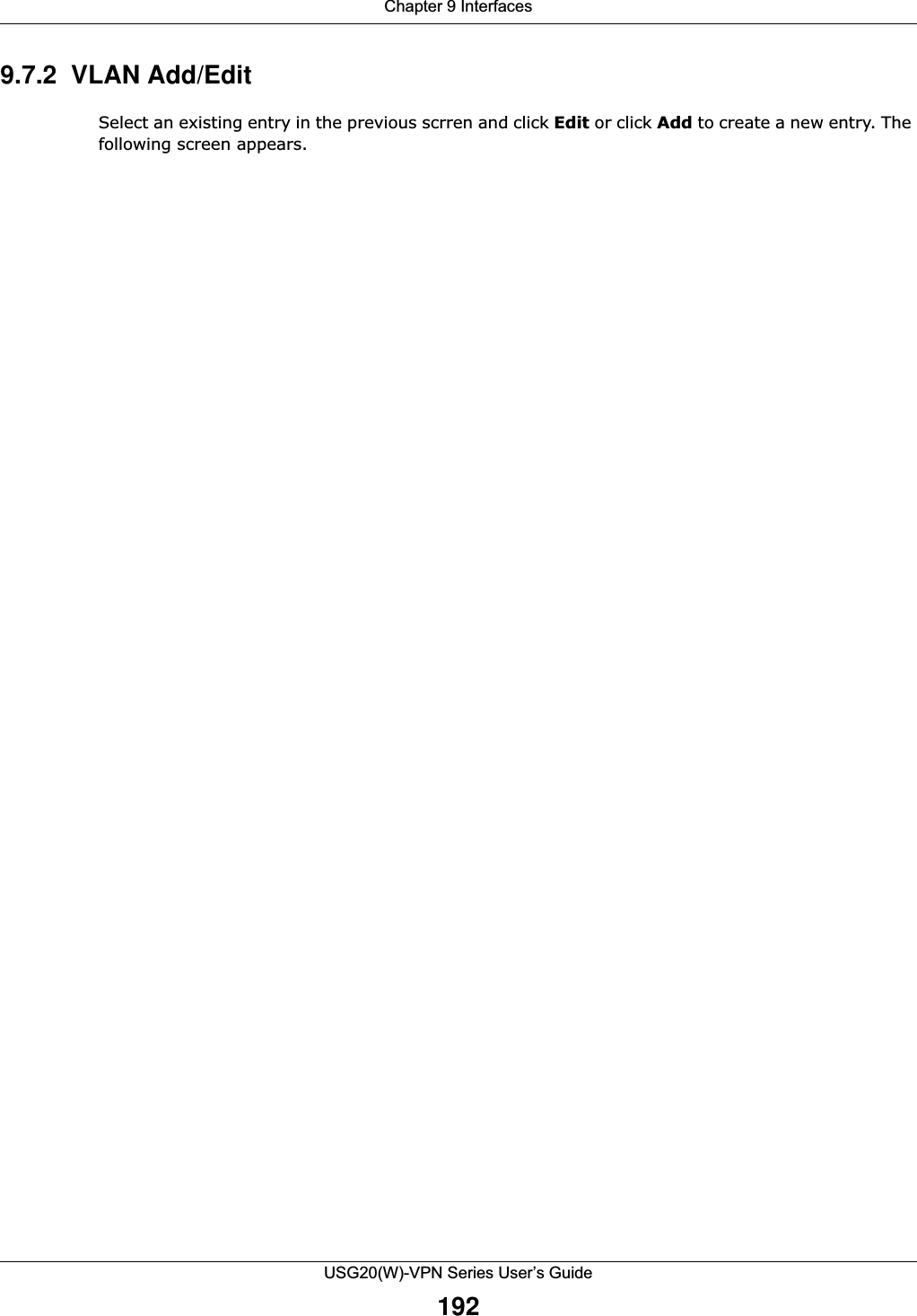
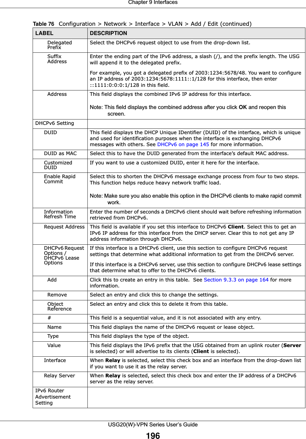
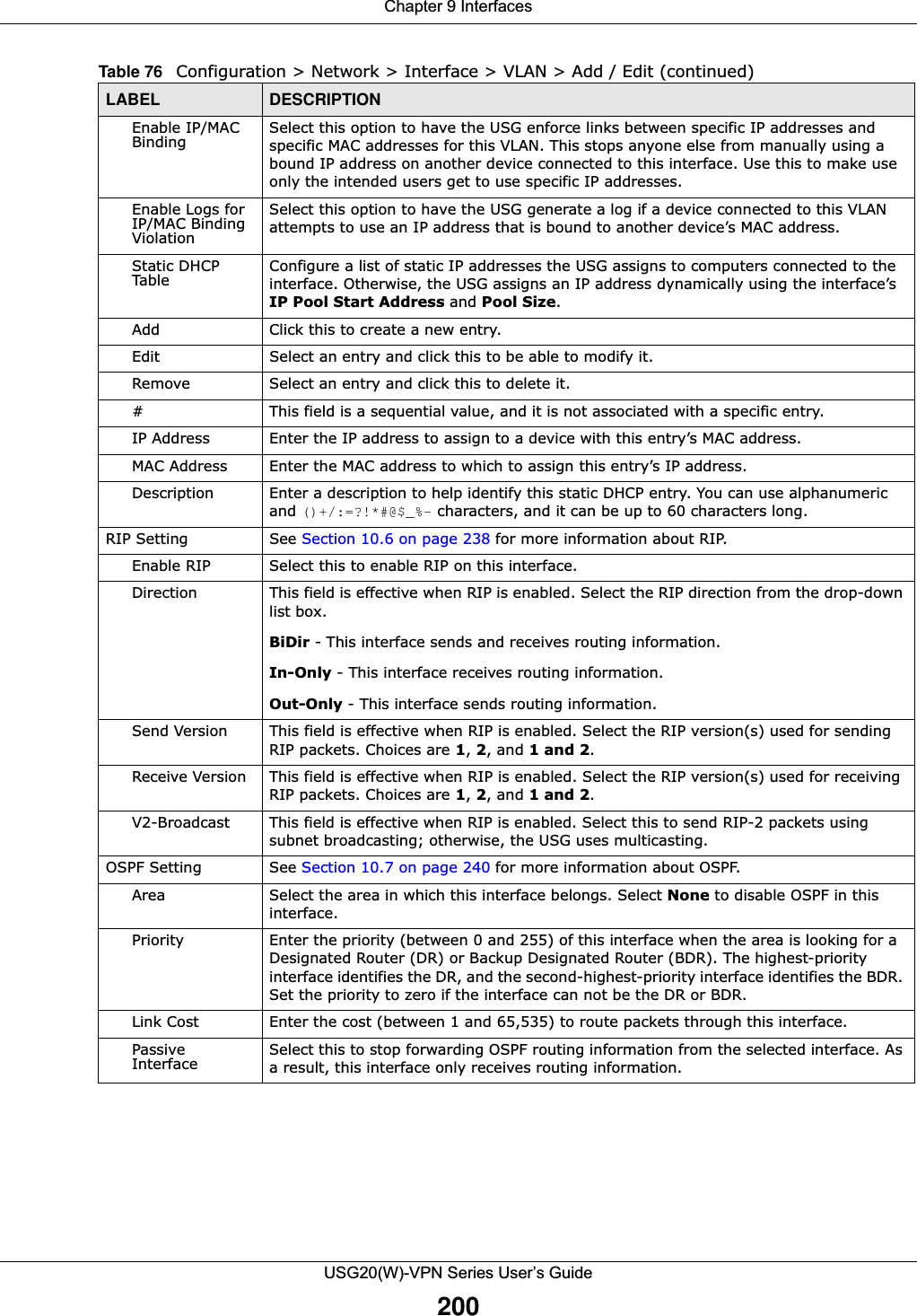
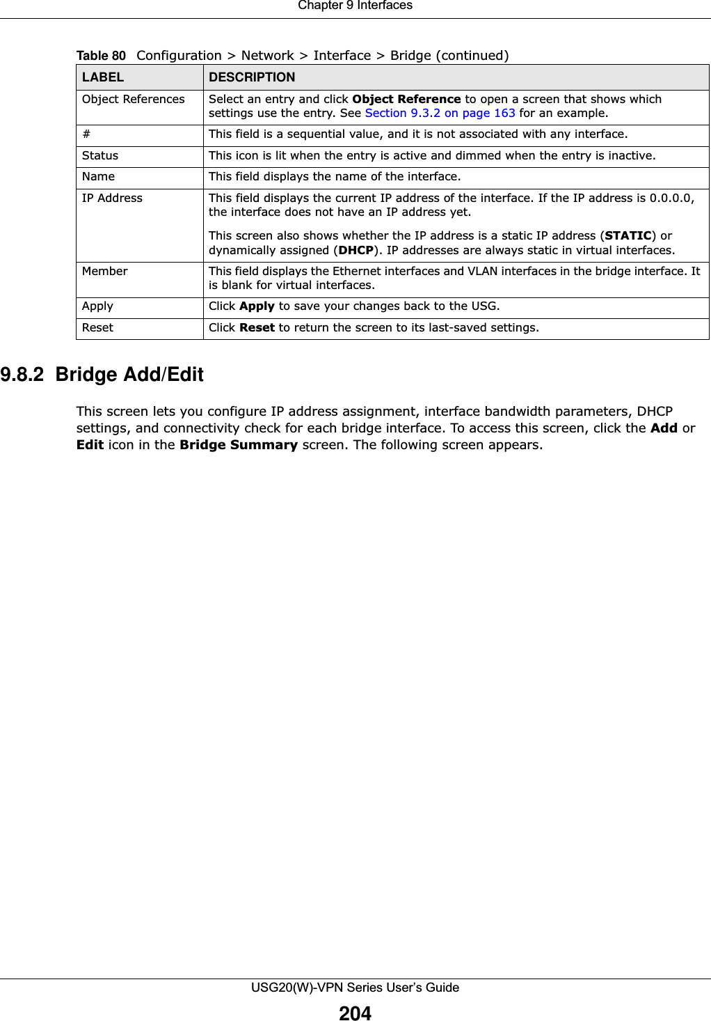
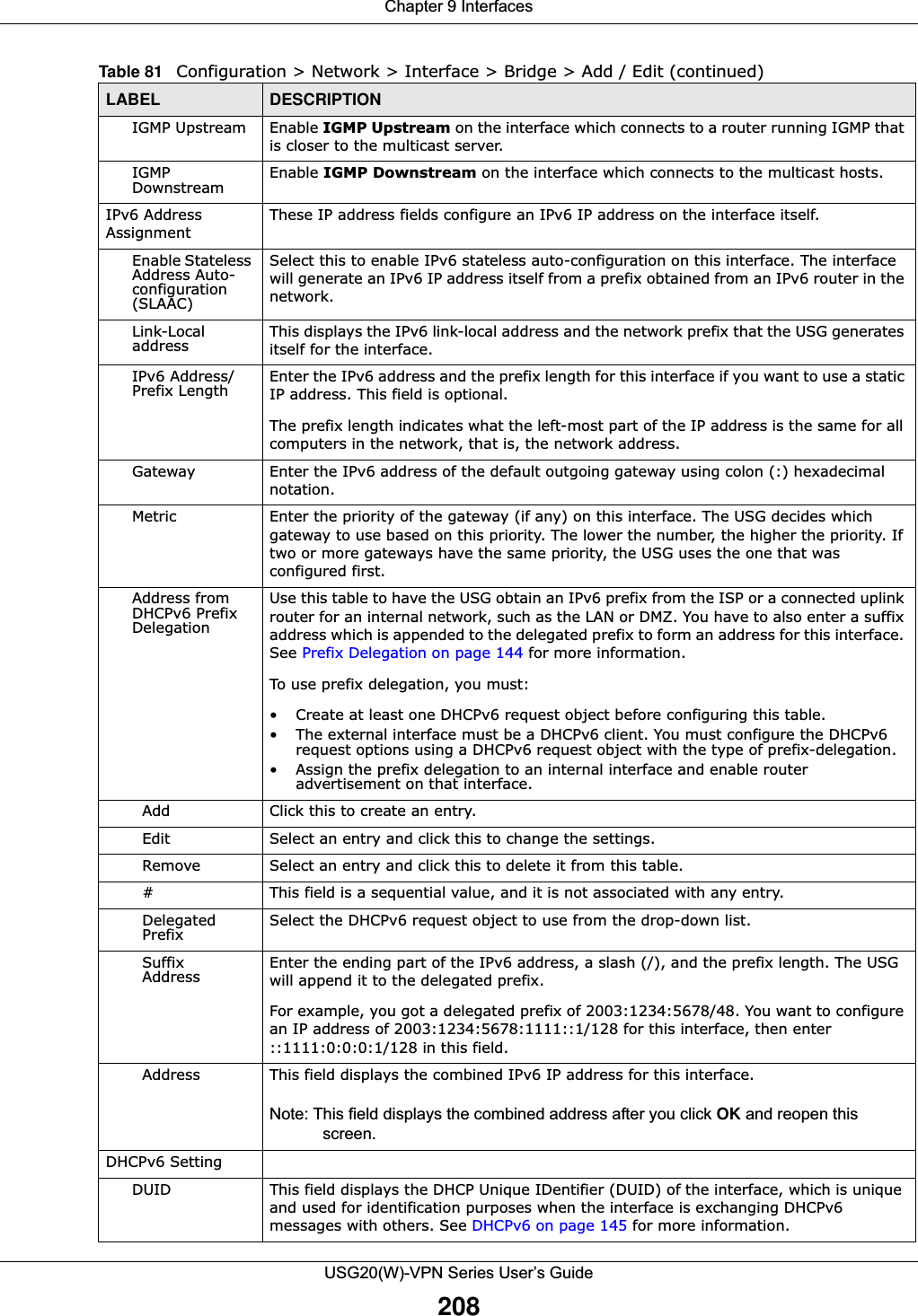
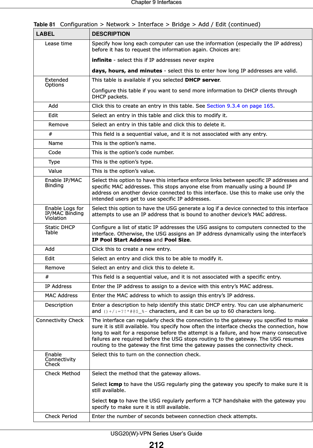
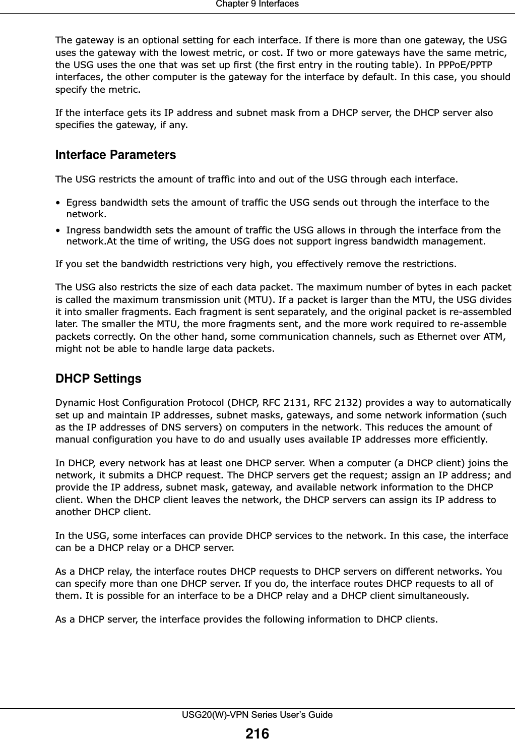
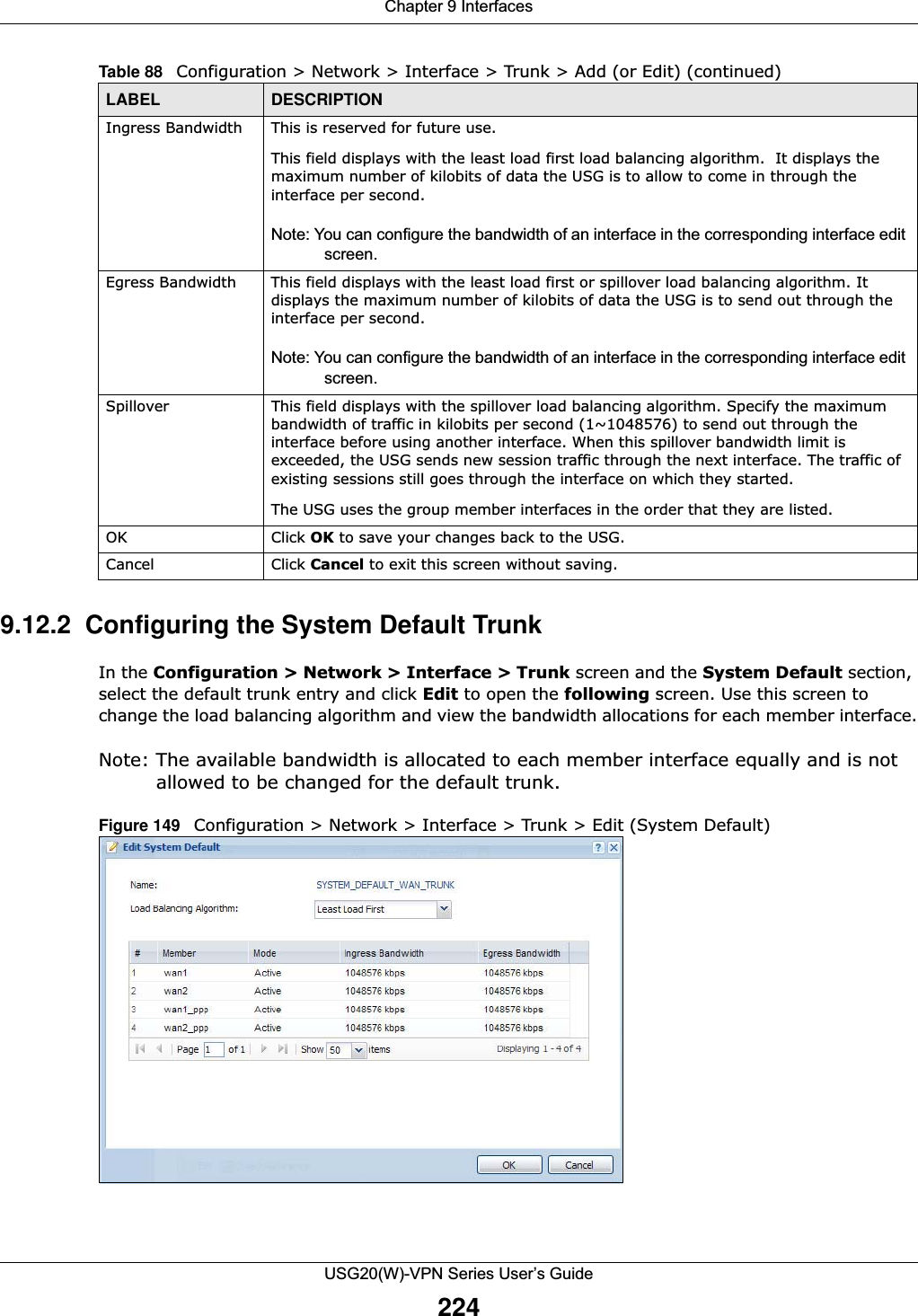
![Chapter 9 InterfacesUSG20(W)-VPN Series User’s Guide183IPv6-in-IPv4 TunnelingUse this mode on the WAN of the USG if • your USG has a public IPv4 IP address given from your ISP,and• you want to transmit your IPv6 packets to one and only one remote site whose LAN network is also an IPv6 network. With this mode, the USG encapsulates IPv6 packets within IPv4 packets across the Internet. You must know the WAN IP address of the remote gateway device. This mode is normally used for a site-to-site application such as two branch offices.Figure 132 IPv6-in-IPv4 Tunnel In the USG, you must also manually configure a policy route for an IPv6-in-IPv4 tunnel to make the tunnel work.6to4 TunnelingThis mode also enables IPv6 packets to cross IPv4 networks. Unlike IPv6-in-IPv4 tunneling, you do not need to configure a policy route for a 6to4 tunnel. Through your properly pre-configuring the destination router’s IP address in the IP address assignments to hosts, the USG can automatically forward 6to4 packets to the destination they want to go. A 6to4 relay router is required to route 6to4 packets to a native IPv6 network if the packet’s destination do not match your specified criteria.In this mode, the USG should get a public IPv4 address for the WAN. The USG adds an IPv4 IP header to an IPv6 packet when transmitting the packet to the Internet. In reverse, the USG removes the IPv4 header from an IPv6 packet when receiving it from the Internet. An IPv6 address using the 6to4 mode consists of an IPv4 address, the format is as the following:2002:[a public IPv4 address in hexadecimal]::/48For example, a public IPv4 address is 202.156.30.41. The converted hexadecimal IP string is ca.9c.1Ee.29. The IPv6 address prefix becomes 2002:ca9c:1e29::/48.IPv6 IPv4 IPv6 Internet](https://usermanual.wiki/ZyXEL-Communications/USG20W-VPN.Users-Manual-Part-2/User-Guide-2904714-Page-44.png)
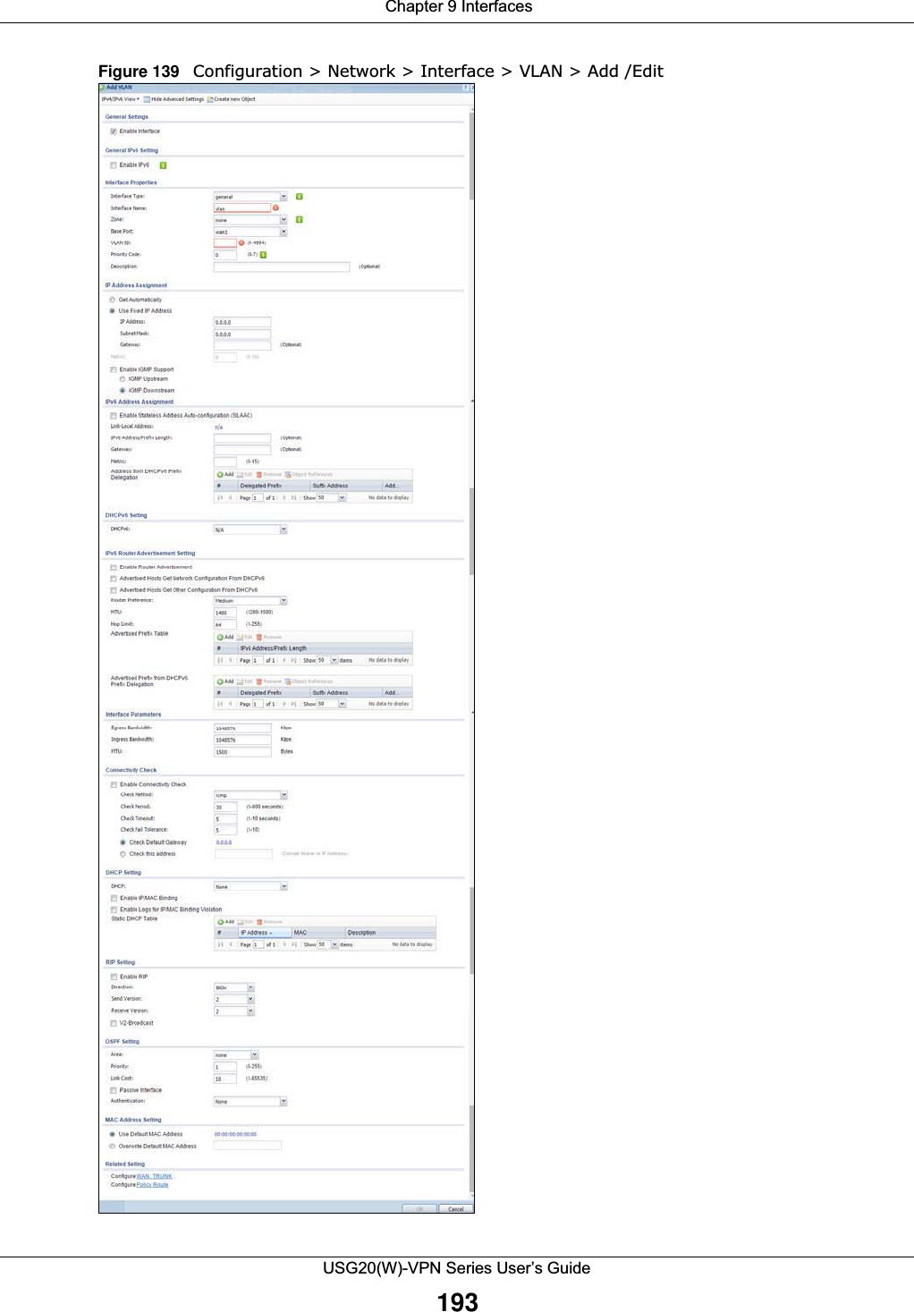
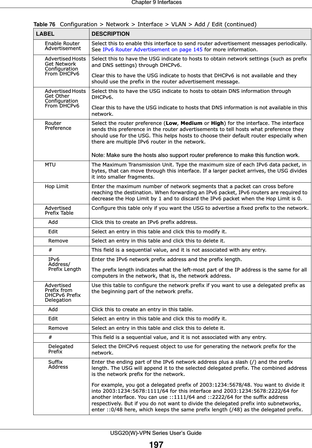
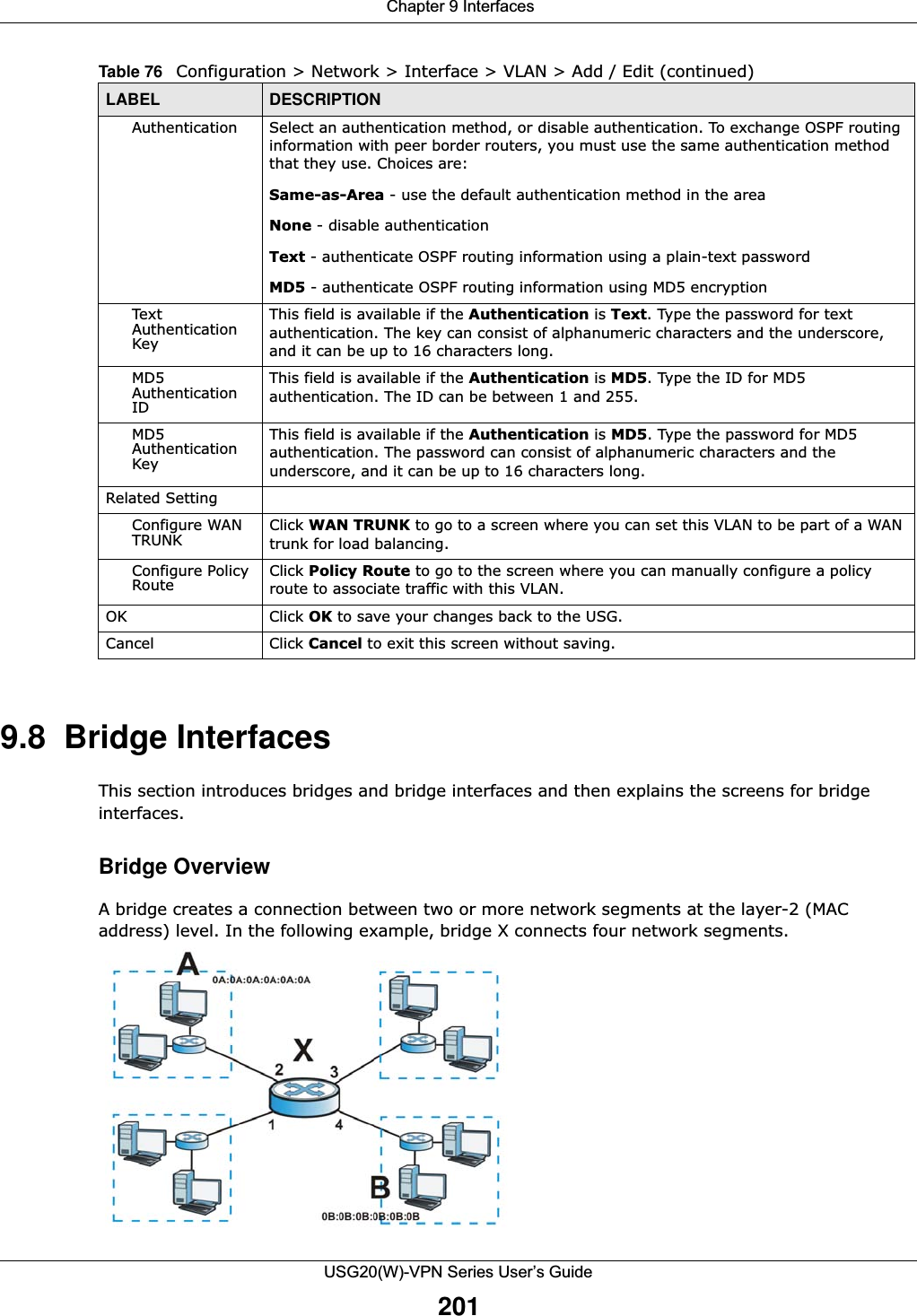
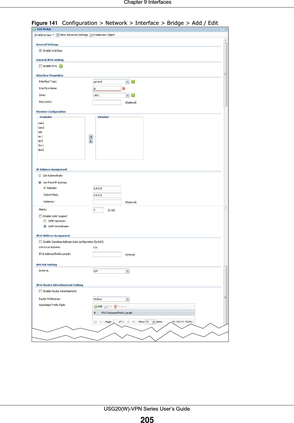
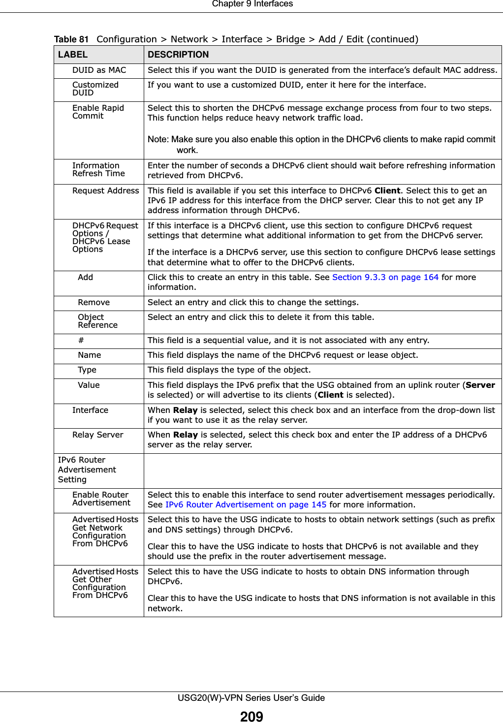
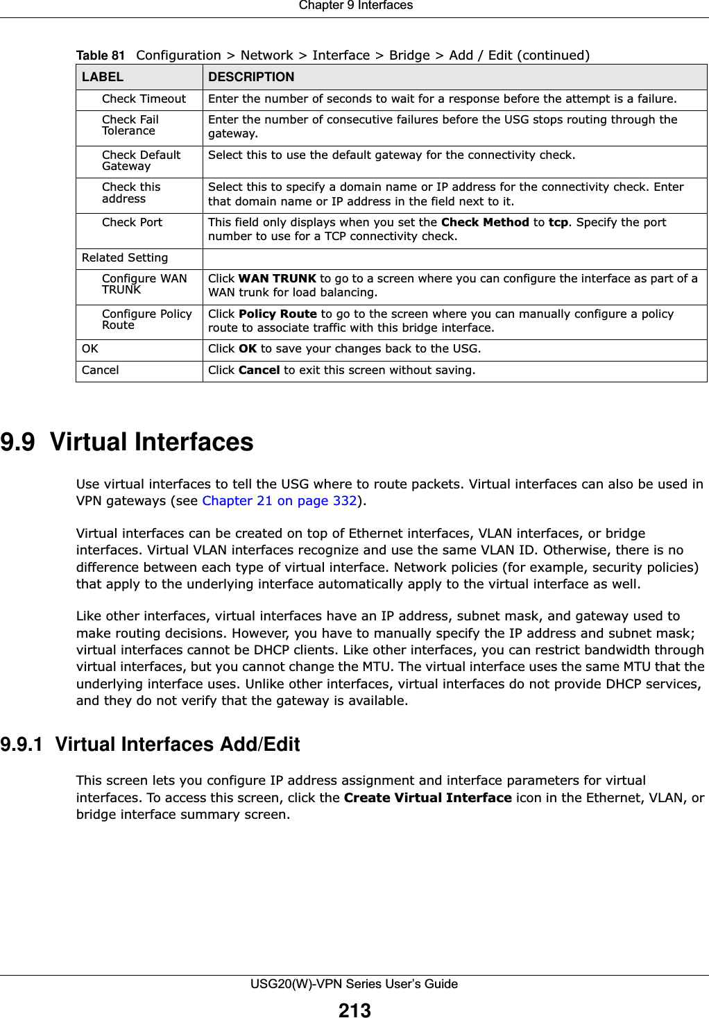
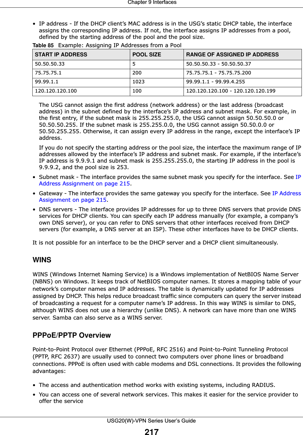
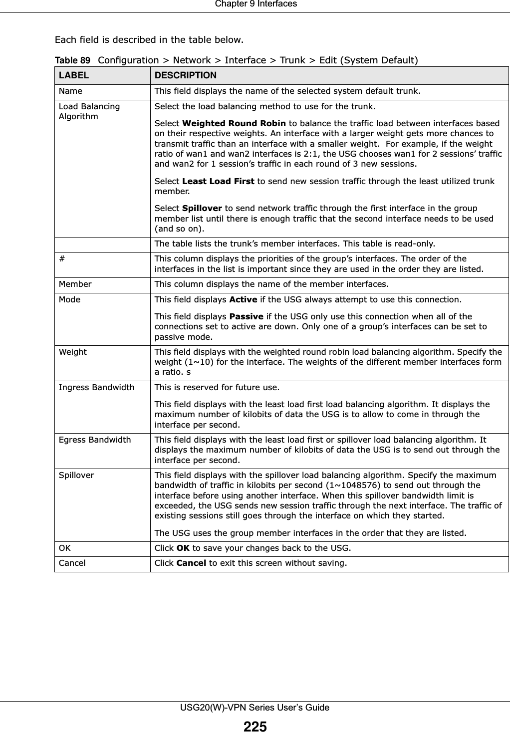
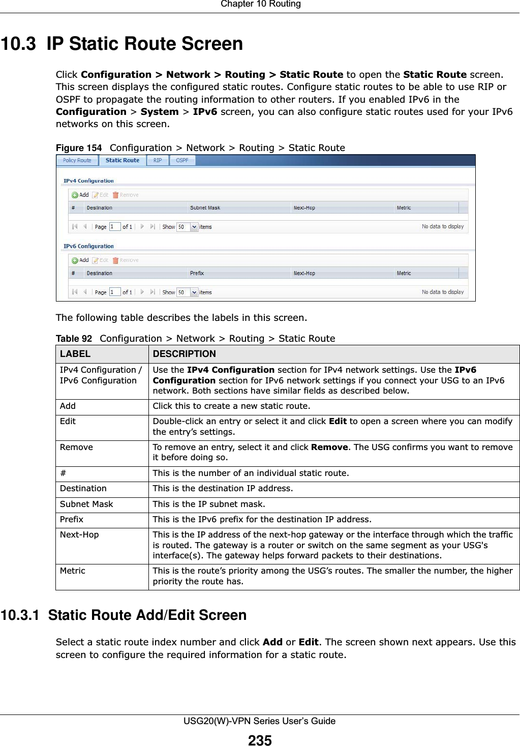
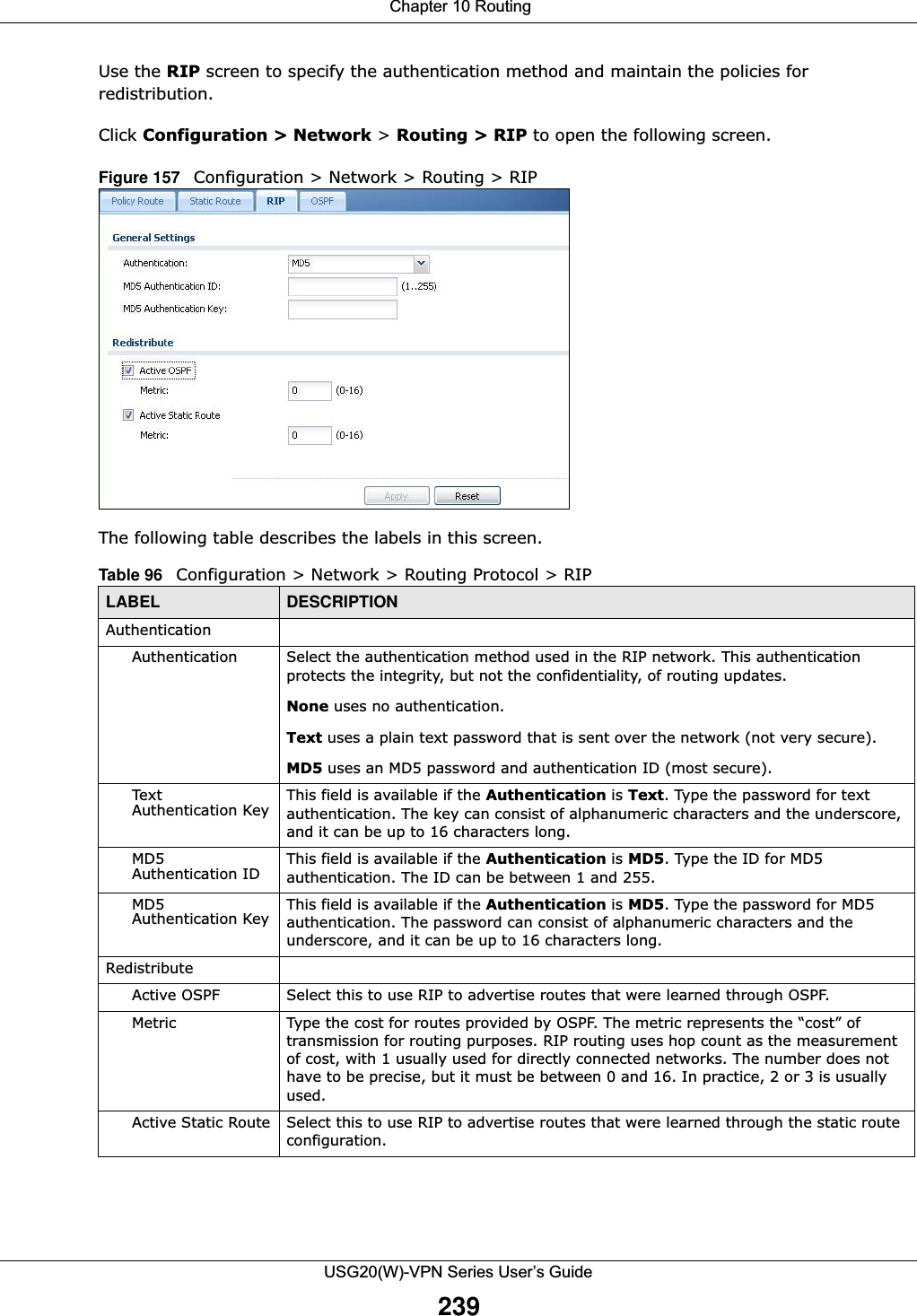
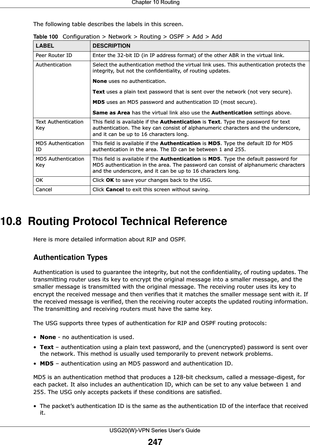
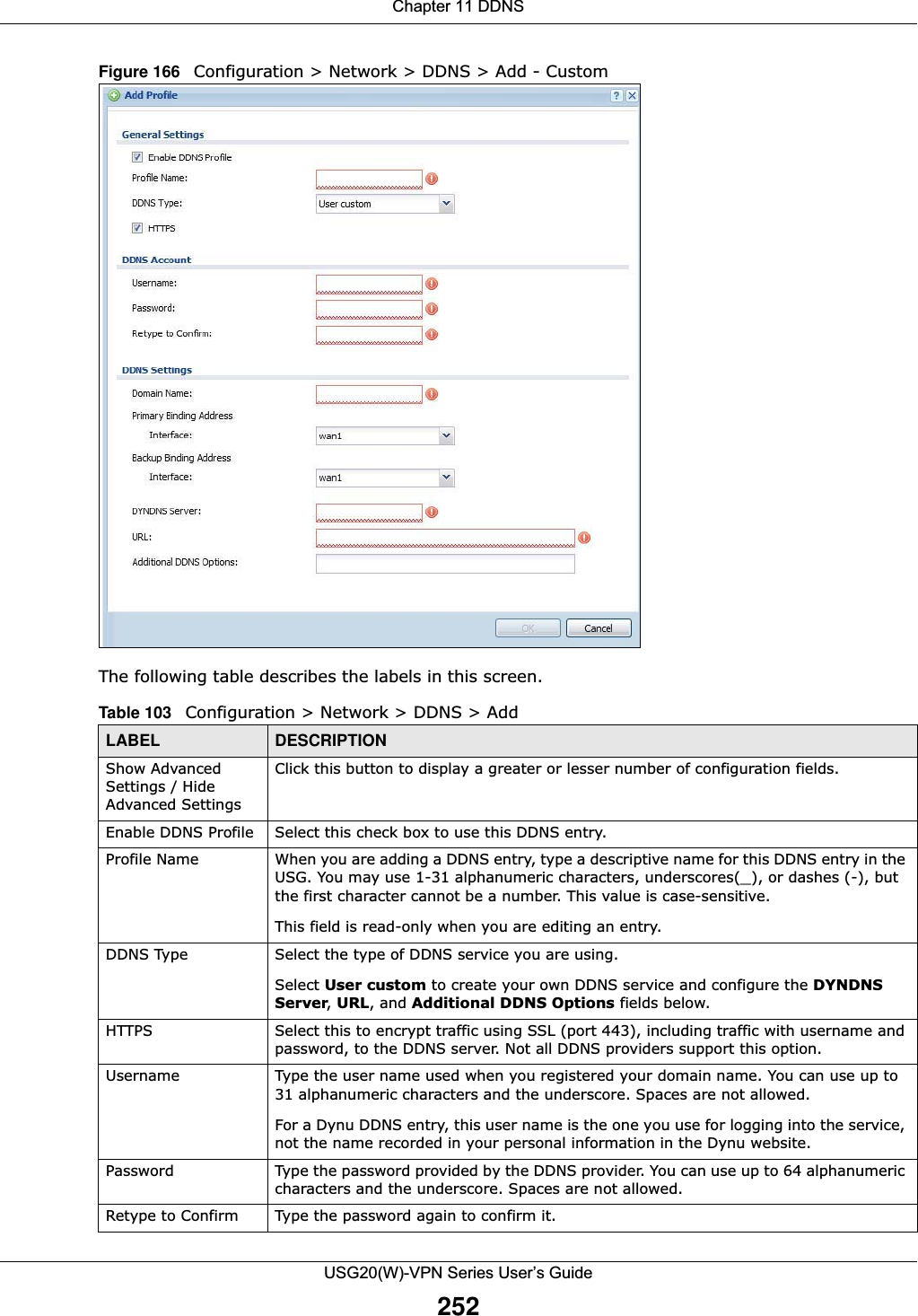
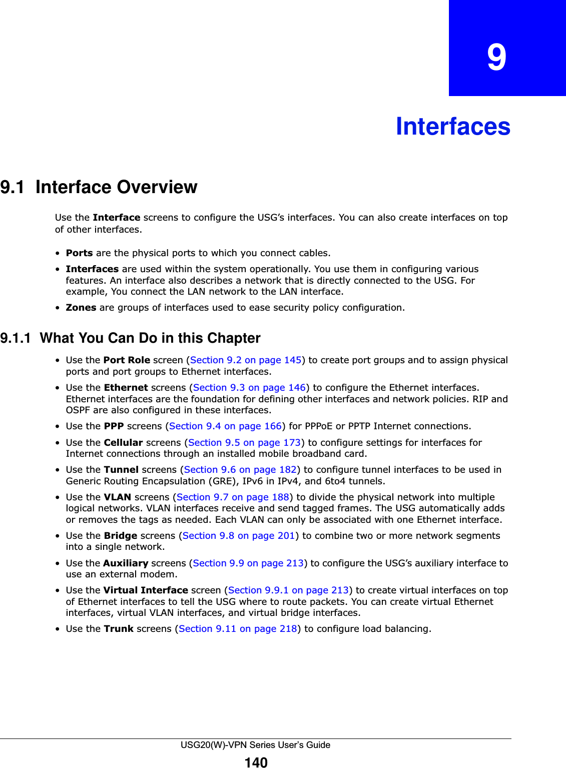
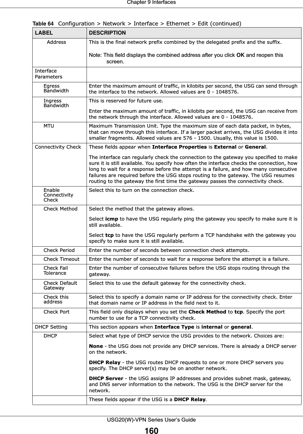
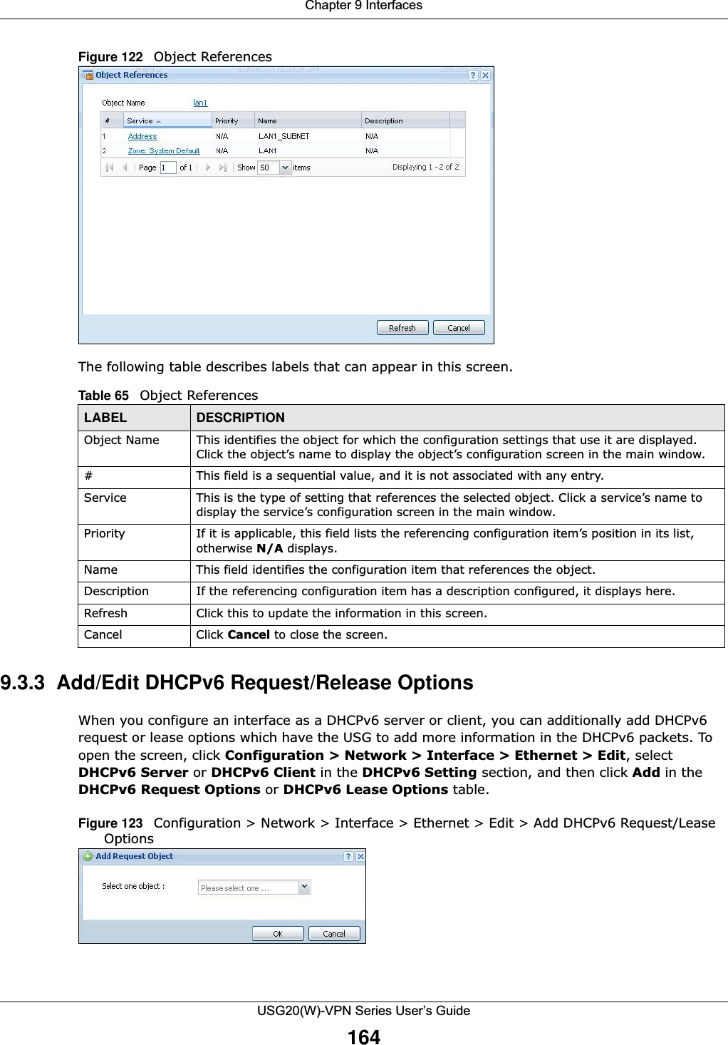
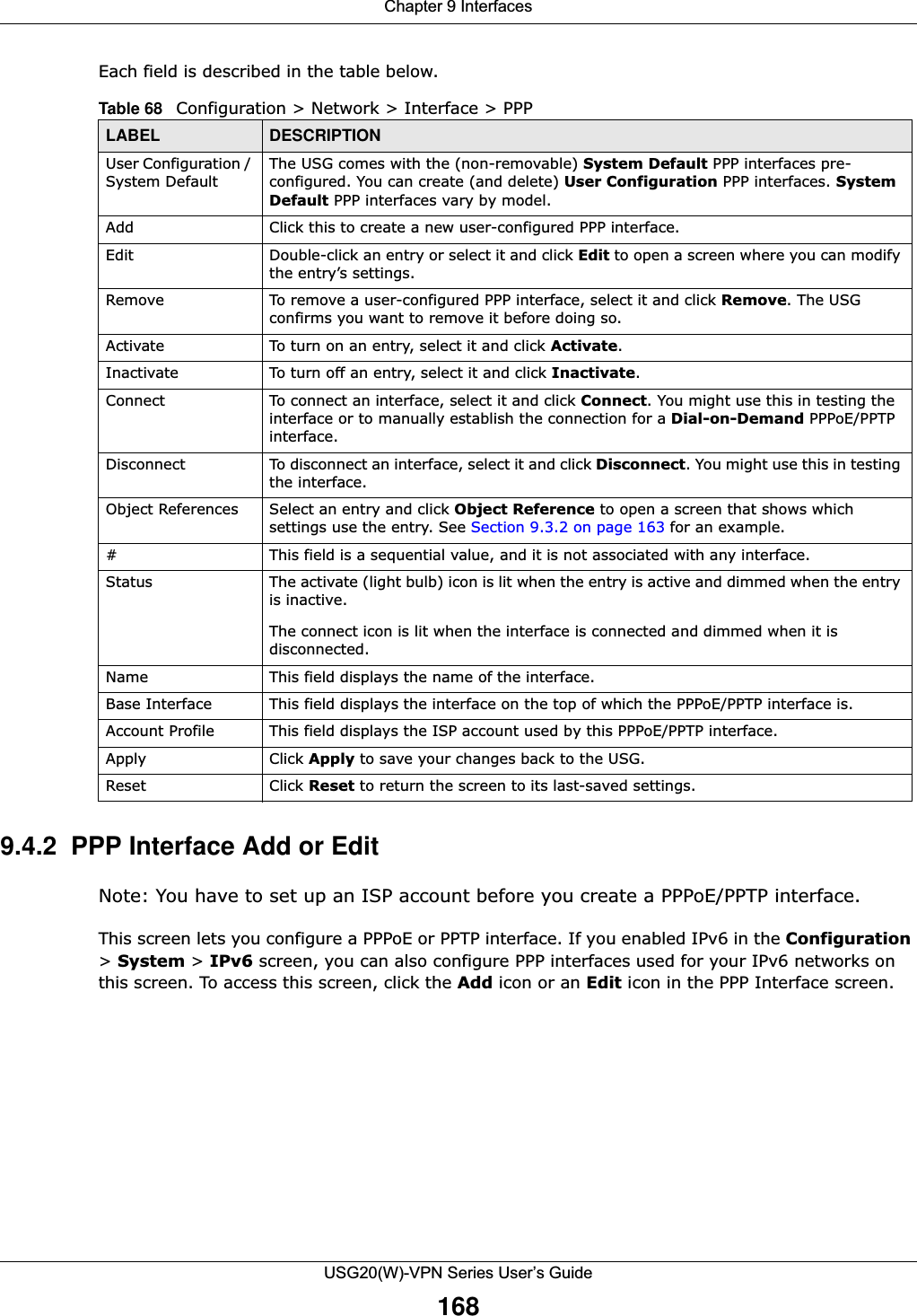
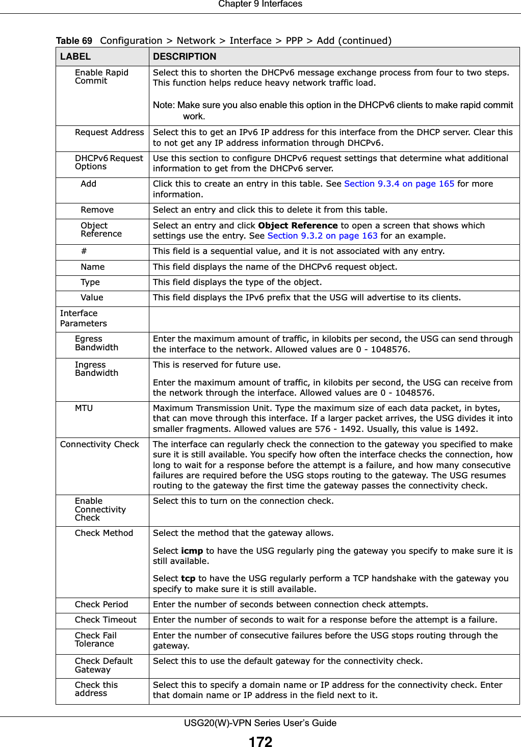
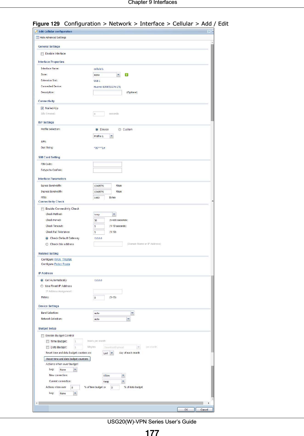
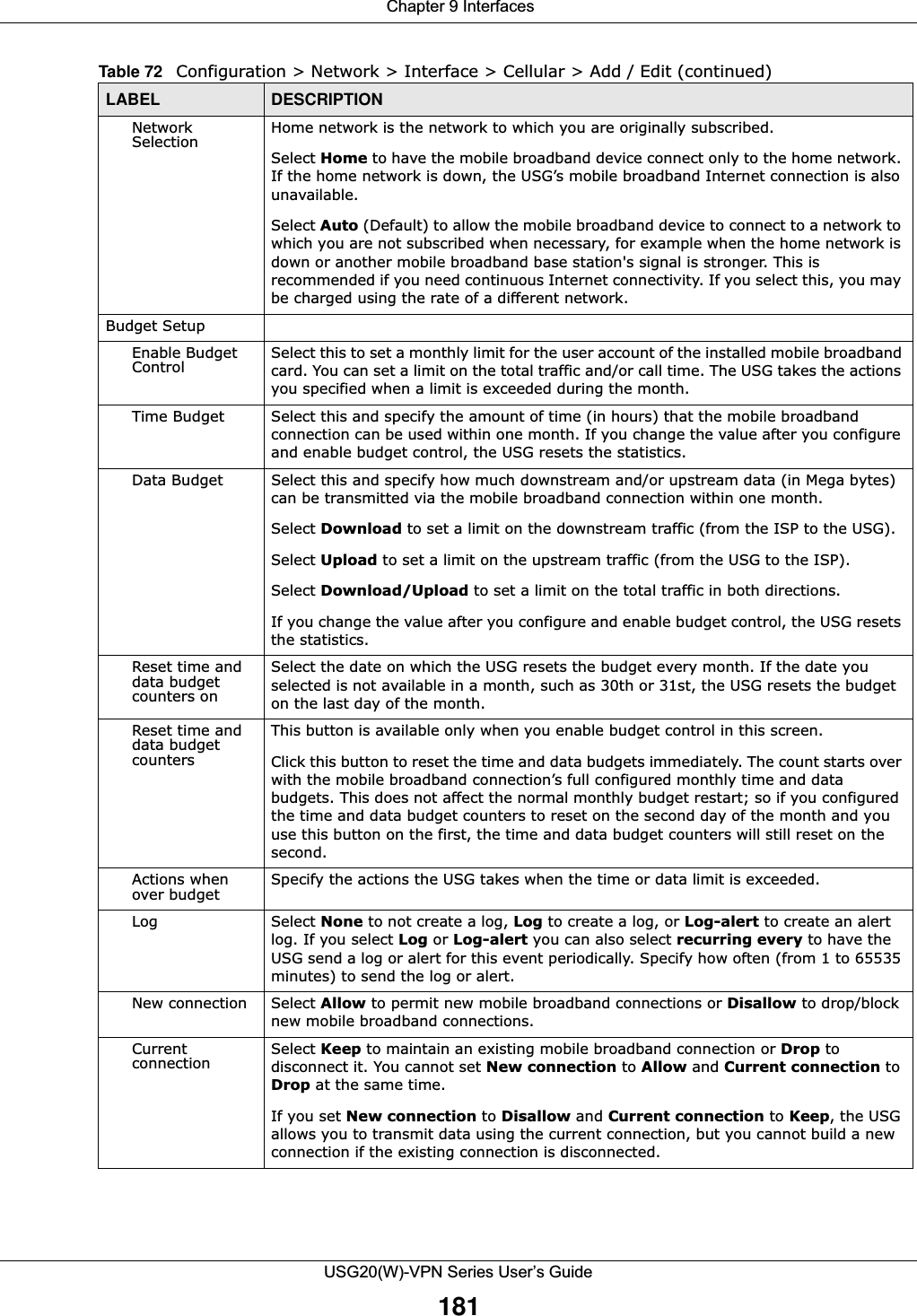
![Chapter 10 RoutingUSG20(W)-VPN Series User’s Guide229Figure 151 Configuration > Network > Routing > Policy Route The following table describes the labels in this screen. Table 90 Configuration > Network > Routing > Policy RouteLABEL DESCRIPTIONShow Advanced Settings / Hide Advanced SettingsClick this button to display a greater or lesser number of configuration fields.Enable BWM This is a global setting for enabling or disabling bandwidth management on the USG. You must enable this setting to have individual policy routes apply bandwidth management. IPv4 Configuration / IPv6 ConfigurationUse the IPv4 Configuration section for IPv4 network settings. Use the IPv6 Configuration section for IPv6 network settings if you connect your USG to an IPv6 network. Both sections have similar fields as described below.Use IPv4/IPv6 Policy Route to Override Direct RouteSelect this to have the USG forward packets that match a policy route according to the policy route instead of sending the packets directly to a connected network. Add Click this to create a new entry. Select an entry and click Add to create a new entry after the selected entry.Edit Double-click an entry or select it and click Edit to open a screen where you can modify the entry’s settings. Remove To remove an entry, select it and click Remove. The USG confirms you want to remove it before doing so.Activate To turn on an entry, select it and click Activate.Inactivate To turn off an entry, select it and click Inactivate.Move To change a rule’s position in the numbered list, select the rule and click Move to display a field to type a number for where you want to put that rule and press [ENTER] to move the rule to the number that you typed.The ordering of your rules is important as they are applied in order of their numbering.#This is the number of an individual policy route.](https://usermanual.wiki/ZyXEL-Communications/USG20W-VPN.Users-Manual-Part-2/User-Guide-2904714-Page-90.png)