ZyXEL Communications USG20W-VPN VPN Firewall User Manual Book
ZyXEL Communications Corporation VPN Firewall Book
Contents
- 1. Users Manual Part 1
- 2. Users Manual Part 2
- 3. Users Manual Part 3
- 4. Users Manual Part 4
- 5. Users Manual Part 5
Users Manual Part 3
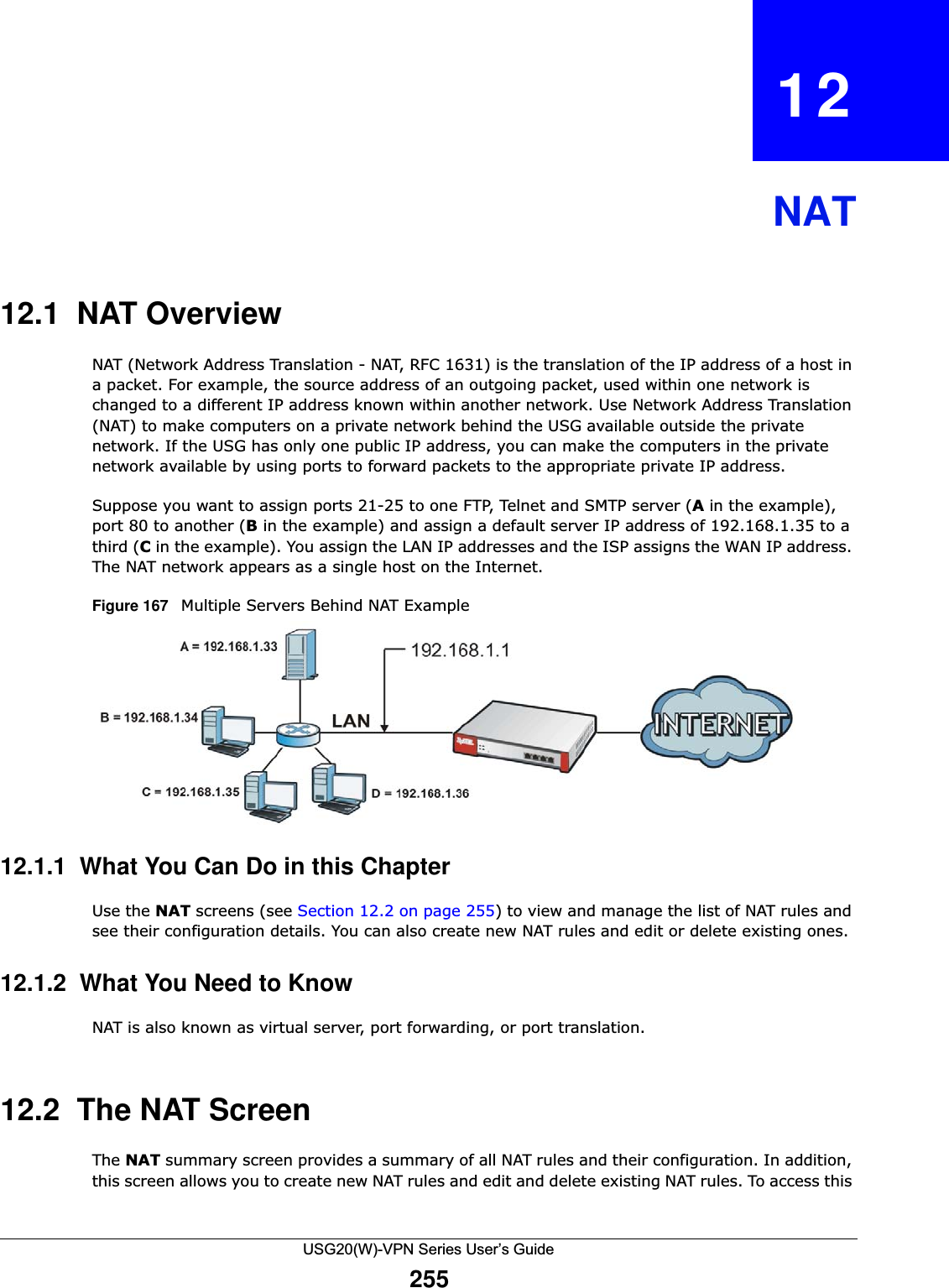
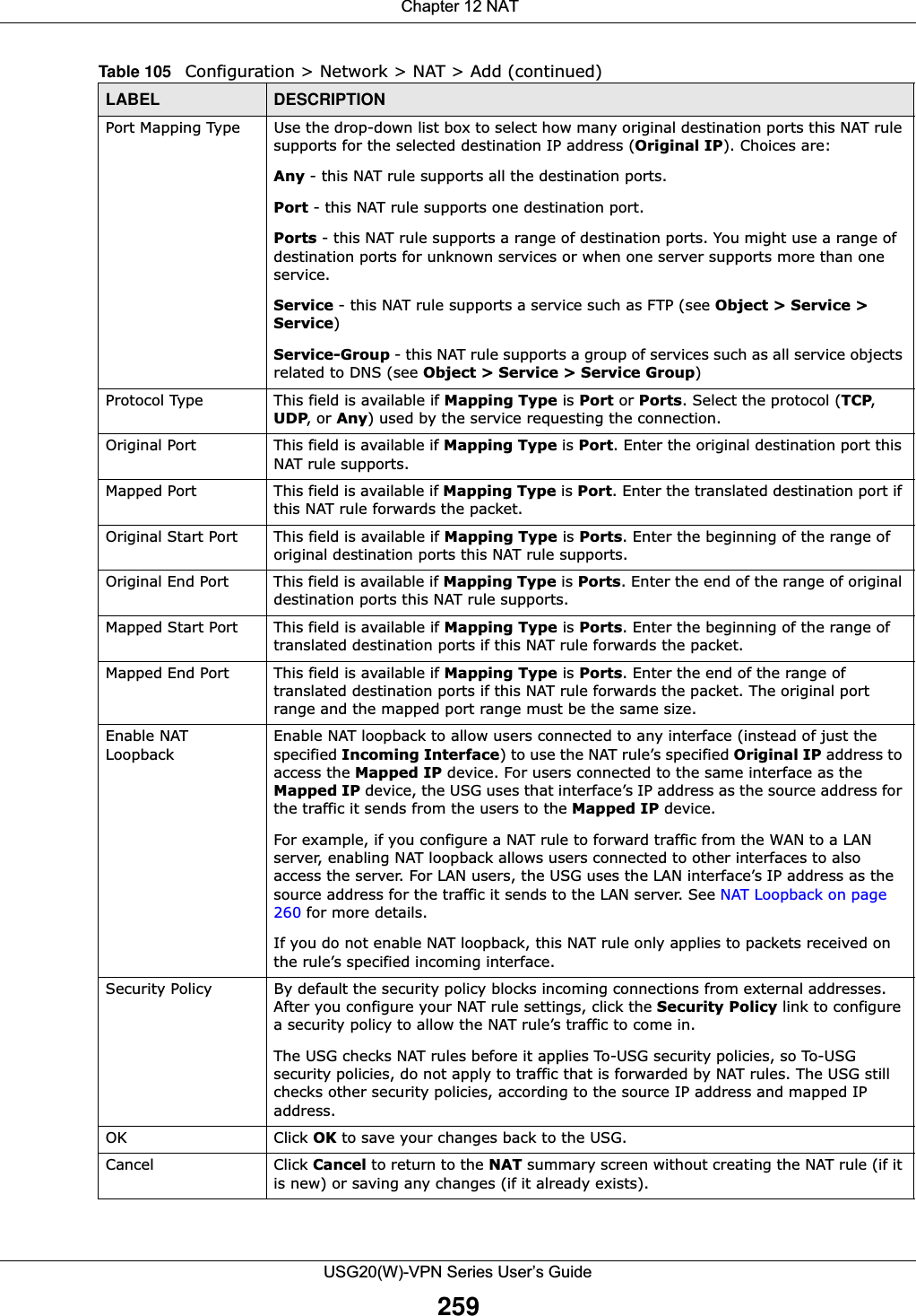
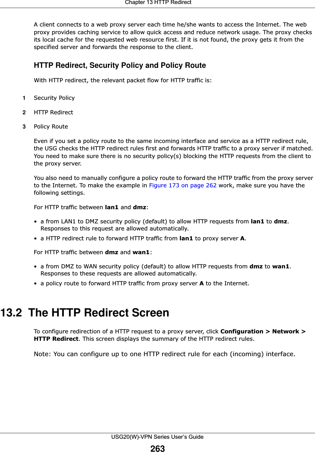
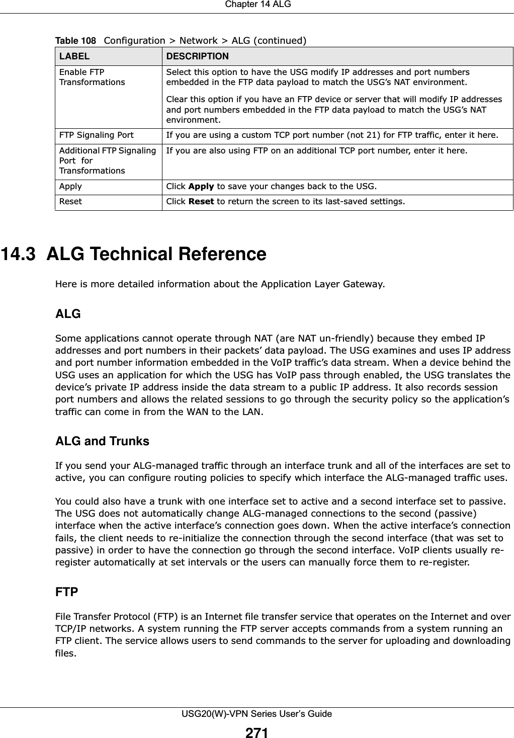
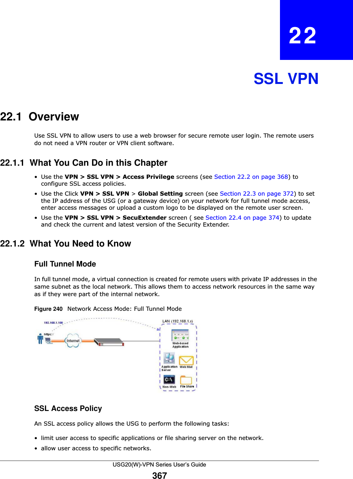
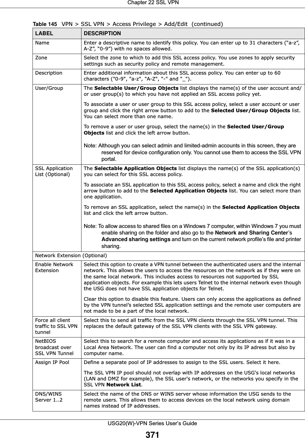
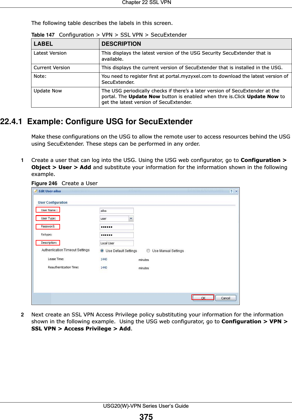
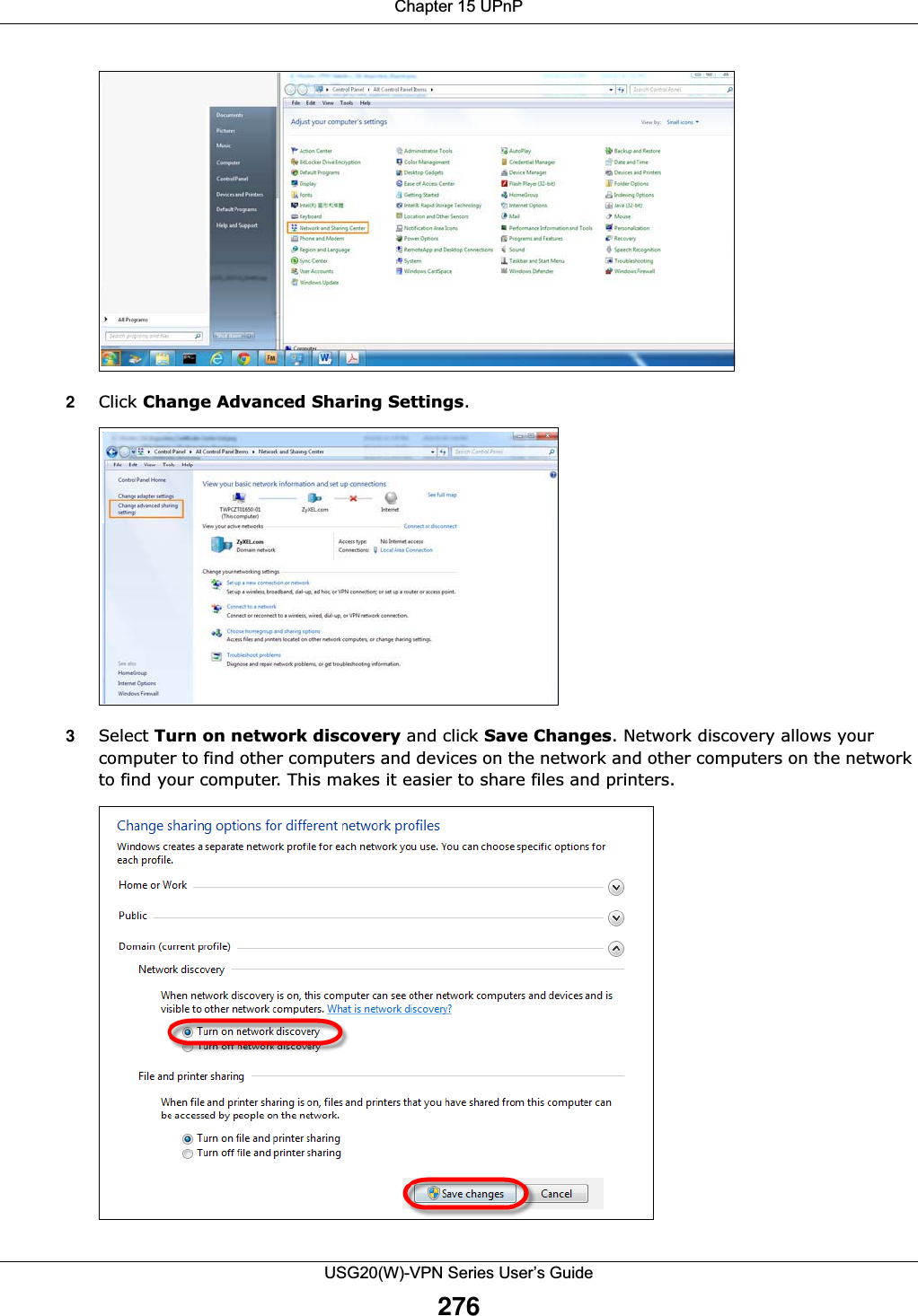
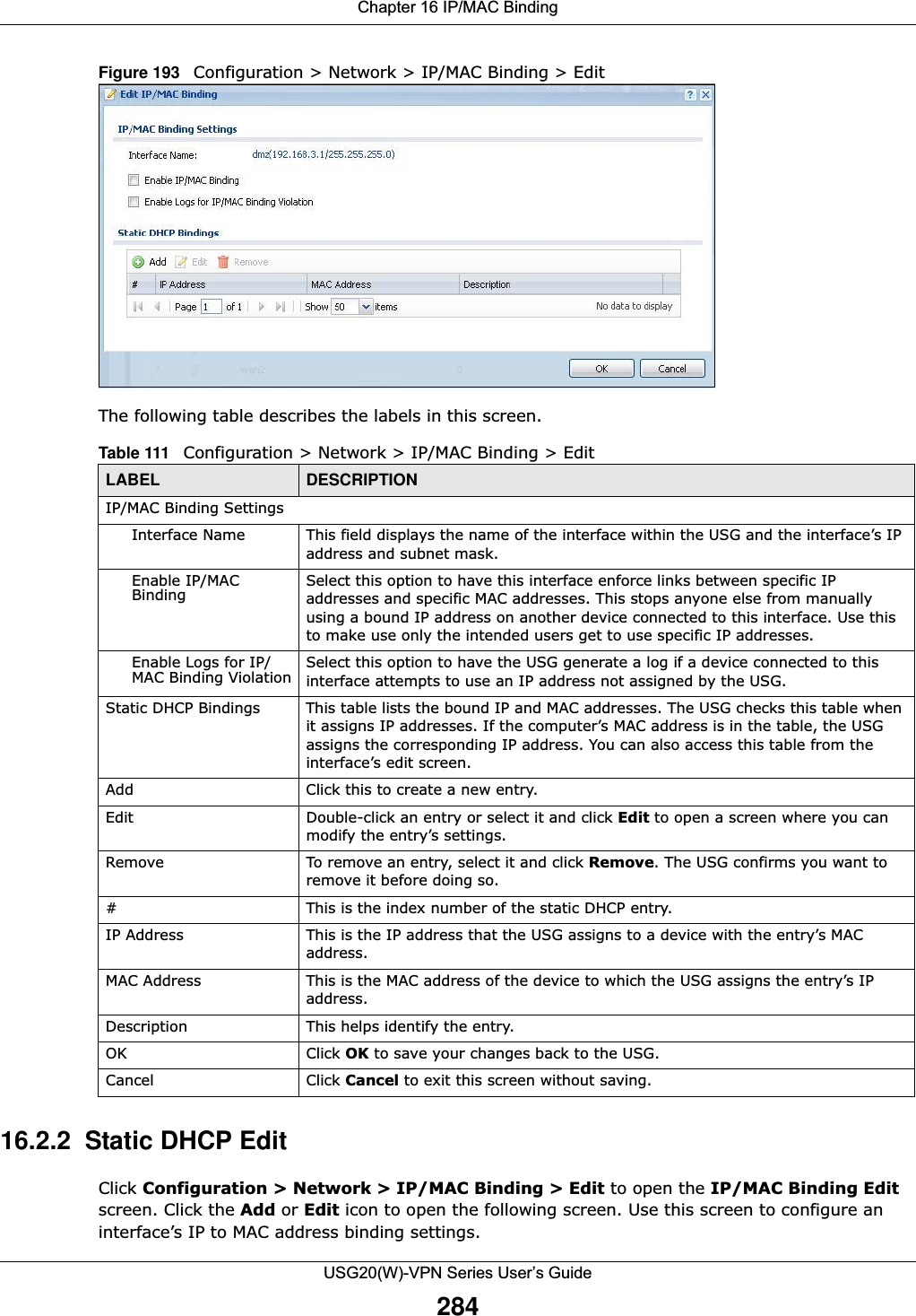
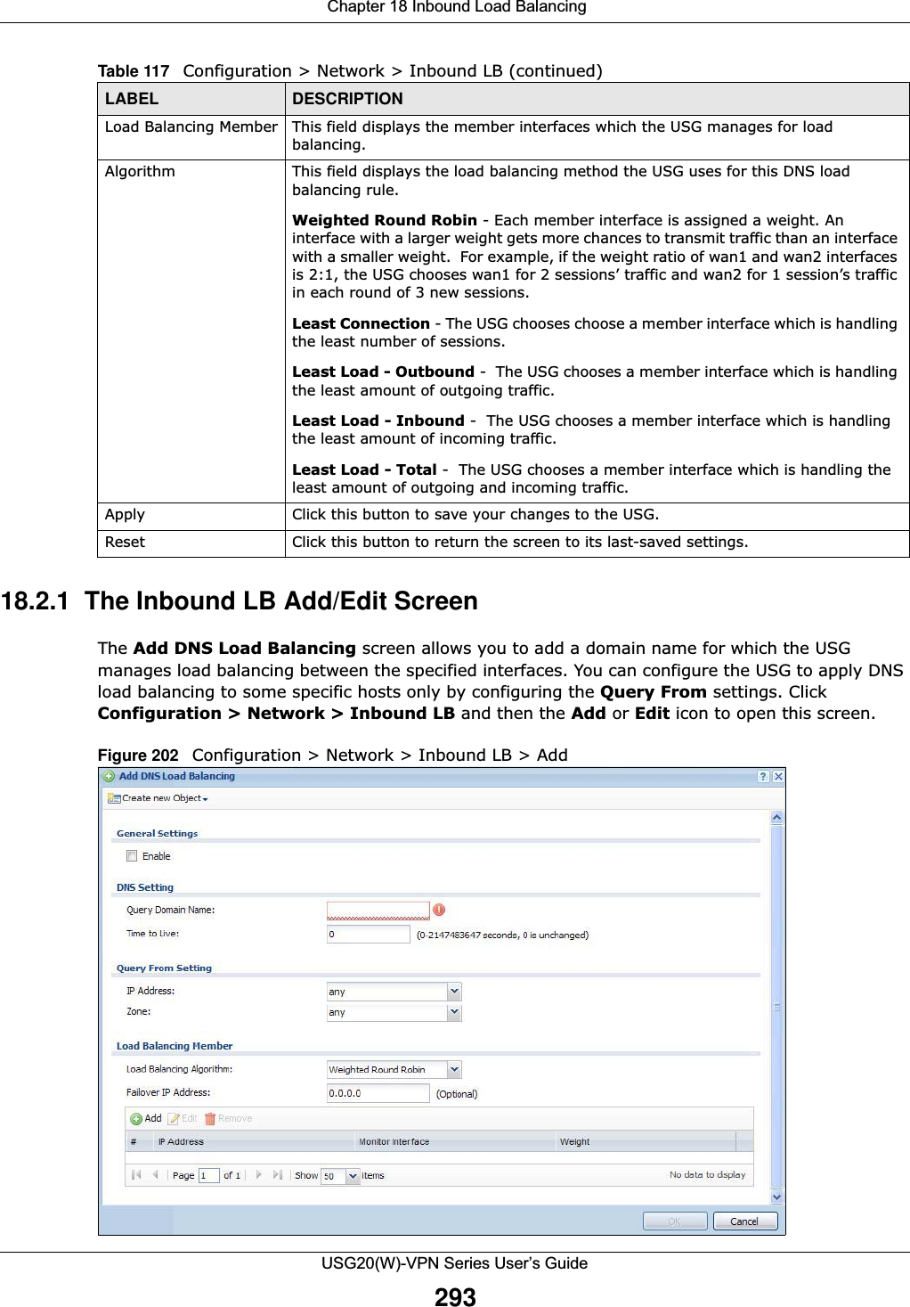
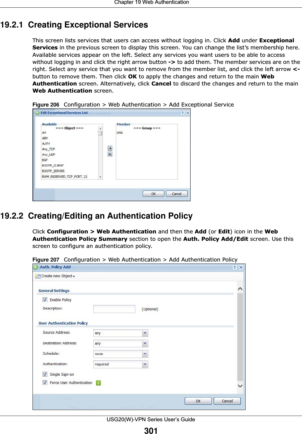
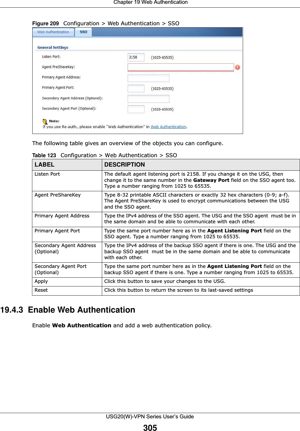
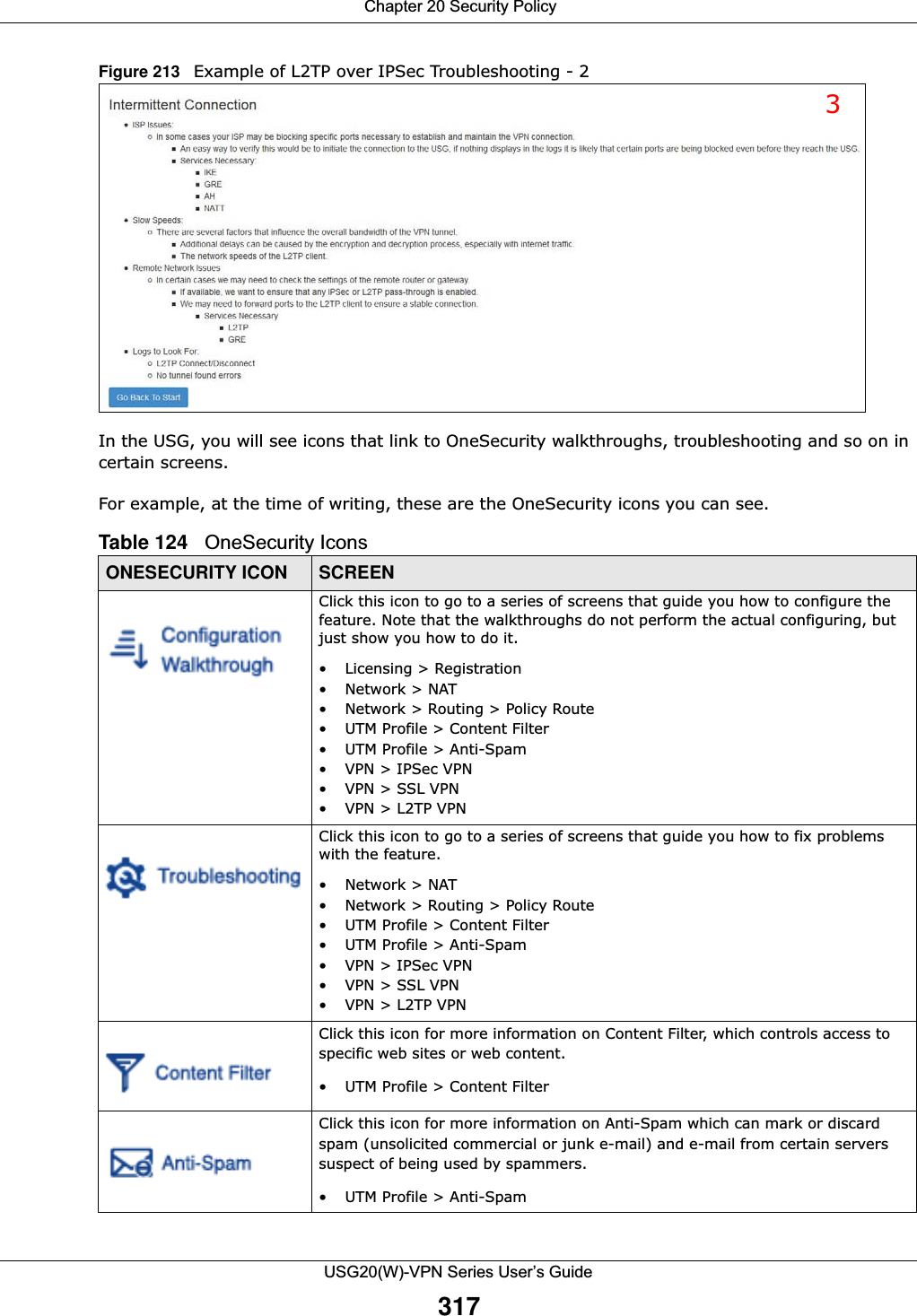
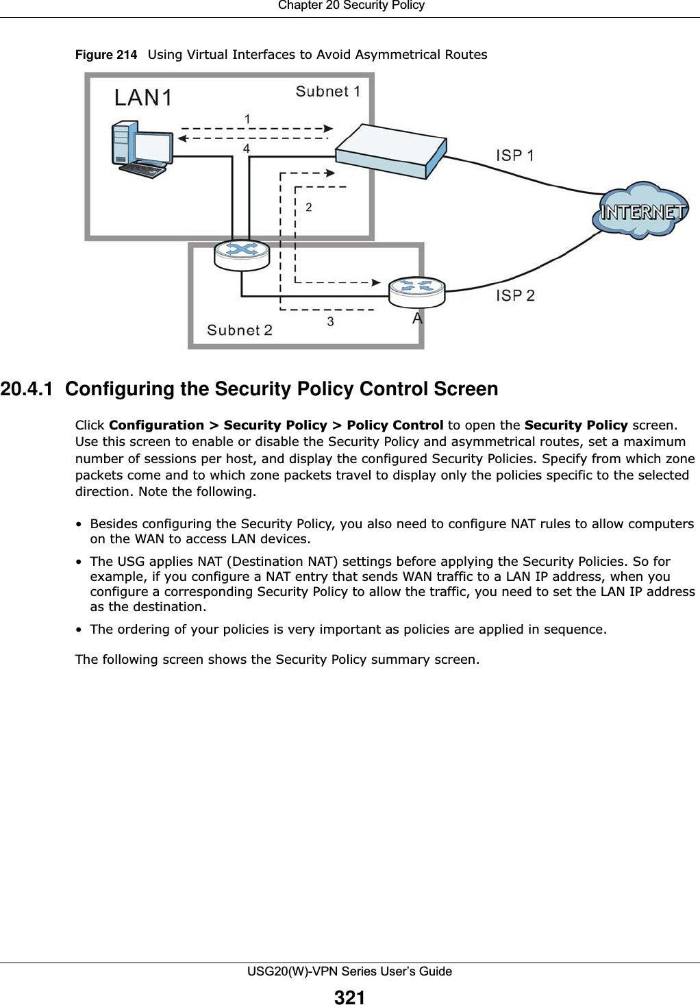
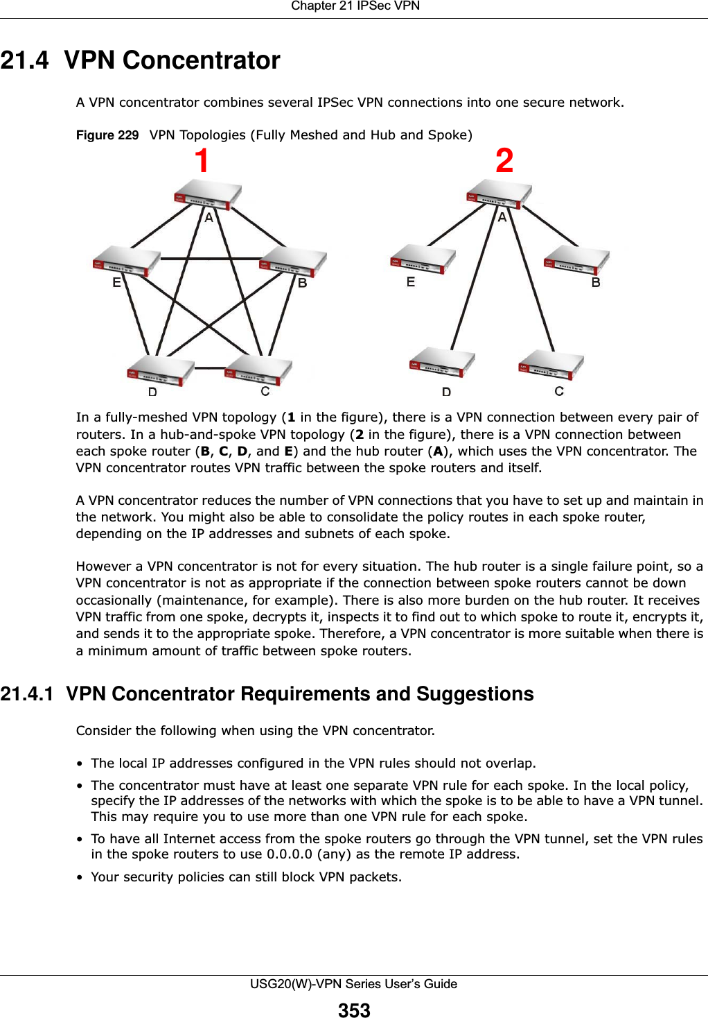
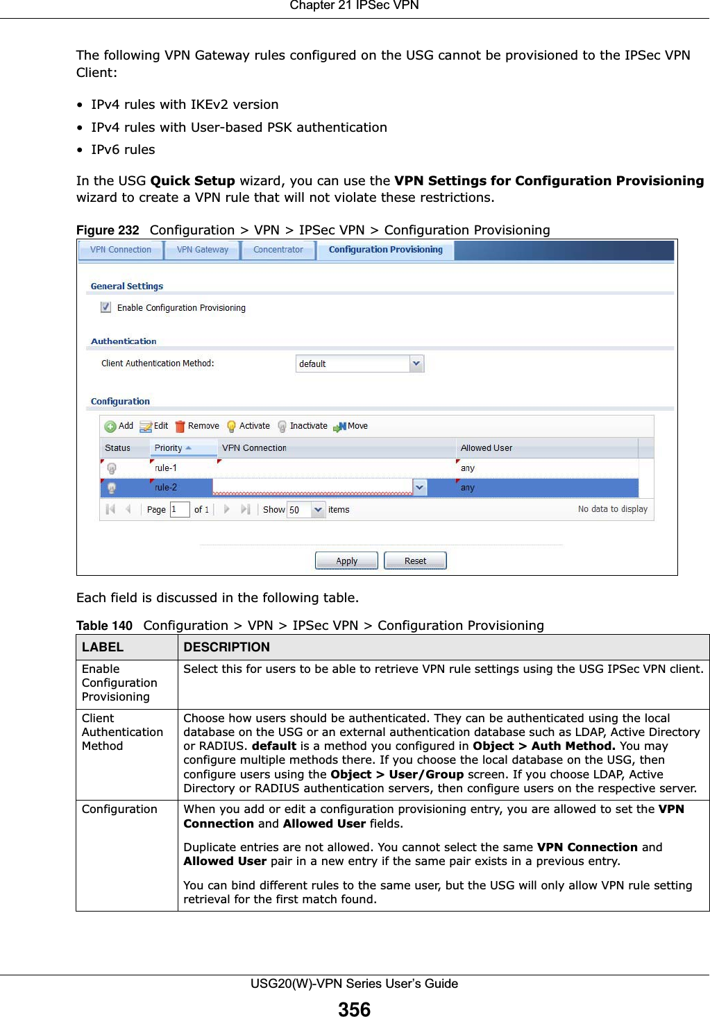
![Chapter 15 UPnPUSG20(W)-VPN Series User’s Guide275The following table describes the fields in this screen. 15.4 Technical ReferenceThe sections show examples of using UPnP. 15.4.1 Turning on UPnP in Windows 7 ExampleThis section shows you how to use the UPnP feature in Windows 7. UPnP server is installed in Windows 7. Activate UPnP on the USG.Make sure the computer is connected to a LAN port of the USG. Turn on your computer and the USG. 1Click the start icon, Control Panel and then the Network and Sharing Center.Table 109 Configuration > Network > UPnPLABEL DESCRIPTIONEnable UPnP Select this check box to activate UPnP on the USG. Be aware that anyone could use a UPnP application to open the web configurator's login screen without entering the USG's IP address (although you must still enter the password to access the web configurator).Enable NAT-PMP NAT Port Mapping Protocol (NAT-PMP) automates port forwarding to allow a computer in a private network (behind the USG) to automatically configure the USG to allow computers outside the private network to contact it.Select this check box to activate NAT-PMP on the USG. Be aware that anyone could use a NAT-PMP application to open the web configurator's login screen without entering the USG's IP address (although you must still enter the password to access the web configurator).Allow UPnP or NAT-PMP to pass through FirewallSelect this check box to allow traffic from UPnP-enabled or NAT-PMP-enabled applications to bypass the security policy. Clear this check box to have the security policy block all UPnP or NAT-PMP application packets (for example, MSN packets).Outgoing WAN Interface Select through which WAN interface(s) you want to send out traffic from UPnP-enabled or NAT-PMP-enabled applications. If the WAN interface you select loses its connection, the USG attempts to use the other WAN interface. If the other WAN interface also does not work, the USG drops outgoing packets from UPnP-enabled or NAT-PMP-enabled applications.Support LAN List The Available list displays the name(s) of the internal interface(s) on which the USG supports UPnP and/or NAT-PMP. To enable UPnP and/or NAT-PMP on an interface, you can double-click a single entry to move it or use the [Shift] or [Ctrl] key to select multiple entriess and click the right arrow button to add to the Member list. To remove an interface, select the name(s) in the Member list and click the left arrow button.Apply Click Apply to save your changes back to the USG.Reset Click Reset to return the screen to its last-saved settings.](https://usermanual.wiki/ZyXEL-Communications/USG20W-VPN.Users-Manual-Part-3/User-Guide-2904715-Page-21.png)
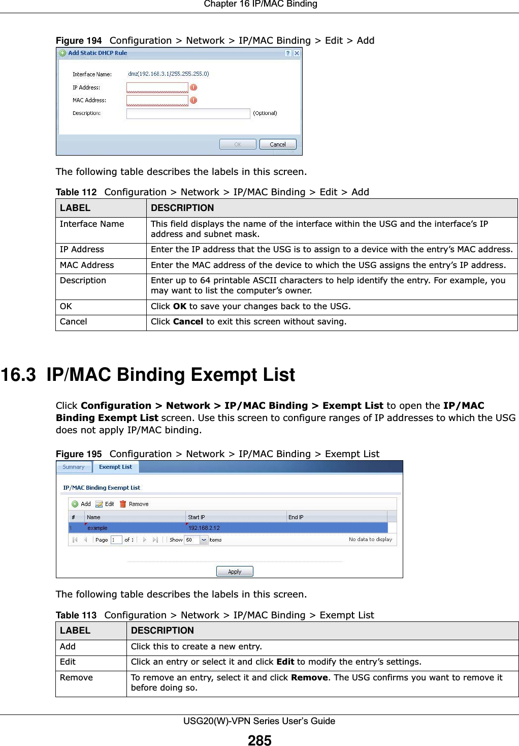
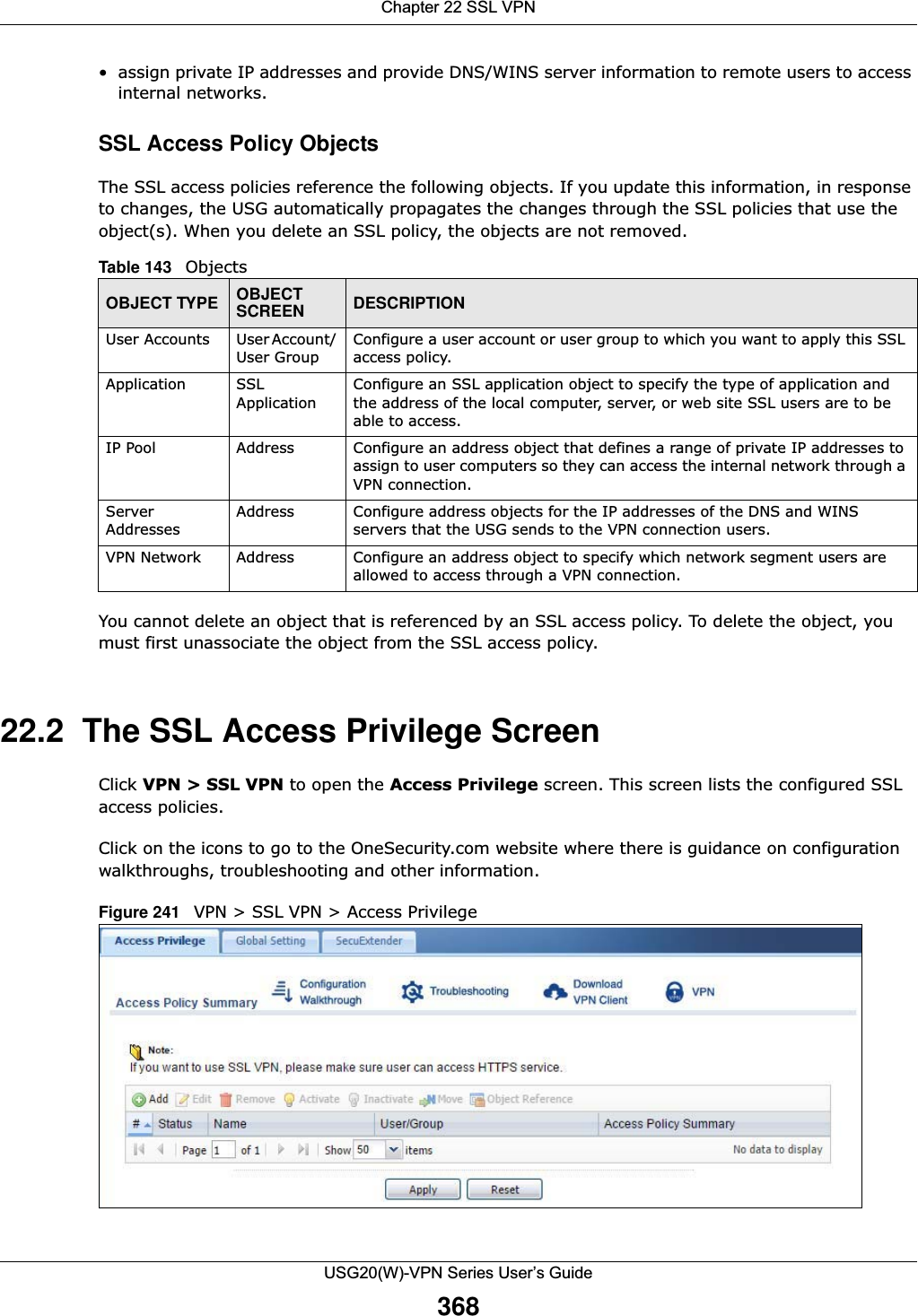
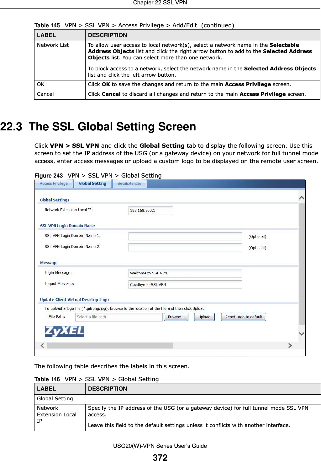
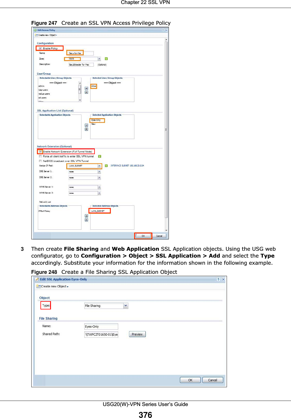
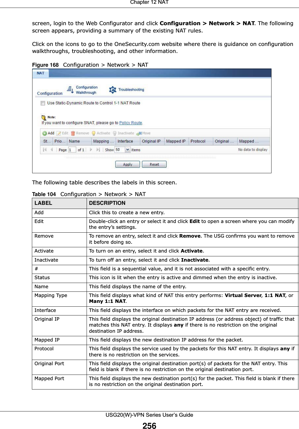
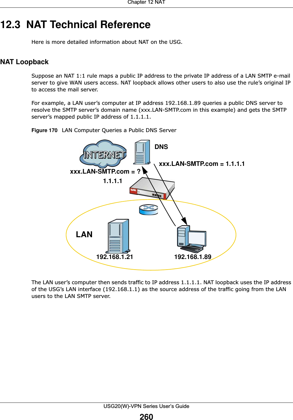
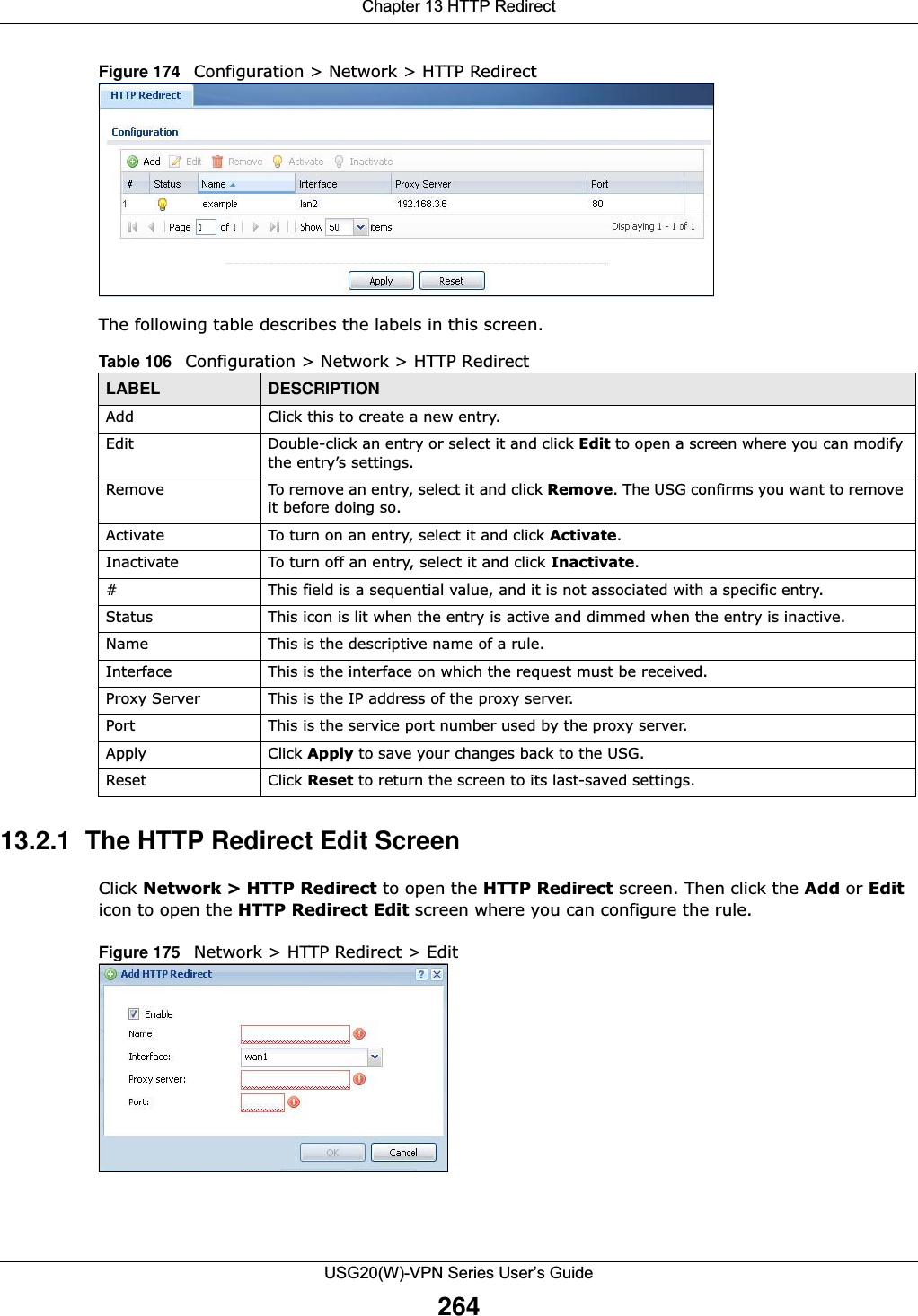
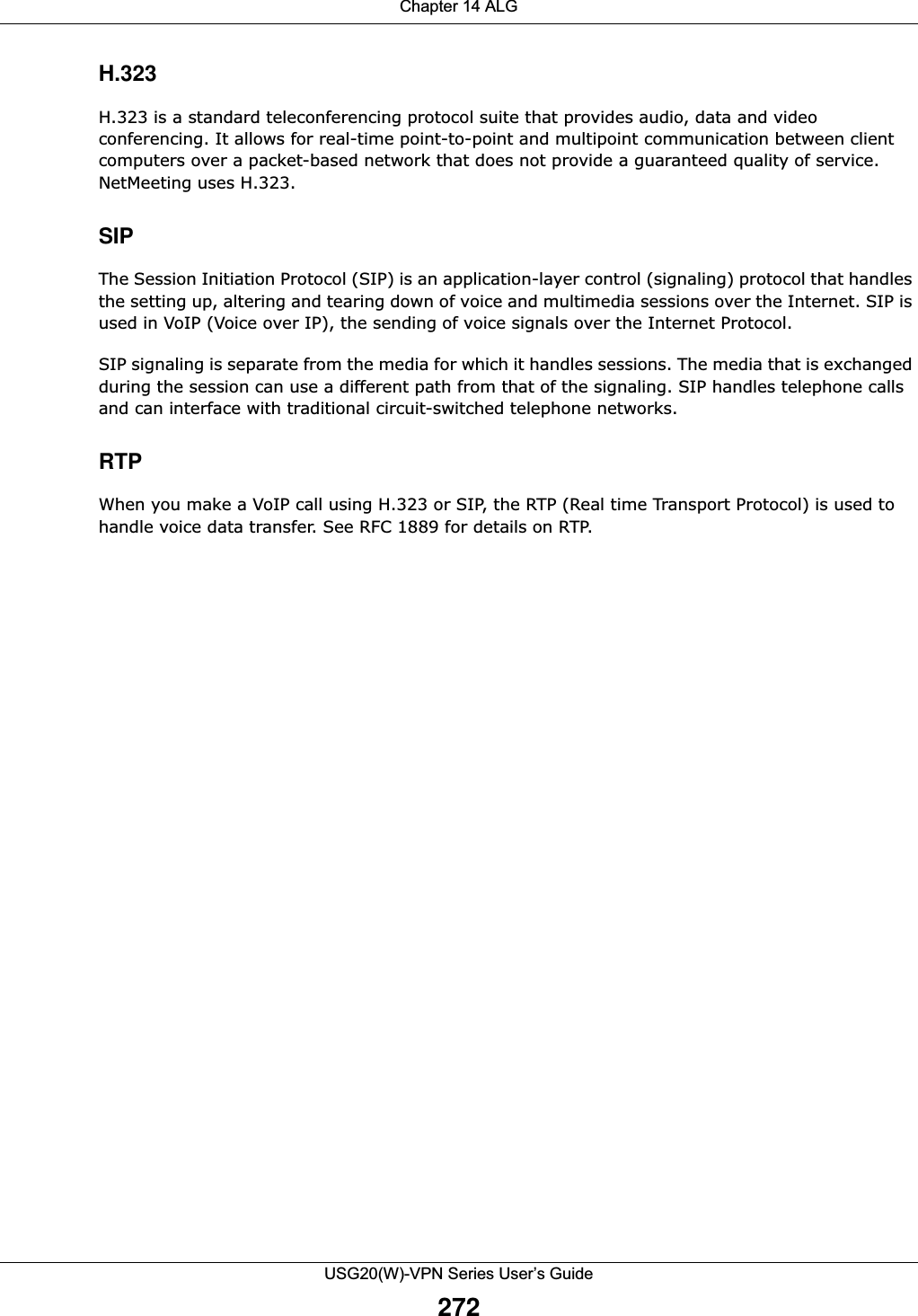
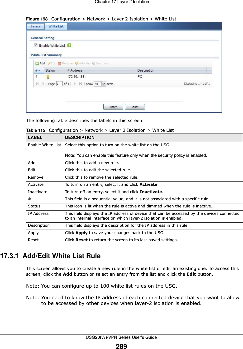
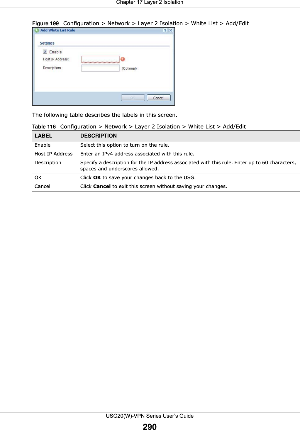
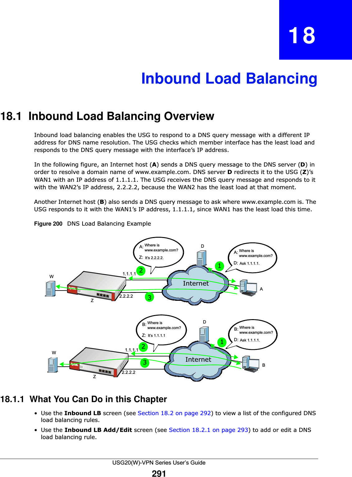
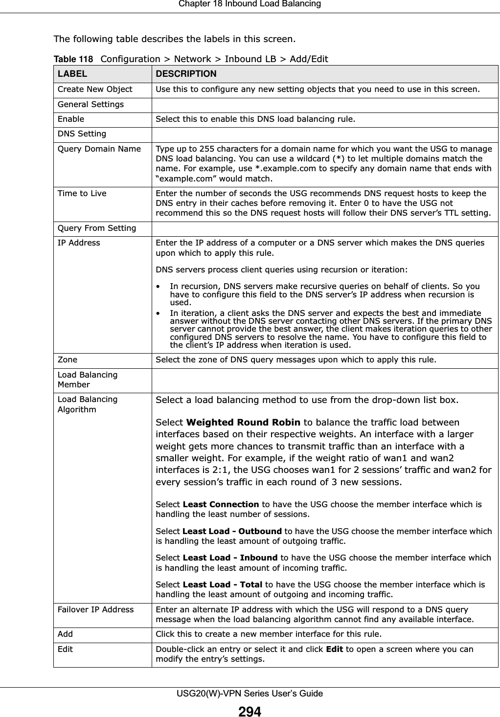
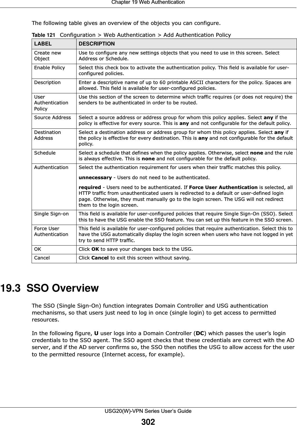
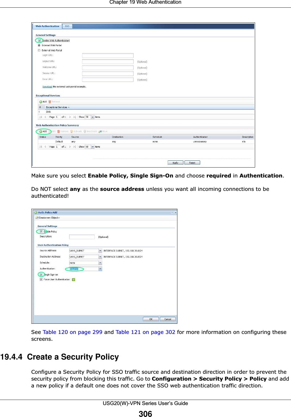
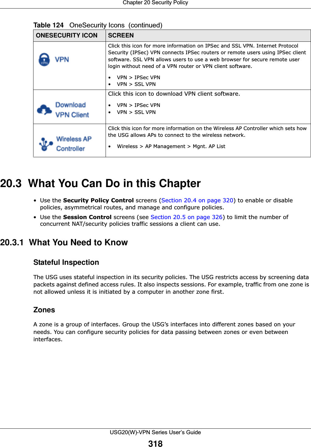
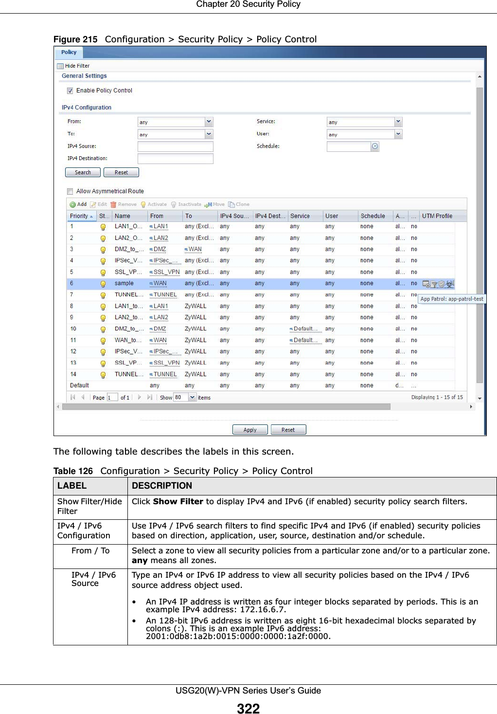
![Chapter 17 Layer 2 IsolationUSG20(W)-VPN Series User’s Guide28817.2 Layer-2 Isolation General Screen This screen allows you to enable Layer-2 isolation on the USG and specific internal interface(s). To access this screen click Configuration > Network > Layer 2 Isolation.Figure 197 Configuration > Network > Layer 2 Isolation The following table describes the labels in this screen. 17.3 White List ScreenIP addresses that are not listed in the white list are blocked from communicating with other devices in the layer-2-isolation-enabled internal interface(s) except for broadcast packets. To access this screen click Configuration > Network > Layer 2 Isolation > White List.Table 114 Configuration > Network > Layer 2 IsolationLABEL DESCRIPTIONEnable Layer2 IsolationSelect this option to turn on the layer-2 isolation feature on the USG. Note: You can enable this feature only when the security policy is enabled.Member List The Available list displays the name(s) of the internal interface(s) on which you can enable layer-2 isolation. To enable layer-2 isolation on an interface, you can double-click a single entry to move it or use the [Shift] or [Ctrl] key to select multiple entriess and click the right arrow button to add to the Member list. To remove an interface, select the name(s) in the Member list and click the left arrow button.Apply Click Apply to save your changes back to the USG.Reset Click Reset to return the screen to its last-saved settings.](https://usermanual.wiki/ZyXEL-Communications/USG20W-VPN.Users-Manual-Part-3/User-Guide-2904715-Page-34.png)
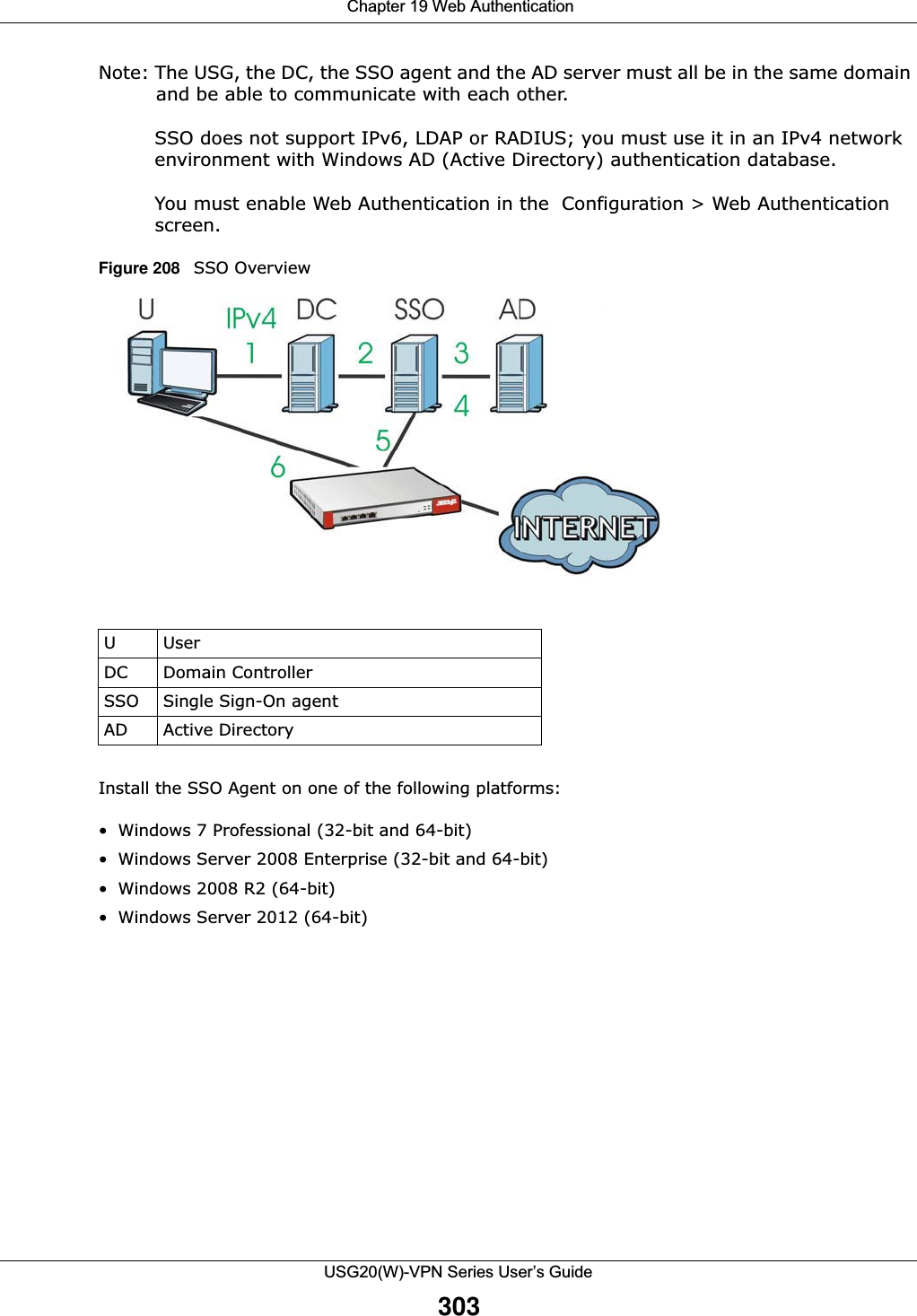
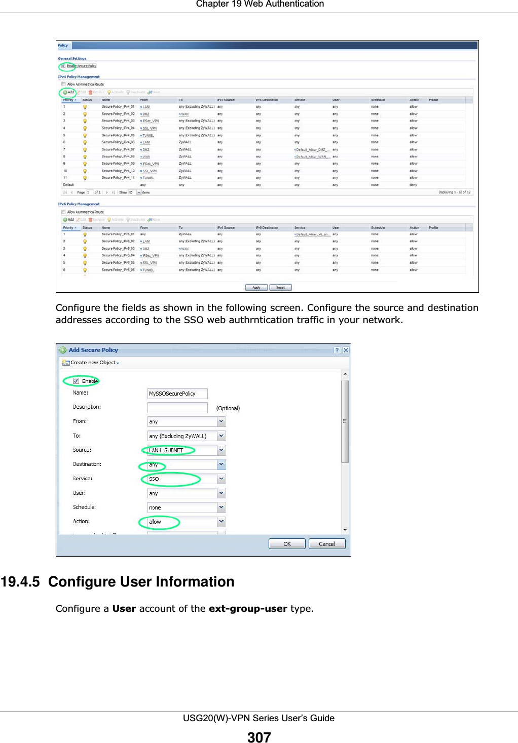
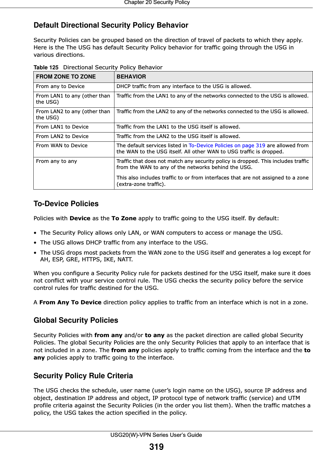
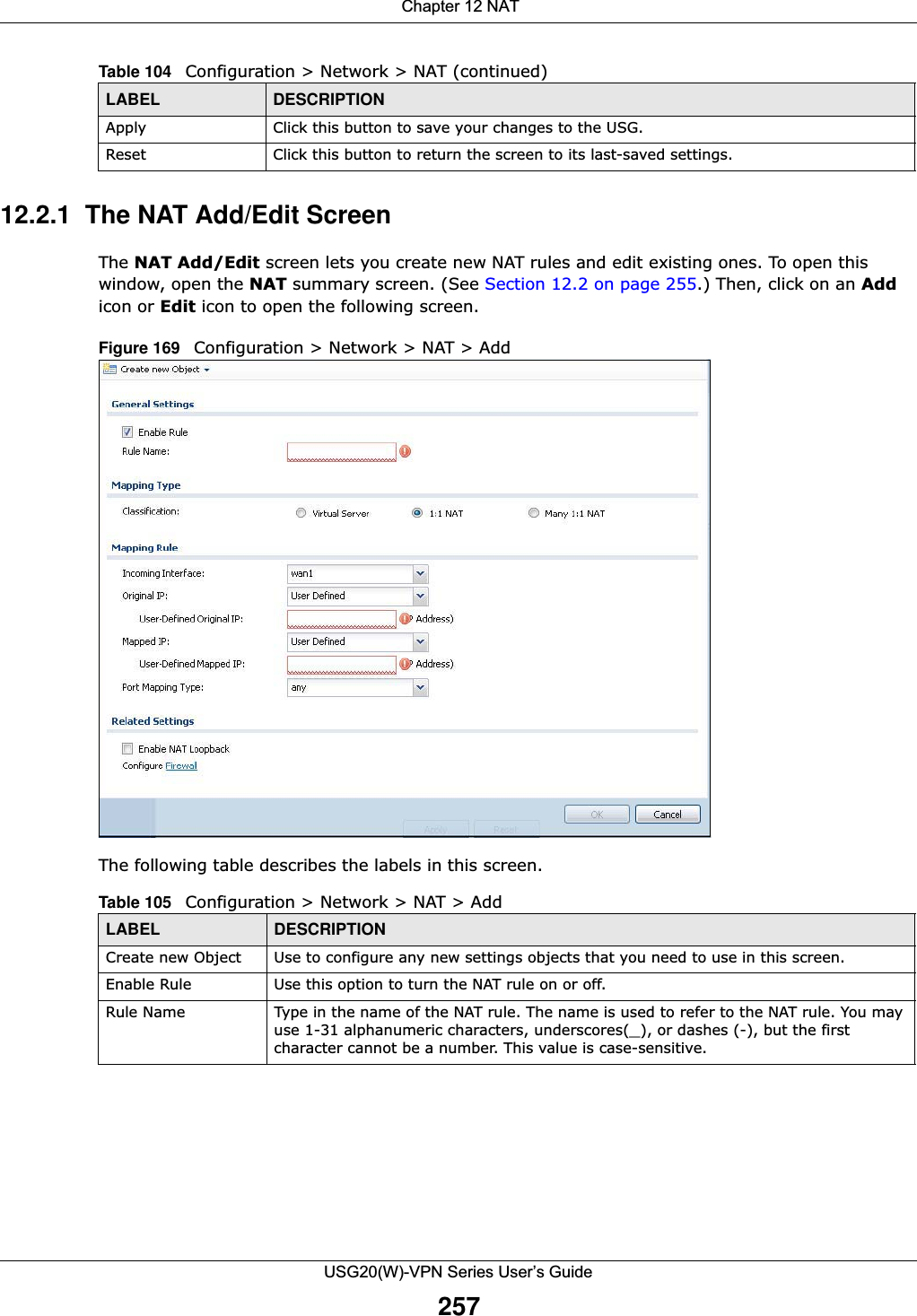
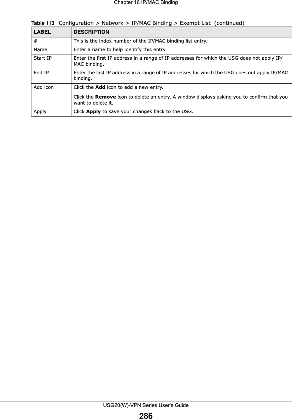
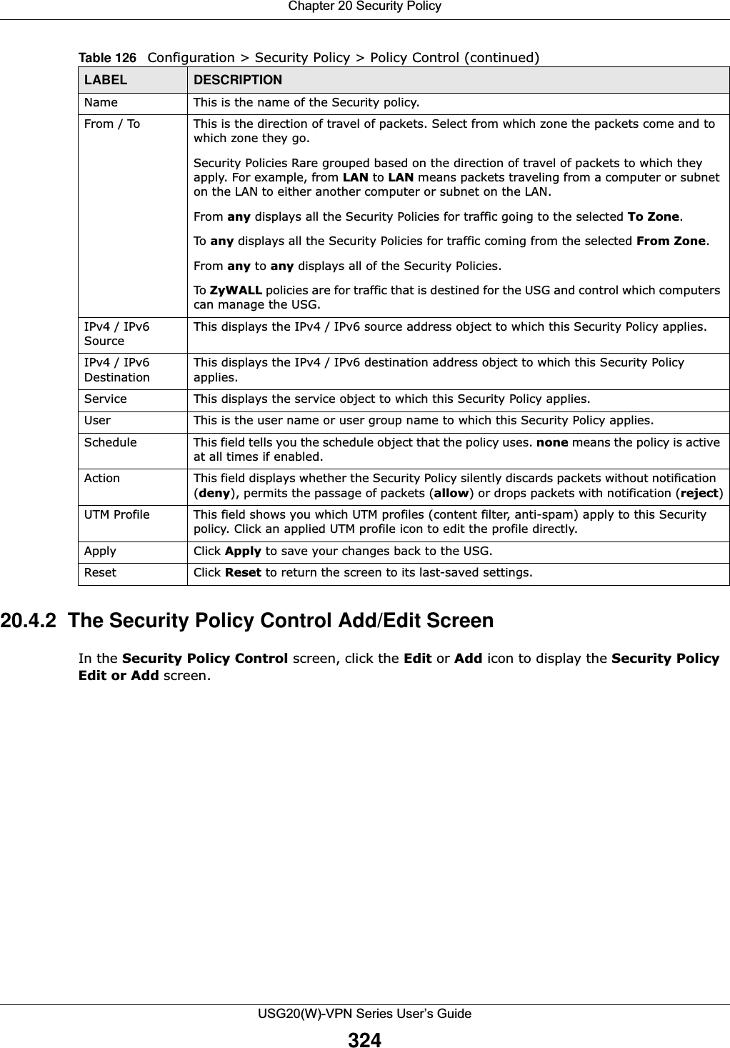
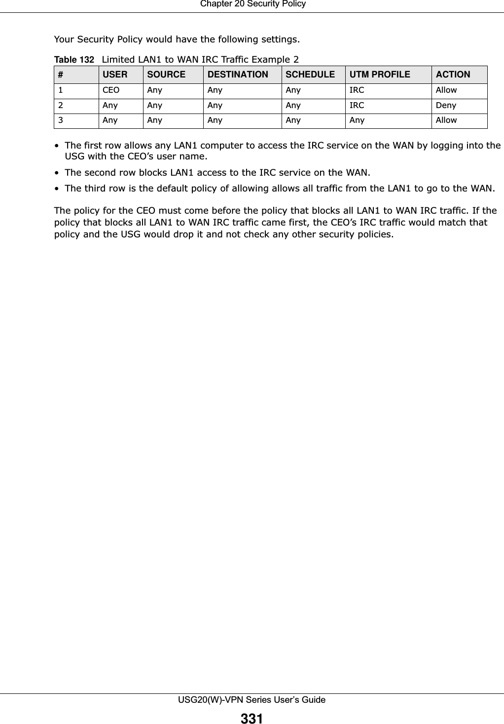
![Chapter 20 Security PolicyUSG20(W)-VPN Series User’s Guide323IPv4 / IPv6 Destination Type an IPv4 or IPv6 IP address to view all security policies based on the IPv4 / IPv6 destination address object used. • An IPv4 IP address is written as four integer blocks separated by periods. This is an example IPv4 address: 172.16.6.7.• An 128-bit IPv6 address is written as eight 16-bit hexadecimal blocks separated by colons (:). This is an example IPv6 address: 2001:0db8:1a2b:0015:0000:0000:1a2f:0000.Service View all security policies based the service object used.User View all security policies based on user or user group object used.Schedule View all security policies based on the schedule object used.General Settings Enable or disable the Security Policy feature on the USG.Enable Policy ControlSelect this to activate Security Policy on the USG to perform access control.IPv4/IPv6 Policy ManagementUse the following items to manage IPv4 and IPv6 policies.Allow Asymmetrical RouteIf an alternate gateway on the LAN has an IP address in the same subnet as the USG’s LAN IP address, return traffic may not go through the USG. This is called an asymmetrical or “triangle” route. This causes the USG to reset the connection, as the connection has not been acknowledged.Select this check box to have the USG permit the use of asymmetrical route topology on the network (not reset the connection). Note: Allowing asymmetrical routes may let traffic from the WAN go directly to the LAN without passing through the USG. A better solution is to use virtual interfaces to put the USG and the backup gateway on separate subnets. Add Click this to create a new entry. Select an entry and click Add to create a new entry after the selected entry.Edit Double-click an entry or select it and click Edit to open a screen where you can modify the entry’s settings. Remove To remove an entry, select it and click Remove. The USG confirms you want to remove it before doing so.Activate To turn on an entry, select it and click Activate.Inactivate To turn off an entry, select it and click Inactivate.Move To change a policy’s position in the numbered list, select the policy and click Move to display a field to type a number for where you want to put that policy and press [ENTER] to move the policy to the number that you typed.The ordering of your policies is important as they are applied in order of their numbering.Clone Use Clone to create a new entry by modifying an existing one.• Select an existing entry. •Click Clone, type a number where the new entry should go and then press [ENTER]. • A configuration copy of the selected entry pops up. You must at least change the name as duplicate entry names are not allowed.The following read-only fields summarize the policies you have created that apply to traffic traveling in the selected packet direction. Priority This is the position of your Security Policy in the global policy list (including all through-USG and to-USG policies). The ordering of your policies is important as policies are applied in sequence. Default displays for the default Security Policy behavior that the USG performs on traffic that does not match any other Security Policy. Status This icon is lit when the entry is active and dimmed when the entry is inactive.Table 126 Configuration > Security Policy > Policy Control (continued)LABEL DESCRIPTION](https://usermanual.wiki/ZyXEL-Communications/USG20W-VPN.Users-Manual-Part-3/User-Guide-2904715-Page-69.png)
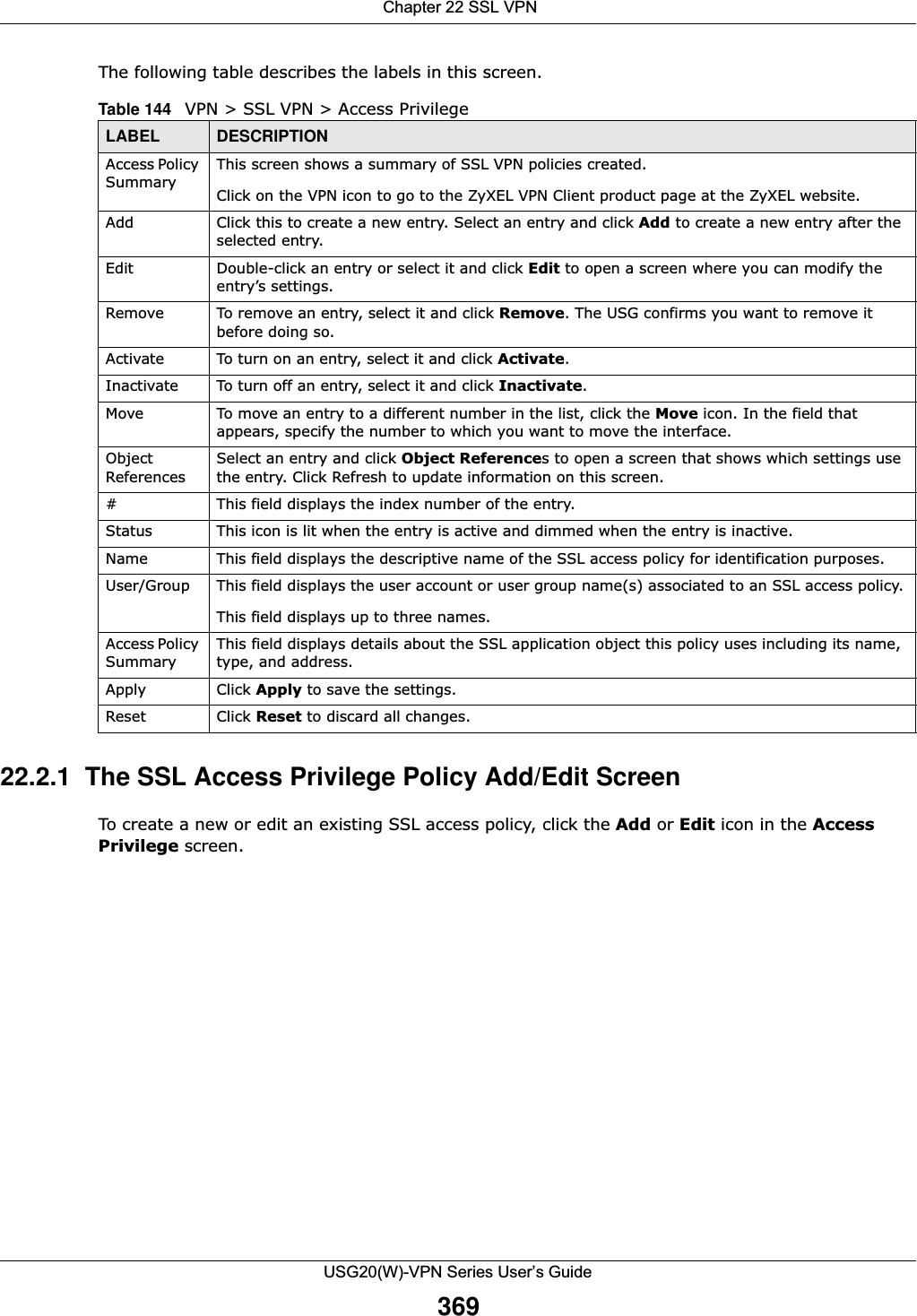
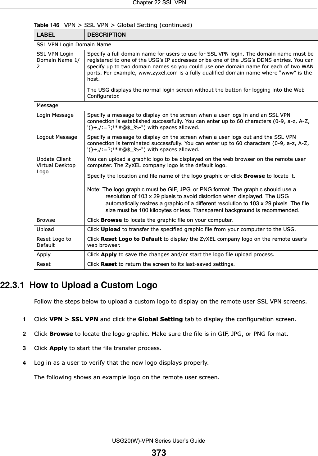
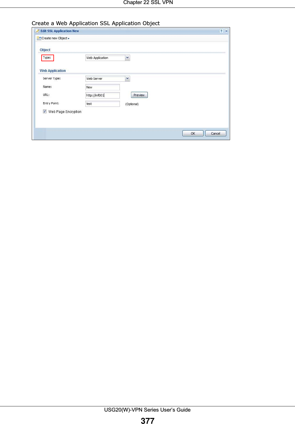
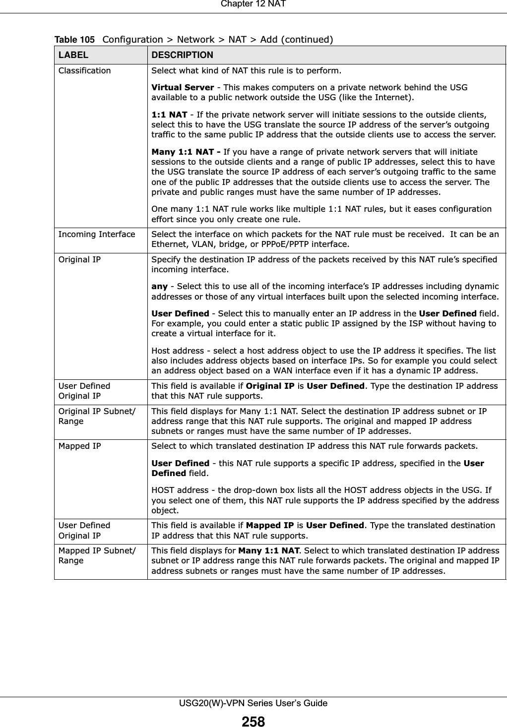
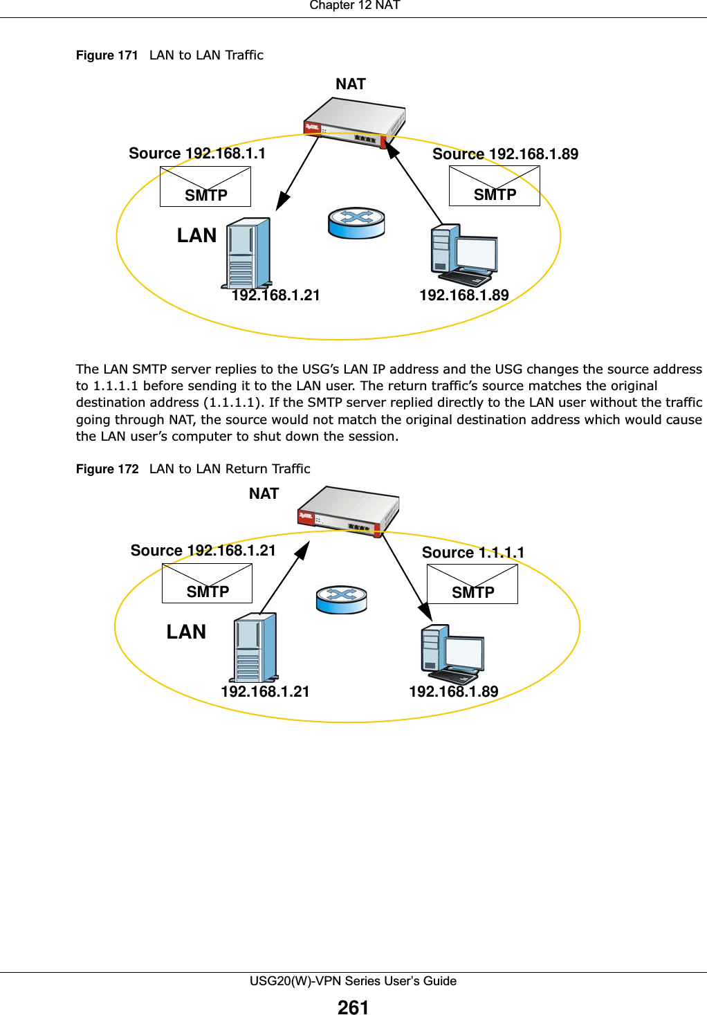
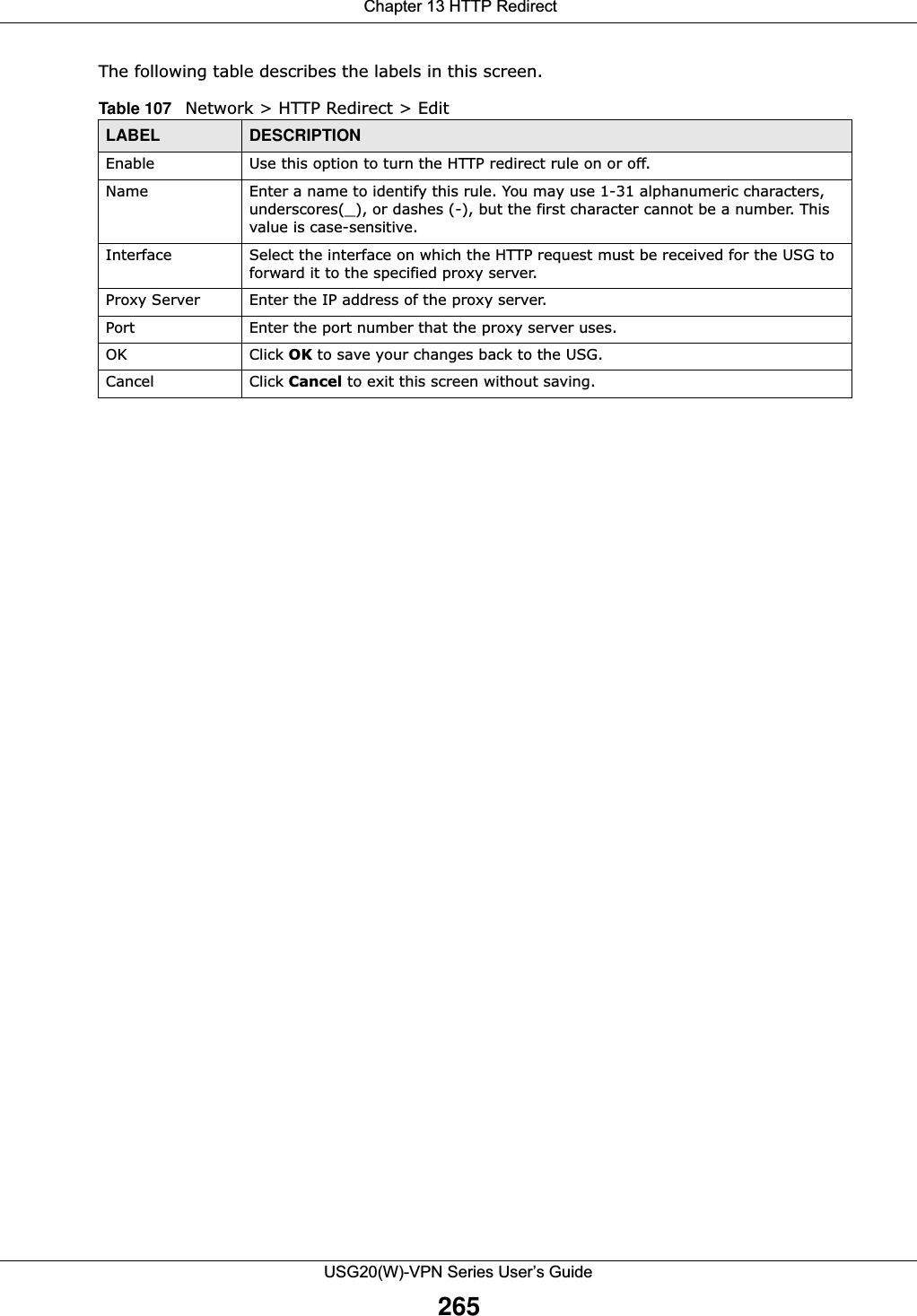
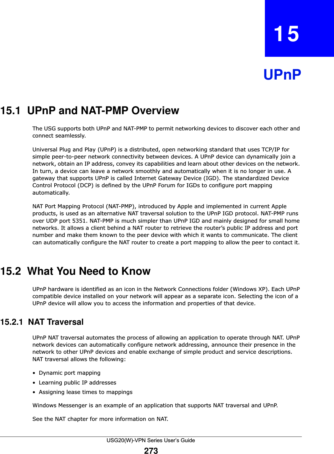
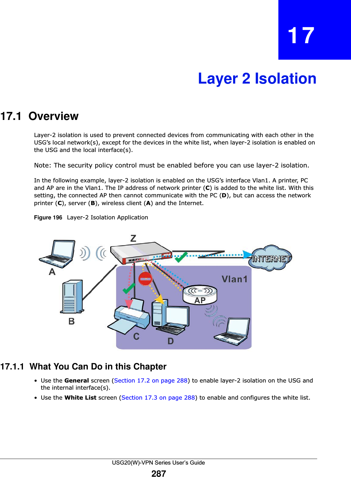
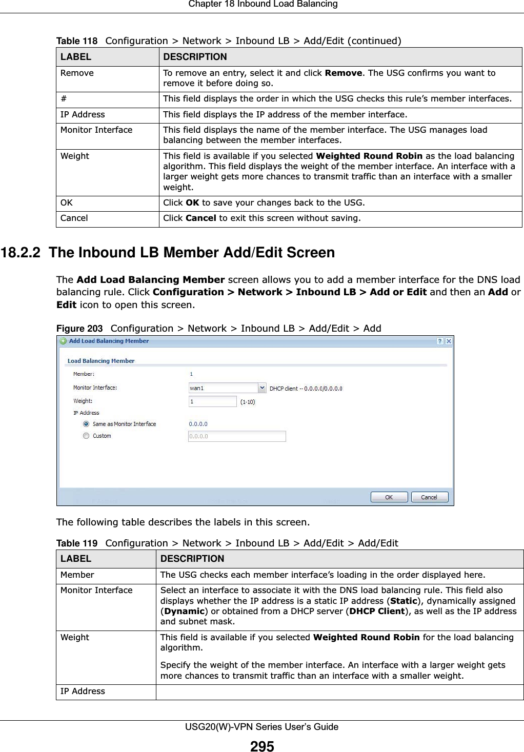
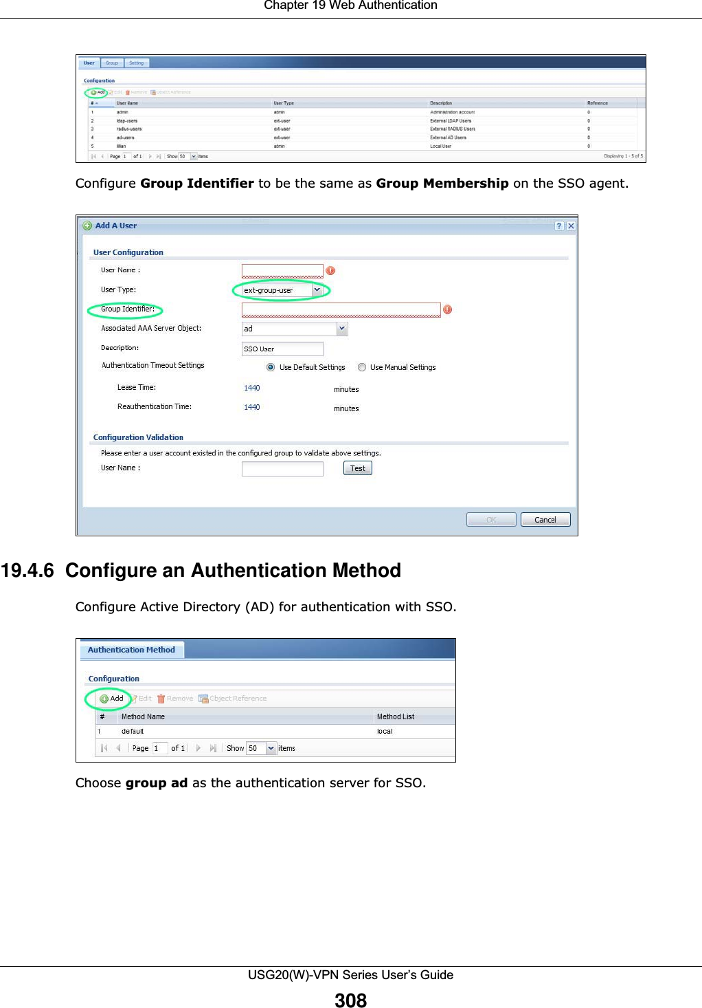
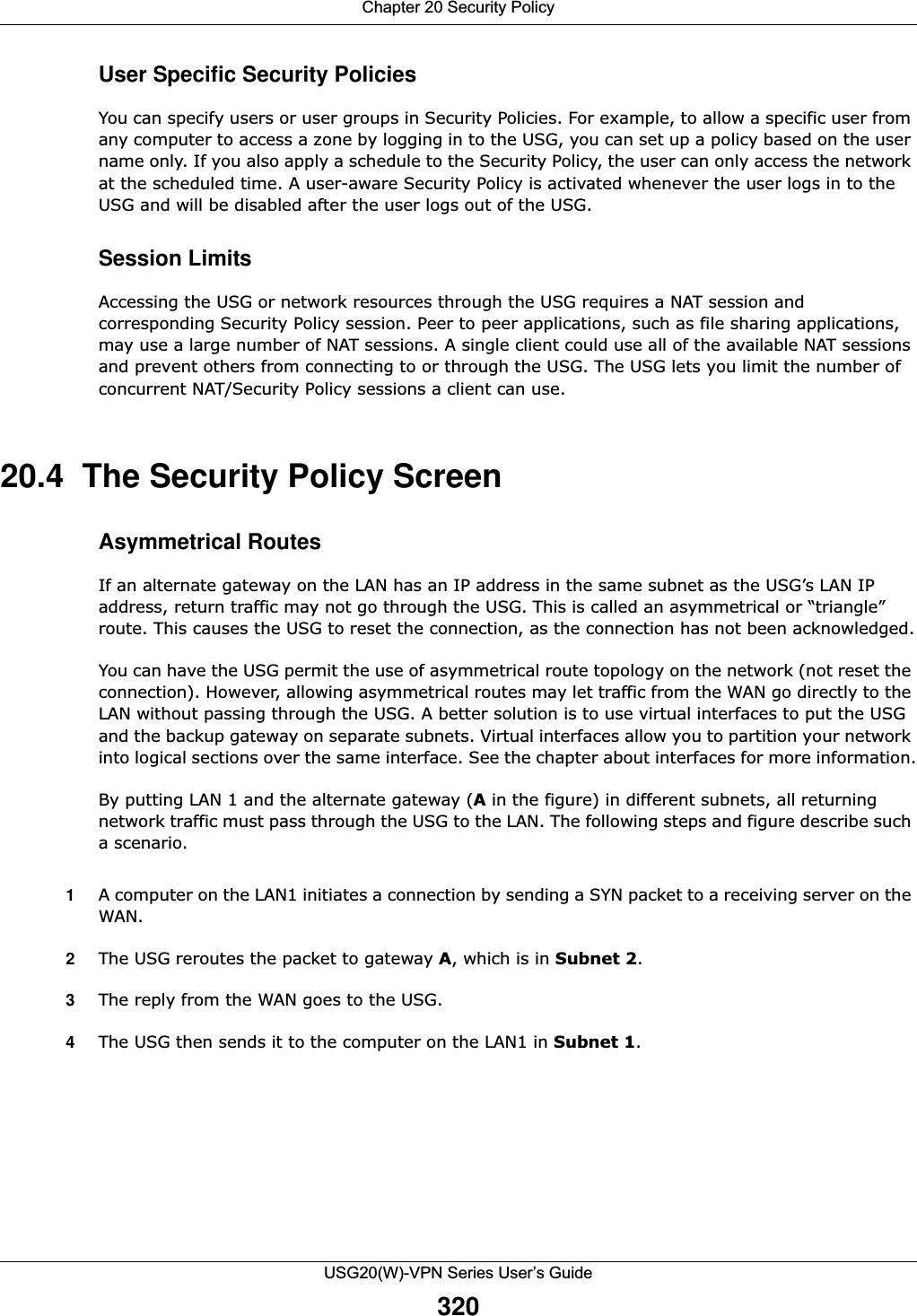
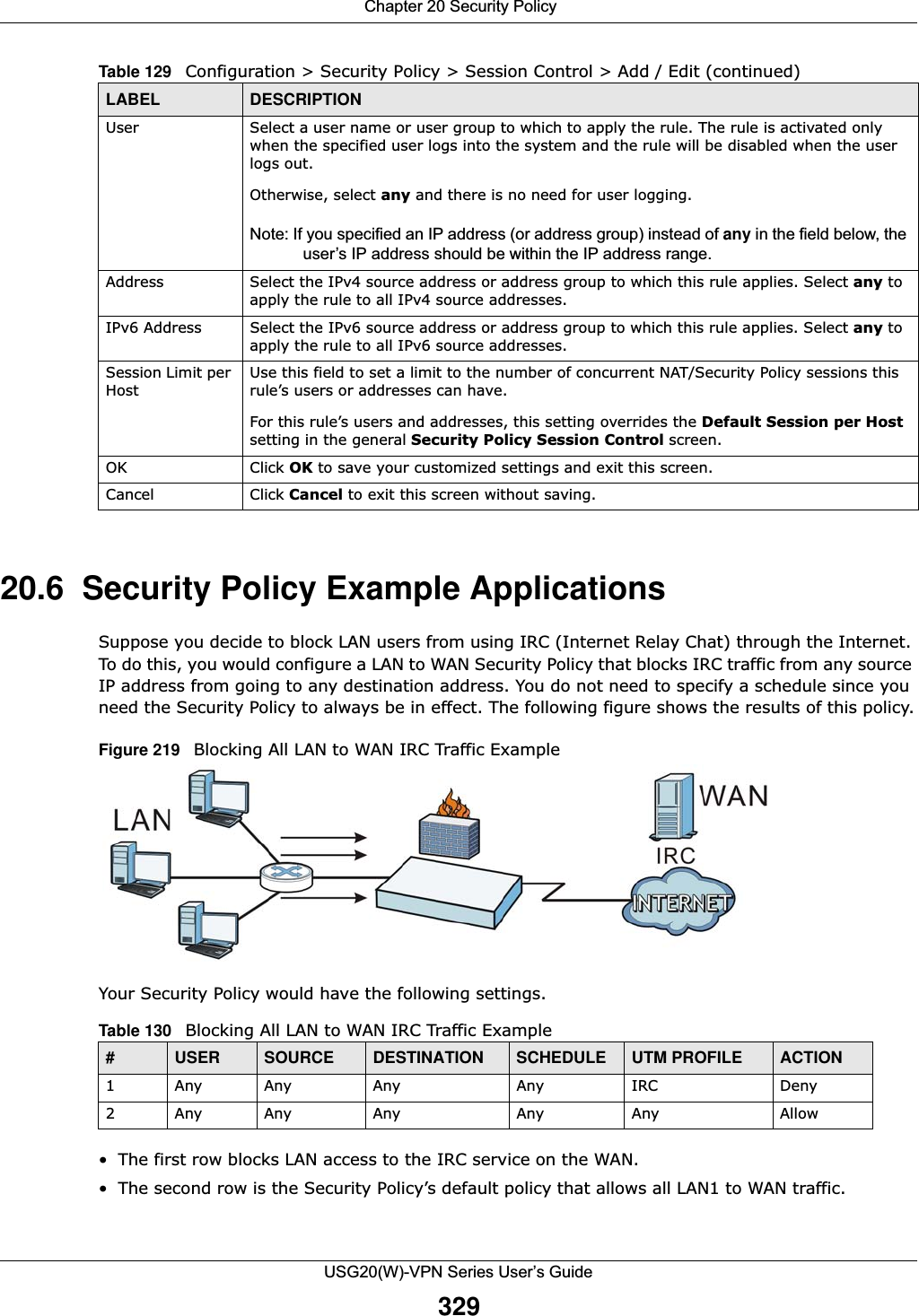
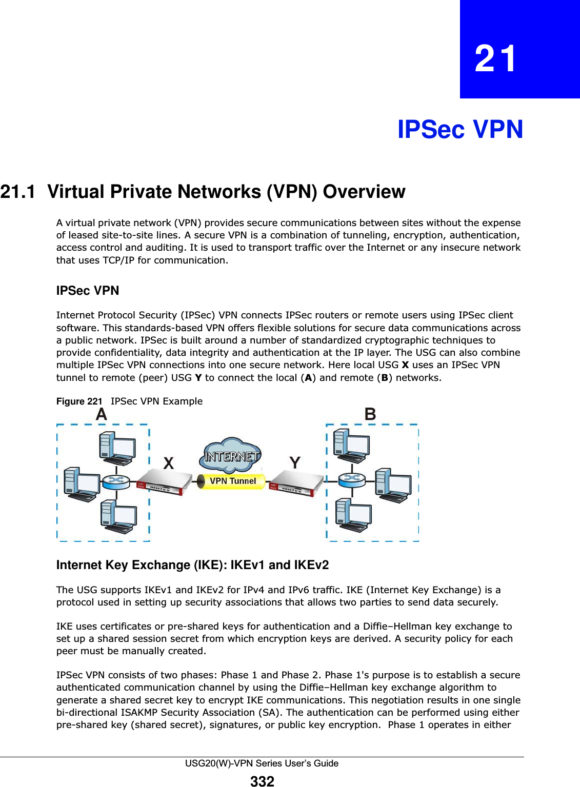
![Chapter 20 Security PolicyUSG20(W)-VPN Series User’s Guide32820.5.1 The Session Control Add/Edit ScreenClick Configuration > Security Policy > Session Control and the Add or Edit icon to display the Add or Edit screen. Use this screen to configure rules that define a session limit for specific users or addresses.Figure 218 Configuration > Security Policy > Session Control > EditThe following table describes the labels in this screen. Remove To remove an entry, select it and click Remove. The USG confirms you want to remove it before doing so.Activate To turn on an entry, select it and click Activate.Inactivate To turn off an entry, select it and click Inactivate.Move To change a rule’s position in the numbered list, select the rule and click Move to display a field to type a number for where you want to put that rule and press [ENTER] to move the rule to the number that you typed.The ordering of your rules is important as they are applied in order of their numbering.Status This icon is lit when the entry is active and dimmed when the entry is inactive.# This is the index number of a session limit rule. It is not associated with a specific rule. User This is the user name or user group name to which this session limit rule applies.IPv4 / IPv6 AddressThis is the IPv4 / IPv6 address object to which this session limit rule applies.Description This is the information configured to help you identify the rule. Limit This is how many concurrent sessions this user or address is allowed to have.Apply Click Apply to save your changes back to the USG.Reset Click Reset to return the screen to its last-saved settings. Table 128 Configuration > Security Policy > Session Control (continued)LABEL DESCRIPTIONTable 129 Configuration > Security Policy > Session Control > Add / EditLABEL DESCRIPTIONCreate new ObjectUse to configure new settings for User or Address objects that you need to use in this screen.Click on the down arrow to see the menu.Enable Rule Select this check box to turn on this session limit rule. Description Enter information to help you identify this rule. Use up to 60 printable ASCII characters. Spaces are allowed.](https://usermanual.wiki/ZyXEL-Communications/USG20W-VPN.Users-Manual-Part-3/User-Guide-2904715-Page-74.png)
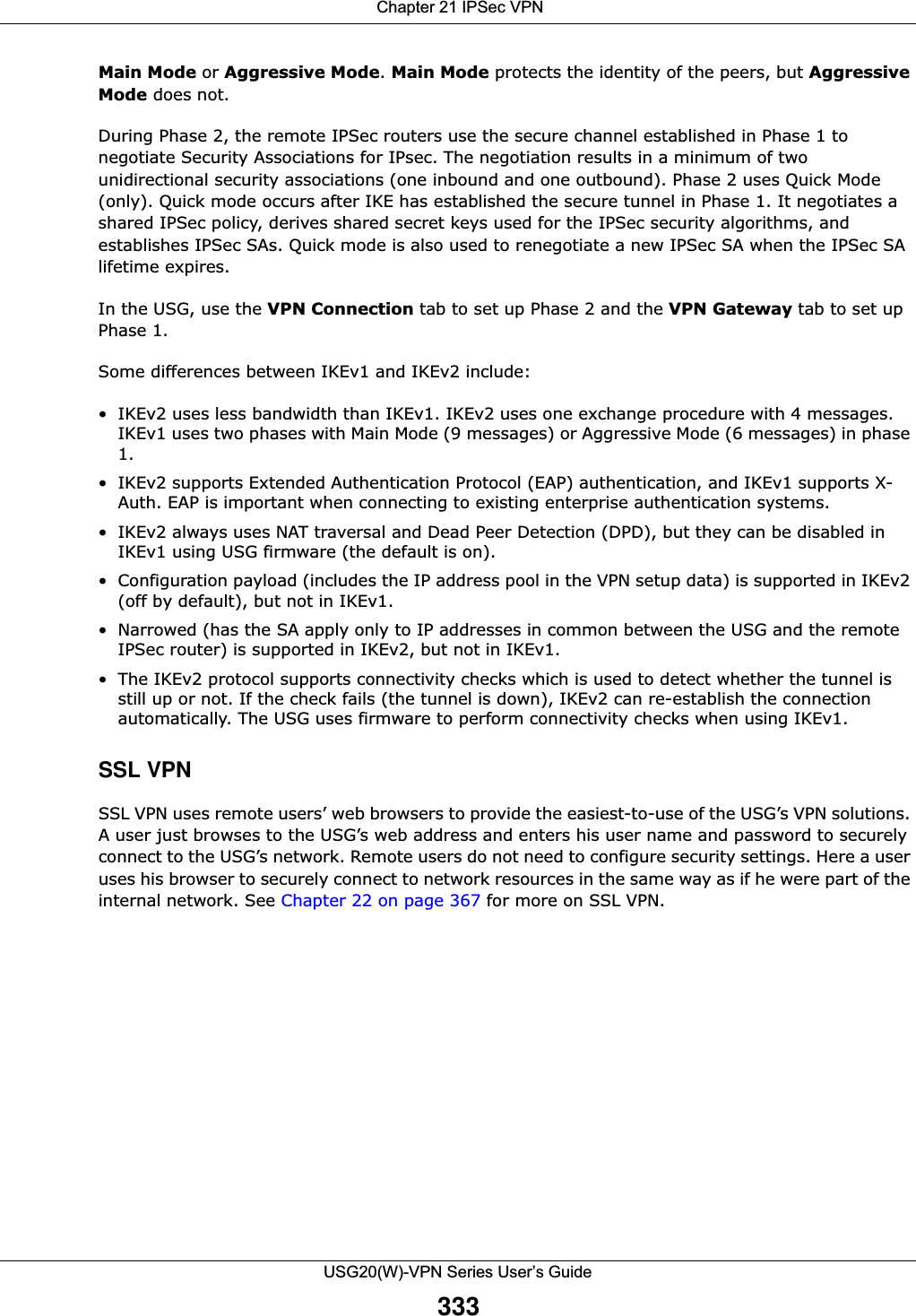
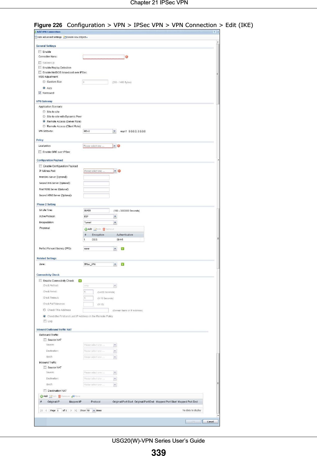
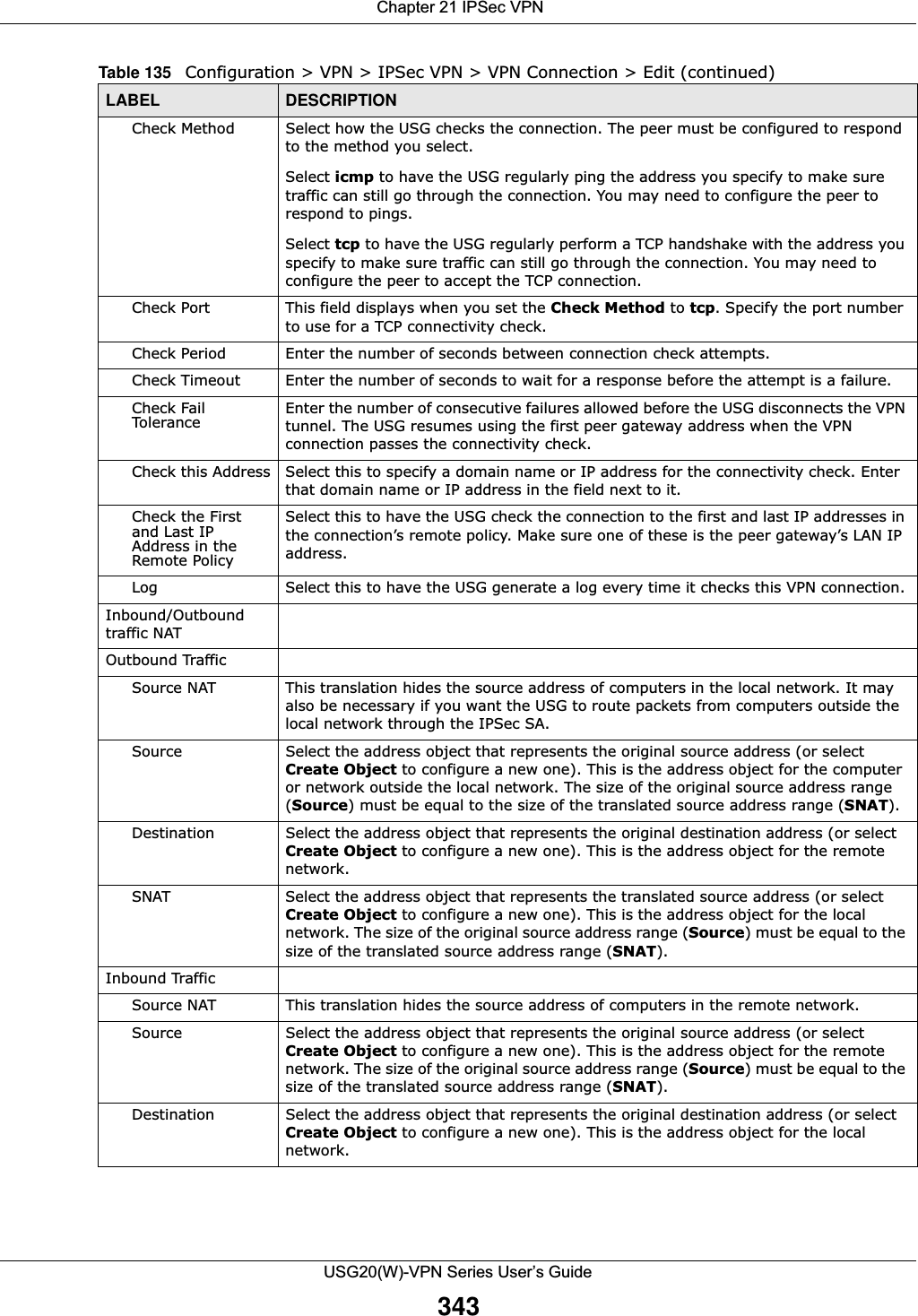
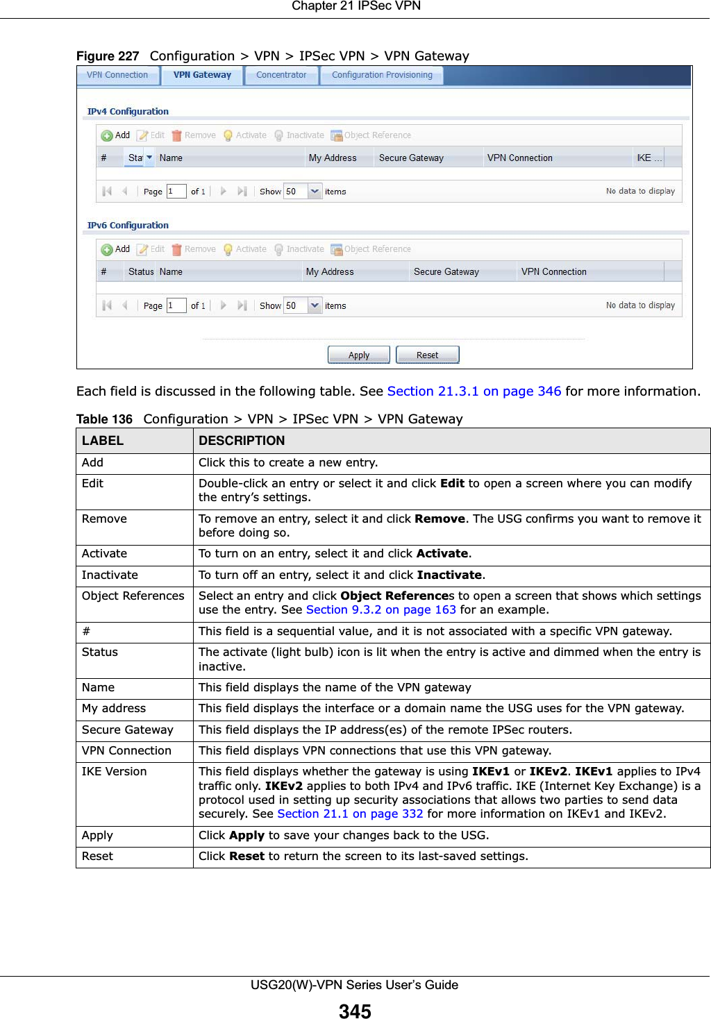
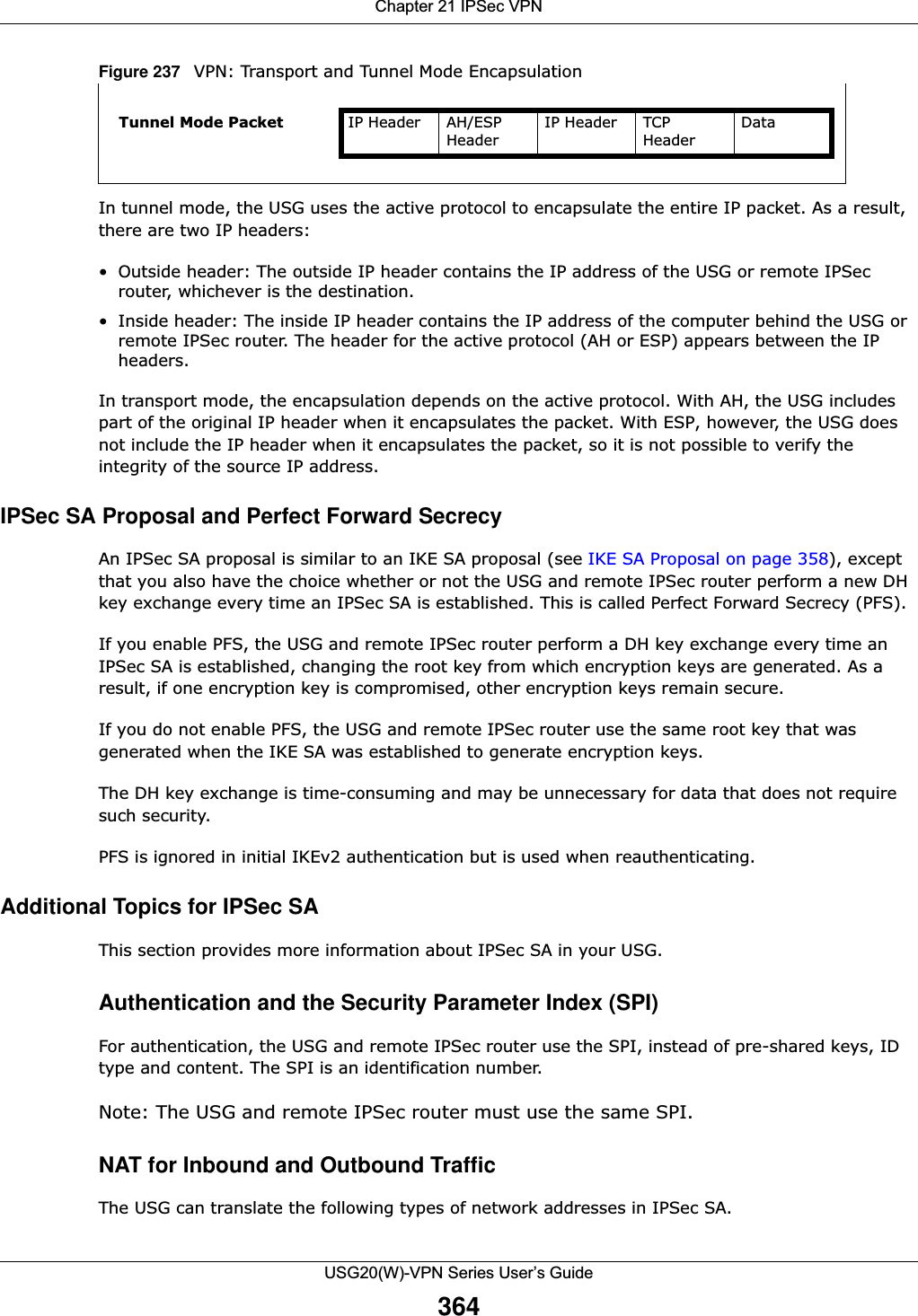
![Chapter 21 IPSec VPNUSG20(W)-VPN Series User’s Guide34421.3 The VPN Gateway ScreenThe VPN Gateway summary screen displays the IPSec VPN gateway policies in the USG, as well as the USG’s address, remote IPSec router’s address, and associated VPN connections for each one. In addition, it also lets you activate and deactivate each VPN gateway. To access this screen, click Configuration > VPN > Network > IPSec VPN > VPN Gateway. The following screen appears.SNAT Select the address object that represents the translated source address (or select Create Object to configure a new one). This is the address that hides the original source address. The size of the original source address range (Source) must be equal to the size of the translated source address range (SNAT).Destination NAT This translation forwards packets (for example, mail) from the remote network to a specific computer (for example, the mail server) in the local network.Add Click this to create a new entry. Select an entry and click Add to create a new entry after the selected entry.Edit Select an entry and click this to be able to modify it. Remove Select an entry and click this to delete it. Move To change an entry’s position in the numbered list, select it and click Move to display a field to type a number for where you want to put that entry and press [ENTER] to move the entry to the number that you typed.# This field is a sequential value, and it is not associated with a specific NAT record. However, the order of records is the sequence in which conditions are checked and executed.Original IP Select the address object that represents the original destination address. This is the address object for the remote network.Mapped IP Select the address object that represents the desired destination address. For example, this is the address object for the mail server.Protocol Select the protocol required to use this translation. Choices are: TCP, UDP, or All.Original Port Start / Original Port End These fields are available if the protocol is TCP or UDP. Enter the original destination port or range of original destination ports. The size of the original port range must be the same size as the size of the mapped port range.Mapped Port Start / Mapped Port End These fields are available if the protocol is TCP or UDP. Enter the translated destination port or range of translated destination ports. The size of the original port range must be the same size as the size of the mapped port range.OK Click OK to save the changes. Cancel Click Cancel to discard all changes and return to the main VPN screen. Table 135 Configuration > VPN > IPSec VPN > VPN Connection > Edit (continued)LABEL DESCRIPTION](https://usermanual.wiki/ZyXEL-Communications/USG20W-VPN.Users-Manual-Part-3/User-Guide-2904715-Page-90.png)
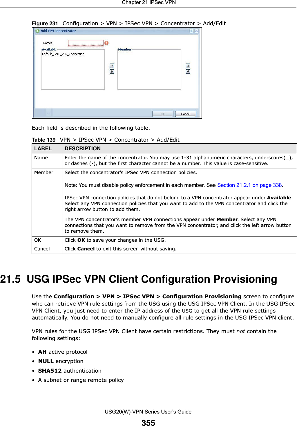
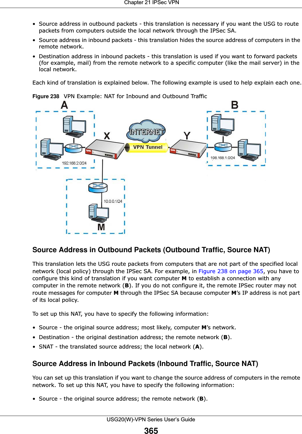
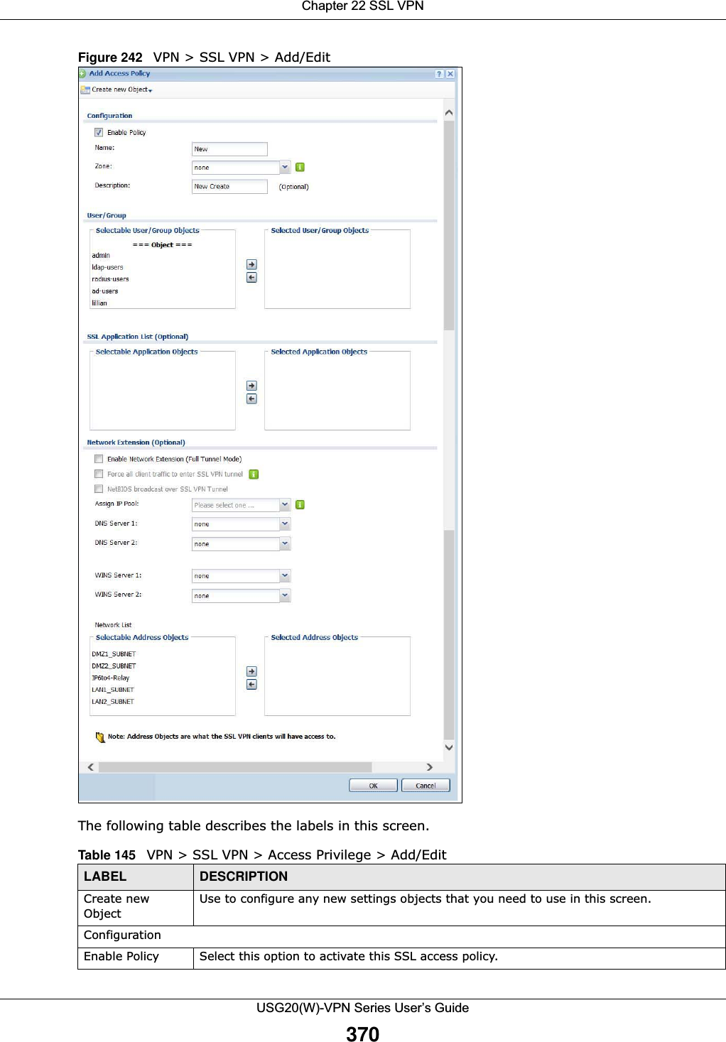
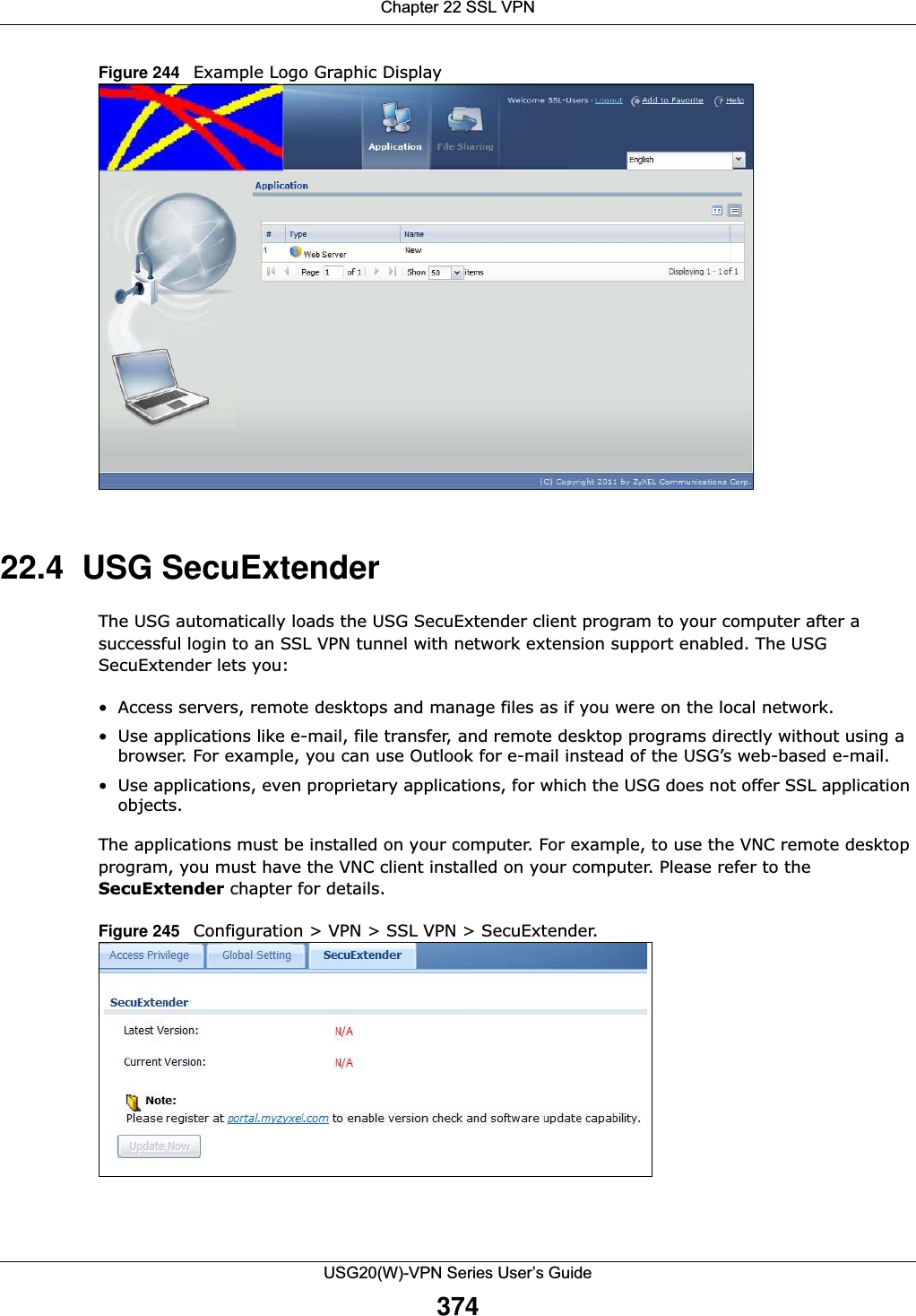
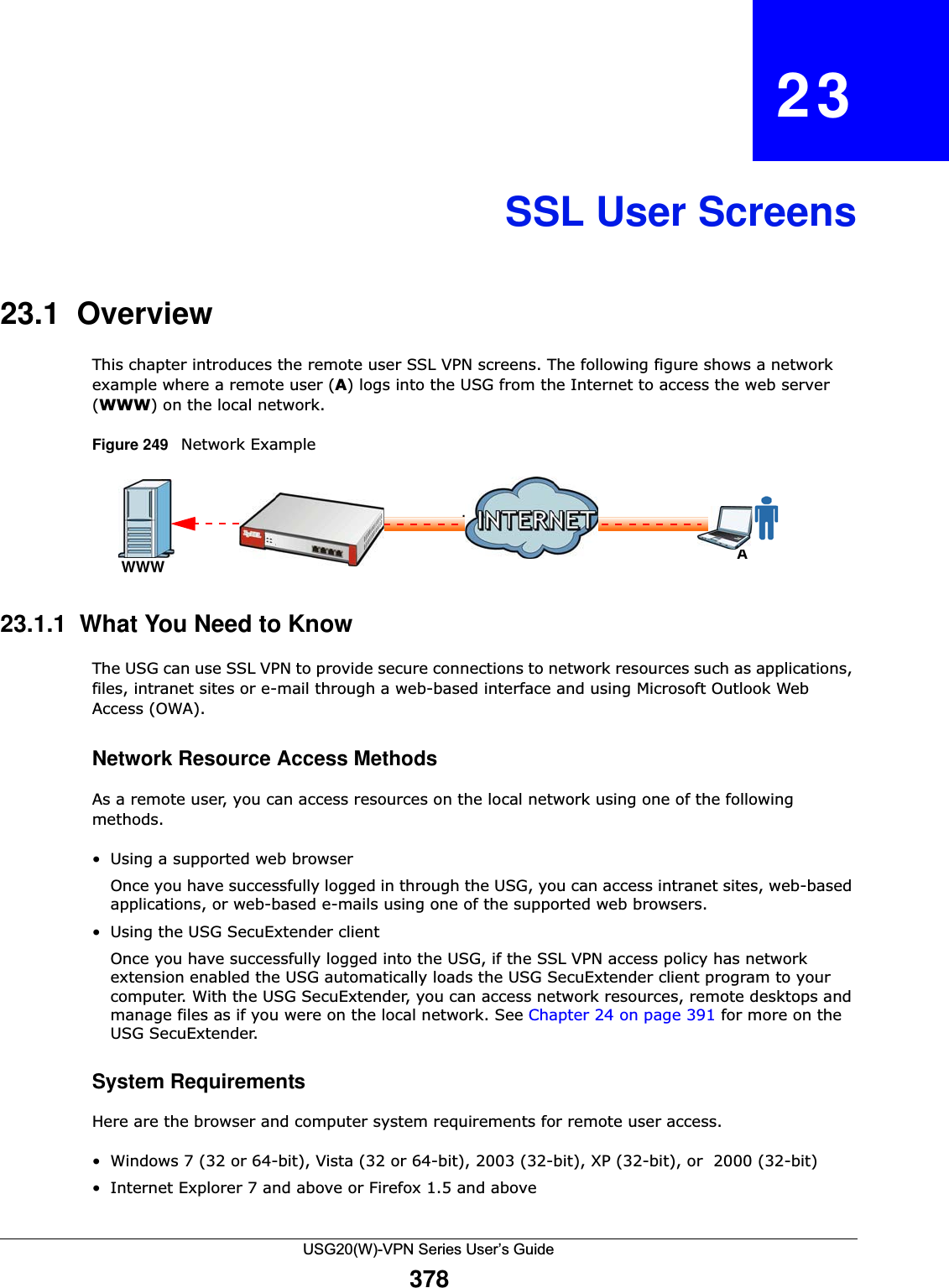
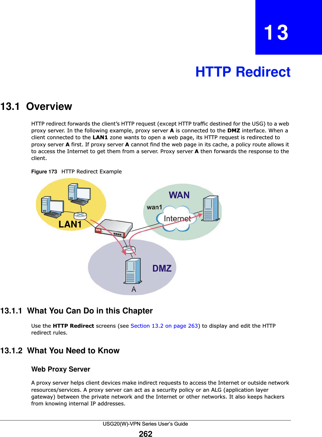
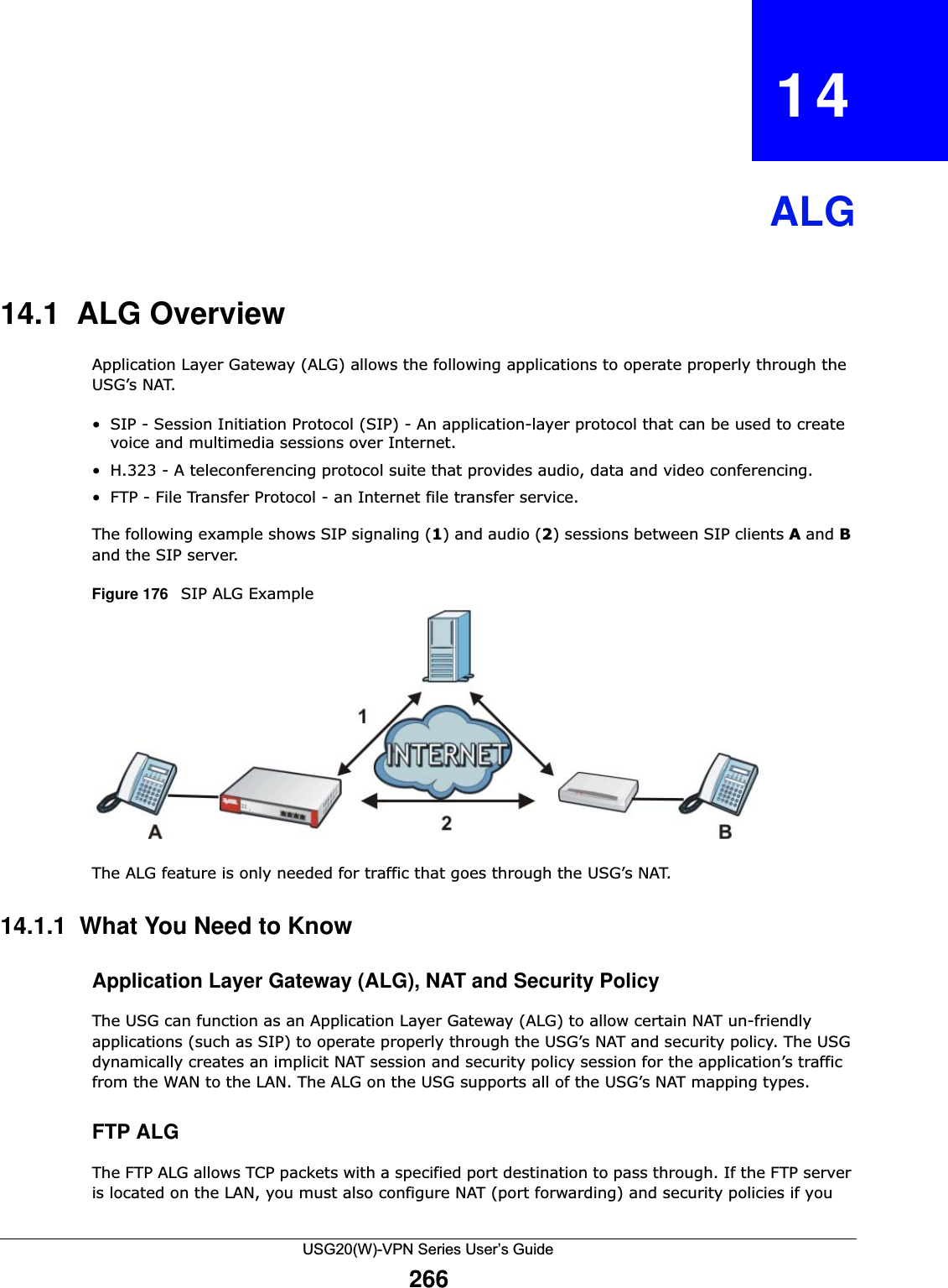
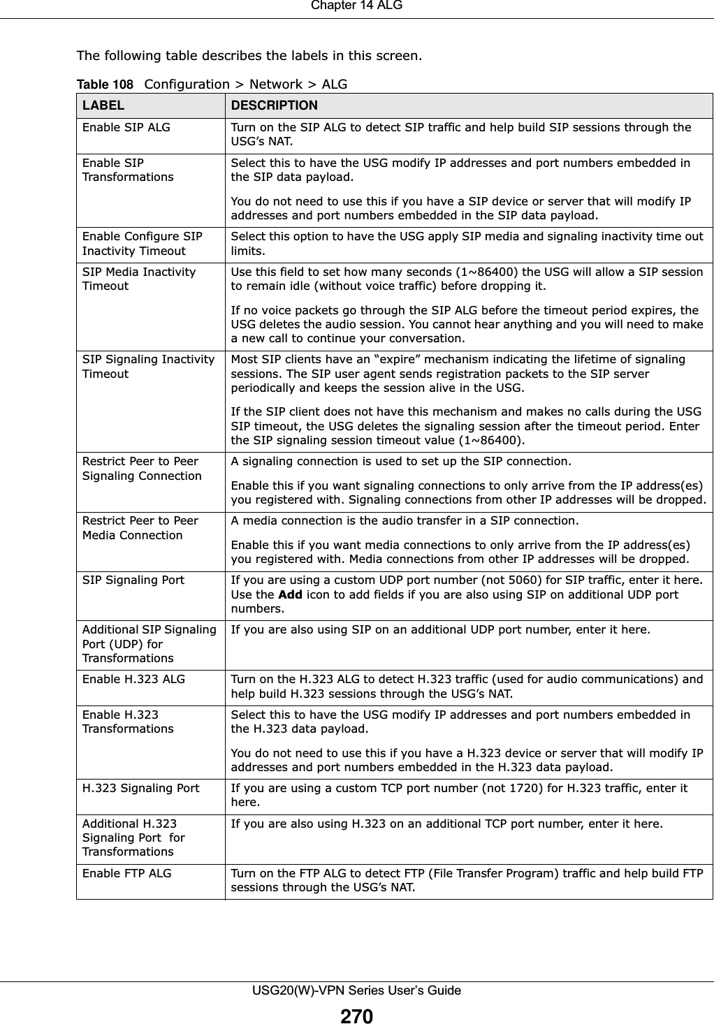
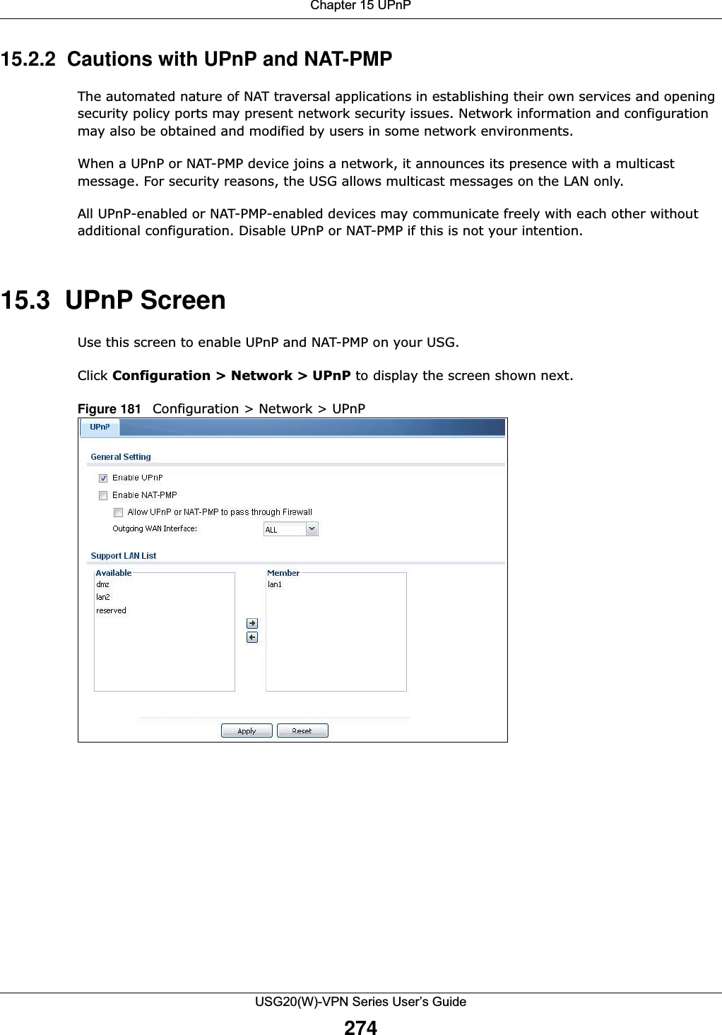
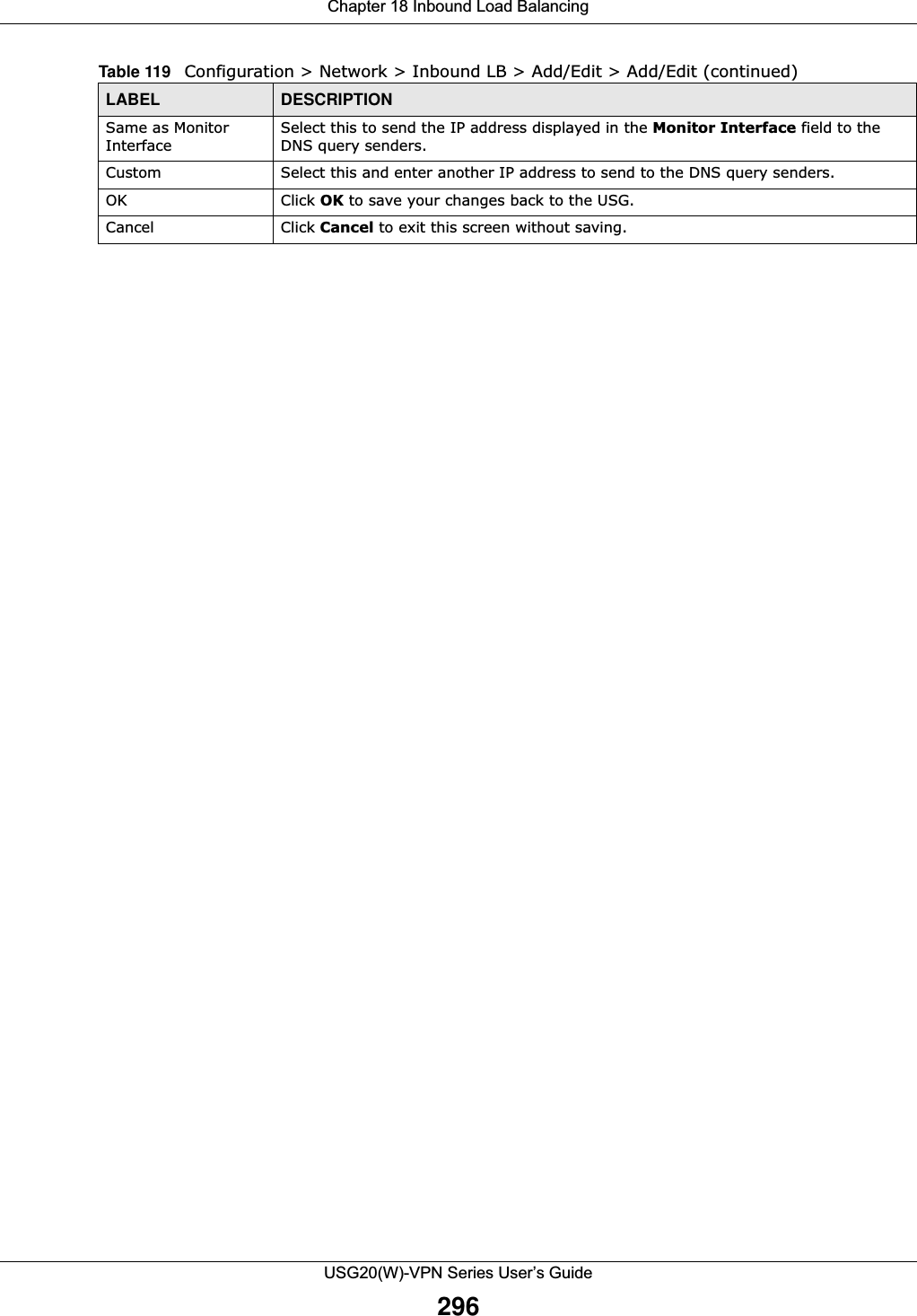
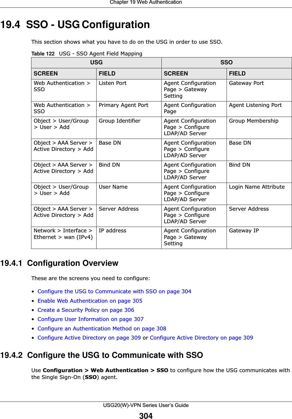
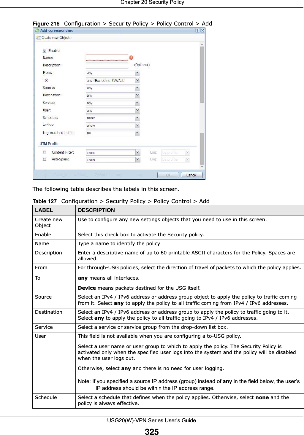
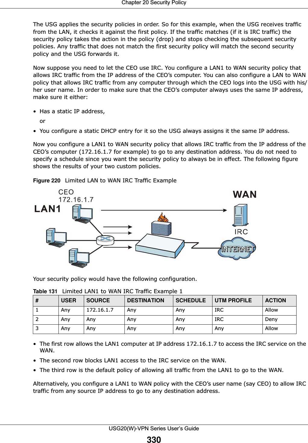
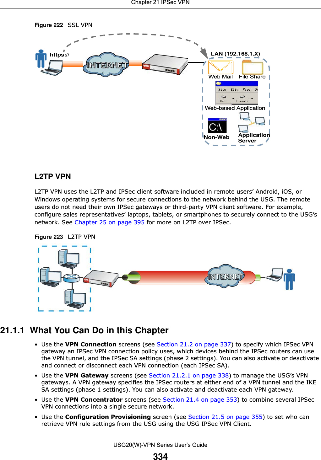
![Chapter 21 IPSec VPNUSG20(W)-VPN Series User’s Guide366• Destination - the original destination address; the local network (A).• SNAT - the translated source address; a different IP address (range of addresses) to hide the original source address.Destination Address in Inbound Packets (Inbound Traffic, Destination NAT)You can set up this translation if you want the USG to forward some packets from the remote network to a specific computer in the local network. For example, in Figure 238 on page 365, you can configure this kind of translation if you want to forward mail from the remote network to the mail server in the local network (A).You have to specify one or more rules when you set up this kind of NAT. The USG checks these rules similar to the way it checks rules for a security policy. The first part of these rules define the conditions in which the rule apply.• Original IP - the original destination address; the remote network (B).• Protocol - the protocol [TCP, UDP, or both] used by the service requesting the connection.• Original Port - the original destination port or range of destination ports; in Figure 238 on page 365, it might be port 25 for SMTP.The second part of these rules controls the translation when the condition is satisfied.• Mapped IP - the translated destination address; in Figure 238 on page 365, the IP address of the mail server in the local network (A).• Mapped Port - the translated destination port or range of destination ports.The original port range and the mapped port range must be the same size.IPSec VPN Example ScenarioHere is an example site-to-site IPSec VPN scenario.Figure 239 Site-to-site IPSec VPN Example192.168.1.0/24 172.16.1.0/241.2.3.4 2.2.2.2LAN LAN](https://usermanual.wiki/ZyXEL-Communications/USG20W-VPN.Users-Manual-Part-3/User-Guide-2904715-Page-112.png)