ZyXEL Communications USG20W-VPN VPN Firewall User Manual Book
ZyXEL Communications Corporation VPN Firewall Book
Contents
- 1. Users Manual Part 1
- 2. Users Manual Part 2
- 3. Users Manual Part 3
- 4. Users Manual Part 4
- 5. Users Manual Part 5
Users Manual Part 3
USG20(W)-VPN Series User’s Guide
255
CHAPTER 12
NAT
12.1 NAT Overview
NAT (Network Address Translation - NAT, RFC 1631) is the translation of the IP address of a host in
a packet. For example, the source address of an outgoing packet, used within one network is
changed to a different IP address known within another network. Use Network Address Translation
(NAT) to make computers on a private network behind the USG available outside the private
network. If the USG has only one public IP address, you can make the computers in the private
network available by using ports to forward packets to the appropriate private IP address.
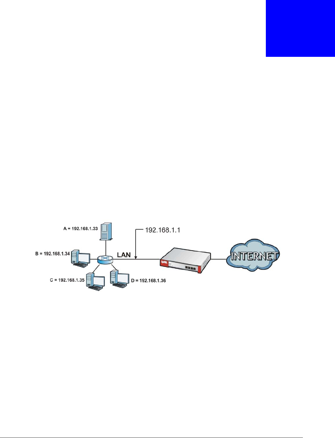
Suppose you want to assign ports 21-25 to one FTP, Telnet and SMTP server (A in the example),
port 80 to another (B in the example) and assign a default server IP address of 192.168.1.35 to a
third (C in the example). You assign the LAN IP addresses and the ISP assigns the WAN IP address.
The NAT network appears as a single host on the Internet.
Figure 167 Multiple Servers Behind NAT Example
12.1.1 What You Can Do in this Chapter
Use the NAT screens (see Section 12.2 on page 255) to view and manage the list of NAT rules and
see their configuration details. You can also create new NAT rules and edit or delete existing ones.
12.1.2 What You Need to Know
NAT is also known as virtual server, port forwarding, or port translation.
12.2 The NAT Screen
The NAT summary screen provides a summary of all NAT rules and their configuration. In addition,
this screen allows you to create new NAT rules and edit and delete existing NAT rules. To access this
Chapter 12 NAT
USG20(W)-VPN Series User’s Guide
256
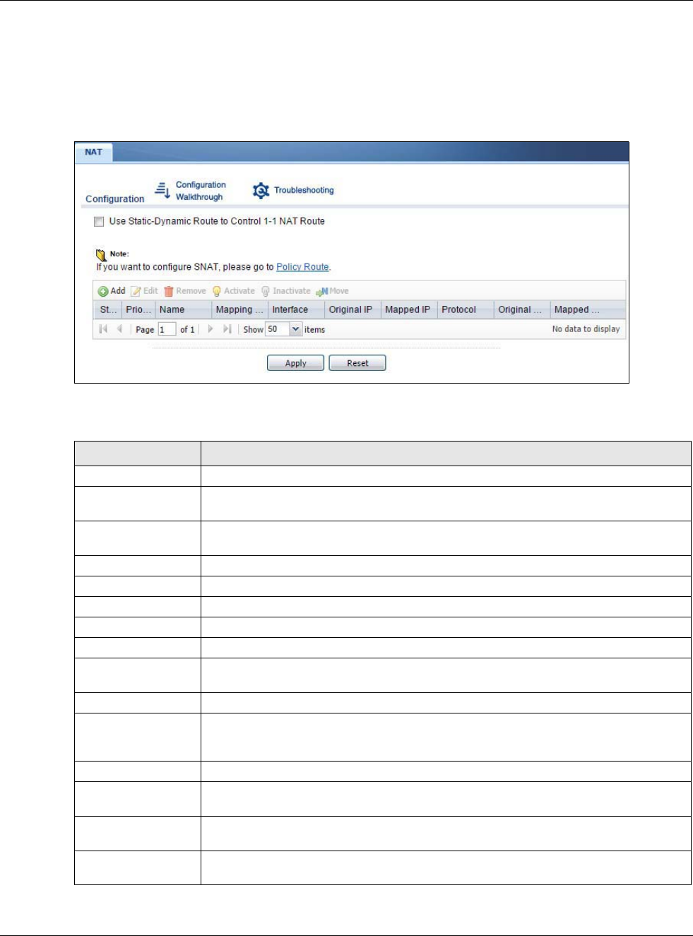
screen, login to the Web Configurator and click Configuration > Network > NAT. The following
screen appears, providing a summary of the existing NAT rules.
Click on the icons to go to the OneSecurity.com website where there is guidance on configuration
walkthroughs, troubleshooting, and other information.
Figure 168 Configuration > Network > NAT
The following table describes the labels in this screen.
Table 104 Configuration > Network > NAT
LABEL DESCRIPTION
Add Click this to create a new entry.
Edit Double-click an entry or select it and click Edit to open a screen where you can modify
the entry’s settings.
Remove To remove an entry, select it and click Remove. The USG confirms you want to remove
it before doing so.
Activate To turn on an entry, select it and click Activate.
Inactivate To turn off an entry, select it and click Inactivate.
# This field is a sequential value, and it is not associated with a specific entry.
Status This icon is lit when the entry is active and dimmed when the entry is inactive.
Name This field displays the name of the entry.
Mapping Type This field displays what kind of NAT this entry performs: Virtual Server, 1:1 NAT, or
Many 1:1 NAT.
Interface This field displays the interface on which packets for the NAT entry are received.
Original IP This field displays the original destination IP address (or address object) of traffic that
matches this NAT entry. It displays any if there is no restriction on the original
destination IP address.
Mapped IP This field displays the new destination IP address for the packet.
Protocol This field displays the service used by the packets for this NAT entry. It displays any if
there is no restriction on the services.
Original Port This field displays the original destination port(s) of packets for the NAT entry. This
field is blank if there is no restriction on the original destination port.
Mapped Port This field displays the new destination port(s) for the packet. This field is blank if there
is no restriction on the original destination port.
Chapter 12 NAT
USG20(W)-VPN Series User’s Guide
257
12.2.1 The NAT Add/Edit Screen
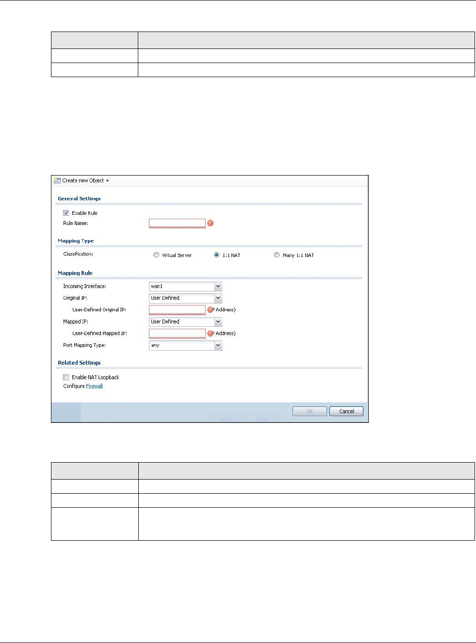
The NAT Add/Edit screen lets you create new NAT rules and edit existing ones. To open this
window, open the NAT summary screen. (See Section 12.2 on page 255.) Then, click on an Add
icon or Edit icon to open the following screen.
Figure 169 Configuration > Network > NAT > Add
The following table describes the labels in this screen.
Apply Click this button to save your changes to the USG.
Reset Click this button to return the screen to its last-saved settings.
Table 104 Configuration > Network > NAT (continued)
LABEL DESCRIPTION
Table 105 Configuration > Network > NAT > Add
LABEL DESCRIPTION
Create new Object Use to configure any new settings objects that you need to use in this screen.
Enable Rule Use this option to turn the NAT rule on or off.
Rule Name Type in the name of the NAT rule. The name is used to refer to the NAT rule. You may
use 1-31 alphanumeric characters, underscores(_), or dashes (-), but the first
character cannot be a number. This value is case-sensitive.

Chapter 12 NAT
USG20(W)-VPN Series User’s Guide
258
Classification Select what kind of NAT this rule is to perform.
Virtual Server - This makes computers on a private network behind the USG
available to a public network outside the USG (like the Internet).
1:1 NAT - If the private network server will initiate sessions to the outside clients,
select this to have the USG translate the source IP address of the server’s outgoing
traffic to the same public IP address that the outside clients use to access the server.
Many 1:1 NAT - If you have a range of private network servers that will initiate
sessions to the outside clients and a range of public IP addresses, select this to have
the USG translate the source IP address of each server’s outgoing traffic to the same
one of the public IP addresses that the outside clients use to access the server. The
private and public ranges must have the same number of IP addresses.
One many 1:1 NAT rule works like multiple 1:1 NAT rules, but it eases configuration
effort since you only create one rule.
Incoming Interface Select the interface on which packets for the NAT rule must be received. It can be an
Ethernet, VLAN, bridge, or PPPoE/PPTP interface.
Original IP Specify the destination IP address of the packets received by this NAT rule’s specified
incoming interface.
any - Select this to use all of the incoming interface’s IP addresses including dynamic
addresses or those of any virtual interfaces built upon the selected incoming interface.
User Defined - Select this to manually enter an IP address in the User Defined field.
For example, you could enter a static public IP assigned by the ISP without having to
create a virtual interface for it.
Host address - select a host address object to use the IP address it specifies. The list
also includes address objects based on interface IPs. So for example you could select
an address object based on a WAN interface even if it has a dynamic IP address.
User Defined
Original IP
This field is available if Original IP is User Defined. Type the destination IP address
that this NAT rule supports.
Original IP Subnet/
Range
This field displays for Many 1:1 NAT. Select the destination IP address subnet or IP
address range that this NAT rule supports. The original and mapped IP address
subnets or ranges must have the same number of IP addresses.
Mapped IP Select to which translated destination IP address this NAT rule forwards packets.
User Defined - this NAT rule supports a specific IP address, specified in the User
Defined field.
HOST address - the drop-down box lists all the HOST address objects in the USG. If
you select one of them, this NAT rule supports the IP address specified by the address
object.
User Defined
Original IP
This field is available if Mapped IP is User Defined. Type the translated destination
IP address that this NAT rule supports.
Mapped IP Subnet/
Range
This field displays for Many 1:1 NAT. Select to which translated destination IP address
subnet or IP address range this NAT rule forwards packets. The original and mapped IP
address subnets or ranges must have the same number of IP addresses.
Table 105 Configuration > Network > NAT > Add (continued)
LABEL DESCRIPTION
Chapter 12 NAT
USG20(W)-VPN Series User’s Guide
259
Port Mapping Type Use the drop-down list box to select how many original destination ports this NAT rule
supports for the selected destination IP address (Original IP). Choices are:
Any - this NAT rule supports all the destination ports.
Port - this NAT rule supports one destination port.
Ports - this NAT rule supports a range of destination ports. You might use a range of
destination ports for unknown services or when one server supports more than one
service.
Service - this NAT rule supports a service such as FTP (see Object > Service >
Service)
Service-Group - this NAT rule supports a group of services such as all service objects
related to DNS (see Object > Service > Service Group)
Protocol Type This field is available if Mapping Type is Port or Ports. Select the protocol (TCP,
UDP, or Any) used by the service requesting the connection.
Original Port This field is available if Mapping Type is Port. Enter the original destination port this
NAT rule supports.
Mapped Port This field is available if Mapping Type is Port. Enter the translated destination port if
this NAT rule forwards the packet.
Original Start Port This field is available if Mapping Type is Ports. Enter the beginning of the range of
original destination ports this NAT rule supports.
Original End Port This field is available if Mapping Type is Ports. Enter the end of the range of original
destination ports this NAT rule supports.
Mapped Start Port This field is available if Mapping Type is Ports. Enter the beginning of the range of
translated destination ports if this NAT rule forwards the packet.
Mapped End Port This field is available if Mapping Type is Ports. Enter the end of the range of
translated destination ports if this NAT rule forwards the packet. The original port
range and the mapped port range must be the same size.
Enable NAT
Loopback
Enable NAT loopback to allow users connected to any interface (instead of just the
specified Incoming Interface) to use the NAT rule’s specified Original IP address to
access the Mapped IP device. For users connected to the same interface as the
Mapped IP device, the USG uses that interface’s IP address as the source address for
the traffic it sends from the users to the Mapped IP device.
For example, if you configure a NAT rule to forward traffic from the WAN to a LAN
server, enabling NAT loopback allows users connected to other interfaces to also
access the server. For LAN users, the USG uses the LAN interface’s IP address as the
source address for the traffic it sends to the LAN server. See NAT Loopback on page
260 for more details.
If you do not enable NAT loopback, this NAT rule only applies to packets received on
the rule’s specified incoming interface.
Security Policy By default the security policy blocks incoming connections from external addresses.
After you configure your NAT rule settings, click the Security Policy link to configure
a security policy to allow the NAT rule’s traffic to come in.
The USG checks NAT rules before it applies To-USG security policies, so To-USG
security policies, do not apply to traffic that is forwarded by NAT rules. The USG still
checks other security policies, according to the source IP address and mapped IP
address.
OK Click OK to save your changes back to the USG.
Cancel Click Cancel to return to the NAT summary screen without creating the NAT rule (if it
is new) or saving any changes (if it already exists).
Table 105 Configuration > Network > NAT > Add (continued)
LABEL DESCRIPTION
Chapter 12 NAT
USG20(W)-VPN Series User’s Guide
260
12.3 NAT Technical Reference
Here is more detailed information about NAT on the USG.
NAT Loopback
Suppose an NAT 1:1 rule maps a public IP address to the private IP address of a LAN SMTP e-mail
server to give WAN users access. NAT loopback allows other users to also use the rule’s original IP
to access the mail server.
For example, a LAN user’s computer at IP address 192.168.1.89 queries a public DNS server to
resolve the SMTP server’s domain name (xxx.LAN-SMTP.com in this example) and gets the SMTP
server’s mapped public IP address of 1.1.1.1.
Figure 170 LAN Computer Queries a Public DNS Server
The LAN user’s computer then sends traffic to IP address 1.1.1.1. NAT loopback uses the IP address
of the USG’s LAN interface (192.168.1.1) as the source address of the traffic going from the LAN
users to the LAN SMTP server.
192.168.1.21
xxx.LAN-SMTP.com = ?
LAN
DNS
192.168.1.89
xxx.LAN-SMTP.com = 1.1.1.1
1.1.1.1
Chapter 12 NAT
USG20(W)-VPN Series User’s Guide
261
Figure 171 LAN to LAN Traffic
The LAN SMTP server replies to the USG’s LAN IP address and the USG changes the source address
to 1.1.1.1 before sending it to the LAN user. The return traffic’s source matches the original
destination address (1.1.1.1). If the SMTP server replied directly to the LAN user without the traffic
going through NAT, the source would not match the original destination address which would cause
the LAN user’s computer to shut down the session.
Figure 172 LAN to LAN Return Traffic
192.168.1.21
LAN
192.168.1.89
Source 192.168.1.89
SMTP
NAT
Source 192.168.1.1
SMTP
192.168.1.21
LAN
192.168.1.89
Source 1.1.1.1
SMTP
NAT
Source 192.168.1.21
SMTP
USG20(W)-VPN Series User’s Guide
262
CHAPTER 13
HTTP Redirect
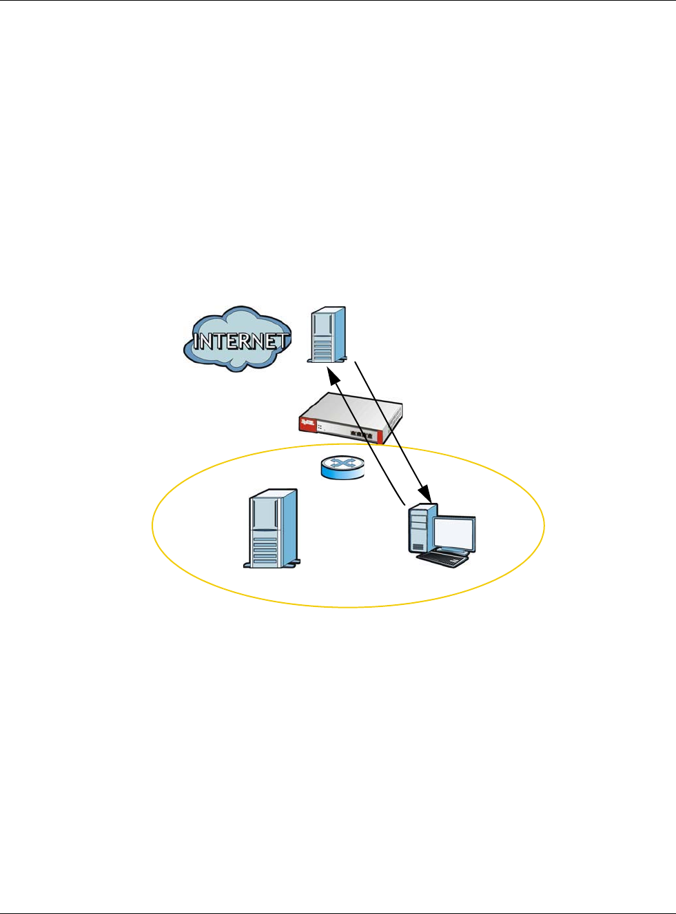
13.1 Overview
HTTP redirect forwards the client’s HTTP request (except HTTP traffic destined for the USG) to a web
proxy server. In the following example, proxy server A is connected to the DMZ interface. When a
client connected to the LAN1 zone wants to open a web page, its HTTP request is redirected to
proxy server A first. If proxy server A cannot find the web page in its cache, a policy route allows it
to access the Internet to get them from a server. Proxy server A then forwards the response to the
client.
Figure 173 HTTP Redirect Example
13.1.1 What You Can Do in this Chapter
Use the HTTP Redirect screens (see Section 13.2 on page 263) to display and edit the HTTP
redirect rules.
13.1.2 What You Need to Know
Web Proxy Server
A proxy server helps client devices make indirect requests to access the Internet or outside network
resources/services. A proxy server can act as a security policy or an ALG (application layer
gateway) between the private network and the Internet or other networks. It also keeps hackers
from knowing internal IP addresses.
LAN1

Chapter 13 HTTP Redirect
USG20(W)-VPN Series User’s Guide
263
A client connects to a web proxy server each time he/she wants to access the Internet. The web
proxy provides caching service to allow quick access and reduce network usage. The proxy checks
its local cache for the requested web resource first. If it is not found, the proxy gets it from the
specified server and forwards the response to the client.
HTTP Redirect, Security Policy and Policy Route
With HTTP redirect, the relevant packet flow for HTTP traffic is:
1Security Policy
2HTTP Redirect
3Policy Route
Even if you set a policy route to the same incoming interface and service as a HTTP redirect rule,
the USG checks the HTTP redirect rules first and forwards HTTP traffic to a proxy server if matched.
You need to make sure there is no security policy(s) blocking the HTTP requests from the client to
the proxy server.
You also need to manually configure a policy route to forward the HTTP traffic from the proxy server
to the Internet. To make the example in Figure 173 on page 262 work, make sure you have the
following settings.
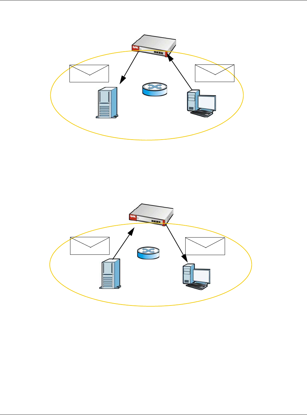
For HTTP traffic between lan1 and dmz:
• a from LAN1 to DMZ security policy (default) to allow HTTP requests from lan1 to dmz.
Responses to this request are allowed automatically.
• a HTTP redirect rule to forward HTTP traffic from lan1 to proxy server A.
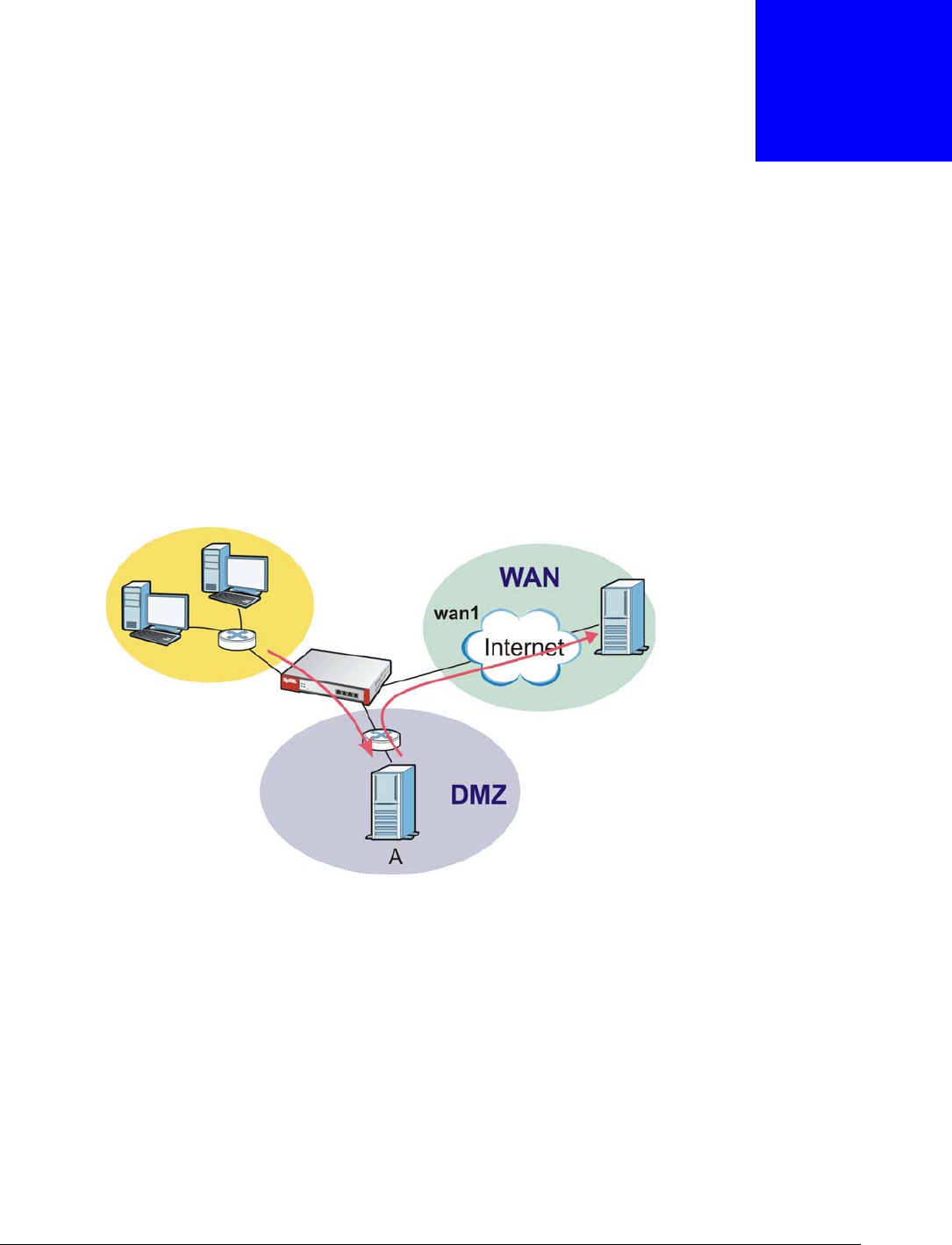
For HTTP traffic between dmz and wan1:
• a from DMZ to WAN security policy (default) to allow HTTP requests from dmz to wan1.
Responses to these requests are allowed automatically.
• a policy route to forward HTTP traffic from proxy server A to the Internet.
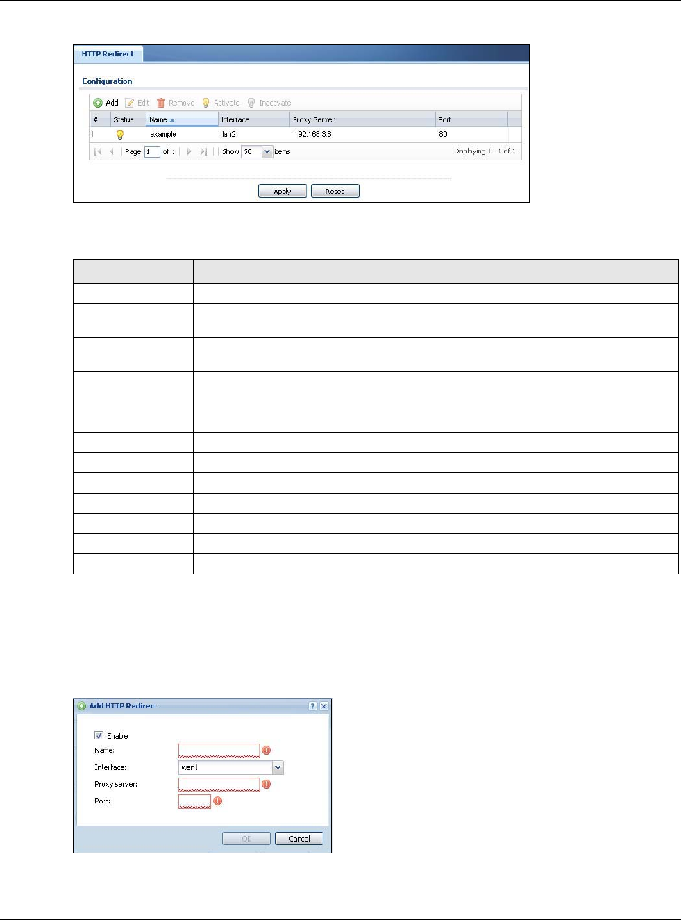
13.2 The HTTP Redirect Screen
To configure redirection of a HTTP request to a proxy server, click Configuration > Network >
HTTP Redirect. This screen displays the summary of the HTTP redirect rules.
Note: You can configure up to one HTTP redirect rule for each (incoming) interface.
Chapter 13 HTTP Redirect
USG20(W)-VPN Series User’s Guide
264
Figure 174 Configuration > Network > HTTP Redirect
The following table describes the labels in this screen.
13.2.1 The HTTP Redirect Edit Screen
Click Network > HTTP Redirect to open the HTTP Redirect screen. Then click the Add or Edit
icon to open the HTTP Redirect Edit screen where you can configure the rule.
Figure 175 Network > HTTP Redirect > Edit
Table 106 Configuration > Network > HTTP Redirect
LABEL DESCRIPTION
Add Click this to create a new entry.
Edit Double-click an entry or select it and click Edit to open a screen where you can modify
the entry’s settings.
Remove To remove an entry, select it and click Remove. The USG confirms you want to remove
it before doing so.
Activate To turn on an entry, select it and click Activate.
Inactivate To turn off an entry, select it and click Inactivate.
# This field is a sequential value, and it is not associated with a specific entry.
Status This icon is lit when the entry is active and dimmed when the entry is inactive.
Name This is the descriptive name of a rule.
Interface This is the interface on which the request must be received.
Proxy Server This is the IP address of the proxy server.
Port This is the service port number used by the proxy server.
Apply Click Apply to save your changes back to the USG.
Reset Click Reset to return the screen to its last-saved settings.
Chapter 13 HTTP Redirect
USG20(W)-VPN Series User’s Guide
265
The following table describes the labels in this screen.
Table 107 Network > HTTP Redirect > Edit
LABEL DESCRIPTION
Enable Use this option to turn the HTTP redirect rule on or off.
Name Enter a name to identify this rule. You may use 1-31 alphanumeric characters,
underscores(_), or dashes (-), but the first character cannot be a number. This
value is case-sensitive.
Interface Select the interface on which the HTTP request must be received for the USG to
forward it to the specified proxy server.
Proxy Server Enter the IP address of the proxy server.
Port Enter the port number that the proxy server uses.
OK Click OK to save your changes back to the USG.
Cancel Click Cancel to exit this screen without saving.
USG20(W)-VPN Series User’s Guide
266
CHAPTER 14
ALG
14.1 ALG Overview
Application Layer Gateway (ALG) allows the following applications to operate properly through the
USG’s NAT.
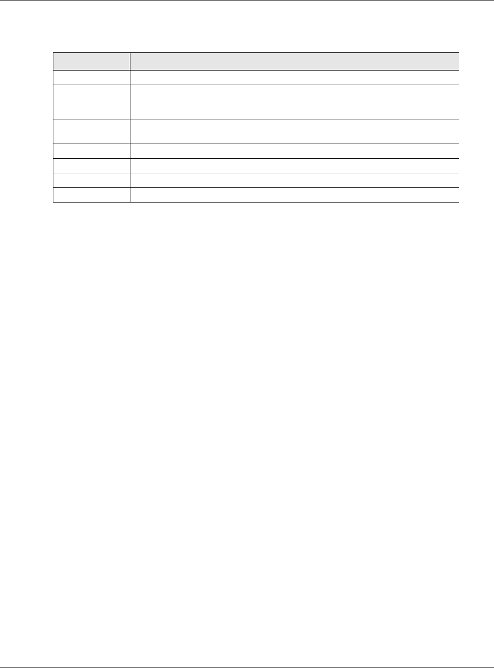
• SIP - Session Initiation Protocol (SIP) - An application-layer protocol that can be used to create
voice and multimedia sessions over Internet.
• H.323 - A teleconferencing protocol suite that provides audio, data and video conferencing.
• FTP - File Transfer Protocol - an Internet file transfer service.
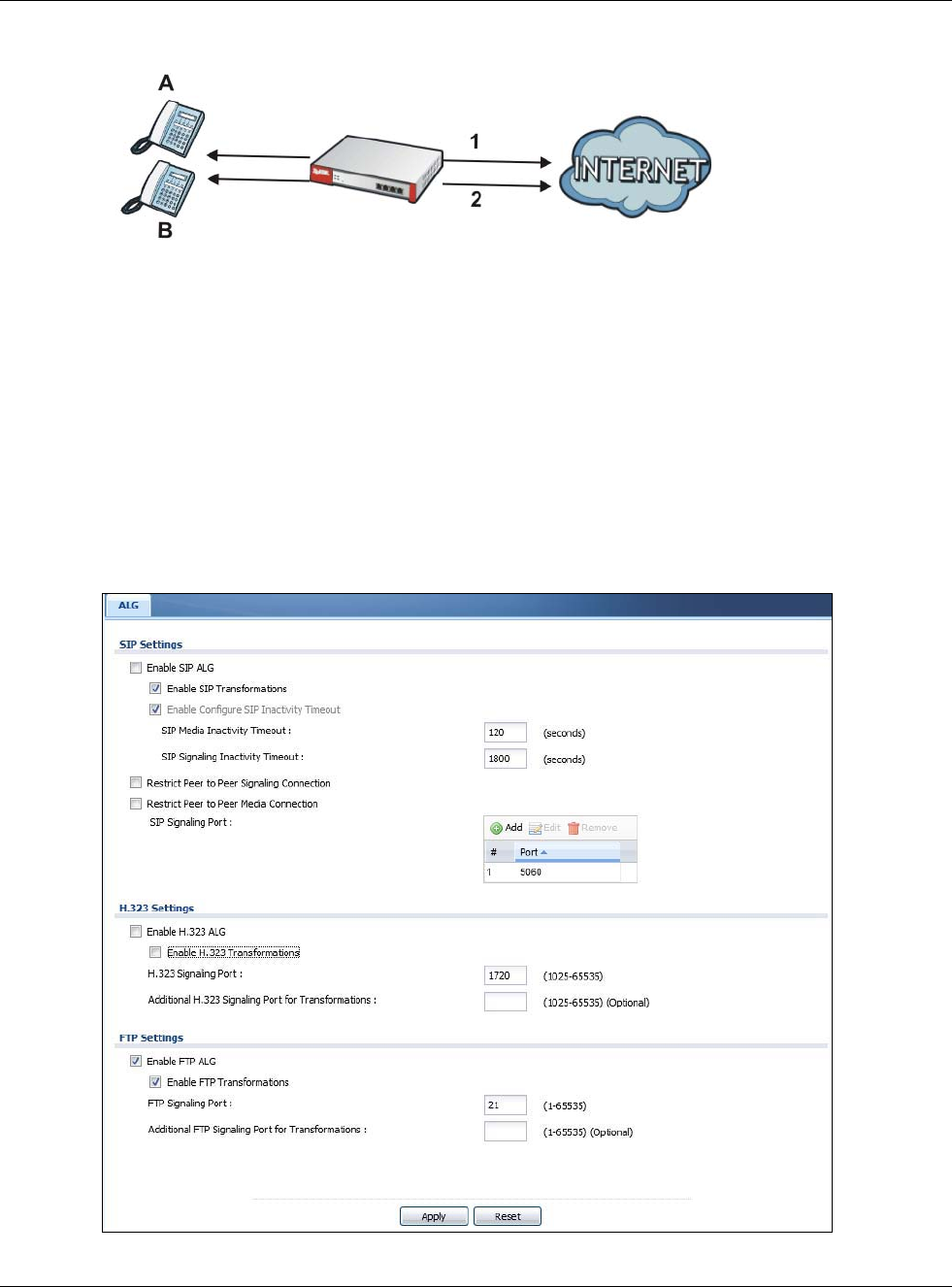
The following example shows SIP signaling (1) and audio (2) sessions between SIP clients A and B
and the SIP server.
Figure 176 SIP ALG Example
The ALG feature is only needed for traffic that goes through the USG’s NAT.
14.1.1 What You Need to Know
Application Layer Gateway (ALG), NAT and Security Policy
The USG can function as an Application Layer Gateway (ALG) to allow certain NAT un-friendly
applications (such as SIP) to operate properly through the USG’s NAT and security policy. The USG
dynamically creates an implicit NAT session and security policy session for the application’s traffic
from the WAN to the LAN. The ALG on the USG supports all of the USG’s NAT mapping types.
FTP ALG
The FTP ALG allows TCP packets with a specified port destination to pass through. If the FTP server
is located on the LAN, you must also configure NAT (port forwarding) and security policies if you
Chapter 14 ALG
USG20(W)-VPN Series User’s Guide
267
want to allow access to the server from the WAN. Bandwidth management can be applied to FTP
ALG traffic.
H.323 ALG
• The H.323 ALG supports peer-to-peer H.323 calls.
• The H.323 ALG handles H.323 calls that go through NAT or that the USG routes. You can also
make other H.323 calls that do not go through NAT or routing. Examples would be calls between
LAN IP addresses that are on the same subnet.
• The H.323 ALG allows calls to go out through NAT. For example, you could make a call from a
private IP address on the LAN to a peer device on the WAN.
• The H.323 ALG operates on TCP packets with a specified port destination.
• Bandwidth management can be applied to H.323 ALG traffic.
• The USG allows H.323 audio connections.
• The USG can also apply bandwidth management to traffic that goes through the H.323 ALG.
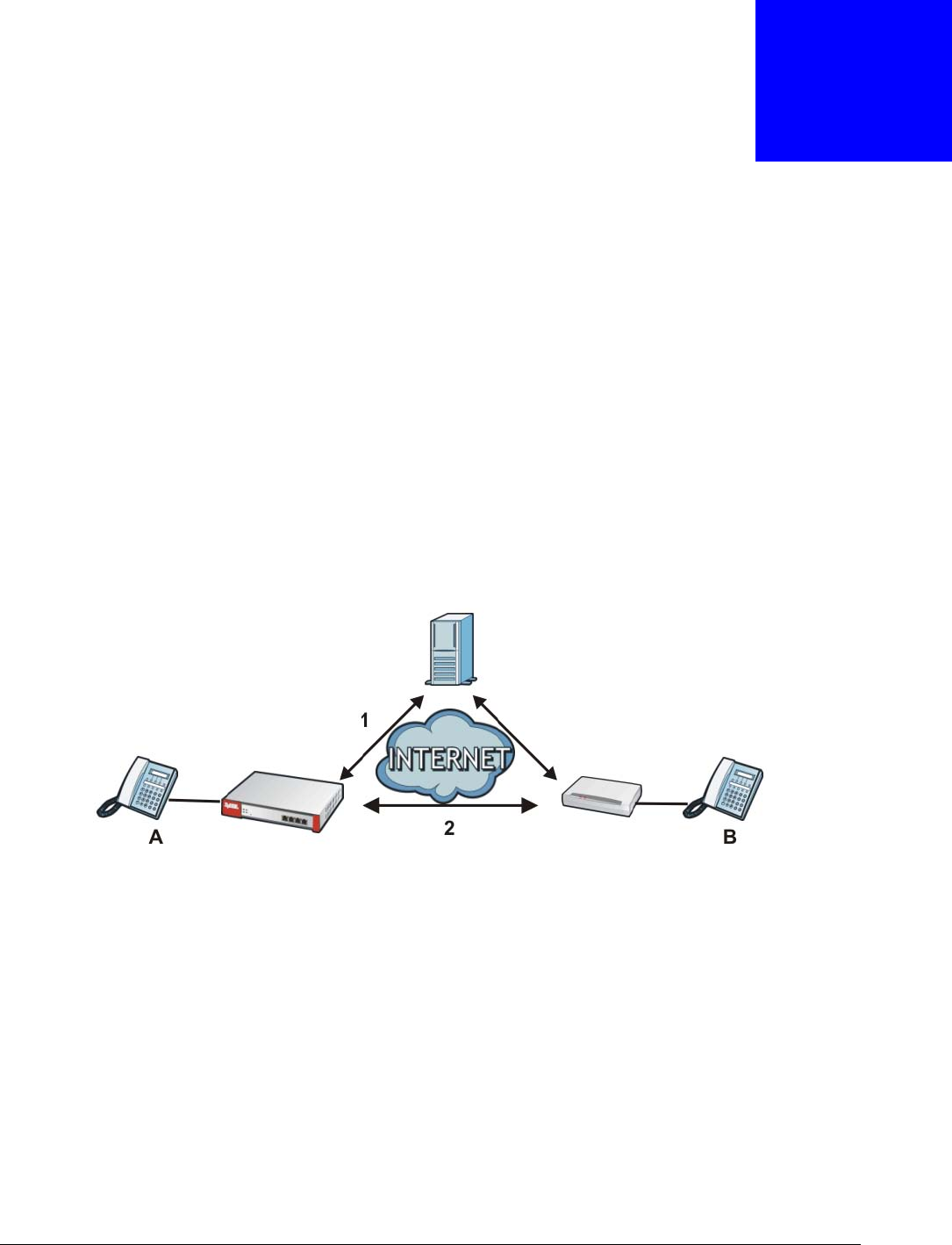
The following example shows H.323 signaling (1) and audio (2) sessions between H.323 devices A
and B.
Figure 177 H.323 ALG Example
SIP ALG
• SIP phones can be in any zone (including LAN, DMZ, WAN), and the SIP server and SIP clients
can be in the same network or different networks. The SIP server cannot be on the LAN. It must
be on the WAN or the DMZ.
• There should be only one SIP server (total) on the USG’s private networks. Any other SIP servers
must be on the WAN. So for example you could have a Back-to-Back User Agent such as the
IPPBX x6004 or an asterisk PBX on the DMZ or on the LAN but not on both.
• Using the SIP ALG allows you to use bandwidth management on SIP traffic. Bandwidth
management can be applied to FTP ALG traffic. Use the option in the Configuration > BWM
screen to configure the highest bandwidth available for SIP traffic.
• The SIP ALG handles SIP calls that go through NAT or that the USG routes. You can also make
other SIP calls that do not go through NAT or routing. Examples would be calls between LAN IP
addresses that are on the same subnet.
• The SIP ALG supports peer-to-peer SIP calls. The security policy (by default) allows peer to peer
calls from the LAN zone to go to the WAN zone and blocks peer to peer calls from the WAN zone
to the LAN zone.
• The SIP ALG allows UDP packets with a specified port destination to pass through.
• The USG allows SIP audio connections.
• You do not need to use TURN (Traversal Using Relay NAT) for VoIP devices behind the USG when
you enable the SIP ALG.
Chapter 14 ALG
USG20(W)-VPN Series User’s Guide
268
Peer-to-Peer Calls and the USG
The USG ALG can allow peer-to-peer VoIP calls for both H.323 and SIP. You must configure the
security policy and NAT (port forwarding) to allow incoming (peer-to-peer) calls from the WAN to a
private IP address on the LAN (or DMZ).
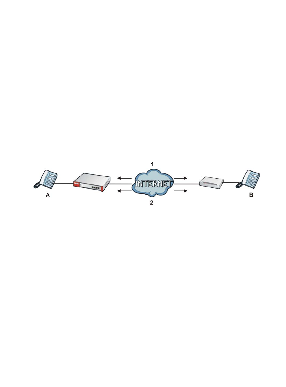
VoIP Calls from the WAN with Multiple Outgoing Calls
When you configure the security policy and NAT (port forwarding) to allow calls from the WAN to a
specific IP address on the LAN, you can also use policy routing to have H.323 (or SIP) calls from
other LAN or DMZ IP addresses go out through a different WAN IP address. The policy routing lets
the USG correctly forward the return traffic for the calls initiated from the LAN IP addresses.
For example, you configure the security policy and NAT to allow LAN IP address A to receive calls
from the Internet through WAN IP address 1. You also use a policy route to have LAN IP address A
make calls out through WAN IP address 1. Configure another policy route to have H.323 (or SIP)
calls from LAN IP addresses B and C go out through WAN IP address 2. Even though only LAN IP
address Acan receive incoming calls from the Internet, LAN IP addresses B and C can still make
calls out to the Internet.
Figure 178 VoIP Calls from the WAN with Multiple Outgoing Calls
VoIP with Multiple WAN IP Addresses
With multiple WAN IP addresses on the USG, you can configure different security policy and NAT
(port forwarding) rules to allow incoming calls from each WAN IP address to go to a specific IP
address on the LAN (or DMZ). Use policy routing to have the H.323 (or SIP) calls from each of those
LAN or DMZ IP addresses go out through the same WAN IP address that calls come in on. The policy
routing lets the USG correctly forward the return traffic for the calls initiated from the LAN IP
addresses.
For example, you configure security policy and NAT rules to allow LAN IP address A to receive calls
through public WAN IP address 1. You configure different security policy and port forwarding rules
to allow LAN IP address B to receive calls through public WAN IP address 2. You configure
corresponding policy routes to have calls from LAN IP address Ago out through WAN IP address 1
and calls from LAN IP address B go out through WAN IP address 2.
Chapter 14 ALG
USG20(W)-VPN Series User’s Guide
269
Figure 179 VoIP with Multiple WAN IP Addresses
14.1.2 Before You Begin
You must also configure the security policy and enable NAT in the USG to allow sessions initiated
from the WAN.
14.2 The ALG Screen
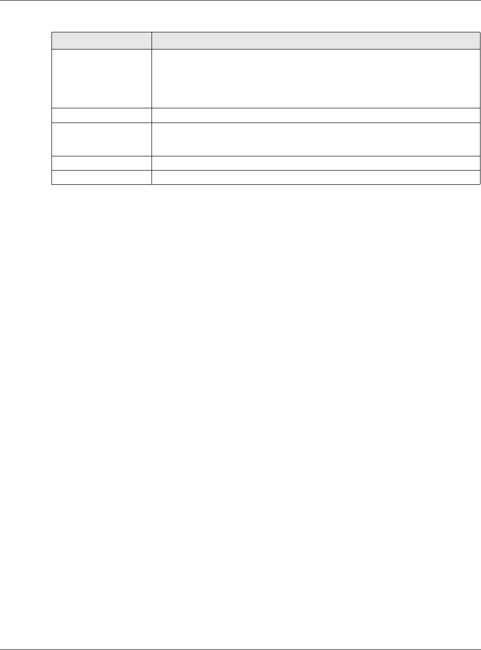
Click Configuration > Network > ALG to open the ALG screen. Use this screen to turn ALGs off
or on, configure the port numbers to which they apply, and configure SIP ALG time outs.
Figure 180 Configuration > Network > ALG

Chapter 14 ALG
USG20(W)-VPN Series User’s Guide
270
The following table describes the labels in this screen.
Table 108 Configuration > Network > ALG
LABEL DESCRIPTION
Enable SIP ALG Turn on the SIP ALG to detect SIP traffic and help build SIP sessions through the
USG’s NAT.
Enable SIP
Transformations
Select this to have the USG modify IP addresses and port numbers embedded in
the SIP data payload.
You do not need to use this if you have a SIP device or server that will modify IP
addresses and port numbers embedded in the SIP data payload.
Enable Configure SIP
Inactivity Timeout
Select this option to have the USG apply SIP media and signaling inactivity time out
limits.
SIP Media Inactivity
Timeout
Use this field to set how many seconds (1~86400) the USG will allow a SIP session
to remain idle (without voice traffic) before dropping it.
If no voice packets go through the SIP ALG before the timeout period expires, the
USG deletes the audio session. You cannot hear anything and you will need to make
a new call to continue your conversation.
SIP Signaling Inactivity
Timeout
Most SIP clients have an “expire” mechanism indicating the lifetime of signaling
sessions. The SIP user agent sends registration packets to the SIP server
periodically and keeps the session alive in the USG.
If the SIP client does not have this mechanism and makes no calls during the USG
SIP timeout, the USG deletes the signaling session after the timeout period. Enter
the SIP signaling session timeout value (1~86400).
Restrict Peer to Peer
Signaling Connection
A signaling connection is used to set up the SIP connection.
Enable this if you want signaling connections to only arrive from the IP address(es)
you registered with. Signaling connections from other IP addresses will be dropped.
Restrict Peer to Peer
Media Connection
A media connection is the audio transfer in a SIP connection.
Enable this if you want media connections to only arrive from the IP address(es)
you registered with. Media connections from other IP addresses will be dropped.
SIP Signaling Port If you are using a custom UDP port number (not 5060) for SIP traffic, enter it here.
Use the Add icon to add fields if you are also using SIP on additional UDP port
numbers.
Additional SIP Signaling
Port (UDP) for
Transformations
If you are also using SIP on an additional UDP port number, enter it here.
Enable H.323 ALG Turn on the H.323 ALG to detect H.323 traffic (used for audio communications) and
help build H.323 sessions through the USG’s NAT.
Enable H.323
Transformations
Select this to have the USG modify IP addresses and port numbers embedded in
the H.323 data payload.
You do not need to use this if you have a H.323 device or server that will modify IP
addresses and port numbers embedded in the H.323 data payload.
H.323 Signaling Port If you are using a custom TCP port number (not 1720) for H.323 traffic, enter it
here.
Additional H.323
Signaling Port for
Transformations
If you are also using H.323 on an additional TCP port number, enter it here.
Enable FTP ALG Turn on the FTP ALG to detect FTP (File Transfer Program) traffic and help build FTP
sessions through the USG’s NAT.
Chapter 14 ALG
USG20(W)-VPN Series User’s Guide
271
14.3 ALG Technical Reference
Here is more detailed information about the Application Layer Gateway.
ALG
Some applications cannot operate through NAT (are NAT un-friendly) because they embed IP
addresses and port numbers in their packets’ data payload. The USG examines and uses IP address
and port number information embedded in the VoIP traffic’s data stream. When a device behind the
USG uses an application for which the USG has VoIP pass through enabled, the USG translates the
device’s private IP address inside the data stream to a public IP address. It also records session
port numbers and allows the related sessions to go through the security policy so the application’s
traffic can come in from the WAN to the LAN.
ALG and Trunks
If you send your ALG-managed traffic through an interface trunk and all of the interfaces are set to
active, you can configure routing policies to specify which interface the ALG-managed traffic uses.
You could also have a trunk with one interface set to active and a second interface set to passive.
The USG does not automatically change ALG-managed connections to the second (passive)
interface when the active interface’s connection goes down. When the active interface’s connection
fails, the client needs to re-initialize the connection through the second interface (that was set to
passive) in order to have the connection go through the second interface. VoIP clients usually re-
register automatically at set intervals or the users can manually force them to re-register.
FTP
File Transfer Protocol (FTP) is an Internet file transfer service that operates on the Internet and over
TCP/IP networks. A system running the FTP server accepts commands from a system running an
FTP client. The service allows users to send commands to the server for uploading and downloading
files.
Enable FTP
Transformations
Select this option to have the USG modify IP addresses and port numbers
embedded in the FTP data payload to match the USG’s NAT environment.
Clear this option if you have an FTP device or server that will modify IP addresses
and port numbers embedded in the FTP data payload to match the USG’s NAT
environment.
FTP Signaling Port If you are using a custom TCP port number (not 21) for FTP traffic, enter it here.
Additional FTP Signaling
Port for
Transformations
If you are also using FTP on an additional TCP port number, enter it here.
Apply Click Apply to save your changes back to the USG.
Reset Click Reset to return the screen to its last-saved settings.
Table 108 Configuration > Network > ALG (continued)
LABEL DESCRIPTION

Chapter 14 ALG
USG20(W)-VPN Series User’s Guide
272
H.323
H.323 is a standard teleconferencing protocol suite that provides audio, data and video
conferencing. It allows for real-time point-to-point and multipoint communication between client
computers over a packet-based network that does not provide a guaranteed quality of service.
NetMeeting uses H.323.
SIP
The Session Initiation Protocol (SIP) is an application-layer control (signaling) protocol that handles
the setting up, altering and tearing down of voice and multimedia sessions over the Internet. SIP is
used in VoIP (Voice over IP), the sending of voice signals over the Internet Protocol.
SIP signaling is separate from the media for which it handles sessions. The media that is exchanged
during the session can use a different path from that of the signaling. SIP handles telephone calls
and can interface with traditional circuit-switched telephone networks.
RTP
When you make a VoIP call using H.323 or SIP, the RTP (Real time Transport Protocol) is used to
handle voice data transfer. See RFC 1889 for details on RTP.

USG20(W)-VPN Series User’s Guide
273
CHAPTER 15
UPnP
15.1 UPnP and NAT-PMP Overview
The USG supports both UPnP and NAT-PMP to permit networking devices to discover each other and
connect seamlessly.
Universal Plug and Play (UPnP) is a distributed, open networking standard that uses TCP/IP for
simple peer-to-peer network connectivity between devices. A UPnP device can dynamically join a
network, obtain an IP address, convey its capabilities and learn about other devices on the network.
In turn, a device can leave a network smoothly and automatically when it is no longer in use. A
gateway that supports UPnP is called Internet Gateway Device (IGD). The standardized Device
Control Protocol (DCP) is defined by the UPnP Forum for IGDs to configure port mapping
automatically.
NAT Port Mapping Protocol (NAT-PMP), introduced by Apple and implemented in current Apple
products, is used as an alternative NAT traversal solution to the UPnP IGD protocol. NAT-PMP runs
over UDP port 5351. NAT-PMP is much simpler than UPnP IGD and mainly designed for small home
networks. It allows a client behind a NAT router to retrieve the router’s public IP address and port
number and make them known to the peer device with which it wants to communicate. The client
can automatically configure the NAT router to create a port mapping to allow the peer to contact it.
15.2 What You Need to Know
UPnP hardware is identified as an icon in the Network Connections folder (Windows XP). Each UPnP
compatible device installed on your network will appear as a separate icon. Selecting the icon of a
UPnP device will allow you to access the information and properties of that device.
15.2.1 NAT Traversal
UPnP NAT traversal automates the process of allowing an application to operate through NAT. UPnP
network devices can automatically configure network addressing, announce their presence in the
network to other UPnP devices and enable exchange of simple product and service descriptions.
NAT traversal allows the following:
• Dynamic port mapping
• Learning public IP addresses
• Assigning lease times to mappings
Windows Messenger is an example of an application that supports NAT traversal and UPnP.
See the NAT chapter for more information on NAT.
Chapter 15 UPnP
USG20(W)-VPN Series User’s Guide
274
15.2.2 Cautions with UPnP and NAT-PMP
The automated nature of NAT traversal applications in establishing their own services and opening
security policy ports may present network security issues. Network information and configuration
may also be obtained and modified by users in some network environments.
When a UPnP or NAT-PMP device joins a network, it announces its presence with a multicast
message. For security reasons, the USG allows multicast messages on the LAN only.
All UPnP-enabled or NAT-PMP-enabled devices may communicate freely with each other without
additional configuration. Disable UPnP or NAT-PMP if this is not your intention.
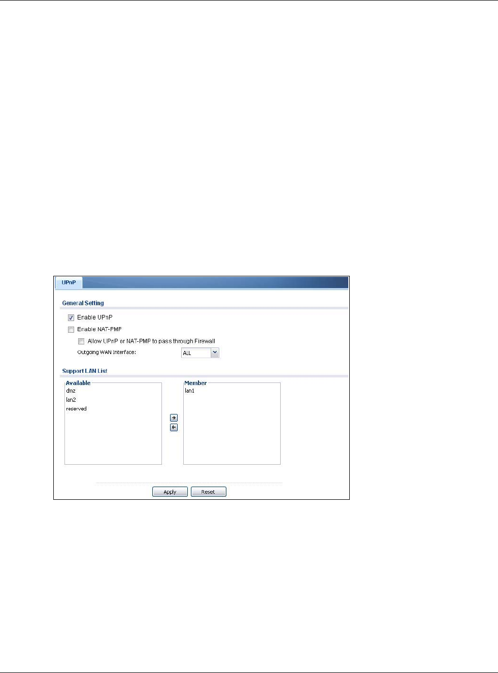
15.3 UPnP Screen
Use this screen to enable UPnP and NAT-PMP on your USG.
Click Configuration > Network > UPnP to display the screen shown next.
Figure 181 Configuration > Network > UPnP
Chapter 15 UPnP
USG20(W)-VPN Series User’s Guide
275
The following table describes the fields in this screen.
15.4 Technical Reference
The sections show examples of using UPnP.
15.4.1 Turning on UPnP in Windows 7 Example
This section shows you how to use the UPnP feature in Windows 7. UPnP server is installed in
Windows 7. Activate UPnP on the USG.
Make sure the computer is connected to a LAN port of the USG. Turn on your computer and the
USG.
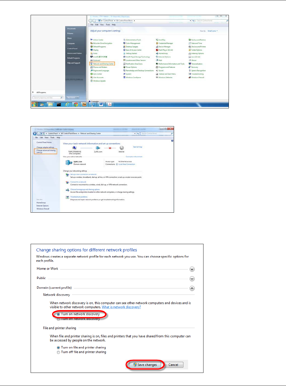
1Click the start icon, Control Panel and then the Network and Sharing Center.
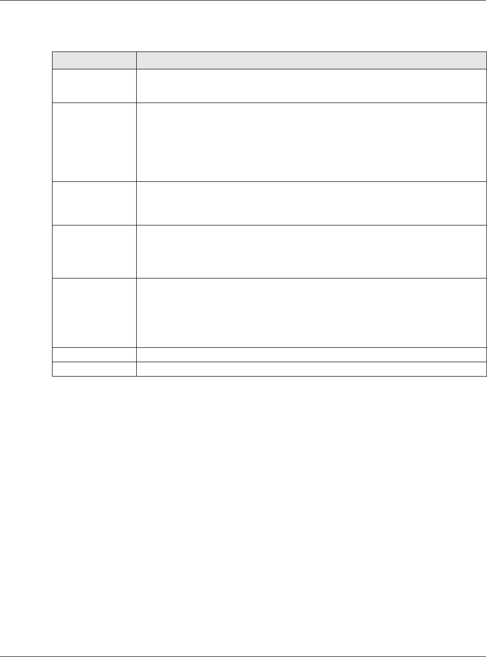
Table 109 Configuration > Network > UPnP
LABEL DESCRIPTION
Enable UPnP Select this check box to activate UPnP on the USG. Be aware that anyone could use a
UPnP application to open the web configurator's login screen without entering the USG's
IP address (although you must still enter the password to access the web configurator).
Enable NAT-PMP NAT Port Mapping Protocol (NAT-PMP) automates port forwarding to allow a computer in
a private network (behind the USG) to automatically configure the USG to allow
computers outside the private network to contact it.
Select this check box to activate NAT-PMP on the USG. Be aware that anyone could use
a NAT-PMP application to open the web configurator's login screen without entering the
USG's IP address (although you must still enter the password to access the web
configurator).
Allow UPnP or
NAT-PMP to
pass through
Firewall
Select this check box to allow traffic from UPnP-enabled or NAT-PMP-enabled
applications to bypass the security policy.
Clear this check box to have the security policy block all UPnP or NAT-PMP application
packets (for example, MSN packets).
Outgoing WAN
Interface Select through which WAN interface(s) you want to send out traffic from UPnP-enabled
or NAT-PMP-enabled applications. If the WAN interface you select loses its connection,
the USG attempts to use the other WAN interface. If the other WAN interface also does
not work, the USG drops outgoing packets from UPnP-enabled or NAT-PMP-enabled
applications.
Support LAN List The Available list displays the name(s) of the internal interface(s) on which the USG
supports UPnP and/or NAT-PMP.
To enable UPnP and/or NAT-PMP on an interface, you can double-click a single entry to
move it or use the [Shift] or [Ctrl] key to select multiple entriess and click the right
arrow button to add to the Member list. To remove an interface, select the name(s) in
the Member list and click the left arrow button.
Apply Click Apply to save your changes back to the USG.
Reset Click Reset to return the screen to its last-saved settings.
Chapter 15 UPnP
USG20(W)-VPN Series User’s Guide
276
2Click Change Advanced Sharing Settings.
3Select Turn on network discovery and click Save Changes. Network discovery allows your
computer to find other computers and devices on the network and other computers on the network
to find your computer. This makes it easier to share files and printers.
Chapter 15 UPnP
USG20(W)-VPN Series User’s Guide
277
15.4.2 Using UPnP in Windows XP Example
This section shows you how to use the UPnP feature in Windows XP. You must already have UPnP
installed in Windows XP and UPnP activated on the USG.
Make sure the computer is connected to a LAN port of the USG. Turn on your computer and the
USG.
15.4.2.1 Auto-discover Your UPnP-enabled Network Device
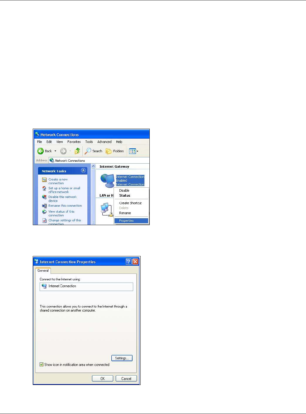
1Click start and Control Panel. Double-click Network Connections. An icon displays under
Internet Gateway.
2Right-click the icon and select Properties.
Figure 182 Network Connections
3In the Internet Connection Properties window, click Settings to see the port mappings there
were automatically created.
Figure 183 Internet Connection Properties
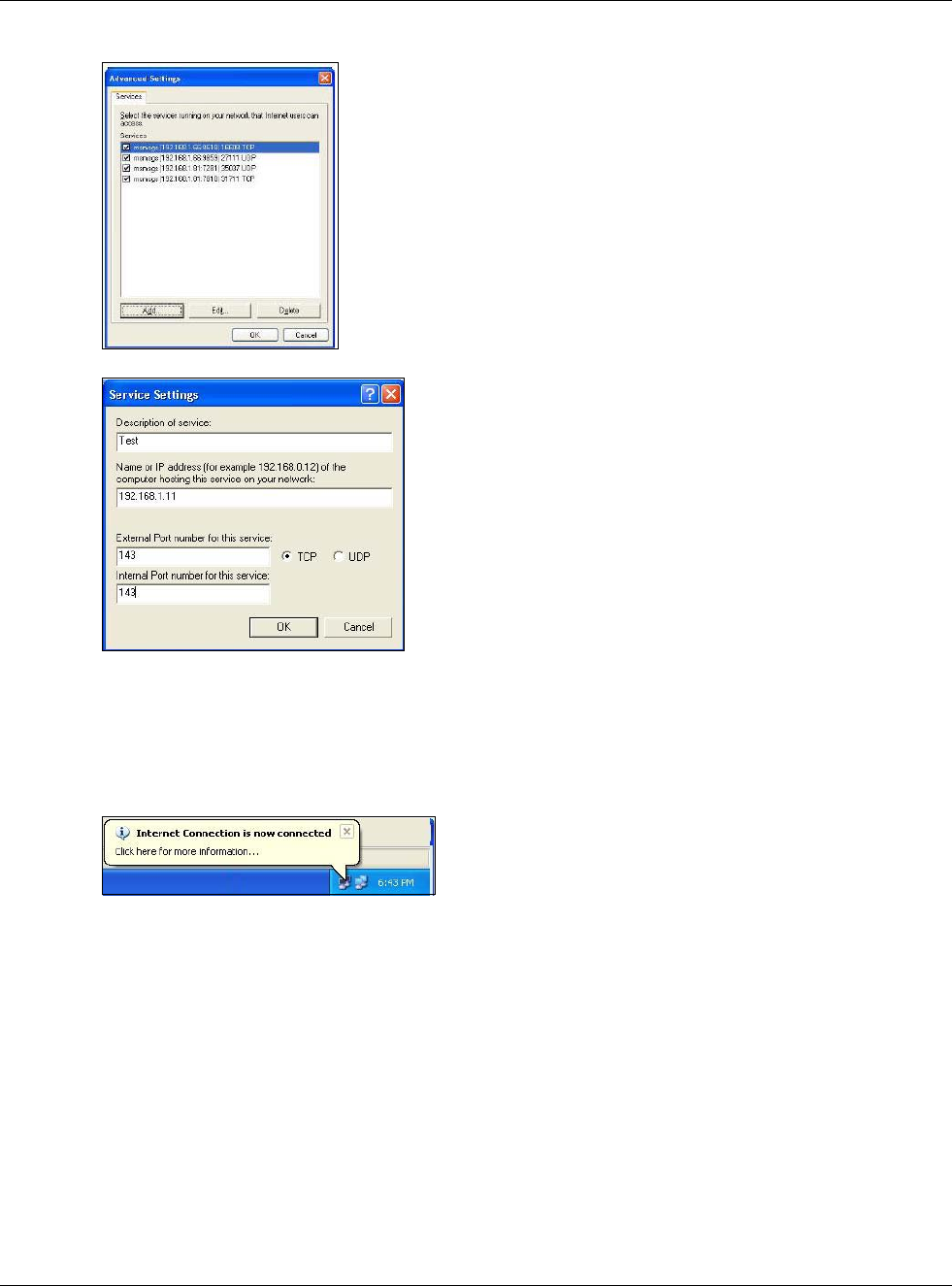
4You may edit or delete the port mappings or click Add to manually add port mappings.
Chapter 15 UPnP
USG20(W)-VPN Series User’s Guide
278
Figure 184 Internet Connection Properties: Advanced Settings
Figure 185 Internet Connection Properties: Advanced Settings: Add
Note: When the UPnP-enabled device is disconnected from your computer, all port
mappings will be deleted automatically.
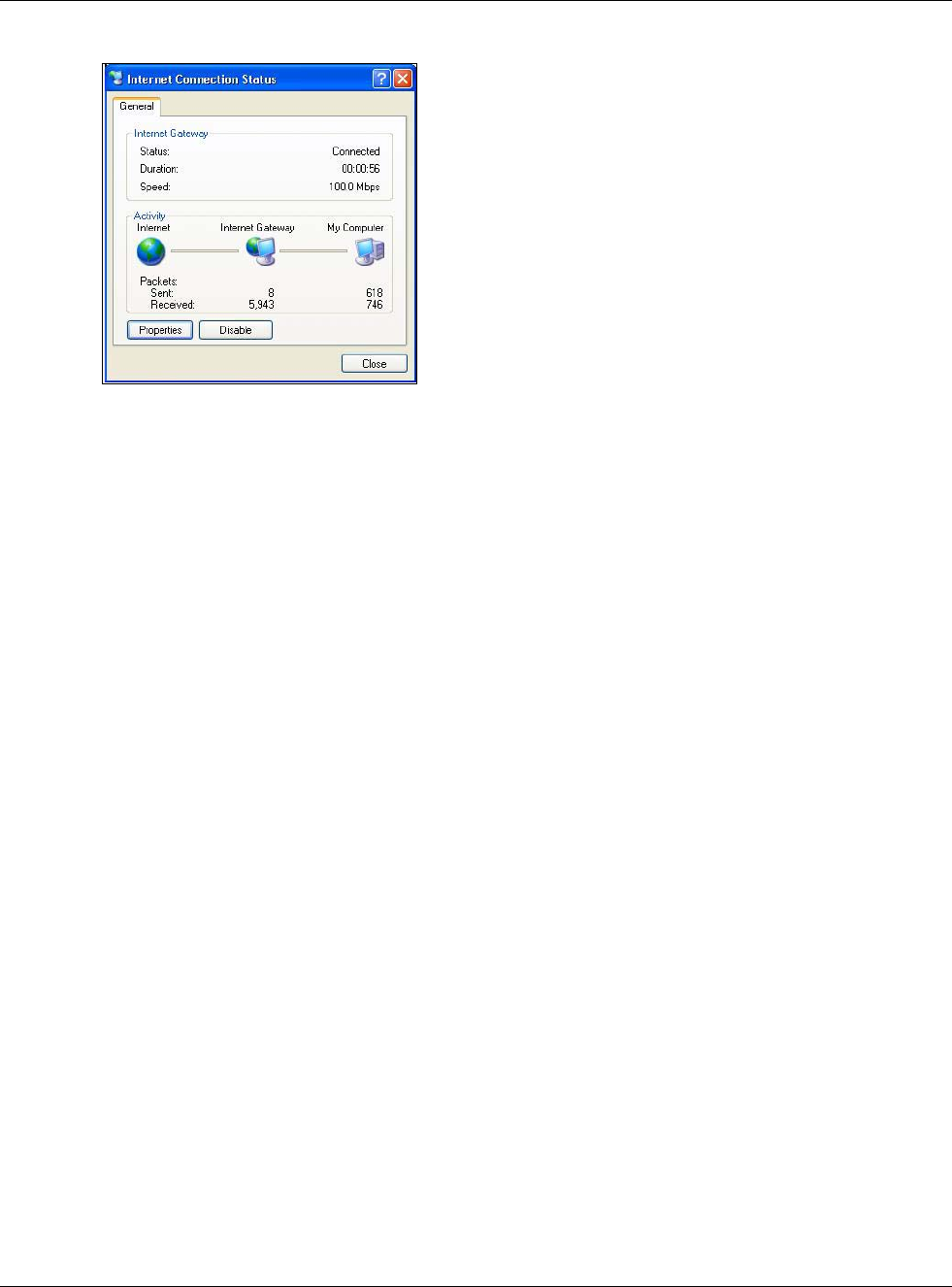
5Select Show icon in notification area when connected option and click OK. An icon displays in
the system tray.
Figure 186 System Tray Icon
6Double-click on the icon to display your current Internet connection status.
Chapter 15 UPnP
USG20(W)-VPN Series User’s Guide
279
Figure 187 Internet Connection Status
15.4.3 Web Configurator Easy Access
With UPnP, you can access the web-based configurator on the USG without finding out the IP
address of the USG first. This comes helpful if you do not know the IP address of the USG.
Follow the steps below to access the web configurator.
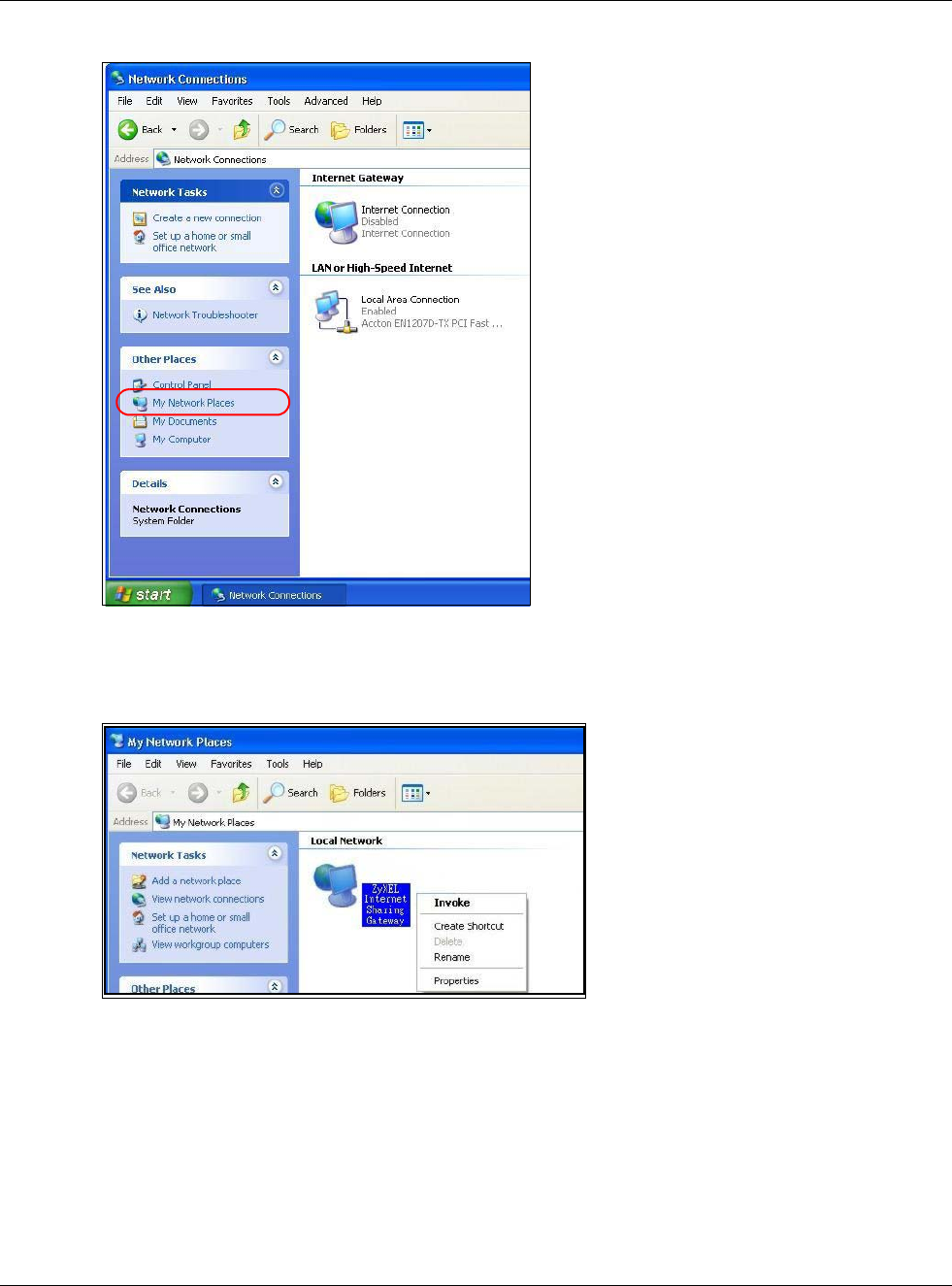
1Click Start and then Control Panel.
2Double-click Network Connections.
3Select My Network Places under Other Places.
Chapter 15 UPnP
USG20(W)-VPN Series User’s Guide
280
Figure 188 Network Connections
4An icon with the description for each UPnP-enabled device displays under Local Network.
5Right-click on the icon for your USG and select Invoke. The web configurator login screen displays.
Figure 189 Network Connections: My Network Places
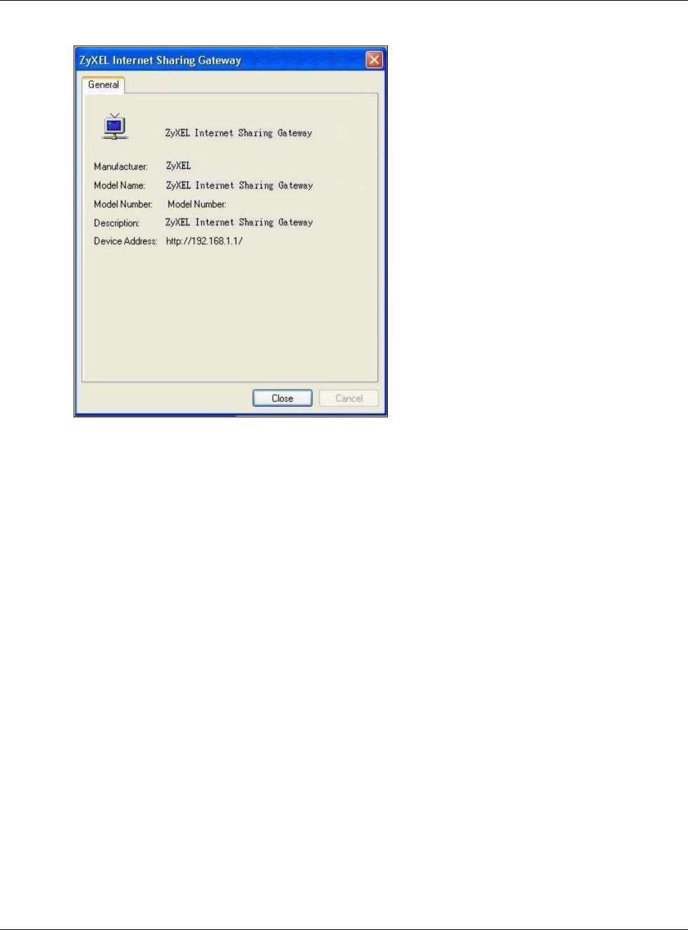
6Right-click on the icon for your USG and select Properties. A properties window displays with basic
information about the USG.
Chapter 15 UPnP
USG20(W)-VPN Series User’s Guide
281
Figure 190 Network Connections: My Network Places: Properties: Example
USG20(W)-VPN Series User’s Guide
282
CHAPTER 16
IP/MAC Binding
16.1 IP/MAC Binding Overview
IP address to MAC address binding helps ensure that only the intended devices get to use privileged
IP addresses. The USG uses DHCP to assign IP addresses and records the MAC address it assigned
to each IP address. The USG then checks incoming connection attempts against this list. A user
cannot manually assign another IP to his computer and use it to connect to the USG.
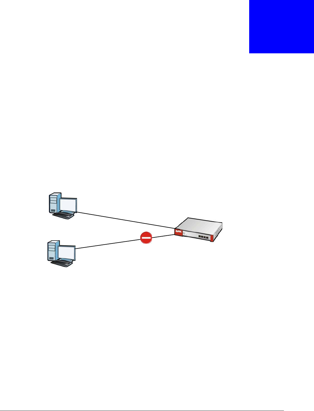
Suppose you configure access privileges for IP address 192.168.1.27 and use static DHCP to assign
it to Tim’s computer’s MAC address of 12:34:56:78:90:AB. IP/MAC binding drops traffic from any
computer trying to use IP address 192.168.1.27 with another MAC address.
Figure 191 IP/MAC Binding Example
16.1.1 What You Can Do in this Chapter
•Use the Summary and Edit screens (Section 16.2 on page 283) to bind IP addresses to MAC
addresses.
•Use the Exempt List screen (Section 16.3 on page 285) to configure ranges of IP addresses to
which the USG does not apply IP/MAC binding.
16.1.2 What You Need to Know
DHCP
IP/MAC address bindings are based on the USG’s dynamic and static DHCP entries.
MAC: 12:34:56:78:90:AB
Tim IP: 192.168.1.27
MAC: AB:CD:EF:12:34:56
Jim
IP: 192.168.1.27
Chapter 16 IP/MAC Binding
USG20(W)-VPN Series User’s Guide
283
Interfaces Used With IP/MAC Binding
IP/MAC address bindings are grouped by interface. You can use IP/MAC binding with Ethernet,
bridge, VLAN, and WLAN interfaces. You can also enable or disable IP/MAC binding and logging in
an interface’s configuration screen.
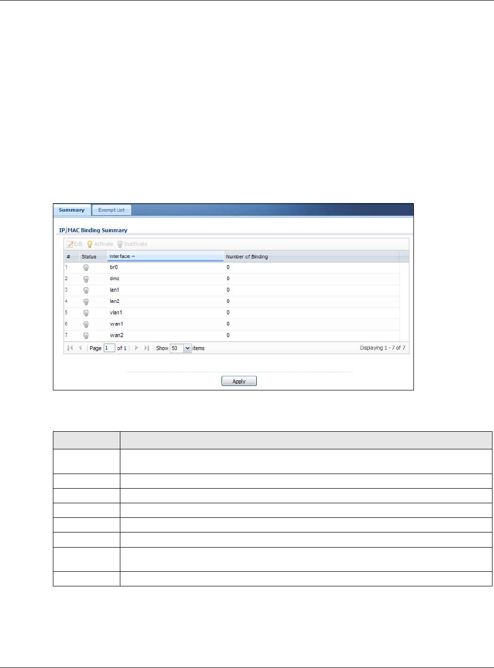
16.2 IP/MAC Binding Summary
Click Configuration > Network > IP/MAC Binding to open the IP/MAC Binding Summary
screen. This screen lists the total number of IP to MAC address bindings for devices connected to
each supported interface.
Figure 192 Configuration > Network > IP/MAC Binding > Summary
The following table describes the labels in this screen.
16.2.1 IP/MAC Binding Edit
Click Configuration > Network > IP/MAC Binding > Edit to open the IP/MAC Binding Edit
screen. Use this screen to configure an interface’s IP to MAC address binding settings.
Table 110 Configuration > Network > IP/MAC Binding > Summary
LABEL DESCRIPTION
Edit Double-click an entry or select it and click Edit to open a screen where you can modify the
entry’s settings.
Activate To turn on an entry, select it and click Activate.
Inactivate To turn off an entry, select it and click Inactivate.
# This field is a sequential value, and it is not associated with a specific entry.
Status This icon is lit when the entry is active and dimmed when the entry is inactive.
Interface This is the name of an interface that supports IP/MAC binding.
Number of
Binding
This field displays the interface’s total number of IP/MAC bindings and IP addresses that the
interface has assigned by DHCP.
Apply Click Apply to save your changes back to the USG.
Chapter 16 IP/MAC Binding
USG20(W)-VPN Series User’s Guide
284
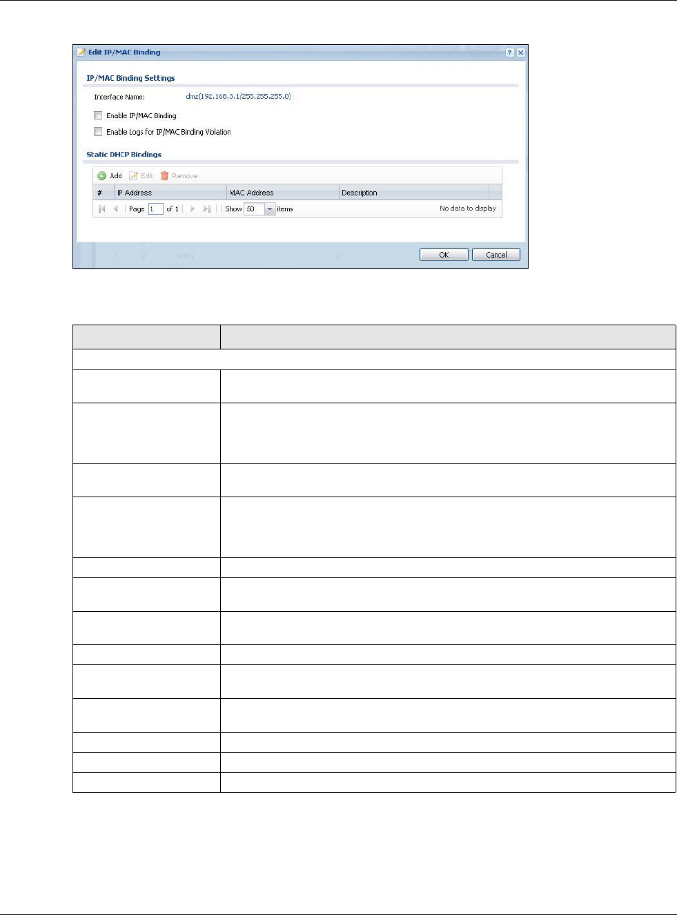
Figure 193 Configuration > Network > IP/MAC Binding > Edit
The following table describes the labels in this screen.
16.2.2 Static DHCP Edit
Click Configuration > Network > IP/MAC Binding > Edit to open the IP/MAC Binding Edit
screen. Click the Add or Edit icon to open the following screen. Use this screen to configure an
interface’s IP to MAC address binding settings.
Table 111 Configuration > Network > IP/MAC Binding > Edit
LABEL DESCRIPTION
IP/MAC Binding Settings
Interface Name This field displays the name of the interface within the USG and the interface’s IP
address and subnet mask.
Enable IP/MAC
Binding Select this option to have this interface enforce links between specific IP
addresses and specific MAC addresses. This stops anyone else from manually
using a bound IP address on another device connected to this interface. Use this
to make use only the intended users get to use specific IP addresses.
Enable Logs for IP/
MAC Binding Violation Select this option to have the USG generate a log if a device connected to this
interface attempts to use an IP address not assigned by the USG.
Static DHCP Bindings This table lists the bound IP and MAC addresses. The USG checks this table when
it assigns IP addresses. If the computer’s MAC address is in the table, the USG
assigns the corresponding IP address. You can also access this table from the
interface’s edit screen.
Add Click this to create a new entry.
Edit Double-click an entry or select it and click Edit to open a screen where you can
modify the entry’s settings.
Remove To remove an entry, select it and click Remove. The USG confirms you want to
remove it before doing so.
#This is the index number of the static DHCP entry.
IP Address This is the IP address that the USG assigns to a device with the entry’s MAC
address.
MAC Address This is the MAC address of the device to which the USG assigns the entry’s IP
address.
Description This helps identify the entry.
OK Click OK to save your changes back to the USG.
Cancel Click Cancel to exit this screen without saving.
Chapter 16 IP/MAC Binding
USG20(W)-VPN Series User’s Guide
285
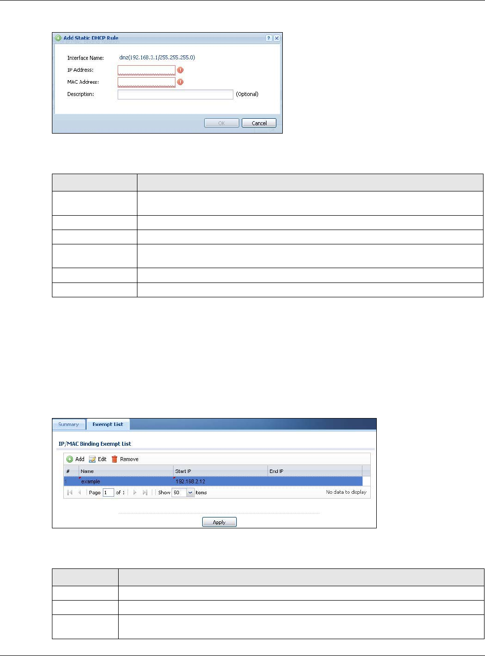
Figure 194 Configuration > Network > IP/MAC Binding > Edit > Add
The following table describes the labels in this screen.
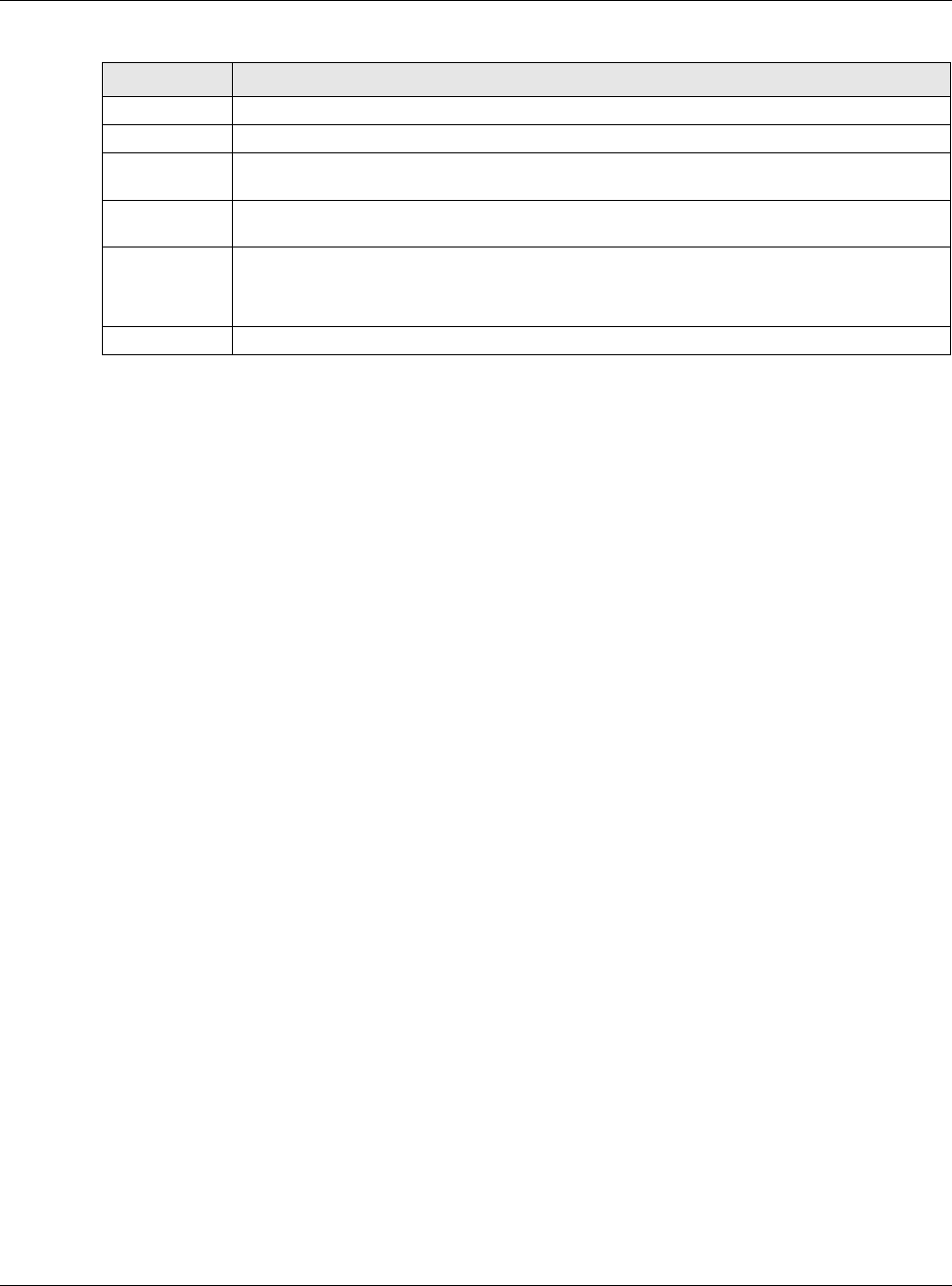
16.3 IP/MAC Binding Exempt List
Click Configuration > Network > IP/MAC Binding > Exempt List to open the IP/MAC
Binding Exempt List screen. Use this screen to configure ranges of IP addresses to which the USG
does not apply IP/MAC binding.
Figure 195 Configuration > Network > IP/MAC Binding > Exempt List
The following table describes the labels in this screen.
Table 112 Configuration > Network > IP/MAC Binding > Edit > Add
LABEL DESCRIPTION
Interface Name This field displays the name of the interface within the USG and the interface’s IP
address and subnet mask.
IP Address Enter the IP address that the USG is to assign to a device with the entry’s MAC address.
MAC Address Enter the MAC address of the device to which the USG assigns the entry’s IP address.
Description Enter up to 64 printable ASCII characters to help identify the entry. For example, you
may want to list the computer’s owner.
OK Click OK to save your changes back to the USG.
Cancel Click Cancel to exit this screen without saving.
Table 113 Configuration > Network > IP/MAC Binding > Exempt List
LABEL DESCRIPTION
Add Click this to create a new entry.
Edit Click an entry or select it and click Edit to modify the entry’s settings.
Remove To remove an entry, select it and click Remove. The USG confirms you want to remove it
before doing so.
Chapter 16 IP/MAC Binding
USG20(W)-VPN Series User’s Guide
286
#This is the index number of the IP/MAC binding list entry.
Name Enter a name to help identify this entry.
Start IP Enter the first IP address in a range of IP addresses for which the USG does not apply IP/
MAC binding.
End IP Enter the last IP address in a range of IP addresses for which the USG does not apply IP/MAC
binding.
Add icon Click the Add icon to add a new entry.
Click the Remove icon to delete an entry. A window displays asking you to confirm that you
want to delete it.
Apply Click Apply to save your changes back to the USG.
Table 113 Configuration > Network > IP/MAC Binding > Exempt List (continued)
LABEL DESCRIPTION
USG20(W)-VPN Series User’s Guide
287
CHAPTER 17
Layer 2 Isolation
17.1 Overview
Layer-2 isolation is used to prevent connected devices from communicating with each other in the
USG’s local network(s), except for the devices in the white list, when layer-2 isolation is enabled on
the USG and the local interface(s).
Note: The security policy control must be enabled before you can use layer-2 isolation.
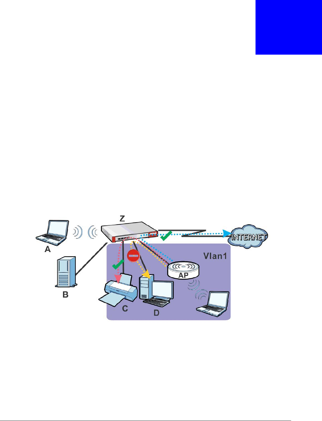
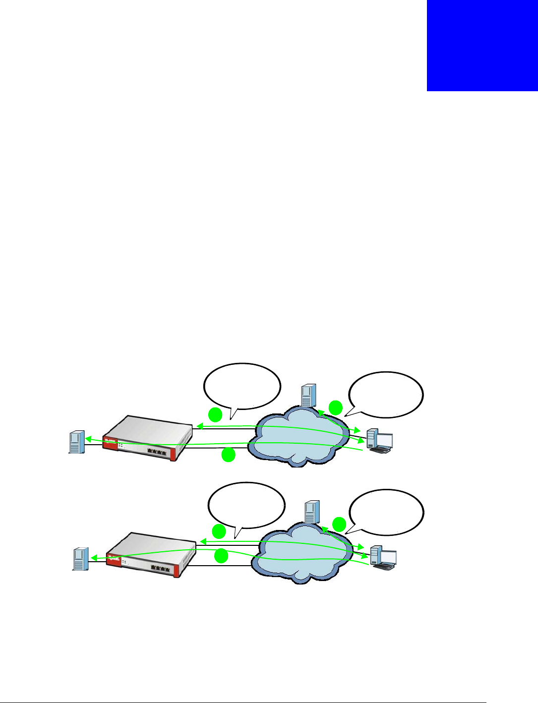
In the following example, layer-2 isolation is enabled on the USG’s interface Vlan1. A printer, PC
and AP are in the Vlan1. The IP address of network printer (C) is added to the white list. With this
setting, the connected AP then cannot communicate with the PC (D), but can access the network
printer (C), server (B), wireless client (A) and the Internet.
Figure 196 Layer-2 Isolation Application
17.1.1 What You Can Do in this Chapter
•Use the General screen (Section 17.2 on page 288) to enable layer-2 isolation on the USG and
the internal interface(s).
•Use the White List screen (Section 17.3 on page 288) to enable and configures the white list.
Chapter 17 Layer 2 Isolation
USG20(W)-VPN Series User’s Guide
288
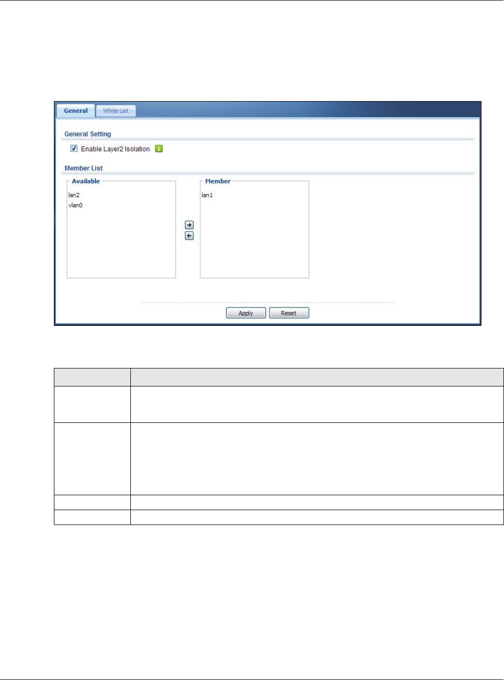
17.2 Layer-2 Isolation General Screen
This screen allows you to enable Layer-2 isolation on the USG and specific internal interface(s). To
access this screen click Configuration > Network > Layer 2 Isolation.
Figure 197 Configuration > Network > Layer 2 Isolation
The following table describes the labels in this screen.
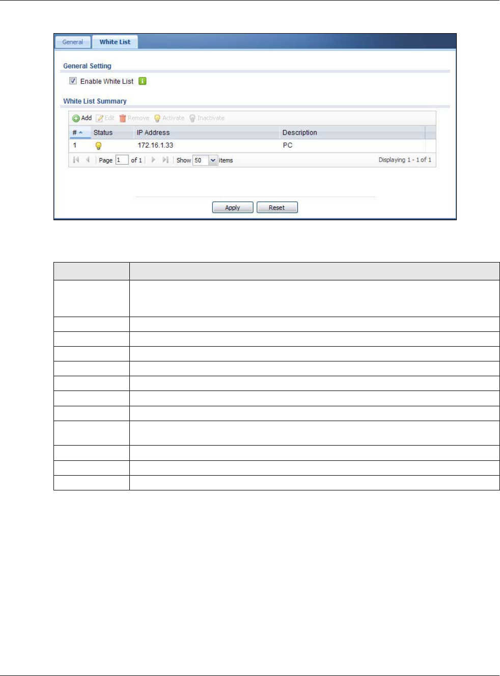
17.3 White List Screen
IP addresses that are not listed in the white list are blocked from communicating with other devices
in the layer-2-isolation-enabled internal interface(s) except for broadcast packets.
To access this screen click Configuration > Network > Layer 2 Isolation > White List.
Table 114 Configuration > Network > Layer 2 Isolation
LABEL DESCRIPTION
Enable Layer2
Isolation
Select this option to turn on the layer-2 isolation feature on the USG.
Note: You can enable this feature only when the security policy is enabled.
Member List The Available list displays the name(s) of the internal interface(s) on which you can
enable layer-2 isolation.
To enable layer-2 isolation on an interface, you can double-click a single entry to move it
or use the [Shift] or [Ctrl] key to select multiple entriess and click the right arrow button to
add to the Member list. To remove an interface, select the name(s) in the Member list
and click the left arrow button.
Apply Click Apply to save your changes back to the USG.
Reset Click Reset to return the screen to its last-saved settings.
Chapter 17 Layer 2 Isolation
USG20(W)-VPN Series User’s Guide
289
Figure 198 Configuration > Network > Layer 2 Isolation > White List
The following table describes the labels in this screen.
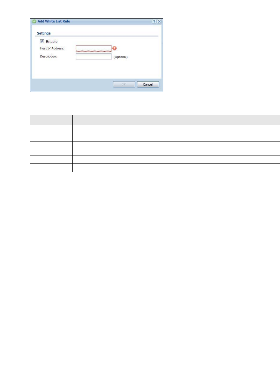
17.3.1 Add/Edit White List Rule
This screen allows you to create a new rule in the white list or edit an existing one. To access this
screen, click the Add button or select an entry from the list and click the Edit button.
Note: You can configure up to 100 white list rules on the USG.
Note: You need to know the IP address of each connected device that you want to allow
to be accessed by other devices when layer-2 isolation is enabled.
Table 115 Configuration > Network > Layer 2 Isolation > White List
LABEL DESCRIPTION
Enable White List Select this option to turn on the white list on the USG.
Note: You can enable this feature only when the security policy is enabled.
Add Click this to add a new rule.
Edit Click this to edit the selected rule.
Remove Click this to remove the selected rule.
Activate To turn on an entry, select it and click Activate.
Inactivate To turn off an entry, select it and click Inactivate.
# This field is a sequential value, and it is not associated with a specific rule.
Status This icon is lit when the rule is active and dimmed when the rule is inactive.
IP Address This field displays the IP address of device that can be accessed by the devices connected
to an internal interface on which layer-2 isolation is enabled.
Description This field displays the description for the IP address in this rule.
Apply Click Apply to save your changes back to the USG.
Reset Click Reset to return the screen to its last-saved settings.
Chapter 17 Layer 2 Isolation
USG20(W)-VPN Series User’s Guide
290
Figure 199 Configuration > Network > Layer 2 Isolation > White List > Add/Edit
The following table describes the labels in this screen.
Table 116 Configuration > Network > Layer 2 Isolation > White List > Add/Edit
LABEL DESCRIPTION
Enable Select this option to turn on the rule.
Host IP Address Enter an IPv4 address associated with this rule.
Description Specify a description for the IP address associated with this rule. Enter up to 60 characters,
spaces and underscores allowed.
OK Click OK to save your changes back to the USG.
Cancel Click Cancel to exit this screen without saving your changes.
USG20(W)-VPN Series User’s Guide
291
CHAPTER 18
Inbound Load Balancing
18.1 Inbound Load Balancing Overview
Inbound load balancing enables the USG to respond to a DNS query message!with a different IP
address for DNS name resolution. The USG checks which member interface has the least load and
responds to the DNS query message with the interface’s IP address.
In the following figure, an Internet host (A) sends a DNS query message to the DNS server (D) in
order to resolve a domain name of www.example.com. DNS server D redirects it to the USG (Z)’s
WAN1 with an IP address of 1.1.1.1. The USG receives the DNS query message and responds to it
with the WAN2’s IP address, 2.2.2.2, because the WAN2 has the least load at that moment.
Another Internet host (B) also sends a DNS query message to ask where www.example.com is. The
USG responds to it with the WAN1’s IP address, 1.1.1.1, since WAN1 has the least load this time.
Figure 200 DNS Load Balancing Example
18.1.1 What You Can Do in this Chapter
•Use the Inbound LB screen (see Section 18.2 on page 292) to view a list of the configured DNS
load balancing rules.
•Use the Inbound LB Add/Edit screen (see Section 18.2.1 on page 293) to add or edit a DNS
load balancing rule.
Internet
Where is
www.example.com?
Ask 1.1.1.1.
A:
D:
A
D
1.1.1.1
2.2.2.2
W
Z
Where is
www.example.com?
It’s 2.2.2.2.
A:
Z:
1
2
3
Internet
B
D
1.1.1.1
2.2.2.2
W
Z
1
2
3
Where is
www.example.com?
Ask 1.1.1.1.
B:
D:
Where is
www.example.com?
It’s 1.1.1.1
B:
Z:
Chapter 18 Inbound Load Balancing
USG20(W)-VPN Series User’s Guide
292
18.2 The Inbound LB Screen
The Inbound LB screen provides a summary of all DNS load balancing rules and the details. You
can also use this screen to add, edit, or remove the rules. Click Configuration > Network >
Inbound LB to open the following screen.
Note: After you finish the inbound load balancing settings, go to security policy and NAT
screens to configure the corresponding rule and virtual server to allow the Internet
users to access your internal servers.
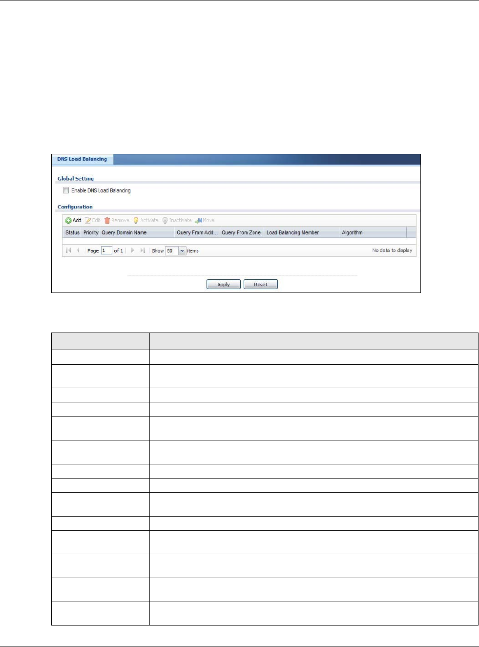
Figure 201 Configuration > Network > DNS Inbound LB
The following table describes the labels in this screen.
Table 117 Configuration > Network > Inbound LB
LABEL DESCRIPTION
Global Setting
Enable DNS Load
Balancing
Select this to enable DNS load balancing.
Configuration
Add Click this to create a new entry.
Edit Double-click an entry or select it and click Edit to open a screen where you can
modify the entry’s settings.
Remove To remove an entry, select it and click Remove. The USG confirms you want to
remove it before doing so.
Activate To turn on an entry, select it and click Activate.
Inactivate To turn off an entry, select it and click Inactivate.
Move To move an entry to a different number in the list, click the Move icon. In the field
that appears, specify the number to which you want to move the entry.
Status This icon is lit when the entry is active and dimmed when the entry is inactive.
Priority This field displays the order in which the USG checks the member interfaces of this
DNS load balancing rule.
Query Domain Name This field displays the domain name for which the USG manages load balancing
between the specified interfaces.
Query From Address This field displays the source IP address of the DNS query messages to which the
USG applies the DNS load balancing rule.
Query From Zone The USG applies the DNS load balancing rule to the query messages received from
this zone.
Chapter 18 Inbound Load Balancing
USG20(W)-VPN Series User’s Guide
293
18.2.1 The Inbound LB Add/Edit Screen
The Add DNS Load Balancing screen allows you to add a domain name for which the USG
manages load balancing between the specified interfaces. You can configure the USG to apply DNS
load balancing to some specific hosts only by configuring the Query From settings. Click
Configuration > Network > Inbound LB and then the Add or Edit icon to open this screen.
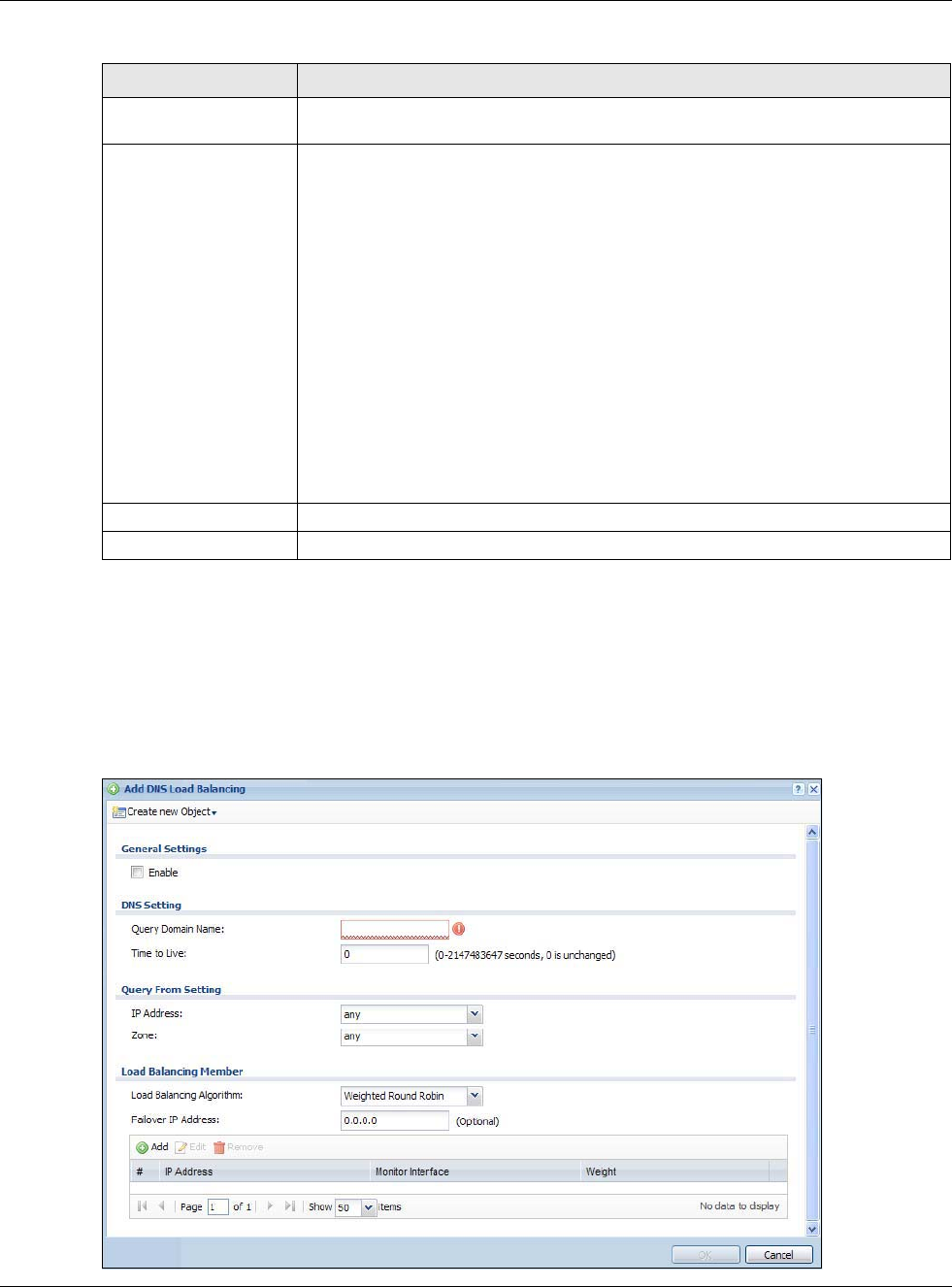
Figure 202 Configuration > Network > Inbound LB > Add
Load Balancing Member This field displays the member interfaces which the USG manages for load
balancing.
Algorithm This field displays the load balancing method the USG uses for this DNS load
balancing rule.
Weighted Round Robin - Each member interface is assigned a weight. An
interface with a larger weight gets more chances to transmit traffic than an interface
with a smaller weight. For example, if the weight ratio of wan1 and wan2 interfaces
is 2:1, the USG chooses wan1 for 2 sessions’ traffic and wan2 for 1 session’s traffic
in each round of 3 new sessions.
Least Connection - The USG chooses choose a member interface which is handling
the least number of sessions.
Least Load - Outbound - The USG chooses a member interface which is handling
the least amount of outgoing traffic.
Least Load - Inbound - The USG chooses a member interface which is handling
the least amount of incoming traffic.
Least Load - Total - The USG chooses a member interface which is handling the
least amount of outgoing and incoming traffic.
Apply Click this button to save your changes to the USG.
Reset Click this button to return the screen to its last-saved settings.
Table 117 Configuration > Network > Inbound LB (continued)
LABEL DESCRIPTION
Chapter 18 Inbound Load Balancing
USG20(W)-VPN Series User’s Guide
294
The following table describes the labels in this screen.
Table 118 Configuration > Network > Inbound LB > Add/Edit
LABEL DESCRIPTION
Create New Object Use this to configure any new setting objects that you need to use in this screen.
General Settings
Enable Select this to enable this DNS load balancing rule.
DNS Setting
Query Domain Name Type up to 255 characters for a domain name for which you want the USG to manage
DNS load balancing. You can use a wildcard (*) to let multiple domains match the
name. For example, use *.example.com to specify any domain name that ends with
“example.com” would match.
Time to Live Enter the number of seconds the USG recommends DNS request hosts to keep the
DNS entry in their caches before removing it. Enter 0 to have the USG not
recommend this so the DNS request hosts will follow their DNS server’s TTL setting.
Query From Setting
IP Address Enter the IP address of a computer or a DNS server which makes the DNS queries
upon which to apply this rule.
DNS servers process client queries using recursion or iteration:
• In recursion, DNS servers make recursive queries on behalf of clients. So you
have to configure this field to the DNS server’s IP address when recursion is
used.
• In iteration, a client asks the DNS server and expects the best and immediate
answer without the DNS server contacting other DNS servers. If the primary DNS
server cannot provide the best answer, the client makes iteration queries to other
configured DNS servers to resolve the name. You have to configure this field to
the client’s IP address when iteration is used.
Zone Select the zone of DNS query messages upon which to apply this rule.
Load Balancing
Member
Load Balancing
Algorithm Select a load balancing method to use from the drop-down list box.
Select Weighted Round Robin to balance the traffic load between
interfaces based on their respective weights. An interface with a larger
weight gets more chances to transmit traffic than an interface with a
smaller weight. For example, if the weight ratio of wan1 and wan2
interfaces is 2:1, the USG chooses wan1 for 2 sessions’ traffic and wan2 for
every session’s traffic in each round of 3 new sessions.
Select Least Connection to have the USG choose the member interface which is
handling the least number of sessions.
Select Least Load - Outbound to have the USG choose the member interface which
is handling the least amount of outgoing traffic.
Select Least Load - Inbound to have the USG choose the member interface which
is handling the least amount of incoming traffic.
Select Least Load - Total to have the USG choose the member interface which is
handling the least amount of outgoing and incoming traffic.
Failover IP Address Enter an alternate IP address with which the USG will respond to a DNS query
message when the load balancing algorithm cannot find any available interface.
Add Click this to create a new member interface for this rule.
Edit Double-click an entry or select it and click Edit to open a screen where you can
modify the entry’s settings.
Chapter 18 Inbound Load Balancing
USG20(W)-VPN Series User’s Guide
295
18.2.2 The Inbound LB Member Add/Edit Screen
The Add Load Balancing Member screen allows you to add a member interface for the DNS load
balancing rule. Click Configuration > Network > Inbound LB > Add or Edit and then an Add or
Edit icon to open this screen.
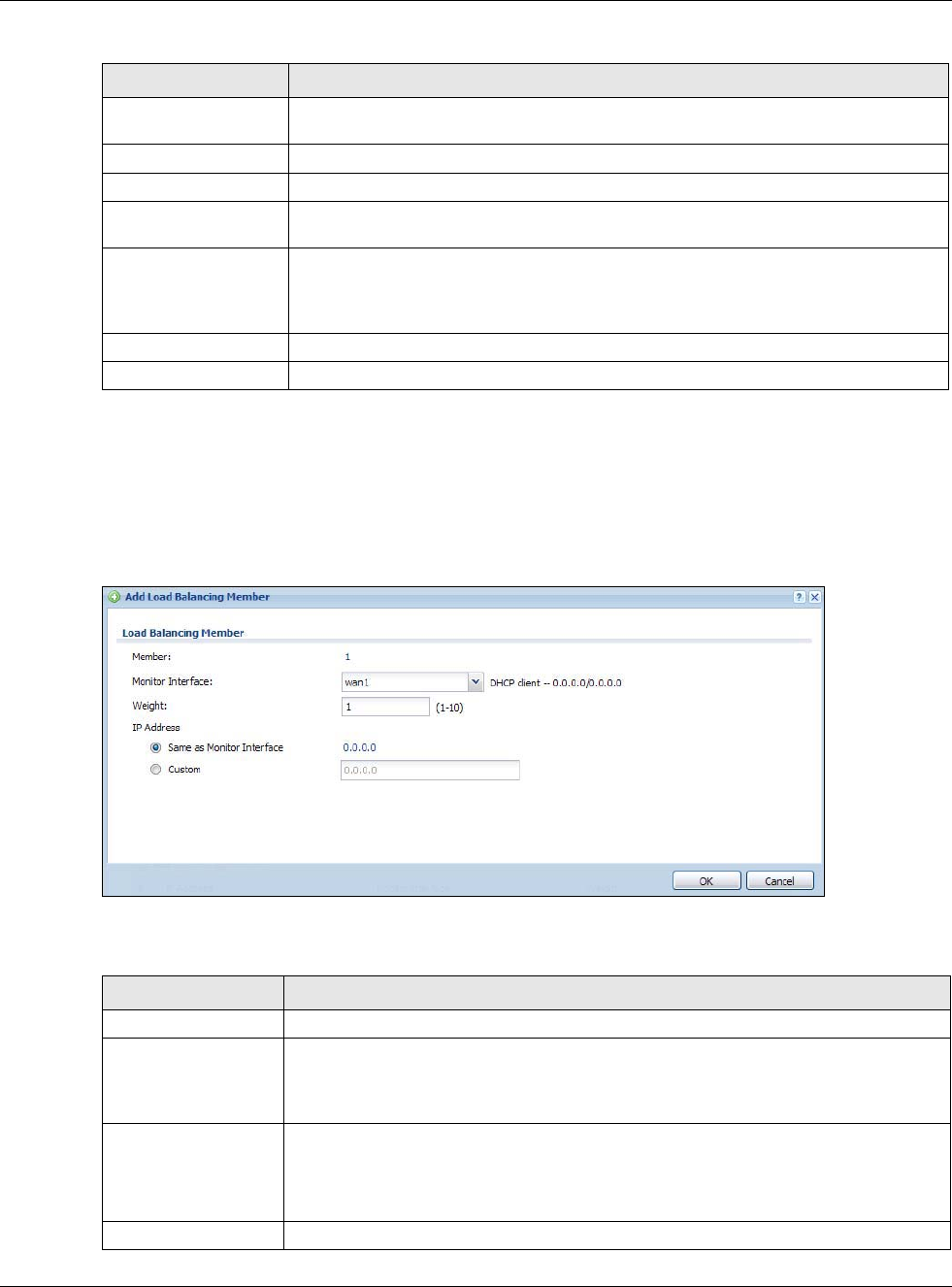
Figure 203 Configuration > Network > Inbound LB > Add/Edit > Add
The following table describes the labels in this screen.
Remove To remove an entry, select it and click Remove. The USG confirms you want to
remove it before doing so.
# This field displays the order in which the USG checks this rule’s member interfaces.
IP Address This field displays the IP address of the member interface.
Monitor Interface This field displays the name of the member interface. The USG manages load
balancing between the member interfaces.
Weight This field is available if you selected Weighted Round Robin as the load balancing
algorithm. This field displays the weight of the member interface. An interface with a
larger weight gets more chances to transmit traffic than an interface with a smaller
weight.
OK Click OK to save your changes back to the USG.
Cancel Click Cancel to exit this screen without saving.
Table 118 Configuration > Network > Inbound LB > Add/Edit (continued)
LABEL DESCRIPTION
Table 119 Configuration > Network > Inbound LB > Add/Edit > Add/Edit
LABEL DESCRIPTION
Member The USG checks each member interface’s loading in the order displayed here.
Monitor Interface Select an interface to associate it with the DNS load balancing rule. This field also
displays whether the IP address is a static IP address (Static), dynamically assigned
(Dynamic) or obtained from a DHCP server (DHCP Client), as well as the IP address
and subnet mask.
Weight This field is available if you selected Weighted Round Robin for the load balancing
algorithm.
Specify the weight of the member interface. An interface with a larger weight gets
more chances to transmit traffic than an interface with a smaller weight.
IP Address
Chapter 18 Inbound Load Balancing
USG20(W)-VPN Series User’s Guide
296
Same as Monitor
Interface
Select this to send the IP address displayed in the Monitor Interface field to the
DNS query senders.
Custom Select this and enter another IP address to send to the DNS query senders.
OK Click OK to save your changes back to the USG.
Cancel Click Cancel to exit this screen without saving.
Table 119 Configuration > Network > Inbound LB > Add/Edit > Add/Edit (continued)
LABEL DESCRIPTION
USG20(W)-VPN Series User’s Guide
297
CHAPTER 19
Web Authentication
19.1 Web Auth Overview
Web authentication can intercept network traffic, according to the authentication policies, until the
user authenticates his or her connection, usually through a specifically designated login web page.
This means all web page requests can initially be redirected to a special web page that requires
users to authenticate their sessions. Once authentication is successful, they can then connect to the
rest of the network or Internet.
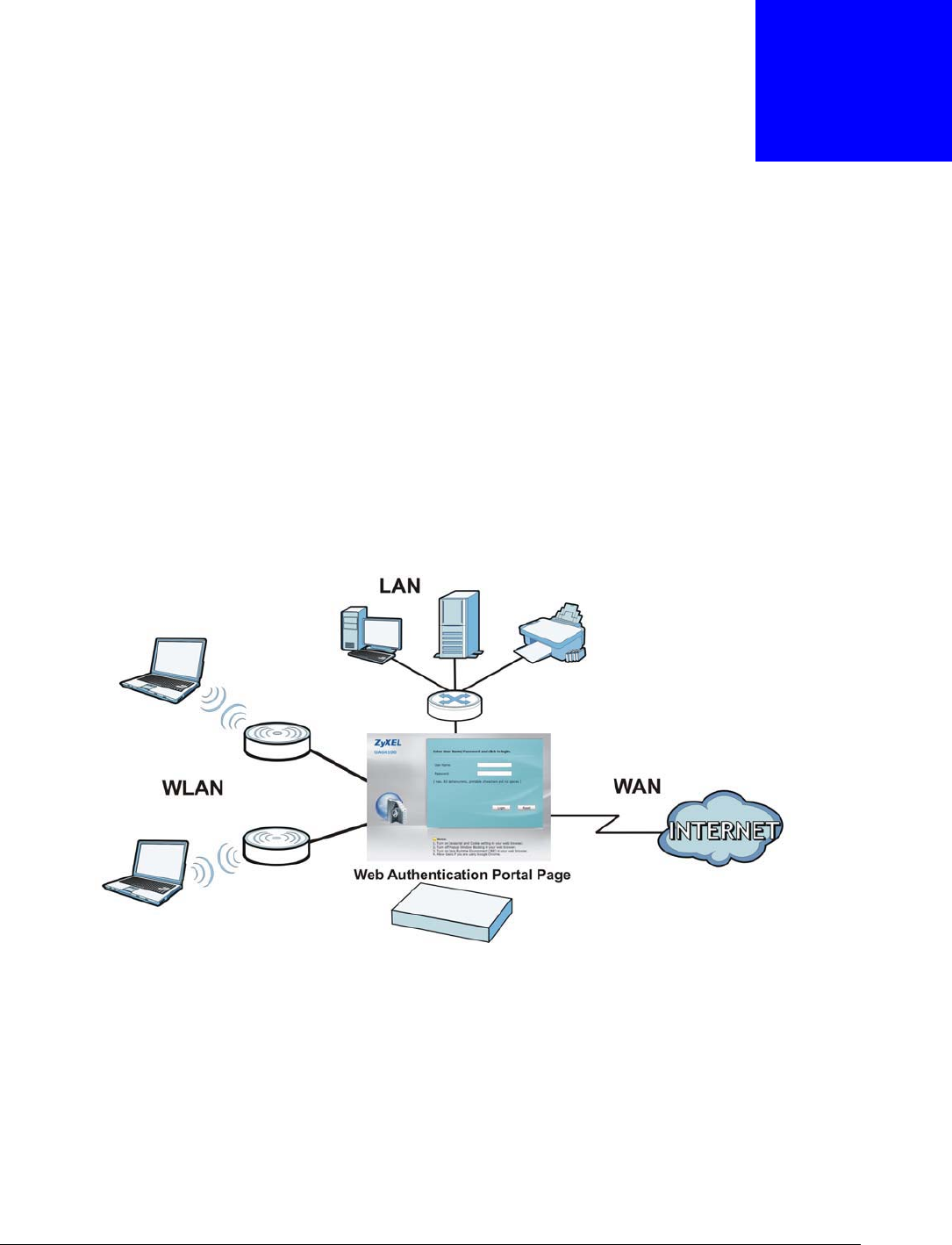
As soon as a user attempt to open a web page, the USG reroutes his/her browser to a web portal
page that prompts him/her to log in.
Figure 204 Web Authentication Example
The web authentication page only appears once per authentication session. Unless a user session
times out or he/she closes the connection, he or she generally will not see it again during the same
session.
19.1.1 What You Can Do in this Chapter
•Use the Configuration > Web Authentication screens (Section 19.2 on page 298) to create
and manage web authentication policies.
•Use the Configuration > Web Authentication > SSO screen (Section 19.3 on page 302) to
configure how the USG communictates with a Single Sign-On agent.

Chapter 19 Web Authentication
USG20(W)-VPN Series User’s Guide
298
19.1.2 What You Need to Know
Single Sign-On
A SSO (Single Sign On) agent integrates Domain Controller and USG authentication mechanisms,
so that users just need to log in once (single) to get access to permitted resources.
Forced User Authentication
Instead of making users for which user-aware policies have been configured go to the USG Login
screen manually, you can configure the USG to display the Login screen automatically whenever it
routes HTTP traffic for anyone who has not logged in yet.
Note: This works with HTTP traffic only. The USG does not display the Login screen when
users attempt to send other kinds of traffic.
The USG does not automatically route the request that prompted the login, however, so users have
to make this request again.
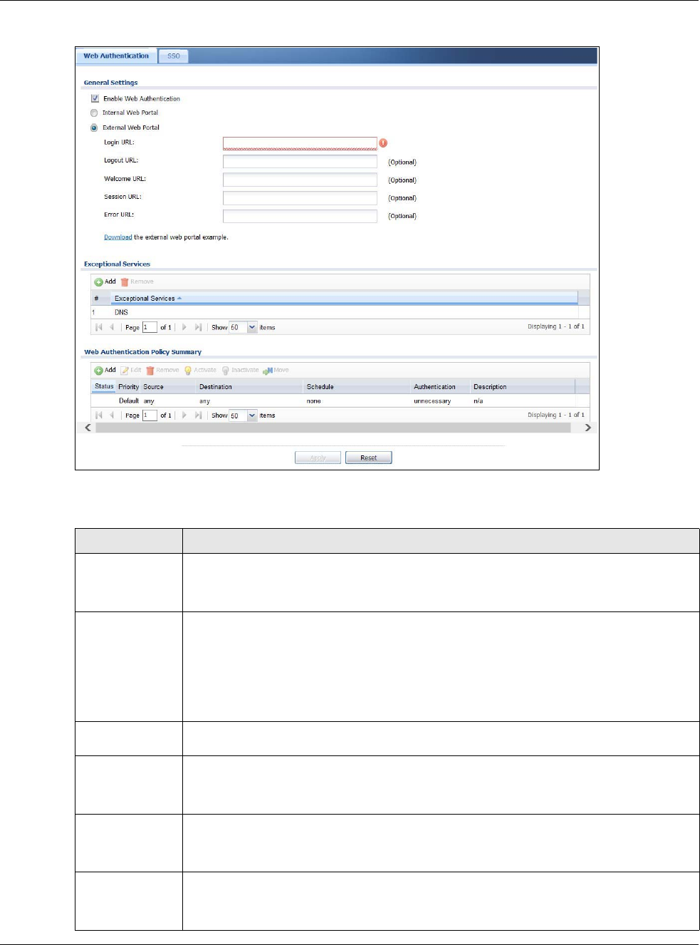
19.2 Web Authentication Screen
The Web Authentication screen displays the web portal settings and web authentication policies
you have configured on the USG. The screen differs depending on what you select in the
Authentication field.
Click Configuration > Web Authentication to display the screen.
Chapter 19 Web Authentication
USG20(W)-VPN Series User’s Guide
299
Figure 205 Configuration > Web Authentication (Web Portal)
The following table gives an overview of the objects you can configure.
Table 120 Configuration > Web Authentication
LABEL DESCRIPTION
Enable Web
Authentication
Select Enable Web Authentication to turn on the web authentication feature.
Once enabled, all network traffic is blocked until a client authenticates with the USG
through the specifically designated web portal.
Internal Web
Portal
Select this to use the default login page built into the USG. If you later assign a custom
login page, you can still return to the USG’s default page as it is saved indefinitely.
The login page appears whenever the web portal intercepts network traffic, preventing
unauthorized users from gaining access to the network.
You can customize the login page built into the USG in the System > WWW > Login
Page screen.
External Web
Portal
Select this to use a custom login page from an external web portal instead of the default
one built into the USG. You can configure the look and feel of the web portal page.
Login URL Specify the login page’s URL; for example, http://IIS server IP Address/login.html.
The Internet Information Server (IIS) is the web server on which the web portal files are
installed.
Logout URL Specify the logout page’s URL; for example, http://IIS server IP Address/logout.html.
The Internet Information Server (IIS) is the web server on which the web portal files are
installed.
Welcome URL Specify the welcome page’s URL; for example, http://IIS server IP Address/welcome.html.
The Internet Information Server (IIS) is the web server on which the web portal files are
installed.

Chapter 19 Web Authentication
USG20(W)-VPN Series User’s Guide
300
Session URL Specify the session page’s URL; for example, http://IIS server IP Address/session.html.
The Internet Information Server (IIS) is the web server on which the web portal files are
installed.
Error URL Specify the error page’s URL; for example, http://IIS server IP Address/error.html.
The Internet Information Server (IIS) is the web server on which the web portal files are
installed.
Download Click this to download an example web portal file for your reference.
Exceptional
Services
Use this table to list services that users can access without logging in. In the list, select
one or more entries and click Remove to delete it or them. Keeping DNS as a member
allows users’ computers to resolve domain names into IP addresses. Click Add to add new
services that users can access without logging in.
Web
Authentication
Policy Summary
Use this table to manage the USG’s list of web authentication policies.
Add Click this to create a new entry. Select an entry and click Add to create a new entry after
the selected entry.
Edit Double-click an entry or select it and click Edit to open a screen where you can modify the
entry’s settings.
Remove To remove an entry, select it and click Remove. The USG confirms you want to remove it
before doing so.
Activate To turn on an entry, select it and click Activate.
Inactivate To turn off an entry, select it and click Inactivate.
Move To move an entry to a different number in the list, click the Move icon. In the field that
appears, specify the number to which you want to move the interface.
Status This icon is lit when the entry is active and dimmed when the entry is inactive.
Priority This is the position of the authentication policy in the list. The priority is important as the
policies are applied in order of priority. Default displays for the default authentication
policy that the USG uses on traffic that does not match any exceptional service or other
authentication policy. You can edit the default rule but not delete it.
Source This displays the source address object to which this policy applies.
Destination This displays the destination address object to which this policy applies.
Schedule This field displays the schedule object that dictates when the policy applies. none means
the policy is active at all times if enabled.
Authentication This field displays the authentication requirement for users when their traffic matches this
policy.
unnecessary - Users do not need to be authenticated.
required - Users need to be authenticated. They must manually go to the login screen.
The USG will not redirect them to the login screen.
force - Users need to be authenticated. The USG automatically displays the login screen
whenever it routes HTTP traffic for users who have not logged in yet.
Description If the entry has a description configured, it displays here. This is n/a for the default policy.
Apply Click this button to save your changes to the USG.
Reset Click this button to return the screen to its last-saved settings.
Table 120 Configuration > Web Authentication (continued)
LABEL DESCRIPTION
Chapter 19 Web Authentication
USG20(W)-VPN Series User’s Guide
301
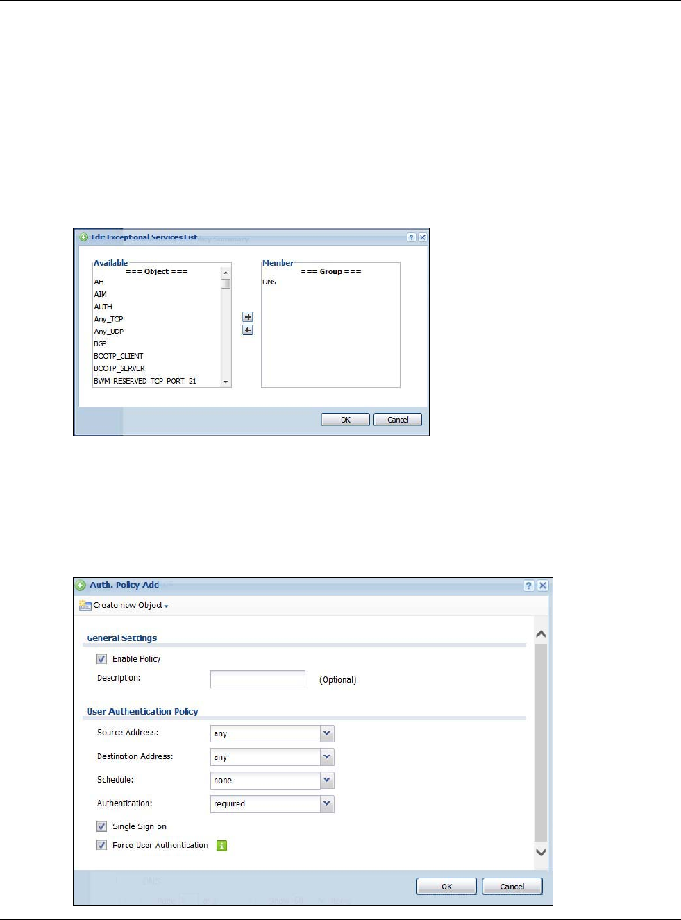
19.2.1 Creating Exceptional Services
This screen lists services that users can access without logging in. Click Add under Exceptional
Services in the previous screen to display this screen. You can change the list’s membership here.
Available services appear on the left. Select any services you want users to be able to access
without logging in and click the right arrow button -> to add them. The member services are on the
right. Select any service that you want to remove from the member list, and click the left arrow <-
button to remove them. Then click OK to apply the changes and return to the main Web
Authentication screen. Alternatively, click Cancel to discard the changes and return to the main
Web Authentication screen.
Figure 206 Configuration > Web Authentication > Add Exceptional Service
19.2.2 Creating/Editing an Authentication Policy
Click Configuration > Web Authentication and then the Add (or Edit) icon in the Web
Authentication Policy Summary section to open the Auth. Policy Add/Edit screen. Use this
screen to configure an authentication policy.
Figure 207 Configuration > Web Authentication > Add Authentication Policy
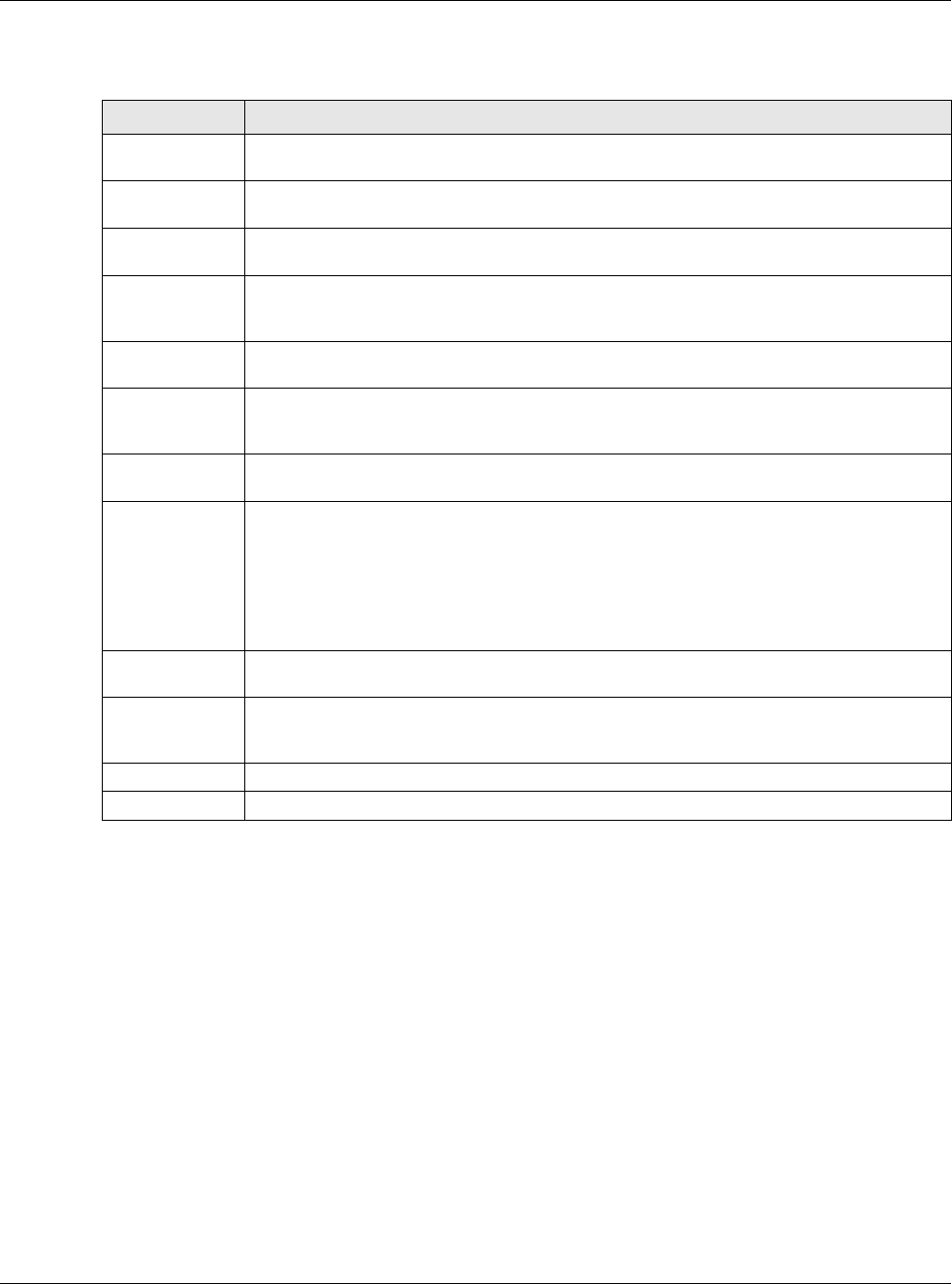
Chapter 19 Web Authentication
USG20(W)-VPN Series User’s Guide
302
The following table gives an overview of the objects you can configure.
19.3 SSO Overview
The SSO (Single Sign-On) function integrates Domain Controller and USG authentication
mechanisms, so that users just need to log in once (single login) to get access to permitted
resources.
In the following figure, U user logs into a Domain Controller (DC) which passes the user’s login
credentials to the SSO agent. The SSO agent checks that these credentials are correct with the AD
server, and if the AD server confirms so, the SSO then notifies the USG to allow access for the user
to the permitted resource (Internet access, for example).
Table 121 Configuration > Web Authentication > Add Authentication Policy
LABEL DESCRIPTION
Create new
Object
Use to configure any new settings objects that you need to use in this screen. Select
Address or Schedule.
Enable Policy Select this check box to activate the authentication policy. This field is available for user-
configured policies.
Description Enter a descriptive name of up to 60 printable ASCII characters for the policy. Spaces are
allowed. This field is available for user-configured policies.
User
Authentication
Policy
Use this section of the screen to determine which traffic requires (or does not require) the
senders to be authenticated in order to be routed.
Source Address Select a source address or address group for whom this policy applies. Select any if the
policy is effective for every source. This is any and not configurable for the default policy.
Destination
Address
Select a destination address or address group for whom this policy applies. Select any if
the policy is effective for every destination. This is any and not configurable for the default
policy.
Schedule Select a schedule that defines when the policy applies. Otherwise, select none and the rule
is always effective. This is none and not configurable for the default policy.
Authentication Select the authentication requirement for users when their traffic matches this policy.
unnecessary - Users do not need to be authenticated.
required - Users need to be authenticated. If Force User Authentication is selected, all
HTTP traffic from unauthenticated users is redirected to a default or user-defined login
page. Otherwise, they must manually go to the login screen. The USG will not redirect
them to the login screen.
Single Sign-on This field is available for user-configured policies that require Single Sign-On (SSO). Select
this to have the USG enable the SSO feature. You can set up this feature in the SSO screen.
Force User
Authentication
This field is available for user-configured policies that require authentication. Select this to
have the USG automatically display the login screen when users who have not logged in yet
try to send HTTP traffic.
OK Click OK to save your changes back to the USG.
Cancel Click Cancel to exit this screen without saving.
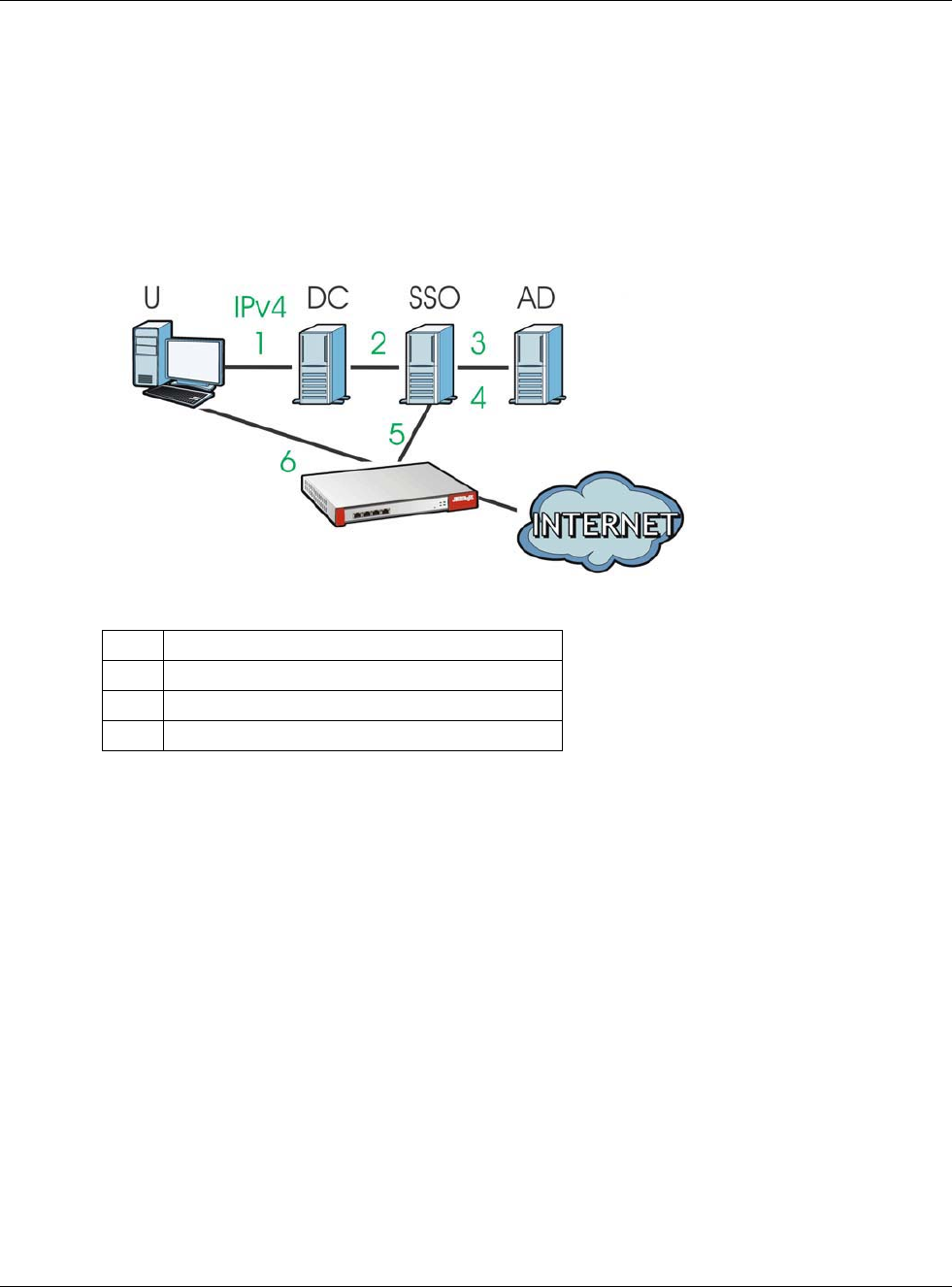
Chapter 19 Web Authentication
USG20(W)-VPN Series User’s Guide
303
Note: The USG, the DC, the SSO agent and the AD server must all be in the same domain
and be able to communicate with each other.
SSO does not support IPv6, LDAP or RADIUS; you must use it in an IPv4 network
environment with Windows AD (Active Directory) authentication database.
You must enable Web Authentication in the Configuration > Web Authentication
screen.
Figure 208 SSO Overview
Install the SSO Agent on one of the following platforms:
• Windows 7 Professional (32-bit and 64-bit)
• Windows Server 2008 Enterprise (32-bit and 64-bit)
• Windows 2008 R2 (64-bit)
• Windows Server 2012 (64-bit)
UUser
DC Domain Controller
SSO Single Sign-On agent
AD Active Directory
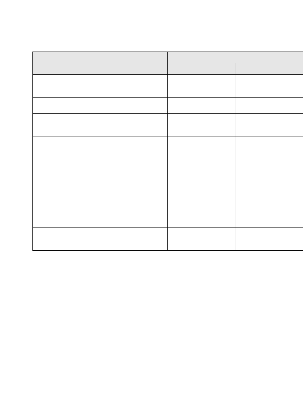
Chapter 19 Web Authentication
USG20(W)-VPN Series User’s Guide
304
19.4 SSO - USG Configuration
This section shows what you have to do on the USG in order to use SSO.
19.4.1 Configuration Overview
These are the screens you need to configure:
•Configure the USG to Communicate with SSO on page 304
•Enable Web Authentication on page 305
•Create a Security Policy on page 306
•Configure User Information on page 307
•Configure an Authentication Method on page 308
•Configure Active Directory on page 309 or Configure Active Directory on page 309
19.4.2 Configure the USG to Communicate with SSO
Use Configuration > Web Authentication > SSO to configure how the USG communicates with
the Single Sign-On (SSO) agent.
Table 122 USG - SSO Agent Field Mapping
USG SSO
SCREEN FIELD SCREEN FIELD
Web Authentication >
SSO
Listen Port Agent Configuration
Page > Gateway
Setting
Gateway Port
Web Authentication >
SSO
Primary Agent Port Agent Configuration
Page
Agent Listening Port
Object > User/Group
> User > Add
Group Identifier Agent Configuration
Page > Configure
LDAP/AD Server
Group Membership
Object > AAA Server >
Active Directory > Add
Base DN Agent Configuration
Page > Configure
LDAP/AD Server
Base DN
Object > AAA Server >
Active Directory > Add
Bind DN Agent Configuration
Page > Configure
LDAP/AD Server
Bind DN
Object > User/Group
> User > Add
User Name Agent Configuration
Page > Configure
LDAP/AD Server
Login Name Attribute
Object > AAA Server >
Active Directory > Add
Server Address Agent Configuration
Page > Configure
LDAP/AD Server
Server Address
Network > Interface >
Ethernet > wan (IPv4)
IP address Agent Configuration
Page > Gateway
Setting
Gateway IP
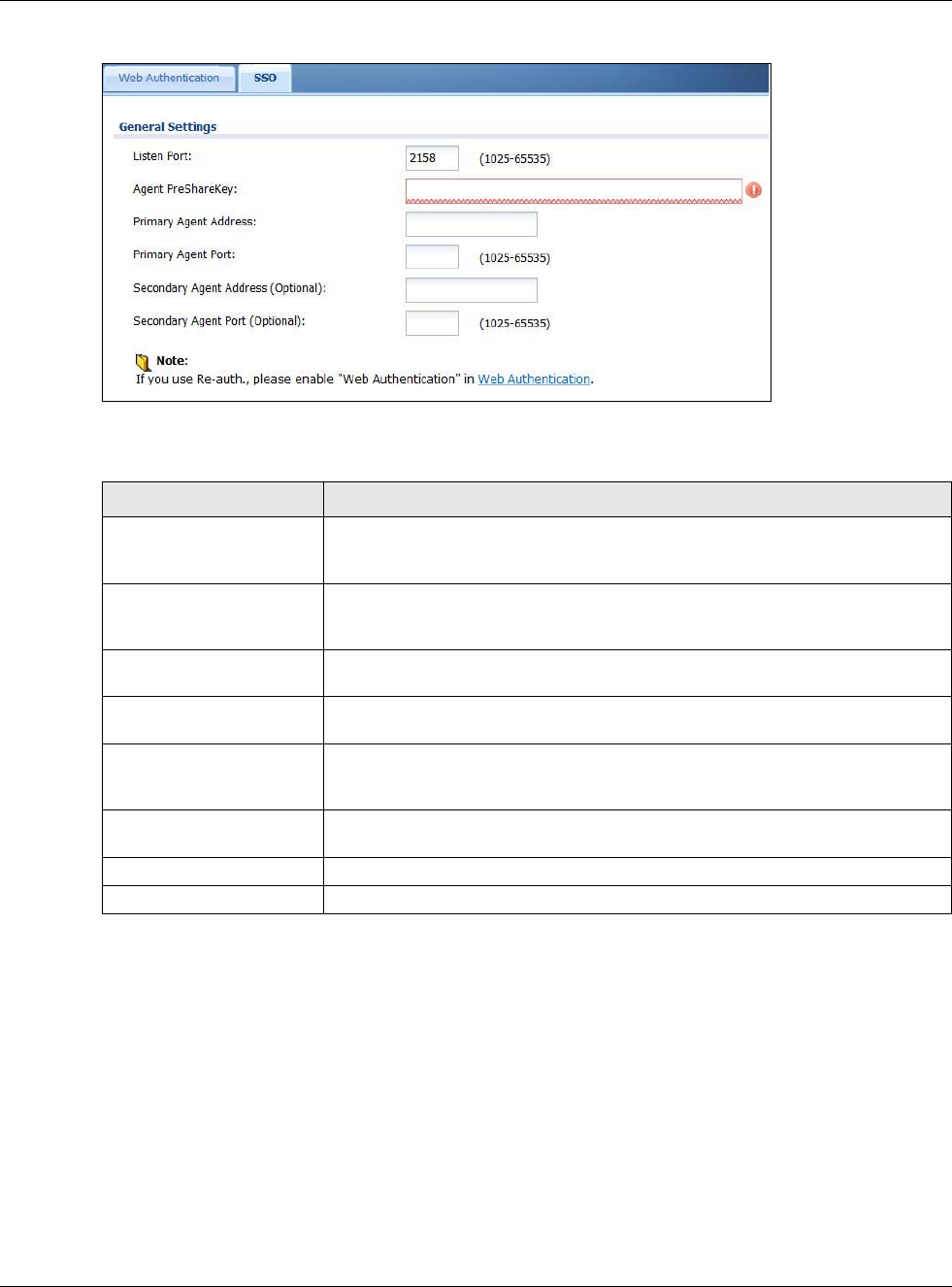
Chapter 19 Web Authentication
USG20(W)-VPN Series User’s Guide
305
Figure 209 Configuration > Web Authentication > SSO
The following table gives an overview of the objects you can configure.
19.4.3 Enable Web Authentication
Enable Web Authentication and add a web authentication policy.
Table 123 Configuration > Web Authentication > SSO
LABEL DESCRIPTION
Listen Port The default agent listening port is 2158. If you change it on the USG, then
change it to the same number in the Gateway Port field on the SSO agent too.
Type a number ranging from 1025 to 65535.
Agent PreShareKey Type 8-32 printable ASCII characters or exactly 32 hex characters (0-9; a-f).
The Agent PreShareKey is used to encrypt communications between the USG
and the SSO agent.
Primary Agent Address Type the IPv4 address of the SSO agent. The USG and the SSO agent must be in
the same domain and be able to communicate with each other.
Primary Agent Port Type the same port number here as in the Agent Listening Port field on the
SSO agent. Type a number ranging from 1025 to 65535.
Secondary Agent Address
(Optional)
Type the IPv4 address of the backup SSO agent if there is one. The USG and the
backup SSO agent must be in the same domain and be able to communicate
with each other.
Secondary Agent Port
(Optional)
Type the same port number here as in the Agent Listening Port field on the
backup SSO agent if there is one. Type a number ranging from 1025 to 65535.
Apply Click this button to save your changes to the USG.
Reset Click this button to return the screen to its last-saved settings
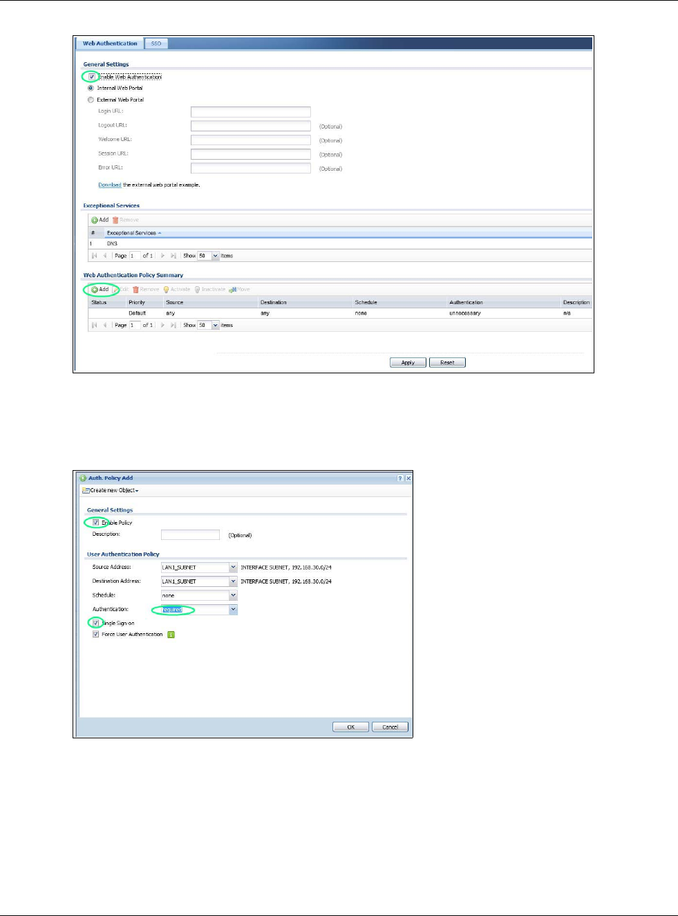
Chapter 19 Web Authentication
USG20(W)-VPN Series User’s Guide
306
Make sure you select Enable Policy, Single Sign-On and choose required in Authentication.
Do NOT select any as the source address unless you want all incoming connections to be
authenticated!
See Table 120 on page 299 and Table 121 on page 302 for more information on configuring these
screens.
19.4.4 Create a Security Policy
Configure a Security Policy for SSO traffic source and destination direction in order to prevent the
security policy from blocking this traffic. Go to Configuration > Security Policy > Policy and add
a new policy if a default one does not cover the SSO web authentication traffic direction.
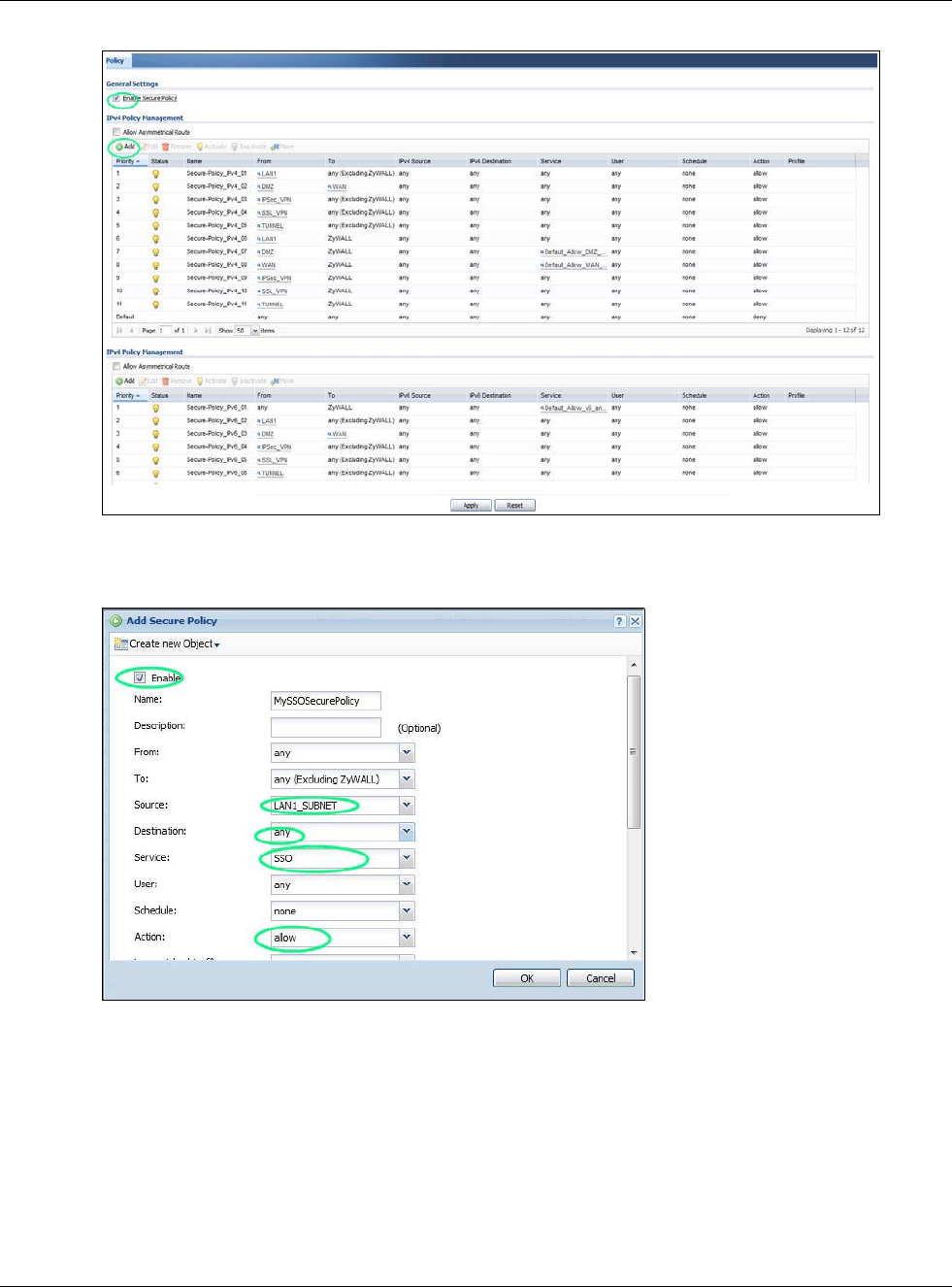
Chapter 19 Web Authentication
USG20(W)-VPN Series User’s Guide
307
Configure the fields as shown in the following screen. Configure the source and destination
addresses according to the SSO web authrntication traffic in your network.
19.4.5 Configure User Information
Configure a User account of the ext-group-user type.
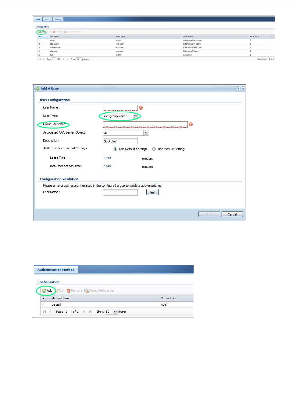
Chapter 19 Web Authentication
USG20(W)-VPN Series User’s Guide
308
Configure Group Identifier to be the same as Group Membership on the SSO agent.
19.4.6 Configure an Authentication Method
Configure Active Directory (AD) for authentication with SSO.
Choose group ad as the authentication server for SSO.
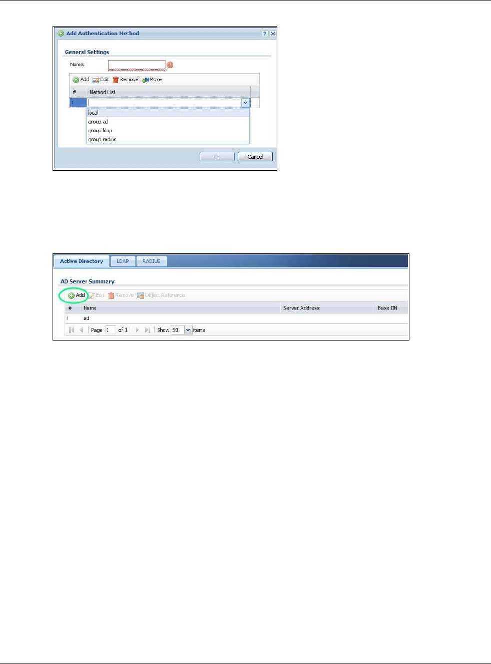
Chapter 19 Web Authentication
USG20(W)-VPN Series User’s Guide
309
19.4.7 Configure Active Directory
You must configure an Active Directory (AD) server in AAA Setup to be the same as AD configured
on the SSO agent.
The default AD server port is 389. If you change this, make sure you make the same changes on
the SSO. Configure the Base DN exactly the same as on the Domain Controller and SSO. Bind DN
is a user name and password that allows the USG to join the domain with administrative privileges.
It is a required field.
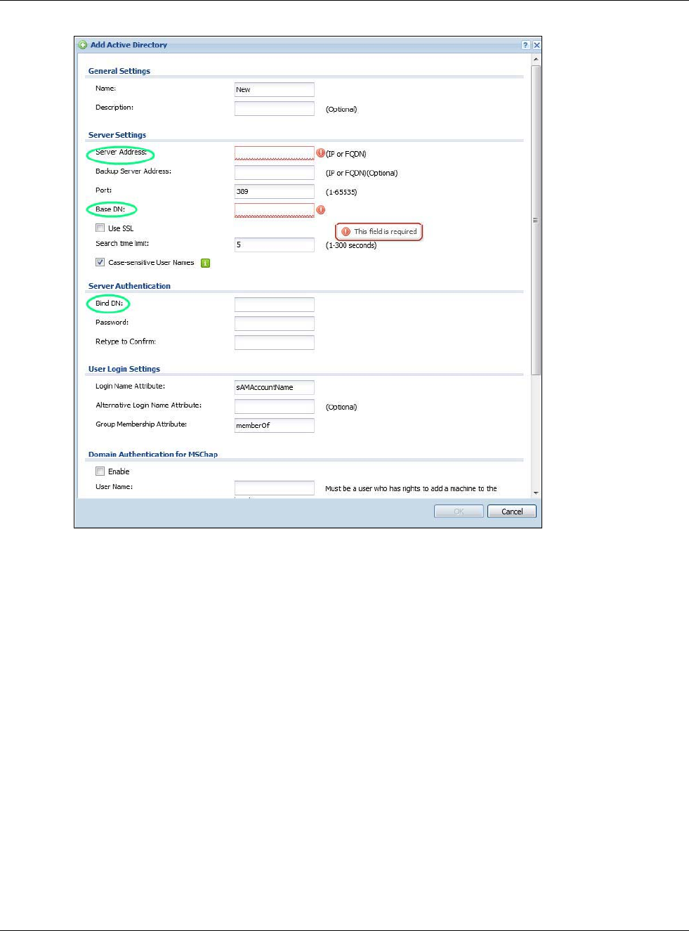
Chapter 19 Web Authentication
USG20(W)-VPN Series User’s Guide
310
19.5 SSO Agent Configuration
This section shows what you have to do on the SSO agent in order to work with the USG.
After you install the SSO agent, you will see an icon in the system tray (bottom right of the screen)
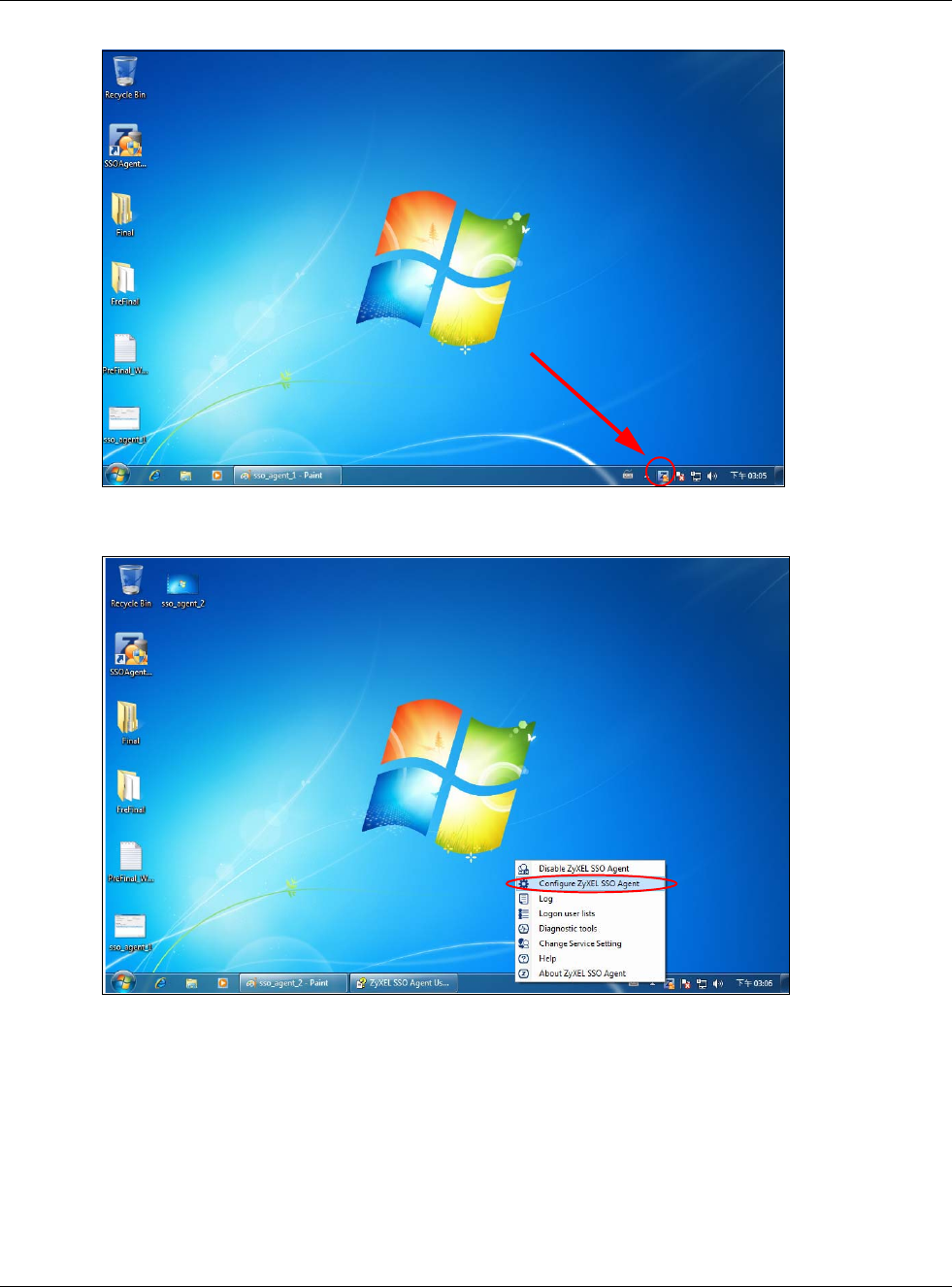
Chapter 19 Web Authentication
USG20(W)-VPN Series User’s Guide
311
Right-click the SSO icon and select Configure ZyXEL SSO Agent.
Configure the Agent Listening Port, AD server exactly as you have done on the USG. Add the
USG IP address as the Gateway. Make sure the USG and SSO agent are able to communicate with
each other.
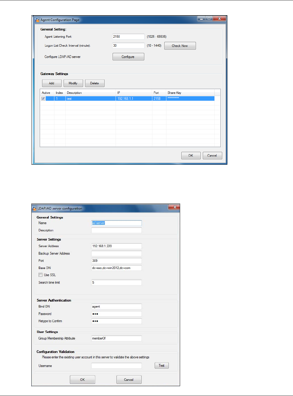
Chapter 19 Web Authentication
USG20(W)-VPN Series User’s Guide
312
Configure the Server Address, Port, Base DN, Bind DN, Login Name Attribute and Group
Membership for the AD server settings exactly as you have done on the USG. Group
Membership is called Group Identifier on the USG.
LDAP/AD Server Configuration
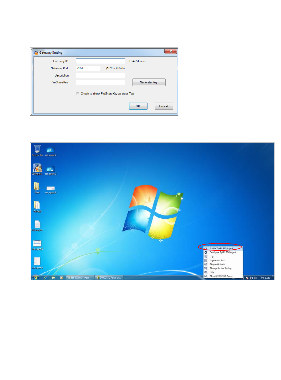
Chapter 19 Web Authentication
USG20(W)-VPN Series User’s Guide
313
Configure the Gateway IP address, Gateway Port and PreShareKey exactly as you have done in
the USG Configuration > Web Authentication > SSO screen. If you want to use Generate Key
to have the SSO create a random password, select Check to show PreShareKey as clear Text so
as to see the password, then copy and paste it to the USG.
After all SSO agent configurations are done, right-click the SSO icon in the system tray and select
Enable ZyXEL SSO Agent.
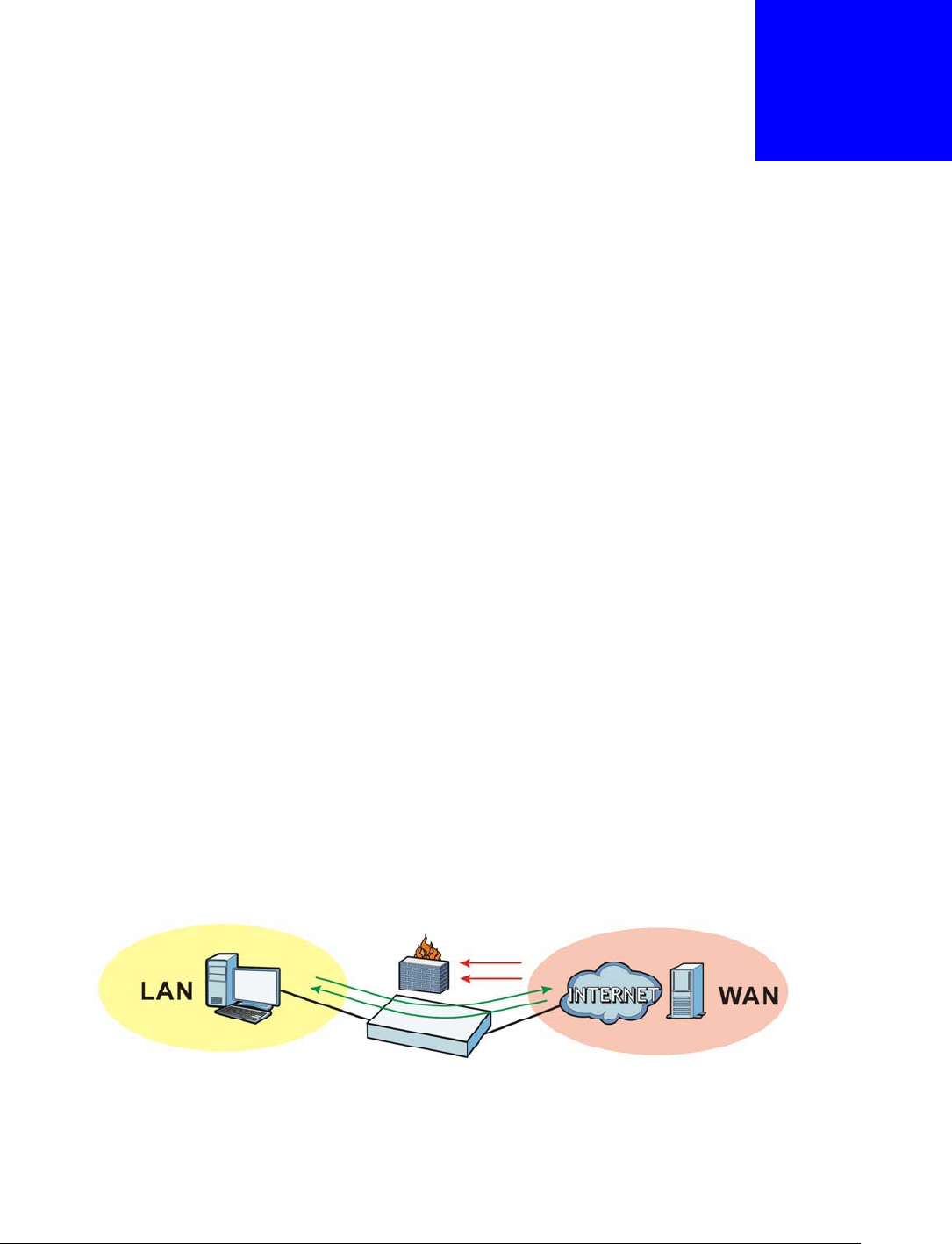
USG20(W)-VPN Series User’s Guide
314
CHAPTER 20
Security Policy
20.1 Overview
A security policy is a template of security settings that can be applied to specific traffic at specific
times. The policy can be applied:
• to a specific direction of travel of packets (from / to)
• to a specific source and destination address objects
• to a specific type of traffic (services)
• to a specific user or group of users
• at a specific schedule
The policy can be configured:
• to allow or deny traffic that matches the criteria above
• send a log or alert for traffic that matches the criteria above
• to apply the actions configured in the UTM profile (content filter, ) to traffic that matches the
criteria above
Note: Security policies can be applied to both IPv4 and IPv6 traffic.
The security policies can also limit the number of user sessions.
The following example shows the USG’s default security policies behavior for a specific direction of
travel of packets. WAN to LAN traffic and how stateful inspection works. A LAN user can initiate a
Telnet session from within the LAN zone and the USG allows the response. However, the USG blocks
incoming Telnet traffic initiated from the WAN zone and destined for the LAN zone.
Figure 210 Default Directional Security Policy Example
20.2 One Security
OneSecurity.com is a website with guidance on configuration walkthroughs, troubleshooting, and
other information.
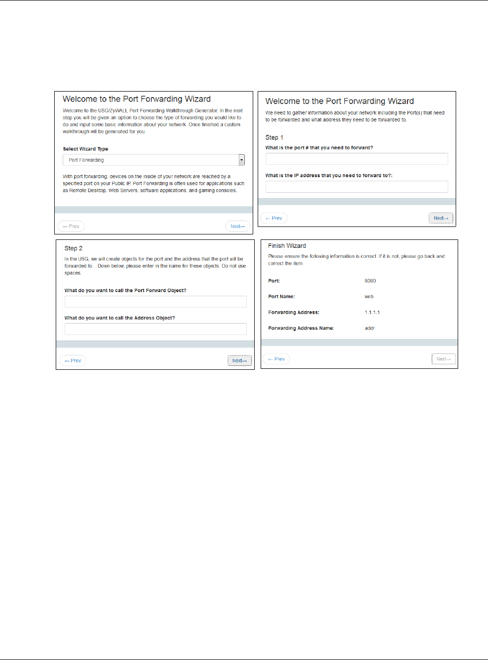
Chapter 20 Security Policy
USG20(W)-VPN Series User’s Guide
315
Note: Note that the walkthroughs do not perform the actual configuring, but just show
you how to do it.
This is an example of a port forwarding configuration walkthrough.
Figure 211 Example of a Port Forwarding Configuration Walkthrough.
This is an example of L2TP over IPSec VPN Troubleshooting troubleshooting.
12
34
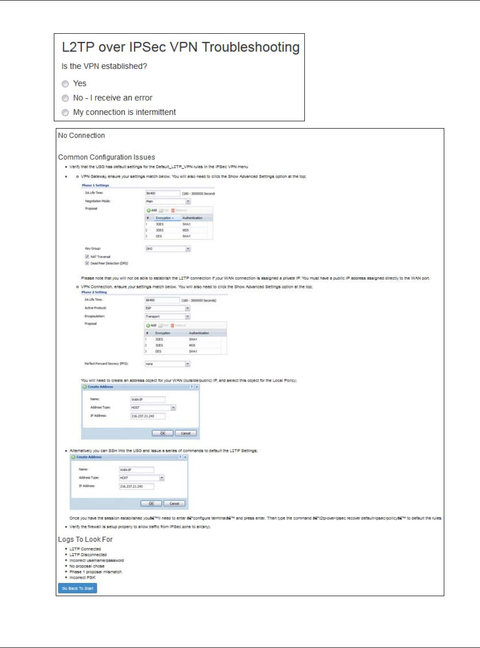
Chapter 20 Security Policy
USG20(W)-VPN Series User’s Guide
316
Figure 212 Example of L2TP over IPSec Troubleshooting - 1
1
2
2
3
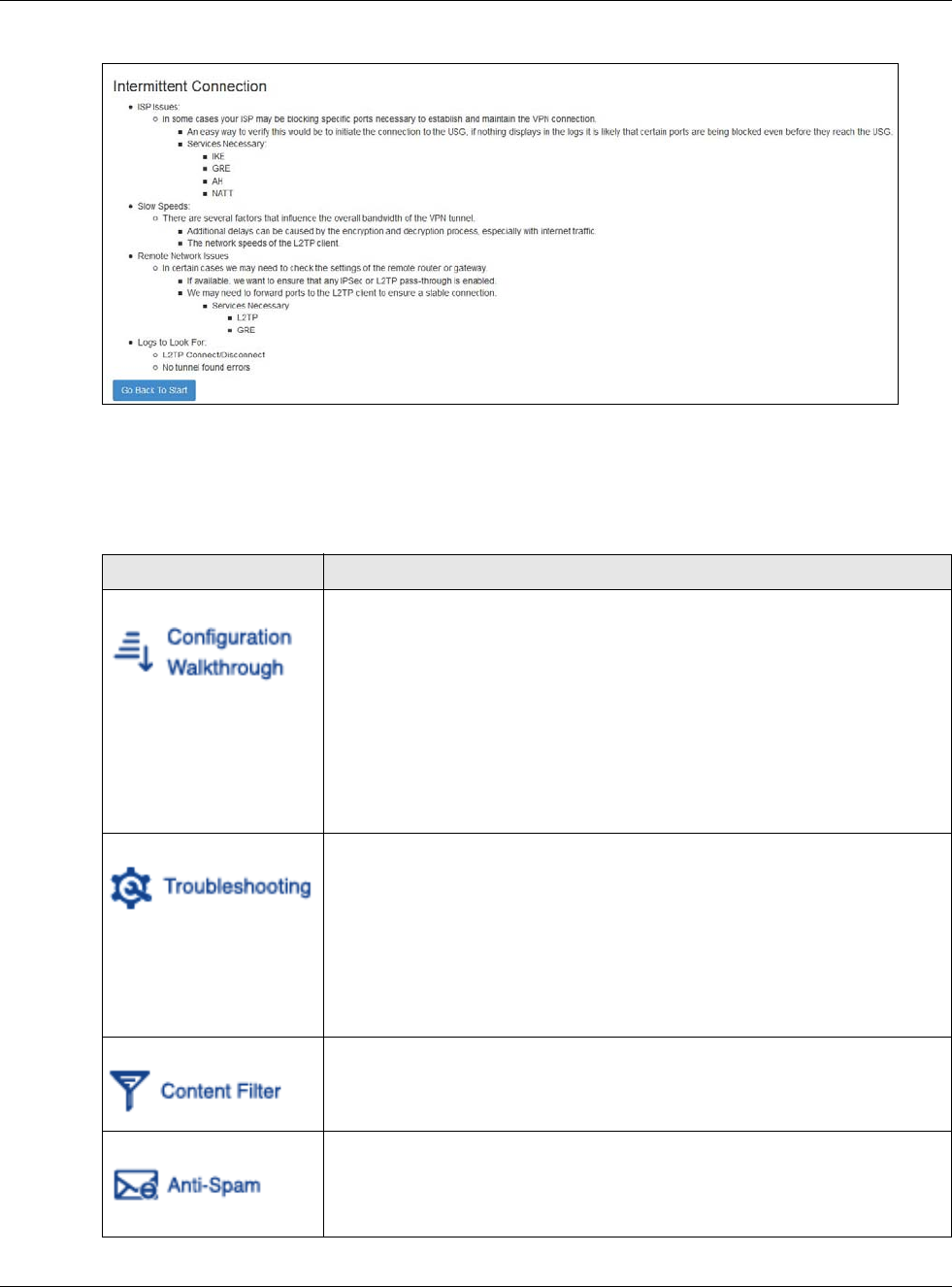
Chapter 20 Security Policy
USG20(W)-VPN Series User’s Guide
317
Figure 213 Example of L2TP over IPSec Troubleshooting - 2
In the USG, you will see icons that link to OneSecurity walkthroughs, troubleshooting and so on in
certain screens.
For example, at the time of writing, these are the OneSecurity icons you can see.
Table 124 OneSecurity Icons
ONESECURITY ICON SCREEN
Click this icon to go to a series of screens that guide you how to configure the
feature. Note that the walkthroughs do not perform the actual configuring, but
just show you how to do it.
•Licensing > Registration
• Network > NAT
• Network > Routing > Policy Route
• UTM Profile > Content Filter
•UTM Profile > Anti-Spam
• VPN > IPSec VPN
•VPN > SSL VPN
•VPN > L2TP VPN
Click this icon to go to a series of screens that guide you how to fix problems
with the feature.
• Network > NAT
• Network > Routing > Policy Route
• UTM Profile > Content Filter
•UTM Profile > Anti-Spam
• VPN > IPSec VPN
•VPN > SSL VPN
•VPN > L2TP VPN
Click this icon for more information on Content Filter, which controls access to
specific web sites or web content.
• UTM Profile > Content Filter
Click this icon for more information on Anti-Spam which can mark or discard
spam (unsolicited commercial or junk e-mail) and e-mail from certain servers
suspect of being used by spammers.
•UTM Profile > Anti-Spam
3
Chapter 20 Security Policy
USG20(W)-VPN Series User’s Guide
318
20.3 What You Can Do in this Chapter
•Use the Security Policy Control screens (Section 20.4 on page 320) to enable or disable
policies, asymmetrical routes, and manage and configure policies.
•Use the Session Control screens (see Section 20.5 on page 326) to limit the number of
concurrent NAT/security policies traffic sessions a client can use.
20.3.1 What You Need to Know
Stateful Inspection
The USG uses stateful inspection in its security policies. The USG restricts access by screening data
packets against defined access rules. It also inspects sessions. For example, traffic from one zone is
not allowed unless it is initiated by a computer in another zone first.
Zones
A zone is a group of interfaces. Group the USG’s interfaces into different zones based on your
needs. You can configure security policies for data passing between zones or even between
interfaces.
Click this icon for more information on IPSec and SSL VPN. Internet Protocol
Security (IPSec) VPN connects IPSec routers or remote users using IPSec client
software. SSL VPN allows users to use a web browser for secure remote user
login without need of a VPN router or VPN client software.
• VPN > IPSec VPN
•VPN > SSL VPN
Click this icon to download VPN client software.
• VPN > IPSec VPN
•VPN > SSL VPN
Click this icon for more information on the Wireless AP Controller which sets how
the USG allows APs to connect to the wireless network.
• Wireless > AP Management > Mgnt. AP List
Table 124 OneSecurity Icons (continued)
ONESECURITY ICON SCREEN
Chapter 20 Security Policy
USG20(W)-VPN Series User’s Guide
319
Default Directional Security Policy Behavior
Security Policies can be grouped based on the direction of travel of packets to which they apply.
Here is the The USG has default Security Policy behavior for traffic going through the USG in
various directions.
To-Device Policies
Policies with Device as the To Zone apply to traffic going to the USG itself. By default:
• The Security Policy allows only LAN, or WAN computers to access or manage the USG.
• The USG allows DHCP traffic from any interface to the USG.
• The USG drops most packets from the WAN zone to the USG itself and generates a log except for
AH, ESP, GRE, HTTPS, IKE, NATT.
When you configure a Security Policy rule for packets destined for the USG itself, make sure it does
not conflict with your service control rule. The USG checks the security policy before the service
control rules for traffic destined for the USG.
A From Any To Device direction policy applies to traffic from an interface which is not in a zone.
Global Security Policies
Security Policies with from any and/or to any as the packet direction are called global Security
Policies. The global Security Policies are the only Security Policies that apply to an interface that is
not included in a zone. The from any policies apply to traffic coming from the interface and the to
any policies apply to traffic going to the interface.
Security Policy Rule Criteria
The USG checks the schedule, user name (user’s login name on the USG), source IP address and
object, destination IP address and object, IP protocol type of network traffic (service) and UTM
profile criteria against the Security Policies (in the order you list them). When the traffic matches a
policy, the USG takes the action specified in the policy.
Table 125 Directional Security Policy Behavior
FROM ZONE TO ZONE BEHAVIOR
From any to Device DHCP traffic from any interface to the USG is allowed.
From LAN1 to any (other than
the USG)
Traffic from the LAN1 to any of the networks connected to the USG is allowed.
From LAN2 to any (other than
the USG)
Traffic from the LAN2 to any of the networks connected to the USG is allowed.
From LAN1 to Device Traffic from the LAN1 to the USG itself is allowed.
From LAN2 to Device Traffic from the LAN2 to the USG itself is allowed.
From WAN to Device The default services listed in To-Device Policies on page 319 are allowed from
the WAN to the USG itself. All other WAN to USG traffic is dropped.
From any to any Traffic that does not match any security policy is dropped. This includes traffic
from the WAN to any of the networks behind the USG.
This also includes traffic to or from interfaces that are not assigned to a zone
(extra-zone traffic).

Chapter 20 Security Policy
USG20(W)-VPN Series User’s Guide
320
User Specific Security Policies
You can specify users or user groups in Security Policies. For example, to allow a specific user from
any computer to access a zone by logging in to the USG, you can set up a policy based on the user
name only. If you also apply a schedule to the Security Policy, the user can only access the network
at the scheduled time. A user-aware Security Policy is activated whenever the user logs in to the
USG and will be disabled after the user logs out of the USG.
Session Limits
Accessing the USG or network resources through the USG requires a NAT session and
corresponding Security Policy session. Peer to peer applications, such as file sharing applications,
may use a large number of NAT sessions. A single client could use all of the available NAT sessions
and prevent others from connecting to or through the USG. The USG lets you limit the number of
concurrent NAT/Security Policy sessions a client can use.
20.4 The Security Policy Screen
Asymmetrical Routes
If an alternate gateway on the LAN has an IP address in the same subnet as the USG’s LAN IP
address, return traffic may not go through the USG. This is called an asymmetrical or “triangle”
route. This causes the USG to reset the connection, as the connection has not been acknowledged.
You can have the USG permit the use of asymmetrical route topology on the network (not reset the
connection). However, allowing asymmetrical routes may let traffic from the WAN go directly to the
LAN without passing through the USG. A better solution is to use virtual interfaces to put the USG
and the backup gateway on separate subnets. Virtual interfaces allow you to partition your network
into logical sections over the same interface. See the chapter about interfaces for more information.
By putting LAN 1 and the alternate gateway (A in the figure) in different subnets, all returning
network traffic must pass through the USG to the LAN. The following steps and figure describe such
a scenario.
1A computer on the LAN1 initiates a connection by sending a SYN packet to a receiving server on the
WAN.
2The USG reroutes the packet to gateway A, which is in Subnet 2.
3The reply from the WAN goes to the USG.
4The USG then sends it to the computer on the LAN1 in Subnet 1.
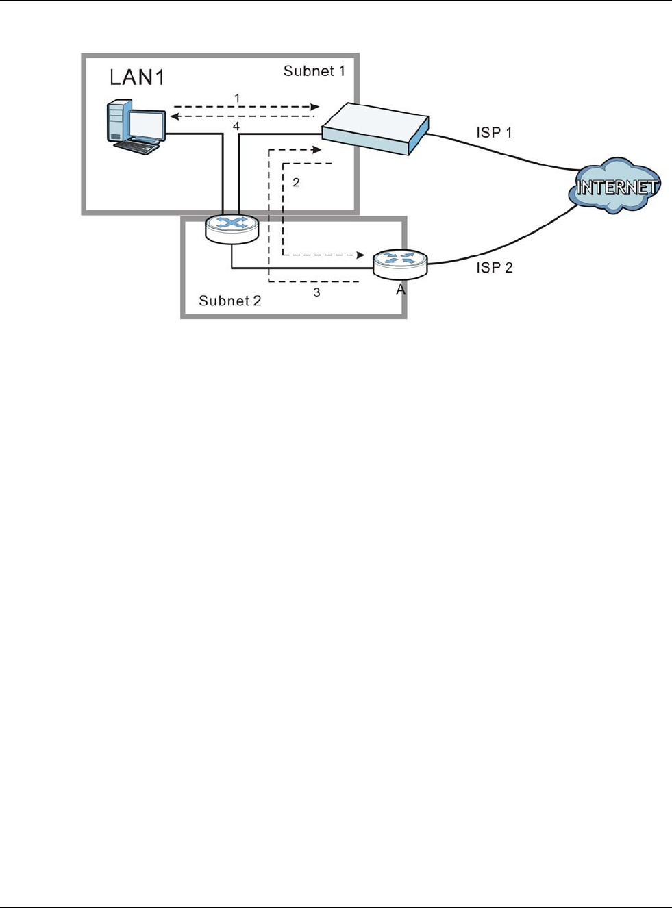
Chapter 20 Security Policy
USG20(W)-VPN Series User’s Guide
321
Figure 214 Using Virtual Interfaces to Avoid Asymmetrical Routes
20.4.1 Configuring the Security Policy Control Screen
Click Configuration > Security Policy > Policy Control to open the Security Policy screen.
Use this screen to enable or disable the Security Policy and asymmetrical routes, set a maximum
number of sessions per host, and display the configured Security Policies. Specify from which zone
packets come and to which zone packets travel to display only the policies specific to the selected
direction. Note the following.
• Besides configuring the Security Policy, you also need to configure NAT rules to allow computers
on the WAN to access LAN devices.
• The USG applies NAT (Destination NAT) settings before applying the Security Policies. So for
example, if you configure a NAT entry that sends WAN traffic to a LAN IP address, when you
configure a corresponding Security Policy to allow the traffic, you need to set the LAN IP address
as the destination.
• The ordering of your policies is very important as policies are applied in sequence.
The following screen shows the Security Policy summary screen.
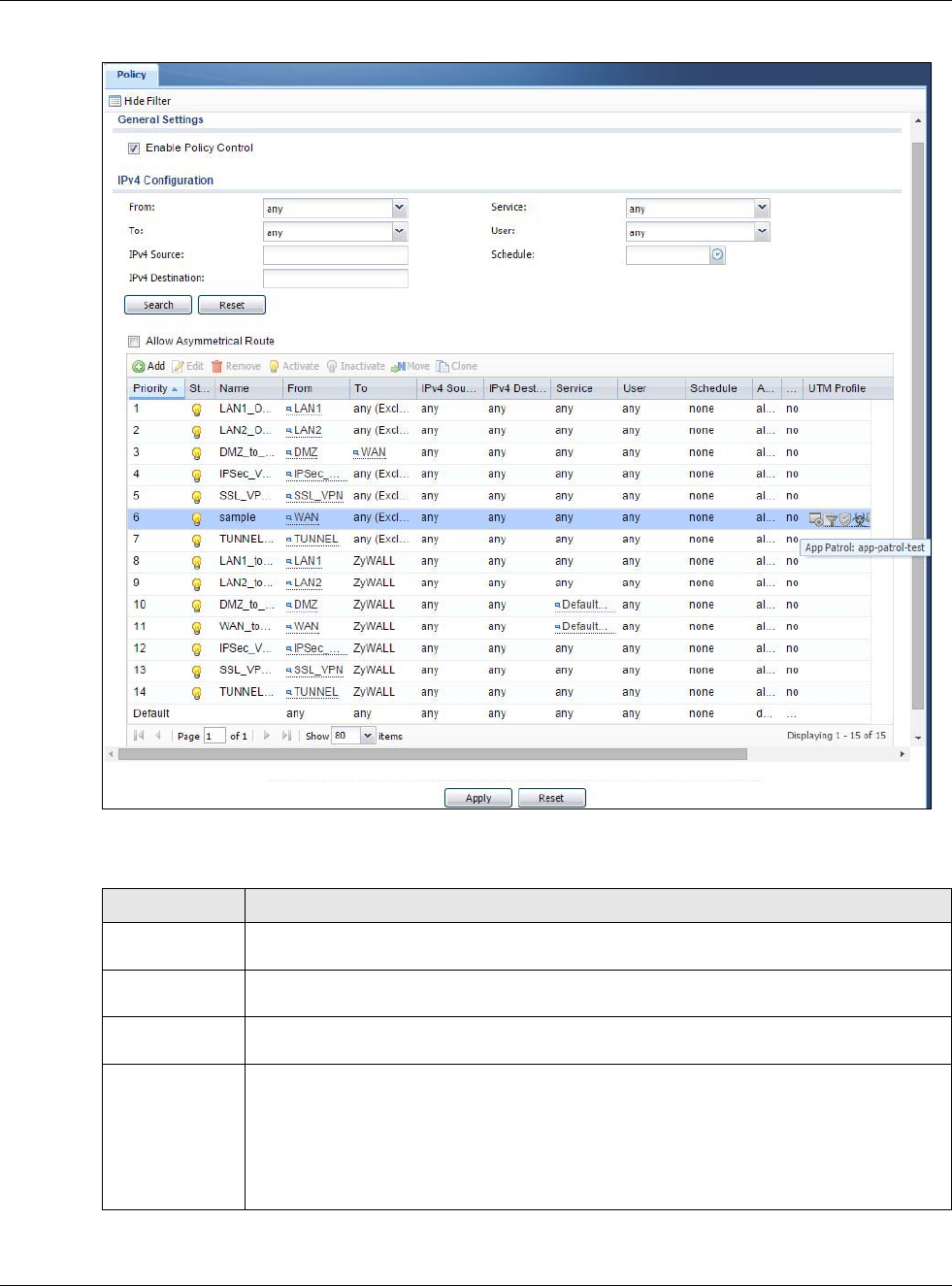
Chapter 20 Security Policy
USG20(W)-VPN Series User’s Guide
322
Figure 215 Configuration > Security Policy > Policy Control
The following table describes the labels in this screen.
Table 126 Configuration > Security Policy > Policy Control
LABEL DESCRIPTION
Show Filter/Hide
Filter
Click Show Filter to display IPv4 and IPv6 (if enabled) security policy search filters.
IPv4 / IPv6
Configuration
Use IPv4 / IPv6 search filters to find specific IPv4 and IPv6 (if enabled) security policies
based on direction, application, user, source, destination and/or schedule.
From / To Select a zone to view all security policies from a particular zone and/or to a particular zone.
any means all zones.
IPv4 / IPv6
Source Type an IPv4 or IPv6 IP address to view all security policies based on the IPv4 / IPv6
source address object used.
• An IPv4 IP address is written as four integer blocks separated by periods. This is an
example IPv4 address: 172.16.6.7.
• An 128-bit IPv6 address is written as eight 16-bit hexadecimal blocks separated by
colons (:). This is an example IPv6 address:
2001:0db8:1a2b:0015:0000:0000:1a2f:0000.

Chapter 20 Security Policy
USG20(W)-VPN Series User’s Guide
323
IPv4 / IPv6
Destination Type an IPv4 or IPv6 IP address to view all security policies based on the IPv4 / IPv6
destination address object used.
• An IPv4 IP address is written as four integer blocks separated by periods. This is an
example IPv4 address: 172.16.6.7.
• An 128-bit IPv6 address is written as eight 16-bit hexadecimal blocks separated by
colons (:). This is an example IPv6 address:
2001:0db8:1a2b:0015:0000:0000:1a2f:0000.
Service View all security policies based the service object used.
User View all security policies based on user or user group object used.
Schedule View all security policies based on the schedule object used.
General Settings Enable or disable the Security Policy feature on the USG.
Enable Policy
Control
Select this to activate Security Policy on the USG to perform access control.
IPv4/IPv6 Policy
Management
Use the following items to manage IPv4 and IPv6 policies.
Allow
Asymmetrica
l Route
If an alternate gateway on the LAN has an IP address in the same subnet as the USG’s LAN
IP address, return traffic may not go through the USG. This is called an asymmetrical or
“triangle” route. This causes the USG to reset the connection, as the connection has not
been acknowledged.
Select this check box to have the USG permit the use of asymmetrical route topology on
the network (not reset the connection).
Note: Allowing asymmetrical routes may let traffic from the WAN go directly to the LAN
without passing through the USG. A better solution is to use virtual interfaces to put
the USG and the backup gateway on separate subnets.
Add Click this to create a new entry. Select an entry and click Add to create a new entry after
the selected entry.
Edit Double-click an entry or select it and click Edit to open a screen where you can modify the
entry’s settings.
Remove To remove an entry, select it and click Remove. The USG confirms you want to remove it
before doing so.
Activate To turn on an entry, select it and click Activate.
Inactivate To turn off an entry, select it and click Inactivate.
Move To change a policy’s position in the numbered list, select the policy and click Move to
display a field to type a number for where you want to put that policy and press [ENTER] to
move the policy to the number that you typed.
The ordering of your policies is important as they are applied in order of their numbering.
Clone Use Clone to create a new entry by modifying an existing one.
• Select an existing entry.
•Click Clone, type a number where the new entry should go and then press [ENTER].
• A configuration copy of the selected entry pops up. You must at least change the name
as duplicate entry names are not allowed.
The following read-only fields summarize the policies you have created that apply to traffic traveling in the
selected packet direction.
Priority This is the position of your Security Policy in the global policy list (including all through-
USG and to-USG policies). The ordering of your policies is important as policies are applied
in sequence. Default displays for the default Security Policy behavior that the USG
performs on traffic that does not match any other Security Policy.
Status This icon is lit when the entry is active and dimmed when the entry is inactive.
Table 126 Configuration > Security Policy > Policy Control (continued)
LABEL DESCRIPTION
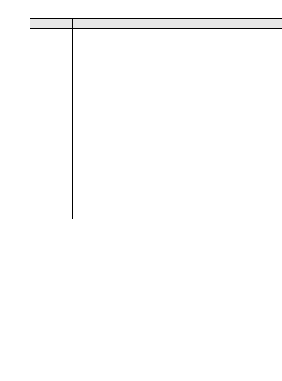
Chapter 20 Security Policy
USG20(W)-VPN Series User’s Guide
324
20.4.2 The Security Policy Control Add/Edit Screen
In the Security Policy Control screen, click the Edit or Add icon to display the Security Policy
Edit or Add screen.
Name This is the name of the Security policy.
From / To This is the direction of travel of packets. Select from which zone the packets come and to
which zone they go.
Security Policies Rare grouped based on the direction of travel of packets to which they
apply. For example, from LAN to LAN means packets traveling from a computer or subnet
on the LAN to either another computer or subnet on the LAN.
From any displays all the Security Policies for traffic going to the selected To Zone.
To any displays all the Security Policies for traffic coming from the selected From Zone.
From any to any displays all of the Security Policies.
To ZyWALL policies are for traffic that is destined for the USG and control which computers
can manage the USG.
IPv4 / IPv6
Source
This displays the IPv4 / IPv6 source address object to which this Security Policy applies.
IPv4 / IPv6
Destination
This displays the IPv4 / IPv6 destination address object to which this Security Policy
applies.
Service This displays the service object to which this Security Policy applies.
User This is the user name or user group name to which this Security Policy applies.
Schedule This field tells you the schedule object that the policy uses. none means the policy is active
at all times if enabled.
Action This field displays whether the Security Policy silently discards packets without notification
(deny), permits the passage of packets (allow) or drops packets with notification (reject)
UTM Profile This field shows you which UTM profiles (content filter, anti-spam) apply to this Security
policy. Click an applied UTM profile icon to edit the profile directly.
Apply Click Apply to save your changes back to the USG.
Reset Click Reset to return the screen to its last-saved settings.
Table 126 Configuration > Security Policy > Policy Control (continued)
LABEL DESCRIPTION
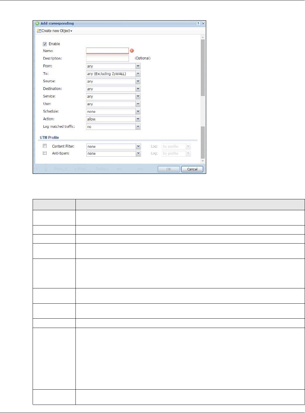
Chapter 20 Security Policy
USG20(W)-VPN Series User’s Guide
325
Figure 216 Configuration > Security Policy > Policy Control > Add
The following table describes the labels in this screen.
Table 127 Configuration > Security Policy > Policy Control > Add
LABEL DESCRIPTION
Create new
Object
Use to configure any new settings objects that you need to use in this screen.
Enable Select this check box to activate the Security policy.
Name Type a name to identify the policy
Description Enter a descriptive name of up to 60 printable ASCII characters for the Policy. Spaces are
allowed.
From
To
For through-USG policies, select the direction of travel of packets to which the policy applies.
any means all interfaces.
Device means packets destined for the USG itself.
Source Select an IPv4 / IPv6 address or address group object to apply the policy to traffic coming
from it. Select any to apply the policy to all traffic coming from IPv4 / IPv6 addresses.
Destination Select an IPv4 / IPv6 address or address group to apply the policy to traffic going to it.
Select any to apply the policy to all traffic going to IPv4 / IPv6 addresses.
Service Select a service or service group from the drop-down list box.
User This field is not available when you are configuring a to-USG policy.
Select a user name or user group to which to apply the policy. The Security Policy is
activated only when the specified user logs into the system and the policy will be disabled
when the user logs out.
Otherwise, select any and there is no need for user logging.
Note: If you specified a source IP address (group) instead of any in the field below, the user’s
IP address should be within the IP address range.
Schedule Select a schedule that defines when the policy applies. Otherwise, select none and the
policy is always effective.
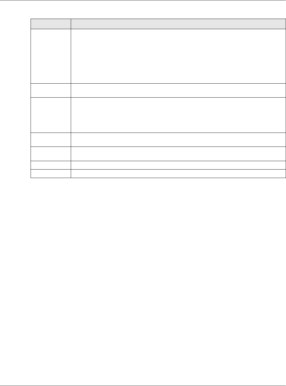
Chapter 20 Security Policy
USG20(W)-VPN Series User’s Guide
326
20.5 The Session Control Screen
Click Configuration > Security Policy > Session Control to display the Security Policy
Session Control screen. Use this screen to limit the number of concurrent NAT/Security Policy
sessions a client can use. You can apply a default limit for all users and individual limits for specific
users, addresses, or both. The individual limit takes priority if you apply both.
Action Use the drop-down list box to select what the Security Policy is to do with packets that
match this policy.
Select deny to silently discard the packets without sending a TCP reset packet or an ICMP
destination-unreachable message to the sender.
Select reject to discard the packets and send a TCP reset packet or an ICMP destination-
unreachable message to the sender.
Select allow to permit the passage of the packets.
Log matched
traffic
Select whether to have the USG generate a log (log), log and alert (log alert) or not (no)
when the policy is matched to the criteria listed above..
UTM Profile Use this section to apply anti- x profiles (created in the Configuration > UTM Profile
screens) to traffic that matches the criteria above. You must have created a profile first;
otherwise none displays.
Use Log to generate a log (log), log and alert (log alert) or not (no) for all traffic that
matches criteria in the profile.
Content
Filter Select a Content Filter profile from the list box; none displays if no profiles have been
created in the Configuration > UTM Profile > Content Filter screen.
Anti-Spam Select an Anti-Spam profile from the list box; none displays if no profiles have been created
in the Configuration > UTM Profile > Anti-Spam screen.
OK Click OK to save your customized settings and exit this screen.
Cancel Click Cancel to exit this screen without saving.
Table 127 Configuration > Security Policy > Policy Control > Add (continued)
LABEL DESCRIPTION
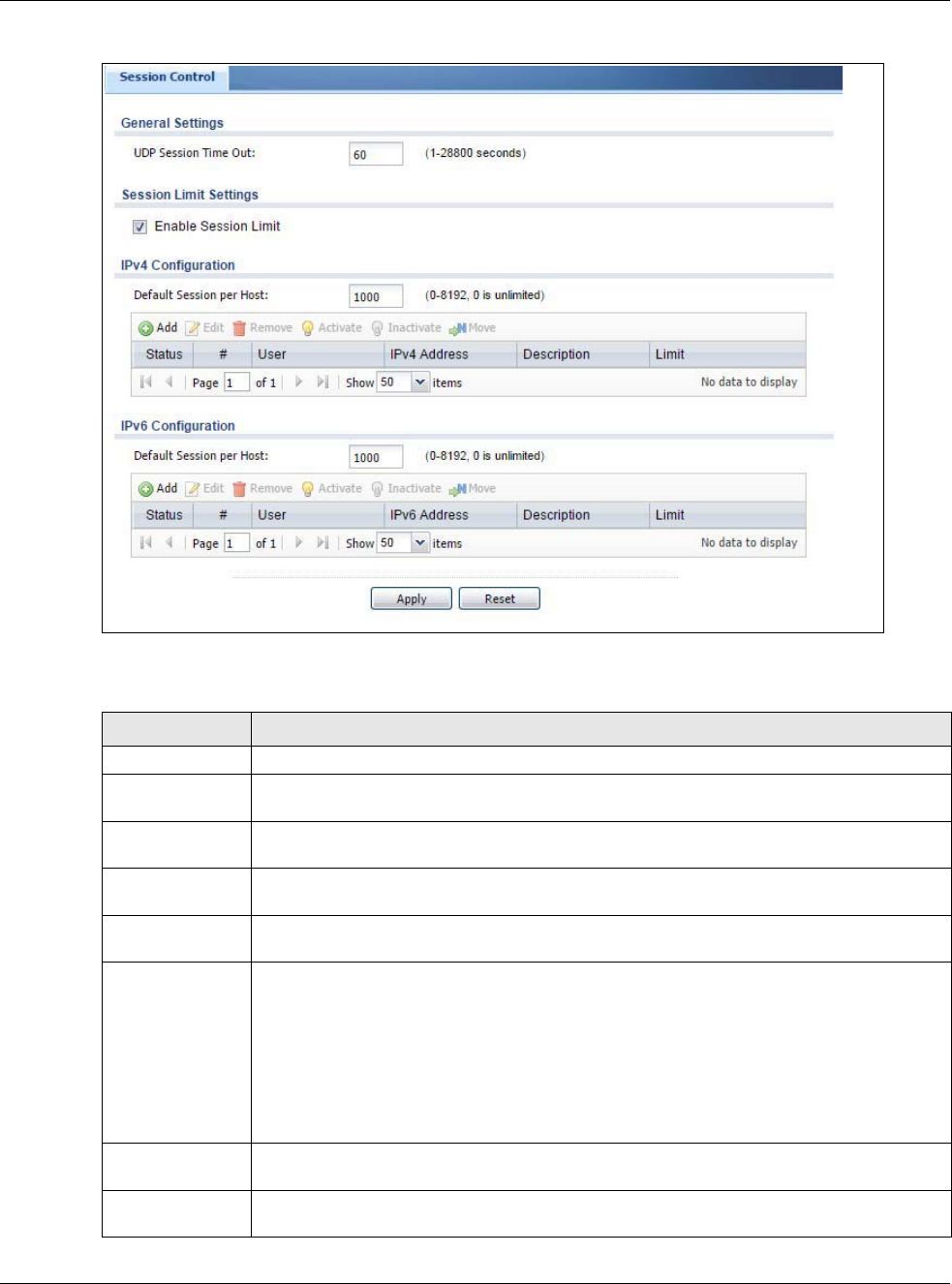
Chapter 20 Security Policy
USG20(W)-VPN Series User’s Guide
327
Figure 217 Configuration > Security Policy > Session Control
The following table describes the labels in this screen.
Table 128 Configuration > Security Policy > Session Control
LABEL DESCRIPTION
General Settings
UDP Session
Time Out
Set how many seconds the USG will allow a UDP session to remain idle (without UDP
traffic) before closing it.
Session Limit
Settings
Enable Session
limit
Select this check box to control the number of concurrent sessions hosts can have.
IPv4 / IPv6 Rule
Summary
This table lists the rules for limiting the number of concurrent sessions hosts can have.
Default
Session per
Host
This field is configurable only when you enable session limit.
Use this field to set a common limit to the number of concurrent NAT/Security Policy
sessions each client computer can have.
If only a few clients use peer to peer applications, you can raise this number to improve
their performance. With heavy peer to peer application use, lower this number to ensure
no single client uses too many of the available NAT sessions.
Create rules below to apply other limits for specific users or addresses.
Add Click this to create a new entry. Select an entry and click Add to create a new entry after
the selected entry.
Edit Double-click an entry or select it and click Edit to open a screen where you can modify the
entry’s settings.
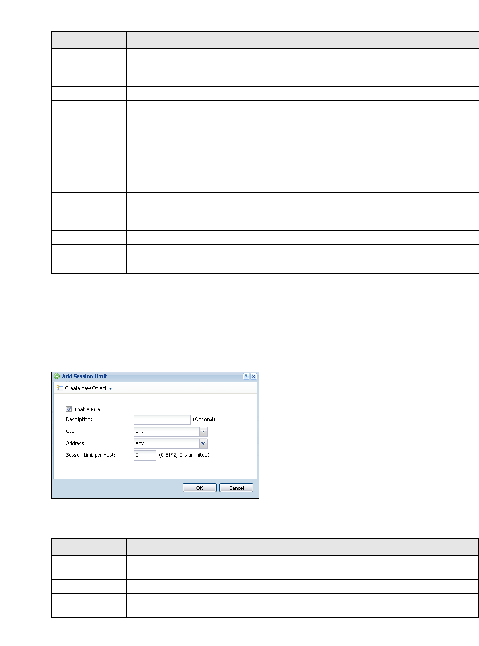
Chapter 20 Security Policy
USG20(W)-VPN Series User’s Guide
328
20.5.1 The Session Control Add/Edit Screen
Click Configuration > Security Policy > Session Control and the Add or Edit icon to display
the Add or Edit screen. Use this screen to configure rules that define a session limit for specific
users or addresses.
Figure 218 Configuration > Security Policy > Session Control > Edit
The following table describes the labels in this screen.
Remove To remove an entry, select it and click Remove. The USG confirms you want to remove it
before doing so.
Activate To turn on an entry, select it and click Activate.
Inactivate To turn off an entry, select it and click Inactivate.
Move To change a rule’s position in the numbered list, select the rule and click Move to display a
field to type a number for where you want to put that rule and press [ENTER] to move the
rule to the number that you typed.
The ordering of your rules is important as they are applied in order of their numbering.
Status This icon is lit when the entry is active and dimmed when the entry is inactive.
# This is the index number of a session limit rule. It is not associated with a specific rule.
User This is the user name or user group name to which this session limit rule applies.
IPv4 / IPv6
Address
This is the IPv4 / IPv6 address object to which this session limit rule applies.
Description This is the information configured to help you identify the rule.
Limit This is how many concurrent sessions this user or address is allowed to have.
Apply Click Apply to save your changes back to the USG.
Reset Click Reset to return the screen to its last-saved settings.
Table 128 Configuration > Security Policy > Session Control (continued)
LABEL DESCRIPTION
Table 129 Configuration > Security Policy > Session Control > Add / Edit
LABEL DESCRIPTION
Create new
Object
Use to configure new settings for User or Address objects that you need to use in this
screen.Click on the down arrow to see the menu.
Enable Rule Select this check box to turn on this session limit rule.
Description Enter information to help you identify this rule. Use up to 60 printable ASCII characters.
Spaces are allowed.
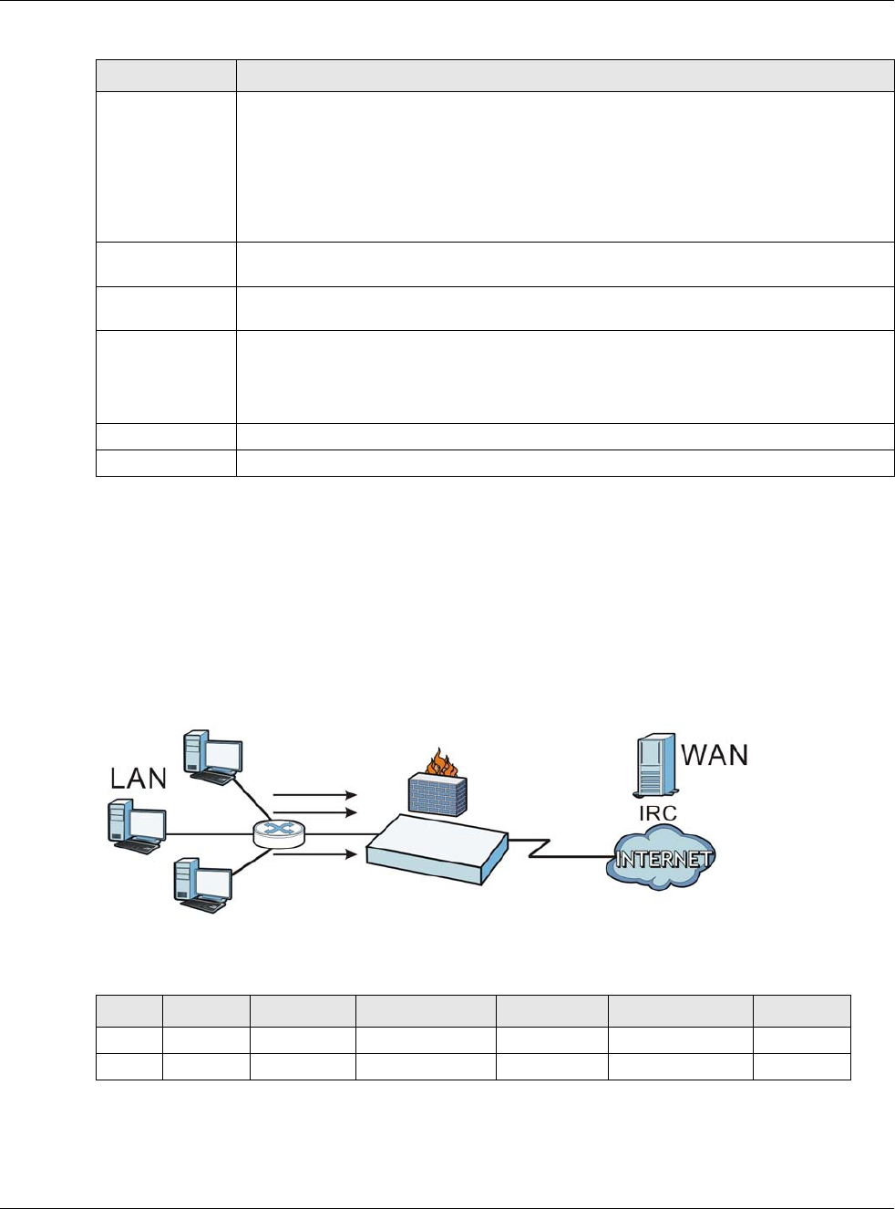
Chapter 20 Security Policy
USG20(W)-VPN Series User’s Guide
329
20.6 Security Policy Example Applications
Suppose you decide to block LAN users from using IRC (Internet Relay Chat) through the Internet.
To do this, you would configure a LAN to WAN Security Policy that blocks IRC traffic from any source
IP address from going to any destination address. You do not need to specify a schedule since you
need the Security Policy to always be in effect. The following figure shows the results of this policy.
Figure 219 Blocking All LAN to WAN IRC Traffic Example
Your Security Policy would have the following settings.
• The first row blocks LAN access to the IRC service on the WAN.
• The second row is the Security Policy’s default policy that allows all LAN1 to WAN traffic.
User Select a user name or user group to which to apply the rule. The rule is activated only
when the specified user logs into the system and the rule will be disabled when the user
logs out.
Otherwise, select any and there is no need for user logging.
Note: If you specified an IP address (or address group) instead of any in the field below, the
user’s IP address should be within the IP address range.
Address Select the IPv4 source address or address group to which this rule applies. Select any to
apply the rule to all IPv4 source addresses.
IPv6 Address Select the IPv6 source address or address group to which this rule applies. Select any to
apply the rule to all IPv6 source addresses.
Session Limit per
Host
Use this field to set a limit to the number of concurrent NAT/Security Policy sessions this
rule’s users or addresses can have.
For this rule’s users and addresses, this setting overrides the Default Session per Host
setting in the general Security Policy Session Control screen.
OK Click OK to save your customized settings and exit this screen.
Cancel Click Cancel to exit this screen without saving.
Table 129 Configuration > Security Policy > Session Control > Add / Edit (continued)
LABEL DESCRIPTION
Table 130 Blocking All LAN to WAN IRC Traffic Example
#USER SOURCE DESTINATION SCHEDULE UTM PROFILE ACTION
1 Any Any Any Any IRC Deny
2 Any Any Any Any Any Allow
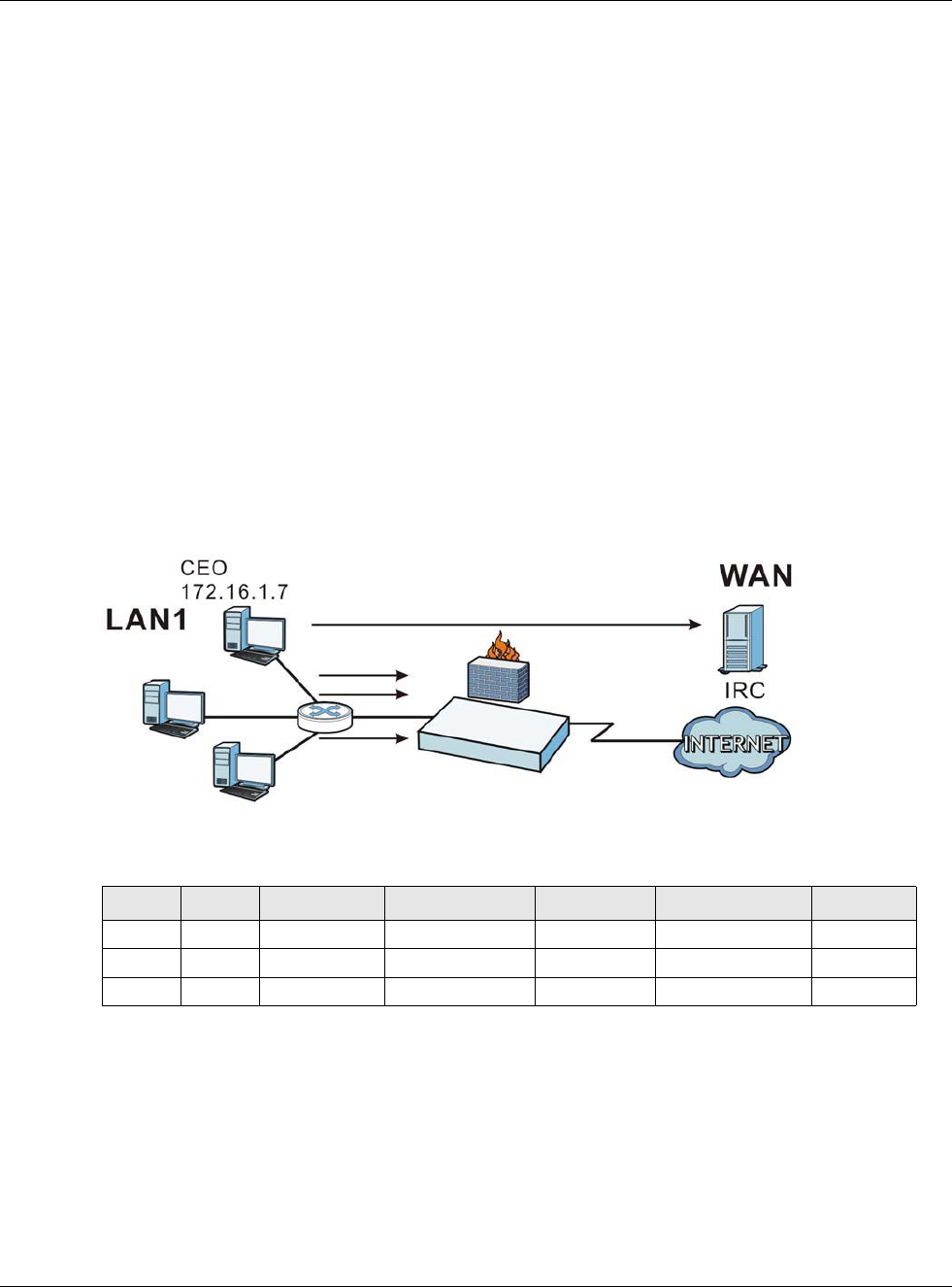
Chapter 20 Security Policy
USG20(W)-VPN Series User’s Guide
330
The USG applies the security policies in order. So for this example, when the USG receives traffic
from the LAN, it checks it against the first policy. If the traffic matches (if it is IRC traffic) the
security policy takes the action in the policy (drop) and stops checking the subsequent security
policies. Any traffic that does not match the first security policy will match the second security
policy and the USG forwards it.
Now suppose you need to let the CEO use IRC. You configure a LAN1 to WAN security policy that
allows IRC traffic from the IP address of the CEO’s computer. You can also configure a LAN to WAN
policy that allows IRC traffic from any computer through which the CEO logs into the USG with his/
her user name. In order to make sure that the CEO’s computer always uses the same IP address,
make sure it either:
• Has a static IP address,
or
• You configure a static DHCP entry for it so the USG always assigns it the same IP address.
Now you configure a LAN1 to WAN security policy that allows IRC traffic from the IP address of the
CEO’s computer (172.16.1.7 for example) to go to any destination address. You do not need to
specify a schedule since you want the security policy to always be in effect. The following figure
shows the results of your two custom policies.
Figure 220 Limited LAN to WAN IRC Traffic Example
Your security policy would have the following configuration.
• The first row allows the LAN1 computer at IP address 172.16.1.7 to access the IRC service on the
WAN.
• The second row blocks LAN1 access to the IRC service on the WAN.
• The third row is the default policy of allowing all traffic from the LAN1 to go to the WAN.
Alternatively, you configure a LAN1 to WAN policy with the CEO’s user name (say CEO) to allow IRC
traffic from any source IP address to go to any destination address.
Table 131 Limited LAN1 to WAN IRC Traffic Example 1
#USER SOURCE DESTINATION SCHEDULE UTM PROFILE ACTION
1 Any 172.16.1.7 Any Any IRC Allow
2 Any Any Any Any IRC Deny
3 Any Any Any Any Any Allow

Chapter 20 Security Policy
USG20(W)-VPN Series User’s Guide
331
Your Security Policy would have the following settings.
• The first row allows any LAN1 computer to access the IRC service on the WAN by logging into the
USG with the CEO’s user name.
• The second row blocks LAN1 access to the IRC service on the WAN.
• The third row is the default policy of allowing allows all traffic from the LAN1 to go to the WAN.
The policy for the CEO must come before the policy that blocks all LAN1 to WAN IRC traffic. If the
policy that blocks all LAN1 to WAN IRC traffic came first, the CEO’s IRC traffic would match that
policy and the USG would drop it and not check any other security policies.
Table 132 Limited LAN1 to WAN IRC Traffic Example 2
#USER SOURCE DESTINATION SCHEDULE UTM PROFILE ACTION
1 CEO Any Any Any IRC Allow
2 Any Any Any Any IRC Deny
3 Any Any Any Any Any Allow
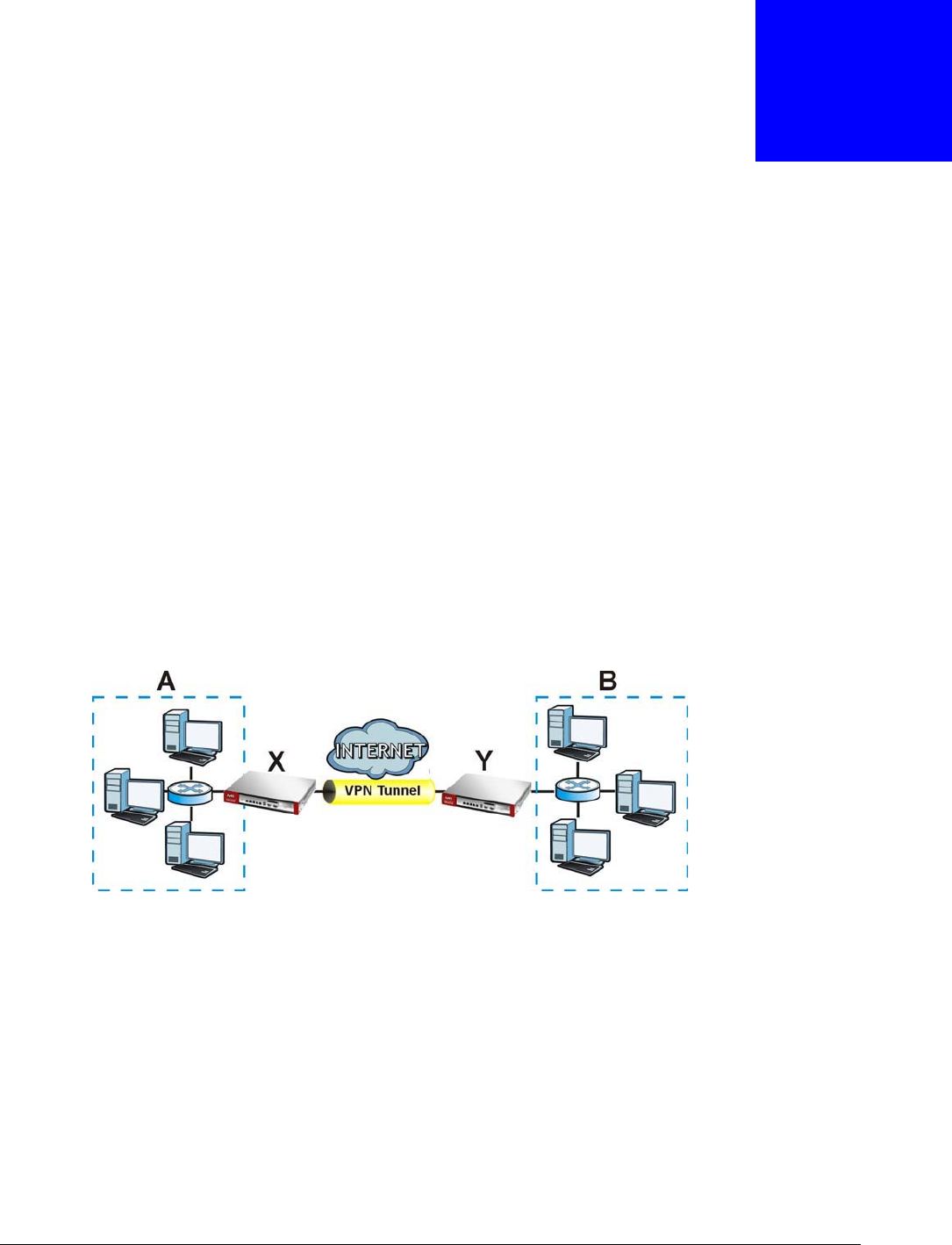
USG20(W)-VPN Series User’s Guide
332
CHAPTER 21
IPSec VPN
21.1 Virtual Private Networks (VPN) Overview
A virtual private network (VPN) provides secure communications between sites without the expense
of leased site-to-site lines. A secure VPN is a combination of tunneling, encryption, authentication,
access control and auditing. It is used to transport traffic over the Internet or any insecure network
that uses TCP/IP for communication.
IPSec VPN
Internet Protocol Security (IPSec) VPN connects IPSec routers or remote users using IPSec client
software. This standards-based VPN offers flexible solutions for secure data communications across
a public network. IPSec is built around a number of standardized cryptographic techniques to
provide confidentiality, data integrity and authentication at the IP layer. The USG can also combine
multiple IPSec VPN connections into one secure network. Here local USG X uses an IPSec VPN
tunnel to remote (peer) USG Y to connect the local (A) and remote (B) networks.
Figure 221 IPSec VPN Example
Internet Key Exchange (IKE): IKEv1 and IKEv2
The USG supports IKEv1 and IKEv2 for IPv4 and IPv6 traffic. IKE (Internet Key Exchange) is a
protocol used in setting up security associations that allows two parties to send data securely.
IKE uses certificates or pre-shared keys for authentication and a Diffie–Hellman key exchange to
set up a shared session secret from which encryption keys are derived. A security policy for each
peer must be manually created.
IPSec VPN consists of two phases: Phase 1 and Phase 2. Phase 1's purpose is to establish a secure
authenticated communication channel by using the Diffie–Hellman key exchange algorithm to
generate a shared secret key to encrypt IKE communications. This negotiation results in one single
bi-directional ISAKMP Security Association (SA). The authentication can be performed using either
pre-shared key (shared secret), signatures, or public key encryption. Phase 1 operates in either

Chapter 21 IPSec VPN
USG20(W)-VPN Series User’s Guide
333
Main Mode or Aggressive Mode. Main Mode protects the identity of the peers, but Aggressive
Mode does not.
During Phase 2, the remote IPSec routers use the secure channel established in Phase 1 to
negotiate Security Associations for IPsec. The negotiation results in a minimum of two
unidirectional security associations (one inbound and one outbound). Phase 2 uses Quick Mode
(only). Quick mode occurs after IKE has established the secure tunnel in Phase 1. It negotiates a
shared IPSec policy, derives shared secret keys used for the IPSec security algorithms, and
establishes IPSec SAs. Quick mode is also used to renegotiate a new IPSec SA when the IPSec SA
lifetime expires.
In the USG, use the VPN Connection tab to set up Phase 2 and the VPN Gateway tab to set up
Phase 1.
Some differences between IKEv1 and IKEv2 include:
• IKEv2 uses less bandwidth than IKEv1. IKEv2 uses one exchange procedure with 4 messages.
IKEv1 uses two phases with Main Mode (9 messages) or Aggressive Mode (6 messages) in phase
1.
• IKEv2 supports Extended Authentication Protocol (EAP) authentication, and IKEv1 supports X-
Auth. EAP is important when connecting to existing enterprise authentication systems.
• IKEv2 always uses NAT traversal and Dead Peer Detection (DPD), but they can be disabled in
IKEv1 using USG firmware (the default is on).
• Configuration payload (includes the IP address pool in the VPN setup data) is supported in IKEv2
(off by default), but not in IKEv1.
• Narrowed (has the SA apply only to IP addresses in common between the USG and the remote
IPSec router) is supported in IKEv2, but not in IKEv1.
• The IKEv2 protocol supports connectivity checks which is used to detect whether the tunnel is
still up or not. If the check fails (the tunnel is down), IKEv2 can re-establish the connection
automatically. The USG uses firmware to perform connectivity checks when using IKEv1.
SSL VPN
SSL VPN uses remote users’ web browsers to provide the easiest-to-use of the USG’s VPN solutions.
A user just browses to the USG’s web address and enters his user name and password to securely
connect to the USG’s network. Remote users do not need to configure security settings. Here a user
uses his browser to securely connect to network resources in the same way as if he were part of the
internal network. See Chapter 22 on page 367 for more on SSL VPN.
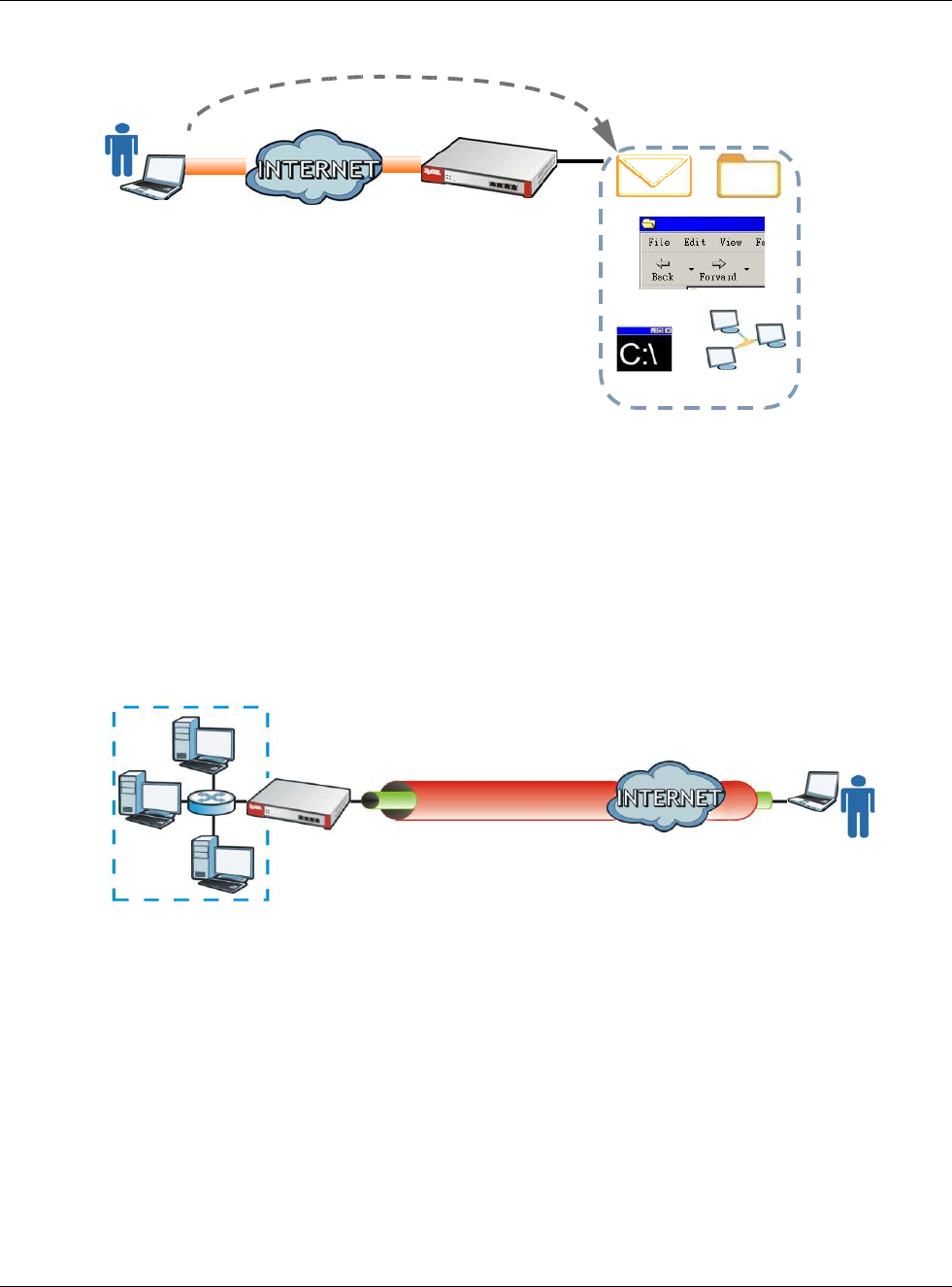
Chapter 21 IPSec VPN
USG20(W)-VPN Series User’s Guide
334
Figure 222 SSL VPN
L2TP VPN
L2TP VPN uses the L2TP and IPSec client software included in remote users’ Android, iOS, or
Windows operating systems for secure connections to the network behind the USG. The remote
users do not need their own IPSec gateways or third-party VPN client software. For example,
configure sales representatives’ laptops, tablets, or smartphones to securely connect to the USG’s
network. See Chapter 25 on page 395 for more on L2TP over IPSec.
Figure 223 L2TP VPN
21.1.1 What You Can Do in this Chapter
•Use the VPN Connection screens (see Section 21.2 on page 337) to specify which IPSec VPN
gateway an IPSec VPN connection policy uses, which devices behind the IPSec routers can use
the VPN tunnel, and the IPSec SA settings (phase 2 settings). You can also activate or deactivate
and connect or disconnect each VPN connection (each IPSec SA).
•Use the VPN Gateway screens (see Section 21.2.1 on page 338) to manage the USG’s VPN
gateways. A VPN gateway specifies the IPSec routers at either end of a VPN tunnel and the IKE
SA settings (phase 1 settings). You can also activate and deactivate each VPN gateway.
•Use the VPN Concentrator screens (see Section 21.4 on page 353) to combine several IPSec
VPN connections into a single secure network.
•Use the Configuration Provisioning screen (see Section 21.5 on page 355) to set who can
retrieve VPN rule settings from the USG using the USG IPSec VPN Client.
Web Mail File Share
Web-based Application
https://
Application
Server
Non-Web
LAN (192.168.1.X)
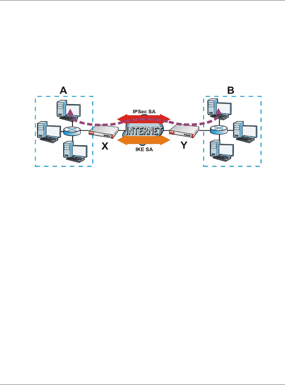
Chapter 21 IPSec VPN
USG20(W)-VPN Series User’s Guide
335
21.1.2 What You Need to Know
An IPSec VPN tunnel is usually established in two phases. Each phase establishes a security
association (SA), a contract indicating what security parameters the USG and the remote IPSec
router will use. The first phase establishes an Internet Key Exchange (IKE) SA between the USG
and remote IPSec router. The second phase uses the IKE SA to securely establish an IPSec SA
through which the USG and remote IPSec router can send data between computers on the local
network and remote network. This is illustrated in the following figure.
Figure 224 VPN: IKE SA and IPSec SA
In this example, a computer in network A is exchanging data with a computer in network B. Inside
networks A and B, the data is transmitted the same way data is normally transmitted in the
networks. Between routers X and Y, the data is protected by tunneling, encryption, authentication,
and other security features of the IPSec SA. The IPSec SA is secure because routers X and Y
established the IKE SA first.
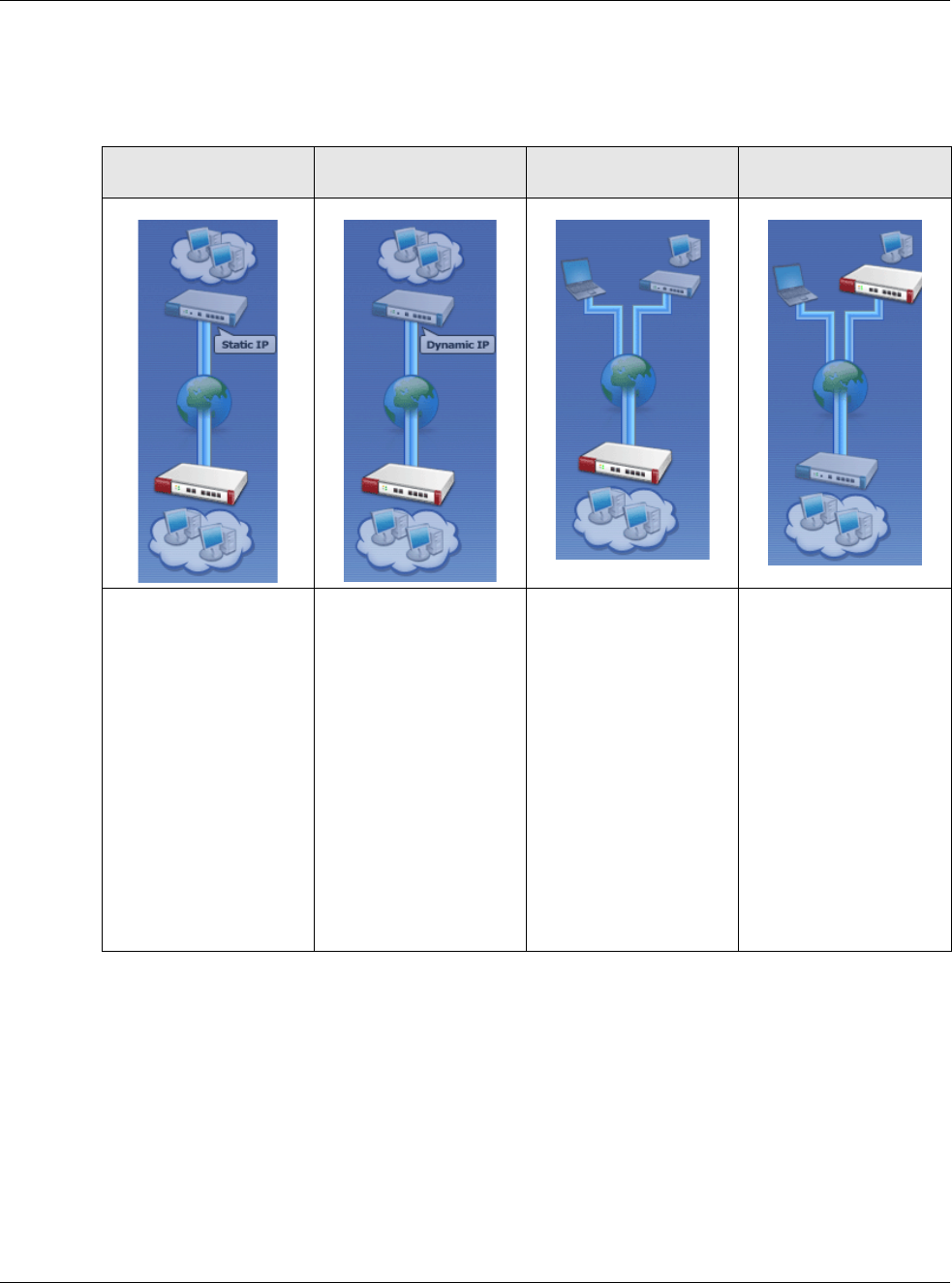
Chapter 21 IPSec VPN
USG20(W)-VPN Series User’s Guide
336
Application Scenarios
The USG’s application scenarios make it easier to configure your VPN connection settings.
Finding Out More
•See Section 21.6 on page 357 for IPSec VPN background information.
• See the help in the IPSec VPN quick setup wizard screens.
21.1.3 Before You Begin
This section briefly explains the relationship between VPN tunnels and other features. It also gives
some basic suggestions for troubleshooting.
You should set up the following features before you set up the VPN tunnel.
Table 133 IPSec VPN Application Scenarios
SITE-TO-SITE SITE-TO-SITE WITH
DYNAMIC PEER REMOTE ACCESS
(SERVER ROLE) REMOTE ACCESS
(CLIENT ROLE)
Choose this if the remote
IPSec router has a static
IP address or a domain
name.
This USG can initiate the
VPN tunnel.
The remote IPSec router
can also initiate the VPN
tunnel if this USG has a
static IP address or a
domain name.
Choose this if the remote
IPSec router has a
dynamic IP address.
You don’t specify the
remote IPSec router’s
address, but you specify
the remote policy (the
addresses of the devices
behind the remote IPSec
router).
This USG must have a
static IP address or a
domain name.
Only the remote IPSec
router can initiate the
VPN tunnel.
Choose this to allow
incoming connections
from IPSec VPN clients.
The clients have dynamic
IP addresses and are also
known as dial-in users.
You don’t specify the
addresses of the client
IPSec routers or the
remote policy.
This creates a dynamic
IPSec VPN rule that can
let multiple clients
connect.
Only the clients can
initiate the VPN tunnel.
Choose this to connect to
an IPSec server.
This USG is the client
(dial-in user).
Client role USGs initiate
IPSec VPN connections to
a server role USG.
This USG can have a
dynamic IP address.
The IPSec server doesn’t
configure this USG’s IP
address or the addresses
of the devices behind it.
Only this USG can initiate
the VPN tunnel.

Chapter 21 IPSec VPN
USG20(W)-VPN Series User’s Guide
337
• In any VPN connection, you have to select address objects to specify the local policy and remote
policy. You should set up the address objects first.
• In a VPN gateway, you can select an Ethernet interface, virtual Ethernet interface, VLAN
interface, or virtual VLAN interface to specify what address the USG uses as its IP address when
it establishes the IKE SA. You should set up the interface first.
• In a VPN gateway, you can enable extended authentication. If the USG is in server mode, you
should set up the authentication method (AAA server) first. The authentication method specifies
how the USG authenticates the remote IPSec router.
• In a VPN gateway, the USG and remote IPSec router can use certificates to authenticate each
other. Make sure the USG and the remote IPSec router will trust each other’s certificates.
21.2 The VPN Connection Screen
Click Configuration > VPN > IPSec VPN to open the VPN Connection screen. The VPN
Connection screen lists the VPN connection policies and their associated VPN gateway(s), and
various settings. In addition, it also lets you activate or deactivate and connect or disconnect each
VPN connection (each IPSec SA). Click a column’s heading cell to sort the table entries by that
column’s criteria. Click the heading cell again to reverse the sort order.
Click on the icons to go to the OneSecurity.com website where there is guidance on configuration
walkthroughs, troubleshooting and other information.
Figure 225 Configuration > VPN > IPSec VPN > VPN Connection

Chapter 21 IPSec VPN
USG20(W)-VPN Series User’s Guide
338
Each field is discussed in the following table.
21.2.1 The VPN Connection Add/Edit (IKE) Screen
The VPN Connection Add/Edit Gateway screen allows you to create a new VPN connection
policy or edit an existing one. To access this screen, go to the Configuration > VPN Connection
screen (see Section 21.2 on page 337), and click either the Add icon or an Edit icon.
Table 134 Configuration > VPN > IPSec VPN > VPN Connection
LABEL DESCRIPTION
Global Setting The following two fields are for all IPSec VPN policies.
Click on the VPN icon to go to the ZyXEL VPN Client product page at the ZyXEL website.
Use Policy
Route to
control
dynamic
IPSec rules
Select this to be able to use policy routes to manually specify the destination addresses of
dynamic IPSec rules. You must manually create these policy routes. The USG automatically
obtains source and destination addresses for dynamic IPSec rules that do not match any of
the policy routes.
Clear this to have the USG automatically obtain source and destination addresses for all
dynamic IPSec rules.
Ignore
"Don't
Fragment"
setting in
packet
header
Select this to fragment packets larger than the MTU (Maximum Transmission Unit) that have
the "Don't Fragment" bit in the IP header turned on. When you clear this the USG drops
packets larger than the MTU that have the "Don't Fragment" bit in the header turned on.
IPv4 / IPv6
Configuration
Add Click this to create a new entry.
Edit Double-click an entry or select it and click Edit to open a screen where you can modify the
entry’s settings.
Remove To remove an entry, select it and click Remove. The USG confirms you want to remove it
before doing so.
Activate To turn on an entry, select it and click Activate.
Inactivate To turn off an entry, select it and click Inactivate.
Connect To connect an IPSec SA, select it and click Connect.
Disconnect To disconnect an IPSec SA, select it and click Disconnect.
Object
Reference
Select an entry and click Object Reference to open a screen that shows which settings use
the entry. See Section 9.3.2 on page 163 for an example.
# This field is a sequential value, and it is not associated with a specific connection.
Status The activate (light bulb) icon is lit when the entry is active and dimmed when the entry is
inactive.
The connect icon is lit when the interface is connected and dimmed when it is disconnected.
Name This field displays the name of the IPSec SA.
VPN Gateway This field displays the VPN gateway in use for this VPN connection.
Gateway IP
Version
This field displays what IP version the associated VPN gateway(s) is using. An IPv4 gateway
may use an IKEv1 or IKEv2 SA. An IPv6 gateway may use IKEv2 only.
Policy This field displays the local policy and the remote policy, respectively.
Apply Click Apply to save your changes back to the USG.
Reset Click Reset to return the screen to its last-saved settings.
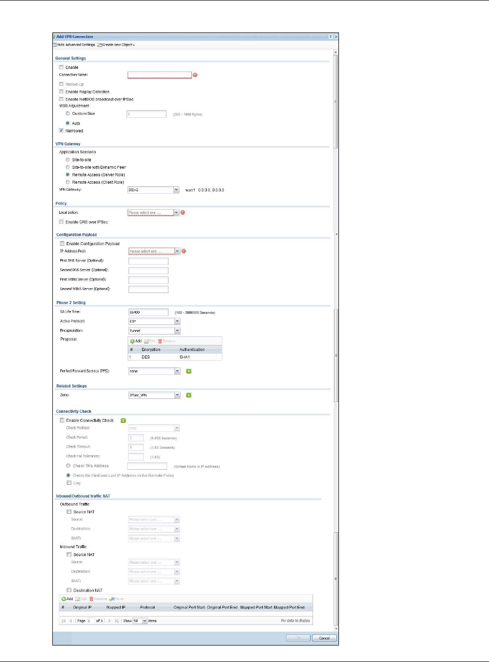
Chapter 21 IPSec VPN
USG20(W)-VPN Series User’s Guide
339
Figure 226 Configuration > VPN > IPSec VPN > VPN Connection > Edit (IKE)

Chapter 21 IPSec VPN
USG20(W)-VPN Series User’s Guide
340
Each field is described in the following table.
Table 135 Configuration > VPN > IPSec VPN > VPN Connection > Edit
LABEL DESCRIPTION
Show Advanced
Settings / Hide
Advanced Settings
Click this button to display a greater or lesser number of configuration fields.
Create new Object Use to configure any new settings objects that you need to use in this screen.
General Settings
Enable Select this check box to activate this VPN connection.
Connection Name Type the name used to identify this IPSec SA. You may use 1-31 alphanumeric
characters, underscores (_), or dashes (-), but the first character cannot be a
number. This value is case-sensitive.
Nailed-Up Select this if you want the USG to automatically renegotiate the IPSec SA when the
SA life time expires.
Enable Replay
Detection Select this check box to detect and reject old or duplicate packets to protect against
Denial-of-Service attacks.
Enable NetBIOS
Broadcast over
IPSec
Select this check box if you the USG to send NetBIOS (Network Basic Input/Output
System) packets through the IPSec SA.
NetBIOS packets are TCP or UDP packets that enable a computer to connect to and
communicate with a LAN. It may sometimes be necessary to allow NetBIOS packets
to pass through IPSec SAs in order to allow local computers to find computers on the
remote network and vice versa.
MSS Adjustment Select Custom Size to set a specific number of bytes for the Maximum Segment Size
(MSS) meaning the largest amount of data in a single TCP segment or IP datagram
for this VPN connection.
Some VPN clients may not be able to use a custom MSS size if it is set too small. In
that case those VPN clients will ignore the size set here and use the minimum size
that they can use.
Select Auto to have the USG automatically set the MSS for this VPN connection.
Narrowed If the IP range on the USG (local policy) and the local IP range on the remote IPSec
router overlap in an IKEv2 SA, then you may select Narrowed to have the SA only
apply to the IP addresses in common.
Here are some examples.
USG (local policy) Remote IPSec router
IKEv2 SA-1 192.168.20.0/24 192.168.20.1 ~ 192.168.20.20
Narrowed 192.168.20.1 ~ 192.168.20.20
IKEv2 SA- 2 192.168.30.50 ~ 192.168.30.70 192.168.30.60 ~ 192.168.30.80
Narrowed 192.168.30.60 ~ 192.168.30.70
VPN Gateway
Application
Scenario Select the scenario that best describes your intended VPN connection.
Site-to-site - Choose this if the remote IPSec router has a static IP address or a
domain name. This USG can initiate the VPN tunnel.
Site-to-site with Dynamic Peer - Choose this if the remote IPSec router has a
dynamic IP address. Only the remote IPSec router can initiate the VPN tunnel.
Remote Access (Server Role) - Choose this to allow incoming connections from
IPSec VPN clients. The clients have dynamic IP addresses and are also known as dial-
in users. Only the clients can initiate the VPN tunnel.
Remote Access (Client Role) - Choose this to connect to an IPSec server. This USG
is the client (dial-in user) and can initiate the VPN tunnel.
Chapter 21 IPSec VPN
USG20(W)-VPN Series User’s Guide
341
VPN Gateway Select the VPN gateway this VPN connection is to use or select Create Object to add
another VPN gateway for this VPN connection to use.
Policy
Local Policy Select the address corresponding to the local network. Use Create new Object if
you need to configure a new one.
Remote Policy Select the address corresponding to the remote network. Use Create new Object if
you need to configure a new one.
Enable GRE over
IPSec Select this to allow traffic using the Generic Routing Encapsulation (GRE) tunneling
protocol through an IPSec tunnel.
Policy Enforcement Clear this to allow traffic with source and destination IP addresses that do not match
the local and remote policy to use the VPN tunnel. Leave this cleared for free access
between the local and remote networks.
Selecting this restricts who can use the VPN tunnel. The USG drops traffic with source
and destination IP addresses that do not match the local and remote policy.
Configuration Payload This is only available when you have created an IKEv2 Gateway and are using
Remote Access (Server Role).
Enable Configuration
Payload
Select this to have at least have the IP address pool included in the VPN setup data.
IP Address Pool: Select an address object from the drop-down list box.
First DNS Server
(optional) The Domain Name System (DNS) maps a domain name to an IP address and vice
versa. The USG uses these (in the order you specify here) to resolve domain names
for VPN. Enter a DNS server's IP address.
Second DNS
Server (Optional) Enter a secondary DNS server's IP address that is checked if the first one is
unavailable.
First WINS Server
(Optional) Type the IP address of the WINS (Windows Internet Naming Service) server that you
want to send to the DHCP clients. The WINS server keeps a mapping table of the
computer names on your network and the IP addresses that they are currently using.
Second WINS
Server (Optional) Enter a secondary WINS server's IP address that is checked if the first one is
unavailable.
Phase 2 Settings
SA Life Time Type the maximum number of seconds the IPSec SA can last. Shorter life times
provide better security. The USG automatically negotiates a new IPSec SA before the
current one expires, if there are users who are accessing remote resources.
Active Protocol Select which protocol you want to use in the IPSec SA. Choices are:
AH (RFC 2402) - provides integrity, authentication, sequence integrity (replay
resistance), and non-repudiation but not encryption. If you select AH, you must
select an Authentication algorithm.
ESP (RFC 2406) - provides encryption and the same services offered by AH, but its
authentication is weaker. If you select ESP, you must select an Encryption algorithm
and Authentication algorithm.
Both AH and ESP increase processing requirements and latency (delay).
The USG and remote IPSec router must use the same active protocol.
Encapsulation Select which type of encapsulation the IPSec SA uses. Choices are
Tunnel - this mode encrypts the IP header information and the data.
Transport - this mode only encrypts the data.
The USG and remote IPSec router must use the same encapsulation.
Table 135 Configuration > VPN > IPSec VPN > VPN Connection > Edit (continued)
LABEL DESCRIPTION
Chapter 21 IPSec VPN
USG20(W)-VPN Series User’s Guide
342
Proposal Use this section to manage the encryption algorithm and authentication algorithm
pairs the USG accepts from the remote IPSec router for negotiating the IPSec SA.
Add Click this to create a new entry.
Edit Select an entry and click this to be able to modify it.
Remove Select an entry and click this to delete it.
# This field is a sequential value, and it is not associated with a specific proposal. The
sequence of proposals should not affect performance significantly.
Encryption This field is applicable when the Active Protocol is ESP. Select which key size and
encryption algorithm to use in the IPSec SA. Choices are:
NULL - no encryption key or algorithm
DES - a 56-bit key with the DES encryption algorithm
3DES - a 168-bit key with the DES encryption algorithm
AES128 - a 128-bit key with the AES encryption algorithm
AES192 - a 192-bit key with the AES encryption algorithm
AES256 - a 256-bit key with the AES encryption algorithm
The USG and the remote IPSec router must both have at least one proposal that uses
use the same encryption and the same key.
Longer keys are more secure, but require more processing power, resulting in
increased latency and decreased throughput.
Authentication Select which hash algorithm to use to authenticate packet data in the IPSec SA.
Choices are SHA1, SHA256, SHA512 and MD5. SHA is generally considered
stronger than MD5, but it is also slower.
The USG and the remote IPSec router must both have a proposal that uses the same
authentication algorithm.
Perfect Forward
Secrecy (PFS) Select whether or not you want to enable Perfect Forward Secrecy (PFS) and, if you
do, which Diffie-Hellman key group to use for encryption. Choices are:
none - disable PFS
DH1 - enable PFS and use a 768-bit random number
DH2 - enable PFS and use a 1024-bit random number
DH5 - enable PFS and use a 1536-bit random number
PFS changes the root key that is used to generate encryption keys for each IPSec SA.
The longer the key, the more secure the encryption, but also the longer it takes to
encrypt and decrypt information. Both routers must use the same DH key group.
PFS is ignored in initial IKEv2 authentication but is used when reauthenticating.
Related Settings
Zone Select the security zone into which to add this VPN connection policy. Any security
rules or settings configured for the selected zone apply to this VPN connection policy.
Connectivity Check The USG can regularly check the VPN connection to the gateway you specified to
make sure it is still available.
Enable
Connectivity Check Select this to turn on the VPN connection check.
Table 135 Configuration > VPN > IPSec VPN > VPN Connection > Edit (continued)
LABEL DESCRIPTION
Chapter 21 IPSec VPN
USG20(W)-VPN Series User’s Guide
343
Check Method Select how the USG checks the connection. The peer must be configured to respond
to the method you select.
Select icmp to have the USG regularly ping the address you specify to make sure
traffic can still go through the connection. You may need to configure the peer to
respond to pings.
Select tcp to have the USG regularly perform a TCP handshake with the address you
specify to make sure traffic can still go through the connection. You may need to
configure the peer to accept the TCP connection.
Check Port This field displays when you set the Check Method to tcp. Specify the port number
to use for a TCP connectivity check.
Check Period Enter the number of seconds between connection check attempts.
Check Timeout Enter the number of seconds to wait for a response before the attempt is a failure.
Check Fail
Tolerance Enter the number of consecutive failures allowed before the USG disconnects the VPN
tunnel. The USG resumes using the first peer gateway address when the VPN
connection passes the connectivity check.
Check this Address Select this to specify a domain name or IP address for the connectivity check. Enter
that domain name or IP address in the field next to it.
Check the First
and Last IP
Address in the
Remote Policy
Select this to have the USG check the connection to the first and last IP addresses in
the connection’s remote policy. Make sure one of these is the peer gateway’s LAN IP
address.
Log Select this to have the USG generate a log every time it checks this VPN connection.
Inbound/Outbound
traffic NAT
Outbound Traffic
Source NAT This translation hides the source address of computers in the local network. It may
also be necessary if you want the USG to route packets from computers outside the
local network through the IPSec SA.
Source Select the address object that represents the original source address (or select
Create Object to configure a new one). This is the address object for the computer
or network outside the local network. The size of the original source address range
(Source) must be equal to the size of the translated source address range (SNAT).
Destination Select the address object that represents the original destination address (or select
Create Object to configure a new one). This is the address object for the remote
network.
SNAT Select the address object that represents the translated source address (or select
Create Object to configure a new one). This is the address object for the local
network. The size of the original source address range (Source) must be equal to the
size of the translated source address range (SNAT).
Inbound Traffic
Source NAT This translation hides the source address of computers in the remote network.
Source Select the address object that represents the original source address (or select
Create Object to configure a new one). This is the address object for the remote
network. The size of the original source address range (Source) must be equal to the
size of the translated source address range (SNAT).
Destination Select the address object that represents the original destination address (or select
Create Object to configure a new one). This is the address object for the local
network.
Table 135 Configuration > VPN > IPSec VPN > VPN Connection > Edit (continued)
LABEL DESCRIPTION
Chapter 21 IPSec VPN
USG20(W)-VPN Series User’s Guide
344
21.3 The VPN Gateway Screen
The VPN Gateway summary screen displays the IPSec VPN gateway policies in the USG, as well as
the USG’s address, remote IPSec router’s address, and associated VPN connections for each one. In
addition, it also lets you activate and deactivate each VPN gateway. To access this screen, click
Configuration > VPN > Network > IPSec VPN > VPN Gateway. The following screen appears.
SNAT Select the address object that represents the translated source address (or select
Create Object to configure a new one). This is the address that hides the original
source address. The size of the original source address range (Source) must be
equal to the size of the translated source address range (SNAT).
Destination NAT This translation forwards packets (for example, mail) from the remote network to a
specific computer (for example, the mail server) in the local network.
Add Click this to create a new entry. Select an entry and click Add to create a new entry
after the selected entry.
Edit Select an entry and click this to be able to modify it.
Remove Select an entry and click this to delete it.
Move To change an entry’s position in the numbered list, select it and click Move to display
a field to type a number for where you want to put that entry and press [ENTER] to
move the entry to the number that you typed.
# This field is a sequential value, and it is not associated with a specific NAT record.
However, the order of records is the sequence in which conditions are checked and
executed.
Original IP Select the address object that represents the original destination address. This is the
address object for the remote network.
Mapped IP Select the address object that represents the desired destination address. For
example, this is the address object for the mail server.
Protocol Select the protocol required to use this translation. Choices are: TCP, UDP, or All.
Original Port Start
/ Original Port End These fields are available if the protocol is TCP or UDP. Enter the original destination
port or range of original destination ports. The size of the original port range must be
the same size as the size of the mapped port range.
Mapped Port Start
/ Mapped Port End These fields are available if the protocol is TCP or UDP. Enter the translated
destination port or range of translated destination ports. The size of the original port
range must be the same size as the size of the mapped port range.
OK Click OK to save the changes.
Cancel Click Cancel to discard all changes and return to the main VPN screen.
Table 135 Configuration > VPN > IPSec VPN > VPN Connection > Edit (continued)
LABEL DESCRIPTION
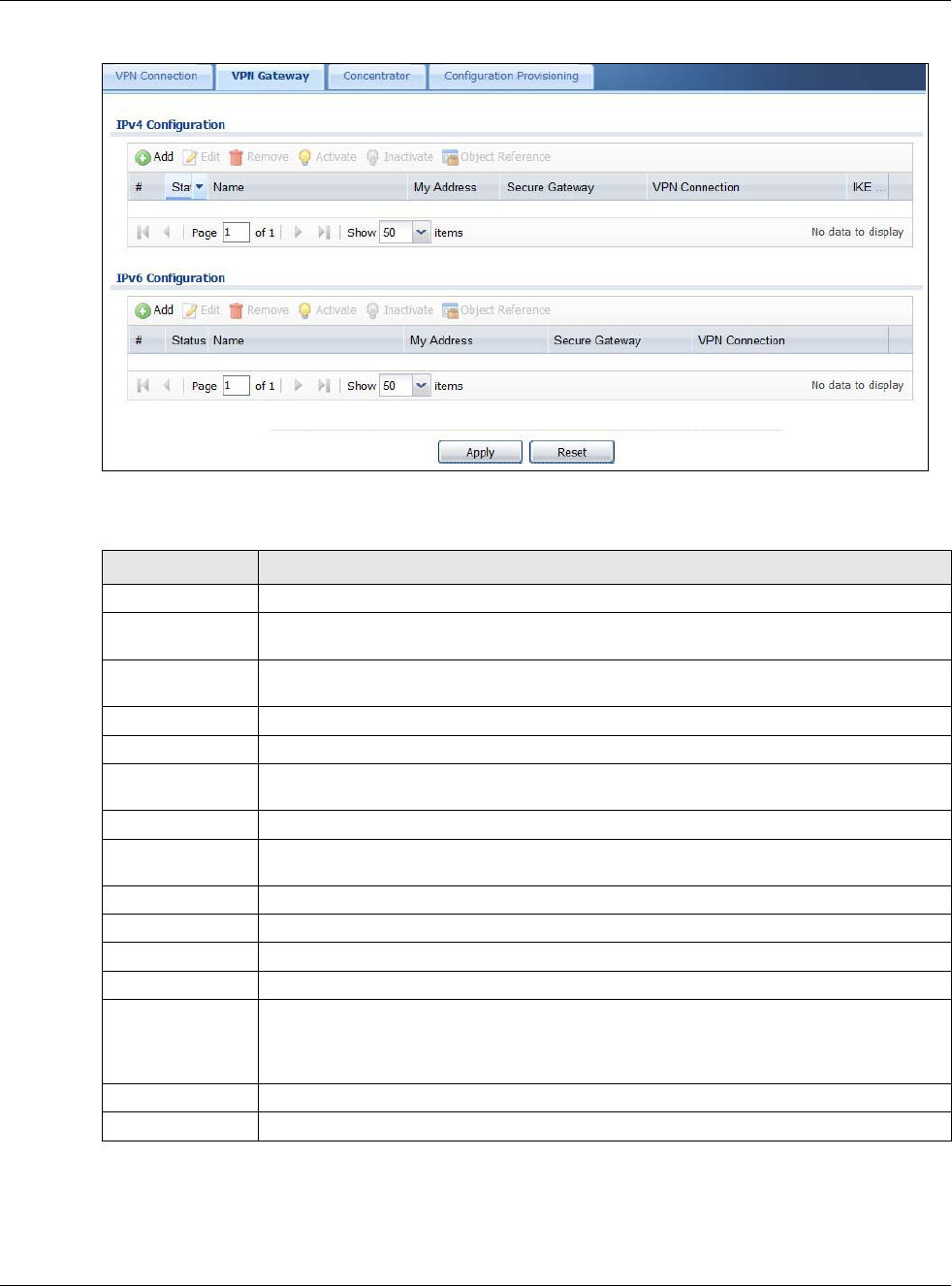
Chapter 21 IPSec VPN
USG20(W)-VPN Series User’s Guide
345
Figure 227 Configuration > VPN > IPSec VPN > VPN Gateway
Each field is discussed in the following table. See Section 21.3.1 on page 346 for more information.
Table 136 Configuration > VPN > IPSec VPN > VPN Gateway
LABEL DESCRIPTION
Add Click this to create a new entry.
Edit Double-click an entry or select it and click Edit to open a screen where you can modify
the entry’s settings.
Remove To remove an entry, select it and click Remove. The USG confirms you want to remove it
before doing so.
Activate To turn on an entry, select it and click Activate.
Inactivate To turn off an entry, select it and click Inactivate.
Object References Select an entry and click Object References to open a screen that shows which settings
use the entry. See Section 9.3.2 on page 163 for an example.
# This field is a sequential value, and it is not associated with a specific VPN gateway.
Status The activate (light bulb) icon is lit when the entry is active and dimmed when the entry is
inactive.
Name This field displays the name of the VPN gateway
My address This field displays the interface or a domain name the USG uses for the VPN gateway.
Secure Gateway This field displays the IP address(es) of the remote IPSec routers.
VPN Connection This field displays VPN connections that use this VPN gateway.
IKE Version This field displays whether the gateway is using IKEv1 or IKEv2. IKEv1 applies to IPv4
traffic only. IKEv2 applies to both IPv4 and IPv6 traffic. IKE (Internet Key Exchange) is a
protocol used in setting up security associations that allows two parties to send data
securely. See Section 21.1 on page 332 for more information on IKEv1 and IKEv2.
Apply Click Apply to save your changes back to the USG.
Reset Click Reset to return the screen to its last-saved settings.

Chapter 21 IPSec VPN
USG20(W)-VPN Series User’s Guide
346
21.3.1 The VPN Gateway Add/Edit Screen
The VPN Gateway Add/Edit screen allows you to create a new VPN gateway policy or edit an
existing one. To access this screen, go to the VPN Gateway summary screen (see Section 21.3 on
page 344), and click either the Add icon or an Edit icon.
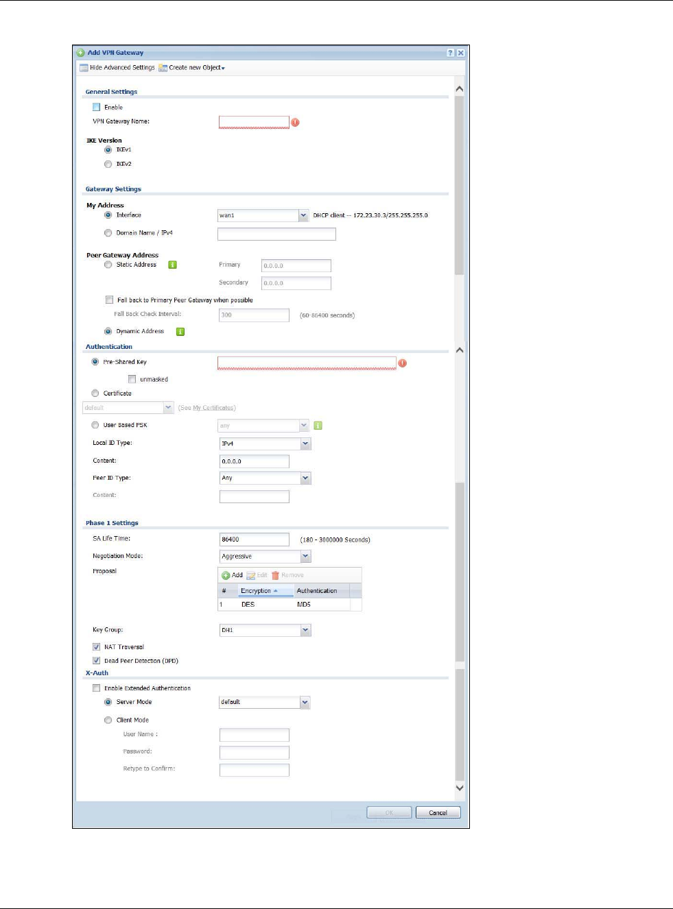
Chapter 21 IPSec VPN
USG20(W)-VPN Series User’s Guide
347
Figure 228 Configuration > VPN > IPSec VPN > VPN Gateway > Add/Edit
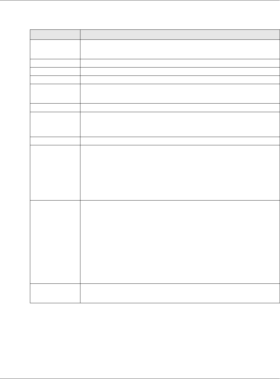
Chapter 21 IPSec VPN
USG20(W)-VPN Series User’s Guide
348
Each field is described in the following table.
Table 137 Configuration > VPN > IPSec VPN > VPN Gateway > Add/Edit
LABEL DESCRIPTION
Show Advanced
Settings / Hide
Advanced Settings
Click this button to display a greater or lesser number of configuration fields.
Create New Object Use to configure any new settings objects that you need to use in this screen.
General Settings
Enable Select this to activate the VPN Gateway policy.
VPN Gateway
Name Type the name used to identify this VPN gateway. You may use 1-31 alphanumeric
characters, underscores(_), or dashes (-), but the first character cannot be a number.
This value is case-sensitive.
IKE Version
IKEv1 / IKEv2 Select IKEv1 or IKEv2. IKEv1 applies to IPv4 traffic only. IKEv2 applies to both IPv4
and IPv6 traffic. IKE (Internet Key Exchange) is a protocol used in setting up security
associations that allows two parties to send data securely. See Section 21.1 on page
332 for more information on IKEv1 and IKEv2.
Gateway Settings
My Address Select how the IP address of the USG in the IKE SA is defined.
If you select Interface, select the Ethernet interface, VLAN interface, virtual Ethernet
interface, virtual VLAN interface or PPPoE/PPTP interface. The IP address of the USG in
the IKE SA is the IP address of the interface.
If you select Domain Name / IP, enter the domain name or the IP address of the
USG. The IP address of the USG in the IKE SA is the specified IP address or the IP
address corresponding to the domain name. 0.0.0.0 is not generally recommended as it
has the USG accept IPSec requests destined for any interface address on the USG.
Peer Gateway
Address Select how the IP address of the remote IPSec router in the IKE SA is defined.
Select Static Address to enter the domain name or the IP address of the remote IPSec
router. You can provide a second IP address or domain name for the USG to try if it
cannot establish an IKE SA with the first one.
Fall back to Primary Peer Gateway when possible: When you select this, if the
connection to the primary address goes down and the USG changes to using the
secondary connection, the USG will reconnect to the primary address when it
becomes available again and stop using the secondary connection. Users will lose
their VPN connection briefly while the USG changes back to the primary connection.
To use this, the peer device at the secondary address cannot be set to use a nailed-
up VPN connection. In the Fallback Check Interval field, set how often to check if
the primary address is available.
Select Dynamic Address if the remote IPSec router has a dynamic IP address (and
does not use DDNS).
Authentication Note: The USG and remote IPSec router must use the same authentication method to
establish the IKE SA.
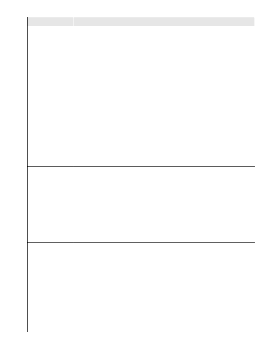
Chapter 21 IPSec VPN
USG20(W)-VPN Series User’s Guide
349
Pre-Shared Key Select this to have the USG and remote IPSec router use a pre-shared key (password)
to identify each other when they negotiate the IKE SA. Type the pre-shared key in the
field to the right. The pre-shared key can be:
• alphanumeric characters or ,;.|`~!@#$%^&*()_+\{}':./<>=-"
• pairs of hexadecimal (0-9, A-F) characters, preceded by “0x”.
Type “0x” at the beginning of a hexadecimal key. For example,
"0x0123456789ABCDEF" is in hexadecimal format; “0123456789ABCDEF” is in ASCII
format. If you use hexadecimal, you must enter twice as many characters since you
need to enter pairs.
The USG and remote IPSec router must use the same pre-shared key.
Select unmasked to see the pre-shared key in readable plain text.
Certificate Select this to have the USG and remote IPSec router use certificates to authenticate
each other when they negotiate the IKE SA. Then select the certificate the USG uses to
identify itself to the remote IPsec router.
This certificate is one of the certificates in My Certificates. If this certificate is self-
signed, import it into the remote IPsec router. If this certificate is signed by a CA, the
remote IPsec router must trust that CA.
Note: The IPSec routers must trust each other’s certificates.
The USG uses one of its Trusted Certificates to authenticate the remote IPSec
router’s certificate. The trusted certificate can be a self-signed certificate or that of a
trusted CA that signed the remote IPSec router’s certificate.
User-based PSK User-based PSK (IKEv1 only) generates and manages separate pre-shared keys for
every user. This enables multiple users, each with a unique key, to access the same
VPN gateway policy with one-to-one authentication and strong encryption. Access can
be denied on a per-user basis thus allowing VPN SA user-based policies. Click User-
Based PSK then select a user or group object who is allowed VPN SA access using this
VPN gateway policy. This is for IKEv1 only.
Local ID Type This field is read-only if the USG and remote IPSec router use certificates to identify
each other. Select which type of identification is used to identify the USG during
authentication. Choices are:
IPv4 or IPv6 - the USG is identified by an IP address
DNS - the USG is identified by a domain name
E-mail - the USG is identified by the string specified in this field
Content This field is read-only if the USG and remote IPSec router use certificates to identify
each other. Type the identity of the USG during authentication. The identity depends on
the Local ID Type.
IP - type an IP address; if you type 0.0.0.0, the USG uses the IP address specified in
the My Address field. This is not recommended in the following situations:
• There is a NAT router between the USG and remote IPSec router.
• You want the remote IPSec router to be able to distinguish between IPSec SA
requests that come from IPSec routers with dynamic WAN IP addresses.
In these situations, use a different IP address, or use a different Local ID Type.
DNS - type the fully qualified domain name (FQDN). This value is only used for
identification and can be any string that matches the peer ID string.
E-mail - the USG is identified by the string you specify here; you can use up to 63
ASCII characters including spaces, although trailing spaces are truncated. This value is
only used for identification and can be any string.
Table 137 Configuration > VPN > IPSec VPN > VPN Gateway > Add/Edit (continued)
LABEL DESCRIPTION
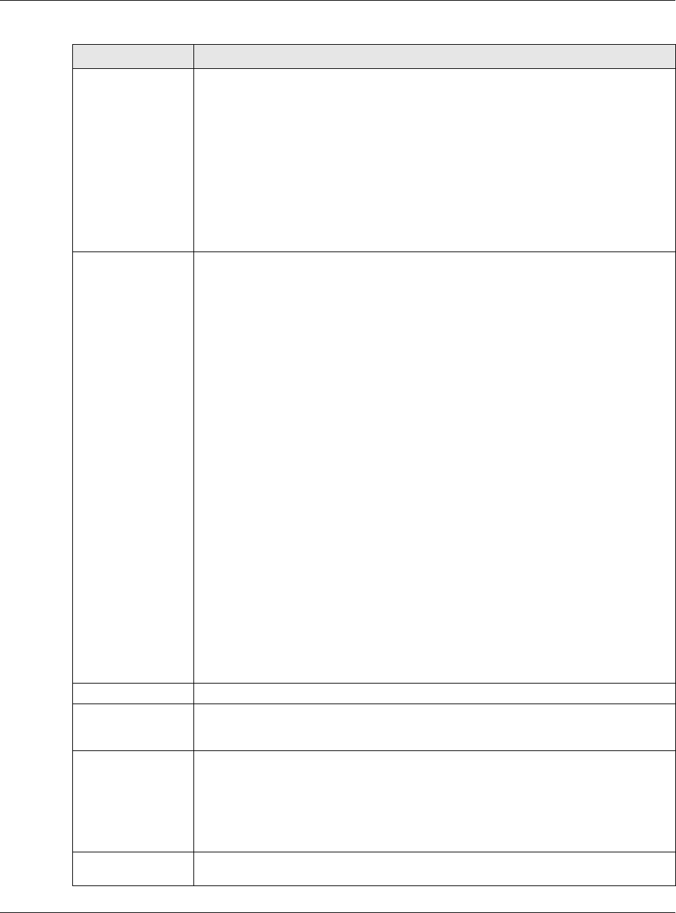
Chapter 21 IPSec VPN
USG20(W)-VPN Series User’s Guide
350
Peer ID Type Select which type of identification is used to identify the remote IPSec router during
authentication. Choices are:
IP - the remote IPSec router is identified by an IP address
DNS - the remote IPSec router is identified by a domain name
E-mail - the remote IPSec router is identified by the string specified in this field
Any - the USG does not check the identity of the remote IPSec router
If the USG and remote IPSec router use certificates, there is one more choice.
Subject Name - the remote IPSec router is identified by the subject name in the
certificate
Content This field is disabled if the Peer ID Type is Any. Type the identity of the remote IPSec
router during authentication. The identity depends on the Peer ID Type.
If the USG and remote IPSec router do not use certificates,
IP - type an IP address; see the note at the end of this description.
DNS - type the fully qualified domain name (FQDN). This value is only used for
identification and can be any string that matches the peer ID string.
E-mail - the remote IPSec router is identified by the string you specify here; you can
use up to 31 ASCII characters including spaces, although trailing spaces are truncated.
This value is only used for identification and can be any string.
If the USG and remote IPSec router use certificates, type the following fields from the
certificate used by the remote IPSec router.
IP - subject alternative name field; see the note at the end of this description.
DNS - subject alternative name field
E-mail - subject alternative name field
Subject Name - subject name (maximum 255 ASCII characters, including spaces)
Note: If Peer ID Type is IP, please read the rest of this section.
If you type 0.0.0.0, the USG uses the IP address specified in the Secure Gateway
Address field. This is not recommended in the following situations:
• There is a NAT router between the USG and remote IPSec router.
• You want the remote IPSec router to be able to distinguish between IPSec SA
requests that come from IPSec routers with dynamic WAN IP addresses.
In these situations, use a different IP address, or use a different Peer ID Type.
Phase 1 Settings
SA Life Time
(Seconds) Type the maximum number of seconds the IKE SA can last. When this time has passed,
the USG and remote IPSec router have to update the encryption and authentication
keys and re-negotiate the IKE SA. This does not affect any existing IPSec SAs, however.
Negotiation
Mode Select the negotiation mode to use to negotiate the IKE SA. Choices are
Main - this encrypts the USG’s and remote IPSec router’s identities but takes more
time to establish the IKE SA
Aggressive - this is faster but does not encrypt the identities
The USG and the remote IPSec router must use the same negotiation mode.
Proposal Use this section to manage the encryption algorithm and authentication algorithm pairs
the USG accepts from the remote IPSec router for negotiating the IKE SA.
Table 137 Configuration > VPN > IPSec VPN > VPN Gateway > Add/Edit (continued)
LABEL DESCRIPTION
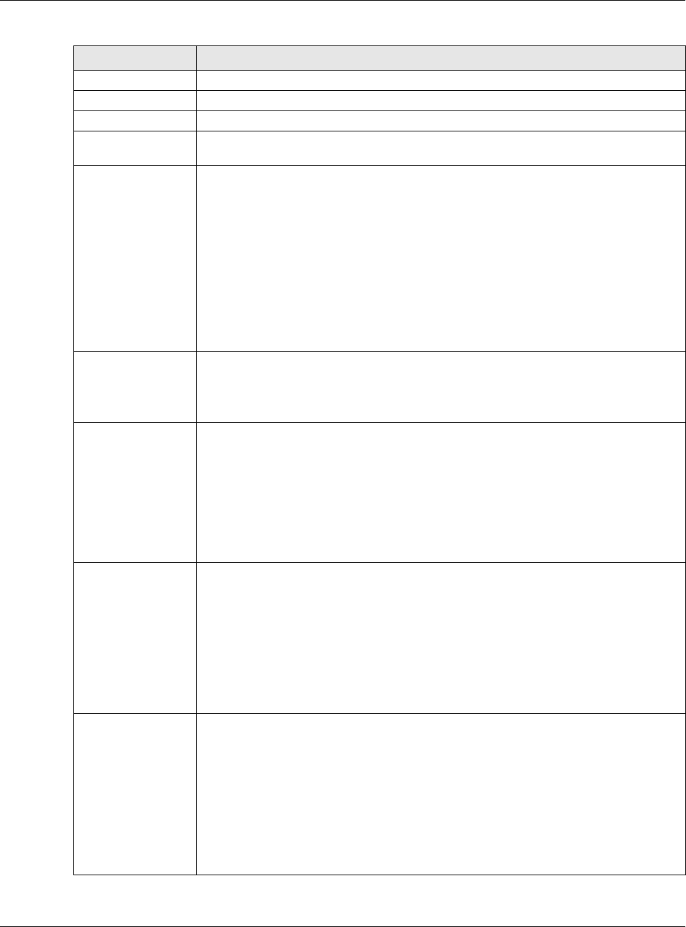
Chapter 21 IPSec VPN
USG20(W)-VPN Series User’s Guide
351
Add Click this to create a new entry.
Edit Select an entry and click this to be able to modify it.
Remove Select an entry and click this to delete it.
# This field is a sequential value, and it is not associated with a specific proposal. The
sequence of proposals should not affect performance significantly.
Encryption Select which key size and encryption algorithm to use in the IKE SA. Choices are:
DES - a 56-bit key with the DES encryption algorithm
3DES - a 168-bit key with the DES encryption algorithm
AES128 - a 128-bit key with the AES encryption algorithm
AES192 - a 192-bit key with the AES encryption algorithm
AES256 - a 256-bit key with the AES encryption algorithm
The USG and the remote IPSec router must use the same key size and encryption
algorithm. Longer keys require more processing power, resulting in increased latency
and decreased throughput.
Authentication Select which hash algorithm to use to authenticate packet data in the IPSec SA.
Choices are SHA1, SHA256, SHA512 and MD5. SHA is generally considered stronger
than MD5, but it is also slower.
The remote IPSec router must use the same authentication algorithm.
Key Group Select which Diffie-Hellman key group (DHx) you want to use for encryption keys.
Choices are:
DH1 - use a 768-bit random number
DH2 - use a 1024-bit random number
DH5 - use a 1536-bit random number
The longer the key, the more secure the encryption, but also the longer it takes to
encrypt and decrypt information. Both routers must use the same DH key group.
NAT Traversal Select this if any of these conditions are satisfied.
• This IKE SA might be used to negotiate IPSec SAs that use ESP as the active
protocol.
• There are one or more NAT routers between the USG and remote IPSec router, and
these routers do not support IPSec pass-thru or a similar feature.
The remote IPSec router must also enable NAT traversal, and the NAT routers have to
forward packets with UDP port 500 and UDP 4500 headers unchanged.
This field applies for IKEv1 only. NAT Traversal is always performed when you use
IKEv2.
Dead Peer
Detection (DPD) Select this check box if you want the USG to make sure the remote IPSec router is
there before it transmits data through the IKE SA. The remote IPSec router must
support DPD. If there has been no traffic for at least 15 seconds, the USG sends a
message to the remote IPSec router. If the remote IPSec router responds, the USG
transmits the data. If the remote IPSec router does not respond, the USG shuts down
the IKE SA.
If the remote IPSec router does not support DPD, see if you can use the VPN connection
connectivity check (see Section 21.2.1 on page 338).
This field applies for IKEv1 only. Dead Peer Detection (DPD) is always performed when
you use IKEv2.
Table 137 Configuration > VPN > IPSec VPN > VPN Gateway > Add/Edit (continued)
LABEL DESCRIPTION
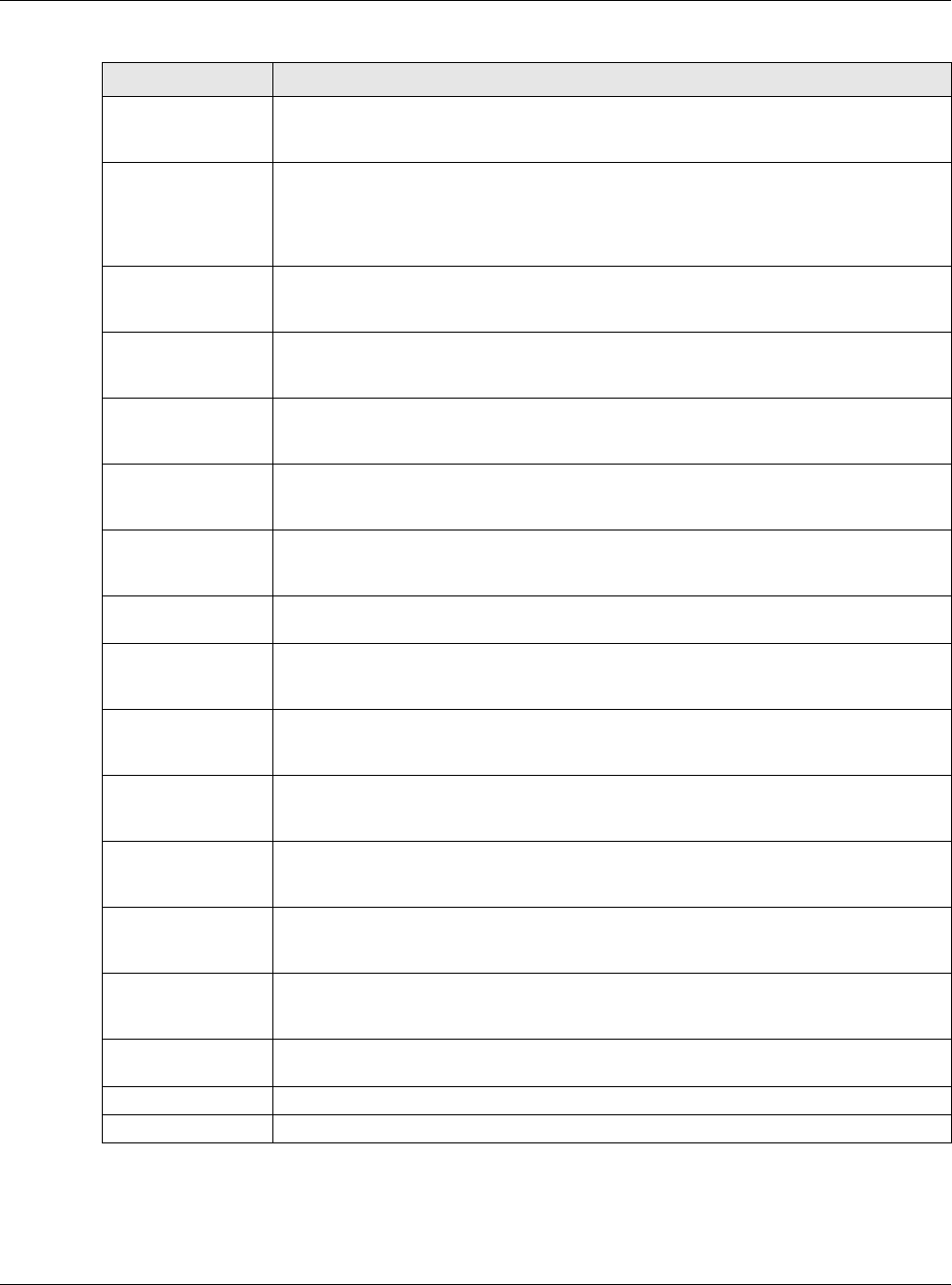
Chapter 21 IPSec VPN
USG20(W)-VPN Series User’s Guide
352
X Auth / Extended
Authentication
Protocol
This part of the screen displays X-Auth when using IKEv1 and Extended
Authentication Protocol when using IKEv2.
X-Auth This displays when using IKEv1. When different users use the same VPN tunnel to
connect to the USG (telecommuters sharing a tunnel for example), use X-auth to
enforce a user name and password check. This way even though telecommuters all
know the VPN tunnel’s security settings, each still has to provide a unique user name
and password.
Enable Extended
Authentication Select this if one of the routers (the USG or the remote IPSec router) verifies a user
name and password from the other router using the local user database and/or an
external server.
Server Mode Select this if the USG authenticates the user name and password from the remote
IPSec router. You also have to select the authentication method, which specifies how
the USG authenticates this information.
Client Mode Select this radio button if the USG provides a username and password to the remote
IPSec router for authentication. You also have to provide the User Name and the
Password.
User Name This field is required if the USG is in Client Mode for extended authentication. Type the
user name the USG sends to the remote IPSec router. The user name can be 1-31
ASCII characters. It is case-sensitive, but spaces are not allowed.
Password This field is required if the USG is in Client Mode for extended authentication. Type the
password the USG sends to the remote IPSec router. The password can be 1-31 ASCII
characters. It is case-sensitive, but spaces are not allowed.
Retype to
Confirm Type the exact same password again here to make sure an error was not made when
typing it originally.
Extended
Authentication
Protocol
This displays when using IKEv2. EAP uses a certificate for authentication.
Enable Extended
Authentication Select this if one of the routers (the USG or the remote IPSec router) verifies a user
name and password from the other router using the local user database and/or an
external server or a certificate.
Server Mode Select this if the USG authenticates the user name and password from the remote
IPSec router. You also have to select an AAA method, which specifies how the USG
authenticates this information and who may be authenticated (Allowed User).
Client Mode Select this radio button if the USG provides a username and password to the remote
IPSec router for authentication. You also have to provide the User Name and the
Password.
User Name This field is required if the USG is in Client Mode for extended authentication. Type the
user name the USG sends to the remote IPSec router. The user name can be 1-31
ASCII characters. It is case-sensitive, but spaces are not allowed.
Password This field is required if the USG is in Client Mode for extended authentication. Type the
password the USG sends to the remote IPSec router. The password can be 1-31 ASCII
characters. It is case-sensitive, but spaces are not allowed.
Retype to
Confirm Type the exact same password again here to make sure an error was not made when
typing it originally.
OK Click OK to save your settings and exit this screen.
Cancel Click Cancel to exit this screen without saving.
Table 137 Configuration > VPN > IPSec VPN > VPN Gateway > Add/Edit (continued)
LABEL DESCRIPTION
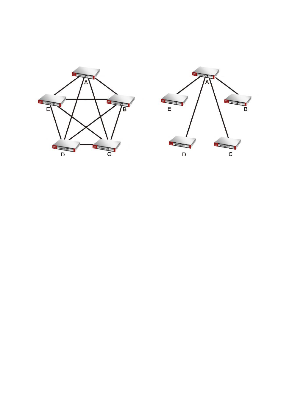
Chapter 21 IPSec VPN
USG20(W)-VPN Series User’s Guide
353
21.4 VPN Concentrator
A VPN concentrator combines several IPSec VPN connections into one secure network.
Figure 229 VPN Topologies (Fully Meshed and Hub and Spoke)
In a fully-meshed VPN topology (1 in the figure), there is a VPN connection between every pair of
routers. In a hub-and-spoke VPN topology (2 in the figure), there is a VPN connection between
each spoke router (B, C, D, and E) and the hub router (A), which uses the VPN concentrator. The
VPN concentrator routes VPN traffic between the spoke routers and itself.
A VPN concentrator reduces the number of VPN connections that you have to set up and maintain in
the network. You might also be able to consolidate the policy routes in each spoke router,
depending on the IP addresses and subnets of each spoke.
However a VPN concentrator is not for every situation. The hub router is a single failure point, so a
VPN concentrator is not as appropriate if the connection between spoke routers cannot be down
occasionally (maintenance, for example). There is also more burden on the hub router. It receives
VPN traffic from one spoke, decrypts it, inspects it to find out to which spoke to route it, encrypts it,
and sends it to the appropriate spoke. Therefore, a VPN concentrator is more suitable when there is
a minimum amount of traffic between spoke routers.
21.4.1 VPN Concentrator Requirements and Suggestions
Consider the following when using the VPN concentrator.
• The local IP addresses configured in the VPN rules should not overlap.
• The concentrator must have at least one separate VPN rule for each spoke. In the local policy,
specify the IP addresses of the networks with which the spoke is to be able to have a VPN tunnel.
This may require you to use more than one VPN rule for each spoke.
• To have all Internet access from the spoke routers go through the VPN tunnel, set the VPN rules
in the spoke routers to use 0.0.0.0 (any) as the remote IP address.
• Your security policies can still block VPN packets.
12
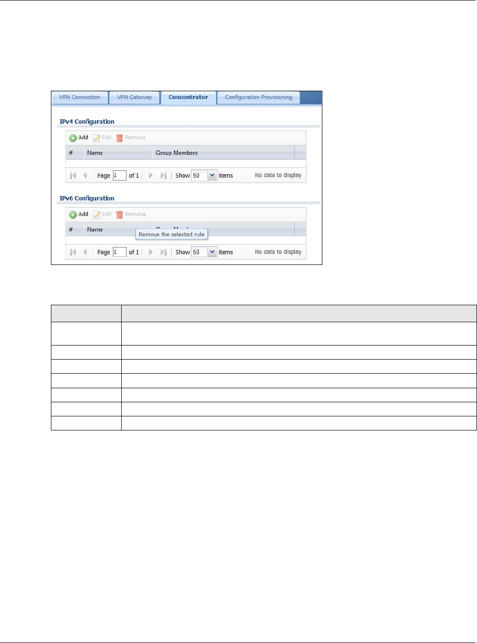
Chapter 21 IPSec VPN
USG20(W)-VPN Series User’s Guide
354
21.4.2 VPN Concentrator Screen
The VPN Concentrator summary screen displays the VPN concentrators in the USG. To access this
screen, click Configuration > VPN > IPSec VPN > Concentrator.
Figure 230 Configuration > VPN > IPSec VPN > Concentrator
Each field is discussed in the following table. See Section 21.4.3 on page 354 for more information.
21.4.3 The VPN Concentrator Add/Edit Screen
Use the VPN Concentrator Add/Edit screen to create or edit a VPN concentrator. To access this
screen, go to the VPN Concentrator summary screen (see Section 21.4 on page 353), and click
either the Add icon or an Edit icon.
Table 138 Configuration > VPN > IPSec VPN > Concentrator
LABEL DESCRIPTION
IPv4/IPv6
Configuration
Choose to configure for IPv4 or IPv6 traffic.
Add Click this to create a new entry.
Edit Select an entry and click this to be able to modify it.
Remove Select an entry and click this to delete it.
# This field is a sequential value, and it is not associated with a specific concentrator.
Name This field displays the name of the VPN concentrator.
Group Members These are the VPN connection policies that are part of the VPN concentrator.
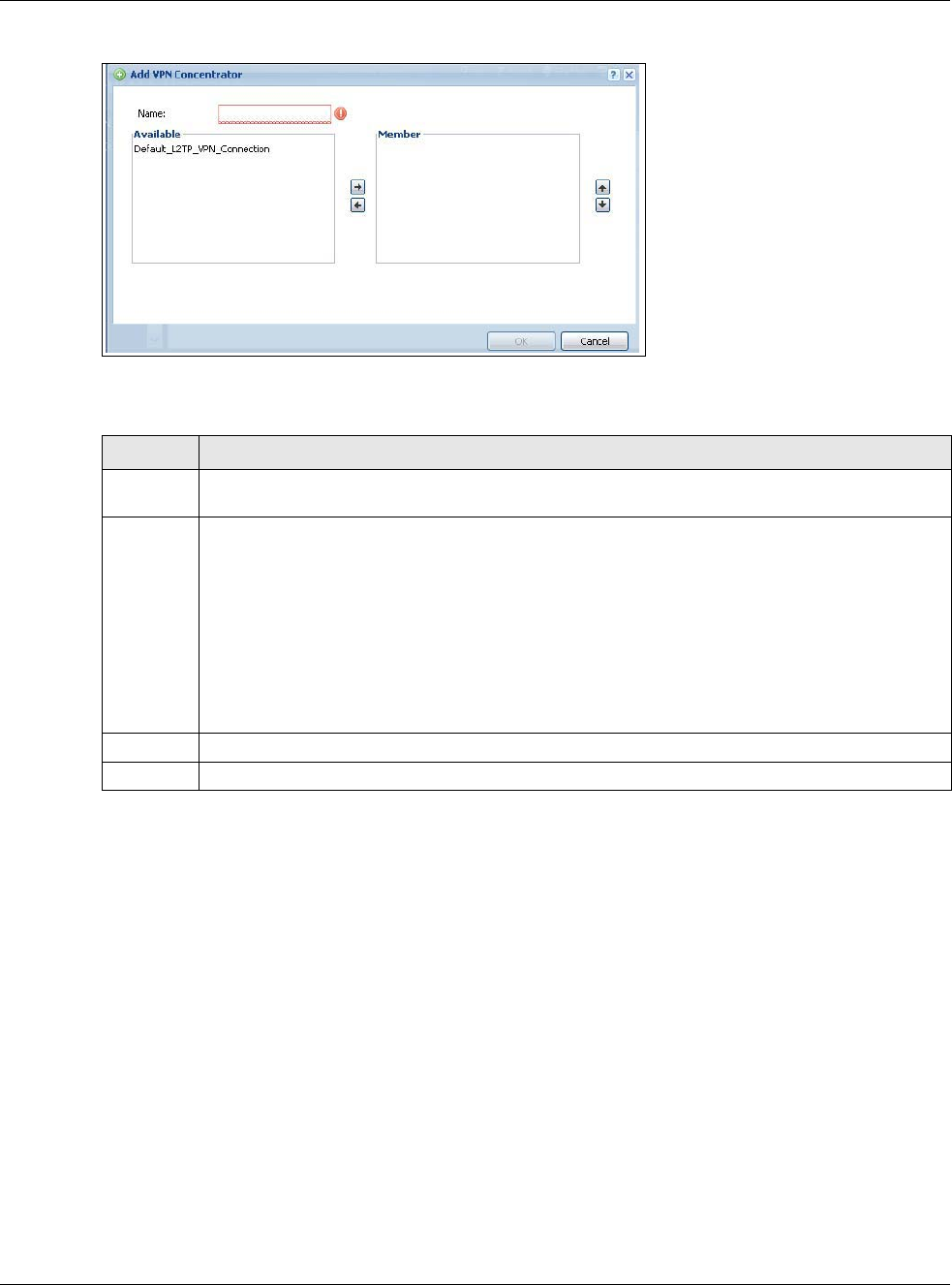
Chapter 21 IPSec VPN
USG20(W)-VPN Series User’s Guide
355
Figure 231 Configuration > VPN > IPSec VPN > Concentrator > Add/Edit
Each field is described in the following table.
21.5 USG IPSec VPN Client Configuration Provisioning
Use the Configuration > VPN > IPSec VPN > Configuration Provisioning screen to configure
who can retrieve VPN rule settings from the USG using the USG IPSec VPN Client. In the USG IPSec
VPN Client, you just need to enter the IP address of the USG to get all the VPN rule settings
automatically. You do not need to manually configure all rule settings in the USG IPSec VPN client.
VPN rules for the USG IPSec VPN Client have certain restrictions. They must not contain the
following settings:
•AH active protocol
•NULL encryption
•SHA512 authentication
• A subnet or range remote policy
Table 139 VPN > IPSec VPN > Concentrator > Add/Edit
LABEL DESCRIPTION
Name Enter the name of the concentrator. You may use 1-31 alphanumeric characters, underscores(_),
or dashes (-), but the first character cannot be a number. This value is case-sensitive.
Member Select the concentrator’s IPSec VPN connection policies.
Note: You must disable policy enforcement in each member. See Section 21.2.1 on page 338.
IPSec VPN connection policies that do not belong to a VPN concentrator appear under Available.
Select any VPN connection policies that you want to add to the VPN concentrator and click the
right arrow button to add them.
The VPN concentrator’s member VPN connections appear under Member. Select any VPN
connections that you want to remove from the VPN concentrator, and click the left arrow button
to remove them.
OK Click OK to save your changes in the USG.
Cancel Click Cancel to exit this screen without saving.
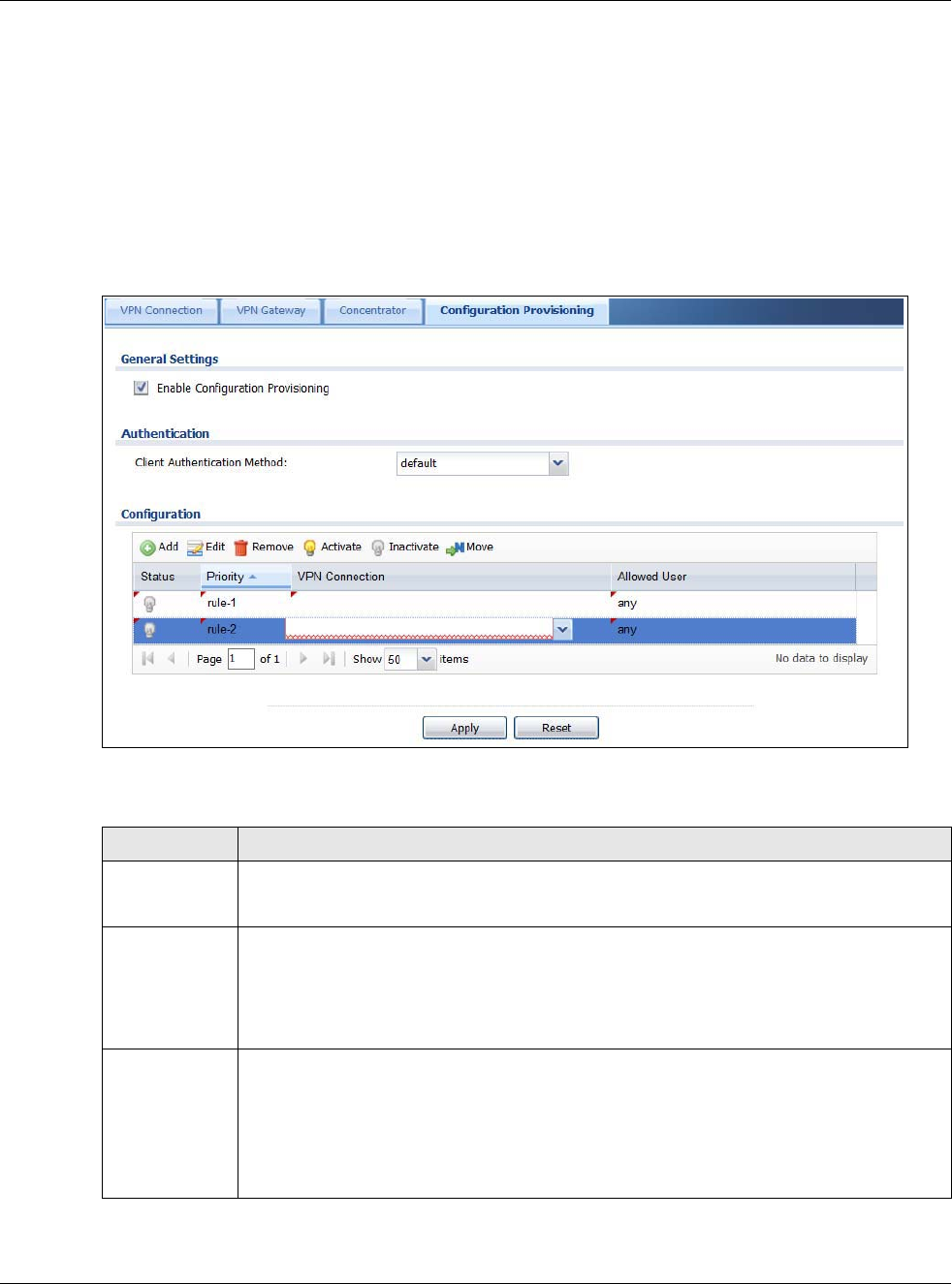
Chapter 21 IPSec VPN
USG20(W)-VPN Series User’s Guide
356
The following VPN Gateway rules configured on the USG cannot be provisioned to the IPSec VPN
Client:
• IPv4 rules with IKEv2 version
• IPv4 rules with User-based PSK authentication
•IPv6 rules
In the USG Quick Setup wizard, you can use the VPN Settings for Configuration Provisioning
wizard to create a VPN rule that will not violate these restrictions.
Figure 232 Configuration > VPN > IPSec VPN > Configuration Provisioning
Each field is discussed in the following table.
Table 140 Configuration > VPN > IPSec VPN > Configuration Provisioning
LABEL DESCRIPTION
Enable
Configuration
Provisioning
Select this for users to be able to retrieve VPN rule settings using the USG IPSec VPN client.
Client
Authentication
Method
Choose how users should be authenticated. They can be authenticated using the local
database on the USG or an external authentication database such as LDAP, Active Directory
or RADIUS. default is a method you configured in Object > Auth Method. You may
configure multiple methods there. If you choose the local database on the USG, then
configure users using the Object > User/Group screen. If you choose LDAP, Active
Directory or RADIUS authentication servers, then configure users on the respective server.
Configuration When you add or edit a configuration provisioning entry, you are allowed to set the VPN
Connection and Allowed User fields.
Duplicate entries are not allowed. You cannot select the same VPN Connection and
Allowed User pair in a new entry if the same pair exists in a previous entry.
You can bind different rules to the same user, but the USG will only allow VPN rule setting
retrieval for the first match found.
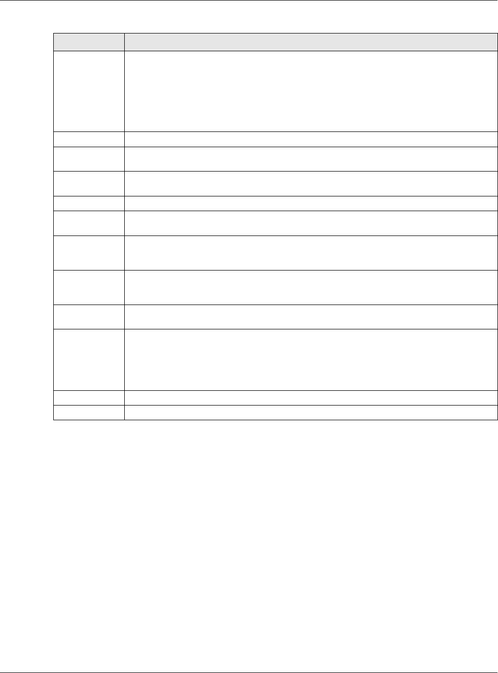
Chapter 21 IPSec VPN
USG20(W)-VPN Series User’s Guide
357
21.6 IPSec VPN Background Information
Here is some more detailed IPSec VPN background information.
IKE SA Overview
The IKE SA provides a secure connection between the USG and remote IPSec router.
It takes several steps to establish an IKE SA. The negotiation mode determines how many. There
are two negotiation modes--main mode and aggressive mode. Main mode provides better security,
while aggressive mode is faster.
Note: Both routers must use the same negotiation mode.
These modes are discussed in more detail in Negotiation Mode on page 361. Main mode is used in
various examples in the rest of this section.
Add Click Add to bind a configured VPN rule to a user or group. Only that user or group may
then retrieve the specified VPN rule settings.
If you click Add without selecting an entry in advance then the new entry appears as the
first entry. Entry order is important as the USG searches entries in the order listed here to
find a match. After a match is found, the USG stops searching. If you want to add an entry
as number three for example, then first select entry 2 and click Add. To reorder an entry,
use Move.
Edit Select an existing entry and click Edit to change its settings.
Remove To remove an entry, select it and click Remove. The USG confirms you want to remove it
before doing so.
Activate To turn on an entry, select it and click Activate. Make sure that Enable Configuration
Provisioning is also selected.
Inactivate To turn off an entry, select it and click Inactivate.
Move Use Move to reorder a selected entry. Select an entry, click Move, type the number where
the entry should be moved, press <ENTER>, then click Apply.
Status This icon shows if the entry is active (yellow) or not (gray). VPN rule settings can only be
retrieved when the entry is activated (and Enable Configuration Provisioning is also
selected).
Priority Priority shows the order of the entry in the list. Entry order is important as the USG
searches entries in the order listed here to find a match. After a match is found the USG
stops searching.
VPN Connection This field shows all configured VPN rules that match the rule criteria for the USG IPSec VPN
client. Select a rule to bind to the associated user or group.
Allowed User Select which user or group of users is allowed to retrieve the associated VPN rule settings
using the USG IPSec VPN client. A user may belong to a number of groups. If entries are
configured for different groups, the USG will allow VPN rule setting retrieval based on the
first match found.
Users of type admin or limited-admin are not allowed.
Apply Click Apply to save your changes back to the USG.
Reset Click Reset to return the screen to its last-saved settings.
Table 140 Configuration > VPN > IPSec VPN > Configuration Provisioning (continued)
LABEL DESCRIPTION
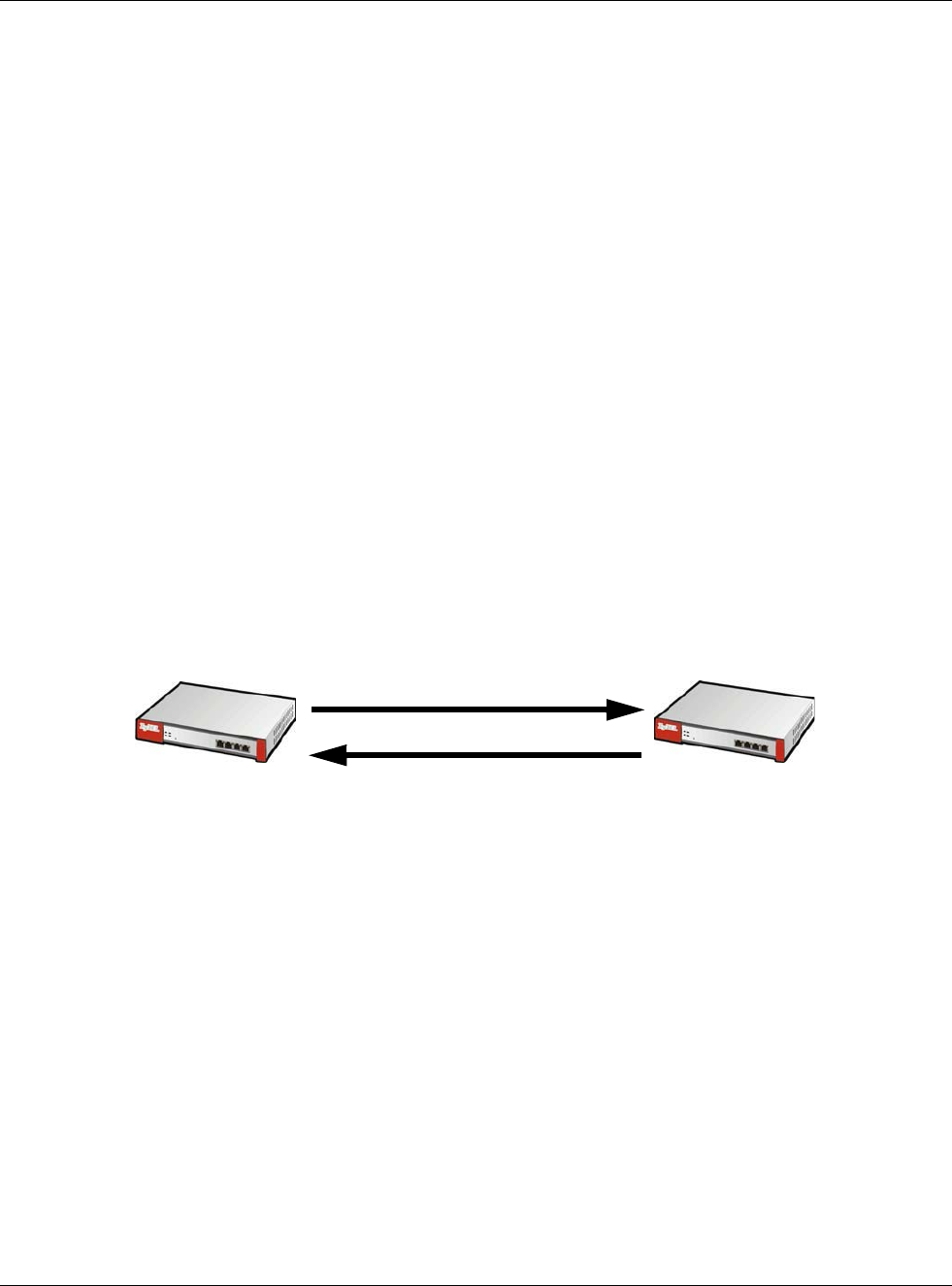
Chapter 21 IPSec VPN
USG20(W)-VPN Series User’s Guide
358
The USG supports IKEv1 and IKEv2. See Section 21.1 on page 332 for more information.
IP Addresses of the USG and Remote IPSec Router
To set up an IKE SA, you have to specify the IP addresses of the USG and remote IPSec router. You
can usually enter a static IP address or a domain name for either or both IP addresses. Sometimes,
your USG might offer another alternative, such as using the IP address of a port or interface, as
well.
You can also specify the IP address of the remote IPSec router as 0.0.0.0. This means that the
remote IPSec router can have any IP address. In this case, only the remote IPSec router can initiate
an IKE SA because the USG does not know the IP address of the remote IPSec router. This is often
used for telecommuters.
IKE SA Proposal
The IKE SA proposal is used to identify the encryption algorithm, authentication algorithm, and
Diffie-Hellman (DH) key group that the USG and remote IPSec router use in the IKE SA. In main
mode, this is done in steps 1 and 2, as illustrated next.
Figure 233 IKE SA: Main Negotiation Mode, Steps 1 - 2: IKE SA Proposal
The USG sends one or more proposals to the remote IPSec router. (In some devices, you can only
set up one proposal.) Each proposal consists of an encryption algorithm, authentication algorithm,
and DH key group that the USG wants to use in the IKE SA. The remote IPSec router selects an
acceptable proposal and sends the accepted proposal back to the USG. If the remote IPSec router
rejects all of the proposals, the USG and remote IPSec router cannot establish an IKE SA.
Note: Both routers must use the same encryption algorithm, authentication algorithm,
and DH key group.
In most USGs, you can select one of the following encryption algorithms for each proposal. The
algorithms are listed in order from weakest to strongest.
• Data Encryption Standard (DES) is a widely used method of data encryption. It applies a 56-bit
key to each 64-bit block of data.
• Triple DES (3DES) is a variant of DES. It iterates three times with three separate keys, effectively
tripling the strength of DES.
• Advanced Encryption Standard (AES) is a newer method of data encryption that also uses a
secret key. AES applies a 128-bit key to 128-bit blocks of data. It is faster than 3DES.
One or more proposals, each one consisting of:
- encryption algorithm
- authentication algorithm
- Diffie-Hellman key group
1
2
XY
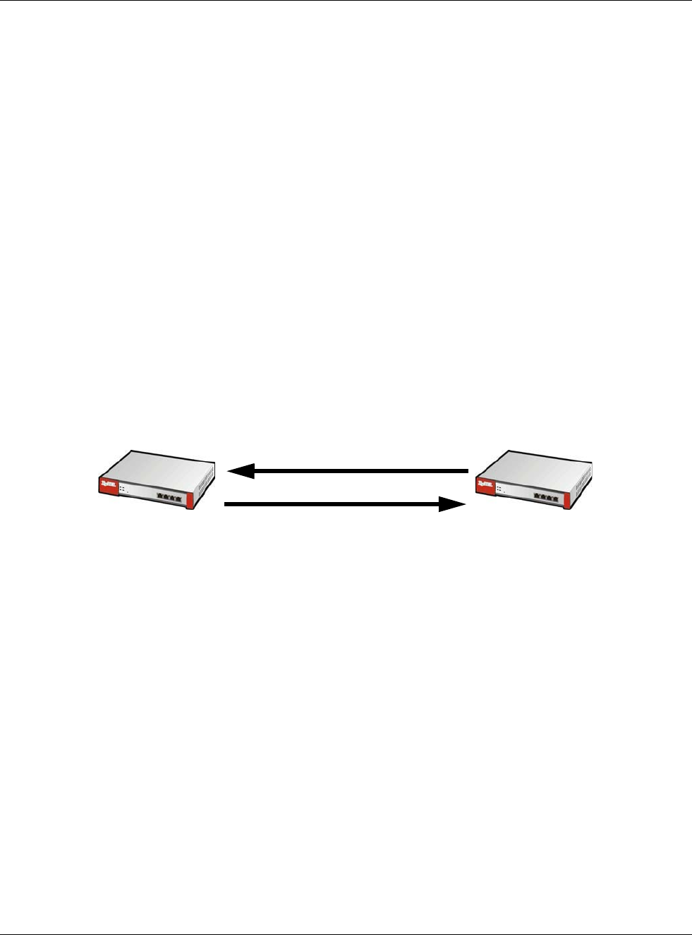
Chapter 21 IPSec VPN
USG20(W)-VPN Series User’s Guide
359
Some USGs also offer stronger forms of AES that apply 192-bit or 256-bit keys to 128-bit blocks of
data.
In most USGs, you can select one of the following authentication algorithms for each proposal. The
algorithms are listed in order from weakest to strongest.
• MD5 (Message Digest 5) produces a 128-bit digest to authenticate packet data.
• SHA1 (Secure Hash Algorithm) produces a 160-bit digest to authenticate packet data.
• SHA256 (Secure Hash Algorithm) produces a 256-bit digest to authenticate packet data.
• SHA512 (Secure Hash Algorithm) produces a 512-bit digest to authenticate packet data.
See Diffie-Hellman (DH) Key Exchange on page 359 for more information about DH key groups.
Diffie-Hellman (DH) Key Exchange
The USG and the remote IPSec router use DH public-key cryptography to establish a shared secret.
The shared secret is then used to generate encryption keys for the IKE SA and IPSec SA. In main
mode, this is done in steps 3 and 4, as illustrated next.
Figure 234 IKE SA: Main Negotiation Mode, Steps 3 - 4: DH Key Exchange
DH public-key cryptography is based on DH key groups. Each key group is a fixed number of bits
long. The longer the key, the more secure the encryption, but also the longer it takes to encrypt
and decrypt information. For example, DH2 keys (1024 bits) are more secure than DH1 keys (768
bits), but DH2 keys take longer to encrypt and decrypt.
Authentication
Before the USG and remote IPSec router establish an IKE SA, they have to verify each other’s
identity. This process is based on pre-shared keys and router identities.
In main mode, the USG and remote IPSec router authenticate each other in steps 5 and 6, as
illustrated below. The identities are also encrypted using the encryption algorithm and encryption
key the USG and remote IPSec router selected in previous steps.
Diffie-Hellman key exchange
3
4
XY
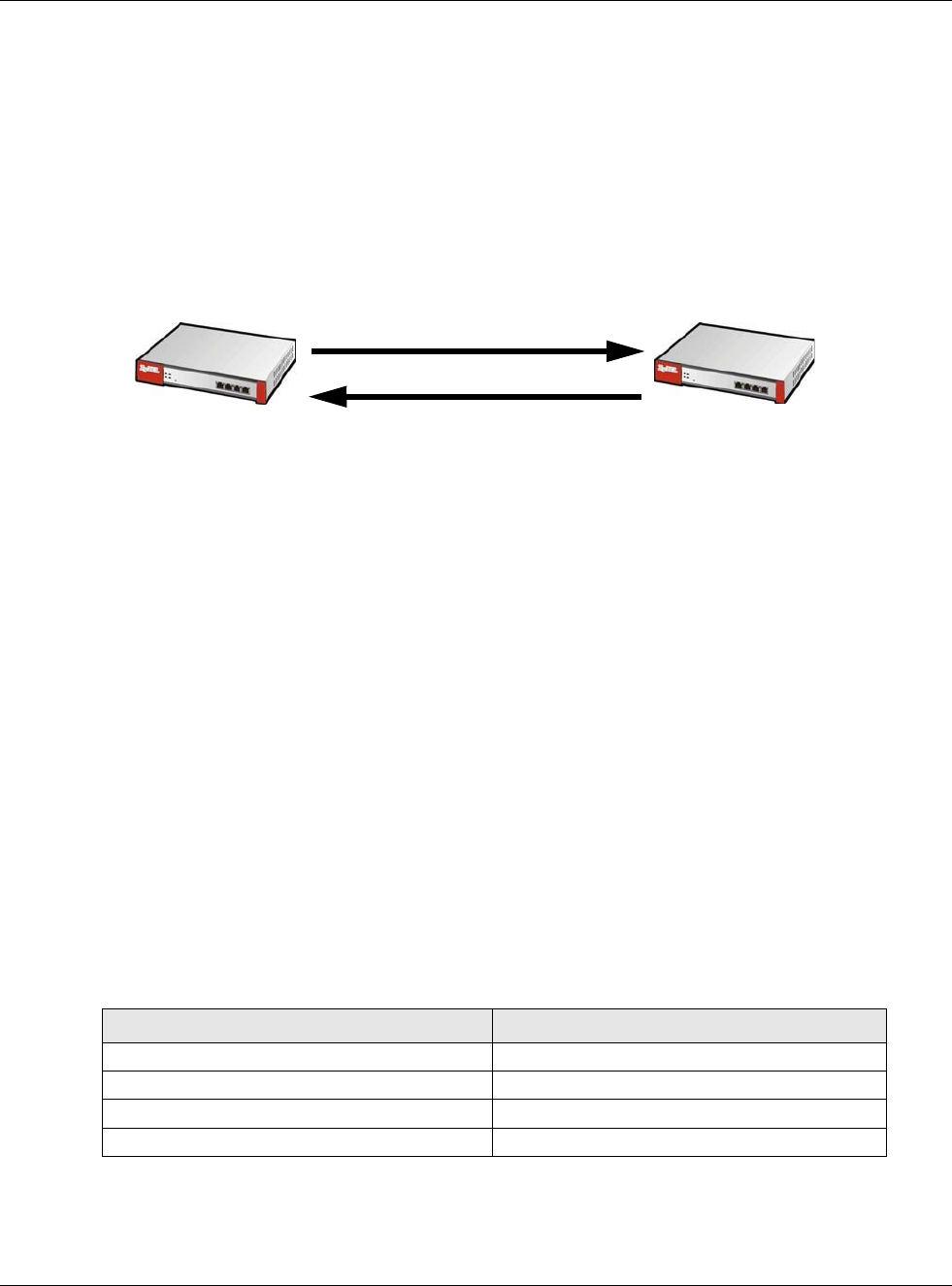
Chapter 21 IPSec VPN
USG20(W)-VPN Series User’s Guide
360
Figure 235 IKE SA: Main Negotiation Mode, Steps 5 - 6: Authentication (continued)
You have to create (and distribute) a pre-shared key. The USG and remote IPSec router use it in
the authentication process, though it is not actually transmitted or exchanged.
Note: The USG and the remote IPSec router must use the same pre-shared key.
Router identity consists of ID type and content. The ID type can be domain name, IP address, or e-
mail address, and the content is a (properly-formatted) domain name, IP address, or e-mail
address. The content is only used for identification. Any domain name or e-mail address that you
enter does not have to actually exist. Similarly, any domain name or IP address that you enter does
not have to correspond to the USG’s or remote IPSec router’s properties.
The USG and the remote IPSec router have their own identities, so both of them must store two
sets of information, one for themselves and one for the other router. Local ID type and content
refers to the ID type and content that applies to the router itself, and peer ID type and content
refers to the ID type and content that applies to the other router.
Note: The USG’s local and peer ID type and content must match the remote IPSec
router’s peer and local ID type and content, respectively.
For example, in Table 141 on page 360, the USG and the remote IPSec router authenticate each
other successfully. In contrast, in Table 142 on page 361, the USG and the remote IPSec router
cannot authenticate each other and, therefore, cannot establish an IKE SA.
Step 5:
pre-shared key
USG identity, consisting of
- ID type
- content
Step 6:
pre-shared key
Remote IPSec router identity, consisting of
- ID type
- content
Table 141 VPN Example: Matching ID Type and Content
USG REMOTE IPSEC ROUTER
Local ID type: E-mail Local ID type: IP
Local ID content: tom@yourcompany.com Local ID content: 1.1.1.2
Peer ID type: IP Peer ID type: E-mail
Peer ID content: 1.1.1.2 Peer ID content: tom@yourcompany.com
5
6
XY
Chapter 21 IPSec VPN
USG20(W)-VPN Series User’s Guide
361
It is also possible to configure the USG to ignore the identity of the remote IPSec router. In this
case, you usually set the peer ID type to Any. This is less secure, so you should only use this if your
USG provides another way to check the identity of the remote IPSec router (for example, extended
authentication) or if you are troubleshooting a VPN tunnel.
Additional Topics for IKE SA
This section provides more information about IKE SA.
Negotiation Mode
There are two negotiation modes--main mode and aggressive mode. Main mode provides better
security, while aggressive mode is faster.
Main mode takes six steps to establish an IKE SA.
Steps 1 - 2: The USG sends its proposals to the remote IPSec router. The remote IPSec router
selects an acceptable proposal and sends it back to the USG.
Steps 3 - 4: The USG and the remote IPSec router exchange pre-shared keys for authentication
and participate in a Diffie-Hellman key exchange, based on the accepted DH key group, to establish
a shared secret.
Steps 5 - 6: Finally, the USG and the remote IPSec router generate an encryption key (from the
shared secret), encrypt their identities, and exchange their encrypted identity information for
authentication.
In contrast, aggressive mode only takes three steps to establish an IKE SA. Aggressive mode does
not provide as much security because the identity of the USG and the identity of the remote IPSec
router are not encrypted. It is usually used in remote-access situations, where the address of the
initiator is not known by the responder and both parties want to use pre-shared keys for
authentication. For example, the remote IPSec router may be a telecommuter who does not have a
static IP address.
VPN, NAT, and NAT Traversal
In the following example, there is another router (A) between router X and router Y.
Figure 236 VPN/NAT Example
If router A does NAT, it might change the IP addresses, port numbers, or both. If router X and
router Y try to establish a VPN tunnel, the authentication fails because it depends on this
information. The routers cannot establish a VPN tunnel.
Table 142 VPN Example: Mismatching ID Type and Content
USG REMOTE IPSEC ROUTER
Local ID type: E-mail Local ID type: IP
Local ID content: tom@yourcompany.com Local ID content: 1.1.1.2
Peer ID type: IP Peer ID type: E-mail
Peer ID content: 1.1.1.20 Peer ID content: tom@yourcompany.com
Chapter 21 IPSec VPN
USG20(W)-VPN Series User’s Guide
362
Most routers like router A now have an IPSec pass-thru feature. This feature helps router A
recognize VPN packets and route them appropriately. If router A has this feature, router X and
router Y can establish a VPN tunnel as long as the active protocol is ESP. (See Active Protocol on
page 363 for more information about active protocols.)
If router A does not have an IPSec pass-thru or if the active protocol is AH, you can solve this
problem by enabling NAT traversal. In NAT traversal, router X and router Y add an extra header to
the IKE SA and IPSec SA packets. If you configure router A to forward these packets unchanged,
router X and router Y can establish a VPN tunnel.
You have to do the following things to set up NAT traversal.
• Enable NAT traversal on the USG and remote IPSec router.
• Configure the NAT router to forward packets with the extra header unchanged. (See the field
description for detailed information about the extra header.)
The extra header may be UDP port 500 or UDP port 4500, depending on the standard(s) the USG
and remote IPSec router support.
X-Auth / Extended Authentication
X-Auth / Extended authentication is often used when multiple IPSec routers use the same VPN
tunnel to connect to a single IPSec router. For example, this might be used with telecommuters.
In extended authentication, one of the routers (the USG or the remote IPSec router) provides a
user name and password to the other router, which uses a local user database and/or an external
server to verify the user name and password. If the user name or password is wrong, the routers
do not establish an IKE SA.
You can set up the USG to provide a user name and password to the remote IPSec router, or you
can set up the USG to check a user name and password that is provided by the remote IPSec
router.
If you use extended authentication, it takes four more steps to establish an IKE SA. These steps
occur at the end, regardless of the negotiation mode (steps 7-10 in main mode, steps 4-7 in
aggressive mode).
Certificates
It is possible for the USG and remote IPSec router to authenticate each other with certificates. In
this case, you do not have to set up the pre-shared key, local identity, or remote identity because
the certificates provide this information instead.
A
XY
Chapter 21 IPSec VPN
USG20(W)-VPN Series User’s Guide
363
• Instead of using the pre-shared key, the USG and remote IPSec router check the signatures on
each other’s certificates. Unlike pre-shared keys, the signatures do not have to match.
• The local and peer ID type and content come from the certificates.
Note: You must set up the certificates for the USG and remote IPSec router first.
IPSec SA Overview
Once the USG and remote IPSec router have established the IKE SA, they can securely negotiate an
IPSec SA through which to send data between computers on the networks.
Note: The IPSec SA stays connected even if the underlying IKE SA is not available
anymore.
This section introduces the key components of an IPSec SA.
Local Network and Remote Network
In an IPSec SA, the local network, the one(s) connected to the USG, may be called the local policy.
Similarly, the remote network, the one(s) connected to the remote IPSec router, may be called the
remote policy.
Active Protocol
The active protocol controls the format of each packet. It also specifies how much of each packet is
protected by the encryption and authentication algorithms. IPSec VPN includes two active
protocols, AH (Authentication Header, RFC 2402) and ESP (Encapsulating Security Payload, RFC
2406).
Note: The USG and remote IPSec router must use the same active protocol.
Usually, you should select ESP. AH does not support encryption, and ESP is more suitable with NAT.
Encapsulation
There are two ways to encapsulate packets. Usually, you should use tunnel mode because it is more
secure. Transport mode is only used when the IPSec SA is used for communication between the
USG and remote IPSec router (for example, for remote management), not between computers on
the local and remote networks.
Note: The USG and remote IPSec router must use the same encapsulation.
These modes are illustrated below.
Figure 237 VPN: Transport and Tunnel Mode Encapsulation
Original Packet IP Header TCP
Header
Data
Transport Mode Packet IP Header AH/ESP
Header
TCP
Header
Data
Chapter 21 IPSec VPN
USG20(W)-VPN Series User’s Guide
364
In tunnel mode, the USG uses the active protocol to encapsulate the entire IP packet. As a result,
there are two IP headers:
• Outside header: The outside IP header contains the IP address of the USG or remote IPSec
router, whichever is the destination.
• Inside header: The inside IP header contains the IP address of the computer behind the USG or
remote IPSec router. The header for the active protocol (AH or ESP) appears between the IP
headers.
In transport mode, the encapsulation depends on the active protocol. With AH, the USG includes
part of the original IP header when it encapsulates the packet. With ESP, however, the USG does
not include the IP header when it encapsulates the packet, so it is not possible to verify the
integrity of the source IP address.
IPSec SA Proposal and Perfect Forward Secrecy
An IPSec SA proposal is similar to an IKE SA proposal (see IKE SA Proposal on page 358), except
that you also have the choice whether or not the USG and remote IPSec router perform a new DH
key exchange every time an IPSec SA is established. This is called Perfect Forward Secrecy (PFS).
If you enable PFS, the USG and remote IPSec router perform a DH key exchange every time an
IPSec SA is established, changing the root key from which encryption keys are generated. As a
result, if one encryption key is compromised, other encryption keys remain secure.
If you do not enable PFS, the USG and remote IPSec router use the same root key that was
generated when the IKE SA was established to generate encryption keys.
The DH key exchange is time-consuming and may be unnecessary for data that does not require
such security.
PFS is ignored in initial IKEv2 authentication but is used when reauthenticating.
Additional Topics for IPSec SA
This section provides more information about IPSec SA in your USG.
Authentication and the Security Parameter Index (SPI)
For authentication, the USG and remote IPSec router use the SPI, instead of pre-shared keys, ID
type and content. The SPI is an identification number.
Note: The USG and remote IPSec router must use the same SPI.
NAT for Inbound and Outbound Traffic
The USG can translate the following types of network addresses in IPSec SA.
Tunnel Mode Packet IP Header AH/ESP
Header
IP Header TCP
Header
Data
Figure 237 VPN: Transport and Tunnel Mode Encapsulation
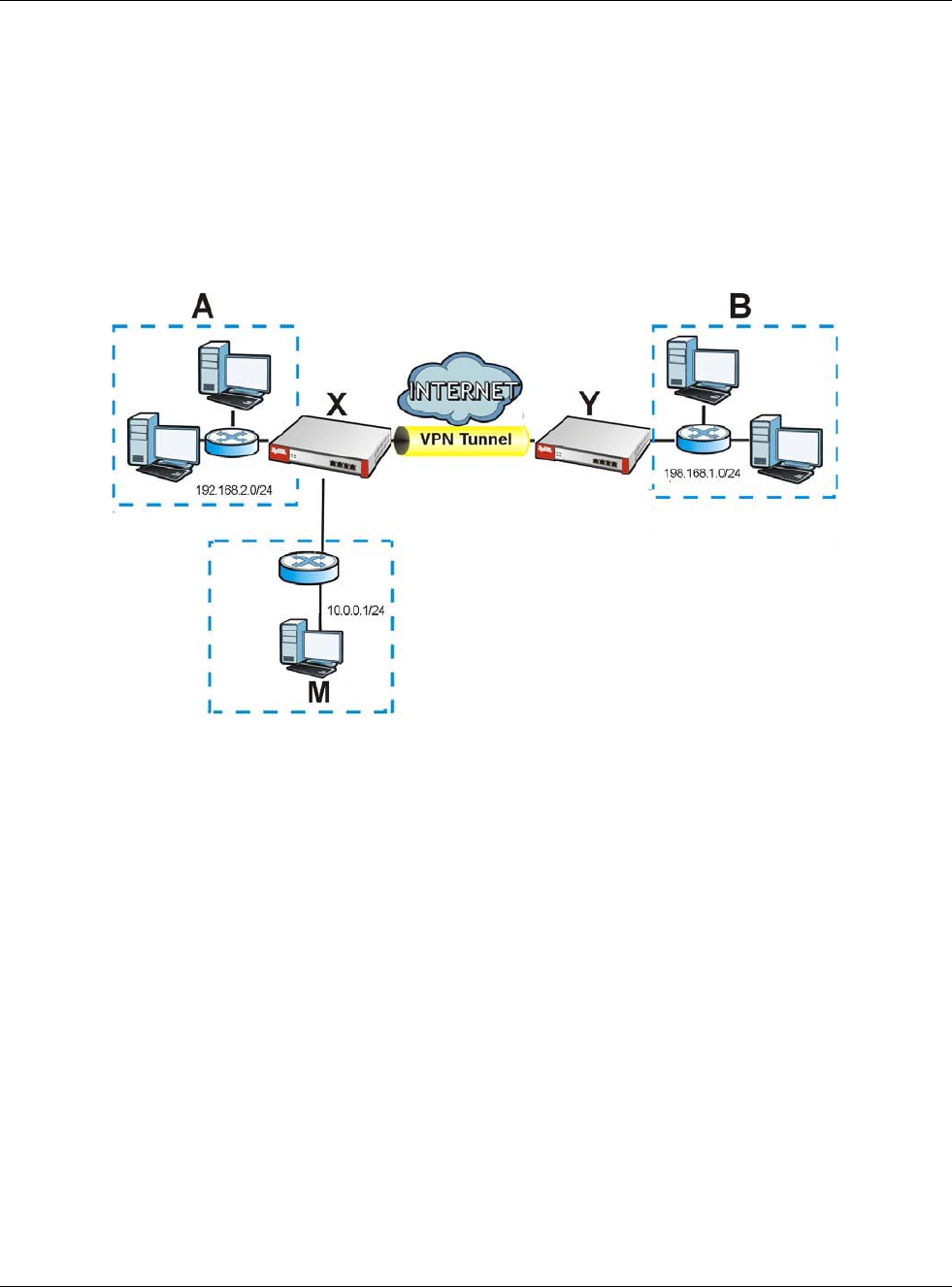
Chapter 21 IPSec VPN
USG20(W)-VPN Series User’s Guide
365
• Source address in outbound packets - this translation is necessary if you want the USG to route
packets from computers outside the local network through the IPSec SA.
• Source address in inbound packets - this translation hides the source address of computers in the
remote network.
• Destination address in inbound packets - this translation is used if you want to forward packets
(for example, mail) from the remote network to a specific computer (like the mail server) in the
local network.
Each kind of translation is explained below. The following example is used to help explain each one.
Figure 238 VPN Example: NAT for Inbound and Outbound Traffic
Source Address in Outbound Packets (Outbound Traffic, Source NAT)
This translation lets the USG route packets from computers that are not part of the specified local
network (local policy) through the IPSec SA. For example, in Figure 238 on page 365, you have to
configure this kind of translation if you want computer M to establish a connection with any
computer in the remote network (B). If you do not configure it, the remote IPSec router may not
route messages for computer M through the IPSec SA because computer M’s IP address is not part
of its local policy.
To set up this NAT, you have to specify the following information:
• Source - the original source address; most likely, computer M’s network.
• Destination - the original destination address; the remote network (B).
• SNAT - the translated source address; the local network (A).
Source Address in Inbound Packets (Inbound Traffic, Source NAT)
You can set up this translation if you want to change the source address of computers in the remote
network. To set up this NAT, you have to specify the following information:
• Source - the original source address; the remote network (B).
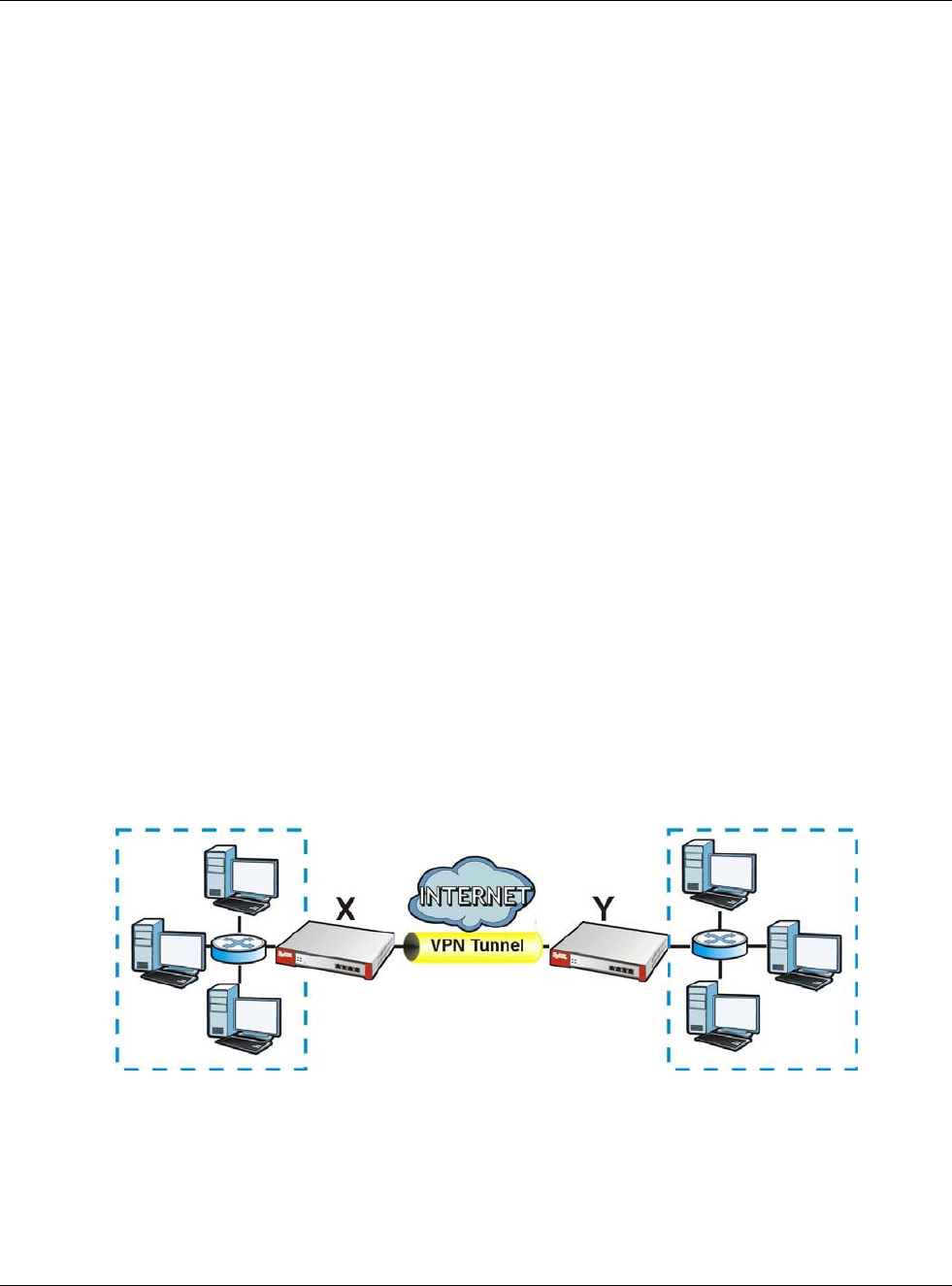
Chapter 21 IPSec VPN
USG20(W)-VPN Series User’s Guide
366
• Destination - the original destination address; the local network (A).
• SNAT - the translated source address; a different IP address (range of addresses) to hide the
original source address.
Destination Address in Inbound Packets (Inbound Traffic, Destination NAT)
You can set up this translation if you want the USG to forward some packets from the remote
network to a specific computer in the local network. For example, in Figure 238 on page 365, you
can configure this kind of translation if you want to forward mail from the remote network to the
mail server in the local network (A).
You have to specify one or more rules when you set up this kind of NAT. The USG checks these rules
similar to the way it checks rules for a security policy. The first part of these rules define the
conditions in which the rule apply.
• Original IP - the original destination address; the remote network (B).
• Protocol - the protocol [TCP, UDP, or both] used by the service requesting the connection.
• Original Port - the original destination port or range of destination ports; in Figure 238 on page
365, it might be port 25 for SMTP.
The second part of these rules controls the translation when the condition is satisfied.
• Mapped IP - the translated destination address; in Figure 238 on page 365, the IP address of the
mail server in the local network (A).
• Mapped Port - the translated destination port or range of destination ports.
The original port range and the mapped port range must be the same size.
IPSec VPN Example Scenario
Here is an example site-to-site IPSec VPN scenario.
Figure 239 Site-to-site IPSec VPN Example
192.168.1.0/24 172.16.1.0/24
1.2.3.4 2.2.2.2
LAN
LAN

USG20(W)-VPN Series User’s Guide
367
CHAPTER 22
SSL VPN
22.1 Overview
Use SSL VPN to allow users to use a web browser for secure remote user login. The remote users
do not need a VPN router or VPN client software.
22.1.1 What You Can Do in this Chapter
•Use the VPN > SSL VPN > Access Privilege screens (see Section 22.2 on page 368) to
configure SSL access policies.
• Use the Click VPN > SSL VPN > Global Setting screen (see Section 22.3 on page 372) to set
the IP address of the USG (or a gateway device) on your network for full tunnel mode access,
enter access messages or upload a custom logo to be displayed on the remote user screen.
•Use the VPN > SSL VPN > SecuExtender screen ( see Section 22.4 on page 374) to update
and check the current and latest version of the Security Extender.
22.1.2 What You Need to Know
Full Tunnel Mode
In full tunnel mode, a virtual connection is created for remote users with private IP addresses in the
same subnet as the local network. This allows them to access network resources in the same way
as if they were part of the internal network.
Figure 240 Network Access Mode: Full Tunnel Mode
SSL Access Policy
An SSL access policy allows the USG to perform the following tasks:
• limit user access to specific applications or file sharing server on the network.
• allow user access to specific networks.
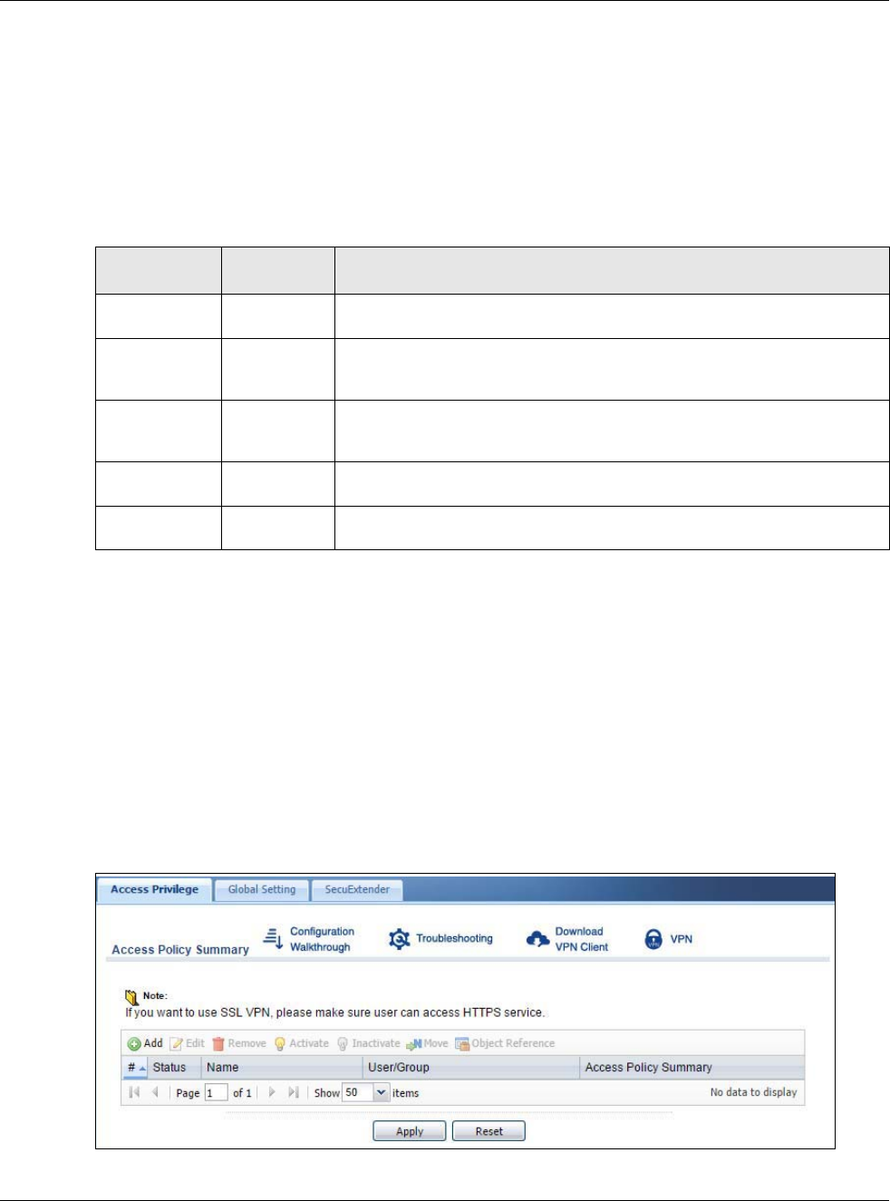
Chapter 22 SSL VPN
USG20(W)-VPN Series User’s Guide
368
• assign private IP addresses and provide DNS/WINS server information to remote users to access
internal networks.
SSL Access Policy Objects
The SSL access policies reference the following objects. If you update this information, in response
to changes, the USG automatically propagates the changes through the SSL policies that use the
object(s). When you delete an SSL policy, the objects are not removed.
You cannot delete an object that is referenced by an SSL access policy. To delete the object, you
must first unassociate the object from the SSL access policy.
22.2 The SSL Access Privilege Screen
Click VPN > SSL VPN to open the Access Privilege screen. This screen lists the configured SSL
access policies.
Click on the icons to go to the OneSecurity.com website where there is guidance on configuration
walkthroughs, troubleshooting and other information.
Figure 241 VPN > SSL VPN > Access Privilege
Table 143 Objects
OBJECT TYPE OBJECT
SCREEN DESCRIPTION
User Accounts User Account/
User Group
Configure a user account or user group to which you want to apply this SSL
access policy.
Application SSL
Application
Configure an SSL application object to specify the type of application and
the address of the local computer, server, or web site SSL users are to be
able to access.
IP Pool Address Configure an address object that defines a range of private IP addresses to
assign to user computers so they can access the internal network through a
VPN connection.
Server
Addresses
Address Configure address objects for the IP addresses of the DNS and WINS
servers that the USG sends to the VPN connection users.
VPN Network Address Configure an address object to specify which network segment users are
allowed to access through a VPN connection.
Chapter 22 SSL VPN
USG20(W)-VPN Series User’s Guide
369
The following table describes the labels in this screen.
22.2.1 The SSL Access Privilege Policy Add/Edit Screen
To create a new or edit an existing SSL access policy, click the Add or Edit icon in the Access
Privilege screen.
Table 144 VPN > SSL VPN > Access Privilege
LABEL DESCRIPTION
Access Policy
Summary
This screen shows a summary of SSL VPN policies created.
Click on the VPN icon to go to the ZyXEL VPN Client product page at the ZyXEL website.
Add Click this to create a new entry. Select an entry and click Add to create a new entry after the
selected entry.
Edit Double-click an entry or select it and click Edit to open a screen where you can modify the
entry’s settings.
Remove To remove an entry, select it and click Remove. The USG confirms you want to remove it
before doing so.
Activate To turn on an entry, select it and click Activate.
Inactivate To turn off an entry, select it and click Inactivate.
Move To move an entry to a different number in the list, click the Move icon. In the field that
appears, specify the number to which you want to move the interface.
Object
References
Select an entry and click Object References to open a screen that shows which settings use
the entry. Click Refresh to update information on this screen.
# This field displays the index number of the entry.
Status This icon is lit when the entry is active and dimmed when the entry is inactive.
Name This field displays the descriptive name of the SSL access policy for identification purposes.
User/Group This field displays the user account or user group name(s) associated to an SSL access policy.
This field displays up to three names.
Access Policy
Summary
This field displays details about the SSL application object this policy uses including its name,
type, and address.
Apply Click Apply to save the settings.
Reset Click Reset to discard all changes.
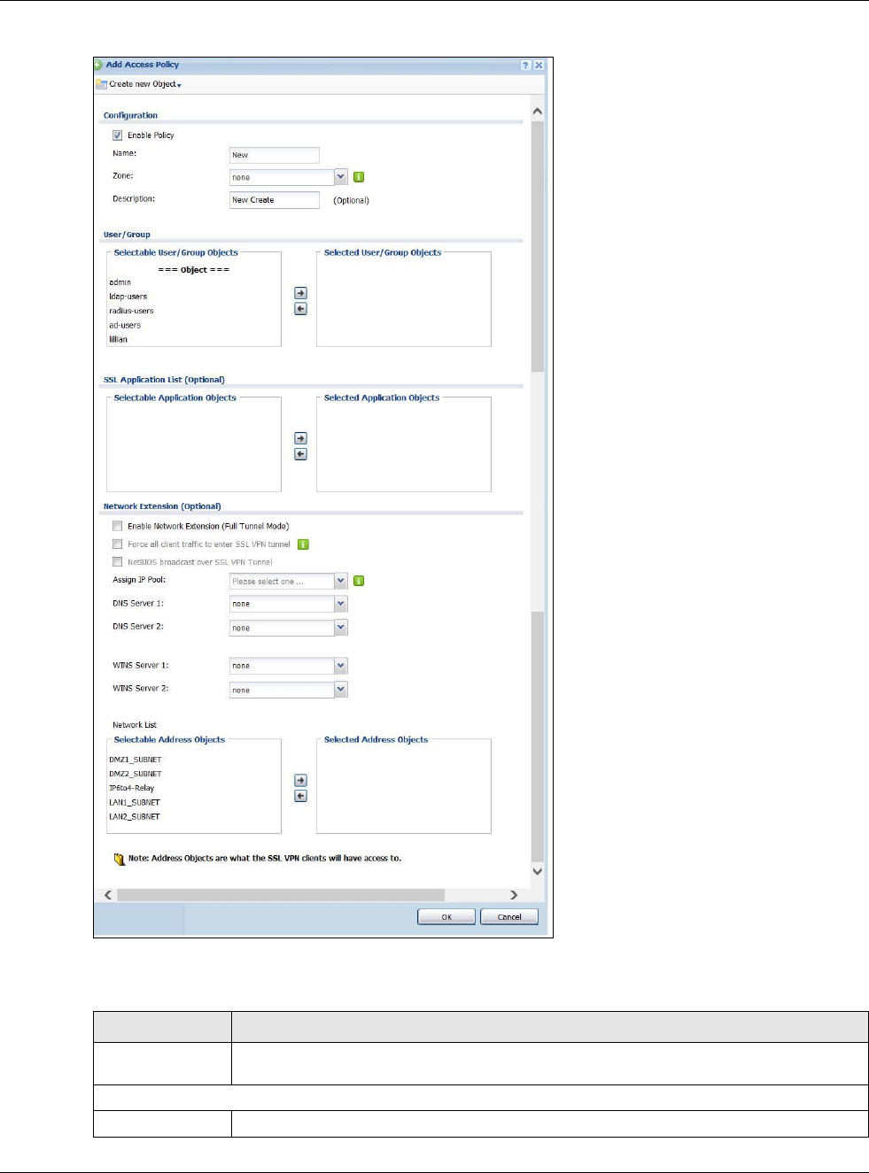
Chapter 22 SSL VPN
USG20(W)-VPN Series User’s Guide
370
Figure 242 VPN > SSL VPN > Add/Edit
The following table describes the labels in this screen.
Table 145 VPN > SSL VPN > Access Privilege > Add/Edit
LABEL DESCRIPTION
Create new
Object
Use to configure any new settings objects that you need to use in this screen.
Configuration
Enable Policy Select this option to activate this SSL access policy.
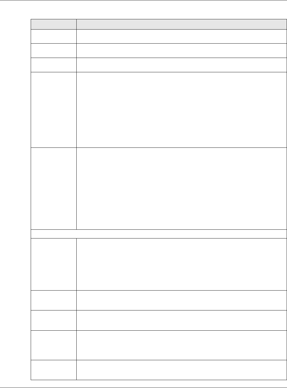
Chapter 22 SSL VPN
USG20(W)-VPN Series User’s Guide
371
Name Enter a descriptive name to identify this policy. You can enter up to 31 characters (“a-z”,
A-Z”, “0-9”) with no spaces allowed.
Zone Select the zone to which to add this SSL access policy. You use zones to apply security
settings such as security policy and remote management.
Description Enter additional information about this SSL access policy. You can enter up to 60
characters ("0-9", "a-z", "A-Z", "-" and "_").
User/Group The Selectable User/Group Objects list displays the name(s) of the user account and/
or user group(s) to which you have not applied an SSL access policy yet.
To associate a user or user group to this SSL access policy, select a user account or user
group and click the right arrow button to add to the Selected User/Group Objects list.
You can select more than one name.
To remove a user or user group, select the name(s) in the Selected User/Group
Objects list and click the left arrow button.
Note: Although you can select admin and limited-admin accounts in this screen, they are
reserved for device configuration only. You cannot use them to access the SSL VPN
portal.
SSL Application
List (Optional)
The Selectable Application Objects list displays the name(s) of the SSL application(s)
you can select for this SSL access policy.
To associate an SSL application to this SSL access policy, select a name and click the right
arrow button to add to the Selected Application Objects list. You can select more than
one application.
To remove an SSL application, select the name(s) in the Selected Application Objects
list and click the left arrow button.
Note: To allow access to shared files on a Windows 7 computer, within Windows 7 you must
enable sharing on the folder and also go to the Network and Sharing Center’s
Advanced sharing settings and turn on the current network profile’s file and printer
sharing.
Network Extension (Optional)
Enable Network
Extension
Select this option to create a VPN tunnel between the authenticated users and the internal
network. This allows the users to access the resources on the network as if they were on
the same local network. This includes access to resources not supported by SSL
application objects. For example this lets users Telnet to the internal network even though
the USG does not have SSL application objects for Telnet.
Clear this option to disable this feature. Users can only access the applications as defined
by the VPN tunnel’s selected SSL application settings and the remote user computers are
not made to be a part of the local network.
Force all client
traffic to SSL VPN
tunnel
Select this to send all traffic from the SSL VPN clients through the SSL VPN tunnel. This
replaces the default gateway of the SSL VPN clients with the SSL VPN gateway.
NetBIOS
broadcast over
SSL VPN Tunnel
Select this to search for a remote computer and access its applications as if it was in a
Local Area Network. The user can find a computer not only by its IP adress but also by
computer name.
Assign IP Pool Define a separate pool of IP addresses to assign to the SSL users. Select it here.
The SSL VPN IP pool should not overlap with IP addresses on the USG's local networks
(LAN and DMZ for example), the SSL user's network, or the networks you specify in the
SSL VPN Network List.
DNS/WINS
Server 1..2
Select the name of the DNS or WINS server whose information the USG sends to the
remote users. This allows them to access devices on the local network using domain
names instead of IP addresses.
Table 145 VPN > SSL VPN > Access Privilege > Add/Edit (continued)
LABEL DESCRIPTION
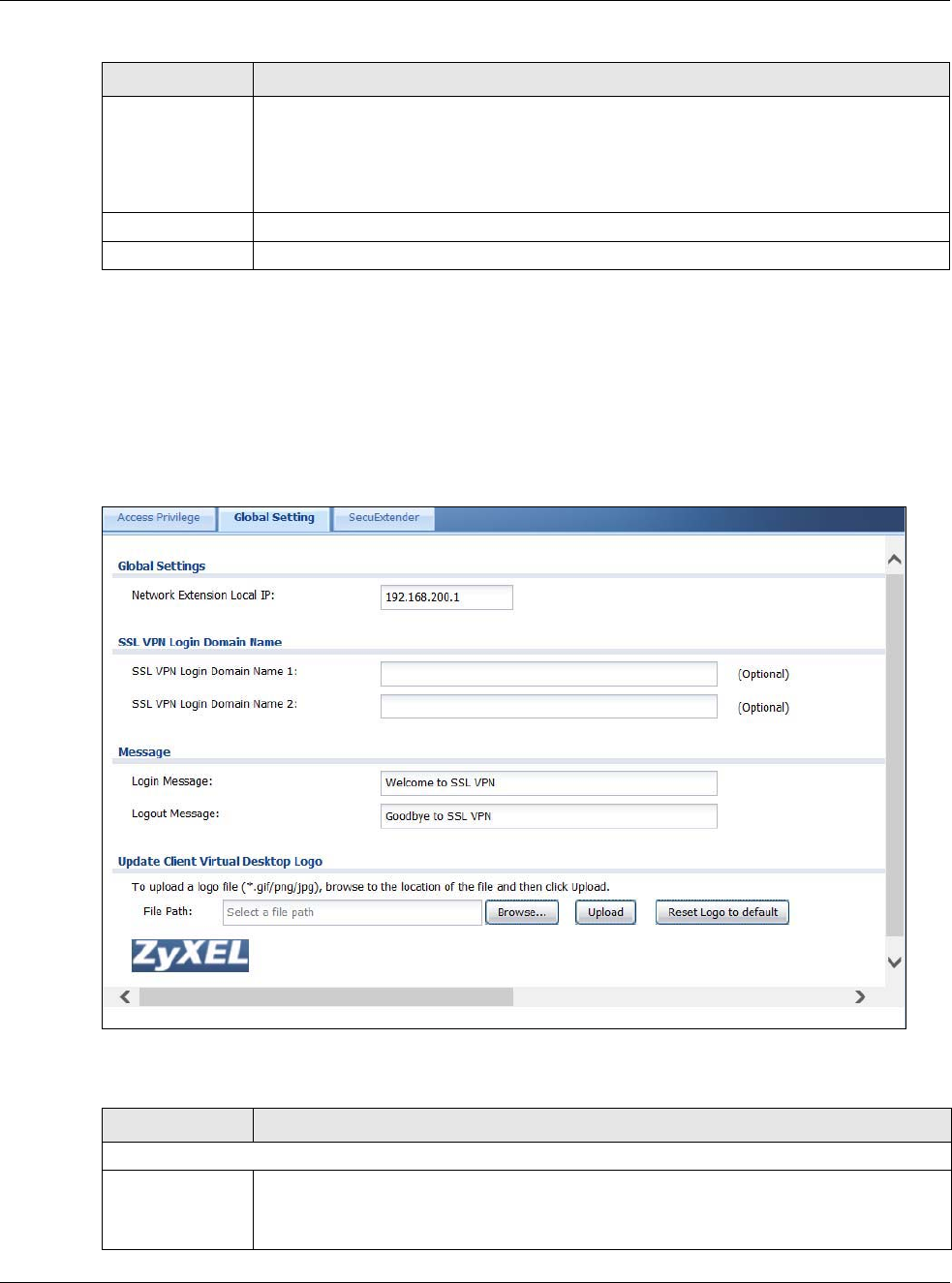
Chapter 22 SSL VPN
USG20(W)-VPN Series User’s Guide
372
22.3 The SSL Global Setting Screen
Click VPN > SSL VPN and click the Global Setting tab to display the following screen. Use this
screen to set the IP address of the USG (or a gateway device) on your network for full tunnel mode
access, enter access messages or upload a custom logo to be displayed on the remote user screen.
Figure 243 VPN > SSL VPN > Global Setting
The following table describes the labels in this screen.
Network List To allow user access to local network(s), select a network name in the Selectable
Address Objects list and click the right arrow button to add to the Selected Address
Objects list. You can select more than one network.
To block access to a network, select the network name in the Selected Address Objects
list and click the left arrow button.
OK Click OK to save the changes and return to the main Access Privilege screen.
Cancel Click Cancel to discard all changes and return to the main Access Privilege screen.
Table 145 VPN > SSL VPN > Access Privilege > Add/Edit (continued)
LABEL DESCRIPTION
Table 146 VPN > SSL VPN > Global Setting
LABEL DESCRIPTION
Global Setting
Network
Extension Local
IP
Specify the IP address of the USG (or a gateway device) for full tunnel mode SSL VPN
access.
Leave this field to the default settings unless it conflicts with another interface.
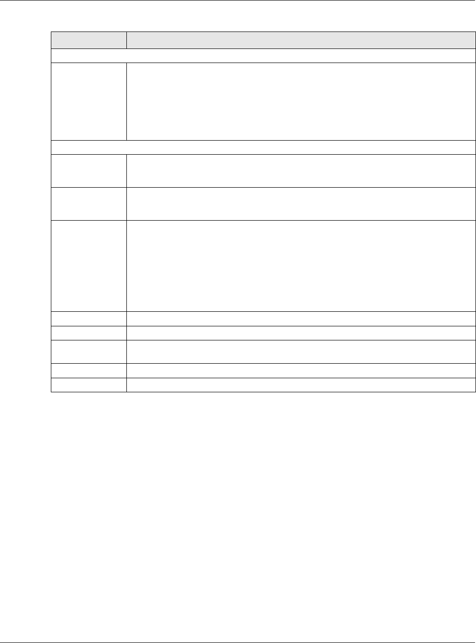
Chapter 22 SSL VPN
USG20(W)-VPN Series User’s Guide
373
22.3.1 How to Upload a Custom Logo
Follow the steps below to upload a custom logo to display on the remote user SSL VPN screens.
1Click VPN > SSL VPN and click the Global Setting tab to display the configuration screen.
2Click Browse to locate the logo graphic. Make sure the file is in GIF, JPG, or PNG format.
3Click Apply to start the file transfer process.
4Log in as a user to verify that the new logo displays properly.
The following shows an example logo on the remote user screen.
SSL VPN Login Domain Name
SSL VPN Login
Domain Name 1/
2
Specify a full domain name for users to use for SSL VPN login. The domain name must be
registered to one of the USG’s IP addresses or be one of the USG’s DDNS entries. You can
specify up to two domain names so you could use one domain name for each of two WAN
ports. For example, www.zyxel.com is a fully qualified domain name where “www” is the
host.
The USG displays the normal login screen without the button for logging into the Web
Configurator.
Message
Login Message Specify a message to display on the screen when a user logs in and an SSL VPN
connection is established successfully. You can enter up to 60 characters (0-9, a-z, A-Z,
'()+,/:=?;!*#@$_%-") with spaces allowed.
Logout Message Specify a message to display on the screen when a user logs out and the SSL VPN
connection is terminated successfully. You can enter up to 60 characters (0-9, a-z, A-Z,
'()+,/:=?;!*#@$_%-") with spaces allowed.
Update Client
Virtual Desktop
Logo
You can upload a graphic logo to be displayed on the web browser on the remote user
computer. The ZyXEL company logo is the default logo.
Specify the location and file name of the logo graphic or click Browse to locate it.
Note: The logo graphic must be GIF, JPG, or PNG format. The graphic should use a
resolution of 103 x 29 pixels to avoid distortion when displayed. The USG
automatically resizes a graphic of a different resolution to 103 x 29 pixels. The file
size must be 100 kilobytes or less. Transparent background is recommended.
Browse Click Browse to locate the graphic file on your computer.
Upload Click Upload to transfer the specified graphic file from your computer to the USG.
Reset Logo to
Default
Click Reset Logo to Default to display the ZyXEL company logo on the remote user’s
web browser.
Apply Click Apply to save the changes and/or start the logo file upload process.
Reset Click Reset to return the screen to its last-saved settings.
Table 146 VPN > SSL VPN > Global Setting (continued)
LABEL DESCRIPTION
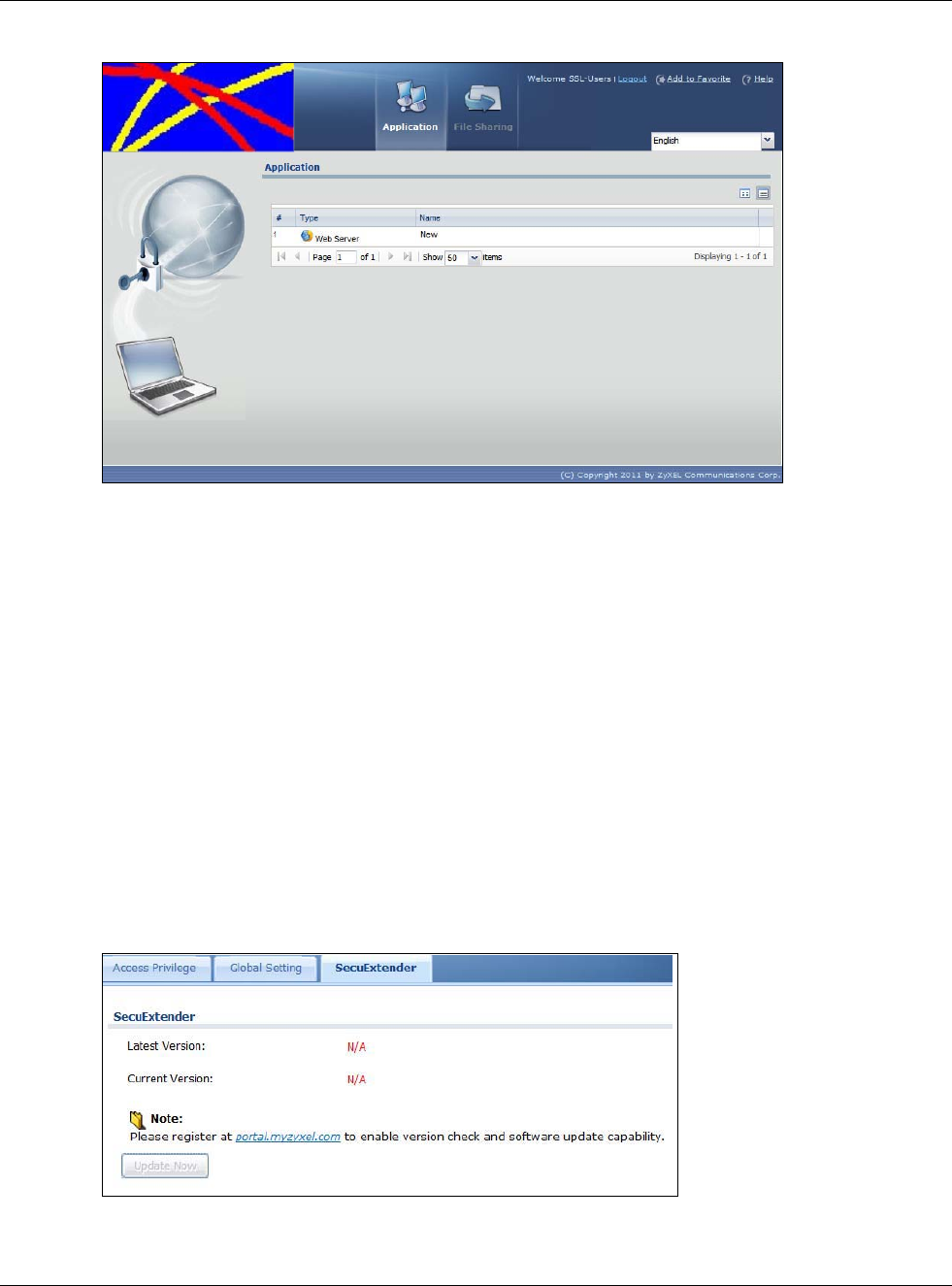
Chapter 22 SSL VPN
USG20(W)-VPN Series User’s Guide
374
Figure 244 Example Logo Graphic Display
22.4 USG SecuExtender
The USG automatically loads the USG SecuExtender client program to your computer after a
successful login to an SSL VPN tunnel with network extension support enabled. The USG
SecuExtender lets you:
• Access servers, remote desktops and manage files as if you were on the local network.
• Use applications like e-mail, file transfer, and remote desktop programs directly without using a
browser. For example, you can use Outlook for e-mail instead of the USG’s web-based e-mail.
• Use applications, even proprietary applications, for which the USG does not offer SSL application
objects.
The applications must be installed on your computer. For example, to use the VNC remote desktop
program, you must have the VNC client installed on your computer. Please refer to the
SecuExtender chapter for details.
Figure 245 Configuration > VPN > SSL VPN > SecuExtender.
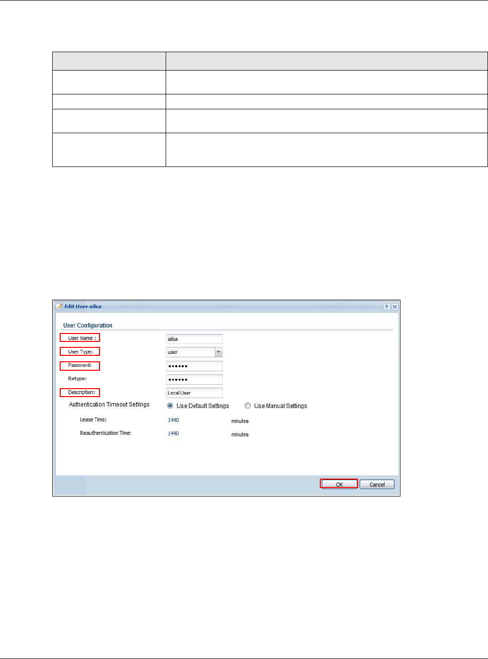
Chapter 22 SSL VPN
USG20(W)-VPN Series User’s Guide
375
The following table describes the labels in this screen.
22.4.1 Example: Configure USG for SecuExtender
Make these configurations on the USG to allow the remote user to access resources behind the USG
using SecuExtender. These steps can be performed in any order.
1Create a user that can log into the USG. Using the USG web configurator, go to Configuration >
Object > User > Add and substitute your information for the information shown in the following
example.
Figure 246 Create a User
2Next create an SSL VPN Access Privilege policy substituting your information for the information
shown in the following example. Using the USG web configurator, go to Configuration > VPN >
SSL VPN > Access Privilege > Add.
Table 147 Configuration > VPN > SSL VPN > SecuExtender
LABEL DESCRIPTION
Latest Version This displays the latest version of the USG Security SecuExtender that is
available.
Current Version This displays the current version of SecuExtender that is installed in the USG.
Note: You need to register first at portal.myzyxel.com to download the latest version of
SecuExtender.
Update Now The USG periodically checks if there’s a later version of SecuExtender at the
portal. The Update Now button is enabled when thre is.Click Update Now to
get the latest version of SecuExtender.
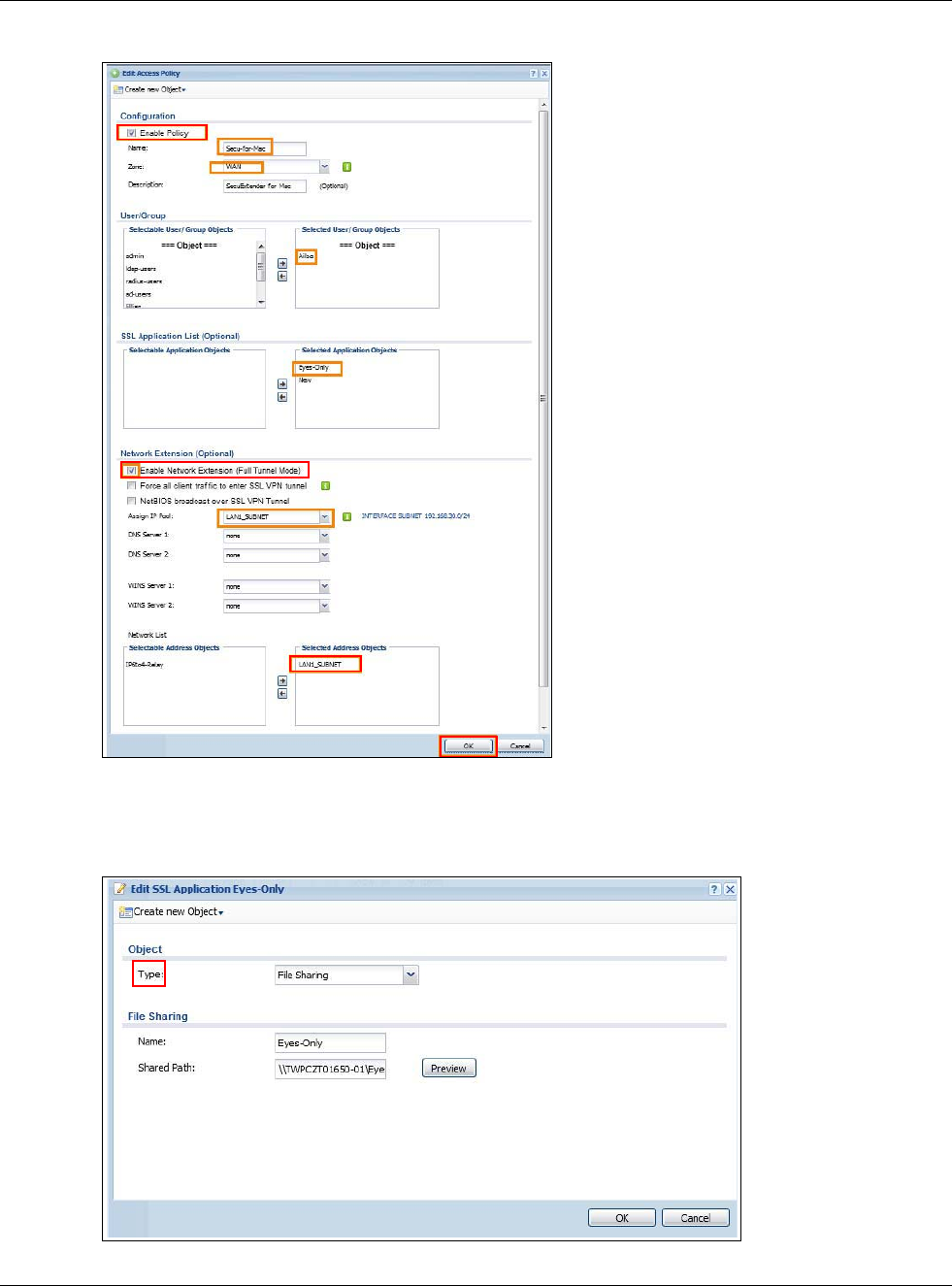
Chapter 22 SSL VPN
USG20(W)-VPN Series User’s Guide
376
Figure 247 Create an SSL VPN Access Privilege Policy
3Then create File Sharing and Web Application SSL Application objects. Using the USG web
configurator, go to Configuration > Object > SSL Application > Add and select the Type
accordingly. Substitute your information for the information shown in the following example.
Figure 248 Create a File Sharing SSL Application Object
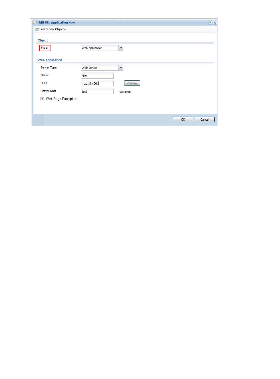
Chapter 22 SSL VPN
USG20(W)-VPN Series User’s Guide
377
Create a Web Application SSL Application Object
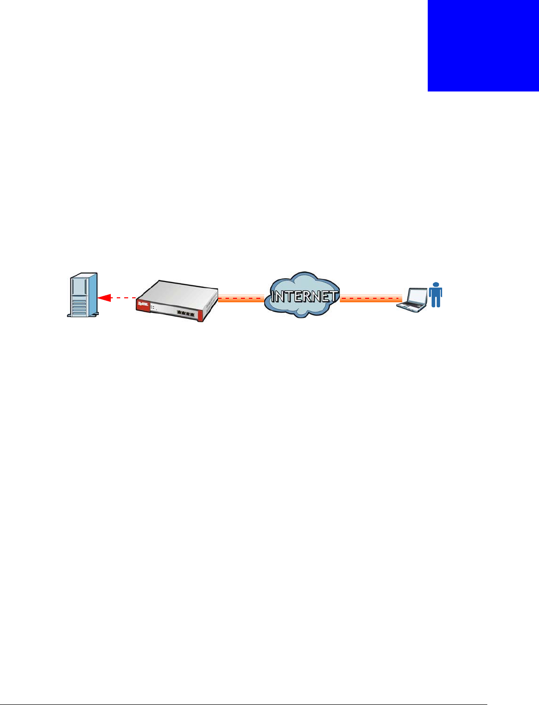
USG20(W)-VPN Series User’s Guide
378
CHAPTER 23
SSL User Screens
23.1 Overview
This chapter introduces the remote user SSL VPN screens. The following figure shows a network
example where a remote user (A) logs into the USG from the Internet to access the web server
(WWW) on the local network.
Figure 249 Network Example
23.1.1 What You Need to Know
The USG can use SSL VPN to provide secure connections to network resources such as applications,
files, intranet sites or e-mail through a web-based interface and using Microsoft Outlook Web
Access (OWA).
Network Resource Access Methods
As a remote user, you can access resources on the local network using one of the following
methods.
• Using a supported web browser
Once you have successfully logged in through the USG, you can access intranet sites, web-based
applications, or web-based e-mails using one of the supported web browsers.
• Using the USG SecuExtender client
Once you have successfully logged into the USG, if the SSL VPN access policy has network
extension enabled the USG automatically loads the USG SecuExtender client program to your
computer. With the USG SecuExtender, you can access network resources, remote desktops and
manage files as if you were on the local network. See Chapter 24 on page 391 for more on the
USG SecuExtender.
System Requirements
Here are the browser and computer system requirements for remote user access.
• Windows 7 (32 or 64-bit), Vista (32 or 64-bit), 2003 (32-bit), XP (32-bit), or 2000 (32-bit)
• Internet Explorer 7 and above or Firefox 1.5 and above
A
WWW
Internet
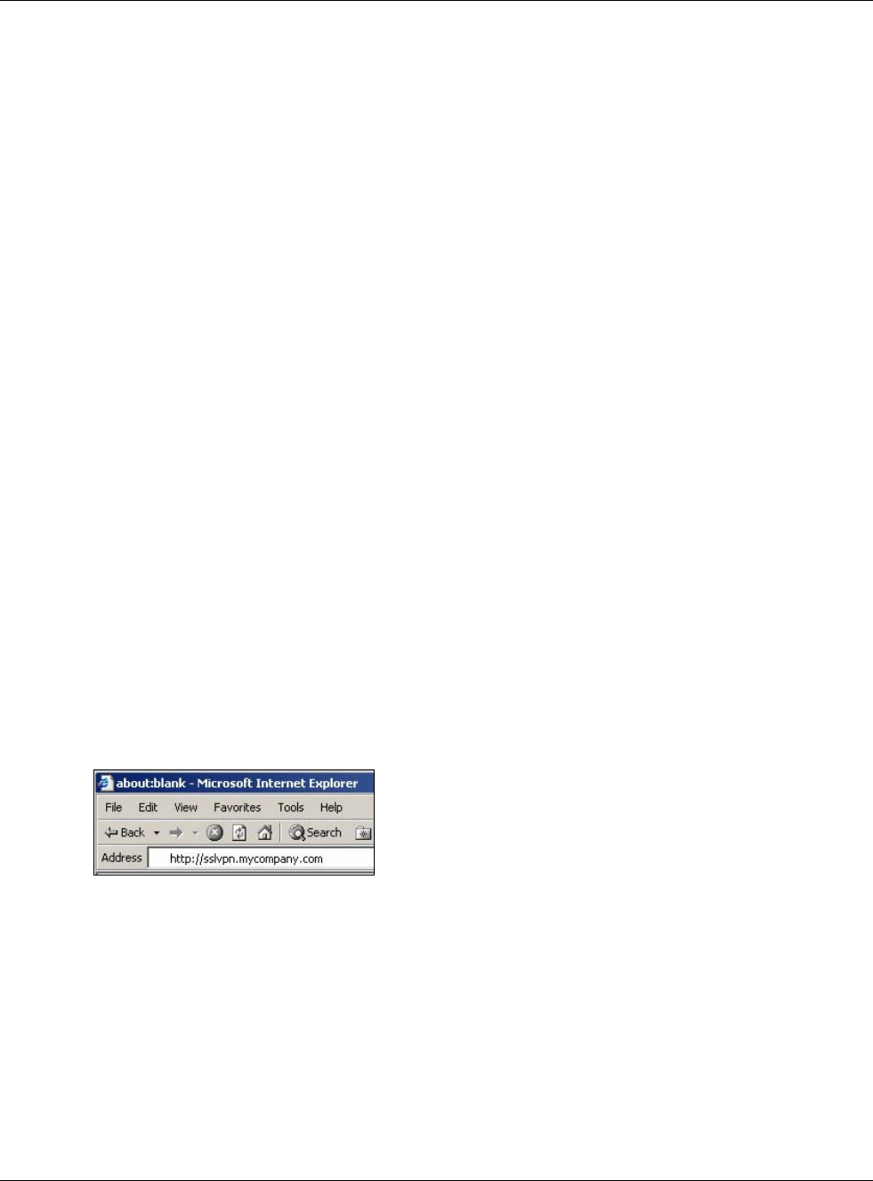
Chapter 23 SSL User Screens
USG20(W)-VPN Series User’s Guide
379
• Using RDP requires Internet Explorer
• Sun’s Runtime Environment (JRE) version 1.6 or later installed and enabled.
Required Information
A remote user needs the following information from the network administrator to log in and access
network resources.
• the domain name or IP address of the USG
• the login account user name and password
• if also required, the user name and/or password to access the network resource
Certificates
The remote user’s computer establishes an HTTPS connection to the USG to access the login
screen. If instructed by your network administrator, you must install or import a certificate
(provided by the USG or your network administrator).
Finding Out More
See Chapter 22 on page 367 for how to configure SSL VPN on the USG.
23.2 Remote SSL User Login
This section shows you how to access and log into the network through the USG. Example screens
for Internet Explorer are shown.
1Open a web browser and enter the web site address or IP address of the USG. For example, “http:/
/sslvpn.mycompany.com”.
Figure 250 Enter the Address in a Web Browser
2Click OK or Yes if a security screen displays.
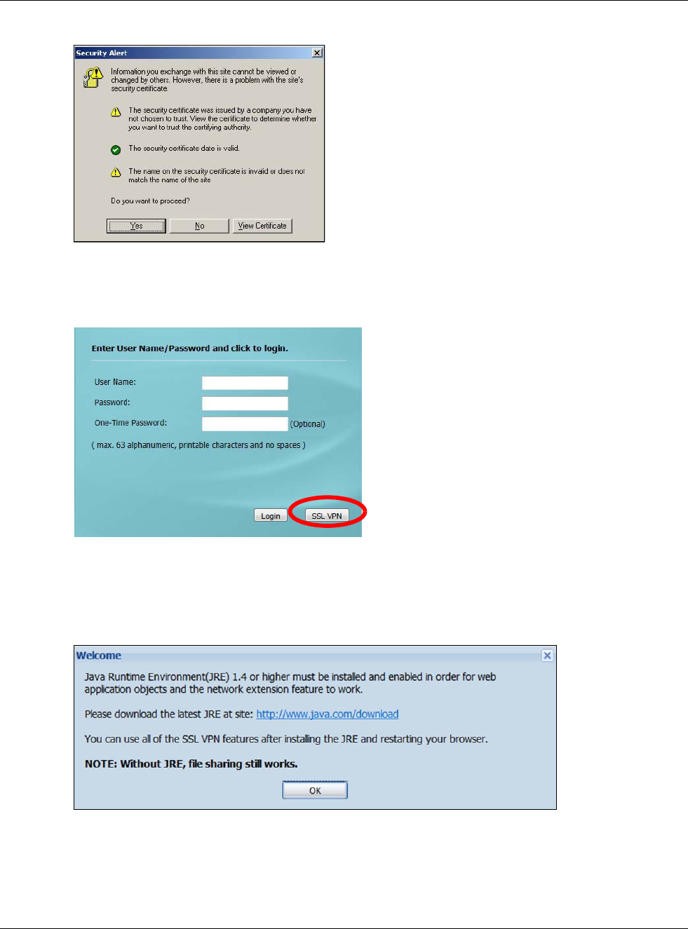
Chapter 23 SSL User Screens
USG20(W)-VPN Series User’s Guide
380
Figure 251 Login Security Screen
3A login screen displays. Enter the user name and password of your login account. If a token
password is also required, enter it in the One-Time Password field. Click SSL VPN to log in and
establish an SSL VPN connection to the network to access network resources.
Figure 252 Login Screen
4Your computer starts establishing a secure connection to the USG after a successful login. This may
take up to two minutes. If you get a message about needing Java, download and install it and
restart your browser and re-login. If a certificate warning screen displays, click OK, Yes or
Continue.
Figure 253 Java Needed Message
5The USG tries to install the SecuExtender client. As shown next, you may have to click some pop-
ups to get your browser to allow the installation.
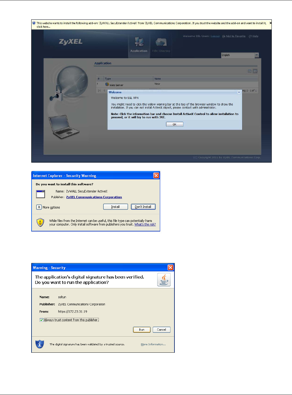
Chapter 23 SSL User Screens
USG20(W)-VPN Series User’s Guide
381
Figure 254 ActiveX Object Installation Blocked by Browser
Figure 255 SecuExtender Blocked by Internet Explorer
6The USG tries to run the “ssltun” application. You may need to click something to get your browser
to allow this. In Internet Explorer, click Run.
Figure 256 SecuExtender Progress
7Click Next to use the setup wizard to install the SecuExtender client on your computer.

Chapter 23 SSL User Screens
USG20(W)-VPN Series User’s Guide
382
Figure 257 SecuExtender Progress
8If a screen like the following displays, click Continue Anyway to finish installing the SecuExtender
client on your computer.
Figure 258 Installation Warning
9The Application screen displays showing the list of resources available to you. See Figure 259 on
page 383 for a screen example.
Note: Available resource links vary depending on the configuration your network
administrator made.
23.3 The SSL VPN User Screens
This section describes the main elements in the remote user screens.
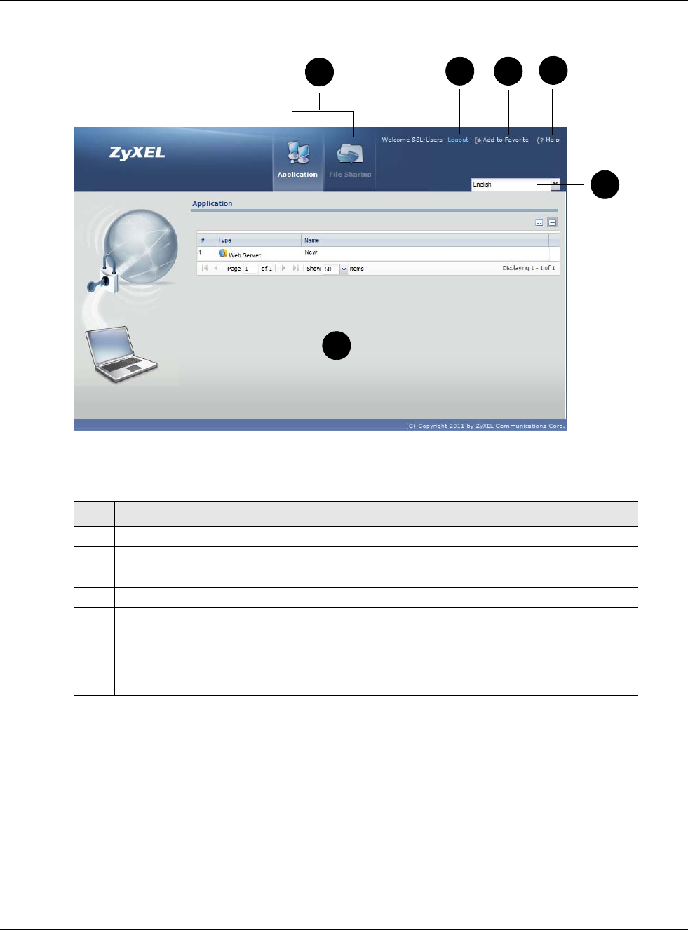
Chapter 23 SSL User Screens
USG20(W)-VPN Series User’s Guide
383
Figure 259 Remote User Screen
The following table describes the various parts of a remote user screen.
23.4 Bookmarking the USG
You can create a bookmark of the USG by clicking the Add to Favorite icon. This allows you to
access the USG using the bookmark without having to enter the address every time.
1In any remote user screen, click the Add to Favorite icon.
2A screen displays. Accept the default name in the Name field or enter a descriptive name to
identify this link.
Table 148 Remote User Screen Overview
#DESCRIPTION
1 Click on a menu tab to go to the Application or File Sharing screen.
2 Click this icon to log out and terminate the secure connection.
3 Click this icon to create a bookmark to the SSL VPN user screen in your web browser.
4 Click this icon to display the on-line help window.
5 Select your preferred language for the interface.
6 This part of the screen displays a list of the resources available to you.
In the Application screen, click on a link to access or display the access method.
In the File Sharing screen, click on a link to open a file or directory.
234
5
1
6
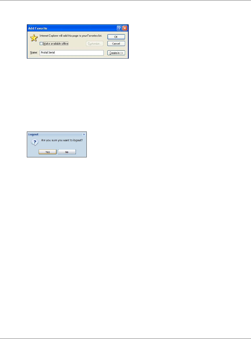
Chapter 23 SSL User Screens
USG20(W)-VPN Series User’s Guide
384
3Click OK to create a bookmark in your web browser.
Figure 260 Add Favorite
23.5 Logging Out of the SSL VPN User Screens
To properly terminate a connection, click on the Logout icon in any remote user screen.
1Click the Logout icon in any remote user screen.
2A prompt window displays. Click OK to continue.
Figure 261 Logout: Prompt
23.6 SSL User Application Screen
Use the Application tab’s screen to access web-based applications (such as web sites and e-mail)
on the network through the SSL VPN connection. Which applications you can access depends on the
USG’s configuration.
The Name field displays the descriptive name for an application. The Type field displays wether the
application is a web site (Web Server) or web-based e-mail using Microsoft Outlook Web Access
(OWA).
To access a web-based application, simply click a link in the Application screen to display the web
screen in a separate browser window.
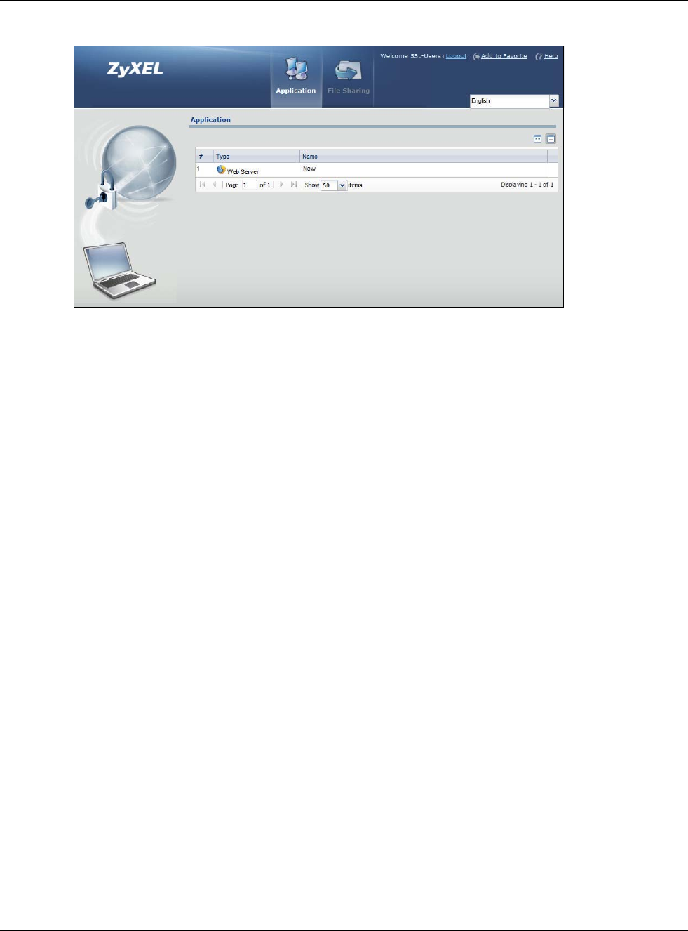
Chapter 23 SSL User Screens
USG20(W)-VPN Series User’s Guide
385
Figure 262 Application
23.7 SSL User File Sharing
The File Sharing screen lets you access files on a file server through the SSL VPN connection. Use
it to display and access shared files/folders on a file server.
You can also perform the following actions:
• Access a folder.
• Open a file (if your web browser cannot open the file, you are prompted to download it).
• Save a file to your computer.
• Create a new folder.
• Rename a file or folder.
• Delete a file or folder.
• Upload a file.
Note: Available actions you can perform in the File Sharing screen vary depending on
the rights granted to you on the file server.
23.7.1 The Main File Sharing Screen
The first File Sharing screen displays the name(s) of the shared folder(s) available. The following
figure shows an example with one file share.
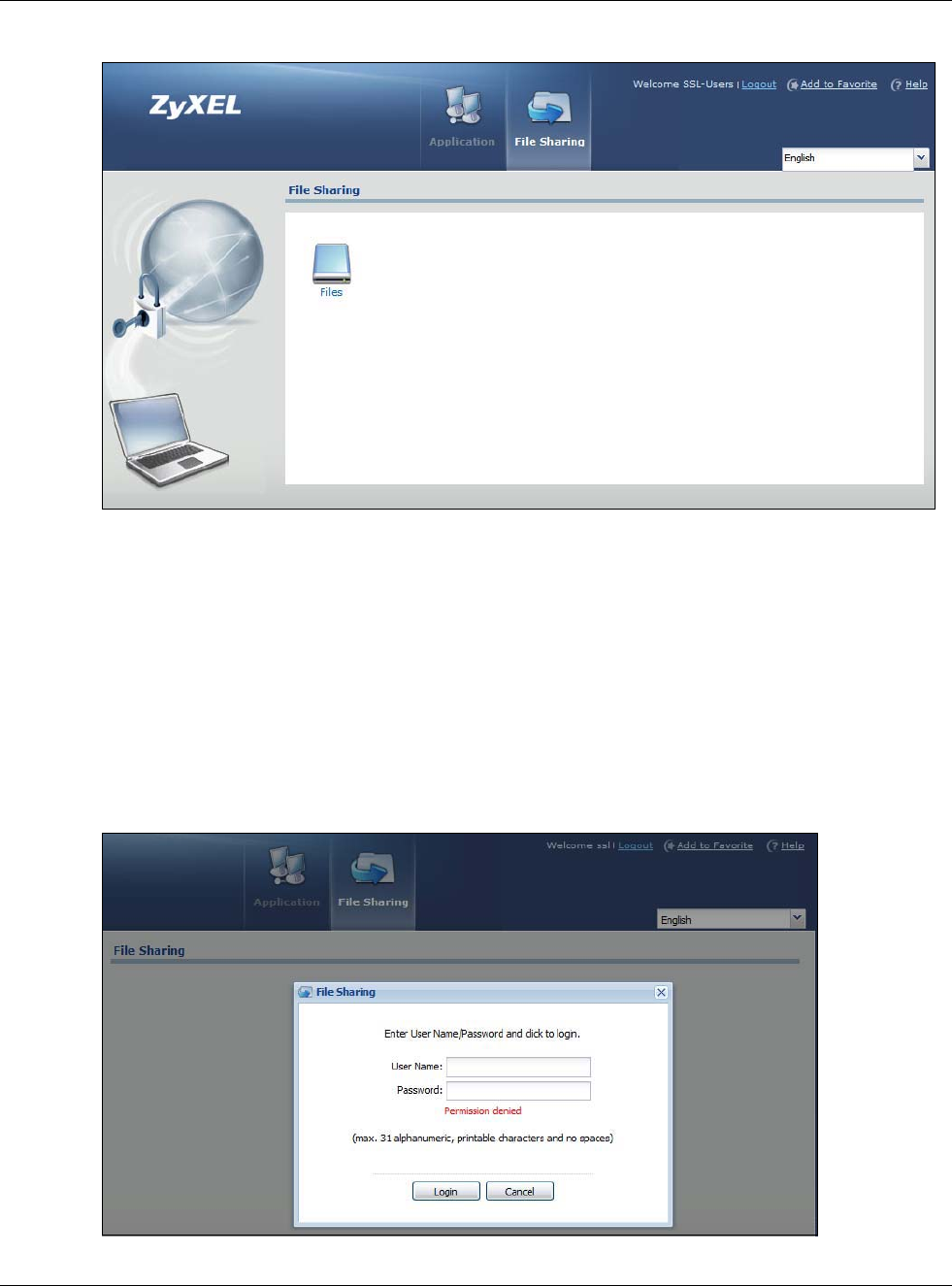
Chapter 23 SSL User Screens
USG20(W)-VPN Series User’s Guide
386
Figure 263 File Sharing
23.7.2 Opening a File or Folder
You can open a file if the file extension is recognized by the web browser and the associated
application is installed on your computer.
1Log in as a remote user and click the File Sharing tab.
2Click on a file share icon.
3If an access user name and password are required, a screen displays as shown in the following
figure. Enter the account information and click Login to continue.
Figure 264 File Sharing: Enter Access User Name and Password
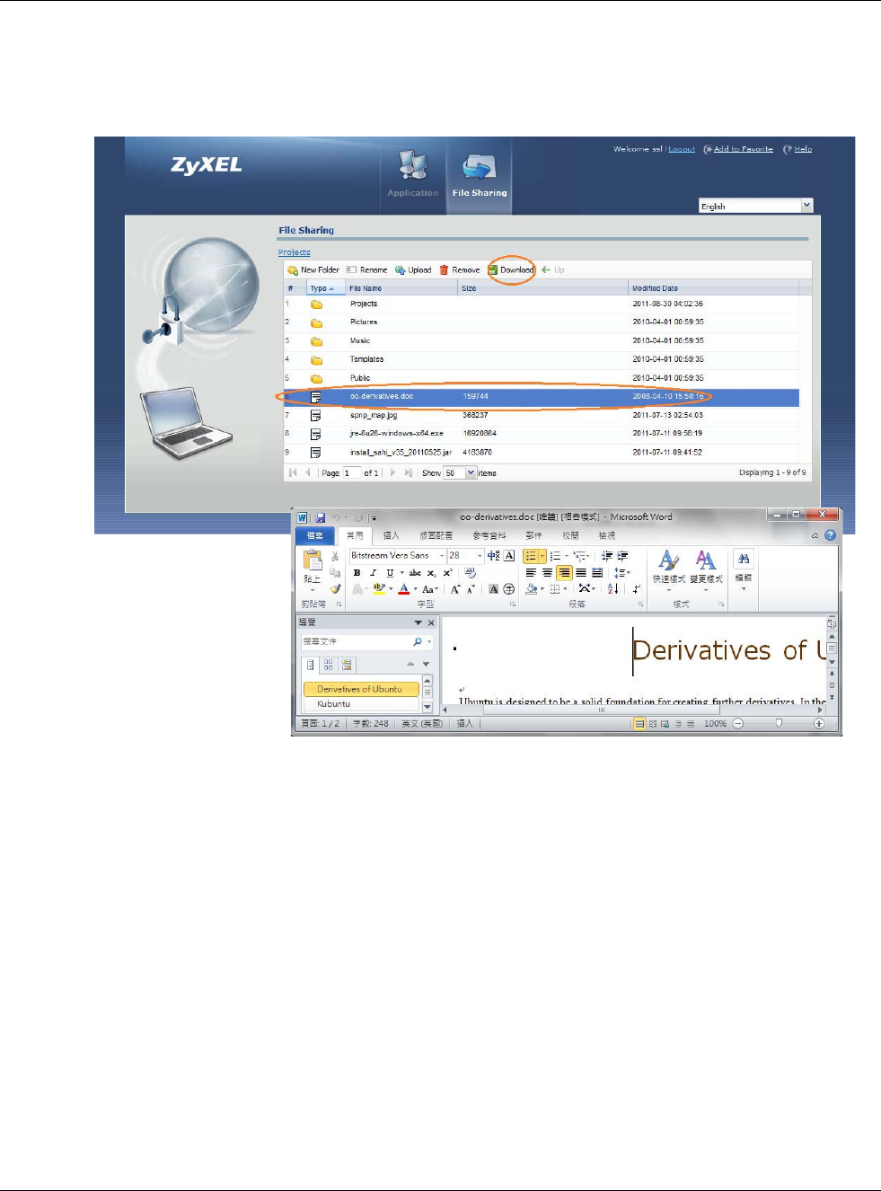
Chapter 23 SSL User Screens
USG20(W)-VPN Series User’s Guide
387
4A list of files/folders displays. Double click a file to open it in a separate browser window or select a
file and click Download to save it to your computer. You can also click a folder to access it.
For this example, click on a .doc file to open the Word document.
Figure 265 File Sharing: Open a Word File
23.7.3 Downloading a File
You are prompted to download a file which cannot be opened using a web browser.
Follow the on-screen instructions to download and save the file to your computer. Then launch the
associated application to open the file.
23.7.4 Saving a File
After you have opened a file in a web browser, you can save a copy of the file by clicking File >
Save As and following the on-screen instructions.
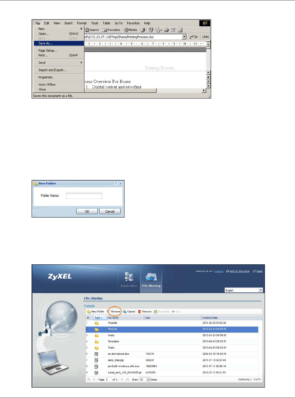
Chapter 23 SSL User Screens
USG20(W)-VPN Series User’s Guide
388
Figure 266 File Sharing: Save a Word File
23.7.5 Creating a New Folder
To create a new folder in the file share location, click the New Folder icon.
Specify a descriptive name for the folder. You can enter up to 356 characters. Then click Add.
Note: Make sure the length of the folder name does not exceed the maximum allowed on
the file server.
Figure 267 File Sharing: Create a New Folder
23.7.6 Renaming a File or Folder
To rename a file or folder, select a file or folder and click the Rename icon.
Figure 268 File Sharing: Rename
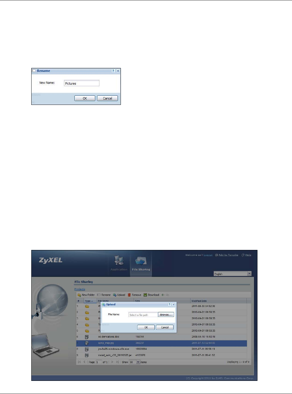
Chapter 23 SSL User Screens
USG20(W)-VPN Series User’s Guide
389
A popup window displays. Specify the new name and/or file extension in the field provided. You can
enter up to 356 characters. Then click Apply.
Note: Make sure the length of the name does not exceed the maximum allowed on the
file server.
You may not be able to open a file if you change the file extension.
Figure 269 File Sharing: Rename
23.7.7 Deleting a File or Folder
Click the Delete icon next to a file or folder to remove it.
23.7.8 Uploading a File
Follow the steps below to upload a file to the file server.
1Log into the remote user screen and click the File Sharing tab.
2Click Upload and specify the location and/or name of the file you want to upload. Or click Browse
to locate it.
3Click OK to send the file to the file server.
4After the file is uploaded successfully, you should see the name of the file and a message in the
screen.
Figure 270 File Sharing: File Upload

Chapter 23 SSL User Screens
USG20(W)-VPN Series User’s Guide
390
Note: Uploading a file with the same name and file extension replaces the existing file on
the file server. No warning message is displayed.