ZyXEL Communications USG20W-VPN VPN Firewall User Manual Book
ZyXEL Communications Corporation VPN Firewall Book
Contents
- 1. Users Manual Part 1
- 2. Users Manual Part 2
- 3. Users Manual Part 3
- 4. Users Manual Part 4
- 5. Users Manual Part 5
Users Manual Part 1
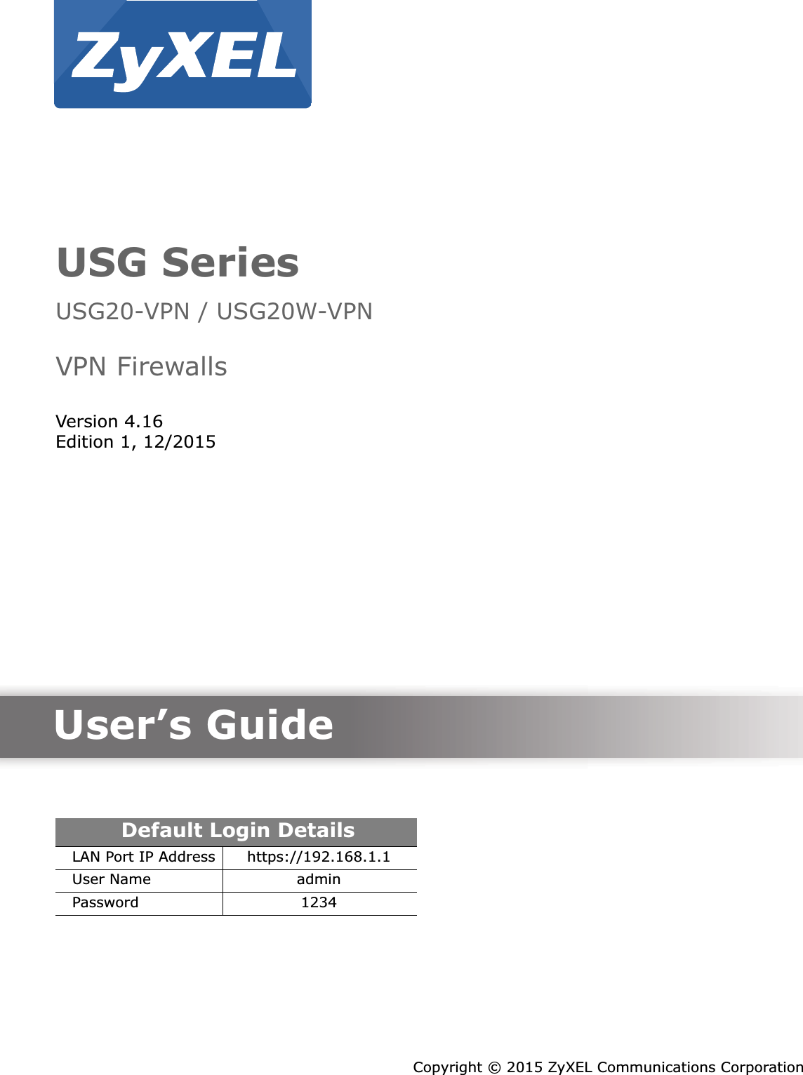
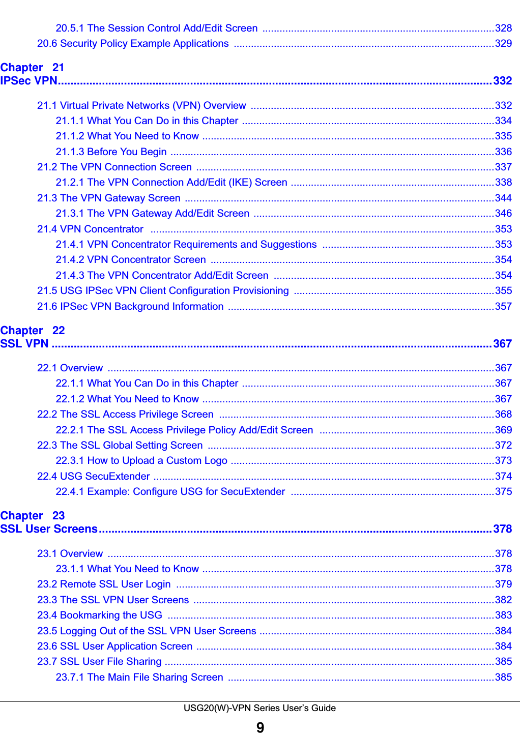


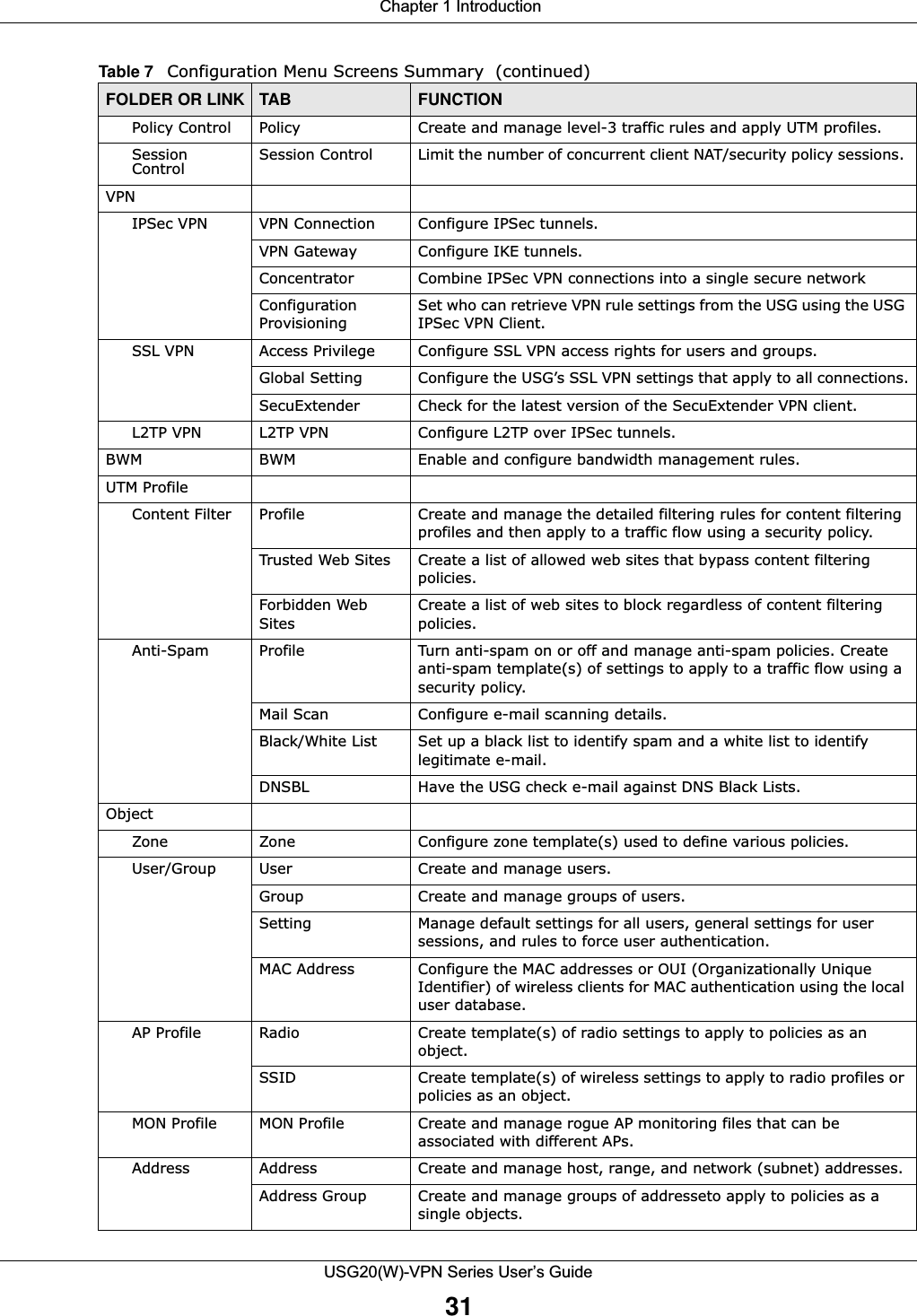
![Chapter 1 IntroductionUSG20(W)-VPN Series User’s Guide34Figure 16 Common Table Column OptionsSelect a column heading cell’s right border and drag to re-size the column.Figure 17 Resizing a Table ColumnSelect a column heading and drag and drop it to change the column order. A green check mark displays next to the column’s title when you drag the column to a valid new location.Figure 18 Moving ColumnsUse the icons and fields at the bottom of the table to navigate to different pages of entries and control how many entries display at a time.Figure 19 Navigating Pages of Table EntriesThe tables have icons for working with table entries. You can often use the [Shift] or [Ctrl] key to select multiple entries to remove, activate, or deactivate.](https://usermanual.wiki/ZyXEL-Communications/USG20W-VPN.Users-Manual-Part-1/User-Guide-2904713-Page-34.png)
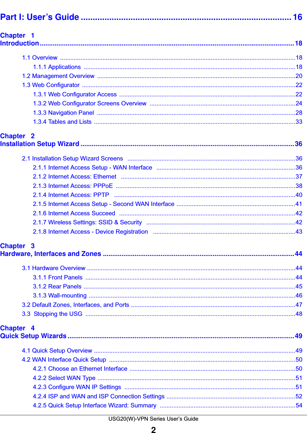
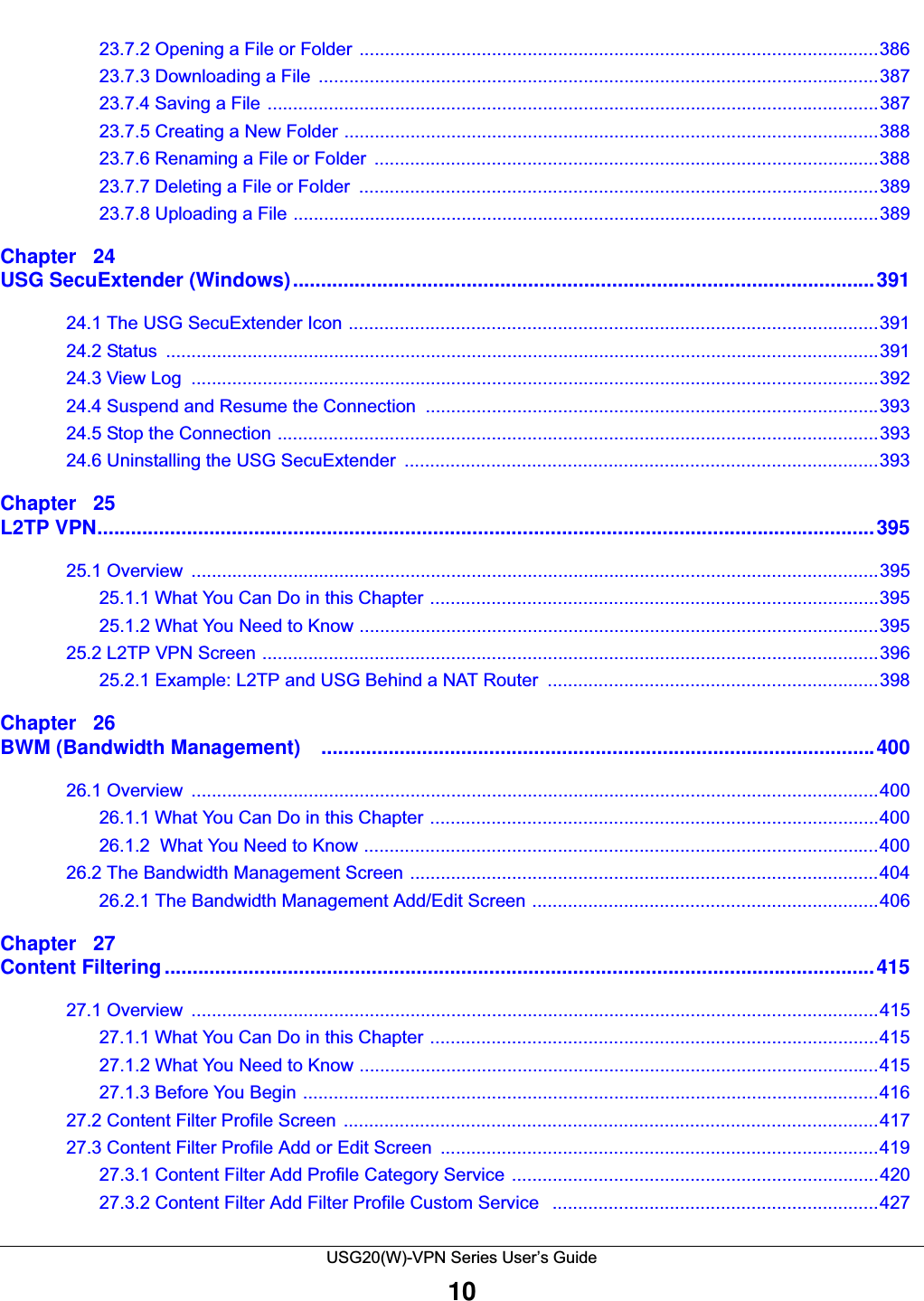
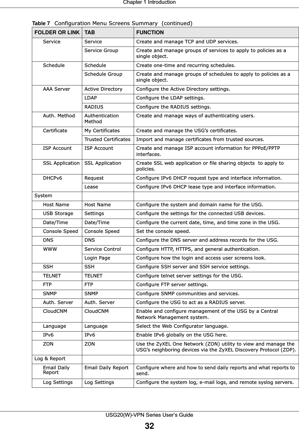
![Chapter 1 IntroductionUSG20(W)-VPN Series User’s Guide35Figure 20 Common Table IconsHere are descriptions for the most common table icons.Working with ListsWhen a list of available entries displays next to a list of selected entries, you can often just double-click an entry to move it from one list to the other. In some lists you can also use the [Shift] or [Ctrl] key to select multiple entries, and then use the arrow button to move them to the other list. Figure 21 Working with Lists Table 9 Common Table IconsLABEL DESCRIPTIONAdd Click this to create a new entry. For features where the entry’s position in the numbered list is important (features where the USG applies the table’s entries in order like the security policy for example), you can select an entry and click Add to create a new entry after the selected entry.Edit Double-click an entry or select it and click Edit to open a screen where you can modify the entry’s settings. In some tables you can just click a table entry and edit it directly in the table. For those types of tables small red triangles display for table entries with changes that you have not yet applied.Remove To remove an entry, select it and click Remove. The USG confirms you want to remove it before doing so.Activate To turn on an entry, select it and click Activate.Inactivate To turn off an entry, select it and click Inactivate.Connect To connect an entry, select it and click Connect. Disconnect To disconnect an entry, select it and click Disconnect. Object ReferencesSelect an entry and click Object References to check which settings use the entry. Move To change an entry’s position in a numbered list, select it and click Move to display a field to type a number for where you want to put that entry and press [ENTER] to move the entry to the number that you typed. For example, if you type 6, the entry you are moving becomes number 6 and the previous entry 6 (if there is one) gets pushed up (or down) one.](https://usermanual.wiki/ZyXEL-Communications/USG20W-VPN.Users-Manual-Part-1/User-Guide-2904713-Page-35.png)
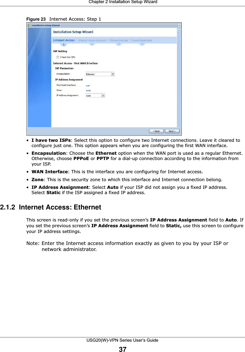
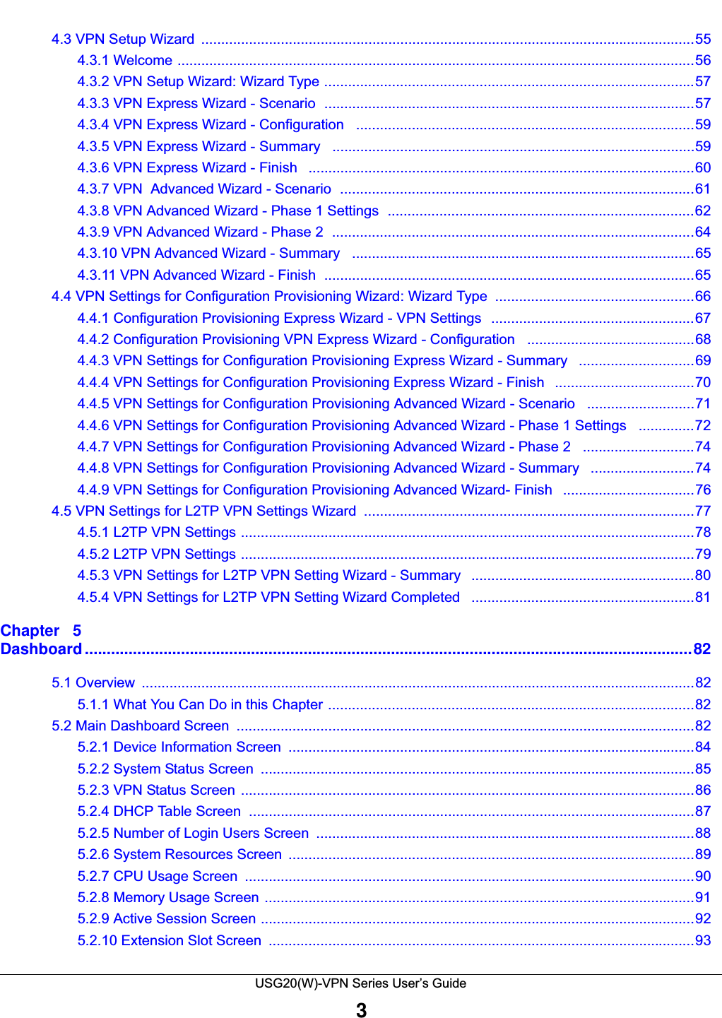
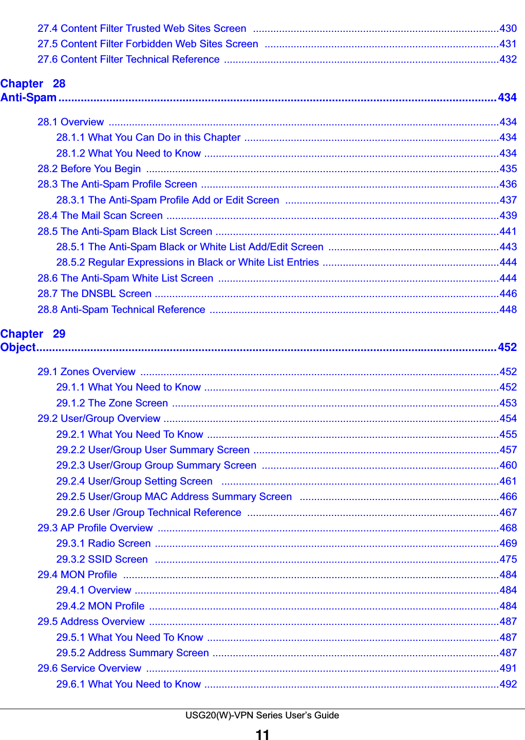
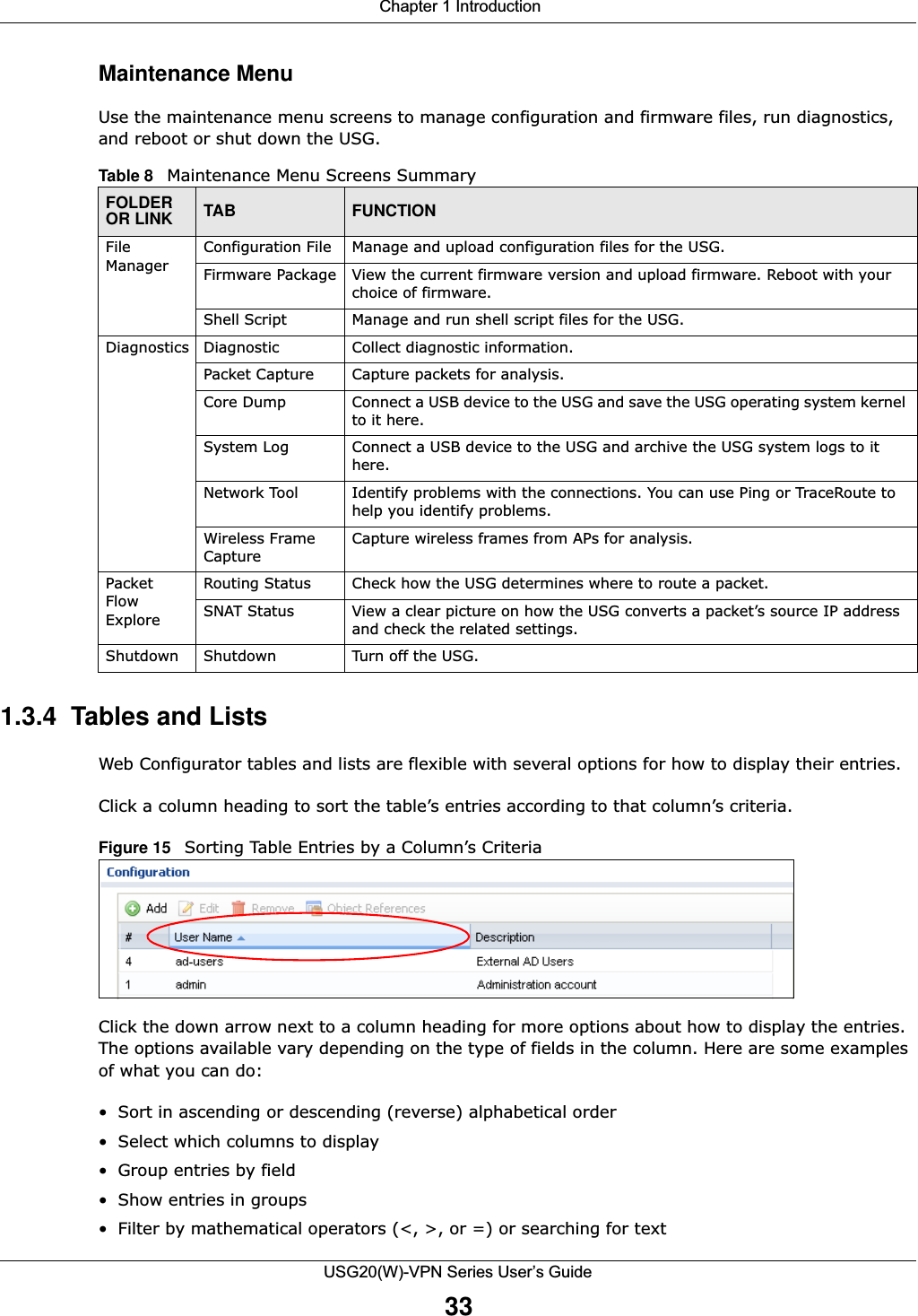
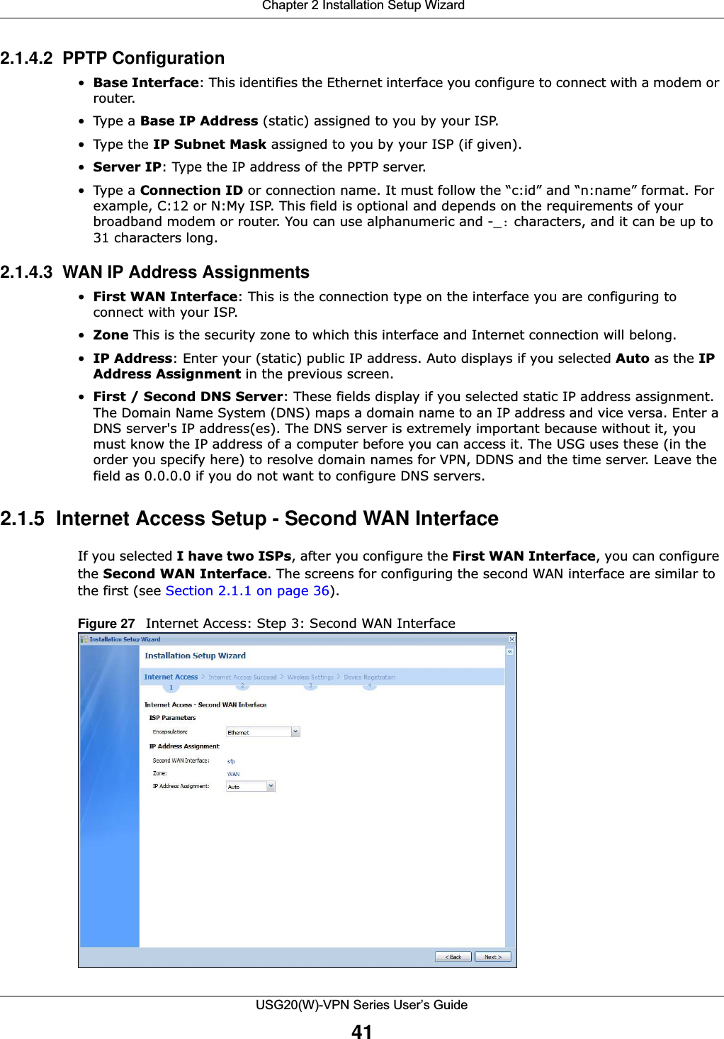
![Chapter 2 Installation Setup WizardUSG20(W)-VPN Series User’s Guide39Figure 25 Internet Access: PPPoE Encapsulation 2.1.3.1 ISP Parameters • Type the PPPoE Service Name from your service provider. PPPoE uses a service name to identify and reach the PPPoE server. You can use alphanumeric and -_@$./ characters, and it can be up to 64 characters long. •Authentication Type - Select an authentication protocol for outgoing connection requests. Options are:•CHAP/PAP - Your USG accepts either CHAP or PAP when requested by the remote node. •CHAP - Your USG accepts CHAP only. •PAP - Your USG accepts PAP only. •MSCHAP - Your USG accepts MSCHAP only.•MSCHAP-V2 - Your USG accepts MSCHAP-V2 only.•Type the User Name given to you by your ISP. You can use alphanumeric and -_@$./ characters, and it can be up to 31 characters long. •Type the Password associated with the user name. Use up to 64 ASCII characters except the [] and ?. This field can be blank.•Select Nailed-Up if you do not want the connection to time out. Otherwise, type the Idle Timeout in seconds that elapses before the router automatically disconnects from the PPPoE server. 2.1.3.2 WAN IP Address Assignments •WAN Interface: This is the name of the interface that will connect with your ISP.•Zone: This is the security zone to which this interface and Internet connection will belong.•IP Address: Enter your (static) public IP address. Auto displays if you selected Auto as the IPAddress Assignment in the previous screen.](https://usermanual.wiki/ZyXEL-Communications/USG20W-VPN.Users-Manual-Part-1/User-Guide-2904713-Page-39.png)
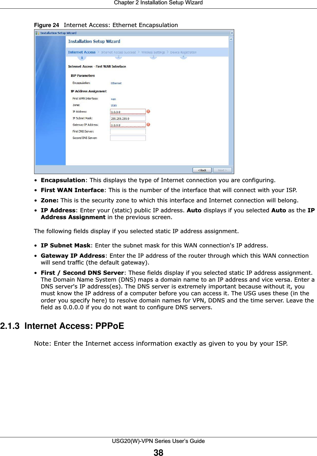
![Chapter 2 Installation Setup WizardUSG20(W)-VPN Series User’s Guide40•First / Second DNS Server: These fields display if you selected static IP address assignment. The Domain Name System (DNS) maps a domain name to an IP address and vice versa. Enter a DNS server's IP address(es). The DNS server is extremely important because without it, you must know the IP address of a computer before you can access it. The USG uses these (in the order you specify here) to resolve domain names for VPN, DDNS and the time server. Leave the field as 0.0.0.0 if you do not want to configure DNS servers. If you do not configure a DNS server, you must know the IP address of a machine in order to access it.2.1.4 Internet Access: PPTP Note: Enter the Internet access information exactly as given to you by your ISP.Figure 26 Internet Access: PPTP Encapsulation 2.1.4.1 ISP Parameters •Authentication Type - Select an authentication protocol for outgoing calls. Options are:•CHAP/PAP - Your USG accepts either CHAP or PAP when requested by the remote node. •CHAP - Your USG accepts CHAP only. •PAP - Your USG accepts PAP only. •MSCHAP - Your USG accepts MSCHAP only.•MSCHAP-V2 - Your USG accepts MSCHAP-V2 only.•Type the User Name given to you by your ISP. You can use alphanumeric and -_@$./ characters, and it can be up to 31 characters long. •Type the Password associated with the user name. Use up to 64 ASCII characters except the [] and ?. This field can be blank. Re-type your password in the next field to confirm it.•Select Nailed-Up if you do not want the connection to time out. Otherwise, type the Idle Timeout in seconds that elapses before the router automatically disconnects from the PPTP server.](https://usermanual.wiki/ZyXEL-Communications/USG20W-VPN.Users-Manual-Part-1/User-Guide-2904713-Page-40.png)
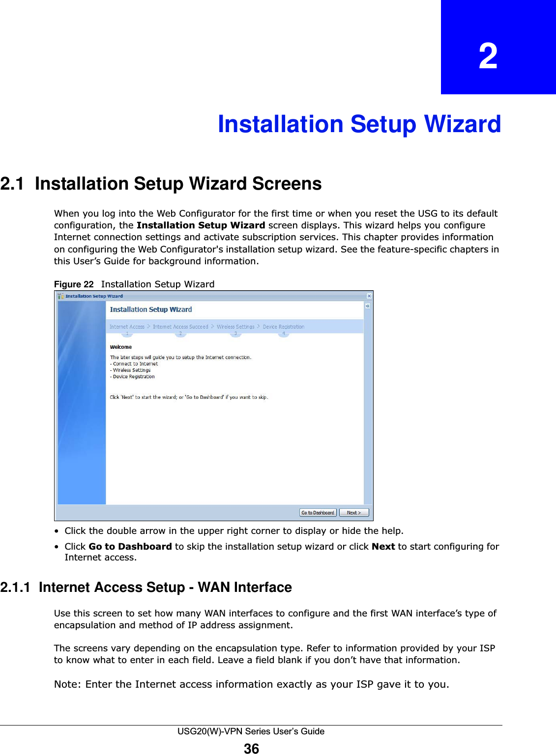
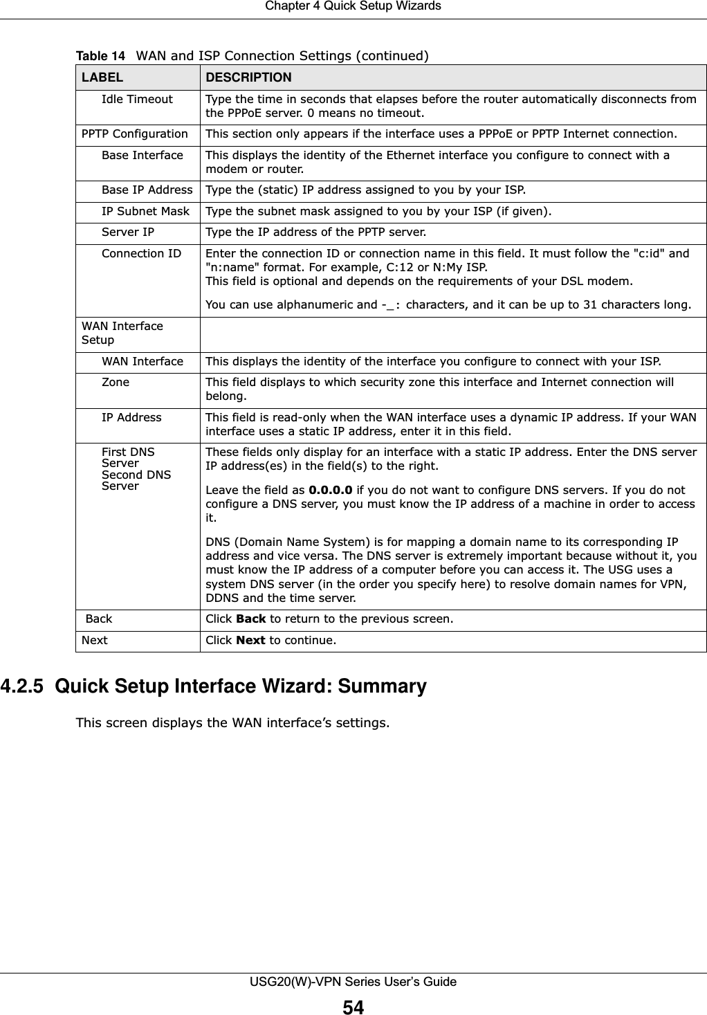
![Chapter 4 Quick Setup WizardsUSG20(W)-VPN Series User’s Guide53Figure 42 WAN and ISP Connection Settings: (PPTP Shown) The following table describes the labels in this screen. Table 14 WAN and ISP Connection SettingsLABEL DESCRIPTIONISP Parameter This section appears if the interface uses a PPPoE or PPTP Internet connection.Encapsulation This displays the type of Internet connection you are configuring.Authentication Type Use the drop-down list box to select an authentication protocol for outgoing calls. Options are:CHAP/PAP - Your USG accepts either CHAP or PAP when requested by this remote node. CHAP - Your USG accepts CHAP only. PAP - Your USG accepts PAP only. MSCHAP - Your USG accepts MSCHAP only.MSCHAP-V2 - Your USG accepts MSCHAP-V2 only.User Name Type the user name given to you by your ISP. You can use alphanumeric and -_@$./ characters, and it can be up to 31 characters long. Password Type the password associated with the user name above. Use up to 64 ASCII characters except the [] and ?. This field can be blank.Retype to Confirm Type your password again for confirmation.Nailed-Up Select Nailed-Up if you do not want the connection to time out.](https://usermanual.wiki/ZyXEL-Communications/USG20W-VPN.Users-Manual-Part-1/User-Guide-2904713-Page-53.png)

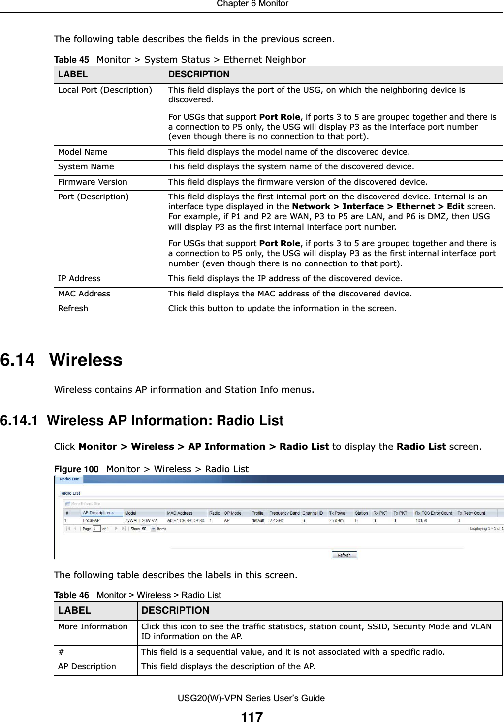
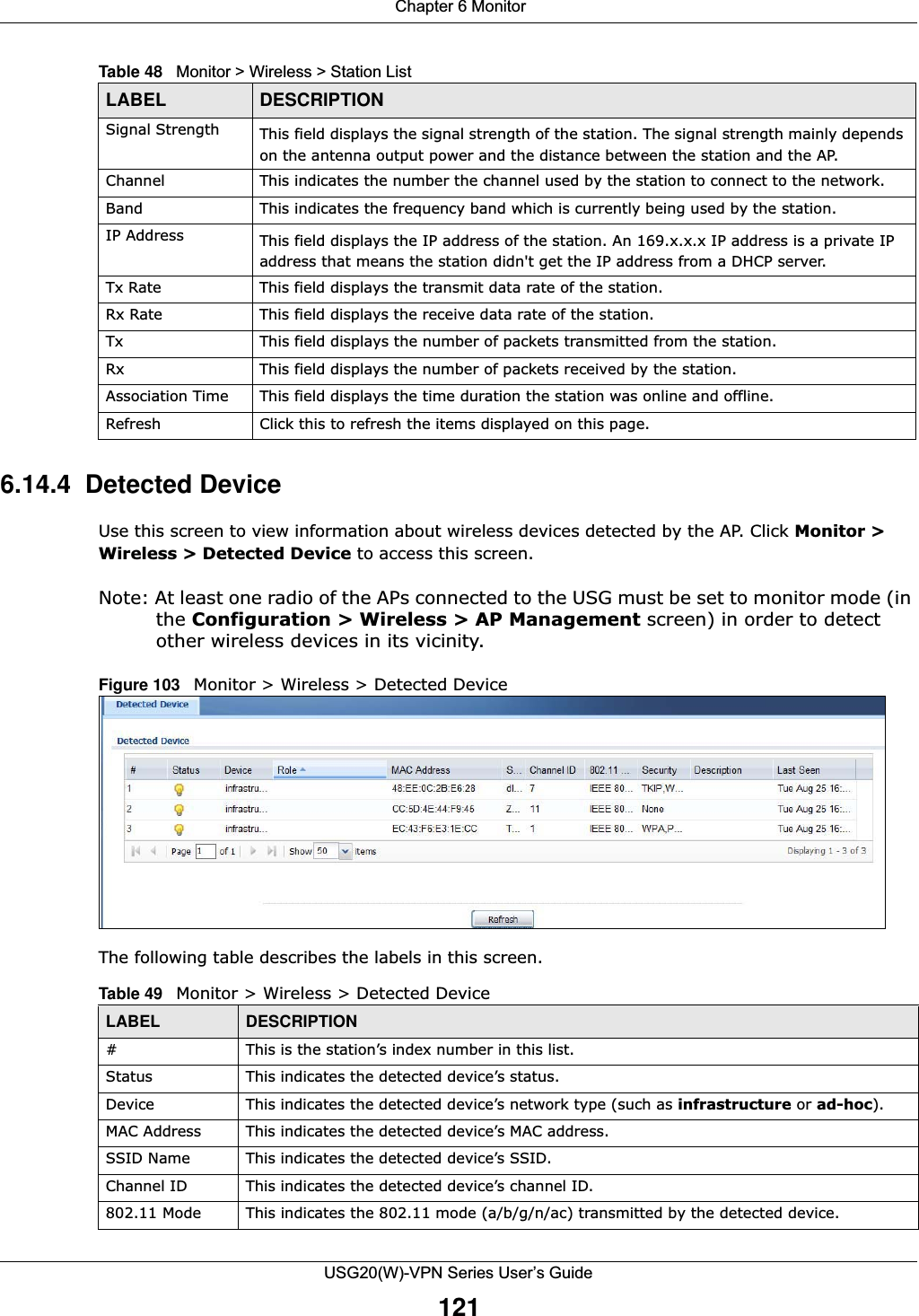
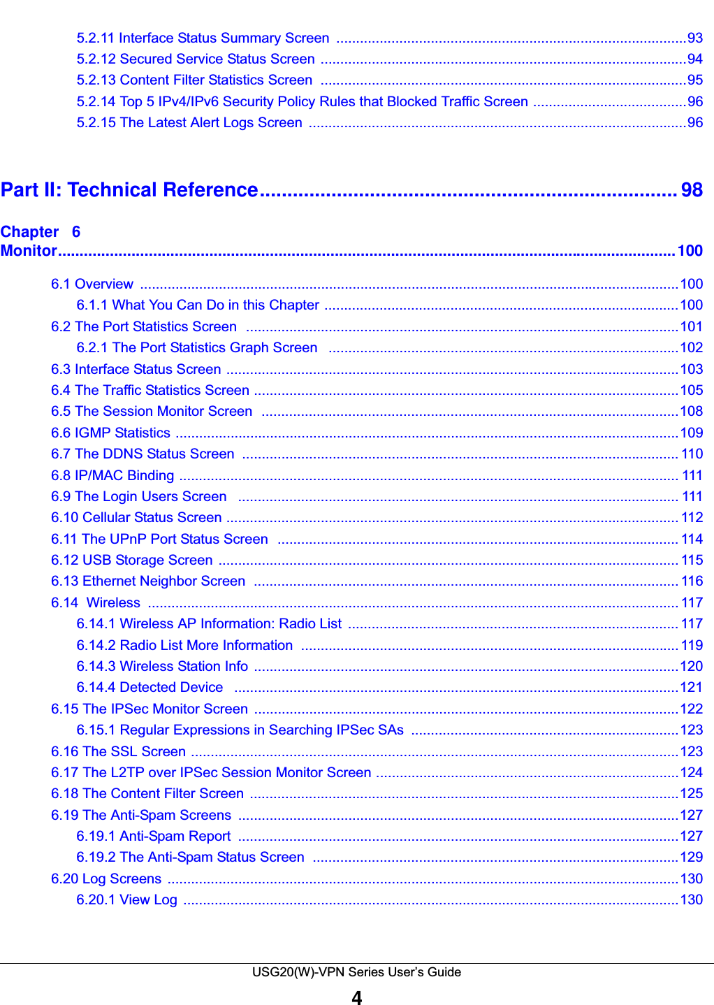
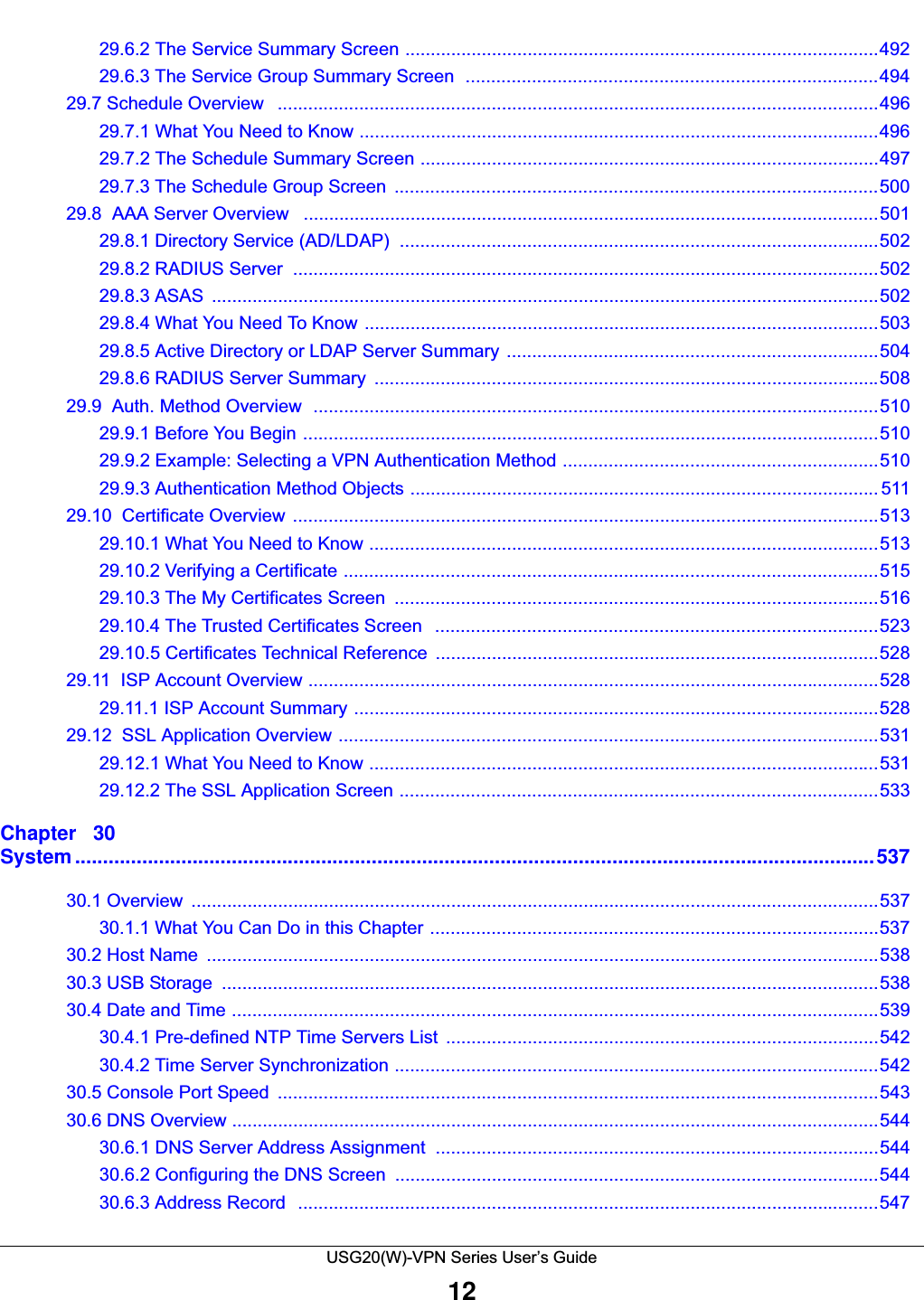
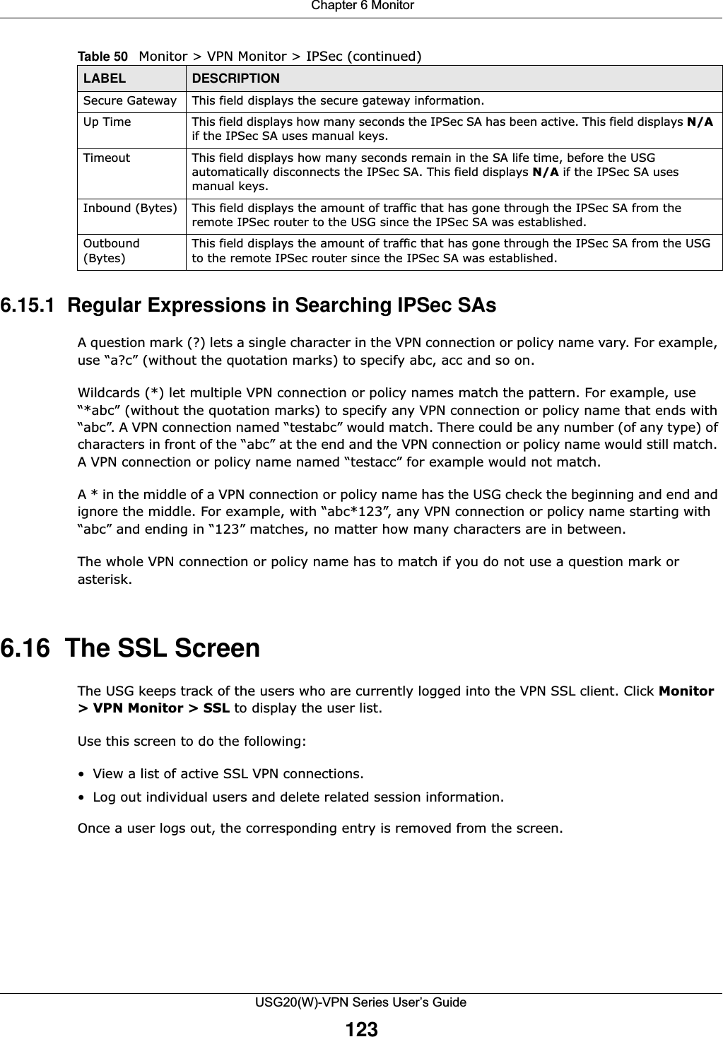
![Chapter 6 MonitorUSG20(W)-VPN Series User’s Guide1226.15 The IPSec Monitor ScreenYou can use the IPSec Monitor screen to display and to manage active IPSec To access this screen, click Monitor > VPN Monitor > IPSec. The following screen appears. SAs. Click a column’s heading cell to sort the table entries by that column’s criteria. Click the heading cell again to reverse the sort order.Figure 104 Monitor > VPN Monitor > IPSecEach field is described in the following table. Security This indicates the encryption method (if any) used by the detected device.Description This displays the detected device’s description. For more on managing friendly and rogue APs, see the Configuration > Wireless > MON Mode screen.Last Seen This indicates the last time the device was detected by the USG.Refresh Click this to refresh the items displayed on this page.Table 49 Monitor > Wireless > Detected Device (continued)LABEL DESCRIPTIONTable 50 Monitor > VPN Monitor > IPSecLABEL DESCRIPTIONName Type the name of a IPSec SA here and click Search to find it (if it is associated). You can use a keyword or regular expression. Use up to 30 alphanumeric and _+-.()!$*^:?|{}[]<>/ characters. See Section 6.15.1 on page 123 for more details. Policy Type the IP address(es) or names of the local and remote policies for an IPSec SA and click Search to find it. You can use a keyword or regular expression. Use up to 30 alphanumeric and _+-.()!$*^:?|{}[]<>/ characters. See Section 6.15.1 on page 123 for more details. Search Click this button to search for an IPSec SA that matches the information you specified above.Disconnect Select an IPSec SA and click this button to disconnect it.# This field is a sequential value, and it is not associated with a specific SA.Name This field displays the name of the IPSec SA.Policy This field displays the content of the local and remote policies for this IPSec SA. The IP addresses, not the address objects, are displayed.IKE Name This field displays the Internet Key Exchange (IKE) name.Cookies This field displays the cookies information that initiates the IKE.My Address This field displays the IP address of local computer.](https://usermanual.wiki/ZyXEL-Communications/USG20W-VPN.Users-Manual-Part-1/User-Guide-2904713-Page-122.png)
![Chapter 6 MonitorUSG20(W)-VPN Series User’s Guide131Figure 110 Monitor > Log > View LogThe following table describes the labels in this screen. Table 56 Monitor > Log > View LogLABEL DESCRIPTIONShow Filter Click this button to show or hide the filter settings.If the filter settings are hidden, the Display, Email Log Now, Refresh, and Clear Log fields are available.If the filter settings are shown, the Display, Priority, Source Address, Destination Address, Service, Keyword, and Search fields are available.Display Select the category of log message(s) you want to view. You can also view All Logs at one time, or you can view the Debug Log.Email Log Now Click this button to send log message(s) to the Active e-mail address(es) specified in the Send Log To field on the Log Settings page.Refresh Click this button to update the information in the screen.Clear Log Click this button to clear the whole log, regardless of what is currently displayed on the screen.# This field is a sequential value, and it is not associated with a specific log message.Time This field displays the time the log message was recorded.Priority This displays when you show the filter. Select the priority of log messages to display. The log displays the log messages with this priority or higher. Choices are: any, emerg, alert, crit, error, warn, notice, and info, from highest priority to lowest priority. This field is read-only if the Category is Debug Log. Category This field displays the log that generated the log message. It is the same value used in the Display and (other) Category fields.Message This field displays the reason the log message was generated. The text “[count=x]”, where x is a number, appears at the end of the Message field if log consolidation is turned on and multiple entries were aggregated to generate into this one.Source This displays when you show the filter. Type the source IP address of the incoming packet that generated the log message. Do not include the port in this filter.Destination This displays when you show the filter. Type the IP address of the destination of the incoming packet when the log message was generated. Do not include the port in this filter.Protocol This displays when you show the filter. Select a service protocol whose log messages you would like to see. Search This displays when you show the filter. Click this button to update the log using the current filter settings.](https://usermanual.wiki/ZyXEL-Communications/USG20W-VPN.Users-Manual-Part-1/User-Guide-2904713-Page-131.png)