ADC Telecommunications DLC0802A Digivance 800 MHz 20 Watts System User Manual 75150
ADC Telecommunications Inc Digivance 800 MHz 20 Watts System 75150
Contents
manual1
Preliminary
ADCP-75-150
Preliminary Issue A
March 2003
1256380 Rev A
Digivance™ 800 MHz 20 Watt System
Installation and Operation Manual
18641-A
FCC ID: F8I-DLC0802A User Manual - Part 1

ADCP-75-150
Preliminary Issue A
March 2003
1256380 Rev A
Digivance™ 800 MHz 20 Watt System
Installation and Operation Manual

ADCP-75-150 • Preliminary Issue A • March 2003 • Preface
Page ii
COPYRIGHT
©2003, ADC Telecommunications, Inc.
All Rights Reserved
Printed in the U.S.A.
REVISION HISTORY
TRADEMARK INFORMATION
ADC and PowerWorx are registered trademarks of ADC Telecommunications, Inc.
Digivance is atrademark of ADC Telecommunications, Inc.
Procomm Plus is aregistered trademark of Quarterdeck Corporation.
DISCLAIMER OF LIABILITY
Contents herein are current as of the date of publication. ADC reserves the right to change the contents without prior notice. In no
event shall ADC be liable for any damages resulting from loss of data, loss of use, or loss of profits and ADC further
disclaims any and all liability for indirect, incidental, special, consequential or other similar damages. This disclaimer of
liability applies to all products, publications and services during and after the warranty period.
This publication may be verified at any time by contacting ADC’s Technical Assistance Center at 1-800-366-3891, extension 73475
(in U.S.A. or Canada) or 952-917-3475 (outside U.S.A. and Canada), or by e-mail to connectivity_tac@adc.com
ISSUE DATE REASON FOR CHANGE
A 03/2003 Original issue.
ADC Telecommunications, Inc.
P.O. Box 1101, Minneapolis, Minnesota 55440-1101
In U.S.A. and Canada: 1-800-366-3891
Outside U.S.A. and Canada: (952) 938-8080
Fax: (952) 917-1717

ADCP-75-150 • Preliminary Issue A • March 2003 • Preface
Page iii
©2003, ADC Telecommunications, Inc.
TABLE OF CONTENTS
Content Page
ABOUT THIS MANUAL . . . . . . . . . . . . . . . . . . . . . . . . . . . . . . . . . . . . . . . . . . . . . . . . . . . . . . . . . . . . . . . . . . . . . . . . vii
RELATED PUBLICATIONS . . . . . . . . . . . . . . . . . . . . . . . . . . . . . . . . . . . . . . . . . . . . . . . . . . . . . . . . . . . . . . . . . . . . . . vii
ADMONISHMENTS . . . . . . . . . . . . . . . . . . . . . . . . . . . . . . . . . . . . . . . . . . . . . . . . . . . . . . . . . . . . . . . . . . . . . . . . . . viii
GENERAL SAFETY PRECAUTIONS . . . . . . . . . . . . . . . . . . . . . . . . . . . . . . . . . . . . . . . . . . . . . . . . . . . . . . . . . . . . . . . .viii
STANDARDS CERTIFICATION . . . . . . . . . . . . . . . . . . . . . . . . . . . . . . . . . . . . . . . . . . . . . . . . . . . . . . . . . . . . . . . . . . . . ix
LIST OF ACRONYMS AND ABBREVIATIONS . . . . . . . . . . . . . . . . . . . . . . . . . . . . . . . . . . . . . . . . . . . . . . . . . . . . . . . . . . . ix
SECTION 1:
OVERVIEW
1 INTRODUCTION. . . . . . . . . . . . . . . . . . . . . . . . . . . . . . . . . . . . . . . . . . . . . . . . . . . . . . . . . . . . . . . . . . . . . . . .1-1
2 800 MHZ 20 WATT SYSTEM OVERVIEW . . . . . . . . . . . . . . . . . . . . . . . . . . . . . . . . . . . . . . . . . . . . . . . . . . . . . . .1-1
2.1 Basic System Components . . . . . . . . . . . . . . . . . . . . . . . . . . . . . . . . . . . . . . . . . . . . . . . . . . . . . . . . . .1-1
2.2 Base Transceiver Station to Host Unit Interface . . . . . . . . . . . . . . . . . . . . . . . . . . . . . . . . . . . . . . . . . . . .1-3
2.3 Handset Interface . . . . . . . . . . . . . . . . . . . . . . . . . . . . . . . . . . . . . . . . . . . . . . . . . . . . . . . . . . . . . . . .1-4
2.4 Local Service Interface. . . . . . . . . . . . . . . . . . . . . . . . . . . . . . . . . . . . . . . . . . . . . . . . . . . . . . . . . . . . .1-4
2.5 Remote NOC Interface . . . . . . . . . . . . . . . . . . . . . . . . . . . . . . . . . . . . . . . . . . . . . . . . . . . . . . . . . . . . .1-5
3 SYSTEM FUNCTIONS AND FEATURES . . . . . . . . . . . . . . . . . . . . . . . . . . . . . . . . . . . . . . . . . . . . . . . . . . . . . . . .1-6
3.1 Fiber Optic Transport . . . . . . . . . . . . . . . . . . . . . . . . . . . . . . . . . . . . . . . . . . . . . . . . . . . . . . . . . . . . . .1-6
3.2 Control and Monitoring Software . . . . . . . . . . . . . . . . . . . . . . . . . . . . . . . . . . . . . . . . . . . . . . . . . . . . . .1-9
3.3 Fault Detection and Alarm Reporting . . . . . . . . . . . . . . . . . . . . . . . . . . . . . . . . . . . . . . . . . . . . . . . . . . .1-9
3.4 Powering . . . . . . . . . . . . . . . . . . . . . . . . . . . . . . . . . . . . . . . . . . . . . . . . . . . . . . . . . . . . . . . . . . . . . .1-9
3.5 Equipment Mounting and Configuration . . . . . . . . . . . . . . . . . . . . . . . . . . . . . . . . . . . . . . . . . . . . . . . . .1-9
SECTION 2:
DESCRIPTION
1 INTRODUCTION. . . . . . . . . . . . . . . . . . . . . . . . . . . . . . . . . . . . . . . . . . . . . . . . . . . . . . . . . . . . . . . . . . . . . . . .2-3
2 HOST UNIT . . . . . . . . . . . . . . . . . . . . . . . . . . . . . . . . . . . . . . . . . . . . . . . . . . . . . . . . . . . . . . . . . . . . . . . . . . .2-3
2.1 Primary Components . . . . . . . . . . . . . . . . . . . . . . . . . . . . . . . . . . . . . . . . . . . . . . . . . . . . . . . . . . . . . .2-3
2.2 Mounting . . . . . . . . . . . . . . . . . . . . . . . . . . . . . . . . . . . . . . . . . . . . . . . . . . . . . . . . . . . . . . . . . . . . . .2-3
2.3 Fault Detection and Alarm Reporting . . . . . . . . . . . . . . . . . . . . . . . . . . . . . . . . . . . . . . . . . . . . . . . . . . .2-4
2.4 RF Signal Connections . . . . . . . . . . . . . . . . . . . . . . . . . . . . . . . . . . . . . . . . . . . . . . . . . . . . . . . . . . . . .2-4
2.5 RF Signal Level Adjustments. . . . . . . . . . . . . . . . . . . . . . . . . . . . . . . . . . . . . . . . . . . . . . . . . . . . . . . . .2-4
2.6 Propagation Delay . . . . . . . . . . . . . . . . . . . . . . . . . . . . . . . . . . . . . . . . . . . . . . . . . . . . . . . . . . . . . . . .2-5
2.7 Optical Connection . . . . . . . . . . . . . . . . . . . . . . . . . . . . . . . . . . . . . . . . . . . . . . . . . . . . . . . . . . . . . . .2-5
2.8 Controller Area Network Interface Connection . . . . . . . . . . . . . . . . . . . . . . . . . . . . . . . . . . . . . . . . . . . . .2-5
2.9 Service Interface Connection. . . . . . . . . . . . . . . . . . . . . . . . . . . . . . . . . . . . . . . . . . . . . . . . . . . . . . . . .2-5
2.10 Powering . . . . . . . . . . . . . . . . . . . . . . . . . . . . . . . . . . . . . . . . . . . . . . . . . . . . . . . . . . . . . . . . . . . . . .2-5
2.11 Cooling . . . . . . . . . . . . . . . . . . . . . . . . . . . . . . . . . . . . . . . . . . . . . . . . . . . . . . . . . . . . . . . . . . . . . . .2-6
2.12 User Interface . . . . . . . . . . . . . . . . . . . . . . . . . . . . . . . . . . . . . . . . . . . . . . . . . . . . . . . . . . . . . . . . . . .2-6
3 REMOTE UNIT OUTDOOR CABINET . . . . . . . . . . . . . . . . . . . . . . . . . . . . . . . . . . . . . . . . . . . . . . . . . . . . . . . . . .2-7
TABLE OF CONTENTS

ADCP-75-150 • Preliminary Issue A • March 2003 • Preface
Page iv
©2003, ADC Telecommunications, Inc.
TABLE OF CONTENTS
Content Page
3.1 Primary Components . . . . . . . . . . . . . . . . . . . . . . . . . . . . . . . . . . . . . . . . . . . . . . . . . . . . . . . . . . . . . . 2-8
3.2 Mounting . . . . . . . . . . . . . . . . . . . . . . . . . . . . . . . . . . . . . . . . . . . . . . . . . . . . . . . . . . . . . . . . . . . . . . 2-9
3.3 STM and LPA Module Installation . . . . . . . . . . . . . . . . . . . . . . . . . . . . . . . . . . . . . . . . . . . . . . . . . . . . . 2-9
3.4 WDM and CWDM Intallation . . . . . . . . . . . . . . . . . . . . . . . . . . . . . . . . . . . . . . . . . . . . . . . . . . . . . . . . . 2-9
3.5 Fiber Optic Cable Entry . . . . . . . . . . . . . . . . . . . . . . . . . . . . . . . . . . . . . . . . . . . . . . . . . . . . . . . . . . . . 2-9
3.6 Antenna Cable Connection . . . . . . . . . . . . . . . . . . . . . . . . . . . . . . . . . . . . . . . . . . . . . . . . . . . . . . . . . 2-10
3.7 AC Power Wiring and Grounding . . . . . . . . . . . . . . . . . . . . . . . . . . . . . . . . . . . . . . . . . . . . . . . . . . . . . 2-10
3.8 Ventilation . . . . . . . . . . . . . . . . . . . . . . . . . . . . . . . . . . . . . . . . . . . . . . . . . . . . . . . . . . . . . . . . . . . . 2-10
3.9 User Interface. . . . . . . . . . . . . . . . . . . . . . . . . . . . . . . . . . . . . . . . . . . . . . . . . . . . . . . . . . . . . . . . . . 2-10
4 REMOTE UNIT INDOOR MOUNTING SHELF . . . . . . . . . . . . . . . . . . . . . . . . . . . . . . . . . . . . . . . . . . . . . . . . . . . . 2-12
4.1 Primary Components . . . . . . . . . . . . . . . . . . . . . . . . . . . . . . . . . . . . . . . . . . . . . . . . . . . . . . . . . . . . . 2-12
4.2 STM and LPA Module Installation . . . . . . . . . . . . . . . . . . . . . . . . . . . . . . . . . . . . . . . . . . . . . . . . . . . . 2-13
4.3 WDM and CWDM Installation . . . . . . . . . . . . . . . . . . . . . . . . . . . . . . . . . . . . . . . . . . . . . . . . . . . . . . . 2-13
4.4 Fiber Optic Cable Installation . . . . . . . . . . . . . . . . . . . . . . . . . . . . . . . . . . . . . . . . . . . . . . . . . . . . . . . 2-13
4.5 Antenna Cable Connections . . . . . . . . . . . . . . . . . . . . . . . . . . . . . . . . . . . . . . . . . . . . . . . . . . . . . . . . 2-14
4.6 AC Power Wiring and Grounding . . . . . . . . . . . . . . . . . . . . . . . . . . . . . . . . . . . . . . . . . . . . . . . . . . . . . 2-14
4.7 User Interface. . . . . . . . . . . . . . . . . . . . . . . . . . . . . . . . . . . . . . . . . . . . . . . . . . . . . . . . . . . . . . . . . . 2-14
5 SPECTRUM TRANSPORT MODULE . . . . . . . . . . . . . . . . . . . . . . . . . . . . . . . . . . . . . . . . . . . . . . . . . . . . . . . . . 2-15
5.1 Primary Components . . . . . . . . . . . . . . . . . . . . . . . . . . . . . . . . . . . . . . . . . . . . . . . . . . . . . . . . . . . . . 2-15
5.2 Mounting . . . . . . . . . . . . . . . . . . . . . . . . . . . . . . . . . . . . . . . . . . . . . . . . . . . . . . . . . . . . . . . . . . . . . 2-16
5.3 Fault Detection and Alarm Reporting . . . . . . . . . . . . . . . . . . . . . . . . . . . . . . . . . . . . . . . . . . . . . . . . . . 2-16
5.4 Antenna Cable Connection . . . . . . . . . . . . . . . . . . . . . . . . . . . . . . . . . . . . . . . . . . . . . . . . . . . . . . . . . 2-16
5.5 RF Signal Level Adjustment . . . . . . . . . . . . . . . . . . . . . . . . . . . . . . . . . . . . . . . . . . . . . . . . . . . . . . . . 2-17
5.6 Optical Connection . . . . . . . . . . . . . . . . . . . . . . . . . . . . . . . . . . . . . . . . . . . . . . . . . . . . . . . . . . . . . . 2-17
5.7 Service Interface Connection . . . . . . . . . . . . . . . . . . . . . . . . . . . . . . . . . . . . . . . . . . . . . . . . . . . . . . . 2-17
5.8 Powering . . . . . . . . . . . . . . . . . . . . . . . . . . . . . . . . . . . . . . . . . . . . . . . . . . . . . . . . . . . . . . . . . . . . . 2-17
5.9 Cooling . . . . . . . . . . . . . . . . . . . . . . . . . . . . . . . . . . . . . . . . . . . . . . . . . . . . . . . . . . . . . . . . . . . . . . 2-17
5.10 User Interface. . . . . . . . . . . . . . . . . . . . . . . . . . . . . . . . . . . . . . . . . . . . . . . . . . . . . . . . . . . . . . . . . . 2-17
6 LINEAR POWER AMPLIFIER . . . . . . . . . . . . . . . . . . . . . . . . . . . . . . . . . . . . . . . . . . . . . . . . . . . . . . . . . . . . . . 2-19
6.1 Primary Components . . . . . . . . . . . . . . . . . . . . . . . . . . . . . . . . . . . . . . . . . . . . . . . . . . . . . . . . . . . . . 2-19
6.2 Mounting . . . . . . . . . . . . . . . . . . . . . . . . . . . . . . . . . . . . . . . . . . . . . . . . . . . . . . . . . . . . . . . . . . . . . 2-20
6.3 Fault Detection and Alarm Reporting . . . . . . . . . . . . . . . . . . . . . . . . . . . . . . . . . . . . . . . . . . . . . . . . . . 2-20
6.4 Powering . . . . . . . . . . . . . . . . . . . . . . . . . . . . . . . . . . . . . . . . . . . . . . . . . . . . . . . . . . . . . . . . . . . . . 2-20
6.5 Cooling . . . . . . . . . . . . . . . . . . . . . . . . . . . . . . . . . . . . . . . . . . . . . . . . . . . . . . . . . . . . . . . . . . . . . . 2-21
6.6 User Interface. . . . . . . . . . . . . . . . . . . . . . . . . . . . . . . . . . . . . . . . . . . . . . . . . . . . . . . . . . . . . . . . . . 2-21
7 INTERFACE PANELS (ACCESSORY) . . . . . . . . . . . . . . . . . . . . . . . . . . . . . . . . . . . . . . . . . . . . . . . . . . . . . . . . . 2-22
8 WAVELENGTH DIVISION MULTIPLEXER (ACCESSORY). . . . . . . . . . . . . . . . . . . . . . . . . . . . . . . . . . . . . . . . . . . . 2-23
9 COARSE WAVELENGTH DIVISION MULTIPLER SYSTEM (ACCESSORY) . . . . . . . . . . . . . . . . . . . . . . . . . . . . . . . . . 2-24
10 DIGIVANCE ELEMENT MANAGEMENT SYSTEM . . . . . . . . . . . . . . . . . . . . . . . . . . . . . . . . . . . . . . . . . . . . . . . . . 2-25
10.1 Primary Components . . . . . . . . . . . . . . . . . . . . . . . . . . . . . . . . . . . . . . . . . . . . . . . . . . . . . . . . . . . . . 2-25
10.2 Service Interface Connection . . . . . . . . . . . . . . . . . . . . . . . . . . . . . . . . . . . . . . . . . . . . . . . . . . . . . . . 2-26
TABLE OF CONTENTS

ADCP-75-150 • Preliminary Issue A • March 2003 • Preface
Page v
©2003, ADC Telecommunications, Inc.
TABLE OF CONTENTS
Content Page
10.3 NOC Interface Connection . . . . . . . . . . . . . . . . . . . . . . . . . . . . . . . . . . . . . . . . . . . . . . . . . . . . . . . . . . 2-26
10.4 DEMS Software User Interface. . . . . . . . . . . . . . . . . . . . . . . . . . . . . . . . . . . . . . . . . . . . . . . . . . . . . . . 2-26
11 SPECIFICATIONS. . . . . . . . . . . . . . . . . . . . . . . . . . . . . . . . . . . . . . . . . . . . . . . . . . . . . . . . . . . . . . . . . . . . . . 2-27
SECTION 3:
HOST UNIT INSTALLATION
1 BEFORE STARTING INSTALLATION . . . . . . . . . . . . . . . . . . . . . . . . . . . . . . . . . . . . . . . . . . . . . . . . . . . . . . . . . .3-1
1.1 Tools and Materials . . . . . . . . . . . . . . . . . . . . . . . . . . . . . . . . . . . . . . . . . . . . . . . . . . . . . . . . . . . . . . .3-1
1.2 Unpacking and Inspection. . . . . . . . . . . . . . . . . . . . . . . . . . . . . . . . . . . . . . . . . . . . . . . . . . . . . . . . . . .3-2
2 OUTDOOR CABINET OSP FIBER CABLE INSTALLATION GUIDELINES . . . . . . . . . . . . . . . . . . . . . . . . . . . . . . . . . . . .3-2
3 WDM MOUNTING PROCEDURE (OPTIONAL ACCESSORY) . . . . . . . . . . . . . . . . . . . . . . . . . . . . . . . . . . . . . . . . . . .3-4
4 HU MOUNTING PROCEDURE . . . . . . . . . . . . . . . . . . . . . . . . . . . . . . . . . . . . . . . . . . . . . . . . . . . . . . . . . . . . . . .3-6
5 CHASSIS GROUND CONNECTION . . . . . . . . . . . . . . . . . . . . . . . . . . . . . . . . . . . . . . . . . . . . . . . . . . . . . . . . . . . .3-8
6 COAXIAL CABLE CONNECTIONS. . . . . . . . . . . . . . . . . . . . . . . . . . . . . . . . . . . . . . . . . . . . . . . . . . . . . . . . . . . . .3-8
7 OPTICAL CONNECTIONS. . . . . . . . . . . . . . . . . . . . . . . . . . . . . . . . . . . . . . . . . . . . . . . . . . . . . . . . . . . . . . . . . 3-10
7.1 Optical Connections Without WDM. . . . . . . . . . . . . . . . . . . . . . . . . . . . . . . . . . . . . . . . . . . . . . . . . . . . 3-10
7.2 Optical Connections With WDM . . . . . . . . . . . . . . . . . . . . . . . . . . . . . . . . . . . . . . . . . . . . . . . . . . . . . . 3-11
8 CONTROLLER AREA NETWORK CONNECTIONS . . . . . . . . . . . . . . . . . . . . . . . . . . . . . . . . . . . . . . . . . . . . . . . . . 3-13
9 SERVICE INTERFACE CONNECTION . . . . . . . . . . . . . . . . . . . . . . . . . . . . . . . . . . . . . . . . . . . . . . . . . . . . . . . . . 3-14
10 EXTERNAL ALARM SYSTEM CONNECTIONS . . . . . . . . . . . . . . . . . . . . . . . . . . . . . . . . . . . . . . . . . . . . . . . . . . . 3-15
11 DC POWER CONNECTIONS . . . . . . . . . . . . . . . . . . . . . . . . . . . . . . . . . . . . . . . . . . . . . . . . . . . . . . . . . . . . . . . 3-16
SECTION 4:
OPERATION
1 BEFORE STARTING OPERATION . . . . . . . . . . . . . . . . . . . . . . . . . . . . . . . . . . . . . . . . . . . . . . . . . . . . . . . . . . . .4-1
1.1 Tools and Materials . . . . . . . . . . . . . . . . . . . . . . . . . . . . . . . . . . . . . . . . . . . . . . . . . . . . . . . . . . . . . . .4-1
1.2 Readiness Check . . . . . . . . . . . . . . . . . . . . . . . . . . . . . . . . . . . . . . . . . . . . . . . . . . . . . . . . . . . . . . . . .4-2
2 TURN-UP SYSTEM AND VERIFY OPERATION . . . . . . . . . . . . . . . . . . . . . . . . . . . . . . . . . . . . . . . . . . . . . . . . . . . .4-2
2.1 Turn-Up Procedure. . . . . . . . . . . . . . . . . . . . . . . . . . . . . . . . . . . . . . . . . . . . . . . . . . . . . . . . . . . . . . . .4-3
2.2 Verify/Download HU and RU System Software . . . . . . . . . . . . . . . . . . . . . . . . . . . . . . . . . . . . . . . . . . . . .4-6
2.3 Determine Forward Path Input Signal Level . . . . . . . . . . . . . . . . . . . . . . . . . . . . . . . . . . . . . . . . . . . . . .4-7
2.4 Enter Site Name and Site Number . . . . . . . . . . . . . . . . . . . . . . . . . . . . . . . . . . . . . . . . . . . . . . . . . . . . 4-10
2.5 Enter Host Forward Attenuation . . . . . . . . . . . . . . . . . . . . . . . . . . . . . . . . . . . . . . . . . . . . . . . . . . . . . . 4-11
2.6 Determine Output Signal Level at STM Antenna Port . . . . . . . . . . . . . . . . . . . . . . . . . . . . . . . . . . . . . . . 4-12
2.7 Enter Remote Forward Attenuation. . . . . . . . . . . . . . . . . . . . . . . . . . . . . . . . . . . . . . . . . . . . . . . . . . . . 4-13
2.8 Enter Host Reverse Attenuation . . . . . . . . . . . . . . . . . . . . . . . . . . . . . . . . . . . . . . . . . . . . . . . . . . . . . . 4-15
2.9 Enter Host Forward and Reverse Delay . . . . . . . . . . . . . . . . . . . . . . . . . . . . . . . . . . . . . . . . . . . . . . . . . 4-17

ADCP-75-150 • Preliminary Issue A • March 2003 • Preface
Page vi
©2003, ADC Telecommunications, Inc.
TABLE OF CONTENTS
Content Page
SECTION 5:
MAINTENANCE
1 SYSTEM MAINTENANCE OVERVIEW . . . . . . . . . . . . . . . . . . . . . . . . . . . . . . . . . . . . . . . . . . . . . . . . . . . . . . . . . 5-1
1.1 Tools and Materials. . . . . . . . . . . . . . . . . . . . . . . . . . . . . . . . . . . . . . . . . . . . . . . . . . . . . . . . . . . . . . . 5-1
2 FAULT DETECTION AND ALARM REPORTING . . . . . . . . . . . . . . . . . . . . . . . . . . . . . . . . . . . . . . . . . . . . . . . . . . . 5-2
3 FAULT ISOLATION AND TROUBLESHOOTING . . . . . . . . . . . . . . . . . . . . . . . . . . . . . . . . . . . . . . . . . . . . . . . . . . . 5-5
4 TEST PROCEDURES . . . . . . . . . . . . . . . . . . . . . . . . . . . . . . . . . . . . . . . . . . . . . . . . . . . . . . . . . . . . . . . . . . . 5-10
4.1 Optical Power Test . . . . . . . . . . . . . . . . . . . . . . . . . . . . . . . . . . . . . . . . . . . . . . . . . . . . . . . . . . . . . . 5-10
4.2 Optical Loopback Test . . . . . . . . . . . . . . . . . . . . . . . . . . . . . . . . . . . . . . . . . . . . . . . . . . . . . . . . . . . . 5-12
5 MAINTENANCE PROCEDURES. . . . . . . . . . . . . . . . . . . . . . . . . . . . . . . . . . . . . . . . . . . . . . . . . . . . . . . . . . . . . 5-13
5.1 Scheduled Maintenance. . . . . . . . . . . . . . . . . . . . . . . . . . . . . . . . . . . . . . . . . . . . . . . . . . . . . . . . . . . 5-13
5.2 Remote Unit Outdoor Cabinet Filters Cleaning Procedure . . . . . . . . . . . . . . . . . . . . . . . . . . . . . . . . . . . . 5-14
5.3 Host Unit Fan Replacement Procedure . . . . . . . . . . . . . . . . . . . . . . . . . . . . . . . . . . . . . . . . . . . . . . . . . 5-15
5.4 Spectrum Transport Module Fan Replacement Procedure . . . . . . . . . . . . . . . . . . . . . . . . . . . . . . . . . . . . 5-16
5.5 Linear Power Amplifier Fan Replacement Procedure . . . . . . . . . . . . . . . . . . . . . . . . . . . . . . . . . . . . . . . 5-19
SECTION 6:
GENERAL INFORMATION
1 WARRANTY/SOFTWARE . . . . . . . . . . . . . . . . . . . . . . . . . . . . . . . . . . . . . . . . . . . . . . . . . . . . . . . . . . . . . . . . . 6-1
2 SOFTWARE SERVICE AGREEMENT . . . . . . . . . . . . . . . . . . . . . . . . . . . . . . . . . . . . . . . . . . . . . . . . . . . . . . . . . . 6-1
3 REPAIR/EXCHANGE POLICY . . . . . . . . . . . . . . . . . . . . . . . . . . . . . . . . . . . . . . . . . . . . . . . . . . . . . . . . . . . . . . . 6-1
4 REPAIR CHARGES. . . . . . . . . . . . . . . . . . . . . . . . . . . . . . . . . . . . . . . . . . . . . . . . . . . . . . . . . . . . . . . . . . . . . . 6-2
5 REPLACEMENT/SPARE PRODUCTS . . . . . . . . . . . . . . . . . . . . . . . . . . . . . . . . . . . . . . . . . . . . . . . . . . . . . . . . . . 6-2
6 RETURNED MATERIAL. . . . . . . . . . . . . . . . . . . . . . . . . . . . . . . . . . . . . . . . . . . . . . . . . . . . . . . . . . . . . . . . . . . 6-2
7 CUSTOMER INFORMATION AND ASSISTANCE. . . . . . . . . . . . . . . . . . . . . . . . . . . . . . . . . . . . . . . . . . . . . . . . . . . 6-3

ADCP-75-150 • Preliminary Issue A • March 2003 • Preface
Page vii
©2003, ADC Telecommunications, Inc.
ABOUT THIS MANUAL
This installation and operation manual provides the following information:
•Anoverview of the Digivance 800 MHz 20 Watt System.
•Adescription of the basic system components including the Host Unit (HU), Spectrum
Transport Module (STM), Linear Power Amplifier (LPA), Remote Unit (RU), and
Digivance Element Management System (DEMS).
• Installation procedures for the HU.
• Procedures for tuning-up the system and verifying that the system is functioning properly.
• Procedures for maintaining the system including troubleshooting problems and replacing
faulty components.
• Product warranty, repair, return, and replacement information.
The procedures for installing the remote unit and for installing and using the DEMS software
are provided in other publications which are referenced in the Related Publications section and
at appropriate points within this manual.
RELATED PUBLICATIONS
Listed below are all the related manuals, their content, and their publication numbers. Copies of
these publications can be ordered by contacting the Technical Assistance Center at
1-800-366-3891,extension 73475 (in U.S.A. or Canada) or 952-917-3475 (outside U.S.A. and
Canada).
Digivance 20 Watt Indoor Remote Unit Installation Instructions 75-149
Provides instructions for installing the STM, LPA, and accessories in the indoor
remote unit mounting shelf and for installing and connecting the fiber optic,
coaxial, and AC power cables.
Digivance 20 Watt Outdoor Remote Unit Installation Instructions 75-148
Provides instructions for installing the STM, LPA, and accessories in the
outdoor remote unit cabinet and for installing and connecting the fiber optic,
coaxial, and AC power cables.
Digivance 20 Watt Remote Unit Cabinet Mounting Instructions 75-147
Provides instructions for locating and mounting the remote unit cabinet.
Digivance Element Management System Version 2.0 User Manual 75-125
Provides instructions for installing the Digivance Element Management System
software and for using both the Graphical User Interface (GUI) and the
Network Operations Center (NOC) versions of the software.
Title/Description ADCP Number

ADCP-75-150 • Preliminary Issue A • March 2003 • Preface
Page viii
©2003, ADC Telecommunications, Inc.
Digivance RF Transport Solution 800 and 1900 MHz Interface
Panels User Manual 75-147
Describes the 800 and 1900 MHz Conditioning Panel and Duplexing Panel and
provides procedures for configuration and installation.
Digivance System Coarse Wavelength Division Multiplexer User Manual 75-142
Describes the Coarse Wavelength Division Multiplexer and provides
procedures for configuration and installation.
ADMONISHMENTS
Important safety admonishments are used throughout this manual to warn of possible hazards to
persons or equipment. An admonishment identifies apossible hazard and then explains what
may happen if the hazard is not avoided. The admonishments —in the form of Dangers,
Warnings, and Cautions —must be followed at all times. These warnings are flagged by use of
the triangular alert icon (seen below), and are listed in descending order of severity of injury or
damage and likelihood of occurrence.
GENERAL SAFETY PRECAUTIONS
Danger: Danger is used to indicate the presence of ahazard that will cause severe personal
injury, death, or substantial property damage if the hazard is not avoided.
Warning: Warning is used to indicate the presence of ahazard that can cause severe personal
injury, death, or substantial property damage if the hazard is not avoided.
Caution: Caution is used to indicate the presence of ahazard that will or can cause minor
personal injury or property damage if the hazard is not avoided.
Danger: This equipment uses aClass 1Laser according to FDA/CDRH rules. Laser radiation
can seriously damage the retina of the eye. Do not look into the ends of any optical fiber. Do not
look directly into the optical transceiver of any digital unit or exposure to laser radiation may
result. An optical power meter should be used to verify active fibers. Aprotective cap or hood
MUST be immediately placed over any radiating transceiver or optical fiber connector to avoid
the potential of dangerous amounts of radiation exposure. This practice also prevents dirt
particles from entering the adapter or connector.
Danger: Do not look into the ends of any optical fiber. Exposure to laser radiation may result.
Do not assume laser power is turned-off or the fiber is disconnected at the other end.
Danger: Wet conditions increase the potential for receiving an electrical shock when installing
or using electrically-powered equipment. To prevent electrical shock, never install or use
electrical equipment in awet location or during alightning storm.

ADCP-75-150 • Preliminary Issue A • March 2003 • Preface
Page ix
©2003, ADC Telecommunications, Inc.
STANDARDS CERTIFICATION
FCC:This equipment complies with the applicable sections of Title 47 CFR Part 22.
UL/CUL:This equipment complies with UL and CUL 50 Standard for Enclosures for
Electrical Equipment. This equipment provides the degree of protection specified by IP43 as
defined in IEC Publication 529.
FDA/CDRH:This equipment uses aClass 1LASER according to FDA/CDRH Rules. This
product conforms to all applicable standards of 21 CFR Part 1040.
IC:This equipment complies with the applicable sections of RSS-131. The term “IC:” before the
radio certification number only signifies that Industry Canada Technical Specifications were met.
LIST OF ACRONYMS AND ABBREVIATIONS
The acronyms and abbreviations used in this manual are detailed in the following list:
AC Alternating Current
ASCII American Standard Code for Information Interchange
Att Attenuation
AWG American Wire Gauge
BER Bit Error Rate
BTS Base Transceiver Station
CCentigrade
CAN Controller Area Network
CDRH Center for Devices and Radiological Health
CD-ROM Compact Disk Read Only Memory
COM Common
Config Configuration
CUL Canadian Underwriters Laboratories
DC Direct Current
DCE Data Communications Equipment
DEMS Digivance Element Management System
DTE Data Terminal Equipment
EIA Electronic Industries Association
Warning: The HU is powered by 48 VDC power which is supplied over customer-provided
wiring. To prevent electrical shock when installing or modifying the HU power wiring,
disconnect the wiring at the power source before working with uninsulated wires or terminals.
Caution: Always allow sufficient fiber length to permit routing of patch cords and pigtails
without severe bends. Fiber optic patch cords or pigtails may be permanently damaged if bent
or curved to aradius of less than 2inches (50 mm).

ADCP-75-150 • Preliminary Issue A • March 2003 • Preface
Page x
©2003, ADC Telecommunications, Inc.
ESD Electrostatic Discharge
FFahrenheit
FCC Federal Communications Commission
FDA Food and Drug Administration
FSO Free Space Optics
Fwd Forward
GUI Graphical User Interface
HU Host Unit
IC Industry Canada
LED Light Emitting Diode
LPA Linear Power Amplifier
MHz Mega Hertz
MPE Maximum Permissible Exposure
MTBF Mean Time Between Failure
NC Normally Closed
NEM Network Element Manager
NO Normally Open
NOC Network Operations Center
NPT National Pipe Tapered
OSP Outside Plant
PA Power Amplifier
PC Personal Computer
PCS Personal Communications System
Prg Program
Pwr Power
Rev Reverse
RF Radio Frequency
RMA Return Material Authorization
RU Remote Unit
RX Receive or Receiver
STM Spectrum Transport Module
TX Transmit or Transmitter
UL Underwriters Laboratories
VAC Volts Alternating Current
VDC Vol ts Direct Current
VSWR Vo ltage Standing Wave Ratio
WECO Western Electric Company
WDM Wave Division Multiplexer

ADCP-75-150 • Preliminary Issue A • March 2003 • Section 1: Overview
Page 1-1
©2003, ADC Telecommunications, Inc.
SECTION 1: OVERVIEW
1 INTRODUCTION. . . . . . . . . . . . . . . . . . . . . . . . . . . . . . . . . . . . . . . . . . . . . . . . . . . . . . . . . . . . . . . . . . . . . . . .1-1
2 800 MHZ 20 WATT SYSTEM OVERVIEW . . . . . . . . . . . . . . . . . . . . . . . . . . . . . . . . . . . . . . . . . . . . . . . . . . . . . . .1-1
2.1 Basic System Components . . . . . . . . . . . . . . . . . . . . . . . . . . . . . . . . . . . . . . . . . . . . . . . . . . . . . . . . . .1-1
2.2 Base Transceiver Station to Host Unit Interface . . . . . . . . . . . . . . . . . . . . . . . . . . . . . . . . . . . . . . . . . . . .1-3
2.3 Handset Interface . . . . . . . . . . . . . . . . . . . . . . . . . . . . . . . . . . . . . . . . . . . . . . . . . . . . . . . . . . . . . . . .1-4
2.4 Local Service Interface. . . . . . . . . . . . . . . . . . . . . . . . . . . . . . . . . . . . . . . . . . . . . . . . . . . . . . . . . . . . .1-4
2.5 Remote NOC Interface . . . . . . . . . . . . . . . . . . . . . . . . . . . . . . . . . . . . . . . . . . . . . . . . . . . . . . . . . . . . .1-5
3 SYSTEM FUNCTIONS AND FEATURES . . . . . . . . . . . . . . . . . . . . . . . . . . . . . . . . . . . . . . . . . . . . . . . . . . . . . . . .1-6
3.1 Fiber Optic Transport . . . . . . . . . . . . . . . . . . . . . . . . . . . . . . . . . . . . . . . . . . . . . . . . . . . . . . . . . . . . . .1-6
3.2 Control and Monitoring Software . . . . . . . . . . . . . . . . . . . . . . . . . . . . . . . . . . . . . . . . . . . . . . . . . . . . . .1-9
3.3 Fault Detection and Alarm Reporting . . . . . . . . . . . . . . . . . . . . . . . . . . . . . . . . . . . . . . . . . . . . . . . . . . .1-9
3.4 Powering . . . . . . . . . . . . . . . . . . . . . . . . . . . . . . . . . . . . . . . . . . . . . . . . . . . . . . . . . . . . . . . . . . . . . .1-9
3.5 Equipment Mounting and Configuration . . . . . . . . . . . . . . . . . . . . . . . . . . . . . . . . . . . . . . . . . . . . . . . . .1-9
_________________________________________________________________________________________________________
1 INTRODUCTION
This section provides basic description, application, and configuration information about the
Digivance 800 MHz 20 Watt System. Throughout this publication, all items referenced as
“accessory items” are not furnished with the basic product and must be purchased separately.
2 800 MHZ 20 WATT SYSTEM OVERVIEW
The Digivance 800 MHz 20 Watt System is an RF signal transport system that provides long-
range RF coverage in areas where it is impractical to place aBase Transceiver Station (BTS) at
the antenna site. High real estate costs and community restrictions on tower and equipment
locations often make it difficult to install the BTS at the same location as the antenna. The
Digivance system is designed to overcome equipment placement problems by allowing base
stations to be hubbed at acentral location while placing remote antennas at optimum locations
with minimal real estate requirements. With the Digivance system, RF signals can be
transported to one or more remote locations to expand coverage into areas not receiving service
or to extend coverage into difficult to reach areas such as canyons, tunnels, or underground
roadways.
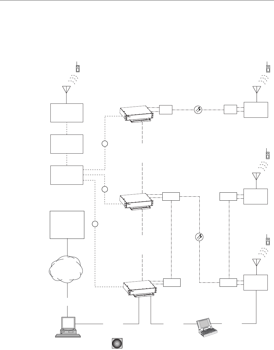
2.1 Basic System Components
The basic components of aDigivance 20 Watt System and their functions are shown in
Figure 1-1. A 20 Watt system consists of the Host Unit (HU) and the Remote Unit (RU). Both
an indoor and an outdoor remote unit are available. Control and monitoring functions are
provided by the Digivance Element Management System (DEMS), aPC-based software
program. In addition, various accessory items are available separately including apassive
Wavelength Division Multiplexer (WDM), an active Coarse Wavelength Division Multiplexer
(CWDM) system, conditioning and duplexing panels (for interfacing the HU with the BTS),
ADCP-75-150 • Preliminary Issue A • March 2003 • Section 1: Overview
Page 1-2
©2003, ADC Telecommunications, Inc.
network cables (for connecting multiple HU’s together), and aDEMS cable (for connecting the
DEMS computer to the HU).
Figure 1-1. 20 Watt System Overview Diagram
BASE
TRANSCEIVER
STATION
DIGIVANCE ELEMENT
MANAGEMENT SYSTEM (DEMS)
HOST UNIT
HOST UNIT
HOST UNIT
NETWORK
OPERATIONS
CENTER
(REMOTE
INTERFACE)
LAPTOP WITH DEMS
(LOCAL INTERFACE)
DATA
NETWORK
CONTROLLER
AREA
NETWORK
RS-232 ASCII
RS-232
18513-A
CD-ROM WITH DEMS
SOFTWARE
DUPLEXING
PANEL
(IF REQUIRED)
CONDITIONING
PANEL
RF
RF
RF
CONTROLLER
AREA
NETWORK
CWDM
WDM REMOTE
UNIT
REMOTE
UNIT
WDM
REMOTE
UNIT
CWDM
CWDM
CWDM
RS-232
RS-232
BASE STATION
ANTENNA
ADCP-75-150 • Preliminary Issue A • March 2003 • Section 1: Overview
Page 1-3
©2003, ADC Telecommunications, Inc.
2.2 Base Transceiver Station to Host Unit Interface
The HU interfaces with the BTS which provides the RF channel inputs and outputs for a
designated sector. The BTS/HU interface may require installation of the Digivance Interface
Panels which are accessory products for the Digivance system. The Interface Panels are used
when multiple BTS’s and multiple Host Units require connection or when RF attenuation is
needed between the BTS and Host Unit.
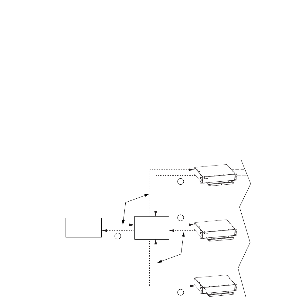
Two types of Interface Panels are available: the Conditioning Panel and the Duplexing Panel. The
Conditioning Panel provides attenuation of the forward path signal to the level required for input
to the Host Unit. The Conditioning Panel also provides forward and reverse path combining and
splitting (as needed) to enable multi-BTS to single Host Unit, multi-BTS to multi-Host Unit, or
single BTS to multi-Host Unit configurations. Atypical single BTS to multi-Host Unit
configuration is shown in Figure 1-2.
Figure 1-2. BTS/HU Interface with Conditioning Panel
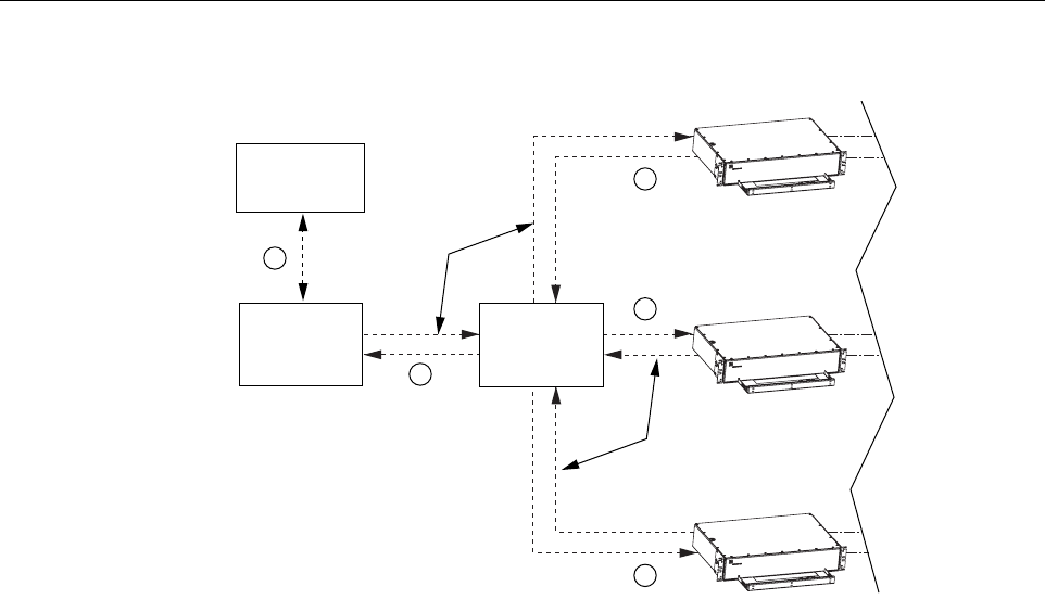
The Duplexing Panel is used in conjunction with the Conditioning Panel when the BTS
provides aduplexed forward and reverse path RF connection as shown in Figure 1-3.The
Duplexing Panel separates the duplexed forward and reverse path signals. This allows the BTS
to be connected to the Host Unit which has separate forward and reverse path RF ports.
18514-A
RF
RF
RF
RF
BASE
TRANSCEIVER
STATION
COAXIAL
CABLES
COAXIAL
CABLES
HOST UNIT
HOST UNIT
HOST UNIT
CONDITIONING
PANEL
ADCP-75-150 • Preliminary Issue A • March 2003 • Section 1: Overview
Page 1-4
©2003, ADC Telecommunications, Inc.
Figure 1-3. BTS/HU Interface With Conditioning Panel and Duplexing Panel
2.3 Handset Interface
The RU interfaces with the handsets (cell phones) through an antenna. In the reverse path, the
RU receives RF signals from each handset. The RU digitizes the RF signals and then converts
them to digital optical signals for transport to the HU over the fiber optic link. In the forward
path, the RU receives digital optical signals from the HU. The RU converts the optical signals to
RF signals for transmission to the handsets. The RU is connected to an antenna (not provided)
which transmits and receives the handset RF signals.
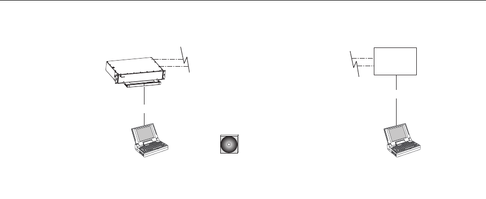
2.4 Local Service Interface
Local communications with an individual Digivance system is supported through alocal service
interface capability as shown in Figure 4. The primary component of the local interface is aPC-
type laptop computer loaded with the Digivance Element Management System (DEMS)
software. DEMS provides the various control and monitoring functions required for local
management of each Digivance system. The DEMS computer can be directly connected to
either the HU or RU through the computer’s RS-232 port. Operation is effected through the
DEMS Graphical User Interface (GUI). The GUI consists of aseries of screens from which the
user selects the desired option or function. An RS-232 service port is provided on both the HU
and the RU for connecting the DEMS computer.
18515-A
RF
RF
RF
RF
RF
BASE
TRANSCEIVER
STATION
COAXIAL
CABLES
COAXIAL
CABLES
HOST UNIT
HOST UNIT
HOST UNIT
CONDITIONING
PANEL
DUPLEXING
PANEL
ADCP-75-150 • Preliminary Issue A • March 2003 • Section 1: Overview
Page 1-5
©2003, ADC Telecommunications, Inc.
Figure 1-4. Local Service Interface
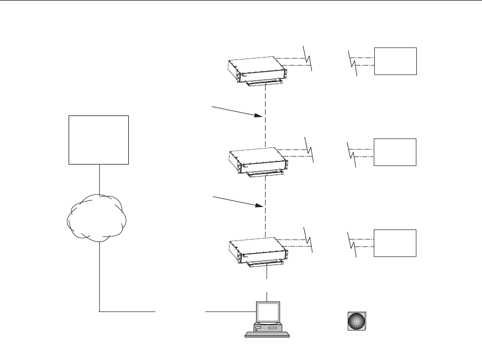
2.5 Remote NOC Interface
Remote communications between aNetwork Operations Center (NOC) and anetworked
grouping of multiple Digivance systems is supported by aremote NOC interface capability as
shown in Figure 5. The primary component of the remote NOC interface is aPC-type desktop
computer loaded with the Digivance Element Management System (DEMS) software. DEMS
provides the various control and monitoring functions required for remote management of
multiple Digivance systems through aNOC.
AController Area Network (CAN) port is provided on each HU so that up to twenty-four HU’s
can be networked together in daisy-chain fashion and controlled though the same DEMS
computer. The DEMS computer connects to the networked HU’s through the computer’s RS-
232 port #1. All HU’s can then be controlled through the same DEMS computer.
The NOC is connected to the DEMS computer through adata network. The DEMS computer’s
RS-232 port #2 interfaces with the data network equipment. The network equipment must be
capable of interfacing with an RS-232 ASCII interface port.
At the NOC, control and monitoring of the networked Digivance systems are effected through a
Network Element Manager (NEM) interface which requires only aVT100 terminal/emulator
for operation. The NEM interface language consists of simple ASCII text strings. All
communications are input as either SET or GET commands which result in ASCII text string
responses from the specified system or systems. The DEMS desktop computer may also be used
locally to manage the networked Digivance systems. Local operation is through the DEMS
software GUI.
HOST UNIT
LAPTOP WITH DEMS
(LOCAL INTERFACE)
LAPTOP WITH DEMS
(LOCAL INTERFACE)
18524-A
CD-ROM WITH DIGIVANCE
ELEMENT MANAGEMENT
SYSTEM (DEMS) SOFTWARE
REMOTE
UNIT
RS-232
RS-232
ADCP-75-150 • Preliminary Issue A • March 2003 • Section 1: Overview
Page 1-6
©2003, ADC Telecommunications, Inc.
Figure 1-5. Remote NOC Interface
3 SYSTEM FUNCTIONS AND FEATURES
This section describes various system level functions and features of the Digivance System.
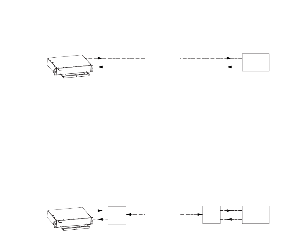
3.1 Fiber Optic Transport
In atypical Digivance 20 Watt system with asingle HU and RU, the HU is connected to the RU
over apair of single-mode optical fibers. One fiber is used to transport the forward path optical
signal. The other fiber is used to transport the reverse path optical signal. Because the optical
signal is digital, the input and output RF signal levels at the HU or the RU are not dependent on
the level of the optical signal or the length of the optical fiber. Adiagram of the fiber optic
transport system for atypical Digivance system is shown in Figure 1-6.The Digivance 20 Watt
system does not support reverse path diversity.
The maximum length of the optical fibers is dependent on the loss specifications of the optical
fiber and the losses imposed by the various connectors and splices. The system provides an
optical budget of 25 dB (typical) when used with 9/125 single-mode fiber.
DESKTOP COMPUTER WITH DEMS
(LOCAL AND REMOTE INTERFACE)
HOST UNIT
HOST UNIT
HOST UNIT
NETWORK
OPERATIONS
CENTER
(REMOTE
INTERFACE)
DATA
NETWORK
CONTROLLER
AREA
NETWORK
CONTROLLER
AREA
NETWORK
RS-232 ASCII
RS-232
18525-A
CD-ROM WITH DIGVANCE
ELEMENT MANAGEMENT
SYSTEM (DEMS) SOFTWARE
REMOTE
UNIT
REMOTE
UNIT
REMOTE
UNIT
ADCP-75-150 • Preliminary Issue A • March 2003 • Section 1: Overview
Page 1-7
©2003, ADC Telecommunications, Inc.
Figure 1-6. Standard Fiber Optic Transport
In some applications, it may be desirable or necessary to combine the forward path and reverse
path optical signals onto asingle optical fiber. This can be accomplished by using apair of
passive bi-directional Wavelength Division Multiplexers (WDM). The optical wavelengths used
in the system are 1550 nm for the forward path and 1310 nm for the reverse path. Because
different wavelengths are used for the forward and reverse paths, both signals can be combined
on asingle optical fiber. One WDM is mounted with the HU and the other WDM is mounted
with the RU as shown in Figure 1-7.The WDMs are available as accessory items.
Figure 1-7. Wavelength Division Multiplexer Application
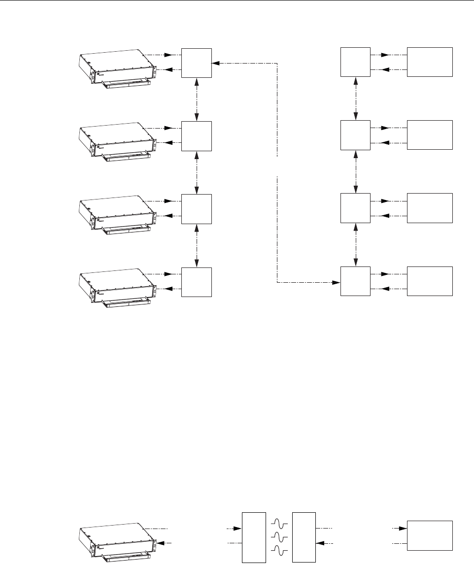
In some applications, it may be desirable or necessary to combine the forward and reverse path
optical signals from multiple HU’s and RU’s onto asingle optical fiber. This can be
accomplished by using an active Coarse Wavelength Division Multiplexer (CWDM) system. Up
to four 20 Watt systems may be configured to operate over asingle optical fiber. ACWDM
module is mounted with each HU and RU as shown in Figure 1-8.The CWDM system converts
the optical signal transmitted by each HU and RU to anew optical wavelength that is unique for
each unit. This allows the CWDM system to distinguish between the optical signals generated
by each HU and RU and therefore to distribute those signals to the appropriate destination. The
CWDM system is available separately as an accessory item.
HOST UNIT
18526-A
REMOTE
UNIT
FORWARD PATH
REVERSE PATH
FIBER OPTIC
LINK
HOST UNIT
18527-A
REMOTE
UNIT
FIBER OPTIC
LINK
WDM WDM
FORWARD AND
REVERSE PATH
ADCP-75-150 • Preliminary Issue A • March 2003 • Section 1: Overview
Page 1-8
©2003, ADC Telecommunications, Inc.
Figure 1-8. Coarse Wavelength Division Multiplexer Application
AFree Space Optics (FSO) system (that meets the Digivance system data rate performance and
BER requirements) may be used in applications where it is desirable or necessary to bridge an
open span and where it is impractical to lay afiber optic cable. One FSO transceiver unit may be
mounted on the HU side of the open span and the other FSO transceiver unit may be mounted
on the RU side of the open span. Asystem diagram of an FSO application is shown in
Figure 1-9.FSO systems are available from various equipment manufacturers.
Figure 1-9. Free Space Optics Application
18528-A
FIBER OPTIC
LINK
HOST UNIT 1
REMOTE
UNIT 1
CWDM
A
CWDM
A
HOST UNIT 2
REMOTE
UNIT 2
CWDM
B
CWDM
B
HOST UNIT 3
REMOTE
UNIT 3
CWDM
C
CWDM
C
HOST UNIT 4
REMOTE
UNIT 4
CWDM
D
CWDM
D
FORWARD AND
REVERSE PATH
HOST UNIT
18530-A
REMOTE
UNIT
FORWARD PATH
FSO
TX/RX
FSO
TX/RX
FREE SPACE OPTICS LINK
REVERSE PATH
FORWARD PATH
REVERSE PATH

ADCP-75-150 • Preliminary Issue A • March 2003 • Section 1: Overview
Page 1-9
©2003, ADC Telecommunications, Inc.
3.2 Control and Monitoring Software
The DEMS software supports control and monitoring functions for both the local and remote
service interfaces. The DEMS software is stored on aCD-ROM and shipped separately.
Software installation consists of copying the software files from the CD-ROM to adesignated
directory on the hard-drive of the DEMS computer.
The DEMS software is used to provision and configure the Digivance system for operation.
This includes selecting asitename, setting alarm thresholds, and setting forward and reverse
path RF gain adjustments. The DEMS software is also used to get alarm messages (individual or
summary), data measurements, or to upgrade the HU/RU system software. All control and
monitor functions (except software upgrade which can only be done using the DEMS software
GUI) can be effected using either the NOC/NEM interface or the DEMS software GUI.
3.3 Fault Detection and Alarm Reporting
LED indicators are provided on the front panel of the HU and on the front panels of the RU
modules to indicate if the system is normal or if afault is detected. In addition, normally open
and normally closed alarm contacts (for both major and minor alarms) are provided at the HU
for connection to acustomer-provided external alarm system. All alarms can also be accessed
through the NOC/NEM interface or the DEMS software GUI.
3.4 Powering
The HU is powered by ±24 or ±48 Vdc and must be hard-wired to alocal office battery power
source through afuse panel. Ascrew-down terminal strip is provided on the rear side of the HU
for the power connections.
The RU is powered by 120 or 240 Vac (50 or 60 Hz) and must be hard-wired to an AC power
source through a20 Amp breaker box. Athree-wire stub cable is provided for the AC power
connections. A120 Vac outlet should be installed near the RU for powering test equipment or
power tools. In certain applications, it may be necessary to install asurge protector (not
provided) in the AC power feed to prevent equipment damage from AC power spikes.
3.5 Equipment Mounting and Configuration
The HU is designed for mounting in anon-condensing indoor environment such as inside a
wiring closet or within an environmentally-controlled cabinet. The HU is intended for rack-
mount applications and may mounted in either a19- or 23-inch WECO or EIA equipment rack,
usually within 20 feet of the BTS.
The outdoor RU is designed for mounting in an outdoor environment. The outdoor RU consists
of aSpectrum Transport Module (STM), aLinear Power Amplifier (LPA) module, and aself-
contained cabinet which houses the modular components and protects them from the elements.
The RU cabinet is weather-tight but contact with salt-air mist should be avoided as it may
degrade the MTBF of the product. The outdoor cabinet can be mounted from aflat-vertical
surface, from autility pole (requires pole-mount kit), or mounted on apedestal. Slots are

ADCP-75-150 • Preliminary Issue A • March 2003 • Section 1: Overview
Page 1-10
©2003, ADC Telecommunications, Inc.
provided within the cabinet for the STM and LPA modules. Astorage spool is provided for
storing short lengths of excess fiber slack. Amounting slot is also provided for aWDM or
CWDM module (accessory items). Alighting protector for the antenna is included with the
outdoor cabinet to prevent equipment damage from lighting strikes.
The indoor RU is designed for mounting in anon-condensing indoor environment such as
inside awiring closet or within an environmentally-controlled cabinet. The indoor RU is
intended for rack-mount applications and may mounted in either a19- or 23-inch WECO or
EIA equipment rack. The indoor RU consists of aSpectrum Transport Module (STM), aLinear
Power Amplifier (LPA) module, and amounting shelf that supports the modular components.
The mounting shelf installs in the equipment rack. Slots are provided in the mounting shelf for
the STM and LPA modules. Astorage spool is provided for storing short lengths of excess fiber
slack. Aslot is also provided for mounting aWDM or CWDM module (accessory items).

ADCP-75-150 • Preliminary Issue A • March 2003 • Section 2: Description
Page 2-1
©2003, ADC Telecommunications, Inc.
SECTION 2: DESCRIPTION
1 INTRODUCTION. . . . . . . . . . . . . . . . . . . . . . . . . . . . . . . . . . . . . . . . . . . . . . . . . . . . . . . . . . . . . . . . . . . . . . . .2-3
2 HOST UNIT . . . . . . . . . . . . . . . . . . . . . . . . . . . . . . . . . . . . . . . . . . . . . . . . . . . . . . . . . . . . . . . . . . . . . . . . . . .2-3
2.1 Primary Components . . . . . . . . . . . . . . . . . . . . . . . . . . . . . . . . . . . . . . . . . . . . . . . . . . . . . . . . . . . . . .2-3
2.2 Mounting . . . . . . . . . . . . . . . . . . . . . . . . . . . . . . . . . . . . . . . . . . . . . . . . . . . . . . . . . . . . . . . . . . . . . .2-3
2.3 Fault Detection and Alarm Reporting . . . . . . . . . . . . . . . . . . . . . . . . . . . . . . . . . . . . . . . . . . . . . . . . . . .2-4
2.4 RF Signal Connections . . . . . . . . . . . . . . . . . . . . . . . . . . . . . . . . . . . . . . . . . . . . . . . . . . . . . . . . . . . . .2-4
2.5 RF Signal Level Adjustments. . . . . . . . . . . . . . . . . . . . . . . . . . . . . . . . . . . . . . . . . . . . . . . . . . . . . . . . .2-4
2.6 Propagation Delay . . . . . . . . . . . . . . . . . . . . . . . . . . . . . . . . . . . . . . . . . . . . . . . . . . . . . . . . . . . . . . . .2-5
2.7 Optical Connection . . . . . . . . . . . . . . . . . . . . . . . . . . . . . . . . . . . . . . . . . . . . . . . . . . . . . . . . . . . . . . .2-5
2.8 Controller Area Network Interface Connection . . . . . . . . . . . . . . . . . . . . . . . . . . . . . . . . . . . . . . . . . . . . .2-5
2.9 Service Interface Connection. . . . . . . . . . . . . . . . . . . . . . . . . . . . . . . . . . . . . . . . . . . . . . . . . . . . . . . . .2-5
2.10 Powering . . . . . . . . . . . . . . . . . . . . . . . . . . . . . . . . . . . . . . . . . . . . . . . . . . . . . . . . . . . . . . . . . . . . . .2-5
2.11 Cooling . . . . . . . . . . . . . . . . . . . . . . . . . . . . . . . . . . . . . . . . . . . . . . . . . . . . . . . . . . . . . . . . . . . . . . .2-6
2.12 User Interface . . . . . . . . . . . . . . . . . . . . . . . . . . . . . . . . . . . . . . . . . . . . . . . . . . . . . . . . . . . . . . . . . . .2-6
3 REMOTE UNIT OUTDOOR CABINET . . . . . . . . . . . . . . . . . . . . . . . . . . . . . . . . . . . . . . . . . . . . . . . . . . . . . . . . . .2-7
3.1 Primary Components . . . . . . . . . . . . . . . . . . . . . . . . . . . . . . . . . . . . . . . . . . . . . . . . . . . . . . . . . . . . . .2-8
3.2 Mounting . . . . . . . . . . . . . . . . . . . . . . . . . . . . . . . . . . . . . . . . . . . . . . . . . . . . . . . . . . . . . . . . . . . . . .2-9
3.3 STM and LPA Module Installation . . . . . . . . . . . . . . . . . . . . . . . . . . . . . . . . . . . . . . . . . . . . . . . . . . . . .2-9
3.4 WDM and CWDM Intallation . . . . . . . . . . . . . . . . . . . . . . . . . . . . . . . . . . . . . . . . . . . . . . . . . . . . . . . . .2-9
3.5 Fiber Optic Cable Entry. . . . . . . . . . . . . . . . . . . . . . . . . . . . . . . . . . . . . . . . . . . . . . . . . . . . . . . . . . . . .2-9
3.6 Antenna Cable Connection . . . . . . . . . . . . . . . . . . . . . . . . . . . . . . . . . . . . . . . . . . . . . . . . . . . . . . . . . 2-10
3.7 AC Power Wiring and Grounding . . . . . . . . . . . . . . . . . . . . . . . . . . . . . . . . . . . . . . . . . . . . . . . . . . . . . 2-10
3.8 Ventilation . . . . . . . . . . . . . . . . . . . . . . . . . . . . . . . . . . . . . . . . . . . . . . . . . . . . . . . . . . . . . . . . . . . . 2-10
3.9 User Interface . . . . . . . . . . . . . . . . . . . . . . . . . . . . . . . . . . . . . . . . . . . . . . . . . . . . . . . . . . . . . . . . . . 2-10
4 REMOTE UNIT INDOOR MOUNTING SHELF . . . . . . . . . . . . . . . . . . . . . . . . . . . . . . . . . . . . . . . . . . . . . . . . . . . . 2-12
4.1 Primary Components . . . . . . . . . . . . . . . . . . . . . . . . . . . . . . . . . . . . . . . . . . . . . . . . . . . . . . . . . . . . . 2-12
4.2 STM and LPA Module Installation . . . . . . . . . . . . . . . . . . . . . . . . . . . . . . . . . . . . . . . . . . . . . . . . . . . . 2-13
4.3 WDM and CWDM Installation . . . . . . . . . . . . . . . . . . . . . . . . . . . . . . . . . . . . . . . . . . . . . . . . . . . . . . . 2-13
4.4 Fiber Optic Cable Installation . . . . . . . . . . . . . . . . . . . . . . . . . . . . . . . . . . . . . . . . . . . . . . . . . . . . . . . 2-13
4.5 Antenna Cable Connections. . . . . . . . . . . . . . . . . . . . . . . . . . . . . . . . . . . . . . . . . . . . . . . . . . . . . . . . . 2-14
4.6 AC Power Wiring and Grounding . . . . . . . . . . . . . . . . . . . . . . . . . . . . . . . . . . . . . . . . . . . . . . . . . . . . . 2-14
4.7 User Interface . . . . . . . . . . . . . . . . . . . . . . . . . . . . . . . . . . . . . . . . . . . . . . . . . . . . . . . . . . . . . . . . . . 2-14
5 SPECTRUM TRANSPORT MODULE . . . . . . . . . . . . . . . . . . . . . . . . . . . . . . . . . . . . . . . . . . . . . . . . . . . . . . . . . . 2-15
5.1 Primary Components . . . . . . . . . . . . . . . . . . . . . . . . . . . . . . . . . . . . . . . . . . . . . . . . . . . . . . . . . . . . . 2-15
5.2 Mounting . . . . . . . . . . . . . . . . . . . . . . . . . . . . . . . . . . . . . . . . . . . . . . . . . . . . . . . . . . . . . . . . . . . . . 2-16
5.3 Fault Detection and Alarm Reporting . . . . . . . . . . . . . . . . . . . . . . . . . . . . . . . . . . . . . . . . . . . . . . . . . . 2-16
5.4 Antenna Cable Connection . . . . . . . . . . . . . . . . . . . . . . . . . . . . . . . . . . . . . . . . . . . . . . . . . . . . . . . . . 2-16
5.5 RF Signal Level Adjustment . . . . . . . . . . . . . . . . . . . . . . . . . . . . . . . . . . . . . . . . . . . . . . . . . . . . . . . . 2-17
5.6 Optical Connection . . . . . . . . . . . . . . . . . . . . . . . . . . . . . . . . . . . . . . . . . . . . . . . . . . . . . . . . . . . . . . 2-17
5.7 Service Interface Connection. . . . . . . . . . . . . . . . . . . . . . . . . . . . . . . . . . . . . . . . . . . . . . . . . . . . . . . . 2-17
5.8 Powering . . . . . . . . . . . . . . . . . . . . . . . . . . . . . . . . . . . . . . . . . . . . . . . . . . . . . . . . . . . . . . . . . . . . . 2-17
5.9 Cooling . . . . . . . . . . . . . . . . . . . . . . . . . . . . . . . . . . . . . . . . . . . . . . . . . . . . . . . . . . . . . . . . . . . . . . 2-17
Content Page

ADCP-75-150 • Preliminary Issue A • March 2003 • Section 2: Description
Page 2-2
©2003, ADC Telecommunications, Inc.
5.10 User Interface. . . . . . . . . . . . . . . . . . . . . . . . . . . . . . . . . . . . . . . . . . . . . . . . . . . . . . . . . . . . . . . . . . 2-17
6 LINEAR POWER AMPLIFIER . . . . . . . . . . . . . . . . . . . . . . . . . . . . . . . . . . . . . . . . . . . . . . . . . . . . . . . . . . . . . . 2-19
6.1 Primary Components . . . . . . . . . . . . . . . . . . . . . . . . . . . . . . . . . . . . . . . . . . . . . . . . . . . . . . . . . . . . . 2-19
6.2 Mounting . . . . . . . . . . . . . . . . . . . . . . . . . . . . . . . . . . . . . . . . . . . . . . . . . . . . . . . . . . . . . . . . . . . . . 2-20
6.3 Fault Detection and Alarm Reporting . . . . . . . . . . . . . . . . . . . . . . . . . . . . . . . . . . . . . . . . . . . . . . . . . . 2-20
6.4 Powering . . . . . . . . . . . . . . . . . . . . . . . . . . . . . . . . . . . . . . . . . . . . . . . . . . . . . . . . . . . . . . . . . . . . . 2-20
6.5 Cooling . . . . . . . . . . . . . . . . . . . . . . . . . . . . . . . . . . . . . . . . . . . . . . . . . . . . . . . . . . . . . . . . . . . . . . 2-21
6.6 User Interface. . . . . . . . . . . . . . . . . . . . . . . . . . . . . . . . . . . . . . . . . . . . . . . . . . . . . . . . . . . . . . . . . . 2-21
7 INTERFACE PANELS (ACCESSORY) . . . . . . . . . . . . . . . . . . . . . . . . . . . . . . . . . . . . . . . . . . . . . . . . . . . . . . . . . 2-22
8 WAVELENGTH DIVISION MULTIPLEXER (ACCESSORY). . . . . . . . . . . . . . . . . . . . . . . . . . . . . . . . . . . . . . . . . . . . 2-23
9 COARSE WAVELENGTH DIVISION MULTIPLER SYSTEM (ACCESSORY) . . . . . . . . . . . . . . . . . . . . . . . . . . . . . . . . . 2-24
10 DIGIVANCE ELEMENT MANAGEMENT SYSTEM . . . . . . . . . . . . . . . . . . . . . . . . . . . . . . . . . . . . . . . . . . . . . . . . . 2-25
10.1 Primary Components . . . . . . . . . . . . . . . . . . . . . . . . . . . . . . . . . . . . . . . . . . . . . . . . . . . . . . . . . . . . . 2-25
10.2 Service Interface Connection . . . . . . . . . . . . . . . . . . . . . . . . . . . . . . . . . . . . . . . . . . . . . . . . . . . . . . . 2-26
10.3 NOC Interface Connection . . . . . . . . . . . . . . . . . . . . . . . . . . . . . . . . . . . . . . . . . . . . . . . . . . . . . . . . . 2-26
10.4 DEMS Software User Interface . . . . . . . . . . . . . . . . . . . . . . . . . . . . . . . . . . . . . . . . . . . . . . . . . . . . . . 2-26
11 SPECIFICATIONS . . . . . . . . . . . . . . . . . . . . . . . . . . . . . . . . . . . . . . . . . . . . . . . . . . . . . . . . . . . . . . . . . . . . . 2-27
_________________________________________________________________________________________________________

ADCP-75-150 • Preliminary Issue A • March 2003 • Section 2: Description
Page 2-3
©2003, ADC Telecommunications, Inc.
1 INTRODUCTION
This section describes the basic components of the Digivance 800 MHz 20 Watt system
including the Host Unit (HU), the Remote Unit (RU), and the Digivance Element Management
System (DEMS). The RU is an assembly that consists of acabinet (for outdoor applications) or
mounting shelf (for indoor applications), aSpectrum Transport Module (STM), and aLinear
Power Amplifier (LPA) module. For clarity, the various components that comprise the RU are
described separately.
2 HOST UNIT
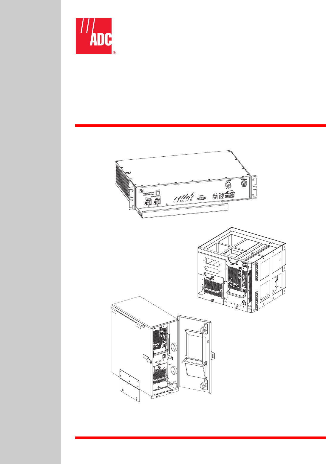
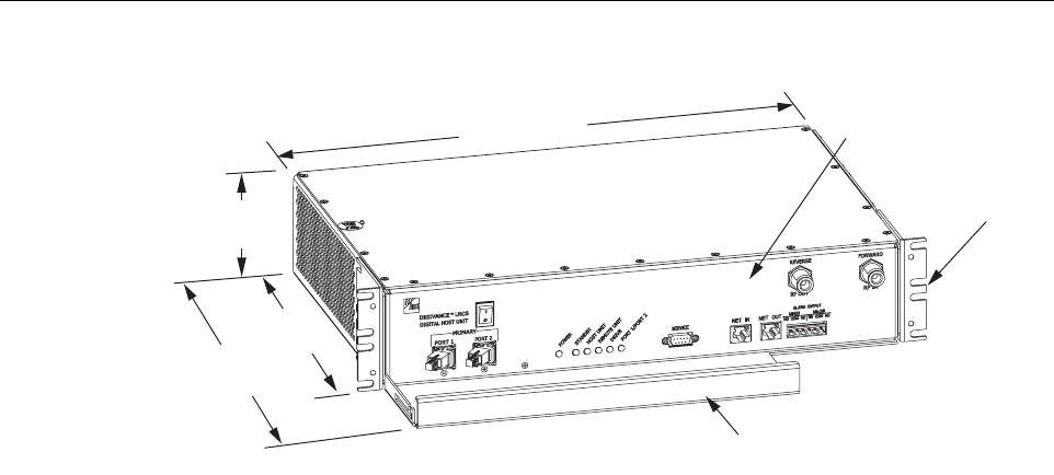
The HU, shown in Figure 2-1,serves as the BTS servicing unit for the Digivance system. The
HU provides the following basic functions:
• Provides an adjustable RF interface with the BTS.
• Provides afiber optic interface with the RU.
• Digitizes the forward path composite RF signal.
•Convertsthe digitized forward path RF signal to adigital optical signal.
•Convertsthe digitized reverse path optical signal to adigitized RF signal.
•Convertsthe digitized reverse path RF signal to acomposite RF signal.
• Signals alarm information to an external alarm system through relay contact closures
• Provides an RS-232 interface for connecting the DEMS computer.
• Provides aCAN interface for networking multiple HUs.
2.1 Primary Components
The HU consists of an electronic circuit board assembly and afan assembly that are mounted
within apowder-paint coated sheet metal enclosure. The enclosure provides amounting point
for the circuit board and fan assemblies and controls RF emissions. The only user-replaceable
component is the fan assembly. The HU is designed for use within anon-condensing indoor
environment such as inside awiring closet or cabinet. All controls, connectors, and indicators
(except the power terminal strip) are mounted on the HU front panel for convenient access.
Cable management functions for the coaxial cables and copper wiring are provided by acable
management tray that extends outward from the HU front panel.
2.2 Mounting
The HU is intended for rack-mount applications. Apair of reversible mounting brackets is
provided that allow the HU to be mounted in either a19-inch or 23-inch EIA or WECO
equipment rack. When installed, the front panel of the HU is flush with the front of the rack.
The cable management tray extends 3.9 inches (99 mm) beyond the front panel. Fasteners are
provided for securing the HU to the equipment rack.
ADCP-75-150 • Preliminary Issue A • March 2003 • Section 2: Description
Page 2-4
©2003, ADC Telecommunications, Inc.
Figure 2-1. Host Unit
2.3 Fault Detection and Alarm Reporting
The HU detects and reports various faults including host unit fault, optical fault, power fault,
temperature fault, and RF fault. Various front panel Light Emitting Diode (LED) indicators turn
from green to red or yellow if afault is detected. Aset of alarm contacts (normally open and
normally closed) are provided for reporting an alarm to an external alarm system when afault is
detected. Both major alarm (system operation seriously affected) and minor alarm (system
operation not affected or only slightly degraded) contacts are provided.
The status of the HU, the alarm state (major or minor), and other alarm information is
summarized and reported over the service interface, the CAN interface, and also over the optical
fiber to the RU. In addition, the state of the RU is received over the optical fiber and reported
over the service interface and the CAN interface. This detailed information may be accessed
remotely through the NOC/NEM interface or locally through the DEMS software GUI.
2.4 RF Signal Connections
The RF signal connections between the HU and the BTS are supported through two N-type
female connectors. One connector is used for the forward path RF signal. The other connector is
used for the reverse path RF signal. The 20 Watt system does not support adiversity reverse
path. In most installations, it is usually necessary to install aConditioning Panel and/or
Duplexing Panel (accessory items) to support the interface between the HU and the BTS. The
HU should be as close as possible to the BTS to minimize cable losses.
2.5 RF Signal Level Adjustments
The HU is equipped with several attenuators for adjusting the signal levels of the forward and
reverse path RF signals. The attenuators provide an attenuation adjustment range of 0to 31 dB
and can be set in 1dB increments. The attenuators are software controlled and are adjusted
through the NOC/NEM interface or the DEMS software GUI.
17.2 INCHES
(437 mm)
3.5 INCHES
(89 mm)
11.4 INCHES
(290 mm)
15.3 INCHES
(389 mm)
FRONT PANEL
CABLE MANAGEMENT
TRAY
MOUNTING
BRACKET
(BOTH SIDES)
18531-A

ADCP-75-150 • Preliminary Issue A • March 2003 • Section 2: Description
Page 2-5
©2003, ADC Telecommunications, Inc.
The host forward path attenuator adjusts the level of the input RF signal to the HU. Using the
forward path attenuator, an input signal with anominal composite signal level of –10 dBm to
–40 dBm can be adjusted to produce maximum power output. Additional external attenuation
is required if the input signal level is greater than –10 dBm.
The host reverse path attenuator adjusts the level of the output RF signal and will add from –1
dB of attenuation (attenuator set to 31 dB) to 30 dB of gain (attenuator set to 0dB) to the output
signal at the HU.
2.6 Propagation Delay
The HU forward, reverse, and diversity reverse path propagation delays may be adjusted in 0.1
µsec increments within arange of 0–63 µs. The propagation delay is software controlled and
may be adjusted through the NOC/NEM interface or the DEMS software GUI.
2.7 Optical Connection
Optical connections between the HU and the RU (STM) are supported through two SC-type
optical connector ports. One port is used for connecting the forward path optical signal and the
other port is used for connecting the primary reverse path optical signal.
2.8 Controller Area Network Interface Connection
Controller Area Network (CAN) interface connections between multiple HUs are supported by
apair of RJ-45 jacks. One of the jacks is designated as the network IN port and the other jack is
designated as the network OUT port. The CAN interface allows up to 24 HUs to be connected
together (in daisy-chain fashion) and controlled through asingle Digivance DEMS computer.
2.9 Service Interface Connection
The service interface connection between the HU and the Digivance DEMS computer is
supported by asingle DB-9 female connector. The service connector provides an RS-232 DTE
interface. When multiple HUs are networked together, the supporting DEMS computer may be
connected to the service connector of any one of the networked HUs.
2.10 Powering
The HU is powered by ±24 or ±48 Vdc power. The power is fed to the HU through ascrew-
down type terminal strip located on the rear side of the unit. Power to the HU must be supplied
through afuse panel such as the 20 position PowerWorx fuse panel (available separately). The
power circuit for each HU must be protected with a 3 Amp GMT fuse. An On/Off switch is
provided on the HU front panel.
ADCP-75-150 • Preliminary Issue A • March 2003 • Section 2: Description
Page 2-6
©2003, ADC Telecommunications, Inc.
2.11 Cooling
Continuous airflow for cooling is provided by dual fans mounted on the right side of the HU
housing. Aminimum of 3inches (76 mm) of clearance space must be provided on both the left
and right sides of the HU for air intake and exhaust. An alarm is provided if ahigh temperature
condition (>50º C/122º F) occurs. The fans may be field-replaced if either fan fails.
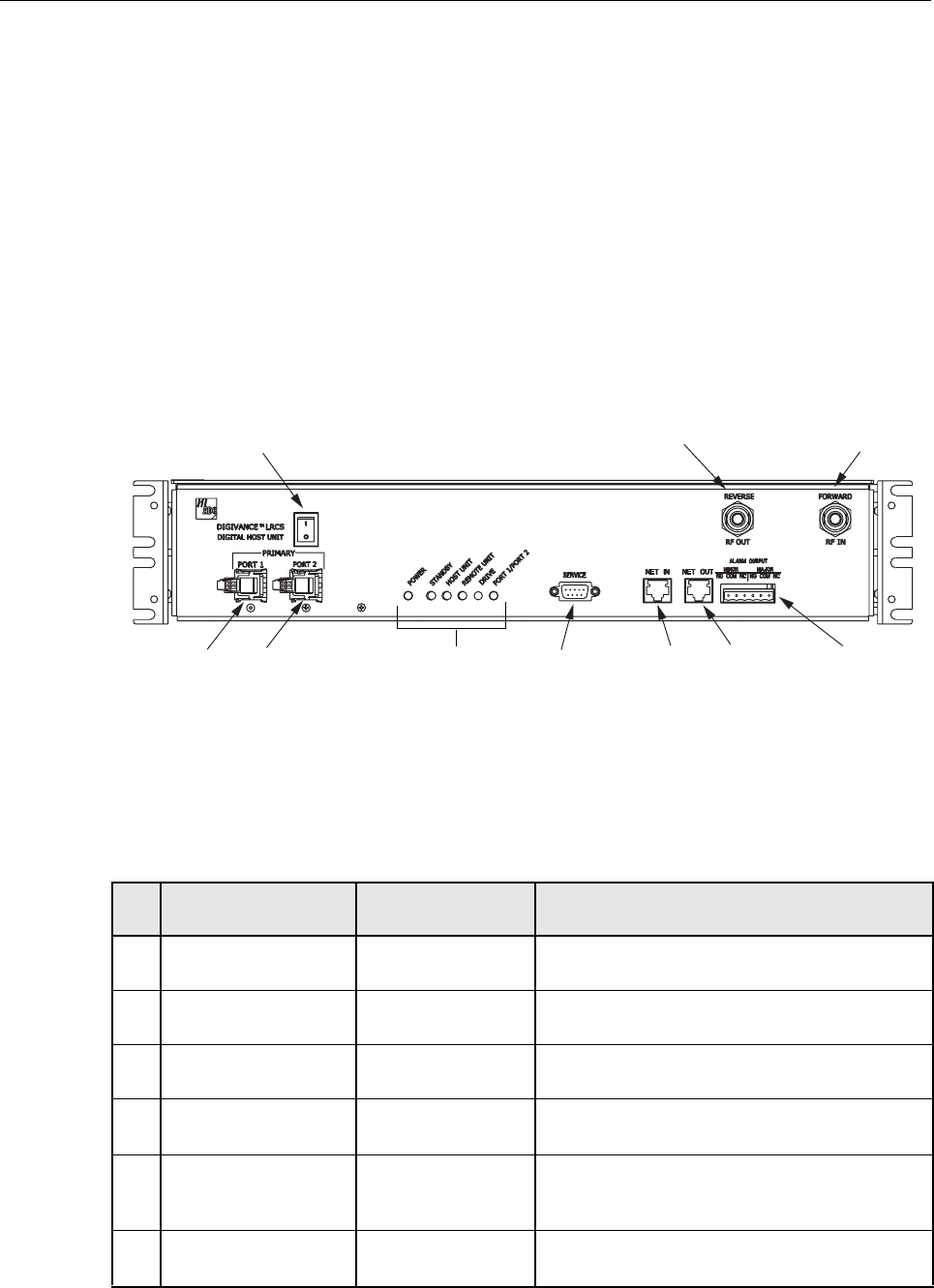
2.12 User Interface
The HU user interface consists of the various connectors, switches, terminals, and LEDs that are
provided on the HU front and rear panels. The user interface points are indicated in Figure 2-2
and described in Table 2-1.
Figure 2-2. Host Unit User Interface
Table 2-1. Host Unit User Interface
REF
NO
USER INTERFACE
DESIGNATION DEVICE FUNCTIONAL
DESCRIPTION
1I/0 On/Off rocker
switch Provides DC power on/off control.
2PORT1SCconnector
(single-mode) Output connection point for the forward path
optical fiber.
3PORT2SCconnector
(single-mode) Input connection point for the reverse path pri-
mary optical fiber.
4 POWER Multi-colored LED
(green/yellow)
Indicates if the HU is powered (green) or unpow-
ered (off). See Note.
5 STANDBY Multi-colored LED
(green/yellow/red)
Indicates if the system is in the Normal (off),
Standby (blinking green), Test (blinking red), or
Program Load (blinking yellow) state. See Note.
6 HOST UNIT Multi-colored LED
(green/yellow/red)
Indicates if the HU is normal (green), overheated
(yellow), or faulty (red). See Note.
(1) DC POWER
ON/OFF SWITCH
NOTE: SHOWN WITHOUT
CABLE MANAGEMENT TRAY
(2)
PORT 1 (3)
PORT 2 (REFERENCE
ITEMS 4 - 9)
LED INDICATORS
(10) SERVICE
INTERFACE
CONNECTOR
(11) NET IN
CONNECTOR (12) NET OUT
CONNECTOR (13) ALARM
OUTPUT
CONNECTOR
(14) REVERSE
RF OUT (15) FORWARD
RF IN
18532-A

ADCP-75-150 • Preliminary Issue A • March 2003 • Section 2: Description
Page 2-7
©2003, ADC Telecommunications, Inc.
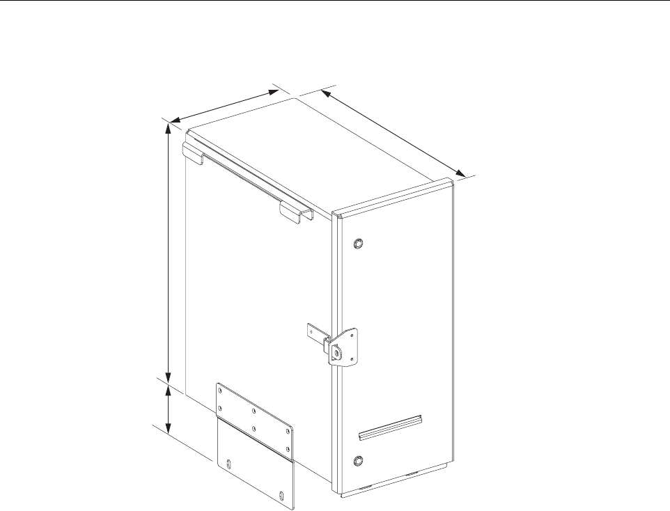
3 REMOTE UNIT OUTDOOR CABINET
The RU cabinet, shown in Figure 2-3,is aNEMA-3R enclosure (with removable dust filters) that
provides the following basic functions:
• Houses the various electronic modules (STM and LPA) and accessories (WDM or
CWDM) and protects them from the weather.
• Provides electrical interface connections for the STM and LPA modules.
• Provides ventilation openings to allow for entry of cool air and the escape of heated air.
• Provides apoint for connecting the antenna cable, fiber optic cable, AC power wiring, and
ground cable.
• Provides apoint for connecting astandard AC power conduit fitting.
• Provides lightning protection
• Provides limited storage for fiber optic pigtails and patch cords.
• Provides electrical connections for the CWDM
7REMOTEUNIT Multi-colored LED
(green/yellow/red)
Indicates if no alarms (green), aminor alarm
(yellow), or amajor alarm (red) is reported by the
RU. See Note.
8 DRIVE Multi-colored LED
(green/yellow/red)
Indicates if the level of the RF input signal to the
HU is normal (green), low (yellow), or high
(red). See Note.
9PORT1/PORT 2 Multi-colored LED
(green/yellow/red)
Indicates if the reverse path optical signal
received from the RU is normal (green) or if
errors are detected (red). See Note.
10 SERVICE DB-9 connector
(female) Connection point for the RS-232 service inter-
face cable.
11 NET IN RJ-45 jack (female) Connection point for CAN interface input cable.
12 NET OUT RJ-45 jack (female) Connection point for CAN interface output cable.
13 ALARM OUTPUT Screw-type terminal
connector (14–26
AWG)
Connection point for an external alarm system.
Includes normally open (NO), normally closed
(NC), and common (COM) wiring connections.
14 REVERSE RF OUT N-type female RF
coaxial connector Output connection point for the primary reverse
path RF coaxial cable.
15 FORWARD RF IN N-type female RF
coaxial connector Input connection point for the forward path RF
coaxial cable.
POWER 24–48 VDC
(Rear side -not shown) Screw-type terminal
strip Connection point for the DC power wiring.
Note: Amore detailed description of LED operation is provided in Section 5.
Table 2-1. Host Unit User Interface, continued
REF
NO
USER INTERFACE
DESIGNATION DEVICE FUNCTIONAL
DESCRIPTION
ADCP-75-150 • Preliminary Issue A • March 2003 • Section 2: Description
Page 2-8
©2003, ADC Telecommunications, Inc.
Figure 2-3. Remote Unit Outdoor Cabinet
3.1 Primary Components
The RU outdoor cabinet consists of the enclosure, mounting slots for the STM and LPA modules,
amounting slot for the either the WDM or CWDM (accessory item), lightning protector, and two
fiber storage spools. The RU cabinet is designed for use in an outdoor environment. Opening the
hinged door provides full height and width access to the interior of the enclosure to facilitate
module and cable installation.
The enclosure is constructed of heavy gauge aluminum and is painted putty white for corrosion
protection. Connection and/or entry points are provided in the bottom of the enclosure for the
antenna coaxial cable, fiber optic cable, and AC power cable. Vent openings are provided in the
door, bottom, and rear side of the enclosure to permit air exchange for cooling. The RU cabinet
is weather-tight but contact with salt-air mist should be avoided as it may degrade the Mean
Time Between Failure (MTBF) of the product. Drain holes in the bottom of the cabinet allow
any moisture that does enter the cabinet to drain out. The cabinet door is equipped with asturdy
latch so that the enclosure may be padlocked to prevent unauthorized entry. Adoor open switch
is provided so that amajor alarm is generated whenever the cabinet door is opened.
NOTE: EACH DIMENSION INCLUDES AN
ALLOWANCE FOR ANY COMPONENT THAT
PROJECTS OUTWARD FROM THE CABINET
SUCH AS THE DOOR LATCH.
18564-A
3.30 INCHES
(109 MM)
22.25 INCHES
(565 MM)
10.13 INCHES
(257 MM)
20.75 INCHES
(527 MM)

ADCP-75-150 • Preliminary Issue A • March 2003 • Section 2: Description
Page 2-9
©2003, ADC Telecommunications, Inc.
3.2 Mounting
The RU cabinet may be mounted on aflat vertical surface (such as the side of building) on a
utility pole, or on apedestal. Aspecial mounting bracket is provided with each enclosure.
Installation consists of securing the bracket to the mounting surface and then hanging the
enclosure from the bracket. The mounting bracket may be attached to avariety of surfaces such
as wood, concrete, or masonry. Various fasteners including hex-head capscrews, tee-nuts, and
concrete anchors are provided. Apedestal-mounting kit (accessory item) is available for
mounting the cabinet on aflat horizontal surface.
3.3 STM and LPA Module Installation
Two mounting slots are provided within the RU cabinet for installing the STM and LPA
modules. The mounting slots include tracks that guide each module into the installed position.
Separate mounting slots are provided for STM and LPA modules. Two D-sub connectors (one
male, one female) are located at the rear of each mounting slot. Each mounting slot connector
mates with acorresponding D-sub connector located on the rear side of each module. Awiring
harness links the mounting slot connectors together. The connectors and the attached wiring
harness provide the electrical interface between the STM and LPA modules. The modules are
held in the installed position with captive screws.
3.4 WDM and CWDM Intallation
Amounting slot is provided within the RU cabinet for installing aWDM or CWDM module
(accessory items). Each module is equipped with push-pull type fasteners for securing the
module to the mounting slot. Apower cable is included with the cabinet for providing power
when aCWDM module is installed. Afiber storage spool is provided for storing excess pigtail
and/or patch cord slack.
3.5 Fiber Optic Cable Entry
Aplastic cord connector is provided in the exterior bottom side of the RU cabinet for routing a
fiber optic cable into the enclosure. The cord connector provides cable strain relief and a
watertight seal at the fiber optic cable entry point. As the connector nut is tightened, asoft
neoprene bushing compresses to tightly grip the cable without applying excessive force to the
fibers. The cord connector can accommodate cables that range from 0.375 to 0.875 inches (10 to
23 mm) in diameter. Aspool is provided directly above the fiber optic cable entry hole for
storing excess pigtail slack.
In atypical installation, the connectorized end of amulit-fiber outside plant cable is routed into
the enclosure through the cord connector and the individual fibers are broken out into pigtails.
The pigtails are connected to the optical ports on the STM and the excess pigtail slack is stored
on the fiber storage spool. The stub end of the cable is routed to an external splice enclosure (not
provided) for splicing to the fiber optic cable.

ADCP-75-150 • Preliminary Issue A • March 2003 • Section 2: Description
Page 2-10
©2003, ADC Telecommunications, Inc.
3.6 Antenna Cable Connection
An N-type female connector is provided on the exterior bottom side of the RU cabinet for
connecting the primary antenna coaxial cable. The exterior connector is on the surge side of a
lightning protector that is mounted on the interior bottom side of the enclosure. On the inside of
the enclosure, asecond N-type female connector is provided on the protected side of the
lightning protector. Acoaxial jumper cable (included with the enclosure) is used for connecting
the protected side N-type connector to the ANTENNA port on the STM.
3.7 AC Power Wiring and Grounding
The RU outdoor cabinet is equipped with a3-foot long stub cable for the AC power
connections. The AC power cable provides three wire leads (Load, Neutral, and Ground) that
must be connected to a120 or 240 Vac power source. The AC power cable exits the cabinet
though a3/4-inch NPT threaded hole located on the bottom of the cabinet. The threaded hole
accepts astandard 3/4-inch AC conduit fitting. A3/4-inch to 1/2-inch reducer is also included if
1/2-inch conduit is preferred over 3/4-inch conduit.
From the exit point in the bottom of the cabinet, the AC power cable must be routed through
conduit to an external AC junction box (not provided) where it can be connected to the AC
power wiring. The junction box should be located within two feet of the cabinet and should be
equipped with a120 Vac outlet for powering test equipment and/or power tools. If AC power
spikes are likely to occur, the junction box should also include asurge protector to protect the
equipment from damage.
Three wire nuts are included with the cabinet for completing the AC power wiring connections.
The junction box wiring should be connected to the AC power source through a20 Amp breaker
box (not provided). All AC power wiring should be run within conduit. Agrounding lug is
provided on the underside of the enclosure for connecting aseparate grounding wire directly to
the cabinet.
3.8 Ventilation
Vent openings are provided in the door, on the bottom, and on the rear side of the RU cabinet to
permit air exchange for cooling. Air enters the cabinet through the openings in the door and
bottom. Filters remove dirt particles so that only clean air enters the enclosure. Both the STM
and LPA have cooling fans. The STM has arear mounted fan that pulls air through the module
and exhausts it toward the rear of the enclosure. The LPA has afan on the front that draws air
into the module and exhausts it toward the rear of the enclosure. The heated air exits through an
opening in the rear side of the enclosure.
3.9 User Interface
The RU cabinet user interface consists of the various connectors, fittings, mounting slots, and
switches that are provided on both the interior and exterior of the enclosure. The user interface
points are indicated in Figure 2-4 and described in Table 2-2.
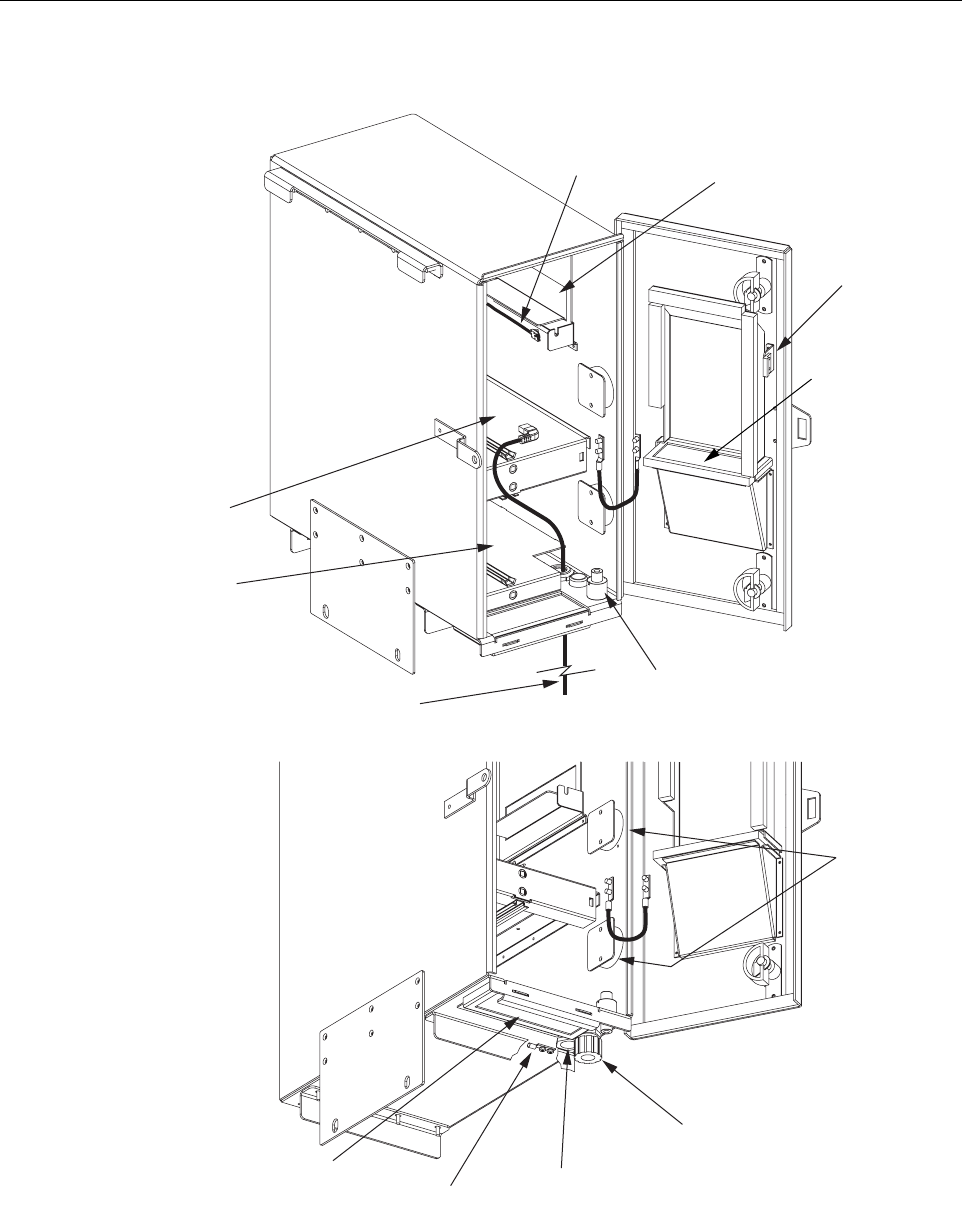
ADCP-75-150 • Preliminary Issue A • March 2003 • Section 2: Description
Page 2-11
©2003, ADC Telecommunications, Inc.
Figure 2-4. Remote Unit Outdoor Cabinet User Interface
(1) AIR INLET
FILTER
(1) AIR INLET
FILTER
18563-A
(2) AC POWER
CABLE
(3) DOOR SWITCH
(5) STM
MOUNTING
SLOT
(4) LPA
MOUNTING
SLOT
(6) WDM/CWDM
MOUNTING SLOT
(8) FIBER
SLACK SPOOLS
(12) GROUNDING
LUG
(11) 3/4-INCH NPT
THREADED HOLE
(10) FIBER CABLE
CONNECTOR
(7) CWDM POWER
CORD
BOTTOM VIEW
OF CABINET
(9) LIGHTNING
PROTECTOR

ADCP-75-150 • Preliminary Issue A • March 2003 • Section 2: Description
Page 2-12
©2003, ADC Telecommunications, Inc.
4 REMOTE UNIT INDOOR MOUNTING SHELF
The RU indoor mounting shelf, shown in Figure 2-5,is arack-mountable framework that
provides the following basic functions:
• Supports the various electronic modules (STM and LPA) and accessories (WDM or
CWDM) for mounting within astandard 19-inch, WECO or EIA, equipment rack.
• Provides the electrical interface connections for the STM and LPA modules.
• Provides an AC power cord for powering the STM module
• Provides DC power connections for the CWDM module.
4.1 Primary Components
The RU indoor mounting shelf is arack-mountable frame assembly that provides mounting
slots for the STM, LPA, WDM (accessory), and CWDM (accessory) modules. The indoor
mounting shelf is designed for mounting in astandard 19-inch, EIA or WECO, equipment rack.
The frame assembly is constructed of steel and is painted putty white for corrosion protection.
Table 2-2. Remote Unit Cabinet User Interface
REF
NO DEVICE FUNCTIONAL DESCRIPTION
1Airinlet filters Reusable filters that prevent the entry of dirt particles when out-
side air is pulled into the cabinet for cooling.
2ACpower cord Provides AC power to the STM.
3Doorswitch Indicates to the fault detection and alarm reporting system if the
cabinet door is open (major alarm) or closed.
4LPAmounting slot Provides amounting point for the LPA module.
5STMmounting slot Provides amounting point for the STM module.
6WDM/CWDMmounting
slot Provides amounting point for either the WDM or CWDM mod-
ule.
7CWDMpower cord Provides DC power to the CWDM module.
8Fiberslack spools Provide astorage place for excess fiber pigtail and patch cord
slack.
9 Lightning protector Provides lightning surge protection for the antenna connection.
10 Fiber cable connector Provides both an entry point and strain relief for the fiber optic
cable.
11 3/4-inch NPT threaded hole Provides aconnection point for a3/4-inch AC conduit fitting.
121 Grounding lug Provides aconnection point for an external grounding cable.
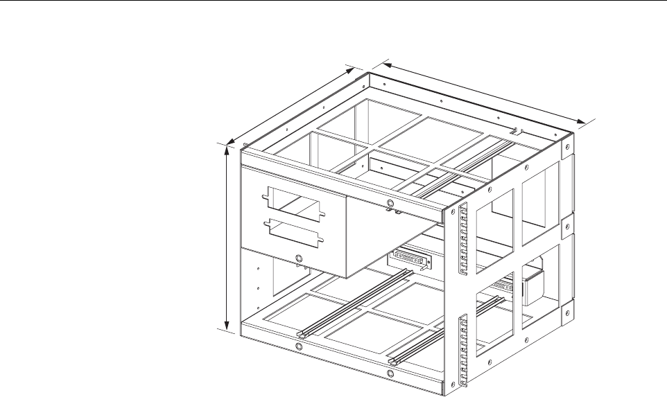
ADCP-75-150 • Preliminary Issue A • March 2003 • Section 2: Description
Page 2-13
©2003, ADC Telecommunications, Inc.
Figure 2-5. Remote Unit Indoor Mounting Shelf
4.2 STM and LPA Module Installation
Two mounting slots are provided within the indoor mounting shelf for installing the STM and
LPA modules. The mounting slots include tracks that guide each module into the installed
position. Separate mounting slots are provided for STM and LPA modules. Two D-sub
connectors (one male, one female) are located at the rear of each mounting slot. Each mounting
slot connector mates with acorresponding D-sub connector located on the rear side of each
module. Awiring harness links the mounting slot connectors together. The connectors and the
attached wiring harness provide the electrical interface between the STM and LPA modules.
The modules are held in the installed position with captive screws.
4.3 WDM and CWDM Installation
Mounting slots are provided in the indoor mounting shelf for installing aWDM or CWDM
module (accessory items). Each module is equipped with push-pull type fasteners for securing
the module to the mounting slot. Apower cable is included with the mounting shelf for
supplying DC power when aCWDM module is installed.
4.4 Fiber Optic Cable Installation
Fiber optic cables and patch cords should be routed to the indoor mounting shelf using existing
fiber management systems. All fiber optic connections are made directly with the STM, WDM,
or CWDM modules. It is recommended that some provision be made at the mounting shelf for
storing excess patch cord slack.
18565-A
14.15 INCHES
(359 MM)
15.6 INCHES
(396 MM)
17.39 INCHES
(442 MM)
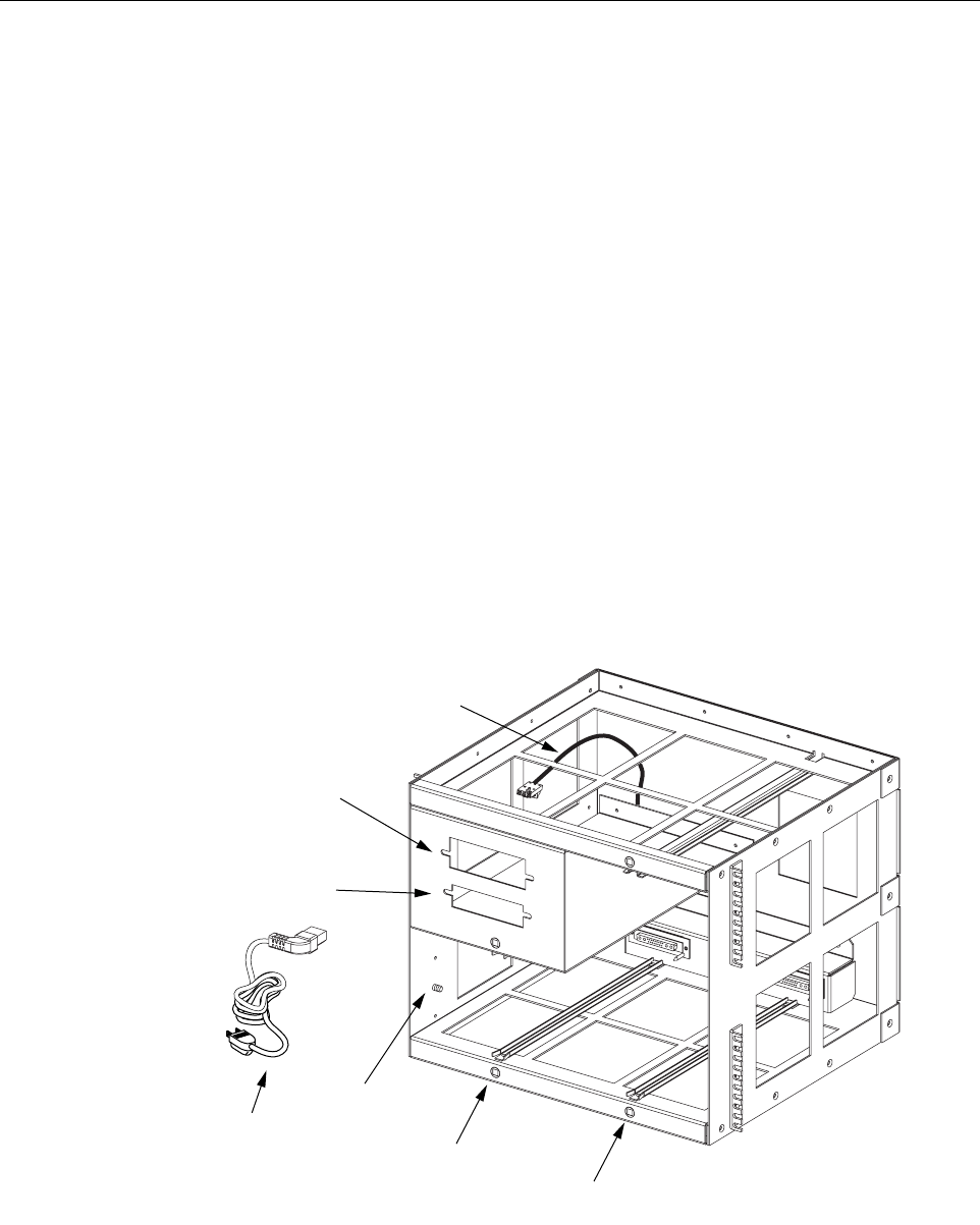
ADCP-75-150 • Preliminary Issue A • March 2003 • Section 2: Description
Page 2-14
©2003, ADC Telecommunications, Inc.
4.5 Antenna Cable Connections
The antenna cable should be routed to the indoor mounting shelf for connection to the STM
module. If lightning protection is required, it is recommended that alightning protection device
be installed near the point where the antenna cable enters the building or enclosure.
4.6 AC Power Wiring and Grounding
Astandard three-conductor AC power cord is provided with the indoor mounting shelf for the
AC power connections. The receptacle end of the power cable connects to the AC connector on
the STM. The plug end of the power cable connects to astandard 120 Vac outlet. If AC power
spikes are likely to occur, asurge protector should be installed to protect the equipment from
damage. Agrounding stud is provided on the left side of the mounting shelf for connecting a
separate grounding wire directly to the mounting shelf chassis.
4.7 User Interface
The RU mounting shelf user interface consists primarily of the mounting slots and AC and DC
power cables. The user interface points are indicated in Figure 2-6 and described in Table 2-3.
Figure 2-6. Remote Unit Indoor Mounting Shelf User Interface
18642-A
(1) STM MOUNTING
SLOT
(2) LPA MOUNTING
SLOT
(4) AC POWER
CABLE
(5) WDM MOUNTING
SLOT
(6) CWDM MOUNTING
SLOT
(7) CWDM DC
POWER CABLE
(3) GROUNDING
STUD