ADC Telecommunications DLC0802A Digivance 800 MHz 20 Watts System User Manual 75150
ADC Telecommunications Inc Digivance 800 MHz 20 Watts System 75150
Contents
manual3
ADCP-75-150 • Preliminary Issue A • March 2003 • Section 2: Description
Page 2-27
©2003, ADC Telecommunications, Inc.
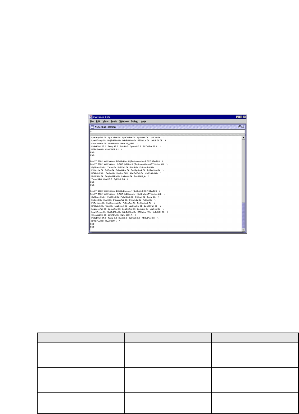
The NOC/NEM interface is acommand line interface that is presented at an NOC terminal. The
NOC/NEM interface is used for remote control and monitoring operations. The NOC/NEM
interface consists of ASCII text strings that are input as SET or GET commands which are
followed by the action or information required. Atext string response is received from the
specified system or systems to confirm the requested action or to report the requested
information. Examples of several typical NOC-NEM interface commands and the responses
received are shown in Figure 2-19.The NOC/NEM interface requires only aVT100 terminal/
emulator or aPC-type computer that is loaded with acommunication software such as
Procomm Plus. While primarily intended for use at the NOC, the NOC/NEM interface
commands may also be input from the DEMS computer.
Figure 2-19. NOC/NEM Interface Typical Commands
11 SPECIFICATIONS
Refer to Table 2-6 for the Digivance 800 MHz 20 Watt System nominal specifications. All
specifications apply after afive minute warm-up period.
Table 2-6. 800 MHz 20 Watt System Nominal Specifications
PARAMETER SPECIFICATION REMARKS
Optical - Host and Remote Unit
Fiber type 9/125, single-mode
Number of fibers required
Direct
With WDM
2
1The wavelength division multi-
plexer (WDM) is an accessory.
Forward path wavelength 1550 nm
Reverse path wavelength 1310 nm
FCC ID: F8I-DLC0802A User Manual - Part 3

ADCP-75-150 • Preliminary Issue A • March 2003 • Section 2: Description
Page 2-28
©2003, ADC Telecommunications, Inc.
Optical transmit power output
Host Unit
Remote Unit 0dBm
+2 dBm
Optical budget 25 dB For optical BER of 10–6
Optical Receive Input –15 dBm
Optical connectors Industry standard SC Host, remote, and WDM
RF Forward Path - 800 MHz
Bandwidth
Aband
Bband
11 and 1.5 MHz
10 and 2.5 MHz
Frequency range
Aband
Bband 869–880 and 890–891.5 MHz
880–890 and 891.5–894 MHz
Out-of-band emissions
Primary
Secondary (see Note 1)
–13 dBm per 1MHz bandwidth
from 10 kHz to 20 GHz
–98 dBm per 100 kHz from 824
to 849 MHz and from 1850 to
1910 MHz
Gain of forward path
(Host input to Remote antenna
port)
80.5 dB at band center, room
temperature, and 0dB attenua-
tion setting
Includes power amplifier.
Gain flatness
Band flatness
Channel flatness ±1.5 dB across freq. range
±1 dB variation across any 1.25
MHz channel
Gain variation ± 3dB over temp and unit-to-
unit
Out-of-band rejection –40 dB at >±17.5 MHz from
881.5 MHz
Propagation delay 2.2 µs Excludes fiber delay
Configurable propagation delay
Range
Step size Up to 63 µs
0.1µs
Plus standard propagation delay
Spurious
In-band self generated
Free dynamic range –13 dBm at remote output
60 dB at 30 kHz bandwidth
Transmit peak-to-average 10 dB
Two-tone Intermodulation –55 dBc at remote output Two tones at 5Watts each
CDMA Intermodulation
885 kHz to 1.25 MHz
1.25 to 1.98 MHz
1.98 to 2.25 MHz
–45 dBc per 30 kHz
–8 dBm per 30 kHz
–55 dBc per 30 kHz Absolute level
Table 2-6. 800 MHz 20 Watt System Nominal Specifications, continued
PARAMETER SPECIFICATION REMARKS

ADCP-75-150 • Preliminary Issue A • March 2003 • Section 2: Description
Page 2-29
©2003, ADC Telecommunications, Inc.
Nominal composite RF input
signal level –40 dBm at 0dB attenuation
–10 dBm at max. attenuation An input signal level of –40 dBm
provides maximum output power
Configurable input level
Range
Step size 30 dB
1 ± 0.5 dB ±10% of attenuation
monotonic
Composite RF Output power 40.5 dBm (11 Watts) at remote
antenna port with –40 dBm input 20 Watts at power amplifier out-
put
Configurable RF Output
Range
Step size 30 dB at remote unit
1±0.5 dB ±10% of attenuation
monotonic
Transmit path insertion loss 2.5 dB
RF Reverse Path - 800 MHz
Bandwidth
Aband
Bband 11 and 1.5 MHz
10 and 2.5 MHz
Frequency range
Aband
Bband 824–835 and 845–846.5 MHz
835–845 and 846.5–849 MHz
In band spurs (caused by an indi-
vidual out-of-band signal) –75 dBc (1 MHz to 20 GHz and
>10 MHz out-of-band)
–120 dBc (1930 to 1990 MHz)
–120 dBc (869 to 894 MHz) Required for dual band
Propagation delay 2.2 µs Excludes fiber delay
Configurable propagation delay
Range
Step size Up to 63 µs
0.1µs
Plus standard propagation delay
Gain flatness
Band flatness
Channel flatness ±1.5 dB across frequency range
±1 dB variation across any 1.25
MHz channel
Gain of reverse path
Overall gain
Gain variation
30 dB at band center at room
temperature
3dB over temperature
ALC not invoked
ALC not invoked
Out-of-band rejection –40 dB at >±17.5 MHz from
836.6 MHz ALC not invoked
Spurious (in-band self gener-
ated) –110 dBm referred to input ALC not invoked
Intermodulation –62 dBc two tones at –50 dBm
System noise figure 9 dB ALC not invoked
Table 2-6. 800 MHz 20 Watt System Nominal Specifications, continued
PARAMETER SPECIFICATION REMARKS

ADCP-75-150 • Preliminary Issue A • March 2003 • Section 2: Description
Page 2-30
©2003, ADC Telecommunications, Inc.
Configurable RF output
Range
Step size 30 dB
1±0.5 dB ±10% of attenuation
monotonic
Blocking dynamic range 70 dB
Level limiting ALC threshold –40 dBm dB instantaneous
Level limiting ALC range 30 dB
RF Forward and Reverse Path
Modulation Accuracy
Service/Mod Type/Parameter
TDMA/n/4-DQSK/rms EVM
GSM/GMSK/rms phase error
EDGE/8PSK/rms EVM
EIA-97D/CDMA/rho factor
7%
4%
7%
.97%
Physical/Environmental/
Electrical - Host Unit
Dimensions (H×W×D) 3.5 × 17.2 × 15.3 inches
(89 ×437 ×389 mm) Dimension for width does not
include the mounting brackets
which can be installed for either
19- or 23-inch racks.
Mounting 19- or 23-inch rack EIA or WECO
Weight 18 lbs. (8.2 kg)
Weather resistance Indoor installation only
Operating temperature 0º to 50º C(32º to 122º F)
Storage temperature –40º to 70º C(–40º to 158ºF)
Humidity 10% to 90% No condensation
External alarm connector Screw-type terminals NO and NC relay contacts
DC power connector Screw-type terminal strip
RF coaxial cable connectors N-type (female)
Service connector DB-9 (female) RS-232 DTE interface
CAN connectors RJ-45 jack
Power input ± 24 or ±48 Vdc
Power consumption 55 watts
Current rating 1 Amp at –48 Vdc
Reliability at 25ºC MTBF 80,000 hours Excluding fans
Table 2-6. 800 MHz 20 Watt System Nominal Specifications, continued
PARAMETER SPECIFICATION REMARKS

ADCP-75-150 • Preliminary Issue A • March 2003 • Section 2: Description
Page 2-31
©2003, ADC Telecommunications, Inc.
Physical/Environmental/
Electrical - Remote Unit Outdoor
Cabinet
Cabinet dimensions (H×W×D) 25.6 × 10.13 × 20.75 inches
(674 ×257 ×527 mm)
Mounting Wall, pole, or pedestal Pedestal mounting requires ped-
estal mount kit. (accessory)
Weight 80 lbs (36.3 kg) Includes modules
Weather resistance NEMA-3R, removable dust filter
Operating temperature –30º to 50º C(–22º to 122º F)
Storage temperature –40º to 70º C(–40º to 158ºF)
Humidity 10% to 90% No condensation
External alarm connector Screw-type terminals External alarm inputs
AC power connection 3/4- or 1/2-inch conduit Per local code or practice.
Antenna cable connector N-type female
Fiber optic cable size 0.375 to 0.875 inch (10 to 22
mm) diameter cable 9/125, single-mode
Lightning protection 20 kA IEC 1000-4-5 8/20 µs
waveform
Service connector DB-9 female (on STM) RS-232 DTE interface
Power input 120 or 240 VAC , 50 or 60 Hz Operation on 240 Vac requires
removal of the 120 Vac outlet.
Power consumption 1200 watts
Current rating 9 Amps at 120 Vac
Reliability at 25ºC MTBF 50,000 hours Excluding fans and air filter
Physical/Environmental/
Electrical - Remote Unit Indoor
Mounting Shelf
Mounting Shelf dimensions
(H×W×D) 14.15 × 17.39 × 15.6 inches
(359 ×442 ×396 mm)
Mounting 19-inch equipment rack WECO or EIA
Weight 50 lbs. (22.7 kg) Includes modules
Operating temperature –30º to 50º C(–22º to 122º F)
Storage temperature –40º to 70º C(–40º to 158ºF)
Humidity 10% to 90% No condensation
External alarm connector Screw-type terminals (on STM) External alarm inputs
AC power connection AC power cord with standard 3-
prong 120 Vac plug.
Table 2-6. 800 MHz 20 Watt System Nominal Specifications, continued
PARAMETER SPECIFICATION REMARKS

ADCP-75-150 • Preliminary Issue A • March 2003 • Section 2: Description
Page 2-32
©2003, ADC Telecommunications, Inc.
Note 1: Required for co-located sites such as dual band. Otherwise, the emissions from one unit
can limit the sensitivity of the other.
Antenna cable connector N-type female (on STM)
Fiber optic cable connector SC-type (on STM)
Service connector DB-9 female (on STM) RS-232 DTE interface
Power input 120 or 240 VAC , 50 or 60 Hz Operation on 240 Vac requires
power cord with 240 Vac plug.
Power consumption 1200 watts
Current rating 9 Amps at 120 Vac
Reliability at 25ºC MTBF 50,000 hours Excluding fans and air filters
Table 2-6. 800 MHz 20 Watt System Nominal Specifications, continued
PARAMETER SPECIFICATION REMARKS

ADCP-75-150 • Preliminary Issue A • March 2003 • Section 3: Host Unit Installation
Page 3-1
©2003, ADC Telecommunications, Inc.
SECTION 3: HOST UNIT INSTALLATION
1 BEFORE STARTING INSTALLATION . . . . . . . . . . . . . . . . . . . . . . . . . . . . . . . . . . . . . . . . . . . . . . . . . . . . . . . . . .3-1
1.1 Tools and Materials . . . . . . . . . . . . . . . . . . . . . . . . . . . . . . . . . . . . . . . . . . . . . . . . . . . . . . . . . . . . . . .3-1
1.2 Unpacking and Inspection . . . . . . . . . . . . . . . . . . . . . . . . . . . . . . . . . . . . . . . . . . . . . . . . . . . . . . . . . . .3-2
2 OUTDOOR CABINET OSP FIBER CABLE INSTALLATION GUIDELINES . . . . . . . . . . . . . . . . . . . . . . . . . . . . . . . . . . . .3-2
3 WDM MOUNTING PROCEDURE (OPTIONAL ACCESSORY) . . . . . . . . . . . . . . . . . . . . . . . . . . . . . . . . . . . . . . . . . . .3-4
4 HU MOUNTING PROCEDURE . . . . . . . . . . . . . . . . . . . . . . . . . . . . . . . . . . . . . . . . . . . . . . . . . . . . . . . . . . . . . . .3-6
5 CHASSIS GROUND CONNECTION . . . . . . . . . . . . . . . . . . . . . . . . . . . . . . . . . . . . . . . . . . . . . . . . . . . . . . . . . . . .3-8
6 COAXIAL CABLE CONNECTIONS. . . . . . . . . . . . . . . . . . . . . . . . . . . . . . . . . . . . . . . . . . . . . . . . . . . . . . . . . . . . .3-8
7 OPTICAL CONNECTIONS. . . . . . . . . . . . . . . . . . . . . . . . . . . . . . . . . . . . . . . . . . . . . . . . . . . . . . . . . . . . . . . . . 3-10
7.1 Optical Connections Without WDM. . . . . . . . . . . . . . . . . . . . . . . . . . . . . . . . . . . . . . . . . . . . . . . . . . . . 3-10
7.2 Optical Connections With WDM . . . . . . . . . . . . . . . . . . . . . . . . . . . . . . . . . . . . . . . . . . . . . . . . . . . . . . 3-11
8 CONTROLLER AREA NETWORK CONNECTIONS . . . . . . . . . . . . . . . . . . . . . . . . . . . . . . . . . . . . . . . . . . . . . . . . . 3-13
9 SERVICE INTERFACE CONNECTION . . . . . . . . . . . . . . . . . . . . . . . . . . . . . . . . . . . . . . . . . . . . . . . . . . . . . . . . . 3-14
10 EXTERNAL ALARM SYSTEM CONNECTIONS . . . . . . . . . . . . . . . . . . . . . . . . . . . . . . . . . . . . . . . . . . . . . . . . . . . 3-15
11 DC POWER CONNECTIONS . . . . . . . . . . . . . . . . . . . . . . . . . . . . . . . . . . . . . . . . . . . . . . . . . . . . . . . . . . . . . . . 3-16
_________________________________________________________________________________________________________
1 BEFORE STARTING INSTALLATION
This section provides the installation procedures for the HU, the WDM mounting shelf
(accessory), and the WDM module (accessory). Installation of the RU cabinet or mounting shelf
and the RU electronic modules may proceed separately from installation of the HU. The
mounting procedures for the outdoor remote cabinet are provided in the 20 Watt Outdoor
Remote Cabinet Mounting Instructions (ADCP-75-147) which are shipped with the cabinet.
The installation procedures for the STM and LPA electronic modules are provided in the 20
Watt Indoor Remote Unit Installation Instructions (ADCP-75-149) and the 20 Watt Outdoor
Remote Unit Installation Instructions (ADCP-75-148) which are shipped respectively with the
outdoor cabinet and indoor mounting shelf. When all units of the Digivance system have been
installed, refer to Section 4 of this manual for the system turn-up and test procedures.
Before beginning the installation, review the system design plan with the system engineer.
Make sure each equipment installation site is identified and located and all cable runs are
mapped out.
1.1 Tools and Materials
The following tools are required to complete the procedures in this section:
•Boxcutter
• Pencil or scribe
•Mediumsize flat-bladed screwdriver
• Phillips screwdriver (#2)
Content Page

ADCP-75-150 • Preliminary Issue A • March 2003 • Section 3: Host Unit Installation
Page 3-2
©2003, ADC Telecommunications, Inc.
•TORXscrewdriver (T20 bit)
• Pliers
•Wirecutters
•Wirestripper
• Tool kit for attaching N-type male connectors to coaxial cable
• Multimeter
•Opticalpower meter
The following materials are required to complete the procedures in this section:
• #18 AWG (1.0 mm) insulated stranded copper wire (for chassis grounding wire)
• #18 AWG (1.0 mm) red and black insulated copper wire (for DC power wires)
• Category 3or 5cable (for external alarm system wires)
•#6ring terminal (1) for #18 wire (for chassis ground wire connection)
•#6fork terminals (2) for #18 wire (for DC power wiring connection)
• Single-mode patch cord(s) with SC connectors (1, 2or 3depending on the application)
•Highperformance, flexible, low-loss 50-ohm coaxial cable
• N-type male connectors
•Wireties
1.2 Unpacking and Inspection
This section provides instructions for opening the shipping boxes, verifying that all parts have
been received, and verifying that no shipping damage has occurred. Use the following
procedure to unpack and inspect the HU and any accessories:
1. Open the shipping cartons and carefully unpack each component from the protective
packing material.
2. Check each component for broken or missing parts. If there are damages, contact ADC
(see section 6at the end of this manual) for an RMA (Return Material Authorization) and
to reorder if replacement is required.
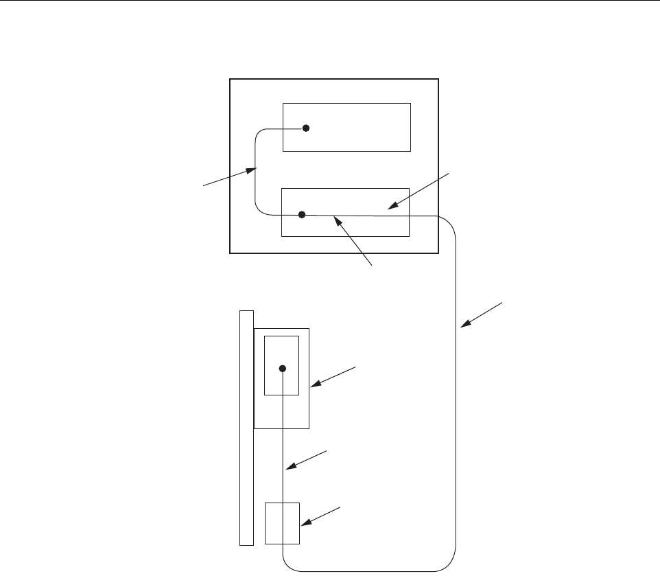
2 OUTDOOR CABINET OSP FIBER CABLE INSTALLATION GUIDELINES
The outside plant (OSP) fiber optic cables should be routed between the HU and RU outdoor
cabinet and terminated before the equipment is installed. Adiagram of atypical OSP cable
routing is shown in Figure 3-1.At the HU, the OSP cable should be terminated at afiber
distribution panel and spliced to pigtails. Jumper patch cords may then be used to link the HU
optical ports to the OSP cable terminations. Whenever possible, aguideway such as the
FiberGuide system should be provided to protect the fiber optic patch cords from damage and to
prevent excessive bending. The procedures for connecting the OSP cable optical fibers to the
HU is provided in Section 7.
ADCP-75-150 • Preliminary Issue A • March 2003 • Section 3: Host Unit Installation
Page 3-3
©2003, ADC Telecommunications, Inc.
Figure 3-1. Typical OSP Cable Routing
At the RU outdoor cabinet, the OSP fiber optic cable should be spliced to aconnectorized
outdoor-rated cable (consisting of individual jacketed pigtails) which is routed into the cabinet.
The individual pigtails can then be connected directly to the STM optical ports. Aconnector is
provided on the bottom of the RU outdoor cabinet to seal the cable entry point and provide
strain relief. The procedure for routing the fiber cable into the cabinet and for connecting the
pigtail leads to the STM is provided in the Digivance 20 Watt Outdoor Remote Unit Installation
Instructions (ADCP-75-148).
HOST UNIT
FIBER DISTRIBUTION PANEL
X
X
STM
REMOTE SITE
HOST SITE
PATCH
CORD
SPLICE
PIGTAIL
SPLICE
ENCLOSURE
INDOOR/OUTDOOR
CABLE WITH
PIGTAIL LEADS
OUTSIDE PLANT
CABLE
REMOTE UNIT
CABINET
16889-A
ADCP-75-150 • Preliminary Issue A • March 2003 • Section 3: Host Unit Installation
Page 3-4
©2003, ADC Telecommunications, Inc.
3 WDM MOUNTING PROCEDURE (OPTIONAL ACCESSORY)
Abi-directional wavelength division multiplexer (WDM) system is available as an accessory
item for the Digivance LRCS. If the application does not require the use of aWDM, skip this
section and proceed to Section 4.
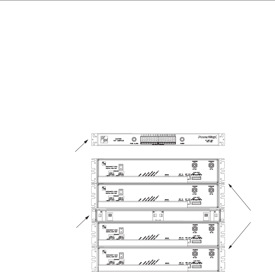
At the HU, the WDM system consists of aWDM module and aWDM mounting shelf. Each
WDM module can support two HU’s and each WDM mounting shelf can hold two WDM
modules. Afully loaded WDM mounting shelf can therefore support four HU’s.
When multiple HU’s require connection to aWDM, the WDM mounting shelf and the HU’s
should be mounted in the equipment rack as shown in Figure 3-2.This configuration allows the
pigtail leads from the two WDM modules to be connected directly to the optical ports on any
one of the four HU’s.
Figure 3-2. Typical WDM and HU Configuration
The WDM mounting shelf may be mounted in either a19-inch or 23-inch EIA or WECO
equipment rack. Four #12-24 screws are provided for securing the mounting shelf to the rack.
Use the following procedure to install the WDM mounting shelf in the equipment rack and to
mount the WDM modules in the WDM mounting shelf:
1. The WDM mounting shelf is shipped with the mounting brackets installed for 19-inch EIA
rack installations. If installing the mounting shelf in a19-inch EIA rack, proceed to step 5.
If installing the mounting shelf in a19-inch WECO rack, a23-inch EIA rack, or a23-inch
WECO rack, proceed to step 2.
WDM MOUNTING
SHELF
(WITHOUT MODULES)
18652-A
POWERWORX
FUSE PANEL
HOST UNITS
ADCP-75-150 • Preliminary Issue A • March 2003 • Section 3: Host Unit Installation
Page 3-5
©2003, ADC Telecommunications, Inc.
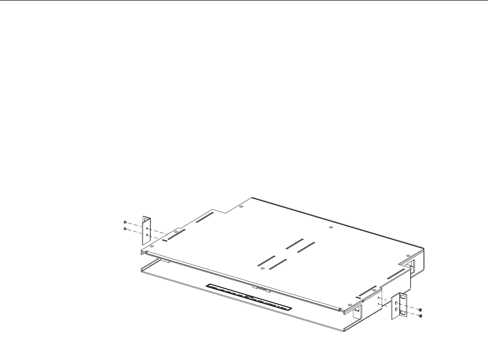
2. Remove both mounting brackets from the mounting shelf (requires Phillips screwdriver)
and save screws for reuse.
3. Locate the extra mounting brackets that are provided with the mounting shelf and select
the brackets that correspond to the rack type. Each mounting shelf includes extra brackets
for installing the mounting shelf in the rack types specified in step 1.
4. Install the replacement mounting brackets as shown in Figure 3-3.Use the screws
removed in step 2to attach the new brackets to the mounting shelf.
Figure 3-3. Installing the Replacement Mounting Brackets
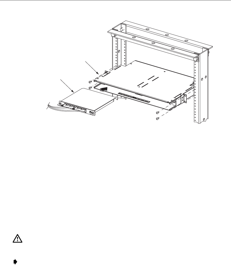
5. Position the WDM mounting shelf in the designated mounting space in the rack (per
system design plan) and then secure the mounting brackets to the rack using the four #12-
24 machine screws provided as shown in Figure 3-4.
6. Install each WDM module in the mounting shelf (see Figure 3-4). Arail on the side of the
module fits into aguide within the mounting.
7. Secure each WDM module to the mounting shelf by twisting the handle on each quarter-
turn fastener 90º.
8. Carefully store the pigtail leads from each WDM module. The routing and connection
procedures for the pigtails are provided in Section 7.
16885-A
ADCP-75-150 • Preliminary Issue A • March 2003 • Section 3: Host Unit Installation
Page 3-6
©2003, ADC Telecommunications, Inc.
Figure 3-4. WDM Mounting Shelf and WDM Module Installation
4 HU MOUNTING PROCEDURE
The HU may be mounted in either a19-inch or 23-inch EIA or WECO equipment rack. Both
US standard and metric machine screws are included for rack mounting the HU. When loading
the HU in arack, make sure the mechanical loading of the rack is even to avoid ahazardous
condition such as aseverely unbalanced rack. The rack should safety support the combined
weight of all the equipment it holds. In addition, maximum recommended ambient temperature
for the HU is 50º C(122º F). Allow sufficient air circulation or space between units when the
HU is installed in amulti-rack assembly because the operating ambient temperature of the rack
environment might be greater than room ambient.
Use the following procedure to install the HU in the equipment rack:
1. The HU is shipped with the mounting brackets installed for 19-inch rack installations. If
mounting the HU in a19-inch rack, proceed to step 4. If mounting the HU in a23-inch
rack, proceed to step 2.
2. Remove both mounting brackets from the HU (requires TORX screwdriver with T20 bit)
and save screws for reuse.
Warning: Wet conditions increase the potential for receiving an electrical shock when
installing or using electrically powered equipment. To prevent electrical shock, never install or
use electrical equipment in awet location or during alightning storm.
Note: To insure that all optical connectors remain dust-free during installation, leave all dust
caps and dust protectors in place until directed to remove them for connection.
16888-A
WDM MODULE
WDM MOUNTING
SHELF
ADCP-75-150 • Preliminary Issue A • March 2003 • Section 3: Host Unit Installation
Page 3-7
©2003, ADC Telecommunications, Inc.
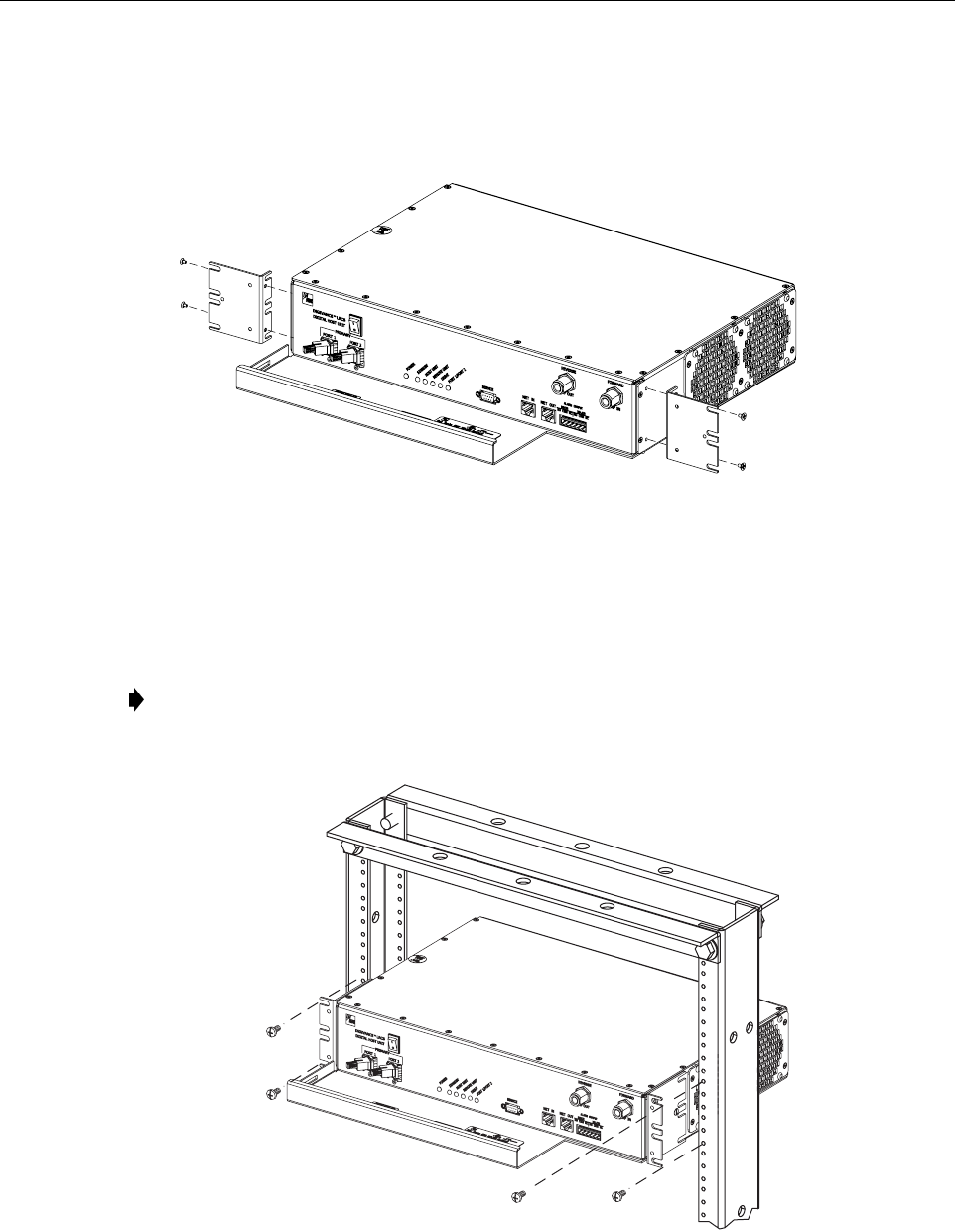
3. Reinstall both mounting brackets so the long side of the bracket is flush with the HU front
panel as shown in Figure 3-5.Use the screws removed in step 2to re-attach the brackets to
the HU chassis.
Figure 3-5. Installing the Mounting Brackets for 23-Inch Rack Installations
4. Position the HU in the designated mounting space in the rack (per system design plan) and
then secure the mounting brackets to the rack using the four machine screws provided (use
#12-24 or M6 x10 screws, whichever is appropriate) as shown in Figure 3-6.
Figure 3-6. HU Rack Mount Installation
Note: Provide aminimum of 3inches (76 mm) of clearance space on both the left and
right sides of the HU for air intake and exhaust.
18653-A
REMOVE AND REINSTALL MOUNTING
BRACKETS AS SHOWN FOR
INSTALLATION IN 23-INCH RACKS
18654-A
ADCP-75-150 • Preliminary Issue A • March 2003 • Section 3: Host Unit Installation
Page 3-8
©2003, ADC Telecommunications, Inc.
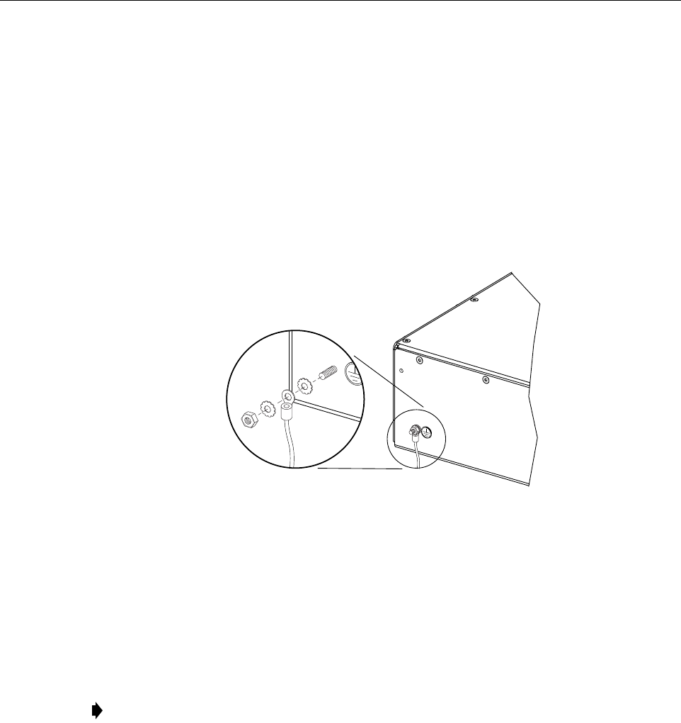
5 CHASSIS GROUND CONNECTION
Astud is provided on the rear side of the chassis for connecting agrounding wire to the chassis.
Use the following procedure to connect the grounding wire to the chassis and to route the
grounding wire to an approved earth ground source.
1. Obtain alength of #18 AWG (1.00 mm) insulated stranded copper wire for use as a
chassis grounding wire.
2. Terminate one end of the wire with aring terminal.
3. Locate the chassis ground stud at the rear of the HU as shown in Figure 3-7.
Figure 3-7. Chassis Ground Stud
4. Attach the ring end of the wire to the chassis ground stud (see Figure 3-7).
5. Route the free end of the chassis grounding wire to an approved (per local code or
practice) earth ground source.
6. Cut the chassis grounding wire to length and connect it to the approved ground source as
required by local code or practice.
6 COAXIAL CABLE CONNECTIONS
The RF interface between the HU and the BTS is supported through two type Nfemale
connectors mounted on the HU front panel. One connector provides the coaxial cable
connection for the forward path (downlink) signal and the other connector provides the coaxial
cable connection for the reverse path (uplink) signal.
In most installations, it is usually necessary to insert some attenuation in the forward path link
between the HU and the BTS. Asignal level that is greater than –10 dBm will overdrive and
Note: Be sure to maintain reliable grounding. Pay particular attention to ground source
connections.
16169-A
ADCP-75-150 • Preliminary Issue A • March 2003 • Section 3: Host Unit Installation
Page 3-9
©2003, ADC Telecommunications, Inc.
possibly damage the HU receiver. Refer to Section 4, Subsection 2.3, before completing the
forward path connection between the BTU and HU. If the Conditioning Panel or Duplexing
Panel is required, refer to the Digivance 800 and 1900 MHz Interface Panels User Manual
(ADCP-75-147) for the installation procedures. The HU should be mounted as close as possible
to the BTS to minimize cable losses. Use the following procedure to route and connect the
forward and reverse path coaxial cables to the HU:
1. Obtain the required lengths of high performance, flexible, low loss 50-ohm coaxial
communications cable (RG-400 or equivalent) for all coaxial connections.
2. Route the forward and reverse path coaxial cables between the HU and the BTS interface
(per system design plan) and cut to the required length. Allow sufficient slack for dressing
and organizing cables at the HU and for installing an external attenuator in the forward
path link.
3. Terminate each cable with atype Nmale connector following the connector supplier’s
recommendations.
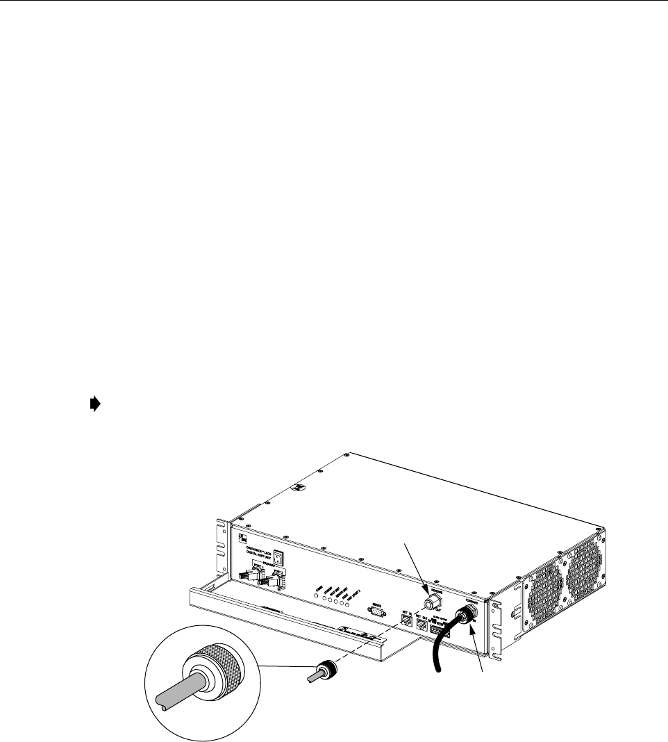
4. Connect the forward path cable to the FORWARD RF IN connector on the HU front
panel as shown in Figure 3-8.
Figure 3-8. Forward and Reverse Path Coaxial Cable Connections
5. Connect the reverse path cable to the REVERSE RF OUT connector on the HU front
panel (see Figure 3-8).
6. Dress and secure cables at the HU.
7. Complete all remaining coaxial connections as specified in the system design plan.
Note: Do not connect the forward path cable at the BTS until the composite forward path
RF signal level is measured and the amount of attenuation required is determined.
18655-A
TYPE-N MALE
CONNECTOR
FORWARD RF IN
CONNECTOR
(FORWARD PATH)
REVERSE
RF OUT CONNECTOR
(REVERSE PATH)

ADCP-75-150 • Preliminary Issue A • March 2003 • Section 3: Host Unit Installation
Page 3-10
©2003, ADC Telecommunications, Inc.
7 OPTICAL CONNECTIONS
The optical interface between the HU and the RU is supported by two optical ports. Each optical
port consists of an SC optical adapter which is mounted on the HU front panel. Port 1provides
the optical fiber connection for the forward path (downlink) signal. Port 2provides the optical
fiber connection for the reverse path (uplink) signal.
The optical connections are dependent on whether or not aWDM (accessory) or CWDM
(accessory) module is installed. If the installation does not include aWDM, proceed to Section
7.1 for the optical connections procedure. If the installation includes aWDM, proceed to
Section 7.2 for the optical connections procedure. If the installation includes aCWDM, refer to
the Digivance System Coarse Wavelength Division Multiplexer User Manual (ADCP-75-142)
for the optical connection procedure.
7.1 Optical Connections Without WDM
Use the following procedure to connect the optical fibers when aWDM is not installed with the HU:
1. Obtain two patch cords that are of sufficient length to reach from the HU to the fiber
distribution panel.
2. Designate one of the patch cords as the forward path link and the other as the reverse
path link and attach an identification label or tag next to the connector.
3. Remove the dust caps from the HU optical ports and from the patch cord connectors that
will be connected to the HU.
4. Clean each patch cord connector (follow connector supplier’s recommendations).
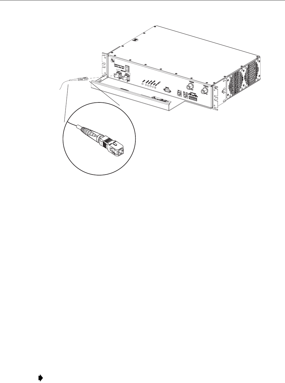
5. Insert the connector into the appropriate optical port as shown in Figure 3-9 and as
specified by the following:
Port 1 - Forward path patch cord
Port 2 - Reverse path patch cord
6. Route the patch cords from the HU to the fiber distribution panel.
Danger: This equipment uses aClass 1Laser according to FDA/CDRH rules. Laser radiation
can seriously damage the retina of the eye. Do not look into the ends of any optical fiber. Do not
look directly into the optical transmitter of any unit or exposure to laser radiation may result.
An optical power meter should be used to verify active fibers. Aprotective cap or hood MUST
be immediately placed over any radiating transmitter or optical fiber connector to avoid the
potential of dangerous amounts of radiation exposure. This practice also prevents dirt particles
from entering the connector.
Note: To protect the optical receivers, insert a15 dB attenuator in each optical path. After
the optical power has been measured, the attenuator may be resized or removed.
Note: The HU optical adapters are angled to the left.Therefore, patch cords should always
be routed to the HU from the left side of the rack. Routing patch cords to the HU from the
right side of the rack may exceed the bend radius limitations for the optical fiber.
ADCP-75-150 • Preliminary Issue A • March 2003 • Section 3: Host Unit Installation
Page 3-11
©2003, ADC Telecommunications, Inc.
Figure 3-9. Fiber Optic Cable Connections To Host Unit
7. Identify the OSP cable optical fiber terminations that correspond to the RU.
8. Designate one of the OSP fibers as the forward path link and the other as the reverse
path link and attach an identification label or tag next to the connector.
9. Remove the dust caps from the OSP cable optical fiber adapters and from the patch cord
connectors.
10. Clean each patch cord connector (follow connector supplier’s recommendations) and then
mate the connector with the appropriate OSP cable adapter.
11. Store any excess patch cord slack at the fiber distribution panel.
7.2 Optical Connections With WDM
Use the following procedure to connect the optical fibers when aWDM module is installed with
the HU:
1. Obtain apatch cord that is of sufficient length to reach from the WDM module to the fiber
distribution panel.
2. Remove the dust cap from one of the two optical ports on the WDM module and from the
patch cord connector that will be connected to the WDM module.
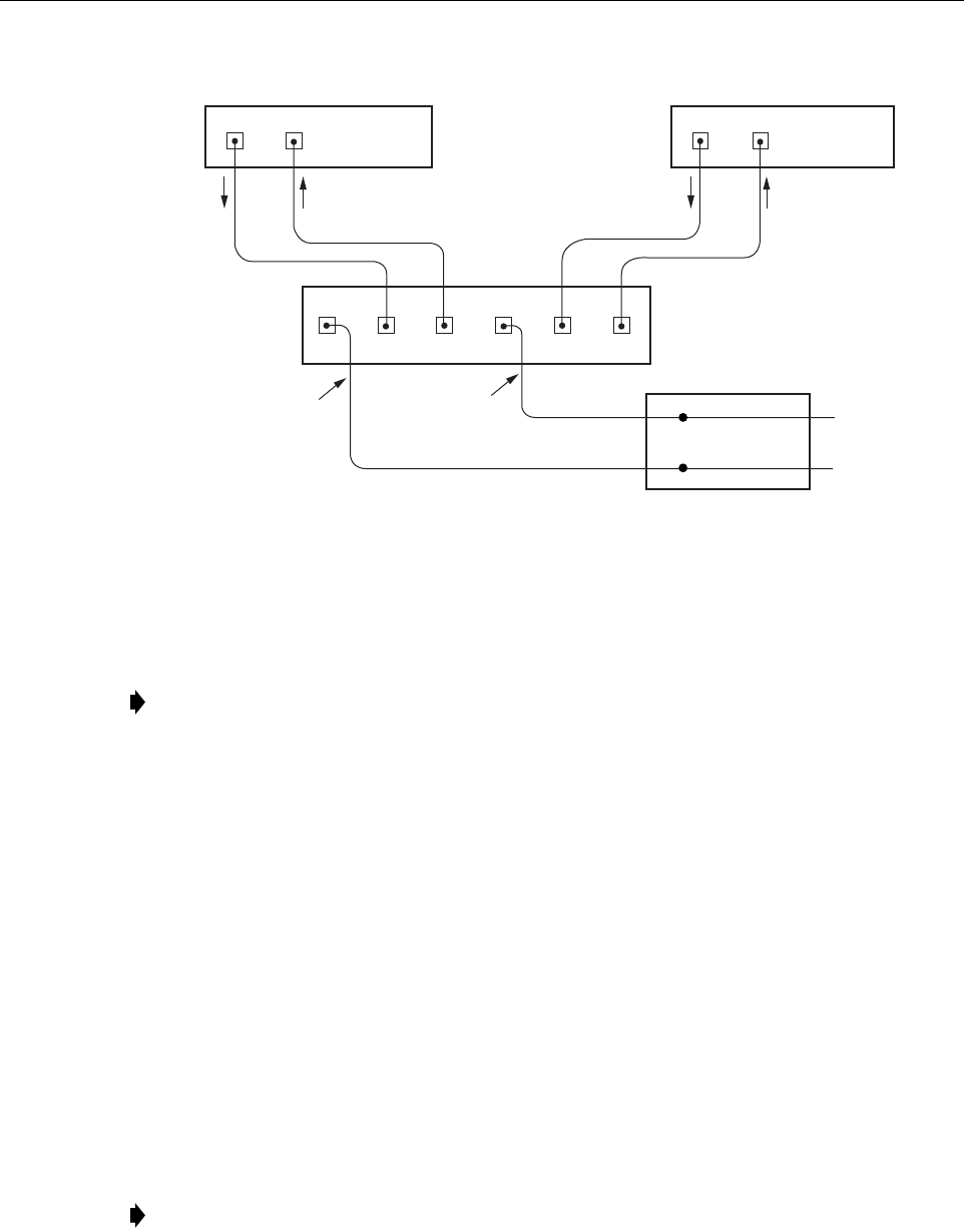
Note: Each WDM module can support two separate HU’s. The WDM module ports are
numbered from 1through 6as shown in Figure 3-10.Ports 1through 3are used for HU #1
and Ports 4through 6are used for HU #2.
18656-A
ADCP-75-150 • Preliminary Issue A • March 2003 • Section 3: Host Unit Installation
Page 3-12
©2003, ADC Telecommunications, Inc.
Figure 3-10. Fiber Optic Connections To WDM Module
3. Clean the patch cord connector (follow connector supplier’s recommendations).
4. Insert the connector into one of the WDM module’s optical ports (port 1or 4).
5. Route the patch cord from the WDM to the fiber distribution panel.
6. Identify the OSP cable optical fiber termination that corresponds to the RU.
7. Remove the dust cap from the OSP cable optical adapter and from the patch cord
connector.
8. Clean the patch cord connector (follow connector supplier’s recommendations) and then
mate the connector with the appropriate OSP cable adapter.
9. Store any excess patch cord slack at the fiber distribution panel.
10. Remove the dust caps from the HU optical ports and from the WDM pigtails that will be
connected to the HU.
11. Clean each pigtail connector (follow connector supplier’s recommendations) and then
insert the connector into the appropriate optical port on the HU as shown in Figure 3-9 and
as diagramed in Figure 3-10.
Note: To protect the optical receivers, insert a15 dB attenuator in each optical path. After
the optical power has been measured, the attenuator may be resized or removed.
Note: The HU optical adapters are angled to the left.Therefore, pigtails should always be
routed to the HU from the left side of the rack. Routing pigtails to the HU from the right
side of the rack may exceed the bend radius limitations for the optical fiber.
PORT 1 PORT 2
HOST UNIT 1 HOST UNIT 2
PORT 1 PORT 2
18657-A
REVERSE
PATH
REVERSE
PATH
FORWARD
PATH
FORWARD
PATH
WAVELENGTH DIVISION
MULTIPLEXER
OSP CABLE
OPTICAL FIBERS
HOST UNIT 1
(BI-DIRECTIONAL FIBER
LINK WITH REMOTE UNIT)
HOST UNIT 2
(BI-DIRECTIONAL FIBER
LINK WITH REMOTE UNIT)
FIBER DISTRIBUTION
PANEL (FDP)
X
X
123 45 6
ADCP-75-150 • Preliminary Issue A • March 2003 • Section 3: Host Unit Installation
Page 3-13
©2003, ADC Telecommunications, Inc.
8 CONTROLLER AREA NETWORK CONNECTIONS
Controller area Network (CAN) interface connections between multiple HU’s are supported by
apair of RJ-45 jacks. One of the jacks is designated as the NET IN port and the other jack is
designated as the NET OUT port. The CAN interface allows up to 24 HU’s to be connected
together (in daisy-chain fashion) and controlled through asingle Digivance EMS computer. A
one meter long cable is provided with each HU for CAN connections. Use the following
procedure to connect CAN interface cables between multiple HU’s:
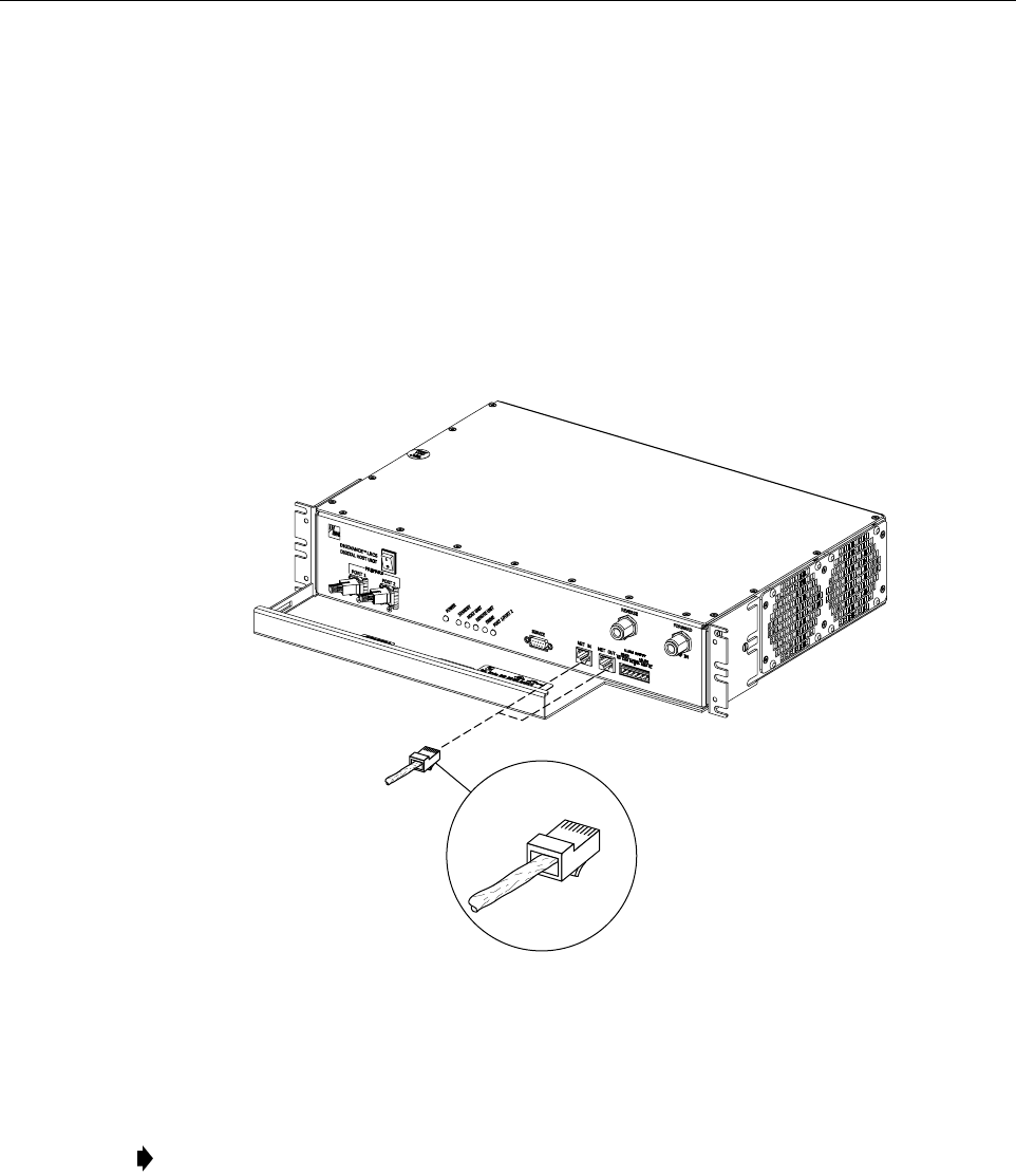
1. Connect one end of the CAN interface cable (provided with the HU) to either the NET IN
or NET OUT port on HU #1 as shown in Figure 3-11.
Figure 3-11. Controller Area Network Connections
2. Route the CAN interface cable to HU #2 and connect the cable’s free end to the port that is
the logical opposite of the network port the cable was connected to at HU #1.
3. If athird HU will be connected to the network, connect asecond CAN interface cable to
the remaining network port on HU #2.
4. Route the second CAN interface cable to HU #3 and connect the cable’s free end to the
port that is the logical opposite of the port that the cable is connected to at HU #2.
5. Repeat steps 3and 4for each additional HU that is added to the network up to atotal of 24
HU’s. Adiagram of typical CAN interface connections is shown in Figure 3-12.
Note: If connected to aNET OUT port at HU #1, connect to the NET IN port at HU #2. If
connected to aNET IN port at HU #1, connect to aNet OUT port at HU #2.
18658-A
RJ-45 CONNECTOR
DETAIL