ADC Telecommunications DLC0802A Digivance 800 MHz 20 Watts System User Manual 75150
ADC Telecommunications Inc Digivance 800 MHz 20 Watts System 75150
Contents
manual2

ADCP-75-150 • Preliminary Issue A • March 2003 • Section 2: Description
Page 2-15
©2003, ADC Telecommunications, Inc.
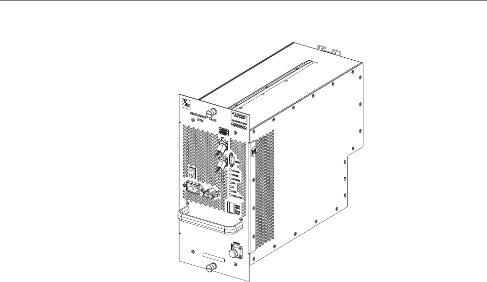
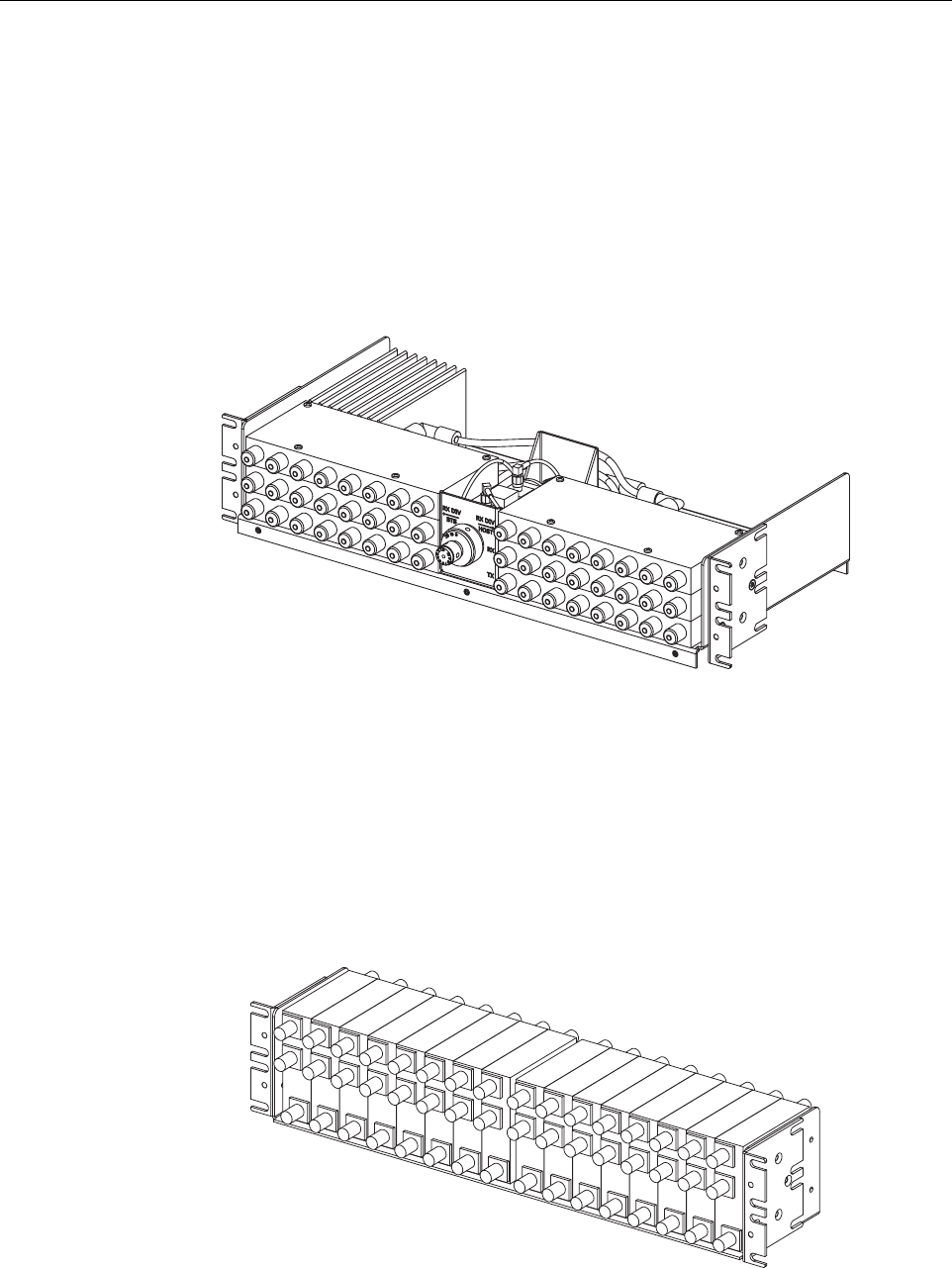
5 SPECTRUM TRANSPORT MODULE
The Spectrum Transport Module (STM), shown in Figure 2-7,provides the following basic
functions:
• Provides an RF interface (antenna ports) to the remote antenna(s).
• Provides an optical interface to the HU.
•Convertsthe digitized forward path optical signal to adigitized RF signal.
•Convertsthe digitized RF signal to acomposite RF signal.
• Digitizes the reverse path composite RF signal.
•Convertsthe digitized reverse path RF signal to adigitized optical signal.
• Provides an RS-232 interface for connecting alocal DEMS computer.
• Transports alarm, control, and monitoring information via the optical link.
• Provides AC power input.
• Provides external alarm input.
5.1 Primary Components
The STM consists of an electronic circuit board assembly, power supply, duplexer, and fan
assembly that are mounted within apowder-paint coated sheet metal enclosure. The metal
enclosure provides amounting point for the electronic components and controls RF emissions.
Except for the fan unit, the electronic components are not user replaceable. The STM is
designed for use within the RU outdoor cabinet or indoor mounting shelf. Except for the LPA
interface connector, all controls, connectors, indicators, and switches are mounted on the STM
front panel for easy access. Acarrying handle is provided on the front of the STM to facilitate
installation and transport.
Table 2-3. Remote Unit Outdoor Mounting Shelf User Interface
REF
NO DEVICE FUNCTIONAL DESCRIPTION
1STMmounting slot Provides amounting point for the STM module.
2LPAmounting slot Provides amounting point for the LPA module.
3 Grounding lug Provides aconnection point for an external grounding cable.
4ACpower cable Provides AC power to the STM.
5WDMmounting slot Provides amounting point for the WDM module.
6CWDMmounting slot Provides amounting point for the CWDM module.
7CWDMpower cord Provides DC power to the CWDM module.
FCC ID: F8I-DLC0802A User Manual - Part 2
ADCP-75-150 • Preliminary Issue A • March 2003 • Section 2: Description
Page 2-16
©2003, ADC Telecommunications, Inc.
Figure 2-7. Spectrum Transport Module
5.2 Mounting
The STM mounts within the RU outdoor cabinet or indoor mounting shelf. Arunner on the
bottom of the STM meshes with atrack inside the cabinet/mounting shelf. The runner and track
guide the STM into the installed position. The electrical interface between the STM and LPA is
supported by aD-sub female connector located on the rear side of the STM. Acorresponding D-
sub male connector mounted at the rear of the RU cabinet/mounting shelf mates with the STM
connector. Captive screws are provided for securing the STM in the installed position.
5.3 Fault Detection and Alarm Reporting
The STM detects and reports various faults including remote unit fault, optical fault, power
fault, temperature fault, power amplifier fault, and external (door open) fault. Various front
panel Light Emitting Diode (LED) indicators turn from green to red or yellow if afault is
detected. The status of the STM, the alarm state (major or minor), and other alarm information
is summarized and reported over the optical fiber to the HU and also over the service interface.
In addition, the alarm state of the HU is received over the optical fiber and reported to the service
interface. This information may be accessed remotely through the NOC/NEM interface or
locally through the DEMS software GUI.
5.4 Antenna Cable Connection
The antenna cable connections between the STM and the antenna are supported through one N-
type female connector which carries both the forward and reverse path RF signals. When
installed in the RU outdoor cabinet, the STM does not connect directly to the antenna but
18634-A

ADCP-75-150 • Preliminary Issue A • March 2003 • Section 2: Description
Page 2-17
©2003, ADC Telecommunications, Inc.
instead connects to alightning protector that is mounted on the bottom of the cabinet (see
Section 3.6). Acoaxial jumper cable is provided (included with the enclosure) for connecting
the STM connector to the lightning protector.
5.5 RF Signal Level Adjustment
The STM is equipped with adigital attenuator for adjusting the signal level of the forward path
RF output signal. The remote forward path attenuator adjusts the level of the output RF signal
at the RU antenna port and will add from 0to 31 dB of attenuation to the output signal level.
The attenuator can be set in 1dB increments. The attenuator is software controlled and is
adjusted through the NOC/NEM interface or the DEMS software GUI.
5.6 Optical Connection
Fiber optic connections between the STM and the HU are supported through two SC-type
optical connector ports. One port is used for connecting the forward path optical signal and the
other port is used for connecting the primary reverse path optical signal.
5.7 Service Interface Connection
The service interface connection between the STM and alocal laptop computer loaded with the
DEMS software is supported by asingle DB-9 female connector. The service interface
connector provides an RS-232 DTE interface. The STM service interface connector supports
local communications with both the STM and the corresponding HU.
5.8 Powering
The STM is powered by 120 or 240 Vac (50 or 60 Hz) power which is supplied through athree-
conductor AC power cord. The power cord is provided with the RU outdoor cabinet or indoor
mounting shelf. The power cord connects to an AC connector mounted on the STM front panel.
Aswitch on the STM front panel provides AC power On/Off control.
5.9 Cooling
Continuous air-flow for cooling is provided by asingle fan mounted on the rear side of the STM
housing. An alarm is provided that indicates if ahigh temperature condition (>50º C/122º F)
occurs. If the temperature falls below 32º F(0º C), the fan automatically shuts off. The fan may
be field replaced if it fails.
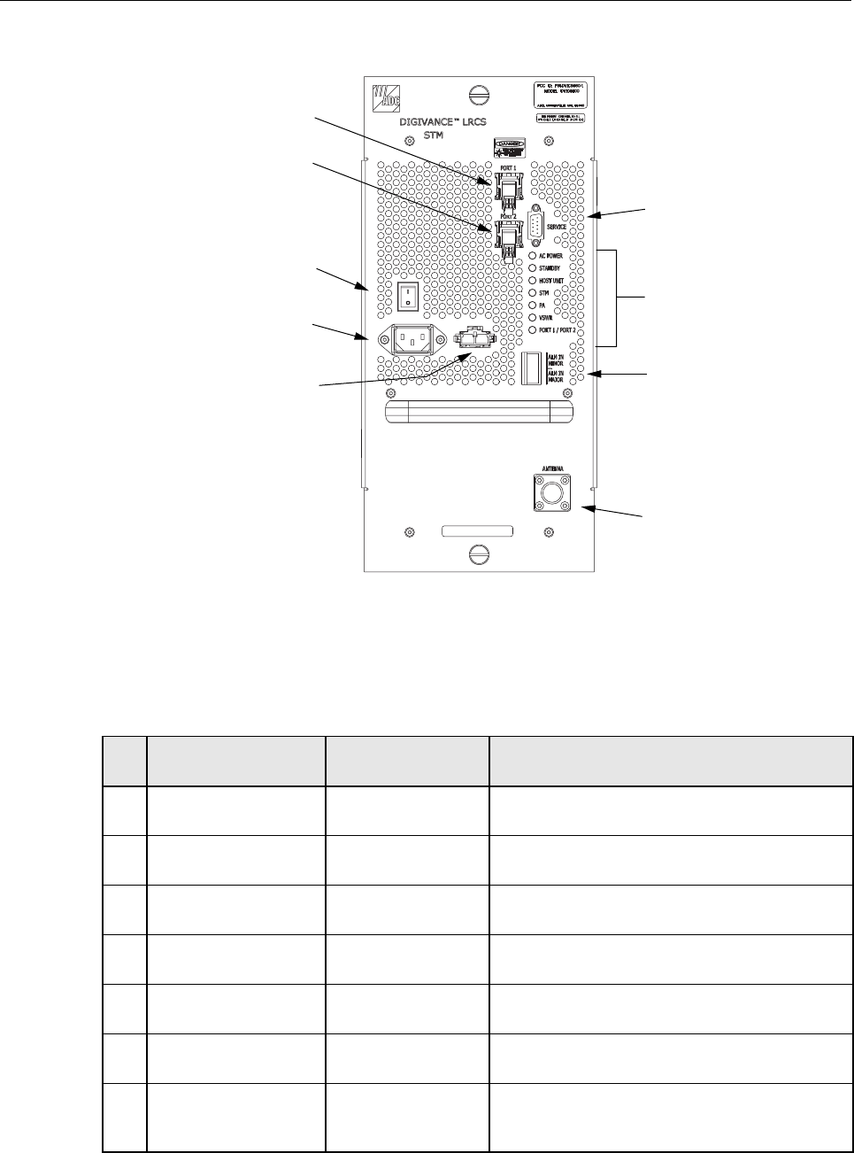
5.10 User Interface
The STM user interface consists of the various connectors, switches, and LEDs that are
provided on the STM front panel. The STM user interface points are indicated in Figure 2-8 and
described in Table 2-4.
ADCP-75-150 • Preliminary Issue A • March 2003 • Section 2: Description
Page 2-18
©2003, ADC Telecommunications, Inc.
Figure 2-8. Spectrum Transport Module User Interface
Table 2-4. Spectrum Transport Module User Interface
REF
NO
USER INTERFACE
DESIGNATION DEVICE FUNCTIONAL
DESCRIPTION
1PORT1SCconnector
(single-mode) Input connection point for the forward path opti-
cal fiber.
2PORT2SCconnector
(single-mode) Output connection point for the reverse path pri-
mary optical fiber.
3I/0 On/Off rocker
switch Provides AC power on/off control.
4Nodesignation 3-wire AC power
cord connector Connection point for the AC power cord.
5Nodesignation 2- wire DC power
cord connector Connection point for aback-up battery power
cord. (Not used with 20 Watt system)
6 SERVICE DB-9 connector
(female) Connection point for the RS-232 service inter-
face cable.
7ACPOWER Multi-colored LED
(green/red)
Indicates if the STM is powered by the AC power
source (green) or the back-up battery system
(red). See Note.
18636-A
(3) ON/OFF
SWITCH
(4) AC POWER
CONNECTOR
(5) DC POWER
CONNECTOR
(1) PORT 1
CONNECTOR
(2) PORT 2
CONNECTOR
(6) SERVICE
CONNECTOR
(7-13) LED
INDICATORS
(14) ALARM
CONNECTOR
(15) ANTENNA
CONNECTOR

ADCP-75-150 • Preliminary Issue A • March 2003 • Section 2: Description
Page 2-19
©2003, ADC Telecommunications, Inc.
6 LINEAR POWER AMPLIFIER
The Linear Power Amplifier (LPA), shown in Figure 2-9,works is conjunction with the STM to
amplify the forward path RF output signal. The STM is interfaced with the LPA through the D-
sub connectors and wiring harness located at the rear of the RU cabinet/mounting shelf. The RF
signal is passed to the LPA for amplification and then passed back to the STM for filtering and
output via the STM’s ANTENNA port. The STM also supplies DC power to the LPA through
the same interface.
6.1 Primary Components
The LPA consists of several electronic circuit board assemblies and one fan that are mounted
within apowder-paint coated sheet metal enclosure. The metal enclosure provides amounting
point for the electronic components and controls RF emissions. Except for the fan unit, the
electronic components are not user replaceable. The LPA is designed for use within the RU
outdoor cabinet or indoor mounting shelf. Except for the STM interface connector, all controls,
indicators, and switches are mounted on the LPA front panel for easy access. Acarrying handle
is provided on the front of the LPA to facilitate installation and transport.
8 STANDBY Multi-colored LED
(green/yellow/red)
Indicates if the system is in the Normal state (off)
Standby state (blinking green), Test state (blink-
ing red), or Program Load state (blinking yel-
low). See Note.
9 HOST UNIT Multi-colored LED
(green/yellow/red)
Indicates if no alarm (green), aminor alarm (yel-
low), or amajor alarm (red) is reported by the
HU. See Note.
10 STM Multi-colored LED
(green/yellow/red)
Indicates if the STM is normal (green) or faulty
(red). See Note.
11 PA Multi-colored LED
(green/yellow/red)
Indicates if the power amplifier is normal
(green), over temperature (yellow), has afan fail-
ure (yellow), or is faulty (red). See Note.
12 VSWR Multi-colored LED
(green/yellow/red)
Indicates if the forward path VSWR is above
(red) or below (green) the fault threshold.
13 PORT 1/PORT 2 Multi-colored LED
(green/yellow/red)
Indicates if the forward path optical signal
received from the HU is normal (green) or if
errors are detected (red). See Note.
14 ALARM IN MINOR
ALARM IN MAJOR
Screw-type terminal
connector (14–26
AWG)
Connection point for two external alarm inputs.
The door-open switch lead wires are typically
connected to the major alarm terminals.
15 ANTENNA N-type female RF
coaxial connector Connection point for the antenna.
Note: Amore detailed description of LED operation is provided in Section 5.
Table 2-4. Spectrum Transport Module User Interface, continued
REF
NO
USER INTERFACE
DESIGNATION DEVICE FUNCTIONAL
DESCRIPTION
ADCP-75-150 • Preliminary Issue A • March 2003 • Section 2: Description
Page 2-20
©2003, ADC Telecommunications, Inc.
Figure 2-9. Linear Power Amplifier
6.2 Mounting
The LPA mounts within the RU outdoor cabinet or indoor mounting shelf. Runners on the top
and bottom of the LPA mesh with tracks. The runners and tracks guide the LPA into the
installed position. The electrical interface between the STM and LPA is supported by aD-sub
female connector located on the rear side of the LPA. Acorresponding D-sub male connector
mounted at the rear of the RU cabinet/mounting shelf mates with the LPA connector. Captive
screws are provided for securing the LPA in the installed position.
6.3 Fault Detection and Alarm Reporting
The LPA in conjunction with the STM detects and reports various faults including power
amplifier fault, output power fault, temperature fault, and fan fault. Asingle Light Emitting
Diode (LED) indicator, located on the front panel of the LPA, turns from green to red or yellow
if an LPA fault is detected. The status of the LPA, the alarm state (major or minor), and other
information is summarized and reported (by the STM) over the optical fiber to the HU and also
to the service interface. This information may be accessed remotely through the NOC/NEM
interface or locally through the DEMS software GUI.
6.4 Powering
The LPA is powered by various DC voltages which are supplied by the STM over the electrical
interface provided by the D-sub connectors and wiring harness mounted within the RU cabinet/
mounting shelf.
18640-A
STATUS
MUTE
NORM
RESET
ADCP-75-150 • Preliminary Issue A • March 2003 • Section 2: Description
Page 2-21
©2003, ADC Telecommunications, Inc.
6.5 Cooling
Continuous air-flow for cooling is provided by afan mounted at the front of the LPA housing.
Cool air is pulled into the module from the front and heated air is exhausted out the back. An
alarm is provided that indicates if ahigh temperature condition (>50º C/122º F) occurs or if a
fan failure occurs. The fan may be field replaced if it fails.
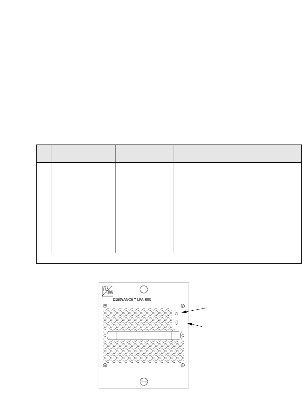
6.6 User Interface
The LPA user interface consists of an LED indicator and aswitch that are mounted on the LPA
front panel. The LPA user interface points are described in Table 2-5 and indicated in
Figure 2-10.
Figure 2-10. Linear Power Amplifier User Interface
Table 2-5. Linear Power Amplifier User Interface
REF
NO
USER INTERFACE
DESIGNATION DEVICE FUNCTIONAL
DESCRIPTION
1 STATUS LED indicator
(green, yellow, and
red)
Indicates the operational state of the LPA and
whether or not there are any faults.
2MUTE
NORM
RESET
3-position switch
with one momentary
contact position
Placing the switch in the MUTE position puts the
LPA in the shutdown state with RF output dis-
abled. With the switch in MUTE, the STM can not
control the LPA output power. Placing the switch
in the NORM position puts the LPA in the normal
state and allows the STM to enable and disable the
RF output. Momentarily placing the switch in the
RESET position clears all alarms and restarts the
LPA.
Note: Amore detailed description of the STATUS LED is provided in Section 5.
18639-A
STATUS
MUTE
NORM
RESET
(1) STATUS
(2) MUTE/NORM
/
RESET SWITCH
ADCP-75-150 • Preliminary Issue A • March 2003 • Section 2: Description
Page 2-22
©2003, ADC Telecommunications, Inc.
7 INTERFACE PANELS (ACCESSORY)
The interface panels are accessory items that are used when multiple BTS’s and multiple HU’s
require connection or when RF attenuation is needed between the BTS and HU. Two types of
panels are available: the Conditioning Panel and the Duplexing Panel. The Conditioning Panel,
shown in Figure 2-11,provides attenuation of the forward path signal to the level required for
input to the HU. The Conditioning Panel also provides forward and reverse path combining and
splitting (as needed) to enable multi-BTS to single HU, multi-BTS to multi-HU, or single BTS
to multi-HU configurations.
Figure 2-11. Conditioning Panel
The Duplexing Panel, shown in Figure 2-12,is used in conjunction with the Conditioning Panel
when the BTS provides aduplexed forward and reverse path RF connection. The Duplexing
Panel separates the duplexed forward and reverse path signals. This allows the BTS to be
connected to the HU which has separate forward and reverse path RF ports. For complete
information about the Conditioning Panel and Duplexing Panel, refer to the Digivance RF
Transport Solution 800 and 1900 MHz Interface Panels User Manual (ADCP-75-144).
Figure 2-12. Duplexing Panel
18644-A
18645-A
ADCP-75-150 • Preliminary Issue A • March 2003 • Section 2: Description
Page 2-23
©2003, ADC Telecommunications, Inc.
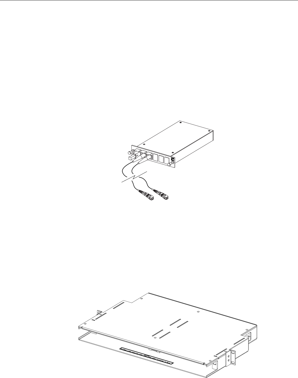
8 WAVELENGTH DIVISION MULTIPLEXER (ACCESSORY)
The Wavelength Division Multiplexer (WDM) module, shown in Figure 2-13,is an accessory
item that is used in applications when it is desireable or necessary to combine the forward and
reverse path optical signals from one Digivance system onto asingle optical fiber. Each WDM
consists of abi-directional wavelength division multiplexer mounted within apower-paint
coated sheetmetal enclosure. Asingle SC-type optical connector port is provided for connecting
the forward/reverse path optical fiber to the WDM module. Apair of pigtail leads with SC-type
connectors are provided for connecting the WDM module to the forward and reverse path
optical ports on the HU or STM.
Figure 2-13. Wavelength Division Multiplexer Module
In WDM applications, aWDM module must be installed at both the HU and the RU locations.
Amounting shelf, shown in Figure 2-14,is available for mounting WDM modules in the same
equipment rack as the HU. Each WDM module mounting shelf can support two WDM
modules. Both the RU outdoor cabinet and indoor mounting shelf provide amounting slot for
installing aWDM module.
Figure 2-14. WDM Module Mounting Shelf
17013-A
18646-A
ADCP-75-150 • Preliminary Issue A • March 2003 • Section 2: Description
Page 2-24
©2003, ADC Telecommunications, Inc.
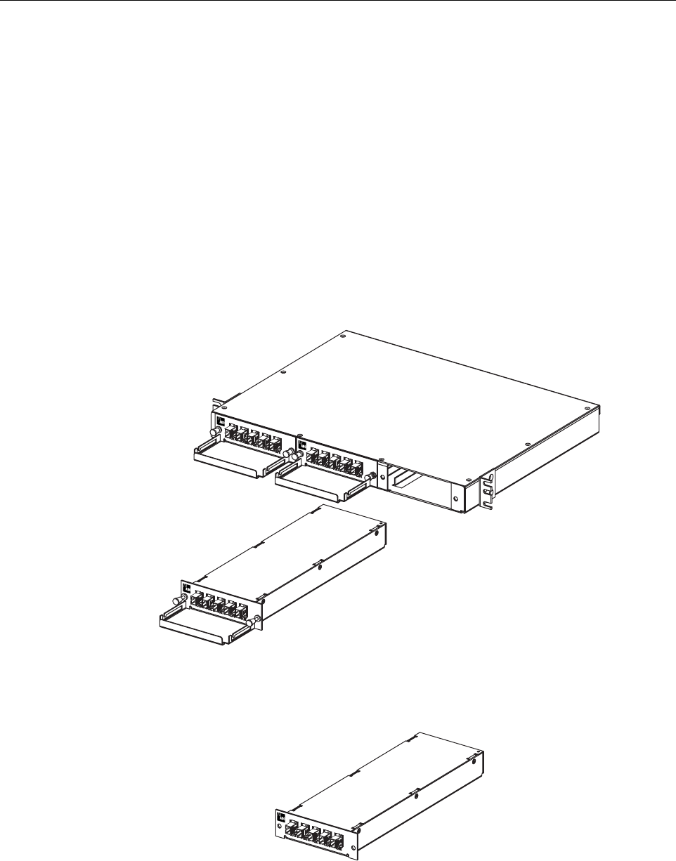
9 COARSE WAVELENGTH DIVISION MULTIPLER SYSTEM (ACCESSORY)
The Coarse Wavelength Division Multiplexer (CWDM) system is an accessory that is used
when it is desireable or necessary to combine the forward and reverve path optical signals from
up to four Digivance systems onto asingle optical fiber. Each CWDM system consists of a
CWDM Host module, CWDM Host module mounting shelf, and CWDM Remote module. The
CWDM Host module mounting shelf can support up to three CWDM Host modules. Both the
RU outdoor cabinet and indoor mounting shelf provide amounting slot for installing aCWDM
Remote module.
The CWDM Host Module and Host Module Mounting Shelf are shown in Figure 2-15.The
CWDM Remote Module is shown in Figure 2-16.For complete information about the CWDM
system, refer to the Digivance System Coarse Wavelength Division Multipler User Manual
(ADCP-75-142).
Figure 2-15. CWDM Host Module and Host Module Mounting Shelf
Figure 2-16. CWDM Remote Module
18647-A
18648-A
ADCP-75-150 • Preliminary Issue A • March 2003 • Section 2: Description
Page 2-25
©2003, ADC Telecommunications, Inc.
10 DIGIVANCE ELEMENT MANAGEMENT SYSTEM
The Digivance Element Management System (DEMS) is anetwork management tool that
provides control and monitoring functions for the Digivance system. The DEMS is used to
provision and configure new systems for operation, set system operating parameters, get system
alarm and status messages, and upgrade the system software. The DEMS supports both local
control by an on-site service technician and remote control by aNetwork Operations Center
(NOC).
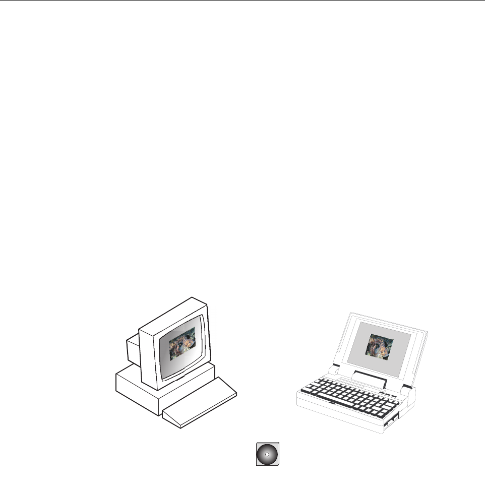
10.1 Primary Components
The DEMS, shown in Figure 2-17,consists of aPC-type desk-top computer (not provided) that
is loaded with the DEMS software. The DEMS software is stored on aCD-ROM that is shipped
with the HU. The DEMS software must be installed on the DEMS computer along with the Java
2Version 1.3.1 Runtime Environment software which is also provided. Installation consists of
inserting the CD-ROM into the computer’s CD-ROM drive and then running the software install
programs. This places the Java 2Runtime Environment and DEMS software files in assigned
folders on the computer’s hard drive.
Figure 2-17. Alarm Network Unit
The DEMS software may also be installed on aPC-type lap-top computer (not provided). Alap-
top version of the DEMS computer can be used as aportable network management tool for
service and maintenance purposes. Alaptop DEMS computer can be connected temporarily to a
system to enter the initial configuration data or to trouble-shoot problems and then removed
when the task is completed. Permanent control and monitoring functions would be provided by
the desk-top DEMS computer.
CD-ROM WITH EMS
SOFTWARE
OR
PLUS
16803-A
ADCP-75-150 • Preliminary Issue A • March 2003 • Section 2: Description
Page 2-26
©2003, ADC Telecommunications, Inc.
10.2 Service Interface Connection
The service interface connection between the DEMS computer and the HU or RU requires that
the DEMS computer be equipped with aDB-9 connector that is configured to provide an RS-
232 DCE interface. Astraight-through RS-232 interface cable (accessory item) equipped with a
male DB-9 connector on one end and aPC-compatible connector on the other end is required to
link the DEMS computer to the HU. When multiple HUs are networked together, the DEMS
computer may be connected to the service connector on any one of the networked HUs.
10.3 NOC Interface Connection
The NOC interface connection between the DEMS computer and the NOC requires that the
DEMS computer be equipped with aconnector that is configured to provide an RS-232 ASCII
interface. The link between the DEMS computer and the NOC would generally be supported by
adata network. Cables and equipment (not provided) to support the RS-232 interface
connection between the DEMS computer and the data network or dial-up modem are required.
10.4 DEMS Software User Interface
The DEMS software provides two user interfaces: the Graphical User Interface (GUI) and the
Network Operation Center-Network Element Manager (NOC/NEM) interface. Both interfaces
provide essentially the same functionality except only the GUI can upgrade the Digivance
system with new system software. In addition, only the NOC/NEM interface can record and
playback alarm data.
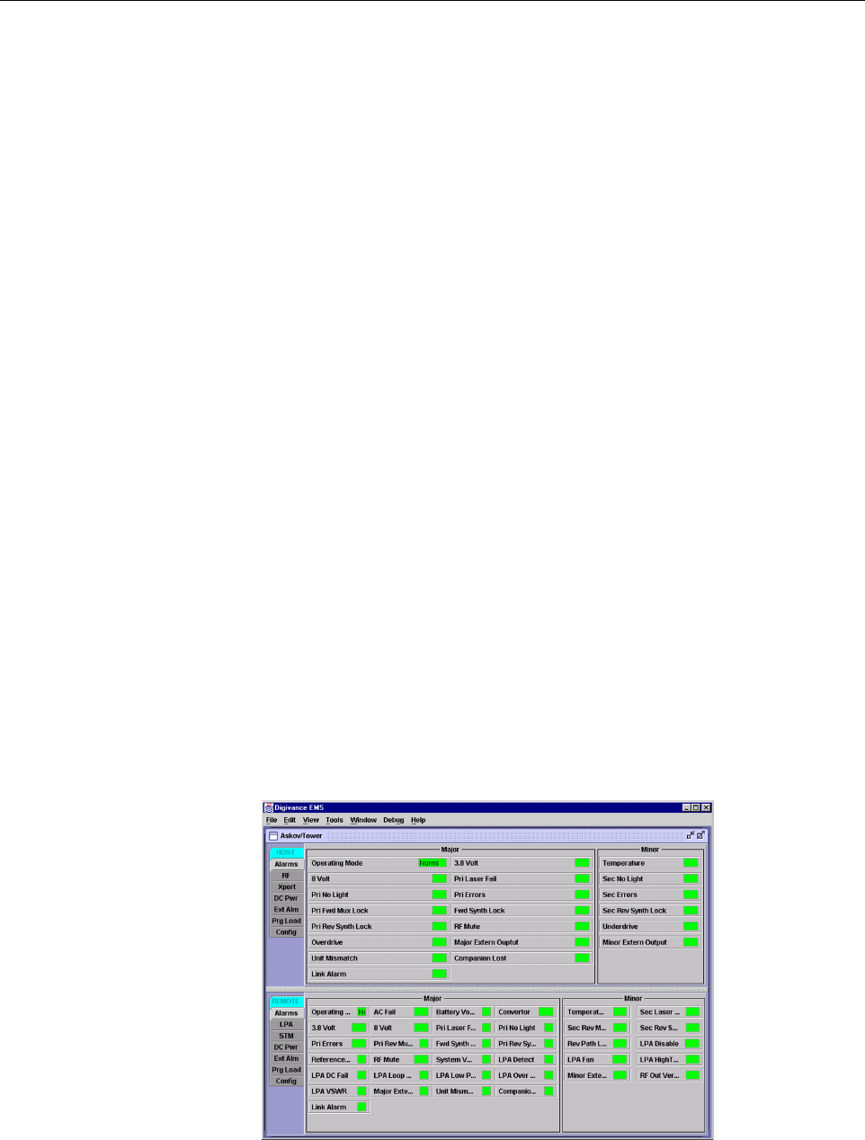
The GUI is presented at the DEMS computer or on alaptop computer. The GUI is used for local
control and monitoring operations. The GUI consists of aseries of displays and screens, such as
the one shown in Figure 2-18,that provide the user with alarm and status information and that
allow the user to set various operating parameters.
Figure 2-18. DEMS Graphical User Interface Host/Remote Display