ADC Telecommunications DLC0802A Digivance 800 MHz 20 Watts System User Manual 75150
ADC Telecommunications Inc Digivance 800 MHz 20 Watts System 75150
Contents
manual5
ADCP-75-150 • Preliminary Issue A • March 2003 • Section 4: Operation
Page 4-6
©2003, ADC Telecommunications, Inc.
2.2 Verify/Download HU and RU System Software
The HU’s and RU’s may require asystem software download if they are not loaded with the
current system software. Use the following procedure to check the version number of the
system software and if necessary to download the current system software:
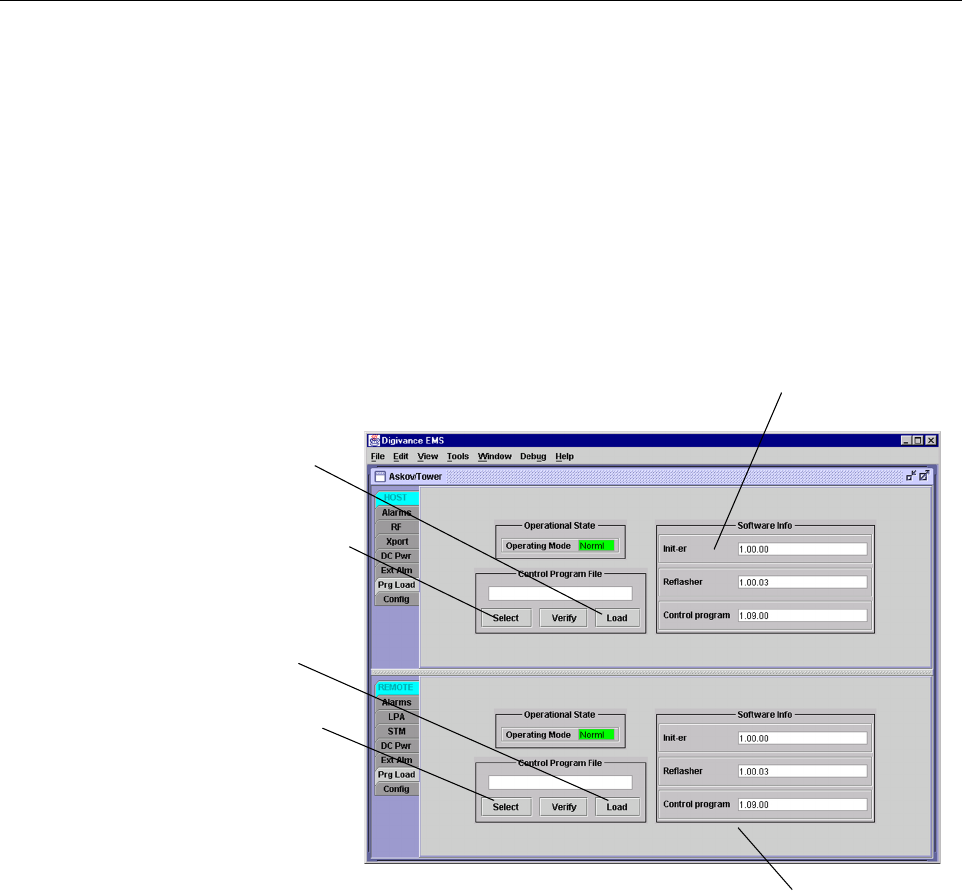
1. Click on the HOST Prg Load tab and on the REMOTE Prg Load tab. The HOST Prg
Load display and the Remote Prg Load display will open within the DEMS main window
as shown in Figure 4-3.
Figure 4-3. HOST and REMOTE Prg Load Displays
2. Click on the HOST Select button (see Figure 4-3). The Select Control Program File
window will open as shown in Figure 4-4.Browse until the folder where the Control
Program files are located is selected and the software files are displayed in the window.
Click to open Select Control
Program window for HOST
Click to start down-
load to HOST.
Click to start down-
load to REMOTE.
Click to open Select
Control Program win-
dow for REMOTE.
Verify software version
before starting download.
Verify software version
before starting download.
FCC ID: F8I-DLC0802A User Manual - Part 5
ADCP-75-150 • Preliminary Issue A • March 2003 • Section 4: Operation
Page 4-7
©2003, ADC Telecommunications, Inc.
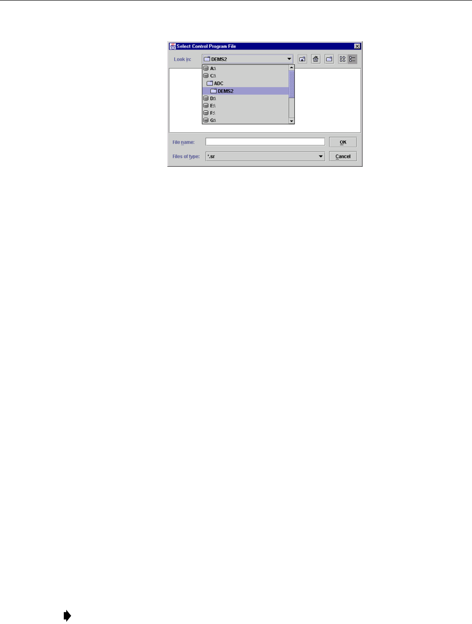
Figure 4-4. Select Control Program File Window
3. Check the software version numbers shown in the Software Info section of the Prg Load
display against the version numbers of the software files displayed in the Select Control
Program File window. If files in the Select Control Program File window are alater
version than those shown in the Prg Load display, proceed with the software download. If
the version numbers shown in the Software Info section are the same as the version
numbers of the files in the Select Control Program File window, the software download
is not required.
4. Select the required file to download and click on the OK button.
5. Click on the HOST Load button (see Figure 4-3)to start the download.
6. Repeat steps 2through 4for the REMOTE.
2.3 Determine Forward Path Input Signal Level
The level of the composite RF input signal at the FORWARD RF IN port at the HU will vary
depending on the type of BTS, the cable loss, the number of channels present, and the required
forward path composite power. If maximum composite RF output is required, the signal level of
the composite forward path RF signal at the HU forward path input must be adjusted to fall
within arange of –10 to –40 dBm.If the signal level is not within this range, it must be adjusted
to fall within this range through the use of an external attenuator capable of handling the BTS
forward path output power.
If using the Conditioning Panel or Duplexing Panel, refer to the Digivance 800 and 1900 MHz
Interface Panels User Manual (ADCP-75-147) for the procedures for measuring and adjusting
the input RF signal level at the HU. If connecting asingle HU to asingle BTS, use the following
procedure to measure and adjust the input RF signal level at the HU:
1. Connect aspectrum analyzer or power meter to the forward path output port of the BTS.
The required signal levels and test points are shown in Figure 4-5.
Note: Check the input rating of the test equipment and the output rating of the BTS. To
avoid burning out the spectrum analyzer or power meter, it may be necessary to insert a
30 dB 100W (or similar) attenuator between the BTS and test equipment.

ADCP-75-150 • Preliminary Issue A • March 2003 • Section 4: Operation
Page 4-8
©2003, ADC Telecommunications, Inc.
2. If using aspectrum analyzer, proceed to step 3. If using apower meter, measure the
composite signal power from the BTS and then proceed to step 5.
3. Measure the RF level of asingle carrier, such as the control channel, in dBm. Make sure
the resolution bandwidth of the spectrum analyzer is 30 kHz. Maximum power in any
channel should not exceed 5W (+37 dB).
4. Calculate the total composite signal power from the BTS using the following formula:
Ptot = Pc+10Log N – (see Note)
Where,
Ptot is the total composite power in dBm
Pcis the power per carrier in dBm as measured in step 3, and
Nis the total number of channels.
5. Determine the total cable loss that is imposed by the forward path coaxial cable that links
the BTS to the HU and also any insertion loss imposed by splitters or combiners.
6. Subtract the total cable loss and any insertion losses from the total composite power
calculated in step 4.
7. Subtract –25 (midpoint of the required range) from the value determined in step 6. The
difference (which should be positive) equals the value of the external attenuator that is
required to reduce the forward path signal level to fall within the required range. The
following formula outlines the required calculations for steps 6and 7:
Ptot – (Cable and insertion loss) –(–25) =Value of external attenuator required
8. Select an attenuator that is as close to the value calculated in step 7as possible. Select a
value that will adjust the signal level of the composite input signal to fall within the
specified range.
9. Install the external attenuator in the coaxial cable that is connected to the FORWARD RF
IN port at the HU.
10. Subtract the value of the external attenuator used in step 9from the total composite signal
power (Ptot)and record the result. This value will be required when setting the attenuation
of the HU’s internal forward attenuator.
Note: If calculating the composite power for aCDMA system, reduce the initial result by
16.23 dBm
Note: If the input signal level is already within the required range of –10 to –40 dBm, then
no external attenuator is required.
Caution: The Host Unit can be damaged if it is overdriven by the BTS. Always install an
external protective attenuator at the Host Unit FORWARD RF IN port if the forward path
composite input signal level is greater than –10 dBm.
ADCP-75-150 • Preliminary Issue A • March 2003 • Section 4: Operation
Page 4-9
©2003, ADC Telecommunications, Inc.
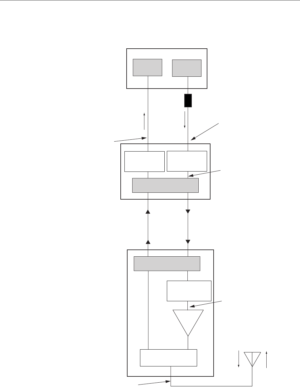
Figure 4-5. Signal Levels, Test Points, and Adjustments
INPUT SIGNAL LEVEL
(-25 dBm TYPICAL
COMPOSITE FOR
FULL POWER)
HOST UNIT
PRIMARY
ANTENNA
LPA
REMOTE UNIT
EXTENDED BASE
TRANSCEIVER STATION
17000-B
EXTERNAL
ATTENUATOR
TRANS-
MITTERS
RECEIVERS
0 to 30 dB
ATTENUATOR
(HOST REV ATT)
0 to 30 dB
ATTENUATOR
(HOST FWD ATT)
RF, OPTICS,
AND CONTROL
0 to 30 dB
ATTENUATOR
(REMOTE FWD ATT)
OPTICAL LINK
RF, OPTICS,
AND CONTROL
DUPLEXER
ADJUSTMENTS TO INPUT
SIGNAL LEVEL AS SET BY HOST
FORWARD PATH ATTENUATOR
ADJUSTMENTS TO OUTPUT
SIGNAL LEVEL AS SET BY HOST
REVERSE PATH ATTENUATOR
MAXIMUM OUTPUT SIGNAL
LEVEL AT STM ANTENNA PORT
ADJUSTMENTS TO
OUTPUT SIGNAL LEVEL
AS SET BY THE REMOTE
FORWARD ATTENUATOR
ADCP-75-150 • Preliminary Issue A • March 2003 • Section 4: Operation
Page 4-10
©2003, ADC Telecommunications, Inc.
2.4 Enter Site Name and Site Number
All HU’s and RU’s are programmed with the same site name and site number. It is therefore
necessary to assign aunique site name and site number to the HU and RU before they can be
connected to the same CAN. Use the following procedure to assign aunique site name and
number to each HU and RU system:
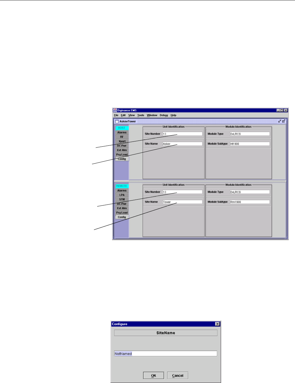
1. Click on the HOST Config tab and on the REMOTE Config tab. The HOST Config
display and the REMOTE Config display will open within the DEMS main window as
shown in Figure 4-6.
Figure 4-6. HOST and REMOTE Config Displays
2. Right-click on the HOST Site Name field (see Figure 4-6). The Site Name pop-up screen
will open as shown in Figure 4-7.Enter aunique name for the HOST. The name may be up
to 32 characters long and must not contain any spaces. The name may include numbers,
punctuation, and upper or lower case letters and must always begin with aletter. Click on
OK to close the screen and make the changes take effect.
Figure 4-7. HOST Site Name Pop-Up Screen
HOST Site Number
HOST Site Name
REMOTE Site Number
(Entered automatically
when the HOST site
number is selected)
REMOTE Site Name
Right-Click on the
point shown to open
pop-up screen

ADCP-75-150 • Preliminary Issue A • March 2003 • Section 4: Operation
Page 4-11
©2003, ADC Telecommunications, Inc.
3. Right-click on the HOST Site Number (see Figure 4-6). The Site Number pop-up screen
will open. Enter any number between 1and 24 and then click on OK to close the screen
and make the changes take effect.
4. Check the REMOTE Site Number field (see Figure 4-6). The REMOTE Site Number
does not have to be entered. When the HOST Site Number is entered, the system will
automatically enter the same number for the REMOTE Site Number.
5. Right-click on the REMOTE Site Name field (see Figure 4-6). The Site Name pop-up
screen will open. Enter aunique name for the REMOTE. The name may be up to 32
characters long and must not contain any spaces. The name may include numbers,
punctuation, and upper or lower case letters and must always begin with aletter. Click on
OK to close the screen and make the changes take effect.
6. Open the Tools menu at the top of the main window and then select Refresh Catalog to
make the new Host and Remote site names appear in the View menu.
2.5 Enter Host Forward Attenuation
The HU internal forward path attenuator setting determines the maximum composite output
signal level at the STM antenna port. The appropriate attenuation value for any particular
system is based on the number of channels the system is transporting and the level of the
composite forward path signal input at the HU’s FORWARD RF IN port. The maximum output
power that can be provided by the system is 40.5 dBm (11 Watts). The total forward path gain
that is provided by the system (with host and remote forward attenuators set to 0dB) is 80.5
dBm. Use the following procedure to set the forward path attenuation to provide the maximum
composite output signal level:
1. Click on the HOST RF tab. The HOST RF display will open within the DEMS main
window as shown in Figure 4-8.
2. Right-click on the Host Fwd Att section of the display (see Figure 4-8). The Host Fwd
Att pop-up screen will open as shown in Figure 4-9.
3. Obtain the value of the total composite input signal level as determined in step 10 of
Section 2.3.
4. Determine the appropriate value to enter for the Host forward path attenuator by
subtracting the required system output level (per system design plan) from 80.5 (the total
system gain) and then adding the composite input signal level. The result (see sample
calculation) is the amount of attenuation required.
Atten Required =80.5 –(Required System Output Power) +(Composite Input Power)
5. Enter the attenuation value and click OK to close the pop-up screen and to make the
changes take effect.