Alcatel Lucent USA ONEBTS-11 UMTS-CDMA Transceiver System (850) User Manual 401703454i1
Alcatel-Lucent USA Inc. UMTS-CDMA Transceiver System (850) 401703454i1
Contents
users manual f
3-32 Lucent Technologies – Proprietary
See notice on first page 401-703-454
FOA Draft Issue 1
January, 2006
...........................................................................................................................................................................................................................................................
Cable connections in the Modular Cell 4.0B cabinets
As the dome is tightened, the fingers at the top of the flex fitting are
compressed against the rubber strain relief insert, which is, in turn,
compressed against the cable insulation. Simultaneously, the nickel-
plated EMI spring fingers at the bottom of the flex fitting are
compressed against the exposed cable shield. The EMI spring fingers
are grounded to the feed-through body, which, in turn, is bonded to the
cabinet enclosure. This effectively grounds the cable shield.
................................................................................................................................
............................................
10 Repeat Steps 1 through 9 for all T1/E1 and user alarm cables and then
replace the top cover on the antenna cable cover.
Use the following procedure to prepare the T1/E1 and user alarm
cables for punchdown and ground connection at the facilities interface
panel.
Cable connections in the Modular Cell 4.0B cabinets
3- 33
Lucent Technologies – Proprietary
See notice on first page
401-703-454
FOA Draft Issue 1
January, 2006
............................................................................................................................................................................................................................................................
Prepare the T1/E1 and user
alarm cables for
punchdown and ground
connection at the facilities
interface module
Prepare the T1/E1 and user alarm cables for punchdown at the EFIM
(facilities interface module). User alarm cables are attached only at the
primary cabinet.
................................................................................................................................
............................................
1Allow adequate slack and cut the T1/E1 and user alarm cable to the
correct length.
................................................................................................................................
............................................
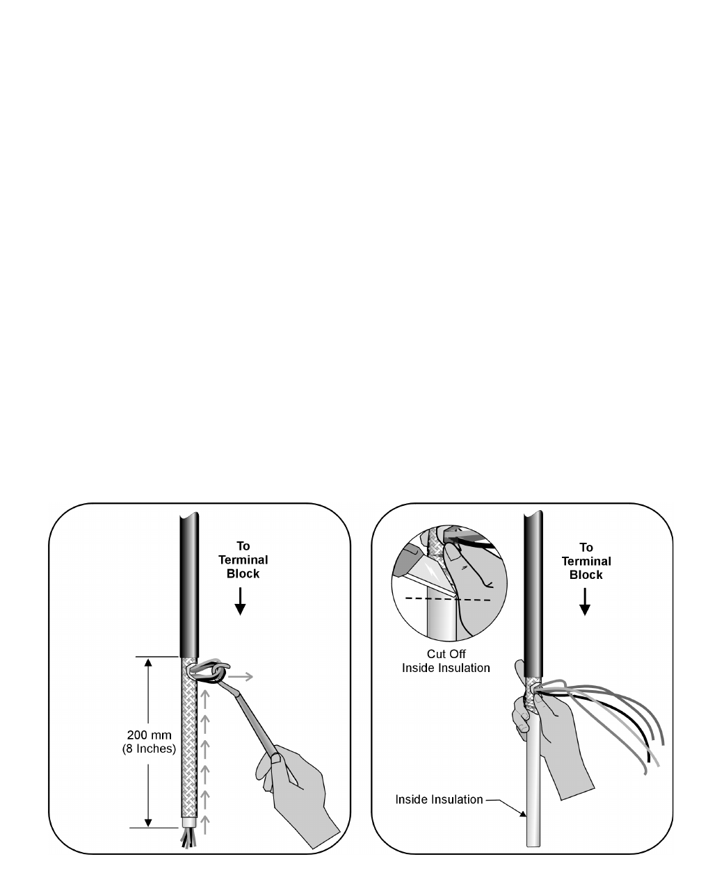
2Strip the outer cable insulation to expose 200 mm (8 inches) of the
braided shield. Refer to the figure below.
Important! Be careful not to cut into the cable shield.
................................................................................................................................
............................................
3At the end of the outer insulation, cut an opening in the braided shield,
and the insulation inside it, to expose the individual wires.
................................................................................................................................
............................................
4Using a hook or equivalent tool, pull the wires out through the opening
made in the previous step, as shown in the figure below.
3-34 Lucent Technologies – Proprietary
See notice on first page 401-703-454
FOA Draft Issue 1
January, 2006
...........................................................................................................................................................................................................................................................
Cable connections in the Modular Cell 4.0B cabinets
................................................................................................................................
............................................
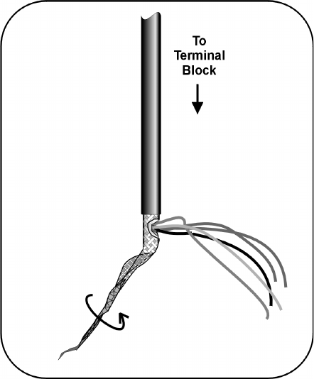
5Push the braided shield back on the inside insulation as shown.
................................................................................................................................
............................................
6Cut off the exposed inside insulation.
................................................................................................................................
............................................
7Twist the T1/E1 and user alarm cable shields at the end of the cables in
preparation for their attachment to a grounding clamp located on the
facilities interface module. Refer to the figure below.
................................................................................................................................
............................................
8Repeat steps 1 through 7 for each cable.
................................................................................................................................
............................................
9Quality Check - Verify the following.
1. Check that all cables are firmly held by the seal and is not loose.
2. Using an ohmmeter, check continuity between the frame and the
cable shield at the end of each cable to ensure that it is bonded in
the cord grip seal.

Cable connections in the Modular Cell 4.0B cabinets
3- 35
Lucent Technologies – Proprietary
See notice on first page
401-703-454
FOA Draft Issue 1
January, 2006
............................................................................................................................................................................................................................................................
Connection of T1/E1 Lines to the EFIM punchdowns in Modular Cell
.............................................................................................................................................................................................................................................................
4.0B cabinets
Overview This procedure module provides instructions for connecting of the T1/
E1 cables in a Modular Cell 4.0B primary or 4.0B dual band cabinet
T1/E1 installation will vary depending upon the Universal Radio
Controller (URC or URCII) in use in the cabinet being installed. A
URC accepts a maximum of twelve TI/E1 lines (one cable). A URCII
accepts a maximum of twenty TI/E1 lines (two cables).
Instructions are provided for 4.0B cabinets that have a maximum of
twelve T1/E1 lines, as well as for 4.0B cabinets that have a maximum
of twenty T1/E1 lines. 4.0B cabinets that have a maximum of twenty
T1/E1 lines have a different EFIM (POD B has been added) for internal
punch down of T1/E1 and user alarm cables.
Punch down T1/E1 lines on the EFIM in Modular Cell 4.0B
cabinets that accept a maximum of twelve T1/E1 lines
3 - 36
Punch down T1/E1 lines on the EFIM in Modular Cell 4.0B
cabinets that accept a maximum of twenty T1/E1 lines
3 - 41
3-36 Lucent Technologies – Proprietary
See notice on first page 401-703-454
FOA Draft Issue 1
January, 2006
...........................................................................................................................................................................................................................................................
Cable connections in the Modular Cell 4.0B cabinets
Punch down T1/E1 lines on
the EFIM in Modular Cell
4.0B cabinets that accept a
maximum of twelve T1/E1
lines
Important! If installing a Modular Cell 4.0B cabinet that
accepts a maximum of twenty T1/E1 lines, skip to Punch down T1/
E1 lines on the EFIM in Modular Cell 4.0B cabinets that accept a
maximum of twenty T1/E1 lines on Page 3 - 41 and continue the
installation from that point.
Some Modular Cell 4.0B primary or dual band cabinets are equipped
with USRs (Universal Radio Controllers) as opposed to UCRlls. These
Modular Cell 4.0B cabinets accepts a maximum of twelve T1/E1 lines.
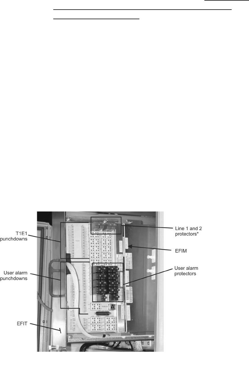
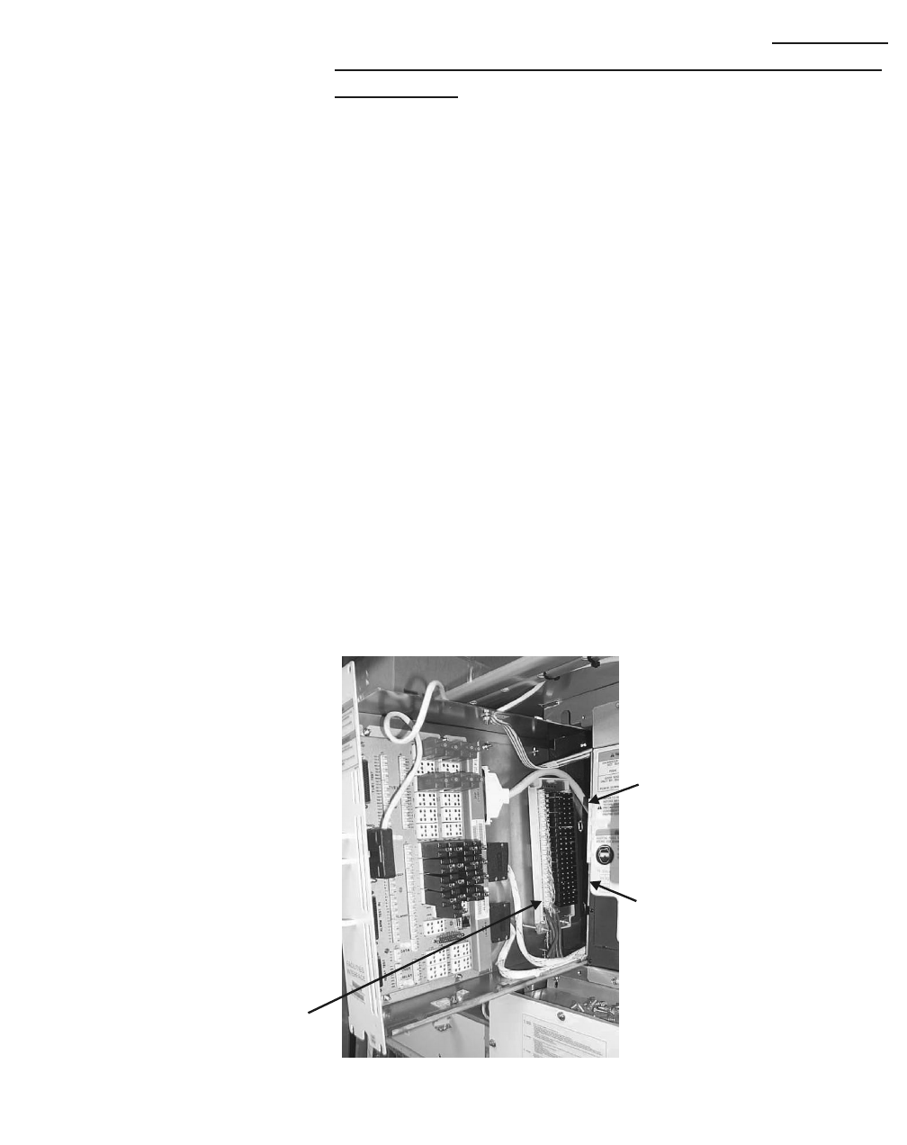
The T1/E1 lines will be connected to the punchdown terminals on the
EFIM (facilities interface module) inside of the Modular Cell 4.0B
primary or dual band cabinet. The EFIM is accessible from the front of
the cabinet, behind a slide-out tray (EFIT - facilities interface tray). See
the figure below. Use the following procedure to punch down the T1/
E1 lines on the EFIM in the applicable Modular Cell 4.0B cabinet.
Refer to the figure below.
................................................................................................................................
............................................
1Open the facilities interface tray. Refer to the figure below.
................................................................................................................................
............................................
2Connect the twisted ends of the T1/E1 cable shield to the grounding
clamp located on the EFIM. Refer to the figure below. Refer to the figure
on Page 3-38 for more detail.
* FOR PROTECTOR LOCATIONS OF ADDITIONAL T1/E LINES,
REFER TO THE FIGURE AND TABLES THAT FOLLOW

Cable connections in the Modular Cell 4.0B cabinets
3- 37
Lucent Technologies – Proprietary
See notice on first page
401-703-454
FOA Draft Issue 1
January, 2006
............................................................................................................................................................................................................................................................
Important! Before performing the next step, consult the
customer / site engineer for the site preparation data sheet that is
provided in the Flexent Modular Cell 4.0/4.0B Outdoor Site
Preparation Guidelines, 401-703-413. The site preparation data
sheet is provided to allow the customer a means to record the T1/
E1 line assignments for punchdown at the EFIM, and to convey
that information to the installer. The data should include the TX/
RX signal pair assignments and their color codes for each line
number to be attached. Note that the T1/E1 line numbers do not
correspond to the silk-screened TX/RX signal pair labels on the
EFIM. Also note that the TX and RX punchdowns TX1/RX1
through TX12/RX12,are not located in numerically consecutive
order.
................................................................................................................................
............................................
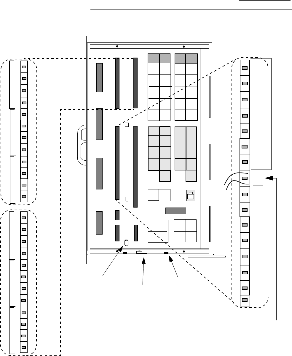
3Connect the T1/E1 wire pairs as follows. Refer to the figure on Page 3-
38, Note 1, and the table on Page 3 - 39.
• Connect the applicable T1/E1 wire pairs to connector J1 and J2
punchdowns, signals TX1/RX1 through TX12/RX12, as assigned
by the customer on the site preparation data sheet.
................................................................................................................................
............................................
4Check that two surge protectors are installed in the correct protector
locations for each installed line. Refer to the figure on Page 3-38, and
the table on Page 3 - 39.
................................................................................................................................
............................................
5Close and secure the EFIT with the four screws.
3-38 Lucent Technologies – Proprietary
See notice on first page 401-703-454
FOA Draft Issue 1
January, 2006
...........................................................................................................................................................................................................................................................
Cable connections in the Modular Cell 4.0B cabinets
................................................................................................................................
............................................
6After completion of the T1/E1 punchdowns, skip to Connection of user
alarms to the EFIM punchdown blocks in the Modular Cell 4.0B primary cabinet
on Page 3 - 48 to punchdown the user alarms.
J1
J4
J3
J5
NOTE 2
USER ALARM
CONNECTIONS
GROUND
CLAMP
NOTE 1
T1/E1
CONNECTIONS
• All punchdown
connections will
accept 24 AWG solid
wires.
J6
J7
J2
CABLE
TIE_DOWN
POINT
(1 of 3)
TX7
TX12
TX1
TX6
0+
15-
33-
16+
J8A J8B J8C J8D
J9A J9B J9C J9D
J10A J10B J10C J10D
TX1
TX7
TX3
TX9
TX5
TX11
TX2
TX8
TX4
TX10
TX6
TX12
RX1 RX2
RX7 RX8
RX3 RX4
RX9 RX10
RX5 RX6
RX11 RX12
0+
0-
1+
1-
2+
2-
3+
3-
4+
4-
5+
5-
6-
6+
7+
7-
8+
8-
9+
9-
10+
10-
11+
11-
12+
12-
13+
13-
14+
14-
15+
15-
0+
2+
4+
6+
8+
10+
12+
14+
16+
18+
20+
22+
24+
26+
28+
30+
32+
UR1
UR2
UR3
UR4
UR5
UR0 UR6
UR7
CABLE
TIE-DOWN
POINT
(1 of 2)
START AT PUNCH-
DOWN PAIR 7 ON J3,
AND CONTINUE ON
J4 AFTER PAIR 15.
U
S
E
D
F
O
R
I
N
T
E
R
N
A
L
P
O
W
E
R
A
L
A
R
M
S
1+
3+
5+
7+
9+
11+
13+
17+
19+
21+
23+
25+
27+
29+
31+
33+
0-
to
33-
15+
J2
J1 J3
RX9
TX9
T
R
TX10
RX10
TX5
RX5
TX6
RX6
T
R
T
R
T
R
T
R
T
R
T
R
T
R
T
R
T
R
T
R
T
R
RX11
RX12
TX11
TX12
L
L
L
L
L
L
RX1
TX1
T
R
TX2
RX2
TX7
RX7
TX8
RX8
T
R
T
R
T
R
T
R
T
R
T
R
T
R
T
R
T
R
T
R
T
R
RX3
RX4
TX3
TX4
L
L
L
L
L
L
Cable connections in the Modular Cell 4.0B cabinets
3- 39
Lucent Technologies – Proprietary
See notice on first page
401-703-454
FOA Draft Issue 1
January, 2006
............................................................................................................................................................................................................................................................
The following table provides the EFIM punchdown terminal block TX/
RX signal pair connections to their associated URCs: 1, 2, or 3. T1/E1
lines 1 through 12 are connected to these punchdowns (as assigned by
the customer) in the Modular Cell 4.0B cabinets.
T1/E1 Line
Assignment
Terminal Block
Pair/ Tip Ring
NOTE 3
"J"
Conn.
Block
C/C Protector
Location URC
Position
number
Line __ TX1-T (Top)
J1 Blue
J8A/TX-1 URC,
Position 1
NOTE 1
TX1-R (Bottom)
RX1-T (Top)
Orange
J8B/RX-1
RX1-R (Bottom)
Line __ TX2-T (Top)
J1
Green
J8C/TX-2
TX2-R (Bottom)
RX2-T (Top)
Brown
J8D/RX-2
RX2-R (Bottom)
Line __ TX7-T (Top)
J1 Blue
J8A/TX-7 URC,
Position 2
NOTE 2
TX7-R (Bottom)
RX7-T (Top)
Orange
J8B/RX-7
RX7-R (Bottom)
Line __ TX8-T (Top)
J1 Green
J8C/TX-8
TX8-R (Bottom)
RX8-T (Top)
Brown
J8D/RX-8
RX8-R (Bottom)
Line __ TX3-T (Top)
J1 Blue
J8A/TX-3 URC,
Position 1
NOTE 1
TX3-R (Bottom)
RX3-T (Top)
Orange
J8B/RX-3
RX3-R (Bottom)
Line __ TX4-T (Top)
J1 Green
J8C/TX-4
TX4-R (Bottom)
RX4-T (Top)
Brown
J8D/RX-4
RX4-R (Bottom)
NOTE 1: A DATA T1/E1 line must
be punched down to URC, position 1
(
TX-RX 1 to TX-RX 4). VOICE T1/E1 lines may also be punched down to URC, position 1
(TX-RX 1 to TX-RX 4) but Data and Voice are mutually exclusive.
NOTE 2: VOICE T1/E1 lines only are punched down to URC, position 2 (TX-RX 5 to TX-
RX 8) and URC, position 3 (TX-RX 9to TX-RX 12)
NOTE 3:
TX/RX signal pair punchdowns are not physically located in numerically
consecutive order on the EFIM.
3-40 Lucent Technologies – Proprietary
See notice on first page 401-703-454
FOA Draft Issue 1
January, 2006
...........................................................................................................................................................................................................................................................
Cable connections in the Modular Cell 4.0B cabinets
T1/E1 Line
Assignment
Terminal Block
Pair/ Tip Ring
NOTE 3
"J"
Conn.
Block
C/C Protector
Location
URC
Position
number
Line __ TX9-T (Top)
J2 Blue
J8A/TX-9 URC,
Position 3
NOTE 2
TX9-R (Bottom)
RX9-T (Top)
Orange
J8B/RX-9
RX9-R (Bottom)
Line __ TX10-T (Top)
J2 Green
J8C/TX-10
TX10-R (Bottom)
RX10-T (Top) Brown J8D/RX-10
RX10-R (Bottom)
Line __ TX5-T (Top)
J2 Blue
J8A/TX-5 URC,
Position 2
NOTE 2
TX5-R (Bottom)
RX5-T (Top)
Orange
J8B/RX-5
RX5-R (Bottom)
Line __ TX6-T (Top)
J2 Green
J8C/TX-6
TX6-R (Bottom)
RX6-T (Top) Brown J8D/RX-6
RX6-R (Bottom)
Line __ TX11-T (Top)
J2 Blue
J8A/TX-11 URC,
Position 3
NOTE 2
TX11-R (Bottom)
RX11-T (Top)
Orange
J8B/RX-11
RX11-R (Bottom)
Line __ TX12-T (Top)
J2 Green
J8C/TX-12
TX12-R (Bottom)
RX12-T (Top) Brown J8D/RX-12
RX12-R (Bottom)
NOTE 1: A DATA T1/E1 line must be punched down to URC, position 1
(
TX-RX 1 to TX-RX 4). VOICE T1/E1 lines may also be punched down to URC, position 1
(TX-RX 1 to TX-RX 4) but Data and Voice are mutually exclusive.
NOTE 2: VOICE T1/E1 lines only are punched down to URC, position 2 (TX-RX 5 to TX-
RX 8) and URC, position 3 (TX-RX 9to TX-RX 12)
NOTE 3:
TX/RX signal pair punchdowns are not physically located in numerically
consecutive order on the EFIM
Cable connections in the Modular Cell 4.0B cabinets
3- 41
Lucent Technologies – Proprietary
See notice on first page
401-703-454
FOA Draft Issue 1
January, 2006
............................................................................................................................................................................................................................................................
Punch down T1/E1 lines on
the EFIM in Modular Cell
4.0B cabinets that accept a
maximum of twenty T1/E1
lines
Important! If installing a Modular Cell 4.0B cabinet that
accepts a maximum of twelve T1/E1 lines, skip to Connection of
user alarms to the EFIM punchdown blocks in the Modular Cell 4.0B
primary cabinet on Page 3 - 48 to punchdown the user alarms.
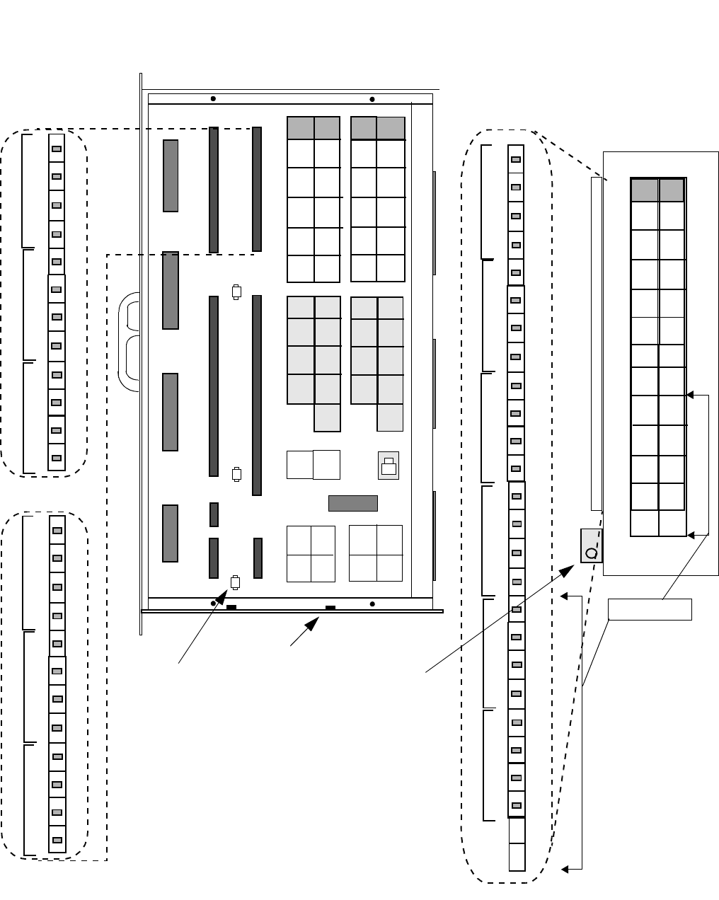
Some Modular Cell 4.0B primary or dual band cabinets are equipped
with USRlls (Universal Radio Controllers) as opposed to UCRs. These
Modular Cell 4.0B cabinets accepts a maximum of twenty T1/E1 lines.
The T1/E1 lines will be connected to the punchdown terminals on the
EFIM (facilities interface module) inside of the Modular Cell 4.0B
primary or dual band cabinet. The EFIM is accessible from the front of
the cabinet, behind a slide-out tray (EFIT - facilities interface tray). See
the figure below. Use the following procedure to punch down the T1/
E1 lines on the EFIM in the applicable Modular Cell 4.0B cabinet.
Refer to the figure below.
................................................................................................................................
............................................
1Open the facilities interface tray. Refer to the figure below.
................................................................................................................................
............................................
2Connect the twisted ends of the T1/E1 and user alarm cable shields to
the grounding clamp located on the EFIM. Refer to the figure below.
Refer to the figure on Page 3-43 for more detail.
POD B (4.0B With URCIIs
Only)
Added for T1/E1 pairs
13 through 20
POD B Protectors for
T1/E1 pairs 13 through
POD B Punchdowns for
T1/E1 pairs 13 through 20

3-42 Lucent Technologies – Proprietary
See notice on first page 401-703-454
FOA Draft Issue 1
January, 2006
...........................................................................................................................................................................................................................................................
Cable connections in the Modular Cell 4.0B cabinets
Important! Before performing the next step, consult the
customer / site engineer for the site preparation data sheet that is
provided in the Flexent Modular Cell 4.0/4.0B Outdoor Site
Preparation Guidelines, 401-703-413. The site preparation data
sheet is provided to allow the customer a means to record the T1/
E1 line assignments for punchdown at the EFIM, and to convey
that information to the installer. The data should include the TX/
RX signal pair assignments and their color codes for each line
number to be attached. Note that the T1/E1 line numbers do not
correspond to the silk-screened TX/RX signal pair labels on the
EFIM. Also note that the TX and RX punchdowns TX1/RX1
through TX12/RX12,are not located in numerically consecutive
order.
................................................................................................................................
............................................
3Connect the T1/E1 wire pairs TX1/RX1 through TX12/RX12 as
follows. Refer to the figure on Page 3-43, Note 1, and the table on Page
3 - 44.
• Connect the applicable T1/E1 wire pairs to connector J1 and J2
punchdowns, signals TX1/RX1 through TX12/RX12, as assigned
by the customer on the site preparation data sheet.
................................................................................................................................
............................................
4Connect the T1/E1 wire pairs TX13/RX13 through TX20 /RX20 as
follows. Refer to the figure on Page 3-43, Note 2, and the table on Page
3 - 44.
• Connect the applicable T1/E1 wire pairs to Pod B connector
punchdowns 13 through 20, signals TX13/RX13 through TX20/
RX20, as assigned by the customer on the site preparation data
sheet.
................................................................................................................................
............................................
5Check that two surge protectors are installed in the correct protector
locations for each installed line. Refer to the figure on Page 3-43, and
the table on Page 3 - 44.
Cable connections in the Modular Cell 4.0B cabinets
3- 43
Lucent Technologies – Proprietary
See notice on first page
401-703-454
FOA Draft Issue 1
January, 2006
............................................................................................................................................................................................................................................................
................................................................................................................................
............................................
6Close and secure the EFIT with the four screws.
J1
J4
J3
J5
RX1
TX1
T
R
TX2
RX2
TX7
RX7
TX8
RX8
NOTE 1: T1/E1
CONNECTIONS
TX/RX 1-12
• All punchdown
connections will
accept 24 AWG solid
wires.
T
R
T
R
T
R
T
R
T
R
T
R
T
R
T
R
T
R
T
R
T
R
RX3
RX4
TX3
TX4
J6
J7
J2
CABLE
TIE_DOWN
POINT
(1 of 3)
TX7
TX12
TX1
TX6
0+
15-
33-
16+
J8A J8B J8C J8D
J9A J9B J9C J9D
J10A J10B J10C J10D
TX1
TX7
TX3
TX9
TX5
TX11
TX2
TX8
TX4
TX10
TX6
TX12
RX1 RX2
RX7 RX8
RX3 RX4
RX9 RX10
RX5 RX6
RX11 RX12
0+
2+
4+
6+
8+
10+
12+
14+
16+
18+
20+
22+
24+
26+
28+
30+
32+
UR1
UR2
UR3
UR4
UR5
UR0 UR6
UR7
CABLE
TIE-DOWN
POINT
(1 of 2)
1+
3+
5+
7+
9+
11+
13+
17+
19+
21+
23+
25+
27+
29+
31+
33+
0-
to
33-
15+
RX9
TX9
T
R
TX10
RX10
TX5
RX5
TX6
RX6
T
R
T
R
T
R
T
R
T
R
T
R
T
R
T
R
T
R
T
R
T
R
RX11
RX12
TX11
TX12
J2
J1
L
RX19
TX19
T
R
TX20
RX20
TX21
RX21
TX22
RX22
T
R
T
R
T
R
T
R
T
R
T
R
T
R
T
R
T
R
T
R
T
R
RX23
RX24
TX23
TX24
L
L
L
L
L
L
L
L
L
L
L
L
L
L
L
L
L
RX13
TX13
T
R
TX14
RX14
TX15
RX15
TX16
RX16
T
R
T
R
T
R
T
R
T
R
T
R
T
R
T
R
T
R
T
R
T
R
RX17
RX18
TX17
TX18
L
L
L
L
L
L
NOTE 2: T1/E1
CONNECTIONS
TX/RX 13-24
JXA JXB
TX13
TX14
TX15
TX16
TX17
TX18
RX13
RX14
RX15
RX16
RX17
RX18
TX19
TX20
TX21
TX22
TX23
TX24
RX19
RX20
RX21
RX22
RX23
RX24
NOT USED
POD B
GROUND
CLAMP
3-44 Lucent Technologies – Proprietary
See notice on first page 401-703-454
FOA Draft Issue 1
January, 2006
...........................................................................................................................................................................................................................................................
Cable connections in the Modular Cell 4.0B cabinets
The following table provides the EFIM punchdown terminal block TX/
RX signal pair connections to their associated URC IIs: Positions 1, 2,
or 3. T1/E1 lines 1 through 20 are connected to these punchdowns (as
assigned by the customer) in the Modular Cell 4.0B cabinets.
T1/E1 Line
Assignment
Terminal Block
Pair/ Tip Ring
NOTE 3
"J"
Conn. Block
C/C Protector
Location URC II
POSITION #
NOTE 3
Line __ TX1-T (Top)
J1 Blue
J8A/TX-1
URC II,
Position 1
NOTE 1
TX1-R (Bottom)
RX1-T (Top)
Orange
J8B/RX-1
RX1-R (Bottom)
Line __ TX2-T (Top)
J1
Green
J8C/TX-2
TX2-R (Bottom)
RX2-T (Top)
Brown
J8D/RX-2
RX2-R (Bottom)
Line __ TX7-T (Top)
J1 Blue
J8A/TX-7
URC II,
Position 2
NOTE 2
TX7-R (Bottom)
RX7-T (Top)
Orange
J8B/RX-7
RX7-R (Bottom)
Line __ TX8-T (Top)
J1 Green
J8C/TX-8
TX8-R (Bottom)
RX8-T (Top)
Brown
J8D/RX-8
RX8-R (Bottom)
Line __ TX3-T (Top)
J1 Blue
J8A/TX-3
URC II,
Position 1
NOTE 1
TX3-R (Bottom)
RX3-T (Top)
Orange
J8B/RX-3
RX3-R (Bottom)
Line __ TX4-T (Top)
J1 Green
J8C/TX-4
TX4-R (Bottom)
RX4-T (Top)
Brown
J8D/RX-4
RX4-R (Bottom)
NOTE 1: DATA T1/E1 lines must be punched down to URCII, position 1 only (TX-RX 1
to TX-RX 4) and (TX-RX 13 to TX-RX 16)
VOICE T1/E1 lines may also be punched down to URCII, position 1
but Data and Voice lines are mutually exclusive.
NOTE 2: Only VOICE T1/E1 lines are punched down to URC, position 2, (TX-RX 5 to
TX-RX 8) and (TX-RX 17 and TX-RX 18), as well as URC, position 3 (TX-RX 9 to
TX-RX 12) and (TX-RX 19 and TX-RX 20)
NOTE 3: TX/RX signal pair punchdowns TX-RX 1 to TX-RX 12 are not physically
located in numerically consecutive order on the EFIM.
Cable connections in the Modular Cell 4.0B cabinets
3- 45
Lucent Technologies – Proprietary
See notice on first page
401-703-454
FOA Draft Issue 1
January, 2006
............................................................................................................................................................................................................................................................
T1/E1 Line
Assignment
Terminal Block
Pair/ Tip Ring
NOTE 2
"J"
Conn.
Block
C/C Protector
Location URC II
POSITION #
NOTE 2
Line __ TX9-T (Top)
J2 Blue
J8A/TX-9
URC II,
Position 3
NOTE 1
TX9-R (Bottom)
RX9-T (Top)
Orange
J8B/RX-9
RX9-R (Bottom)
Line __ TX10-T (Top)
J2 Green
J8C/TX-10
TX10-R (Bottom)
RX10-T (Top) Brown J8D/RX-10
RX10-R (Bottom)
Line __ TX5-T (Top)
J2 Blue
J8A/TX-5
URC II,
Position 2
NOTE 1
TX5-R (Bottom)
RX5-T (Top)
Orange
J8B/RX-5
RX5-R (Bottom)
Line __ TX6-T (Top)
J2 Green
J8C/TX-6
TX6-R (Bottom)
RX6-T (Top) Brown J8D/RX-6
RX6-R (Bottom)
Line __ TX11-T (Top)
J2 Blue
J8A/TX-11
URC II,
Position 3
NOTE 1
TX11-R (Bottom)
RX11-T (Top)
Orange
J8B/RX-11
RX11-R (Bottom)
Line __ TX12-T (Top)
J2 Green
J8C/TX-12
TX12-R (Bottom)
RX12-T (Top) Brown J8D/RX-12
RX12-R (Bottom)
NOTE 1: Only VOICE T1/E1 lines are punched down to URC, position 2, (TX-RX 5 to
TX-RX 8) and (TX-RX 17 and TX-RX 18), as well as URC, position 3 (TX-RX 9 to TX-RX
12) and (TX-RX 19 and TX-RX 20)
NOTE 2: TX/RX signal pair punchdowns TX-RX 1 to TX-RX 12 are not physically
located in numerically consecutive order on the EFIM.
3-46 Lucent Technologies – Proprietary
See notice on first page 401-703-454
FOA Draft Issue 1
January, 2006
...........................................................................................................................................................................................................................................................
Cable connections in the Modular Cell 4.0B cabinets
T1/E1 Line
Assignment
Terminal Block
Pair/ Tip Ring
NOTE 3
"J"
Conn.
Block
C/C Protector
Location URC II
POSITION #
NOTE 3
Line __ TX13-T (Top)
N/A N/A
J
X
/TX-13
URC II,
Position 1
NOTE 1
TX13-R (Bottom)
RX13-T (Top)
N/A
J
X
/RX-13
RX13-R (Bottom)
Line __ TX14-T (Top)
N/A N/A
J
X
/TX-14
TX14-R (Bottom)
RX14-T (Top)
N/A
J
X
/RX-14
RX14-R (Bottom)
Line __ TX15-T (Top)
N/A N/A
J
X
/TX-15
URC II,
Position 1
NOTE 1
TX15-R (Bottom)
RX15-T (Top)
N/A
J
X
/RX-15
RX15-R (Bottom)
Line __ TX16-T (Top)
N/A N/A
J
X
TX-16
TX16-R (Bottom)
RX16-T (Top)
N/A
J
X
/RX-16
RX16-R (Bottom)
Line __ TX17-T (Top)
N/A N/A
J
X
/TX-17
URC II,
Position 2
NOTE 2
TX17-R (Bottom)
RX17-T (Top)
N/A
J
X
/RX-17
RX17-R (Bottom)
Line __ TX18-T (Top)
N/A N/A
J
X
/TX-18
TX18-R (Bottom)
RX18-T (Top)
N/A
J
X
/RX-18
RX18-R (Bottom)
NOTE 1: DATA T1/E1 lines must be punched down to URCII, position 1 only (TX-RX 1
to TX-RX 4) and (TX-RX 13 to TX-RX 16)
VOICE T1/E1 lines may also be punched down to URCII, position 1
but Data and Voice lines are mutually exclusive.
NOTE 2: Only VOICE T1/E1 lines are punched down to URC, position 2, (TX-RX 5 to
TX-RX 8) and (TX-RX 17 and TX-RX 18), as well as URC, position 3 (TX-RX 9 to
TX-RX 12) and (TX-RX 19 and TX-RX 20)
NOTE 3: POD B URCII assignments (TX-RX 13 to TX-RX 24). are located in the
s
ame order in the tables as their physical order on the EFIM. Refer to the figure on Page
3-38
Cable connections in the Modular Cell 4.0B cabinets
3- 47
Lucent Technologies – Proprietary
See notice on first page
401-703-454
FOA Draft Issue 1
January, 2006
............................................................................................................................................................................................................................................................
T1/E1 Line
Assignment
Terminal Block
Pair/ Tip Ring
NOTE 2
"J"
Conn.
Block
C/C Protector
Location URC II
POSITION #
NOTE 2
Line __ TX19-T (Top)
N/A N/A
J
X
/TX-19
URC II,
Position 3
NOTE 1
TX19-R (Bottom)
RX19-T (Top)
N/A
J
X
/RX-19
RX19-R (Bottom)
Line __ TX20-T (Top)
N/A N/A
J
X
/TX-20
TX20-R (Bottom)
RX20-T (Top)
N/A
J
X
/RX-20
RX20-R (Bottom)
Line __ TX21-T (Top)
N/A N/A
J
X
/TX-21
Future Use
TX21-R (Bottom)
RX21-T (Top)
N/A
J
X
/RX-21
RX21-R (Bottom)
Line __ TX22-T (Top)
N/A N/A
J
X
/TX-22
TX22-R (Bottom)
RX22-T (Top)
N/A
J
X
/RX-22
RX22-R (Bottom)
Line __ TX23-T (Top)
N/A N/A
J
X
/TX-23
Future Use
TX23-R (Bottom)
RX23-T (Top)
N/A
J
X
/RX-23
RX23-R (Bottom)
Line __ TX24-T (Top)
N/A N/A
J
X
/TX-24
TX24-R (Bottom)
RX24-T (Top)
N/A
J
X
/RX-24
RX24-R (Bottom)
Not Utilized
TX25-T (Top)
N/A N/A
J
X
/TX-25
Not Utilized
TX25-R (Bottom)
RX25-T (Top)
N/A
J
X
/RX-25
RX25-R (Bottom)
NOTE 1: Only VOICE T1/E1 lines are punched down to URC, position 2, (TX-RX 5 to
TX-RX 8) and (TX-RX 17 and TX-RX 18), as well as URC, position 3 (TX-RX 9 to TX-RX
12) and (TX-RX 19 and TX-RX 20)
NOTE 2: POD B URCII assignments (TX-RX 13 to TX-RX 24). are located in the
s
ame order in the tables as their physical order on the EFIM. Refer to the figure on Page
3-38

3-48 Lucent Technologies – Proprietary
See notice on first page 401-703-454
FOA Draft Issue 1
January, 2006
...........................................................................................................................................................................................................................................................
Cable connections in the Modular Cell 4.0B cabinets
Connection of user alarms to the EFIM punchdown blocks in the
.............................................................................................................................................................................................................................................................
Modular Cell 4.0B primary cabinet
Overview This procedure module provides instructions for connecting of the
external user alarm cables in all Modular Cell 4.0B primary cabinets, as
well as the connection of dual band power user alarm cables in
Modular Cell 4.0B primary cabinets with integrated power.
Punch down the external
user alarms cables on the
EFIM in Modular Cell 4.0B
cabinets
The external user alarms will be connected to the punchdown terminals
on the EFIM inside of the Modular Cell 4.0B primary cabinet. External
user alarms are attached only at the primary cabinet. The EFIM is
accessible from the front of the cabinet, behind a slide-out tray (EFIT -
facilities interface tray). Refer to the figure on Page 3-53. Use the
following procedure to connect the user alarms to the EFIM in a
Modular Cell 4.0B primary cabinet
Important! When performing the next step, note that seven
punchdowns (0 through 6) are factory-wired for internal power
alarms (in cabinets with integrated power), and must not be used
for external user alarms.
.....
......................................................................................................................................
1Connect the external user alarm wire pairs as follows. Refer to the figure
on Page 3-53, Note 2, and the table on Page 3 - 54. Do not use
punchdowns 0 through 6. Start at pair 7.
• If applicable, connect the user alarms to connector J3
punchdowns, pairs 7 through 15 respectively
• If applicable, connect additional user alarms to connector J4
punchdowns, pairs 16 through 31 respectively
Important! Note that connector J4 is not shown in detail in the
referenced figure.
Cable connections in the Modular Cell 4.0B cabinets
3- 49
Lucent Technologies – Proprietary
See notice on first page
401-703-454
FOA Draft Issue 1
January, 2006
............................................................................................................................................................................................................................................................
Route and punch down the
dual band cabinet
integrated power alarms on
the EFIM in the Modular
Cell 4.0B primary cabinet, if
applicable
Important! If installing a Modular Cell 4.0B cabinet that does
not have integrated power, skip to Appendix B for customer
supplied power connections. If not installing a dual band cabinet,
proceed to Chapter 4.
The dual band cabinet integrated power alarms will be connected to the
punchdown terminals on the EFIM inside of the Modular Cell 4.0B
primary cabinet. Dual band cabinet integrated power alarms are
attached only at the primary cabinet. The EFIM is accessible from the
front of the cabinet, behind a slide-out tray (EFIT - facilities interface
tray). Refer to the figure on Page 3-53. Use the following procedure to
route and connect the dual band power user alarms to the EFIM in a
Modular Cell 4.0B primary cabinet
................................................................................................................................
............................................
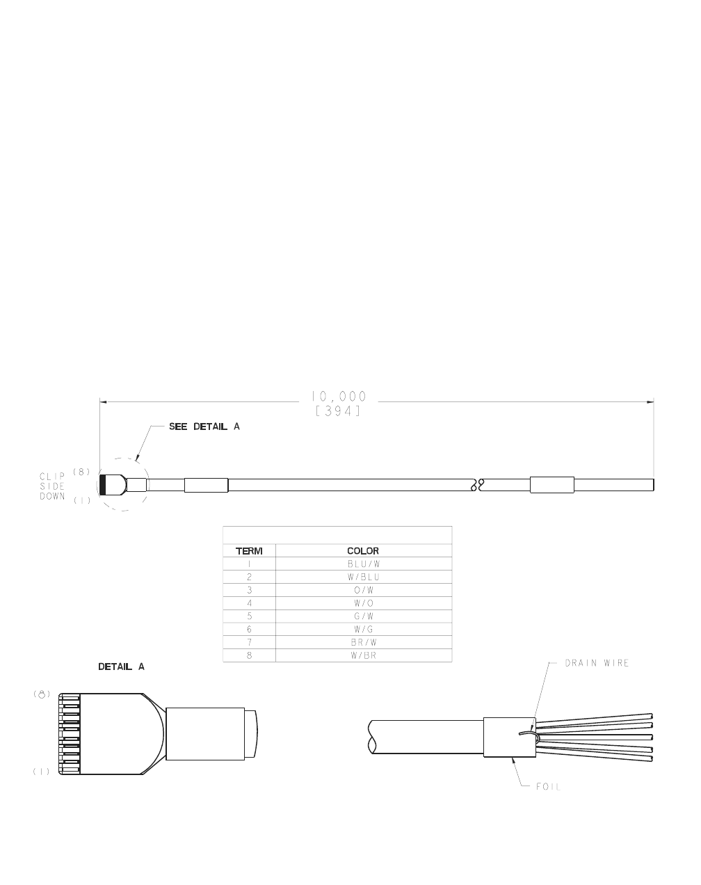
1Refer to the figure below for an illustration of the dual band cabinet
integrated power alarm cable
WIRE COLOR CODES
3-50 Lucent Technologies – Proprietary
See notice on first page 401-703-454
FOA Draft Issue 1
January, 2006
...........................................................................................................................................................................................................................................................
Cable connections in the Modular Cell 4.0B cabinets
................................................................................................................................
............................................
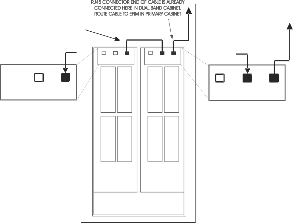
2Locate the integrated power alarm cable in the dual band cabinet. It is
shipped already connected as shown in the figure below. If not, connect
it as shown.
1 2
3 4
1 2
3 4
Primary
Rectifier
Shelf
Auxiliary
Rectifier
Shelf
CIRCUIT BREAKERS
Controller
BATT GROWTH ALARM
GROWTH ALARM
DUAL BAND
CABINET
Controller
THIS CABLE WAS PREVIOUSLY
INSTALLED WITH THE AUXILIARY
RECTIFIER SHELF, IF PRESENT
Cable connections in the Modular Cell 4.0B cabinets
3- 51
Lucent Technologies – Proprietary
See notice on first page
401-703-454
FOA Draft Issue 1
January, 2006
............................................................................................................................................................................................................................................................
................................................................................................................................
............................................
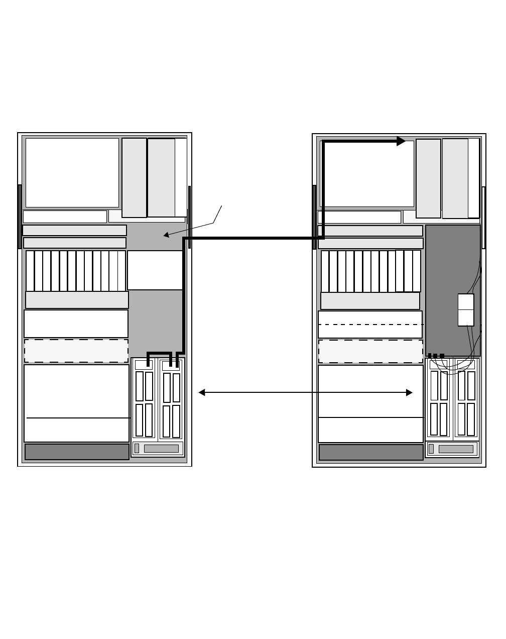
3Route the cable to the EFIT location in the primary cabinet as shown in
the following figure. Using wire ties, secure the cables in both cabinets
in such a way that they do not interfere with removal / replacement of
components, and front door closure.
MODULAR CELL 4.0B DUAL BAND CABINET
DUAL BAND
INTEGRATED POWER-
ALARM CABLE
FAN UNIT
HPDA
A6
FILTERS
HPDA
EFIT
HPDA
FAN UNIT
MODULAR CELL 4.0B PRIMARY CABINET
FILTERS
EFIT
HPDA
THE
BATTERY MODULE WILL
NOT BE PRESENT IN 4.0B
DUAL BAND
CABINETS WITH
MORE THAN SEVEN
CARRIERS
RECTIFIER UNITS AND
ACPDA
3-52 Lucent Technologies – Proprietary
See notice on first page 401-703-454
FOA Draft Issue 1
January, 2006
...........................................................................................................................................................................................................................................................
Cable connections in the Modular Cell 4.0B cabinets
................................................................................................................................
............................................
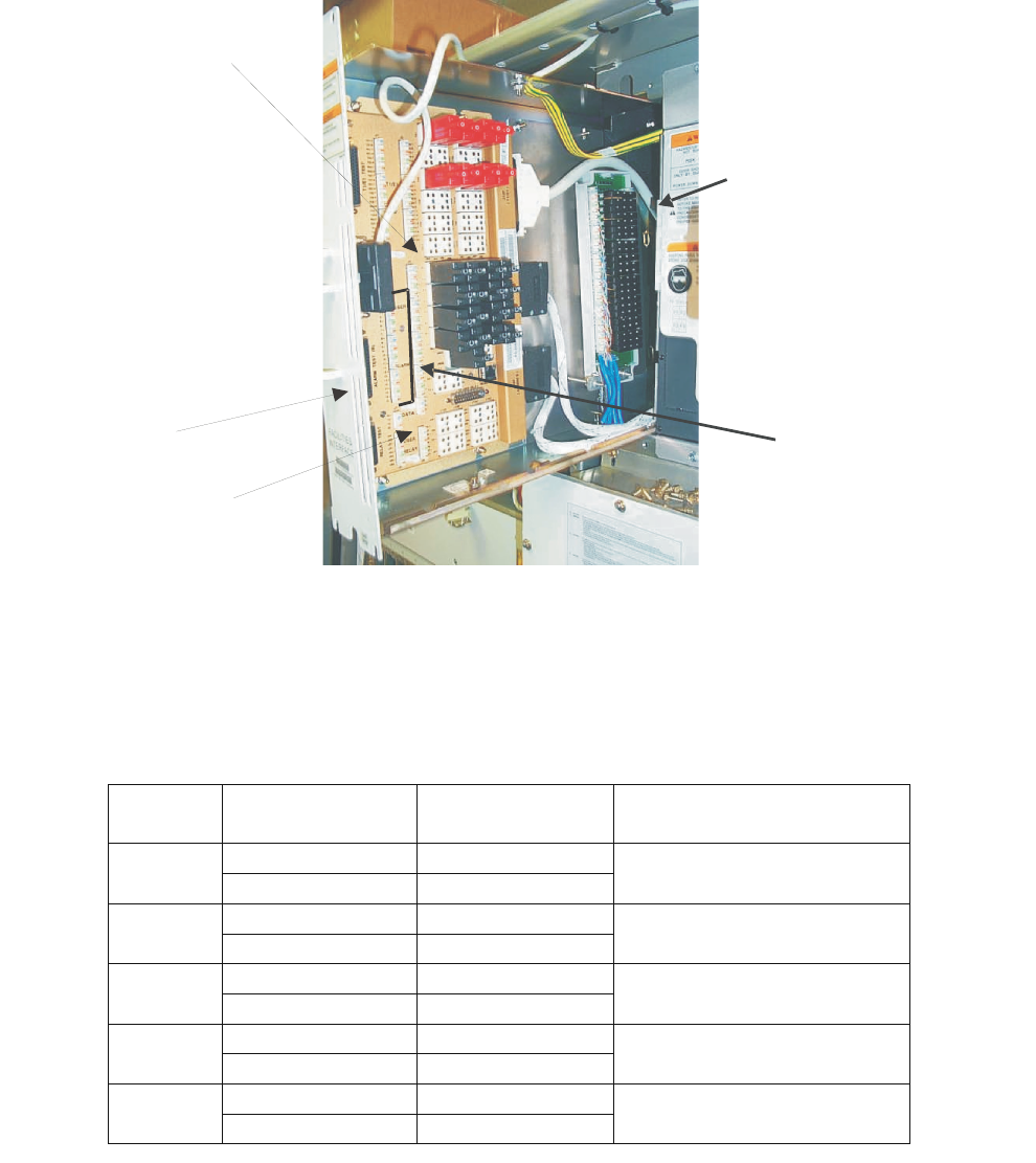
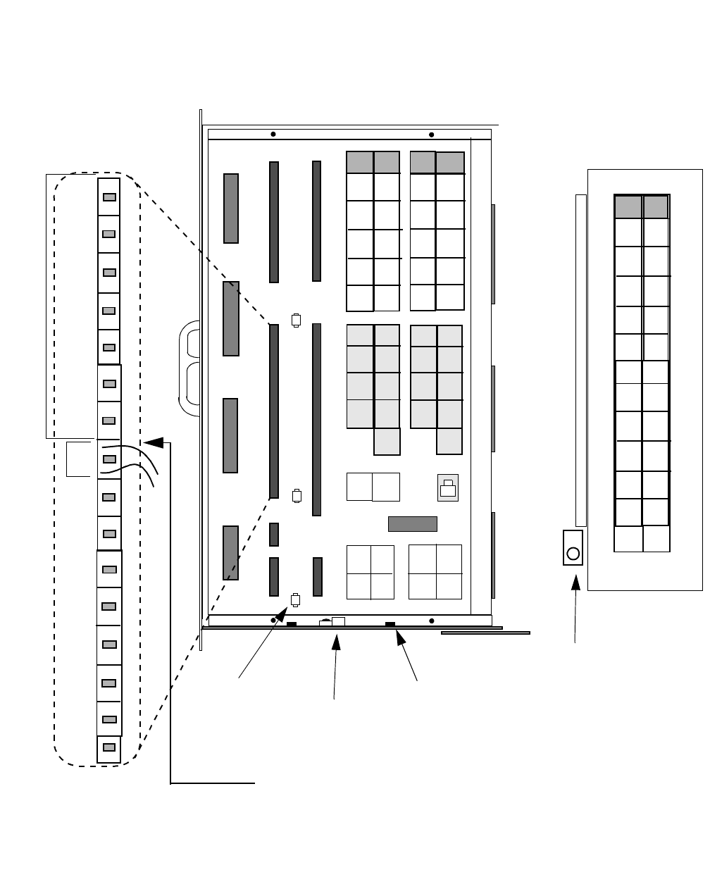
4Route the cable into the EFIT and to J3 on the EFIM in the primary
cabinet as shown in the figure below.
................................................................................................................................
............................................
5Connect the dual band cabinet integrated power alarm wire pairs to J3
as shown in the following table. Refer to the figure on Page 3-53, Note
1, and the table on Page 3 - 54.
POD B (4.0B With URCIIs
Only)
EFIM
EFIT
USER AND POWER
ALARM PUNCHDOWNS
USER AND POWER
ALARM PROTECTORS
Alarm Terminal Block
Pair (J3) Wire Color Function
0+
B
lue - White User 0
Alarm 0- White - Blue Power Major (PMJ)
1+
O
range - White User 1
Alarm
1- White -
Orange Power Minor (PMN)
2+ Green - White User 2
Alarm
2- White - Green AC Fail (ACF)
3+
N
/A User 3
Alarm 3- N/A
NOT USED
4+ Brown - White User 4
Alarm
4- White - Brown
B
atteries on Discharge
(BD)
Cable connections in the Modular Cell 4.0B cabinets
3- 53
Lucent Technologies – Proprietary
See notice on first page
401-703-454
FOA Draft Issue 1
January, 2006
............................................................................................................................................................................................................................................................
The figure below and the following table provides external user alarm
and dual band cabinet integrated power alarm connections to the EFIM
terminal blocks in the Modular Cell 4.0B primary cabinet only.
J1
J4
J3
J5
GROUND
CLAMP
• All punchdown
connections will
accept 24 AWG solid
wires.
J6
J7
J2
CABLE
TIE_DOWN
POINT
(1 of 3)
TX7
TX12
TX1
TX6
0+
15-
33-
16+
J8A J8B J8C J8D
J9A J9B J9C J9D
J10A J10B J10C J10D
TX1
TX7
TX3
TX9
TX5
TX11
TX2
TX8
TX4
TX10
TX6
TX12
RX1 RX2
RX7 RX8
RX3 RX4
RX9 RX10
RX5 RX6
RX11 RX12
0+
0-
1+
1-
2+
2-
3+
3-
4+
4-
5+
5-
6-
6+
7+
7-
8+
8-
9+
9-
10+
10-
11+
11-
12+
12-
13+
13-
14+
14-
15+
15-
0+
2+
4+
6+
8+
10+
12+
14+
16+
18+
20+
22+
24+
26+
28+
30+
32+
UR1
UR2
UR3
UR4
UR5
UR0 UR6
UR7
CABLE
TIE-DOWN
POINT
(1 of 2)
EXTERNAL USER ALARMS
START AT PUNCHDOWN PAIR 7
ON J3, AND CONTINUE ON J4
AFTER PAIR 15.
U
S
E
D
F
O
R
D
U
A
L
B
A
N
D
C
A
B
I
N
E
T
P
O
W
E
R
A
L
A
R
M
S
1+
3+
5+
7+
9+
11+
13+
17+
19+
21+
23+
25+
27+
29+
31+
33+
0-
to
33-
15+
J3
JXA JXB
TX13
TX14
TX15
TX16
TX17
TX18
RX13
RX14
RX15
RX16
RX17
RX18
TX19
TX20
TX21
TX22
TX23
TX24
RX19
RX20
RX21
RX22
RX23
RX24
POD B:
Not present on all
4.0B EFIMs
GROUND CLAMP
(4.0B with PODB)
NOTE 2
EXTERNAL USER ALARM
CONNECTIONS
NOTE 1
DUAL BAND CABINET
POWERALARM
CONNECTIONS

3-54 Lucent Technologies – Proprietary
See notice on first page 401-703-454
FOA Draft Issue 1
January, 2006
...........................................................................................................................................................................................................................................................
Cable connections in the Modular Cell 4.0B cabinets
USER ALARM TABLE
Alarm # Wire Color "J" Conn. Terminal Block Pair Block C/C Protector
USER ALARMS 0 THROUGH 6 UTILIZED FOR INTERNAL POWER ALARMS
User 0
Alarm
If installing a
primary cabinet
without
integrated
power,
refer to
Appendix B for
alarm
conn
ections.
from a customer
supplied power
source
J3 + 0 (Top) Blue J9A (0 / 1)
- 0 (Bottom)
User 1
Alarm
J3 + 1 (Top) Orange
- 1 (Bottom)
User 2
Alarm
J3 + 2 (Top) Green J9A (2 / 3)
- 2 (Bottom)
User 3
Alarm
J3 + 3 (Top) Brown
- 3 (Bottom)
User 4
Alarm
J3 + 4 (Top) Blue J9A (4 / 5)
- 4 (Bottom)
User 5
Alarm
J3 + 5 (Top) Orange
- 5 (Bottom)
User 6
Alarm
J3 + 6 (Top) Green
J9A (6 / 7)
Shared
- 6 (Bottom)
START EXTERNAL USER ALARM PUNCHDOWNS HERE
User 7
Alarm
White-Blue J3 + 7 (Top) Brown J9A (6 / 7)
Shared
Blue-White - 7 (Bottom)
User 8
Alarm
White-Orange J3 + 8 (Top)
Blue
J9B (8 / 9)
Orange-White - 8 (Bottom)
User 9
Alarm
White-Green J3 + 9 (Top) Orange
Green-White - 9 (Bottom)
User 10
Alarm
White-Brown J3 + 10 (Top) Green J9B (10 / 11)
Brown-White - 10 (Bottom)
User 11
Alarm
White-Slate J3 + 11 (Top) Brown
Slate-White - 11 (Bottom)
User 12
Alarm
Red-Blue J3 + 12 (Top)
Blue
J9B (12 / 13)
Blue-Red - 12 (Bottom)
User 13
Alarm
Red-Orange J3 + 13 (Top) Orange
Orange-Red - 13 (Bottom)
User 14
Alarm
Red-Green J3 + 14 (Top) Green J9B (14 / 15)
Green-Red - 14 (Bottom)
User 15
Alarm
Red-Brown J3 + 15 (Top) Brown
Brown-Red - 15 (Bottom)

Cable connections in the Modular Cell 4.0B cabinets
3- 55
Lucent Technologies – Proprietary
See notice on first page
401-703-454
FOA Draft Issue 1
January, 2006
............................................................................................................................................................................................................................................................
User 16
Alarm
Red-Slate J4
+
16 (Top)
Blue
J9C (16 / 17)
Slate-Red - 16 (Bottom)
User 17
Alarm
Black-Blue J4 + 17 (Top) Orange
Blue-Black - 17 (Bottom)
User 18
Alarm
Black-Orange J4 + 18 (Top) Green J9C (18 / 19)
Orange-Black - 18 (Bottom)
User 19
Alarm
Black-Green J4 + 19 (Top) Brown
Green-Black - 19 (Bottom)
User 20
Alarm
Black-Brown J4 + 20 (Top)
Blue
J9C (20 / 21)
Brown-Black - 20 (Bottom)
User 21
Alarm
Black-Slate J4 + 21 (Top) Orange
Slate-Black - 21 (Bottom)
User 22
Alarm
Yellow-Blue J4 + 22 (Top) Green J9C (22 / 23)
Blue-Yellow - 22 (Bottom)
User 23
Alarm
Yellow-Orange J4 + 23 (Top) Brown
Orange-Yellow - 23 (Bottom)
User 24
Alarm
Yellow-Green J4 + 24 (Top)
Blue
J9D(24 / 25)
Green-Yellow - 24 (Bottom)
User 25
Alarm
Yellow-Brown J4 + 25 (Top) Orange
Brown-Yellow - 25 (Bottom)
User 26
Alarm
Yellow-Slate J4 + 26 (Top) Green J9D (26 / 27)
Slate-Yellow - 26 (Bottom)
User 27
Alarm
Violet-Blue J4 + 27 (Top) Brown
Blue-Violet - 27 (Bottom)
User 28
Alarm
Violet-Orange J4 + 28 (Top) Blue J9D(28 / 29)
Orange-Violet - 28 (Bottom)
User 29
Alarm
Violet-Green J4 + 29 (Top) Orange
Green-Violet - 29 (Bottom)
User 30
Alarm
Violet-Brown J4 + 30 (Top) Green J9D (30 / 31)
Brown-Violet - 30 (Bottom)
User 31
Alarm
White-Blue* J4 + 31 (Top) Brown
Blue-White* - 31 (Bottom)
User 32
Alarm
White-Orange* J4 + 32 (Top)
Blue
J9D (32 / 33)
Orange-White* - 32 (Bottom)
User 33
Alarm
White-Green* J4 + 33 (Top)
Orange
Green-White* - 33 (Bottom)
Table note * A second cable is required
3-56 Lucent Technologies – Proprietary
See notice on first page 401-703-454
FOA Draft Issue 1
January, 2006
...........................................................................................................................................................................................................................................................
Cable connections in the Modular Cell 4.0B cabinets

4- 1
Lucent Technologies – Proprietary
See notice on first page
401-703-454
FOA Draft Issue 1
January, 2006
............................................................................................................................................................................................................................................................
4 Power and power alarm
connections in Modular Cell
4.0B cabinets with integrated
power
.............................................................................................................................................................................................................................................................
Overview
Purpose The purpose of this chapter is to provide power and power alarm cable
installation instructions for 4.0B primary and dual band cabinets with
integrated power, as well as for power and alarm connections from
battery cabinets connected to them. Also provided are power references
for cabinets without integrated power
This chapter contains the following sections.
Modular Cell 4.0B cabinets without integrated power that
utilize non-Lucent power (reference)
4 - 2
Power and alarm wiring overview 4 - 3
Safety precautions 4 - 5
How to route and connect the AC utility wires at a Modular Cell
4.0B primary or dual band cabinet
4 - 6
How to make the cable connections between the first WNG
battery cabinet and the 4.0B primary cabinet
4 - 14
How to make the cable connections between the second WNG
battery cabinet and the first WNG battery cabinet
4 - 44
How to install 60ECv2 battery cabinets with a 4.0B primary
cabinet with integrated power (reference)
4 - 71

4-2 Lucent Technologies – Proprietary
See notice on first page 401-703-454
FOA Draft Issue 1
January, 2006
...........................................................................................................................................................................................................................................................
Power and power alarm connections in Modular Cell 4.0B
cabinets with integrated power
Modular Cell 4.0B cabinets without
integrated power that utilize non-
Lucent power (reference)
.............................................................................................................................................................................................................................................................
Overview
Objectives To provide non-Lucent customer supplied power connection references
.............................................................................................................................................................................................................................................................
Non-Lucent power references
References Important! If installing a Modular Cell 4.0B cabinet with
integrated power, proceed to Power and alarm wiring overview on
Page 4 - 3. If installing a Modular Cell 4.0B cabinet without
integrated power, that utilizes non-Lucent customer supplied
power, proceed as below:
For DC power and power system alarm requirements, refer to
Appendix B of the following document.
•Flexent Modular Cell 4.0/4.0B Outdoor Site Preparation
Guidelines, 401-703-413
If the requirements listed in the applicable document have been met,
refer to the applicable vendor documentation, and skip to the following
appendix to continue the installation:
Appendix B of this document for installation the ancillary hardware,
and the routing and connection of DC, AC and alarm cables from a
non-Lucent power source to an outdoor Modular Cell 4.0B cabinet.
After completion of Appendix B, return to:
• Chapter 6 if installing a 4.0B dual band cabinet
• Chapter 7 to finish the installation.
Power and power alarm connections in Modular Cell 4.0B
cabinets with integrated power
4- 3
Lucent Technologies – Proprietary
See notice on first page
401-703-454
FOA Draft Issue 1
January, 2006
............................................................................................................................................................................................................................................................
Power and alarm wiring overview
..............................................................................................................................................................................................................................................................................
Overview
Purpose The purpose of the section is to provide illustrations of the cables routed and
connected in this chapter. Instructions are provided for AC wire routing to 4.0B
primary and dual band cabinets.
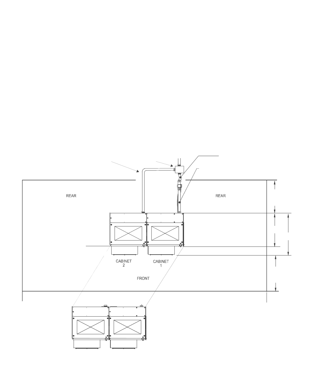
AC conduits A junction box installed near the primary / dual band line-up will provide
individual feeds to both the primary and dual band cabinet, while requiring
only one feed from the main panel. Refer to the figure below and the figure on
Page 4 - 4.
J
unc
ti
on
b
ox
for AC power to
4.0B dual band
cabinet
2” conduit assembly
for AC power to
4.0B dual band
cabinet
CABINET
1
CABINET
2
EXAMPLE 1:
CABINET 1 = 850 Primary
CABINET 2 = PCS Dual Band
EXAMPLE 2:
CABINET 1 = PCS Primary
CABINET 2 = 850 Dual Band
2” conduit assembly for
AC power (TYP) in lower
position
2” conduit assembly for
T1/E1 and User Alarms
(TYP) in upperposition
914.4 (36.0) Min.
for service access
900.3 (35.44) Min.
for service access
813
(32.0)
1016
(72.0)
4-4 Lucent Technologies – Proprietary
See notice on first page 401-703-454
FOA Draft Issue 1
January, 2006
...........................................................................................................................................................................................................................................................
Power and power alarm connections in Modular Cell 4.0B
cabinets with integrated power
Power and alarm wiring for
integrated power 4.0B
primary and dual band
cabinets with battery
cabinets and frames
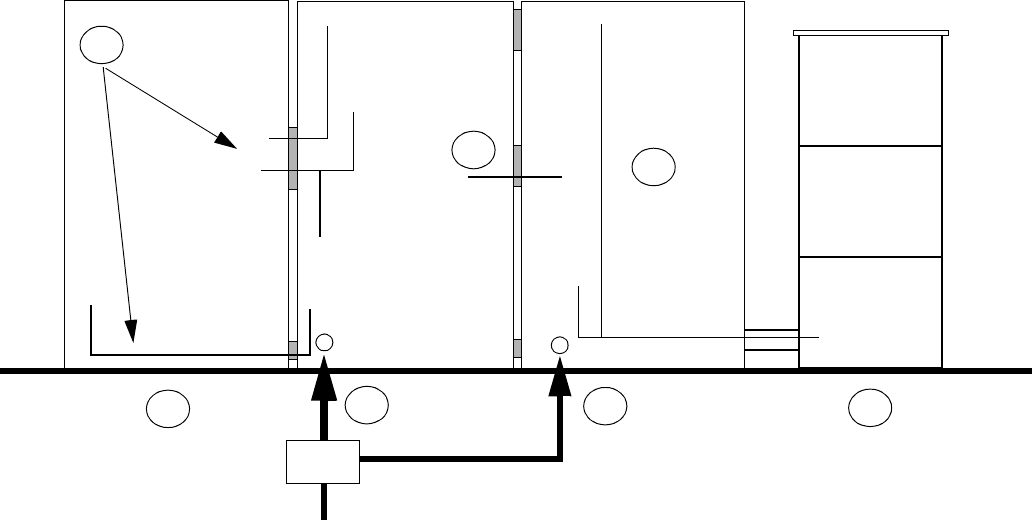
This module provides a key list and an illustration of the AC utility
connections, as well as the internal AC and DC power and power alarm
wiring at a Modular Cell 4.0B site that has examples of both WNG
battery cabinets and EZBFo battery frames. WNG battery cabinets
support 4.0B primary cabinets only. Refer to the key and figure below.
1. AC utility connection to the primary cabinet
2. First WNG battery cabinet (a second battery cabinet can be
connected)
3. AC, DC, alarm and fan power / alarm cable connections from the
first battery cabinet to the primary cabinet
4. RF connections between the primary cabinet and growth/DB*
cabinet (refer to Chapter 6)
5. AC utility connection to the dual band cabinet (via a junction box)
6. EZBFo battery frame (a second battery frame can be connected).
Refer to Appendix A for installation instructions.
7. AC, DC, alarm and fan power / alarm cable connections from the
first battery frame to the dual band cabinet
MODULAR
CELL 4.0B
PRIMARY CABINET
FIRST
WNG24-BC
BATTERY CABINET
MODULAR
CELL 4.0B
DUAL BAND CABINET
SECOND
WNG24-BC
BATTERY
CABINET
3
6
1
AC
AC
DC
4
REAR VIEW
ALARMS AND
FAN POWER/
ALARM.
5
ADD-ON
BATTERY
MODULE #2 *
(3rd Module)
ADD-ON
BATTERY
MODULE #1
(2nd Module)
EZBFo BATTERY
FRAME #1
(REFER TO
APPENDIX A)
BATTERY
BASE
MODULE #1
DC,
ALARMS,
AND FAN
POWER/
ALARM.
7
2
* If installed in seismic zone 4, a second add-on module requires a Zone 4 kit for installation
AC

Power and power alarm connections in Modular Cell 4.0B
cabinets with integrated power
4- 5
Lucent Technologies – Proprietary
See notice on first page
401-703-454
FOA Draft Issue 1
January, 2006
............................................................................................................................................................................................................................................................
.............................................................................................................................................................................................................................................................
Safety precautions
The following safety precautions should be read and understood before
starting the installation of power cables.
CAUTION
Damage to equipment
The battery cables in the primary cabinet must not be
connected until after the AC utility wires are connected and
AC power is turned on at the main panel. Do not connect the
battery cables until instructed to do so in Chapter 7,
"Finishing the installation."
WARNING
Electrical Shock Hazard
Failure to follow the order of the installation procedure (as
written) can result in an energized AC or DC circuit, which
creates an electrical shock hazard.
Follow these rules:
1. Do not connect AC power until instructed to do so.
2. When making AC connections at the primary or dual
band cabinets, make sure that AC power is turned off at
the main panel.
3. When installing battery cabinets, do not connect any
DC cables, until instructed to do so.
4. Observe and strictly follow all additional safety
precautions.
5. When completing electrical connections, always use
tools that are properly insulated.
6. Depending upon local regulations, AC utility power
connections to the Modular Cell 4.0B primary and dual
band cabinet may be performed by a licensed
electrician.

4-6 Lucent Technologies – Proprietary
See notice on first page 401-703-454
FOA Draft Issue 1
January, 2006
...........................................................................................................................................................................................................................................................
Power and power alarm connections in Modular Cell 4.0B
cabinets with integrated power
How to route and connect the AC
utility wires at a Modular Cell 4.0B
primary or dual band cabinet
.............................................................................................................................................................................................................................................................
Overview
Purpose This section contains instructions for routing and connection of the AC
utility wires at a Modular Cell 4.0B primary or dual band cabinet.
.............................................................................................................................................................................................................................................................
Route and connect the AC utility wires
Overview This section contains the following procedures.
Prepare the AC power module (ACPDA) for connection of the
AC utility wires
4 - 7
Install a 2-inch flexible conduit fitting on the primary or dual
band cabinet
4 - 9
Connect the flexible conduit between the existing metal
conduit and the fitting at the primary or dual band cabinet
4 - 10
Route and connect the AC utility wires in the primary or dual
band cabinet
4 - 12