Alcatel Lucent USA ONEBTS-11 UMTS-CDMA Transceiver System (850) User Manual 401703454i1
Alcatel-Lucent USA Inc. UMTS-CDMA Transceiver System (850) 401703454i1
Contents
users manual m

B- 41
Lucent Technologies – Proprietary
See notice on first page
401-703-454
FOA Draft Issue 1
January, 2006
............................................................................................................................................................................................................................................................
Description of the AC
power cables The installation requires the following AC power cable or cables.
• #10 AWG 3-wire - for the heaters
• #14 AWG 3-wire - for the convenience outlet, if applicable (not
present in international cabinets)
DANGER
Electrical Shock Hazard
Installation of the Modular Cell 4.0B cabinets require
connections to be made that require AC power to be turned off
at specific circuit breakers in the non-Lucent power source.
Failure to follow instructions to turn off these breakers can
create an electrical shock hazard. Failure to follow the order
of the installation procedure (as written) can also create an
electrical shock hazard. The procedures in this manual do not
include safety procedures regarding working on energized
equipment. When this manual is used to install equipment in
an energized system, the appropriate safety procedures must
be followed in addition to the procedures in this manual.
Follow these rules:
1. Perform installation steps in the order provided.
2. Observe and strictly follow all safety precautions.
3. When completing electrical connections, always use
tools that are properly insulated.
B- 42 Lucent Technologies – Proprietary
See notice on first page 401-703-454
FOA Draft Issue 1
January, 2006
...........................................................................................................................................................................................................................................................
Route the AC power cables
to the Modular Cell 4.0B
primary cabinet
Important! If installing a 4.0B dual band cabinet, skip to Cable
pre-installation instructions for the dual band cabinet on Page B - 50 to
continue the installation.
Use the following procedure to route the AC power cable or cables.
................................................................................................................................
............................................
1At the non-Lucent power source, set the AC circuit breaker(s) to the off
position and locate the AC power cable or cables. There will be a heater
cable (and a convenience outlet cable, if applicable).
................................................................................................................................
............................................
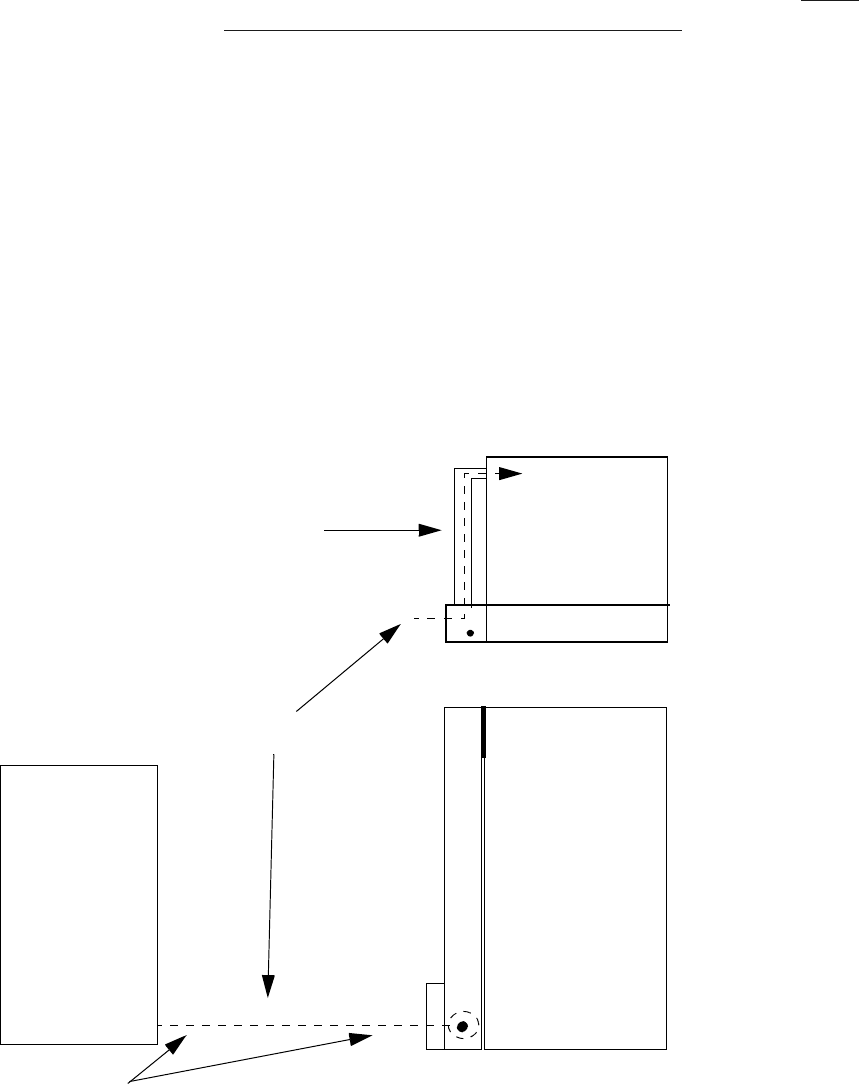
2Route the AC power cables (1 or 2) through the AC conduit (if
applicable) and into the cable duct. Refer to the figure below
MODULAR
CELL 4.0B
PRIMARY
CABINET
AC CABLE
NON-LUCENT
POWER
SOURCE
TOP VIEW
AC CONDUIT
REAR VIEW
If flush mounting is not possible, the bottom (2-inch) conduit (example) is used for
routing of cables from the non-Lucent power source to the cable duct.
B- 43
Lucent Technologies – Proprietary
See notice on first page
401-703-454
FOA Draft Issue 1
January, 2006
............................................................................................................................................................................................................................................................
................................................................................................................................
............................................
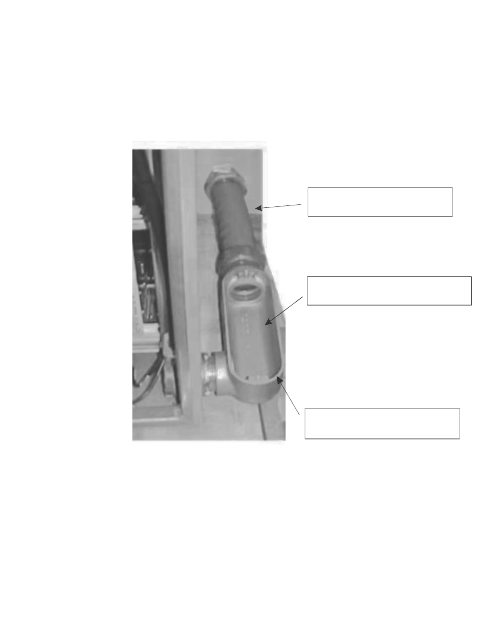
3Pull the cable or cables through the AC conduit at the front of the cable
duct, through the 90 degree conduit body, and into the bottom of the
Modular Cell 4.0B primary cabinet. Refer to the figure below.
................................................................................................................................
............................................
4Replace the gasket and cover on the 90-degree conduit body. Refer to
the figure below.
1. Route AC cable from cable
duct to 90-degree conduit body
3. Replace gasket and cover on
90 degree conduit body
2. Route AC cable from 90-degree
conduit body into primary cabinet

B- 44 Lucent Technologies – Proprietary
See notice on first page 401-703-454
FOA Draft Issue 1
January, 2006
...........................................................................................................................................................................................................................................................
How to route and connect the AC power cables at the Modular Cell
.............................................................................................................................................................................................................................................................
4.0B primary cabinet
Overview Important! If installing a 4.0B dual band cabinet, skip to Cable pre-
installation instructions for the dual band cabinet on Page B - 50 to
continue the installation.
This procedure module provides instructions for the routing and
connection of the AC power cable or cables at the primary cabinet.
Step-by-step instructions are provided for the following tasks.
Connect the AC power cable for the heaters in the primary
cabinet
B - 46
Connect the AC power cable for the convenience outlet in the
primary cabinet (NAR only)
B - 48
B- 45
Lucent Technologies – Proprietary
See notice on first page
401-703-454
FOA Draft Issue 1
January, 2006
............................................................................................................................................................................................................................................................
Location of the AC junction
box and the convenience
outlet
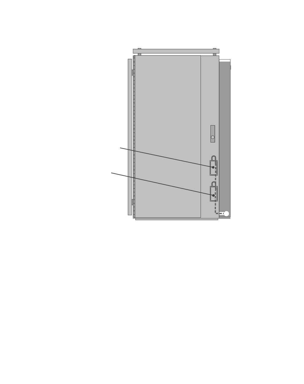
Refer to the figure below for the location of the AC heater junction box
in the primary cabinet (as well as the convenience outlet, if applicable).
Description of the AC
power cables The installation requires the following AC power cable or cables.
• #10 AWG 3-wire - for the heaters
• #14 AWG 3-wire - for the convenience outlet, if applicable (not
present in international cabinets).
FRONT VIEW
Modular Cell Primary 4.0B Primary Cabinet
Without Integrated Power
Heater
AC Junction Box
C
onvenience Outlet
(if applicable)
B- 46 Lucent Technologies – Proprietary
See notice on first page 401-703-454
FOA Draft Issue 1
January, 2006
...........................................................................................................................................................................................................................................................
Connect the AC power
cable for the heaters in the
primary cabinet
Use the following procedure to connect the AC power cable for the
heaters. Refer to the figure on Page B - 45 for the location of the heater
junction box. Refer to the figure on Page B - 47 for connections.
................................................................................................................................
............................................
1At the non-Lucent power source, set the AC circuit breaker(s) to the off
position.
................................................................................................................................
............................................
2Identify the correct cable for the heaters. This is the larger of the two
cables (10 AWG), with three wires colored black (L1), red (L2) and
green with a yellow stripe (GND).
Important! Alternately, a three-wire cable with the following
color code may also be used: brown (L1), blue (L2) and green
with a yellow stripe (Ground).
................................................................................................................................
............................................
3Allow adequate slack and cut this power cable to the correct length.
................................................................................................................................
............................................
4Strip the insulation off of the cable to expose the individual wires and
then strip the insulation off of the ends of the individual wires.
................................................................................................................................
............................................
5Loosen the three terminal block screws. Refer to the figure on Page B -
47.
B- 47
Lucent Technologies – Proprietary
See notice on first page
401-703-454
FOA Draft Issue 1
January, 2006
............................................................................................................................................................................................................................................................
................................................................................................................................
............................................
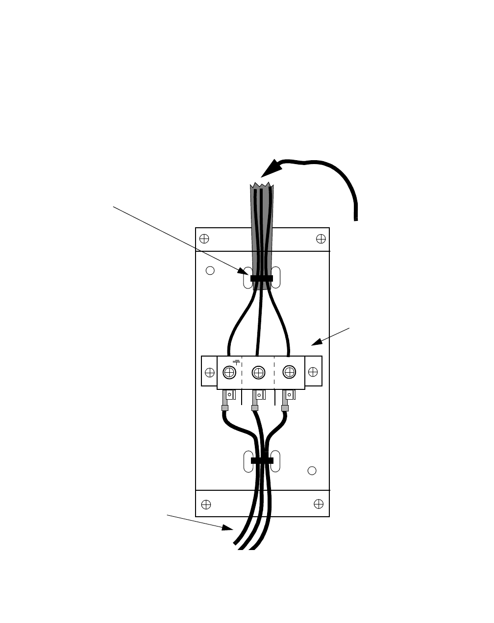
6Connect each labeled/colored wire to the AC junction box terminal
block as shown in the figure below.
• Black/Brown to L1
• Red/Blue to L2
• Green/Yellow to ground (symbol).
................................................................................................................................
............................................
7Install and tighten a wire tie as shown in the figure above. Then install
the AC junction box cover.
1L
2L
GND L1
L2
WIRE
TIE
FROM
POWER
SOURCE
TERMINAL BLOCK
TO HEATER
HEATER AC
JUNCTION BOX IN
PRIMARY CABINET
MODULAR CELL 4.0B PRIMARY CABINET: DETAIL VIEW
B- 48 Lucent Technologies – Proprietary
See notice on first page 401-703-454
FOA Draft Issue 1
January, 2006
...........................................................................................................................................................................................................................................................
Connect the AC power
cable for the convenience
outlet in the primary
cabinet (NAR only)
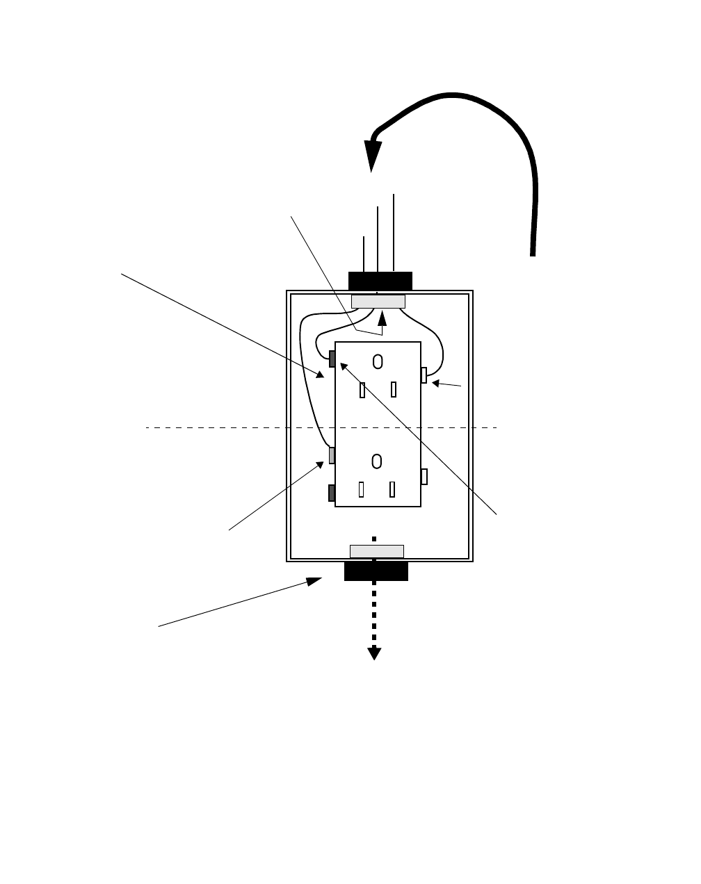
Use the following procedure to connect the AC power cable for the
convenience outlet. Refer to the figure on Page B - 45 for the location
of the convenience outlet. Refer to the figure on Page B - 49 for
connections.
................................................................................................................................
............................................
1At the non-Lucent power source, set the AC circuit breaker(s) to the off
position.
................................................................................................................................
............................................
2Identify the correct cable for the convenience outlet. This is the smaller
of the two cables (14 AWG), with three wires colored black (L), white
(N) and green with a yellow stripe (GND).
................................................................................................................................
............................................
3Prepare the end of this power cable.
1. Allow adequate slack and cut off the cable to the correct length.
2. Strip the insulation off of the cable to expose the individual wires.
3. Strip the insulation off of the ends of the individual wires.
................................................................................................................................
............................................
4Remove the knock-out, if required. Refer to the figure on Page B - 49.
................................................................................................................................
............................................
5Route the cable through the liquid-tight connector into the junction box
and tighten the connector.
Important! When performing the next step, the location of the
screws may vary depending upon the vendor. Make sure that the
wires are connected to the "Line" side of the outlet.
................................................................................................................................
............................................
6Connect the L and N wires to the correct screw terminal on the Line side
of the supplied outlet and the GND wire to the green ground screw as
follows. Refer to the figure on Page B - 49.
• Black wire (L) to brass screw
• White wire (N) to silver screw
• Green-yellow striped wire (GND) to green screw
B- 49
Lucent Technologies – Proprietary
See notice on first page
401-703-454
FOA Draft Issue 1
January, 2006
............................................................................................................................................................................................................................................................
................................................................................................................................
............................................
7Install the outlet into the junction box.
................................................................................................................................
............................................
8Install the AC junction box cover.
................................................................................................................................
............................................
9Return to Chapter 7 to finish the installation.
L
G
N
TO MODULAR CELL
4.0B DUAL BAND
CABINET
* SCREW LOCATION MAY VARY BY OUTLET VENDOR
LIQUID-TIGHT
CONNECTOR (1
of 2)
LOAD
SIDE
LINE
SIDE
GREEN
SCREW*
BRASS
SCREW*
SILVER
SCREW*
FROM POWER
SOURCE
OUTLET
KNOCK-OUT
LOCATION
CONVENIENCE
OUTLET IN
PRIMARY
CABINET
MODULAR CELL 4.0B PRIMARY CABINET: DETAIL VIEW
B- 50 Lucent Technologies – Proprietary
See notice on first page 401-703-454
FOA Draft Issue 1
January, 2006
...........................................................................................................................................................................................................................................................
.............................................................................................................................................................................................................................................................
Cable pre-installation instructions for the dual band cabinet
Wiring overview Important! If installing a Modular Cell 4.0B primary cabinet, return to
Chapter 7 to finish the installation.
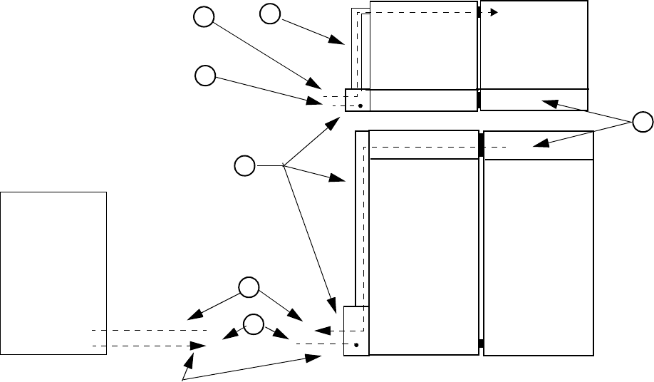
The following is the wiring overview, item number coded to the figure
below.
a. DC load and return wiring (see item 1), is routed from the
antenna cable cover (see item 2) of the Modular Cell dual
band cabinet, through the antenna cable cover of the Modular
Cell primary cabinet, and follows a vertical route down the
cable duct assembly (see item 3), through the top (2-1/2 inch)
opening at the bottom of the cable duct. They are then routed
through the top conduit to the non-Lucent power source.
b. AC wiring from the non-Lucent power source (see item 4) is
routed through the bottom 2-inch conduit through the bottom
2-inch opening in the cable duct (see item 3), forward
through the AC conduit (see item 5), through the opening at
the bottom front of the cabinet, and through the primary
cabinet and into the dual band cabinet.
2
5
1
NON-LUCENT
POWER
SOURCE
MODULAR
CELL 4.0B
PRIMARY
CABINET
REAR
VIEW
TOP VIEW
4
4
If the power source is not flush mounted with zero spacing to the cable duct, a 2-1/2 conduit (item 1) is used for routing of
DC cables between the cable duct. and the non-Lucent power source. Ac is routed through a 2-inch conduit (Item 4)
MODULAR
CELL 4.0B
DUAL BAND
CABINET
REAR
VIEW
3
1
TOP VIEW

B- 51
Lucent Technologies – Proprietary
See notice on first page
401-703-454
FOA Draft Issue 1
January, 2006
............................................................................................................................................................................................................................................................
.............................................................................................................................................................................................................................................................
How to install ancillary hardware for the dual band cabinet DC cables
Overview The non-Lucent power source may have been connected directly to the
cable duct assembly, or alternately, located away from the primary
cabinet with a conduit utilized for cable routing to the cable duct
assembly. Perform one of the following procedures to install the 2-1/2-
inch chase nipple or conduit required for routing of DC cables to the
dual band cabinet.
This section covers the following procedures, as applicable.
Install the 2-1/2-inch chase nipple if the power source is
connected directly to the cable duct
B - 52
Install a 2-1/2-inch conduit if the power source is not connected
directly to the cable duct
B - 53
B- 52 Lucent Technologies – Proprietary
See notice on first page 401-703-454
FOA Draft Issue 1
January, 2006
...........................................................................................................................................................................................................................................................
Install the 2-1/2-inch chase
nipple if the power source
is connected directly to the
cable duct
Important! If conduits were used to attach the non-Lucent
power source to the cable duct, skip to Install a 2-1/2-inch conduit if
the power source is not connected directly to the cable duct on Page B
- 53
Use the following steps to install the chase nipple if the power source is
connected directly to the bottom of the cable duct assembly (zero
spacing).
................................................................................................................................
............................................
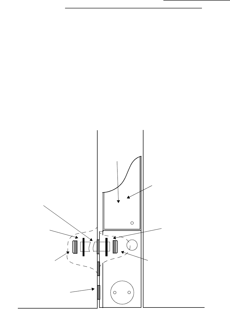
1Install the 2-1/2 chase nipple, lock nuts, and insulating bushing into the
top opening, and hand-tighten. Refer to the figure below.
................................................................................................................................
............................................
2Hold the lock nut inside of the non-Lucent power source with a wrench,
and tighten the lock nut inside of the cable duct with a hammer and a
screwdriver (two technicians needed). Refer to the figure below.
CABLE
DUCT
ASSEMBLY
CABLE
DUCT
COVER
MODULAR
CELL 4.0B
PRIMARY
CABINET
INSULATING
BUSHING
LOCKNUT
FOAM
GASKETS
NON-LUCENT
POWER
SOURCE
LOCKNUT
INSULATING
BUSHING
2-1/2 INCH
CHASE
NIPPLE
B- 53
Lucent Technologies – Proprietary
See notice on first page
401-703-454
FOA Draft Issue 1
January, 2006
............................................................................................................................................................................................................................................................
Install a 2-1/2-inch conduit
if the power source is not
connected directly to the
cable duct
Important! If the non-Lucent power source is attached directly
to the cable duct, skip to How to route and connect DC power cables
to a Modular Cell 4.0B dual band cabinet on Page B - 54.
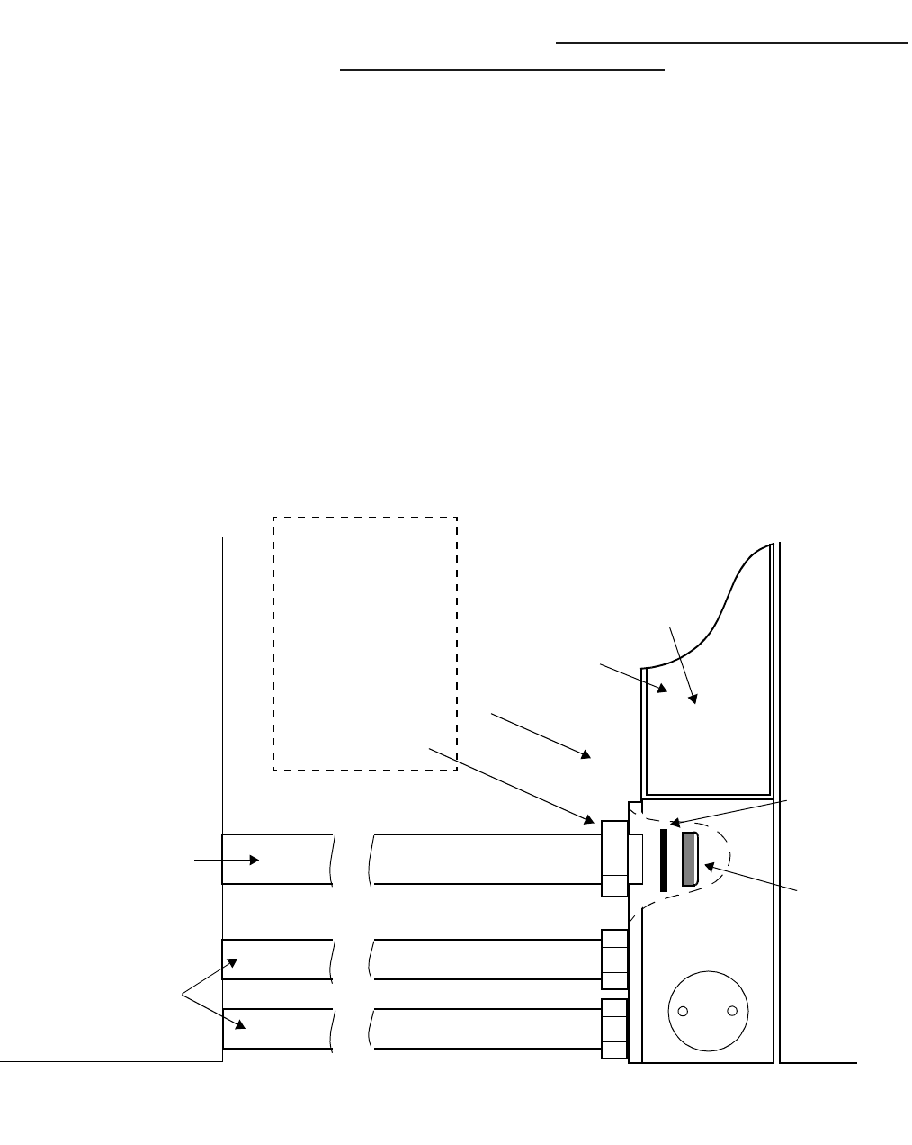
1Remove the cover from the top (2-1/2inch) opening in the cable duct and
install a 2-1/2inch conduit (from the power source) and conduit fitting
at the opening. Refer to the figure below.
................................................................................................................................
............................................
2Thread a locknut and insulating bushing onto the end of the conduit
fitting inside of the cable duct, and hand-tighten. Refer to the figure
below.
................................................................................................................................
............................................
3Hold the fitting with a wrench, and tighten the locknut inside of the
cable duct with a hammer and a screwdriver (two technicians needed).
Refer to the figure below.
CABLE
DUCT
ASSEMBLY
CABLE
DUCT
COVER MODULAR
CELL 4.oB
PRIMARY
CABINET
INSULATING
BUSHING
LOCKNUT
2-1/2 inch
conduit for dual
band DC cables
NON-LUCENT
POWER
SOURCE
LIQUID TIGHT
CONDUIT FITTING
NEEDED IF NON -
LUCENT POWER
CABINET IS NOT
IMMEDIATELY
ADJACENT TO
THE CABLE DUCT
(including locknut
and insulating bush-
ing)
Existing 2-inch
conduits
AC
Primary cabinet DC and
power alarms

B- 54 Lucent Technologies – Proprietary
See notice on first page 401-703-454
FOA Draft Issue 1
January, 2006
...........................................................................................................................................................................................................................................................
How to route and connect DC power cables to a Modular Cell 4.0B
.............................................................................................................................................................................................................................................................
dual band cabinet
Overview Important! If installing a Modular Cell 4.0B primary cabinet, return to
Chapter 7 to finish the installation.
This procedure provides instructions for the installation of the DC
power cables from non-Lucent power source to a 4.0B dual band
cabinet.
If the requirements listed in the applicable document have been met,
refer to the applicable vendor documentation and use this document for
power connections.
Step-by-step instructions are provided for the following tasks.
For DC power requirements, refer to Appendix E of the following
document.
•Flexent Modular Cell 4.0/4.0B Outdoor Site Preparation
Guidelines, 401-703-413
Description of the DC power cables
Modular Cell cabinets without integrated power require DC power
cables, red feed cables (+) and black return cables (-) for attachment
from a separate power source. Note that the terminal lugs for
attachment at the Modular Cell 4.0B dual band cabinet are supplied
with the cabinet.
Label dual band cabinet +24VDC cables B - 57
Label dual band cabinet 24VDC return cables B - 57
Route the DC cables from the dual band cabinet to the non-Lucent
power source
B - 59
Connect the DC cables at Modular Cell 4.0B dual band cabinet B - 62

B- 55
Lucent Technologies – Proprietary
See notice on first page
401-703-454
FOA Draft Issue 1
January, 2006
............................................................................................................................................................................................................................................................
DC feeders and connection
interface Each Modular Cell outdoor cabinet requires three DC feeds as shown in
the table on the next page. One additional DC feed is required if the
Modular Cell is equipped with an A6 amplifier shelf.
Alternate wire gauges may be used for the DC feeders, but shall be sized
to limit the round trip voltage drop between the power system output
terminals and the Modular Cell input terminals to less than one volt (for
+24 VDC systems).
A current level equal to 80% of the circuit breaker current rating
specified shall be used for this calculation. The wire used for the DC
feeders shall be rated for the environmental condition in which it is used
and shall be rated and sized according to the applicable section in the
National Electrical Code or Canadian Electrical Code, Part I (NAR
markets) and IEC 60364, or the local electrical code in effect
(international markets). The circuit breaker shall be type 51 with DC
trip-delay curve characteristics. The DC power terminal block is located
at the top rear of a Modular Cell outdoor cabinet. The tables below
provide the circuit breaker sizes, wire gauges, maximum wire lengths
and lug dimensions for DC feeders #1, #2, #3, and #4 for 4.0B Modular
Cells.

B- 56 Lucent Technologies – Proprietary
See notice on first page 401-703-454
FOA Draft Issue 1
January, 2006
...........................................................................................................................................................................................................................................................
DC cable specifications The following table provides the DC cable specifications for 4.0B
cabinets. The fourth feed is required for the A6 amplifier shelf only.
Table Notes
Note 1: The fourth feed is required for the A6 amplifier shelf only
Note 2: DC wires and lugs must be rated for 90 degrees C. For longer
wire runs, calculate wire size and circuit breaker rating according to the
National Electric Code or canadian Electrical Code, Part I (NAR
markets) and IEC 60364, or local electrical code in effect (International
markets).
DC feeders and connection interface: Modular Cell 4.0B
Modular
Cell 4.0B Feeder 1#, #2, #3, #4 (Note 1) Dimensions for lug on
DC terminal block
Circuit breaker
(AMPS) Wire size (AWG) Max. Length (Feet)
+24 VDC 150 1 (Note 2) 40 5/16 (threaded stud)
11/16 (max. width)

B- 57
Lucent Technologies – Proprietary
See notice on first page
401-703-454
FOA Draft Issue 1
January, 2006
............................................................................................................................................................................................................................................................
Label dual band cabinet
+24VDC cables Label the dual band cabinet +24VDC cables as shown in the table
below. The (number) in parentheses indicates the DC terminal block
position for connection of each cable. A dual band cabinet has DC
terminal block positions numbered 5 through 8 from right to left. Refer
to the figure on Page B - 63.
Label dual band cabinet
24VDC return cables Label the dual band cabinet 24VDC Return cables as shown in the table
below. The (number) in parentheses indicates the DC terminal block
position for connection of each cable. A dual band cabinet has DC
terminal block positions numbered 5 through 8 from right to left. Refer
to the figure on Page B - 63.
If installing: Then label cables:
4.0B Dual Band Cabinet
(L6A required for first growth cabinet with A6 shelf)
•#1 AWG: Label L4 (5)
•#1 AWG: Label L5 (6)
•#1 AWG: Label L6 (7)
•#1 AWG: Label L6A (8)
(for A6 shelf only)
If installing: Then label cables:
4.0B Dual Band Cabinet
(6A required for first growth cabinet with A6 shelf)
•#1 AWG: Label 4 (5)
•#1 AWG: Label 5 (6)
•#1 AWG: Label 6 (7)
•#1 AWG: Label 6A (8)
(for A6 shelf only)

B- 58 Lucent Technologies – Proprietary
See notice on first page 401-703-454
FOA Draft Issue 1
January, 2006
...........................................................................................................................................................................................................................................................
Observe safety
considerations The safest condition for installing and connecting the dual band cabinet
is with the system de-energized. If a dual band cabinet is to be added to
an operating system, the owner/operator of the system must be
consulted. The owner/operator must provide approval as to whether
and when the system will be fully or partially de-energized. The
customer may request that the work be performed while the system is
energized. If so, observe the following caution.
DANGER
Electrical Shock Hazard
Installation of a Modular Cell 4.0B dual band cabinet
requires DC connections to be made in the non-Lucent power
source with AC power on (unless the installation is performed
during a maintenance window that allows AC power to be
turned off at the main panel and the batteries disconnected).
The procedures in this manual do not include safety
procedures regarding working on energized equipment. When
this manual is used to install equipment in an energized
system, the appropriate safety procedures must be followed in
addition to the procedures in this manual. Failure to follow
the order of the installation procedure (as written) can create
an electrical shock hazard.
Follow these rules:
1. Perform installation steps in the order provided.
2. Observe and strictly follow all safety precautions.
3. When completing electrical connections, always use
tools that are properly insulated.
B- 59
Lucent Technologies – Proprietary
See notice on first page
401-703-454
FOA Draft Issue 1
January, 2006
............................................................................................................................................................................................................................................................
Route the DC cables from
the dual band cabinet to
the non-Lucent power
source
Important! In order to make the routing of the DC cables as
easy as possible, it is recommended that they be routed in a
direction from the dual band cabinet to the non-Lucent power
source, prior to connection at either end.
Perform the following steps to route the DC cables from the dual band
cabinet to the non-Lucent power source.
................................................................................................................................
............................................
1Thoroughly tape over the ends of all cables, and start the routing of the
cables from the area of the DC terminal block at the top of the dual band
cabinet.
................................................................................................................................
............................................
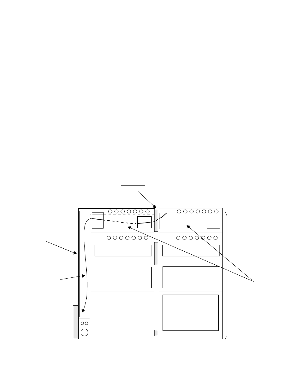
2Route two cables at a time through the middle section of the opening
between the antenna cable covers, and through the antenna cable cover
of the Modular Cell primary cabinet to the cable duct. Refer to the figure
below.
MODULAR
CELL 4.0B
PRIMARY
CABINET
ROUTE THE CABLES THROUGH THE MIDDLE
SECTION OF THE OPENING HERE
MODULAR CELL
4.0B DUAL
BAND
CABINET
CABLE DUCT
ANTENNA
CABLE COVERS
DEC CABLES
B- 60 Lucent Technologies – Proprietary
See notice on first page 401-703-454
FOA Draft Issue 1
January, 2006
...........................................................................................................................................................................................................................................................
................................................................................................................................
............................................
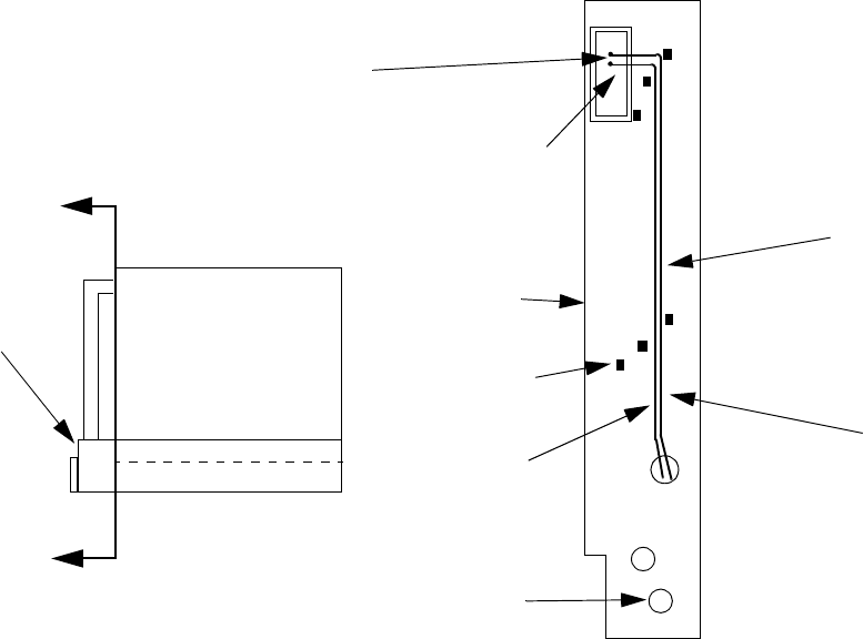
3Route the ends of the DC cables into the cable duct through the middle
section of the opening. Refer to the figure below.
................................................................................................................................
............................................
4Within the cable duct assembly, route the cables downward between the
inner-most cable brackets and the middle cable brackets, as shown in
the figure below. Attach later with wire ties.
A
A
ROUTE CABLES INTO
CABLE DUCT IN THE
MIDDLE SECTION
SHOWN
CABLE DUCT
ASSEMBLY
OPENING IN THE
MODULAR CELL
PRIMARY CABINET
ANTENNA CABLE
COVER
CABLE
BRACKET
(1 of 6) 24-VDC RETURN
CABLES TO THE
MODULAR CELL
4.0B DUAL BAND
CABINET
2-INCH
OPENING
USED FOR AC
CABLES MUST BE
ROUTED IN THIS
LOCATION
(BETWEEN INNER-
MOST AND
CENTER BRACKET
24-VDC PWR
CABLES TO THE
MODULAR CELL
4.0B DUAL BAND
CABINET
Modular Cell
Primary
Cabinet
(Top View)
CABLE DUCT
ASSEMBLY
VIEW A - A
B- 61
Lucent Technologies – Proprietary
See notice on first page
401-703-454
FOA Draft Issue 1
January, 2006
............................................................................................................................................................................................................................................................
................................................................................................................................
............................................
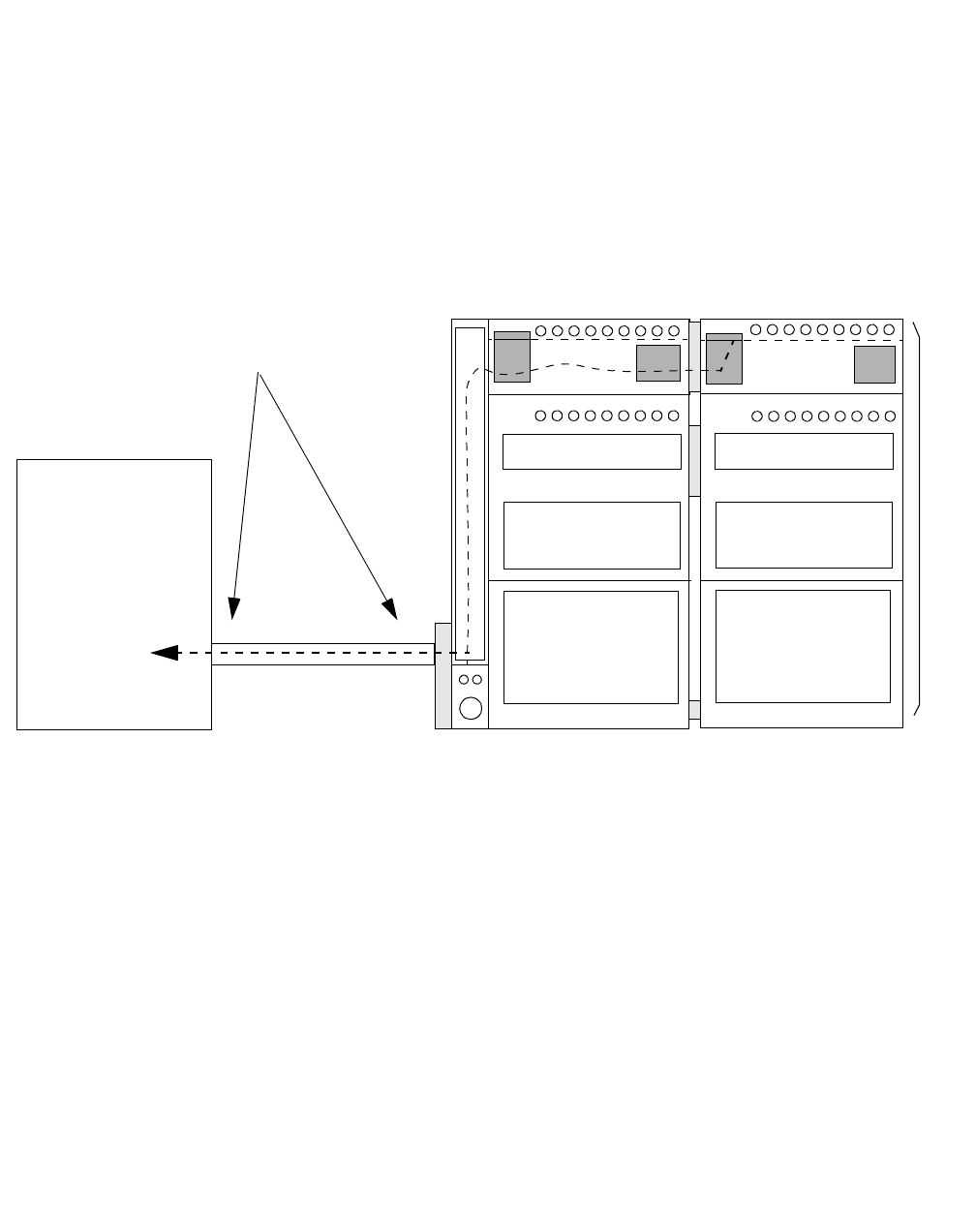
5Route the cables through the top (2-1/2 inch) opening at the bottom of
the cable duct. Refer to the figure below.
................................................................................................................................
............................................
6Route the cables to the non-Lucent power source through the 2-1/2 inch
conduit. Refer to the figure below.
................................................................................................................................
............................................
7If the DC cables need to be shortened before they are attached in the
non-Lucent power source, the labels may be cut off. Remember to re-
label each cable immediately after it is cut.
Important! The installer may wish to wait until after the DC
cables are connected in the non-Lucent power source before
performing the next procedure
MODULAR CELL 4.0B
PRIMARY
CABINET
MODULAR CELL
4.0B
DUAL BAND
CABINET
NON-LUCENT
POWER SOURCE
The top (2-1/2 inch) conduit should be
used for routing of DC cables for the
dual band
cabinets.
B- 62 Lucent Technologies – Proprietary
See notice on first page 401-703-454
FOA Draft Issue 1
January, 2006
...........................................................................................................................................................................................................................................................
Connect the DC cables at
Modular Cell 4.0B dual
band cabinet
Refer to the figure on Page B - 63 and perform the following steps to
connect the DC cables at Modular Cell 4.0B dual band cabinet.
................................................................................................................................
............................................
1At the top of the dual band cabinet, remove the terminal block cover, if
provided, from the terminal block.
................................................................................................................................
............................................
2Remove the straight single-hole terminal lugs from the DC power
terminal block (or from the loose parts bag shipped with the Modular
Cell primary cabinet).
Important! When performing the next step, keep all of the DC
cables at the top of the opening between the cable duct assembly
and the antenna cable cover.
................................................................................................................................
............................................
3At the top of the cable duct assembly, cut each cable to the correct length
(allow adequate slack).
Important! The cable markings/tags may be cut off when the
excess cable is removed. Re-mark or tag each cable after cutting.
................................................................................................................................
............................................
4Strip the insulation at the end of each cable.
................................................................................................................................
............................................
5Slide a section of the supplied heat shrink onto the end of each cable.
................................................................................................................................
............................................
6Crimp a terminal lug onto the end of each cable, and then slide the heat
shrink over the terminal lug and shrink with a heat gun.
................................................................................................................................
............................................
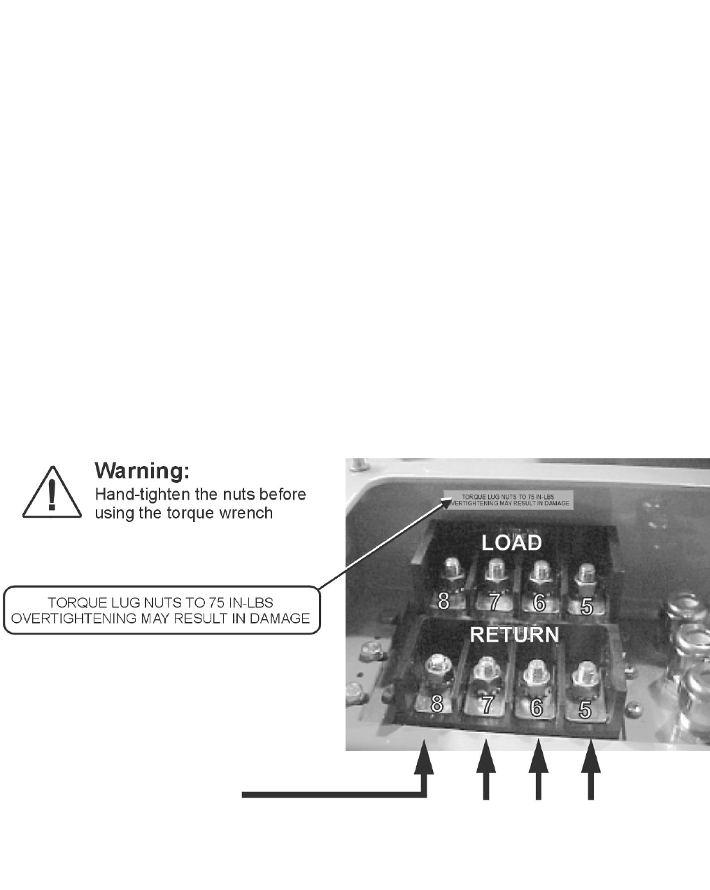
7Connect the 24-VDC return cables (black) to the cabinet DC power
terminal block.
Important! Use the four lower terminals labeled RETURN, and
connect the cables by label number in order from right to left.
Refer to the figure on Page B - 63. Use the applicable terminals
listed in the table on Pages B - 57.
B- 63
Lucent Technologies – Proprietary
See notice on first page
401-703-454
FOA Draft Issue 1
January, 2006
............................................................................................................................................................................................................................................................
................................................................................................................................
............................................
8Hand -tighten the nuts to guard against cross-threading, and then torque
the 5/16-inch, 24-VDC return cable connections to 75 in.-lb. (8 Nm). Do
not use the torque specifications provided in Chapter 1.
................................................................................................................................
............................................
9Connect the +24-VDC cables (red) to the cabinet DC terminal block.
Important! Use the upper terminals labeled LINE (+24 VDC),
and connect the cables by label number in order from right to left.
Use the applicable terminals listed in the table on Pages B - 57.
Refer to the figure below.
................................................................................................................................
............................................
10 Hand-tighten the nuts to guard against cross-threading, and then torque
the four 5/16-inch, +24-VDC cable connections to 75 in.-lb. (8 Nm). Do
not use the torque specifications provided in Chapter 1.
................................................................................................................................
............................................
11 Replace the terminal block cover.
CONNECT 1 AWG HERE IF DUAL
BAND CABINET HAS AN A6
AMPLIFIER SHELF
1 AWG

B- 64 Lucent Technologies – Proprietary
See notice on first page 401-703-454
FOA Draft Issue 1
January, 2006
...........................................................................................................................................................................................................................................................
How to route and connect AC power cables for a 4.0B dual band
.............................................................................................................................................................................................................................................................
Modular Cell cabinet
Overview Important! If installing a primary cabinet, return to Chapter 7 to finish
the installation.
This procedure module provides instructions for the routing and
connection of the AC power cable or cables to a dual band cabinet.
Step-by-step instructions are provided for the following tasks.
Route and connect the WH103 AC cable for the heater from the
primary to the dual band cabinet
B - 66
Route and connect the WH104 AC cable for the convenience
outlet, from the primary to the dual band cabinet (NAR cabinets
only)
B - 70

B- 65
Lucent Technologies – Proprietary
See notice on first page
401-703-454
FOA Draft Issue 1
January, 2006
............................................................................................................................................................................................................................................................
Description of the AC
power cables The installation requires the following AC power cable or cables.
• #10 AWG 3-wire - for the heaters
• #14 AWG 3-wire - for the convenience outlet, if applicable (not
present in international cabinets).
DANGER
Electrical Shock Hazard
Installation of the Modular Cell 4.0B cabinets require
connections to be made that require AC power to be turned off
at specific circuit breakers in the non-Lucent power source.
Failure to follow instructions to turn off these breakers can
create an electrical shock hazard. Failure to follow the order
of the installation procedure (as written) can also create an
electrical shock hazard. The procedures in this manual do not
include safety procedures regarding working on energized
equipment. When this manual is used to install equipment in
an energized system, the appropriate safety procedures must
be followed in addition to the procedures in this manual.
Follow these rules:
1. Perform installation steps in the order provided.
2. Observe and strictly follow all safety precautions.
3. When completing electrical connections, always use
tools that are properly insulated.
B- 66 Lucent Technologies – Proprietary
See notice on first page 401-703-454
FOA Draft Issue 1
January, 2006
...........................................................................................................................................................................................................................................................
Route and connect the
WH103 AC cable for the
heater from the primary to
the dual band cabinet
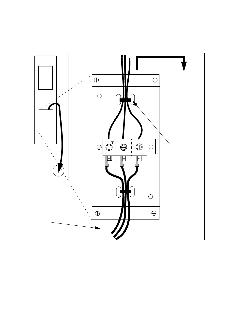
Use the following procedure to route and connect the WH103 heater
AC power cable between the primary and the dual band cabinet. Refer
to the figure on Page B - 45 for the location of the heater junction box
in the primary cabinet. It is in the same location in the dual band
cabinet. Refer to the figure on Page B - 67 for connections.
................................................................................................................................
............................................
1At the non-Lucent power source, set the AC circuit breaker(s) to the
OFF position.
................................................................................................................................
............................................
2Identify the cable that is supplied with the dual band cabinet for the
heater connection. This is the larger (12 AWG) of the two supplied
cables, marked WH103, with three wires marked L1, L2/N and GND
(ground).
................................................................................................................................
............................................
3Strip the ends of the wires on the end of the cable that does not have
spade lugs.
................................................................................................................................
............................................
4Refer to the figure on Page B - 67. Locate and identify the heater
junction box, on the interior right side of the Modular Cell dual band
cabinet.
B- 67
Lucent Technologies – Proprietary
See notice on first page
401-703-454
FOA Draft Issue 1
January, 2006
............................................................................................................................................................................................................................................................
................................................................................................................................
............................................
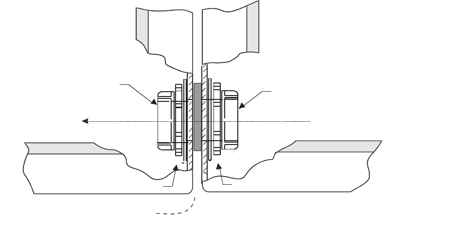
5Connect the stripped ends of the WH103 cable to the screw terminals in
the AC junction box as labeled and shown below. Secure with the
supplied wire tie and install the junction box cover.
1L
2L
GND L1
L2/N
TO
HEATER
WIRE
TIE
WH103
CABLE TO/
FROM THE
MODULAR
CELL 4.0B
PRIMARY
CABINET FRONT
MODULAR CELL 4.0B DUAL BAND CABINET: DETAIL VIEW
HEATER AC
JUNCTION
BOX IN
DUAL BAND
CABINET
B- 68 Lucent Technologies – Proprietary
See notice on first page 401-703-454
FOA Draft Issue 1
January, 2006
...........................................................................................................................................................................................................................................................
................................................................................................................................
............................................
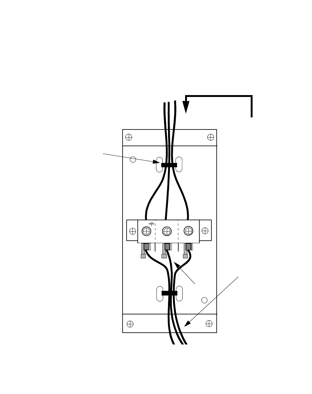
6Route the WH103 cable from the Modular Cell dual band cabinet to the
Modular Cell 4.0B primary cabinet via the conduit coupling between the
cabinets. Refer to the figure below.
BOTTOM FRONT VIEW
2-inch
PLASTIC BUSHING
AREA BETWEEN
CABINETS
LOCK NUT
2-inch
PLASTIC BUSHING
LOCK NUT
MODULAR CELL
4
.0B DUAL BAND CABINET MODULAR CELL
4.0B PRIMARY CABINET
AC CABLE DIRECTION TO
DUAL BAND CABINET
B- 69
Lucent Technologies – Proprietary
See notice on first page
401-703-454
FOA Draft Issue 1
January, 2006
............................................................................................................................................................................................................................................................
................................................................................................................................
............................................
7Remove the cover from the heater junction box in the Modular Cell 4.0B
primary cabinet. Refer to the figure below.
................................................................................................................................
............................................
8Refer to the figure below and connect the spade lugs of the cable to the
top (horizontal) lugs as shown.
................................................................................................................................
............................................
9Secure with the supplied wire tie and install the junction box cover, and
then turn on the breaker (that was set to the OFF position in Step 1).
1L
2L
GND
L1
L2/N
*
*
*
1L
2L
GND L1
L2/N
*
*
*
WH103
CABLE
FROM/TO
MODULAR
CELL 4.0B
DUAL BAND
CABINET
FROM
POWER
SOURCE
WIRE
TIE
* WIRES TO
MODULAR CELL 4.0B
PRIMARY CABINET
HEATERS
NOT SHOWN
HEATER AC
JUNCTION BOX IN
PRIMARY CABINET
MODULAR CELL 4.0B PRIMARY CABINET: DETAIL VIEW
B- 70 Lucent Technologies – Proprietary
See notice on first page 401-703-454
FOA Draft Issue 1
January, 2006
...........................................................................................................................................................................................................................................................
Route and connect the
WH104 AC cable for the
convenience outlet, from
the primary to the dual
band cabinet (NAR
cabinets only)
Use the following procedure to route and connect the WH104
convenience outlet AC cable from the Modular Cell 4.0B primary
cabinet to the Modular Cell 4.0B dual band cabinet (NAR cabinets
only). Refer to the figure on Page B - 45 for the location of the
convenience outlet in the primary cabinet. It is in the same location in
dual band cabinet. Refer to the figure on Page B - 72 for connections.
................................................................................................................................
............................................
1At the non-Lucent power source, set the AC circuit breaker(s) to the
OFF position.
................................................................................................................................
............................................
2Identify the cable that is supplied with the dual band cabinet for the
convenience outlet connection. This is the smaller (14 AWG) of the two
cables, marked WH104, with three wires marked L1, N and GND
(ground).
................................................................................................................................
............................................
3Strip the prepared ends of the three wires on both ends of the cable.
................................................................................................................................
............................................
4Route the WH104 cable from the Modular Cell 4.0B primary cabinet to
the Modular Cell 4.0B dual band cabinet via the conduit coupling
between the cabinets. Refer to the figure on Page B - 68
................................................................................................................................
............................................
5At the Modular Cell 4.0B primary cabinet, remove the cover and the
outlet from the convenience outlet junction box.
................................................................................................................................
............................................
6Remove the indicated knock-outs from both junction boxes, if required.
Refer to the figure on Page B - 72 for the Modular Cell 4.0B primary
cabinet junction box. Refer to the figure on Page B - 73 for the Modular
Cell 4.0B dual band cabinet junction box.

B- 71
Lucent Technologies – Proprietary
See notice on first page
401-703-454
FOA Draft Issue 1
January, 2006
............................................................................................................................................................................................................................................................
................................................................................................................................
............................................
7Loosen the applicable liquid-tight connector on both junction boxes and
route each end of the WH104 cable into their respective junction boxes.
................................................................................................................................
............................................
8 Tighten the liquid-tight connector.
Important! When performing the next step, the location of the
screws may vary depending upon the vendor. Make sure to
connect the wires to the load side of the outlet.
................................................................................................................................
............................................
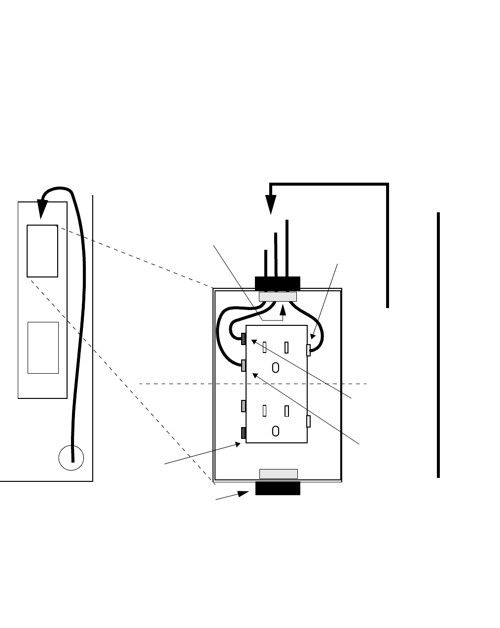
9At the Modular Cell 4.0B primary cabinet convenience outlet junction
box, connect the L1 wire of the WH104 cable to the brass screw, and the
N wire of the WH104 cable to the silver screw on the Load side of the
removed outlet. Refer to the figure on Page B - 72.
................................................................................................................................
............................................
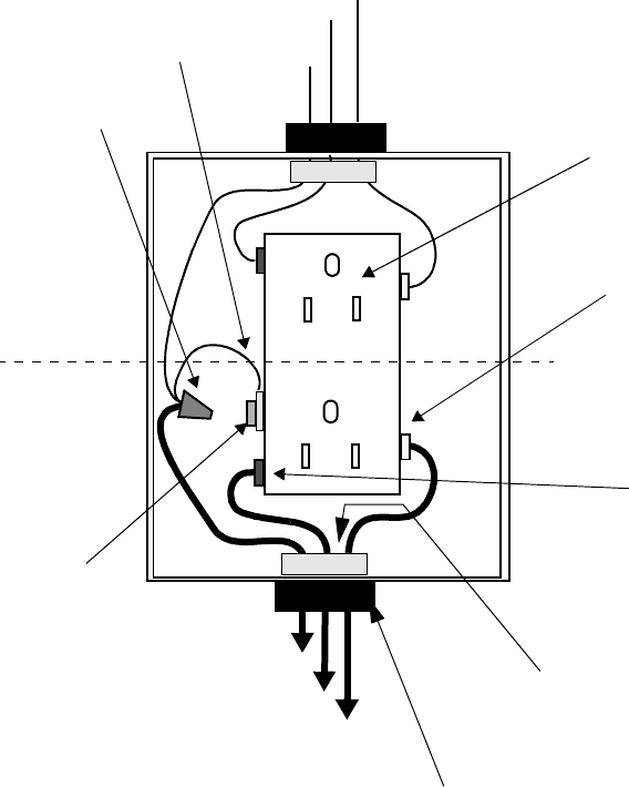
10 At the Modular Cell 4.0B primary cabinet convenience outlet junction
box, connect the ground wire as follows. Refer to the figure on Page B
- 72.
a. Disconnect the power cabinet ground wire (1) from the green
ground screw.
b. Connect the disconnected ground wire (1) to the supplied
pigtail wire (2) and the ground wire of the WH104 cable (3)
using the supplied wire nut.
c. Connect the pigtail wire spade lug to the green ground screw.
B- 72 Lucent Technologies – Proprietary
See notice on first page 401-703-454
FOA Draft Issue 1
January, 2006
...........................................................................................................................................................................................................................................................
................................................................................................................................
............................................
11 Reinstall the outlet in the junction box and replace the cover.
Important! When performing the next step, the location of the
screws may vary depending upon the vendor. Additionally, if the
outlet box is plastic, there will be no ground screw attached to the
box. Refer to the figure on Page B - 73.
L1
G
N
L1
G
N
WH104 CABLE
TO MODULAR
CELL 4.0B DUAL
BAND CABINET LIQUID-TIGHT
CONNECTOR
(1 of 2)
OUTLET
SILVER
SCREW*
BRASS
SCREW*
* SCREW
LOCATIONS MAY
VARY BY OUTLET
VENDOR
GREEN
SCREW*
LOAD
SIDE
LINE
SIDE
FROM POWER
SOURCE
WIRE NUT
PIGTAIL
WITH SPADE
LUG
(1)
(2)
(3)
KNOCK-OUT
LOCATION
MODULAR CELL 4.0B PRIMARY CABINET: DETAIL VIEW
CONVENIENCE
OUTLET IN
PRIMARY
CABINET
B- 73
Lucent Technologies – Proprietary
See notice on first page
401-703-454
FOA Draft Issue 1
January, 2006
............................................................................................................................................................................................................................................................
................................................................................................................................
............................................
12 At the Modular Cell 4.0B dual band cabinet convenience outlet junction
box, connect the wires of the WH104 cable to the correct screw terminal
on the line side of the removed outlet, as follows. Refer to the figure
below.
• Wire marked L1 to brass screw
• Wire marked L2/N to silver screw
• Wire marked GND to the green screw.
................................................................................................................................
............................................
13 Install the outlet in the junction box and install the cover, and then turn
on the breaker (that was set to the OFF position in Step 1).
OUTLET
L1
GN
LOAD
SIDE
LINE
SIDE
BRASS
SCREW*
GREEN
SCREW*
SILVER
SCREW*
* SCREW LOCATIONS MAY VARY BY OUTLET VENDOR
LIQUID-TIGHT
CONNECTOR (1 of 2)
WH104 CABLE
FROM
MODULAR CELL
4.0B PRIMARY
CABINET
KNOCK-OUT
LOCATION
MODULAR CELL 4.0B DUAL BAND CABINET: DETAIL VIEW
FRONT
CONVENIENCE
OUTLET IN DUAL
BAND CABINET
B- 74 Lucent Technologies – Proprietary
See notice on first page 401-703-454
FOA Draft Issue 1
January, 2006
...........................................................................................................................................................................................................................................................
.............................................................................................................................................................................................................................................................
Finishing the installation
Finish the installation If an any additional cabinet remains to be installed during the current
installation, proceed to the applicable chapter or appendix at this time.
If all cabinets have been installed, refer to the appropriate sections of
Chapter 7 to finish the installation.

C- 1
Lucent Technologies – Proprietary
See notice on first page
401-703-454
FOA Draft Issue 1
January, 2006
............................................................................................................................................................................................................................................................
Appendix C: Post-installation
checklists by cabinet
.............................................................................................................................................................................................................................................................
Post-installation checklists
Overview This appendix contains instructions for using the post-installation
checklists along with the checklists for the following cabinets, plus the
(final) punchlist.
The following post-installation checklists may be used by all installers
to record completion of individual installation requirements. To use the
checklists, make a copy of each page, as applicable, for each
installation. Chapter, or other document references are given in the
event that a particular requirement requires review. Note that the
checklists are followed by an "Installation Punchlist Sheet". For
instructions on how to use the checklists and the Installation Punchlist
Sheet, refer to Instructions for use of the checklists and punchlist on page
C-2.
Instructions for use of the checklists and punchlist C-2
IN1: Modular cell cabinets C-3
IN1: Modular cell cabinets (continued) C-5
IN1: Modular cell cabinets (continued) C-7
IN2: WNG24-BC battery cabinets and EZBFo battery frames
(first or second)
C-9
IN3: Installation Punchlist Sheet C-11
C- 2 Lucent Technologies – Proprietary
See notice on first page 401-703-454
FOA Draft Issue 1
January, 2006
...........................................................................................................................................................................................................................................................
Instructions for use of the
checklists and punchlist The checklist tables that follow list the post-installation requirements
for the Flexent Modular Cell Cabinets, as well as for the first and
second WNG24-BC battery cabinets, or first and second EZBFo
battery frames. They also provide columns for indicating compliance or
non-compliance (Yes or No), and a column to indicate "not applicable"
(N/A). The Chapter Reference (Ch. Ref.) column provides the specific
chapter for each installation procedure, or “Doc. 401-200-115” for
grounding specifications. An “N/A” entry indicates that the question
does not necessarily relate to EDs or the Installation Manual. Use the
following directions to use the checklists, and the punchlist that follows
at the end.
................................................................................................................................
............................................
1Make copies of sheets IN-1 and IN-3, as applicable to the specific
installation.
................................................................................................................................
............................................
2Fill out IN-1 sheets (and the IN-2 sheet, if applicable) according to the
following instructions.:
• For each checklist sheet, fill in the cabinet serial number.
• For each item check the “Yes”, “No” or “N/A” column, as
applicable.
Important! Observe that the right-hand column labeled “Ch.
Ref.” lists the specific chapter for each installation procedure, or
“Doc. 401-200-115” for grounding specifications. An “N/A” entry
indicates that the question does not necessarily relate to EDs or the
Installation Manual.
................................................................................................................................
............................................
3Make multiple copies of sheet IN-3, as needed.
................................................................................................................................
............................................
4Fill out sheet(s) IN-3, the “Installation Punchlist”, using the “No”
column entries from sheets IN-1 (and IN-2, if applicable), and add
comments for each.
................................................................................................................................
............................................
5Retain the completed sheets.

C- 3
Lucent Technologies – Proprietary
See notice on first page
401-703-454
FOA Draft Issue 1
January, 2006
............................................................................................................................................................................................................................................................
.............................................................................................................................................................................................................................................................
IN1: Modular cell cabinets
Overview The table below lists the post-installation requirements for the Flexent
Modular Cell Cabinets.
Serial number Modular Cell Cabinet Serial Number:_______________________________
Item/Description Yes No N/A Ch. Ref.
1. Is the cabinet secured to a sub-structure per earthquake zoning
requirements?
2
2. Is the cabinet properly grounded? 2
3. Have the cable conduits been properly installed & sealed? 2
Have eye bolts been replaced with filler bolts and washers? 2
4. Have proper drip loops been provided in RF cable runs at the
antenna cable cover?
2/7
5. Is weatherization properly installed and are all covers /
conduits sealed and screws tightened?
2/7
6. Are all RF & DC cable connections torqued to the appropriate
value?
2/4/7
7. Are RF cable connections weatherproofed? 2/7
8. Have wire protection bushings been installed on AC wiring
conduits?
2/4
9. Have all unused EMI feed-through connectors been sealed
with a piece of wire or filler plug? (For example, insert a
plastic plug or a 3” piece of #6 AWG wire or equivalent).
3
10. Are all used EMI feed-through connectors properly tightened? 3
11. Have all ancillary hardware seams been sealed per Lucent Site
Preparation documentation?
N/A
C- 4 Lucent Technologies – Proprietary
See notice on first page 401-703-454
FOA Draft Issue 1
January, 2006
...........................................................................................................................................................................................................................................................

C- 5
Lucent Technologies – Proprietary
See notice on first page
401-703-454
FOA Draft Issue 1
January, 2006
............................................................................................................................................................................................................................................................
.............................................................................................................................................................................................................................................................
IN1: Modular cell cabinets (continued)
Serial number Modular Cell Cabinet Serial Number:_______________________________
Item/Description Yes No N/A Ch. Ref.
12. Are the heat exchanger air intake & exhaust vents free of
debris and unobstructed?
N/A
13. Have all external alarms been connected to the cabinet punch-
down block?
3
14. Have facilities twisted pairs been connected to the cabinet
punch-down block?
3
15. Are protectors plugged in for all applicable alarm and TELCO
signals?
3
16. Is a surge protector present, connected and torqued correctly
for each antenna (including GPS)?
3/7
17. Is the heater AC circuit breaker in the ON position? 7
18. Is the equipment properly frame-grounded per Lucent Doc.
401-200-115 specifications?
Please note conductor(s) quantity, size &
type:______________
Doc.
401-
200-115
19. Are all DC circuit breakers for installed equipment in the ON
position?
7
20. Have all installation & integration tests been completed? N/A
21. Are all DC fuses properly installed? N/A
22. Have all doors, covers, panels, etc. been properly installed on
cabinets?
7
23. Are all panel/door latches in the locked position? 7
C- 6 Lucent Technologies – Proprietary
See notice on first page 401-703-454
FOA Draft Issue 1
January, 2006
...........................................................................................................................................................................................................................................................

C- 7
Lucent Technologies – Proprietary
See notice on first page
401-703-454
FOA Draft Issue 1
January, 2006
............................................................................................................................................................................................................................................................
.............................................................................................................................................................................................................................................................
IN1: Modular cell cabinets (continued)
Serial number Modular Cell Cabinet Serial Number:_______________________________
Item/Description Yes No N/A Ch. Ref.
24. Are rectifier output voltages set to accommodate battery plant
float voltage?
N/A
25. Is the battery temperature compensation probe connected? 5
26. Has proper spacing around the cabinet been provided per
Lucent Site Preparation documentation?
N/A
27. Are all rectifiers properly seated in each shelf? 5
28. Are all battery, AC, and DC cable connections properly
torqued?
4/5
29. Are power alarm indicators (LEDs) extinguished? N/A
30. Have battery retaining brackets been properly installed? 5
31. Is the main circuit breaker in the ON position? 7
32. Is the battery heater AC circuit breaker in the ON position (if
applicable)?
7
33. Are all in-use AC circuit breakers in the ON position? [Note:
Leave unused circuit breaker(s) in the OFF position.]
7
34. Are battery quick disconnects properly mated (or battery
disconnect circuit breakers ON) for strings in use?
5
35. Are battery compartment vents free of debris and
unobstructed?
7
36. Has required battery information been recorded and provided
to the customer?
5
37. Are rectifier output voltages set to accommodate battery plant
float voltage (if applicable)?
N/A
C- 8 Lucent Technologies – Proprietary
See notice on first page 401-703-454
FOA Draft Issue 1
January, 2006
...........................................................................................................................................................................................................................................................

C- 9
Lucent Technologies – Proprietary
See notice on first page
401-703-454
FOA Draft Issue 1
January, 2006
............................................................................................................................................................................................................................................................
IN2: WNG24-BC battery cabinets and EZBFo battery frames (first or
.............................................................................................................................................................................................................................................................
second)
Overview The table below lists the post-installation requirements for the first or
second WNG24-BC battery cabinets or EZBFo battery frames.
WNG24-BC Battery Cabinet Serial Number:_______________________________
Item/Description Yes No N/A Ch. Ref.
1. Have eye bolts been replaced with filler bolts and washers? 2/App D
2. Is the cabinet / rack properly secured to a sub-structure per
Lucent Engineering Drawings & earthquake zoning
requirements?
2/5/App
D
3. Have the correct type & number of batteries been installed? 5/App D
4. Are battery temperature compensation probes connected to
60C power cabinet interface cables?
5/App D
5. Are all interface conduits sealed (outdoor only)? 5/App D
6. Is the backup cabinet AC circuit breaker in the power cabinet
in the ON position?
5/App D
7. Are battery compartment vents free of debris and
unobstructed?
N/A
8. Are battery quick disconnects properly mated? 5/App D
9. Have battery retaining brackets been properly installed? 5/App D
10. Is equipment grounded per Lucent Doc. 401-200-115
specifications? Please note conductor quantity, size &
type:______________
Doc.
401-
200-115
11. Are all panel/door latches in the locked position? 5/App D
12. Has required battery information been recorded and provided
to the customer?
N/A
13. Are all power and alarm interface cables connected and the
cable access ports sealed properly?
5/App D
C- 10 Lucent Technologies – Proprietary
See notice on first page 401-703-454
FOA Draft Issue 1
January, 2006
...........................................................................................................................................................................................................................................................
C- 11
Lucent Technologies – Proprietary
See notice on first page
401-703-454
FOA Draft Issue 1
January, 2006
............................................................................................................................................................................................................................................................
.............................................................................................................................................................................................................................................................
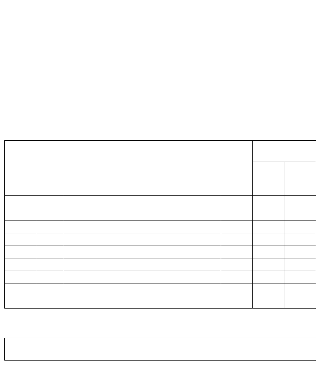
IN3: Installation Punchlist Sheet
Severity Column
Definitions: 1. Equipment installation is not complete and may void the warranty,
potentially cause personal injury or prevent RF optimization from
occurring.
2. Equipment installation is not complete. RF optimization can occur
but items must be rectified prior to handoff to customer or service
turn-up so that the warranty is not voided.
3. RF optimization, handoff to customer or service turn-up can
occur, but not per Lucent recommendations.
Inspection Checklist Completion Sign-off:
Check-
list Sheet
Number
Item
#
Comment/Description Severity
(1/2/3)
Corrective
Action Required
(Y/N Comp.
Date
Inspector’s Name: Inspector’s Function:
Inspector’s Signature: Date:
C- 12 Lucent Technologies – Proprietary
See notice on first page 401-703-454
FOA Draft Issue 1
January, 2006
...........................................................................................................................................................................................................................................................

GLOSSARY
GL-1
Lucent Technologies – Proprietary
Use pursuant to company instructions
401-703-454
FOA Draft Issue 1
January, 2006
............................................................................................................................................................................................................................................................
.............................................................................................................................................................................................................................................................
Glossary
0-9 12IR125
Battery designed to withstand the rigors of harsh environments and uncontrolled
temperatures.
24 VDC
DC connection block for 24-volt power source (See VDC).
240 VAC
AC connection block for 24-volt power source (See VAC).
-48 VDC
DC connection block for 48-volt power source.
60ECv2
Battery cabinet which provides additional backup batteries to supplement the
batteries in the PowerHouse24/G cabinet.
60ECv2G
Version of the 60ECv2 battery cabinet for connection to the "G" version of the
PowerHouse24 cabinet for additional backup batteries.
850 CDMA
CDMA technology in the Cellular Frequency Band (824-894 MHz).
A AC (Alternating Current)
Continuously varialbe current, rising to a maximum in one direction, falling to
zero, then reversing direction and repeat the cycle in the other direction.
AC convenience outlet
Modular Cell sites must be equipped with at least two duplex outlets for installation
and maintenace procedures. The outlets are required to power test equipment and
installation tools.
GLOSSARY
GL-2 401-703-454
FOA Draft Issue 1
January, 2006
.........................................................................................................................................................................................................................................................
Lucent Technologies – Proprietary
Use pursuant to company instructions
.............................................................................................................................................................................................................................................................
AC distribution panel
Module equipped with various circuit breakers and fuses which provides AC
power to various equipment.
AC interface kit
Hardware installed between Modular Cell Cabinet #1 and the PowerHouse24
cabinet, which provides a weatherproof conduit for routing AC power cables.
Ambient temperature
The temperature of air or other media in a designated area, particularly the area
surrounding the equipment.
Anchor
Device that is buried in the ground and fastened to the cabinet for stability.
Antenna
An elevated device for radiating or receiving radio waves. It changes electrical
currents into electromagnetic waves, and vice versa.
Antenna cable cover
A section on the top-rear of the outdoor Modular Cell cabinets which provides a
weather resistant housing for antenna cables.
ANSI (American National Standards Institute)
The U.S. standards organization that establishes procedures for the development
and coordination of voluntary American standards.
AWG (American Wire Guage)
American wire guage standard
B Backup
Facility used to replace an element which has failed.
Boom line
Rope extended from a derrick or other lifting device used for lifting a cabinet.
Boot
Weather resistant connection for GPS and RF jumper cables.
Bus bar
One or more conductors that serve as a common connnection for a group of related
devices.

GLOSSARY
GL-3
401-703-454
FOA Draft Issue 1
January, 2006
...........................................................................................................................................................................................................................................................
Lucent Technologies – Proprietary
Use pursuant to company instructions
.............................................................................................................................................................................................................................................................
C CDMA (Code Division Multiple Access)
Assigns each active call a unique pseudonoise code that is used by the system to
distinguish that call from all other calls that occupy the same CDMA carrier band.
CDMA uses spread-spectrum digital modulation techniques.
Cell
A geographical area, usually depicted as hexagon-shaped, that is served by a
cellular system. Cellular technology is based on the premise that a group of radio
frequencies used within one cell can be used again in distant cells.
Cell site
An installation located within a cell that houses the equipment needed to set up and
complete calls on cellular telephones; for example, FM radio transmitter and
receiver equipment, antennas and computers.
Circuit
1. The complete path between two terminals over which one-way or two-way
communications may be provided. 2. An electronic path between two or more
points, capable of providing a number of channels. 3. A number of conductors
connected together for the purpose of carrying an electrical current. 4. An
electronic closed-loop path among two or more points used for signal transfer. 5. A
number of electrical components, such as resistors, inductances, capacitors,
transistors, and power sources connected together in one or more closed loops.
CLGC
Closed Loop Gain Control.
CO (Central Office)
Grounding cable that is connected to the facility ground bus bar on the power
frame.
Cord grip seal assembly
EMI/RF1 liquid-tight fitting for T1/E1, user alarms, and power alarm cables.
C-tap
Clamp used to connect a power lead to a main power conductor without breaking
and terminating the conductor.
GLOSSARY
GL-4 401-703-454
FOA Draft Issue 1
January, 2006
.........................................................................................................................................................................................................................................................
Lucent Technologies – Proprietary
Use pursuant to company instructions
.............................................................................................................................................................................................................................................................
.............................................................................................................................................................................................................................................................
D DC (Direct Cuurent)
Current flow in one direction.
DC distribution panel
Module equipped with various cricuit breakers and/or fuses to provide DC current
to load.
DIN (Deutsches Institute fur Normung)
Germany’s standards-setting organization.
Drip loop
A cable which has been curved with the arc facing the ground to prevent water from
flowing to the connectors at either end of the cable. When it rains, the water drips
from the lowest point of the curve towards the ground.
Dual Band
A dual band cabinet is a growth cabinet in which one or more of the carriers are of
a different band than the carriers in the primary cabinet.
EE1
A four-wire voice and data trunking facility that carries 30 duplex channels in 64-
kbps time slices. E1 facilities are standard for digital telecommunications in all
continents except for North America.
Earthquake zone
Seismic ratings ranging from zone 1 (relatively low central office operational
shock and vibration levels) to the most severe zone 4 levels. Equipment must be
able to withstand earthquake zone requirements under both operational and non-
operational conditions.
ED (Equipment Drawings)
Provides cabinet layout, dimensions, and installation requirements.
EMI (Electromagnetic Interference)
Any electromagnetic disturbance that interrupts, obstructs, or otherwise degrades
or limits the effective performance of electronics or electrical equiupment
(see RFI).
ESD
Electro Static Discharge
External User Alarms
Alarms generated external to the Modular Cell Cabinet #1, but routed to its punch-
down block for reporting purposes.

GLOSSARY
GL-5
401-703-454
FOA Draft Issue 1
January, 2006
...........................................................................................................................................................................................................................................................
Lucent Technologies – Proprietary
Use pursuant to company instructions
.............................................................................................................................................................................................................................................................
.............................................................................................................................................................................................................................................................
.............................................................................................................................................................................................................................................................
F Facility Interface Panel
Pull-down component on Modular Cell Cabinet #1 where the punch-down terminal
block is located for terminating T1/E1, user alarm, and power system alarms.
Feed
To supply a signal to the input of a system, subsystem, equipment or component,
such as a transmission line or antenna.
Filter
A frequency selective network that transmits/recieves signals of desired
frequencies while greatly attenuating all other frequencies.
Fish tape
Narrow, springy steel tape designed for pushing through short lengths of ducting in
order to pull cables in from the far end.
Flexent
Registered trademark of Lucent Technologies.
G GND (Ground)
See Ground.
GPS (Global Positioning System)
A system of 24 satellites that provide, among other things, extremely accurate
timing information to CDMA-equipped cell sites.
Ground
A conducting connection between equipment or an ectrical circuit and earth, or
other conductive body that is used in place of the earth.
Grounding Electrode System
The conductive objects that are intentinally bonded to furnish connection to earth
(i.e. buried ring ground with ground rods, electrically continuous buried metallic
water pipe, electrolytic ground electrode, etc.).
I IDC (Insulation Displacement Connector)
Block which provides electrical protection and/or termination location inside the
Modular Cell cabinet.
Interconnect
Linkage used to join two or more communications units, or equipment.
GLOSSARY
GL-6 401-703-454
FOA Draft Issue 1
January, 2006
.........................................................................................................................................................................................................................................................
Lucent Technologies – Proprietary
Use pursuant to company instructions
.............................................................................................................................................................................................................................................................
.............................................................................................................................................................................................................................................................
.............................................................................................................................................................................................................................................................
.............................................................................................................................................................................................................................................................
J Jumper
Connections between terminal blocks on the two sides of a distribution frame.
Junction box
Steel box inside equipment where low-voltage power cable joints are made.
K Knockout
Discs partially punched out on the side or base of a terminal or junction box to the
appropriate size for feeding cable into the box.
L Landline
A telephone accessed by landline media.
Lifting eyes
Bolts located on the top of the cabinet for connecting slings to lift the cabinet.
Line side
Portion of a device that is connected to an external facility that provides power
from a power source.
Load side
Portion of a device that is connected to an external facility that is using the power
from a power source.
Lugs
A tag or projecting terminal onto which a wire may be connected by crimping or
soldering.
M Modular Cell
Provides radio access interfaces and radio resources management functions, as
well as call handling with the 5ESS Switch at Cellular and PCS frequencies.
Multiplexer
Equipment that provides a means of transmitting two or more signals over the same
transmission path.
MGB (Main Bus Bar)
A copper bus bar used to provide the electrical interface for connection of the
isolated ground plane to the integrated ground system.

GLOSSARY
GL-7
401-703-454
FOA Draft Issue 1
January, 2006
...........................................................................................................................................................................................................................................................
Lucent Technologies – Proprietary
Use pursuant to company instructions
.............................................................................................................................................................................................................................................................
.............................................................................................................................................................................................................................................................
.............................................................................................................................................................................................................................................................
N NAR
North American Region
NEC (National Electric Code)
Standard that governs the use of electrical wire, cable, and fixtures, and electrical
and optical communication cable installed in buildings.
NFPA (National Fire Prevention Association)
Standards and code writing organization made up of volunteer industrial and institutional subject-matter-
expert committees.
Neutral ground
An intentional ground applied to a neutral conductor or neutral point of a circuit,
equipment, or system.
Network Interface
The demarcation between the LEC infrastructure and the Customer Premises
Equipment (CPE). Equipment located at this point is intended to allow the LEC to
determine whether transmission problems are within the network itself or the CPE.
O OA&M (Operation, Administration, and Maintenance)
Generic name given to functions such as technical interfaces, diagnostics, service
measurements, and status reports.
OMP (Operation Management Platform)
This component provides a centralized point of access for wireless systems
operation and maintenance. The OMP provides a dedicated processor from which
system operators can perform multiple operation, administration, and maintenance
(OA&M) tasks simultaneously.
Open circuit
A path that contains an infinite impedance, and is available for use.
P Paired cable
Cable made up of one or more separately insulated twisted-wire pairs, none of
which is arranged with another to form quads.
Panelboard
A flat board consisting of buses and automatic over-current devices with or without
switches, for the control of electrical circuits. The panelboard is designed to be
placed in a cabinet with only front access.
PCS (Personal Communications Services)
Services for digital RF equipment operating in the 2-GHz spectrum.
GLOSSARY
GL-8 401-703-454
FOA Draft Issue 1
January, 2006
.........................................................................................................................................................................................................................................................
Lucent Technologies – Proprietary
Use pursuant to company instructions
.............................................................................................................................................................................................................................................................
PCB (Power Circuit Breaker)
The primary switch used to apply and remove power from equipment. Used on AC
circuits rated in excess of 1500 V.
Pigtail
A short lenght of electrical conductor permanently affixed to a component, used to
connect the component to another.
Positive terminal
The terminal from which conventional current leaves the battery.
PowerHouse™ 24 cabinet
Power cabinet for typical outdoor Modular Cell Site using 24 volts power source.
PowerHouse™ 24G cabinet
Global version of the PowerHouse24 cabinet for outdoor Modular Cell Site using
24 volts power source. This power cabinet has a different AC distribution panel,
and convineince outlets are not equipped with the cabinet.
Pull-box
Small box with abovc-ground access which is inserted in a long run single conduit
to facilitate pulling a cable through the duct.
Punch-down terminal block
Used for terminating T1/E1, User alarms, and power cables. The bolck is located
in the facility interface panel inside the Modular Cell Cabinet #1.
RRectifiers
Device for converting alternating current (AC) into direct current (DC).
Return
A return path for current.
RF (Radio Frequency)
The electromagnetic wave used for, among other things, cellular voice and data
communications.
RFI (Radio Frequency Interference)
See EMI.
RTV
Silicone used for sealing or podding compound.

GLOSSARY
GL-9
401-703-454
FOA Draft Issue 1
January, 2006
...........................................................................................................................................................................................................................................................
Lucent Technologies – Proprietary
Use pursuant to company instructions
.............................................................................................................................................................................................................................................................
.............................................................................................................................................................................................................................................................
SShield
A housing, screen, shealth, or cover that substantially reduces the coupling of
electric, magnetic, or electromagnetic fields into or out of circuits or transmission
lines.
Short circuit
A direct low resistance connection between conductors not normally in contact
with each other.
STBY (Standby)
System operations pertaining to a power saving condition or status of operation of
equipment that is ready for use, but not in use.
String
A series of elements considered as a whole.
Surge protector
Protective device used to limit surge voltages by discharging or bypassing any
unwanted surge current that may enter a building or equipment.
System test
Test performed after installation and power-up of the cabinets, and after GPS
antenna jumper cable is connected. The RF jumper cable is not connected during
testing.
TT1
A four-wire voice and data trunking facility that carries 24 duplex channels over
56-kbps time slots.
Terminal
A device capable of sending, receiving or sending and receiving information over
a communications channel.
Thermal Probe
Device used for sensing the temperature of an object or air.
TIP N TELL
Indicator on cabinet’s package that indicates if the cabinet was mishandled or
tipped during shipment.
GLOSSARY
GL-10 401-703-454
FOA Draft Issue 1
January, 2006
.........................................................................................................................................................................................................................................................
Lucent Technologies – Proprietary
Use pursuant to company instructions
.............................................................................................................................................................................................................................................................
.............................................................................................................................................................................................................................................................
.............................................................................................................................................................................................................................................................
TDMA
Time Division Multiple Access. TDMA divides each carrier frequency into a
number of time slots, each of which constitutes an independent telephone circuit.
Current North American digital systems use TDMA.
Torque
Moment of force acting on a body and tending to produce rotation about an axis.
Twisted-pair cable
See Paired cable.
U UL (Underwriters Laboratories)
Laboratories that test materials and equipment against pre-determined
performance standards.
Upgrade
To improve service by offering better facilities.
W Weatherproof
Designed to be used outdoors under any number of specified climatic conditions.
Z Zero Clearance Installation
Cabinets are placed in close proximity to a wall or other structure, and the available
space behind the cabinet does not permit the installer to access the rear cabinet
mounting brackets.