Alvarion Technologies MICRO-25 Microbase station transceiver User Manual 4Motion System Manual
Alvarion Technologies Ltd. Microbase station transceiver 4Motion System Manual
Contents
- 1. Manual p1
- 2. Manual p2
- 3. Manual p3
- 4. Manual p4
- 5. Manual p5
Manual p2

Chapter 3 - Operation and Administration of the Macro BTS Managing Software Upgrade
4Motion 101 System Manual
3.2.2.1.2 Step 2: Triggering Software Download
After the TFTP server is configured, run the following command to trigger the
download of the shadow image to be used for software upgrade:
npu(config)# load to shadow <shadow image name>
After you execute this command, the shadow image is downloaded to the NPU
flash, and the shadow image that is currently residing in the flash is overwritten.
Command
Modes
Global configuration mode
NOTE
After you have configured the TFTP server, you can, at any time, view the TFTP server
configuration information. For more details, refer to “Displaying the TFTP Configuration
Information” on page 104.
IMPORTANT
An error may occur if you execute this command when:
Another software download is already in progress.
The shadow image to be downloaded is already residing in the NPU flash as the shadow or
operational image.
The TFTP server is not configured. For more information about configuring the TFTP server,
refer to “Step 1: Configuring the TFTP Server” on page 100.
The name of the shadow image to be downloaded is incorrect or the format of the file name is
incorrect. Because the file to be downloaded is a compressed file, always be suffix the file
name with .tgz.
The NPU is running with the shadow image.
The system does not have enough memory available for software download.
Command
Syntax
npu(config)# load to shadow <shadow image name>

Chapter 3 - Operation and Administration of the Macro BTS Managing Software Upgrade
4Motion 102 System Manual
3.2.2.1.3 Step 3: Resetting and Booting the NPU Using the Shadow Image
After the shadow image is downloaded to the NPU flash, run the following
command to reboot the NPU with the downloaded shadow image:
npu(config)# reboot from shadow [<shadow image name>]
In the above command, you can specify the shadow image name that is to be used
for NPU reboot. If you do not specify a value for the shadow image name
parameter, the shadow image that was last downloaded is used for rebooting the
NPU.
Syntax
Description Parameter Description Presence Default
Value
Possible
Values
<shadow
image name>
Denotes the name of the
shadow image that is to be
downloaded to the NPU flash.
The name of this file should
always be suffixed with .tgz.
Mandatory N/A <Valid shadow
image
name>.tgz
Command
Modes
Global configuration mode
NOTE
After you have triggered the download procedure, you can at any time, obtain information about the
download status. For more details, refer to “Displaying the Download Status Information”
on page 105.
Command
Syntax
npu(config)# reboot from shadow [<shadow image name>]
Syntax
Description Parameter Description Presence Default
Value
Possible Value
<shadow
image name>
Denotes the name of the
shadow image that is to be
used for rebooting the NPU.
If you do not specify a value
for this parameter, the last
downloaded shadow image is
used for rebooting the NPU.
Optional N/A Valid shadow
image name

Chapter 3 - Operation and Administration of the Macro BTS Managing Software Upgrade
4Motion 103 System Manual
3.2.2.1.4 Step 4: Making the Shadow Version Operational
After you reset the NPU with the shadow image, and ensure that the NPU is
functioning correctly with the shadow image, you can make the shadow version as
the operational version. The next time you reset the system, the shadow image
that you make operational is used for rebooting the NPU.
To make the shadow version as the operational version, run the following
command.
npu(config)# switchover npu
After you run this command, the operational image is swapped with the shadow
image. The next time you reset the NPU, the system boots up with the swapped
image.
3.2.2.2 Displaying the Operational, Shadow, and Running Versions
You can, at any time (during or after the software download procedure), run the
following command to view the operational, shadow, and running versions of the
NPU software:
npu# show software version npu
Command
Modes
Global configuration mode
IMPORTANT
If you reset the NPU before running this command, the NPU boots up with the image that is
currently the operational image.
IMPORTANT
An error may occur if you run this command when the NPU is not running with the shadow image.
Command
Syntax
npu(config)# switchover npu
Command
Modes
Global configuration mode
Chapter 3 - Operation and Administration of the Macro BTS Managing Software Upgrade
4Motion 104 System Manual
3.2.2.3 Displaying the TFTP Configuration Information
You can, at any time (during or after the download procedure), run the following
command to view the configuration information about the TFTP server that is
used for the NPU software upgrade:
npu# show software version server
NOTE
The operational version is the default software version that is used for rebooting the NPU after
system reset.
The shadow version is the downloaded software version that you can use to boot up the NPU.
However, it is the operational software version that is used to boot up the NPU after the next system
reset.
The running version is the software version (can be either the operational or shadow version) that is
currently running on the system.
Command
Syntax
npu# show software version npu
Display
Format
Mananged Object : NPU
Operational Version : <Operational Version>
Shadow Version : <Shadow Version>
Running Version : <Running Version>
Command
Modes
Global command mode
IMPORTANT
An error may occur if configuration information is requested for a TFTP server that is not configured.
For more information about configuring the TFTP server to be used for software download, refer to
“Step 1: Configuring the TFTP Server” on page 100.
Command
Syntax
npu# show software version server
Display
Format
Software version server <Server IP Address>

Chapter 3 - Operation and Administration of the Macro BTS Managing Software Upgrade
4Motion 105 System Manual
3.2.2.4 Displaying the Download Status Information
After initiating software download, you can, at any time, view the download
progress for the NPU image. The progress of the image download procedure can be
in any of the following stages:
No Software Download has been initiated
Downloading
Decompressing
Validating
Copying
Writing to flash
Download complete
An error may occur while:
Downloading the software image from the TFTP server
Decompressing the downloaded file
Validating the downloaded file
Copying of the software image to the NPU flash
Run the following command to view the download status:
npu# show download status npu
After you run the above command, the TFTP server address, image name and
version, download status, and the number of bytes that have been downloaded,
are displayed.
Command
Modes
Global command mode

Chapter 3 - Operation and Administration of the Macro BTS Managing Software Upgrade
4Motion 106 System Manual
3.2.3 Upgrading the AU
To upgrade the AU software, first configure the TFTP server that you want to use
for software version download, and then download the image to the NPU flash.
You can store up to three images to be used for AU upgrade. You are required to
create a mapping between the AU slot and the image residing in the NPU flash.
Each time the AU is reset or if you are inserting/re-inserting the AU card in the
AU slot for, the AU boots up using the AU-to-image mapping that you specify.
You can specify separate AU-to-image mappings for each AU slot. In addition, you
are required to create a mapping that is to be used as the default mapping. This
default mapping is used for boot up all AU slots for which a mapping does not
exist. After you have created the mapping, download the mapped image from the
NPU flash to the AU flash (for the AU slot for which the mapping is created). You
can then reboot the AU using the downloaded image. After mapping you can also
just reboot the AU(s) that after reboot will perform SW upgrade automatically.
If the image that you have used to reboot the AU is not the image currently
mapped to this AU slot, the AU-to-image mapping for that AU slot is updated with
this image (provided you have not deleted this image from the NPU flash before
rebooting the AU).
IMPORTANT
An error may occur if you execute this command when no download procedure is in progress.
Command
Syntax
npu# show download status npu
Display
Format
Mananged Object : NPU
Image Name : <Downloaded Image Name>
Software version server : <IP Address of TFTP Server>
Download Status : <Download Status>
Download Bytes : <Bytes Downloaded>
Command
Modes
Global command mode

Chapter 3 - Operation and Administration of the Macro BTS Managing Software Upgrade
4Motion 107 System Manual
3.2.3.1 Procedure for Upgrading the AU
“Step 1: Configuring the TFTP Server” on page 107
“Step 2: Downloading the AU Image to the NPU Flash” on page 108
“Step 3: Creating the AU-to-Image Mapping” on page 109
“Step 4: Downloading the Image to the AU Flash” on page 110
“Step 5: Resetting and Rebooting the AU with the Shadow Image” on page 111
3.2.3.1.1 Step 1: Configuring the TFTP Server
To create an AU-to-image mapping, you need to first configure the TFTP server to
be used for downloading the image to the NPU flash.
Run the following command to configure the TFTP server to be used for software
version download.
IMPORTANT
Before inserting an AU card, ensure that an AU-to-image mapping exists, which is to be used for
booting the AU. If you insert the AU card when there is no existing mapping, the AU is immediately
shut down. For more information about creating a (default) AU-to-image mapping, refer “Step 3:
Creating the AU-to-Image Mapping” on page 109.
After you create the AU-to-image mapping, execute the following command (for details refer
Section 3.2.3.1.5).
npu(config)# reboot au [<au slot-id>] shadow [<shadow image name>]
After you execute this command, the AU boots up with the mapped image.
To execute the AU upgrade procedure:
IMPORTANT
If you are inserting/re-inserting the AU card, you are required to execute this procedure before
inserting and powering up the AU card. If an error occurs while booting up of the AU, it is reset upto
three times, after which it is completely shut down.
IMPORTANT
The same TFTP server is used for downloading the software image to be used for upgrading the
NPU/AU. For detailed information about the configuring the TFTP server, refer
Section 3.2.2.1.1.

Chapter 3 - Operation and Administration of the Macro BTS Managing Software Upgrade
4Motion 108 System Manual
npu(config)# software version server <server ip>
3.2.3.1.2 Step 2: Downloading the AU Image to the NPU Flash
After the TFTP server is configured, run the following command to download the
AU image (to be used for software upgrade) to the NPU flash:
npu(config)# Download AU image <AU image name>
After you execute this command, the AU image is downloaded to the NPU flash.
IMPORTANT
An error may occur if you execute this command when another software download is already in
progress.
Command
Syntax
npu(config)# software version server <server ip>
Syntax
Description Parameter Description Presence Default
Value
Possible
Values
<server ip> Denotes the IP address of the
TFTP server to be used for
the software version
download.
Mandatory N/A Valid IP
address
Command
Modes
Global configuration mode
IMPORTANT
The NPU flash can store a maximum of three AU images. If you download a new AU image to the
NPU flash, the oldest image (that is not used for any mapping) is overwritten. To delete an AU
image that is used for mapping, you must first delete the AU-to-image mapping. For details, refer to
“Deleting the AU-to-Image Mapping” on page 116. It is recommended that you frequently
delete AU images that are no longer required, from the NPU flash. For details, refer to
“Displaying Images Residing in the Flash” on page 118.

Chapter 3 - Operation and Administration of the Macro BTS Managing Software Upgrade
4Motion 109 System Manual
3.2.3.1.3 Step 3: Creating the AU-to-Image Mapping
After you have downloaded the AU image to the NPU flash, you can map this
image to a specific AU slot. You can also use this image to create the default
AU-to-image mapping.
To create an AU slot ID-to-image mapping, run the following command:
npu(config)# map au {<au slot-id|default>} <image name>
IMPORTANT
An error may occur if you execute this command when:
Another software download is already in progress.
The AU image to be downloaded is already residing in the NPU flash.
The TFTP server is not configured. For more information about configuring the TFTP server,
refer to “Step 1: Configuring the TFTP Server” on page 107.
The shadow image name that you have specified does not exist.
All the AU images residing in the NPU flash are mapped to an AU slot. Any image that is
mapped to an AU slot cannot be deleted or overwritten.
Command
Syntax
npu(config)# Download AU image <AU image name>
Syntax
Description Parameter Description Presence Default
Value
Possible
Values
<AU image
name>
Denotes the name of the AU
image that is to be
downloaded from the TFTP
server to the NPU flash.
Mandatory N/A Valid image
name
Command
Modes
Global configuration mode
IMPORTANT
If you are inserting/re-inserting the AU card, run this command before inserting and powering up the
AU card.

Chapter 3 - Operation and Administration of the Macro BTS Managing Software Upgrade
4Motion 110 System Manual
Specify the slot ID if you want to map the image to a specific AU slot. Specify
default if you want to use this as the default mapping for all AU cards for which
a mapping does not exist.
3.2.3.1.4 Step 4: Downloading the Image to the AU Flash
The AU flash can store two AU images: shadow and operational. The operational
image is the image that is currently mapped to the AU slot, and is used for booting
the AU when the AU is reset. The shadow image is the image that is downloaded
from the NPU flash.
IMPORTANT
Always create a default AU-to-image mapping to be used for booting one or more AU cards, before
inserting/re-inserting the AU card.
Command
Syntax
npu(config)# map au {<au slot-id|default>} <image name>
Syntax
Description Parameter Description Presence Default
Value
Possible Value
<au
slot-id|default>
Indicates the AU to which the
image is to be mapped.
Mandatory N/A 1, 2, 3, 4, 7,
8, 9 (valid
slot ID)
default: if
you want to
create a
default
AU-to-imag
e mapping
that can be
used by all
AUs for
which a
mapping
does not
exist.
<image name> Denotes the name of the
image to be mapped to the
AU slot.
Mandatory N/A Valid image
name
Command
Modes
Global configuration mode

Chapter 3 - Operation and Administration of the Macro BTS Managing Software Upgrade
4Motion 111 System Manual
After you have created the AU-to-image mapping for a particular AU slot,
download the image from the NPU flash to the AU flash. To download the image to
the AU flash, run the following command.
npu(config)# load to au [<au slot-id>] shadow <shadow image name>
3.2.3.1.5 Step 5: Resetting and Rebooting the AU with the Shadow Image
After you have downloaded the image to the AU flash, you can run the following
command to reset the system and boot the AU with the shadow image. After you
run the following command, the shadow image is used to boot the AU after it is
reset.
IMPORTANT
An error may occur if:
The AU image is not present in the NPU flash
You execute this command immediately after inserting the AU card, and it is still registering itself
with the 4Motion system.
An AU image is currently being downloaded to the AU flash.
The AU software image version is incompatible with the AU hardware.
Command
Syntax
npu(config)# load to au [<au slot-id>] shadow <shadow image name>
Syntax
Description Parameter Description Presence Default
Value
Possible Value
[<au slot-id>] Indicates the slot ID of the AU
to which the image is to be
downloaded from the NPU
flash.
Optional N/A 1, 2, 3, 4, 7, 8,
9 (Valid slot ID)
shadow <shadow
image name>
Denotes the name of the
shadow image to be
downloaded from the NPU to
the AU flash.
Optional N/A Valid image
name
Command
Modes
Global configuration mode

Chapter 3 - Operation and Administration of the Macro BTS Managing Software Upgrade
4Motion 112 System Manual
If the AU is successfully rebooted with the shadow image, then this image
becomes the operational image for AU. If an error occurs in booting up the AU
with the shadow image, the AU boots up with the operational image instead.
However, the AU is immediately shut down after it boots up with the operational
image.
npu(config)# reboot au [<au slot-id>] shadow <shadow image name>
Specify the image name that you have used for creating the mapping in, “Step 3:
Creating the AU-to-Image Mapping” on page 109. If you define another image
name in this command, the AU-to-image mapping is updated with this image
(provided this image is also residing in the NPU flash). Specify the slot ID if you
want to reboot a specific AU slot with this image. If you want to reboot all the AU
slots with this image, do not specify any slot ID. In addition, the mappings for all
AUs are updated with this image.
After you run this command, the software version that is used to reboot the AU is
the operational version. This version will be used for rebooting after the next AU
reset.
IMPORTANT
An error may occur if:
The AU image is not present in the NPU flash.
You execute this command immediately after inserting the AU card, and it is still registering itself
with the 4Motion system.
The software image version is incompatible with the hardware.
Rebooting the AU with the shadow image has failed. (The AU boots up with the operational
image, and then initiates self-shut down.
IMPORTANT
Do not delete this image from the NPU flash because this image is used to boot up the AU the next
time it is reset. If you delete this image from the NPU flash, the default AU-to-image mapping will be
used to reboot the AU.
Command
Syntax
npu(config)# reboot au [<au slot-id>] shadow <shadow image name>

Chapter 3 - Operation and Administration of the Macro BTS Managing Software Upgrade
4Motion 113 System Manual
3.2.3.2 Displaying the Shadow, Running, and Operational Versions
You can, at any time (during or after the software download procedure), run the
following command to view the shadow, running, and operational versions used
for the AU:
npu# show software version au [<au slot-id>]
Specify the AU slot ID, if you want to view the software version for a specific AU
slot. Do not specify the AU slot ID if you want to view the software versions used
for all AU slots.
Syntax
Description Parameter Description Presence Default
Value
Possible Value
[<au slot-id>] Denotes the slot ID of the AU
to be rebooted with the image
residing in the AU flash.
If you do not specify a value
for this parameter, the image
is used to reboot all AUs.
Optional N/A 1, 2, 3 4, 7, 8, 9
<shadow
image name>
Denotes the name of the AU
image to be used for
rebooting the AU. If you do
not specify the name of the
shadow image, the AU
reboots with the shadow
image residing in the AU
flash.
Mandatory N/A Valid shadow
image name
Command
Modes
Global configuration mode
NOTE
The operational version is the default software version that is used for rebooting the AU after AU
reset.
The shadow version is the downloaded software version that you can use to boot the AU. However,
the next time the system is reset, it is the operational software version that is used to boot the NPU.
The running version is the software version (is either the operational or shadow version) that is
currently running on the system.

Chapter 3 - Operation and Administration of the Macro BTS Managing Software Upgrade
4Motion 114 System Manual
3.2.3.3 Displaying the Download Status Information
After initiating software download, you can, at any time, view the download
progress for the AU image to the NPU flash. The progress of image download can
be in any of the following stages:
Downloading
Validating
Copying
Command
Syntax
npu# show software version au [<au slot-id>]
Syntax
Description Parameter Description Presence Default
Value
Possible Value
[<au slot-id>] Indicates the AU slot ID for
which information about the
shadow, operational, and
running images is to be
displayed.
If you do not specify a value
for this parameter, information
about the shadow,
operational, and running
images for all AUs is
displayed.
Optional N/A 1, 2 3, 4, 7, 8, 9
Command
Modes
Global command mode
Display
Format
Mananged Object : AU
AU Slot-ID : <au slot-d>
Operational Version : <oper_ver>
Shadow Version : <shaow_ver>
Running Version : <running_ver>

Chapter 3 - Operation and Administration of the Macro BTS Managing Software Upgrade
4Motion 115 System Manual
Writing to flash
Download complete
An error may occur while:
Downloading the software image from the TFTP server
Validating the downloaded file
Copying of the software image to the NPU flash
Run the following command to view the download status of the AU image to NPU
flash:
npu# show software download status au
3.2.3.4 Displaying the AU-to-Image Mapping
You can run the following command to view the AU-to-image mapping for a
particular AU slot:
npu# show au [{<au slot-id|default>}] mapping
IMPORTANT
An error may occur if you execute this command when no download procedure is in progress.
Command
Syntax
npu# show software download status au
Display
Format
Mananged Object : AU
Image Name : <Downloaded Image Name>
Software version server : <Server IP address>
Download Status : <Download Status>
Download Bytes : <Download bytes>
Command
Modes
Global command mode

Chapter 3 - Operation and Administration of the Macro BTS Managing Software Upgrade
4Motion 116 System Manual
Specify the AU slot ID to display the AU-to-image mapping for a specific AU slot. If
you want to view the default AU-to-image mapping, specify default. If you do not
specify the slot ID or default, all the AU-to-image mappings are displayed.
3.2.3.5 Deleting the AU-to-Image Mapping
Run the following command to delete an existing AU-to-image mapping:
npu(config)# delete au <au slot-id> mapping
Specify the AU slot ID for which you want to delete the existing mapping. After you
delete this mapping, the AU boots up using the default AU-to-image mapping after
the next AU reset.
Command
Syntax
npu# show au [{<au slot-id|default>}] mapping
Syntax
Description Parameter Description Presence Default
Value
Possible Value
<au slot-id|default> Indicates the AU for which the
AU slot to image mapping is
to be displayed.
If you do not specify a value
for this parameter, all the
AU-to-image mappings are
displayed.
Mandatory N/A 1, 2, 3, 4, 7,
8, 9 (Valid
slot ID)
default: if
you want to
display the
default
AU-to-imag
e mapping
Command
Modes
Global command mode
Display
Format
AU slot id Software image
<AU slot-id> <Image Name>
Command
Syntax
npu(config)# delete au <au slot-id> mapping
Chapter 3 - Operation and Administration of the Macro BTS Managing Software Upgrade
4Motion 117 System Manual
3.2.3.6 Deleting AU Images from the NPU Flash
The NPU flash can store a maximum of three AU images. When you download a
new AU image to the NPU flash, the oldest image (that is not mapped to any AU) is
overwritten. It is recommended that you frequently delete AU images that are no
longer required in the NPU flash.
To delete an AU image from the NPU flash, run the following command:
npu(config)# erase au image <au image name>
Syntax
Description Parameter Description Presence Default
Value
Possible Value
<au slot-id> Denotes the slot ID of the AU
for which the AU slot to image
mapping is to be deleted.
Mandatory N/A Valid slot ID
Command
Modes
Global configuration mode
NOTE
You cannot delete any image that is already mapped to a particular AU. To delete an image, you are
required to first delete the corresponding mapping, and then delete the image from the NPU flash.
For more information about deleting an AU-to-image mapping, refer to “Deleting the
AU-to-Image Mapping” on page 116.
NOTE
An error may occur if:
The image to be deleted is not residing in the NPU flash
The image is mapped to a particular AU slot.
Command
Syntax
npu(config)# erase au image <au image name>

Chapter 3 - Operation and Administration of the Macro BTS Managing Software Upgrade
4Motion 118 System Manual
3.2.3.7 Displaying Images Residing in the Flash
To display the images residing in the flash, run the following command:
npu# show au image repository
Syntax
Description Parameter Description Presence Default
Value
Possible Value
<au image name> Denotes the name of the AU
image that is to be deleted
from the NPU flash.
Mandatory N/A Valid image
name
Command
Modes
Global configuration mode
Command
Syntax
npu# show au image repository
Command
Modes
Global command mode

Chapter 3 - Operation and Administration of the Macro BTS Shutting Down/Resetting the System
4Motion 119 System Manual
3.3 Shutting Down/Resetting the System
This section describes the commands for:
“Shutting Down the System” on page 119
“Managing System Reset” on page 120
3.3.1 Shutting Down the System
You can, at any time, use the CLI to shut down the 4Motion system. When you
execute the shutdown command, the system and all its processes are gracefully
shut down. It is also possible that the system may initiate self shutdown if an
internal error has occurred.
To shut down the 4Motion system, run the following command:
npu# npu shutdown
A few seconds after you run this command, the system is shut down.
IMPORTANT
Before shutting down the system, it is recommended that you:
Save the configuration file. The last saved configuration is used for rebooting the system. For
more information about saving the current configuration, refer to Section 3.4.5.1.
Periodically make a backup of log and trace files on the NPU flash if you have configured logs
and traces to be written to file. This file does not store log and trace messages after the system
is reset or shut down. For details, refer to Section 3.4.13.1.5.
NOTECAUTION
The system does not display any warning or request for verification; it immediately shuts down after
you execute this command. To start up the NPU (after shut down), either switch off and then switch
on the -48V power supply, or disconnect and then reconnect the PIU power cable.
Command
Syntax
npu# npu shutdown
Privilege
Level
10

Chapter 3 - Operation and Administration of the Macro BTS Shutting Down/Resetting the System
4Motion 120 System Manual
3.3.2 Managing System Reset
System reset refers to a complete shutdown and reboot of the 4Motion system.
You can use the CLI to manually reset the system. It is also possible that the
system may be reset because of an internal or external error, or after the NPU is
upgraded.
After the system is reset and boots up, you can use the CLI to retrieve the reason
for the last system reset. For more information about using the CLI to display the
reason for system reset, refer to “Displaying the Reason for the Last System Reset”
on page 121.
3.3.2.1 Resetting the system
To reset the system, run the following command:
npu# reset
A few seconds after you run this command, the 4Motion system is shut down, and
then boots up with the last saved configuration.
Command
Modes
Global command mode
IMPORTANT
Before resetting the system, it is recommended that you:
Save the configuration file. For more information about saving the current configuration, refer to
Section 3.4.5.1.
Periodically make a backup of log and trace files on the NPU flash if you have configured logs
and traces to be written to file. This file does not store log and trace messages after the system
is reset or shut down. For details, refer to Section 3.4.13.1.5.
Command
Syntax
npu# reset
Privilege
Level
10
Command
Modes
Global command mode

Chapter 3 - Operation and Administration of the Macro BTS Shutting Down/Resetting the System
4Motion 121 System Manual
3.3.2.2 Displaying the Reason for the Last System Reset
The 4Motion system may be reset because of any of the following reasons.
NPU upgrade
Health failure (an internal module does not respond to the periodic health
messages sent by the system)
Internal error:
»A system module did not initialize correctly
»The software image to be used for rebooting the system is invalid or
inaccessible.
System initialization failure after last reboot
User-initiated system reset
Generic (unknown error)
To display the reason for the last system reset, run the following command:
npu# show reset reason
After you run this command, the reason for the last system reset is displayed.
Command
Syntax
npu# show reset reason
Privilege
Level
1
Display
Format
Reset reason : <Reason For Last Reset>
Command
Modes
Global command mode

Chapter 3 - Operation and Administration of the Macro BTS NPU Configuration
4Motion 122 System Manual
3.4 NPU Configuration
After installing, commissioning, and powering up 4Motion, you can use the CLI to
configure 4Motion and make it completely operational in the network.
Configuration information is stored in a configuration file that resides in the NPU
flash. When you power up 4Motion for the first time after installation, the system
boots up using the factory default configuration. You can then use the CLI to
modify these configuration parameters.
This section provides information about the following configuration-specific tasks:
“Managing the IP Connectivity Mode” on page 123
“Configuring Physical and IP Interfaces” on page 126
“Managing the AU Maintenance VLAN ID” on page 155
“Managing the NPU Boot Mode” on page 156
“Managing the 4Motion Configuration File” on page 159
“Batch-processing of CLI Commands” on page 170
“Configuring the CPU” on page 171
“Configuring QoS Marking Rules” on page 177
“Configuring Static Routes” on page 192
“Configuring ACLs” on page 196
“Configuring the ASN-GW Functionality” on page 230
“Configuring Logging” on page 385
“Configuring Performance Data Collection” on page 402
NOTE
For more information about accessing the CLI from a local terminal or remotely via Telnet/SSH,
refer to, Section 3.1.2.

Chapter 3 - Operation and Administration of the Macro BTS NPU Configuration
4Motion 123 System Manual
“Configuring the SNMP/Trap Manager” on page 406
“Configuring the 4Motion Shelf” on page 414
3.4.1 Managing the IP Connectivity Mode
The following are the various types of traffic originating or terminating from/to the
NPU:
Subscriber data flows
ASN/CSN control messages
Network Management System (NMS) traffic (external management traffic)
Local management traffic
Internal management traffic
AU maintenance traffic
4Motion has defined separate IP domains for each traffic type:
Bearer IP domain: Enables connectivity between ASN-GW, Base Station (BS),
AAA server and the Home Agent (HA) for managing transport for subscriber
data and the ASN/CSN control traffic.
NMS IP domain (external management IP domain): Defines the connectivity
between NMS agent of the NPU and external NMS server.
Local management IP domain: Defines the connectivity between the NMS
agent of NPU and IP-based local craft terminal.
Internal management IP domain: Enables connectivity between the NPU NMS
agent and management agents for the AU cards.
Subscriber IP domain: NPU supports subscriber IP domain through multiple
VLAN service interfaces.
AU maintenance IP domain: Defines the connectivity between the service
interface of the AU and an external server.

Chapter 3 - Operation and Administration of the Macro BTS NPU Configuration
4Motion 124 System Manual
To enable separation of the bearer IP and NMS IP domains, the following
(user-configurable) connectivity modes are defined:
Out-of-band connectivity mode: In this connectivity mode, the bearer and
external NMS IP domains are separated at the Ethernet interface. The DATA
port and bearer VLAN is used for the bearer IP domain, and the MGMT port
and external-management VLAN is used for external NMS connectivity. The
CSCD port is assigned to the local-management VLAN.
In-band connectivity mode: In this connectivity mode, the VLAN is used to
differentiate between the bearer and external NMS IP domains on the DATA
port. The bearer VLAN is used for the bearer IP domain and the
external-management VLAN is used for the external NMS IP domain. The
MGMT and CSCD ports are assigned to the local-management VLAN in this
connectivity mode.
Unified connectivity mode: In this connectivity mode, the bearer IP domain
and external NMS IP domain are unified. That is, the same IP address and
VLAN are used to connect to the NMS server, AAA server, HA, and BS. (The
MGMT and CSCD ports are assigned to the local-management VLAN in this
connectivity mode.
For more information about the VLANs that are configured for 4Motion, refer the
section, “Configuring Physical and IP Interfaces” on page 126.
The following table lists the physical interface and VLAN configuration of bearer,
local-management, and external-management IP domains with respect to the
connectivity mode:
IMPORTANT
For all connectivity modes, the CSCD and MGMT ports operate in VLAN-transparent bridging mode
(untagged access mode). The assigned VLANs are used only for internal communication.
For all connectivity modes, the DATA port operates in VLAN-aware bridging mode (tagged-trunk
mode).
IMPORTANT
In addition to the bearer IP domain, local-management IP domain, and external-management IP
domain, each NPU has an internal NMS IP domain. The internal NMS IP domain is used for
separating the IP domain for management traffic between the BS and NPU card.
In addition, the DATA port is assigned also to AU maintenance VLAN. AU maintenance IP domain is
used for separating the IP domain for maintenance (upload of maintenance reports) traffic between
the AUs’ service interfaces and external server.

Chapter 3 - Operation and Administration of the Macro BTS NPU Configuration
4Motion 125 System Manual
This section describes the commands for:
“Configuring the IP Connectivity Mode” on page 125
“Displaying the IP connectivity Mode” on page 126
3.4.1.1 Configuring the IP Connectivity Mode
To configure the IP connectivity mode, run the following command:
npu(config)# connectivity mode {inband | outband | unified}
In-band is the default connectivity mode. You can display the currently configured
connectivity mode. For details, refer Section 3.4.1.2.
Table 3-9: Ethernet and IP Domain VLAN-to-Connectivity Mode Configuration
Connectivity
Mode Bearer IP Domain External-Management
IP Domain Local-management IP
Domain
Out-of-band DATA port
Bearer VLAN
MGMT port
External-management
VLAN
CSCD port
Local-management
VLAN
In-band DATA port
Bearer VLAN
DATA port
External-management
VLAN
CSCD and MGMT
ports
Local-management
VLAN
Unified DATA port
Bearer VLAN
DATA port
Bearer VLAN
CSCD and MGMT
ports
Local-management
VLAN
IMPORTANT
You must save the configuration (run the command npu# write) for a change in connectivity mode to
take effect after next reset.
Command
Syntax
npu(config)# connectivity mode {inband | outband | unified}
Privilege
Level
10

Chapter 3 - Operation and Administration of the Macro BTS NPU Configuration
4Motion 126 System Manual
3.4.1.2 Displaying the IP connectivity Mode
To display the IP connectivity mode, run the following command:
npu# show connectivity mode
3.4.2 Configuring Physical and IP Interfaces
The following Ethernet interfaces are provided on the front panel of the NPU for
enabling connectivity with external entities:
DATA port: A Gigabit Ethernet interface that connects the NPU with the
operator network.
CSCD port: A Gigabit Ethernet interface that provides a dedicated Ethernet
connectivity to the local management NMS Server, or supports concatenation
Syntax
Description Parameter Description Presence Default
Value
Possible
Values
{inband | outband |
unified}
Indicates the connectivity
mode to be configured.
Mandatory inband inband
outband
unified
Command
Modes
Global configuration mode
Command
Syntax
npu# show connectivity mode
Privilege
Level
1
Display
Format
Current connectivity mode: <value> Next Boot connectivity mode: <value>
Command
Modes
Global command mode

Chapter 3 - Operation and Administration of the Macro BTS NPU Configuration
4Motion 127 System Manual
of two or more 4Motion chassis. (Concatenation is not supported in the
current release.)
MGMT port: A Fast Ethernet interface that provides a dedicated Ethernet
interface for external EMS server connectivity. In some configurations the
MGMT port is used for connecting the local NMS server (IP-based craft
terminal).
You can configure the speed, duplex, and MTU for these interfaces. For the DATA
port, you can also configure VLAN translation (mapping).
Based on the connectivity mode, 4Motion initializes the following pre-configured
IP interfaces:
Local-management: Used for enabling connectivity with the local NMS server
that is connected via either the MGMT port or the CSCD port when 4Motion is
operating in the in-band connectivity mode; or via CSCD port when 4Motion is
operating in the out-of-band connectivity mode. The IP address used for the
local-management interface is intended for "back-to-back" connection between
NPU and Local NMS Server.
Internal-management: Used for enabling the NMS connectivity between the AU
and NPU. This interface is used internally by 4Motion and is not reachable
from user-visible ports. The IP address and VLAN identifier used for the
internal-management interface are not user-configurable.
External-management: Used for enabling connectivity with the NMS server
that is connected via the DATA port when 4Motion is operating in the in-band
connectivity mode, or via MGMT port when 4Motion is operating in the
out-of-band connectivity mode.
Bearer: Used for enabling bearer IP domain connectivity. When the Unified
connectivity mode is selected, the NMS server is also connected using bearer
interface.
In addition, AU maintenance interfaces enabling the AU maintenance IP domain
connectivity for maintenance traffic between the AUs service interfaces and an
external server. For more details refer to Section 3.4.3.
You can configure the IP address and MTU for bearer, external-management and
local-management interfaces. You can also modify the VLAN ID for bearer,
external-management and AU maintenance interfaces. The following table lists
the default VLAN IDs assigned to pre-configured IP interfaces.

Chapter 3 - Operation and Administration of the Macro BTS NPU Configuration
4Motion 128 System Manual
In addition to the physical and IP interfaces, 4Motion defines the following virtual
interfaces. These interfaces are used only for applying Access Control Lists (ACLs)
for filtering traffic destined towards the NPU or AUs.
NPU
All AUs
This section describes the commands for:
“Configuring Physical Interfaces” on page 128
“Managing the External Ether Type” on page 142
“Configuring IP interfaces” on page 143
“Configuring Virtual Interfaces” on page 152
“Displaying Status and Configuration Information for Physical, IP, and Virtual
Interfaces” on page 152
3.4.2.1 Configuring Physical Interfaces
The NPU contains three Ethernet interfaces on the front panel: one Fast Ethernet
interface (MGMT port) and two Gigabit Ethernet interfaces (DATA and CSCD
ports). Each of these interfaces is a member of one or more VLANs. The following
table lists the physical interfaces, and their type, port numbers and member
VLANs:
Table 3-10: Default VLAN IDs
Interface Default VLAN ID
Local-management 9
Internal-management 10 (non-configurable)
Bearer 11
External-management 12
AU Maintenance 14

Chapter 3 - Operation and Administration of the Macro BTS NPU Configuration
4Motion 129 System Manual
1Enable the interface configuration mode (refer Section 3.4.2.3.1).
2You can now enable any of the following tasks:
»Modify the physical properties of an interface (refer Section 3.4.2.1.2).
»Manage VLAN translation (refer Section 3.4.2.1.3).
3Terminate the interface configuration mode (refer Section 3.4.2.3.6).
You can, at any time, display VLAN membership information (refer
Section 3.4.2.1.5), and VLAN translation entries for the DATA port (refer
Section 3.4.2.1.7).
3.4.2.1.1 Enabling the Interface Configuration Mode
To configure a physical interface, run the following command to enable the
interface configuration mode.
npu(config)# interface {<interface-type> <interface-id>
|internal-mgmt |external-mgmt | bearer | local-mgmt | npu-host |
all-au}
Table 3-11: Ethernet Interfaces - Types, Port Numbers, and Member VLANs
Interface Type Physical Interfaces Port
Number Member VLANs
Fast Ethernet MGMT 0/8 Local-management (in
the in-band or unified
connectivity modes)
External-management
(only in the out-of-band
connectivity mode)
Gigabit Ethernet CSCD 0/9 Local-management
DATA 0/10 Bearer·
External-management
(only in-band
connectivity mode)
Multiple Service VLAN
AU maintenance
To configure a physical interface:

Chapter 3 - Operation and Administration of the Macro BTS NPU Configuration
4Motion 130 System Manual
After enabling the interface configuration mode, you can:
Modify the physical properties of an interface (refer to Section 3.4.2.1.2)
Manage VLAN translation (refer to Section 3.4.2.1.3)
Table 3-12: Parameters for Configuring the Interface Configuration Mode (Ethernet Interfaces)
Interface Parameter Example
Fast Ethernet <interface-type>
<interface-id>
npu(config)# interface fastethernet 0/8
Gigabit
Ethernet
<interface-type>
<interface-id>
npu(config)# interface gigabitethernet 0/9
npu(config)# interface gigabitethernet 0/10
IMPORTANT
To enable the interface configuration mode for physical interfaces, specify values for the
interface-type and interface-id parameters only. The internal-mgmt,
external-mgmt, bearer, local-mgmt parameters are used for enabling the interface
configuration mode for IP interfaces; the npu-host and all-au parameters are used for enabling
the interface configuration mode for virtual interfaces. For more information about configuring IP
interfaces, refer to Section 3.4.2.3; refer to Section 3.4.2.4 for configuring virtual interfaces.
IMPORTANT
An error may occur if the interface type and ID that you have specified is in an invalid format or does
not exist. Refer to the syntax description for more information about the correct format for specifying
the interface type and name.
Command
Syntax
npu(config)# interface {<interface-type> <interface-id> |internal-mgmt |external-mgmt | bearer |
local-mgmt | npu-host | all-au}
Privilege
Level
10

Chapter 3 - Operation and Administration of the Macro BTS NPU Configuration
4Motion 131 System Manual
3.4.2.1.2 Configuring the Properties of the Physical Interface
After you enable the interface configuration mode, you can configure the following
properties for this interface:
Auto-negotiation mode
Duplex (full/half) mode
Port speed
MTU
This section describes the commands to be used for:
“Shutting down the interface” on page 132
“Defining the auto-negotiation mode” on page 132
“Specifying the Duplex Status” on page 133
“Specifying the port speed” on page 134
Syntax
Description Parameter Description Presence Default
Value
Possible Values
<interface-type> Indicates the type of
physical interface (Gigabit
Ethernet or Fast Ethernet)
for which the configuration
mode is to be enabled.
Mandatory N/A fastethernet
gigabitethernet
<interface-id> Indicates the port number
of the physical interface for
which the configuration
mode is to be enabled.
Mandatory N/A Fast Ethernet:
0/8
Gigabit Ethernet:
0/9
0/10
Command
Modes
Global configuration mode
Chapter 3 - Operation and Administration of the Macro BTS NPU Configuration
4Motion 132 System Manual
“Configuring the MTU for physical interfaces” on page 135
3.4.2.1.2.1 Shutting down the interface
Run the following command to shut down this physical interface:
npu(config-if)# shutdown
Run the following command to enable this physical interface:
npu(config-if)# no shutdown
3.4.2.1.2.2 Defining the auto-negotiation mode
The auto-negotiation feature enables the system to automatically negotiate the
port speed and the duplex (half or full) status with the link partner. If you disable
auto-negotiation, you are required to manually configure the port speed and
duplex status.
Run the following command to enable the auto-negotiation mode:
npu(config-if)# auto-negotiate
Enter the following command if you want to disable the auto-negotiation mode:
NOTE
There is no need to shut down the interface for configuring its parameters.
IMPORTANT
Beware from shutting down the interface you use for accessing the device.
Command
Syntax
npu(config-if)# shutdown
npu(config-if)# no shutdown
Privilege
Level
10
Command
Modes
Interface configuration mode
IMPORTANT
By default, auto-negotiation is enabled.

Chapter 3 - Operation and Administration of the Macro BTS NPU Configuration
4Motion 133 System Manual
npu(config-if)# no auto-negotiate
After you disable auto-negotiation, you can manually configure the port speed and
duplex status. For details, refer to Section 3.4.2.1.2.3 and Section 3.4.2.1.2.4
3.4.2.1.2.3 Specifying the Duplex Status
The duplex status for an interface can be either full-duplex or half duplex. If you
have disabled the auto-negotiation feature, specify whether data transmission
should be half or full duplex.
Run the following command to configure the full duplex mode for this interface:
npu(config-if)# full-duplex
Run the following command to configure the half duplex mode for this interface:
npu(config-if)# half-duplex
Command
Syntax
npu(config-if)# auto-negotiate
npu(config-if)# no auto-negotiate
Privilege
Level
10
Command
Modes
Interface configuration mode
IMPORTANT
By default, full-duplex is enabled if auto-negotiation is disabled.
IMPORTANT
An error may occur if you run this command when Auto-negotiation is enabled.
Command
Syntax
npu(config-if)# full-duplex
npu(config-if)# half-duplex
Privilege
Level
10

Chapter 3 - Operation and Administration of the Macro BTS NPU Configuration
4Motion 134 System Manual
3.4.2.1.2.4 Specifying the port speed
If you have disabled the auto-negotiation feature, you can run the following
command configure the port speed to be used for this physical interface.
npu(config-if)# speed {10 | 100 | 1000}
By default, the port speed for the Fast Ethernet interfaces is 100 Mbps, and for
the Gigabit Ethernet interfaces is 1000 Mbps.
Command
Modes
Interface configuration mode
IMPORTANT
An error may occur if you run this command when:
Auto-negotiation is enabled.
The interface does not support the specified speed.
Command
Syntax
npu(config-if)# speed {10 | 100 | 1000}
Privilege
Level
10
Syntax
Description Parameter Description Presence Default
Value
Possible
Values
{10 | 100 | 1000} Indicates the speed, in Mbps,
to be configured for this
physical interface.
A value of 1000 is not
applicable for Fast Ethernet
interfaces.
Mandatory N/A 10
100
1000
Command
Modes
Interface configuration mode

Chapter 3 - Operation and Administration of the Macro BTS NPU Configuration
4Motion 135 System Manual
3.4.2.1.2.5 Configuring the MTU for physical interfaces
You can configure the MTU for the physical interface. If the port receives packets
that are larger than the configured MTU, packets are dropped.
Run the following command to configure the MTU of the physical interface:
npu(config-if)# mtu <frame-size(1518-9000)>
3.4.2.1.3 Managing VLAN Translation
4Motion supports translation of the VLAN ID for packets received and transmitted
on the DATA port to a configured VLAN ID. the data port operates in VLAN-aware
bridging mode (tagged-trunk mode). the values configured for VLAN ID(s) used on
this port are the VLAN IDs used internally (including tagging of R6 traffic). these
are the VLAN ID for the bearer IP interface (the default is 11) and, in in-band
connectivity mode, the VLAN ID of the external-management IP interface (the
default is 12).
Command
Syntax
npu(config-if)# mtu <frame-size(1518-9000)>
Privilege
Level
10
Syntax
Description Parameter Description Presence Default
Value
Possible
Values
<frame-size(1518-
9000)>
Indicates the MTU (in bytes)
to be configured for the
physical interface.
For the DATA interface the
range is from 1518 to 9000.
For all other interfaces the
following values are
supported by the hardware:
1518, 1522, 1526, 1536,
1552, 1664, 2048, 9022.
mandatory For the
DATA and
CSCD
interface the
default is
1664.
For the
MGMT
interface the
default is
1522.
1518-9000
for the
DATA
interface.
1518, 1522,
1526, 1536,
1552, 1664,
2048, 9022
for all other
interfaces.
Command
Modes
Interface configuration mode

Chapter 3 - Operation and Administration of the Macro BTS NPU Configuration
4Motion 136 System Manual
if the value of the VLAN ID(s) used for data (R3) and (if applicable) for management
traffic in the backbone differs from the value configured for the bearer and (if
applicable) external-management interface, the VLAN ID(s) configured for the IP
interface(s) should be translated accordingly.
Before starting VLAN translation, first enable VLAN translation, and then create
one or more VLAN translation entries.
This section describes the commands for:
“Enabling/Disabling VLAN Translation” on page 136
“Creating a VLAN Translation Entry” on page 137
“Deleting a VLAN Translation Entry” on page 138
3.4.2.1.3.1 Enabling/Disabling VLAN Translation
By default, VLAN translation is disabled. Run the following command to
enable/disable VLAN translation on the DATA (gigabitethernet 0/10) interface:
npu(config-if)# vlan mapping {enable|disable}
IMPORTANT
An error may occur when you run this command:
For an interface other than the DATA port (0/10).
Command
Syntax
npu(config-if)# vlan mapping {enable|disable}
Privilege
Level
10
Syntax
Description Parameter Description Presence Default
Value
Possible
Values
{enable|disable} Indicates whether VLAN
translation should be enabled
or disabled for this interface.
Mandatory disable enable
disable

Chapter 3 - Operation and Administration of the Macro BTS NPU Configuration
4Motion 137 System Manual
3.4.2.1.3.2 Creating a VLAN Translation Entry
A VLAN translation entry contains a mapping between the original and translated
VLANs. To create a VLAN translation entry, run the following command:
npu(config-if)# vlan mapping <integer(9|11-100|110-4094)>
<integer(9|11-100|110-4094)>
Specify the original VLAN ID and the translated VLAN ID.
Command
Modes
Interface configuration mode
IMPORTANT
An error may occur if:
The original and/or translated VLAN ID that you have specified is not within the allowed range.
The translated VLAN ID that you have specified is already a member VLAN for this port.
You are trying to create a VLAN translation entry for a VLAN that is not a member of DATA port.
A VLAN translation mapping already exists for the original VLAN IDs that you have specified.
Command
Syntax
npu(config-if)# vlan mapping <integer(9|11-100|110-4094)> <integer(9|11-100|110-4094)>
Privilege
Level
10

Chapter 3 - Operation and Administration of the Macro BTS NPU Configuration
4Motion 138 System Manual
3.4.2.1.3.3 Deleting a VLAN Translation Entry
To delete an existing VLAN translation entry, run the following command:
npu(config-if)# no vlan mapping {all | <integer(9|11-100|110-4094)>
<integer(9|11-100|110-4094)>}
Specify all if you want to delete all the VLAN translation mapping entries. Specify
the VLAN identifiers of the translation entry if you want to delete a specific VLAN
entry.
Syntax
Description Parameter Description Presence Default
Value
Possible
Values
<integer(9|11-100|
110-4094)>
The first VLAN ID Indicates
the VLAN ID of the VLAN for
which VLAN translation is
required.
Legitimate values include:
The Bearer VLAN ID
(default 11).
The External
Management VLAN ID
(default 12) - only in
In-Band Connectivity
Mode.
Mandatory N/A 9, 11-100,
110-4094
<integer(9|11-100|
110-4094)>
Indicates the translated VLAN
ID that is being mapped to the
original VLAN ID.
Mandatory N/A 9, 11-100,
110-4094
Command
Modes
Interface configuration mode
IMPORTANT
An error may occur if:
The VLAN ID or mapping that you have specified is not within the allowed range or it does not
exist.
You are trying to delete a VLAN translation entry for a VLAN that is not a member of this
physical interface.

Chapter 3 - Operation and Administration of the Macro BTS NPU Configuration
4Motion 139 System Manual
3.4.2.1.4 Terminating the Interface Configuration Mode
To terminate the interface configuration mode, run the following command:
npu(config-if)# exit
Command
Syntax
npu(config-if)# no vlan mapping {all | <integer(9|11-100|110-4094)> <integer(9|11-100|110-4094)>}
Privilege
Level
10
Syntax
Description Parameter Description Presence Default
Value
Possible Values
{all |
<integer(9|11-100|110-40
94)>
<integer(9|11-100|110-40
94)>}
Indicates the
VLAN translation
entry to be
deleted.
Mandatory N/A all: Indicates that
all VLAN
translation entries
are to be deleted.
<integer(9|11-100|1
10-4094)>
<integer(9|11-100|
110-4094)>:
Indicates the
original and
translated VLAN
IDs for the
translation entry to
be deleted.
Command
Modes
Global command mode
Command
Syntax
npu(config-if)# exit
Privilege
Level
10
Command
Modes
Interface configuration mode

Chapter 3 - Operation and Administration of the Macro BTS NPU Configuration
4Motion 140 System Manual
3.4.2.1.5 Displaying VLAN Membership Information
Run the following command to display Ethernet interfaces that are members of a
particular or all VLAN:
npu# show vlan [id <vlan-id(11-4094)>]
Do not specify the VLAN ID if you want to view membership information for all
VLANs.
3.4.2.1.6 Displaying VLAN Configuration Information for Physical Interfaces
To display the configuration information for a VLAN that is bound to a particular
physical interface, run the following command:
npu# show vlan port config [port <interface-type> <interface-id>]
Command
Syntax
npu# show vlan [id <vlan-id(11-4094)>]
Privilege
Level
1
Syntax
Description Parameter Description Presence Default
Value
Possible
Values
[id
<vlan-id(11-4094)>
]
Indicates the VLAN ID for
which membership
information is to be displayed.
Do not specify any value for
this parameter if you want to
view VLAN membership
information for all VLANs.
Mandatory N/A 11-4096
Display
Format
Vlan Name Ports
---- ---- -----
<VLAN ID <>VLAN Name> <member ports>
<VLAN ID <>VLAN Name> <member ports>
Command
Modes
Global command mode

Chapter 3 - Operation and Administration of the Macro BTS NPU Configuration
4Motion 141 System Manual
Do not specify the port number and type if you want to display configuration
information for all physical interfaces.
IMPORTANT
An error may occur if you specify an interface type or ID that does not exist.
Command
Syntax
npu# show vlan port config [port <interface-type> <interface-id>]
Privilege
Level
1
Syntax
Description Parameter Description Presence Default
Value
Possible Values
<interface-type> Indicates the type of
physical interface for which
VLAN membership
information is to be
displayed.
Optional N/A fastethernet
gigabitethernet
<interface-id> Indicates the ID of the
physical interface for which
VLAN membership
information is to be
displayed.
Optional N/A Fast Ethernet:
0/8
Gigabit Ethernet:
0/9
0/10
Display
Format
Vlan Port configuration table
----------------------------------------
Port <port number>
Port Vlan ID : <value>
Port Acceptable Frame Type : <value>
Port Ingress Filtering : <Enabled/Disabled>

Chapter 3 - Operation and Administration of the Macro BTS NPU Configuration
4Motion 142 System Manual
3.4.2.1.7 Displaying the VLAN Translation Entries
Run the following command to display VLAN translation entries for the Data port:
npu# show vlan-mapping
3.4.2.2 Managing the External Ether Type
The External Ether Type parameter defines the EtherType in outer VLAN header of
uplink Q-in-Q traffic. The External Ether Type parameter is not applicable the
device operates in Transparent (Centralized ASN Topology) mode.
This section includes:
“Configuring the External Ether type”
“Displaying the Ether Type”
3.4.2.2.1 Configuring the External Ether type
To configure the Ether Type run the following command:
npu(config)# config npuEtherType {8100 | 88A8 | 9100 | 9200}
Command
Modes
Global command mode
Command
Syntax
npu# show vlan-mapping
Privilege
Level
1
Command
Modes
Global command mode
Command
Syntax
npu(config)# config npuEtherType {8100 | 88A8 | 9100 | 9200}
Privilege
Level
10

Chapter 3 - Operation and Administration of the Macro BTS NPU Configuration
4Motion 143 System Manual
3.4.2.2.2 Displaying the Ether Type
Run the following command to display the current Ether Type value:
npu# show npuetherType
3.4.2.3 Configuring IP interfaces
The following IP interfaces are pre-configured in the system:
Local-management
Internal-management
External-management
Syntax
Description Parameter Description Presence Default
Value
Possible
Values
{8100 | 88A8 |
9100 | 9200}
Indicates the type of Ether
Type.
Mandatory 88A8 8100
88A8
9100
9200
Command
Modes
Global configuration mode
Command
Syntax
npu# show npuetherType
Privilege
Level
1
Display
Format
Ethertype: <value>
Command
Modes
Global command mode

Chapter 3 - Operation and Administration of the Macro BTS NPU Configuration
4Motion 144 System Manual
Bearer
1Enable the interface configuration mode (refer Section 3.4.2.3.1).
2You can now:
»Shut down/Enable the Interface (refer to Section 3.4.2.3.2).
»Assign an IP address to an interface (refer to Section 3.4.2.3.3).
»Remove an IP address associated with an interface (refer to
Section 3.4.2.3.4).
3Modify the VLAN ID (refer to Section 3.4.2.3.5).
4Terminate the interface configuration mode (refer to Section 3.4.2.3.6).
You can, at any time, display configuration information for an IP interface (refer to
Section 3.4.2.3.7).
You can also execute a ping test for testing connectivity with an IP interface (refer
to Section 3.4.2.3.8)
3.4.2.3.1 Enabling the Interface Configuration Mode
To configure an IP interface, run the following command to enable the interface
configuration mode:
npu(config)# interface {<interface-type> <interface-id>
|internal-mgmt |external-mgmt | bearer | local-mgmt | npu-host |
all-au}
The following table lists the IP interfaces that each parameter represents:
IMPORTANT
You cannot modify the IP address and VLAN identifier for the internal-management interface.
To configure an IP interface:
NOTE
There is no need to shut down the interface for configuring its parameters.

Chapter 3 - Operation and Administration of the Macro BTS NPU Configuration
4Motion 145 System Manual
After enabling the interface configuration mode for this interface, you can:
Shut down/Enable the Interface (refer to Section 3.4.2.3.2)
Assign an IP address to an interface (refer Section 3.4.2.3.3).
Remove an IP address associated with an interface (refer Section 3.4.2.3.4).
Modify the VLAN ID (refer Section 3.4.2.3.5).
Table 3-13: Parameters for Configuring the Interface Configuration Mode (IP Interfaces
IP Interface Parameter Example
Internal-management internal-mgmt npu(config)# interface internal-mgmt
External-management external-mgmt npu(config)# interface external-mgmt
Bearer bearer npu(config)# interface bearer
Local-management local-mgmt npu(config)# interface local-mgmt
IMPORTANT
To enable the interface configuration mode for IP interfaces, specify values for the for
internal-mgmt, external-mgmt, bearer, local-mgmt only. The interface-type and
interface-id parameters are used for enabling the interface configuration mode for physical
interfaces; the npu-host and all-au parameters are used for enabling the interface configuration
mode for virtual interfaces. For more information about configuring physical interfaces, refer
Section 3.4.2.1; refer Section 3.4.2.4 for configuring virtual interfaces.
Command
Syntax
npu(config)# interface {<interface-type> <interface-id> |internal-mgmt |external-mgmt | bearer |
local-mgmt | npu-host | all-au}
Privilege
Level
10

Chapter 3 - Operation and Administration of the Macro BTS NPU Configuration
4Motion 146 System Manual
3.4.2.3.2 Shutting down/Enabling an IP Interface
To shut-down an IP interface, run the following command:
npu(config-if)# shutdown
Run the following command to enable the interface:
npu(config-if)# no shutdown
3.4.2.3.3 Assigning an IP address to an interface
Run the following command to assign an IP address and subnet mask for an IP
interface:
npu(config-if)# ip address <ip-address> <subnet-mask>
Syntax
Description Parameter Description Presence Default
Value
Possible Values
internal-mgmt
|external-mgmt |
bearer | local-mgmt
Indicates the IP interface
for which the configuration
mode is to be enabled.
Mandatory N/A internal-mgmt
external-mgmt
bearer
local-mgmt
Command
Modes
Global configuration mode
Command
Syntax
npu(config-if)# shutdown
npu(config-if)# no shutdown
Privilege
Level
10
Command
Modes
Interface configuration mode

Chapter 3 - Operation and Administration of the Macro BTS NPU Configuration
4Motion 147 System Manual
For example, run the following command to assign the IP address, 172.10.1.0,
and subnet mask, 255.255.255.0 to the external-management interface:
npu (config-if)# ip address 172.10.1.0 255.255.255.0
IMPORTANT
You can configure the IP address and subnet mask for only the external-management,
local-management, and bearer interfaces.
The bearer interface IP address is used also in other interfaces such as the ASN and CSN
interfaces. If you change the bearer interface IP address, you must save the configuration (run the
command npu# write) and reboot the NPU to apply changed IP address on ASN and CSN
interfaces.
IMPORTANT
An error may occur if:
The IP address you have specified is already configured for another interface.
You are trying to assign an IP address for an interface for which IP address configuration is not
permitted. This error is caused only for the internal-management interface (the pre-configured
IP address for this interface is 10.0.0.254).
Command
Syntax
npu(config-if)# ip address <ip-address> <subnet-mask>
Privilege
Level
10
Syntax
Description Parameter Description Presence Default
Value
Possible
Values
<ip-address> Indicates the IP address to be
assigned to this IP interface.
The defaults are:
External Management:
192.168.1.1
Bearer: 172.16.0.1
Local Management:
172.31.0.1
Mandatory Depends
on
interface
type.
Valid IP
address
Chapter 3 - Operation and Administration of the Macro BTS NPU Configuration
4Motion 148 System Manual
3.4.2.3.4 Removing an IP Address from an Interface
To remove an IP address from an interface, run the following command:
npu(config-if)# no ip address
3.4.2.3.5 Configuring/Modifying the VLAN ID for an IP Interface
Run the following command to modify the VLAN ID for this interface:
npu(config-if)# if_vlan <vlanid(9 | 11-100 | 110-4094)>
<subnet-mask> Indicates the subnet mask to
be assigned to this IP
interface.
Mandatory 255.255.
255.0
Valid subnet
mask
Command
Modes
Interface configuration mode
IMPORTANT
An error may occur if you try removing IP address from the bearer interface when the bearer is used
as the source for an IP-in-IP Service Interface.
Command
Syntax
npu(config-if)# no ip address
Privilege
Level
10
Command
Modes
Interface configuration mode
IMPORTANT
You can modify the VLAN ID for only the bearer, local-management and external-management
interfaces.
If you change the VLAN ID of the bearer interface, you must change the bearervlanid of all AUs
(see “Configuring AU Connectivity” on page 458) to the same value.
NOTE
Refer Table 3-10 for the default VLAN IDs assigned to the bearer, local-management and
external-management interfaces.

Chapter 3 - Operation and Administration of the Macro BTS NPU Configuration
4Motion 149 System Manual
3.4.2.3.6 Terminating the Interface Configuration Mode
To terminate the interface configuration mode, run the following command:
npu(config-if)# exit
IMPORTANT
An error may occur if:
The VLAN ID you have specified is not within the specified range, or is in use by another
interface. Refer the syntax description for the VLAN ID range.
The VLAN ID is already used as a translated VLAN or a VLAN translation entry already exists
for this VLAN.
You are trying to run this command for the internal-management interface. You can modify the
VLAN ID for only the external-management, local-management or bearer interfaces.
Command
Syntax
npu(config-if)# if_vlan <vlanid(9 | 11-100 | 110-4094)>
Privilege
Level
10
Syntax
Description Parameter Description Presence Default
Value
Possible
Values
<vlanid(9 | 11-100 |
110-4094)
Indicates the VLAN ID to be
assigned to this interface.
Note: The VLAN IDs, 1-8, 10,
101-109 are reserved.
Mandatory N/A 9
11-100
110-4094
Command
Modes
Interface Configuration mode
Command
Syntax
npu(config-if)# exit
Privilege
Level
10

Chapter 3 - Operation and Administration of the Macro BTS NPU Configuration
4Motion 150 System Manual
3.4.2.3.7 Displaying IP Interface Status and Configuration Information
To display the status and configuration information for an IP interface, run the
following command:
npu# show ip interface [{internal-mgmt | external-mgmt | bearer |
local-mgmt}]
Do not specify the interface if you want to view configuration information for all IP
interfaces.
Command
Modes
Interface configuration mode
IMPORTANT
An error may occur if the IP interface does not exist for the configured connectivity and boot mode.
Command
Syntax
npu# show ip interface [{internal-mgmt | external-mgmt | bearer | local-mgmt}]
Privilege
Level
1
Syntax
Description Parameter Description Presence Default
Value
Possible Values
{internal-mgmt |
external-mgmt |
bearer | local-mgmt}
Indicates the interface for
which configuration
information is to be
displayed.
Do not specify any value for
this parameter if you want
to view configuration
information for all IP
interfaces.
Optional N/A internal-mgmt
external-mgmt
bearer
local-mgmt
Display
Format
<Interface Name> is <up/down>
Internet Address is <value>
Broadcast Address <value>

Chapter 3 - Operation and Administration of the Macro BTS NPU Configuration
4Motion 151 System Manual
3.4.2.3.8 Testing Connectivity to an IP Interface
To test connectivity to an IP interface, perform a ping test using the following
command:
npu# ping <ip-address> [timeout <seconds(1-15)>] [count
<count(1-20)>]
Command
Modes
Global command mode
IMPORTANT
An error may occur if the specified IP address does not match any of the available IP interfaces.
Command
Syntax
npu# ping <ip-address> [timeout <seconds(1-15)>] [count <count(1-20)>]
Privilege
Level
10
Syntax
Description Parameter Description Presence Default
Value
Possible Values
<ip-address> Indicates the interface for
which a ping connectivity
test should be performed.
Mandatory N/A IP address of an
host IP interface
timeout
<seconds(1-15)>
The maximum time in
seconds to wait for a
response before sending
another packet or
terminating the test
Optional 5 1-15
count <count(1-20)> The number of packets to
be sent.
Optional 5 1-20
Command
Modes
Global command mode

Chapter 3 - Operation and Administration of the Macro BTS NPU Configuration
4Motion 152 System Manual
3.4.2.4 Configuring Virtual Interfaces
In addition to physical and IP interfaces, 4Motion defines the following virtual
interfaces. All ACLs configured for filtering traffic destined towards the NPU or
AUs, are attached to either of these interfaces.
NPU-host: Used for configuring ACLs to filter traffic destined towards the NPU.
All-AU: Used for configuring ACLs to filter traffic destined towards the AUs in
the 4Motion shelf.
For more information about attaching ACLs to the NPU or all-AUs, refer the
section, “Attaching/De-attaching ACLs to/from an Interface” on page 223.
3.4.2.5 Displaying Status and Configuration Information for
Physical, IP, and Virtual Interfaces
To display the status and configuration information for physical, IP and/or virtual
interfaces, run the following command:
npu# show interfaces [{[<interface-type> <interface-id>] |
internal-mgmt | external-mgmt | bearer | local-mgmt | npu-host |
all-au}]
To display the configuration information for all interfaces, do not specify a value
for any parameter.
The following table lists parameters to be specified with respect to the type of
interface for which configuration information is to be displayed:
Table 3-14: Parameters for Displaying Configuration Information for Physical, IP, and Virtual
Interfaces
Interface Parameters Example
All Interfaces None npu# show interfaces
Physical
Interfaces
Fast Ethernet:
<interface-type>
<interface-id>
npu# show interfaces fastethernet 0/8
Gigabit Ethernet
<interface-type>
<interface-id>
npu# show interfaces gigabitethernet 0/9
npu# show interfaces gigabitethernet 0/10
Chapter 3 - Operation and Administration of the Macro BTS NPU Configuration
4Motion 153 System Manual
IP Interfaces internal-mgmt npu# show interfaces internal-mgmt
external-mgmt npu# show interfaces external-mgmt
bearer npu# show interfaces bearer
local-mgmt npu# show interfaces local-mgmt
Virtual
Interfaces
npu-host npu# show interfaces npu-host
all-au npu# show interfaces all-au
IMPORTANT
An error may occur if:
The interface type or ID that you have specified does not exist.
The IP interface does not exist for the configured connectivity and boot mode.
Command
Syntax
npu# show interfaces [{[<interface-type> <interface-id>] | internal-mgmt | external-mgmt | bearer |
local-mgmt | npu-host | all-au}]
Privilege
Level
1
Syntax
Description Parameter Description Presence Default
Value
Possible
Values
[{[<interface-type>
<interface-id>] |
internal-mgmt |
external-mgmt | bearer |
local-mgmt | npu-host |
all-au}]
Indicates the type of
interface (physical, IP, or
virtual) for which
configuration information is
to be displayed.
Do not specify any value for
this parameter if you want to
display configuration
information for all physical,
IP, and virtual interfaces.
Optional N/A Refer to
Table 3-14
Table 3-14: Parameters for Displaying Configuration Information for Physical, IP, and Virtual
Interfaces
Interface Parameters Example

Chapter 3 - Operation and Administration of the Macro BTS NPU Configuration
4Motion 154 System Manual
Display
Format
(Physical
Interfaces)
<Port Number> <up/down>, line protocol is <up/down> (connected) MTU <value >bytes,
<Full/half> duplex,
<value> Mbps, Auto-Negotiation
Octets : <value>
Unicast Packets : <value>
Broadcast Packets : <value>
Multicast Packets : <value>
Discarded Packets : <value>
Error Packets : <value>
Unknown Packets : <value>
Octets : <value>
Unicast Packets : <value>
Broadcast Packets : <value>
Multicast Packets : <value>
Discarded Packets : <value>
Error Packets : <value>
Display
Format (IP
Interfaces)
<IP Interface Name> <up/down>, MTU <value> bytes,
<value> InBytes,
<value> InUnicast Packets
<value> InDiscarded Packets
<value> InError Packets
<value> OutBytes,
<value> OutUnicast Packets
Display
Format
(Virtual
Interfaces)
<Virtual Interface Name> interface
Acls attached <A list of attached ACLs according to order of priority>
Command
Modes
Global command mode

Chapter 3 - Operation and Administration of the Macro BTS NPU Configuration
4Motion 155 System Manual
3.4.3 Managing the AU Maintenance VLAN ID
The service interface of the AU is used for uploading maintenance reports to an
external server. Most of the service interface parameters except the VLAN ID are
configured separately for each AU (see Section 3.6.2.3). The AU maintenance
VLAN ID is the VLAN ID used by all au service interfaces.
This section describes the commands to be used for:
“Configuring the AU Maintenance VLAN ID” on page 155
“Displaying the AU Maintenance VLAN ID” on page 156
3.4.3.1 Configuring the AU Maintenance VLAN ID
To configure the AU maintenance VLAN ID, run the following command:
npu(config)# config AuMaintenanceVlanId <integer (9, 11-100,
110-4094)>
IMPORTANT
An error may occur if the VLAN ID you have specified is not within the specified range, or is in use
by another interface. Refer the syntax description for the VLAN ID range.
Command
Syntax
npu(config)# config AuMaintenanceVlanId <integer (1-9, 11-100, 110-4094)>
Privilege
Level
10
Syntax
Description Parameter Description Presence Default
Value
Possible
Values
<integer (1-9,
11-100,
110-4094)>
The au maintenance VLAN ID
used by all au service
interfaces.
Mandatory 14 1-9, 11-100,
110-4094.
Command
Modes
Global configuration mode

Chapter 3 - Operation and Administration of the Macro BTS NPU Configuration
4Motion 156 System Manual
3.4.3.2 Displaying the AU Maintenance VLAN ID
To display the current value configured for the au maintenance VLAN ID, run the
following command:
npu# show aumaintenanceVlanId
3.4.4 Managing the NPU Boot Mode
The NPU boot mode refers to the mode of operation to be used for operating the
NPU. You can configure the NPU to be operated in any of the following boot
modes:
ASN-GW mode: In this mode, the NPU implements ASN-GW functionalities,
that is, it implements R3 Reference Point (RP) towards the CSN, R4 reference
point toward other ASN-GWs, and R6 reference point toward AU/BSs. The R8
reference point traffic is transparently relayed between AU/BSs (intra- or
inter-shelf). The ASN-GW mode operates:
»With HA support, that is, the NPU implements Mobile IP services (MIP) Not
supported in the current release.
»Without HA support, that is, the NPU does not implement MIP services
Command
Syntax
npu# show aumaintenanceVlanId
Privilege
Level
1
Display
Format
aumaintenanceVlanId <value>
Command
Modes
Global command mode
IMPORTANT
The ASN-GW mode without HA support is the default boot mode that is used when the NPU boots
up for the first time.

Chapter 3 - Operation and Administration of the Macro BTS NPU Configuration
4Motion 157 System Manual
Transparent mode: In this mode, the NPU transparently relays R6 and R8
reference-point traffic between AU/BSs (intra- or inter-shelf).
This section describes the commands to be used for:
“Configuring the Next Boot Mode” on page 157
“Displaying the Current and Next Boot Mode Information” on page 158
3.4.4.1 Configuring the Next Boot Mode
The next boot mode refers to the boot mode that should be used for booting up the
NPU the next time it is shut down or reset. The default boot mode is the ASN-GW
mode without HA support.
The following are the possible boot modes for operating the NPU:
ASN-GW mode without HA support (does not implement MIP services)
Transparent mode
To configure the next boot mode, run the following command:
npu(config)# nextbootmode {asngwStatic | transparent}
NOTE
To view the NPU current and next boot mode, refer to “Displaying the Current and Next Boot
Mode Information” on page 158.
IMPORTANT
It is recommended that you run this command to specify the boot mode to be used after the next
NPU reset. If you do not specify the next boot mode, the NPU boots up using the last configured
boot mode. You must save the configuration (run the command npu# write) for a change in boot
mode to take effect after next reset.
Command
Syntax
npu(config)# nextbootmode {asngwStatic | transparent}
Privilege
Level
10

Chapter 3 - Operation and Administration of the Macro BTS NPU Configuration
4Motion 158 System Manual
3.4.4.2 Displaying the Current and Next Boot Mode Information
To display the current and next boot modes, run the following command:
npu# show bootmode
Syntax
Description Parameter Description Presence Default
Value
Possible
Values
{asngwStatic |
transparent}
Indicates the mode that is to
be used for rebooting the
NPU.
Mandatory asngwSt
atic
asngwStatic:
Indicates
that the
ASN-GW
boot mode
without HA
support.
That is, the
system will
not
implement
MIP
services.
This is the
default
mode of
operation.
transparent:
Indicates
transparent
boot mode.
Command
Modes
Global configuration mode
Command
Syntax
npu# show bootmode
Privilege
Level
1
Display
Format
current bootmode : <Current Boot Mode>
next bootmode : <Configured Next Boot Mode>

Chapter 3 - Operation and Administration of the Macro BTS NPU Configuration
4Motion 159 System Manual
3.4.5 Managing the 4Motion Configuration File
4Motion configuration parameters are stored in a default configuration file that
resides in the NPU flash. When you start 4Motion for the first time after
installation, the system boots up with the factory default configuration. After the
system boots up, you can use the CLI to modify the values of parameters (for
which default values exist), and specify values for the remaining parameters.
You can also download the configuration file from an external TFTP server, and
use the configuration parameters in this file to boot up the 4Motion system. In
addition, you can batch-process commands.
It is recommended that you make periodic backups of the configuration file. You
can either manually make a backup of this file or configure the system to
automatically make a daily backup. You can, at any time, restore the
configuration specified in the backup file or the factory default configuration.
This section describes the commands for:
“Saving the Current Configuration” on page 160
“Downloading a Configuration File/Vendor Startup File from an External
Server” on page 160
“Displaying the Status of the last File Download Operations” on page 162
“Making a Backup/Restoring the Configuration File” on page 163
Command
Modes
Global command mode
IMPORTANT
You can, at any time, restore factory default configuration parameters. If you have not saved
configuration since the first time the system was started (after installation), the system boots up with
the factory default parameters at the next system reset.
IMPORTANT
It is recommended that you periodically save changes to configuration. (The saved configuration is
written to a file that resides in the NPU flash.) If you have modified any configuration parameters at
runtime, it is recommended that you save configuration before resetting/shutting down 4Motion.
Unsaved configuration is lost after system reset or shut down.

Chapter 3 - Operation and Administration of the Macro BTS NPU Configuration
4Motion 160 System Manual
3.4.5.1 Saving the Current Configuration
When you reset the 4Motion system, it always boots up using the last saved
configuration. If you are starting 4Motion for the first time after installation and
commissioning, it boots up using the factory default configuration. Thereafter,
any changes to configuration (made at runtime using the CLI) should be saved; all
unsaved changes are lost after system reset.
Run the following command to save the current configuration:
npu# write
The next time you reset the system, it boots up with the last saved configuration.
3.4.5.2 Downloading a Configuration File/Vendor Startup File from
an External Server
IMPORTANT
You can, at any time, revert to the factory default configuration. For more information about
restoring factory default configuration, refer to Section 3.4.5.4.6. If you do not save
configuration after first time start up of 4Motion, it boots up with the factory default configuration the
next time the system is reset.
IMPORTANT
It is recommended that you save the current configuration before shutting down or resetting the
system. The last saved configuration is used during system startup. Unsaved configuration is lost
after system reset/shutdown. For more information about shutting down/resetting the system, refer
to Section 3.3.
Command
Syntax
npu# write
Privilege
Level
10
Command
Mode
Global command mode
IMPORTANT
Before downloading a file from an external server, you are required to configure the IP interfaces,
external-management, bearer, and local-management. For more information about configuring IP
interfaces, refer the section, “Configuring Static Routes” on page 192.

Chapter 3 - Operation and Administration of the Macro BTS NPU Configuration
4Motion 161 System Manual
You can download a file from an external server, and use this file for booting up
4Motion. After downloading this file, reset the system. The system boots up with
the downloaded configuration.
In addition to the regular Operator configuration file (typically a backup file
previously uploaded from either the same or another BTS), this command can also
be used to download a Vendor Startup file supplied by the vendor that contains
parameters that can be configured only by the vendor.
The default name of the Vendor Startup file is vendor_startup.xml.gz.
Run the following command to download the configuration/vendor file from an
external server:
npu# configfile download tftp://<ip-address>/<filename>
Reset 4Motion after you run this command. The system boots up with the
downloaded configuration. To reset the system, run the following command:
npu(config)# reset
For more information about resetting 4Motion, refer to Section 3.3.2.1.
IMPORTANT
As soon as the system boots up with the downloaded configuration, the downloaded configuration
file is deleted from the NPU flash. The system continues to operate using the downloaded
configuration until the next system reset. After the system is reset, it boots up using the last saved
configuration. To ensure that the downloaded configuration is used to boot up the system after
reset, save the downloaded configuration using the following command:
npu# write
For more information about saving configuration, refer to Section 3.4.5.1.
NOTE
An error may occur if:
The file to be downloaded is not present in the appropriate path on the TFTP server.
The file name that you have provided is in an invalid format. (The file to be downloaded should
be a compressed xml file with the xml.gz extension.)
Command
Syntax
npu# configfile download tftp://<ip-address>/<filename>

Chapter 3 - Operation and Administration of the Macro BTS NPU Configuration
4Motion 162 System Manual
3.4.5.3 Displaying the Status of the last File Download Operations
To display the status of the last file download operations, run the following
command:
npu# show file-download-status
Privilege
Level
10
Syntax
Description Parameter Description Presence Default
Value
Possible
Values
<ip-address> Indicates the IP address of
the TFTP server.
Mandatory N/A Valid IP
address
<filename> Indicates the name of the
configuration file to be
downloaded using the TFTP
server. The file to be
downloaded should be a
compressed xml file in the
format is <name>.xml.gz.
Mandatory N/A <filename>xml.
.gz
Command
Modes
Global command mode
Command
Syntax
npu# show file-download-status
Privilege
Level
10
Display
Format
The status of File Download operation for Operator file is :: <status>
The status of File Download operation for Vendor file is :: <status>
Command
Modes
Global command mode

Chapter 3 - Operation and Administration of the Macro BTS NPU Configuration
4Motion 163 System Manual
3.4.5.4 Making a Backup/Restoring the Configuration File
You can make a backup of the current system configuration. You can either
manually make a backup or configure the system to automatically make a daily
backup of the current configuration. You can, at any time, restore configuration
from the backup configuration file or revert to the factory default configuration.
This section describes the commands for:
“Making a Manual Backup of the Current Configuration” on page 163
“Displaying the Status of the Manual Backup Procedure” on page 164
“Making Automatic Backups of the Current Configuration” on page 165
“Displaying the Automatic Backup Time” on page 166
“Restoring the Configuration Defined in the Backup Configuration File” on
page 166
“Restoring the Factory Default Configuration” on page 167
“Restoring the Factory Default Configuration With Connectivity” on page 168
“Displaying Failures in Configuration Restore Operations” on page 168
“Displaying the Currently Stored Backup Configuration Files” on page 169
3.4.5.4.1 Making a Manual Backup of the Current Configuration
To manually make a backup of the current configuration, run the following
command:
npu# manual-backup
You can, at any time, view the status of the manual backup procedure. For
details, refer to Section 3.4.5.4.2.
NOTE
The system makes a backup (automatic daily backups or manual backup) of the current
configuration. The backup files are stored in the path, tftpboot\management\configuration. The
naming convention used for the backup configuration files is, YYYYMMDDHHMM.cfg.gz.
You can display the three most recent backup configuration files residing in the NPU flash. For
details, refer to Section 3.4.5.4.9.
Chapter 3 - Operation and Administration of the Macro BTS NPU Configuration
4Motion 164 System Manual
3.4.5.4.2 Displaying the Status of the Manual Backup Procedure
To display the current status of the manual backup procedure, run the following
command:
npu# show manual-backup-status
IMPORTANT
To enable the system to automatically make a backup of the current configuration, everyday, refer to
Section 3.4.5.4.3.
Command
Syntax
npu# manual-backup
Command
Modes
Global command mode
Command
Syntax
npu# show manual-backup-status
Privilege
Level
10
Display
Format
The Status of the File Backup operation is: <status-value>
Where <status value> may be any of the following:
Generating (1)
Copying (2)
Compressing (3)
Compression Failure (4)
Copying Failed (5)
Completed (6)
Command
Modes
Global command mode

Chapter 3 - Operation and Administration of the Macro BTS NPU Configuration
4Motion 165 System Manual
3.4.5.4.3 Making Automatic Backups of the Current Configuration
You can enable the system to automatically make daily backups of the current
configuration at a specific time. (You can also manually make a backup of the
configuration. For details, refer to Section 3.4.5.4.1.)
To enable the system to make automatic backups of the current configuration,
run the following command:
npu(config)# auto-backup-time <hh:mm>
Specify the time in the 24-hour format. The system will automatically make a
backup of the current configuration, everyday, at the time that you have specified.
NOTE
By default, the system makes a daily backup of the current configuration, at 00:00 hours.
IMPORTANT
You can restore the configuration from any of the backup configuration files residing in the NPU
flash. For details refer to Section 3.4.5.4.5.
Command
Syntax
npu(config)# auto-backup-time <hh:mm>
Privilege
Level
10
Syntax
Description Parameter Description Presence Default
Value
Possible
Values
<hh:mm> Indicates the time at which
the system should
automatically create a backup
of the current configuration,
everyday.
Mandatory 00:00 HH:MM
(Enter the time
in the 24-hour
format)
Command
Modes
Global configuration mode

Chapter 3 - Operation and Administration of the Macro BTS NPU Configuration
4Motion 166 System Manual
3.4.5.4.4 Displaying the Automatic Backup Time
To display the current time configured for the automatic backup procedure, run
the following command:
npu# show auto-backup-time
3.4.5.4.5 Restoring the Configuration Defined in the Backup Configuration File
You can, at any time, restore configuration from the backup configuration file. (To
display a list of currently stored backup files, refer to Section 3.4.5.4.9.) Run the
following command to specify the backup file to be restored:
npu# restore-from-local-backup <filename>
Command
Syntax
npu# show auto-backup-time
Privilege
Level
10
Display
Format
Automatic Backup time is :: <value> hrs
Command
Modes
Global command mode
IMPORTANT
After executing this command, reset the system to restore configuration from the backup
configuration file. For more information about resetting the system, refer to Section 3.3.2.1.
IMPORTANT
If you have stored the backup file on an external server, you can download the backup file from the
external server, and reset the system to apply the configuration defined in the downloaded file. For
details about downloading the configuration file from an external server, refer Section 3.4.5.2.
Command
Syntax
npu# restore-from-local-backup <filename>
Privilege
Level
10

Chapter 3 - Operation and Administration of the Macro BTS NPU Configuration
4Motion 167 System Manual
3.4.5.4.6 Restoring the Factory Default Configuration
You can, at any time, run the following command to restore factory default
configuration:
npu# restore-factory-default
Syntax
Description Parameter Description Presence Default
Value
Possible
Values
<filename> Indicates the name of the
backup configuration file to be
used for restoring
configuration.
The format of the backup
configuration file name is
YYYYMMDDHHMM.xml.gz,
where YYYYMMDDHHMM
indicates the creation date
and time of the zipped XML
configuration file.
Mandatory N/A Valid file name
Command
Modes
Global command mode
IMPORTANT
After executing this command, reset the system to apply the configuration change. For more
information about resetting the system, refer to Section 3.3.2.1.
Command
Syntax
npu# restore-factory-default
Privilege
Level
10
Command
Modes
Global command mode

Chapter 3 - Operation and Administration of the Macro BTS NPU Configuration
4Motion 168 System Manual
3.4.5.4.7 Restoring the Factory Default Configuration With Connectivity
You can, at any time, run the following command to restore factory default
configuration without changing any of the parameters required for maintaining
management connectivity to the unit:
npu# restore-factory-default-with-connectivity
The parameters that are maintained without any change include:
Physical interfaces (MGMT, CSCD, DATA) configurations
IP interfaces (local-management, external-management, bearer) configurations
IP route configurations
SNMP Managers configurations
Trap Managers configurations
AU software mapping
Site ID
3.4.5.4.8 Displaying Failures in Configuration Restore Operations
When some configurations cannot be applied during NPU configuration restore
process, the NPU will not reset. Instead, the NPU will report the “Configurations
IMPORTANT
After executing this command, reset the system to apply the configuration change. For more
information about resetting the system, refer to Section 3.3.2.1.
Command
Syntax
npu# restore-factory-default-with-connectivity
Privilege
Level
10
Command
Modes
Global command mode

Chapter 3 - Operation and Administration of the Macro BTS NPU Configuration
4Motion 169 System Manual
Applied Successfully with few exceptions” message. You can then view the failed
CLIs using the following command:
npu# show apply fail details
According to the failures details you can perform the necessary corrective actions.
The intent to have this feature is to address scenarios when migration tool can not
determine consistency checks/rules between parameters/tables.
3.4.5.4.9 Displaying the Currently Stored Backup Configuration Files
To display a list of backup configuration files that are currently residing on the
NPU flash, run the following command:
npu# show backup-configuration-files
The three most recent backup configuration files are displayed.
The format of the backup configuration file name is YYYYMMDDHHMM.xml.gz,
where YYYYMMDDHHMM indicates the creation date and time of the zipped XML
configuration file.
Command
Syntax
npu# show apply fail details
Privilege
Level
10
Command
Modes
Global command mode
Command
Syntax
npu# show backup-configuration-files
Privilege
Level
10
Display
Format
1.<file name>.gz
2. <file name>.gz
3. <file name>.gz
Chapter 3 - Operation and Administration of the Macro BTS NPU Configuration
4Motion 170 System Manual
3.4.6 Batch-processing of CLI Commands
You can use the CLI to batch-process commands to be executed for configuring
and monitoring 4Motion.
1Ensure that the text file comprising the commands to be batch processed is
present on the TFTP server to be used for downloading the batch file.
2Run the following command to download the text file and initiate
batch-processing of commands specified in this file:
npu# batch-run tftp://<ip-address>/<file name>
After you execute this command, the file is downloaded from the TFTP server, and
the commands in the file are executed sequentially. After batch-processing of all
commands in this file is complete, the downloaded file is deleted from the 4Motion
system.
The following is a sample text file that contains a list of commands to be
batch-processed:
Command
Modes
Global command mode
IMPORTANT
Before initiating batch-processing of commands, remember that:
If an error occurs while executing any command, the batch-processing operation is aborted; all
subsequent commands are not executed.
If you want to execute a command that requires system reset, specify the save configuration
and system reset commands at the end of the batch file. (For more details about saving
configuration and resetting the system, refer to “Saving the Current Configuration” on
page 160 and “Resetting the system” on page 120.
To batch-process CLI commands:

Chapter 3 - Operation and Administration of the Macro BTS NPU Configuration
4Motion 171 System Manual
3.4.7 Configuring the CPU
To ensure optimal utilization of the NPU resources, you are required to configure
the thresholds for the CPU and memory utilization for the NPU. In addition, to
config terminal
nextbootmode asngwStatic
limit cpu softlimit 80 hardlimit 85
bearerqos rule_1 0 3 5 data 1
config outer-dscp 3 vlan-priority 4 qos enable
exit
write
reset
Command
Syntax
npu# batch-run tftp://<ip-address>/<file name>
Privilege
Level
10
Syntax
Description Parameter Description Presence Default
Value
Possible
Values
<ip-address> Indicates the IP address of
the TFTP server to be used
for batch-processing
commands to be used for
configuring and monitoring
4Motion.
Mandatory N/A Valid IP
address
<file name> Indicates the configuration file
to be used for
batch-processing the CLI
commands. Always suffix the
file name with .txt.
Mandatory N/A <filename>.txt
Command
Modes
Global configuration mode

Chapter 3 - Operation and Administration of the Macro BTS NPU Configuration
4Motion 172 System Manual
protect the from hostile applications, the type and rate of traffic destined towards
the NPU is limited by default.
This section describes the commands to be executed for:
“Configuring CPU and Memory Utilization Thresholds for the NPU” on
page 172
“Rate Limiting for the NPU” on page 174
3.4.7.1 Configuring CPU and Memory Utilization Thresholds for the
NPU
This section describes the commands for:
“Specifying Thresholds for CPU and Memory Utilization for the NPU” on
page 172
“Displaying CPU and Memory Utilization Limits for the NPU” on page 173
3.4.7.1.1 Specifying Thresholds for CPU and Memory Utilization for the NPU
You can use the CLI to configure the thresholds (soft and hard limits) for CPU and
memory utilization for the NPU. When the soft or hard limit for either CPU or
memory utilization is reached, an alarm is raised.
To configure the thresholds (soft and hard limits) for CPU and memory utilization
for the NPU, run the following command:
npu(config)# limit {cpu | memory} ([softlimit <limit>] [hardlimit
<limit>])
For example, run the following command if you want to configure the soft and
hard limits for CPU utilization to be 78 and 85 percent, respectively.
npu(config)# limit cpu softlimit 80 hardlimit 85
NOTE
To display the current thresholds that are configured for CPU and memory utilization for the NPU,
refer to Section 3.4.7.1.2.
NOTE
An error may occur if the value of the softlimit parameter is higher than the hardlimit
parameter.

Chapter 3 - Operation and Administration of the Macro BTS NPU Configuration
4Motion 173 System Manual
3.4.7.1.2 Displaying CPU and Memory Utilization Limits for the NPU
To display the configured CPU and memory utilization limits for the NPU, run the
following command:
npu# show resource limits
Command
Syntax
npu(config)# limit {cpu | memory} ([softlimit <integer (1-99>] [hardlimit <integer (1-99>])
Privilege
Level
10
Syntax
Description Parameter Description Presence Default
Value
Possible
Values
{cpu | memory} Indicates whether the
threshold is to be specified for
CPU or memory utilization.
Mandatory N/A cpu/ memory
[softlimit <integer
(1-99>]
Indicates the soft limit, as a
percentage, for CPU/memory
utilization. When this limit is
reached, the system raises a
Minor or Major alarm.
Optional 70 (for
CPU and
memory
utilizatio
n)
1-99
[hardlimit <integer
(1-99>])
Indicates the hard limit, as a
percentage, for CPU/memory
utilization. When this limit is
reached, the system raises a
Critical alarm.
The value of this parameter
should always be greater
than the softlimit
parameter.
Optional 90 (for
CPU and
memory
utilizatio
n)
1-99
Command
Modes
Global configuration mode
NOTE
To configure the CPU and memory utilization limits for the NPU, refer to Section 3.4.7.1.2.

Chapter 3 - Operation and Administration of the Macro BTS NPU Configuration
4Motion 174 System Manual
3.4.7.2 Rate Limiting for the NPU
The rate limiting feature enables limiting the type and rate of traffic destined
towards the NPU. This feature is used to protect the NPU from hostile applications
or Denial of Service (DoS) attacks because packets that exceed an allowed rate are
dropped and not queued to the NPU.
The default rate limits that are preconfigured in the device provide all the functionality necessary for
proper operation of the system.
You can at any time:
Enable or disable rate limiting (refer to Section 3.4.7.2.1).
Display configuration information for the rate limiting feature (refer to
Section 3.4.7.2.2).
3.4.7.2.1 Enabling/Disabling the Rate Limiting for the NPU
You can disable or enable the rate limiting feature for the NPU. When this feature
is disabled, rate-limiting for all applications is in the "not-in-service" state. When
you enable this feature, the last saved configuration parameters for all
applications (pre-defined, user-defined, and all others) is used.
By default, this feature is enabled for the NPU.
Command
Syntax
npu# show resource limits
Privilege
Level
1
Display
Format
Resource softlimit hardlimit
CPU <limit> <limit>
Memory <limit> <limit>
Command
Modes
Global configuration mode
Chapter 3 - Operation and Administration of the Macro BTS NPU Configuration
4Motion 175 System Manual
To enable/disable the rate limiting feature, run the following command:
npu(config)# set cpu rate-limit {enable | disable}
3.4.7.2.2 Displaying the Rate Limiting Configuration Information for an
Application
To display rate limiting parameters that are configured for specific or all
user-defined and pre-defined applications, run the following command:
npu# show rate-limit config {ftp | telnet | tftp | ssh | icmp | snmp
| R4-R6 | igmp | eap | arp | all-others | <user-defined-app> | all}
NOTECAUTION
When you disable rate limiting for the entire system, it is disabled for all applications, pre-defined,
user-defined, and all others, and any application can use 100% of the NPU’s capacity, thereby
making it vulnerable to attack from hostile applications.
Command
Syntax
npu(config)# set cpu rate-limit {enable | disable}
Privilege
Level
10
Syntax
Description Parameter Description Presence Default
Value
Possible
Values
{enable | disable} Indicates whether this feature
should be enabled or
disabled for the NPU.
Mandatory N/A enable
disable
Command
Modes
Global configuration mode
IMPORTANT
An error may occur if you want to run this command to display configuration information for an
application for which rate limiting is disabled.
Command
Syntax
npu# show rate-limit config {ftp | telnet | tftp | ssh | icmp | snmp | R4-R6 | igmp | eap | arp | all-others
| <user-defined-app> | all}

Chapter 3 - Operation and Administration of the Macro BTS NPU Configuration
4Motion 176 System Manual
Privilege
Level
1
Syntax
Description Parameter Description Presence Default
Value
Possible Values
{ftp | telnet | tftp |
ssh | icmp | snmp |
R4-R6 | igmp | eap
| arp |
<user-defined-app
> | all}
Indicates the
application for which
rate limiting is to be
displayed.
Optional N/A ftp
telnet
tftp
ssh
icmp
snmp
R4-R6
igmp
eap
arp
user-defined-app:
Refers to user-defined
applications for which
rate limiting is to be
displayed.
all

Chapter 3 - Operation and Administration of the Macro BTS NPU Configuration
4Motion 177 System Manual
3.4.8 Configuring QoS Marking Rules
QoS marking rules refer to the classification of traffic originating from the NPU
into different flows. You can then apply DiffServ Code Points (DSCP) and/or
802.1p priority bits for appropriate QoS handling of each flow.
The NPU generates the following types of traffic:
R4/R6 control traffic
R3 control traffic such as RADIUS or MIP
Management traffic
To define QoS marking for traffic generated by NPU, you are required to configure:
Class-maps: Define the DSCP and/or VLAN priority bits to be applied for
signaling and management traffic originating from the NPU.
QoS classification rules: Classify packets into flows, based on the IP address of
the host interface, transport protocol, and the source port number of the
application traffic. A class-map can be associated with each flow to define
Display
Format
CPU Rate Limiting Status : Enabled
PRE-DEFINED RATELIMIT CONFIGURATION:
-----------------------------------
Application DestPort Rate(Kbps) Status
<Application> <Port Number> <Configured Rate> <Current Status>
<Application> <Port Number> <Configured Rate> <Current Status>
<Application> <Port Number> <Configured Rate> <Current Status>
USER-DEFINED RATELIMIT CONFIGURATION:
Application Srcport Dstport Proto SrcIPAddr DstIPAddr L2type Rate
<Application> <Port Number> <Port Number> <Protocol> IP address> <IP Address> <value>
<Configured Rate>
Command
Modes
Global command mode
Chapter 3 - Operation and Administration of the Macro BTS NPU Configuration
4Motion 178 System Manual
separate DSCP and/or VLAN priority bits for QoS handling of each flow.
Extended ACL 199 is used for configuring QoS classification rules and
associating each rule with a class-map.
1Create one or more class-maps (refer to Section 3.4.8.1)
2Use extended ACL 199 to configure QoS classification rules, and apply the
appropriate class-map for each classification rule (refer to Section 3.4.8.2).
3Enable the QoS marking rule to classify packets based on the QoS
classification criteria, and apply the appropriate class-map (refer to
Section 3.4.8.3)
You can, at any time, display configuration information for a particular class-map
(refer to Section 3.4.8.1.6).
3.4.8.1 Managing Class-maps
A class-map refers to the DSCP and/or 802.1p VLAN priority bits to be applied on
host-originating traffic that match the criteria defined by the applicable QoS
classification rules. Each class-map is assigned a class-identifier, which you can
use to reference a class-map (while associating it with the QoS classification rule).
1Enable the QoS class-map configuration mode (refer to Section 3.4.8.1.1)
2You can now:
»Configure the 802.1p VLAN priority and/or DSCP for this class-map (refer
to Section 3.4.8.1.2).
»Delete the 802.1p VLAN priority and/or DSCP for this QoS class-map (refer
to Section 3.4.8.1.3).
»Terminate the QoS class-map configuration mode (refer to
Section 3.4.8.1.4).
IMPORTANT
By default, QoS marking rules are disabled. You are required to enable a QoS marking rule before it
is applied on host originating traffic matching the QoS classification rules.
To configure QoS marking rules:
To configure a class-map:
Chapter 3 - Operation and Administration of the Macro BTS NPU Configuration
4Motion 179 System Manual
You can, at any time, delete an existing class-map (refer to Section 3.4.8.1.5) or
view the configuration information for an existing class-map (refer to
Section 3.4.8.1.6).
3.4.8.1.1 Enabling the QoS Class-map Configuration Mode/ Creating a New
Class Map
To specify the 802.1p VLAN priority and/or DSCP values for a class-map, first
enable the QoS class-map configuration mode. Run the following command to
enable the QoS class-map configuration mode. You can use this command to
create a new QoS class-map
npu(config)# class-map <class-map-number(1-65535)>
If you run the above command to create a new QoS class-map, the configuration
mode for this QoS class-map is automatically enabled.
By default, class-maps 1-8 are pre-configured. Refer to Table 3-15 for details on
these class-maps and the QoS classification rules to which they are associated.
After you enable the QoS class-map configuration mode, you can:
Configure the 802.1p VLAN priority and/or DSCP for this class-map (refer to
Section 3.4.8.1.2).
Delete the 802.1p VLAN priority and/or DSCP for this QoS class-map (refer to
Section 3.4.8.1.3).
Terminate the QoS class-map configuration mode (refer to Section 3.4.8.1.4).
IMPORTANT
If you want to modify the 802.1p VLAN priority and/or DSCP values for a class-map that is already
associated with a QoS classification rule, first disable the QoS classification rule. For more
information about disabling QoS classification rules, refer to Section 3.4.8.3.
NOTE
The QoS class-map number is used to reference the QoS class-map that you want to associate with
a QoS classification rule, which defines the classification rule to be applied for host-originating
traffic. For more information about creating QoS classification rules, refer Section 3.4.8.2.

Chapter 3 - Operation and Administration of the Macro BTS NPU Configuration
4Motion 180 System Manual
3.4.8.1.2 Specifying 802.1p VLAN priority and/or DSCP for a Class-map
After enabling the QoS class-map configuration mode, you can configure one or
both of the following values for this QoS class-map:
DSCP value in the IPv4 packet header to indicate a desired service.
802.1p VLAN priority in the MAC header of the packet.
Run the following command to configure the 802.1p VLAN priority and/or DSCP:
IMPORTANT
An error may occur if:
You specify a class-map number that is not within the range, 1- 65535.
The class-map configuration mode for the class-map you have specified is already enabled.
Command
Syntax
npu(config)# class-map <class-map-number(1-65535)>
Privilege
Level
10
Syntax
Description Parameter Description Presence Default
Value
Possible
Values
<class-map-numb
er(1-65535)>
Indicates the identifier of the
QoS class-map for which the
QoS class-map configuration
mode is to be enabled.
Mandatory N/A 1-65535
Command
Modes
Global configuration mode
IMPORTANT
If you are modifying the 802.1p VLAN priority and/or DSCP for a class-map that is associated with a
QoS classification rule, first disable the QoS classification rules for that ACL. For details, refer to
Section 3.4.8.3.

Chapter 3 - Operation and Administration of the Macro BTS NPU Configuration
4Motion 181 System Manual
npu(config-cmap)# set {[cos <new-cos(0-7)>] [ip dscp
<new-dscp(0-63)>]}
3.4.8.1.3 Deleting 802.1p and/or DSCP Values from a Class-map
Run the following command to delete the 802.1p VLAN priority and/or DSCP for
this class-map.
npu(config-cmap)# no {[cos <new-cos(0-7)>] [ip dscp
<new-dscp(0-63)>]}
Command
Syntax
npu(config-cmap)# set {[cos <new-cos(0-7)>] [ip dscp <new-dscp(0-63)>]}
Privilege
Level
10
Syntax
Description Parameter Description Presence Default
Value
Possible
Values
[cos
<new-cos(0-7)>]
Indicates the 802.1p VLAN
priority value to be applied for
this class-map.
Optional N/A 0-7 where 0 is
the lowest and
7 is the highest
[ip dscp
<new-dscp(0-63)>]
Indicates the DSCP value to
be applied for this class-map.
Optional N/A 0-63
Command
Modes
Class-map configuration mode
IMPORTANT
If you are deleting the 802.1p VLAN priority and/or DSCP for a class-map that is associated with a
QoS classification rule, first disable the QoS classification rules for that ACL. For details, refer to
Section 3.4.8.3.
IMPORTANT
An error may occur if the 802.1p or DSCP that you have specified do not exist for this class-map.
Command
Syntax
npu(config-cmap)# no {[cos <new-cos(0-7)>] [ip dscp <new-dscp(0-63)>]}

Chapter 3 - Operation and Administration of the Macro BTS NPU Configuration
4Motion 182 System Manual
3.4.8.1.4 Terminating the QoS Class-map Configuration Mode
To terminate the QoS class-map configuration mode, run the following command:
npu(config-cmap)# exit
3.4.8.1.5 Deleting a QoS Class-map
Run the following command to delete an existing QoS class-map:
npu(config)# no class-map <class-map-number(1-65535)>
Privilege
Level
10
Syntax
Description Parameter Description Presence Default
Value
Possible
Values
[cos
<new-cos(0-7)>]
Indicates the 802.1p VLAN
priority to be deleted for this
class-map.
Optional N/A 0-7
[ip dscp
<new-dscp(0-63)>]
Indicates the DSCP to be
deleted for this class-map.
Optional N/A 0-63
Command
Modes
QoS class-map configuration mode
Command
Syntax
npu(config-cmap)# exit
Privilege
Level
10
Command
Modes
QoS class-map configuration mode
IMPORTANT
An error may occur if you specify a class-map number that does not exist or is not within the range,
1-65535.
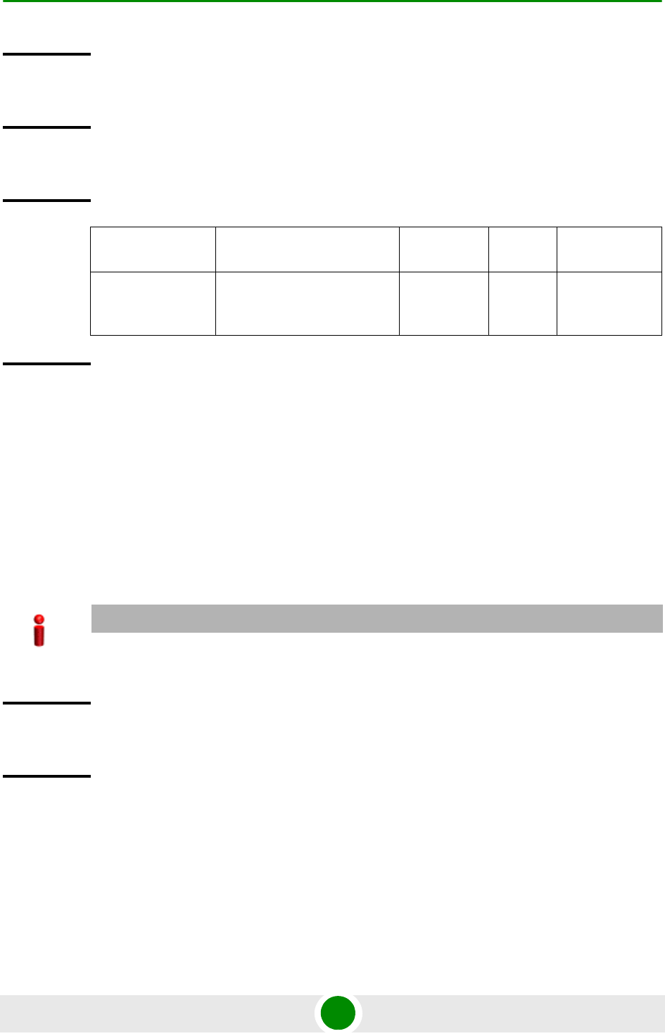
Chapter 3 - Operation and Administration of the Macro BTS NPU Configuration
4Motion 183 System Manual
3.4.8.1.6 Displaying Configuration Information for a Class-map
Run the following command to view the configuration information for a class-map:
npu# show class-map [<class-map-num(1-65535)>]
Specify the class-map number if you want to view configuration information for a
specific class-map. If you do not specify the class-map number, configuration
information for all class-maps is displayed.
Command
Syntax
npu(config)# no class-map <class-map-number(1-65535)>
Privilege
Level
10
Syntax
Description Parameter Description Presence Default
Value
Possible
Values
<class-map-numb
er(1-65535)>
Indicates the identifier of the
QoS class-map number to be
deleted.
Mandatory N/A 1-65535
Command
Modes
Global configuration mode
IMPORTANT
An error may occur if you specify a class-map number that does not exist or is not within the range,
1-65535.
Command
Syntax
npu# show class-map [<class-map-num(1-65535)>]
Privilege
Level
1

Chapter 3 - Operation and Administration of the Macro BTS NPU Configuration
4Motion 184 System Manual
3.4.8.2 Managing QoS Classification Rules
QoS classification rules classify packets into flows, based on the following
parameters:
IP address of the host originating the traffic (the IP address assigned to the
bearer, internal-management or external-management interface)
Layer 3 protocol indicating either TCP or UDP
Layer 4-source port for the application that needs to be marked (for example,
FTP, Telnet, SNMP, MIP, or RADIUS)
A class-map can be associated with each flow to define separate DSCP and/or
VLAN priority bits for QoS handling of each flow.
1Enable the ACL configuration mode for ACL 199 (refer to Section 3.4.8.2.1).
Syntax
Description Parameter Description Presence Default
Value
Possible
Values
[<class-map-num(
1-65535)>]
Indicates the identifier of the
class-map for which
configuration information is to
be displayed. Do not specify a
value for this parameter if you
want to view the configuration
information for all class-maps.
Optional N/A 1-65535
Display
Format (for
each
class-map if
requested
for all
class-maps)
Class map <class map number>
----------------------------------------------
CoS Value : <value>
DSCP Value : <value>
Command
Modes
Global command mode
To configure a QoS classification rule:

Chapter 3 - Operation and Administration of the Macro BTS NPU Configuration
4Motion 185 System Manual
2You can now:
»Configure one or more QoS classification rules (refer to Section 3.4.8.2.2)
»Delete one or more QoS classification rules (refer to Section 3.4.8.2.3)
»Terminate the ACL configuration mode (refer to Section 3.4.8.2.4)
You can, at any time, enable/disable QoS marking (refer to Section 3.4.8.3) or
view the configuration information for ACL 199 (refer to Section 3.4.8.4).
3.4.8.2.1 Enabling the ACL Configuration Mode for ACL 199
To configure QoS classification rules for host-originating traffic, first enable the
extended ACL 199 configuration mode.
Run the following command to enable the extended ACL configuration mode for
ACL 199.
npu(config)# ip access-list {standard <access-list-number (1-99)> |
extended <access-list-number (100-199)>} [name<string>]
After you enable the ACL 199 configuration mode, you can configure one or
several QoS classification rules, and associate them with the appropriate
class-maps.
IMPORTANT
QoS classification rules can be associated only with ACL 199.
IMPORTANT
QoS classification rules can be added only to extended ACL 199
Command
Syntax
npu(config)# ip access-list {standard <access-list-number (1-99)> | extended <access-list-number
(100-199)>} [name <string>]
Privilege
Level
10

Chapter 3 - Operation and Administration of the Macro BTS NPU Configuration
4Motion 186 System Manual
3.4.8.2.2 Configuring a QoS Classification Rule
You can configure the QoS classification rules for the ACL with respect the
following parameters:
Source IP address for the host-originating application traffic
Application protocol (TCP or UDP)
L4 source port of the application traffic
QoS class-map identifier
By default, there are 8 pre-configured QoS classification rules associated with the
8 pre-configured QoS class-maps:
Syntax
Description Parameter Description Presence Default
Value
Possible
Values
extended
<access-list-numb
er (100-199)>
Indicates the identifier of the
extended ACL for which the
ACL configuration mode is to
be enabled. You must specify
199 to enable configuration of
QoS classification rules.
Mandatory N/A 199
[name <string>] Indicates the name of the
ACL for which the ACL
configuration mode is to be
enabled.
Note: If you do not specify the
ACL name, the ACL number
is used as the default ACL
name.
Optional N/A String (upto 20
characters)
Command
Modes
Global configuration mode
Table 3-15: Pre-Configured QoS Classification Rules and Class-Maps
IP Interface Type of Traffic Protocol Source
Port Class
Map DSCP 802.1p
Bearer RADIUS UDP 1812 1 7 7

Chapter 3 - Operation and Administration of the Macro BTS NPU Configuration
4Motion 187 System Manual
After configuring QoS classification rules for this ACL, enable QoS marking for
this ACL. By default, QoS marking is disabled. For details, refer to Section 3.4.8.3.
Run the following command to configure a QoS classification rule for this ACL:
npu(config-ext-nacl)# qos-mark {{host <src-ip-address>} {{tcp |
udp} srcport <short (1-65535)>} qosclassifier <short (1-65535)>}
When you execute this command, a new QoS classification rule is added to the
ACL for which the configuration mode is enabled.
Bearer MobileIP-Agent UDP 434 2 7 7
Bearer WiMAX ASN
Control Plane
Protocol
UDP 2231 3 7 7
Internal-Management OBSAI message
exchange
between NPU
and AU
UDP 10009 4 0 0
Internal-Management Trivial File
Transfer Protocol
UDP 69 5 0 0
External-Management Telnet TCP 23 6 0 0
External-Management SSH Remote
Login Protocol
TCP 22 7 0 0
External-Management SNMP UDP 161 8 0 0
IMPORTANT
An error may occur if:
You have specified a source port that is not within the range, 1-65535.
The host IP address or class-map identifier that you have specified do not exist.
Command
Syntax
npu(config-ext-nacl)# qos-mark {{host <src-ip-address>} {{tcp | udp} srcport <short (1-65535)>}
qosclassifier <short (1-65535)>}
Privilege
Level
10
Table 3-15: Pre-Configured QoS Classification Rules and Class-Maps
IP Interface Type of Traffic Protocol Source
Port Class
Map DSCP 802.1p

Chapter 3 - Operation and Administration of the Macro BTS NPU Configuration
4Motion 188 System Manual
3.4.8.2.3 Deleting a QoS Classification Rule
To delete a QoS classification rule for an ACL, run the following command:
npu(config-ext-nacl)# no qos-mark {{host <src-ip-address>} {{tcp |
udp} srcport <short (1-65535)>} qosclassifier <short (1-65535)>}
Syntax
Description Parameter Description Presence Default
Value
Possible
Values
{host
<src-ip-address>}
Indicates the IP address of
the host interface that
generates the traffic for which
this classification rule is to be
configured. Specify the IP
address that you have
assigned to the
internal-management,
external-management,
local-management or bearer
IP interface.
Mandatory N/A Valid IP
address
(assigned to
the
internal-manag
ement,
external-mana
gement,
local-managem
ent or bearer IP
interface)
{tcp | udp} Indicates the transport
protocol.
Mandatory N/A tcp
udp
srcport <short
(1-65535)>
Indicates the source port
number of the application
traffic for which this QoS
classification rule is to be
applied.
Mandatory N/A 1-65535
qosclassifier
<class-map-numb
er (1-65535)>
Indicates the identifier of the
QoS class-map to be
associated with this
classification rule. For more
information about configuring
class-maps, refer
Section 3.4.8.1.
Mandatory N/A 1-65535
Command
Modes
Extended ACL configuration mode
IMPORTANT
You can delete a QoS classification rule only if the associated ACL is INACTIVE. For more
information, refer Section 3.4.10.3.

Chapter 3 - Operation and Administration of the Macro BTS NPU Configuration
4Motion 189 System Manual
When you execute this command, the QoS classification rule is deleted from the
ACL.
IMPORTANT
An error may occur if you specify a combination of parameters that do not match any of the existing
QoS classification rules.
Command
Syntax
npu(config-ext-nacl)# no qos-mark {{host <src-ip-address>} {{tcp | udp} srcport <short (1-65535)>}
qosclassifier <short (1-65535)>}
Privilege
Level
10
Syntax
Description Parameter Description Presence Default
Value
Possible
Values
[host
<src-ip-address>]
Indicates the IP address of
the host interface that
generates the traffic for which
this classification rule is to be
deleted.
Mandatory N/A Valid IP
address
(assigned to
the
internal-manag
ement,
external-mana
gement or
bearer IP
interface)
{tcp | udp} Indicates the transport
protocol.
Mandatory N/A tcp
udp
srcport <short
(1-65535)>
Indicates the source port
number of the application
traffic for which this QoS
classification rule is to be
deleted.
Mandatory N/A 1-65535
qosclassifier
<class-map-numb
er (1-65535)>
Indicates the identifier of the
QoS class-map associated
with the classification rule to
be deleted. For more
information about
class-maps, refer
Section 3.4.8.1.
Mandatory N/A 1-65535
Chapter 3 - Operation and Administration of the Macro BTS NPU Configuration
4Motion 190 System Manual
3.4.8.2.4 Terminating the ACL Configuration Mode
To terminate the ACL configuration mode, run the following command:
npu(config-ext-nacl) # exit
3.4.8.3 Enabling/Disabling QoS Marking for ACL 199
You can enable/disable the QoS marking for the ACL. The class-map is applied on
traffic matching a QoS classification rule only after you enable the QoS marking
for the ACL).
Run the following command to enable/disable the QoS marking for the specified
ACL:
npu(config)# set qos {enable | disable} 199
Command
Modes
Extended ACL configuration mode
Command
Syntax
npu(config-ext-nacl) # exit
Privilege
Level
10
Command
Modes
Extended ACL configuration mode
NOTE
If you want to modify a QoS class-map, first disable the QoS marking rules for the associated ACL.
By default, QoS marking is disabled for the ACL.
Command
Syntax
npu(config)# set qos {enable | disable} 199
Privilege
Level
10

Chapter 3 - Operation and Administration of the Macro BTS NPU Configuration
4Motion 191 System Manual
3.4.8.4 Displaying ACL 199 Configuration Information
Run the following command to display the configuration information for ACL 199:
npu# show access-lists [{199 | <access-list-199-name}]
Syntax
Description Parameter Description Presence Default
Value
Possible
Values
{enable | disable} Indicates whether QoS
marking should be enabled or
disabled for a specific ACL.
Mandatory disable enable
disable
199 Indicates the identifier of the
ACL for which the QoS
marking is to be activated.
You must specify 199.
Mandatory N/A 199
Command
Modes
Global configuration mode
IMPORTANT
An error may occur if the ACL name you have specified does not exist.
Command
Syntax
npu# show access-lists [199| <access-list-199-name}]
Privilege
Level
1
Syntax
Description Parameter Description Presence Default
Value
Possible
Values
[199 |
<access-list-199-n
ame}]
To view configuration
information for ACL 199,
specify 199 or the name
configured for this ACL.
Mandatory
for viewing
information
for ACL 199.
N/A 199
String; the
name
configured
for ACL
199.

Chapter 3 - Operation and Administration of the Macro BTS NPU Configuration
4Motion 192 System Manual
3.4.9 Configuring Static Routes
Using the CLI, you can configure the static routes for traffic originating from the
NPU. For each static route, you can configure the destination IP address, address
mask, and the next hop IP address. The following are the types of traffic
originating from the NPU:
R4/R6 control traffic
R3 control traffic such as RADIUS or MIP
NMS traffic
This section describes the commands for:
“Adding a Static Route” on page 193
“Deleting a Static Route” on page 194
Display
Format
(Standard)
Extended IP Access List 199
Access List Name(Alias) : 199
Interface List : NIL
Status : <Active|Inactive>
Admin-Status : <Up|Down>
Filter Protocol Type : <UDP|TCP>
Source IP address : <IP address>
Filter Source Port : <value>
Rule Action : QoS Marking
QoS Classifier ID : <value>
Marking rule status : <ACTIVE|INACTIVE>
...............
Command
Modes
Global command mode
Chapter 3 - Operation and Administration of the Macro BTS NPU Configuration
4Motion 193 System Manual
“Displaying the IP Routing Table” on page 195
There are four automatically created static route with the IP addresses of the
directly connected Bearer, External Management, Local Management and Internal
Management interfaces (the IP address of the Internal Management interface is set
to 10.0.0.254. Note that availability of certain interfaces depend on the
connectivity mode). These routes cannot be modified or deleted.
In addition, the default “Any Destination” entry with Destination 0.0.0.0 and
Mask 0.0.0.0 may be created. The Next Hop IP address of this route must be in
the same subnet with one of the NPU IP interfaces according to specific network
topology and needs.
3.4.9.1 Adding a Static Route
To add a static route, run the following command:
npu(config)# ip route <ip_address> <ip_mask> <ip_nexthop>
For example, run the following command to add an entry for a static route with
the destination IP address, 11.0.0.2, and the address mask, 255.255.255.255,
and next-hop IP address, 192.168.10.1.
npu(config)# ip route 11.0.0.2 255.255.255.255 192.168.10.1
NOTE
Refer to Section 3.4.9.3 to display the IP routing table.
IMPORTANT
An error may occur if:
The IP address, address mask or the next-hop IP address are invalid.
A route with the parameters that you have specified already exists.
The IP address that you have specified is being used for another interface.
The next-hop IP address that you have specified is either unreachable or is down.
Command
Syntax
npu(config)# ip route <ip_address> <ip_mask> <ip_nexthop>

Chapter 3 - Operation and Administration of the Macro BTS NPU Configuration
4Motion 194 System Manual
3.4.9.2 Deleting a Static Route
To delete a static route, run the following command:
npu(config)# no ip route <ip_address> <ip_mask> <ip_nexthop>
For example, run the following command to delete an entry for a static route with
the destination IP address, 11.0.0.2, and the address mask, 255.255.255.255,
and next-hop IP address, 192.168.10.1.
npu(config)# no ip route 11.0.0.2 255.255.255.255 192.168.10.1
Privilege
Level
10
Syntax
Description Parameter Description Presence Default
Value
Possible
Values
<ip_address> Indicates the destination host
or network IP address, for
which the route is to be
added.
Mandatory N/A Valid IP
address
<ip_mask> Indicates the address mask
for the static route to be
added.
Mandatory N/A Valid address
mask
<ip_nexthop> Indicates the next hop IP
address, for the route to be
added. Must be in the subnet
of one of the NPU IP
interfaces.
Mandatory N/A Valid IP
address
Command
Modes
Global configuration mode
NOTE
Kernel route is added automatically for default gateway network address of service interface of
VLAN type when service interface is attached to a service group and vlan enable is set for the
service group. This route is deleted when vlan is disabled for service group.
Also kernel route is added automatically for relay server IP address when service interface of type
VLAN is attached to a service group and vlan enable is set for the service group. This route is
deleted when vlan is disabled for the service group.
These routes are not displayed by the "show ip route" command.

Chapter 3 - Operation and Administration of the Macro BTS NPU Configuration
4Motion 195 System Manual
3.4.9.3 Displaying the IP Routing Table
To display the IP routing table, run the following command:
npu# show ip route
IMPORTANT
An error may occur if a route matching the specified parameters does not exist.
Command
Syntax
npu(config)# no ip route <ip_address> <ip_mask> <ip_nexthop>
Privilege
Level
10
Syntax
Description Parameter Description Presence Default
Value
Possible
Values
<ip_address> Indicates the destination host
or network IP address, for
which the route is to be
deleted.
Mandatory N/A Valid IP
address
<ip_mask> Indicates the address mask
for the static route to be
deleted.
Mandatory N/A Valid address
mask
<ip_nexthop> Indicates the next hop IP
address, for the route to be
deleted.
Mandatory N/A Valid IP
address
Command
Modes
Global configuration mode
NOTE
IP routes connected to an interface that is shut down are not displayed.
Command
Syntax
npu(config)# show ip route

Chapter 3 - Operation and Administration of the Macro BTS NPU Configuration
4Motion 196 System Manual
3.4.10 Configuring ACLs
ACLs are applied on traffic received from the NPU physical interfaces (DATA,
MGMT or CSCD ports), and destined towards the following virtual interfaces:
AUs
NPU
By default, all traffic destined towards the AUs is denied. Several default ACLs are
created automatically to allow some restricted traffic towards the NPU. These ACL
rules are applied automatically at the time of NPU startup or upon a change of IP
address of various interfaces. You can use the CLI to configure additional ACLs for
permitting or denying specific traffic destined towards the NPU or AUs.
You can create the following types of ACLs:
Standard: Allows you to filter traffic based on the source and destination IP
addresses.
Extended: Allows you to filter traffic based on the source and destination IP
addresses, source and destination ports, and protocol.
Privilege
Level
1
Display
Format
<IP address/mask> is directly connected
<IP address/mask> is directly connected
<IP address/mask> is directly connected
<IP address/mask> via <Next-hop IP address>
<IP address/mask> via <Next-hop IP address>
<IP address/mask> via <Next-hop IP address>
<IP address/mask> via <Next-hop IP address>
<IP address/mask> via <Next-hop IP address>
Command
Modes
Global command mode

Chapter 3 - Operation and Administration of the Macro BTS NPU Configuration
4Motion 197 System Manual
You can create the following types of rules for an ACL:
Permit: Indicates that traffic matching the filter criteria is allowed to reach the
NPU or AUs.
Deny: Indicates that traffic matching the filter criteria is dropped, and not
allowed to reach the NPU or AUs.
You can configure multiple rules for each ACL; the priority for these rules is
applied with respect to the sequence in which these rules are configured. The first
configured rule is the first one to be checked for a match, and so on. After you
configure an ACL, you can attach the ACL to either the NPU or the AUs or both
NPU and AUs.
All ACLs are either in the ACTIVE or INACTIVE state. The ACTIVE state indicates
that the ACL is attached to one or more interfaces; the INACTIVE state indicates
that the ACL is not attached to any interface. The priority of checking for a match
in active ACLs is applied with respect to the sequence in which these ACLs were
attached to the relevant interface. The first found match is applied. To change the
priories of ACLs you need to de-attach them from the relevant interface(s) and
then re-attach them in the required order.
To see the current order of ACLs attached to a certain interface, run the
command: npu# show interface npu-host | all-au.
By default, traffic towards the AUs is not restricted. This is implemented through
ACL 1 which is available by default. ACL 1 is attached to AUs, with Rule Action =
Permit, Source IP Address = Any and Destination IP Address = Any.
All the following automatically created standard default ACLs are attached to the
NPU virtual interface and include a single Permit rule:
IMPORTANT
You can use extended ACL 199 to configure QoS classification rules for classifying traffic originating
from the NPU into different flows. For details, refer “Configuring QoS Marking Rules” on
page 177).
Table 3-16: Default Standard ACLs
ACL Number Rule Action Source IP Address Destination IP Address
ACL 96 Permit Any Internal Management IP address
ACL 97 Permit Any External Management IP address
ACL 98 Permit Any Local Management IP address

Chapter 3 - Operation and Administration of the Macro BTS NPU Configuration
4Motion 198 System Manual
The default Extended ACL 186 attached to the NPU virtual interface includes the
following Permit rules allowing certain traffic towards the Bearer interface:
Additional Extended ACLs are created automatically for every Service Group that
is associated with a VLAN Service Interface and an enabled VLAN Service. Up to
10 ACLs, numbered ACL 187 to ACL 196, can be created, These automatically
created/deleted ACLs allow Ping and DHCP traffic on the DHCP Own IP Address
interface of the applicable VLAN service:
Table 3-17: Rules of Default ACL 186
Rule Action Source IP
Address Source
Port Destination IP
Address Destination
Port Protocol
Permit Any Any Bearer IP address Any ICMP (1)
Permit Any Any Bearer IP address 2231 (used
for WiMAX
ASN Control
Plane
Protocol)
UDP (17)
Permit Any Any Bearer IP address 1812-1813
(used for
RADIUS
Authenticatio
n and
Accounting)
UDP (17)
Permit Any Any Bearer IP address 69 (used for
TFTP)
UDP (17)
Permit Any Any Bearer IP address 1022-1023
(used for
software
download)
UDP (17)
Table 3-18: Rules of Default VLAN Service Interfaces ACL 187-196
Rule Action Source IP
Address Source
Port Destination IP
Address Destination
Port Protocol
Permit Any Any DHCP Own IP Address
defined for the
applicable Service
Group
Any ICMP (1)
Permit Any Any DHCP Own IP Address
defined for the
applicable Service
Group
67-68 (used
for DHCP
traffic)
UDP (17)
Chapter 3 - Operation and Administration of the Macro BTS NPU Configuration
4Motion 199 System Manual
This section describes the commands for:
“Configuring an ACL in the Standard/Extended Mode” on page 199
“Deleting an ACL” on page 221
“Attaching/De-attaching ACLs to/from an Interface” on page 223
“Displaying ACL Configuration Information” on page 226
3.4.10.1 Configuring an ACL in the Standard/Extended Mode
You can configure an ACL in either of the following modes:
Standard mode: Use this mode if you want to create Permit or Deny rules for
traffic based on source and destination IP addresses.
Extended mode: Use this mode if you want to create Permit or Deny rules
based on source and destination IP addresses, source and destination ports,
protocol.
1Enable the standard or extended ACL configuration mode (refer
Section 3.4.10.1.1).
2After you enter the ACL configuration mode, you can:
»Configure ACLs in the standard mode (refer Section 3.4.10.1.2).
»Configure ACLs in the extended mode (refer Section 3.4.10.1.3).
3Terminate the ACL configuration mode (refer Section 3.4.10.1.4).
4After you have configured the ACL, you can attach the ACL with the AUs or
NPU refer Section 3.4.10.3.
IMPORTANT
The default pre-configured and automatically created ACLs cannot be deleted and should not be
modified.
To configure an ACL:

Chapter 3 - Operation and Administration of the Macro BTS NPU Configuration
4Motion 200 System Manual
3.4.10.1.1 Enable the ACL Configuration Mode/Creating an ACL
To configure an ACL, first enable either of the following ACL configuration modes:
Standard
Extended
To apply this ACL to traffic destined towards the AUs or the NPU, you are required
to activate this ACL (for details refer Section 3.4.10.3).
Run the following command to enable the ACL configuration mode. You can also
use this command to create a new ACL.
npu(config)# ip access-list {standard <access-list-number (1-99)> |
extended <access-list-number (100-199)>}[name<string>]
When you run this command, the ACL configuration mode for the newly-created
ACL is automatically enabled. If the name is not specified when creating a new
ACL, the default name will be the specified ACL number.
For example, run the following command to create ACL 22 in the standard mode:
npu(config)# ip access-list standard 22
Standard ACL 22 will be created with the default name 22.
For example, run the following command to create ACL 111 in the extended mode,
with the name ACL-111:
npu(config)# ip access-list extended 111 ACL-111
After you create an ACL or enable the ACL configuration mode, you can
Configure the ACL in the standard mode (refer Section 3.4.10.1.2)
Configuring the ACL in the extended mode (refer Section 3.4.10.1.3)
IMPORTANT
ACL 199 is the default extended ACL that is pre-configured in the system, and is not attached to any
interface, that is, it is INACTIVE. However, ACL 199 is reserved for QoS classification rules. You
cannot configure Permit/Deny rules for ACL 199.
To view the default configuration information for ACL 199, you can run the following command:
npu# show access-lists 199
For details on using ACL 199 refer to Section 3.4.8.

Chapter 3 - Operation and Administration of the Macro BTS NPU Configuration
4Motion 201 System Manual
IMPORTANT
An error may occur if:·
You specify an invalid ACL number. The ACL number should be between 1 and 99 in the
standard mode, and between 100 and 199 in the extended mode.
The ACL name you have specified is already used for another ACL or is more than 20
characters.
Command
Syntax
npu(config)# ip access-list {standard <access-list-number (1-99)> | extended <access-list-number
(100-199)>}[name<string>]
Privilege
Level
10
Syntax
Description Parameter Description Presence Default
Value
Possible
Values
standard
<access-list-numb
er (1-99)> |
extended
<access-list-numb
er (100-199)>
Denotes the number of the
standard or extended ACL
that is to be created for which
the ACL configuration mode
is to be enabled. If you are
creating a new ACL, the ACL
configuration mode is
automatically enabled when
you execute this command.
Note: ACL 199 is reserved for
QoS classification rules and
cannot be used for creating
Permit/Deny rules.
Mandatory N/A standard
1-99
extended
(100-198)
[name<string>] Indicates the name of the
ACL to be created for which
the ACL configuration mode
is to be enabled.
Optional ACL
name
String (upto 20
characters)
Command
Modes
Global configuration mode

Chapter 3 - Operation and Administration of the Macro BTS NPU Configuration
4Motion 202 System Manual
3.4.10.1.2 Configuring ACLs in the Standard Mode
After you have enabled the standard ACL configuration mode, you can create or
delete the Permit/Deny rules for forwarding traffic from/to a particular
source/destination IP address.
This section describes the commands for:
“Creating a Permit/Deny Rule (Standard Mode)” on page 202
“Deleting a Permit/Deny Rule (Standard Mode)” on page 204
3.4.10.1.2.1 Creating a Permit/Deny Rule (Standard Mode)
Run the following commands to create the Permit/Deny rules for forwarding
traffic from/to a particular source/destination IP address:
npu(config-std-nacl)# permit {any | host <src-ip-address> |
<network-src-ip> <mask>} [{any | host <dest-ip-address> |
<network-dest-ip> <mask>}]
npu(config-std-nacl)# deny {any | host <src-ip-address> |
<network-src-ip> <mask>} [{any | host <dest-ip-address> |
<network-dest-ip> <mask>}]
The following table lists the parameters and their descriptions in these
commands.
IMPORTANT
You cannot create Permit or Deny rules for an ACL that is associated with a Qos marking rule. You
can either associate QoS marking rules or permit/deny rules with an ACL.
IMPORTANT
After you have configured the rules to be applied on an ACL, you can attach the ACL to the NPU or
AUs. The ACL enables filtering of traffic destined to these interfaces. For more information, refer to
Section 3.4.10.3.
IMPORTANT
In the above commands, it is mandatory to specify the source IP address for which the Permit/Deny
rule is to be created. If you do not specify the destination IP address/subnet mask, by default, traffic
to all destination IP addresses configured for the NPU is permitted/denied.

Chapter 3 - Operation and Administration of the Macro BTS NPU Configuration
4Motion 203 System Manual
Table 3-19: Parameters for Configuring Permit/Deny Rules in the Standard ACL Mode
Parameter Description Example
Source IP any Indicates that incoming traffic
from any source IP address is
permitted or denied.
npu(config-std-nacl)# permit any
npu(config-std-nacl)# deny any
host
<src-ip-addres
s>
Indicates that incoming traffic
from a specific source IP
address is permitted or denied.
npu(config-std-nacl)# permit host
1.1.1.1
npu(config-std-nacl)# deny host
1.1.1.1
<network-src-i
p> <mask>
Indicates that incoming traffic is
to be permitted or denied for a
particular subnet.
npu(config-std-nacl)# permit 1.1.1.0
255.255.255.0
npu(config-std-nacl)# deny 1.1.1.0
255.255.255.0
Destination
IP address
any Indicates that traffic destined to
all NPU IP addresses is
permitted or denied.
npu(config-std-nacl)# permit host
1.1.1.1 any
npu(config-std-nacl)# deny host
1.1.1.1 any
host
<src-ip-addres
s>
Indicates that traffic destined to
a specific destination IP address
is permitted or denied.
npu(config-std-nacl)# permit any
host 1.1.1.1
npu(config-std-nacl)# deny any host
1.1.1.1
<network-src-i
p> <mask>
Indicates that traffic destined to
a particular subnet is to be
permitted or denied.
npu(config-std-nacl)# permit any
1.1.1.0 255.255.255.0
npu(config-std-nacl)# deny any
1.1.1.0 255.255.255.0
Command
Syntax
npu(config-std-nacl)# permit {any | host <src-ip-address> | <network-src-ip> <mask>} [{any |
host <dest-ip-address> | <network-dest-ip> <mask>}]
npu(config-std-nacl)# deny { any | host <src-ip-address> | <network-src-ip> <mask> } [ { any |
host <dest-ip-address> | <network-dest-ip> <mask> } ]
Syntax
Description Parameter Description Presence Default
Value
Possible
Values
{ any | host
<src-ip-address> |
<network-src-ip>
<mask> }
Indicates the source IP
address/subnet for which
incoming traffic is
permitted/denied.
Mandatory N/A For details,
refer
Table 3-19

Chapter 3 - Operation and Administration of the Macro BTS NPU Configuration
4Motion 204 System Manual
3.4.10.1.2.2 Deleting a Permit/Deny Rule (Standard Mode)
Run the following commands to delete the Permit/Deny rule for incoming traffic
from/to a specific IP address/subnet.
npu(config-std-nacl)# no permit {any | host <src-ip-address> |
<network-src-ip> <mask>} [{any | host <dest-ip-address> |
<network-dest-ip> <mask>}]
npu(config-std-nacl)# no deny {any | host <src-ip-address> |
<network-src-ip> <mask>} [{any | host <dest-ip-address> |
<network-dest-ip> <mask>}]
[ { any | host
<dest-ip-address>
| <network-dest-ip>
<mask> } ]
Indicates the destination IP
address/subnet for which
traffic is permitted/denied
Optional any For details,
refer
Table 3-19
Command
Modes
Standard ACL configuration mode
Command
Syntax
npu(config-std-nacl)# no permit { any | host <src-ip-address> | <network-src-ip> <mask> } [ {
any | host <dest-ip-address> | <network-dest-ip> <mask> } ]
npu(config-std-nacl)# no deny { any | host <src-ip-address> | <network-src-ip> <mask> } [ { any
| host <dest-ip-address> | <network-dest-ip> <mask> } ]
Privilege
Level
10
Syntax
Description Parameter Description Presence Default
Value
Possible
Values
{ any | host
<src-ip-address> |
<network-src-ip>
<mask> }
Indicates the source IP
address/subnet for which the
Permit/Deny rule is to be
deleted.
Mandatory N/A For details,
refer
Table 3-19
[ { any | host
<dest-ip-address>
| <network-dest-ip>
<mask> } ]
Indicates the destination IP
address/subnet for which the
Permit/Deny rule is to be
deleted.
Optional any For details,
refer
Table 3-19

Chapter 3 - Operation and Administration of the Macro BTS NPU Configuration
4Motion 205 System Manual
3.4.10.1.3 Configuring ACLs in the Extended Mode
After you have enabled the extended ACL configuration mode, you can create
Permit/Deny rules based on source/destination IP address, protocol and
source/destination port numbers.
This section describes the commands to be used for:
“Configuring Permit/Deny Rules from/to a Specific Protocol and
Source/Destination IP Addresses” on page 205
“Configuring Permit/Deny Rules for TCP/UDP Traffic” on page 210
“Configuring Permit/Deny Rules for ICMP Traffic” on page 217
3.4.10.1.3.1 Configuring Permit/Deny Rules from/to a Specific Protocol and
Source/Destination IP Addresses
After you have created an ACL, you can configure Permit/Deny rules to be applied
for traffic from/to a particular source/destination IP address/subnet, with
respect to a specific protocol.
This section describes the commands to be used for:
“Creating a Permit/Deny Rule for Specific Protocols/IP Addresses (Extended
Mode)” on page 206
Command
Modes
Standard ACL configuration mode
IMPORTANT
You cannot create Permit or Deny rules for an ACL that is associated with a Qos marking rule. You
can either associate QoS marking rules or permit/deny rules with an ACL.
IMPORTANT
After you have configured the rules to be applied on an ACL, you can attach the ACL to the NPU or
AUs. The ACL enables filtering of traffic destined to these interfaces. For more information, refer to
Section 3.4.10.3.
IMPORTANT
You cannot configure Permit or Deny rules for an ACL that is associated with a Qos marking rule.
You can either associate QoS marking rules or permit/deny rules with an ACL.

Chapter 3 - Operation and Administration of the Macro BTS NPU Configuration
4Motion 206 System Manual
“Deleting a Permit/Deny Rule for Specific Protocols/IP Addresses (Extended
Mode)” on page 209
3.4.10.1.3.1.1Creating a Permit/Deny Rule for Specific Protocols/IP Addresses
(Extended Mode)
You can create the Permit or Deny rule for traffic from/to a source/ destination IP
address/subnet with respect to the following protocols:
IP
OSPF
Protocol Independent Multicast (PIM)
Any other protocol
Run the following commands to create the Permit/Deny rule for traffic from and to
a specific IP address/subnet for a particular protocol:
npu(config-ext-nacl)# permit {ip | ospf | pim | <protocol-type
(1-255)>} {any | host <src-ip-address> | <src-ip-address> <mask>}
{any | host <dest-ip-address> | <dest-ip-address> <mask>}
npu(config-ext-nacl)# deny {ip | ospf | pim | <protocol-type
(1-255)>} {any | host <src-ip-address> | <src-ip-address> <mask>}
{any | host <dest-ip-address> | <dest-ip-address> <mask>}
In the above commands, it is mandatory to specify the protocol and source IP
address for which the Permit/Deny rule is to be created. If you do not specify the
destination IP address/subnet mask, by default, traffic to all destination IP
addresses is permitted/denied.
The following table lists the parameters and their descriptions in these
commands:

Chapter 3 - Operation and Administration of the Macro BTS NPU Configuration
4Motion 207 System Manual
Table 3-20: Parameters for Configuring Permit/Deny Rules for Traffic from/to Specific IP Addresses
Parameter Description Example
Protocol ip Indicates that the Permit/Deny
rule to be created is to be
applied for the IP-in-IP packets.
npu(config-ext-nacl)# permit ip any
ospf Indicates that the Permit/Deny
rule to be created is to be
applied to OSPF packets.
npu(config-ext-nacl)# permit ospf
any
pim Indicates that the Permit/Deny
rule to be created is to be
applied to the PIM packets.
npu(config-ext-nacl)# permit pim any
<protocol-type
(1-255)>
Indicates that the Permit/Deny
rule to be created is to be
applied to traffic from/to any
protocol (including IP, OSPF,
PIM). Use standard IANA values
to specify the values of these
protocols
npu(config-ext-nacl)# permit 11 any
Source IP
address
any Indicates that incoming traffic
from any source IP address is
permitted or denied.
npu(config-std-nacl)# permit ip any
npu(config-std-nacl)# deny ip any
host
<src-ip-addres
s>
Indicates that incoming traffic
from a specific source IP
address is permitted or denied.
npu(config-std-nacl)# permit ip host
1.1.1.1
npu(config-std-nacl)# deny ip host
1.1.1.1
<network-src-i
p> <mask>
Indicates that incoming traffic is
to be permitted or denied for a
particular source IP address and
subnet mask.
npu(config-std-nacl)# permit ip
1.1.1.0 255.255.255.0
npu(config-std-nacl)# deny ip
1.1.1.0 255.255.255.0

Chapter 3 - Operation and Administration of the Macro BTS NPU Configuration
4Motion 208 System Manual
Destination
IP address
any Indicates that traffic to any
destination IP address is
permitted or denied. any is the
default destination IP address.
npu(config-std-nacl)# permit ip host
1.1.1.1 any
npu(config-std-nacl)# deny ip host
1.1.1.1 any
host
<dst-ip-addres
s>
Indicates that traffic destined to
a specific destination IP address
is permitted or denied.
npu(config-std-nacl)# permit ip any
host 1.1.1.1
npu(config-std-nacl)# deny ip any
host 1.1.1.1
<network-dst-i
p> <mask>
Indicates that traffic destined to
a particular subnet is to be
permitted or denied.
npu(config-std-nacl)# permit ip any
1.1.1.0 255.255.255.0
npu(config-std-nacl)# deny ip any
1.1.1.0 255.255.255.0
Command
Syntax
npu(config-ext-nacl)# permit { ip | ospf | pim | <protocol-type (1-255)>} { any | host
<src-ip-address> | <src-ip-address> <mask> } { any | host <dest-ip-addresq> | <dest-ip-address>
<mask> }
npu(config-ext-nacl)# deny { ip | ospf | pim | <protocol-type (1-255)>} { any | host <src-ip-address>
| <src-ip-address> <mask> } { any | host <dest-ip-addresq> | <dest-ip-address> <mask> }
Privilege
Level
10
Syntax
Description Parameter Description Presence Default
Value
Possible
Values
{ ip | ospf | pim |
<protocol-type
(1-255)>}
Indicates the type of protocol
for which incoming traffic is
permitted.
Mandatory N/A For details,
refer
Table 3-20
{ any | host
<src-ip-address> |
<src-ip-address>
<mask> }
Indicates the source IP
address/subnet for which
incoming traffic is
permitted/denied.
Mandatory N/A For details,
refer
Table 3-20
{ any | host
<dest-ip-addresq>
|
<dest-ip-address>
<mask> }
Indicates the destination IP
address/subnet for which
traffic is permitted/denied
Optional any For details,
refer
Table 3-20
Table 3-20: Parameters for Configuring Permit/Deny Rules for Traffic from/to Specific IP Addresses
Parameter Description Example

Chapter 3 - Operation and Administration of the Macro BTS NPU Configuration
4Motion 209 System Manual
3.4.10.1.3.1.2Deleting a Permit/Deny Rule for Specific Protocols/IP Addresses
(Extended Mode)
Run the following commands to delete the Permit/Deny rule for traffic from to a
specific IP address/subnet for a particular protocol:
npu(config-ext-nacl)# no permit {ip | ospf | pim | <protocol-type
(1-255)>} {any | host <src-ip-address> | <src-ip-address> <mask>}
{any | host <dest-ip-address> | <dest-ip-address> <mask>}
npu(config-ext-nacl)# no deny {ip | ospf | pim | <protocol-type
(1-255)>} {any | host <src-ip-address> | <src-ip-address> <mask>}
{any | host <dest-ip-address> | <dest-ip-address> <mask>}
Command
Modes
Extended ACL configuration mode
Command
Syntax
npu(config-ext-nacl)# no permit { ip | ospf | pim | <protocol-type (1-255)>} { any | host
<src-ip-address> | <src-ip-address> <mask> } { any | host <dest-ip-addresq> | <dest-ip-address>
<mask> }
npu(config-ext-nacl)# no deny { ip | ospf | pim | <protocol-type (1-255)>} { any | host
<src-ip-address> | <src-ip-address> <mask> } { any | host <dest-ip-addresq> | <dest-ip-address>
<mask> }
Privilege
Level
10
Syntax
Description Parameter Description Presence Default
Value
Possible
Values
{ ip | ospf | pim |
<protocol-type
(1-255)>}
Indicates the type of protocol
for which the Permit/Deny
rule is to be deleted.
Mandatory N/A For details,
refer
Table 3-20
{ any | host
<src-ip-address> |
<src-ip-address>
<mask> }
Indicates the source IP
address/subnet for which the
Permit/Deny rule is to be
deleted.
Mandatory N/A For details,
refer
Table 3-20

Chapter 3 - Operation and Administration of the Macro BTS NPU Configuration
4Motion 210 System Manual
3.4.10.1.3.2 Configuring Permit/Deny Rules for TCP/UDP Traffic
After you have created an ACL, you can configure Permit/Deny rules for TCP and
UDP traffic from/to specific source and destination IP address and port.
This section describes the commands to be used for:
“Creating a Permit/Deny Rule for TCP/UDP Traffic (Extended Mode)” on
page 210
“Deleting a Permit/Deny Rule for TCP/UDP Traffic (Extended Mode)” on
page 215
3.4.10.1.3.2.1Creating a Permit/Deny Rule for TCP/UDP Traffic (Extended Mode)
Run the following commands to specify the Permit rule for TCP/UDP traffic
from/to a specific source/destination IP address/port:
npu(config-ext-nacl)# permit tcp {any | host <src-ip-address> |
<src-ip-address> <src-mask>} [{gt <port-number (1-65535)> | lt
<port-number (1-65535)> |eq <port-number (1-65535)> | range
<port-number (1-65535)> <port-number (1-65535)>}] {any | host
<dest-ip-address> | <dest-ip-address> <dest-mask>} {gt <port-number
(1-65535)> | lt <port-number (1-65535)> | eq <port-number
(1-65535)> | range <port-number (1-65535)> <port-number
(1-65535)>}]
npu(config-ext-nacl)# permit udp {any | host <src-ip-address> |
<src-ip-address> <src-mask>} [{gt <port-number (1-65535)> | lt
<port-number (1-65535)> |eq <port-number (1-65535)> | range
<port-number (1-65535)> <port-number (1-65535)>}] {any | host
{ any | host
<dest-ip-addresq>
|
<dest-ip-address>
<mask> }
Indicates the destination IP
address/subnet for which the
Permit/Deny rule is to be
deleted.
Optional any For details,
refer
Table 3-20
Command
Modes
Extended ACL configuration mode
IMPORTANT
You cannot configure Permit or Deny rules for an ACL that is associated with a Qos marking rule.
You can either associate QoS marking rules or permit/deny rules with an ACL.

Chapter 3 - Operation and Administration of the Macro BTS NPU Configuration
4Motion 211 System Manual
<dest-ip-address> | <dest-ip-address> <dest-mask>} {gt <port-number
(1-65535)> | lt <port-number (1-65535)> | eq <port-number
(1-65535)> | range <port-number (1-65535)> <port-number
(1-65535)>}]
Run the following commands to specify the Deny rule for TCP/UDP traffic from/to
a specific source/destination IP address/port:
npu(config-ext-nacl)# deny tcp {any | host <src-ip-address> |
<src-ip-address> <src-mask>} [{gt <port-number (1-65535)> | lt
<port-number (1-65535)> |eq <port-number (1-65535)> | range
<port-number (1-65535)> <port-number (1-65535)>}] {any | host
<dest-ip-address> | <dest-ip-address> <dest-mask>} {gt <port-number
(1-65535)> | lt <port-number (1-65535)> | eq <port-number
(1-65535)> | range <port-number (1-65535)> <port-number
(1-65535)>}]
npu(config-ext-nacl)# deny udp {any | host <src-ip-address> |
<src-ip-address> <src-mask>} [{gt <port-number (1-65535)> | lt
<port-number (1-65535)> |eq <port-number (1-65535)> | range
<port-number (1-65535)> <port-number (1-65535)>}] {any | host
<dest-ip-address> | <dest-ip-address> <dest-mask>} {gt <port-number
(1-65535)> | lt <port-number (1-65535)> | eq <port-number
(1-65535)> | range <port-number (1-65535)> <port-number
(1-65535)>}]
In the above commands, it is mandatory to specify the source and destination IP
address for which the Permit/Deny rule is to be created.
The following table lists the parameters and their descriptions in these
commands:
IMPORTANT
To increase the granularity of the Permit/Deny rule you are creating, specify the source and
destination port numbers for the source and destination IP addresses.

Chapter 3 - Operation and Administration of the Macro BTS NPU Configuration
4Motion 212 System Manual
Table 3-21: Parameters for Configuring Permit/Deny Rules for TCP/UDP Traffic
Parameter Description Example
Source IP
address
any Indicates that incoming
TCP/UDP traffic from any source
IP address is permitted or
denied.
npu(config-ext-nacl)# permit tcp any
any
npu(config-ext-nacl)# deny udp any
host
<src-ip-addres
s>
Indicates that incoming
TCP/UDP traffic from a specific
source IP address is permitted
or denied.
npu(config-ext-nacl)# permit tcp host
1.1.1.1 any
npu(config-ext-nacl)# deny udp host
1.1.1.1
<network-src-i
p> <mask>
Indicates that incoming
TCP/UDP traffic is to be
permitted or denied for a
particular subnet.
npu(config-ext-nacl)# permit tcp
1.1.1.0 255.255.255.0 any
npu(config-ext-nacl)# deny udp
1.1.1.0 255.255.255.0
Source port [{gt
<port-number
(1-65535)>
Indicates that incoming TCP/
UDP traffic is to be permitted or
denied from the source port for
which the port number is greater
than the value of this parameter.
npu(config-ext-nacl)# permit tcp
1.1.1.0 255.255.255.0 gt 1111
npu(config-ext-nacl)# deny udp host
1.1.1.1 gt 1010
[{lt
<port-number
(1-65535)>
Indicates that incoming TCP/
UDP traffic is to be permitted or
denied from the source port for
which the port number is less
than the value of this parameter.
npu(config-ext-nacl)# permit tcp
1.1.1.0 255.255.255.0 lt 1111
npu(config-ext-nacl)# deny udp host
1.1.1.1 lt 1010
[{eq
<port-number
(1-65535)>
Indicates that incoming TCP/
UDP traffic is to be permitted or
denied from the source port for
which the port number is equal
to the value of this parameter.
npu(config-ext-nacl)# permit tcp
1.1.1.0 255.255.255.0 eq 8080
npu(config-ext-nacl)# deny udp host
1.1.1.1 eq 4040
range
<port-number
(1-65535)>
<port-number
(1-65535)>}]
Indicates that incoming TCP/
UDP traffic is to be permitted or
denied from the source port for
which the port number is within
the range specified by this
parameter.
npu(config-ext-nacl)# permit tcp
1.1.1.0 255.255.255.0 range 1010
8080
npu(config-ext-nacl)# deny udp host
1.1.1.1 range 1010 4040

Chapter 3 - Operation and Administration of the Macro BTS NPU Configuration
4Motion 213 System Manual
Destination
IP address
any Indicates that TCP/UDP traffic to
all NPU interface IP addresses is
permitted or denied.
npu(config-ext-nacl)# permit tcp
1.1.1.1 host any
npu(config-ext-nacl)# deny udp any
any
host
<src-ip-addres
s>
Indicates that TCP/UDP traffic to
a specific NPU interface IP
address is permitted or denied.
npu(config-ext-nacl)# permit tcp any
host 1.1.1.1 host host 1.1.1.1
npu(config-ext-nacl)# deny udp any
host 1.1.1.1
<network-src-i
p> <mask>
Indicates that TCP/UDP traffic is
to be permitted or denied for a
particular NPU interface subnet.
npu(config-ext-nacl)# permit tcp any
host 1.1.1.0 255.255.255.0
npu(config-ext-nacl)# deny udp any
host 1.1.1.0 255.255.255.0
Destination
port
[{gt
<port-number
(1-65535)>
Indicates that TCP/ UDPtraffic is
to be permitted or denied to the
NPU interface source port for
which the port number is greater
than the value of this parameter.
npu(config-ext-nacl)# permit tcp host
1.1.1.1 host any gt 8080
npu(config-ext-nacl)# deny udp any
any
[{lt
<port-number
(1-65535)>
Indicates that TCP/ UDP traffic is
to be permitted or denied to the
NPU interface source port for
which the port number is less
than the value of this parameter.
npu(config-ext-nacl)# permit tcp host
1.1.1.0 255.255.255.0 any lt 1111
npu(config-ext-nacl)# deny udp any
host 1.1.1.1 lt 1010
[{eq
<port-number
(1-65535)>
Indicates that TCP/ UDP traffic is
to be permitted or denied to the
NPU interface source port for
which the port number is equal
to the value of this parameter.
npu(config-ext-nacl)# permit tcp any
1.1.1.0 255.255.255.0 eq 8080
npu(config-ext-nacl)# deny udp any
host 1.1.1.1 eq 4040
range
<port-number
(1-65535)>
<port-number
(1-65535)>}]
Indicates that TCP/ UDP traffic is
to be permitted or denied the
NPU interface source port for
which the port number is within
the range specified by this
parameter.
npu(config-ext-nacl)# permit tcp host
1.1.1.1 host 1.1.1.0 255.255.255.0
range 1010 8080
npu(config-ext-nacl)# deny udp host
1.1.1.1 any range 1010 4040
Table 3-21: Parameters for Configuring Permit/Deny Rules for TCP/UDP Traffic
Parameter Description Example

Chapter 3 - Operation and Administration of the Macro BTS NPU Configuration
4Motion 214 System Manual
Command
Syntax
npu(config-ext-nacl)# deny tcp {any | host <src-ip-address> | <src-ip-address> <src-mask> } [{gt
<port-number (1-65535)> | lt <port-number (1-65535)> |eq <port-number (1-65535)> | range
<port-number (1-65535)> <port-number (1-65535)>}] {any | host <dest-ip-address> |
<dest-ip-address> <dest-mask>} {gt <port-number (1-65535)> | lt <port-number (1-65535)> | eq
<port-number (1-65535)> | range <port-number (1-65535)> <port-number (1-65535)>}]
npu(config-ext-nacl)# deny udp {any | host <src-ip-address> | <src-ip-address> <src-mask> } [{gt
<port-number (1-65535)> | lt <port-number (1-65535)> |eq <port-number (1-65535)> | range
<port-number (1-65535)> <port-number (1-65535)>}] {any | host <dest-ip-address> |
<dest-ip-address> <dest-mask>} {gt <port-number (1-65535)> | lt <port-number (1-65535)> | eq
<port-number (1-65535)> | range <port-number (1-65535)> <port-number (1-65535)>}]
Privilege
Level
10
Syntax
Description Parameter Description Presence Default
Value
Possible
Values
any | host
<src-ip-address> |
<src-ip-address>
<src-mask>
Indicates the source host for
which incoming TCP/UDP
traffic is permitted/denied.
Mandatory N/A For details,
refer
Table 3-21
[{gt <port-number
(1-65535)> | lt
<port-number
(1-65535)> |eq
<port-number
(1-65535)> | range
<port-number
(1-65535)>
<port-number
(1-65535)>}]
Indicates the source port from
which incoming TCP/UDP
traffic is permitted/denied.
Optional 0-65535 For details,
refer
Table 3-21
any | host
<dest-ip-address>
|
<dest-ip-address>
<dest-mask>
Indicates the destination IP
address/subnet for which
TCP/UDP traffic is
permitted/denied.
Mandatory N/A For details,
refer
Table 3-21

Chapter 3 - Operation and Administration of the Macro BTS NPU Configuration
4Motion 215 System Manual
3.4.10.1.3.2.2Deleting a Permit/Deny Rule for TCP/UDP Traffic (Extended Mode)
Run the following commands to delete a Permit rule for TCP/UDP traffic from/to a
specific IP address/port:
npu(config-ext-nacl)# no permit tcp {any | host <src-ip-address> |
<src-ip-address> <src-mask>} [{gt <port-number (1-65535)> | lt
<port-number (1-65535)> |eq <port-number (1-65535)> | range
<port-number (1-65535)> <port-number (1-65535)>}] {any | host
<dest-ip-address> | <dest-ip-address> <dest-mask>} {gt <port-number
(1-65535)> | lt <port-number (1-65535)> | eq <port-number
(1-65535)> | range <port-number (1-65535)> <port-number
(1-65535)>}]
npu(config-ext-nacl)# no permit udp {any | host <src-ip-address> |
<src-ip-address> <src-mask>} [{gt <port-number (1-65535)> | lt
<port-number (1-65535)> |eq <port-number (1-65535)> | range
<port-number (1-65535)> <port-number (1-65535)>}] {any | host
<dest-ip-address> | <dest-ip-address> <dest-mask>} {gt <port-number
(1-65535)> | lt <port-number (1-65535)> | eq <port-number
(1-65535)> | range <port-number (1-65535)> <port-number
(1-65535)>}]
Run the following commands to delete a Deny rule for TCP/UDP traffic from/to a
specific IP address/port:
npu(config-ext-nacl)# no deny tcp {any | host <src-ip-address> |
<src-ip-address> <src-mask>} [{gt <port-number (1-65535)> | lt
<port-number (1-65535)> |eq <port-number (1-65535)> | range
<port-number (1-65535)> <port-number (1-65535)>}] {any | host
<dest-ip-address> | <dest-ip-address> <dest-mask>} {gt <port-number
{gt <port-number
(1-65535)> | lt
<port-number
(1-65535)> | eq
<port-number
(1-65535)> | range
<port-number
(1-65535)>
<port-number
(1-65535)>}]
Indicates the destination port
to which TCP/UDP traffic is
permitted/denied.
Optional 0-65535 For details,
refer
Table 3-21
Command
Modes
Extended ACL configuration mode

Chapter 3 - Operation and Administration of the Macro BTS NPU Configuration
4Motion 216 System Manual
(1-65535)> | lt <port-number (1-65535)> | eq <port-number
(1-65535)> | range <port-number (1-65535)> <port-number
(1-65535)>}]
npu(config-ext-nacl)# no deny udp {any | host <src-ip-address> |
<src-ip-address> <src-mask>} [{gt <port-number (1-65535)> | lt
<port-number (1-65535)> |eq <port-number (1-65535)> | range
<port-number (1-65535)> <port-number (1-65535)>}] {any | host
<dest-ip-address> | <dest-ip-address> <dest-mask>} {gt <port-number
(1-65535)> | lt <port-number (1-65535)> | eq <port-number
(1-65535)> | range <port-number (1-65535)> <port-number
(1-65535)>}]
Command
Syntax (for
Permit Rule)
npu(config-ext-nacl)# no permit tcp {any | host <src-ip-address> | <src-ip-address> <src-mask>
} [{gt <port-number (1-65535)> | lt <port-number (1-65535)> |eq <port-number (1-65535)> | range
<port-number (1-65535)> <port-number (1-65535)>}] {any | host <dest-ip-address> |
<dest-ip-address> <dest-mask>} {gt <port-number (1-65535)> | lt <port-number (1-65535)> | eq
<port-number (1-65535)> | range <port-number (1-65535)> <port-number (1-65535)>}]
npu(config-ext-nacl)# no permit udp {any | host <src-ip-address> | <src-ip-address> <src-mask>
} [{gt <port-number (1-65535)> | lt <port-number (1-65535)> |eq <port-number (1-65535)> | range
<port-number (1-65535)> <port-number (1-65535)>}] {any | host <dest-ip-address> |
<dest-ip-address> <dest-mask>} {gt <port-number (1-65535)> | lt <port-number (1-65535)> | eq
<port-number (1-65535)> | range <port-number (1-65535)> <port-number (1-65535)>}]
Command
Syntax (for
Deny Rule)
npu(config-ext-nacl)# no deny tcp {any | host <src-ip-address> | <src-ip-address> <src-mask> }
[{gt <port-number (1-65535)> | lt <port-number (1-65535)> |eq <port-number (1-65535)> | range
<port-number (1-65535)> <port-number (1-65535)>}] {any | host <dest-ip-address> |
<dest-ip-address> <dest-mask>} {gt <port-number (1-65535)> | lt <port-number (1-65535)> | eq
<port-number (1-65535)> | range <port-number (1-65535)> <deny-number (1-65535)>}]
npu(config-ext-nacl)# no deny udp {any | host <src-ip-address> | <src-ip-address> <src-mask> }
[{gt <port-number (1-65535)> | lt <port-number (1-65535)> |eq <port-number (1-65535)> | range
<port-number (1-65535)> <port-number (1-65535)>}] {any | host <dest-ip-address> |
<dest-ip-address> <dest-mask>} {gt <port-number (1-65535)> | lt <port-number (1-65535)> | eq
<port-number (1-65535)> | range <port-number (1-65535)> <port-number (1-65535)>}]
Privilege
Level
10

Chapter 3 - Operation and Administration of the Macro BTS NPU Configuration
4Motion 217 System Manual
3.4.10.1.3.3 Configuring Permit/Deny Rules for ICMP Traffic
After you have created an ACL, you can configure Permit/Deny rules for ICMP
traffic from/to specific a source and destination IP address/subnet.
Syntax
Description Parameter Description Presence Default
Value
Possible
Values
any | host
<src-ip-address> |
<src-ip-address>
<src-mask>
Indicates the source host for
which the Permit/Deny rule
for incoming TCP/UDP traffic
is to be deleted.
Mandatory N/A For details,
refer
Table 3-21
[{gt <port-number
(1-65535)> | lt
<port-number
(1-65535)> |eq
<port-number
(1-65535)> | range
<port-number
(1-65535)>
<port-number
(1-65535)>}]
Indicates the source port for
which the Permit/Deny rule
for incoming TCP/UDP traffic
is to be deleted.
Optional 1-65535 For details,
refer
Table 3-21
any | host
<dest-ip-address>
|
<dest-ip-address>
<dest-mask>
Indicates the NPU IP
address/subnet for which the
Permit/Deny rule for
TCP/UDP traffic is to be
deleted.
Mandatory N/A For details,
refer
Table 3-21
[{gt <port-number
(1-65535)> | lt
<port-number
(1-65535)> |eq
<port-number
(1-65535)> | range
<port-number
(1-65535)>
<port-number
(1-65535)>}]
Indicates the NPU interface
port for which the
Permit/Deny rule for incoming
TCP/UDP traffic is to be
deleted.
Optional 1-65535 For details,
refer
Table 3-21
Command
Modes
Extended ACL configuration mode

Chapter 3 - Operation and Administration of the Macro BTS NPU Configuration
4Motion 218 System Manual
This section describes the commands to be used for:
“Creating a Permit/Deny Rule for ICMP Traffic (Extended Mode)” on page 218
“Deleting a Permit/Deny Rule for ICMP Traffic (Extended Mode)” on page 220
3.4.10.1.3.3.1Creating a Permit/Deny Rule for ICMP Traffic (Extended Mode)
Run the following commands to specify the Permit/Deny rule for ICMP traffic
from/to a specific source/destination IP address/subnet:
npu(config-ext-nacl)# permit icmp {any | host <src-ip-address> |
<src-ip-address> <mask>} {any | host <dest-ip-address> |
<dest-ip-address> <mask>}
npu(config-ext-nacl)# deny icmp {any | host <src-ip-address> |
<src-ip-address> <mask>} {any | host <dest-ip-address> |
<dest-ip-address> <mask>}
In the above commands, it is mandatory to specify the source IP address for which
the Permit/Deny rule is to be created. If you do not specify the destination IP
address/subnet mask, by default, traffic to all destination IP addresses is
permitted/denied.
The following table lists the parameters and their descriptions in these
commands:
IMPORTANT
You cannot configure Permit or Deny rules for an ACL that is associated with a Qos marking rule.
You can either associate QoS marking rules or permit/deny rules with an ACL.

Chapter 3 - Operation and Administration of the Macro BTS NPU Configuration
4Motion 219 System Manual
Table 3-22: Parameters for Configuring Permit/Deny Rules for ICMP Traffic
Parameter Description Example
Source IP any Indicates that incoming ICMP
traffic from any source IP
address is permitted or denied.
npu(config-ext-nacl)#permit icmp
any
npu(config-ext-nacl)#deny icmp any
host
<src-ip-addres
s>
Indicates that incoming ICMP
traffic from a specific source IP
address is permitted or denied.
npu(config-ext-nacl)#permit icmp
host 1.1.1.1
npu(config-ext-nacl)#deny icmp host
1.1.1.1
<network-src-i
p> <mask>
Indicates that incoming ICMP
traffic is to be permitted or
denied for a particular subnet.
npu(config-ext-nacl)#permit icmp
1.1.1.0 255.255.255.0
npu(config-ext-nacl)#deny icmp host
1.1.1.0 255.255.255.0
Destination
IP address
any Indicates that ICMP traffic
destined to the NPU interface IP
address is permitted or denied.
npu(config-ext-nacl)#permit icmp
host 1.1.1.1 any
npu(config-std-nacl)# deny host
1.1.1.1 host any
host
<src-ip-addres
s>
Indicates that ICMP traffic
destined to the NPU interface
destination IP address is
permitted or denied.
npu(config-std-nacl)# permit host
any host 1.1.1.1
npu(config-ext-nacl)#deny icmp any
host 1.1.1.1
<network-src-i
p> <mask>
Indicates that ICMP traffic to the
NPU interface subnet is to be
permitted or denied.
npu(config-ext-nacl)#permit icmp
host any host 1.1.1.0 255.255.255.0
npu(config-ext-nacl)#deny icmp host
any host 1.1.1.0 255.255.255.0
Command
Syntax
npu(config-ext-nacl)# permit icmp { any | host <src-ip-address> | <src-ip-address> <mask> } {
any | host <dest-ip-address> | <dest-ip-address> <mask> }
npu(config-ext-nacl)# deny icmp { any | host <src-ip-address> | <src-ip-address> <mask> } {
any | host <dest-ip-address> | <dest-ip-address> <mask> }
Privilege
Level
10

Chapter 3 - Operation and Administration of the Macro BTS NPU Configuration
4Motion 220 System Manual
3.4.10.1.3.3.2Deleting a Permit/Deny Rule for ICMP Traffic (Extended Mode)
Run the following commands to delete a Permit/Deny rule for ICMP traffic from/to
a specific IP address/subnet:
npu(config-ext-nacl)# no permit icmp {any | host <src-ip-address> |
<src-ip-address> <mask>} {any | host <dest-ip-address> |
<dest-ip-address> <mask>}
npu(config-ext-nacl)# no deny icmp {any | host <src-ip-address> |
<src-ip-address> <mask>} {any | host <dest-ip-address> |
<dest-ip-address> <mask>}
Syntax
Description Parameter Description Presence Default
Value
Possible
Values
{ any | host
<src-ip-address> |
<src-ip-address>
<mask> }
Indicates the source IP
address/subnet for which
incoming ICMP traffic is
permitted/denied.
Mandatory N/A For details
Table 3-22
{ any | host
<dest-ip-address>
|
<dest-ip-address>
<mask> }
Indicates the destination IP
address/subnet for which
ICMP traffic is
permitted/denied.
Optional any For details
Table 3-22
Command
Modes
Global command mode
Command
Syntax
npu(config-ext-nacl)# no permit icmp { any | host <src-ip-address> | <src-ip-address> <mask> }
{ any | host <dest-ip-address> | <dest-ip-address> <mask> }
npu(config-ext-nacl)# no deny icmp { any | host <src-ip-address> | <src-ip-address> <mask> } {
any | host <dest-ip-address> | <dest-ip-address> <mask> }
Privilege
Level
10

Chapter 3 - Operation and Administration of the Macro BTS NPU Configuration
4Motion 221 System Manual
3.4.10.1.4 Terminating the ACL Configuration Mode
To terminate the standard ACL configuration mode and return to the global
configuration mode, run the following command:
npu(config-std-nacl)# exit
To exit the extended ACL configuration mode and return to the global
configuration mode, run the following command:
npu(config-ext-nacl)# exit
3.4.10.2 Deleting an ACL
Syntax
Description Parameter Description Presence Default
Value
Possible
Values
{ any | host
<src-ip-address> |
<src-ip-address>
<mask> }
Indicates the source IP
address/subnet for which the
Permit/Deny rule for incoming
ICMP traffic is to be deleted.
Mandatory N/A For details
Table 3-22
{ any | host
<dest-ip-address>
|
<dest-ip-address>
<mask> }
Indicates the destination IP
address/subnet for which the
Permit/Deny rule for ICMP
traffic is to be deleted.
Optional any For details
Table 3-22
Command
Modes
Extended ACL configuration mode
Command
Syntax
npu(config-std-nacl)# exit
npu(config-ext-nacl) # exit
Privilege
Level
10
Command
Modes
Standard/Extended ACL configuration mode
To delete an ACL:

Chapter 3 - Operation and Administration of the Macro BTS NPU Configuration
4Motion 222 System Manual
1Check if the ACL is attached to the interface. For more information about this
command, refer Section 3.4.10.4.
2Enable the interface configuration mode and de-attach the ACL. For details,
refer Section 3.4.10.3.
3Terminate the interface configuration mode to return to the global
configuration mode (refer Section 3.4.10.3.4).
4Run the following command to delete the ACL:
npu(config)# no ip access-list {standard <access-list-number
(1-99)> | extended <access-list-number (100-199)>}
IMPORTANT
An error may occur if:
The ACL you are trying to delete is INACTIVE.
The ACL number you have specified does not exist.
Command
Syntax
npu(config)# no ip access-list {standard <access-list-number (1-99)> | extended
<access-list-number (100-199)>}
Privilege
Level
10
Syntax
Description Parameter Description Presence Default
Value
Possible
Values
{ standard
<access-list-numb
er (1-99)> |
extended
<access-list-numb
er (100-199)> }
Indicates the ACL number of
the standard or extended
ACL to be deleted.
Mandatory N/A Standard
(1-99)
Extended
(100-199)
Command
Modes
Global configuration mode
Chapter 3 - Operation and Administration of the Macro BTS NPU Configuration
4Motion 223 System Manual
3.4.10.3 Attaching/De-attaching ACLs to/from an Interface
You can attach or de-attach an ACL to/from the following virtual interfaces.
NPU
All the AU interfaces
When an ACL is attached to an interface, it is in the ACTIVE state; it is in the
INACTIVE state when it is de-attached from an interface.
1Enable the interface configuration mode (refer Section 3.4.10.3.1).
2You can now execute either of the following tasks:
»Attach an ACL to an interface (refer Section 3.4.10.3.2).
»De-attach an ACL from an interface (refer Section 3.4.10.3.3).
3Terminate the interface configuration mode (refer Section 3.4.10.3.4).
3.4.10.3.1 Enabling the Interface Configuration Mode
ACLs are applied on traffic received from the DATA, MGMT or CSCD ports, and
destined towards the following virtual interfaces:
AUs
NPU
Run the following command to enable the interface configuration mode for the
NPU:
npu(config)# interface npu-host
Run the following command to enable the interface configuration mode for all
AUs:
npu(config)# interface all-au
IMPORTANT
The default pre-configured and automatically created ACLs cannot be deleted and should not be
modified.
To attach/de-attach an ACL:

Chapter 3 - Operation and Administration of the Macro BTS NPU Configuration
4Motion 224 System Manual
After you have enabled the interface configuration mode, you can:
Attach an ACL to an interface (Section 3.4.10.3.2)
De-attach an ACL from an interface (Section 3.4.10.3.3)
3.4.10.3.2 Attaching an ACL to an Interface
After you have enabled the interface configuration mode, run the following
command to attach an ACL with an interface:
npu(config-if)# ip access-group {<access-list-number (1-199)> |
<access-list-name>}
3.4.10.3.3 Deattaching an ACL from an Interface
Run the following command to de-attach an ACL from an interface:
npu(config-if)# no ip access-group {<access-list-number (1-199)> |
<access-list-name>}
IMPORTANT
An error may occur if the ACL number/name that you have specified does not exist or is already
attached to this interface.
Command
Syntax
npu(config-if)# ip access-group {<access-list-number (1-199)> | <access-list-name>}
Privilege
Level
10
Syntax
Description Parameter Description Presence Default
Value
Possible
Values
{<access-list-numb
er (1-199)> |
<access-list-name
>}
Indicates the number or name
of the ACL to be attached to
this interface.
Mandatory N/A 1-a99
String
a.
Command
Modes
Interface configuration mode

Chapter 3 - Operation and Administration of the Macro BTS NPU Configuration
4Motion 225 System Manual
3.4.10.3.4 Terminating the Interface Configuration Mode
To exit the interface configuration mode and return to the global configuration
mode, run the following command:
npu(config-if)# exit
IMPORTANT
An error may occur if the ACL number/name that you have specified does not exist or is already
attached to this interface.
Command
Syntax
npu(config-if)# no ip access-group {<access-list-number (1-199)> | <access-list-name>}
Privilege
Level
10
Syntax
Description Parameter Description Presence Default
Value
Possible
Values
{<access-list-numb
er (1-199)> |
<access-list-name
>}
Indicates the number/name of
the ACL to be detached from
this interface.
Mandatory N/A 1-199
String
Command
Modes
Interface configuration mode
Command
Syntax
npu(config-if)# exit
Privilege
Level
10
Command
Modes
Interface configuration mode

Chapter 3 - Operation and Administration of the Macro BTS NPU Configuration
4Motion 226 System Manual
3.4.10.4 Displaying ACL Configuration Information
Run the following command to display the configuration information for a specific
ACL:
npu# show access-lists [{<access-list-number (1-199)> |
<access-list-name}]
IMPORTANT
An error may occur if the ACL number/name you have specified does not exist.
Command
Syntax
npu# show access-lists [{<access-list-number (1-199)> | <access-list-name}]
Privilege
Level
1
Syntax
Description Parameter Description Presence Default
Value
Possible
Values
[{<access-list-num
ber (1-199)> |
<access-list-name}
]
Indicates the number or name
of the ACL for which
configuration information is to
be displayed. If you do not
provide the ACL number or
name, configuration
information is displayed for all
ACLs.
Optional N/A 1-199
String

Chapter 3 - Operation and Administration of the Macro BTS NPU Configuration
4Motion 227 System Manual
3.4.11 Managing the BTS Load Balancing
Parameters
The Load Balancing feature provides a WiMAX operator with the capability to
build resilient ASN infrastructure using ASN-GW redundancy. Every BS is
Display
Format
(Standard)
Standard IP Access List <ACL number>
---------------------------------------------------------------------
Access List Name(Alias) :<ACL Name>
Interface List : <Interface Name>, <Interface Name>
Status : <value>
Source IP address : <value>
Source IP address mask : <value>
Destination IP address : <value>
Destination IP address mask : <value>
Rule Action : <value>
Packet Match Count : <value>
Rule Row Status : <value>
Display
Format
(Extended)
Extended IP Access List <ACL Number>
-----------------------------
Access List Name(Alias) : <ACL Name>
Interface List : <Interface>, <Interface>
Status : <value>
Filter Protocol Type : <value>
Source IP address : <value>
Filter Source Port : <value>
Rule Action : <value>
QoS Classifier ID : <value>
Marking rule status : <value>
Command
Modes
Global command mode

Chapter 3 - Operation and Administration of the Macro BTS NPU Configuration
4Motion 228 System Manual
provisioned with a list of redundant ASN-GWs (pool). The BS applies round-robin
mechanism in order to pick an Authenticator for each MS that performs initial
network entry. This should eventually distribute the load between Anchor
ASN-GWs. Geographical site backup can be achieved by using different priority of
ASN-GW pools (Authenticator "metric").
At the unit (NPU) level, up to two pools (with different priorities), each with up to
10 ASN-GWs, can be defined. Each BS defined in the unit will “inherit” these
pools. It should be noted that the ASN-GW defined in the BS as the default
authenticator (see “Managing Authentication Relay Parameters” on page 592) will
be automatically included in Pool1 (although it will not be shown as one of the
ASN-GWs in the pool).
This section includes:
“Adding an ASN-GW to a BTS Load Balancing Pool” (Section 3.4.11.1).
“Removing an ASN-GW from a BTS Load Balancing Pool” (Section 3.4.11.2).
“Displaying Configuration Information for BTS Load Balancing Pools”
(Section 3.4.11.3).
3.4.11.1 Adding an ASN-GW to a BTS Load Balancing Pool
Run the following command to add an ASN-GW to Pool 1 (highest priority pool):
npu(config)# loadbalancePool1IP <ip-address>
Run the following command to add an ASN-GW to Pool 2 (lowest priority pool):
npu(config)# loadbalancePool2IP <ip-address>
Each pool can contain up to 10 IP addresses. Each IP address must be unique in
both Pool1 and Pool2.
Note that Pool2 cannot be populated if Pool1 is empty.
Command
Syntax
npu(config)# loadbalancePool1IP <ip-address>
npu(config)# loadbalancePool2IP <ip-address>
Privilege
Level
10

Chapter 3 - Operation and Administration of the Macro BTS NPU Configuration
4Motion 229 System Manual
3.4.11.2 Removing an ASN-GW from a BTS Load Balancing Pool
Run the following command to remove an ASN-GW from Pool 1:
npu(config)# no loadbalancePool1IP <ip-address>
Run the following command to remove an ASN-GW from Pool 2:
npu(config)# no loadbalancePool2IP <ip-address>
Specify an ip-address to remove it from the pool.
Syntax
Description Parameter Description Presence Default
Value Possible
Values
<ip-address> A unique IP address
to be added to the
pool
Mandatory N/A IP address
Command
Modes
Global configuration mode
Command
Syntax
npu(config)# no loadbalancePool1IP <ip-address>
npu(config)# no loadbalancePool2IP <ip-address>
Privilege
Level
10
Syntax
Description Parameter Description Presence Default
Value Possible
Values
<ip-address> An IP address to be
removed from the pool
Do not specify an ip
address to remove all
ip addresses from the
pool.
Optional N/A IP address
Command
Modes
Global configuration mode

Chapter 3 - Operation and Administration of the Macro BTS NPU Configuration
4Motion 230 System Manual
3.4.11.3 Displaying Configuration Information for BTS Load
Balancing Pools
To display configuration information of a Load Balancing Pool, run the following
command:
For pool 1: npu# show loadbalancePool1IP
For pool 2: npu# show loadbalancePool2IP
3.4.12 Configuring the ASN-GW Functionality
The ASN-GW functionality indicates that the NPU executes the following
functions:
Command
Syntax
npu# show loadbalancePool1IP
npu# show loadbalancePool2IP
Privilege
Level
1
Display
Format
AsnGw Ip:<ip address>
(up to 10 entries)
or:
No IP in pool
Command
Modes
Global command mode
IMPORTANT
Execute the procedures described in this section only if you are operating the NPU in the ASN-GW
mode. Skip this section if you are operating the NPU in the Transparent mode.

Chapter 3 - Operation and Administration of the Macro BTS NPU Configuration
4Motion 231 System Manual
Network Decision Point (NWDP): Includes the following non-bearer plane
functions:
»Implementation of EAP Authenticator and AAA client
»Termination of RADIUS protocol against the selected CSN AAA server
(home or visited AAA server) for MS authentication and per-MS policy
profile retrieval
»Storage of the MS policy profile for as long as the MS is
authenticated/authorized and remains in the ASN controlled by the
specific ASN-GW
»Generation of authentication key material
»QoS service flow authorization entity
»AAA accounting client
Network Enforcement Point (NWEP) functions: Includes the following bearer
plane functions:
»Classification of downlink data into generic routing encapsulation (GRE)
tunnels
»Packet header suppression functionality
»DHCP functionality
»Handover functionality
The ASN-GW functionality is disabled if you are operating the NPU in the
Transparent mode. If you are operating the NPU in the ASN-GW mode, you can
choose to operate the NPU in either of the following modes:
With HA support, that is, MIP services are implemented (not supported in the
current release)
Without HA support, that is, MIP services are not implemented.
IMPORTANT
The ASN-GW mode with HA support is not implemented because MIP services are not supported in
the current release.

Chapter 3 - Operation and Administration of the Macro BTS NPU Configuration
4Motion 232 System Manual
The following table lists the tasks for configuring the ASN-GW functionality.
Table 3-23: Tasks to be Executed for Configuring the ASN-GW Functionality
Task Required for Operating the
NPU with HA Support Required for Operating the
NPU without HA Support
“Managing the ASN
Interface” on page 233
Yes Yes
“Managing the
Authenticator Function”
on page 233
Yes Yes
“Managing the Data Path
Function” on page 235
Yes Yes
“Managing the Context
Function” on page 239
Yes Yes
“Managing the MS State
Change Functionality” on
page 241
Yes Yes
“Managing the
Connectivity Service
Network Interface” on
page 243
Yes Yes
“Configuring Bearer Plane
QoS Marking Rules” on
page 244
Yes Yes
“Managing Service
Interfaces” on page 253
Yes Yes
“Configuring the AAA
Client Functionality” on
page 265
Yes Yes
“Managing Service
Groups” on page 275
Yes Yes
“Configuring the Service
Flow Authorization
Functionality” on
page 310
Yes
(Configure only DHCP Proxy for
a service group)
Yes
(Configure DHCP server, proxy
or relay for a service group)
“Configuring PHS Rules”
on page 362
Yes Yes
“Managing the ASN-GW
Keep-Alive Functionality”
on page 382
Yes Yes

Chapter 3 - Operation and Administration of the Macro BTS NPU Configuration
4Motion 233 System Manual
3.4.12.1 Managing the ASN Interface
The ASN interface is the NPU interface that is exposed towards the BS or another
ASN gateway.
For the current release, the bearer interface IP address is used as the value of the
ip-intf parameter.
ASN Interface parameters can be configured only by the vendor.
To display the parameters of the IP interface (R4/R6) of the ASN interface, run the
following command:
npu# show asnif
3.4.12.2 Managing the Authenticator Function
The Authenticator function of the NPU manages MS authentication for accessing
WiMAX network resources. It also maintains context information for each MS that
has accessed or is trying to access the network. For this, it handles all key
derivations and distribution. In addition, it uses AAA client functions to send
RADIUS messages on the R3 interface.
Authenticator function parameters can be configured only by the vendor.
To display configuration information for the Authenticator function, run the
following command:
Command
Syntax
npu# show asnif
Privilege
Level
1
Display
Format % Asn-gateway ASNIF config
Alias bearer
ASNIF IPAddr <value>
ASNIF Mtu <value>
Command
Modes
Global command mode

Chapter 3 - Operation and Administration of the Macro BTS NPU Configuration
4Motion 234 System Manual
npu# show authenticator
The following table provides some details on these parameters:
Command
Syntax
npu# show authenticator
Privilege
Level
1
Display
Format
Authenticator Function Configuration :
eapTimerIdReq <value>
eapCounterIdReqMax <value>
authTimerNtwEntryHold <value>
eapTimerTransfer <value>
eapCounterTransferMax <value>
eapCounterReAuthAttemptMax <value>
authTimerReauthCmpltHold <value>
eapCounterRndTripsMax <value>
authTimerPmkLifetime <value>
authTimerPmkGaurd <value>
authCounterNtwEntryMax <value>
authTimerAuthFailureHold <value>
Command
Modes
Global command mode
Parameter Description
eapTimerIdReq The period, in milliseconds, the NPU waits for the EAP Transfer response.
eapCounterIdReqMax The period, in milliseconds, for which the NPU should wait for the
response to the request for the EAP ID.
authTimerNtwEntryHold The period, in seconds, within which the MS should be authenticated for
initial entry into the network. If the MS is not authenticated within this
period, the NPU terminates the request for network entry.

Chapter 3 - Operation and Administration of the Macro BTS NPU Configuration
4Motion 235 System Manual
3.4.12.3 Managing the Data Path Function
The Data Path function controls the creation, maintenance, and deletion of data
paths within the NPU. You can specify the throughput-threshold parameter that
is used to define the upper limit for the throughput that can be provided by the
ASN-GW. Other data path function parameters are configurable only by the
vendor.
This section describes the commands to be used for:
“Configuring the Parameter for the Data Path Function” on page 236
“Restoring the Default Parameter for the Data Path Function” on page 236
eapTimerTransfer The maximum number of times the MS can attempt for initial entry to the
network. If the number of EAP transfers exceeds the value of this
parameter, the NPU de-registers the MS.
eapCounterTransferMax The number of times the NPU can retransmit the EAP ID request until it
receives a EAP ID response.
eapCounterReAuthAttemptMax The maximum number of times the NPU may handle a an
MS/network-initiated re-authentication request. When the number of
re-authentication attempts exceeds the value of this parameter, the MS is
de-registered.
authTimerReauthCmpltHold The period, in milliseconds, within which, re-authentication of the MS
should be complete. If the MS is not authenticated within this period, the
NPU reinitiates MS authentication.
eapCounterRndTripsMax The number EAP roundtrips in one authentication/re-authentication
process.
authTimerPmkLifetime The period, in seconds, for which the MS authentication key is valid. At the
end of this period, the NPU de-registers the MS.
authTimerPmkGaurd The duration of the guard timer for the MS authentication keys. the NPU
initiates re-authentication for the MS after the pmk guard timer has
expired. (The value of this timer is pmk-lifetime - pmk-guardtime.)
If the value of this parameter is 0, the guard timer is not started.
authTimerAuthFailureHold The period, in seconds, for which the MS context is retained after
authentication failure.
authCounterNtwEntryMax The maximum number of times that the NPU may handle a network entry
request from an MS, after prior attempts for that MS has already failed.
After the NPU has handled max-ntwentry number of attempts and its
value is 0, the MS is assigned the unauthenticated mode.

Chapter 3 - Operation and Administration of the Macro BTS NPU Configuration
4Motion 236 System Manual
“Displaying Configuration Information for the Data Path Function” on
page 237
3.4.12.3.1 Configuring the Parameter for the Data Path Function
To configure the parameter for the data path function, run the following
command:
npu(config)# datapath throughput-threshold <integer(1-500)>
3.4.12.3.2 Restoring the Default Parameter for the Data Path Function
To restore the default configuration for the data path function, run the following
command:
npu(config)# no datapath [throughput-threshold]
IMPORTANT
An error may occur if you provide an invalid value for the throughput-threshold parameter. Refer to
the syntax description for more information about the appropriate values configuring this parameter.
The throughput-threshold parameter must be specified (the value is optional): The command
npu(config)# datapath will return an Incomplete Command error.
Command
Syntax
npu(config)# datapath throughput-threshold <integer(1-500)>
Privilege
Level
10
Syntax
Description Parameter Description Presence Default
Value
Possible
Values
throughput-thresho
ld <integer(1-500)>
Maximal total throughput in
Mbps via ASN-GW (UL+DL).
Used as threshold for "no
resource" reject and relevant
alarm
Optional 200 1-500
Command
Modes
Global configuration mode
Chapter 3 - Operation and Administration of the Macro BTS NPU Configuration
4Motion 237 System Manual
3.4.12.3.3 Displaying Configuration Information for the Data Path Function
To display configuration information for the Data Path function, run the following
command:
npu# show datapath
NOTE
Refer to Section 3.4.12.3.1 for a description and default value of this parameter.
Command
Syntax
npu(config)# no datapath [throughput-threshold]
Privilege
Level
15
Command
Modes
Global configuration mode
Command
Syntax
npu# show datapath
Privilege
Level
1

Chapter 3 - Operation and Administration of the Macro BTS NPU Configuration
4Motion 238 System Manual
The following table provides some details on the read-only parameters that can be
configured only by the vendor:
Display
Format
% Asn-gateway datapath config
dpTimerInitPathRegReq: <value>
dpCounterInitPathRegReqMax: <value>
dpTimerMsDeregReq: <value>
dpCounterMsDeregReqMax: <value>
dpTimerPathRegReq: <value>
dpCounterPathRegReqMax: <value>
dpTimerPathRegRsp: <value>
dpCounterPathRegRspMax: <value>
dpTimerPathRegStart: <value>
dpTimerMipWaitDhcp: <value>
dpTotalThroughputThreshold: <value>
Command
Modes
Global command mode
Parameter Description
dpTimerInitPathRegReq The interval, in milliseconds, after which the request for initial path
registration should be complete. If the initial path registration request is not
completed within this period, the NPU may retransmit the initial path
registration request.
dpCounterInitPathRegReqMax The maximum number of initial path registration request retransmissions
that may be sent by the NPU. After the number of retransmissions has
exceeded the value of this parameter, the MS de-registration procedure is
initiated.
dpTimerMsDeregReq The MS deregistration response timeout, in milliseconds.
dpCounterMsDeregReqMax The maximum number of MS deregistration request retransmissions, after
which the MS is de-registered.
dpTimerPathRegReq The period, in milliseconds, with which the NPU should wait for the path
registration response. If a response is not received within this period, the
NPU retransmits the request.
dpCounterPathRegReqMax The maximum number of times the NPU may retransmit the path
registration request.

Chapter 3 - Operation and Administration of the Macro BTS NPU Configuration
4Motion 239 System Manual
3.4.12.4 Managing the Context Function
The context function manages the contexts of various authenticated MSs,
including parameters pertaining to context creation and reports. You can specify
the ms-capacity-threshold parameter that is used to define the upper limit for the
number of MSs that can be served by the ASN-GW. Other context function
parameters are configurable only by the vendor.
This section describes the commands to be used for:
“Configuring the Parameter for the Context Function” on page 239
“Restoring the Default Configuration Parameter for the Context Function” on
page 240
“Displaying Configuration Information for the Context Function” on page 240
3.4.12.4.1 Configuring the Parameter for the Context Function
To configure the parameter for the context function, run the following command:
npu(config)# contextfn ms-capacity-threshold <integer (1-3000)>
dpTimerPathRegRsp The period, in milliseconds, within which the NPU should wait for an
acknowledgement for the registration response. If a response is not
received within this period, the NPU retransmits the response.
dpCounterPathRegRspMax The maximum number of times the NPU may retransmit the path response.
pdpTimerPathRegStart Indicates the period, in milliseconds, within which the path registration
procedure is initiated, after the path pre-registration procedure is complete.
If the path registration procedure is not completed within the period
specified by this parameter, the MS is de-registered.
dpTimerMipWaitDhcp The period, in seconds, for allocating the IP address, after the path
registration procedure is complete.
IMPORTANT
An error may occur if you provide an invalid value for the ms-capacity-threshold parameter. Refer to
the syntax description for more information about the appropriate values configuring this parameter.
The ms-capacity-threshold parameter must be specified (the value is optional): The command
npu(config)# contextfn will return an Incomplete Command error.
Command
Syntax
npu(config)# contextfn ms-capacity-threshold <integer (1-3000)>
Chapter 3 - Operation and Administration of the Macro BTS NPU Configuration
4Motion 240 System Manual
3.4.12.4.2 Restoring the Default Configuration Parameter for the Context
Function
To restore the default configuration for the context function, run the following
command:
npu(config)# no contextfn [ms-capacity-threshold]
3.4.12.4.3 Displaying Configuration Information for the Context Function
To display configuration information for the context function, run the following
command:
Privilege
Level
10
Syntax
Description Parameter Description Presence Default
Value
Possible
Values
ms-capacity-thresh
old <integer
(1-3000)>
Maximal number of active MS
that can be served by
ASN-GW. Used as threshold
for "no resource" reject and
relevant alarm.
Optional 500 1-3000
Command
Modes
Global configuration mode
NOTE
Refer to Section 3.4.12.4.1 for a description and default value of this parameters.
Command
Syntax
npu(config)# no contextfn [ms-capacity-threshold]
Privilege
Level
15
Command
Modes
Global configuration mode
Chapter 3 - Operation and Administration of the Macro BTS NPU Configuration
4Motion 241 System Manual
npu# show contextfn
The following table provides some details on the read-only parameters that are
configurable only by the vendor:
3.4.12.5 Managing the MS State Change Functionality
The MS state change functionality manages MS states within an MS context.
Command
Syntax
npu# show contextfn
Privilege
Level
1
Command
Modes
Global command mode
Display
Format
Asn-gateway Context config
ctxtfnTimerContextReq: <value>
ctxtfnCounterContextReqMax: <value>
ctxtfnTimerContextRprt: <value>
ctxtfnCOUNTerContextRprtMax: <value>
ctxtfnMsCapacityThreshold: <value>
Command
Modes
Global command mode
Parameter Description
ctxtfnTimerContextReq The period, in milliseconds, for which the NPU waits for a response to the
context request. If the NPU does not receive a response to this request
within the period specified by this timer, the NPU retransmits this request.
ctxtfnCounterContextReqMax The maximum number of times the NPU will retransmit a context request.
ctxtfnTimerContextRprt The period, in milliseconds, for which the NPU waits for the context report
acknowledgement. At the end of this period, the NPU retransmits the
context report.
ctxtfnCOUNTerContextRprtMax The maximum number of times, the NPU retransmits the context report.

Chapter 3 - Operation and Administration of the Macro BTS NPU Configuration
4Motion 242 System Manual
MS State Change parameters can be configured only by the vendor.
To display configuration information for the MS state change functionality, run
the following command:
npu# show msscfn
The following table provides some details on these parameters:
Command
Syntax
npu# show msscfn
Privilege
Level
1
Display
Format
MS State Change Function Configuration :
msscfnTimerMsscRsp <value>
msscfnCounterMsscRspMax <value>
msscfnTimerSbcHold <value>
msscfnTimerRegHold <value>
msscfnTimerMsscDrctvReq <value>
msscfnCounterMsscDrctvReqMax <value>
Command
Modes
Global command mode
Parameter Description
msscfnTimerMsscRsp The period, in milliseconds for which the NPU waits for an
acknowledgement for the MS state change response. If the NPU does
not receive an acknowledgement within this period, it retransmits the MS
state change response.
msscfnCounterMsscRspMax The maximum number of times, the NPU retransmits the MS state
change response.
msscfnTimerSbcHold The period, in milliseconds, within which the basic capabilities
negotiation procedure should be completed. At the end of this period, the
NPU starts the authentication/ registration procedure for the MS,
depending on accepted authentication policy.

Chapter 3 - Operation and Administration of the Macro BTS NPU Configuration
4Motion 243 System Manual
3.4.12.6 Managing the Connectivity Service Network Interface
The Connectivity Service Network (CSN) interface provides IP connectivity services
for a set of subscribers. The gateway uses the CSN interface for R3 control traffic
and R3 data traffic towards the core network. You can configure the parameters
for the IP interface to be used as the network interface for R3 control traffic.
CSN parameters can be configured only by the vendor.
To display configuration information for the CSN interface, run the following
command:
npu# show csnif
msscfnTimerRegHold The interval, in seconds, for the MS registration procedure timeout. After
this interval, the NPU changes the MS state to the registered state, and
initiates the data path creation procedure (for authenticated MSs).
msscfnTimerMsscDrctvReq The period, in milliseconds, for which the NPU waits for an
acknowledgement for the MS state change directive. If the NPU does not
receive an acknowledgement within this period, it retransmits the state
change directive.
msscfnCounterMsscDrctvReqMax The maximum number of times, the NPU may retransmit the MS state
change directive.
Command
Syntax
npu# show csnif
Privilege
Level
1
Display
Format
CSN Interface Configuration :
i
Alias bearer
CSNIF IPAddr <value>
CSNIF Mtu <value>
TUNNEL CheckSum <Enabled/Disabled>
TunIpipMtu <value>
Command
Modes
Global command mode
Chapter 3 - Operation and Administration of the Macro BTS NPU Configuration
4Motion 244 System Manual
The following table provides some details on these parameters:
3.4.12.7 Configuring Bearer Plane QoS Marking Rules
The Bearer Plane QoS Marking Rules enables defining QoS marking rules for the
bearer plane’ traffic, based on parameters such as traffic priority, the type of
service, media, and interface (R3 or R6). For each marking rule, you can define the
output parameters (outer-DSCP and VLAN-priority values) to be applied on service
flows using best-match logic. For example, if we have the following two marking
rules for BE traffic (Traffic Type set to BE):
A. Interface Type set to Internal (R6) interface, All other parameters set to ANY.
B. All other parameters (including interface type) are set to ANY.
Than Rule A will apply to all BE traffic transmitted on the internal (R6) interface.
Rule B will apply to all other BE traffic, meaning traffic transmitted on the
external (R3) interface.
Up to a maximum of 20 Bearer Plane QoS Marking Rules can be defined.
1Enable the bearer plane QoS marking rules configuration mode (refer to
Section 3.4.12.7.1)
2You can now execute any of the following tasks:
»Configure the output parameters for bearer plane QoS marking rules (refer
to Section 3.4.12.7.2)
»Restore the default parameters for bearer plane QoS marking rules (refer to
Section 3.4.12.7.3)
Parameter Description
Alias A pre-defined IP interface to be used as a network interface for R3 control traffic and R3 data
traffic. Must be the Bearer.
CSNIF IPAddr The IP address of the Alias interface (Bearer)
CSNIF Mtu The MTU of the Alias interface (Bearer)
TUNNEL
CheckSum
Indicates if the tunnel checksum feature is enabled. or disabled. If this feature is enabled, the
checksum of the inner header is to be verified.
TunIpipMtu The MTU for the IP-in-IP tunnel (used for R3 data traffic) on this interface.
To configure one or more QoS bearer plane marking rules:
Chapter 3 - Operation and Administration of the Macro BTS NPU Configuration
4Motion 245 System Manual
3Terminate the bearer plane QoS marking rules configuration mode (refer to
Section 3.4.12.7.4)
In addition, you can, at any time, display configuration information (refer to
Section 3.4.12.7.6) or delete an existing bearer plane QoS marking rule (refer to
Section 3.4.12.7.5).
3.4.12.7.1 Enabling the Bearer Plane QoS Marking Rule Configuration
Mode\Creating a Bearer Plane QoS Marking Rule
To configure the parameters for the bearer plane QoS marking rules, first enable
the bearer plane QoS marking rule configuration mode. Run the following
command to enable the bearer plane QoS marking rules configuration mode. You
can also use this command to create and enable the configuration mode for a new
bearer plane QoS marking rule.
npu(config)# bearerqos <qos-alias> [<intf-type((1<R3> - 0<R6>)|
255<ANY>)> <srvc-type(0<UGS> | 1<RTVR> | 2<NRTVR> | 3<BE> |
4<ERTVR> | 255<ANY>)> <trfc-priority((0-7)|255)> <media-type> ]
If you use this command to create a new QoS marking rule, the configuration
mode for this rule is automatically enabled, after which you can execute any of the
following tasks:
Configure the output parameters for bearer plane QoS marking rules (refer to
Section 3.4.12.7.2)
Restore the default parameters for bearer plane QoS marking rules (refer to
Section 3.4.12.7.3)
After executing the above tasks, you can terminate the bearer plane QoS marking
rules configuration mode (refer to Section 3.4.12.7.4) and return to the global
configuration mode.
NOTE
You can display configuration information for the bearer plane QoS marking rules. For details, refer
to Section 3.4.12.7.6.
IMPORTANT
An error may occur if you provide an invalid value for any of these parameters. Refer the syntax
description for more information about the appropriate values and format for configuring these
parameters.
Chapter 3 - Operation and Administration of the Macro BTS NPU Configuration
4Motion 246 System Manual
NOTE
The granularity of the QoS definition to be applied to packets transmitted on the bearer plane
depends upon the number of parameters that you specify. If any parameter is to be excluded from
the definition, specify the value 255 for that parameter.
Command
Syntax
npu(config)# bearerqos <qos-alias> [<intf-type((1<R3> - 0<R6>)| 255<ANY>)>
<srvc-type(0<UGS> | 1<RTVR> | 2<NRTVR> | 3<BE> | 4<ERTVR> | 255<ANY>)>
<trfc-priority((0-7)|255)> <media-type>]
Privilege
Level
10
Syntax
Description Parameter Description Presence Default
Value
Possible
Values
<qos-alias> Denotes the QoS alias of the
QoS marking rule for which
you want to enable the bearer
plane QoS marking rules
configuration mode. If you
want to create a new QoS
marking rule, specify a new
alias and define the type of
interface, service, and traffic
priority that is applicable for
that rule.
Mandatory N/A String (1 to 30
characters)

Chapter 3 - Operation and Administration of the Macro BTS NPU Configuration
4Motion 247 System Manual
<intf-type((1<R3> -
0<R6>)|
255<ANY>)>
Denotes the type of interface
for which you are defining the
bearer plane QoS rule.
Mandatory
when
creating a
new Bearer
Plane QoS
Rule.
N/A 0: Indicates
the R6
(internal)
interface
1: Indicates
the R3
(external
interface))
255:
Indicates
that the
parameter
should be
ignored for
packets
transmitted
on both
internal and
external
interfaces.
<srvc-type(0<UGS
> | 1<RTVR> |
2<NRTVR> |
3<BE> |
4<ERTVR> |
255<ANY>)>
Denotes the service type of
the service flow (see
“Specifying Service Flow
Configuration
Parameters” on
page 317) provided as an
input classification parameter
for the bearer plane QoS rule.
This parameter is used to
match the outer-DSCP and
VLAN-priority values for a
service flow
Mandatory
when
creating a
new Bearer
Plane QoS
Rule
N/A 0 (UGS)
1 (RTVR)
2 (NRTVR)
3 (BE)
4 ERTVR
255 (ANY):
Indicates
that the
parameter
should be
ignored for
packets
transmitted
on both
internal and
external
interfaces.

Chapter 3 - Operation and Administration of the Macro BTS NPU Configuration
4Motion 248 System Manual
3.4.12.7.2 Configuring the Output Parameters for Bearer Plane QoS Marking
Rules
After enabling the bearer plane QoS marking rules configuration mode you can
configure the output parameters that should be applied on packets (that are
created using the parameters specified in Section 3.4.12.7.1). Output parameters
are a combination of the Outer-DSCP and VLAN priority values. These are
populated in the outer DSCP and VLAN priority fields in the IP and Ethernet
headers of these packets.
<trfc-priority((0-7)|
255)>
Denotes the traffic priority of
the service flow (see
“Specifying Service Flow
Configuration
Parameters” on
page 317) provided as an
input classification parameter
for the bearer plane QoS rule.
This parameter is used to
match the outer-DSCP and
VLAN-priority values for a
service flow.
Mandatory
when
creating a
new Bearer
Plane QoS
Rule
N/A 0-7, where
7 is highest
255 (ANY):
Indicates
that the
parameter
should be
ignored for
packets
transmitted
on both
internal and
external
interfaces.
<media-type> Denotes the media type of the
service flow (see
“Specifying Service Flow
Configuration
Parameters” on
page 317) provided as an
input classification parameter
for the bearer plane QoS rule.
This parameter is used to
match the outer-DSCP and
VLAN-priority values for a
service flow.
Mandatory
when
creating a
new Bearer
Plane QoS
Rule
N/A String (1 to
30
characters)
ANY:
Indicates
that the
parameter
should be
ignored for
packets
transmitted
on both
internal and
external
interfaces.
Command
Modes
Global configuration mode
NOTE
Note that for traffic associated with a VLAN Service Interface only the VLAN Priority marking is
applicable.
Chapter 3 - Operation and Administration of the Macro BTS NPU Configuration
4Motion 249 System Manual
Run the following command to configure the output parameters for this bearer
plane QoS marking rule:
npu(config-bqos)# config [ outer-dscp <integer(0-63>] [vlan-priority
<integer(0-7>] [qos enable]
IMPORTANT
Enable the bearer plane QoS marking rule that you are configuring. By default, all bearer plane QoS
marking rules are disabled.
NOTE
You can display configuration information for the bearer plane QoS marking rules. For details, refer
to Section 3.4.12.7.6.
IMPORTANT
An error may occur if you provide an invalid value for any of these parameters. Refer the syntax
description for more information about the appropriate values and format for configuring these
parameters.
At least one parameter must be specified (the value is optional): The command npu(config-bqos)#
config will return an Incomplete Command error.
Command
Syntax
npu(config-bqos)# config [outer-dscp <integer(0-63>] [vlan-priority <integer(0-7>] [qos enable]
Privilege
Level
10
Syntax
Description Parameter Description Presence Default
Value
Possible
Values
[outer-dscp
<integer(0-63>]
Denotes the Differentiated
Service Code Point (DSCP)
value to be used for marking
the packets, if the packet
complies with the marking
rules specified in
Section 3.4.12.7.1.
Optional 0 0-63