Alvarion Technologies MICRO-25 Microbase station transceiver User Manual 4Motion System Manual
Alvarion Technologies Ltd. Microbase station transceiver 4Motion System Manual
Contents
- 1. Manual p1
- 2. Manual p2
- 3. Manual p3
- 4. Manual p4
- 5. Manual p5
Manual p4

Chapter 3 - Operation and Administration of the Macro BTS NPU Configuration
4Motion 399 System Manual
Specify the module name if you want to configure the severity level separately for
this module. If you do not specify the name of the module, the severity level that
you configure in this command is applied to all modules.
For example, run the following command if you want logs to be created for WiMAX
signaling protocols when the severity level is Error or higher:
npu(config)# log level SIGASN ERROR
Or run the following command to set the severity level to Error for all modules:
npu(config)# log level ERROR
FaultMgr Fault management procedures
ShelfMgr Shelf management procedures
SIGASN WiMAX signaling protocols
UserIF User-initiated procedures
AUMgr Internal processes used for managing AU
PerfMgr Performance management procedures
NOTE
You can display the currently configured severity levels for each module. For details, refer
Section 3.4.13.2.2.
Command
Syntax
npu(config)# log level
[{StartupMgr|SWDownload|FaultMgr|PerfMgr|ShelfMgr|SIGASN|UserIF|AUMgr}]
{ALERT|ERROR|INFO}
Privilege
Level
10
Table 3-24: Modules for which Logging can be Enabled

Chapter 3 - Operation and Administration of the Macro BTS NPU Configuration
4Motion 400 System Manual
3.4.13.2.2 Displaying Configuration Information for Module-level Logging
To display the log level configured for one or all modules, run the following
command.
npu(config)# show log level
[{StartupMgr|SWDownload|FaultMgr|PerfMgr|ShelfMgr|SIGASN|UserIF|AU
Mgr}]
Specify the module for which you want to view the configured severity level. If you
do not specify the name of the module, the log level configured for all modules is
displayed.
Syntax
Description Parameter Description Presence Default
Value
Possible
Values
[{StartupMgr|S
WDownload|Faul
tMgr|PerfMgr|
ShelfMgr|SIGAS
N|UserIF|AUMg
r}]
Indicates the name of the
module for which the severity
level is to be specified.
If you do not specify any
value for this parameter, the
severity level that you specify
is applied for all modules. For
more information about these
parameters, refer
Table 3-24.
Optional N/A StartupMgr
SWDownloa
d
FaultMgr
PerfMgr
ShelfMgr
SIGASN
UserIF
AUMgr
{ALERT|ERROR|
INFO}
Indicates the severity level to
be applied to a particular or
all modules.
Mandatory Error ALERT
ERROR
INFO
Command
Modes
Global configuration mode
Command
Syntax
npu(config)# show log level
[{StartupMgr|SWDownload|FaultMgr|PerfMgr|ShelfMgr|SIGASN|UserIF|AUMgr}]

Chapter 3 - Operation and Administration of the Macro BTS NPU Configuration
4Motion 401 System Manual
3.4.13.2.3 Disabling Module-level Logging
To disable logging for one or all system modules, run the following command:
npu(config)# no log level
[{StartupMgr|SWDownload|FaultMgr|PerfMgr|ShelfMgr|SIGASN|UserIF|AU
Mgr}]
Specify the name of the module if you want to disable logging for a specific
module. If you do not specify the module name, logging is disabled for all
modules.
Privilege
Level
1
Syntax
Description Parameter Description Presence Default
Value
Possible
Values
[{StartupMgr|S
WDownload|Faul
tMgr|PerfMgr|
ShelfMgr|SIGAS
N|UserIF|AUMg
r}]
Indicates the name of the
module for which you want to
view the configured severity
level. For more information
about these parameters, refer
Table 3-24.
If you do not specify any
value for this parameter, the
severity level is displayed for
all modules.
Optional N/A StartupMgr
SWDownloa
d
FaultMgr
PerfMgr
ShelfMgr
SIGASN
UserIF
AUMgr
Display
Format
Module Name : Log level
<Module Name> : <Log Level>
Command
Modes
Global configuration mode
Command
Syntax
npu(config)# no log level
[{StartupMgr|SWDownload|FaultMgr|PerfMgr|ShelfMgr|SIGASN|UserIF|AUMgr}]

Chapter 3 - Operation and Administration of the Macro BTS NPU Configuration
4Motion 402 System Manual
3.4 .14 Configuring Performance Data Collection
You can configure 4Motion to periodically collect and store performance
counters.For details on the counters groups and the performance data counters
collected for each group refer to the relevant 4Motion Performance Management
document.
You can specify the group for which performance data is to be stored and
collected.
The data is stored in an XML file called, prf_<SiteID>_yyyymmddhhmm.xml.gz in
the path,/tftpboot/management/performance. The system maintains this data for
a maximum of 24 hours after which it is deleted. It is recommended that you
periodically make a backup of these files on an external server.
You can enable/disable collection of performance data for each group separately.
This section describes:
“Enabling Collection and Storage of Historical Performance Data” on page 403
Privilege
Level
10
Syntax
Description Parameter Description Presence Default
Value
Possible
Values
[{StartupMgr|S
WDownload|Faul
tMgr|PerfMgr|
ShelfMgr|SIGAS
N|UserIF|AUMg
r}]
Indicates the name of the
module for which logging is to
be disabled.
If you do not specify any
value for this parameter,
logging is disabled for all
parameters. For more
information about these
modules, refer Table 3-24.
Optional N/A StartupMgr
SWDownloa
d
FaultMgr
PerfMgr
ShelfMgr
SIGASN
UserIF
AUMgr
Command
Modes
Global configuration mode

Chapter 3 - Operation and Administration of the Macro BTS NPU Configuration
4Motion 403 System Manual
“Disabling Collection and Storage of Performance Data” on page 404
“Displaying the Status of Performance Data Collection” on page 405
3.4.14.1 Enabling Collection and Storage of Historical Performance
Data
4Motion collects and stores performance data for the a number of system groups
(refer to Section 3.4.14). To enable collection and storage of performance data for
a group, run the following command:
To enable collection and storage of performance data for an NPU counters group:
npu(config)# pm-group enable npu {BckhlPort | CascPort | IntMgmtIf
| ExtMgmtIf | BearerIf | R6InterfaceTotal | R6InterfaceBs |
ProvisionedQOS | R3Interface | LoadBalancing | InitialNe}
To enable collection and storage of performance data for an AU counters group:
npu(config)# pm-group enable au { BsIntegrity | BsTrafficTable |
BsUtilizationTable | BsTxR1TotalTrafficTable |
BsRxR1TotalTrafficTable | BsGeneral | BsAllMsBasicMode}
You can display whether performance data collection is currently enabled or
disabled for a particular group. For details, refer Section 3.4.14.3.
After you have enabled collection and storage of performance data is fetched every
quarter of an hour.
NOTE
Using this command, you can enable collection of performance data for only one NPU counters
group at a time. For example, run the following command if you want to enable performance data
collection and storage for the Load Balancing counters:
npu(config)# pm-group enable npu LoadBalancing
For AU counters, if at lease one group is enabled performance data will be collected for all groups.
NOTE
When you enable collection of performance data collection, the data is stored in a file called,
prf_<SiteID>_yyyymmddhhmm.xml.gz in the path, /tftpboot/management/performance. It is
recommended that you periodically make a backup of these files on an external server.

Chapter 3 - Operation and Administration of the Macro BTS NPU Configuration
4Motion 404 System Manual
3.4.14.2 Disabling Collection and Storage of Performance Data
To disable collection and storage of performance data for one group, run the
following command:
To disable collection and storage of performance data for an NPU counters group:
npu(config)# no pm-group enable npu {BckhlPort | CascPort |
IntMgmtIf | ExtMgmtIf | BearerIf | R6InterfaceTotal | R6InterfaceBs
| ProvisionedQOS | R3Interface | LoadBalancing | InitialNe}
To disable collection and storage of performance data for an AU counters group:
npu(config)# no pm-group enable au { BsIntegrity | BsTrafficTable |
BsUtilizationTable | BsTxR1TotalTrafficTable |
BsRxR1TotalTrafficTable | BsGeneral | BsAllMsBasicMode}
For example, run the following command if you want to disable performance data
collection and storage for the Load Balancing function:
npu(config)# no pm-group enable npu LoadBalancing
Command
Syntax
npu(config)# pm-group enable npu {BckhlPort | CascPort | IntMgmtIf |
ExtMgmtIf | BearerIf | R6InterfaceTotal | R6InterfaceBs | ProvisionedQOS
| R3Interface | LoadBalancing | InitialNe}
npu(config)# pm-group enable au { BsIntegrity | BsTrafficTable | BsUtilizationTable |
BsTxR1TotalTrafficTable | BsRxR1TotalTrafficTable | BsGeneral | BsAllMsBasicMode}
Privilege
Level
10
Command
Modes
Global configuration mode
NOTE
Using this command, you can disable collection of performance data for only one group at a time.
For AU, all groups must be disabled to disable collection. If at least one group is enabled, collection
will be enabled for all groups.

Chapter 3 - Operation and Administration of the Macro BTS NPU Configuration
4Motion 405 System Manual
3.4.14.3 Displaying the Status of Performance Data Collection
To display whether collection and storage of performance data is enabled/disabled
for a group, run the following command:
To display the status for an NPU counters group:
npu# show npu pm-group status {BckhlPort | CascPort | IntMgmtIf |
ExtMgmtIf | BearerIf | R6InterfaceTotal | R6InterfaceBs |
ProvisionedQOS | R3Interface | LoadBalancing | InitialNe}
To display the status for an AU counters group:
npu# show au pm-group status { BsIntegrity | BsTrafficTable |
BsUtilizationTable | BsTxR1TotalTrafficTable |
BsRxR1TotalTrafficTable | BsGeneral | BsAllMsBasicMode}
Command
Syntax
npu(config)# no pm-group enable npu {BckhlPort | CascPort | IntMgmtIf |
ExtMgmtIf | BearerIf | R6InterfaceTotal | R6InterfaceBs | ProvisionedQOS
| R3Interface | LoadBalancing | InitialNe}
npu(config)# no pm-group enable au { BsIntegrity | BsTrafficTable |
BsUtilizationTable | BsTxR1TotalTrafficTable | BsRxR1TotalTrafficTable | BsGeneral |
BsAllMsBasicMode}
Privilege
Level
10
Command
Modes
Global configuration mode
Command
Syntax
npu# show npu pm-group status {BckhlPort | CascPort | IntMgmtIf | ExtMgmtIf | BearerIf |
R6InterfaceTotal | R6InterfaceBs | ProvisionedQOS | R3Interface | LoadBalancing | InitialNe}
npu# show au pm-group status { BsIntegrity | BsTrafficTable | BsUtilizationTable |
BsTxR1TotalTrafficTable | BsRxR1TotalTrafficTable | BsGeneral | BsAllMsBasicMode}
Privilege
Level
1
Display
Format
<Group Name> <Status>

Chapter 3 - Operation and Administration of the Macro BTS NPU Configuration
4Motion 406 System Manual
3.4 .15 Configuring the SNMP/Tra p Manager
This section describes the commands for:
“Configuring the SNMP Manager” on page 406
“Configuring the Trap Manager” on page 409
3.4.15.1 Configuring the SNMP Manager
To enable 4Motion configuration over SNMP, you are required to first configure
the SNMP Manager. You can configure up to five SNMP Manager entries for the
4Motion system, where each entry is uniquely identified by the pair of values for
the Read Community and Write Community. This section describes the
commands to be executed for:
“Adding an SNMP Manager” on page 406
“Deleting an Entry for the SNMP Manager” on page 407
“Displaying Configuration Information for SNMP Managers” on page 408
3.4.15.1.1 Adding an SNMP Manager
You can configure upto five SNMP Managers. To add an SNMP Manager, run the
following command:
npu(config)# snmp-mgr [ReadCommunity <string>] [ReadWriteCommunity
<string>]
You can display configuration information for existing SNMP Managers. For
details, refer Section 3.4.15.1.3.
Command
Modes
Global command mode
NOTE
An existing SNMP Manager entry cannot be modify. To modify the parameters of an SNMP
Manager, delete the entry and add a new entry with the required parameters.

Chapter 3 - Operation and Administration of the Macro BTS NPU Configuration
4Motion 407 System Manual
3.4.15.1.2 Deleting an Entry for the SNMP Manager
To delete an SNMP Manager entry, run the following command:
npu(config)# no snmp-mgr index <integer>
IMPORTANT
An error may occur if you have specified:
More than five entries for the SNMP Manager
Duplicate entries (an snmp-mgr entry is uniquely identified by values for "ReadCommunity" and
"WriteCommunity")
Command
Syntax
npu(config)# snmp-mgr [ReadCommunity <string>] [ReadWriteCommunity <string>]
Privilege
Level
10
Syntax
Description Parameter Description Presence Default
Value
Possible
Values
[ReadCommunity
<string>]
The SNMP Read Community
string allowing execution of
SNMP Get operations.
Optional public String (up to 10
characters and
case-sensitive)
[ReadWriteCommu
nity <string>]
The SNMP Read/Write
Community string allowing
execution of SNMP Set and
Get operations.
Optional private String (up to 10
characters and
case-sensitive)
Command
Modes
Global configuration mode
IMPORTANT
An error may occur if you provide an incorrect index number for the SNMP Manager to be deleted. To
display the index numbers for configured SNMP Managers, refer Section 3.4.15.1.3.
Command
Syntax
npu(config)# no snmp-mgr index <integer>

Chapter 3 - Operation and Administration of the Macro BTS NPU Configuration
4Motion 408 System Manual
3.4.15.1.3 Displaying Configuration Information for SNMP Managers
To display configuration information for all SNMP Managers, run the following
command:
npu# show snmp-mgr
Privilege
Level
10
Syntax
Description Parameter Description Presence Default
Value
Possible
Values
<integer> Indicates the index number of
the SNMP Manager to be
deleted. Should be an index
of an existing SNMP
Manager.
Mandatory N/A 1-5
Command
Modes
Global configuration mode
IMPORTANT
An error may occur if there is no existing SMNP Manager entry.
Command
Syntax
npu# show snmp-mgr
Privilege
Level
10
Display
Format
Snmp Manager Table
--------------------------------
Manager Index:(1) Read Only Community:(<value>) Read WriteCommunity: (<value>)
Command
Modes
Global command mode

Chapter 3 - Operation and Administration of the Macro BTS NPU Configuration
4Motion 409 System Manual
3.4.15.2 Configuring the Trap Manager
The SNMP Agent can send traps to multiple Trap Managers, for which an entry
exists in the 4Motion system. After you have created an entry for a Trap Manager,
you are required to enable the Trap Manager. You can, at any time, disable a Trap
Manager for the 4Motion system.
This section describes the commands for:
“Adding/Modifying a Trap Manager entry” on page 409
“Deleting an Entry for the Trap Manager” on page 410
“Enabling/Disabling the Trap Manager” on page 411
“Displaying Configuration Information for Trap Managers” on page 412
“Displaying the Trap Rate Limit” on page 413
3.4.15.2.1 Adding/Modifying a Trap Manager entry
You can configure up to five Trap Manager entries for the 4Motion system. To add
a Trap Manager entry, or to modify an existing entry, run the following command:
npu(config)# trap-mgr ip-source <ip_addr> [Port <(0-65535)>]
[TrapCommunity <string>] [EnableFlag <integer(1 for enable, 2 for
disable)>]
You can view configuration information for existing Trap Managers. For details,
refer Section 3.4.15.2.4.
IMPORTANT
An error may occur if :
You have specified invalid values for the IP address, Trap Community or port.
The IP address is already configured for another Trap Manager.
You are trying to create more than five Trap Managers. (You can configure up to five Trap
Managers for the 4Motion system.
Command
Syntax
npu(config)# trap-mgr ip-source <ip_addr> [Port <(0-65535)>] [TrapCommunity <string>]
[EnableFlag <integer(1 for enable, 2 for disable)>]

Chapter 3 - Operation and Administration of the Macro BTS NPU Configuration
4Motion 410 System Manual
3.4.15.2.2 Deleting an Entry for the Trap Manager
To delete a Trap Manager, run the following command:
npu(config)# no trap-mgr ip-source <ip_addr>
Privilege
Level
10
Syntax
Description Parameter Description Presence Default
Value
Possible
Values
<ip_addr> Indicates the IP address of
the Trap Manager to be
added or modified.
Must be unique (the same IP
address cannot be assigned
to more than one Manager)
Mandatory N/A Valid IP
address
[Port
<(0-65535)>]
Indicates the port number on
which the Trap Manager will
listen for messages from the
Agent.
Optional 162 0-65535
[TrapCommunity
<string>]
Indicates the name of the
community of the Trap
Manager.
Optional public String (up to 10
characters and
case-sensitive)
[EnableFlag<integ
er(1 for enable, 2
for disable)>]
Indicates whether traps
sending to the Trap Manager
is to be enabled. or disabled
Optional 1 1: Indicates
enable
2 Indicates
disable
Command
Modes
Global configuration mode
IMPORTANT
A route to forward traps to a configured Trap Manager IP address must exist. For details refer to
“Configuring Static Routes” on page 192..
IMPORTANT
An error may occur if the IP address you have specified does not exist.
Chapter 3 - Operation and Administration of the Macro BTS NPU Configuration
4Motion 411 System Manual
3.4.15.2.3 Enabling/Disabling the Trap Manager
Traps are sent to a particular Trap Manager only if it is enabled. Run the following
commands to enable/disable the Trap Manager that you have created.
npu(config)# trap-mgr enable ip-source <ip_addr>
npu (config)# trap-mgr disable ip-source <ip_addr>
Command
Syntax
npu(config)# no trap-mgr ip-source <ip_addr>
Privilege
Level
10
Syntax
Description Parameter Description Presence Default
Value
Possible
Values
<ip_addr> Indicates the IP address of
the Trap Manager to be
deleted.
Mandatory N/A Valid IP
address
Command
Modes
Global configuration mode
NOTE
By default, all Trap Managers are enabled.
NOTE
These enable/disable commands have functionality that is identical to the EnableFlag parameter
(see “Adding/Modifying a Trap Manager entry” on page 409).
IMPORTANT
An error may occur if the IP address that you ave specified does not exist in the Trap Manager
index.
Command
Syntax
npu(config)# trap-mgr enable ip-source <ip_addr>
npu (config)# trap-mgr disable ip-source <ip_addr>

Chapter 3 - Operation and Administration of the Macro BTS NPU Configuration
4Motion 412 System Manual
3.4.15.2.4 Displaying Configuration Information for Trap Managers
To display configuration information for the configured Trap Managers, run the
following command:
npu# show trap-mgr
Privilege
Level
10
Syntax
Description Parameter Description Presence Default
Value
Possible
Values
<ip_addr> Indicates the IP address of
the Trap Manager to be
enabled/disabled.
Mandatory N/A Valid IP
Address
Command
Modes
Global configuration mode
IMPORTANT
An error may occur if no Trap Manager has been configured.
Command
Syntax
npu# show trap-mgr
Privilege
Level
10
Display
Format
Trap Manager Table
--------------------------------
Trap Manager Ip:(10.203.153.149) Port:(162) Community:(public) Control
Register: (Enable)
Command
Modes
Global command mode

Chapter 3 - Operation and Administration of the Macro BTS NPU Configuration
4Motion 413 System Manual
3.4.15.2.5 Displaying the Trap Rate Limit
The Trap Rate Limit is the hard-coded maximum rate at which the device can
send traps. To display the trap rate limit, run the following command:
npu# show trap-rate-limit
3.4.15.2.6 Displaying the Active Clear Timer and Event Rate Limit
The Active Clear Timer parameter indicates the hard-coded value for the
suppression interval aimed at preventing too fast repetitions of alarm active-clear
(alarm toggling). The Event Rate Limit is practically identical to the trap-rate-limit
parameter (see previous section) indicating the hard-coded value for the
maximum number of traps per second.
To display one of these parameters, run the following command:
npu# show {activeClearTimer | eventRateLimit}
Command
Syntax
npu# show trap-rate-limit
Privilege
Level
1
Display
Format
Maximum number of traps sent is 20 traps per second.
Command
Modes
Global command mode
Command
Syntax
npu# show {activeClearTimer | eventRateLimit}
Privilege
Level
1
Display
Format
activeClearTimer: <value>
or:
eventRateLimit: <value>

Chapter 3 - Operation and Administration of the Macro BTS NPU Configuration
4Motion 414 System Manual
3.4 .16 Configuring the 4 M otion Shelf
The 4Motion shelf comprises the following components:
NPU card: Serves as the shelf controller that manages and monitors all the
shelf components. In addition, it provides backbone Ethernet connectivity via
The DATA port. The shelf is designed to contain one active and one redundant
NPU card.
AU: Is responsible for wireless network connection establishment and for
bandwidth management. The shelf can contain up to 7 AUs, with a maximum
of 6 operational AUs.
PSU: A Power Supply Unit that accepts power from the PIU(s) and provides
+5V,+3.3V, +/-12V DC outputs. The shelf can contain up to four PSUs
providing N+1 redundancy.
PIU: The PIU filters and stabilizes the input power and protects the system
from power problems such as over voltage, surge pulses, reverse polarity
connection and short circuits. It also filters high frequency interference
(radiated emissions) and low frequency interference (conducted emissions) to
the external power source. Each shelf contains two slots for an optional 1+1
PIU redundancy. One PIU is sufficient to support a fully populated shelf. Two
PIU modules provide redundant power feeding (two input sources) while
avoiding current flow between the two input sources.
GPS: An external GPS receiver is used to synchronizes the air link frames of
Intra-site and Inter-site located sectors to ensure that in all sectors the air
frame will start at the same time, and that all sectors will switch from transmit
(downlink) to receive (uplink) at the same time. This synchronization is
necessary to prevent Intra-site and Inter-site sectors interference and
saturation (assuming that all sectors are operating with the same frame size
and with the same DL/UL ratio).
Command
Modes
Global command mode
IMPORTANT
NPU redundancy is not supported in the current release.

Chapter 3 - Operation and Administration of the Macro BTS NPU Configuration
4Motion 415 System Manual
AVU: Includes a 1U high integral chamber for inlet airflow and a 1U high fan
tray with an internal alarm module. The AVU comprises 10 brush-less fans,
where 9 fans are sufficient for cooling a fully loaded chassis.
Power Feeder: The PIU can support a maximum current of 58 A (@-40.5 VDC).
In certain installations with a relatively high number of ODUs this current
may not be sufficient to power the shelf and all the ODUs. In such
installations the ODU Power Feeder is used as an additional power source
providing power (-48V DC) to ODUs. It transfers transparently all signals
between the AU and the ODU, while injecting DC power received from an
external source. Each ODU Power Feeder unit can serve up to four ODUs.
This section describes the commands to be used for:
“Configuring the PSU/PIU Modules” on page 415
“Configuring the GPS” on page 418
“Managing Power Feeders Configuration” on page 433
“Managing Dry-contact Input Alarms” on page 435
“Managing Dry-contact Output Alarms” on page 440
“Displaying Configuration Information for Dry-contact Input/Output Alarms”
on page 443
“Managing the Site General Information for the 4Motion Shelf” on page 445
“Managing the Unique Identifier for the 4Motion Shelf” on page 447
“Displaying the Vendor Identifier” on page 449
3.4.16.1 Configuring the PSU/PIU Modules
This section describes the commands to be used for:
“Enabling/Disabling the PSU, and PIU Modules” on page 416
“Configuring the PIU Hardware Version” on page 417
Chapter 3 - Operation and Administration of the Macro BTS NPU Configuration
4Motion 416 System Manual
3.4.16.1.1 Enabling/Disabling the PSU, and PIU Modules
You can use the CLI to configure the administrative status of the PSU/PIU
modules to enable or disable.
Run the following command to enable/disable the PSU/PIU modules:
npu(config)# enable {PSU | PIU} <slot id>
npu(config)# disable {PSU | PIU} <slot id>
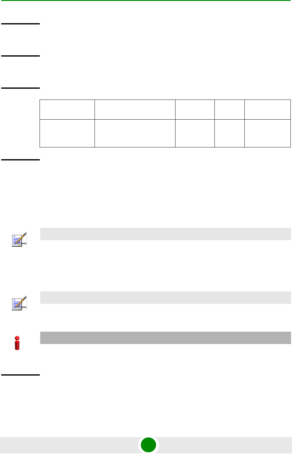
Specify the slot ID of the PSU or PIU to be enabled. The following figure depicts the
slot ID of the 4Motion shelf components:
Figure 3-1: Slot IDs of Shelf Components
For example, if you want to enable PSU, slot# 3, and disable the PIU, slot# 1, run
the following command:
npu(config)# enable PSU 3
npu(config)# disable PIU 1
Remember that a minimum AU-to-PSU/PIU ratio should always be maintained.
The following table lists the required active AU-to-PSU ratio. Before disabling the
PSU module, ensure that this ratio is maintained.
IMPORTANT
An alarm is raised if you enable a PSU or PIU that is already powered down, or you disable a PSU
or PIU that is already powered up.
IMPORTANT
An error may occur if you specify a PSU slot ID that is not in the range, 1-4, or a PIU slot ID that is
not in the range 1-2.

Chapter 3 - Operation and Administration of the Macro BTS NPU Configuration
4Motion 417 System Manual
3.4.16.1.2 Configuring the PIU Hardware Version
You need to manually configure the PIU hardware version that should be
currently in use. The system periodically checks whether the configured and
IMPORTANT
Ensure that the NPU to PSU/PIU ratio is also maintained. At least one PSU and PIU should always
be active to support the NPU.
Table 3-25: Active AU-to-PSU Ratio
If the number of Active
AUs is...
Number of active PSUs
should be...
Number of Active PIU
1-4 2 1
5-7 3 1
Command
Syntax
npu(config)# enable {PSU | PIU} <slot id>
npu(config)# disable {PSU | PIU} <slot id>
Privilege
Level
10
Syntax
Description Parameter Description Presence Default
Value
Possible
Values
{PSU | PIU} Indicates whether the PSU or
PIU slot is to be enabled or
disabled.
Mandatory N/A PSU
PIU
<slot id> Indicates the slot ID of the
PSU/PIU that you want to
enable or disable. Refer
Figure 3-1 for more
information about the slot ID
assigned to each PIU/PSU
module on the 4Motion
chassis.
Mandatory N/A 1-4 for PSU
slot
1-2 for PIU
slot
Command
Modes
Global configuration mode

Chapter 3 - Operation and Administration of the Macro BTS NPU Configuration
4Motion 418 System Manual
actual hardware versions are identical. If there is a difference in the configured
and actual versions, an alarm is raised.
The hw_version parameter indicates the current supply capability of the PIU: 58A
(high-power PIU) or 35A.
To configure the PIU hardware version, run the following command:
npu(config)# PIU <slot id (1-2)> hw_version <version (5-6)>
3.4.16.2 Configuring the GPS
The GPS is used to synchronize the air link frames of Intra-site and Inter-site
located sectors to ensure that in all sectors the air frame will start at the same
time, and that all sectors will switch from transmit (downlink) to receive (uplink)
at the same time. This synchronization is necessary to prevent Intra-site and
Inter-site sectors interference. In addition, the GPS synchronizes frame numbers
that are transmitted by the AU.
Command
Syntax
npu(config)# PIU <slot id (1-2)> hw_version <version (5-6)>
Privilege
Level
10
Syntax
Description Parameter Description Presence Default
Value
Possible
Values
<slot id (1-2)> Indicates the PIU slot ID for
which the hardware version is
to be configured.
Mandatory N/A 1-2
hw_version
<version (5-6)>
Indicates the hardware
version to be configured for
the PIU slot.
5 indicates a PIU that can
support up to 58A.
6 indicates a PIU that can
support up to 35A.
Mandatory N/A 5 (58A)
6 (35A)
Command
Modes
Global configuration mode

Chapter 3 - Operation and Administration of the Macro BTS NPU Configuration
4Motion 419 System Manual
The GPS clock generates a 1PPS signal and is connected to the 4Motion shelf via
the GPS SYNC IN connector on the front panel of the NPU. The GPS clock
requirements can be reached by an outdoor installed GPS unit when it is
synchronized to a minimum number of (user-configurable) satellites.
This section describes the commands to be used for:
“Configuring the GPS Clocks” on page 419
“Configuring General Configuration Parameters for the GPS” on page 422
“Configuring the Date and Time” on page 424
“Configuring the Daylight Saving Parameters” on page 425
“Configuring the Position” on page 426
“Configuring the Required Number of Satellites” on page 428
“Displaying GPS Clocks Parameters” on page 429
“Displaying GPS General Configuration Parameters” on page 430
“Displaying the Date and Time Parameters” on page 431
“Displaying the Daylight Saving Parameters” on page 431
“Displaying the Position Parameters” on page 432
“Displaying the Number of Satellite Parameters” on page 432
3.4.16.2.1 Configuring the GPS Clocks
The GPS clock parameters determines the source for the main clocks in the
system. To configure the GPS clock, you are required to enable/disable:
External 1PPS: Determines the air-frame start time. Assuming that all systems
use the same air-frame size and DL/UL Ratio, then, when the 1PPS clock is
received from a GPS system, this mechanism ensures inter-site and intra-site
IMPORTANT
Implementation of GPS synchronization is based on the assumption that all sectors are operating with
the same frame size and with the same DL/UL ratio.

Chapter 3 - Operation and Administration of the Macro BTS NPU Configuration
4Motion 420 System Manual
synchronization among all sectors, preventing cross interference and
saturation problems. When using the internal 1PPS clock (derived from the
selected 16 MHz clock source), only intra-site synchronization among sectors
can be achieved. You can either enable the external 1PPS clock source or use
the internal 1PPS clock source derived from the selected 16 MHz clock. By
default, the External IPPS clock is enabled. When using a GPS for
synchronization, the 1PPS clock is received from the GPS receiver and must be
enabled for proper operation.
External 16MHz: Generates all the main clocking signals in the system,
including the internal 1PPS clock. Using an external, accurate 16 MHz clock
source will enable better hold-over of the 1PPS clock upon temporary loss (or
reduced reliability when receiving less than 4 satellites) of the external 1PPS
clock. This will allow a longer time of continued operation before appearance of
interferences due to clock drifts among BSs. You can either enable the
external 16 MHz clock source or use the internal 16 MHz clock source. By
default, the external 16MHz clock is disabled. In the current release external
16MHz clock must be disabled.
To configure the GPS clock, run the following command:
npu(config)# set clock ([ External1PPS {Enable | Disable} ] [
External16MHz {Enable | Disable} ])
For example, to configure the internal 1PPS clock at the NPU to synchronize the
air frames for inter-site and intra-site sectors:
npu(config)# set clock External1PPS Disable
NOTE
If the external 1PPS GPS clock is enabled:
The concatenated slave NPU 16Mhz created from local 16MHz TCXO/OCXO at the NPU
provides holdover when the GPS loses synchronization with its satellites.
Configure the GPS parameters listed in section, Section 3.4.16.2.2.
IMPORTANT
Reset the system for changes in the GPS clock configuration to be applied to the entire system.
Command
Syntax
npu(config)# set clock ([External1PPS {Enable | Disable}] [External16MHz {Enable | Disable}])

Chapter 3 - Operation and Administration of the Macro BTS NPU Configuration
4Motion 421 System Manual
Privilege
Level
10
Syntax
Description Parameter Description Presence Default
Value
Possible
Values
External1PPS
{Enable | Disable}
Indicates whether the
external 1PPS clock is
enabled or disabled.
If the External 1PPs clock is
enabled, synchronization of
air frames for inter-site and
intra-site sectors should be
managed by the external
1PPS GPS clock. If the
External 1PPS clock is
disabled, it indicates that the
internal 1PPS at the NPU is
used to synchronize air
frames for inter-site and
intra-site sectors.
When using a GPS, External
1PPS clock must be enabled
for proper operation of the
system.
Optional Enable Enable
Disable
External16MHz
{Enable | Disable}
Indicates whether the
External 16Mhz clock is
enabled or disabled.
If the external 16 MHz is
enabled, the NPU should
receive 16Mhz signal from
the master NPU. This
parameter should be enabled
only if the NPU clock mode is
slave. If the NPU clock mode
is master, the MPU drives the
16Mhz signal towards the
slave NPUs.
In the current release
External 16MHz clock must
be disabled.
Optional Disable Enable
Disable

Chapter 3 - Operation and Administration of the Macro BTS NPU Configuration
4Motion 422 System Manual
3.4.16.2.2 Configuring General Configuration Parameters for the GPS
The GPS general configuration parameters determine how the GPS should
function with respect to the 4Motion system. Depending upon the values defined
for these parameters, you can configure the GPS clock (external 1PPS and
16MHz), and the UTC time. Run the following command to configure the global
configuration parameters for the GPS:
npu(config)# gps config ( [Type {Trimble | Lassen |
None}][HoldoverPassedTout <expiry_interval(0-2880)>]
[HoldoverPassTxOperationStop {Enable | Disable}][AlmanacUsableTime
<expiry_interval(0-4320)>] [EphemerisUsableTime
<expiry_interval(0-168)>] [IntervalToReadGPSTime{Hourly | Daily |
Monthly | Yearly}] [TimeToReadGPSTime <HH:MM:SS,DD/MM>]))
Command
Modes
Global configuration mode
IMPORTANT
Skip this section if you have selected the internal 1PPS clock. For more information about configuring
the GPS clock, refer Section 3.4.16.2.1.
IMPORTANT
An error may occur if:
Time to read GPS time is not in valid format. Correct format is hh:mm:ss, dd/mm: Minute and Second
should be within range of 0 to 60, Hour should be within the range of 0 to 23, days should be in the
range 1 to 31 and Month should be within the range of 1 to 12, also day should be valid in accordance
with month.
Command
Syntax
npu(config)# gps config ( [Type {Trimble | Lassen| None}]
[HoldoverPassedTout <expiry_interval(0-2880)>]
[HoldoverPassTxOperationStop {Enable |
Disable}][AlmanacUsableTime <expiry_interval(0-4320)>]
[EphemerisUsableTime <expiry_interval(0-168)>]
[IntervalToReadGPSTime{Hourly | Daily | Monthly | Yearly}]
[TimeToReadGPSTime <HH:MM:SS,DD/MM>]))
Privilege
Level
10

Chapter 3 - Operation and Administration of the Macro BTS NPU Configuration
4Motion 423 System Manual
Syntax
Description
Parameter Description Presence Default
Value
Possible
Values
Type {Trimble
| Lassen |
None}]
Indicates the type of GPS
connected to 4Motion:
Trimble: Use for
BMAX-Timing GPS-OGR
model.
Lassen: Use for
BMAX-4M-GPS model
None: Use when no GPS is
connected.
Optional Trimble Trimble
Lassen
None
[HoldoverTimeout
<expiry_interval
(0-2880)>]
Indicates the period, in
minutes, for which the NPU
provides holdover when the
GPS loses synchronization
with its satellites.
Optional 480 0 - 2880
[HoldoverPassTxO
perationStop{Enabl
e | Disable}]
Indicates whether the AU
modules should stop data
transmission if the GPS loses
synchronization with its
satellites and the holdover
timeout has occurred.
Optional Enable Enable
Disable
[AlmanacUsableTi
me
<expiry-interval(0-
4320)>]
Indicates the maximum
period, in hours, for which the
Almanac time is valid when
the GPS is reset.
Optional 720 0-4320
[EphemerisUsable
Time
<expiry-interval(0-
168)>]
Indicates the maximum
period, in hours, for which the
Ephemeris time is valid when
the GPS is reset.
Optional 4 0-168
[IntervalToReadGP
STime {Hourly |
Daily | Monthly |
Yearly}]
Indicates the interval after
which the NPU should obtain
the GPS time for frame
synchronization, and send it
to the AU.
Optional Daily Hourly
Daily
Monthly
Yearly

Chapter 3 - Operation and Administration of the Macro BTS NPU Configuration
4Motion 424 System Manual
3.4.16.2.3 Configuring the Date and Time
The UTC time is used to configure the following:
Local time: Differs from the UTC time with respect to the value you have
specified for the localUTCDiff and DST parameters. The local time is equal to
the sum of the UTC time, the value of the localUTCDiff parameter (local
offset from UTC time) and DST (daylight saving time offset). For more
information about configuring this parameter, “Configuring the GPS Clocks”
on page 419. You can use the CLI to display the current local time. For details,
refer the section, “Displaying the Date and Time Parameters” on page 431.
System time: Refers to the operating system (kernel) time that is identical to
the UTC time when the system boots up. The system time is updated every
hour with the time received from the GPS receiver.
Real Time Clock (RTC) time: Refers to the time maintained by the board’s
hardware clock. By default, the RTC time is set to 1st January, 1970. The RTC
time is updated every hour with the UTC time that is received from the GPS
receiver or that you have configured from the CLI. The RTC time is used for
creating the timestamp for log and trace messages, performance data
collection files, and for managing the interval after which a backup of the
configuration file should be maintained and performance data should be
collected.
Execute the following command to configure the date and time parameters. If the
GPS is synchronized to its satellites and is connected to 4Motion, the UTC time is
provided by the GPS. Otherwise the UTC time that you configure is used instead.
To configure the date and time parameters, run the following command:
npu(config)# set date [UTC <HH:MM:SS,DD/MM/YYYY>] [LocalUTCDiff
<+/-HH:MM>] [DST <(0-2)>]
[TimeToReadGPS
Time
<HH:MM:SS,DD/M
M>]
Indicates the time when the
NPU should obtain the GPS
time for frame
synchronization..
Optional 04:05 HH:MM:SS,DD
/MM
Command
Modes
Global configuration mode

Chapter 3 - Operation and Administration of the Macro BTS NPU Configuration
4Motion 425 System Manual
3.4.16.2.4 Configuring the Daylight Saving Parameters
To configure the daylight saving parameters, run the following command:
npu(config)# set daylight saving ([mode {Enable | Disable}]
[start-date <DD.MM>] [stop-date <DD.MM>])
IMPORTANT
An error may occur if :
1) UTC time is not in the valid format i.e. hh: mm: ss, dd/mm/yyyy.
2) Local UTCDiff is not valid format i.e. +/-hh:mm
3) Local UTC Diff is out of the range between -12 to +13 or it is not in steps of 30 minutes.
4) DST is out of range i.e between 0 to 2
Command
Syntax
npu(config)# set date [UTC <HH:MM:SS,DD/MM/YYYY>] [LocalUTCDiff <+/-HH:MM>] [DST
<(0-2)>]
Privilege
Level
10
Syntax
Description Parameter Description Presence Default
Value
Possible
Values
UTC
<HH:MM:SS,DD/M
M/YYYY>
Indicates the UTC time to be
used for 4Motion if not
available from GPS.
Optional N/A Use the format:
HH:MM: SS,
DD/MM/YYYY
LocalUTCDiff
<+/-HH:MM>
The local offset from UTC Optional +00:00 +/-HH:MM
HH: -12 to +13
MM: 00 or 30
DST <(0-2)> Applicable only of
daylightSavingMode is set to
Enable. Daylight Saving Time
offset of the local clock
Optional 0 0-2
Command
Modes
Global configuration mode
IMPORTANT
An error may occur if any of the configured value is not in a valid format:

Chapter 3 - Operation and Administration of the Macro BTS NPU Configuration
4Motion 426 System Manual
3.4.16.2.5 Configuring the Position
The position configuration enables setting the location’s parameters when GPS is
not used (Type=None).
To configure the position parameters, run the following command:
Command
Syntax
npu(config)# set daylight saving ([mode {Enable | Disable}] [start-date <DD.MM>] [stop-date
<DD.MM>])
Privilege
Level
10
Syntax
Description Parameter Description Presence Default
Value
Possible
Values
mode {Enable |
Disable}
Enables/disables the daylight
saving feature. When
enabled, the feature will be
activated using the
parameters defined below.
Optional Disable Enable
Disable
start-date
<DD.MM>
Applicable only of Mode is set
to Enable. The date for
starting the daylight saving
feature: At the beginning of
this date (midnight), the clock
will be advanced by the
amount of hours specified by
the Advance Factor
parameter.
Optional 27.3 DD.MM
DD: .day in
month, 1-31.
MM .month in
year, 1-12.
stop-date
<DD.MM>
Applicable only of Mode is set
to Enable. The date for
stopping the daylight saving
feature: At the end of this
date (midnight plus the
amount of hours specified by
the Advance Factor
parameter), the clock will be
set back to midnight (00:00).
Optional 28.11 DD.MM
DD: .day in
month, 1-31.
MM .month in
year, 1-12.
Command
Modes
Global configuration mode

Chapter 3 - Operation and Administration of the Macro BTS NPU Configuration
4Motion 427 System Manual
npu(config)# set position ([Latitude <xx.xxx,N/S>] [Longitude
<xxx.xxx,E/W>] [Altitude (-300 - 9000)])
IMPORTANT
An error may occur if :
1) Latitude, longitude and altitude are configured while GPS type is not "None".
2) Latitude is not in valid format i.e. ll.mmm,a where a is either N or S
3) Longitude is not in valid format i.e. lll.mmm,a where a is either E or W.
4) Altitude is not in valid range i.e. +-300 to 9000.
Command
Syntax
npu(config)# set position ([Latitude <xx.xxx,N/S>] [Longitude <xxx.xxx,E/W>] [Altitude (-300 -
9000)])
Privilege
Level
10
Syntax
Description Parameter Description Presence Default
Value
Possible
Values
Latitude
<xx.xxx,N/S>
Indicates the latitude where
the 4Motion shelf is currently
positioned. Configure only if
GPS Type is None.
Optional 00.000,N Use the format,
ll.mmm.a
(where ll.mmm
is in degrees
and the value
of a is either N
or S).
ll is between 00
to 89, mmm is
between 000 to
999.

Chapter 3 - Operation and Administration of the Macro BTS NPU Configuration
4Motion 428 System Manual
3.4.16.2.6 Configuring the Required Number of Satellites
The satellite parameter enables configured the minimum number of satellites
required for maintaining synchronization and for renewing synchronization after
synchronization loss.
To configure the satellite parameters, run the following command:
npu(config)# set satellite ([MinNumOfSatForHoldoverReturn <range
(1-12)>] [MaxNumOfSatBeforeSyncLoss <range (0-11)>])
Longitude
<xxx.xxx,E/W>
Indicates the longitude where
the 4Motion shelf is currently
positioned. Configure only if
GPS Type is None.
Optional 000.000,E Use the format,
Ill.mmm.a
(where ll.mmm
is in degrees
and the value
of a is either E
or W).
lll is between
000 to 179,
mmm is
between 000 to
999.
Altitude (-300 -
9000)])
Indicates the altitude (in
meters) where the 4Motion
shelf is currently positioned.
Configure only if GPS Type is
None.
Optional 0 -300 to 9000
Command
Modes
Global configuration mode
IMPORTANT
1) An error can occur while configuring MinNumOfSatForHoldoverReturn if Minimum number of
satellite for holdover return is less than Maximum number of satellite before synchronization loss.
2) An error can occur while configuring MaxNumOfSatBeforeSyncLoss if Maximum number of satellite
before synchronization is more than Minimum number of satellite for holdover return.
Command
Syntax
npu(config)# set satellite ([MinNumOfSatForHoldoverReturn <range (1-12)>]
[MaxNumOfSatBeforeSyncLoss <range (0-11)>]
Privilege
Level
10

Chapter 3 - Operation and Administration of the Macro BTS NPU Configuration
4Motion 429 System Manual
3.4.16.2.7 Displaying GPS Clocks Parameters
To display the GPS clock configuration parameters, run the following command:
npu# show clock status [{CurrentExternal1PPS |
ConfiguredExternal1PPS | CurrentExtrnal16MHz |
ConfiguredExternal16MHz}]
Syntax
Description Parameter Description Presence Default
Value
Possible
Values
MinNumOfSatForH
oldoverReturn
<range (1-12)>
Indicates the minimum
number of satellites that
should be received for
resuming synchronization
(exiting holdover status) after
loss of synchronization.
Optional 2 1-12
MaxNumOfSatBef
oreSyncLoss
<range (0-11)>
Indicates the minimum
number of satellites required
for maintaining
synchronization.
Optional 1 0-11
Command
Modes
Global configuration mode
Command
Syntax
npu# show clock status [{CurrentExternal1PPS |
ConfiguredExternal1PPS | CurrentExtrnal16MHz |
ConfiguredExternal16MHz}
Privilege
Level
1
Syntax
Description
For a detailed description of each parameter in this command, refer the section, “Configuring
the GPS Clocks” on page 419.
Both Current and Configured values for each clock are provided (the parameters are applied after
reset)

Chapter 3 - Operation and Administration of the Macro BTS NPU Configuration
4Motion 430 System Manual
3.4.16.2.8 Displaying GPS General Configuration Parameters
To display the GPS general configuration parameters, run the following command:
npu# show gps config [{ Type | SoftwareVersion [{ Navigation |
Signal }] | HoldoverPassedTout | HoldoverPassTxOperationStop |
AlmanacUsableTime | EphemerisUsableTime | IntervalToReadGPSTime |
TimeToReadGPSTime} ]
Display
Format
Configured External 1PPS Status :Enable/ Disable
Current External 1PPS Status :Enable/ Disable
Configured External 16MHz Status :Enable/ Disable
Current External 16MHz Status :Enable/ Disable
Command
Modes
Global command mode
Command
Syntax
npu# show gps config [{ Type | SoftwareVersion [{ Navigation | Signal }] |
HoldoverPassedTout | HoldoverPassTxOperationStop | AlmanacUsableTime |
EphemerisUsableTime | IntervalToReadGPSTime | TimeToReadGPSTime} ]
Privilege
Level
1
Syntax
Description
For a detailed description of each parameter in this command, refer the section, “Configuring
General Configuration Parameters for the GPS” on page 422.
Display
Format
Configured GPS Type :
GPS Navigation Processor SW Version :
GPS Signal Processor SW version :
Holdover Timeout :
HoldoverPassedTxOperationStop :
Almanac Usable Time :
Ephemeris Usable Time :
Interval To Read Gps Time :
Time To Read Gps Time :

Chapter 3 - Operation and Administration of the Macro BTS NPU Configuration
4Motion 431 System Manual
In addition to the configuration parameters, the SW Versions of the GPS
Navigation and Signal Processors are also displayed (if available).
3.4.16.2.9 Displaying the Date and Time Parameters
To display the current date parameters, run the following command:
npu# show date [{Local | UTC | LocalUTCDiff | DST}]
In addition to the configurable parameters, the calculated Local Time is also
displayed.
3.4.16.2.10 Displaying the Daylight Saving Parameters
To display the current daylight saving parameters, run the following command:
npu# show daylight saving
Command
Modes
Global command mode
Command
Syntax
npu# show date [{Local | UTC | LocalUTCDiff | DST}]
Privilege
Level
1
Syntax
Description
For a detailed description of each parameter in this command, refer the section, “Configuring
the Date and Time” on page 424.
Display
Format
Local Time :
UTC Time :
Local UTC Offset :
Daylight Saving Time :
Command
Modes
Global command mode
Command
Syntax
npu# show daylight saving

Chapter 3 - Operation and Administration of the Macro BTS NPU Configuration
4Motion 432 System Manual
3.4.16.2.11 Displaying the Position Parameters
To display the current position parameters, run the following command:
npu# show position [{Latitude | Longitude | Altitude}]
3.4.16.2.12 Displaying the Number of Satellite Parameters
To display the current satellite parameters, run the following command:
Privilege
Level
1
Display
Format
Saving mode :<enabled/disabled>
Start date :<value or not configured>
Stop date :<value or not configured>
Command
Modes
Global command mode
Command
Syntax
npu# show position [{Latitude | Longitude | Altitude}]
Privilege
Level
1
Syntax
Description
For a detailed description of each parameter in this command, refer the section, “Configuring
the Position” on page 426.
Display
Format
Latitude :
Longitude :
Altitude :
Command
Modes
Global command mode

Chapter 3 - Operation and Administration of the Macro BTS NPU Configuration
4Motion 433 System Manual
npu# show satellite [{MinNumOfSatForHoldoverReturn |
MaxNumOfSatBeforeSyncLoss | NumOfSatelliteAvailable}]
In addition to the configurable parameters, the current number of satellites
acquired by the GPS receiver is also displayed.
3.4.16.3 Managing Power Feeders Configuration
The Power Feeder configuration enables specifying the AU port connected to each
Power Feeder port.
3.4.16.3.1 Configuring Power Feeders
To configure the AU ports connected to the ports of a specific Power Feeder, run
the following command:
npu(config)# config pfUnitNo <pfunit no (1-4)> pfPortNo <pfport no
(1-4)> AuSlotNo <AuslotNo (-1,1-4,7-9)> AuPortNo <AuPortNo
(-1,1-4)>
Command
Syntax
npu# show satellite [{MinNumOfSatForHoldoverReturn | MaxNumOfSatBeforeSyncLoss |
NumOfSatelliteAvailable}]
Privilege
Level
1
Syntax
Description
For a detailed description of each parameter in this command, refer the section, “Configuring
the Required Number of Satellites” on page 428.
Display
Format
Max Satellites Before Sync Loss :
Min Satellites For Holdover Return :
Number of Satellites Acquired :
Command
Modes
Global command mode
IMPORTANT
An error can occur if the configured combination of AuPortNo and AuSlotNo already exists.
Command
Syntax
npu(config)# config pfUnitNo <pfunit no (1-4)> pfPortNo <pfport no (1-4)> AuSlotNo <AuslotNo
(-1,1-4,7-9)> AuPort <AuPortNo (-1,1-4)>

Chapter 3 - Operation and Administration of the Macro BTS NPU Configuration
4Motion 434 System Manual
3.4.16.3.2 Displaying Configuration Information for Power Feeders
To display configuration information for all defined Power Feeders, run the
following command:
Privilege
Level
10
Syntax
Description Parameter Description Presence Default
Value
Possible
Values
pfUnitNo <pfunit no
(1-4)>
The Power Feeder unit
number.
Mandatory N/A 1-4
pfPortNo <pfport
no (1-4)>
Each combination
of Power Feeder
Unit Number and
Port Number can
appear in a
maximum of one
Power Feeder
instance
The Power Feeder port
number
Mandatory N/A 1-4
AuSlotNo
<AuslotNo
(-1,1-4,7-9)>
The AU Slot number.
-1 means none.
Optional -1 (none) -1 (none), 1-4,
7-9
AuPortNo
<AuPortNo
(-1,1-4)>
Each combination
of AU Slot Number
and Port Number
can appear in a
maximum of one
Power Feeder
instance (excluding
combinations with
a none value).
The AU Port number.
-1 means none.
Optional -1 (none) -1 (none), 1-4
Command
Modes
Global configuration mode

Chapter 3 - Operation and Administration of the Macro BTS NPU Configuration
4Motion 435 System Manual
npu# show power-feeder configuration
3.4.16.4 Managing Dry-contact Input Alarms
Dry-contact input alarms are external devices that are connected to the 4Motion
unit, and notify the system when there is a change in external conditions. When
the system receives this notification, an SNMP trap is sent to the EMS. For
example, a device such as a temperature sensor that is connected to the 4Motion
unit, and configured to function as a dry-contact input alarm, can raise an alarm
to the system when there is a sudden change in the room temperature. The
system then sends an SNMP trap to the EMS, notifying the administrator of the
change indicated by the external device.
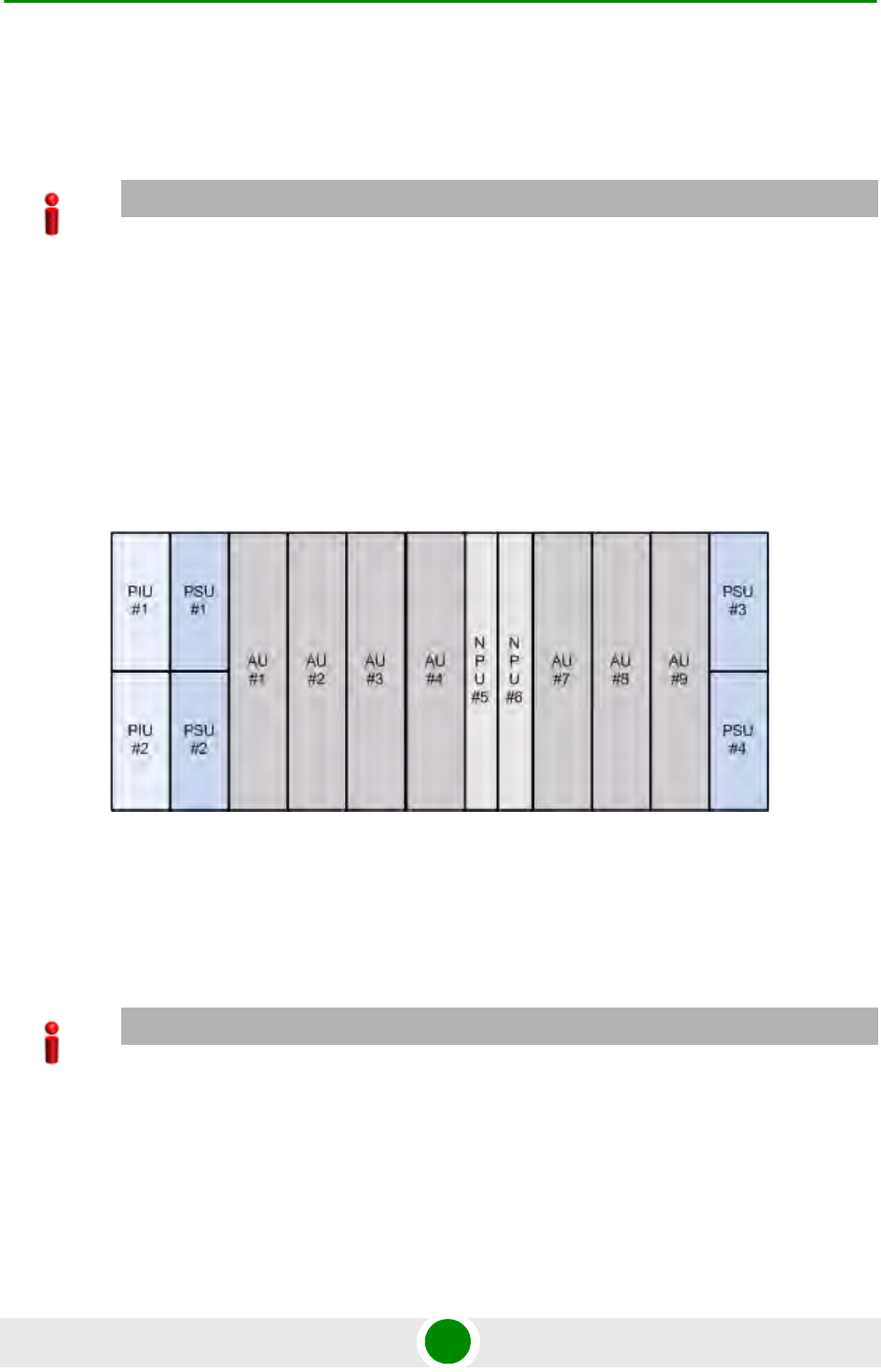
Dry contact input alarms are connected to the 4Motion system via a 25-pin micro
D-Type ALRM-IN/OUT connector on the NPU front panel. The following figure
depicts the ALRM-IN/OUT connector, and the pin numbers assigned to each pin:
Command
Syntax
npu# show power-feeder configuration
Privilege
Level
1
Display
Format (for
each
configured
instance)
PfUnitNo : <value>, PfPortNo : <value>, AuPortNo : <value>, AuSlotNo : <value>
........
Command
Modes
Global command mode
Chapter 3 - Operation and Administration of the Macro BTS NPU Configuration
4Motion 436 System Manual
Figure 3-2: 25-pin Micro D-Type ALRM-IN/OUT Connector
You can configure upto eight dry contact input alarms, each mapping to a
different pin number. This section describes the commands to be executed for:
“Mapping a Dry-contact Input Alarm to an Alarm Condition” on page 436
“Disabling Dry-contact Input Alarms” on page 439
3.4.16.4.1 Mapping a Dry-contact Input Alarm to an Alarm Condition
Dry contact alarms are connected to the 4Motion unit via the 25-pin micro D-Type
ALRM-IN/OUT connector on the front panel of the NPU. You can configure upto
eight dry contact input alarms, each connected to a different pin on the
ALRM-IN/OUT connector. Each alarm can then map to any of the following alarm
conditions. If the external dry-contact alarm detects that any of these conditions
is fulfilled, an alarm is raised, and a corresponding trap is sent to the EMS.
Commercial power failure
Fire
Enclosure door open
High temperature
IMPORTANT
Dry-contact input alarms are a means to raise a trap to the EMS when a change in conditions is
notified by the external device. However, the trap may not reach the EMS because of trap rate limiting,
network congestion or for reasons relating to the external equipment. Alvarion does not assume
responsibility for traps that are lost.

Chapter 3 - Operation and Administration of the Macro BTS NPU Configuration
4Motion 437 System Manual
Flood
Low fuel
Low battery threshold
Generator failure
Intrusion detection
External equipment failure
To map the a dry contact alarm to an alarm condition, run the following
command:
npu(config)# dry-contact IN <alarm_num (1-8)> alarm
{CommercialPowerFailure | Fire | EnclosueDoorOpen | HighTemperature
| Flood | LowFuel | LowBatteryThreshold | GeneratorFailure |
IntrusionDetection | ExternalEquipmentFailure} [alarmPolarity
{RaiseOnClose | RaiseOnOpen }]
In this command, the alarm_num parameter maps to a pin on the ALRM IN-OUT
connector.
The following table lists the pin numbers of the 25-pin micro D-Type
ALRM-IN/OUT connector corresponding to the alarm number you are configuring:
Refer Figure 3-2 for a diagrammatic representation of the 25-pin micro D-Type
ALRM-IN/OUT connector and the numbers assigned to each pin.
Table 3-26: Pin Numbers Corresponding to Dry Contact Input Alarm Numbers
Pin Number Alarm Number
3 and 15 1
4 and 16 2
5 and 17 3
6 and 18 4
7 and 19 5
8 and 20 6
9 and 21 7
10 and 22 8

Chapter 3 - Operation and Administration of the Macro BTS NPU Configuration
4Motion 438 System Manual
NOTE
For more information about displaying the alarm conditions currently mapped to the micro D-Type
ALRM-IN/OUT connector pins, refer Section 3.4.16.6.
Command
Syntax
npu(config)# dry-contact IN <alarm_num (1-8)> alarm {CommercialPowerFailure | Fire |
EnclosueDoorOpen | HighTemperature | Flood | LowFuel | LowBatteryThreshold | GeneratorFailure
| IntrusionDetection | ExternalEquipmentFailure} [alarmPolarity {RaiseOnClose | RaiseOnOpen }]
Privilege
Level
10
Syntax
Description Parameter Description Presence Default
Value
Possible Values
<alarm_num
(1-8)>
Indicates the alarm
number of the dry
contact input alarm
that is to be mapped
to an alarm condition.
This alarm number
corresponds to a pin
on the 25-pin micro
D-Type jack.
For more information
about the pin numbers
that correspond to the
alarm number, refer
Table 3-26.
Mandatory N/A 1-8

Chapter 3 - Operation and Administration of the Macro BTS NPU Configuration
4Motion 439 System Manual
3.4.16.4.2 Disabling Dry-contact Input Alarms
To disable (block) a dry contact input alarm mapped to a specific alarm condition,
run the following command:
npu(config)# no dry-contact IN <alarm_num (1-8)>
alarm
{CommercialPower
Failure | Fire |
EnclosueDoorOpe
n |
HighTemperature |
Flood | LowFuel |
LowBatteryThresh
old |
GeneratorFailure |
IntrusionDetection
|
ExternalEquipment
Failure
Indicates the alarm
condition to be
mapped to a pin
number.
Mandatory N/A CommercialPowerFai
lure
Fire
EnclosueDoorOpen
HighTemperature
Flood
LowFuel
LowBatteryThreshold
GeneratorFailure
IntrusionDetection
External
ExternalEquipmentFa
ilure (can be used
for defining a
condition other than
the ones specified
by the other
parameters in this
command)
[alarmPolarity
{RaiseOnClose |
RaiseOnOpen }]
Indicates whether
alarm will be raised on
closed or open circuit
condition.
Optional RaiseOn
Close
RaiseOnClose
RaiseOnOpen
Command
Modes
Global configuration mode
NOTE
For more information about mapping dry contact alarms to an alarm condition, refer to “Mapping
a Dry-contact Input Alarm to an Alarm Condition” on page 436. For more information
about displaying the alarm condition currently mapped to an alarm, refer to “Displaying
Configuration Information for Dry-contact Input/Output Alarms” on page 443.

Chapter 3 - Operation and Administration of the Macro BTS NPU Configuration
4Motion 440 System Manual
3.4.16.5 Managing Dry-contact Output Alarms
Dry-contact output alarms are raised by the system to notify an external device
connected to the 4Motion unit about a change in the system state. The external
monitoring entity may take the appropriate action after receiving the notification
from the 4Motion system.
You can use the CLI to raise an alarm to the external entity that is connected to
the dry contact output pin. After the system returns to its normal state, you can
clear the dry contact output alarm that you had raised.
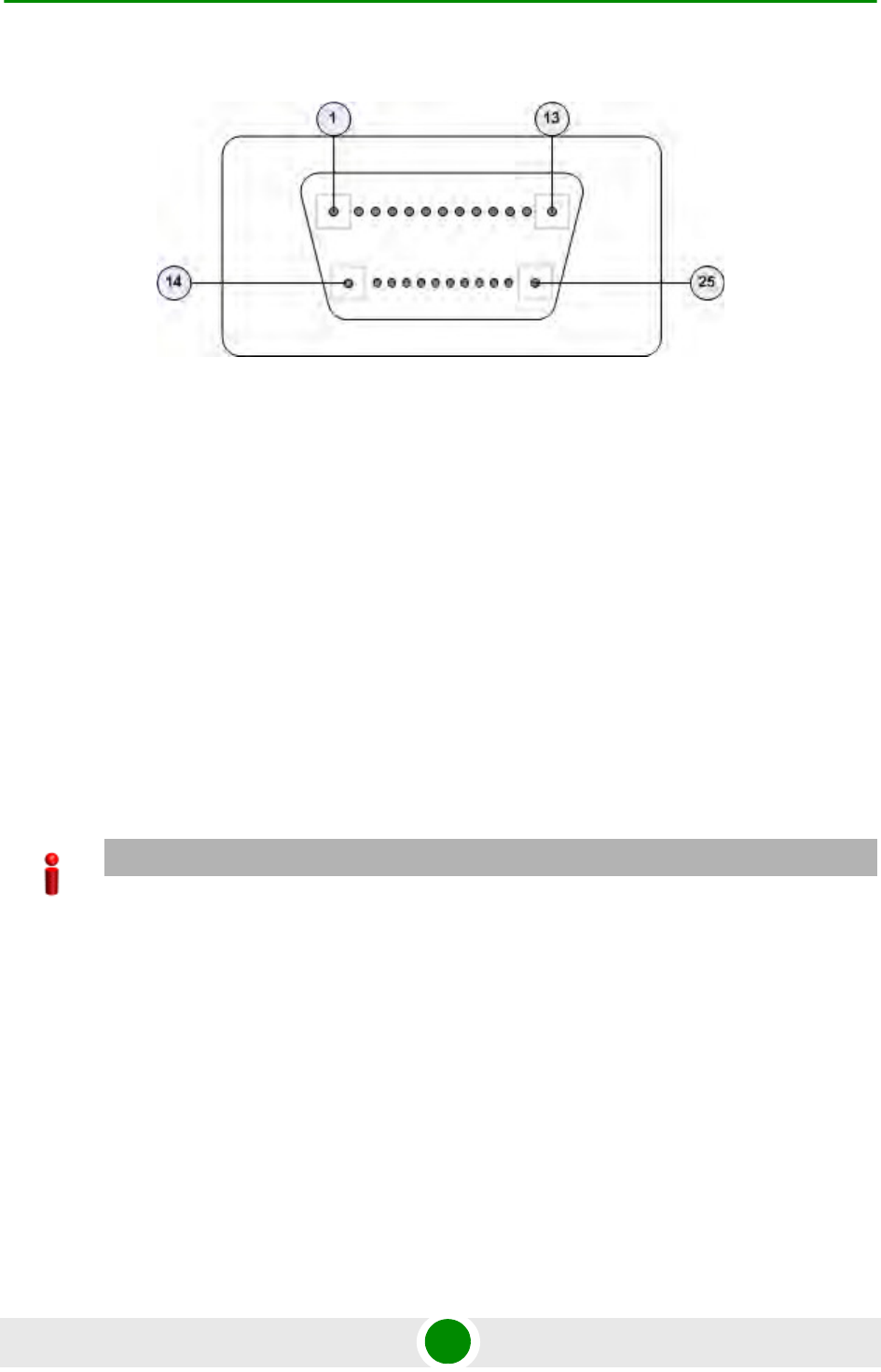
Dry contact output alarms are connected to the 4Motion system via a 25-pin
micro D-Type ALRM-IN/OUT connector on the NPU front panel. The following
figure depicts the ALRM-IN/OUT connector, and the pin numbers assigned to
each pin:
Command
Syntax
npu(config)# no dry-contact IN <alarm_num (1-8)>
Privilege
Level
10
Syntax
Description Parameter Description Presence Default
Value
Possible
Values
<alarm_num
(1-8)>
Indicates the alarm number of
the dry contact input alarm
alarm that is to be disabled.
The value of this parameter
should be between 1 and 8.
For more information about
the pin numbers that
correspond to the alarm
number, refer Table 3-26.
Mandatory N/A 1-8
Command
Modes
Global configuration mode
Chapter 3 - Operation and Administration of the Macro BTS NPU Configuration
4Motion 441 System Manual
Figure 3-3: 25-pin Micro D-Type ALRM-IN/OUT Connector
You can configure upto three dry contact output alarms, each mapping to a
different pin number. This section describes the commands used for:
“Raising Dry-contact Output Alarms” on page 441
“Clearing Dry-contact Output Alarms” on page 442
3.4.16.5.1 Raising Dry-contact Output Alarms
You can raise a dry contact output alarm to any external entity that is connected
to the 4Motion unit via the 25-pin micro D-Type jack on the NPU front panel. To
raise a dry contact output alarm, run the following command:
npu(config)# dry-contact OUT <alarm_num (1-3)> alarm <alarm name >
In this command, the alarm_num parameter maps to a specific pin of the micro
D-Type ALRM-IN/OUT connector. The following table lists the pin numbers of the
25-pin micro D-Type ALRM-IN/OUT connector corresponding to the alarm
number you are configuring:
In this table, N.C denotes Normally Closed, and N.O denotes Normally Open.
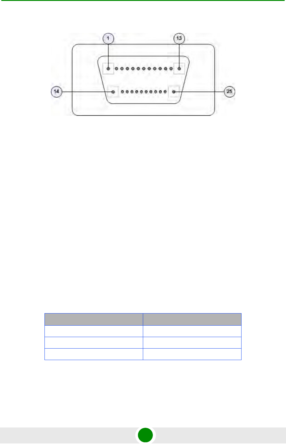
Refer Figure 3-3 for a diagrammatic representation of the 25-pin micro D-Type
ALRM-IN/OUT connector and the numbers assigned to each pin.
Table 3-27: Pin Numbers Corresponding to Dry Contact Output Alarm Numbers
Pin Number Corresponding Alarm Number
1(FIX) - 2(N.C) - 14(N.O) 1
11(FIX)- 12(N.C) - 13(N.O) 2
23(FIX) - 24(N.C) - 25(N.O) 3

Chapter 3 - Operation and Administration of the Macro BTS NPU Configuration
4Motion 442 System Manual
3.4.16.5.2 Clearing Dry-contact Output Alarms
After the system returns to its normal state, run the following command to clear
the dry-contact output alarm that you had raised:
npu(config)# no dry-contact OUT <alarm_num (1-3)>
After you run this command, the alarm that you had raised is cleared.
NOTE
After you have raised an alarm, clear this alarm when the system state returns to its normal
condition. For information, refer to, “Clearing Dry-contact Output Alarms” on page 442.
For more information about displaying configuration information about a dry contact output alarm,
refer to “Displaying Configuration Information for Dry-contact Input/Output
Alarms” on page 443.
Command
Syntax
npu(config)# dry-contact OUT <alarm_num (1-3)> alarm <alarm name >
Privilege
Level
10
Syntax
Description Parameter Description Presence Default
Value
Possible
Values
<alarm_num
(1-3)>
Indicates the alarm number of
the dry contact output alarm
that is to be configured. This
alarm number corresponds to
a pin on the 25-pin micro
D-Type jack.
For more information about
pin numbers that correspond
to the alarm number, refer
Table 3-27.
Mandatory N/A 1-3
alarm <alarm
name>
Indicates the name of the
dry-contact alarm to be
raised.
Mandatory N/A Up to 256
characters
Command
Modes
Global configuration mode
Chapter 3 - Operation and Administration of the Macro BTS NPU Configuration
4Motion 443 System Manual
3.4.16.6 Displaying Configuration Information for Dry-contact
Input/Output Alarms
To display configuration information for dry-contact input/output alarms, run the
following command:
npu# show dry-contact {IN | OUT} [<alarm_num>]
If you want to display configuration information for input or output alarms,
specify IN or OUT. You can also specify the pin number if you want to view
configuration information for particular pin used for connecting an external device
to the 4Motion unit.
For example, run the following command if you want to display configuration
information for the dry contact input alarm connected to the 4Motion unit via
pin# 8 on the NPU panel:
npu# show dry-contact IN 8
NOTENOTE
For more information about raising a dry contact output alarm, refer to “Raising Dry-contact
Output Alarms” on page 441.
Command
Syntax
npu(config)# no dry-contact OUT <alarm_num (1-3)>
Privilege
Level
10
Syntax
Description Parameter Description Presence Default
Value
Possible
Values
<alarm_num
(1-3)>
Indicates the alarm number of
the dry contact output alarm
alarm that is to be disabled.
For more information about
the pin numbers that
correspond to the alarm
number, refer Table 3-27.
Mandatory N/A 1-3
Command
Modes
Global configuration mode

Chapter 3 - Operation and Administration of the Macro BTS NPU Configuration
4Motion 444 System Manual
If you want to display configuration information for all dry contact IN alarms, run
the following command:
npu# show dry-contact IN
NOTE
An error may occur if you have specified an incorrect pin number for a particular input/output alarm.
For more information about the correct pin-to-alarm number mapping, refer Table 3-26 and
Table 3-27.
Command
Syntax
npu# show dry-contact {IN | OUT} [<alarm_num>]
Privilege
Level
1
Syntax
Description Parameter Description Presence Default
Value
Possible
Values
{IN|OUT} Indicates whether
configuration information is to
be displayed for input or
output alarms.
Optional N/A IN
OUT
[<alarm_num>] Denotes the alarm number of
the input or output alarm for
which configuration
information is to be displayed.
If you do not specify this
value, configuration
information is displayed for all
input or output alarms.
Refer Figure 3-2 and
Figure 3-3 for more
information about the
numbers assigned to the pins
used for connecting dry
contact alarms.
Optional N/A 1-8 for input
alarms
1-3 for
output
alarms

Chapter 3 - Operation and Administration of the Macro BTS NPU Configuration
4Motion 445 System Manual
3.4.16.7 Managing the Site General Information for the 4Motion Shelf
The site general parameters provide general information on the site.
This section describes the commands used for:
“Configuring the Site General Information for the 4Motion Shelf” on page 445
“Displaying the Site General Information Parameters” on page 446
3.4.16.7.1 Configuring the Site General Information for the 4Motion Shelf
Run the following command to configure the 4Motion shelf location information,
such as the rack number and location:
npu(config)# site {Name <name (32)> | Address <address(70)> |
RackLocation <rack no. + position in rack (32)> | ContactPerson
<name (32)>}
For example, run the following command if you want to specify the site name:
npu(config)# site name Site 12
Display
Format
Dry-Contact Input Alarm:
AlarmNumber AlarmName InputBlocking AlarmPolarity
<alarm num> <alarm name> <Yes or No> Raise On Close/Open
Dry-Contact Output Alarm:
AlarmNumber AlarmStatus AlarmName
<alarm num> <On or Off> <name>
Command
Modes
Global command mode
IMPORTANT
An error may occur if the length of any of these parameters exceeds the specified range. Refer the
syntax description for more information about the appropriate values and format for configuring
these parameters.

Chapter 3 - Operation and Administration of the Macro BTS NPU Configuration
4Motion 446 System Manual
3.4.16.7.2 Displaying the Site General Information Parameters
To display configuration information for the site general information parameters,
run the following command:
npu# show site [{Name | Address | RackLocation | ContactPerson
|ProductType}]
In addition to the configurable parameter (see Section 3.4.16.7.1), you can also
display the Product Type.
If you want to display configuration information for one parameter, specify only
the required parameter. If you want to display configuration information for all dry
contact alarms, run the following command:
npu# show site
Command
Syntax
npu(config)# site (Name <name (32)> | Address <address(70)> | RackLocation <rack no. + position
in rack (32)> | ContactPerson <name (32)>)
Privilege
Level
10
Syntax
Description Parameter Description Presence Default
Value
Possible
Values
Name <name
(256)>}
Indicates the name of the
4Motion shelf.
Optional N/A String (up to 32
characters)
Address <address
(256)>}
Indicates the address of the
4Motion site.
Optional N/A String (up to 70
characters)
RackLocation
<rack no. +
position in rack
(256)>}
Indicates the rack number
and location of the 4Motion
shelf.
Optional N/A String (up to 32
characters)
ContactPerson
<name (256)>
Indicates the name of person
who is administering the
4Motion shelf.
Optional String (up to 32
characters)
Command
Modes
Global configuration mode

Chapter 3 - Operation and Administration of the Macro BTS NPU Configuration
4Motion 447 System Manual
3.4.16.8 Managing the Unique Identifier for the 4Motion Shelf
The Site Identifier (Site ID) is used by the management system as identifier of the
site and must be unique in the managed network.
The default value 0 is not a valid Site Identifier: it indicates that the Site Identifier
was not configured and a valid Site Identifier must be configured. A BTS with Site
Identifier 0 will not be discovered by AlvariSTAR.
Since the Site Identifier is used by AlvariSTAR to identify the device, it is highly
recommended not to modify it. If necessary, you must follow the Site Number
Change process described in the AlvariSTAR Device Manager User Manual.
This section describes the commands used for:
“Configuring the Unique Identifier for the 4Motion Shelf” on page 447
“Displaying the Unique Identifier for the 4Motion Shelf” on page 448
3.4.16.8.1 Configuring the Unique Identifier for the 4Motion Shelf
To configure a unique identifier for the 4Motion shelf, run the following command:
npu(config)# site identifier <site id <1-999999>>
Command
Syntax
npu# show site [{Name | Address | RackLocation | ContactPerson |ProductType }]
Privilege
Level
1
Display
Format
(for all
parameters)
Name :
Address :
Rack Location :
Contact Person :
Product Type :
Command
Modes
Global command mode

Chapter 3 - Operation and Administration of the Macro BTS NPU Configuration
4Motion 448 System Manual
3.4.16.8.2 Displaying the Unique Identifier for the 4Motion Shelf
To display the unique identifier for the 4Motion shelf, run the following command:
npu# show site identifier
IMPORTANT
You must save the configuration (run the command npu# write) for a change in site identifier to take
effect after next reset.
Since the site identifier (Site Number) is used by AlvariSTAR management system to identify the
device, it is highly recommended not to modify it. If necessary, you must follow the Site Number
Change process described in the Device Driver Manual.
NOTE
To display the 4Motion shelf identifier, refer to “Displaying the Unique Identifier for the
4Motion Shelf” on page 448.
Command
Syntax
npu(config)# site identifier <site id <1-999999>>
Privilege
Level
10
Syntax
Description Parameter Description Presence Default
Value
Possible
Values
<site id
<1-999999>>
Indicates the ID of the
4Motion shelf.
Mandatory N/A 1-999999
Command
Modes
Global configuration mode
Command
Syntax
npu# show site identifier
Privilege
Level
1

Chapter 3 - Operation and Administration of the Macro BTS NPU Configuration
4Motion 449 System Manual
3.4.16.9 Displaying the Vendor Identifier
The Vendor Identifier, used as a unique identifier of the equipment vendor, can be
configured only by the vendor. To display the vendor identifier, run the following
command:
npu# show vendor identifier
Display
Format
Site Id :
Command
Modes
Global command mode
Command
Syntax
npu# show vendor identifier
Privilege
Level
1
Display
Format
Vendor Id :
Command
Modes
Global command mode

Chapter 3 - Operation and Administration of the Macro BTS Managing MS in ASN-GW
4Motion 450 System Manual
3.5 Ma na ging MS in ASN-GW
This section describes the MS level commands.
“Manual MS De-registration”
“Displaying MS Information”
3.5 .1 Manual MS De -re gist ration
Run the following command to initiate the de-registration process of the MS with a
specified NAI or MSID (MAC address) value, all MSs served by a specific BS or all
the MSs served by the unit.
npu(config)# de-reg ms {nai <nai-string> | bs <(1 to 16777215 StepSize 1)> | msid
<msid-string> | all}
IMPORTANT
An error may occur if NAI or MSID value is not specified. Refer to the syntax description for more
information about the appropriate values and format for configuring this parameter.
An error may occur also for “MS not found", in case no MS with the specified NAI or MSID is
registered at ASNGW.
Command
Syntax
npu(config)# de-reg ms {nai <nai-string> | bs <(1 to 16777215 StepSize 1)> | msid <msid-string> |
all}
Privilege
Level
10

Chapter 3 - Operation and Administration of the Macro BTS Managing MS in ASN-GW
4Motion 451 System Manual
3.5 .2 Displa ying MS Information
Run the following command to view the MS context information of all MSs or a
single MS:
npu# show ms info [detailed [{nai|msid}<string>]] [hotlined]
Syntax
Description Parameter Description Presence Default
Value
Possible
Values
{nai <nai-string>
|bs <(1 to
16777215
StepSize 1)> |
msid <msid-string>
| all}
Initiates the de-registration of
one or several MSs:
nai <nai-string>: de-register
the MS with the specified NAI
value.
bs <(1 to 16777215 StepSize
1)>: de-register all MSs
served by the specified BS.
msid <msid-string>:
de-register the MS with the
specified MSID (MAC
address) value. The format is
xx:xx:xx:xx:xx:xx.
all: de-register all MSs served
by the unit.
Mandatory N/A String
Command
Modes
Global configuration mode
IMPORTANT
An error may occur if invalid NAI or invalid MSID is provided. Refer to the syntax description for
more information about the appropriate values and format for configuring this parameter.
Command
Syntax
npu# show ms info [detailed [{nai|msid}<string>]] [hotlined]
Privilege
Level
1

Chapter 3 - Operation and Administration of the Macro BTS Managing MS in ASN-GW
4Motion 452 System Manual
Syntax
Description Parameter Description Presence Default
Value
Possible
Values
[detailed
[{nai|msid}<string>
]] [hotlined]
Defines the type of
information to be displayed:
Null (the command show ms
info): Displays brief info for all
MSs.
detailed (the command show
ms info detailed): Displays
detailed info for all MSs.
detailed nai <string> (the
command show ms info
detailed nai <string>):
Displays detailed info for the
MS with the specified NAI.
detailed msid <string> (the
command show ms info
detailed msid <string>):
Displays detailed info for the
MS with the specified MSID
(MAC address). The MSID
format is xx:xx:xx:xx:xx:xx.
hotlined (the command show
ms info hotlined): Displays
brief info for all hotlined MSs.
Optional Null Null
detailed
detailed nai
<string>
detailed
msid
<string>
hotlined

Chapter 3 - Operation and Administration of the Macro BTS Managing MS in ASN-GW
4Motion 453 System Manual
Display
Format,
Detailed
(for each
registered
MS if
requested
for all MSs)
MS context Info:
NAI = <value>
MS ID = <value>
Serving BS ID = <value>
(for each Service Flow:)
Serving Flow ID<#> = <value>
Serving Flow GRE key = <value>
Serving Flow Direction = <Uplink | Downlink>
MS Flow Service Group IP = <value>>
Service Group Name = <value>
Service Group Type = <value>
....
Display
Format,
Brief
MS ID Serving BS ID Auth Mode UL Flows DL Flows
(a table for each registered MS)
Command
Modes
Global command mode
Chapter 3 - Operation and Administration of the Macro BTS Managing AUs
4Motion 454 System Manual
3.6 Ma na ging AU s
Up to seven AU objects can be created and configured, corresponding to the AU
cards that can be installed in slots 1-4, 7-9 of the shelf.
1Enable the AU configuration mode for the selected AU (refer to Section 3.6.1)
2You can now execute any of the following tasks:
»Configure one or more of the parameters tables of the AU (refer to
Section 3.6.2)
»Restore the default values of parameters in one or more of the parameters
tables of the AU (refer to Section 3.6.3)
3Terminate the AU configuration mode (refer to Section 3.6.4)
In addition, you can, at any time, display configuration and status information for
each of the parameters tables of the AU (refer to Section 3.6.6) or delete an
existing AU object (refer to Section 3.4.12.7.5).
To configure an AU:
NOTE
The AU reserved parameters table enables configuring up to 9 parameters that are reserved for
possible future use. In the current release none of the reserved parameters is being used.
Therefore, the following commands are not applicable:
Configure reserved parameters: npu(config-au-<N>)# au-reserved [reserved-1 <string (32)>]
[reserved-2 <string (32)>] [reserved-3 <string (32)>] [reserved-4 <string (32)>] [reserved-5
<string (32)>] [reserved-6 <string (32)>] [reserved-7 <string (32)>] [reserved-8 <string (32)>]
[reserved-9 <string (32)>]
Restore default values of reserved parameters: npu(config-au-<N>)# no au-reserved
[reserved-1] [reserved-2] [reserved-3] [reserved-4] [reserved-5] [reserved-6] [reserved-7]
[reserved-8] [reserved-9].
Display configured values of reserved parameters: npu# show au-reserved au [<(1 to 4
StepSize 1) | (7 to 9 StepSize 1)>].

Chapter 3 - Operation and Administration of the Macro BTS Managing AUs
4Motion 455 System Manual
3.6 .1 Enabling the AU Configurat ion Mode\Creat ing
an AU Object
To configure the parameters of an AU, first enable the AU configuration mode for
the specific AU. Run the following command to enable the AU configuration mode.
You can also use this command to create a new AU object. A new AU object is
created with default values for all parameters.
npu (config)# au <(1 to 4 StepSize 1) | (7 to 9 StepSize 1)>
Specify the slot ID of the AU to be configured/created. See Figure 3-1 for slot
assignment in the shelf.
For example, to configure the AU in slot# 1, run the following command:
npu (config)# au 1
If you use this command to create a new AU, the configuration mode for this AU is
automatically enabled, after which you can execute any of the following tasks:
Configure one or more of the parameters tables of the AU (refer to
Section 3.6.2)
Restore the default values of parameters in one or more of the parameters
tables of the AU (refer to Section 3.6.3)
After executing the above tasks, you can terminate the AU configuration mode
(refer to Section 3.6.4) and return to the global configuration mode.
IMPORTANT
An error occurs if you specify an AU slot ID that is not in the range, 1-4, or 7-9.
Command
Syntax
npu (config)# au <(1 to 4 StepSize 1) | (7 to 9 StepSize 1)>
Privilege
Level
10
Syntax
Description Parameter Description Presence Default
Value
Possible
Values
Chapter 3 - Operation and Administration of the Macro BTS Managing AUs
4Motion 456 System Manual
3.6 .2 Configuring AU Pa ra m e t e rs
After enabling the AU configuration mode you can configure the following
parameters tables:
Properties (refer to Section 3.6.2.1)
Control (refer to Section 3.6.2.2)
Connectivity (refer to Section 3.6.2.3)
3.6.2.1 Configuring Properties
The properties table enables configuring the main properties of the required AU
card and controlling the power on each of the AU’s ODU ports.
To configure the properties parameters, run the following command:
npu(config-au-1)# properties [required-type <au4x4Modem |au2x2>]
[port-1-power {shutDown | noShutDown}] [port-2-power {shutDown |
noShutDown}] [port-3-power {shutDown | noShutDown}] [port-4-power
{shutDown | noShutDown}]
<(1 to 4 StepSize
1) | (7 to 9
StepSize 1)>
The slot ID of the AU to be
configured
Mandatory N/A 1-4
7-9
Command
Modes
Global configuration mode
NOTE
The following examples are for au configuration mode for au-1.
NOTE
You can display configuration information for the AU properties. For details, refer to
Section 3.6.6.1.
IMPORTANT
An error may occur if you provide an invalid value for any of these parameters. Refer the syntax
description for more information about the appropriate values and format for configuring these
parameters.

Chapter 3 - Operation and Administration of the Macro BTS Managing AUs
4Motion 457 System Manual
3.6.2.2 Configuring the Control Parameter
The control parameters enables controlling the operation of the AU.
To configure the control parameter, run the following command:
npu(config-au-1)# control shutdown-operation {normalOperation | reset |
shutdown}
Command
Syntax
npu(config-au-1)# properties [required-type <au4x4Modem | au2x2> ]
[port-1-power {shutDown | noShutDown} ] [port-2-power {shutDown |
noShutDown} ] [port-3-power {shutDown | noShutDown} ]
[port-4-power {shutDown | noShutDown} ]
Privilege
Level
10
Syntax
Description Parameter Description Presence Default
Value
Possible
Values
[required-type
<au4x4Modem
|au2x2>
Defines the AU card
configuration required: 4-ports or
2-ports. 2-ports AU is applicable
only for Macro Outdoor.
Optional au4x4Mo
dem
au4x4Mode
m
au2x2
[port-1-power
{shutDown |
noShutDown} ]
Controls power from AU card
port 1 to ODU
Optional No
Shutdown
shutDown
noShutDown
[port-2-power
{shutDown |
noShutDown} ]
Controls power from AU card
port 2 to ODU.
Optional No
Shutdown
shutDown
noShutDown
[port-3-power
{shutDown |
noShutDown |} ]
Controls power from AU card
port 3 to ODU. Not applicable for
a 2-ports AU.
Optional No
Shutdown
shutDown
noShutDown
[port-4-power
{shutDown |
noShutDown} ]
Controls power from AU card
port 4 to ODU. Not applicable for
a 2-ports AU.
Optional No
Shutdown
shutDown
noShutDown
Command
Modes
au configuration mode

Chapter 3 - Operation and Administration of the Macro BTS Managing AUs
4Motion 458 System Manual
3.6.2.3 Configuring AU Connectivity
The connectivity tables enables configuring the connectivity parameters for the
Ethernet interface of the AU. In the current release the interface operates in
802.1q mode: In this mode, the interface accepts only VLAN-tagged packets. All
packets received without VLAN tags are dropped.
The connectivity tables enable also configuring the parameters of the service
interface (excluding the VLAN ID) used by the AU for uploading maintenance
information to an external server (the same VLAN ID is used by all service
interfaces - for details see Section 3.4.3).
To configure the connectivity parameters, run the following command:
npu(config-au-1)# connectivity [maxframesize <(1518 to 9000
StepSize 1)>] [bearervlanid <(9 to 9 StepSize 1) | (11 to 100
StepSize 1) |(110 to 4094 StepSize 1)>] [service-ip <ip address> ]
[service-mask <ip address> ] [service-next-hop <ip address> ]
Command
Syntax
npu(config-au-1)# control shutdown-operation {normalOperation |
reset | shutdown}
Privilege
Level
10
Syntax
Description Parameter Description Presence Default
Value
Possible Values
shutdown-operation
{normalOperation |
reset | shutdown}
Controls the
operation of the AU
card: Normal
Operation, Shutdown
(disable power to
card) or Reset.
Mandatory normal
Operation
normalOperation
reset
shutdown
Command
Modes
au configuration mode

Chapter 3 - Operation and Administration of the Macro BTS Managing AUs
4Motion 459 System Manual
Command
Syntax
npu (config-au-1)# connectivity [maxframesize <(1518 to 9000
StepSize 1)>] [bearervlanid <(9 to 9 StepSize 1) | (11 to 100
StepSize 1) |(110 to 4094 StepSize 1)>] [service-ip <ip address> ]
[service-mask <ip address> ] [service-next-hop <ip address> ]
Privilege
Level
10
Syntax
Description Parameter Description Presence Default
Value
Possible
Values
[maxframesize
<(1518 to 9000
StepSize 1)>]
The maximum frame size (in
Bytes) that can be accepted
on the Ethernet interface of
the AU. Larger packets will be
dropped.
In 802.1q encapsulation
mode the actual minimal
frame size (including VLAN
tag) is 1522 bytes, which is
also the default.
Must be configured to the
same value as the mtu
parameter for this interface in
the NPU.
Optional 1522 1518 to 9000
[bearervlanid <(9
to 9 StepSize 1) |
(11 to 100
StepSize 1) |(110
to 4094 StepSize
1)>]
The VLAN ID of packets on
the Ethernet interface of the
AU. It must be configured to
the same value as the if_vlan
parameter of the bearer
interface in the NPU.
Note that VLAN 10 is used for
internal management and
cannot be used the bearer
VLAN.
Optional 11 9, 11-100,
110-4094
[service-ip <ip
address> ]
The IP address of the service
interface. Must be unique in
the network.
Optional 192.168.
0.1
IP address
[service-mask <ip
address> ]
The subnet mask of the
service interface.
Optional 255.255.
255.0
subnet mask

Chapter 3 - Operation and Administration of the Macro BTS Managing AUs
4Motion 460 System Manual
3.6 .3 Restoring Default Value s for AU Configurat ion
Pa ra m e t e r s
After enabling the AU configuration mode you can restore the default values for
parameters in the following parameters tables:
Properties (refer to Section 3.6.3.1)
Control (refer to Section 3.6.3.2)
Connectivity (refer to Section 3.6.3.3)
3.6.3.1 Restoring the Default Values of Properties Parameters
To restore the some or all of the Properties parameters to their default value, run
the following command:
npu(config-au-1)# no properties [required-type] [port-1-power]
[port-2-power] [port-3-power] [port-4-power]
You can restore only selected parameters to their default value by specifying only
those parameter. For example, to restore only the port-1-power to the default
value, run the following command:
npu(config-au-1)# no properties port-1-power
The parameter will be restored to its default value, while the other parameters will
remain unchanged.
To restore all properties parameters to their default value, run the following
command:
npu(config-au-1)# no properties
[service-next-hop
<ip address> ]
The default gateway IP
address of the service
interface.
Optional 0.0.0.0
(none)
IP address
Command
Modes
au-1 configuration mode
NOTE
Refer to Section 3.6.2.1 for a description and default values of these parameters.

Chapter 3 - Operation and Administration of the Macro BTS Managing AUs
4Motion 461 System Manual
3.6.3.2 Restoring the Default Value of the Control Parameter
To restore the Control parameter to the default value (normalOperation), run the
following command:
npu(config-au-1)# no control
3.6.3.3 Restoring the Default Values of Connectivity Parameters
To restore Connectivity parameters do their default value, run the following
command:
npu(config-au-1)# no connectivity [maxframesize] [bearervlanid]
[service-ip] [service-mask] [service-next-hop]
You can restore only one of the parameters to its default value by specifying only
that parameter. For example, to restore only the maximum frame size to the
default (1522), run the following command:
npu(config-au-1)# no connectivity maxframesize
The maximum frame size will be restored to its default value, while the other
parameters will remain unchanged.
To restore both parameters to their default value, run the following command:
Command
Syntax
npu(config-au-1)# no properties [required-type] [port-1-power]
[port-2-power] [port-3-power] [port-4-power]
Privilege
Level
10
Command
Modes
au configuration mode
Command
Syntax
npu(config-au-1)# no control
Privilege
Level
10
Command
Modes
Global configuration mode

Chapter 3 - Operation and Administration of the Macro BTS Managing AUs
4Motion 462 System Manual
npu(config-au-1)# no connectivity
3.6 .4 Terminating the AU Configurat ion M ode
Run the following command to terminate the au configuration mode:
npu(config-au-1)# exit
3.6 .5 De leting an AU Object
Run the following command to delete an AU object:
npu(config)# no au <(1 to 4 StepSize 1) | (7 to 9 StepSize 1)>
NOTE
Refer to Section 3.6.2.3 for a description and default values of these parameters.
Command
Syntax
npu(config-au-1)# no connectivity [maxframesize] [bearervlanid]
[service-ip] [service-mask] [service-next-hop]
Privilege
Level
10
Command
Modes
au configuration mode
Command
Syntax
npu(config-au-1)# exit
Privilege
Level
10
Command
Modes
au-1 configuration mode
IMPORTANT
An associated AU (specified in a Sector Association) cannot be deleted.

Chapter 3 - Operation and Administration of the Macro BTS Managing AUs
4Motion 463 System Manual
3.6 .6 Displa ying Configurat ion a nd Stat us
I nfor m at ion for AU Pa ra m e t e rs
You can display the current configuration and (where applicable) additional status
information for the following parameters tables:
Properties (refer to Section 3.6.6.1)
Control (refer to Section 3.6.6.2)
Connectivity (refer to Section 3.6.6.3)
3.6.6.1 Displaying Configuration and Status Information for AU
Properties
To display configuration and status information for the properties of a specific or
all AU objects, run the following command:
npu# show properties au [<(1 to 4 StepSize 1) | (7 to 9 StepSize 1)>]
Specify the au slot ID (1-4, 7-9) if you want to display configuration and status
information for a particular AU. Do not specify a value for this parameter if you
want to view configuration and status information for all existing AU objects.
Command
Syntax
npu(config)# no au <(1 to 4 StepSize 1) | (7 to 9 StepSize 1)>
Privilege
Level
10
Syntax
Description Parameter Description Presence Default
Value
Possible
Values
<(1 to 4 StepSize 1) |
(7 to 9 StepSize 1)>
The slot ID of the AU card Mandatory N/A 1-4, 7-9
Command
Modes
Global configuration mode

Chapter 3 - Operation and Administration of the Macro BTS Managing AUs
4Motion 464 System Manual
Command
Syntax
npu# show properties au [<(1 to 4 StepSize 1) | (7 to 9 StepSize 1)>]
Privilege
Level
1
Syntax
Description Parameter Description Presence Default
Value
Possible
Values
[<(1 to 4 StepSize 1) | (7
to 9 StepSize 1)>]
The slot ID of the AU
Specify a value for this
parameter if you want to
display the properties of a
specific AU. Do not specify a
value for this parameter if you
want to display the properties
of all AUs.
Optional N/A 1-4, 7-9
Display
Format
(for each
existing AU
object if
requested
for all AUs)
SlotNo. :<value>
RequiredType :<value>
InstalledStatus :<value>
InstalledType :<value> (0 for notinstalled AU)
HWVersion :<value> (null for notinstalled AU)
HWRevision :<value> (null for notinstalled AU)
SerialNo. :<value> (null for notinstalled AU)
BootVersion :<value> (null for notinstalled AU)
IFVersion :<value> (null for notinstalled AU)
IFRevision :<value> (null for notinstalled AU)
Port1PowertoODU :<value>
Port2PowertoODU :<value>
Port3PowertoODU :<value>
Port4PowertoODU :<value>
Command
Modes
Global command mode

Chapter 3 - Operation and Administration of the Macro BTS Managing AUs
4Motion 465 System Manual
In addition to the configurable parameters, the following status parameters are
also displayed:
3.6.6.2 Displaying Configuration for AU Control
To display configuration for the Control parameter of a specific or all AU objects,
run the following command:
npu# show control au [<(1 to 4 StepSize 1) | (7 to 9 StepSize 1)>]
Specify the au slot ID (1-4, 7-9) if you want to display configuration information
for a particular AU. Do not specify a value for this parameter if you want to view
configuration information for all existing AU objects.
Parameter Description Possible Values
InstalledStatus Indicates whether an AU card is
installed in the slot.
Following parameters are
applicable only for installed AU.
installed (1)
notinstalled (0)
InstalledType The AU Type. auNotDetected (0)
au4x4Modem (4)
au2x2 (6)
HWVersion AU HW Version number <number>
HWRevision AU HW Revision number <number>
SerialNo. AU Serial number <number>
BootVersion AU Boot SW Version number <string>
IFVersion AU IF Version number <number>
IFRevision AU HW Revision number <number>
Command
Syntax
npu# show control au [<(1 to 4 StepSize 1) | (7 to 9 StepSize 1)>]
Privilege
Level
1

Chapter 3 - Operation and Administration of the Macro BTS Managing AUs
4Motion 466 System Manual
3.6.6.3 Displaying Configuration Information for AU Connectivity
Parameters
To display configuration information for the connectivity parameters of a specific
or all AU objects, run the following command:
npu# show connectivity au [<(1 to 4 StepSize 1) | (7 to 9 StepSize 1)>]
Specify the au slot ID (1-4, 7-9) if you want to display configuration for a
particular AU. Do not specify a value for this parameter if you want to view
configuration for all existing AU objects.
The displayed information includes also configured values for relevant parameters
that are configured for the internal management interface of the NPU.
Syntax
Description Parameter Description Presence Default
Value
Possible
Values
[<(1 to 4 StepSize 1) | (7
to 9 StepSize 1)>]
The slot ID of the AU
Specify a value for this
parameter if you want to
display the control parameter
of a specific AU. Do not
specify a value for this
parameter if you want to
display the control
parameters of all AUs.
Optional N/A 1-4, 7-9
Display
Format
(for each
existing AU
object if
requested
for all AUs)
SlotNo. :<value>
AUPowerControl :<value>
Command
Modes
Global command mode
Command
Syntax
npu# show connectivity au [<(1 to 4 StepSize 1) | (7 to 9 StepSize 1)>]

Chapter 3 - Operation and Administration of the Macro BTS Managing AUs
4Motion 467 System Manual
In addition to the configurable parameters, the following status parameters are
also displayed:
Privilege
Level
1
Syntax
Description Parameter Description Presence Default
Value
Possible
Values
[<(1 to 4 StepSize 1) | (7
to 9 StepSize 1)>]
The slot ID of the AU
Specify a value for this
parameter if you want to
display the connectivity
parameters of a specific AU.
Do not specify a value for this
parameter if you want to
display the connectivity
parameters of all AUs.
Optional N/A 1-4, 7-9
Display
Format
(for each
existing AU
object if
requested
for all AUs)
SlotNo. :<value>
EncapsulationMode :vlanAwareBridging(0)
MaxFrameSize(Bytes) :<value>
InternalManagementVLANID :<value>
BearerVLANID :<value>
InternalManagementIPAddress :<value>
InternalManagementIPSubnetMask :<value>
ServiceInterfaceIPAddress :<value>
ServiceInterfaceIPSubnetMask :<value>
ServiceInterfaceIpnexthop :<value>
Command
Modes
Global command mode

Chapter 3 - Operation and Administration of the Macro BTS Managing AUs
4Motion 468 System Manual
Parameter Description Possible Values
EncapsulationMode The Ethernet encapsulation
mode of the card’s Ethernet port
(hard coded in production).
vlanAwareBridging(0)
InternalManagementVLANID The VLAN ID Management of
the shelf.(hard coded in
production)
1-9, 11-100, 110-4094
InternalManagementIPAddress IP Address of the internal
interface of the AU. Acquired via
DHCP.
IP address
InternalManagementIPSubnetMask Subnet Mask of the internal
interface of the AU. Acquired via
DHCP.
Subnet mask

Chapter 3 - Operation and Administration of the Macro BTS Managing ODUs
4Motion 469 System Manual
3.7 Ma na ging ODUs
Up to 28 ODU objects can be created and configured, corresponding to up to 28
ODUs that can be installed. Up to four ODU Ports, numbered 1 to 4, can be
created and configured for each ODU. However, for a 1by1 ODU only port number
1 is meaningful. For a 2by1 ODU only ports 1 and 2 are meaningful.
This section include:
“Configuring ODUs”, Section 3.7.1
“Configuring ODU Ports”, Section 3.7.2
3.7 .1 Configuring ODUs
1Enable the ODU configuration mode for the selected ODU (refer to
Section 3.7.1.1)
2You can now execute any of the following tasks:
»Configure one or more of the parameters tables of the ODU (refer to
Section 3.7.1.2)
»Restore the default values of parameters in one or more of the parameters
tables of the ODU (refer to Section 3.7.1.3)
3Terminate the ODU configuration mode (refer to Section 3.7.1.4)
In addition, you can, at any time, display configuration and status information for
each of the parameters tables of the ODU (refer to Section 3.7.1.6) or delete an
existing ODU object (refer to Section 3.7.1.5).
To configure an ODU:

Chapter 3 - Operation and Administration of the Macro BTS Managing ODUs
4Motion 470 System Manual
3.7.1.1 Enabling the ODU Parameters Configuration Mode\Creating
an ODU Object
To configure the parameters of an ODU, first enable the ODU parameters
configuration mode for the specific ODU. Run the following command to enable
the ODU parameters configuration mode for an existing ODU object:
npu (config)# odu-params <(1 to 28 StepSize 1)>
To create a new ODU object, the mandatory required-odu-type parameter must be
specified. Run the following command to create a new ODU object and enable the
parameters configuration mode for this ODU:
npu (config)# odu-params <(1 to 28 StepSize 1)> required-odu-type {<a list of
ODU types>)}
A new ODU object is created with default values for all parameters except to the
mandatory required-odu-type parameter.
For example, to create an ODU 1 object and enable the parameters configuration
mode for this ODU, where the required odu type is oDU23002360000N361by1N0,
run the following command:
npu (config)# odu-params 1 required-odu-type oDU23002360000N361by1N0
NOTE
The ODU reserved parameters table enables configuring up to 9 parameters that are reserved for
possible future use. In the current release none of the reserved parameters is being used.
Therefore, the following commands are not applicable:
Configure reserved parameters: npu(config-odu-params-<N>)# odu-reserved [reserved-1
<string (32)>] [reserved-2 <string (32)>] [reserved-3 <string (32)>] [reserved-4 <string (32)>]
[reserved-5 <string (32)>] [reserved-6 <string (32)>] [reserved-7 <string (32)>] [reserved-8
<string (32)>] [reserved-9 <string (32)>].
Restore default values of reserved parameters: npu(config-odu-params-<N>)# no odu-reserved
[reserved-1] [reserved-2] [reserved-3] [reserved-4] [reserved-5] [reserved-6] [reserved-7]
[reserved-8] [reserved-9].
Display configured values of reserved parameters: npu# show odu-reserved [odu-no <(1 to 28
StepSize 1)>].
IMPORTANT
An error may occur if you provide an invalid value for any of these parameters. Refer the syntax
description for more information about the appropriate values and format for configuring these
parameters.

Chapter 3 - Operation and Administration of the Macro BTS Managing ODUs
4Motion 471 System Manual
After enabling the parameters configuration mode for an ODU you can execute
any of the following tasks:
Configure one or more of the parameters tables of the ODU (refer to
Section 3.7.1.2)
Restore the default values of parameters in one or more of the parameters
tables of the ODU (refer to Section 3.7.1.3)
After executing the above tasks, you can terminate the ODU parameters
configuration mode (refer to Section 3.7.1.4) and return to the global
configuration mode.
ODU Type = oDUAAAABBBBZZZWPPRbyTCS, where:
AAAA = Lower bound of frequency band in MHz, rounded up to the nearest integer.
BBBB = Upper bound of frequency band in MHz, rounded down.
ZZZ = 000 in TDD systems.
W = N in TDD systems.
PP = maximum transmit power in dBm, rounded down.
R = number of receive channels.
T = number of transmit channels.
Command
Syntax
npu (config)# odu-params <(1 to 28 StepSize 1)> [required-odu-type {<a list of ODU types>}
Privilege
Level
10
Syntax
Description Parameter Description Presence Default
Value
Possible Values
<(1 to 28
StepSize 1)>
The ODU
number
Mandatory N/A 1-28
required-odu-type
{<a list of ODU
types>}
The required
ODU type
(see details
below).
Mandatory
for a new
ODU object
N/A Any of the listed ODU types. See
details below.
Command
Modes
Global configuration mode

Chapter 3 - Operation and Administration of the Macro BTS Managing ODUs
4Motion 472 System Manual
C = Y if cavity filter is present, N if not.
S = Reserved (0).
x
3.7.1.2 Configuring ODU Parameters
After enabling the ODU parameters configuration mode you can configure the
General ODU parameters.
The general ODU parameters table enables configuring the main properties of the
required ODU.
To configure the general ODU parameters, run the following command:
npu(config-odu-params-1)# odu-general [external-cavity-filter-existence
{TRUE | FALSE} ] [required-odu-type {<a list of ODU types>} ]
NOTE
1 The list includes ODUs that are not available yet.
2 For oDU23052360000N361by1Y0 that includes a WCS filter, the actually supported frequency
band is 2305 - 2317, 2348 - 2360 MHz.
3 For the oDU24852690000N384by2NO the maximum supported transmit power in the
2485-2495 MHz band is 37 dBm.
NOTE
The following examples are for odu-1 parameters configuration mode.
NOTE
You can display configuration information for the ODU general parameters. For details, refer to
Section 3.7.1.6.
IMPORTANT
An error may occur if you provide an invalid value for any of these parameters. Refer the syntax
description for more information about the appropriate values and format for configuring these
parameters.
Command
Syntax
npu(config-odu-params-1)# odu-general
[external-cavity-filter-existence {TRUE | FALSE} ]
[required-odu-type {<a list of ODU types} ]

Chapter 3 - Operation and Administration of the Macro BTS Managing ODUs
4Motion 473 System Manual
3.7.1.3 Restoring Default Values for ODU Configuration Parameters
After enabling the ODU parameters configuration mode you can restore the
default values for the external-cavity-filter-existence parameter.
To restore the general external-cavity-filter-existence parameter to the default
value, run the following command:
npu(config-odu-params-1)# no odu-general
[external-cavity-filter-existence]
The parameter will be restored to its default value, while the other parameters will
remain unchanged.
Privilege
Level
10
Syntax
Description Parameter Description Presence Default
Value
Possible Values
[external-cavity-filte
r-existence {TRUE
| FALSE}]
Informational parameter
indicating whether an
external cavity filter for the
ODU exists.
Optional FALSE TRUE
FALSE
[required-odu-type
{...} ]
The required ODU type.
For more details refer to
Section 3.7.1.1
Optional The
previously
configured
value
For details refer to
Section 3.7.1.1
Command
Modes
odu-params configuration mode
NOTE
Refer to Section 3.7.1.2 for a description and default value of this parameter.
Command
Syntax
npu(config-odu-params-1)# no odu-general
[external-cavity-filter-existence]
Privilege
Level
10

Chapter 3 - Operation and Administration of the Macro BTS Managing ODUs
4Motion 474 System Manual
3.7.1.4 Terminating the ODU Parameters Configuration Mode
Run the following command to terminate the ODU Parameters configuration
mode:
npu(config-odu-params-1)# exit
3.7.1.5 Deleting an ODU Object
Run the following command to delete an ODU object:
npu(config)# no odu-params <(1 to 28 StepSize 1)>
Command
Modes
odu-params configuration mode
Command
Syntax
npu(config-odu-params-1)# exit
Privilege
Level
10
Command
Modes
odu-params configuration mode
IMPORTANT
An associated ODU (specified in a Sector Association) cannot be deleted.
Command
Syntax
npu(config)# no odu-params <(1 to 28 StepSize 1)>
Privilege
Level
10
Syntax
Description Parameter Description Presence Default
Value
Possible
Values
<(1 to 28 StepSize 1)> The ODU number Mandatory N/A 1-28

Chapter 3 - Operation and Administration of the Macro BTS Managing ODUs
4Motion 475 System Manual
3.7.1.6 Displaying Configuration and Status Information for ODU
Parameters
You can display the current configuration and (where applicable) additional status
information for the ODU general parameters.
To display configuration and status information for the general parameters of a
specific or all ODU objects, run the following command:
npu# show odu-general [odu-no <(1 to 28 StepSize 1)>]
Specify the ODU number (1-28) if you want to display configuration and status
information for a particular ODU. Do not specify a value for this parameter if you
want to view configuration and status information for all existing ODU objects.
Command
Modes
Global configuration mode
Command
Syntax
npu# show odu-general [odu-no <(1 to 28 StepSize 1)> ]
Privilege
Level
1
Syntax
Description Parameter Description Presence Default
Value
Possible
Values
[odu-no <(1 to 28
StepSize 1)> ]
The number of the ODU
Specify a value for this
parameter if you want to
display the general
parameters of a specific
ODU. Do not specify a value
for this parameter if you want
to display the general
parameters of all ODUs.
Optional N/A 1-28
Chapter 3 - Operation and Administration of the Macro BTS Managing ODUs
4Motion 476 System Manual
In addition to the configurable parameters, the following status parameters are
also displayed:
3.7 .2 Configuring ODU Por ts
Up to four ODU Ports, numbered 1 to 4, can be created and configured for each
ODU. However, for a 1by1 ODU only port number 1 is meaningful.
1Enable the ODU Port configuration mode for the selected ODU Port (refer to
Section 3.7.2.1)
Display
Format
(for each
existing
ODU object
if requested
for all
ODUs)
ODUNo. :<value>
ExternalCavityFilterExistence :<value> or (0) if object does not exist
RequiredODUType :<value> or (0) if object does not exist
InstalledODUType :<value> or (0) if ODU is not installed
SerialNumber :<value> or null if ODU is not installed
Command
Modes
Global command mode
Parameter Description Possible Values
InstalledODUType The installed ODU Type. A valid ODU type
odunotDetected (97)
odutypeUnknown (98)
odunotAssociated to sector (0)
SerialNumber The ODU serial number <number>
To configure an ODU Port:

Chapter 3 - Operation and Administration of the Macro BTS Managing ODUs
4Motion 477 System Manual
2You can now execute any of the following tasks:
»Configure one or more of the ODU Port parameters (refer to
Section 3.7.2.2)
»Restore the default value of the txpower-onoff parameter (refer to
Section 3.7.2.3)
3Terminate the ODU Port configuration mode (refer to Section 3.7.2.4)
In addition, you can, at any time, display configuration and status information for
each or all of the ODU Ports (refer to Section 3.7.2.6) or delete an existing ODU
Port (refer to Section 3.7.2.5).
3.7.2.1 Enabling the ODU Port Configuration Mode\Creating an
ODU Port
To configure the parameters of an ODU Port, first enable the ODU Port
configuration mode for the specific ODU Port. Run the following command to
enable the ODU Port configuration mode for an existing ODU Port:
npu (config)# odu-port <(1 to 28 StepSize 1)> <(1 to 4 StepSize 1)>
To create a new ODU Port, the mandatory txpower parameter must be specified.
Run the following command to create a new ODU Port and enable the
configuration mode for this ODU Port:
npu (config)# odu-port <(1 to 28 StepSize 1)> <(1 to 4 StepSize 1)> txpower
<(0 to 46 StepSize 1)>
A new ODU Port is created with default values for the txpower-onoff parameter.
For example, to create Port 1 in ODU 1 with a configured Tx Power of 34 dBm, and
enable the parameters configuration mode for this ODU Port run the following
command:
npu (config)# odu-port 1 1 txpower 34
After enabling the configuration mode for an ODU Port you can execute any of the
following tasks:
Configure one or more of the parameters of the ODU Port (refer to
Section 3.7.2.2)
Restore the default value of the txpower-onoff parameter (refer to
Section 3.7.2.3)

Chapter 3 - Operation and Administration of the Macro BTS Managing ODUs
4Motion 478 System Manual
After executing the above tasks, you can terminate the ODU Port configuration
mode (refer to Section 3.7.2.4) and return to the global configuration mode.
3.7.2.2 Configuring ODU Port Parameters
After enabling the ODU Port configuration mode you can configure the transmit
power parameters of the port.
To configure the ODU Port parameters, run the following command:
npu(config-odu-port-1-1)# params [txpower <(0 to 46 StepSize 1)> ]
[txpower-onoff {on | off} ]
Command
Syntax
npu (config)# odu-port <(1 to 28 StepSize 1)> <(1 to 4 StepSize 1)> [txpower <(0 to 46 StepSize
1)>]
Privilege
Level
10
Syntax
Description Parameter Description Presence Default
Value
Possible
Values
<(1 to 28 StepSize 1)> The ODU number Mandatory N/A 1-28
<(1 to 4 StepSize 1)> The Port number. Mandatory N/A 1-4
[txpower <(0 to 46
StepSize 1)>]
The required tx power at the
specified ODU Port, in dBm.
The actually available range
depends on ODU Type: The
upper limit is set by the
Maximum Tx Power supported
by the ODU. The control range
for all ODUs is 10dBm. The AU
will reject a value that is outside
this range.
Mandatory
for a new
ODU Port
N/A 0 to 46 in
increment
s of 1
Command
Modes
Global configuration mode
NOTE
The following examples are for odu-1, port-1 configuration mode.
Chapter 3 - Operation and Administration of the Macro BTS Managing ODUs
4Motion 479 System Manual
3.7.2.3 Restoring Default Values for ODU Port Parameters
After enabling the ODU Port configuration mode you can restore the default
values for the txpower-onoff parameter:
NOTE
You can display configuration information for the ODU Port parameters. For details, refer to
Section 3.7.2.6.
IMPORTANT
An error may occur if you provide an invalid value for any of these parameters. Refer the syntax
description for more information about the appropriate values and format for configuring these
parameters.
Command
Syntax
npu(config-odu-port-1-1)# params [txpower <(0 to 46 StepSize 1)>]
[txpower-onoff {on | off} ]
Privilege
Level
10
Syntax
Description Parameter Description Presence Default
Value
Possible
Values
[txpower <(0 to 46
StepSize 1)>]
The transmit power at the
ODU Port, in dBm.
Optional As
configured
previously
0 to 46 in
increments of 1
Actual range
depends on ODU
type.
[txpower-onoff {on
| off} ]
Enables or disables
transmissions on this port.
Optional on on
off
Command
Modes
odu-port configuration mode
IMPORTANT
Do not disable transmission on any of the ODU ports. If needed, transmission can be disabled by
shutting down the applicable AU port (see Section 3.6.2.1).

Chapter 3 - Operation and Administration of the Macro BTS Managing ODUs
4Motion 480 System Manual
To restore the default values for the txpower-onoff parameter, run the following
command:
npu(config-odu-port-1-1)# no params
The txpower-onoff parameter will be restored to its default value (on), while the
mandatory txpower parameter will remain unchanged.
3.7.2.4 Terminating the ODU Port Configuration Mode
Run the following command to terminate the ODU Port configuration mode:
npu(config-odu-port-1-1)# exit
3.7.2.5 Deleting an ODU Port
Run the following command to delete an ODU Port:
npu(config)# no odu-port <(1 to 28 StepSize 1)> <(1 to 4 StepSize 1)>
Command
Syntax
npu(config-odu-port-1-1)# no params
Privilege
Level
10
Command
Modes
odu-port configuration mode
Command
Syntax
npu(config-odu-port-1-1)# exit
Privilege
Level
10
Command
Modes
odu-port configuration mode
IMPORTANT
An associated ODU Port (specified in a Sector Association) cannot be deleted.

Chapter 3 - Operation and Administration of the Macro BTS Managing ODUs
4Motion 481 System Manual
3.7.2.6 Displaying Configuration and Status Information for ODU
Ports
To display configuration and status information of a specific or all ODU Ports, run
the following command:
npu# show odu-port [odu-no <(1 to 28 StepSize 1)> port-no <(1 to 4 StepSize 1)>]
Specify the ODU number (1-28) and Port number (1-4) if you want to display
configuration and status information for a particular ODU Port. Do not specify
values for these parameters if you want to view configuration and status
information for all existing ODU Ports.
Command
Syntax
npu(config)# no odu-params <(1 to 28 StepSize 1)> <(1 to 4 StepSize 1)>
Privilege
Level
10
Syntax
Description Parameter Description Presence Default
Value
Possible
Values
<(1 to 28 StepSize 1)> The ODU number Mandatory N/A 1-28
<(1 to 4 StepSize 1)> The Port number Mandatory N/A 1-4
Command
Modes
Global configuration mode
Command
Syntax
npu# show odu-port [odu-no <(1 to 28 StepSize 1)> port-no <(1 to 4 StepSize 1)> ]
Privilege
Level
1

Chapter 3 - Operation and Administration of the Macro BTS Managing ODUs
4Motion 482 System Manual
Syntax
Description Parameter Description Presence Default
Value
Possible
Values
[odu-no <(1 to 28
StepSize 1)> ]
The number of the ODU
Specify a value for this
parameter if you want to
display the parameters of a
specific ODU Port. Do not
specify a value for this
parameter if you want to
display the general
parameters of all ODU Ports.
Optional N/A 1-28
[port-no <(1 to 4
StepSize 1)> ]
The number of the Port
Specify a value for this
parameter if you want to
display the parameters of a
specific ODU Port. Do not
specify a value for this
parameter if you want to
display the general
parameters of all ODU Ports.
Optional N/A 1-4
Display
Format
(for each
existing
ODU Port if
requested
for all ODU
Ports)
ODUNo. :<value>
ODUPortNo :<value>
TxPower(dBm) :<value>
TxEnable :<value>
HWVersion :<value>
HWRevision :<value>
HPACard :<value>
HPAHWVersion :<value>
HC08SWVersion :<value>
CPLDSWVersion :<value>
SerialNumber :<value>
txpower-status :<value>
odu-status-mask :<value>
RSSI :<value>
Chapter 3 - Operation and Administration of the Macro BTS Managing ODUs
4Motion 483 System Manual
In addition to the configurable parameters, the following status parameters are
also displayed:
ODU Status Mask is a decimal number representing the value of a 32-bits mask
indicating possible failures, as follows:
Command
Modes
Global command mode
Parameter Description Possible Values
HWVersion HW version no. of ODU basic card connected to
this port
<number>
HWRevision HW revision no. of ODU basic card connected to
this port
<number>
HPACard Indicates whether the port is connected to an
HPA card
installed (1)
notInstalled (0)
HPAHWVersion HW version no. of HPA connected to this port
(relevant only if HPACard is installed)
<number>
HC08SWVersion SW version of HC08 controlling card connected
to this port
<string>
CPLDSWVersion SW version of CPLD controlling card connected
to this port
<string>
SerialNumber Serial number of ODU basic card connected to
this port
<number>
txpower-status The operation status of the port <enabled/disabled>
odu-status-mask Status indication (see below) <number>
RSSI Average uplink RSSI in dBm of all bursts of all
connected MSs.
<number>
bit set to 1 Failure
None No Failure
1 AU Communication with ODU was lost
2 An error was detected while downloading a table to the ODU
3 The ODU temperature is high
4 Not used
5 Not used

Chapter 3 - Operation and Administration of the Macro BTS Managing ODUs
4Motion 484 System Manual
6 Power amplifier failure
7 The ODU has detected an internal hardware problem
8-32 Not used

Chapter 3 - Operation and Administration of the Macro BTS Managing Antennas
4Motion 485 System Manual
3.8 Ma na ging Antennas
Up to 28 Antenna objects, identified by the Antenna number (1-28), can be
created and configured.
1Enable the Antenna configuration mode for the selected Antenna (refer to
Section 3.8.1)
2You can now execute any of the following tasks:
»Configure one or more of the Antenna parameters (Section 3.8.2)
»Restore the default value of some or all of the Antenna parameters (refer to
Section 3.8.3)
3Terminate the Antenna configuration mode (refer to Section 3.8.4)
In addition, you can, at any time, display configuration information for one or all
of the Antennas (refer to Section 3.8.6) or delete an existing Antenna (refer to
Section 3.8.5).
3.8 .1 Enabling the Antenna Configurat ion
Mode\Creating an Antenna
To configure the parameters of an Antenna, first enable the Antenna configuration
mode for the specific Antenna. Run the following command to enable the Antenna
configuration mode for an Antenna:
npu (config)# antenna <(1 to 28 StepSize 1)>
When using this command to create a new Antenna, a new Antenna object is
created with default values for all parameters.
After enabling the configuration mode for an Antenna you can execute any of the
following tasks:
To configure an Antenna:
IMPORTANT
An error may occur if you provide an invalid value for any of these parameters. Refer the syntax
description for more information about the appropriate values and format for configuring these
parameters.
Chapter 3 - Operation and Administration of the Macro BTS Managing Antennas
4Motion 486 System Manual
Configure one or more of the parameters of the Antenna (refer to Section 3.8.2)
Restore the default value of the non-mandatory parameters parameter (refer to
Section 3.8.3)
After executing the above tasks, you can terminate the Antenna configuration
mode (refer to Section 3.8.4) and return to the global configuration mode.
3.8 .2 Configuring Antenna Pa ra m e t e rs
After enabling the Antenna configuration mode you can configure the Antenna
parameters.
To configure the Antenna parameters, run the following command:
npu(config-antenna-1)# params [antenna-type <string (32)>] [no-of-ports <(1 to 8
StepSize 1)>] [mechanical-downtilt <(-90 to 90 StepSize 0.1)>] [electrical-downtilt
<(-90 to 90 StepSize 0.1)>] [longitude <longitude>] [latitude <latitude>]
[tower-height <(0 to 500 StepSize 1)>] [heading <(0 to 359 StepSize 1)>] [cable-loss
<(0 to 20 StepSize 0.1)>] [antenna-product-id {<a list of default and standard
antennas> } ]
Command
Syntax
npu (config)# antenna <(1 to 28 StepSize 1)>
Privilege
Level
10
Syntax
Description Parameter Description Presence Default
Value
Possible
Values
<(1 to 28 StepSize 1)> The Antenna number Mandatory N/A 1-28
Command
Modes
Global configuration mode
NOTE
The following examples are for antenna-1 configuration mode.

Chapter 3 - Operation and Administration of the Macro BTS Managing Antennas
4Motion 487 System Manual
NOTE
The no-of-ports parameter is not relevant since the number of ports is derived from the
antenna-type.
Command
Syntax
npu(config-antenna-1)# params [antenna-type <string (32)> ]
[no-of-ports <(1 to 8 StepSize 1)> ] [mechanical-downtilt <(-90 to
90 StepSize 0.1)> ] [electrical-downtil <(-90 to 90 StepSize 0.1)>
] [longitude <longitude> ] [latitude <latitude> ] [tower-height
<(0 to 500 StepSize 1)> ] [heading <(0 to 359 StepSize 1)> ]
[cable-loss <(0 to 20StepSize 0.1)> ] [antenna-product-id {<a list
of default and standard antennas>} ]
Privilege
Level
10
Syntax
Description Parameter Description Presence Default
Value
Possible
Values
[antenna-type <string
(32)> ]
Antenna type to be
populated manually for
inventory information only
Optional N/A String (up to 32
printable
characters)
[no-of-ports <(1 to 8
StepSize 1)> ]
The number of antenna
ports. Not relevant since
the number of ports is
derived from the
antenna-type.
Optional 1 1-8
[mechanical-downtilt
<(-90 to 90 StepSize
0.1)> ]
Downwards mechanical
tilt of the antenna (in
degrees) as opposed to
the electrical tilt already
integrated in the antenna
(and thus taken as
reference; instead of the
horizontal plane)
Optional 0 -90.0 to 90.0
in steps of 0.1
[electrical-downtil <(-90
to 90 StepSize 0.1)> ]
Downwards electrical tilt
of the antenna, in
degrees
Optional 0 -90.0 to 90.0
in steps of 0.1

Chapter 3 - Operation and Administration of the Macro BTS Managing Antennas
4Motion 488 System Manual
[longitude <longitude> ] The longitude of the
antenna.
The recommended
format is lll.mmm.a where
lll.mmm is the longitude
in degrees (lll - between
000 and 179, mmm -
between 000 and 999), a
is E (East) or W (West).
Optional 000.000;
E
String
[latitude <latitude> ] The latitude of the
antenna.
The recommended
format is lll.mmm.a where
lll.mmm is the longitude
in degrees (lll - between
000 and 89, mmm -
between 000 and 999), a
is N (North) or S (South).
Optional 000.000;
N
String
[tower-height <(0 to 500
StepSize 1)> ]
Defines the height of the
antenna above the
ground in meters.
Optional 0 0-500
[heading <(0 to 359
StepSize 1)> ]
Indicates the azimuth
angle (in degrees)
between the center of the
horizontal antenna
beamwidth and the true
north; counting
clockwise.
Optional 0-359
[cable-loss <(0 to 20
StepSize 0.1)> ]
The attenuation (in dB) of
the cable between the
ODU port and antenna
port (informative only)
Optional 0.5 0-20 in steps of
0.1
[antenna-product-id {<a
list of default and
standard antennas>} ]
The product id of the
antenna. All parameters
required by the system
are taken from a file that
includes the parameters
for all supported
antennas.
Optional Default2
PortDS
one of the
options in the
list of default
and standard
antennas
Command
Modes
antenna configuration mode
Chapter 3 - Operation and Administration of the Macro BTS Managing Antennas
4Motion 489 System Manual
3.8 .3 Restoring Default Value s for Antenna
Pa ra m e t e r s
After enabling the Antenna configuration mode you can restore the default values
for some or all of the parameters (excluding the mandatory heading parameter).
To restore one or several Antenna parameters do their default value, run the
following command:
npu(config-antenna-1)# no params [antenna-type] [no-of-ports]
[mechanical-downtilt] [electrical-downtil] [longitude] [latitude]
[tower-height] [heading] [cable-loss] [antenna-product-id]
You can restore one or several parameters to the default value(s) by specifying
only those parameter. For example, to restore only the mechanical-downtilt and
electrical-downtilt to their default values, run the following command:
npu(config-antenna-1)# no params mechanical-downtilt
electrical-downtil
The mechanical-downtilt and electrical-downtilt will be restored to their default
values, while all other parameters will remain unchanged.
To restore all parameters to their default value, run the following command:
npu(config-antenna-1)# no params
NOTE
You can display configuration information for the Antenna parameters. For details, refer to
Section 3.8.6.
IMPORTANT
An error may occur if you provide an invalid value for any of these parameters. Refer the syntax
description for more information about the appropriate values and format for configuring these
parameters.
NOTE
Refer to Section 3.8.2 for a description and default values of these parameters.
Command
Syntax
npu(config-antenna-1)# no params [antenna-type] [no-of-ports]
[mechanical-downtilt] [electrical-downtil] [longitude] [latitude]
[tower-height] [heading] [cable-loss] [antenna-product-id]

Chapter 3 - Operation and Administration of the Macro BTS Managing Antennas
4Motion 490 System Manual
3.8 .4 Terminating the Antenna Configurat ion M ode
Run the following command to terminate the Antenna configuration mode:
npu(config-antenna-1)# exit
3.8 .5 De leting an Antenna
Run the following command to delete an Antenna:
npu(config)# no antenna <(1 to 28 StepSize 1)>
Privilege
Level
10
Command
Modes
antenna configuration mode
Command
Syntax
npu(config-antenna-1)# exit
Privilege
Level
10
Command
Modes
antenna configuration mode
IMPORTANT
An associated Antenna (specified in a Sector Association) cannot be deleted.
Command
Syntax
npu(config)# no antenna <(1 to 28 StepSize 1)>
Privilege
Level
10

Chapter 3 - Operation and Administration of the Macro BTS Managing Antennas
4Motion 491 System Manual
3.8 .6 Displa ying Configurat ion I nformation for
Antennas
To display configuration information of a specific or all Antennas, run the
following command:
npu# show antenna [antenna-no <(1 to 28 StepSize 1)>]
Specify the Antenna number (1-28) if you want to display configuration
information for a particular Antenna. Do not specify values for this parameter if
you want to view configuration information for all existing Antennas.
Syntax
Description Parameter Description Presence Default
Value
Possible
Values
<(1 to 28 StepSize 1)> The Antenna number Mandatory N/A 1-28
Command
Modes
Global configuration mode
Command
Syntax
npu# show antenna [antenna-no <(1 to 28 StepSize 1)>]
Privilege
Level
1
Syntax
Description Parameter Description Presence Default
Value
Possible
Values
[antenna-no <(1 to
28 StepSize 1)> ]
The number of the Antenna
Specify a value for this
parameter if you want to
display the parameters of a
specific Antenna. Do not
specify a value for this
parameter if you want to
display the parameters of all
Antennas.
Optional N/A 1-28

Chapter 3 - Operation and Administration of the Macro BTS Managing Antennas
4Motion 492 System Manual
Display
Format
(for each
existing
Antenna if
requested
for all
Antennas)
AntennaNo. :<value>
AntennaType :<value>
No.ofPorts :<value>
MechanicalDownTilt(degrees) :<value>
ElectricalDownTilt(degrees) :<value>
Longtitude :<value>
Latitude :<value>
TowerHeight(meters) :<value>
AntennaHeading(degrees) :<value>
CableLoss(dB) :<value>
ProductId :<value>
Command
Modes
Global command mode

Chapter 3 - Operation and Administration of the Macro BTS Managing BSs
4Motion 493 System Manual
3.9 Ma na ging BSs
Up to 28 different BSs can be defined.
The full configuration of each BS includes multiple components (tables). Many of
these tables include one or more mandatory parameters (parameters with no
default value). The creation of a new BS is not completed until all mandatory
parameters have been configured.
Due to the complicated structure of the BS object and the high number of
mandatory parameters in different tables, a special apply command must be
executed for properly completing the configuration of certain tables. The apply
command must be executed before exiting the applicable configuration mode.
Failure to execute the apply command will result in loss of the newly configured
parameters. Wherever required, the need to use the apply command will be
indicated in the manual.
The following table lists the tasks for configuring a BS, indicating the applicable
mandatory parameters and the need to execute the apply command where
applicable. When configuring a new BS, verify that all mandatory parameters have
been configured (otherwise a trial to associate the BS to a Sector will fail):
Table 3-28: Tasks for Configuring a BS
Task Mandatory Parameters apply required
“Enabling the BS Configuration
Mode\Creating a BS Object” on
page 496
bs id No
“Managing BS General Parameters” on
page 498
No
“Managing Power Control Levels” on
page 506
No*
“Managing BS Feedback Allocation
Parameter” on page 519
No
“Managing Neighbor Advertisement
Parameters” on page 521
No
“Managing Triggers Parameters” on
page 524
No
“Managing Scan Negotiation
Parameters” on page 528
No

Chapter 3 - Operation and Administration of the Macro BTS Managing BSs
4Motion 494 System Manual
“Managing Neighbor BSs” on page 531 General Parameters:
eirp
bw
feedbackzone-permbase
ucd-configchangecount
dcd-configchangecount
frequency
preamble-idx
Yes
“Managing the RF Frequency Parameter”
on page 556
frequency No
“Managing the Baseband Bandwidth
Parameter” on page 558
bandwidth No
“Managing Airframe Structure
Parameters” on page 561
General Parameters:
cell-id
segment
frame-offset
ul-dl-allocation
Map Zone Parameters:
majorgrps
Uplink Feedback Zone Parameters:
permbase
Downlink Data Zone:
permbase
Uplink Data Zone:
permbase
Yes
Table 3-28: Tasks for Configuring a BS
Task Mandatory Parameters apply required

Chapter 3 - Operation and Administration of the Macro BTS Managing BSs
4Motion 495 System Manual
* After configuring at least one general BS parameter (see “Managing BS General
Parameters” on page 498), even when configured to its default value, all tables
with no mandatory parameters are created automatically, with all parameters set
to their default value. Otherwise, for each of the following tables you must enter
the configuration mode and execute the Apply command before exiting the
configuration mode:
“Managing BS Bearer Interface
Parameters” on page 589
ip-address
ip-subnetmask
dflt-gw
No
“Managing Authentication Relay
Parameters” on page 592
dflt-auth-ip-address No
“Managing Bearer Traffic QoS Marking
Rules” on page 598
enable-srvcflow-mediaflowtype
srvcflow-mediaflowtype (if
enable-srvcflow-mediaflowtype is set to
True)
Yes
“Managing Control Traffic QoS Marking
Rules” on page 606
No*
“Managing ID-IP Mapping Parameters”
on page 615
nw-node-id (Next Hop BS ID)
nw-node-ip
No
“Managing Ranging Parameters” on
page 619
No*
“Managing Alarm Threshold Parameters”
on page 623
No
“Managing BS Reserved Parameters” on
page 628
No
“Managing the BS Keep-Alive
Functionality” on page 628
No
“Managing the BS Idle Mode
Parameters” on page 632
No
“Managing Scheduler Parameters” on
page 634
No
“Managing the BS ASN-GW Load
Balancing Parameters” on page 639
No
“Managing Beam Forming Parameter” on
page 642
No
Table 3-28: Tasks for Configuring a BS
Task Mandatory Parameters apply required

Chapter 3 - Operation and Administration of the Macro BTS Managing BSs
4Motion 496 System Manual
Power Control Levels and Policies
Control Traffic QoS Marking Rules
Ranging Parameters
3.9 .1 Enabling the BS Configuration Mode \Creating
a BS Object
To configure the parameters of a BU, first enable the BS configuration mode for
the specific BS. Run the following command to enable the BS configuration mode.
You can also use this command to create a new BS object. Note that for a new
object this command only defines the BS ID, and that the BS is not fully created
until completing configuration of all mandatory parameters.
The BS ID is the unique identifier of the BS in the access network. The BS ID used
in the system is in the format A.B.C where A, B, C are from 0 to 255. The BS ID
used in the CLI is an integer that is calculated by the formula A*65536+B*256+C.
For example, a BS ID of 1.2.5 is translated to 1*65536+2*256+5=66053.
npu(config)# bs <(1 to 16777215 StepSize 1)>
For example, to configure BS 66053, run the following command:
npu (config)# bs 66053
If you use this command to create a new BS, the configuration mode for this BS is
automatically enabled, after which you can execute any of the following tasks:
Configure one or more of the parameters tables of the BS
Restore the default values for the non-mandatory parameters of one or more of
the parameters tables of the BS
After executing the above tasks, you can terminate the BS configuration mode
(refer to Section 3.6.4) and return to the global configuration mode. From the
global configuration mode you can delete an existing BS (refer to). You can display
configuration information for selected tables from the global command mode.
IMPORTANT
An error occurs if you specify BS ID that is not in the range, 1-16777215.
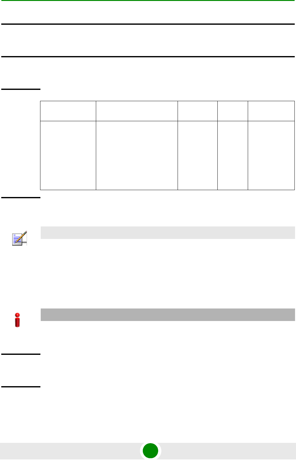
Chapter 3 - Operation and Administration of the Macro BTS Managing BSs
4Motion 497 System Manual
3.9 .2 De leting a BS
Run the following command to delete a BS:
npu(config)# no bs <(1 to 16777215 StepSize 1)>
Command
Syntax
npu(config)# bs <(1 to 16777215 StepSize 1)>
Privilege
Level
10
Syntax
Description Parameter Description Presence Default
Value
Possible
Values
<(1 to 16777215
StepSize 1)>
The unique ID (BSIDLSB) of
the BS. Must be unique in the
radio access network. A
number in the range from 1 to
16,777,215 (a 24-bit value
that can be represented as
A.B.C where A, B, C are from
0 to 255).
Mandatory N/A 1 to 16777215
Command
Modes
Global configuration mode
NOTE
The following examples are for bs configuration mode for bs-66053.
IMPORTANT
An associated bs (specified in an associated sector) cannot be deleted.
Command
Syntax
npu(config)# no bs <(1 to 16777215 StepSize 1)>
Privilege
Level
10
Chapter 3 - Operation and Administration of the Macro BTS Managing BSs
4Motion 498 System Manual
3.9 .3 Ma na ging BS Ge neral Parameters
The general parameters of a BS include the Operator ID and the BS Name.
After enabling the BS configuration mode, you can execute the following tasks:
Configure one or more of the general parameters (refer to Section 3.9.3.1).
Restore the default values of one or all of the general parameters (refer to
Section 3.9.3.2).
You can display configuration information for the general parameters of a selected
or all existing BSs (refer to Section 3.9.3.3).
3.9.3.1 Configuring BS General Parameters
From the BS configuration mode, run the following command:
npu(config-bs-66053)# general [operator-id <(1 to 16777215 StepSize 1)>]
[bs-name <string (32)>] [ul-def-rate {ctcQpskOneOverTwoTimesSix |
ctcQpskOneOverTwoTimesFour | ctcQpskOneOverTwoTimesTwo |
ctcQpskOneOverTwo | ctcQpskThreeOverFour | ctcQamSixteenOneOverTwo
| ctcQamSixteenThreeOverFour | ctcQamSixtyFourOneOverTwo |
ctcQamSixtyFourTwoOverThree | ctcQamSixtyFourThreeOverFour |
ctcQamSixtyFourFiveOverSix} ] [dl-def-rate-for-management
{ctcQpskOneOverTwoTimesSix | ctcQpskOneOverTwoTimesFour |
ctcQpskOneOverTwoTimesTwo | ctcQpskOneOverTwo |
ctcQpskThreeOverFour | ctcQamSixteenOneOverTwo |
ctcQamSixteenThreeOverFour | ctcQamSixtyFourOneOverTwo |
ctcQamSixtyFourTwoOverThree | ctcQamSixtyFourThreeOverFour |
Syntax
Description Parameter Description Presence Default
Value
Possible
Values
<(1 to 16777215
StepSize 1)>
The unique ID (BSIDLSB) of
the BS.
Mandatory N/A 1 to
16777215
Command
Modes
Global configuration mode
To configure the BS General Parameters:

Chapter 3 - Operation and Administration of the Macro BTS Managing BSs
4Motion 499 System Manual
ctcQamSixtyFourFiveOverSix} ] [dl-def-rate-for-data
{ctcQpskOneOverTwoTimesSix | ctcQpskOneOverTwoTimesFour |
ctcQpskOneOverTwoTimesTwo | ctcQpskOneOverTwo |
ctcQpskThreeOverFour | ctcQamSixteenOneOverTwo |
ctcQamSixteenThreeOverFour | ctcQamSixtyFourOneOverTwo |
ctcQamSixtyFourTwoOverThree | ctcQamSixtyFourThreeOverFour |
ctcQamSixtyFourFiveOverSix} ] [deployment {fix | mobile} ]
NOTE
After configuring at least one general BS parameter (see “Managing BS General Parameters” on
page 555), even when configured to its default value, all tables with no mandatory parameters are
created automatically, with all parameters set to their default value. Otherwise, for each of the
following tables you must enter the configuration mode and execute the Apply command before
exiting the configuration mode:
Power Control Levels and Policies
Control Traffic QoS Marking Rules
Ranging Parameters
Command
Syntax
npu(config-bs-66053)# general [operator-id <(1 to 16777215
StepSize 1)> ] [bs-name <string (32)> ] [ul-def-rate
{ctcQpskOneOverTwoTimesSix | ctcQpskOneOverTwoTimesFour |
ctcQpskOneOverTwoTimesTwo | ctcQpskOneOverTwo |
ctcQpskThreeOverFour | ctcQamSixteenOneOverTwo |
ctcQamSixteenThreeOverFour | ctcQamSixtyFourOneOverTwo |
ctcQamSixtyFourTwoOverThree | ctcQamSixtyFourThreeOverFour |
ctcQamSixtyFourFiveOverSix} ] [dl-def-rate-for-management
{ctcQpskOneOverTwoTimesSix | ctcQpskOneOverTwoTimesFour |
ctcQpskOneOverTwoTimesTwo | ctcQpskOneOverTwo |
ctcQpskThreeOverFour | ctcQamSixteenOneOverTwo |
ctcQamSixteenThreeOverFour | ctcQamSixtyFourOneOverTwo |
ctcQamSixtyFourTwoOverThree | ctcQamSixtyFourThreeOverFour |
ctcQamSixtyFourFiveOverSix} ] [dl-def-rate-for-data
{ctcQpskOneOverTwoTimesSix | ctcQpskOneOverTwoTimesFour |
ctcQpskOneOverTwoTimesTwo | ctcQpskOneOverTwo |
ctcQpskThreeOverFour | ctcQamSixteenOneOverTwo |
ctcQamSixteenThreeOverFour | ctcQamSixtyFourOneOverTwo |
ctcQamSixtyFourTwoOverThree | ctcQamSixtyFourThreeOverFour |
ctcQamSixtyFourFiveOverSix} ] [deployment {fix | mobile} ]

Chapter 3 - Operation and Administration of the Macro BTS Managing BSs
4Motion 500 System Manual
Privilege
Level
10
Syntax
Description Parameter Description Presence Default
Value
Possible
Values
[operator-id <(1 to
16777215 StepSize 1)>]
A unique operator
identifier. The same
Operator ID must be
used throughout the
radio access network.
(a 24-bit value that
can be represented as
A.B.C where A, B, C
are from 0 to 255)
Optional 16773929 1 to 16777215
[bs-name <string (32)>] BS name Optional empty
string
A string of up to
32 printable
characters.

Chapter 3 - Operation and Administration of the Macro BTS Managing BSs
4Motion 501 System Manual
[ul-def-rate
{ctcQpskOneOverTwoTi
mesSix |
ctcQpskOneOverTwoTi
mesFour |
ctcQpskOneOverTwoTi
mesTwo |
ctcQpskOneOverTwo |
ctcQpskThreeOverFour |
ctcQamSixteenOneOver
Two |
ctcQamSixteenThreeOv
erFour |
ctcQamSixtyFourOneOv
erTwo |
ctcQamSixtyFourTwoOv
erThree |
ctcQamSixtyFourThree
OverFour |
ctcQamSixtyFourFiveOv
erSix} ]
The uplink basic rate. Optional ctcQpskOn
eOverTwo
ctcQpskOne
OverTwoTi
mesSix
ctcQpskOne
OverTwoTi
mesFour
ctcQpskOne
OverTwoTi
mesTwo
ctcQpskOne
OverTwo
ctcQpskThre
eOverFour
ctcQamSixte
enOneOver
Two
ctcQamSixte
enThreeOv
erFour
ctcQamSixty
FourOneOv
erTwo
ctcQamSixty
FourTwoOv
erThree
ctcQamSixty
FourThree
OverFour
ctcQamSixty
FourFiveOv
erSix}

Chapter 3 - Operation and Administration of the Macro BTS Managing BSs
4Motion 502 System Manual
[dl-def-rate-for-manage
ment
{ctcQpskOneOverTwoTi
mesSix |
ctcQpskOneOverTwoTi
mesFour |
ctcQpskOneOverTwoTi
mesTwo |
ctcQpskOneOverTwo |
ctcQpskThreeOverFour |
ctcQamSixteenOneOver
Two |
ctcQamSixteenThreeOv
erFour |
ctcQamSixtyFourOneOv
erTwo |
ctcQamSixtyFourTwoOv
erThree |
ctcQamSixtyFourThree
OverFour |
ctcQamSixtyFourFiveOv
erSix} ]
The downlink basic
rate for unicast and
broadcast
management.
Optional ctcQpskOn
eOverTwo
ctcQpskOne
OverTwoTi
mesSix
ctcQpskOne
OverTwoTi
mesFour
ctcQpskOne
OverTwoTi
mesTwo
ctcQpskOne
OverTwo
ctcQpskThre
eOverFour
ctcQamSixte
enOneOver
Two
ctcQamSixte
enThreeOv
erFour
ctcQamSixty
FourOneOv
erTwo
ctcQamSixty
FourTwoOv
erThree
ctcQamSixty
FourThree
OverFour
ctcQamSixty
FourFiveOv
erSix}

Chapter 3 - Operation and Administration of the Macro BTS Managing BSs
4Motion 503 System Manual
[dl-def-rate-for-data
{ctcQpskOneOverTwoTi
mesSix |
ctcQpskOneOverTwoTi
mesFour |
ctcQpskOneOverTwoTi
mesTwo |
ctcQpskOneOverTwo |
ctcQpskThreeOverFour |
ctcQamSixteenOneOver
Two |
ctcQamSixteenThreeOv
erFour |
ctcQamSixtyFourOneOv
erTwo |
ctcQamSixtyFourTwoOv
erThree |
ctcQamSixtyFourThree
OverFour |
ctcQamSixtyFourFiveOv
erSix} ]
The downlink basic
rate for data.
Optional ctcQpskOn
eOverTwo
ctcQpskOne
OverTwoTi
mesSix
ctcQpskOne
OverTwoTi
mesFour
ctcQpskOne
OverTwoTi
mesTwo
ctcQpskOne
OverTwo
ctcQpskThre
eOverFour
ctcQamSixte
enOneOver
Two
ctcQamSixte
enThreeOv
erFour
ctcQamSixty
FourOneOv
erTwo
ctcQamSixty
FourTwoOv
erThree
ctcQamSixty
FourThree
OverFour
ctcQamSixty
FourFiveOv
erSix}
[deployment {fix
| mobile} ]
The type of
deployment in the
area served by the
BS. To support proper
handover, should be
set to fix only if mobile
MSs are not expected.
Optional fix fix
mobile
Command
Modes
bs configuration mode

Chapter 3 - Operation and Administration of the Macro BTS Managing BSs
4Motion 504 System Manual
3.9.3.2 Restoring Default Values for BS General Parameters
After enabling the BS configuration mode you can restore the default values for
one or all of the general BS parameters.
To restore one or all general BS parameters do their default value, run the
following command:
npu(config-bs-66053)# no general [operator-id] [bs-name]
[ul-def-rate-for-management] [dl-def-rate] [dl-def-rate-for-data]
[deployment]
You can restore one parameter to its default value by specifying only that
parameter. For example, to restore only the operator-id to its default value, run
the following command:
npu(config-bs-66053)# no general operator-id
The operator-id will be restored to its default value, while the other parameters
will remain unchanged.
To restore all parameters to their default value, run the following command:
npu(config-bs-66053)# no general
3.9.3.3 Displaying Configuration Information for BS General
Parameters
To display configuration information of the general parameters of a specific or all
BSs, run the following command:
NOTE
Refer to Section 3.9.3.1 for a description and default values of these parameters.
Command
Syntax
npu(config-bs-66053)# no general [operator-id] [bs-name]
[ul-def-rate] [dl-def-rate-for-management] [dl-def-rate-for-data]
[deployment]
Privilege
Level
10
Command
Modes
bs configuration mode

Chapter 3 - Operation and Administration of the Macro BTS Managing BSs
4Motion 505 System Manual
npu# show general bs [<(1 to 16777215 StepSize 1)>]
Specify the BS ID (1-16777215) of an existing BS if you want to display
configuration information for a particular BS. Do not specify values for this
parameter if you want to view configuration information for all existing BSs.
Command
Syntax
npu# show general bs [<(1 to 16777215 StepSize 1)> ]
Privilege
Level
1
Syntax
Description Parameter Description Presence Default
Value
Possible
Values
[<(1 to 16777215
StepSize 1)> ]
The BS ID
Specify a value for this
parameter if you want to
display the general
parameters of a specific BS.
Do not specify a value for this
parameter if you want to
display the general
parameters of all BSs.
Optional N/A 1-16777215
Display
Format
(for each
existing BS
if requested
for all BSs)
BSIDLSB :<value>
OperatorID :<value>
BSName :<value>
Defaultuplinkbasicrate :<value>
Defaultdownlinkbasicrateformanagement :<value>
Defaultdownlinkbasicratefordata :<value>
Deployment :<value>
Command
Modes
Global command mode

Chapter 3 - Operation and Administration of the Macro BTS Managing BSs
4Motion 506 System Manual
3.9 .4 Ma na ging Pow er Control Levels
1Enable the Power Control configuration mode (refer to Section 3.9.4.1)
2You can now execute any of the following tasks:
»Configure one or more of the Power Control parameters tables (refer to
Section 3.9.4.2)
»Restore the default values of parameters in one or more of the Power
Control parameters tables (refer to Section 3.9.4.3)
» Terminate the Power Control configuration mode (refer to Section 3.9.4.4)
In addition, you can, at any time, display configuration information for each of the
parameters tables (refer to Section 3.9.4.5).
3.9.4.1 Enabling the Power Control Configuration Mode
To configure the Power Control parameters, first enable the Power Control
configuration mode. Run the following command to enable the Power Control
configuration mode.
npu(config-bs-66053)# pwrctrl
The Power Control configuration mode is enabled, after which you can execute
any of the following tasks:
Configure one or more of the Power Control parameters tables (refer to
Section 3.9.4.2)
Restore the default values of parameters in one or more of the parameters
tables (refer to Section 3.9.4.3)
After executing the above tasks, you can terminate the Power Control
configuration mode (refer to Section 3.9.4.4) and return to the BS configuration
mode.
To configure the Power Control Levels:
Command
Syntax
npu(config-bs-66053)# pwrctrl

Chapter 3 - Operation and Administration of the Macro BTS Managing BSs
4Motion 507 System Manual
3.9.4.2 Configuring Power Control Parameters
After enabling the Power Control configuration mode you can configure the
following parameters tables:
Target Noise and Interference Level (refer to Section 3.9.4.2.1)
Required C/N Level (refer to Section 3.9.4.2.2)
3.9.4.2.1 Configuring Power Control Target Noise and Interference Level
Parameters
The Target Noise and Interference Level table enables defining the target limits for
various noise and interference levels.
To configure the Target Noise and Interference Levels, run the following command:
npu(config-bs-66053-pwrctrl)# nilevels [target-ni <(-130 to -110 StepSize 1)>]
[allowed-if-level {veryHigh | high | medium | low} ]
]
Privilege
Level
10
Command
Modes
bs configuration mode
NOTE
In the current release, the command for configuring Maximum EIRxP parameter,
npu(config-bs-66053-pwrctrl)# maxeirxp, is not applicable and should not be used. An attempt to
configure a value using this command will be ignored (value is taken from vendor file).
NOTE
An attempt to configure the cqi-ack-ranging parameter will be ignored. The value of this parameter
is set by internal logic.
Command
Syntax
npu(config-bs-66053-pwrctrl)# nilevels [target-ni <(-130 to -110
StepSize 1)> ] [allowed-if-level {veryHigh | high | medium | low}
]
Privilege
Level
10

Chapter 3 - Operation and Administration of the Macro BTS Managing BSs
4Motion 508 System Manual
3.9.4.2.2 Configuring the Power Control Required C/N Level Parameters
The Required C/N Levels table enables defining the Carrier to Noise Ratios
required for various types of transmissions.
To configure the Required C/N Levels, run the following command:
npu(config-bs-66053-pwrctrl)# requiredcnr [ack <(-20 to 50 StepSize 1)>] [cqi
<(-20 to 50 StepSize 1)>] [cdma <(-20 to 50 StepSize 1)>] [qpsk-1by2 <(-20 to 50
StepSize 1)>] [qpsk-3by4 <(-20 to 50 StepSize 1)>] [qam16-1by2 <(-20 to 50
StepSize 1)>] [qam16-3by4 <(-20 to 50 StepSize 1)>] [qam64-1by2 <(-20 to 50
StepSize 1)>] [qam64-2by3 <(-20 to 50 StepSize 1)>] [qam64-3by4 <(-20 to 50
StepSize 1)>] [qam64-5by6 <(-20 to 50 StepSize 1)>]
Syntax
Description Parameter Description Presence Default
Value
Possible
Values
[target-ni
<(-130 to -110
StepSize 1)> ]
Target Noise and
interference level for the
PUSC zone, in dBm.
Optional -127 -130 to -110 in
steps of 1
[allowed-if-level
{veryHigh | high |
medium | low} ]
Allowed Interference
Level: Correction of
maximum allowed UL
MCS based on
measured DL CINR.
Optional high veryHigh
high
medium
low
Command
Modes
bs power control configuration mode
Command
Syntax
npu(config-bs-66053-pwrctrl)# requiredcnr [ack <(-20 to 50
StepSize 1)> ] [cqi <(-20 to 50 StepSize 1)> ] [cdma <(-20 to 50
StepSize 1)> ] [qpsk-1by2 <(-20 to 50 StepSize 1)> ] [qpsk-3by4
<(-20 to 50 StepSize 1)> ] [qam16-1by2 <(-20 to 50 StepSize 1)> ]
[qam16-3by4 <(-20 to 50 StepSize 1)> ] [qam64-1by2 <(-20 to 50
StepSize 1)> ] [qam64-2by3 <(-20 to 50 StepSize 1)> ] [qam64-3by4
<(-20 to 50 StepSize 1)> ] [qam64-5by6 <(-20 to 50 StepSize 1)> ]
Privilege
Level
10

Chapter 3 - Operation and Administration of the Macro BTS Managing BSs
4Motion 509 System Manual
Syntax
Description Parameter Description Presence Default
Value
Possible
Values
[ack <(-20 to 50
StepSize 1)> ]
The C/N in dB required for
sending ACK, reported to the MS
for power control purposes.
Optional 7 -20 to 50
[cqi <(-20 to 50
StepSize 1)> ]
The C/N in dB required for
sending CQI, reported to the MS
for power control purposes.
Must be in the range from
requiredcnr-ack - 8 to
requiredcnr-ack + 7 (see ack
parameter above)
Optional 12 -20 to 50
[cdma <(-20 to 50
StepSize 1)> ]
The C/N in dB required for
transmitting CDMA, reported to
the MS for power control
purposes.
Must be in the range from
requiredcnr-cqi - 8 to
requiredcnr-cqi + 7 (see cqi
parameter above)
Optional 9 -20 to 50
[qpsk-1by2 <(-20 to
50 StepSize 1)> ]
The C/N in dB required for
transmitting using QPSK 1/2,
reported to the MS for power
control purposes.
Must be in the range from
requiredcnr-cdma - 16 to
requiredcnr-cdma + 14 (see cdma
parameter above)
Optional 13 -20 to 50
[qpsk-3by4<(-20 to
50 StepSize 1)> ]
The C/N in dB required for
transmitting using QPSK 3/4,
reported to the MS for power
control purposes.
Must be in the range from
requiredcnr-qpsk-1by2 - 16 to
requiredcnr-qpsk-1by2 + 14 (see
qpsk-1by2 parameter above)
Optional 16 -20 to 50

Chapter 3 - Operation and Administration of the Macro BTS Managing BSs
4Motion 510 System Manual
[qam16-1by2 <(-20
to 50 StepSize 1)> ]
The C/N in dB required for
transmitting using 16QAM 1/2,
reported to the MS for power
control purposes.
Must be in the range from
requiredcnr-qpsk-3by4 - 8 to
requiredcnr-qpsk-3by4 + 7 (see
qpsk-3by4 parameter above)
Optional 19 -20 to 50
[qam16-3by4 <(-20
to 50 StepSize 1)> ]
The C/N in dB required for
transmitting using 16QAM 3/4,
reported to the MS for power
control purposes.
Must be in the range from
requiredcnr-qam16-1by2 - 16 to
requiredcnr-qam16-1by2 + 14
(see qam16-1by2 parameter
above)
Optional 22 -20 to 50
[qam64-1by2 <(-20
to 50 StepSize 1)> ]
The C/N in dB required for
transmitting using 64QAM 1/2,
reported to the MS for power
control purposes.
Must be in the range from
requiredcnr-qam16-3by4 - 16 to
requiredcnr-qam16-3by4 + 14
(see qam16-3by4 parameter
above)
Optional 23 -20 to 50
[qam64-2by3 <(-20
to 50 StepSize 1)> ]
The C/N in dB required for
transmitting using 64QAM 2/3,
reported to the MS for power
control purposes.
Must be in the range from
requiredcnr-qam64-1by2 - 8 to
requiredcnr-qam64-1by2 + 7 (see
qam64-1by2 parameter above)
Optional 25 -20 to 50
[qam64-3by4 <(-20
to 50 StepSize 1)> ]
The C/N in dB required for
transmitting using 64QAM 3/4,
reported to the MS for power
control purposes.
Must be in the range from
requiredcnr-qam64-2by3 - 8 to
requiredcnr-qam54-2by3 + 7 (see
qam54-2by3 parameter above)
Optional 26 -20 to 50
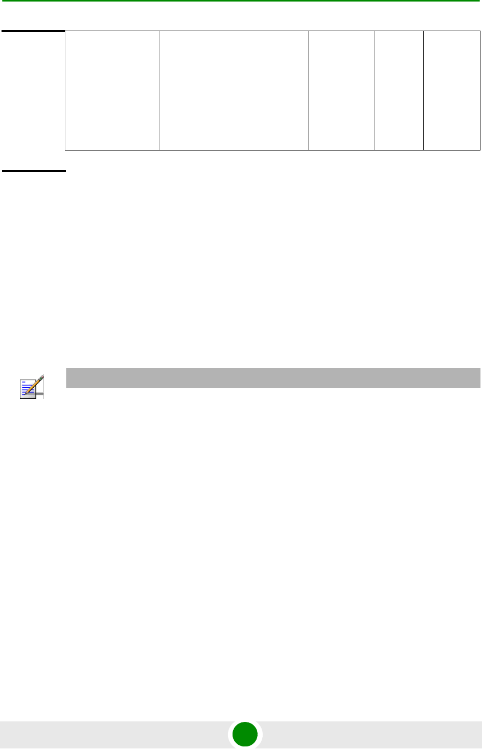
Chapter 3 - Operation and Administration of the Macro BTS Managing BSs
4Motion 511 System Manual
3.9.4.3 Restoring Default Values for Power Control Configuration
Parameters
After enabling the Power Control configuration mode you can restore the default
values for parameters in the following parameters tables:
Noise and Interference Level (refer to Section 3.9.4.3.1)
Required C/N Level (refer to Section 3.9.4.3.2)
3.9.4.3.1 Restoring the Default Values of Power Control Target Noise and
Interference Level Parameters
To restore one or all of the Target Noise and Interference Level parameters to their
default values, run the following command:
npu(config-bs-66053-pwrctrl)# no nilevels [target-ni] [allowed-if-level]
You can restore only one parameter to its default values by specifying only that
parameter. For example, to restore only the target-ni to the default value, run the
following command:
npu(config-bs-66053-pwrctrl)# no nilevels target-ni
The parameter will be restored to its default value, while the other parameter will
remain unchanged.
[qam64-5by6 <(-20
to 50 StepSize 1)> ]
he C/N in dB required for
transmitting using 64QAM 5/6,
reported to the MS for power
control purposes.
Must be in the range from
requiredcnr-qam64-3by4 - 8 to
requiredcnr-qam64-3by4 + 7 (see
qam64-3by4 parameter above)
Optional 28 -20 to 50
Command
Modes
bs power control configuration mode
NOTE
In the current release, the command for restoring the default value for the Maximum EIRxP
parameter, npu(config-bs-66053-pwrctrl)# no maxeirxp, is not applicable and should not be used.
An attempt to restore the value to a default value using this command will be ignored (value is taken
from vendor file).

Chapter 3 - Operation and Administration of the Macro BTS Managing BSs
4Motion 512 System Manual
To restore all Target Noise and Interference Level parameters to their default
value, run the following command:
npu(config-bs-66053-pwrctrl)# no nilevels
3.9.4.3.2 Restoring the Default Values of Power Control Required C/N Level
Parameters
To restore some or all of the Required C/N Levels parameters to their default
values, run the following command:
npu(config-bs-66053-pwrctrl)# no requiredcnr [ack] [cqi] [cdma] [qpsk-1by2]
[qpsk-3by4] [qam16-1by2] [qam16-3by4] [qam64-1by2] [qam64-2by3]
[qam64-3by4] [qam64-5by6]
You can restore only some parameters to their default values by specifying only
those parameter. For example, to restore only the ack and cqi parameters to the
default values, run the following command:
npu(config-bs-66053-pwrctrl)# no requiredcnr ack cqi
These parameters will be restored to their default value, while the other
parameters will remain unchanged.
To restore all Required C/N Levels parameters to their default value, run the
following command:
npu(config-bs-66053-pwrctrl)# no requiredcnr
NOTE
Refer to Section 3.9.4.2.1 for a description and default values of these parameters.
Command
Syntax
npu(config-bs-66053-pwrctrl)# no nilevels [target-ni]
[allowed-if-level]
Privilege
Level
10
Command
Modes
bs power control configuration mode
NOTE
Refer to Section 3.9.4.2.2 for a description and default values of these parameters.

Chapter 3 - Operation and Administration of the Macro BTS Managing BSs
4Motion 513 System Manual
3.9.4.4 Terminating the Power Control Configuration Mode
Run the following command to terminate the Power Control configuration mode:
npu(config-bs-66053-pwrctrl)# exit
3.9.4.5 Displaying Configuration Information for Power Control
Parameters
You can display the current configuration information for the following
parameters tables:
Noise and Interference Level (refer to Section 3.9.4.5.1)
Maximum EIRxP (refer to Section 3.9.4.5.2)
Required C/N Level (refer to Section 3.9.4.5.3)
All (refer to Section 3.9.4.5.4)
Command
Syntax
npu(config-bs-66053-pwrctrl)# no requiredcnr [ack ] [cqi ] [cdma ]
[qpsk-1by2 ] [qpsk-3by4 ] [qam16-1by2 ] [qam16-3by4 ] [qam64-1by2
] [qam64-2by3 ] [qam64-3by4 ] [qam64-5by6 ]
Privilege
Level
10
Command
Modes
bs power control configuration mode
Command
Syntax
npu(config-bs-66053-pwrctrl)# exit
Privilege
Level
10
Command
Modes
bs power control configuration mode

Chapter 3 - Operation and Administration of the Macro BTS Managing BSs
4Motion 514 System Manual
3.9.4.5.1 Displaying Configuration Information for Power Control Target Noise
and Interference Level Parameters
To display configuration for the Power Control Target Noise and Interference Level
parameters, run the following command:
npu# show pwrctrl-nilevels bs [<(1 to 16777215 StepSize 1)
Specify the BS ID if you want to display configuration for a particular BS. For
example, to display the Power Control Target Noise and Interference Level
parameters of BS 66053, run the following command:
npu# show pwrctrl-nilevels bs 66053
Do not specify this parameter if you want to view configuration information for all
existing BSs. To display information for all BSs, run the following command:
npu# show pwrctrl-nilevels bs
Command
Syntax
npu# show pwrctrl-nilevels bs [<(1 to 16777215 StepSize 1)
Privilege
Level
1
Syntax
Description Parameter Description Presence Default
Value
Possible
Values
<(1 to 16777215
StepSize 1)>
The BS ID
Specify a value for this
parameter if you want to
display the Target Noise and
Interference Level
parameters of a specific BS.
Do not specify a value for this
parameter if you want to
display the Target Noise and
Interference Level
parameters of all BSs.
Optional N/A 1-16777215

Chapter 3 - Operation and Administration of the Macro BTS Managing BSs
4Motion 515 System Manual
3.9.4.5.2 Displaying Configuration Information for Power Control Maximum
EIRxP
The Maximum EIRxP parameter defines the maximum effective isotropic received
power at the BS for Initial ranging.
In the current release this parameter cannot be configured and is set by the value
in the vendor parameters file.
To display configuration for the Power Control Maximum EIRxP parameter, run
the following command:
npu# show pwrctrl-maxeirxp bs [<(1 to 16777215 StepSize 1)
Specify the BS ID if you want to display configuration for a particular BS. For
example, to display the Power Control Maximum EIRxP parameter of BS 66053,
run the following command:
npu# show pwrctrl-maxeirxp bs 66053
Do not specify this parameter if you want to view configuration information for all
existing BSs. To display information for all BSs, run the following command:
npu# show pwrctrl-maxeirxp bs
Display
Format
(for each
existing BS
if requested
for all BSs)
BSIDLSB :<value>
TargetNi :<value>
AllowedIfLevel :<value>
Command
Modes
Global command mode
Command
Syntax
npu# show pwrctrl-maxeirxp bs [<(1 to 16777215 StepSize 1)
Privilege
Level
1

Chapter 3 - Operation and Administration of the Macro BTS Managing BSs
4Motion 516 System Manual
3.9.4.5.3 Displaying Configuration Information for Power Control Required C/N
Level Parameters
To display configuration for the Power Control Required C/N Level parameters,
run the following command:
npu# show pwrctrl-requiredcnr bs [<(1 to 16777215 StepSize 1)
Specify the BS ID if you want to display configuration for a particular BS. For
example, to display the Power Control Required C/N Level parameters of BS
66053, run the following command:
npu# show pwrctrl-requiredcnr bs 66053
Do not specify this parameter if you want to view configuration information for all
existing BSs. To display information for all BSs, run the following command:
npu# show pwrctrl-requiredcnr bs
Syntax
Description Parameter Description Presence Default
Value
Possible
Values
<(1 to 16777215
StepSize 1)>
The BS ID
Specify a value for this
parameter if you want to
display the Maximum EIRxP
parameter of a specific BS.
Do not specify a value for this
parameter if you want to
display the Maximum EIRxP
parameter of all BSs.
Optional N/A 1-16777215
Display
Format
(for each
existing BS
if requested
for all BSs)
BSIDLSB :<value>
MaxEIRxP :<value>
Command
Modes
Global command mode

Chapter 3 - Operation and Administration of the Macro BTS Managing BSs
4Motion 517 System Manual
Command
Syntax
npu# show pwrctrl-requiredcnr bs [<(1 to 16777215 StepSize 1)
Privilege
Level
1
Syntax
Description Parameter Description Presence Default
Value
Possible
Values
<(1 to 16777215
StepSize 1)>
The BS ID
Specify a value for this
parameter if you want to
display the Required C/N
Level parameters of a specific
BS. Do not specify a value for
this parameter if you want to
display the Required C/N
Level parameters of all BSs.
Optional N/A 1-16777215
Display
Format
(for each
existing BS
if requested
for all BSs)
BSIDLSB :<value>
RequiredCNRforACK :<value>
RequiredCNRforCQI :<value>
RequiredCNRforCDMA :<value>
RequiredCNRforQPSK1/2 :<value>
RequiredCNRforQPSK3/4 :<value>
RequiredCNRfor16QAM1/2 :<value>
RequiredCNRfor16QAM3/4 :<value>
RequiredCNRfor64QAM1/2 :<value>
RequiredCNRfor64QAM2/3 :<value>
RequiredCNRfor64QAM3/4 :<value>
RequiredCNRfor64QAM5/6 :<value>
Command
Modes
Global command mode

Chapter 3 - Operation and Administration of the Macro BTS Managing BSs
4Motion 518 System Manual
3.9.4.5.4 Displaying Configuration Information for All Power Control
Parameters
To display configuration for all Power Control parameters, run the following
command:
npu# show pwrctrl-all bs [<(1 to 16777215 StepSize 1)
Specify the BS ID if you want to display configuration for a particular BS. For
example, to display all Power Control parameters of BS 66053, run the following
command:
npu# show pwrctrl-all bs 66053
Do not specify this parameter if you want to view configuration information for all
existing BSs. To display information for all BSs, run the following command:
npu# show pwrctrl-all bs
Command
Syntax
npu# show pwrctrl-all bs [<(1 to 16777215 StepSize 1)
Privilege
Level
10
Syntax
Description Parameter Description Presence Default
Value
Possible
Values
<(1 to 16777215
StepSize 1)>
The BS ID
Specify a value for this
parameter if you want to
display all Power Control
parameters of a specific BS.
Do not specify a value for this
parameter if you want to
display all Power Control
parameters of all BSs.
Optional N/A 1-16777215
Command
Modes
Global command mode

Chapter 3 - Operation and Administration of the Macro BTS Managing BSs
4Motion 519 System Manual
3.9 .5 Ma na ging BS Feedback Allocation Parameter
After enabling the BS configuration mode, you can execute the following tasks:
Configure the Feedback Allocation parameter (refer to Section 3.9.5.1).
Restore the default values of the Feedback Allocation parameter (refer to
Section 3.9.5.2).
You can display configuration information for the Feedback Allocation parameter
of a selected or all existing BSs (refer to Section 3.9.5.3).
3.9.5.1 Configuring Feedback Allocation Parameter
From the BS configuration mode, run the following command:
npu(config-bs-66053)# feedbackalloc [ir-cdma <(1 to 1 StepSize 1) |
(2 to 2 StepSize 1) | (4 to 4 StepSize 1) | (6 to 6 StepSize 1) | (8
to 8 StepSize 1) | (10 to 10 StepSize 1)> ]
To configure the Feedback Allocation Parameter:
Command
Syntax
npu(config-bs-66053)# feedbackalloc [ir-cdma <(1 to 1 StepSize 1)
| (2 to 2 StepSize 1) | (4 to 4 StepSize 1) | (6 to 6 StepSize 1)
| (8 to 8 StepSize 1) | (10 to 10 StepSize 1)> ]
Privilege
Level
10
Syntax
Description Parameter Description Presence Default
Value
Possible
Values
[ir-cdma <<(1 to 1
StepSize 1) | (2 to 2
StepSize 1) | (4 to 4
StepSize 1) | (6 to 6
StepSize 1) | (8 to 8
StepSize 1) | (10 to
10 StepSize 1)>> ]
The period of IR CDMA
allocations, in frames.
In the current release the
actual value is always 2,
regardless of the
configured value.
Optional 2 1, 2, 4, 6, 8,
10.

Chapter 3 - Operation and Administration of the Macro BTS Managing BSs
4Motion 520 System Manual
3.9.5.2 Restoring the Default Values of the Feedback Allocation
Parameter
To restore the ir-cdma non-mandatory parameter to the default values, run the
following command:
npu(config-bs-66053)# no feedbackalloc [ir-cdma]
To restore the ir-cdma parameter to the default value, run any of the following
commands:
npu(config-bs-66053)# no feedbackalloc ir-cdma
npu(config-bs-66053)# no feedbackalloc
3.9.5.3 Displaying Configuration Information for the Feedback
Allocation Parameter
To display configuration information for Feedback Allocation parameter, run the
following command:
npu# show feedbackalloc bs [<(1 to 16777215 StepSize 1)
Specify the BS ID if you want to display configuration for a particular BS. For
example, to display the Feedback Allocation parameter of BS 66053, run the
following command:
npu# show feedbackalloc bs 66053
Command
Modes
bs configuration mode
NOTE
Refer to Section 3.9.5.1 for a description and default values of this parameter.
Command
Syntax
npu(config-bs-66053)# no feedbackalloc [ir-cdma ]
Privilege
Level
10
Command
Modes
bs configuration mode

Chapter 3 - Operation and Administration of the Macro BTS Managing BSs
4Motion 521 System Manual
Do not specify this parameter if you want to view configuration information for all
existing BSs. To display information for all BSs, run the following command:
npu# show feedbackalloc bs
3.9 .6 Ma na ging N e ighbor Adve rtisement
Pa ra m e t e r s
After enabling the BS configuration mode, you can execute the following tasks:
Command
Syntax
npu# show feedbackalloc bs [<(1 to 16777215 StepSize 1)
Privilege
Level
1
Syntax
Description Parameter Description Presence Default
Value
Possible
Values
<(1 to 16777215
StepSize 1)>
The BS ID
Specify a value for this
parameter if you want to
display Feedback Allocation
parameter of a specific BS.
Do not specify a value for this
parameter if you want to
display Feedback Allocation
parameter of all BSs.
Optional N/A 1-16777215
Display
Format
(for each
existing BS
if requested
for all BSs)
BSIDLSB :<value>
IRCDMAAllocationsPeriod(frames) :<value>
Command
Modes
Global command mode

Chapter 3 - Operation and Administration of the Macro BTS Managing BSs
4Motion 522 System Manual
Configure one or more of the Neighbor Advertisement parameters (refer to
Section 3.9.6.1).
Restore the default values of one or all of the Neighbor Advertisement
parameters (refer to Section 3.9.6.2).
You can display configuration information for the Neighbor Advertisement
parameters of a selected or all existing BSs (refer to Section 3.9.6.3).
3.9.6.1 Configuring Neighbor Advertisement Parameters
From the BS configuration mode, run the following command:
npu(config-bs-66053)# nbradvertise [triggersetup <(0 to 100 StepSize 0.1)>]
3.9.6.2 Restoring the Default Values of Neighbor Advertisement
Parameter
Since there is only one Neighbor Advertisement parameter, run any of the
following commands to restore it to the default value:
npu(config-bs-66053)# no nbradvertise
To configure the Neighbor Advertisement Parameters:
Command
Syntax
npu(config-bs-66053)# nbradvertise [triggersetup <(0 to 100
StepSize 0.1)> ]
Privilege
Level
10
Syntax
Description Parameter Description Presence Default
Value
Possible
Values
[triggersetup <(0 to 100
StepSize 0.1)> ]
The periodic NBRADV
transmission interval, in
seconds
Optional 10 0 - 100 in
steps of 0.1
Command
Modes
bs configuration mode

Chapter 3 - Operation and Administration of the Macro BTS Managing BSs
4Motion 523 System Manual
npu(config-bs-66053)# no nbradvertise triggersetup
3.9.6.3 Displaying Configuration Information for Neighbor
Advertisement Parameters
To display configuration information for the Neighbor Advertisement parameter,
run the following command:
npu# show nbradvertise bs [<(1 to 16777215 StepSize 1)
Specify the BS ID if you want to display configuration for a particular BS. For
example, to display the Neighbor Advertisement parameters of BS 66053, run the
following command:
npu# show nbradvertise bs 66053
Do not specify this parameter if you want to view configuration information for all
existing BSs. To display information for all BSs, run the following command:
npu# show nbradvertise bs
NOTE
Refer to Section 3.9.6.1 for a description and default values of these parameters.
Command
Syntax
npu(config-bs-66053)# no nbradvertise [triggersetup]
Privilege
Level
10
Command
Modes
bs configuration mode
Command
Syntax
npu# show nbradvertise bs [<(1 to 16777215 StepSize 1)
Privilege
Level
1

Chapter 3 - Operation and Administration of the Macro BTS Managing BSs
4Motion 524 System Manual
3.9 .7 Ma na ging Triggers Parameters
After enabling the BS configuration mode, you can configure one or more of the
Triggers parameters (refer to Section 3.9.7.1).
You can display configuration information for the Triggers parameters of a
selected or all existing BSs (refer to Section 3.9.7.2).
3.9.7.1 Configuring Triggers Parameters
From the BS configuration mode, run the following command:
npu(config-bs-66053)# triggers-<trigger-name> <trigger-range>
Each Trigger is configured separately. This is the general structure of the
command.
Syntax
Description Parameter Description Presence Default
Value
Possible
Values
<(1 to 16777215
StepSize 1)>
The BS ID
Specify a value for this
parameter if you want to
display Neighbor
Advertisement parameters of
a specific BS. Do not specify
a value for this parameter if
you want to display Neighbor
Advertisement parameters of
all BSs.
Optional N/A 1-16777215
Display
Format
(for each
existing BS
if requested
for all BSs)
BSIDLSB :<value>
PeriodicInterval :<value>
Command
Modes
Global command mode
To configure the Triggers Parameters:

Chapter 3 - Operation and Administration of the Macro BTS Managing BSs
4Motion 525 System Manual
Command
Syntax
npu(config-bs-66053)# triggers-<trigger-name> <trigger-range>
Privilege
Level
10
Syntax
Description Parameter Description Presence Default
Value
Possible
Values
<trigger-name> The Trigger name. Mandatory N/A See
Table 3-2
9 below
<trigger-value> Defines the threshold
value for the Trigger.
Mandatory N/A See
Table 3-2
9 below
Command
Modes
bs configuration mode
Table 3-29: Trigger Names and Possible Value Ranges
Trigger Name Trigger Condition Action Possible Values
triggers-scnreq-cinr-min The C/N at the Serving BS is
below the Trigger threshold
(in dB)
Scan Request -64 to 63.5 in steps of 0.5
triggers-scnreq-rssi-min The RSSI at the Serving BS is
below the Trigger threshold
(in Bm)
-103.75 to -40 in steps of 0.25
triggers-scnreq-rtd-max The Serving BS distance from
the MS (calculated by
measuring the round trip
delay) is above the Trigger
threshold (in meter)
0-3400 in steps of 50 if BS BW
is 10 MHz, 0-6800 in steps of
50 if BS BW is 5 MHz, 0-4800
in steps of 50 if BS BW is 7
MHz

Chapter 3 - Operation and Administration of the Macro BTS Managing BSs
4Motion 526 System Manual
3.9.7.2 Displaying Configuration Information for Triggers
Parameters
To display configuration information for Triggers parameters, run the following
command:
npu# show triggers bs [<(1 to 16777215 StepSize 1)> TrigName {scnReqCinrMin
| scnReqRssiMin | scnReqRtdMax | hoReqCinrMaxNbs | hoReqRssiMaxNbs |
hoReqCinrMargin | hoReqRssiMargin | hoReqRtdMax | hoReqCinrMinSbs |
hoReqRssiMinSbs}]
Specify the BS ID and Trigger name if you want to display configuration for a
particular Trigger. For example, to display the scnReqCinrMin parameters of BS
66053, run the following command:
npu# show triggers bs 66053 TrigName scnReqCinrMin
triggers-horeq-cinr-margin The C/N at the Neighbor BS
minus the C/N at the Serving
BS is above the Trigger
threshold (in dB)
Handover
Request
-64 to 63.5 in steps of 0.5
triggers-horeq-cinr-max The C/N at the Neighbor BS is
above the Trigger threshold
(in dB)
-64 to 63.5 in steps of 0.5
triggers-horeq-cinr-min The C/N at the Serving BS is
below the Trigger threshold
(in dB)
-64 to 63.5 in steps of 0.5
triggers-horeq-rssi-margin The RSSI at the Neighbor BS
minus the RSSI at the Serving
BS is above the Trigger
threshold (in dBm)
-32 to 31.75 in steps of 0.25
triggers-horeq-rssi-max The RSSI at the Neighbor BS
is above the Trigger threshold
(in dBm)
-103.75 to -40 in steps of 0.25
triggers-horeq-rssi-min The RSSI at the Serving BS is
below the Trigger threshold
(in dBm)
-103.75 to -40 in steps of 0.25
triggers-horeq-rtd-max The Serving BS distance from
the MS (calculated by
measuring the round trip
delay) is above the Trigger
threshold (in meter)
0-3400 in steps of 50 if BS BW
is 10 MHz, 0-6800 in steps of
50 if BS BW is 5 MHz, 0-4800
in steps of 50 if BS BW is 7
MHz
Table 3-29: Trigger Names and Possible Value Ranges
Trigger Name Trigger Condition Action Possible Values

Chapter 3 - Operation and Administration of the Macro BTS Managing BSs
4Motion 527 System Manual
Do not specify these parameters if you want to view configuration information for
all existing BSs. To display information for all BSs, run the following command:
npu# show triggers bs
Command
Syntax
npu# show triggers bs [<(1 to 16777215 StepSize 1)> TrigName {scnReqCinrMin |
scnReqRssiMin | scnReqRtdMax | hoReqCinrMaxNbs | hoReqRssiMaxNbs | hoReqCinrMargin |
hoReqRssiMargin | hoReqRtdMax | hoReqCinrMinSbs | hoReqRssiMinSbs} ]
Privilege
Level
1
Syntax
Description Parameter Description Presence Default
Value
Possible Values
<(1 to 16777215
StepSize 1)>
The BS ID
Specify a value for
this parameter if you
want to display a
specific Trigger of a
specific BS. Do not
specify a value for
this parameter if you
want to display all
Triggers parameters
of all BSs.
Optional N/A 1-16777215
TrigName
{scnReqCinrMin |
scnReqRssiMin |
scnReqRtdMax |
hoReqCinrMaxNbs |
hoReqRssiMaxNbs |
hoReqCinrMargin |
hoReqRssiMargin |
hoReqRtdMax |
hoReqCinrMinSbs |
hoReqRssiMinSbs} ]
The Trigger name
Specify only if you
want to display a
specific Trigger of a
specific BS. Do not
specify if you want to
display all Triggers
parameters of all BSs
scnReqCinrMin
scnReqRssiMin
scnReqRtdMax
hoReqCinrMaxNbs
hoReqRssiMaxNbs
hoReqCinrMargin
hoReqRssiMargin
hoReqRtdMax
hoReqCinrMinSbs
hoReqRssiMinSbs}
Chapter 3 - Operation and Administration of the Macro BTS Managing BSs
4Motion 528 System Manual
3.9 .8 Ma na ging Scan Ne gotiation Parameters
After enabling the BS configuration mode, you can execute the following tasks:
Configure one or more of the Scan Negotiation parameters (refer to
Section 3.9.8.1).
Restore the default values of some or all of the Scan Negotiation parameters
(refer to Section 3.9.8.2).
You can display configuration information for the Scan Negotiation parameters of
a selected or all existing BSs (refer to Section 3.9.8.3).
3.9.8.1 Configuring Scan Negotiation Parameters
From the BS configuration mode, run the following command:
npu(config-bs-66053)# scanning [enable-modify {true | false}]
Display
Format
(for a
selected
Trigger)
BSIDLSB :<value>
scnReqRssiMin :<value>
Command
Modes
Global command mode
To configure the Scan Negotiation Parameters:
Command
Syntax
npu(config-bs-66053)# scanning [enable-modify {true | false} ]
Privilege
Level
10
Chapter 3 - Operation and Administration of the Macro BTS Managing BSs
4Motion 529 System Manual
3.9.8.2 Restoring the Default Value of Scan Negotiation Parameters
To restore the Scan Negotiation enable-modify parameter to the default value, run
the following command:
npu(config-bs-66053)# no scanning [enable-modify]
3.9.8.3 Displaying Configuration Information for Scan Negotiation
Parameters
To display configuration information for Scan Negotiation parameters, run the
following command:
Syntax
Description Parameter Description Presence Default
Value
Possible
Values
[enable-modify {TRUE
| FALSE} ]
Determines whether the
BS will modify unfeasible
scan profiles requested by
MSs.
Note: If TRUE the BS will
modify unfeasible scan
profile requests and if
FALSE the BS will deny
the requests.
Optional true true
false
Command
Modes
bs configuration mode
NOTE
Refer to Section 3.9.8.1 for a description and default value of this parameter.
Command
Syntax
npu(config-bs-66053)# no scanning [enable-modify ][
Privilege
Level
10
Command
Modes
bs configuration mode

Chapter 3 - Operation and Administration of the Macro BTS Managing BSs
4Motion 530 System Manual
npu# show scanning bs [<(1 to 16777215 StepSize 1)
Specify the BS ID if you want to display configuration for a particular BS. For
example, to display the Scan Negotiation parameters of BS 66053, run the
following command:
npu# show scanning bs 66053
Do not specify this parameter if you want to view configuration information for all
existing BSs. To display information for all BSs, run the following command:
npu# show scanning bs
Command
Syntax
npu# show scanning bs [<(1 to 16777215 StepSize 1)
Privilege
Level
1
Syntax
Description Parameter Description Presence Default
Value
Possible
Values
<(1 to 16777215
StepSize 1)>
The BS ID
Specify a value for this
parameter if you want to
display Scan Negotiation
parameters of a specific BS.
Do not specify a value for this
parameter if you want to
display Scan Negotiation
parameters of all BSs.
Optional N/A 1-16777215
Display
Format
(for each
existing BS
if requested
for all BSs)
BSIDLSB :<value>
EnableModifyProfile :<true/false>
Command
Modes
Global command mode

Chapter 3 - Operation and Administration of the Macro BTS Managing BSs
4Motion 531 System Manual
3.9 .9 Ma na ging N e ighbor BSs
1Enable the Neighbor BS configuration mode for the selected Neighbor BS (refer
to Section 3.9.9.1)
2You can now execute any of the following tasks:
»Configure one or more of the parameters tables of the Neighbor BS (refer to
Section 3.9.9.2)
»Restore the default values of parameters in one or more of the parameters
tables of the Neighbor BS (refer to Section 3.9.9.3)
» Terminate the Neighbor BS configuration mode (refer to Section 3.9.9.5)
In addition, you can, at any time, display configuration information for each of the
parameters tables of the Neighbor BS (refer to Section 3.9.9.7) or delete an
existing Neighbor BS (refer to Section 3.9.9.6).
3.9.9.1 Enabling the Neighbor BS Configuration Mode\Creating a
Neighbor BS
To configure the parameters of a Neighbor BS, first enable the Neighbor BS
configuration mode for the specific Neighbor BS. Run the following command to
enable the Neighbor BS configuration mode. You can also use this command to
create a new Neighbor BS.
npu(config-bs-66053)# nbr <(1 to 16777215 StepSize 1)>
Note that for a new Neighbor BS this command only defines the Neighbor BS ID,
and that the Neighbor BS is not fully created until completing configuration of all
mandatory parameters and executing the apply command (must be executed
before exiting the Neighbor BS configuration mode). Also when updating an
existing Neighbor BS, the apply command must be executing prior to termination
the Neighbor BS configuration mode.
For example, to define a new Neighbor BS with a BS ID 66055, or to enable the
configuration mode for Neighbor BS 66055, run the following command:
npu(config-bs-66053)# nbr 66055
To configure a Neighbor BS:

Chapter 3 - Operation and Administration of the Macro BTS Managing BSs
4Motion 532 System Manual
If you use this command to create a new Neighbor BS, the configuration mode for
this Neighbor BS is automatically enabled, after which you can execute any of the
following tasks:
Configure one or more of the parameters tables of the Neighbor BS (refer to
Section 3.9.9.2)
Restore the default values of parameters in one or more of the parameters
tables of the Neighbor BS (refer to Section 3.9.9.3)
After executing the above tasks, you can terminate the Neighbor BS configuration
mode (refer to Section 3.9.9.5) and return to the BS configuration mode.
Note that for properly completing the configuration of a Neighbor BS the apply
command must be executed prior to exiting the Neighbor BS configuration mode.
For example, to define Neighbor BS 66055 for bs-68000, run the following
command:
npu(config-bs-66053)# nbr 68000
Command
Syntax
npu(config-bs-66053)# nbr <(1 to 16777215 StepSize 1)>
Privilege
Level
10
Syntax
Description Parameter Description Presence Default
Value
Possible
Values
nbr <(1 to 16777215
StepSize 1)>
The BS ID (BSIDLSB) of the
Neighbor BS
Mandatory 1 - 16777215
Command
Modes
bs configuration mode
NOTE
The following examples are for Neighbor BS configuration mode for bs-66053, neighbor bs (nbr)
68000.

Chapter 3 - Operation and Administration of the Macro BTS Managing BSs
4Motion 533 System Manual
3.9.9.2 Configuring Neighbor BS Parameters
After enabling the Neighbor BS configuration mode you can configure the
following parameters tables:
General (refer to Section 3.9.9.2.1)
Required C/N Level (refer to Section 3.9.9.2.2)
Triggers (refer to Section 3.9.9.2.3)
Specific BS Triggers (refer to Section 3.9.9.2.4
3.9.9.2.1 Configuring General Neighbor BS Parameters
The General Neighbor BS Parameters table enables defining the general
parameters of the Neighbor BS.
To configure the General Neighbor BS parameters, run the following command:
npu(config-bs-66053-nbr-68000)# general [syncind {unsynchronized |
timeSynchronized | timeAndFrequencySynchronized}] [eirp <(-128 to 127
StepSize 1)>] [bw {fiveMHz | tenMHz | sevenMHz}] [feedbackzone-permbase <(0 to
69 StepSize 1)>] [ucd-configchangecount <(0 to 255 StepSize 1)>]
[dcd-configchangecount <(0 to 255 StepSize 1)>] [eirx-pir-max <(-140 to -40
StepSize 1)>] [frequency <(2022.5 to 2217.5 StepSize 0.125) | (2302.5 to 2397.5
StepSize 0.125) | (2487.5 to 2687.5 StepSize 0.125) | (3302.5 to 3397.5 StepSize
0.125) | (3402.5 to 3597.5 StepSize 0.125) | (3602.5 to 3797.5 StepSize 0.125)>]
[preamble-idx <(0 to 255 StepSize 1)>] [paging-grp-id <(0 to 65535 StepSize 1)> ]
[nbr-strt-rng-codes <(0 to 255 StepSize 1)> ] [bsNeighborBsDlDataMIMOMode
{matrixAorB | beamforming} ]
IMPORTANT
After completing the Neighbor BS configuration, do not forget to execute the apply command before
exiting the Neighbor BS configuration mode:
npu(config-bs-66053-nbr-68000)# apply
IMPORTANT
When creating a new Neighbor BS, all mandatory Neighbor BS General parameters must be
configured.

Chapter 3 - Operation and Administration of the Macro BTS Managing BSs
4Motion 534 System Manual
Command
Syntax
npu(config-bs-66053-nbr-68000)# general [syncind {unsynchronized |
timeSynchronized | timeAndFrequencySynchronized} ] [eirp <(-128 to
127 StepSize 1)> ] [bw {fiveMHz | tenMHz | sevenMHz} ]
[feedbackzone-permbase <(0 to 69 StepSize 1)> ]
[ucd-configchangecount <(0 to 255 StepSize 1)>]
[dcd-configchangecount <(0 to 255 StepSize 1)> ] [eirx-pir-max
<(-140 to -40 StepSize 1)> ] [frequency <(2022.5 to 2217.5
StepSize 0.125) | (2302.5 to 2397.5 StepSize 0.125) | (2487.5 to
2687.5 StepSize 0.125) | (3302.5 to 3397.5 StepSize 0.125) |
(3402.5 to 3597.5 StepSize 0.125) | (3602.5 to 3797.5 StepSize
0.125)> ] [preamble-idx <(0 to 255 StepSize 1)> ] [paging-grp-id
<(0 to 65535 StepSize 1)> ] [nbr-strt-rng-codes <(0 to 255
StepSize 1)> ] [bsNeighborBsDlDataMIMOMode {matrixAorB |
beamforming} ]
Privilege
Level
10
Syntax
Description Parameter Description Presence Default
Value
Possible Values
[syncind
{unsynchronized |
timeSynchronized |
timeAndFrequency
Synchronized} ]
Time/Frequency
synchronization
indicator.
In the current release
should always be set to
timeAndFrequencySyn
chronized.
Optional timeAndFr
equencySy
nchronized
unsynchronized
timeSynchronized
timeAndFrequency
Synchronized
[eirp <(-128 to 127
StepSize 1)> ]
Neighbor BS EIRP Mandatory
When
creating a
new
Neighbor
BS.
N/A -128 to 127

Chapter 3 - Operation and Administration of the Macro BTS Managing BSs
4Motion 535 System Manual
[bw {fiveMHz |
tenMHz |
sevenMHz} ]
The bandwidth of
neighbor BS.
Should be taken from
Baseband bandwidth
parameter of the
relevant BS (see
Section 3.9.11.2)
Mandatory
When
creating a
new
Neighbor
BS.
N/A fiveMHz
tenMHz
sevenMHz
[feedbackzone-per
mbase <(0 to 69
StepSize 1)> ]
The first uplink zone
permutation base of
the neighbor BS.
In current release this
equals the feedback
zone permutation base
(see
Section 3.9.12.5.4)
Mandatory
When
creating a
new
Neighbor
BS.
N/A 0 - 69
[ucd-configchangec
ount <(0 to 255
StepSize 1)>]
UCD configuration
change count of
neighbor BS
In the current release
must be set to 0.
Mandatory
When
creating a
new
Neighbor
BS.
N/A 0 - 255
must be set to 0
[dcd-configchangec
ount <(0 to 255
StepSize 1)> ]
DCD configuration
change count of
neighbor BS
In the current release
must be set to 0.
Mandatory
When
creating a
new
Neighbor
BS.
N/A 0 - 255
must be set to 0
eirx-pir-max <(-140
to -40 StepSize 1)>
The required effective
isotropic received
power at the Neighbor
BS for Initial ranging, in
dBm.
Should be taken from
Power Control
maxeirxp (see
Section 3.9.4.5.2)
Optional -124 -140 to -40

Chapter 3 - Operation and Administration of the Macro BTS Managing BSs
4Motion 536 System Manual
[frequency
<(2022.5 to 2217.5
StepSize 0.125) |
(2302.5 to 2397.5
StepSize 0.125) |
(2487.5 to 2687.5
StepSize 0.125) |
(3302.5 to 3397.5
StepSize 0.125) |
(3402.5 to 3597.5
StepSize 0.125) |
(3602.5 to 3797.5
StepSize 0.125)> ]
Downlink center
frequency of neighbor
BS.
Should be taken from
RF frequency
parameter of the
relevant BS (see
Section 3.9.10.2)
Mandatory
When
creating a
new
Neighbor
BS.
N/A 2022.5 to 2217.5
in steps of 0.125
2302.5 to 2397.5
in steps of 0.125
2487.5 to 2687.5
in steps of 0.125
3302.5 to 3397.5
in steps of 0.125
3402.5 to 3597.5
in steps of 0.125
3602.5 to 3797.5
in steps of 0.125
[preamble-idx <(0
to 113 StepSize 1)>
]
Neighbor BS Preamble
Index.
When translated to an
8 bits binary string, bits
0-6 of this parameter
are used to indicate the
neighbor BS preamble
index. Bit 7 is used to
indicate the neighbor
BS reuse type for CINR
measurement for
handover purposes
Bits 0-6 should be the
same as preamble-idx
in displayed
information of Airframe
General parameters of
the relevant BS (see
Section 3.9.12.5.1
Mandatory
When
creating a
new
Neighbor
BS.
N/A 0 - 255
[paging-grp-id <(0
to 65535 StepSize
1)> ]
The neighbor BS
Paging Group Id
Should be taken from
Idle Mode
paging-group-id
parameter of the
relevant BS (see
Section 3.9.23)
Optional 0 0 - 65535

Chapter 3 - Operation and Administration of the Macro BTS Managing BSs
4Motion 537 System Manual
3.9.9.2.2 Configuring the Neighbor BS Required C/N Level Parameters
The Neighbor BS Required C/N Levels table enables defining the Carrier to Noise
Ratios required for various types of transmissions.
The configured values should be the same as those defined for the applicable
Power Control Required C/N Level parameters (see Section 3.9.4.5.3) in the
neighbor BS.
To configure the Neighbor BS Required C/N Levels, run the following command:
npu(config-bs-66053-nbr-68000)# requiredcnr [ack <(-20 to 50 StepSize 1)>]
[cqi <(-20 to 50 StepSize 1)>] [cdma <(-20 to 50 StepSize 1)>] [qpsk-1by2 <(-20 to
50 StepSize 1)>] [qpsk-3by4 <(-20 to 50 StepSize 1)>] [qam16-1by2 <(-20 to 50
StepSize 1)>] [qam16-3by4 <(-20 to 50 StepSize 1)>] [qam64-1by2 <(-20 to 50
StepSize 1)>] [qam64-2by3 <(-20 to 50 StepSize 1)>] [qam64-3by4 <(-20 to 50
StepSize 1)>] [qam64-5by6 <(-20 to 50 StepSize 1)>]
[nbr-strt-rng-codes
<(0 to 255 StepSize
1)> ]
The neighbor BS
starting number; S; of
the group of codes
used for this uplink.
Should be taken from
Ranging General,
start-of-rng-codes
parameters of the
relevant BS (see
Section 3.9.19.2)
Optional 0 0 -255
[bsNeighborBsDlD
ataMIMOMode
{matrixAorB |
beamforming} ]
The diversity mode
used by the neighbor
BS. Should be taken
from Airframe
dldiversity mode
parameter of the
relevant BS (see
Section 3.9.12.2.3)
Optional matrixA0rB matrixAorB
beamforming
Command
Modes
bs neighbor bs configuration mode

Chapter 3 - Operation and Administration of the Macro BTS Managing BSs
4Motion 538 System Manual
Command
Syntax
npu(config-bs-66053-nbr-68000)# requiredcnr [ack <(-20 to 50
StepSize 1)> ] [cqi <(-20 to 50 StepSize 1)> ] [cdma <(-20 to 50
StepSize 1)> ] [qpsk-1by2 <(-20 to 50 StepSize 1)> ] [qpsk-3by4
<(-20 to 50 StepSize 1)> ] [qam16-1by2 <(-20 to 50 StepSize 1)> ]
[qam16-3by4 <(-20 to 50 StepSize 1)> ] [qam64-1by2 <(-20 to 50
StepSize 1)> ] [qam64-2by3 <(-20 to 50 StepSize 1)> ] [qam64-3by4
<(-20 to 50 StepSize 1)> ] [qam64-5by6 <(-20 to 50 StepSize 1)> ]
Privilege
Level
10
Syntax
Description Parameter Description Presence Default
Value
Possible
Values
[ack <(-20 to 50
StepSize 1)> ]
The C/N in dB required for
sending ACK, reported by the
Neighbor BS to the MS for power
control purposes.
Optional 7 -20 to 50
[cqi <(-20 to 50
StepSize 1)> ]
The C/N in dB required for
sending CQI, reported by the
Neighbor BS to the MS for power
control purposes.
Optional 0 -20 to 50
[cdma <(-20 to 50
StepSize 1)> ]
The C/N in dB required for
transmitting CDMA, reported by
the Neighbor BS to the MS for
power control purposes.
Optional 0 -20 to 50
[qpsk-1by2 <(-20 to
50 StepSize 1)> ]
The C/N in dB required for
transmitting using QPSK 1/2,
reported by the Neighbor BS to
the MS for power control
purposes.
Optional 14 -20 to 50
[qpsk-3by4<(-20 to
50 StepSize 1)> ]
The C/N in dB required for
transmitting using QPSK 3/4,
reported by the Neighbor BS to
the MS for power control
purposes.
Optional 16 -20 to 50

Chapter 3 - Operation and Administration of the Macro BTS Managing BSs
4Motion 539 System Manual
3.9.9.2.3 Configuring Neighbor BS Triggers Parameters
To configure the Neighbor BS Triggers parameters, run the following command:
npu(config-bs-66053-nbr-68000)# triggers-<trigger-name> <trigger-range>
Each Trigger is configured separately. This is the general structure of the
command.
The configured trigger names and values should be the same as those defined for
the applicable Triggers parameters (see Section 3.9.7.2) in the neighbor BS.
[qam16-1by2 <(-20
to 50 StepSize 1)> ]
The C/N in dB required for
transmitting using 16QAM 1/2,
reported by the Neighbor BS to
the MS for power control
purposes.
Optional 18 -20 to 50
[qam16-3by4 <(-20
to 50 StepSize 1)> ]
The C/N in dB required for
transmitting using 16QAM 3/4,
reported by the Neighbor BS to
the MS for power control
purposes.
Optional 22 -20 to 50
qam64-1by2 <(-20
to 50 StepSize 1)> ]
The C/N in dB required for
transmitting using 64QAM 1/2,
reported by the Neighbor BS to
the MS for power control
purposes.
Optional 23 -20 to 50
[qam64-2by3 <(-20
to 50 StepSize 1)> ]
The C/N in dB required for
transmitting using 64QAM 2/3,
reported by the Neighbor BS to
the MS for power control
purposes.
Optional 23 -20 to 50
[qam64-3by4 <(-20
to 50 StepSize 1)> ]
The C/N in dB required for
transmitting using 64QAM 3/4,
reported by the Neighbor BS to
the MS for power control
purposes.
Optional 23 -20 to 50
[qam64-5by6 <(-20
to 50 StepSize 1)> ]
he C/N in dB required for
transmitting using 64QAM 5/6,
reported by the Neighbor BS to
the MS for power control
purposes.
Optional 23 -20 to 50
Command
Modes
bs neighbor bs configuration mode

Chapter 3 - Operation and Administration of the Macro BTS Managing BSs
4Motion 540 System Manual
3.9.9.2.4 Configuring Neighbor BS Specific BS Triggers Parameters
The Specific BS Triggers can be configured to define the conditions for initiating
an handover request action to the specific neighbor BS (in addition to the general
Triggers defined for the BS).
To configure the Neighbor BS Specific BS Triggers parameters, run the following
command:
npu(config-bs-66053-nbr-68000)# -<specific-trigger-name> <trigger-range>
Each Trigger is configured separately. This is the general structure of the
command.
IMPORTANT
When creating a new Neighbor BS, at least one of the Neighbor BS Trigger parameters must be
configured.
Command
Syntax
npu(config-bs-66053-nbr-68000)# triggers-<trigger-name> <trigger-range>
Privilege
Level
10
Syntax
Description Parameter Description Presence Default
Value
Possible
Values
<trigger-name> The Trigger name. Mandatory N/A See
Table 3-2
9
<trigger-value> Defines the threshold
value for the Trigger.
Mandatory N/A See
Table 3-2
9
Command
Modes
bs neighbor bs configuration mode
Command
Syntax
npu(config-bs-66053-nbr-68000)# <specific-trigger-name> <trigger-range>

Chapter 3 - Operation and Administration of the Macro BTS Managing BSs
4Motion 541 System Manual
3.9.9.3 Restoring Default Values for Neighbor BS Configuration
Parameters
After enabling the Neighbor BS configuration mode you can restore the default
values for non-mandatory parameters in the following parameters tables:
Privilege
Level
10
Syntax
Description Parameter Description Presence Default
Value
Possible
Values
<specific-trigger-name> The Specific Trigger
name.
Mandatory N/A See
Table 3-3
0
<trigger-value> Defines the threshold
value for the Trigger.
Mandatory N/A See
Table 3-3
0
Command
Modes
bs neighbor bs configuration mode
Table 3-30: Neighbor Specific Trigger Names and Possible Value Ranges
Trigger Name Trigger Condition Action Possible Values
nbrspecific-horeq-cinr-max-nbs The C/N at the Serving BS is
below the Trigger threshold
(in dB)
Handover
Request
-64 to 63.5 in steps of 0.5
nbrspecific-horeq-rssi-max-nbs The RSSI at the Serving BS is
below the Trigger threshold
(in Bm)
-103.75 to -40 in steps of 0.25
nbrspecific-horeq-cinr-margin The C/N at the Neighbor BS
minus the C/N at the Serving
BS is above the Trigger
threshold (in dB)
-64 to 63.5 in steps of 0.5
nbrspecific-horeq-rssi-margin The RSSI at the Neighbor BS
minus the RSSI at the Serving
BS is above the Trigger
threshold (in dB)
--32 to 31.75 in steps of 0.25

Chapter 3 - Operation and Administration of the Macro BTS Managing BSs
4Motion 542 System Manual
General (refer to Section 3.9.9.3.1)
Required C/N Level (refer to Section 3.9.9.3.2)
3.9.9.3.1 Restoring the Default Values of Neighbor BS General Parameters
To restore one or all of the Neighbor BS non-mandatory General parameters to
their default values, run the following command:
npu(config-bs-66053-nbr-68000)# no general [syncind] [eirx-pir-max]
[paging-grp-id ] [nbr-strt-rng-codes ] [bsNeighborBsDlDataMIMOMode ]
You can restore only some parameters to the default values by specifying only
those parameters. For example, to restore only the syncind to the default value,
run the following command:
npu(config-bs-66053-nbr-68000)# no general syncind
The parameter will be restored to its default value, while the other parameters will
remain unchanged.
To restore all non-mandatory parameters to their default value, run the following
command:
npu(config-bs-66053-nbr-68000)# no general
3.9.9.3.2 Restoring the Default Values of Neighbor BS Required C/N Level
Parameters
To restore some or all of the Neighbor BS Required C/N Levels parameters to their
default values, run the following command:
NOTE
Refer to Section 3.9.9.2.1 for a description and default values of these parameters.
Command
Syntax
npu(config-bs-66053-nbr-68000)# no general [syncind ] [eirx-pir-max
][paging-grp-id ][nbr-strt-rng-codes][bsNeighborBsDlDataMIMOMode
]
Privilege
Level
10
Command
Modes
bs neighbor bs configuration mode

Chapter 3 - Operation and Administration of the Macro BTS Managing BSs
4Motion 543 System Manual
npu(config-bs-66053-bs-68000)# no requiredcnr [ack] [cqi] [cdma] [qpsk-1by2]
[qpsk-3by4] [qam16-1by2] [qam16-3by4] [qam64-1by2] [qam64-2by3]
[qam64-3by4] [qam64-5by6]
You can restore only some parameters to their default values by specifying only
those parameter. For example, to restore only the ack and cqi parameters to the
default values, run the following command:
npu(config-bs-66053-nbr-68000)# no requiredcnr ack cqi
These parameters will be restored to their default value, while the other
parameters will remain unchanged.
To restore all Neighbor BS Required C/N Levels parameters to their default value,
run the following command:
npu(config-bs-66053-nbr-68000)# no requiredcnr
3.9.9.4 Deleting Neighbor BS Triggers/Specific BS Triggers
After enabling the Neighbor BS configuration mode you can delete previously
configured triggers or specific BS triggers:
3.9.9.4.1 Deleting Neighbor BS Triggers
To delete an entry from the neighbor BS triggers table run the following command:
npu(config-bs-66053-nbr-68000)# no <trigger-name>
NOTE
Refer to Section 3.9.9.2.2 for a description and default values of these parameters.
Command
Syntax
npu(config-bs-66053-nbr-68000)# no requiredcnr [ack ] [cqi ] [cdma
] [qpsk-1by2 ] [qpsk-3by4 ] [qam16-1by2 ] [qam16-3by4 ]
[qam64-1by2 ] [qam64-2by3 ] [qam64-3by4 ] [qam64-5by6 ]
Privilege
Level
10
Command
Modes
bs neighbor bs configuration mode

Chapter 3 - Operation and Administration of the Macro BTS Managing BSs
4Motion 544 System Manual
3.9.9.4.2 Deleting Neighbor BS Specific BS Triggers
To delete an entry from the neighbor BS specific BS triggers table run the
following command:
npu(config-bs-66053-nbr-68000)# no <specific-trigger-name>
3.9.9.5 Terminating the Neighbor BS Configuration Mode
Run the following command to terminate the Neighbor BS configuration mode:
npu(config-bs-66053-nbr-68000)# exit
NOTE
Refer to Table 3-29 for a description and possible values of the triggers.
Command
Syntax
npu(config-bs-66053-nbr-68000)# no <trigger-name>
Privilege
Level
10
Command
Modes
bs neighbor bs configuration mode
NOTE
Refer to Table 3-30 for a description and possible values of the triggers.
Command
Syntax
npu(config-bs-66053-nbr-68000)# no <specific-trigger-name>
Privilege
Level
10
Command
Modes
bs neighbor bs configuration mode

Chapter 3 - Operation and Administration of the Macro BTS Managing BSs
4Motion 545 System Manual
3.9.9.6 Deleting a Neighbor BS
Run the following command from the BS configuration mode to delete a Neighbor
BS:
npu(config-bs 66053)# no nbr <(1 to 16777215 StepSize 1)>
IMPORTANT
Do not forget to execute the apply command before terminating the Neighbor BS configuration
mode: npu(config-bs-66053-nbr-68000)# apply
Command
Syntax
npu(config-bs-66053-nbr-68000)# exit
Privilege
Level
10
Command
Modes
bs neighbor bs configuration mode
Command
Syntax
npu(config-bs 66053)# no nbr <(1 to 16777215 StepSize 1)>
Privilege
Level
10
Syntax
Description Parameter Description Presence Default
Value
Possible
Values
<(1 to 16777215
StepSize 1)>
The Neighbor BS ID
(bs-id-lsb)
Mandatory N/A 1-16777215
Command
Modes
bs configuration mode

Chapter 3 - Operation and Administration of the Macro BTS Managing BSs
4Motion 546 System Manual
3.9.9.7 Displaying Configuration Information for Neighbor BS
Parameters
You can display the current configuration information for the following Neighbor
BS parameters tables:
General (refer to Section 3.9.9.7.1)
Required C/N Level (refer to Section 3.9.9.7.2)
Triggers (refer to Section 3.9.9.7.3)
All (refer to Section 3.9.9.7.5)
3.9.9.7.1 Displaying Configuration Information for Neighbor BS General
Parameters
To display configuration for the Neighbor BS General parameters, run the
following command:
npu# show nbr-general bs [<(1 to 16777215 StepSize 1)> bs-id-lsb <(1 to
16777215 StepSize 1)>]
Specify the BS ID and the Neighbor BS ID (bs-id-lsb) if you want to display
configuration for a particular Neighbor BS in a particular BS. For example, to
display the General parameters of Neighbor BS 68000 in BS 66503, run the
following command:
npu# show nbr-general bs 66053 bs-id-lsb 68000
Do not specify these parameters if you want to view configuration information for
all existing Neighbor BSs in all existing BSs. To display information for all
Neighbor BSs in all BSs, run the following command:
npu# show nbr-general bs
Command
Syntax
npu# show nbr-general bs [<(1 to 16777215 StepSize 1)> bs-id-lsb <(1 to 16777215
StepSize 1)> ]
Privilege
Level
1

Chapter 3 - Operation and Administration of the Macro BTS Managing BSs
4Motion 547 System Manual
Syntax
Description Parameter Description Presence Default
Value
Possible
Values
<(1 to 16777215
StepSize 1)>
The BS ID
Specify a value for this
parameter if you want to
display the General
parameters of a specific
Neighbor BS in a specific BS.
Do not specify a value for this
parameter if you want to
display the General
parameters of all Neighbor
BSs in all BSs.
Optional N/A 1-16777215
bs-id-lsb <(1 to
16777215
StepSize 1)>
The Neighbor BS ID.
Specify a value for this
parameter if you want to
display the General
parameters of a specific
Neighbor BS in a specific BS.
Do not specify a value for this
parameter if you want to
display the General
parameters of all Neighbor
BSs in all BSs.
Optional N/A 1-16777215