Alvarion Technologies MICRO-25 Microbase station transceiver User Manual 4Motion System Manual
Alvarion Technologies Ltd. Microbase station transceiver 4Motion System Manual
Contents
- 1. Manual p1
- 2. Manual p2
- 3. Manual p3
- 4. Manual p4
- 5. Manual p5
Manual p4
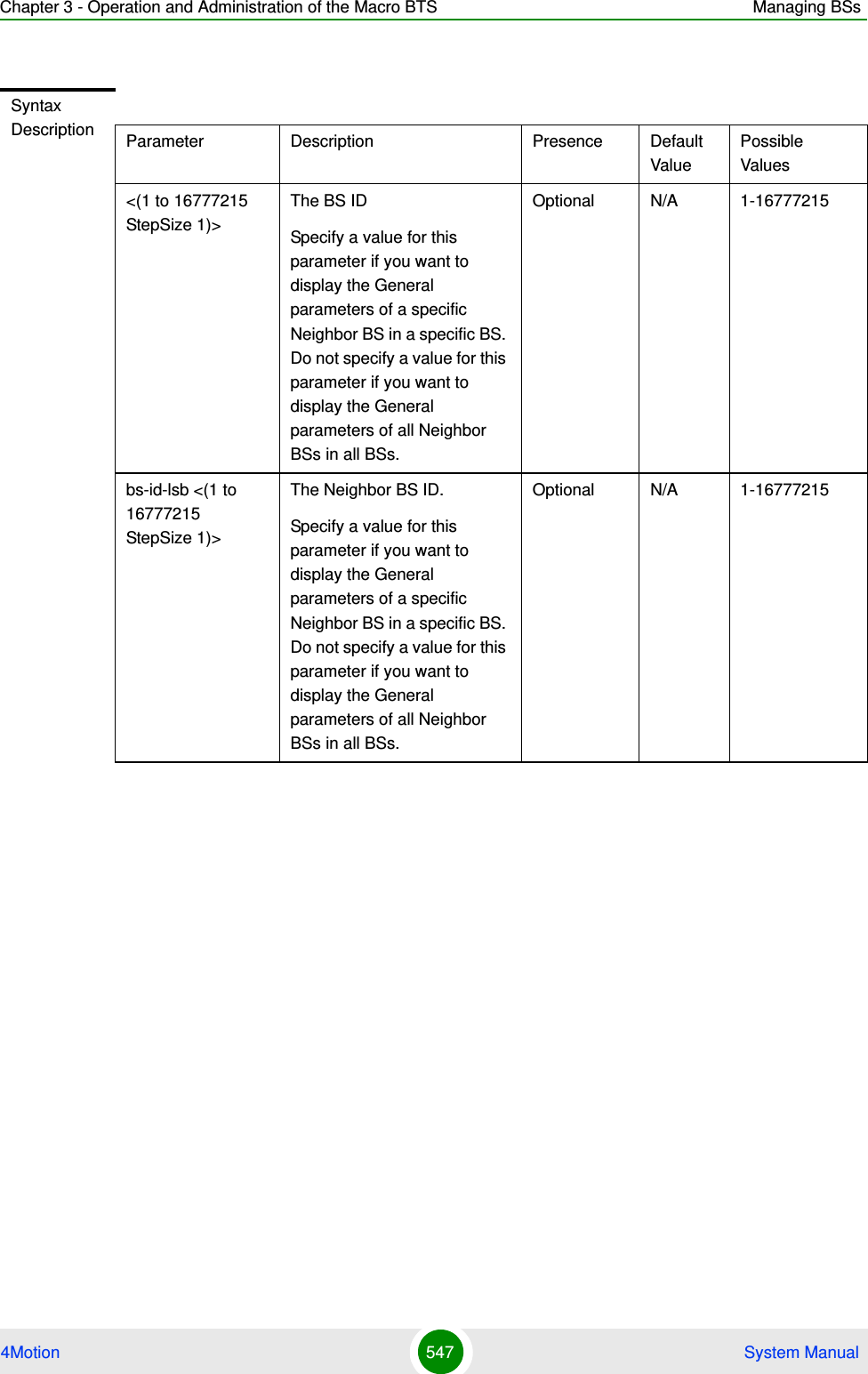
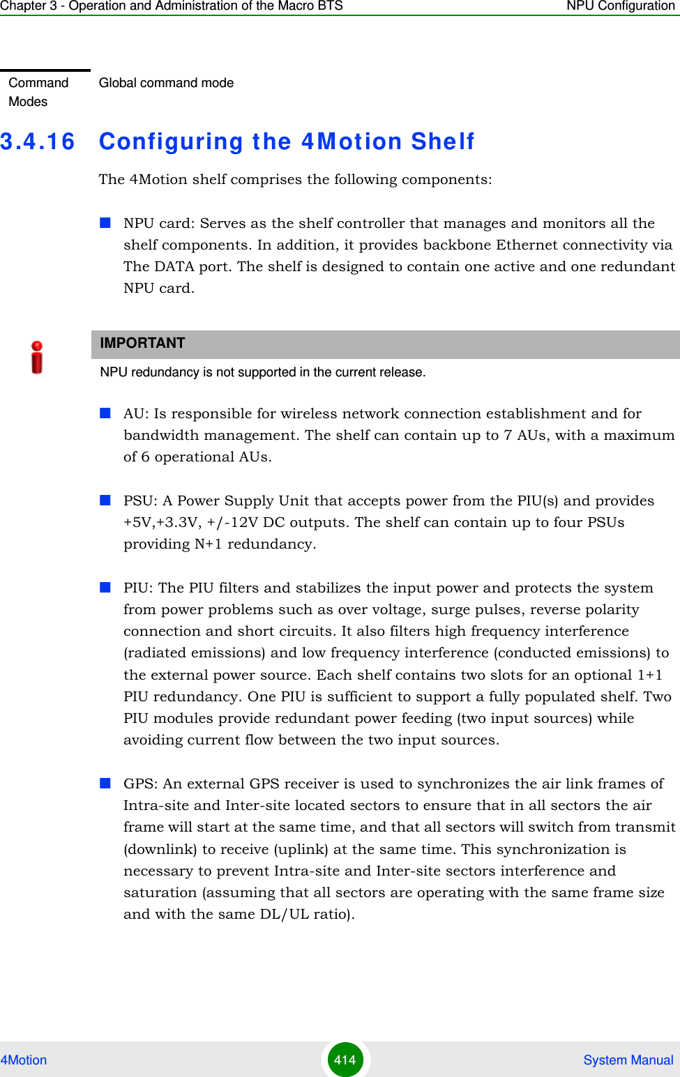
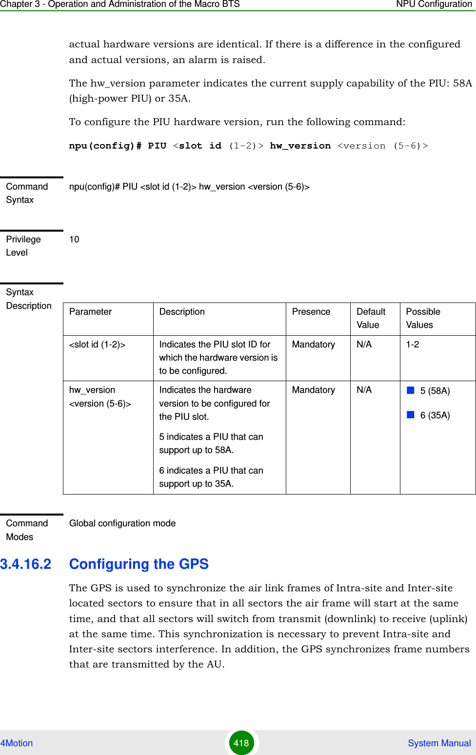
![Chapter 3 - Operation and Administration of the Macro BTS NPU Configuration4Motion 399 System ManualSpecify the module name if you want to configure the severity level separately for this module. If you do not specify the name of the module, the severity level that you configure in this command is applied to all modules. For example, run the following command if you want logs to be created for WiMAX signaling protocols when the severity level is Error or higher:npu(config)# log level SIGASN ERROROr run the following command to set the severity level to Error for all modules:npu(config)# log level ERRORFaultMgr Fault management proceduresShelfMgr Shelf management proceduresSIGASN WiMAX signaling protocolsUserIF User-initiated proceduresAUMgr Internal processes used for managing AUPerfMgr Performance management proceduresNOTEYou can display the currently configured severity levels for each module. For details, refer Section 3.4.13.2.2.Command Syntaxnpu(config)# log level [{StartupMgr|SWDownload|FaultMgr|PerfMgr|ShelfMgr|SIGASN|UserIF|AUMgr}] {ALERT|ERROR|INFO}Privilege Level10Table 3-24: Modules for which Logging can be Enabled](https://usermanual.wiki/Alvarion-Technologies/MICRO-25.Manual-p4/User-Guide-1329245-Page-1.png)
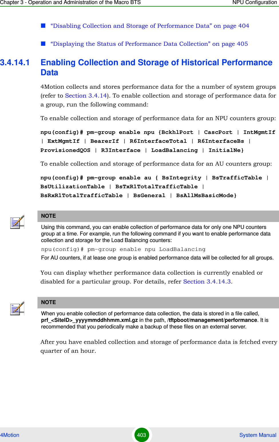
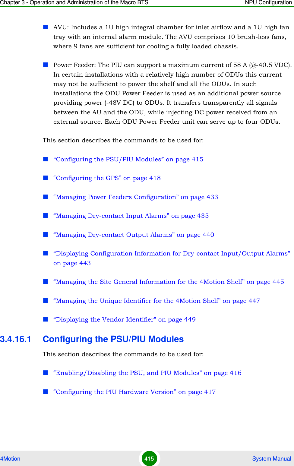
![Chapter 3 - Operation and Administration of the Macro BTS NPU Configuration4Motion 400 System Manual3.4.13.2.2 Displaying Configuration Information for Module-level LoggingTo display the log level configured for one or all modules, run the following command. npu(config)# show log level [{StartupMgr|SWDownload|FaultMgr|PerfMgr|ShelfMgr|SIGASN|UserIF|AUMgr}]Specify the module for which you want to view the configured severity level. If you do not specify the name of the module, the log level configured for all modules is displayed.Syntax Description Parameter Description Presence Default ValuePossible Values[{StartupMgr|SWDownload|FaultMgr|PerfMgr|ShelfMgr|SIGASN|UserIF|AUMgr}]Indicates the name of the module for which the severity level is to be specified.If you do not specify any value for this parameter, the severity level that you specify is applied for all modules. For more information about these parameters, refer Table 3-24.Optional N/A StartupMgrSWDownloadFaultMgrPerfMgrShelfMgrSIGASNUserIFAUMgr{ALERT|ERROR|INFO}Indicates the severity level to be applied to a particular or all modules. Mandatory Error ALERTERRORINFOCommand ModesGlobal configuration modeCommand Syntaxnpu(config)# show log level [{StartupMgr|SWDownload|FaultMgr|PerfMgr|ShelfMgr|SIGASN|UserIF|AUMgr}]](https://usermanual.wiki/Alvarion-Technologies/MICRO-25.Manual-p4/User-Guide-1329245-Page-2.png)
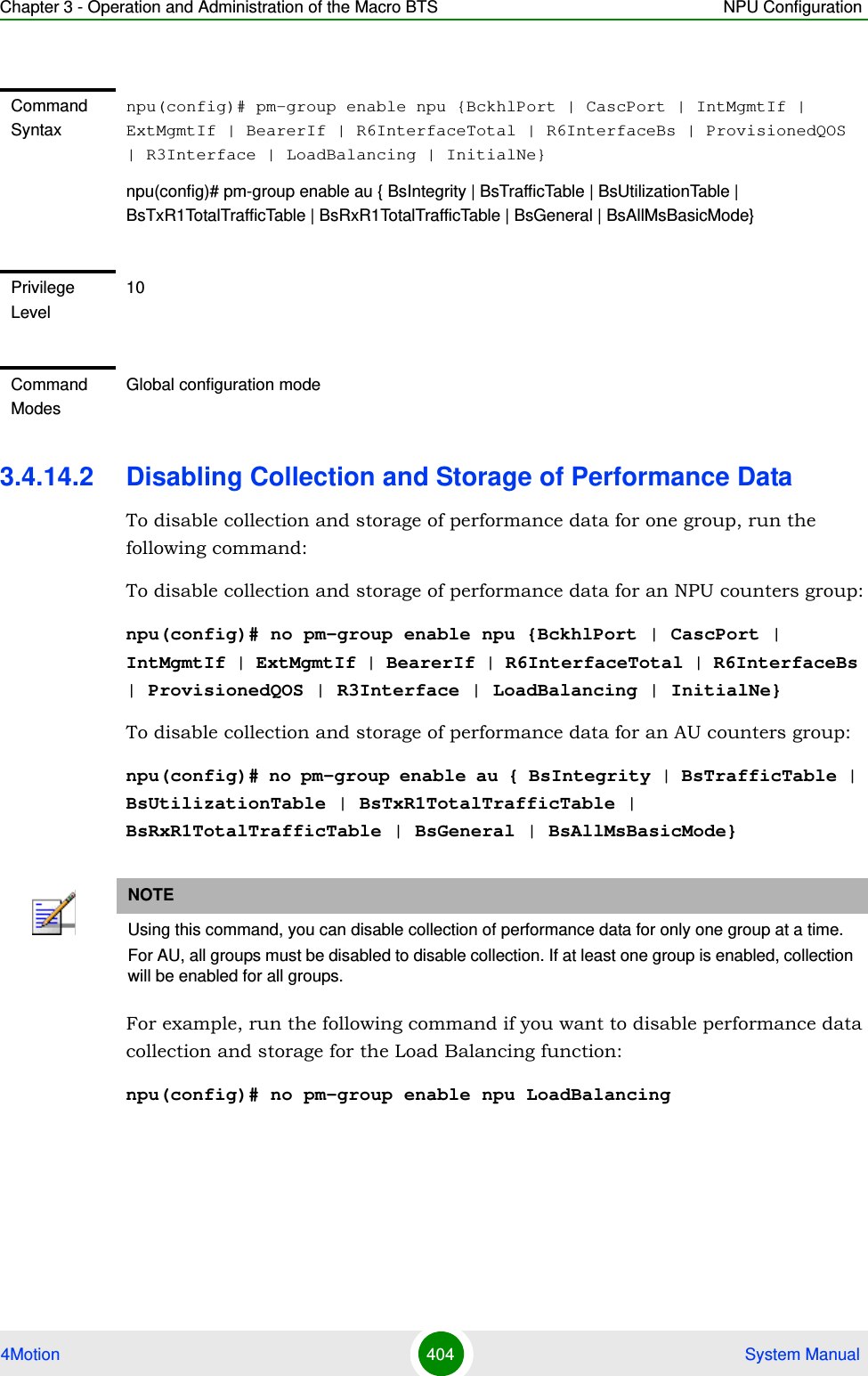
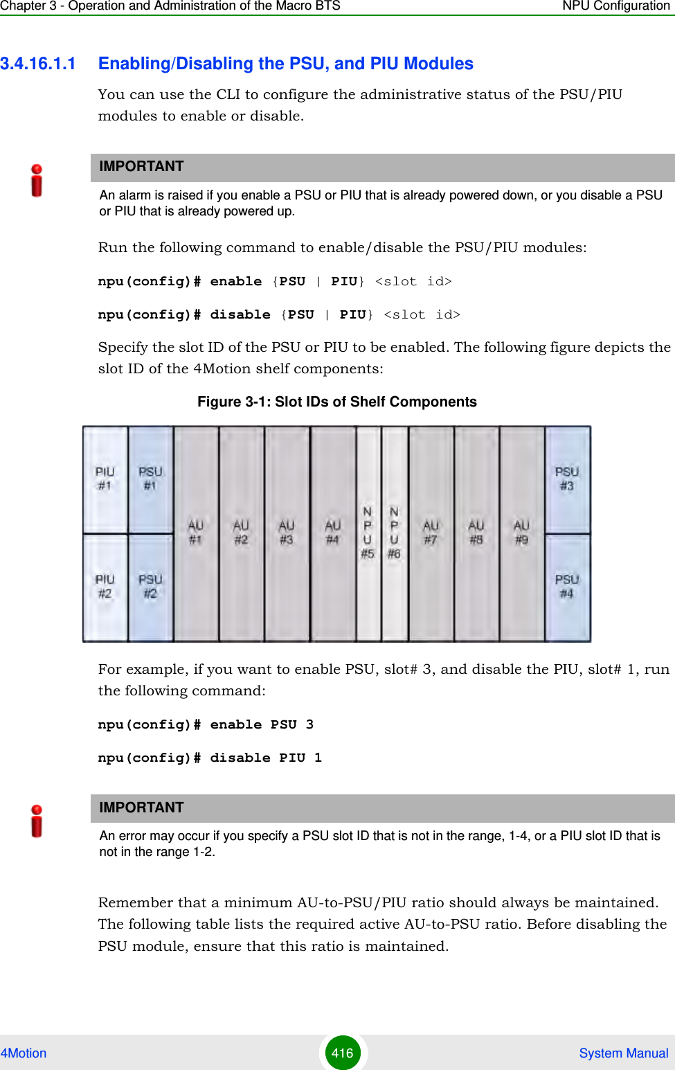
![Chapter 3 - Operation and Administration of the Macro BTS NPU Configuration4Motion 401 System Manual3.4.13.2.3 Disabling Module-level LoggingTo disable logging for one or all system modules, run the following command:npu(config)# no log level [{StartupMgr|SWDownload|FaultMgr|PerfMgr|ShelfMgr|SIGASN|UserIF|AUMgr}]Specify the name of the module if you want to disable logging for a specific module. If you do not specify the module name, logging is disabled for all modules.Privilege Level1Syntax Description Parameter Description Presence Default ValuePossible Values[{StartupMgr|SWDownload|FaultMgr|PerfMgr|ShelfMgr|SIGASN|UserIF|AUMgr}]Indicates the name of the module for which you want to view the configured severity level. For more information about these parameters, refer Table 3-24.If you do not specify any value for this parameter, the severity level is displayed for all modules.Optional N/A StartupMgrSWDownloadFaultMgrPerfMgrShelfMgrSIGASNUserIFAUMgrDisplay FormatModule Name : Log level<Module Name> : <Log Level>Command ModesGlobal configuration modeCommand Syntaxnpu(config)# no log level [{StartupMgr|SWDownload|FaultMgr|PerfMgr|ShelfMgr|SIGASN|UserIF|AUMgr}]](https://usermanual.wiki/Alvarion-Technologies/MICRO-25.Manual-p4/User-Guide-1329245-Page-3.png)
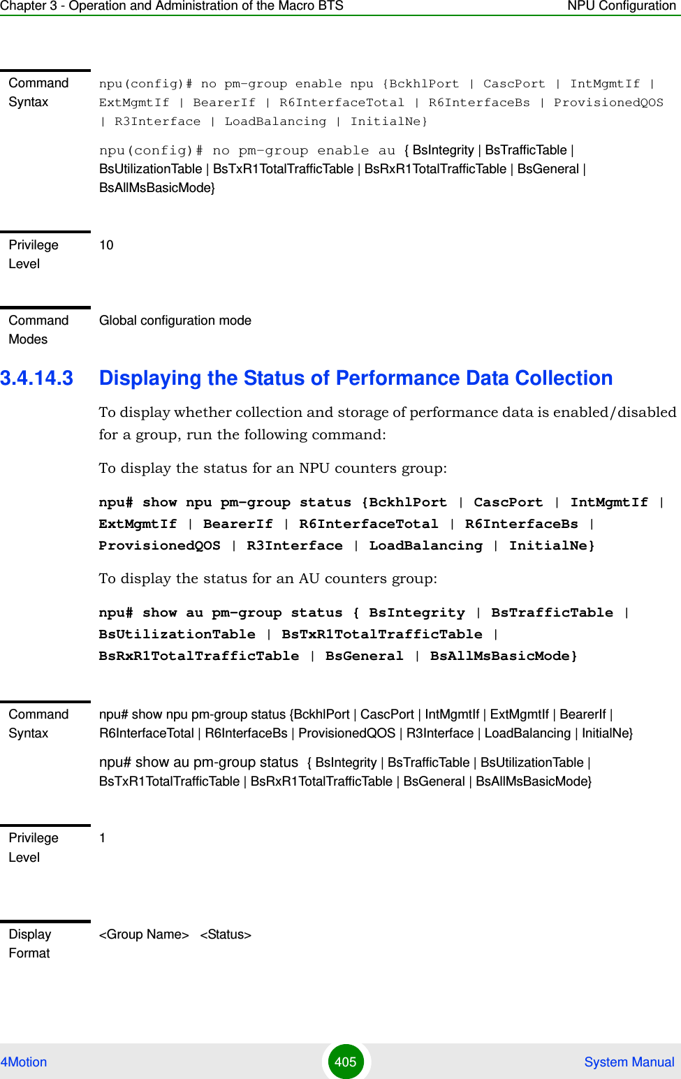
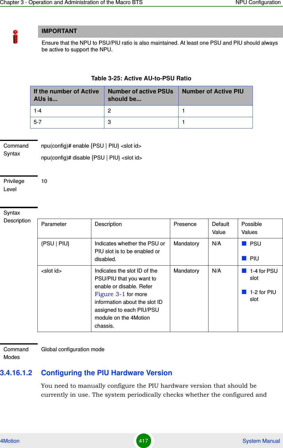
![Chapter 3 - Operation and Administration of the Macro BTS NPU Configuration4Motion 402 System Manual3.4 .14 Configuring Performance Data CollectionYou can configure 4Motion to periodically collect and store performance counters.For details on the counters groups and the performance data counters collected for each group refer to the relevant 4Motion Performance Management document.You can specify the group for which performance data is to be stored and collected.The data is stored in an XML file called, prf_<SiteID>_yyyymmddhhmm.xml.gz in the path,/tftpboot/management/performance. The system maintains this data for a maximum of 24 hours after which it is deleted. It is recommended that you periodically make a backup of these files on an external server.You can enable/disable collection of performance data for each group separately. This section describes:“Enabling Collection and Storage of Historical Performance Data” on page 403Privilege Level10Syntax Description Parameter Description Presence Default ValuePossible Values[{StartupMgr|SWDownload|FaultMgr|PerfMgr|ShelfMgr|SIGASN|UserIF|AUMgr}]Indicates the name of the module for which logging is to be disabled.If you do not specify any value for this parameter, logging is disabled for all parameters. For more information about these modules, refer Table 3-24.Optional N/A StartupMgrSWDownloadFaultMgrPerfMgrShelfMgrSIGASNUserIFAUMgrCommand ModesGlobal configuration mode](https://usermanual.wiki/Alvarion-Technologies/MICRO-25.Manual-p4/User-Guide-1329245-Page-4.png)
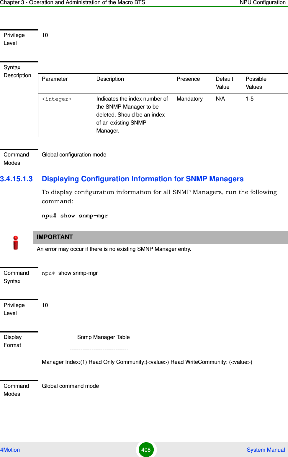
![Chapter 3 - Operation and Administration of the Macro BTS NPU Configuration4Motion 406 System Manual3.4 .15 Configuring the SNMP/Tra p ManagerThis section describes the commands for:“Configuring the SNMP Manager” on page 406“Configuring the Trap Manager” on page 4093.4.15.1 Configuring the SNMP ManagerTo enable 4Motion configuration over SNMP, you are required to first configure the SNMP Manager. You can configure up to five SNMP Manager entries for the 4Motion system, where each entry is uniquely identified by the pair of values for the Read Community and Write Community. This section describes the commands to be executed for:“Adding an SNMP Manager” on page 406“Deleting an Entry for the SNMP Manager” on page 407“Displaying Configuration Information for SNMP Managers” on page 4083.4.15.1.1 Adding an SNMP ManagerYou can configure upto five SNMP Managers. To add an SNMP Manager, run the following command:npu(config)# snmp-mgr [ReadCommunity <string>] [ReadWriteCommunity <string>]You can display configuration information for existing SNMP Managers. For details, refer Section 3.4.15.1.3.Command ModesGlobal command modeNOTEAn existing SNMP Manager entry cannot be modify. To modify the parameters of an SNMP Manager, delete the entry and add a new entry with the required parameters.](https://usermanual.wiki/Alvarion-Technologies/MICRO-25.Manual-p4/User-Guide-1329245-Page-8.png)
![Chapter 3 - Operation and Administration of the Macro BTS NPU Configuration4Motion 407 System Manual3.4.15.1.2 Deleting an Entry for the SNMP ManagerTo delete an SNMP Manager entry, run the following command:npu(config)# no snmp-mgr index <integer>IMPORTANTAn error may occur if you have specified:More than five entries for the SNMP Manager Duplicate entries (an snmp-mgr entry is uniquely identified by values for "ReadCommunity" and "WriteCommunity")Command Syntaxnpu(config)# snmp-mgr [ReadCommunity <string>] [ReadWriteCommunity <string>]Privilege Level10Syntax Description Parameter Description Presence Default ValuePossible Values[ReadCommunity <string>]The SNMP Read Community string allowing execution of SNMP Get operations.Optional public String (up to 10 characters and case-sensitive)[ReadWriteCommunity <string>]The SNMP Read/Write Community string allowing execution of SNMP Set and Get operations.Optional private String (up to 10 characters and case-sensitive)Command ModesGlobal configuration modeIMPORTANTAn error may occur if you provide an incorrect index number for the SNMP Manager to be deleted. To display the index numbers for configured SNMP Managers, refer Section 3.4.15.1.3.Command Syntaxnpu(config)# no snmp-mgr index <integer>](https://usermanual.wiki/Alvarion-Technologies/MICRO-25.Manual-p4/User-Guide-1329245-Page-9.png)
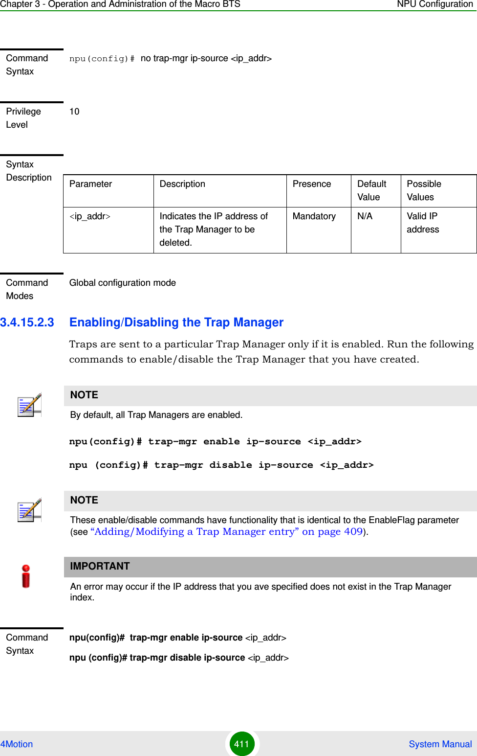
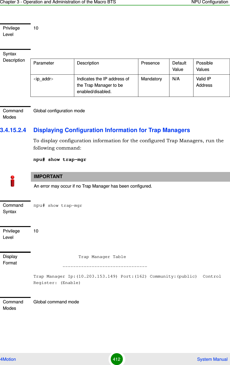
![Chapter 3 - Operation and Administration of the Macro BTS NPU Configuration4Motion 409 System Manual3.4.15.2 Configuring the Trap ManagerThe SNMP Agent can send traps to multiple Trap Managers, for which an entry exists in the 4Motion system. After you have created an entry for a Trap Manager, you are required to enable the Trap Manager. You can, at any time, disable a Trap Manager for the 4Motion system.This section describes the commands for:“Adding/Modifying a Trap Manager entry” on page 409“Deleting an Entry for the Trap Manager” on page 410“Enabling/Disabling the Trap Manager” on page 411“Displaying Configuration Information for Trap Managers” on page 412“Displaying the Trap Rate Limit” on page 4133.4.15.2.1 Adding/Modifying a Trap Manager entryYou can configure up to five Trap Manager entries for the 4Motion system. To add a Trap Manager entry, or to modify an existing entry, run the following command:npu(config)# trap-mgr ip-source <ip_addr> [Port <(0-65535)>] [TrapCommunity <string>] [EnableFlag <integer(1 for enable, 2 for disable)>]You can view configuration information for existing Trap Managers. For details, refer Section 3.4.15.2.4.IMPORTANTAn error may occur if :You have specified invalid values for the IP address, Trap Community or port.The IP address is already configured for another Trap Manager.You are trying to create more than five Trap Managers. (You can configure up to five Trap Managers for the 4Motion system.Command Syntaxnpu(config)# trap-mgr ip-source <ip_addr> [Port <(0-65535)>] [TrapCommunity <string>] [EnableFlag <integer(1 for enable, 2 for disable)>]](https://usermanual.wiki/Alvarion-Technologies/MICRO-25.Manual-p4/User-Guide-1329245-Page-11.png)
![Chapter 3 - Operation and Administration of the Macro BTS NPU Configuration4Motion 410 System Manual3.4.15.2.2 Deleting an Entry for the Trap ManagerTo delete a Trap Manager, run the following command:npu(config)# no trap-mgr ip-source <ip_addr>Privilege Level10Syntax Description Parameter Description Presence Default ValuePossible Values<ip_addr> Indicates the IP address of the Trap Manager to be added or modified.Must be unique (the same IP address cannot be assigned to more than one Manager)Mandatory N/A Valid IP address[Port <(0-65535)>]Indicates the port number on which the Trap Manager will listen for messages from the Agent.Optional 162 0-65535[TrapCommunity <string>] Indicates the name of the community of the Trap Manager. Optional public String (up to 10 characters and case-sensitive)[EnableFlag<integer(1 for enable, 2 for disable)>] Indicates whether traps sending to the Trap Manager is to be enabled. or disabledOptional 1 1: Indicates enable2 Indicates disableCommand ModesGlobal configuration modeIMPORTANTA route to forward traps to a configured Trap Manager IP address must exist. For details refer to “Configuring Static Routes” on page 192..IMPORTANTAn error may occur if the IP address you have specified does not exist.](https://usermanual.wiki/Alvarion-Technologies/MICRO-25.Manual-p4/User-Guide-1329245-Page-12.png)
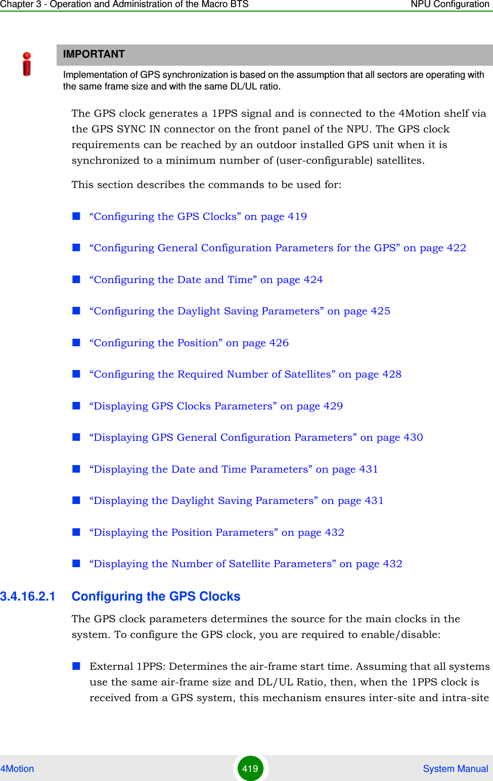
![Chapter 3 - Operation and Administration of the Macro BTS NPU Configuration4Motion 420 System Manualsynchronization among all sectors, preventing cross interference and saturation problems. When using the internal 1PPS clock (derived from the selected 16 MHz clock source), only intra-site synchronization among sectors can be achieved. You can either enable the external 1PPS clock source or use the internal 1PPS clock source derived from the selected 16 MHz clock. By default, the External IPPS clock is enabled. When using a GPS for synchronization, the 1PPS clock is received from the GPS receiver and must be enabled for proper operation.External 16MHz: Generates all the main clocking signals in the system, including the internal 1PPS clock. Using an external, accurate 16 MHz clock source will enable better hold-over of the 1PPS clock upon temporary loss (or reduced reliability when receiving less than 4 satellites) of the external 1PPS clock. This will allow a longer time of continued operation before appearance of interferences due to clock drifts among BSs. You can either enable the external 16 MHz clock source or use the internal 16 MHz clock source. By default, the external 16MHz clock is disabled. In the current release external 16MHz clock must be disabled.To configure the GPS clock, run the following command:npu(config)# set clock ([ External1PPS {Enable | Disable} ] [ External16MHz {Enable | Disable} ])For example, to configure the internal 1PPS clock at the NPU to synchronize the air frames for inter-site and intra-site sectors:npu(config)# set clock External1PPS DisableNOTEIf the external 1PPS GPS clock is enabled:The concatenated slave NPU 16Mhz created from local 16MHz TCXO/OCXO at the NPU provides holdover when the GPS loses synchronization with its satellites.Configure the GPS parameters listed in section, Section 3.4.16.2.2.IMPORTANTReset the system for changes in the GPS clock configuration to be applied to the entire system.Command Syntaxnpu(config)# set clock ([External1PPS {Enable | Disable}] [External16MHz {Enable | Disable}])](https://usermanual.wiki/Alvarion-Technologies/MICRO-25.Manual-p4/User-Guide-1329245-Page-22.png)
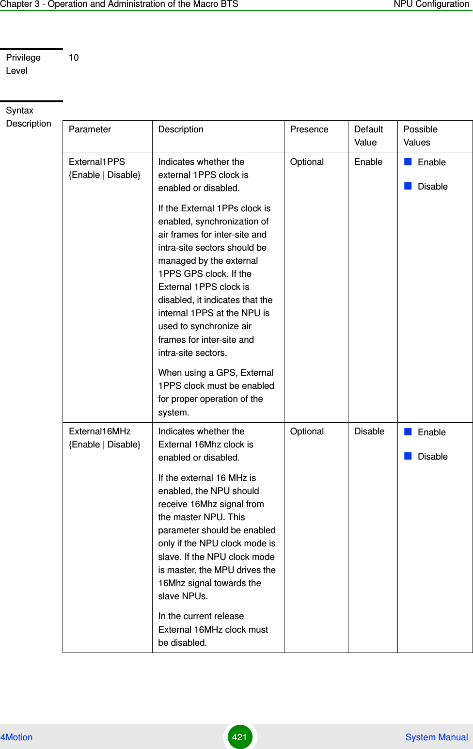
![Chapter 3 - Operation and Administration of the Macro BTS NPU Configuration4Motion 422 System Manual3.4.16.2.2 Configuring General Configuration Parameters for the GPSThe GPS general configuration parameters determine how the GPS should function with respect to the 4Motion system. Depending upon the values defined for these parameters, you can configure the GPS clock (external 1PPS and 16MHz), and the UTC time. Run the following command to configure the global configuration parameters for the GPS:npu(config)# gps config ( [Type {Trimble | Lassen | None}][HoldoverPassedTout <expiry_interval(0-2880)>] [HoldoverPassTxOperationStop {Enable | Disable}][AlmanacUsableTime <expiry_interval(0-4320)>] [EphemerisUsableTime <expiry_interval(0-168)>] [IntervalToReadGPSTime{Hourly | Daily | Monthly | Yearly}] [TimeToReadGPSTime <HH:MM:SS,DD/MM>]))Command ModesGlobal configuration modeIMPORTANTSkip this section if you have selected the internal 1PPS clock. For more information about configuring the GPS clock, refer Section 3.4.16.2.1.IMPORTANTAn error may occur if:Time to read GPS time is not in valid format. Correct format is hh:mm:ss, dd/mm: Minute and Second should be within range of 0 to 60, Hour should be within the range of 0 to 23, days should be in the range 1 to 31 and Month should be within the range of 1 to 12, also day should be valid in accordance with month.Command Syntaxnpu(config)# gps config ( [Type {Trimble | Lassen| None}] [HoldoverPassedTout <expiry_interval(0-2880)>] [HoldoverPassTxOperationStop {Enable | Disable}][AlmanacUsableTime <expiry_interval(0-4320)>] [EphemerisUsableTime <expiry_interval(0-168)>] [IntervalToReadGPSTime{Hourly | Daily | Monthly | Yearly}] [TimeToReadGPSTime <HH:MM:SS,DD/MM>]))Privilege Level10](https://usermanual.wiki/Alvarion-Technologies/MICRO-25.Manual-p4/User-Guide-1329245-Page-24.png)
![Chapter 3 - Operation and Administration of the Macro BTS NPU Configuration4Motion 423 System ManualSyntax DescriptionParameter Description Presence Default ValuePossible ValuesType {Trimble | Lassen | None}]Indicates the type of GPS connected to 4Motion:Trimble: Use for BMAX-Timing GPS-OGR model.Lassen: Use for BMAX-4M-GPS modelNone: Use when no GPS is connected.Optional Trimble TrimbleLassenNone[HoldoverTimeout <expiry_interval (0-2880)>]Indicates the period, in minutes, for which the NPU provides holdover when the GPS loses synchronization with its satellites. Optional 480 0 - 2880[HoldoverPassTxOperationStop{Enable | Disable}]Indicates whether the AU modules should stop data transmission if the GPS loses synchronization with its satellites and the holdover timeout has occurred.Optional Enable EnableDisable[AlmanacUsableTime <expiry-interval(0-4320)>]Indicates the maximum period, in hours, for which the Almanac time is valid when the GPS is reset.Optional 720 0-4320[EphemerisUsableTime <expiry-interval(0-168)>]Indicates the maximum period, in hours, for which the Ephemeris time is valid when the GPS is reset.Optional 4 0-168[IntervalToReadGPSTime {Hourly | Daily | Monthly | Yearly}]Indicates the interval after which the NPU should obtain the GPS time for frame synchronization, and send it to the AU.Optional Daily HourlyDailyMonthlyYearly](https://usermanual.wiki/Alvarion-Technologies/MICRO-25.Manual-p4/User-Guide-1329245-Page-25.png)
![Chapter 3 - Operation and Administration of the Macro BTS NPU Configuration4Motion 424 System Manual3.4.16.2.3 Configuring the Date and TimeThe UTC time is used to configure the following:Local time: Differs from the UTC time with respect to the value you have specified for the localUTCDiff and DST parameters. The local time is equal to the sum of the UTC time, the value of the localUTCDiff parameter (local offset from UTC time) and DST (daylight saving time offset). For more information about configuring this parameter, “Configuring the GPS Clocks” on page 419. You can use the CLI to display the current local time. For details, refer the section, “Displaying the Date and Time Parameters” on page 431.System time: Refers to the operating system (kernel) time that is identical to the UTC time when the system boots up. The system time is updated every hour with the time received from the GPS receiver.Real Time Clock (RTC) time: Refers to the time maintained by the board’s hardware clock. By default, the RTC time is set to 1st January, 1970. The RTC time is updated every hour with the UTC time that is received from the GPS receiver or that you have configured from the CLI. The RTC time is used for creating the timestamp for log and trace messages, performance data collection files, and for managing the interval after which a backup of the configuration file should be maintained and performance data should be collected.Execute the following command to configure the date and time parameters. If the GPS is synchronized to its satellites and is connected to 4Motion, the UTC time is provided by the GPS. Otherwise the UTC time that you configure is used instead.To configure the date and time parameters, run the following command:npu(config)# set date [UTC <HH:MM:SS,DD/MM/YYYY>] [LocalUTCDiff <+/-HH:MM>] [DST <(0-2)>][TimeToReadGPSTime <HH:MM:SS,DD/MM>]Indicates the time when the NPU should obtain the GPS time for frame synchronization..Optional 04:05 HH:MM:SS,DD/MMCommand ModesGlobal configuration mode](https://usermanual.wiki/Alvarion-Technologies/MICRO-25.Manual-p4/User-Guide-1329245-Page-26.png)
![Chapter 3 - Operation and Administration of the Macro BTS NPU Configuration4Motion 425 System Manual3.4.16.2.4 Configuring the Daylight Saving ParametersTo configure the daylight saving parameters, run the following command:npu(config)# set daylight saving ([mode {Enable | Disable}] [start-date <DD.MM>] [stop-date <DD.MM>])IMPORTANTAn error may occur if :1) UTC time is not in the valid format i.e. hh: mm: ss, dd/mm/yyyy. 2) Local UTCDiff is not valid format i.e. +/-hh:mm3) Local UTC Diff is out of the range between -12 to +13 or it is not in steps of 30 minutes.4) DST is out of range i.e between 0 to 2 Command Syntaxnpu(config)# set date [UTC <HH:MM:SS,DD/MM/YYYY>] [LocalUTCDiff <+/-HH:MM>] [DST <(0-2)>]Privilege Level10Syntax Description Parameter Description Presence Default ValuePossible ValuesUTC <HH:MM:SS,DD/MM/YYYY>Indicates the UTC time to be used for 4Motion if not available from GPS.Optional N/A Use the format:HH:MM: SS, DD/MM/YYYYLocalUTCDiff <+/-HH:MM>The local offset from UTC Optional +00:00 +/-HH:MMHH: -12 to +13MM: 00 or 30DST <(0-2)> Applicable only of daylightSavingMode is set to Enable. Daylight Saving Time offset of the local clockOptional 0 0-2Command ModesGlobal configuration modeIMPORTANTAn error may occur if any of the configured value is not in a valid format:](https://usermanual.wiki/Alvarion-Technologies/MICRO-25.Manual-p4/User-Guide-1329245-Page-27.png)
![Chapter 3 - Operation and Administration of the Macro BTS NPU Configuration4Motion 426 System Manual3.4.16.2.5 Configuring the PositionThe position configuration enables setting the location’s parameters when GPS is not used (Type=None).To configure the position parameters, run the following command:Command Syntaxnpu(config)# set daylight saving ([mode {Enable | Disable}] [start-date <DD.MM>] [stop-date <DD.MM>])Privilege Level10Syntax Description Parameter Description Presence Default ValuePossible Valuesmode {Enable | Disable}Enables/disables the daylight saving feature. When enabled, the feature will be activated using the parameters defined below.Optional Disable EnableDisablestart-date <DD.MM>Applicable only of Mode is set to Enable. The date for starting the daylight saving feature: At the beginning of this date (midnight), the clock will be advanced by the amount of hours specified by the Advance Factor parameter.Optional 27.3 DD.MMDD: .day in month, 1-31.MM .month in year, 1-12.stop-date <DD.MM>Applicable only of Mode is set to Enable. The date for stopping the daylight saving feature: At the end of this date (midnight plus the amount of hours specified by the Advance Factor parameter), the clock will be set back to midnight (00:00).Optional 28.11 DD.MMDD: .day in month, 1-31.MM .month in year, 1-12.Command ModesGlobal configuration mode](https://usermanual.wiki/Alvarion-Technologies/MICRO-25.Manual-p4/User-Guide-1329245-Page-28.png)
![Chapter 3 - Operation and Administration of the Macro BTS NPU Configuration4Motion 427 System Manualnpu(config)# set position ([Latitude <xx.xxx,N/S>] [Longitude <xxx.xxx,E/W>] [Altitude (-300 - 9000)])IMPORTANTAn error may occur if :1) Latitude, longitude and altitude are configured while GPS type is not "None".2) Latitude is not in valid format i.e. ll.mmm,a where a is either N or S3) Longitude is not in valid format i.e. lll.mmm,a where a is either E or W.4) Altitude is not in valid range i.e. +-300 to 9000.Command Syntaxnpu(config)# set position ([Latitude <xx.xxx,N/S>] [Longitude <xxx.xxx,E/W>] [Altitude (-300 - 9000)])Privilege Level10Syntax Description Parameter Description Presence Default ValuePossible ValuesLatitude <xx.xxx,N/S>Indicates the latitude where the 4Motion shelf is currently positioned. Configure only if GPS Type is None.Optional 00.000,N Use the format, ll.mmm.a (where ll.mmm is in degrees and the value of a is either N or S).ll is between 00 to 89, mmm is between 000 to 999.](https://usermanual.wiki/Alvarion-Technologies/MICRO-25.Manual-p4/User-Guide-1329245-Page-29.png)
![Chapter 3 - Operation and Administration of the Macro BTS NPU Configuration4Motion 428 System Manual3.4.16.2.6 Configuring the Required Number of SatellitesThe satellite parameter enables configured the minimum number of satellites required for maintaining synchronization and for renewing synchronization after synchronization loss.To configure the satellite parameters, run the following command:npu(config)# set satellite ([MinNumOfSatForHoldoverReturn <range (1-12)>] [MaxNumOfSatBeforeSyncLoss <range (0-11)>])Longitude <xxx.xxx,E/W>Indicates the longitude where the 4Motion shelf is currently positioned. Configure only if GPS Type is None.Optional 000.000,E Use the format, Ill.mmm.a (where ll.mmm is in degrees and the value of a is either E or W).lll is between 000 to 179, mmm is between 000 to 999.Altitude (-300 - 9000)])Indicates the altitude (in meters) where the 4Motion shelf is currently positioned. Configure only if GPS Type is None.Optional 0 -300 to 9000Command ModesGlobal configuration modeIMPORTANT1) An error can occur while configuring MinNumOfSatForHoldoverReturn if Minimum number of satellite for holdover return is less than Maximum number of satellite before synchronization loss.2) An error can occur while configuring MaxNumOfSatBeforeSyncLoss if Maximum number of satellite before synchronization is more than Minimum number of satellite for holdover return.Command Syntaxnpu(config)# set satellite ([MinNumOfSatForHoldoverReturn <range (1-12)>] [MaxNumOfSatBeforeSyncLoss <range (0-11)>]Privilege Level10](https://usermanual.wiki/Alvarion-Technologies/MICRO-25.Manual-p4/User-Guide-1329245-Page-30.png)
![Chapter 3 - Operation and Administration of the Macro BTS NPU Configuration4Motion 429 System Manual3.4.16.2.7 Displaying GPS Clocks ParametersTo display the GPS clock configuration parameters, run the following command:npu# show clock status [{CurrentExternal1PPS | ConfiguredExternal1PPS | CurrentExtrnal16MHz | ConfiguredExternal16MHz}]Syntax Description Parameter Description Presence Default ValuePossible ValuesMinNumOfSatForHoldoverReturn <range (1-12)>Indicates the minimum number of satellites that should be received for resuming synchronization (exiting holdover status) after loss of synchronization.Optional 2 1-12MaxNumOfSatBeforeSyncLoss <range (0-11)>Indicates the minimum number of satellites required for maintaining synchronization.Optional 1 0-11Command ModesGlobal configuration modeCommand Syntaxnpu# show clock status [{CurrentExternal1PPS | ConfiguredExternal1PPS | CurrentExtrnal16MHz | ConfiguredExternal16MHz}Privilege Level1Syntax DescriptionFor a detailed description of each parameter in this command, refer the section, “Configuring the GPS Clocks” on page 419.Both Current and Configured values for each clock are provided (the parameters are applied after reset)](https://usermanual.wiki/Alvarion-Technologies/MICRO-25.Manual-p4/User-Guide-1329245-Page-31.png)
![Chapter 3 - Operation and Administration of the Macro BTS NPU Configuration4Motion 430 System Manual3.4.16.2.8 Displaying GPS General Configuration ParametersTo display the GPS general configuration parameters, run the following command:npu# show gps config [{ Type | SoftwareVersion [{ Navigation | Signal }] | HoldoverPassedTout | HoldoverPassTxOperationStop | AlmanacUsableTime | EphemerisUsableTime | IntervalToReadGPSTime | TimeToReadGPSTime} ]Display FormatConfigured External 1PPS Status :Enable/ DisableCurrent External 1PPS Status :Enable/ DisableConfigured External 16MHz Status :Enable/ DisableCurrent External 16MHz Status :Enable/ DisableCommand ModesGlobal command modeCommand Syntaxnpu# show gps config [{ Type | SoftwareVersion [{ Navigation | Signal }] | HoldoverPassedTout | HoldoverPassTxOperationStop | AlmanacUsableTime | EphemerisUsableTime | IntervalToReadGPSTime | TimeToReadGPSTime} ]Privilege Level1Syntax DescriptionFor a detailed description of each parameter in this command, refer the section, “Configuring General Configuration Parameters for the GPS” on page 422.Display FormatConfigured GPS Type :GPS Navigation Processor SW Version :GPS Signal Processor SW version :Holdover Timeout :HoldoverPassedTxOperationStop :Almanac Usable Time :Ephemeris Usable Time :Interval To Read Gps Time :Time To Read Gps Time :](https://usermanual.wiki/Alvarion-Technologies/MICRO-25.Manual-p4/User-Guide-1329245-Page-32.png)
![Chapter 3 - Operation and Administration of the Macro BTS NPU Configuration4Motion 431 System ManualIn addition to the configuration parameters, the SW Versions of the GPS Navigation and Signal Processors are also displayed (if available).3.4.16.2.9 Displaying the Date and Time ParametersTo display the current date parameters, run the following command:npu# show date [{Local | UTC | LocalUTCDiff | DST}]In addition to the configurable parameters, the calculated Local Time is also displayed.3.4.16.2.10 Displaying the Daylight Saving ParametersTo display the current daylight saving parameters, run the following command:npu# show daylight savingCommand ModesGlobal command modeCommand Syntaxnpu# show date [{Local | UTC | LocalUTCDiff | DST}]Privilege Level1Syntax DescriptionFor a detailed description of each parameter in this command, refer the section, “Configuring the Date and Time” on page 424.Display FormatLocal Time :UTC Time :Local UTC Offset :Daylight Saving Time :Command ModesGlobal command modeCommand Syntaxnpu# show daylight saving](https://usermanual.wiki/Alvarion-Technologies/MICRO-25.Manual-p4/User-Guide-1329245-Page-33.png)
![Chapter 3 - Operation and Administration of the Macro BTS NPU Configuration4Motion 432 System Manual3.4.16.2.11 Displaying the Position ParametersTo display the current position parameters, run the following command:npu# show position [{Latitude | Longitude | Altitude}]3.4.16.2.12 Displaying the Number of Satellite ParametersTo display the current satellite parameters, run the following command:Privilege Level1Display FormatSaving mode :<enabled/disabled>Start date :<value or not configured>Stop date :<value or not configured>Command ModesGlobal command modeCommand Syntaxnpu# show position [{Latitude | Longitude | Altitude}]Privilege Level1Syntax DescriptionFor a detailed description of each parameter in this command, refer the section, “Configuring the Position” on page 426.Display FormatLatitude :Longitude :Altitude :Command ModesGlobal command mode](https://usermanual.wiki/Alvarion-Technologies/MICRO-25.Manual-p4/User-Guide-1329245-Page-34.png)
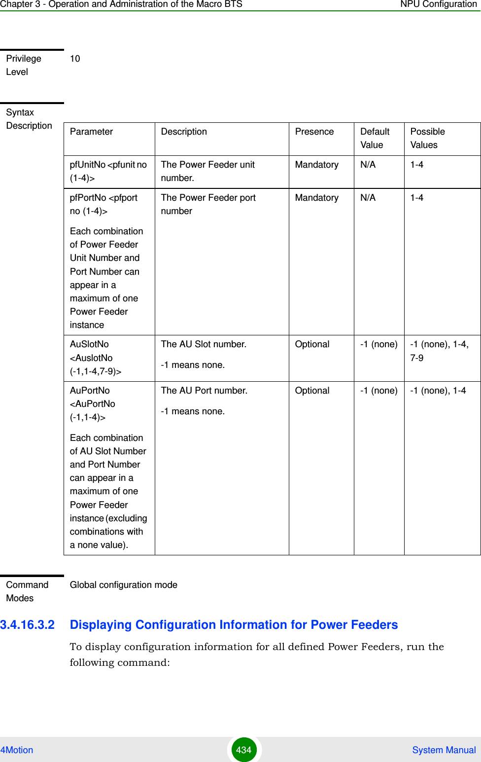
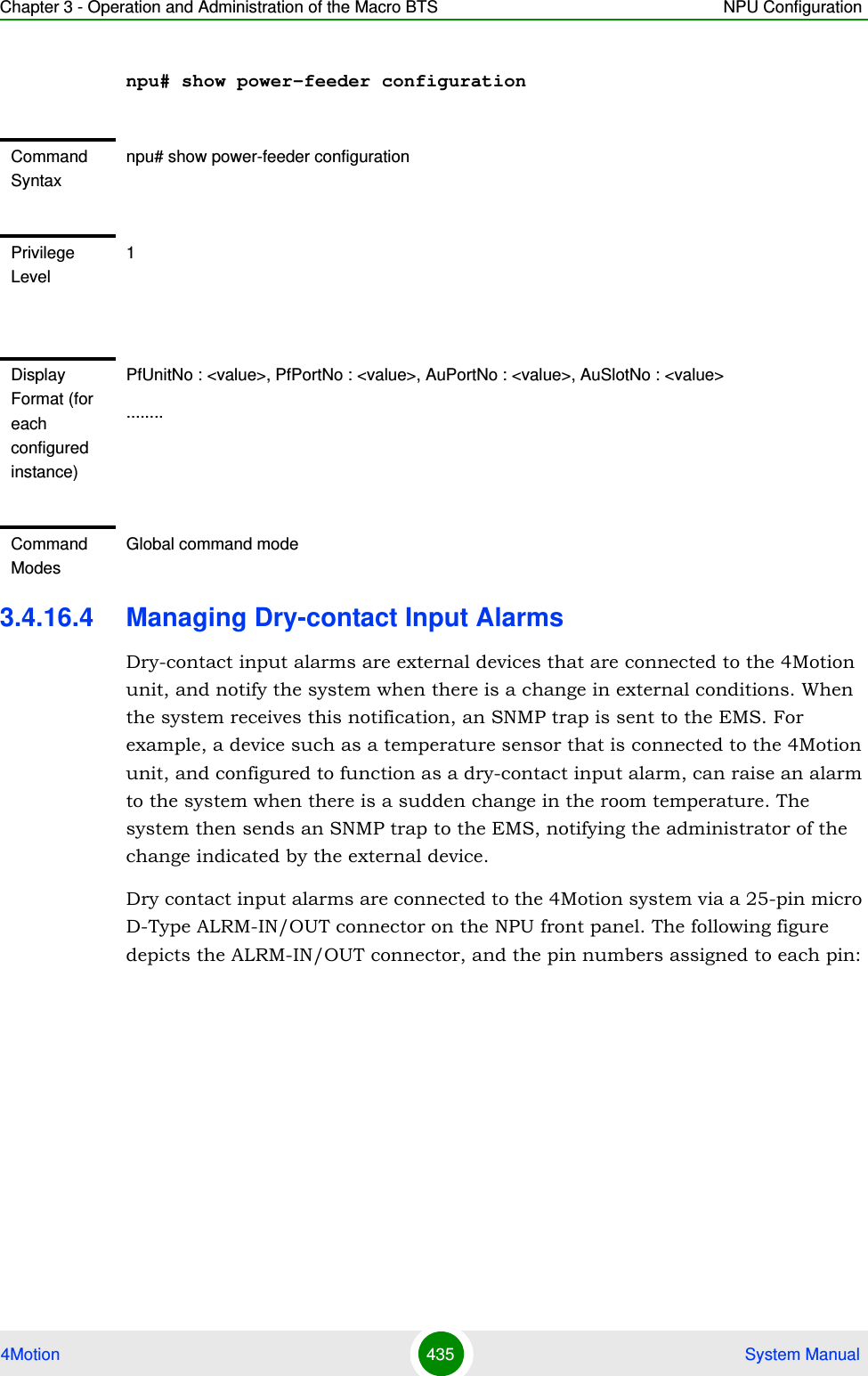
![Chapter 3 - Operation and Administration of the Macro BTS NPU Configuration4Motion 433 System Manualnpu# show satellite [{MinNumOfSatForHoldoverReturn | MaxNumOfSatBeforeSyncLoss | NumOfSatelliteAvailable}]In addition to the configurable parameters, the current number of satellites acquired by the GPS receiver is also displayed.3.4.16.3 Managing Power Feeders ConfigurationThe Power Feeder configuration enables specifying the AU port connected to each Power Feeder port.3.4.16.3.1 Configuring Power FeedersTo configure the AU ports connected to the ports of a specific Power Feeder, run the following command:npu(config)# config pfUnitNo <pfunit no (1-4)> pfPortNo <pfport no (1-4)> AuSlotNo <AuslotNo (-1,1-4,7-9)> AuPortNo <AuPortNo (-1,1-4)>Command Syntaxnpu# show satellite [{MinNumOfSatForHoldoverReturn | MaxNumOfSatBeforeSyncLoss | NumOfSatelliteAvailable}]Privilege Level1Syntax DescriptionFor a detailed description of each parameter in this command, refer the section, “Configuring the Required Number of Satellites” on page 428.Display FormatMax Satellites Before Sync Loss :Min Satellites For Holdover Return :Number of Satellites Acquired :Command ModesGlobal command modeIMPORTANTAn error can occur if the configured combination of AuPortNo and AuSlotNo already exists.Command Syntaxnpu(config)# config pfUnitNo <pfunit no (1-4)> pfPortNo <pfport no (1-4)> AuSlotNo <AuslotNo (-1,1-4,7-9)> AuPort <AuPortNo (-1,1-4)>](https://usermanual.wiki/Alvarion-Technologies/MICRO-25.Manual-p4/User-Guide-1329245-Page-35.png)
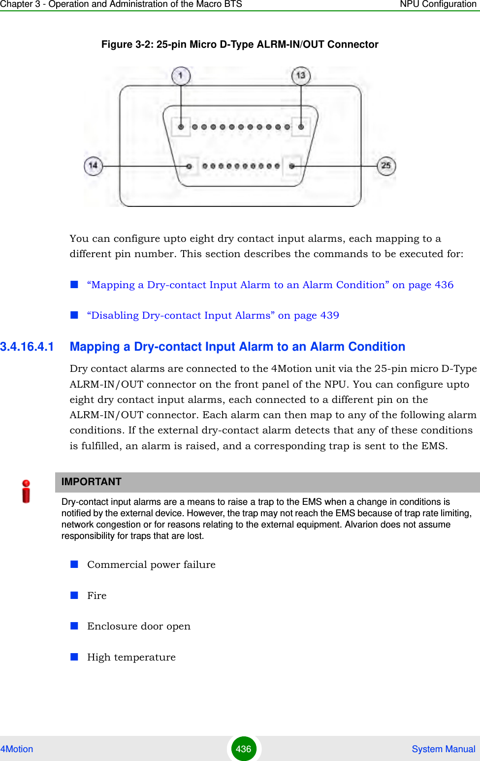
![Chapter 3 - Operation and Administration of the Macro BTS NPU Configuration4Motion 437 System ManualFloodLow fuelLow battery thresholdGenerator failureIntrusion detectionExternal equipment failureTo map the a dry contact alarm to an alarm condition, run the following command:npu(config)# dry-contact IN <alarm_num (1-8)> alarm {CommercialPowerFailure | Fire | EnclosueDoorOpen | HighTemperature | Flood | LowFuel | LowBatteryThreshold | GeneratorFailure | IntrusionDetection | ExternalEquipmentFailure} [alarmPolarity {RaiseOnClose | RaiseOnOpen }] In this command, the alarm_num parameter maps to a pin on the ALRM IN-OUT connector. The following table lists the pin numbers of the 25-pin micro D-Type ALRM-IN/OUT connector corresponding to the alarm number you are configuring:Refer Figure 3-2 for a diagrammatic representation of the 25-pin micro D-Type ALRM-IN/OUT connector and the numbers assigned to each pin.Table 3-26: Pin Numbers Corresponding to Dry Contact Input Alarm NumbersPin Number Alarm Number3 and 15 14 and 16 25 and 17 36 and 18 47 and 19 58 and 20 69 and 21 710 and 22 8](https://usermanual.wiki/Alvarion-Technologies/MICRO-25.Manual-p4/User-Guide-1329245-Page-39.png)
![Chapter 3 - Operation and Administration of the Macro BTS NPU Configuration4Motion 438 System ManualNOTEFor more information about displaying the alarm conditions currently mapped to the micro D-Type ALRM-IN/OUT connector pins, refer Section 3.4.16.6.Command Syntaxnpu(config)# dry-contact IN <alarm_num (1-8)> alarm {CommercialPowerFailure | Fire | EnclosueDoorOpen | HighTemperature | Flood | LowFuel | LowBatteryThreshold | GeneratorFailure | IntrusionDetection | ExternalEquipmentFailure} [alarmPolarity {RaiseOnClose | RaiseOnOpen }]Privilege Level10Syntax Description Parameter Description Presence Default ValuePossible Values<alarm_num (1-8)>Indicates the alarm number of the dry contact input alarm that is to be mapped to an alarm condition. This alarm number corresponds to a pin on the 25-pin micro D-Type jack. For more information about the pin numbers that correspond to the alarm number, refer Table 3-26.Mandatory N/A 1-8](https://usermanual.wiki/Alvarion-Technologies/MICRO-25.Manual-p4/User-Guide-1329245-Page-40.png)
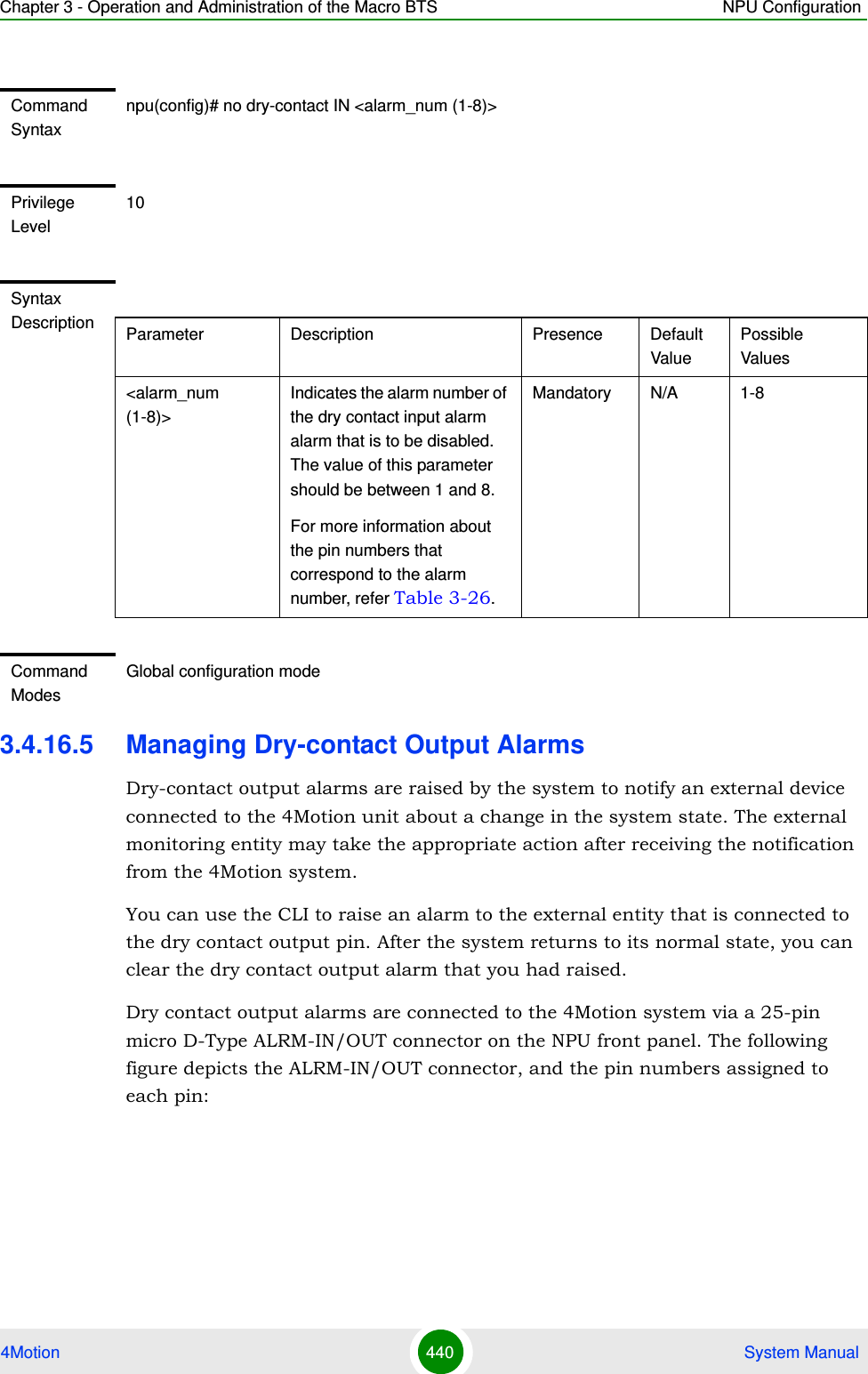
![Chapter 3 - Operation and Administration of the Macro BTS NPU Configuration4Motion 439 System Manual3.4.16.4.2 Disabling Dry-contact Input AlarmsTo disable (block) a dry contact input alarm mapped to a specific alarm condition, run the following command:npu(config)# no dry-contact IN <alarm_num (1-8)>alarm {CommercialPowerFailure | Fire | EnclosueDoorOpen | HighTemperature | Flood | LowFuel | LowBatteryThreshold | GeneratorFailure | IntrusionDetection | ExternalEquipmentFailureIndicates the alarm condition to be mapped to a pin number. Mandatory N/A CommercialPowerFailure FireEnclosueDoorOpenHighTemperatureFloodLowFuelLowBatteryThresholdGeneratorFailureIntrusionDetection ExternalExternalEquipmentFailure (can be used for defining a condition other than the ones specified by the other parameters in this command)[alarmPolarity {RaiseOnClose | RaiseOnOpen }]Indicates whether alarm will be raised on closed or open circuit condition.Optional RaiseOnCloseRaiseOnCloseRaiseOnOpenCommand ModesGlobal configuration modeNOTEFor more information about mapping dry contact alarms to an alarm condition, refer to “Mapping a Dry-contact Input Alarm to an Alarm Condition” on page 436. For more information about displaying the alarm condition currently mapped to an alarm, refer to “Displaying Configuration Information for Dry-contact Input/Output Alarms” on page 443.](https://usermanual.wiki/Alvarion-Technologies/MICRO-25.Manual-p4/User-Guide-1329245-Page-41.png)
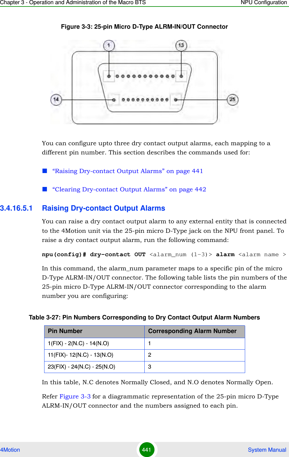
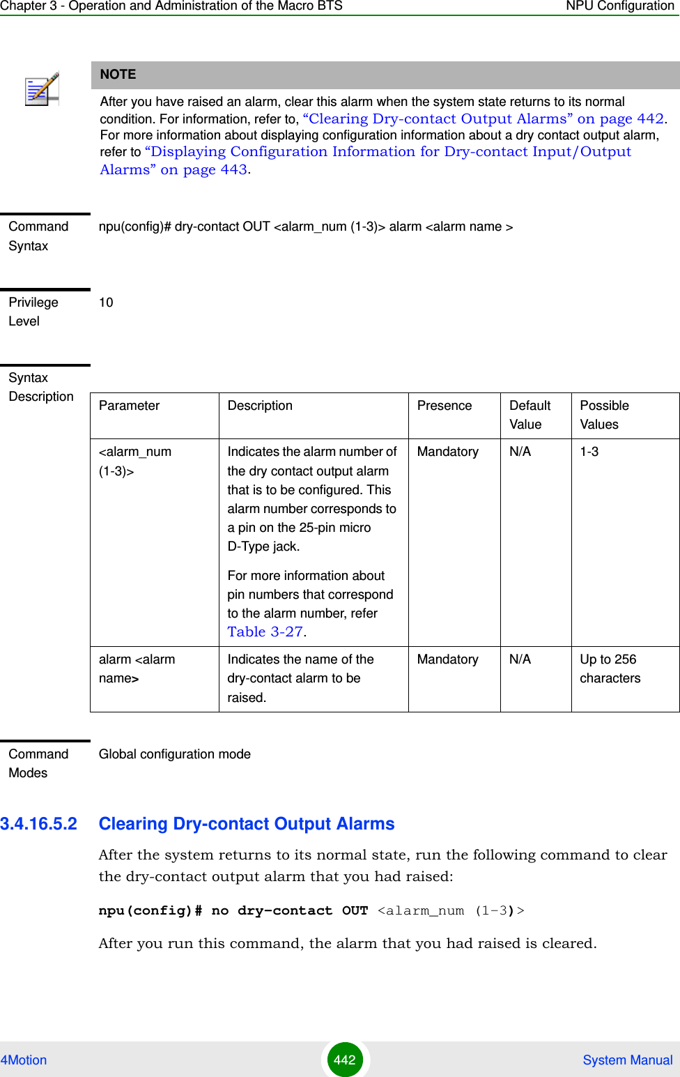
![Chapter 3 - Operation and Administration of the Macro BTS NPU Configuration4Motion 443 System Manual3.4.16.6 Displaying Configuration Information for Dry-contact Input/Output AlarmsTo display configuration information for dry-contact input/output alarms, run the following command:npu# show dry-contact {IN | OUT} [<alarm_num>]If you want to display configuration information for input or output alarms, specify IN or OUT. You can also specify the pin number if you want to view configuration information for particular pin used for connecting an external device to the 4Motion unit.For example, run the following command if you want to display configuration information for the dry contact input alarm connected to the 4Motion unit via pin# 8 on the NPU panel:npu# show dry-contact IN 8NOTENOTEFor more information about raising a dry contact output alarm, refer to “Raising Dry-contact Output Alarms” on page 441.Command Syntaxnpu(config)# no dry-contact OUT <alarm_num (1-3)>Privilege Level10Syntax Description Parameter Description Presence Default ValuePossible Values<alarm_num (1-3)>Indicates the alarm number of the dry contact output alarm alarm that is to be disabled. For more information about the pin numbers that correspond to the alarm number, refer Table 3-27.Mandatory N/A 1-3Command ModesGlobal configuration mode](https://usermanual.wiki/Alvarion-Technologies/MICRO-25.Manual-p4/User-Guide-1329245-Page-45.png)
![Chapter 3 - Operation and Administration of the Macro BTS NPU Configuration4Motion 444 System ManualIf you want to display configuration information for all dry contact IN alarms, run the following command:npu# show dry-contact INNOTEAn error may occur if you have specified an incorrect pin number for a particular input/output alarm. For more information about the correct pin-to-alarm number mapping, refer Table 3-26 and Table 3-27.Command Syntaxnpu# show dry-contact {IN | OUT} [<alarm_num>]Privilege Level1Syntax Description Parameter Description Presence Default ValuePossible Values{IN|OUT} Indicates whether configuration information is to be displayed for input or output alarms.Optional N/A INOUT[<alarm_num>] Denotes the alarm number of the input or output alarm for which configuration information is to be displayed.If you do not specify this value, configuration information is displayed for all input or output alarms.Refer Figure 3-2 and Figure 3-3 for more information about the numbers assigned to the pins used for connecting dry contact alarms.Optional N/A 1-8 for input alarms1-3 for output alarms](https://usermanual.wiki/Alvarion-Technologies/MICRO-25.Manual-p4/User-Guide-1329245-Page-46.png)
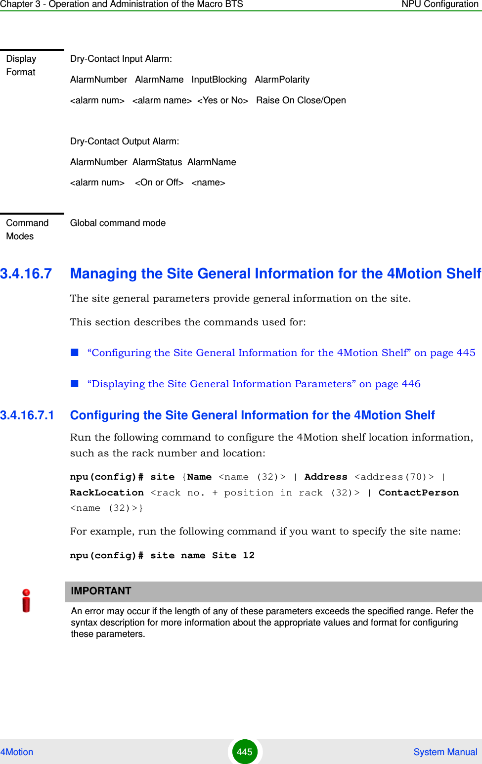
![Chapter 3 - Operation and Administration of the Macro BTS NPU Configuration4Motion 446 System Manual3.4.16.7.2 Displaying the Site General Information ParametersTo display configuration information for the site general information parameters, run the following command:npu# show site [{Name | Address | RackLocation | ContactPerson |ProductType}]In addition to the configurable parameter (see Section 3.4.16.7.1), you can also display the Product Type.If you want to display configuration information for one parameter, specify only the required parameter. If you want to display configuration information for all dry contact alarms, run the following command:npu# show siteCommand Syntaxnpu(config)# site (Name <name (32)> | Address <address(70)> | RackLocation <rack no. + position in rack (32)> | ContactPerson <name (32)>)Privilege Level10Syntax Description Parameter Description Presence Default ValuePossible ValuesName <name (256)>}Indicates the name of the 4Motion shelf.Optional N/A String (up to 32 characters)Address <address (256)>}Indicates the address of the 4Motion site. Optional N/A String (up to 70 characters)RackLocation <rack no. + position in rack (256)>}Indicates the rack number and location of the 4Motion shelf.Optional N/A String (up to 32 characters)ContactPerson <name (256)>Indicates the name of person who is administering the 4Motion shelf.Optional String (up to 32 characters)Command ModesGlobal configuration mode](https://usermanual.wiki/Alvarion-Technologies/MICRO-25.Manual-p4/User-Guide-1329245-Page-48.png)
![Chapter 3 - Operation and Administration of the Macro BTS NPU Configuration4Motion 447 System Manual3.4.16.8 Managing the Unique Identifier for the 4Motion ShelfThe Site Identifier (Site ID) is used by the management system as identifier of the site and must be unique in the managed network.The default value 0 is not a valid Site Identifier: it indicates that the Site Identifier was not configured and a valid Site Identifier must be configured. A BTS with Site Identifier 0 will not be discovered by AlvariSTAR.Since the Site Identifier is used by AlvariSTAR to identify the device, it is highly recommended not to modify it. If necessary, you must follow the Site Number Change process described in the AlvariSTAR Device Manager User Manual.This section describes the commands used for:“Configuring the Unique Identifier for the 4Motion Shelf” on page 447“Displaying the Unique Identifier for the 4Motion Shelf” on page 4483.4.16.8.1 Configuring the Unique Identifier for the 4Motion ShelfTo configure a unique identifier for the 4Motion shelf, run the following command:npu(config)# site identifier <site id <1-999999>>Command Syntaxnpu# show site [{Name | Address | RackLocation | ContactPerson |ProductType }]Privilege Level1Display Format (for all parameters)Name :Address :Rack Location :Contact Person :Product Type :Command ModesGlobal command mode](https://usermanual.wiki/Alvarion-Technologies/MICRO-25.Manual-p4/User-Guide-1329245-Page-49.png)
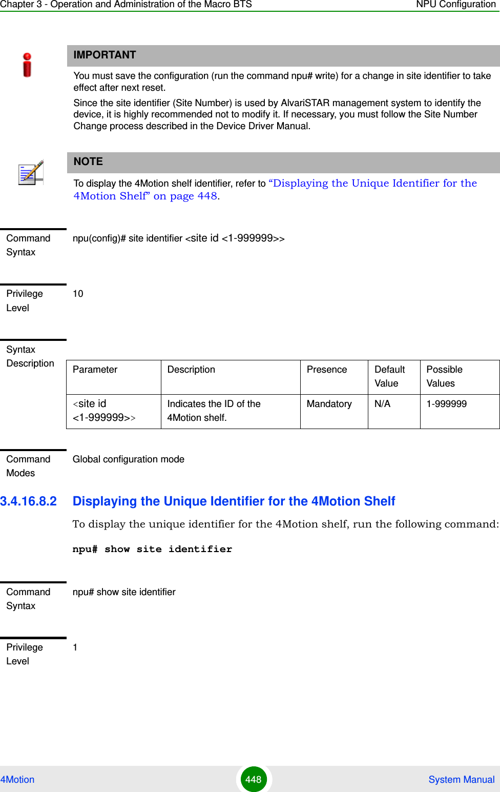
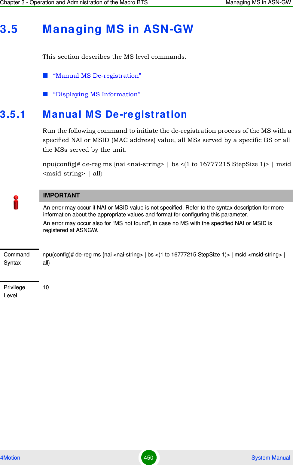
![Chapter 3 - Operation and Administration of the Macro BTS Managing MS in ASN-GW4Motion 451 System Manual3.5 .2 Displa ying MS InformationRun the following command to view the MS context information of all MSs or a single MS: npu# show ms info [detailed [{nai|msid}<string>]] [hotlined]Syntax Description Parameter Description Presence Default ValuePossible Values{nai <nai-string> |bs <(1 to 16777215 StepSize 1)> | msid <msid-string> | all}Initiates the de-registration of one or several MSs:nai <nai-string>: de-register the MS with the specified NAI value.bs <(1 to 16777215 StepSize 1)>: de-register all MSs served by the specified BS.msid <msid-string>: de-register the MS with the specified MSID (MAC address) value. The format is xx:xx:xx:xx:xx:xx.all: de-register all MSs served by the unit.Mandatory N/A StringCommand ModesGlobal configuration modeIMPORTANTAn error may occur if invalid NAI or invalid MSID is provided. Refer to the syntax description for more information about the appropriate values and format for configuring this parameter.Command Syntaxnpu# show ms info [detailed [{nai|msid}<string>]] [hotlined]Privilege Level1](https://usermanual.wiki/Alvarion-Technologies/MICRO-25.Manual-p4/User-Guide-1329245-Page-53.png)
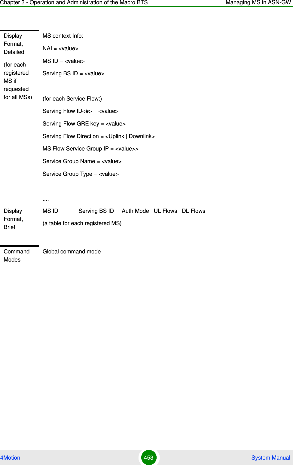
![Chapter 3 - Operation and Administration of the Macro BTS Managing MS in ASN-GW4Motion 452 System ManualSyntax Description Parameter Description Presence Default ValuePossible Values[detailed [{nai|msid}<string>]] [hotlined]Defines the type of information to be displayed:Null (the command show ms info): Displays brief info for all MSs.detailed (the command show ms info detailed): Displays detailed info for all MSs.detailed nai <string> (the command show ms info detailed nai <string>): Displays detailed info for the MS with the specified NAI.detailed msid <string> (the command show ms info detailed msid <string>): Displays detailed info for the MS with the specified MSID (MAC address). The MSID format is xx:xx:xx:xx:xx:xx. hotlined (the command show ms info hotlined): Displays brief info for all hotlined MSs.Optional Null Nulldetaileddetailed nai <string>detailed msid <string>hotlined](https://usermanual.wiki/Alvarion-Technologies/MICRO-25.Manual-p4/User-Guide-1329245-Page-54.png)
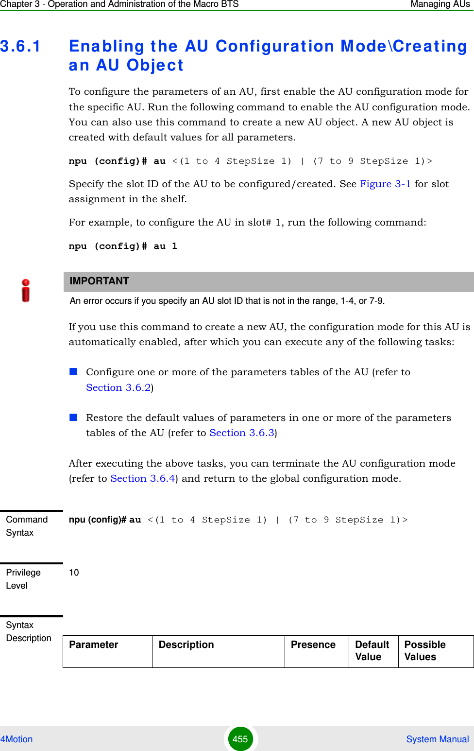
![Chapter 3 - Operation and Administration of the Macro BTS Managing AUs4Motion 454 System Manual3.6 Ma na ging AU sUp to seven AU objects can be created and configured, corresponding to the AU cards that can be installed in slots 1-4, 7-9 of the shelf.1Enable the AU configuration mode for the selected AU (refer to Section 3.6.1)2You can now execute any of the following tasks:»Configure one or more of the parameters tables of the AU (refer to Section 3.6.2)»Restore the default values of parameters in one or more of the parameters tables of the AU (refer to Section 3.6.3)3Terminate the AU configuration mode (refer to Section 3.6.4)In addition, you can, at any time, display configuration and status information for each of the parameters tables of the AU (refer to Section 3.6.6) or delete an existing AU object (refer to Section 3.4.12.7.5). To configure an AU:NOTEThe AU reserved parameters table enables configuring up to 9 parameters that are reserved for possible future use. In the current release none of the reserved parameters is being used. Therefore, the following commands are not applicable:Configure reserved parameters: npu(config-au-<N>)# au-reserved [reserved-1 <string (32)>] [reserved-2 <string (32)>] [reserved-3 <string (32)>] [reserved-4 <string (32)>] [reserved-5 <string (32)>] [reserved-6 <string (32)>] [reserved-7 <string (32)>] [reserved-8 <string (32)>] [reserved-9 <string (32)>]Restore default values of reserved parameters: npu(config-au-<N>)# no au-reserved [reserved-1] [reserved-2] [reserved-3] [reserved-4] [reserved-5] [reserved-6] [reserved-7] [reserved-8] [reserved-9].Display configured values of reserved parameters: npu# show au-reserved au [<(1 to 4 StepSize 1) | (7 to 9 StepSize 1)>].](https://usermanual.wiki/Alvarion-Technologies/MICRO-25.Manual-p4/User-Guide-1329245-Page-56.png)
![Chapter 3 - Operation and Administration of the Macro BTS Managing AUs4Motion 456 System Manual3.6 .2 Configuring AU Pa ra m e t e rsAfter enabling the AU configuration mode you can configure the following parameters tables:Properties (refer to Section 3.6.2.1)Control (refer to Section 3.6.2.2)Connectivity (refer to Section 3.6.2.3)3.6.2.1 Configuring PropertiesThe properties table enables configuring the main properties of the required AU card and controlling the power on each of the AU’s ODU ports.To configure the properties parameters, run the following command:npu(config-au-1)# properties [required-type <au4x4Modem |au2x2>] [port-1-power {shutDown | noShutDown}] [port-2-power {shutDown | noShutDown}] [port-3-power {shutDown | noShutDown}] [port-4-power {shutDown | noShutDown}]<(1 to 4 StepSize 1) | (7 to 9 StepSize 1)>The slot ID of the AU to be configuredMandatory N/A 1-47-9Command ModesGlobal configuration modeNOTEThe following examples are for au configuration mode for au-1.NOTEYou can display configuration information for the AU properties. For details, refer to Section 3.6.6.1.IMPORTANTAn error may occur if you provide an invalid value for any of these parameters. Refer the syntax description for more information about the appropriate values and format for configuring these parameters.](https://usermanual.wiki/Alvarion-Technologies/MICRO-25.Manual-p4/User-Guide-1329245-Page-58.png)
![Chapter 3 - Operation and Administration of the Macro BTS Managing AUs4Motion 457 System Manual3.6.2.2 Configuring the Control ParameterThe control parameters enables controlling the operation of the AU.To configure the control parameter, run the following command:npu(config-au-1)# control shutdown-operation {normalOperation | reset | shutdown} Command Syntaxnpu(config-au-1)# properties [required-type <au4x4Modem | au2x2> ] [port-1-power {shutDown | noShutDown} ] [port-2-power {shutDown | noShutDown} ] [port-3-power {shutDown | noShutDown} ] [port-4-power {shutDown | noShutDown} ]Privilege Level10Syntax Description Parameter Description Presence Default ValuePossible Values[required-type <au4x4Modem |au2x2>Defines the AU card configuration required: 4-ports or 2-ports. 2-ports AU is applicable only for Macro Outdoor.Optional au4x4Modemau4x4Modemau2x2[port-1-power {shutDown | noShutDown} ]Controls power from AU card port 1 to ODUOptional No ShutdownshutDownnoShutDown[port-2-power {shutDown | noShutDown} ]Controls power from AU card port 2 to ODU.Optional No ShutdownshutDownnoShutDown[port-3-power {shutDown | noShutDown |} ]Controls power from AU card port 3 to ODU. Not applicable for a 2-ports AU.Optional No ShutdownshutDownnoShutDown[port-4-power {shutDown | noShutDown} ]Controls power from AU card port 4 to ODU. Not applicable for a 2-ports AU.Optional No ShutdownshutDownnoShutDownCommand Modesau configuration mode](https://usermanual.wiki/Alvarion-Technologies/MICRO-25.Manual-p4/User-Guide-1329245-Page-59.png)
![Chapter 3 - Operation and Administration of the Macro BTS Managing AUs4Motion 458 System Manual3.6.2.3 Configuring AU ConnectivityThe connectivity tables enables configuring the connectivity parameters for the Ethernet interface of the AU. In the current release the interface operates in 802.1q mode: In this mode, the interface accepts only VLAN-tagged packets. All packets received without VLAN tags are dropped.The connectivity tables enable also configuring the parameters of the service interface (excluding the VLAN ID) used by the AU for uploading maintenance information to an external server (the same VLAN ID is used by all service interfaces - for details see Section 3.4.3).To configure the connectivity parameters, run the following command:npu(config-au-1)# connectivity [maxframesize <(1518 to 9000 StepSize 1)>] [bearervlanid <(9 to 9 StepSize 1) | (11 to 100 StepSize 1) |(110 to 4094 StepSize 1)>] [service-ip <ip address> ] [service-mask <ip address> ] [service-next-hop <ip address> ]Command Syntaxnpu(config-au-1)# control shutdown-operation {normalOperation | reset | shutdown}Privilege Level10Syntax Description Parameter Description Presence Default ValuePossible Valuesshutdown-operation {normalOperation | reset | shutdown}Controls the operation of the AU card: Normal Operation, Shutdown (disable power to card) or Reset.Mandatory normal OperationnormalOperationresetshutdownCommand Modesau configuration mode](https://usermanual.wiki/Alvarion-Technologies/MICRO-25.Manual-p4/User-Guide-1329245-Page-60.png)
![Chapter 3 - Operation and Administration of the Macro BTS Managing AUs4Motion 459 System ManualCommand Syntaxnpu (config-au-1)# connectivity [maxframesize <(1518 to 9000 StepSize 1)>] [bearervlanid <(9 to 9 StepSize 1) | (11 to 100 StepSize 1) |(110 to 4094 StepSize 1)>] [service-ip <ip address> ] [service-mask <ip address> ] [service-next-hop <ip address> ]Privilege Level10Syntax Description Parameter Description Presence Default ValuePossible Values[maxframesize <(1518 to 9000 StepSize 1)>]The maximum frame size (in Bytes) that can be accepted on the Ethernet interface of the AU. Larger packets will be dropped.In 802.1q encapsulation mode the actual minimal frame size (including VLAN tag) is 1522 bytes, which is also the default.Must be configured to the same value as the mtu parameter for this interface in the NPU.Optional 1522 1518 to 9000[bearervlanid <(9 to 9 StepSize 1) | (11 to 100 StepSize 1) |(110 to 4094 StepSize 1)>]The VLAN ID of packets on the Ethernet interface of the AU. It must be configured to the same value as the if_vlan parameter of the bearer interface in the NPU. Note that VLAN 10 is used for internal management and cannot be used the bearer VLAN.Optional 11 9, 11-100, 110-4094[service-ip <ip address> ]The IP address of the service interface. Must be unique in the network.Optional 192.168.0.1IP address[service-mask <ip address> ]The subnet mask of the service interface.Optional 255.255.255.0subnet mask](https://usermanual.wiki/Alvarion-Technologies/MICRO-25.Manual-p4/User-Guide-1329245-Page-61.png)
![Chapter 3 - Operation and Administration of the Macro BTS Managing AUs4Motion 460 System Manual3.6 .3 Restoring Default Value s for AU Configurat ion Pa ra m e t e r sAfter enabling the AU configuration mode you can restore the default values for parameters in the following parameters tables:Properties (refer to Section 3.6.3.1)Control (refer to Section 3.6.3.2)Connectivity (refer to Section 3.6.3.3)3.6.3.1 Restoring the Default Values of Properties ParametersTo restore the some or all of the Properties parameters to their default value, run the following command:npu(config-au-1)# no properties [required-type] [port-1-power] [port-2-power] [port-3-power] [port-4-power]You can restore only selected parameters to their default value by specifying only those parameter. For example, to restore only the port-1-power to the default value, run the following command:npu(config-au-1)# no properties port-1-powerThe parameter will be restored to its default value, while the other parameters will remain unchanged.To restore all properties parameters to their default value, run the following command:npu(config-au-1)# no properties[service-next-hop <ip address> ]The default gateway IP address of the service interface.Optional 0.0.0.0 (none)IP addressCommand Modesau-1 configuration modeNOTERefer to Section 3.6.2.1 for a description and default values of these parameters.](https://usermanual.wiki/Alvarion-Technologies/MICRO-25.Manual-p4/User-Guide-1329245-Page-62.png)
![Chapter 3 - Operation and Administration of the Macro BTS Managing AUs4Motion 461 System Manual3.6.3.2 Restoring the Default Value of the Control ParameterTo restore the Control parameter to the default value (normalOperation), run the following command:npu(config-au-1)# no control3.6.3.3 Restoring the Default Values of Connectivity ParametersTo restore Connectivity parameters do their default value, run the following command:npu(config-au-1)# no connectivity [maxframesize] [bearervlanid] [service-ip] [service-mask] [service-next-hop]You can restore only one of the parameters to its default value by specifying only that parameter. For example, to restore only the maximum frame size to the default (1522), run the following command:npu(config-au-1)# no connectivity maxframesizeThe maximum frame size will be restored to its default value, while the other parameters will remain unchanged.To restore both parameters to their default value, run the following command:Command Syntaxnpu(config-au-1)# no properties [required-type] [port-1-power] [port-2-power] [port-3-power] [port-4-power]Privilege Level10Command Modesau configuration modeCommand Syntaxnpu(config-au-1)# no controlPrivilege Level10Command ModesGlobal configuration mode](https://usermanual.wiki/Alvarion-Technologies/MICRO-25.Manual-p4/User-Guide-1329245-Page-63.png)
![Chapter 3 - Operation and Administration of the Macro BTS Managing AUs4Motion 462 System Manualnpu(config-au-1)# no connectivity3.6 .4 Terminating the AU Configurat ion M odeRun the following command to terminate the au configuration mode:npu(config-au-1)# exit3.6 .5 De leting an AU ObjectRun the following command to delete an AU object:npu(config)# no au <(1 to 4 StepSize 1) | (7 to 9 StepSize 1)>NOTERefer to Section 3.6.2.3 for a description and default values of these parameters.Command Syntaxnpu(config-au-1)# no connectivity [maxframesize] [bearervlanid] [service-ip] [service-mask] [service-next-hop]Privilege Level10Command Modesau configuration modeCommand Syntaxnpu(config-au-1)# exitPrivilege Level10Command Modesau-1 configuration modeIMPORTANTAn associated AU (specified in a Sector Association) cannot be deleted.](https://usermanual.wiki/Alvarion-Technologies/MICRO-25.Manual-p4/User-Guide-1329245-Page-64.png)
![Chapter 3 - Operation and Administration of the Macro BTS Managing AUs4Motion 463 System Manual3.6 .6 Displa ying Configurat ion a nd Stat us I nfor m at ion for AU Pa ra m e t e rsYou can display the current configuration and (where applicable) additional status information for the following parameters tables:Properties (refer to Section 3.6.6.1)Control (refer to Section 3.6.6.2)Connectivity (refer to Section 3.6.6.3)3.6.6.1 Displaying Configuration and Status Information for AU PropertiesTo display configuration and status information for the properties of a specific or all AU objects, run the following command: npu# show properties au [<(1 to 4 StepSize 1) | (7 to 9 StepSize 1)>]Specify the au slot ID (1-4, 7-9) if you want to display configuration and status information for a particular AU. Do not specify a value for this parameter if you want to view configuration and status information for all existing AU objects.Command Syntaxnpu(config)# no au <(1 to 4 StepSize 1) | (7 to 9 StepSize 1)>Privilege Level10Syntax Description Parameter Description Presence Default ValuePossible Values <(1 to 4 StepSize 1) | (7 to 9 StepSize 1)>The slot ID of the AU card Mandatory N/A 1-4, 7-9Command ModesGlobal configuration mode](https://usermanual.wiki/Alvarion-Technologies/MICRO-25.Manual-p4/User-Guide-1329245-Page-65.png)
![Chapter 3 - Operation and Administration of the Macro BTS Managing AUs4Motion 464 System ManualCommand Syntaxnpu# show properties au [<(1 to 4 StepSize 1) | (7 to 9 StepSize 1)>]Privilege Level1Syntax Description Parameter Description Presence Default ValuePossible Values[<(1 to 4 StepSize 1) | (7 to 9 StepSize 1)>]The slot ID of the AU Specify a value for this parameter if you want to display the properties of a specific AU. Do not specify a value for this parameter if you want to display the properties of all AUs.Optional N/A 1-4, 7-9Display Format(for each existing AU object if requested for all AUs)SlotNo. :<value>RequiredType :<value>InstalledStatus :<value>InstalledType :<value> (0 for notinstalled AU)HWVersion :<value> (null for notinstalled AU)HWRevision :<value> (null for notinstalled AU)SerialNo. :<value> (null for notinstalled AU)BootVersion :<value> (null for notinstalled AU)IFVersion :<value> (null for notinstalled AU)IFRevision :<value> (null for notinstalled AU)Port1PowertoODU :<value>Port2PowertoODU :<value>Port3PowertoODU :<value>Port4PowertoODU :<value>Command ModesGlobal command mode](https://usermanual.wiki/Alvarion-Technologies/MICRO-25.Manual-p4/User-Guide-1329245-Page-66.png)
![Chapter 3 - Operation and Administration of the Macro BTS Managing AUs4Motion 465 System ManualIn addition to the configurable parameters, the following status parameters are also displayed:3.6.6.2 Displaying Configuration for AU ControlTo display configuration for the Control parameter of a specific or all AU objects, run the following command: npu# show control au [<(1 to 4 StepSize 1) | (7 to 9 StepSize 1)>]Specify the au slot ID (1-4, 7-9) if you want to display configuration information for a particular AU. Do not specify a value for this parameter if you want to view configuration information for all existing AU objects.Parameter Description Possible ValuesInstalledStatus Indicates whether an AU card is installed in the slot.Following parameters are applicable only for installed AU.installed (1)notinstalled (0)InstalledType The AU Type. auNotDetected (0)au4x4Modem (4)au2x2 (6)HWVersion AU HW Version number <number>HWRevision AU HW Revision number <number>SerialNo. AU Serial number <number>BootVersion AU Boot SW Version number <string>IFVersion AU IF Version number <number>IFRevision AU HW Revision number <number>Command Syntaxnpu# show control au [<(1 to 4 StepSize 1) | (7 to 9 StepSize 1)>]Privilege Level1](https://usermanual.wiki/Alvarion-Technologies/MICRO-25.Manual-p4/User-Guide-1329245-Page-67.png)
![Chapter 3 - Operation and Administration of the Macro BTS Managing AUs4Motion 466 System Manual3.6.6.3 Displaying Configuration Information for AU Connectivity ParametersTo display configuration information for the connectivity parameters of a specific or all AU objects, run the following command: npu# show connectivity au [<(1 to 4 StepSize 1) | (7 to 9 StepSize 1)>]Specify the au slot ID (1-4, 7-9) if you want to display configuration for a particular AU. Do not specify a value for this parameter if you want to view configuration for all existing AU objects.The displayed information includes also configured values for relevant parameters that are configured for the internal management interface of the NPU.Syntax Description Parameter Description Presence Default ValuePossible Values[<(1 to 4 StepSize 1) | (7 to 9 StepSize 1)>]The slot ID of the AU Specify a value for this parameter if you want to display the control parameter of a specific AU. Do not specify a value for this parameter if you want to display the control parameters of all AUs.Optional N/A 1-4, 7-9Display Format(for each existing AU object if requested for all AUs)SlotNo. :<value>AUPowerControl :<value>Command ModesGlobal command modeCommand Syntaxnpu# show connectivity au [<(1 to 4 StepSize 1) | (7 to 9 StepSize 1)>]](https://usermanual.wiki/Alvarion-Technologies/MICRO-25.Manual-p4/User-Guide-1329245-Page-68.png)
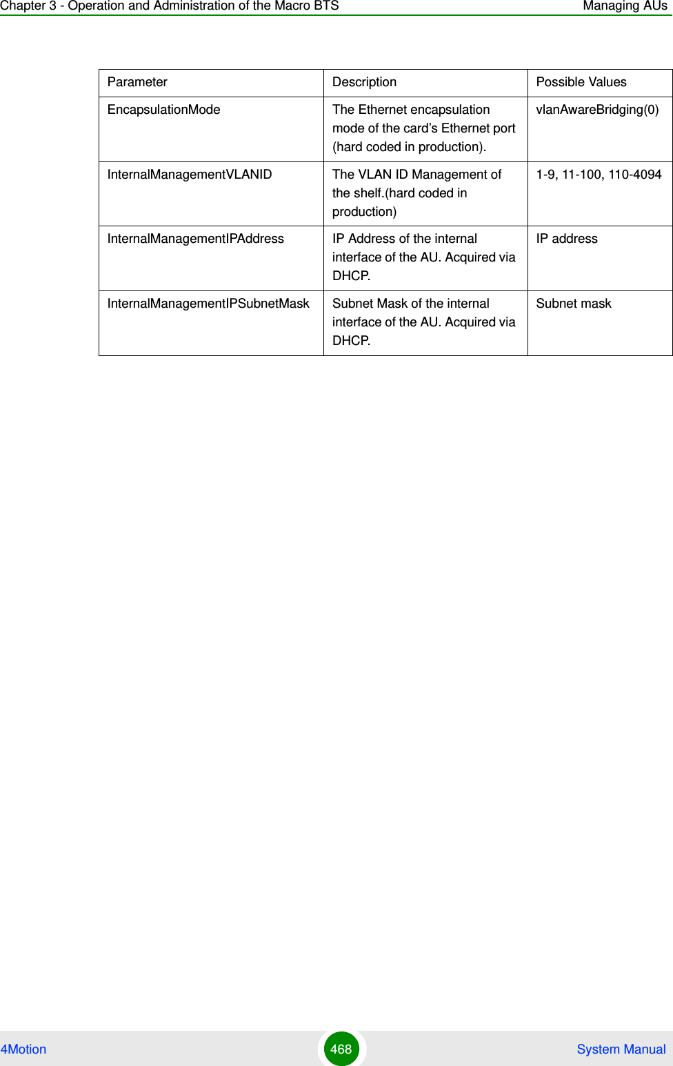
![Chapter 3 - Operation and Administration of the Macro BTS Managing AUs4Motion 467 System ManualIn addition to the configurable parameters, the following status parameters are also displayed:Privilege Level1Syntax Description Parameter Description Presence Default ValuePossible Values[<(1 to 4 StepSize 1) | (7 to 9 StepSize 1)>]The slot ID of the AU Specify a value for this parameter if you want to display the connectivity parameters of a specific AU. Do not specify a value for this parameter if you want to display the connectivity parameters of all AUs.Optional N/A 1-4, 7-9Display Format(for each existing AU object if requested for all AUs)SlotNo. :<value>EncapsulationMode :vlanAwareBridging(0)MaxFrameSize(Bytes) :<value>InternalManagementVLANID :<value>BearerVLANID :<value>InternalManagementIPAddress :<value>InternalManagementIPSubnetMask :<value>ServiceInterfaceIPAddress :<value>ServiceInterfaceIPSubnetMask :<value>ServiceInterfaceIpnexthop :<value>Command ModesGlobal command mode](https://usermanual.wiki/Alvarion-Technologies/MICRO-25.Manual-p4/User-Guide-1329245-Page-69.png)
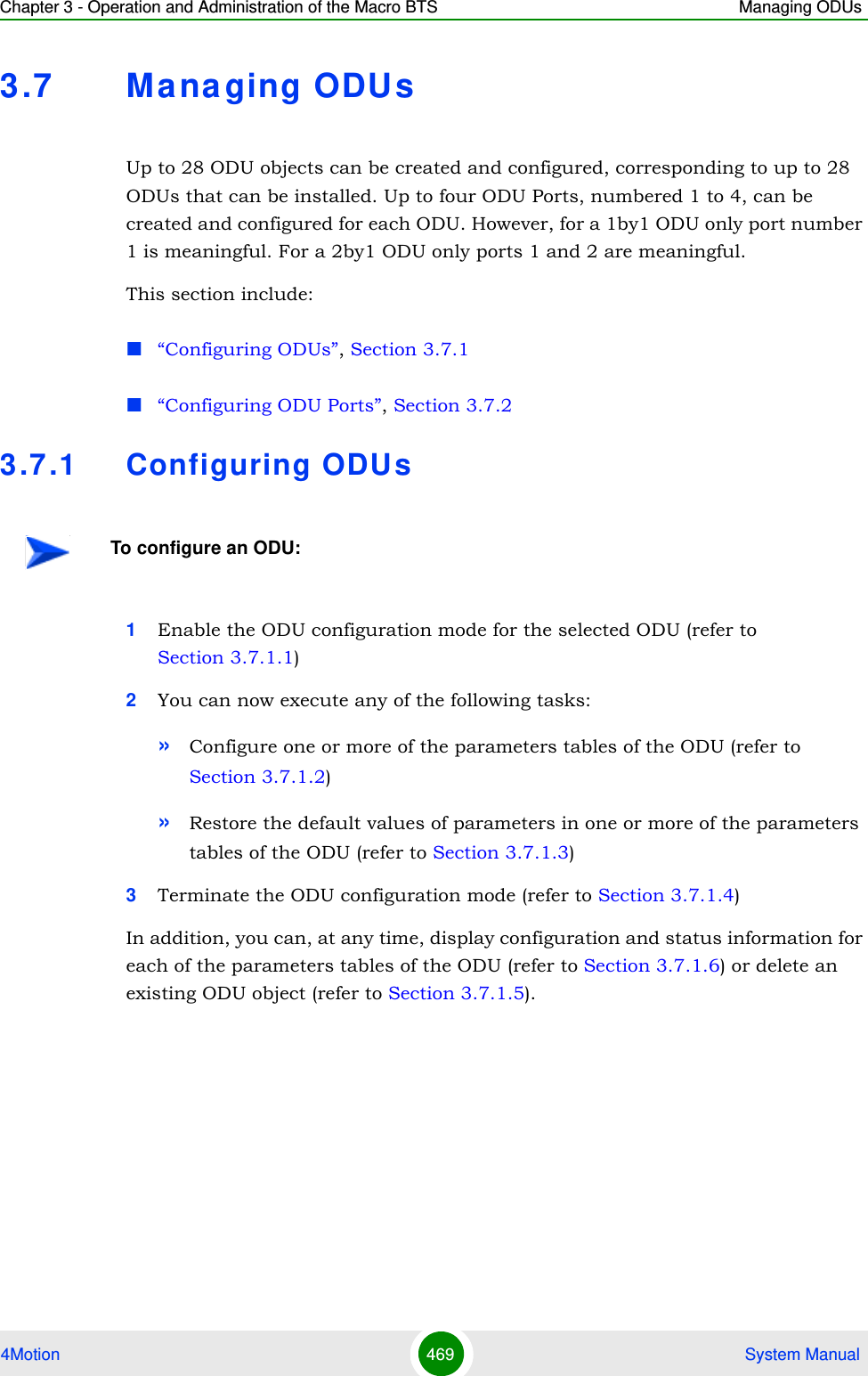
![Chapter 3 - Operation and Administration of the Macro BTS Managing ODUs4Motion 470 System Manual3.7.1.1 Enabling the ODU Parameters Configuration Mode\Creating an ODU ObjectTo configure the parameters of an ODU, first enable the ODU parameters configuration mode for the specific ODU. Run the following command to enable the ODU parameters configuration mode for an existing ODU object:npu (config)# odu-params <(1 to 28 StepSize 1)>To create a new ODU object, the mandatory required-odu-type parameter must be specified. Run the following command to create a new ODU object and enable the parameters configuration mode for this ODU:npu (config)# odu-params <(1 to 28 StepSize 1)> required-odu-type {<a list of ODU types>)}A new ODU object is created with default values for all parameters except to the mandatory required-odu-type parameter.For example, to create an ODU 1 object and enable the parameters configuration mode for this ODU, where the required odu type is oDU23002360000N361by1N0, run the following command:npu (config)# odu-params 1 required-odu-type oDU23002360000N361by1N0NOTEThe ODU reserved parameters table enables configuring up to 9 parameters that are reserved for possible future use. In the current release none of the reserved parameters is being used. Therefore, the following commands are not applicable:Configure reserved parameters: npu(config-odu-params-<N>)# odu-reserved [reserved-1 <string (32)>] [reserved-2 <string (32)>] [reserved-3 <string (32)>] [reserved-4 <string (32)>] [reserved-5 <string (32)>] [reserved-6 <string (32)>] [reserved-7 <string (32)>] [reserved-8 <string (32)>] [reserved-9 <string (32)>].Restore default values of reserved parameters: npu(config-odu-params-<N>)# no odu-reserved [reserved-1] [reserved-2] [reserved-3] [reserved-4] [reserved-5] [reserved-6] [reserved-7] [reserved-8] [reserved-9].Display configured values of reserved parameters: npu# show odu-reserved [odu-no <(1 to 28 StepSize 1)>].IMPORTANTAn error may occur if you provide an invalid value for any of these parameters. Refer the syntax description for more information about the appropriate values and format for configuring these parameters.](https://usermanual.wiki/Alvarion-Technologies/MICRO-25.Manual-p4/User-Guide-1329245-Page-72.png)
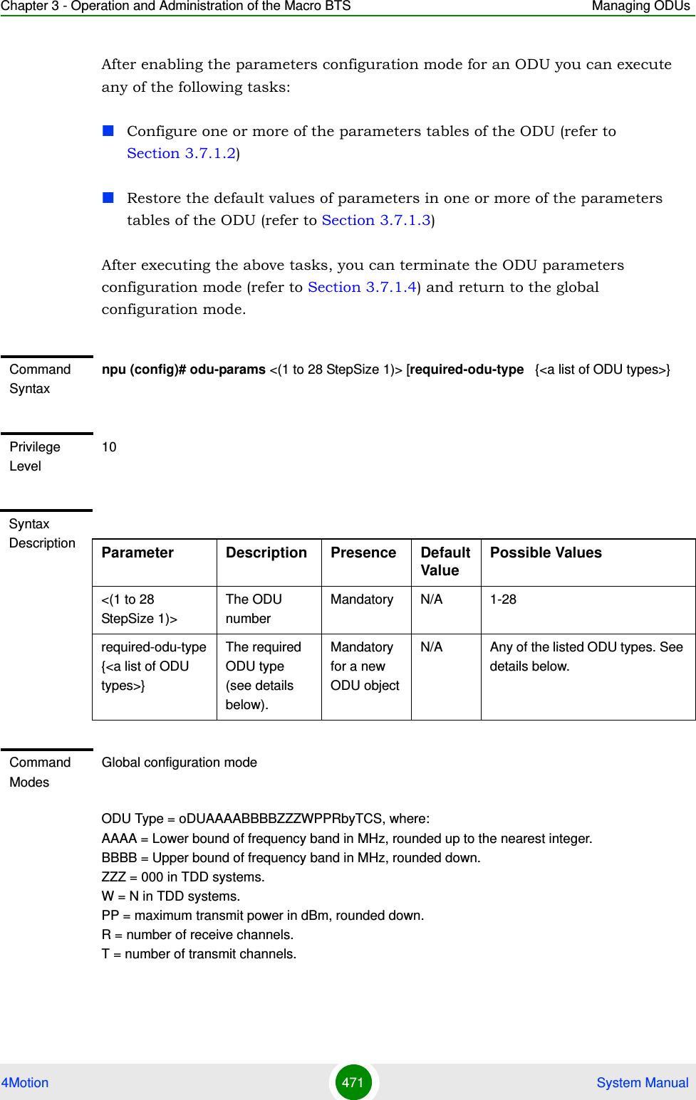
![Chapter 3 - Operation and Administration of the Macro BTS Managing ODUs4Motion 472 System ManualC = Y if cavity filter is present, N if not. S = Reserved (0).x3.7.1.2 Configuring ODU ParametersAfter enabling the ODU parameters configuration mode you can configure the General ODU parameters.The general ODU parameters table enables configuring the main properties of the required ODU.To configure the general ODU parameters, run the following command:npu(config-odu-params-1)# odu-general [external-cavity-filter-existence {TRUE | FALSE} ] [required-odu-type {<a list of ODU types>} ]NOTE1 The list includes ODUs that are not available yet.2 For oDU23052360000N361by1Y0 that includes a WCS filter, the actually supported frequency band is 2305 - 2317, 2348 - 2360 MHz.3 For the oDU24852690000N384by2NO the maximum supported transmit power in the 2485-2495 MHz band is 37 dBm.NOTEThe following examples are for odu-1 parameters configuration mode.NOTEYou can display configuration information for the ODU general parameters. For details, refer to Section 3.7.1.6.IMPORTANTAn error may occur if you provide an invalid value for any of these parameters. Refer the syntax description for more information about the appropriate values and format for configuring these parameters.Command Syntaxnpu(config-odu-params-1)# odu-general [external-cavity-filter-existence {TRUE | FALSE} ] [required-odu-type {<a list of ODU types} ]](https://usermanual.wiki/Alvarion-Technologies/MICRO-25.Manual-p4/User-Guide-1329245-Page-74.png)
![Chapter 3 - Operation and Administration of the Macro BTS Managing ODUs4Motion 473 System Manual3.7.1.3 Restoring Default Values for ODU Configuration ParametersAfter enabling the ODU parameters configuration mode you can restore the default values for the external-cavity-filter-existence parameter.To restore the general external-cavity-filter-existence parameter to the default value, run the following command:npu(config-odu-params-1)# no odu-general [external-cavity-filter-existence]The parameter will be restored to its default value, while the other parameters will remain unchanged.Privilege Level10Syntax Description Parameter Description Presence Default ValuePossible Values[external-cavity-filter-existence {TRUE | FALSE}]Informational parameter indicating whether an external cavity filter for the ODU exists. Optional FALSE TRUEFALSE[required-odu-type {...} ]The required ODU type. For more details refer to Section 3.7.1.1Optional The previously configured valueFor details refer to Section 3.7.1.1Command Modesodu-params configuration modeNOTERefer to Section 3.7.1.2 for a description and default value of this parameter.Command Syntaxnpu(config-odu-params-1)# no odu-general [external-cavity-filter-existence]Privilege Level10](https://usermanual.wiki/Alvarion-Technologies/MICRO-25.Manual-p4/User-Guide-1329245-Page-75.png)

![Chapter 3 - Operation and Administration of the Macro BTS Managing ODUs4Motion 475 System Manual3.7.1.6 Displaying Configuration and Status Information for ODU ParametersYou can display the current configuration and (where applicable) additional status information for the ODU general parameters.To display configuration and status information for the general parameters of a specific or all ODU objects, run the following command: npu# show odu-general [odu-no <(1 to 28 StepSize 1)>]Specify the ODU number (1-28) if you want to display configuration and status information for a particular ODU. Do not specify a value for this parameter if you want to view configuration and status information for all existing ODU objects.Command ModesGlobal configuration modeCommand Syntaxnpu# show odu-general [odu-no <(1 to 28 StepSize 1)> ]Privilege Level1Syntax Description Parameter Description Presence Default ValuePossible Values[odu-no <(1 to 28 StepSize 1)> ]The number of the ODU Specify a value for this parameter if you want to display the general parameters of a specific ODU. Do not specify a value for this parameter if you want to display the general parameters of all ODUs.Optional N/A 1-28](https://usermanual.wiki/Alvarion-Technologies/MICRO-25.Manual-p4/User-Guide-1329245-Page-77.png)
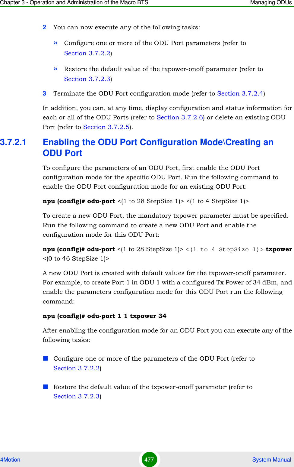
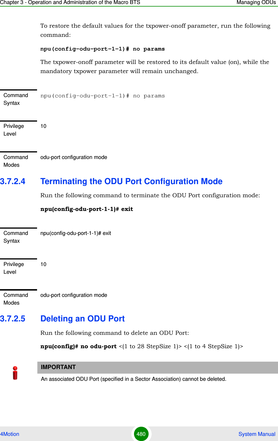
![Chapter 3 - Operation and Administration of the Macro BTS Managing ODUs4Motion 478 System ManualAfter executing the above tasks, you can terminate the ODU Port configuration mode (refer to Section 3.7.2.4) and return to the global configuration mode.3.7.2.2 Configuring ODU Port ParametersAfter enabling the ODU Port configuration mode you can configure the transmit power parameters of the port.To configure the ODU Port parameters, run the following command:npu(config-odu-port-1-1)# params [txpower <(0 to 46 StepSize 1)> ] [txpower-onoff {on | off} ]Command Syntaxnpu (config)# odu-port <(1 to 28 StepSize 1)> <(1 to 4 StepSize 1)> [txpower <(0 to 46 StepSize 1)>]Privilege Level10Syntax Description Parameter Description Presence Default ValuePossible Values<(1 to 28 StepSize 1)> The ODU number Mandatory N/A 1-28<(1 to 4 StepSize 1)> The Port number. Mandatory N/A 1-4[txpower <(0 to 46 StepSize 1)>]The required tx power at the specified ODU Port, in dBm.The actually available range depends on ODU Type: The upper limit is set by the Maximum Tx Power supported by the ODU. The control range for all ODUs is 10dBm. The AU will reject a value that is outside this range.Mandatory for a new ODU PortN/A 0 to 46 in increments of 1Command ModesGlobal configuration modeNOTEThe following examples are for odu-1, port-1 configuration mode.](https://usermanual.wiki/Alvarion-Technologies/MICRO-25.Manual-p4/User-Guide-1329245-Page-80.png)
![Chapter 3 - Operation and Administration of the Macro BTS Managing ODUs4Motion 479 System Manual3.7.2.3 Restoring Default Values for ODU Port ParametersAfter enabling the ODU Port configuration mode you can restore the default values for the txpower-onoff parameter:NOTEYou can display configuration information for the ODU Port parameters. For details, refer to Section 3.7.2.6.IMPORTANTAn error may occur if you provide an invalid value for any of these parameters. Refer the syntax description for more information about the appropriate values and format for configuring these parameters.Command Syntaxnpu(config-odu-port-1-1)# params [txpower <(0 to 46 StepSize 1)>] [txpower-onoff {on | off} ]Privilege Level10Syntax Description Parameter Description Presence Default ValuePossible Values[txpower <(0 to 46 StepSize 1)>]The transmit power at the ODU Port, in dBm. Optional As configured previously0 to 46 in increments of 1Actual range depends on ODU type.[txpower-onoff {on | off} ]Enables or disables transmissions on this port. Optional on onoffCommand Modesodu-port configuration modeIMPORTANTDo not disable transmission on any of the ODU ports. If needed, transmission can be disabled by shutting down the applicable AU port (see Section 3.6.2.1).](https://usermanual.wiki/Alvarion-Technologies/MICRO-25.Manual-p4/User-Guide-1329245-Page-81.png)
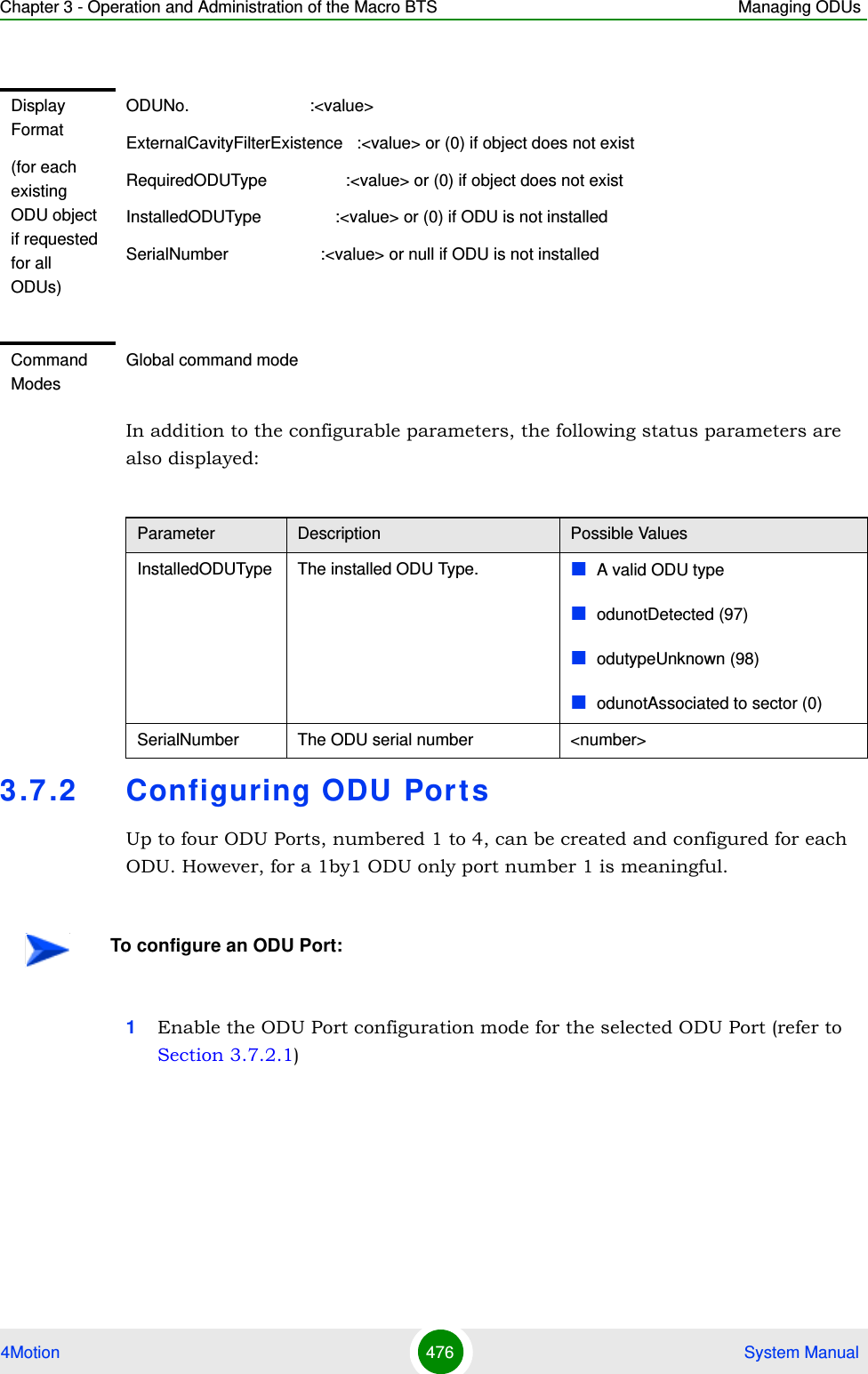
![Chapter 3 - Operation and Administration of the Macro BTS Managing ODUs4Motion 481 System Manual3.7.2.6 Displaying Configuration and Status Information for ODU PortsTo display configuration and status information of a specific or all ODU Ports, run the following command: npu# show odu-port [odu-no <(1 to 28 StepSize 1)> port-no <(1 to 4 StepSize 1)>]Specify the ODU number (1-28) and Port number (1-4) if you want to display configuration and status information for a particular ODU Port. Do not specify values for these parameters if you want to view configuration and status information for all existing ODU Ports.Command Syntaxnpu(config)# no odu-params <(1 to 28 StepSize 1)> <(1 to 4 StepSize 1)>Privilege Level10Syntax Description Parameter Description Presence Default ValuePossible Values<(1 to 28 StepSize 1)> The ODU number Mandatory N/A 1-28<(1 to 4 StepSize 1)> The Port number Mandatory N/A 1-4Command ModesGlobal configuration modeCommand Syntaxnpu# show odu-port [odu-no <(1 to 28 StepSize 1)> port-no <(1 to 4 StepSize 1)> ]Privilege Level1](https://usermanual.wiki/Alvarion-Technologies/MICRO-25.Manual-p4/User-Guide-1329245-Page-83.png)
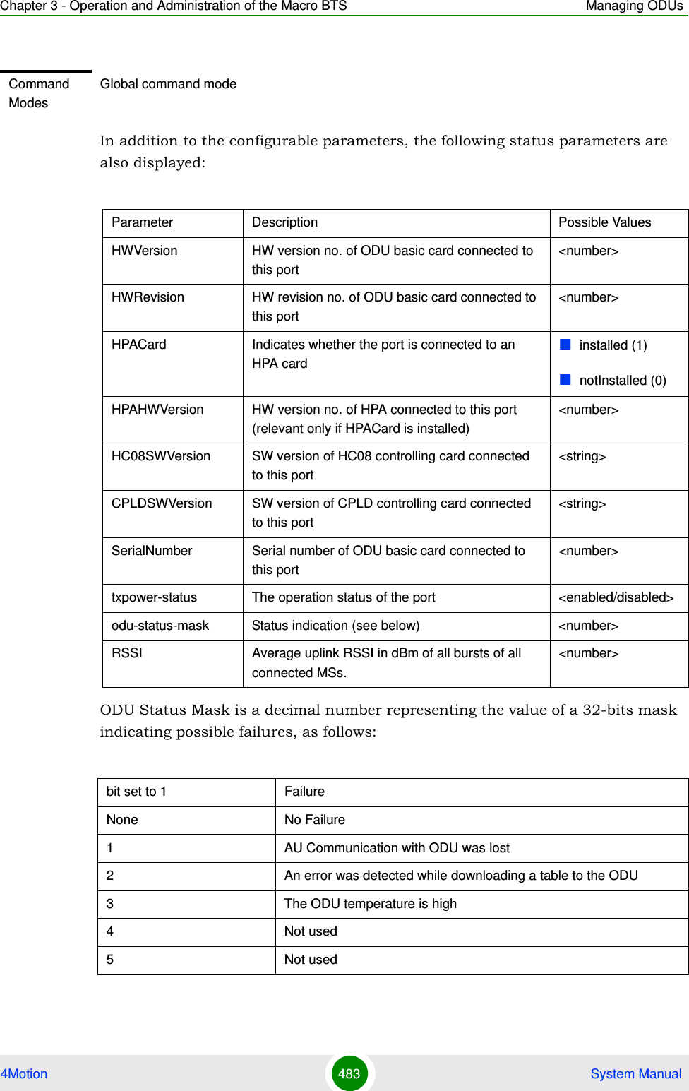
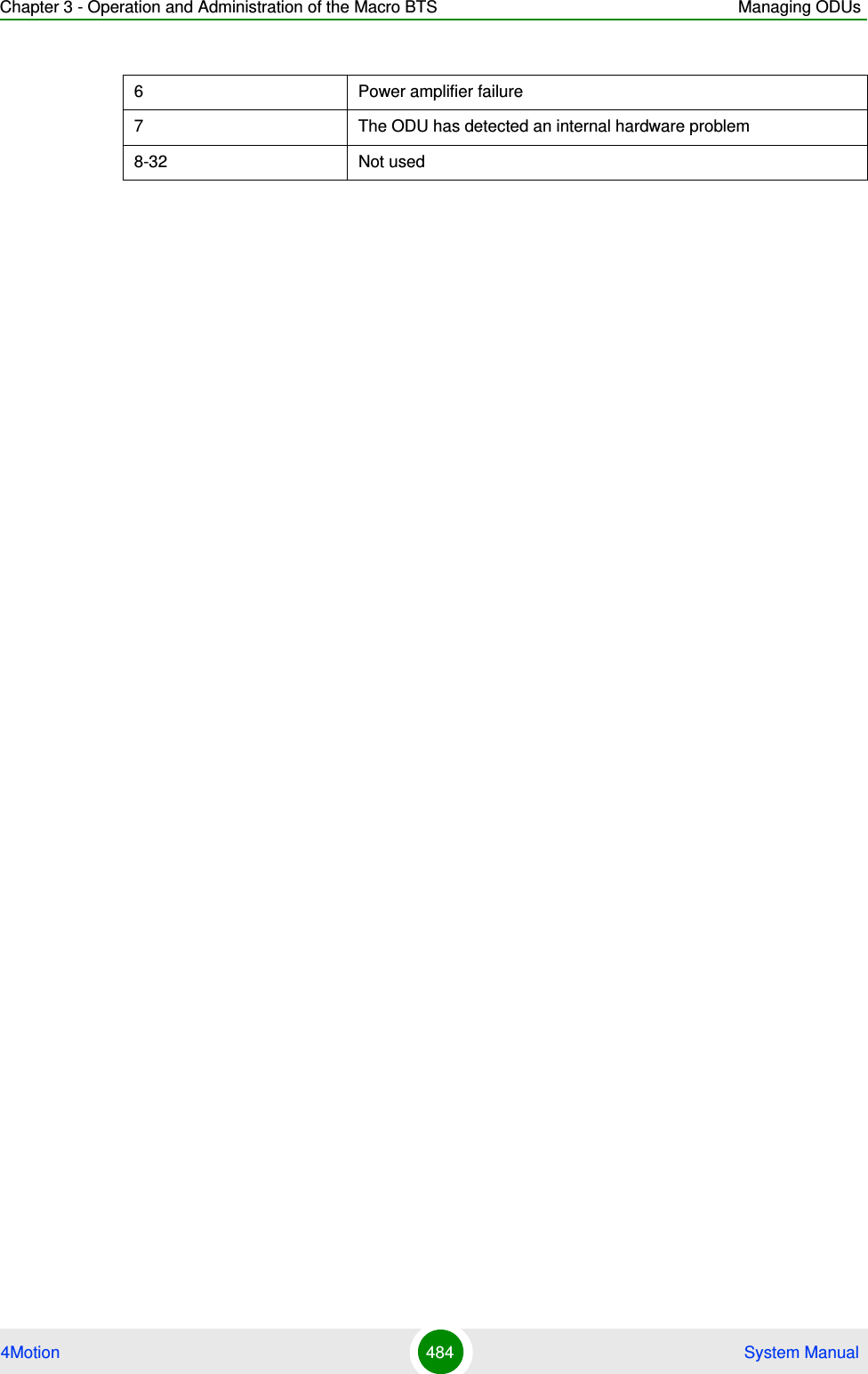
![Chapter 3 - Operation and Administration of the Macro BTS Managing ODUs4Motion 482 System ManualSyntax Description Parameter Description Presence Default ValuePossible Values[odu-no <(1 to 28 StepSize 1)> ]The number of the ODU Specify a value for this parameter if you want to display the parameters of a specific ODU Port. Do not specify a value for this parameter if you want to display the general parameters of all ODU Ports.Optional N/A 1-28[port-no <(1 to 4 StepSize 1)> ]The number of the Port Specify a value for this parameter if you want to display the parameters of a specific ODU Port. Do not specify a value for this parameter if you want to display the general parameters of all ODU Ports.Optional N/A 1-4Display Format(for each existing ODU Port if requested for all ODU Ports)ODUNo. :<value>ODUPortNo :<value>TxPower(dBm) :<value>TxEnable :<value>HWVersion :<value>HWRevision :<value>HPACard :<value>HPAHWVersion :<value>HC08SWVersion :<value>CPLDSWVersion :<value>SerialNumber :<value>txpower-status :<value>odu-status-mask :<value>RSSI :<value>](https://usermanual.wiki/Alvarion-Technologies/MICRO-25.Manual-p4/User-Guide-1329245-Page-84.png)
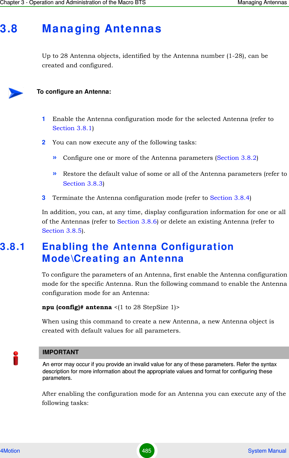
![Chapter 3 - Operation and Administration of the Macro BTS Managing Antennas4Motion 486 System ManualConfigure one or more of the parameters of the Antenna (refer to Section 3.8.2)Restore the default value of the non-mandatory parameters parameter (refer to Section 3.8.3)After executing the above tasks, you can terminate the Antenna configuration mode (refer to Section 3.8.4) and return to the global configuration mode.3.8 .2 Configuring Antenna Pa ra m e t e rsAfter enabling the Antenna configuration mode you can configure the Antenna parameters.To configure the Antenna parameters, run the following command:npu(config-antenna-1)# params [antenna-type <string (32)>] [no-of-ports <(1 to 8 StepSize 1)>] [mechanical-downtilt <(-90 to 90 StepSize 0.1)>] [electrical-downtilt <(-90 to 90 StepSize 0.1)>] [longitude <longitude>] [latitude <latitude>] [tower-height <(0 to 500 StepSize 1)>] [heading <(0 to 359 StepSize 1)>] [cable-loss <(0 to 20 StepSize 0.1)>] [antenna-product-id {<a list of default and standard antennas> } ]Command Syntaxnpu (config)# antenna <(1 to 28 StepSize 1)> Privilege Level10Syntax Description Parameter Description Presence Default ValuePossible Values<(1 to 28 StepSize 1)> The Antenna number Mandatory N/A 1-28Command ModesGlobal configuration modeNOTEThe following examples are for antenna-1 configuration mode.](https://usermanual.wiki/Alvarion-Technologies/MICRO-25.Manual-p4/User-Guide-1329245-Page-88.png)
![Chapter 3 - Operation and Administration of the Macro BTS Managing Antennas4Motion 487 System ManualNOTEThe no-of-ports parameter is not relevant since the number of ports is derived from the antenna-type.Command Syntaxnpu(config-antenna-1)# params [antenna-type <string (32)> ] [no-of-ports <(1 to 8 StepSize 1)> ] [mechanical-downtilt <(-90 to 90 StepSize 0.1)> ] [electrical-downtil <(-90 to 90 StepSize 0.1)> ] [longitude <longitude> ] [latitude <latitude> ] [tower-height <(0 to 500 StepSize 1)> ] [heading <(0 to 359 StepSize 1)> ] [cable-loss <(0 to 20StepSize 0.1)> ] [antenna-product-id {<a list of default and standard antennas>} ]Privilege Level10Syntax Description Parameter Description Presence Default ValuePossible Values[antenna-type <string (32)> ]Antenna type to be populated manually for inventory information onlyOptional N/A String (up to 32 printable characters)[no-of-ports <(1 to 8 StepSize 1)> ]The number of antenna ports. Not relevant since the number of ports is derived from the antenna-type.Optional 1 1-8[mechanical-downtilt <(-90 to 90 StepSize 0.1)> ]Downwards mechanical tilt of the antenna (in degrees) as opposed to the electrical tilt already integrated in the antenna (and thus taken as reference; instead of the horizontal plane)Optional 0 -90.0 to 90.0 in steps of 0.1[electrical-downtil <(-90 to 90 StepSize 0.1)> ]Downwards electrical tilt of the antenna, in degreesOptional 0 -90.0 to 90.0 in steps of 0.1](https://usermanual.wiki/Alvarion-Technologies/MICRO-25.Manual-p4/User-Guide-1329245-Page-89.png)
![Chapter 3 - Operation and Administration of the Macro BTS Managing Antennas4Motion 488 System Manual[longitude <longitude> ] The longitude of the antenna.The recommended format is lll.mmm.a where lll.mmm is the longitude in degrees (lll - between 000 and 179, mmm - between 000 and 999), a is E (East) or W (West).Optional 000.000;EString[latitude <latitude> ] The latitude of the antenna. The recommended format is lll.mmm.a where lll.mmm is the longitude in degrees (lll - between 000 and 89, mmm - between 000 and 999), a is N (North) or S (South).Optional 000.000;NString[tower-height <(0 to 500 StepSize 1)> ]Defines the height of the antenna above the ground in meters.Optional 0 0-500[heading <(0 to 359 StepSize 1)> ]Indicates the azimuth angle (in degrees) between the center of the horizontal antenna beamwidth and the true north; counting clockwise.Optional 0-359[cable-loss <(0 to 20 StepSize 0.1)> ]The attenuation (in dB) of the cable between the ODU port and antenna port (informative only)Optional 0.5 0-20 in steps of 0.1[antenna-product-id {<a list of default and standard antennas>} ]The product id of the antenna. All parameters required by the system are taken from a file that includes the parameters for all supported antennas.Optional Default2PortDSone of the options in the list of default and standard antennasCommand Modesantenna configuration mode](https://usermanual.wiki/Alvarion-Technologies/MICRO-25.Manual-p4/User-Guide-1329245-Page-90.png)
![Chapter 3 - Operation and Administration of the Macro BTS Managing Antennas4Motion 489 System Manual3.8 .3 Restoring Default Value s for Antenna Pa ra m e t e r sAfter enabling the Antenna configuration mode you can restore the default values for some or all of the parameters (excluding the mandatory heading parameter).To restore one or several Antenna parameters do their default value, run the following command:npu(config-antenna-1)# no params [antenna-type] [no-of-ports] [mechanical-downtilt] [electrical-downtil] [longitude] [latitude] [tower-height] [heading] [cable-loss] [antenna-product-id]You can restore one or several parameters to the default value(s) by specifying only those parameter. For example, to restore only the mechanical-downtilt and electrical-downtilt to their default values, run the following command:npu(config-antenna-1)# no params mechanical-downtilt electrical-downtilThe mechanical-downtilt and electrical-downtilt will be restored to their default values, while all other parameters will remain unchanged.To restore all parameters to their default value, run the following command:npu(config-antenna-1)# no paramsNOTEYou can display configuration information for the Antenna parameters. For details, refer to Section 3.8.6.IMPORTANTAn error may occur if you provide an invalid value for any of these parameters. Refer the syntax description for more information about the appropriate values and format for configuring these parameters.NOTERefer to Section 3.8.2 for a description and default values of these parameters.Command Syntaxnpu(config-antenna-1)# no params [antenna-type] [no-of-ports] [mechanical-downtilt] [electrical-downtil] [longitude] [latitude] [tower-height] [heading] [cable-loss] [antenna-product-id]](https://usermanual.wiki/Alvarion-Technologies/MICRO-25.Manual-p4/User-Guide-1329245-Page-91.png)
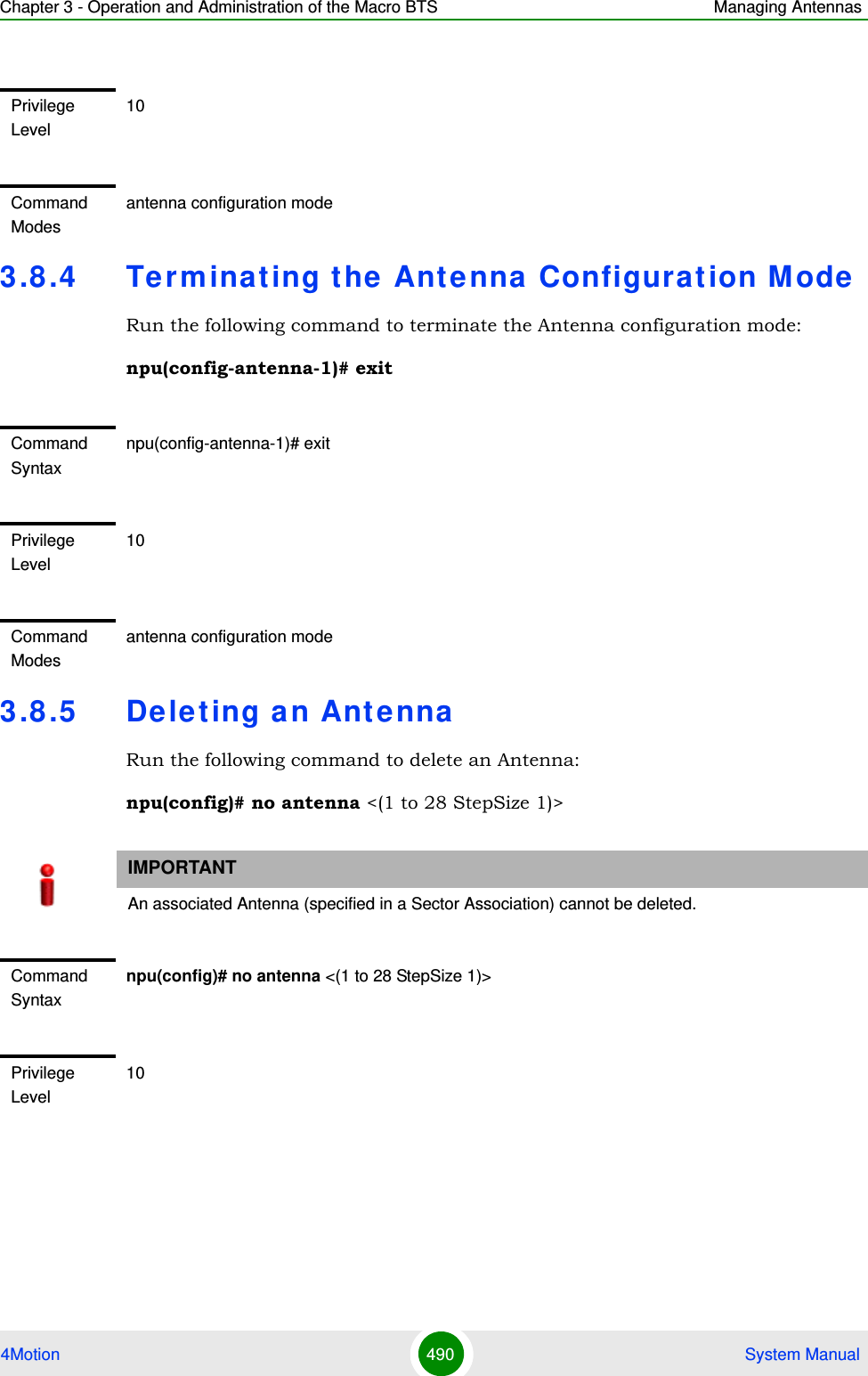
![Chapter 3 - Operation and Administration of the Macro BTS Managing Antennas4Motion 491 System Manual3.8 .6 Displa ying Configurat ion I nformation for AntennasTo display configuration information of a specific or all Antennas, run the following command: npu# show antenna [antenna-no <(1 to 28 StepSize 1)>]Specify the Antenna number (1-28) if you want to display configuration information for a particular Antenna. Do not specify values for this parameter if you want to view configuration information for all existing Antennas.Syntax Description Parameter Description Presence Default ValuePossible Values<(1 to 28 StepSize 1)> The Antenna number Mandatory N/A 1-28Command ModesGlobal configuration modeCommand Syntaxnpu# show antenna [antenna-no <(1 to 28 StepSize 1)>]Privilege Level1Syntax Description Parameter Description Presence Default ValuePossible Values[antenna-no <(1 to 28 StepSize 1)> ]The number of the Antenna Specify a value for this parameter if you want to display the parameters of a specific Antenna. Do not specify a value for this parameter if you want to display the parameters of all Antennas.Optional N/A 1-28](https://usermanual.wiki/Alvarion-Technologies/MICRO-25.Manual-p4/User-Guide-1329245-Page-93.png)
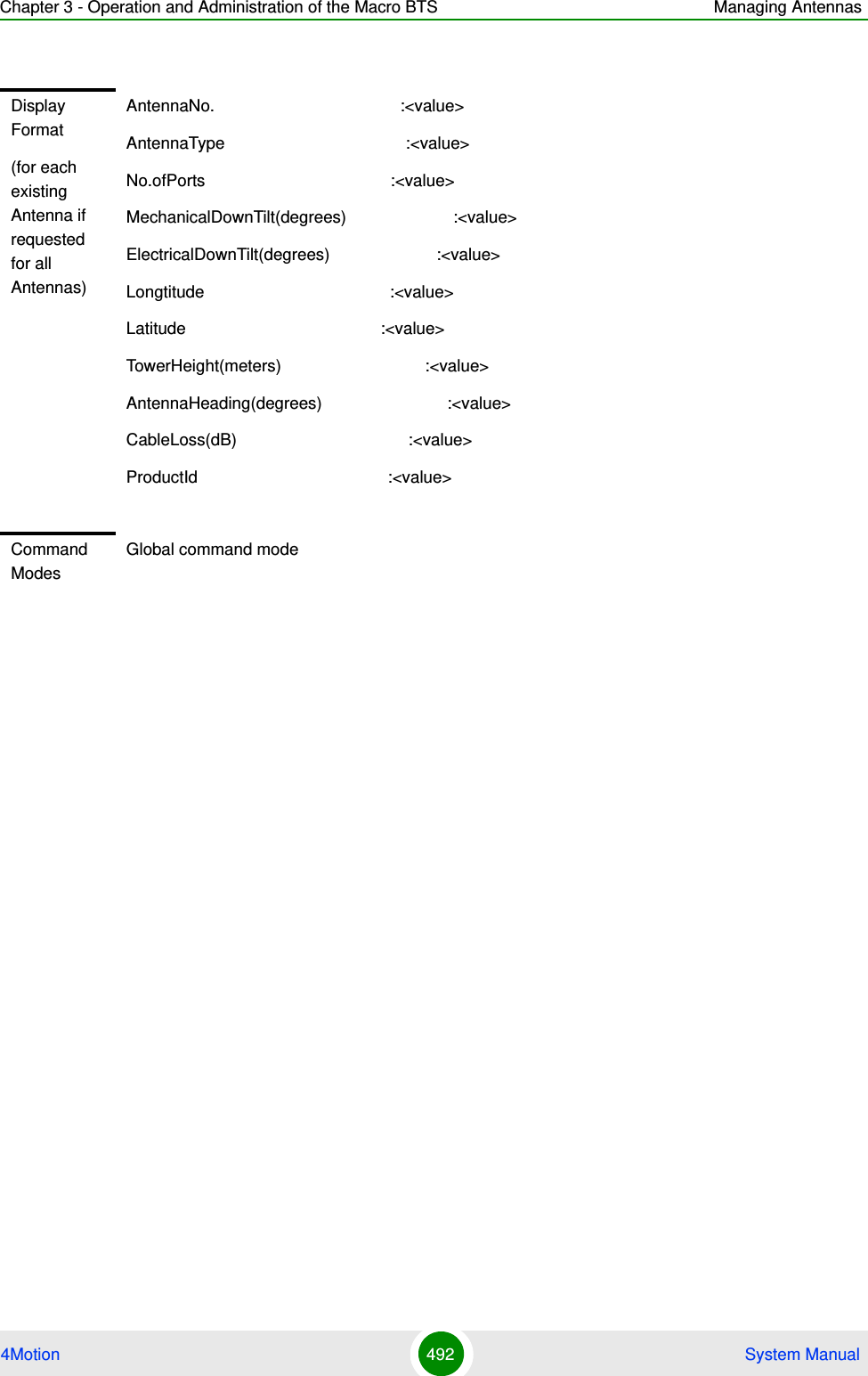
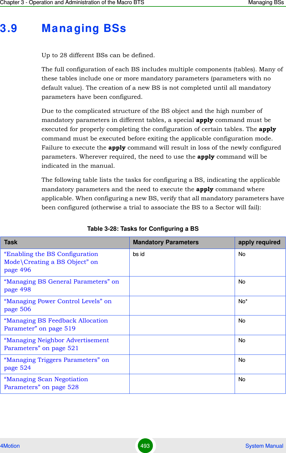
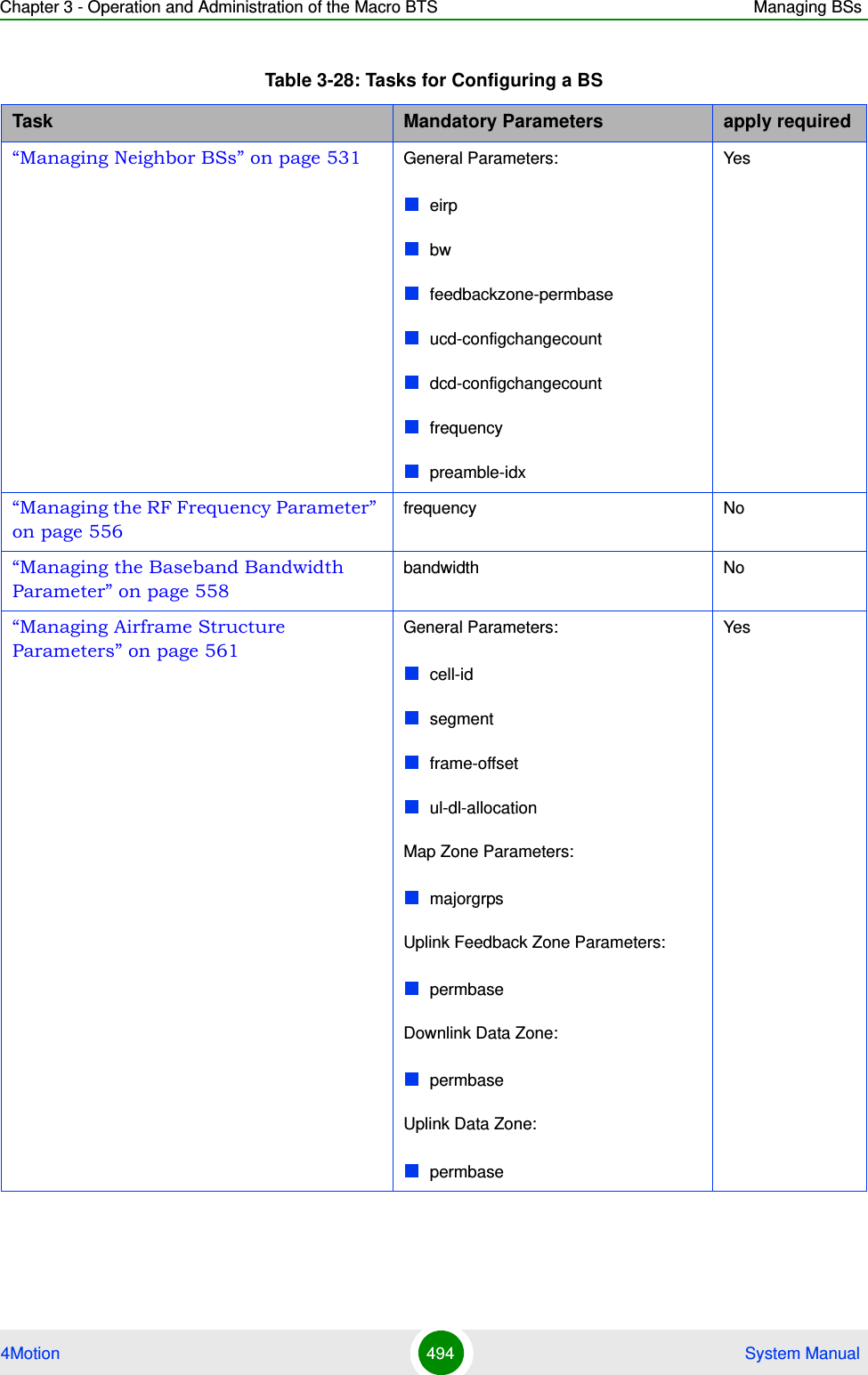
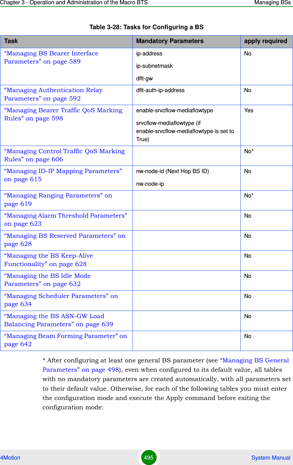
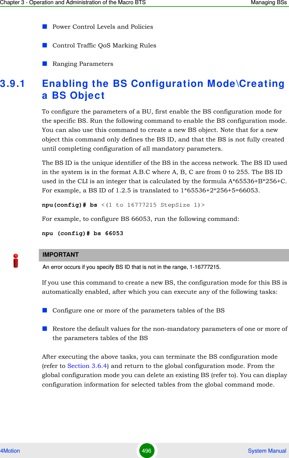
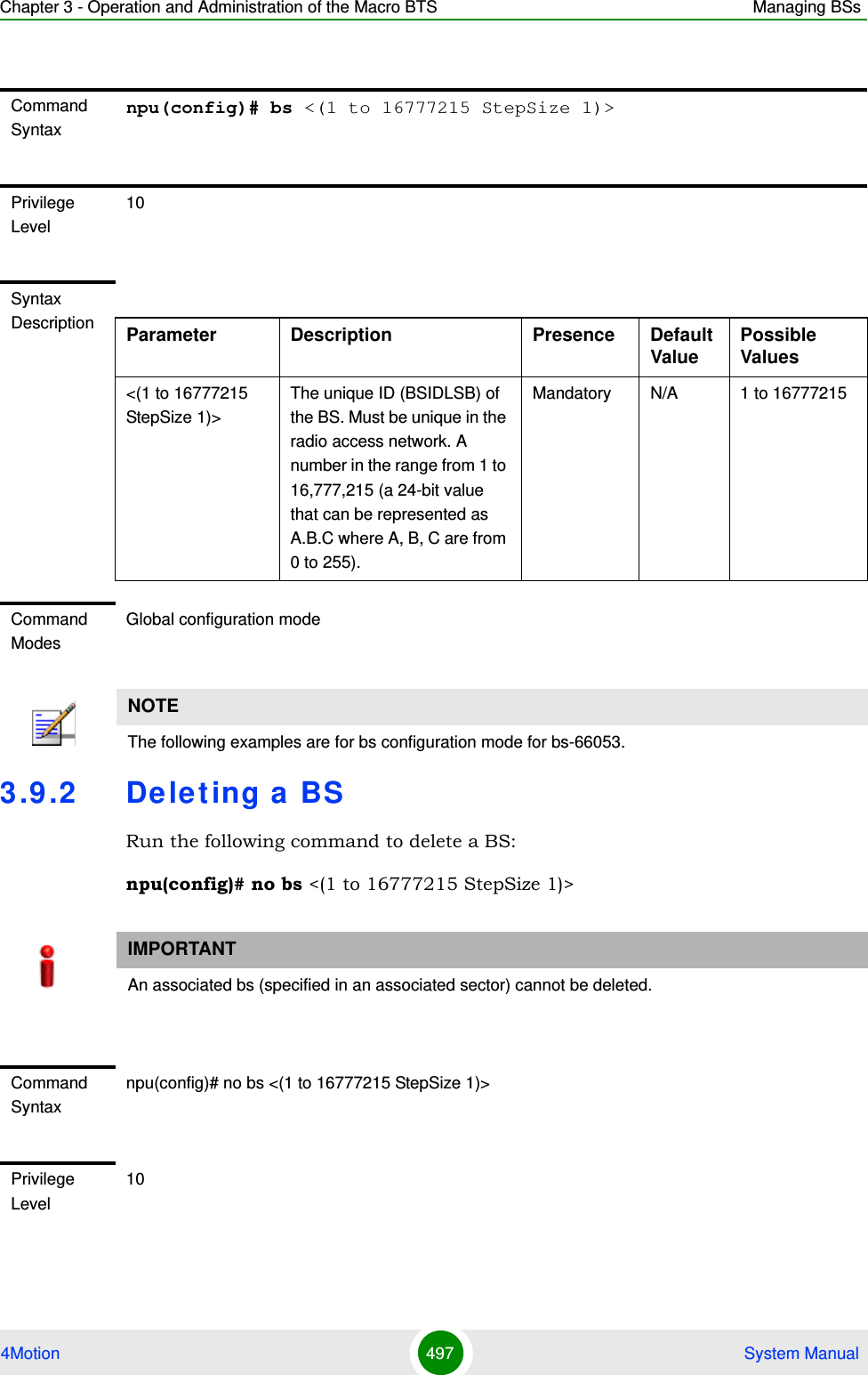
![Chapter 3 - Operation and Administration of the Macro BTS Managing BSs4Motion 498 System Manual3.9 .3 Ma na ging BS Ge neral ParametersThe general parameters of a BS include the Operator ID and the BS Name.After enabling the BS configuration mode, you can execute the following tasks:Configure one or more of the general parameters (refer to Section 3.9.3.1).Restore the default values of one or all of the general parameters (refer to Section 3.9.3.2).You can display configuration information for the general parameters of a selected or all existing BSs (refer to Section 3.9.3.3).3.9.3.1 Configuring BS General ParametersFrom the BS configuration mode, run the following command:npu(config-bs-66053)# general [operator-id <(1 to 16777215 StepSize 1)>] [bs-name <string (32)>] [ul-def-rate {ctcQpskOneOverTwoTimesSix | ctcQpskOneOverTwoTimesFour | ctcQpskOneOverTwoTimesTwo | ctcQpskOneOverTwo | ctcQpskThreeOverFour | ctcQamSixteenOneOverTwo | ctcQamSixteenThreeOverFour | ctcQamSixtyFourOneOverTwo | ctcQamSixtyFourTwoOverThree | ctcQamSixtyFourThreeOverFour | ctcQamSixtyFourFiveOverSix} ] [dl-def-rate-for-management {ctcQpskOneOverTwoTimesSix | ctcQpskOneOverTwoTimesFour | ctcQpskOneOverTwoTimesTwo | ctcQpskOneOverTwo | ctcQpskThreeOverFour | ctcQamSixteenOneOverTwo | ctcQamSixteenThreeOverFour | ctcQamSixtyFourOneOverTwo | ctcQamSixtyFourTwoOverThree | ctcQamSixtyFourThreeOverFour | Syntax Description Parameter Description Presence Default ValuePossible Values<(1 to 16777215 StepSize 1)>The unique ID (BSIDLSB) of the BS. Mandatory N/A 1 to 16777215Command ModesGlobal configuration modeTo configure the BS General Parameters:](https://usermanual.wiki/Alvarion-Technologies/MICRO-25.Manual-p4/User-Guide-1329245-Page-100.png)
![Chapter 3 - Operation and Administration of the Macro BTS Managing BSs4Motion 499 System ManualctcQamSixtyFourFiveOverSix} ] [dl-def-rate-for-data {ctcQpskOneOverTwoTimesSix | ctcQpskOneOverTwoTimesFour | ctcQpskOneOverTwoTimesTwo | ctcQpskOneOverTwo | ctcQpskThreeOverFour | ctcQamSixteenOneOverTwo | ctcQamSixteenThreeOverFour | ctcQamSixtyFourOneOverTwo | ctcQamSixtyFourTwoOverThree | ctcQamSixtyFourThreeOverFour | ctcQamSixtyFourFiveOverSix} ] [deployment {fix | mobile} ]NOTEAfter configuring at least one general BS parameter (see “Managing BS General Parameters” on page 555), even when configured to its default value, all tables with no mandatory parameters are created automatically, with all parameters set to their default value. Otherwise, for each of the following tables you must enter the configuration mode and execute the Apply command before exiting the configuration mode:Power Control Levels and PoliciesControl Traffic QoS Marking RulesRanging ParametersCommand Syntaxnpu(config-bs-66053)# general [operator-id <(1 to 16777215 StepSize 1)> ] [bs-name <string (32)> ] [ul-def-rate {ctcQpskOneOverTwoTimesSix | ctcQpskOneOverTwoTimesFour | ctcQpskOneOverTwoTimesTwo | ctcQpskOneOverTwo | ctcQpskThreeOverFour | ctcQamSixteenOneOverTwo | ctcQamSixteenThreeOverFour | ctcQamSixtyFourOneOverTwo | ctcQamSixtyFourTwoOverThree | ctcQamSixtyFourThreeOverFour | ctcQamSixtyFourFiveOverSix} ] [dl-def-rate-for-management {ctcQpskOneOverTwoTimesSix | ctcQpskOneOverTwoTimesFour | ctcQpskOneOverTwoTimesTwo | ctcQpskOneOverTwo | ctcQpskThreeOverFour | ctcQamSixteenOneOverTwo | ctcQamSixteenThreeOverFour | ctcQamSixtyFourOneOverTwo | ctcQamSixtyFourTwoOverThree | ctcQamSixtyFourThreeOverFour | ctcQamSixtyFourFiveOverSix} ] [dl-def-rate-for-data {ctcQpskOneOverTwoTimesSix | ctcQpskOneOverTwoTimesFour | ctcQpskOneOverTwoTimesTwo | ctcQpskOneOverTwo | ctcQpskThreeOverFour | ctcQamSixteenOneOverTwo | ctcQamSixteenThreeOverFour | ctcQamSixtyFourOneOverTwo | ctcQamSixtyFourTwoOverThree | ctcQamSixtyFourThreeOverFour | ctcQamSixtyFourFiveOverSix} ] [deployment {fix | mobile} ]](https://usermanual.wiki/Alvarion-Technologies/MICRO-25.Manual-p4/User-Guide-1329245-Page-101.png)
![Chapter 3 - Operation and Administration of the Macro BTS Managing BSs4Motion 500 System ManualPrivilege Level10Syntax Description Parameter Description Presence Default ValuePossible Values[operator-id <(1 to 16777215 StepSize 1)>]A unique operator identifier. The same Operator ID must be used throughout the radio access network. (a 24-bit value that can be represented as A.B.C where A, B, C are from 0 to 255)Optional 16773929 1 to 16777215[bs-name <string (32)>] BS name Optional empty stringA string of up to 32 printable characters.](https://usermanual.wiki/Alvarion-Technologies/MICRO-25.Manual-p4/User-Guide-1329245-Page-102.png)
![Chapter 3 - Operation and Administration of the Macro BTS Managing BSs4Motion 501 System Manual[ul-def-rate {ctcQpskOneOverTwoTimesSix | ctcQpskOneOverTwoTimesFour | ctcQpskOneOverTwoTimesTwo | ctcQpskOneOverTwo | ctcQpskThreeOverFour | ctcQamSixteenOneOverTwo | ctcQamSixteenThreeOverFour | ctcQamSixtyFourOneOverTwo | ctcQamSixtyFourTwoOverThree | ctcQamSixtyFourThreeOverFour | ctcQamSixtyFourFiveOverSix} ]The uplink basic rate. Optional ctcQpskOneOverTwoctcQpskOneOverTwoTimesSixctcQpskOneOverTwoTimesFourctcQpskOneOverTwoTimesTwoctcQpskOneOverTwoctcQpskThreeOverFourctcQamSixteenOneOverTwoctcQamSixteenThreeOverFourctcQamSixtyFourOneOverTwoctcQamSixtyFourTwoOverThreectcQamSixtyFourThreeOverFourctcQamSixtyFourFiveOverSix}](https://usermanual.wiki/Alvarion-Technologies/MICRO-25.Manual-p4/User-Guide-1329245-Page-103.png)
![Chapter 3 - Operation and Administration of the Macro BTS Managing BSs4Motion 502 System Manual[dl-def-rate-for-management {ctcQpskOneOverTwoTimesSix | ctcQpskOneOverTwoTimesFour | ctcQpskOneOverTwoTimesTwo | ctcQpskOneOverTwo | ctcQpskThreeOverFour | ctcQamSixteenOneOverTwo | ctcQamSixteenThreeOverFour | ctcQamSixtyFourOneOverTwo | ctcQamSixtyFourTwoOverThree | ctcQamSixtyFourThreeOverFour | ctcQamSixtyFourFiveOverSix} ]The downlink basic rate for unicast and broadcast management.Optional ctcQpskOneOverTwoctcQpskOneOverTwoTimesSixctcQpskOneOverTwoTimesFourctcQpskOneOverTwoTimesTwoctcQpskOneOverTwoctcQpskThreeOverFourctcQamSixteenOneOverTwoctcQamSixteenThreeOverFourctcQamSixtyFourOneOverTwoctcQamSixtyFourTwoOverThreectcQamSixtyFourThreeOverFourctcQamSixtyFourFiveOverSix}](https://usermanual.wiki/Alvarion-Technologies/MICRO-25.Manual-p4/User-Guide-1329245-Page-104.png)
![Chapter 3 - Operation and Administration of the Macro BTS Managing BSs4Motion 503 System Manual[dl-def-rate-for-data {ctcQpskOneOverTwoTimesSix | ctcQpskOneOverTwoTimesFour | ctcQpskOneOverTwoTimesTwo | ctcQpskOneOverTwo | ctcQpskThreeOverFour | ctcQamSixteenOneOverTwo | ctcQamSixteenThreeOverFour | ctcQamSixtyFourOneOverTwo | ctcQamSixtyFourTwoOverThree | ctcQamSixtyFourThreeOverFour | ctcQamSixtyFourFiveOverSix} ]The downlink basic rate for data.Optional ctcQpskOneOverTwoctcQpskOneOverTwoTimesSixctcQpskOneOverTwoTimesFourctcQpskOneOverTwoTimesTwoctcQpskOneOverTwoctcQpskThreeOverFourctcQamSixteenOneOverTwoctcQamSixteenThreeOverFourctcQamSixtyFourOneOverTwoctcQamSixtyFourTwoOverThreectcQamSixtyFourThreeOverFourctcQamSixtyFourFiveOverSix}[deployment {fix | mobile} ]The type of deployment in the area served by the BS. To support proper handover, should be set to fix only if mobile MSs are not expected.Optional fix fixmobileCommand Modesbs configuration mode](https://usermanual.wiki/Alvarion-Technologies/MICRO-25.Manual-p4/User-Guide-1329245-Page-105.png)
![Chapter 3 - Operation and Administration of the Macro BTS Managing BSs4Motion 504 System Manual3.9.3.2 Restoring Default Values for BS General ParametersAfter enabling the BS configuration mode you can restore the default values for one or all of the general BS parameters.To restore one or all general BS parameters do their default value, run the following command:npu(config-bs-66053)# no general [operator-id] [bs-name] [ul-def-rate-for-management] [dl-def-rate] [dl-def-rate-for-data] [deployment]You can restore one parameter to its default value by specifying only that parameter. For example, to restore only the operator-id to its default value, run the following command:npu(config-bs-66053)# no general operator-idThe operator-id will be restored to its default value, while the other parameters will remain unchanged.To restore all parameters to their default value, run the following command:npu(config-bs-66053)# no general3.9.3.3 Displaying Configuration Information for BS General ParametersTo display configuration information of the general parameters of a specific or all BSs, run the following command:NOTERefer to Section 3.9.3.1 for a description and default values of these parameters.Command Syntaxnpu(config-bs-66053)# no general [operator-id] [bs-name] [ul-def-rate] [dl-def-rate-for-management] [dl-def-rate-for-data] [deployment]Privilege Level10Command Modesbs configuration mode](https://usermanual.wiki/Alvarion-Technologies/MICRO-25.Manual-p4/User-Guide-1329245-Page-106.png)
![Chapter 3 - Operation and Administration of the Macro BTS Managing BSs4Motion 505 System Manualnpu# show general bs [<(1 to 16777215 StepSize 1)>]Specify the BS ID (1-16777215) of an existing BS if you want to display configuration information for a particular BS. Do not specify values for this parameter if you want to view configuration information for all existing BSs.Command Syntaxnpu# show general bs [<(1 to 16777215 StepSize 1)> ]Privilege Level1Syntax Description Parameter Description Presence Default ValuePossible Values[<(1 to 16777215 StepSize 1)> ]The BS ID Specify a value for this parameter if you want to display the general parameters of a specific BS. Do not specify a value for this parameter if you want to display the general parameters of all BSs.Optional N/A 1-16777215Display Format(for each existing BS if requested for all BSs)BSIDLSB :<value>OperatorID :<value>BSName :<value>Defaultuplinkbasicrate :<value>Defaultdownlinkbasicrateformanagement :<value>Defaultdownlinkbasicratefordata :<value>Deployment :<value> Command ModesGlobal command mode](https://usermanual.wiki/Alvarion-Technologies/MICRO-25.Manual-p4/User-Guide-1329245-Page-107.png)
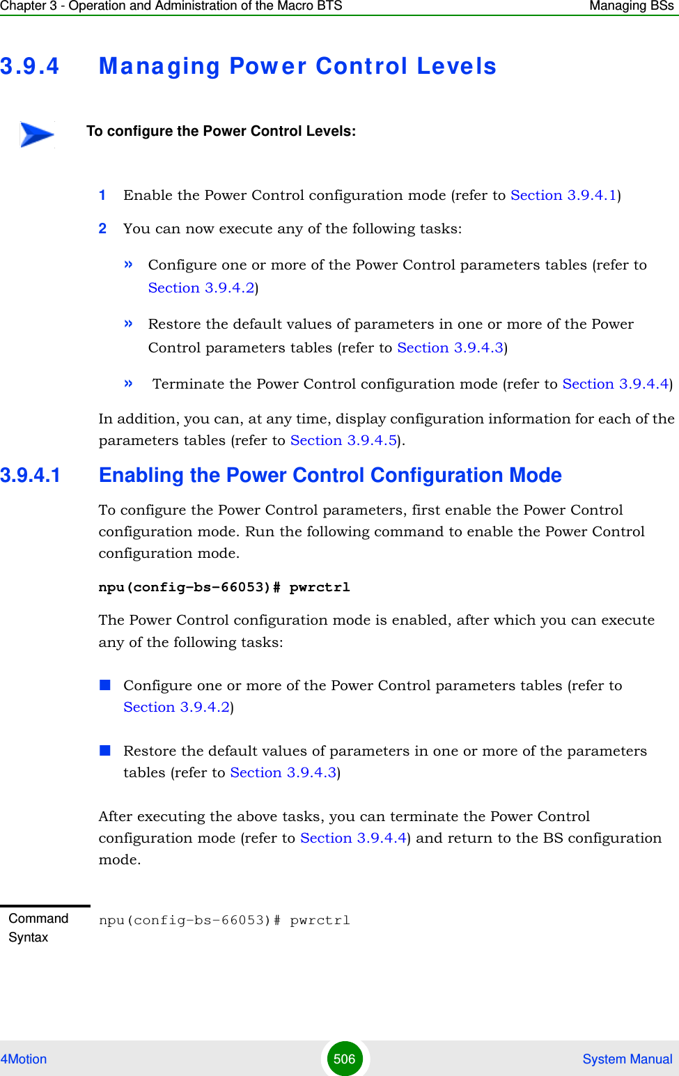
![Chapter 3 - Operation and Administration of the Macro BTS Managing BSs4Motion 507 System Manual3.9.4.2 Configuring Power Control ParametersAfter enabling the Power Control configuration mode you can configure the following parameters tables:Target Noise and Interference Level (refer to Section 3.9.4.2.1)Required C/N Level (refer to Section 3.9.4.2.2)3.9.4.2.1 Configuring Power Control Target Noise and Interference Level ParametersThe Target Noise and Interference Level table enables defining the target limits for various noise and interference levels.To configure the Target Noise and Interference Levels, run the following command:npu(config-bs-66053-pwrctrl)# nilevels [target-ni <(-130 to -110 StepSize 1)>] [allowed-if-level {veryHigh | high | medium | low} ]]Privilege Level10Command Modesbs configuration modeNOTEIn the current release, the command for configuring Maximum EIRxP parameter, npu(config-bs-66053-pwrctrl)# maxeirxp, is not applicable and should not be used. An attempt to configure a value using this command will be ignored (value is taken from vendor file).NOTEAn attempt to configure the cqi-ack-ranging parameter will be ignored. The value of this parameter is set by internal logic.Command Syntaxnpu(config-bs-66053-pwrctrl)# nilevels [target-ni <(-130 to -110 StepSize 1)> ] [allowed-if-level {veryHigh | high | medium | low} ]Privilege Level10](https://usermanual.wiki/Alvarion-Technologies/MICRO-25.Manual-p4/User-Guide-1329245-Page-109.png)
![Chapter 3 - Operation and Administration of the Macro BTS Managing BSs4Motion 508 System Manual3.9.4.2.2 Configuring the Power Control Required C/N Level ParametersThe Required C/N Levels table enables defining the Carrier to Noise Ratios required for various types of transmissions.To configure the Required C/N Levels, run the following command:npu(config-bs-66053-pwrctrl)# requiredcnr [ack <(-20 to 50 StepSize 1)>] [cqi <(-20 to 50 StepSize 1)>] [cdma <(-20 to 50 StepSize 1)>] [qpsk-1by2 <(-20 to 50 StepSize 1)>] [qpsk-3by4 <(-20 to 50 StepSize 1)>] [qam16-1by2 <(-20 to 50 StepSize 1)>] [qam16-3by4 <(-20 to 50 StepSize 1)>] [qam64-1by2 <(-20 to 50 StepSize 1)>] [qam64-2by3 <(-20 to 50 StepSize 1)>] [qam64-3by4 <(-20 to 50 StepSize 1)>] [qam64-5by6 <(-20 to 50 StepSize 1)>]Syntax Description Parameter Description Presence Default ValuePossible Values[target-ni <(-130 to -110 StepSize 1)> ]Target Noise and interference level for the PUSC zone, in dBm.Optional -127 -130 to -110 in steps of 1[allowed-if-level {veryHigh | high | medium | low} ]Allowed Interference Level: Correction of maximum allowed UL MCS based on measured DL CINR.Optional high veryHighhighmediumlowCommand Modesbs power control configuration mode Command Syntaxnpu(config-bs-66053-pwrctrl)# requiredcnr [ack <(-20 to 50 StepSize 1)> ] [cqi <(-20 to 50 StepSize 1)> ] [cdma <(-20 to 50 StepSize 1)> ] [qpsk-1by2 <(-20 to 50 StepSize 1)> ] [qpsk-3by4 <(-20 to 50 StepSize 1)> ] [qam16-1by2 <(-20 to 50 StepSize 1)> ] [qam16-3by4 <(-20 to 50 StepSize 1)> ] [qam64-1by2 <(-20 to 50 StepSize 1)> ] [qam64-2by3 <(-20 to 50 StepSize 1)> ] [qam64-3by4 <(-20 to 50 StepSize 1)> ] [qam64-5by6 <(-20 to 50 StepSize 1)> ]Privilege Level10](https://usermanual.wiki/Alvarion-Technologies/MICRO-25.Manual-p4/User-Guide-1329245-Page-110.png)
![Chapter 3 - Operation and Administration of the Macro BTS Managing BSs4Motion 509 System ManualSyntax Description Parameter Description Presence Default ValuePossible Values[ack <(-20 to 50 StepSize 1)> ]The C/N in dB required for sending ACK, reported to the MS for power control purposes.Optional 7 -20 to 50[cqi <(-20 to 50 StepSize 1)> ]The C/N in dB required for sending CQI, reported to the MS for power control purposes.Must be in the range from requiredcnr-ack - 8 to requiredcnr-ack + 7 (see ack parameter above)Optional 12 -20 to 50 [cdma <(-20 to 50 StepSize 1)> ]The C/N in dB required for transmitting CDMA, reported to the MS for power control purposes.Must be in the range from requiredcnr-cqi - 8 to requiredcnr-cqi + 7 (see cqi parameter above)Optional 9 -20 to 50[qpsk-1by2 <(-20 to 50 StepSize 1)> ]The C/N in dB required for transmitting using QPSK 1/2, reported to the MS for power control purposes.Must be in the range from requiredcnr-cdma - 16 to requiredcnr-cdma + 14 (see cdma parameter above)Optional 13 -20 to 50[qpsk-3by4<(-20 to 50 StepSize 1)> ]The C/N in dB required for transmitting using QPSK 3/4, reported to the MS for power control purposes.Must be in the range from requiredcnr-qpsk-1by2 - 16 to requiredcnr-qpsk-1by2 + 14 (see qpsk-1by2 parameter above)Optional 16 -20 to 50](https://usermanual.wiki/Alvarion-Technologies/MICRO-25.Manual-p4/User-Guide-1329245-Page-111.png)
![Chapter 3 - Operation and Administration of the Macro BTS Managing BSs4Motion 510 System Manual[qam16-1by2 <(-20 to 50 StepSize 1)> ]The C/N in dB required for transmitting using 16QAM 1/2, reported to the MS for power control purposes.Must be in the range from requiredcnr-qpsk-3by4 - 8 to requiredcnr-qpsk-3by4 + 7 (see qpsk-3by4 parameter above)Optional 19 -20 to 50[qam16-3by4 <(-20 to 50 StepSize 1)> ]The C/N in dB required for transmitting using 16QAM 3/4, reported to the MS for power control purposes.Must be in the range from requiredcnr-qam16-1by2 - 16 to requiredcnr-qam16-1by2 + 14 (see qam16-1by2 parameter above)Optional 22 -20 to 50[qam64-1by2 <(-20 to 50 StepSize 1)> ]The C/N in dB required for transmitting using 64QAM 1/2, reported to the MS for power control purposes.Must be in the range from requiredcnr-qam16-3by4 - 16 to requiredcnr-qam16-3by4 + 14 (see qam16-3by4 parameter above)Optional 23 -20 to 50[qam64-2by3 <(-20 to 50 StepSize 1)> ]The C/N in dB required for transmitting using 64QAM 2/3, reported to the MS for power control purposes.Must be in the range from requiredcnr-qam64-1by2 - 8 to requiredcnr-qam64-1by2 + 7 (see qam64-1by2 parameter above)Optional 25 -20 to 50[qam64-3by4 <(-20 to 50 StepSize 1)> ]The C/N in dB required for transmitting using 64QAM 3/4, reported to the MS for power control purposes.Must be in the range from requiredcnr-qam64-2by3 - 8 to requiredcnr-qam54-2by3 + 7 (see qam54-2by3 parameter above)Optional 26 -20 to 50](https://usermanual.wiki/Alvarion-Technologies/MICRO-25.Manual-p4/User-Guide-1329245-Page-112.png)
![Chapter 3 - Operation and Administration of the Macro BTS Managing BSs4Motion 511 System Manual3.9.4.3 Restoring Default Values for Power Control Configuration ParametersAfter enabling the Power Control configuration mode you can restore the default values for parameters in the following parameters tables:Noise and Interference Level (refer to Section 3.9.4.3.1)Required C/N Level (refer to Section 3.9.4.3.2)3.9.4.3.1 Restoring the Default Values of Power Control Target Noise and Interference Level ParametersTo restore one or all of the Target Noise and Interference Level parameters to their default values, run the following command:npu(config-bs-66053-pwrctrl)# no nilevels [target-ni] [allowed-if-level]You can restore only one parameter to its default values by specifying only that parameter. For example, to restore only the target-ni to the default value, run the following command:npu(config-bs-66053-pwrctrl)# no nilevels target-niThe parameter will be restored to its default value, while the other parameter will remain unchanged.[qam64-5by6 <(-20 to 50 StepSize 1)> ]he C/N in dB required for transmitting using 64QAM 5/6, reported to the MS for power control purposes.Must be in the range from requiredcnr-qam64-3by4 - 8 to requiredcnr-qam64-3by4 + 7 (see qam64-3by4 parameter above)Optional 28 -20 to 50Command Modesbs power control configuration mode NOTEIn the current release, the command for restoring the default value for the Maximum EIRxP parameter, npu(config-bs-66053-pwrctrl)# no maxeirxp, is not applicable and should not be used. An attempt to restore the value to a default value using this command will be ignored (value is taken from vendor file).](https://usermanual.wiki/Alvarion-Technologies/MICRO-25.Manual-p4/User-Guide-1329245-Page-113.png)
![Chapter 3 - Operation and Administration of the Macro BTS Managing BSs4Motion 512 System ManualTo restore all Target Noise and Interference Level parameters to their default value, run the following command:npu(config-bs-66053-pwrctrl)# no nilevels3.9.4.3.2 Restoring the Default Values of Power Control Required C/N Level ParametersTo restore some or all of the Required C/N Levels parameters to their default values, run the following command:npu(config-bs-66053-pwrctrl)# no requiredcnr [ack] [cqi] [cdma] [qpsk-1by2] [qpsk-3by4] [qam16-1by2] [qam16-3by4] [qam64-1by2] [qam64-2by3] [qam64-3by4] [qam64-5by6]You can restore only some parameters to their default values by specifying only those parameter. For example, to restore only the ack and cqi parameters to the default values, run the following command:npu(config-bs-66053-pwrctrl)# no requiredcnr ack cqiThese parameters will be restored to their default value, while the other parameters will remain unchanged.To restore all Required C/N Levels parameters to their default value, run the following command:npu(config-bs-66053-pwrctrl)# no requiredcnrNOTERefer to Section 3.9.4.2.1 for a description and default values of these parameters.Command Syntaxnpu(config-bs-66053-pwrctrl)# no nilevels [target-ni] [allowed-if-level]Privilege Level10Command Modesbs power control configuration modeNOTERefer to Section 3.9.4.2.2 for a description and default values of these parameters.](https://usermanual.wiki/Alvarion-Technologies/MICRO-25.Manual-p4/User-Guide-1329245-Page-114.png)
![Chapter 3 - Operation and Administration of the Macro BTS Managing BSs4Motion 513 System Manual3.9.4.4 Terminating the Power Control Configuration ModeRun the following command to terminate the Power Control configuration mode:npu(config-bs-66053-pwrctrl)# exit3.9.4.5 Displaying Configuration Information for Power Control ParametersYou can display the current configuration information for the following parameters tables:Noise and Interference Level (refer to Section 3.9.4.5.1)Maximum EIRxP (refer to Section 3.9.4.5.2)Required C/N Level (refer to Section 3.9.4.5.3)All (refer to Section 3.9.4.5.4)Command Syntaxnpu(config-bs-66053-pwrctrl)# no requiredcnr [ack ] [cqi ] [cdma ] [qpsk-1by2 ] [qpsk-3by4 ] [qam16-1by2 ] [qam16-3by4 ] [qam64-1by2 ] [qam64-2by3 ] [qam64-3by4 ] [qam64-5by6 ]Privilege Level10Command Modesbs power control configuration modeCommand Syntaxnpu(config-bs-66053-pwrctrl)# exitPrivilege Level10Command Modesbs power control configuration mode](https://usermanual.wiki/Alvarion-Technologies/MICRO-25.Manual-p4/User-Guide-1329245-Page-115.png)
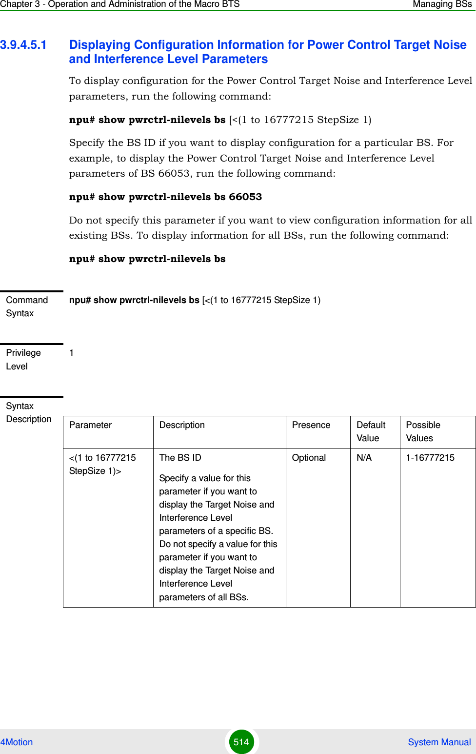
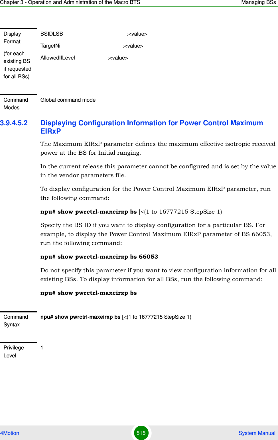
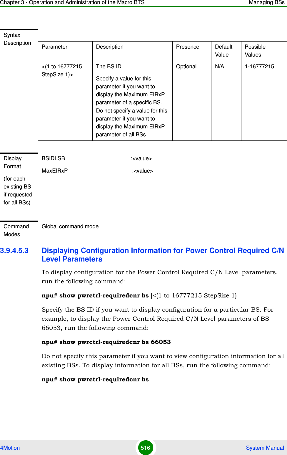
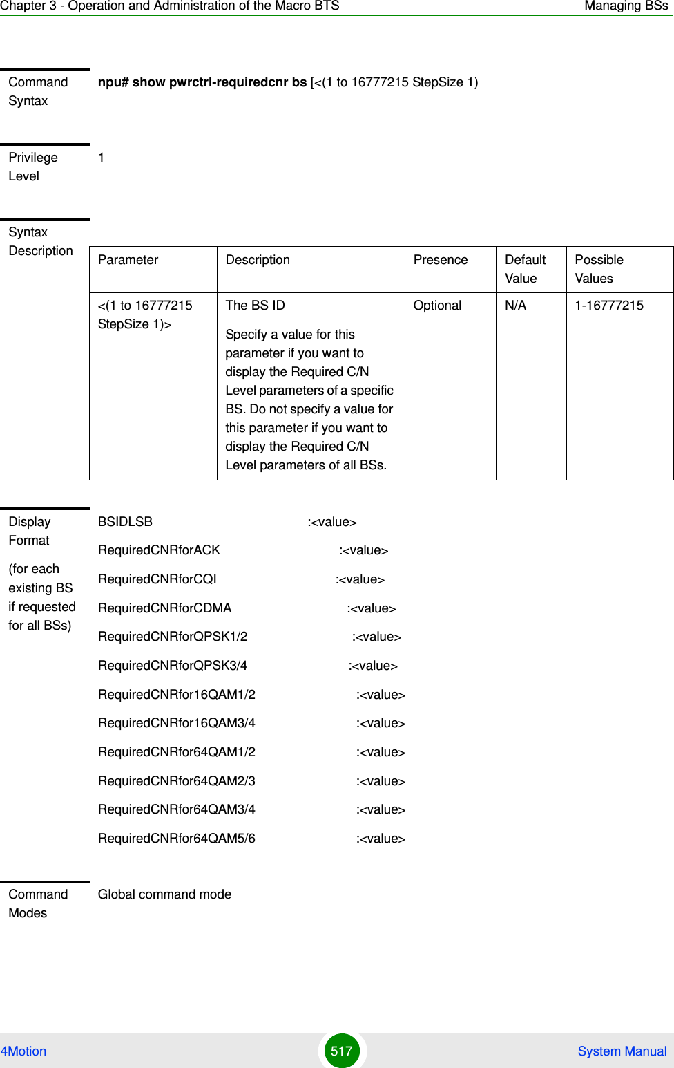
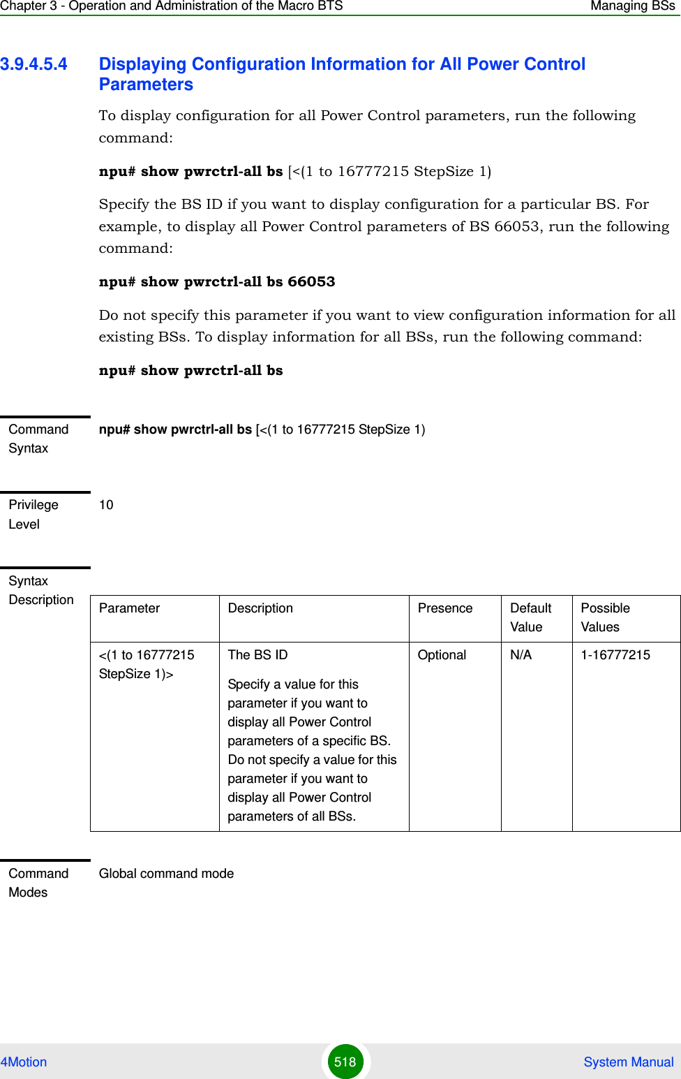
![Chapter 3 - Operation and Administration of the Macro BTS Managing BSs4Motion 519 System Manual3.9 .5 Ma na ging BS Feedback Allocation ParameterAfter enabling the BS configuration mode, you can execute the following tasks:Configure the Feedback Allocation parameter (refer to Section 3.9.5.1).Restore the default values of the Feedback Allocation parameter (refer to Section 3.9.5.2).You can display configuration information for the Feedback Allocation parameter of a selected or all existing BSs (refer to Section 3.9.5.3).3.9.5.1 Configuring Feedback Allocation ParameterFrom the BS configuration mode, run the following command:npu(config-bs-66053)# feedbackalloc [ir-cdma <(1 to 1 StepSize 1) | (2 to 2 StepSize 1) | (4 to 4 StepSize 1) | (6 to 6 StepSize 1) | (8 to 8 StepSize 1) | (10 to 10 StepSize 1)> ]To configure the Feedback Allocation Parameter:Command Syntaxnpu(config-bs-66053)# feedbackalloc [ir-cdma <(1 to 1 StepSize 1) | (2 to 2 StepSize 1) | (4 to 4 StepSize 1) | (6 to 6 StepSize 1) | (8 to 8 StepSize 1) | (10 to 10 StepSize 1)> ]Privilege Level10Syntax Description Parameter Description Presence Default ValuePossible Values[ir-cdma <<(1 to 1 StepSize 1) | (2 to 2 StepSize 1) | (4 to 4 StepSize 1) | (6 to 6 StepSize 1) | (8 to 8 StepSize 1) | (10 to 10 StepSize 1)>> ]The period of IR CDMA allocations, in frames.In the current release the actual value is always 2, regardless of the configured value.Optional 2 1, 2, 4, 6, 8, 10.](https://usermanual.wiki/Alvarion-Technologies/MICRO-25.Manual-p4/User-Guide-1329245-Page-121.png)
![Chapter 3 - Operation and Administration of the Macro BTS Managing BSs4Motion 520 System Manual3.9.5.2 Restoring the Default Values of the Feedback Allocation ParameterTo restore the ir-cdma non-mandatory parameter to the default values, run the following command:npu(config-bs-66053)# no feedbackalloc [ir-cdma] To restore the ir-cdma parameter to the default value, run any of the following commands:npu(config-bs-66053)# no feedbackalloc ir-cdmanpu(config-bs-66053)# no feedbackalloc3.9.5.3 Displaying Configuration Information for the Feedback Allocation ParameterTo display configuration information for Feedback Allocation parameter, run the following command:npu# show feedbackalloc bs [<(1 to 16777215 StepSize 1)Specify the BS ID if you want to display configuration for a particular BS. For example, to display the Feedback Allocation parameter of BS 66053, run the following command:npu# show feedbackalloc bs 66053Command Modesbs configuration modeNOTERefer to Section 3.9.5.1 for a description and default values of this parameter.Command Syntaxnpu(config-bs-66053)# no feedbackalloc [ir-cdma ]Privilege Level10Command Modesbs configuration mode](https://usermanual.wiki/Alvarion-Technologies/MICRO-25.Manual-p4/User-Guide-1329245-Page-122.png)
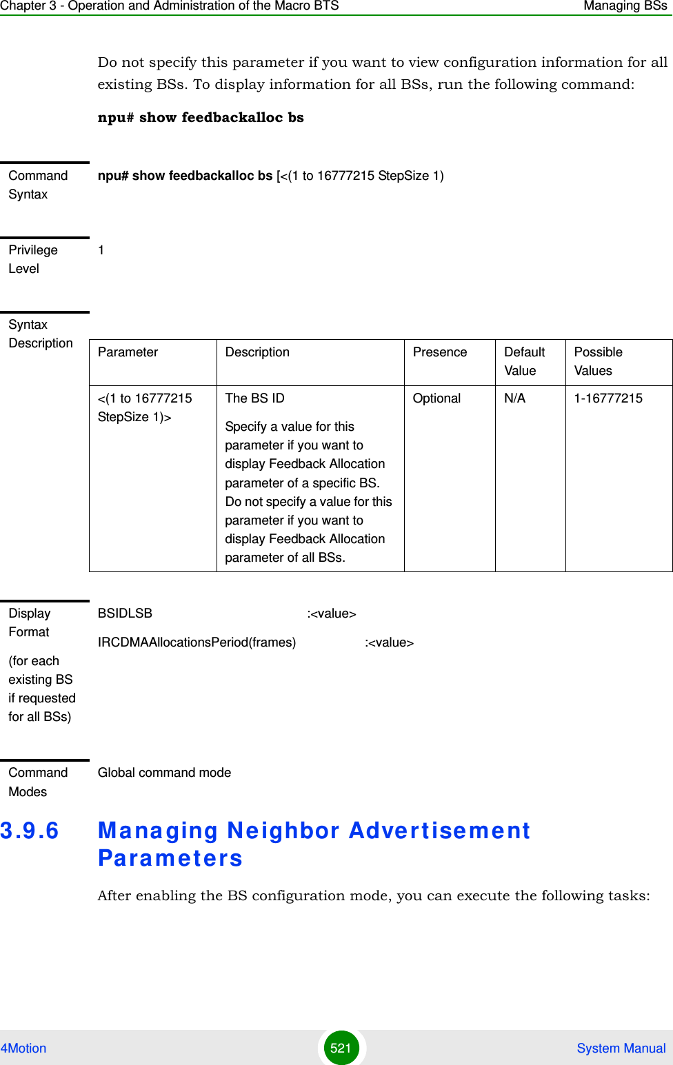
![Chapter 3 - Operation and Administration of the Macro BTS Managing BSs4Motion 522 System ManualConfigure one or more of the Neighbor Advertisement parameters (refer to Section 3.9.6.1).Restore the default values of one or all of the Neighbor Advertisement parameters (refer to Section 3.9.6.2).You can display configuration information for the Neighbor Advertisement parameters of a selected or all existing BSs (refer to Section 3.9.6.3).3.9.6.1 Configuring Neighbor Advertisement ParametersFrom the BS configuration mode, run the following command:npu(config-bs-66053)# nbradvertise [triggersetup <(0 to 100 StepSize 0.1)>]3.9.6.2 Restoring the Default Values of Neighbor Advertisement ParameterSince there is only one Neighbor Advertisement parameter, run any of the following commands to restore it to the default value:npu(config-bs-66053)# no nbradvertiseTo configure the Neighbor Advertisement Parameters:Command Syntaxnpu(config-bs-66053)# nbradvertise [triggersetup <(0 to 100 StepSize 0.1)> ]Privilege Level10Syntax Description Parameter Description Presence Default ValuePossible Values[triggersetup <(0 to 100 StepSize 0.1)> ]The periodic NBRADV transmission interval, in secondsOptional 10 0 - 100 in steps of 0.1Command Modesbs configuration mode](https://usermanual.wiki/Alvarion-Technologies/MICRO-25.Manual-p4/User-Guide-1329245-Page-124.png)
![Chapter 3 - Operation and Administration of the Macro BTS Managing BSs4Motion 523 System Manualnpu(config-bs-66053)# no nbradvertise triggersetup3.9.6.3 Displaying Configuration Information for Neighbor Advertisement ParametersTo display configuration information for the Neighbor Advertisement parameter, run the following command:npu# show nbradvertise bs [<(1 to 16777215 StepSize 1)Specify the BS ID if you want to display configuration for a particular BS. For example, to display the Neighbor Advertisement parameters of BS 66053, run the following command:npu# show nbradvertise bs 66053Do not specify this parameter if you want to view configuration information for all existing BSs. To display information for all BSs, run the following command:npu# show nbradvertise bsNOTERefer to Section 3.9.6.1 for a description and default values of these parameters.Command Syntaxnpu(config-bs-66053)# no nbradvertise [triggersetup]Privilege Level10Command Modesbs configuration modeCommand Syntaxnpu# show nbradvertise bs [<(1 to 16777215 StepSize 1)Privilege Level1](https://usermanual.wiki/Alvarion-Technologies/MICRO-25.Manual-p4/User-Guide-1329245-Page-125.png)
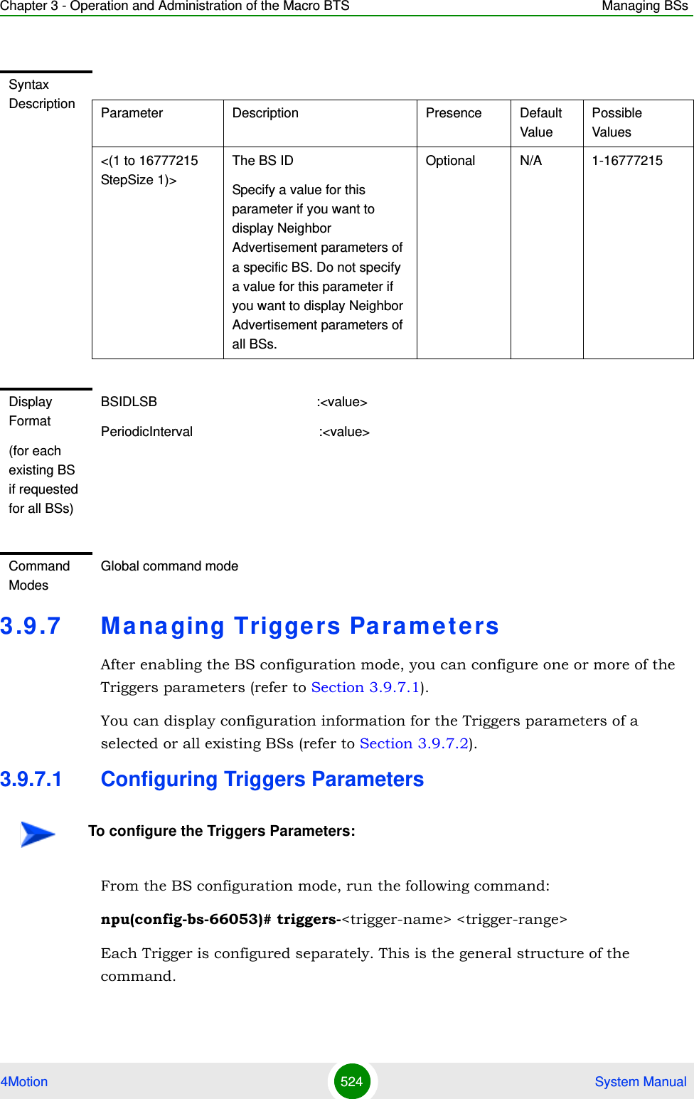
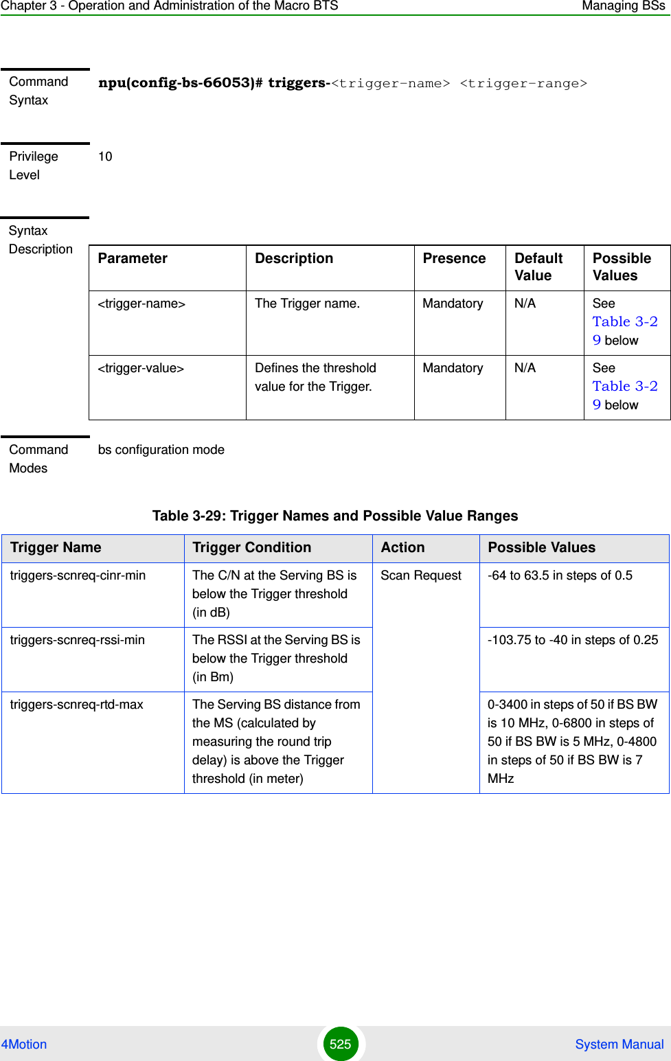
![Chapter 3 - Operation and Administration of the Macro BTS Managing BSs4Motion 526 System Manual3.9.7.2 Displaying Configuration Information for Triggers ParametersTo display configuration information for Triggers parameters, run the following command:npu# show triggers bs [<(1 to 16777215 StepSize 1)> TrigName {scnReqCinrMin | scnReqRssiMin | scnReqRtdMax | hoReqCinrMaxNbs | hoReqRssiMaxNbs | hoReqCinrMargin | hoReqRssiMargin | hoReqRtdMax | hoReqCinrMinSbs | hoReqRssiMinSbs}]Specify the BS ID and Trigger name if you want to display configuration for a particular Trigger. For example, to display the scnReqCinrMin parameters of BS 66053, run the following command:npu# show triggers bs 66053 TrigName scnReqCinrMintriggers-horeq-cinr-margin The C/N at the Neighbor BS minus the C/N at the Serving BS is above the Trigger threshold (in dB)Handover Request-64 to 63.5 in steps of 0.5triggers-horeq-cinr-max The C/N at the Neighbor BS is above the Trigger threshold (in dB)-64 to 63.5 in steps of 0.5triggers-horeq-cinr-min The C/N at the Serving BS is below the Trigger threshold (in dB)-64 to 63.5 in steps of 0.5triggers-horeq-rssi-margin The RSSI at the Neighbor BS minus the RSSI at the Serving BS is above the Trigger threshold (in dBm)-32 to 31.75 in steps of 0.25triggers-horeq-rssi-max The RSSI at the Neighbor BS is above the Trigger threshold (in dBm)-103.75 to -40 in steps of 0.25triggers-horeq-rssi-min The RSSI at the Serving BS is below the Trigger threshold (in dBm)-103.75 to -40 in steps of 0.25triggers-horeq-rtd-max The Serving BS distance from the MS (calculated by measuring the round trip delay) is above the Trigger threshold (in meter)0-3400 in steps of 50 if BS BW is 10 MHz, 0-6800 in steps of 50 if BS BW is 5 MHz, 0-4800 in steps of 50 if BS BW is 7 MHzTable 3-29: Trigger Names and Possible Value RangesTrigger Name Trigger Condition Action Possible Values](https://usermanual.wiki/Alvarion-Technologies/MICRO-25.Manual-p4/User-Guide-1329245-Page-128.png)
![Chapter 3 - Operation and Administration of the Macro BTS Managing BSs4Motion 527 System ManualDo not specify these parameters if you want to view configuration information for all existing BSs. To display information for all BSs, run the following command:npu# show triggers bsCommand Syntaxnpu# show triggers bs [<(1 to 16777215 StepSize 1)> TrigName {scnReqCinrMin | scnReqRssiMin | scnReqRtdMax | hoReqCinrMaxNbs | hoReqRssiMaxNbs | hoReqCinrMargin | hoReqRssiMargin | hoReqRtdMax | hoReqCinrMinSbs | hoReqRssiMinSbs} ]Privilege Level1Syntax Description Parameter Description Presence Default ValuePossible Values<(1 to 16777215 StepSize 1)>The BS ID Specify a value for this parameter if you want to display a specific Trigger of a specific BS. Do not specify a value for this parameter if you want to display all Triggers parameters of all BSs.Optional N/A 1-16777215TrigName {scnReqCinrMin | scnReqRssiMin | scnReqRtdMax | hoReqCinrMaxNbs | hoReqRssiMaxNbs | hoReqCinrMargin | hoReqRssiMargin | hoReqRtdMax | hoReqCinrMinSbs | hoReqRssiMinSbs} ]The Trigger name Specify only if you want to display a specific Trigger of a specific BS. Do not specify if you want to display all Triggers parameters of all BSsscnReqCinrMinscnReqRssiMinscnReqRtdMaxhoReqCinrMaxNbshoReqRssiMaxNbshoReqCinrMarginhoReqRssiMarginhoReqRtdMaxhoReqCinrMinSbshoReqRssiMinSbs}](https://usermanual.wiki/Alvarion-Technologies/MICRO-25.Manual-p4/User-Guide-1329245-Page-129.png)
![Chapter 3 - Operation and Administration of the Macro BTS Managing BSs4Motion 528 System Manual3.9 .8 Ma na ging Scan Ne gotiation ParametersAfter enabling the BS configuration mode, you can execute the following tasks:Configure one or more of the Scan Negotiation parameters (refer to Section 3.9.8.1).Restore the default values of some or all of the Scan Negotiation parameters (refer to Section 3.9.8.2).You can display configuration information for the Scan Negotiation parameters of a selected or all existing BSs (refer to Section 3.9.8.3).3.9.8.1 Configuring Scan Negotiation ParametersFrom the BS configuration mode, run the following command:npu(config-bs-66053)# scanning [enable-modify {true | false}] Display Format(for a selected Trigger)BSIDLSB :<value>scnReqRssiMin :<value>Command ModesGlobal command modeTo configure the Scan Negotiation Parameters:Command Syntaxnpu(config-bs-66053)# scanning [enable-modify {true | false} ] Privilege Level10](https://usermanual.wiki/Alvarion-Technologies/MICRO-25.Manual-p4/User-Guide-1329245-Page-130.png)
![Chapter 3 - Operation and Administration of the Macro BTS Managing BSs4Motion 529 System Manual3.9.8.2 Restoring the Default Value of Scan Negotiation ParametersTo restore the Scan Negotiation enable-modify parameter to the default value, run the following command:npu(config-bs-66053)# no scanning [enable-modify]3.9.8.3 Displaying Configuration Information for Scan Negotiation ParametersTo display configuration information for Scan Negotiation parameters, run the following command:Syntax Description Parameter Description Presence Default ValuePossible Values[enable-modify {TRUE | FALSE} ]Determines whether the BS will modify unfeasible scan profiles requested by MSs.Note: If TRUE the BS will modify unfeasible scan profile requests and if FALSE the BS will deny the requests. Optional true truefalseCommand Modesbs configuration modeNOTERefer to Section 3.9.8.1 for a description and default value of this parameter.Command Syntaxnpu(config-bs-66053)# no scanning [enable-modify ][Privilege Level10Command Modesbs configuration mode](https://usermanual.wiki/Alvarion-Technologies/MICRO-25.Manual-p4/User-Guide-1329245-Page-131.png)
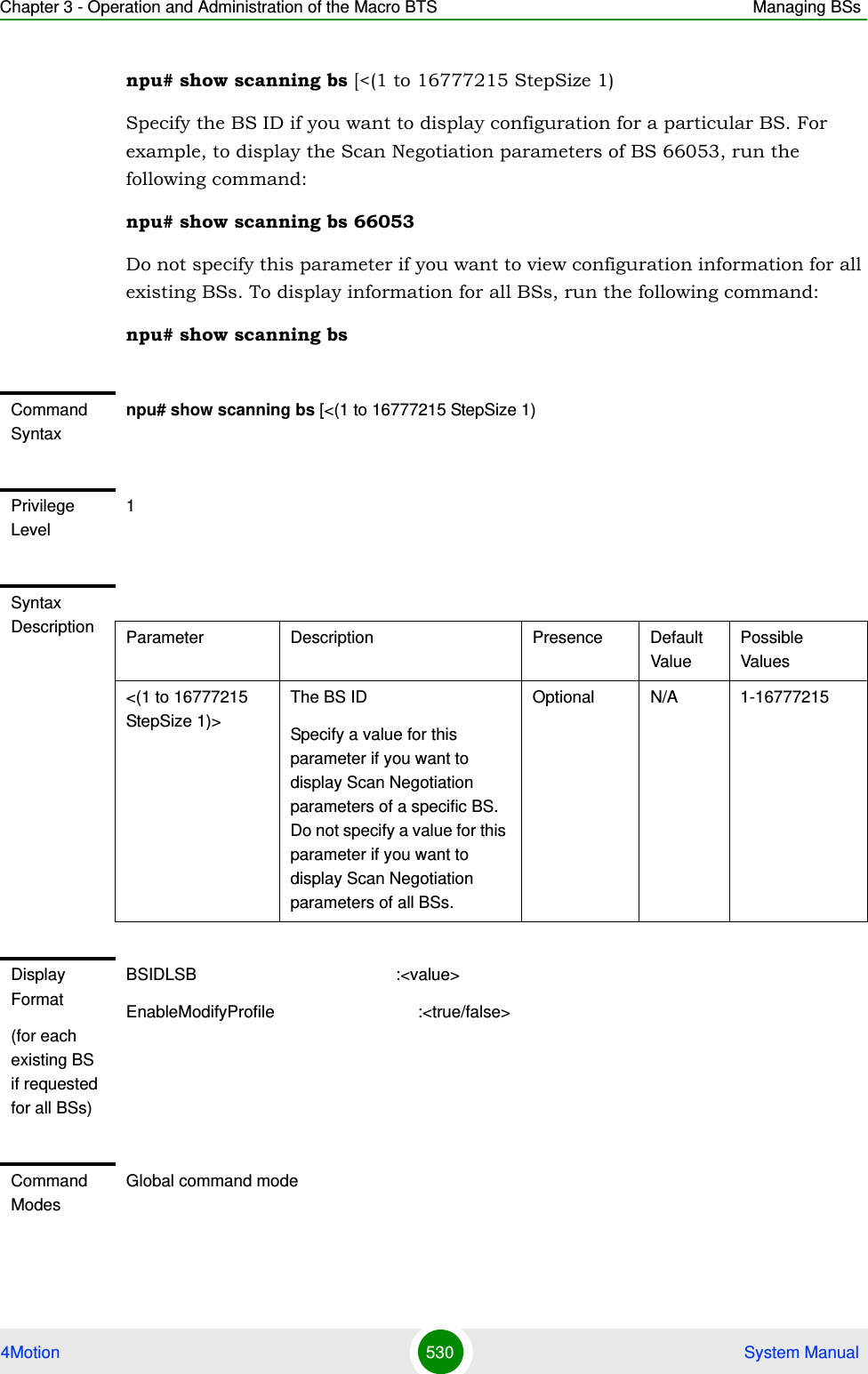
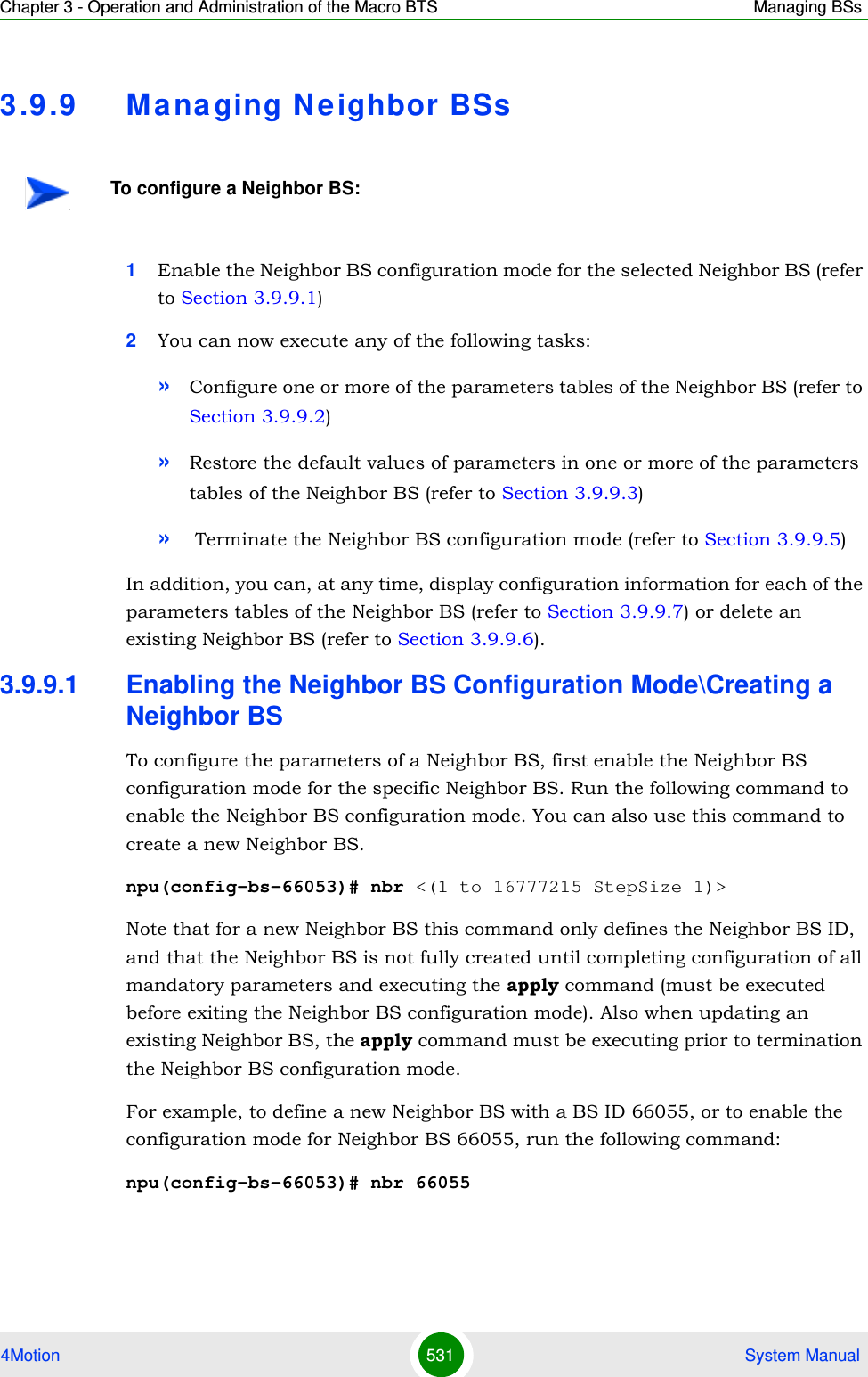
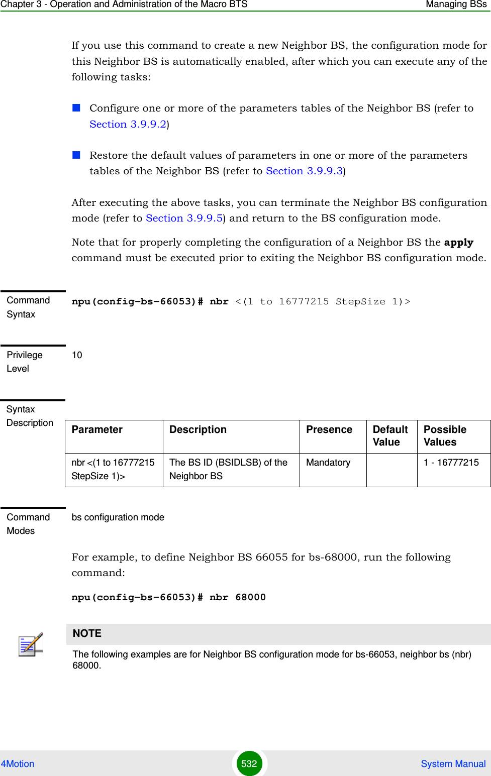
![Chapter 3 - Operation and Administration of the Macro BTS Managing BSs4Motion 533 System Manual3.9.9.2 Configuring Neighbor BS ParametersAfter enabling the Neighbor BS configuration mode you can configure the following parameters tables:General (refer to Section 3.9.9.2.1)Required C/N Level (refer to Section 3.9.9.2.2)Triggers (refer to Section 3.9.9.2.3)Specific BS Triggers (refer to Section 3.9.9.2.43.9.9.2.1 Configuring General Neighbor BS ParametersThe General Neighbor BS Parameters table enables defining the general parameters of the Neighbor BS.To configure the General Neighbor BS parameters, run the following command:npu(config-bs-66053-nbr-68000)# general [syncind {unsynchronized | timeSynchronized | timeAndFrequencySynchronized}] [eirp <(-128 to 127 StepSize 1)>] [bw {fiveMHz | tenMHz | sevenMHz}] [feedbackzone-permbase <(0 to 69 StepSize 1)>] [ucd-configchangecount <(0 to 255 StepSize 1)>] [dcd-configchangecount <(0 to 255 StepSize 1)>] [eirx-pir-max <(-140 to -40 StepSize 1)>] [frequency <(2022.5 to 2217.5 StepSize 0.125) | (2302.5 to 2397.5 StepSize 0.125) | (2487.5 to 2687.5 StepSize 0.125) | (3302.5 to 3397.5 StepSize 0.125) | (3402.5 to 3597.5 StepSize 0.125) | (3602.5 to 3797.5 StepSize 0.125)>] [preamble-idx <(0 to 255 StepSize 1)>] [paging-grp-id <(0 to 65535 StepSize 1)> ] [nbr-strt-rng-codes <(0 to 255 StepSize 1)> ] [bsNeighborBsDlDataMIMOMode {matrixAorB | beamforming} ]IMPORTANTAfter completing the Neighbor BS configuration, do not forget to execute the apply command before exiting the Neighbor BS configuration mode:npu(config-bs-66053-nbr-68000)# applyIMPORTANTWhen creating a new Neighbor BS, all mandatory Neighbor BS General parameters must be configured.](https://usermanual.wiki/Alvarion-Technologies/MICRO-25.Manual-p4/User-Guide-1329245-Page-135.png)
![Chapter 3 - Operation and Administration of the Macro BTS Managing BSs4Motion 534 System ManualCommand Syntaxnpu(config-bs-66053-nbr-68000)# general [syncind {unsynchronized | timeSynchronized | timeAndFrequencySynchronized} ] [eirp <(-128 to 127 StepSize 1)> ] [bw {fiveMHz | tenMHz | sevenMHz} ] [feedbackzone-permbase <(0 to 69 StepSize 1)> ] [ucd-configchangecount <(0 to 255 StepSize 1)>] [dcd-configchangecount <(0 to 255 StepSize 1)> ] [eirx-pir-max <(-140 to -40 StepSize 1)> ] [frequency <(2022.5 to 2217.5 StepSize 0.125) | (2302.5 to 2397.5 StepSize 0.125) | (2487.5 to 2687.5 StepSize 0.125) | (3302.5 to 3397.5 StepSize 0.125) | (3402.5 to 3597.5 StepSize 0.125) | (3602.5 to 3797.5 StepSize 0.125)> ] [preamble-idx <(0 to 255 StepSize 1)> ] [paging-grp-id <(0 to 65535 StepSize 1)> ] [nbr-strt-rng-codes <(0 to 255 StepSize 1)> ] [bsNeighborBsDlDataMIMOMode {matrixAorB | beamforming} ]Privilege Level10Syntax Description Parameter Description Presence Default ValuePossible Values[syncind {unsynchronized | timeSynchronized | timeAndFrequencySynchronized} ]Time/Frequency synchronization indicator.In the current release should always be set to timeAndFrequencySynchronized.Optional timeAndFrequencySynchronizedunsynchronizedtimeSynchronizedtimeAndFrequencySynchronized[eirp <(-128 to 127 StepSize 1)> ]Neighbor BS EIRP Mandatory When creating a new Neighbor BS.N/A -128 to 127](https://usermanual.wiki/Alvarion-Technologies/MICRO-25.Manual-p4/User-Guide-1329245-Page-136.png)
![Chapter 3 - Operation and Administration of the Macro BTS Managing BSs4Motion 535 System Manual[bw {fiveMHz | tenMHz | sevenMHz} ]The bandwidth of neighbor BS.Should be taken from Baseband bandwidth parameter of the relevant BS (see Section 3.9.11.2)Mandatory When creating a new Neighbor BS.N/A fiveMHztenMHzsevenMHz[feedbackzone-permbase <(0 to 69 StepSize 1)> ]The first uplink zone permutation base of the neighbor BS.In current release this equals the feedback zone permutation base (see Section 3.9.12.5.4)Mandatory When creating a new Neighbor BS.N/A 0 - 69[ucd-configchangecount <(0 to 255 StepSize 1)>]UCD configuration change count of neighbor BSIn the current release must be set to 0.Mandatory When creating a new Neighbor BS.N/A 0 - 255must be set to 0[dcd-configchangecount <(0 to 255 StepSize 1)> ] DCD configuration change count of neighbor BSIn the current release must be set to 0.Mandatory When creating a new Neighbor BS.N/A 0 - 255must be set to 0eirx-pir-max <(-140 to -40 StepSize 1)>The required effective isotropic received power at the Neighbor BS for Initial ranging, in dBm.Should be taken from Power Control maxeirxp (see Section 3.9.4.5.2)Optional -124 -140 to -40](https://usermanual.wiki/Alvarion-Technologies/MICRO-25.Manual-p4/User-Guide-1329245-Page-137.png)
![Chapter 3 - Operation and Administration of the Macro BTS Managing BSs4Motion 536 System Manual[frequency <(2022.5 to 2217.5 StepSize 0.125) | (2302.5 to 2397.5 StepSize 0.125) | (2487.5 to 2687.5 StepSize 0.125) | (3302.5 to 3397.5 StepSize 0.125) | (3402.5 to 3597.5 StepSize 0.125) | (3602.5 to 3797.5 StepSize 0.125)> ]Downlink center frequency of neighbor BS.Should be taken from RF frequency parameter of the relevant BS (see Section 3.9.10.2)Mandatory When creating a new Neighbor BS.N/A 2022.5 to 2217.5 in steps of 0.1252302.5 to 2397.5 in steps of 0.1252487.5 to 2687.5 in steps of 0.1253302.5 to 3397.5 in steps of 0.1253402.5 to 3597.5 in steps of 0.1253602.5 to 3797.5 in steps of 0.125[preamble-idx <(0 to 113 StepSize 1)> ]Neighbor BS Preamble Index.When translated to an 8 bits binary string, bits 0-6 of this parameter are used to indicate the neighbor BS preamble index. Bit 7 is used to indicate the neighbor BS reuse type for CINR measurement for handover purposes Bits 0-6 should be the same as preamble-idx in displayed information of Airframe General parameters of the relevant BS (see Section 3.9.12.5.1Mandatory When creating a new Neighbor BS.N/A 0 - 255[paging-grp-id <(0 to 65535 StepSize 1)> ]The neighbor BS Paging Group Id Should be taken from Idle Mode paging-group-id parameter of the relevant BS (see Section 3.9.23) Optional 0 0 - 65535](https://usermanual.wiki/Alvarion-Technologies/MICRO-25.Manual-p4/User-Guide-1329245-Page-138.png)
![Chapter 3 - Operation and Administration of the Macro BTS Managing BSs4Motion 537 System Manual3.9.9.2.2 Configuring the Neighbor BS Required C/N Level ParametersThe Neighbor BS Required C/N Levels table enables defining the Carrier to Noise Ratios required for various types of transmissions. The configured values should be the same as those defined for the applicable Power Control Required C/N Level parameters (see Section 3.9.4.5.3) in the neighbor BS.To configure the Neighbor BS Required C/N Levels, run the following command:npu(config-bs-66053-nbr-68000)# requiredcnr [ack <(-20 to 50 StepSize 1)>] [cqi <(-20 to 50 StepSize 1)>] [cdma <(-20 to 50 StepSize 1)>] [qpsk-1by2 <(-20 to 50 StepSize 1)>] [qpsk-3by4 <(-20 to 50 StepSize 1)>] [qam16-1by2 <(-20 to 50 StepSize 1)>] [qam16-3by4 <(-20 to 50 StepSize 1)>] [qam64-1by2 <(-20 to 50 StepSize 1)>] [qam64-2by3 <(-20 to 50 StepSize 1)>] [qam64-3by4 <(-20 to 50 StepSize 1)>] [qam64-5by6 <(-20 to 50 StepSize 1)>][nbr-strt-rng-codes <(0 to 255 StepSize 1)> ]The neighbor BS starting number; S; of the group of codes used for this uplink.Should be taken from Ranging General, start-of-rng-codes parameters of the relevant BS (see Section 3.9.19.2)Optional 0 0 -255[bsNeighborBsDlDataMIMOMode {matrixAorB | beamforming} ]The diversity mode used by the neighbor BS. Should be taken from Airframe dldiversity mode parameter of the relevant BS (see Section 3.9.12.2.3)Optional matrixA0rB matrixAorBbeamformingCommand Modesbs neighbor bs configuration mode](https://usermanual.wiki/Alvarion-Technologies/MICRO-25.Manual-p4/User-Guide-1329245-Page-139.png)
![Chapter 3 - Operation and Administration of the Macro BTS Managing BSs4Motion 538 System ManualCommand Syntaxnpu(config-bs-66053-nbr-68000)# requiredcnr [ack <(-20 to 50 StepSize 1)> ] [cqi <(-20 to 50 StepSize 1)> ] [cdma <(-20 to 50 StepSize 1)> ] [qpsk-1by2 <(-20 to 50 StepSize 1)> ] [qpsk-3by4 <(-20 to 50 StepSize 1)> ] [qam16-1by2 <(-20 to 50 StepSize 1)> ] [qam16-3by4 <(-20 to 50 StepSize 1)> ] [qam64-1by2 <(-20 to 50 StepSize 1)> ] [qam64-2by3 <(-20 to 50 StepSize 1)> ] [qam64-3by4 <(-20 to 50 StepSize 1)> ] [qam64-5by6 <(-20 to 50 StepSize 1)> ]Privilege Level10Syntax Description Parameter Description Presence Default ValuePossible Values[ack <(-20 to 50 StepSize 1)> ]The C/N in dB required for sending ACK, reported by the Neighbor BS to the MS for power control purposes.Optional 7 -20 to 50[cqi <(-20 to 50 StepSize 1)> ]The C/N in dB required for sending CQI, reported by the Neighbor BS to the MS for power control purposes.Optional 0 -20 to 50 [cdma <(-20 to 50 StepSize 1)> ]The C/N in dB required for transmitting CDMA, reported by the Neighbor BS to the MS for power control purposes.Optional 0 -20 to 50[qpsk-1by2 <(-20 to 50 StepSize 1)> ]The C/N in dB required for transmitting using QPSK 1/2, reported by the Neighbor BS to the MS for power control purposes.Optional 14 -20 to 50[qpsk-3by4<(-20 to 50 StepSize 1)> ]The C/N in dB required for transmitting using QPSK 3/4, reported by the Neighbor BS to the MS for power control purposes.Optional 16 -20 to 50](https://usermanual.wiki/Alvarion-Technologies/MICRO-25.Manual-p4/User-Guide-1329245-Page-140.png)
![Chapter 3 - Operation and Administration of the Macro BTS Managing BSs4Motion 539 System Manual3.9.9.2.3 Configuring Neighbor BS Triggers ParametersTo configure the Neighbor BS Triggers parameters, run the following command:npu(config-bs-66053-nbr-68000)# triggers-<trigger-name> <trigger-range>Each Trigger is configured separately. This is the general structure of the command.The configured trigger names and values should be the same as those defined for the applicable Triggers parameters (see Section 3.9.7.2) in the neighbor BS. [qam16-1by2 <(-20 to 50 StepSize 1)> ]The C/N in dB required for transmitting using 16QAM 1/2, reported by the Neighbor BS to the MS for power control purposes.Optional 18 -20 to 50[qam16-3by4 <(-20 to 50 StepSize 1)> ]The C/N in dB required for transmitting using 16QAM 3/4, reported by the Neighbor BS to the MS for power control purposes.Optional 22 -20 to 50qam64-1by2 <(-20 to 50 StepSize 1)> ]The C/N in dB required for transmitting using 64QAM 1/2, reported by the Neighbor BS to the MS for power control purposes.Optional 23 -20 to 50[qam64-2by3 <(-20 to 50 StepSize 1)> ]The C/N in dB required for transmitting using 64QAM 2/3, reported by the Neighbor BS to the MS for power control purposes.Optional 23 -20 to 50[qam64-3by4 <(-20 to 50 StepSize 1)> ]The C/N in dB required for transmitting using 64QAM 3/4, reported by the Neighbor BS to the MS for power control purposes.Optional 23 -20 to 50[qam64-5by6 <(-20 to 50 StepSize 1)> ]he C/N in dB required for transmitting using 64QAM 5/6, reported by the Neighbor BS to the MS for power control purposes.Optional 23 -20 to 50Command Modesbs neighbor bs configuration mode](https://usermanual.wiki/Alvarion-Technologies/MICRO-25.Manual-p4/User-Guide-1329245-Page-141.png)
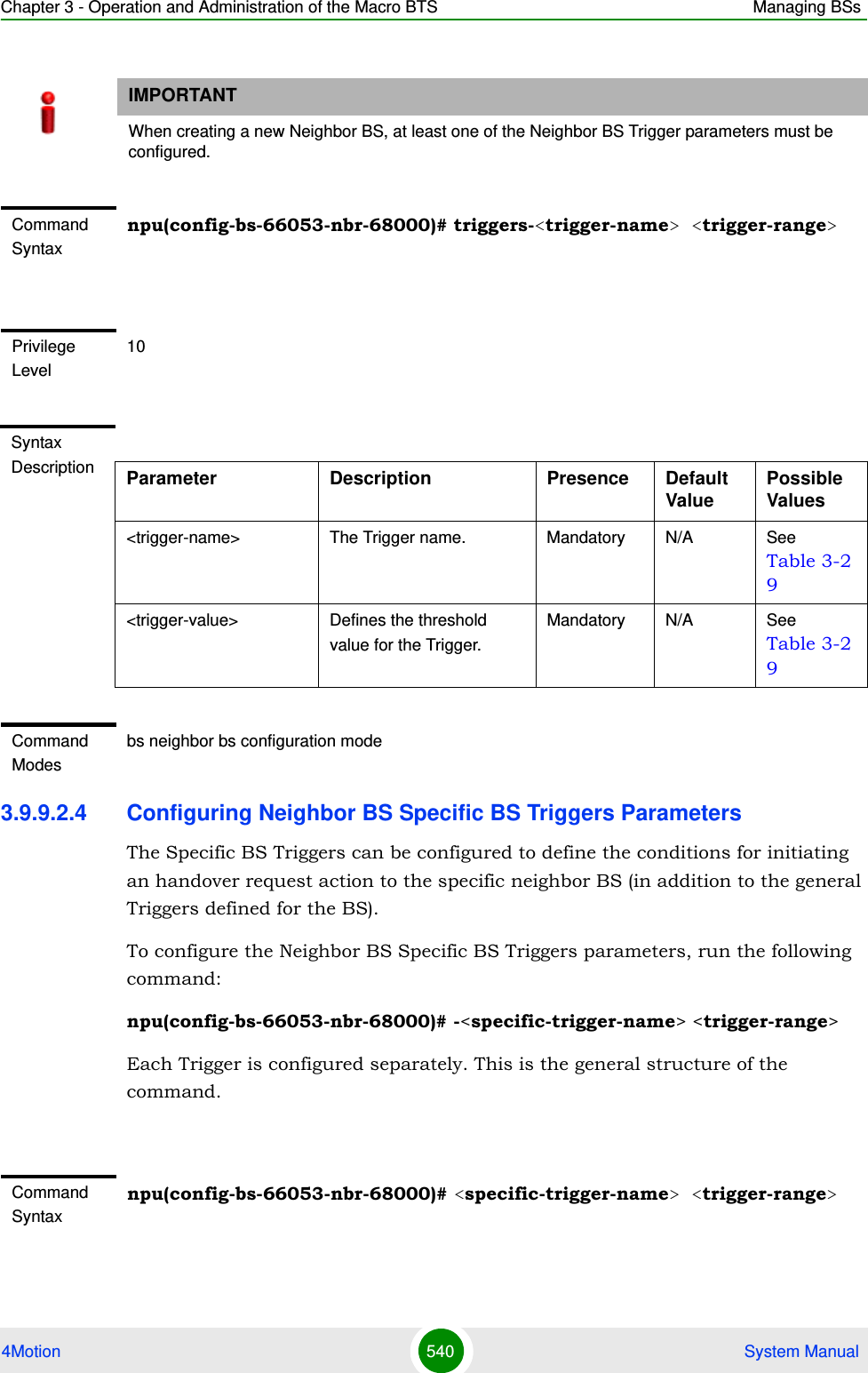
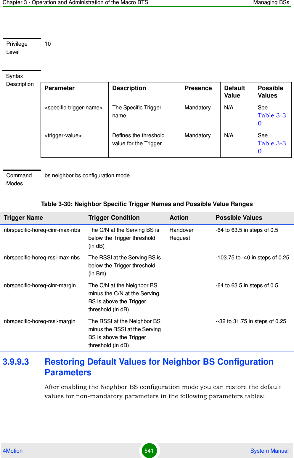
![Chapter 3 - Operation and Administration of the Macro BTS Managing BSs4Motion 542 System ManualGeneral (refer to Section 3.9.9.3.1)Required C/N Level (refer to Section 3.9.9.3.2)3.9.9.3.1 Restoring the Default Values of Neighbor BS General ParametersTo restore one or all of the Neighbor BS non-mandatory General parameters to their default values, run the following command:npu(config-bs-66053-nbr-68000)# no general [syncind] [eirx-pir-max] [paging-grp-id ] [nbr-strt-rng-codes ] [bsNeighborBsDlDataMIMOMode ]You can restore only some parameters to the default values by specifying only those parameters. For example, to restore only the syncind to the default value, run the following command:npu(config-bs-66053-nbr-68000)# no general syncindThe parameter will be restored to its default value, while the other parameters will remain unchanged.To restore all non-mandatory parameters to their default value, run the following command:npu(config-bs-66053-nbr-68000)# no general3.9.9.3.2 Restoring the Default Values of Neighbor BS Required C/N Level ParametersTo restore some or all of the Neighbor BS Required C/N Levels parameters to their default values, run the following command:NOTERefer to Section 3.9.9.2.1 for a description and default values of these parameters.Command Syntaxnpu(config-bs-66053-nbr-68000)# no general [syncind ] [eirx-pir-max ][paging-grp-id ][nbr-strt-rng-codes][bsNeighborBsDlDataMIMOMode ]Privilege Level10Command Modesbs neighbor bs configuration mode](https://usermanual.wiki/Alvarion-Technologies/MICRO-25.Manual-p4/User-Guide-1329245-Page-144.png)
![Chapter 3 - Operation and Administration of the Macro BTS Managing BSs4Motion 543 System Manualnpu(config-bs-66053-bs-68000)# no requiredcnr [ack] [cqi] [cdma] [qpsk-1by2] [qpsk-3by4] [qam16-1by2] [qam16-3by4] [qam64-1by2] [qam64-2by3] [qam64-3by4] [qam64-5by6]You can restore only some parameters to their default values by specifying only those parameter. For example, to restore only the ack and cqi parameters to the default values, run the following command:npu(config-bs-66053-nbr-68000)# no requiredcnr ack cqiThese parameters will be restored to their default value, while the other parameters will remain unchanged.To restore all Neighbor BS Required C/N Levels parameters to their default value, run the following command:npu(config-bs-66053-nbr-68000)# no requiredcnr3.9.9.4 Deleting Neighbor BS Triggers/Specific BS TriggersAfter enabling the Neighbor BS configuration mode you can delete previously configured triggers or specific BS triggers:3.9.9.4.1 Deleting Neighbor BS TriggersTo delete an entry from the neighbor BS triggers table run the following command:npu(config-bs-66053-nbr-68000)# no <trigger-name>NOTERefer to Section 3.9.9.2.2 for a description and default values of these parameters.Command Syntaxnpu(config-bs-66053-nbr-68000)# no requiredcnr [ack ] [cqi ] [cdma ] [qpsk-1by2 ] [qpsk-3by4 ] [qam16-1by2 ] [qam16-3by4 ] [qam64-1by2 ] [qam64-2by3 ] [qam64-3by4 ] [qam64-5by6 ]Privilege Level10Command Modesbs neighbor bs configuration mode](https://usermanual.wiki/Alvarion-Technologies/MICRO-25.Manual-p4/User-Guide-1329245-Page-145.png)
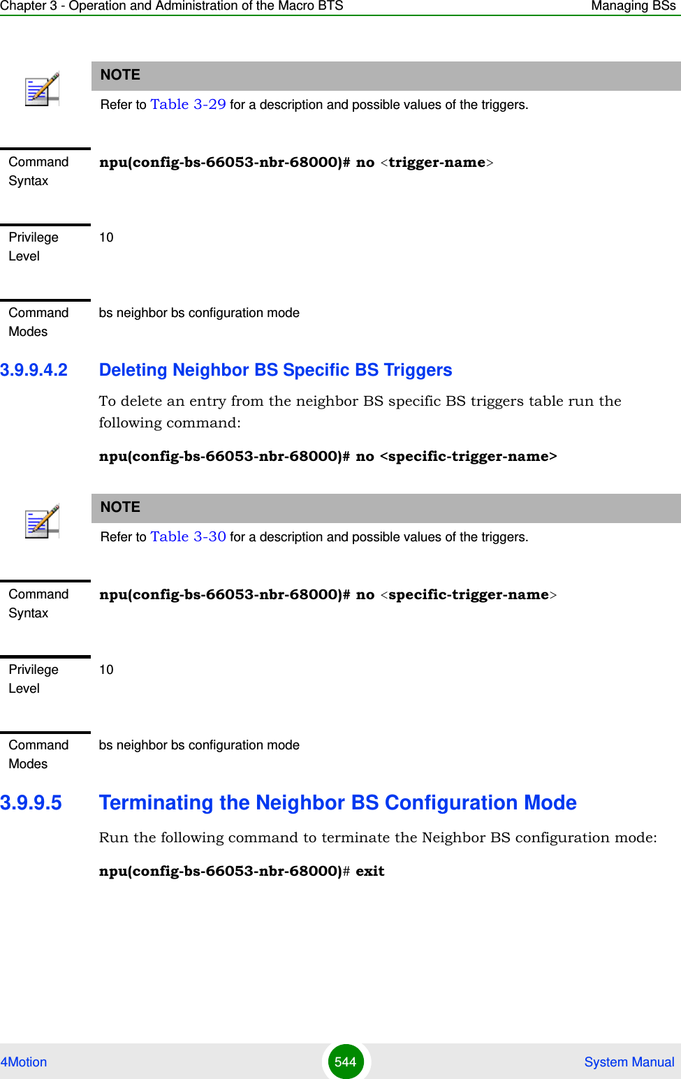
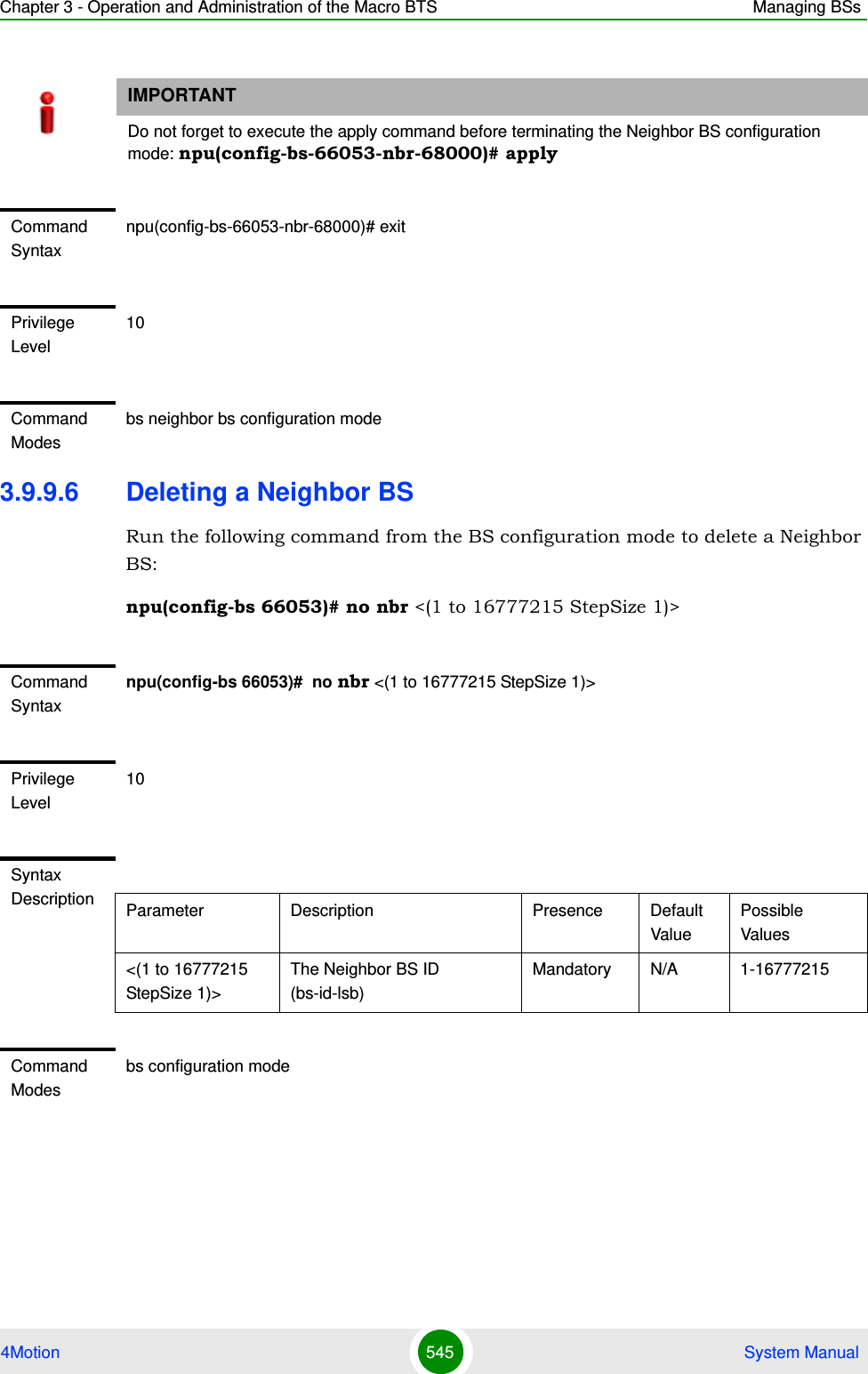
![Chapter 3 - Operation and Administration of the Macro BTS Managing BSs4Motion 546 System Manual3.9.9.7 Displaying Configuration Information for Neighbor BS ParametersYou can display the current configuration information for the following Neighbor BS parameters tables:General (refer to Section 3.9.9.7.1) Required C/N Level (refer to Section 3.9.9.7.2)Triggers (refer to Section 3.9.9.7.3)All (refer to Section 3.9.9.7.5)3.9.9.7.1 Displaying Configuration Information for Neighbor BS General ParametersTo display configuration for the Neighbor BS General parameters, run the following command:npu# show nbr-general bs [<(1 to 16777215 StepSize 1)> bs-id-lsb <(1 to 16777215 StepSize 1)>]Specify the BS ID and the Neighbor BS ID (bs-id-lsb) if you want to display configuration for a particular Neighbor BS in a particular BS. For example, to display the General parameters of Neighbor BS 68000 in BS 66503, run the following command:npu# show nbr-general bs 66053 bs-id-lsb 68000Do not specify these parameters if you want to view configuration information for all existing Neighbor BSs in all existing BSs. To display information for all Neighbor BSs in all BSs, run the following command:npu# show nbr-general bsCommand Syntaxnpu# show nbr-general bs [<(1 to 16777215 StepSize 1)> bs-id-lsb <(1 to 16777215 StepSize 1)> ]Privilege Level1](https://usermanual.wiki/Alvarion-Technologies/MICRO-25.Manual-p4/User-Guide-1329245-Page-148.png)