Alvarion Technologies MICRO-25 Microbase station transceiver User Manual 4Motion System Manual
Alvarion Technologies Ltd. Microbase station transceiver 4Motion System Manual
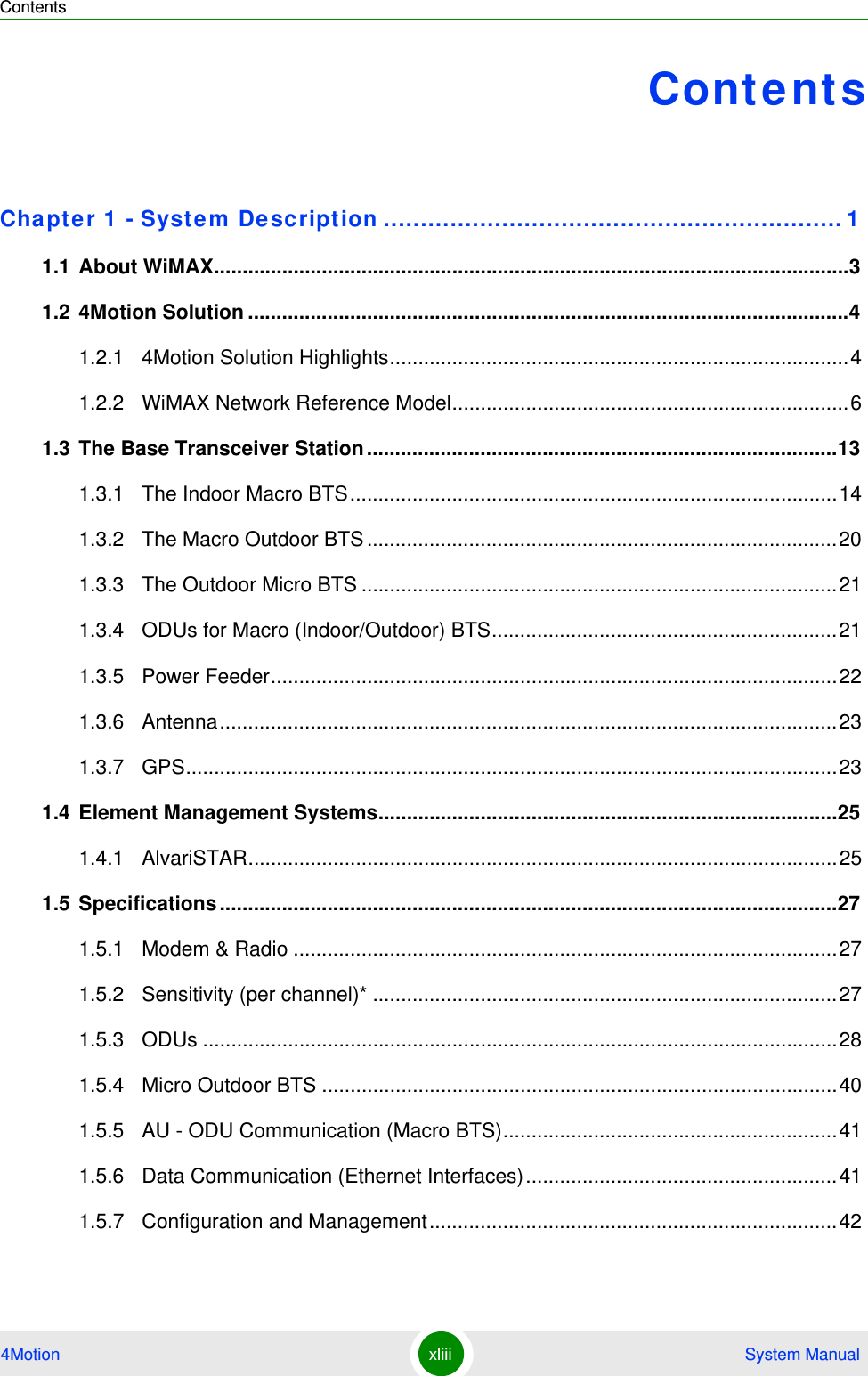
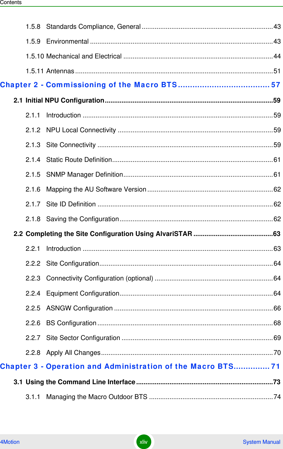
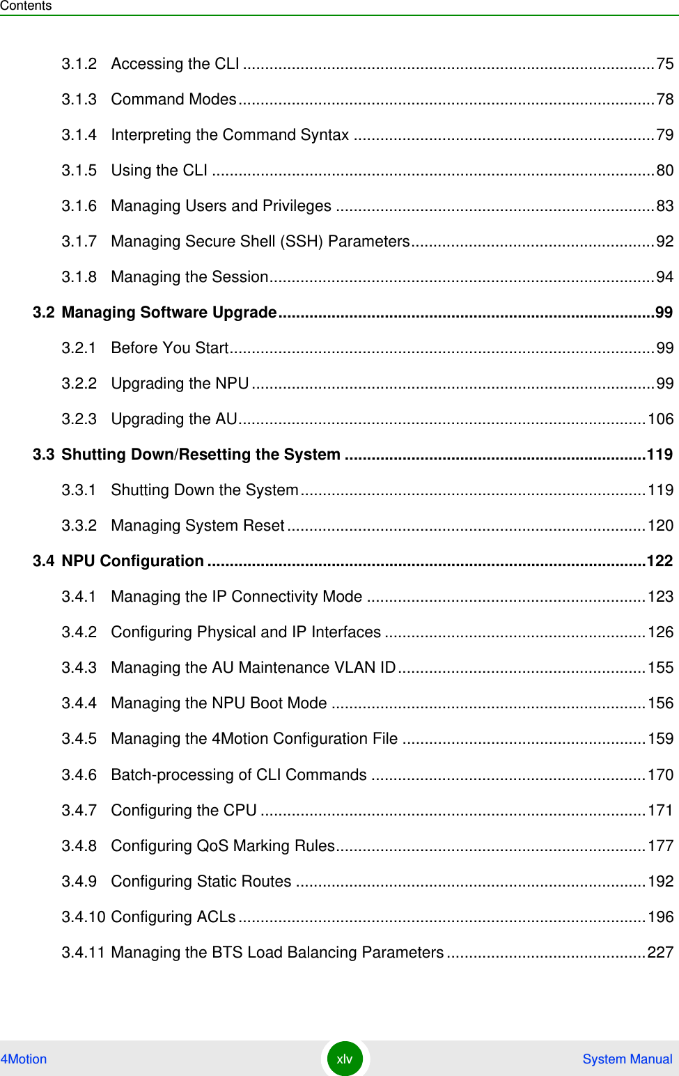
Contents
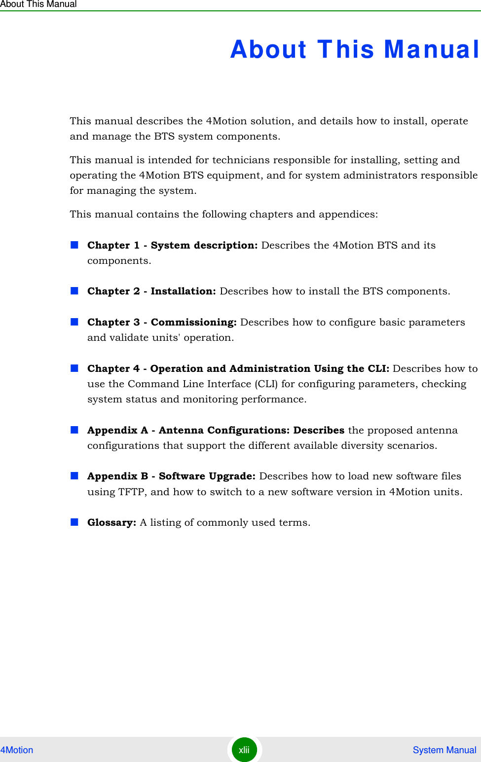
- 1. Manual p1
- 2. Manual p2
- 3. Manual p3
- 4. Manual p4
- 5. Manual p5
Manual p1
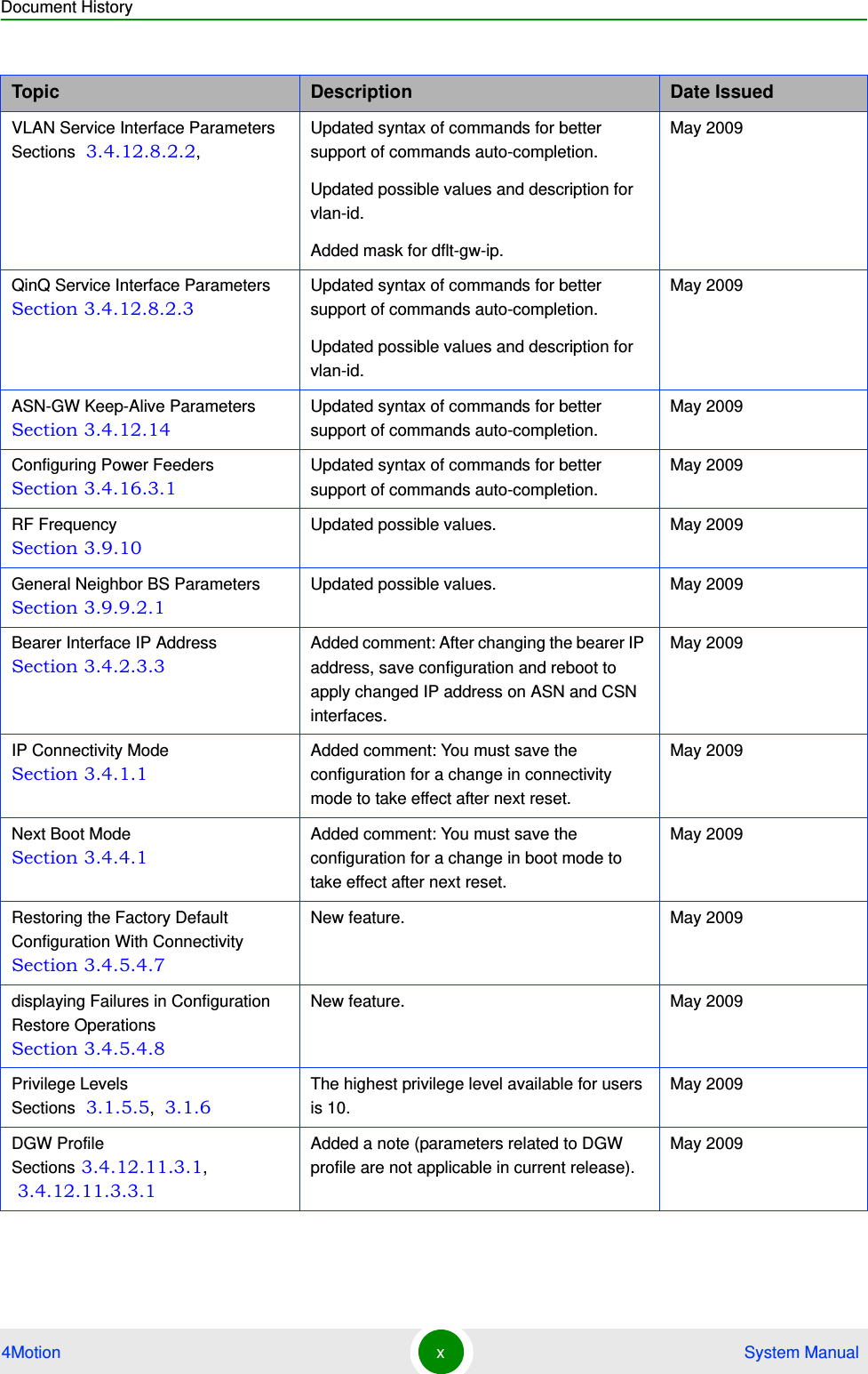
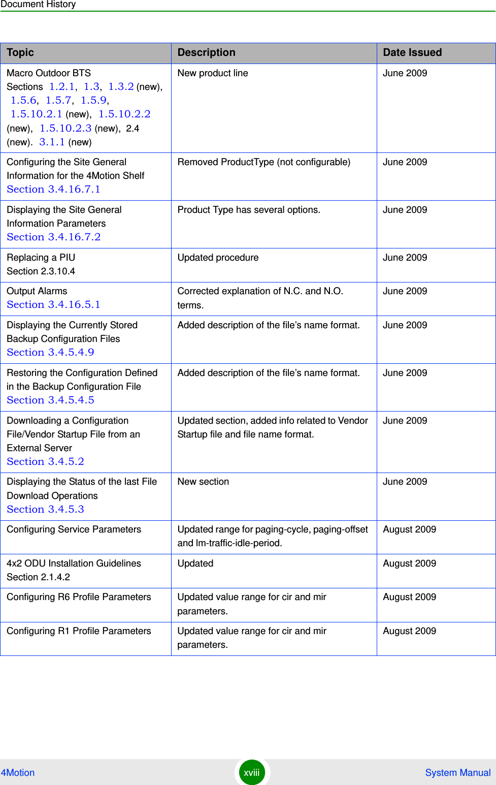
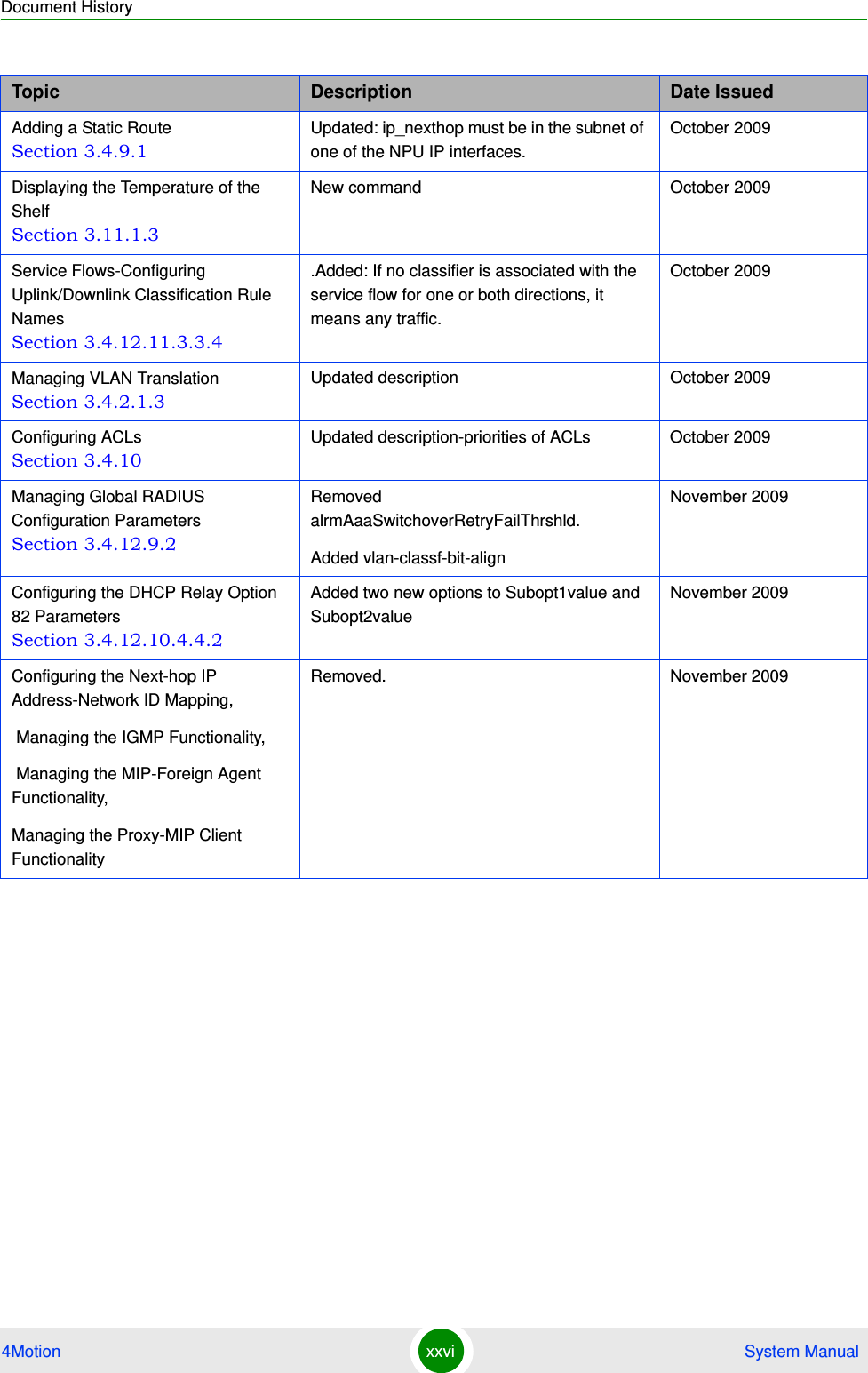
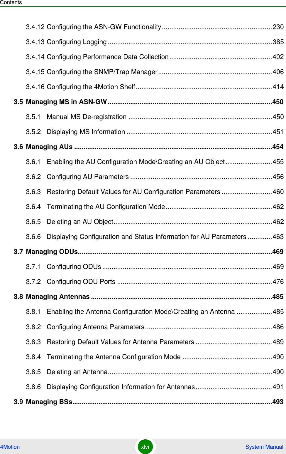
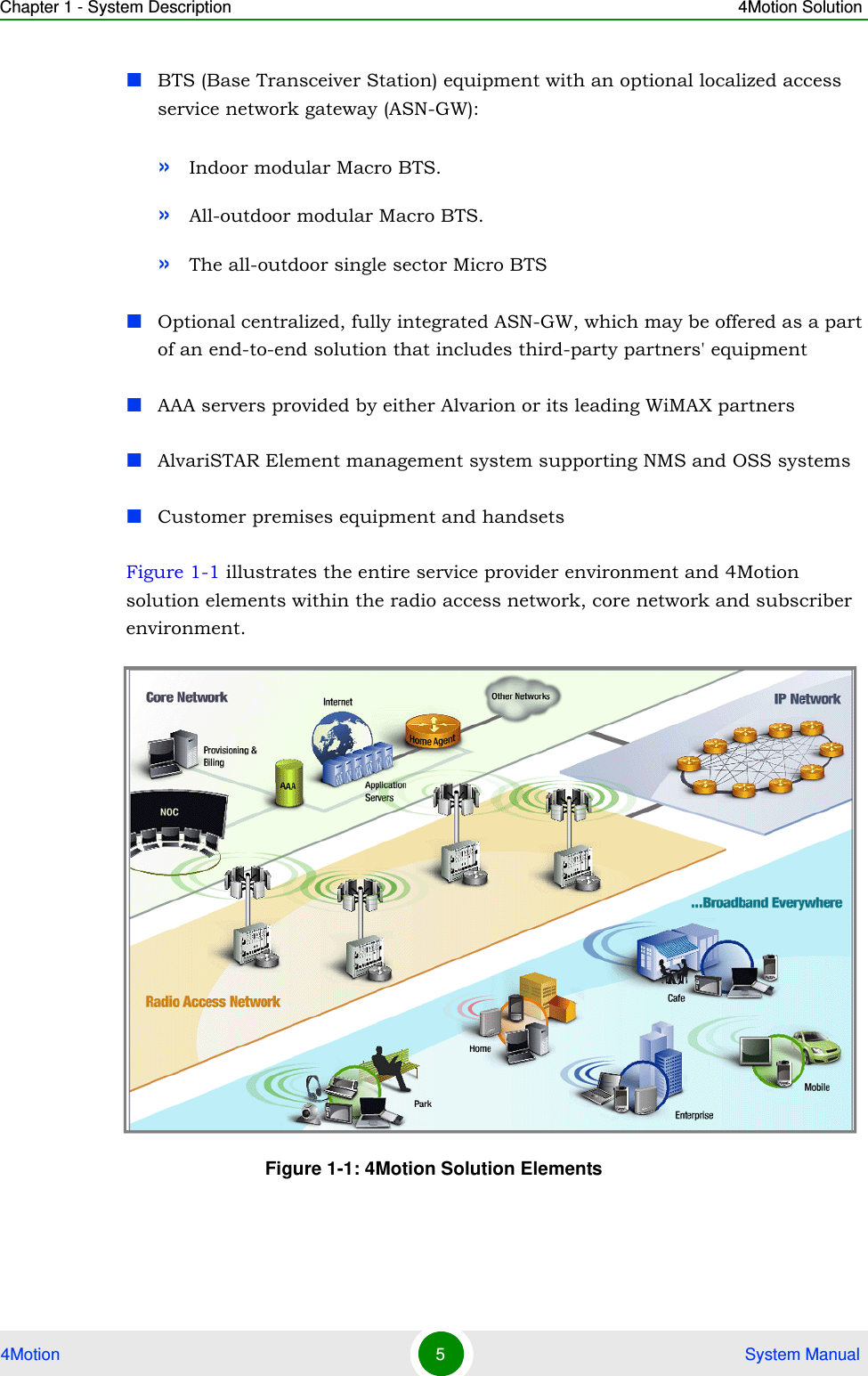
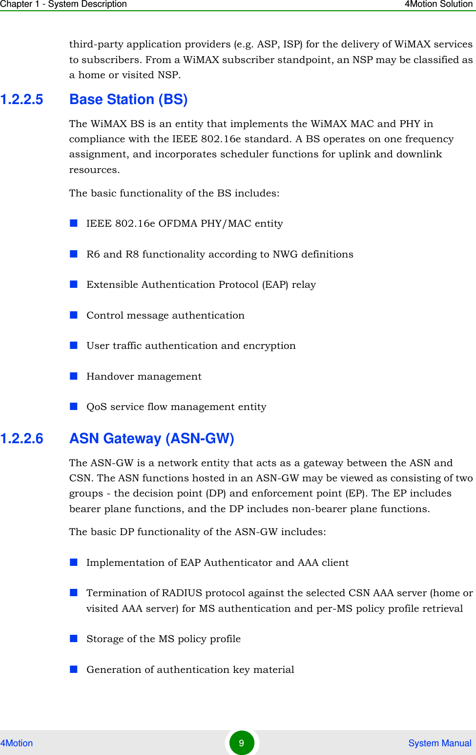
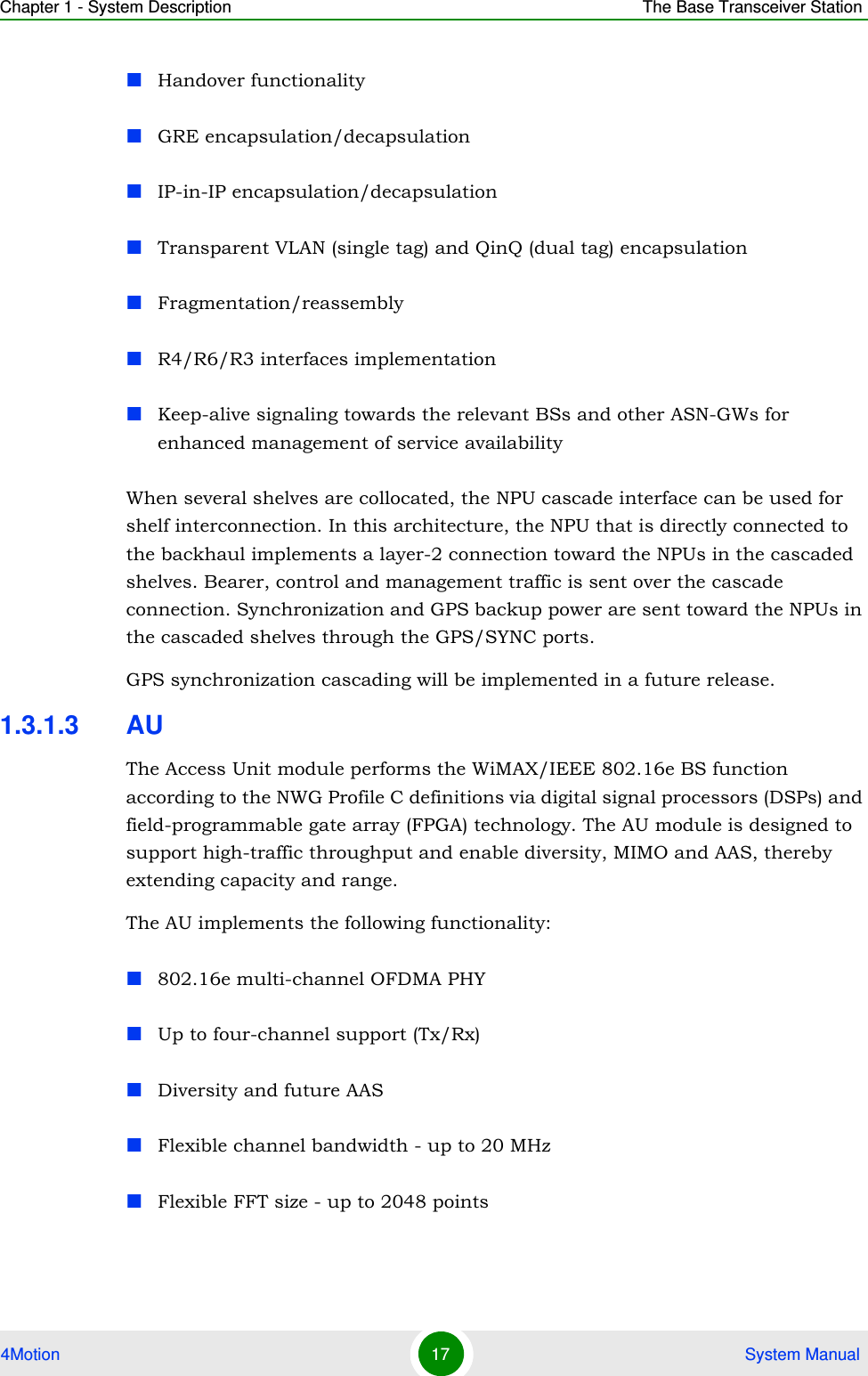
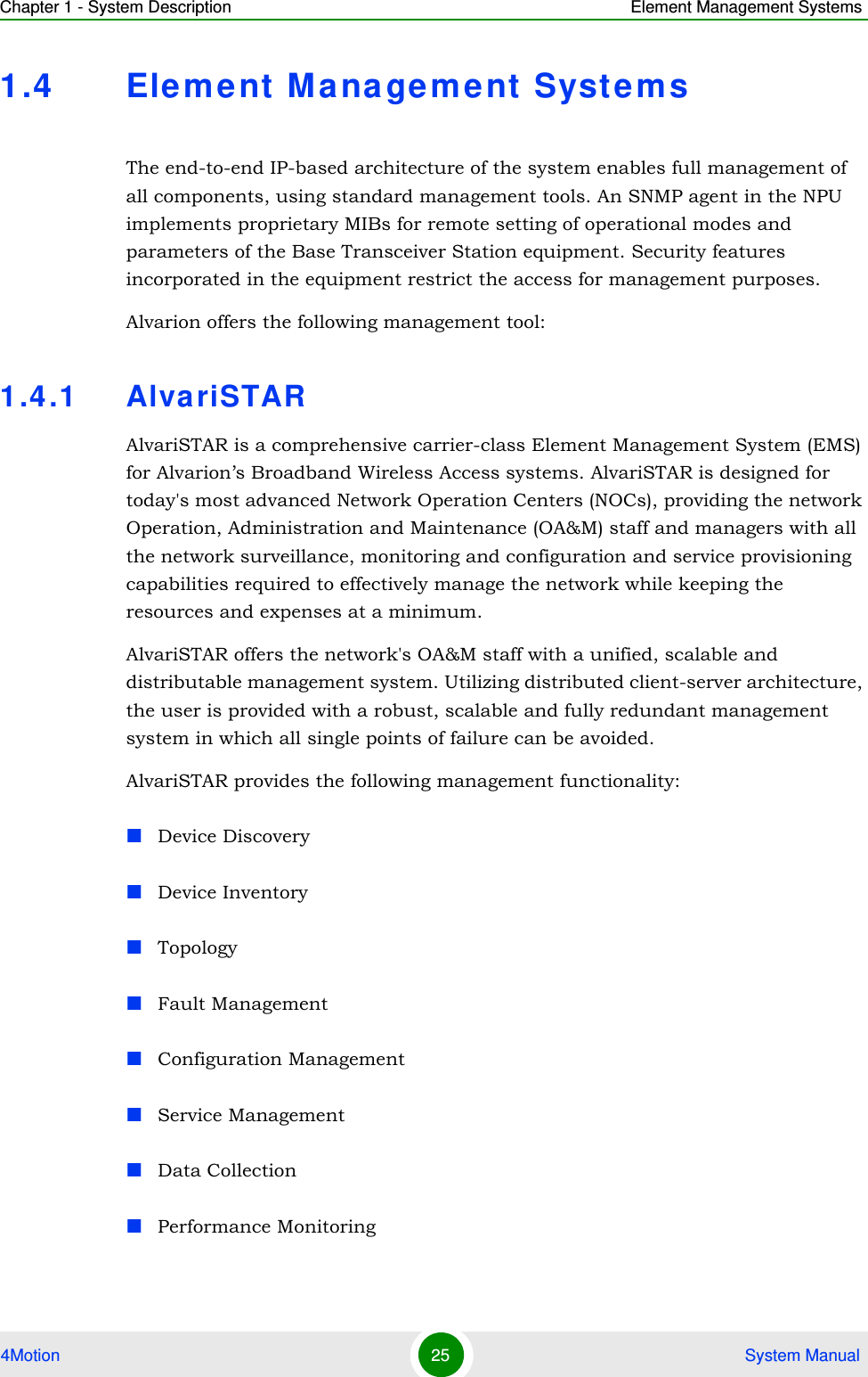

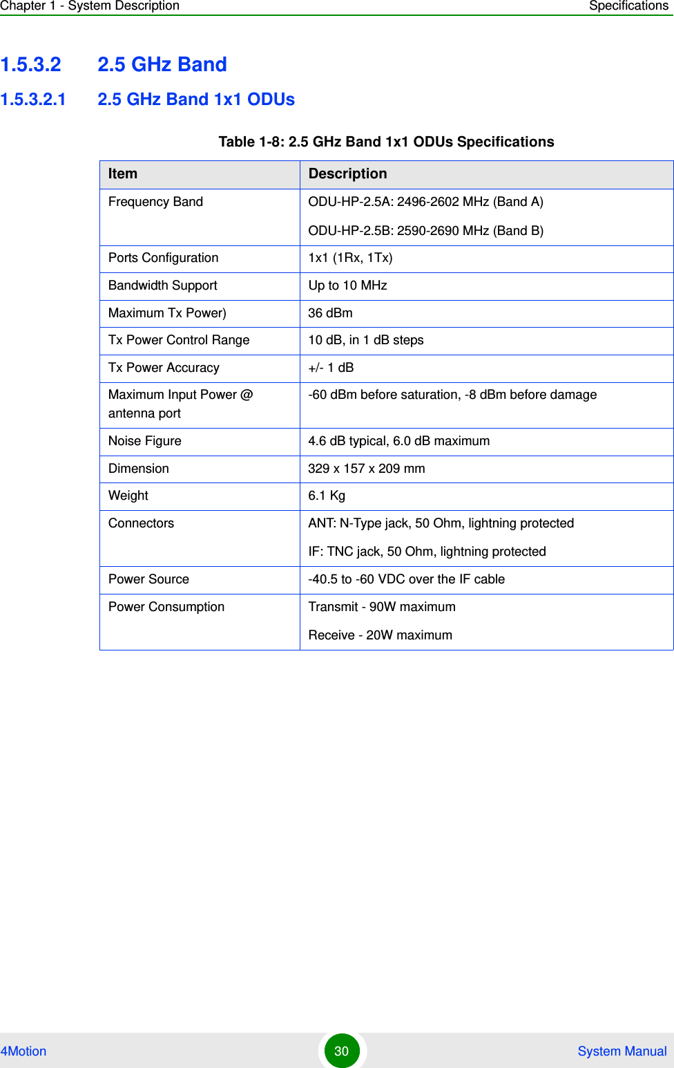
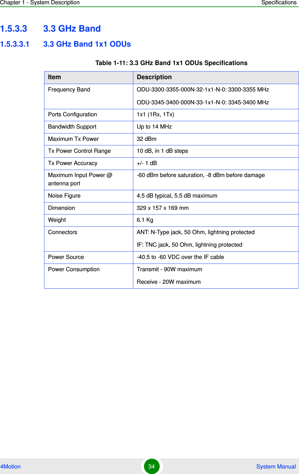
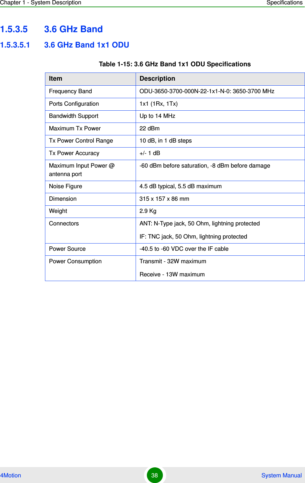
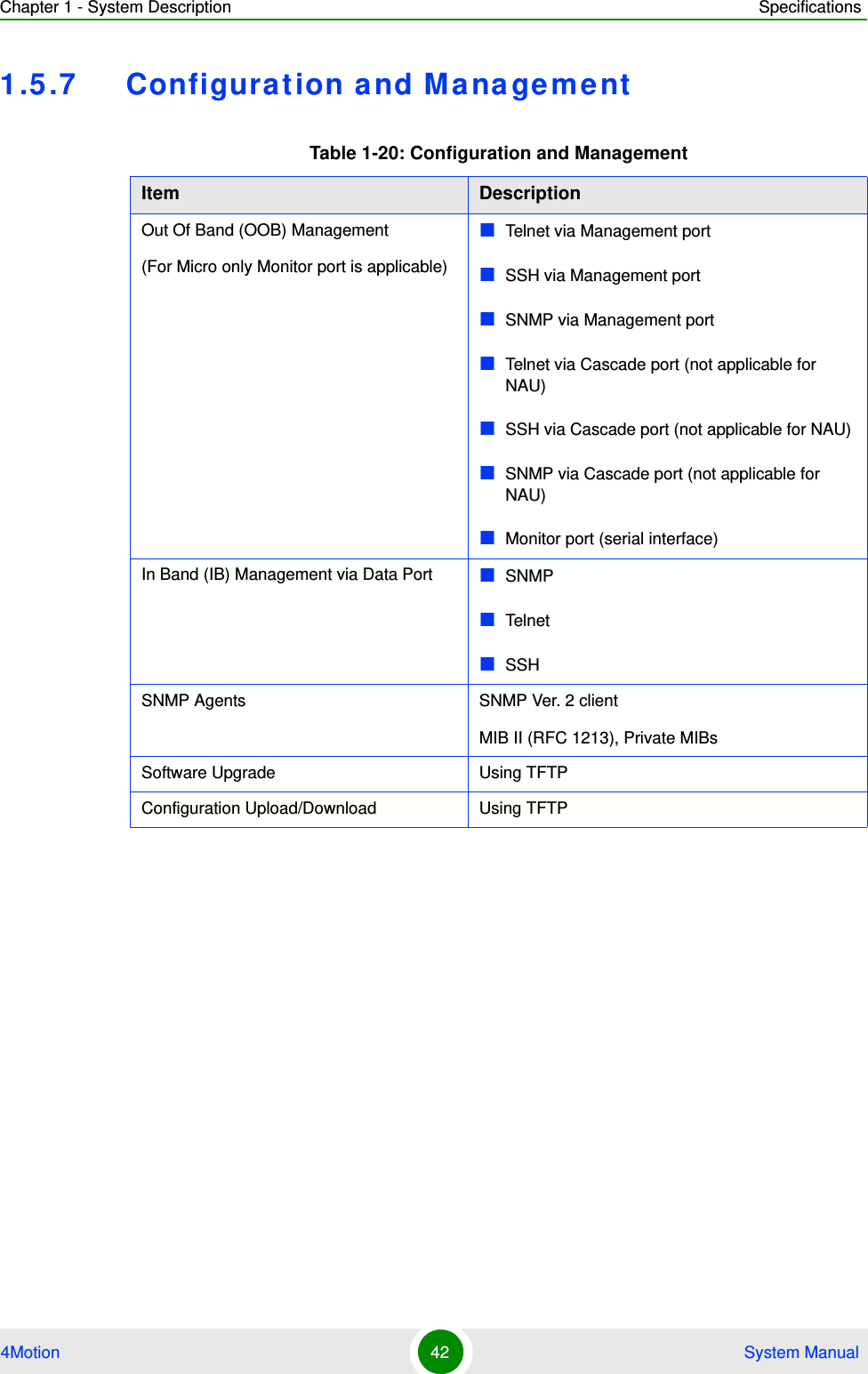
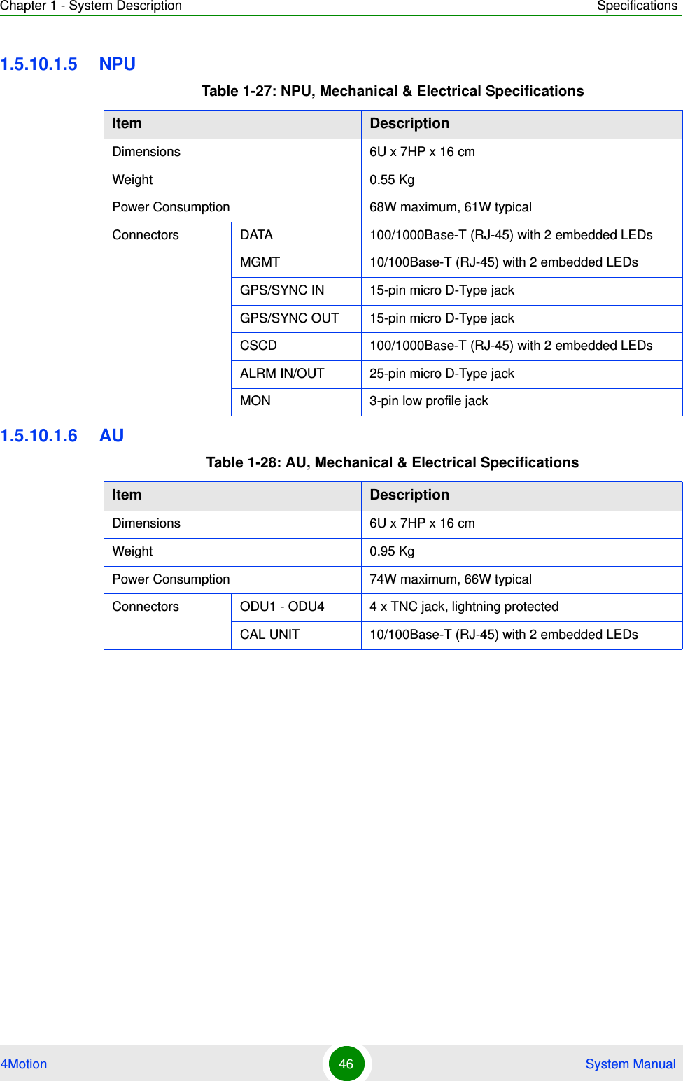
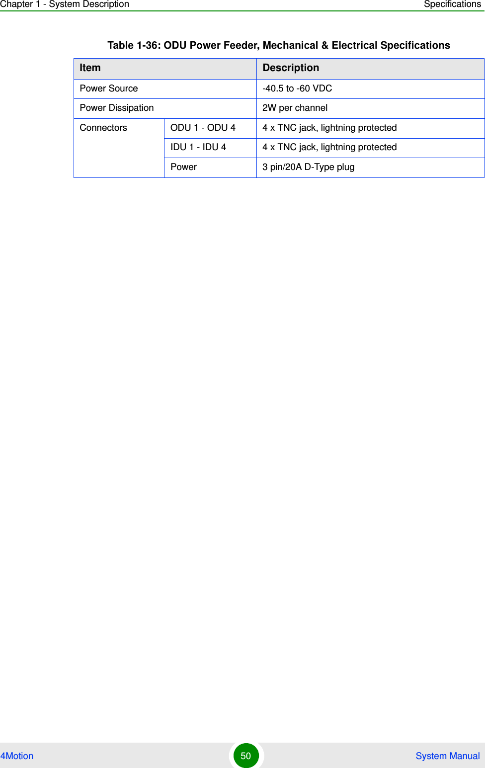

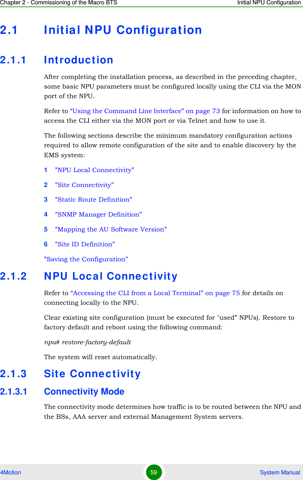
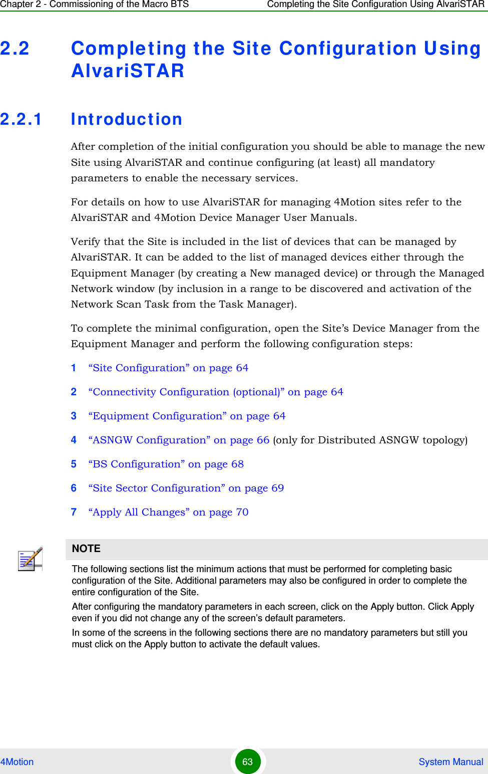
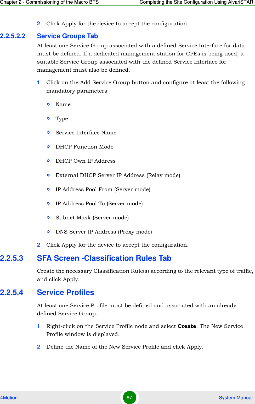
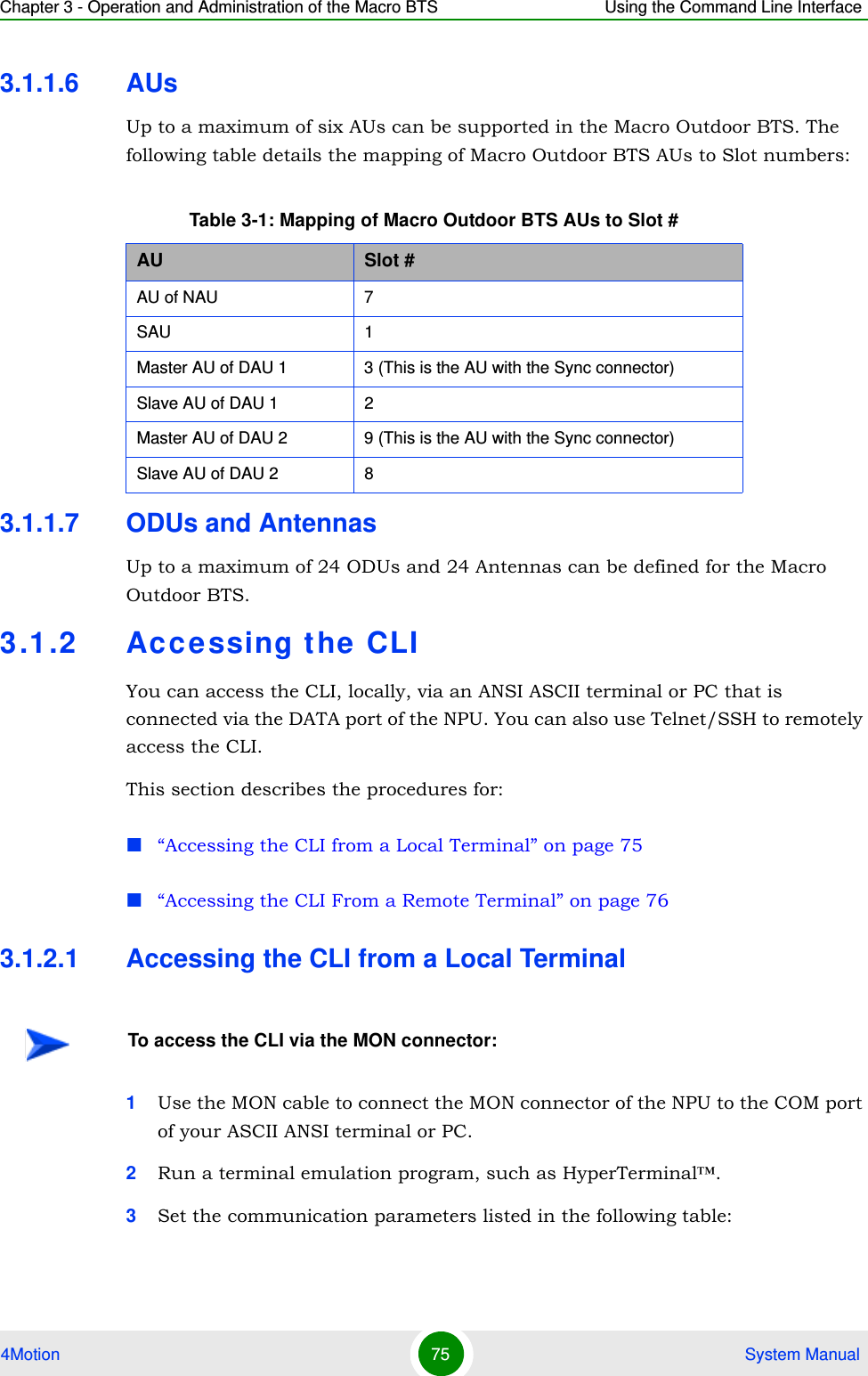
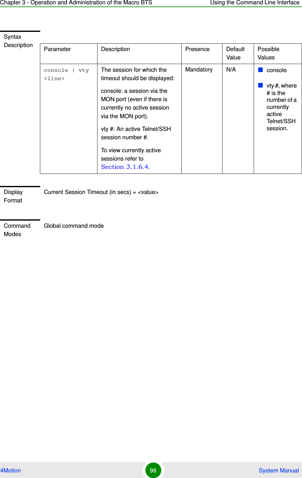
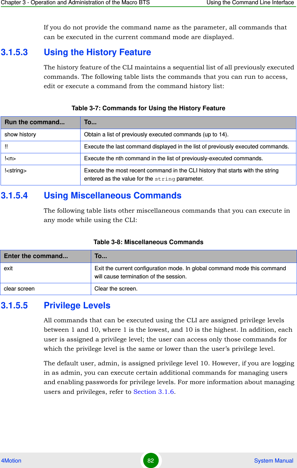
![Chapter 3 - Operation and Administration of the Macro BTS Using the Command Line Interface4Motion 79 System Manual3.1.4 Interpreting t he Command SyntaxThe following table lists the conventions used in the command syntax for all 4Motion commands:Enter the interface configuration modenpu(config)# interface {<interface-type> <interface-id> |internal-mgmt |external-mgmt | bearer | local-mgmt | npu-host | all-au}npu(config-if)# Exit the configuration mode and enter the global command mode.npu(config)# endnpu (config-if)# endnpu#npu#Exit the current configuration mode by one levelnpu (config-if)# exit npu(config)#Table 3-5: Conventions Used in the 4Motion Command SyntaxConvention Description Example{ } Indicates that the parameters enclosed in these brackets are mandatory, and only one of these parameters should be specified.npu(config)# limit {cpu | memory} ([softlimit <limit>] [hardlimit <limit>])This command is used for specifying the soft and hard limits for memory and CPU utilization. The cpu/memory parameters are enclosed within {} brackets, indicating that their presence is mandatory, and that only one of these parameters is required. ( ) Indicates that one or all parameters enclosed within these brackets are optional. However, the presence of at least one parameter is required to successfully execute this command.npu(config)# limit {cpu | memory} ([softlimit <limit>] [hardlimit <limit>])This command is used for specifying the soft and hard limits for memory and CPU utilization. The softlimit and hardlimit parameters are enclosed within () brackets, indicating that you are required to specify the value of at least one of these parameters to successfully execute this command.Table 3-4: Commands to Enter/Exit a Command Mode](https://usermanual.wiki/Alvarion-Technologies/MICRO-25.Manual-p1/User-Guide-1329242-Page-128.png)
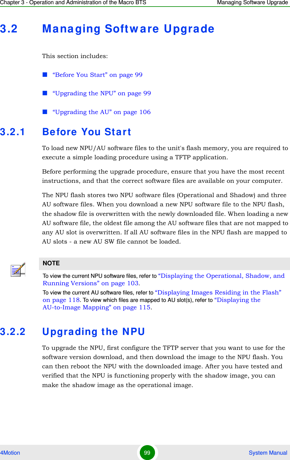
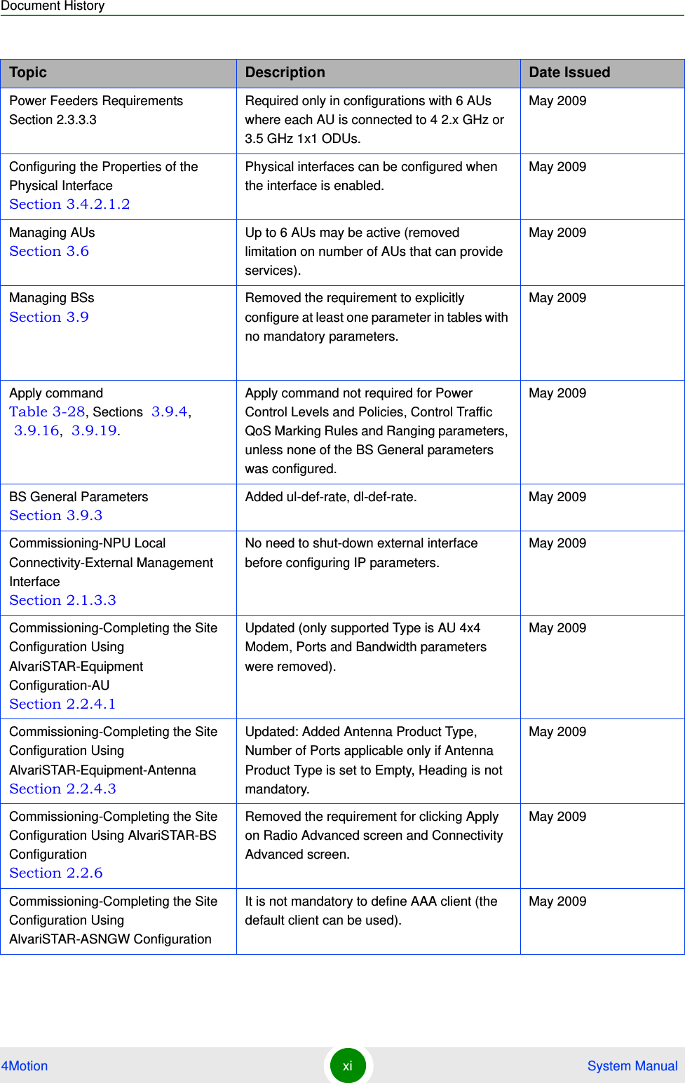
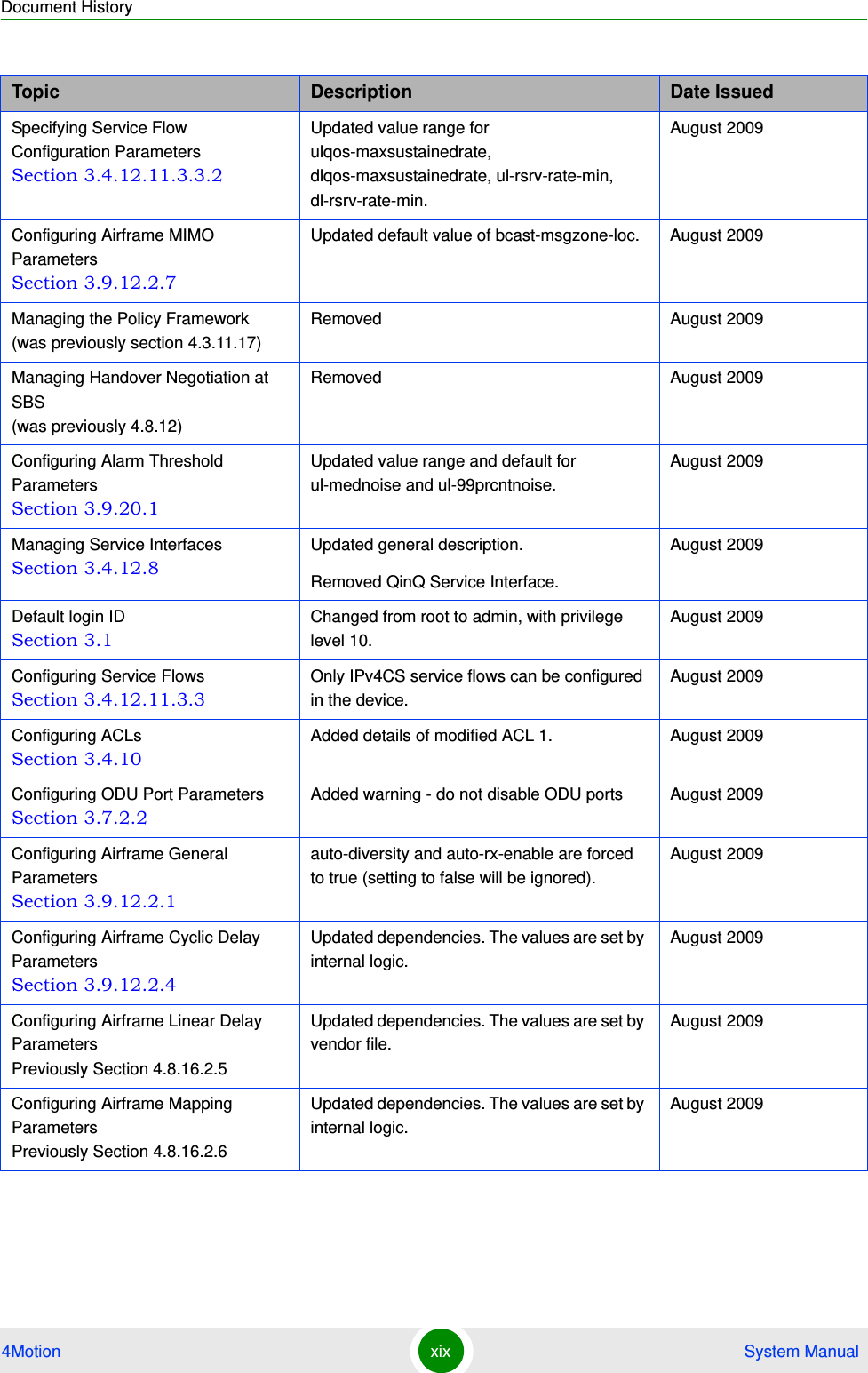
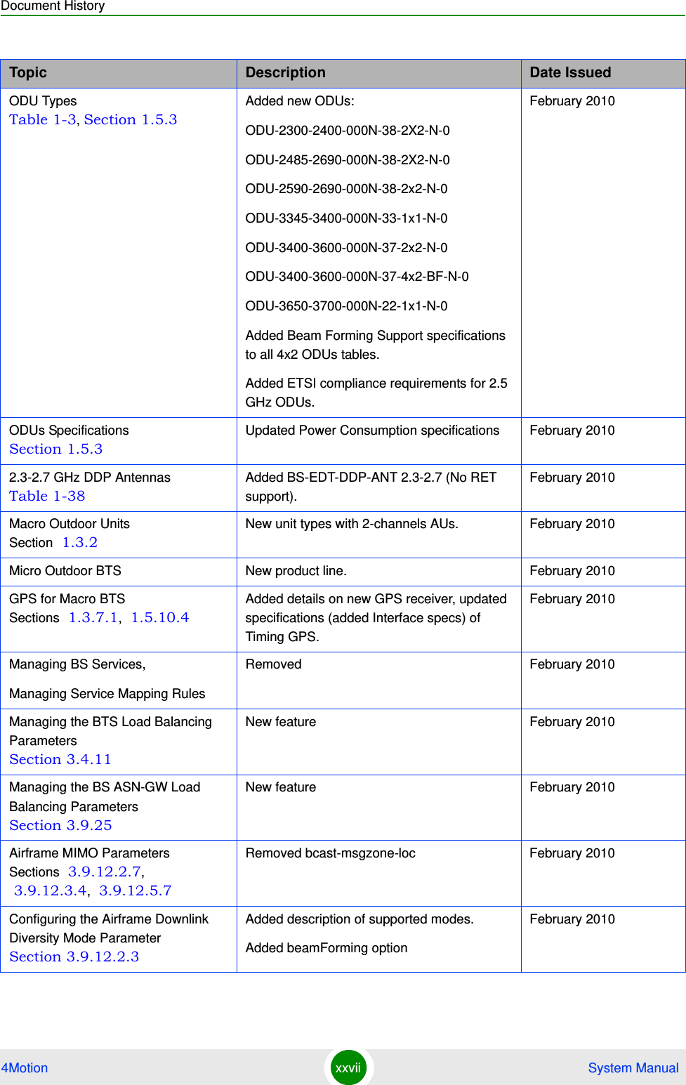
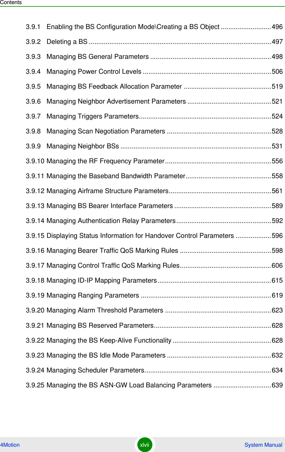
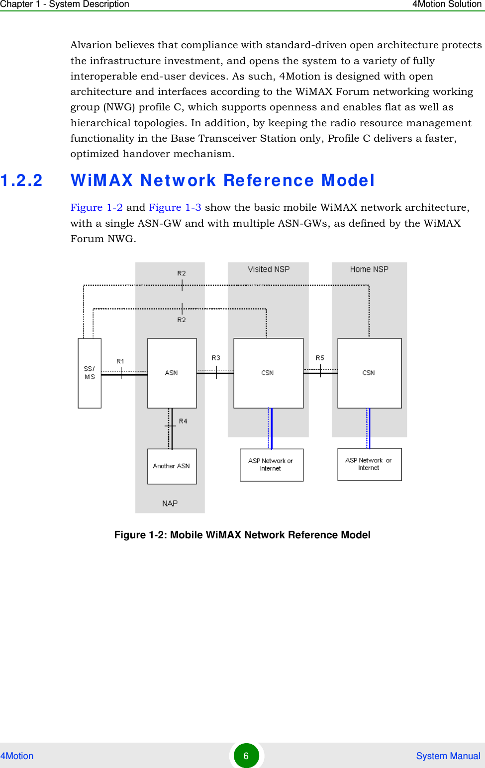
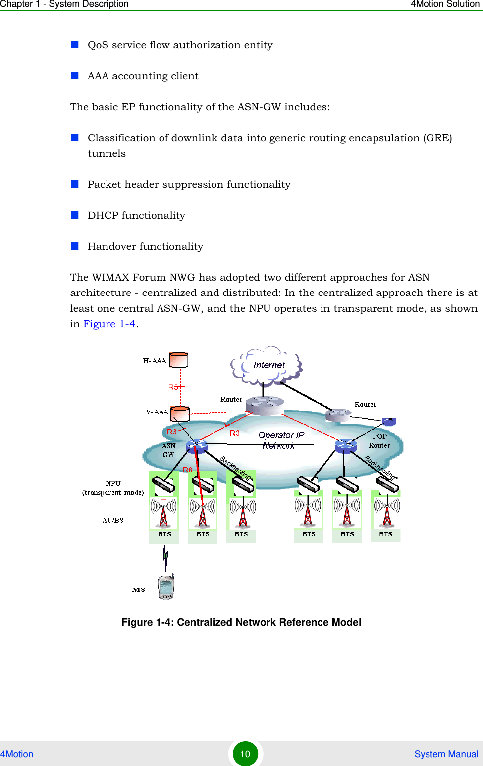
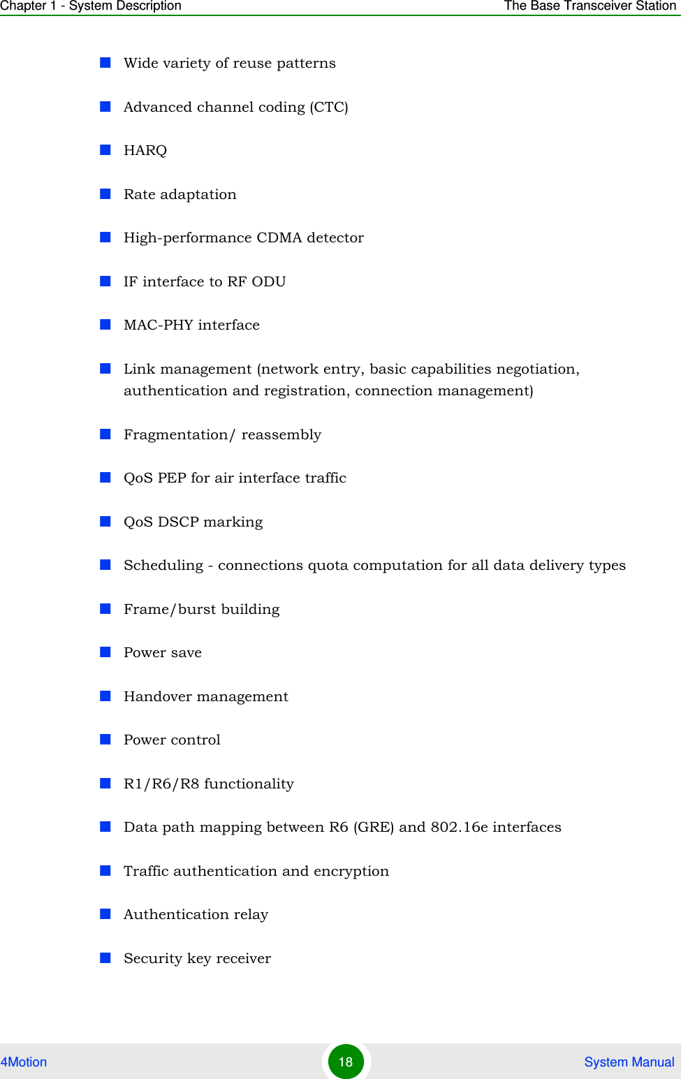
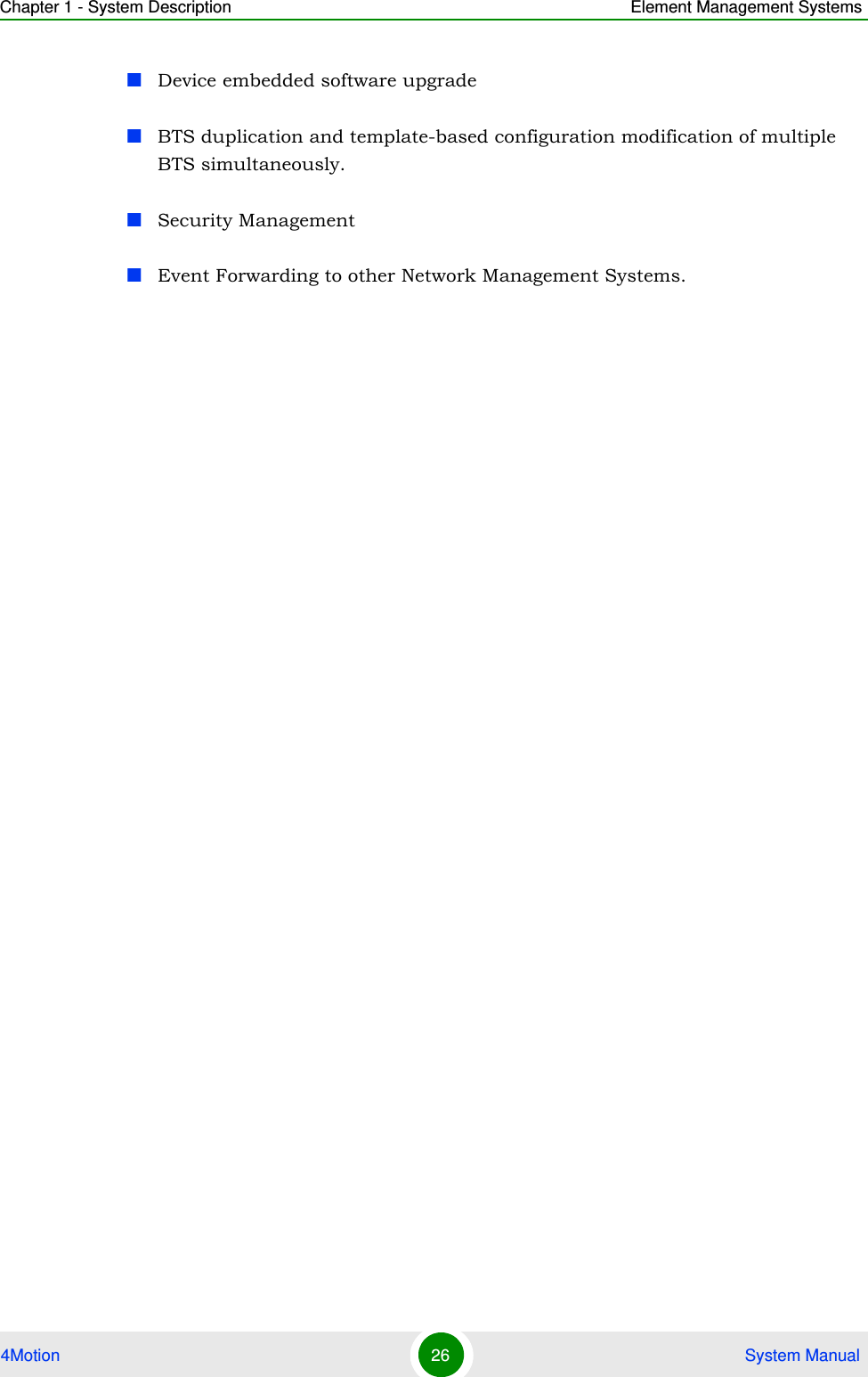
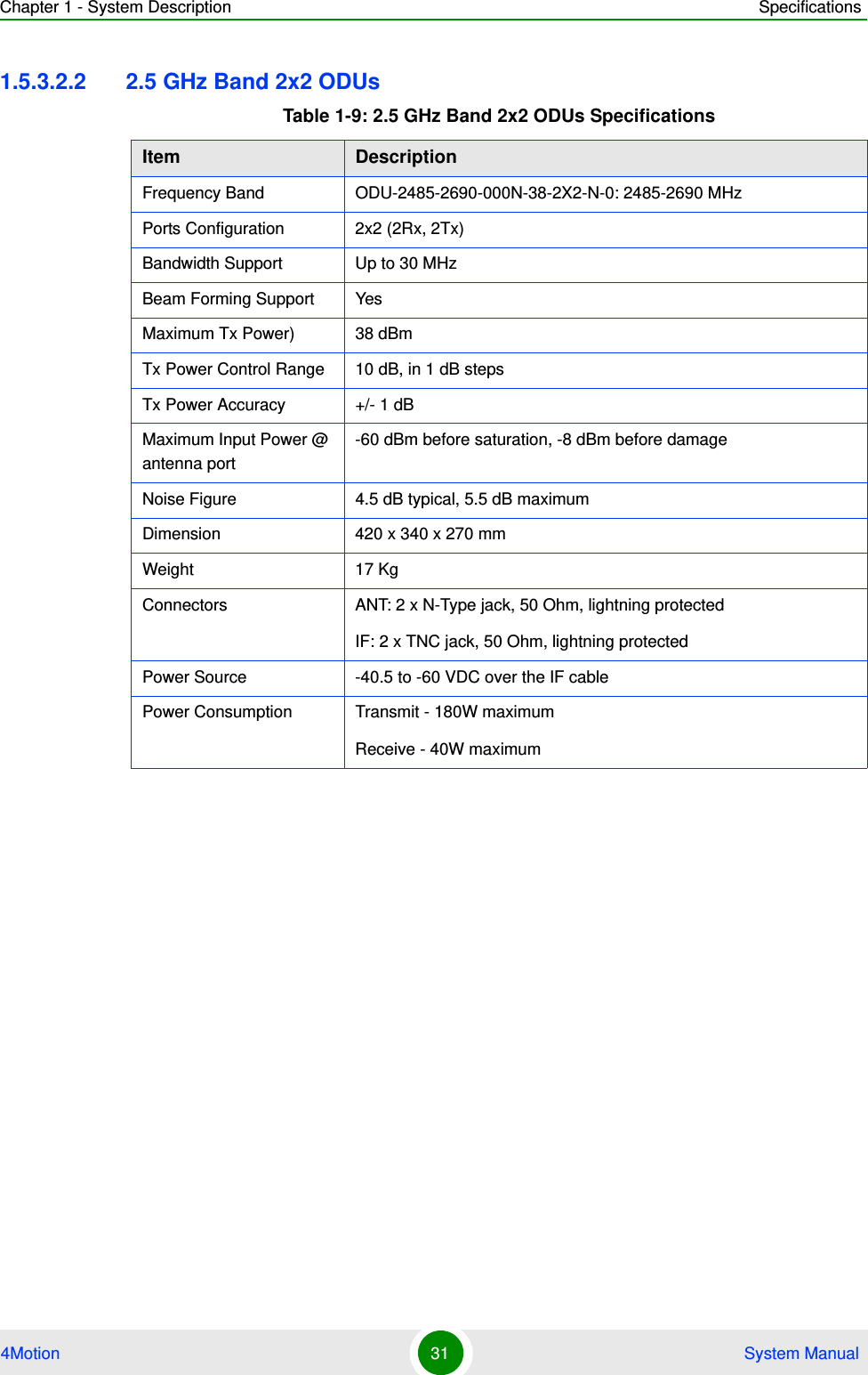
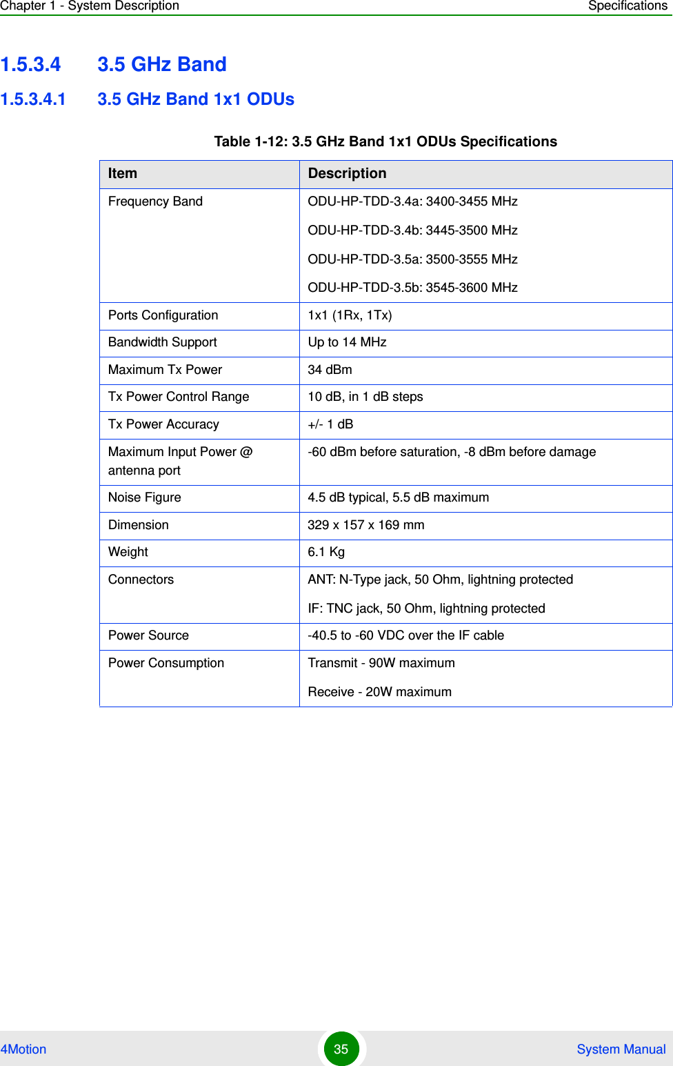
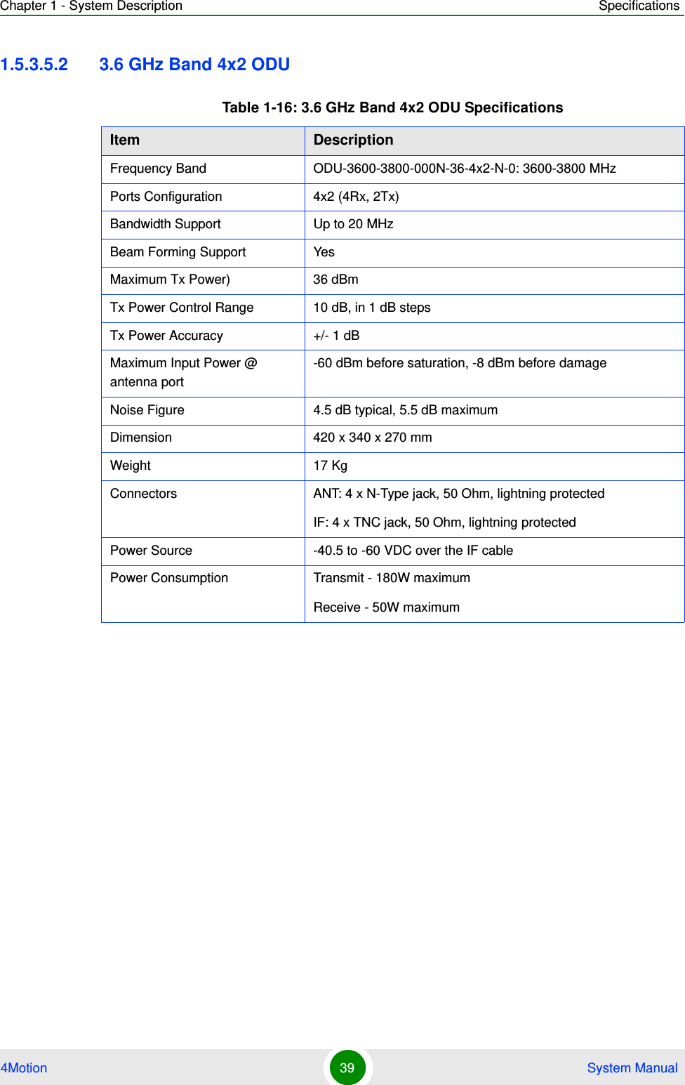
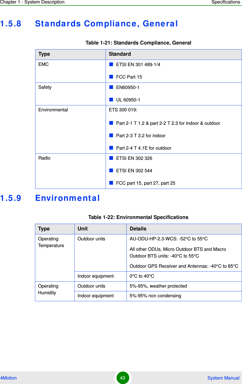
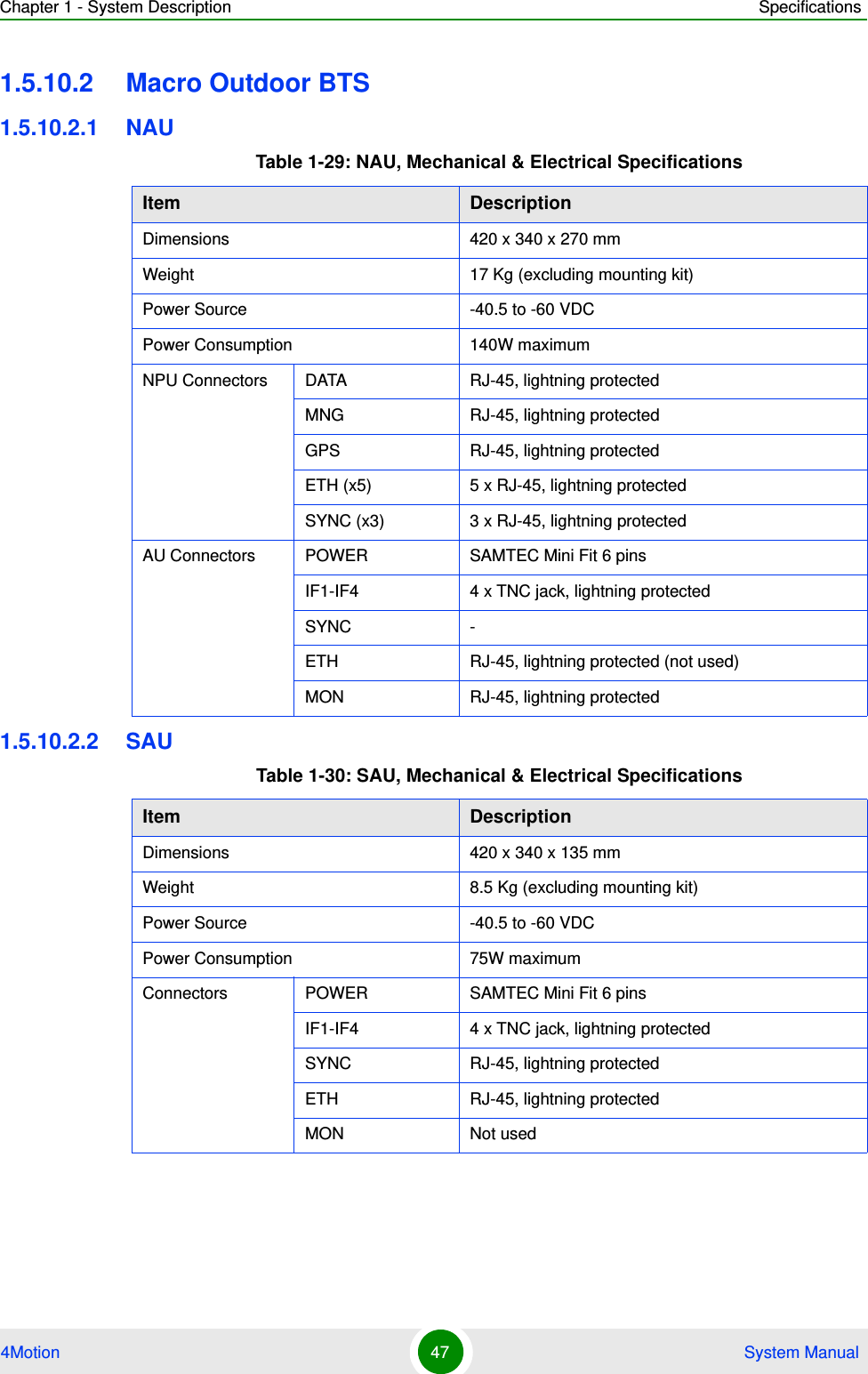
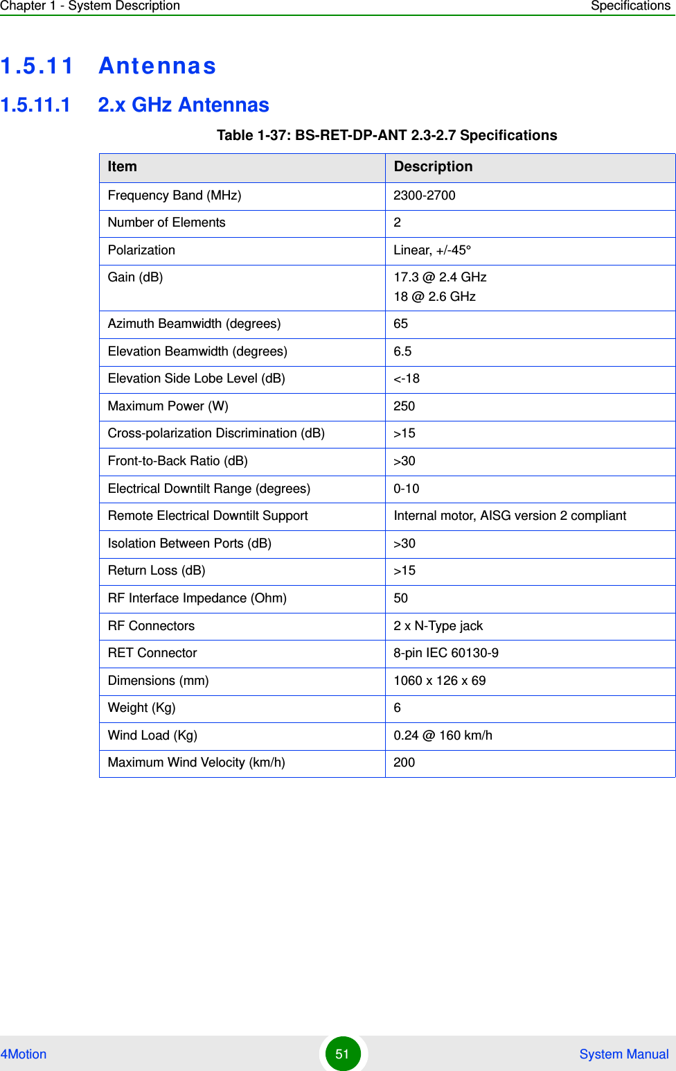
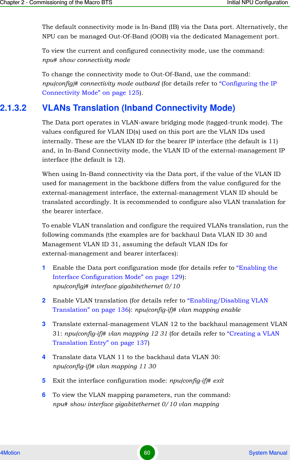
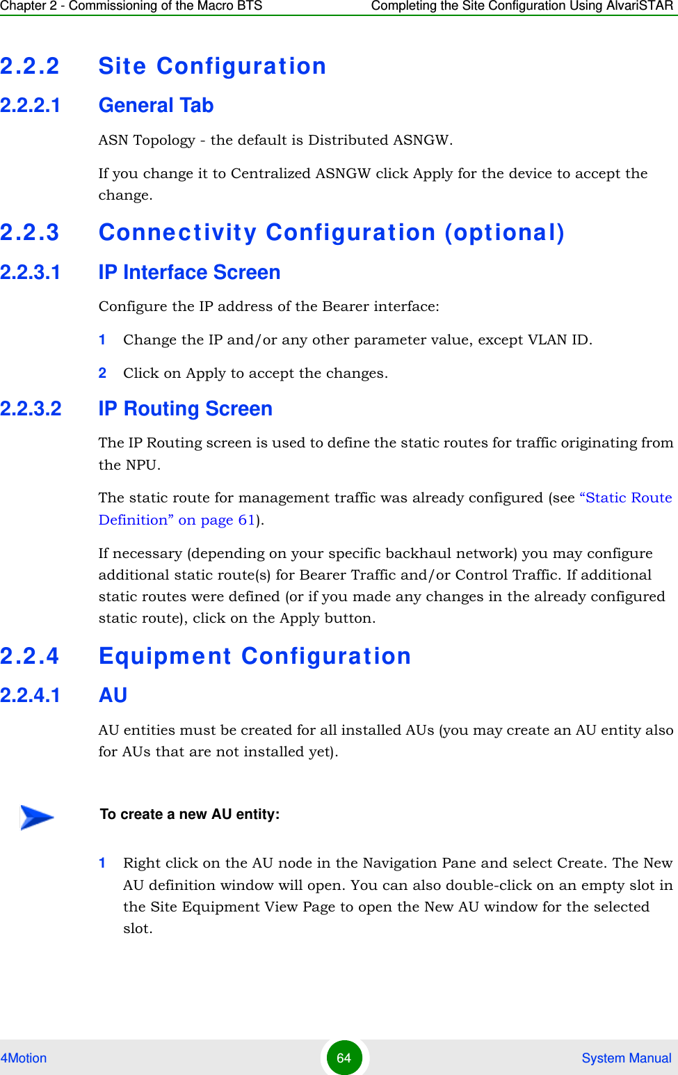
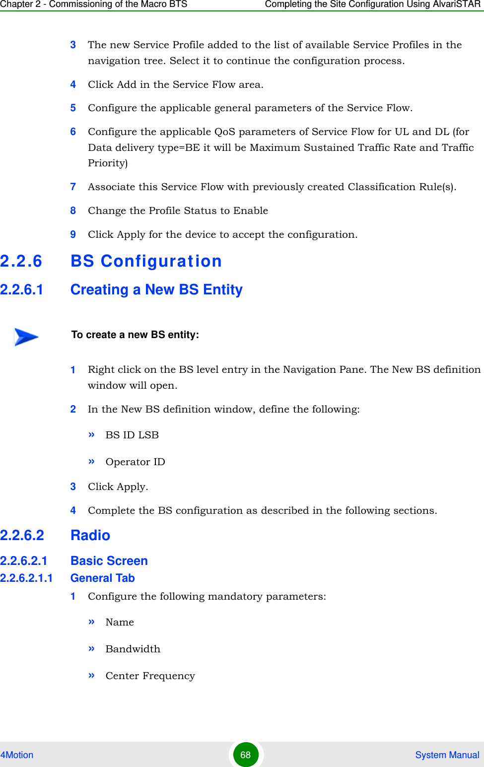
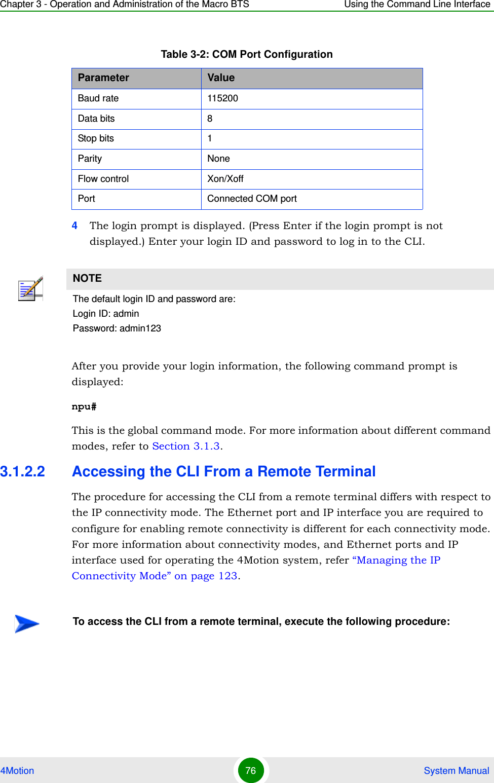
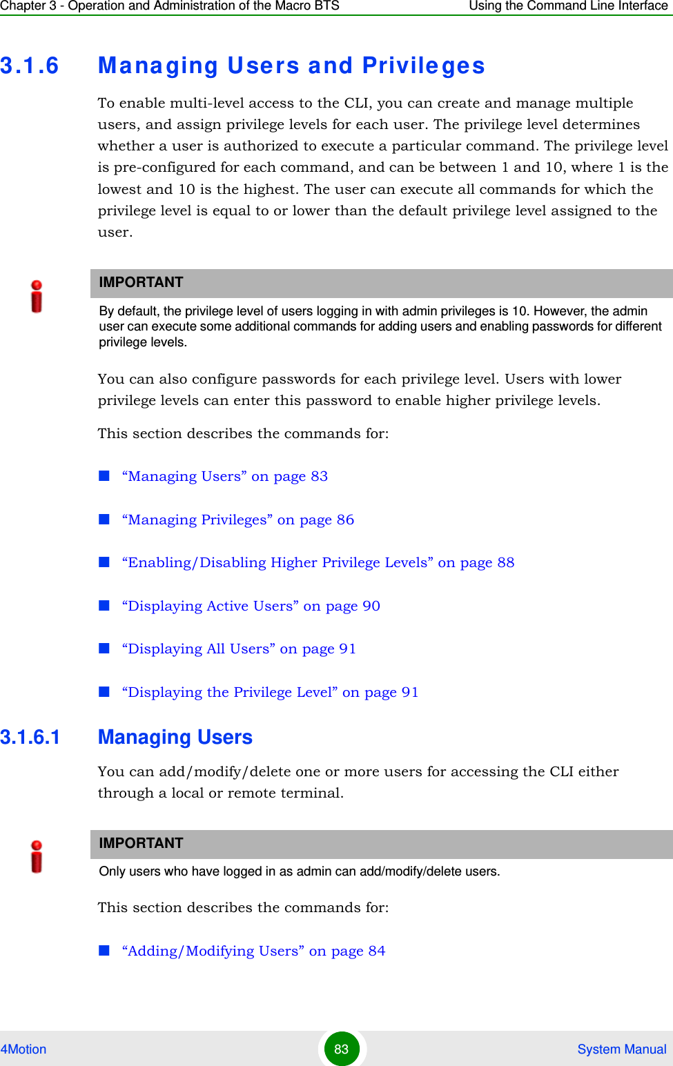
![Chapter 3 - Operation and Administration of the Macro BTS Using the Command Line Interface4Motion 80 System Manual3.1.5 Using the CLITo help you use the CLI, this section provides information about:“Using Control Characters” on page 81“Using the CLI Help” on page 81“Using the History Feature” on page 82[ ] Indicates that the parameter enclosed within these brackets is optional.npu(config)# reboot from shadow [<shadow image name>]This command is used to reboot the system with the shadow image. The shadow image name parameter is enclosed with the [ ] brackets, indicating that it is optional. If you do not specify the value of this parameter, the system automatically boots up with the last downloaded shadow image.< > Indicates that the parameter is mandatory and requires a user-defined value (and not a discrete value).npu(config)# load to shadow <shadow image name>This command is used to load the system with a particular shadow image. It is mandatory to specify a value for the shadow image name parameter; otherwise an error is raised by the system. The value of this parameter is not a discrete value; you are required to specify a value for this parameter.| Indicates the OR conditional operator that is used between two or more parameters. The presence of this parameter indicates that only one of the parameters separated by the I conditional parameter should be specified in the command.npu(config)# pm-group enable npu {R6InterfaceTotal | R6InterfaceBs | ProvisionedQOS | R3Interface | LoadBalancing | InitialNe | ServiceFlow}This command is used to specify the group for which performance data collection and storage is to be enabled. The | conditional operator indicates that only one parameter should be specified.NOTEIn this document, all discrete values are specified in boldface, and all user-defined values are not bold.Table 3-5: Conventions Used in the 4Motion Command Syntax](https://usermanual.wiki/Alvarion-Technologies/MICRO-25.Manual-p1/User-Guide-1329242-Page-129.png)
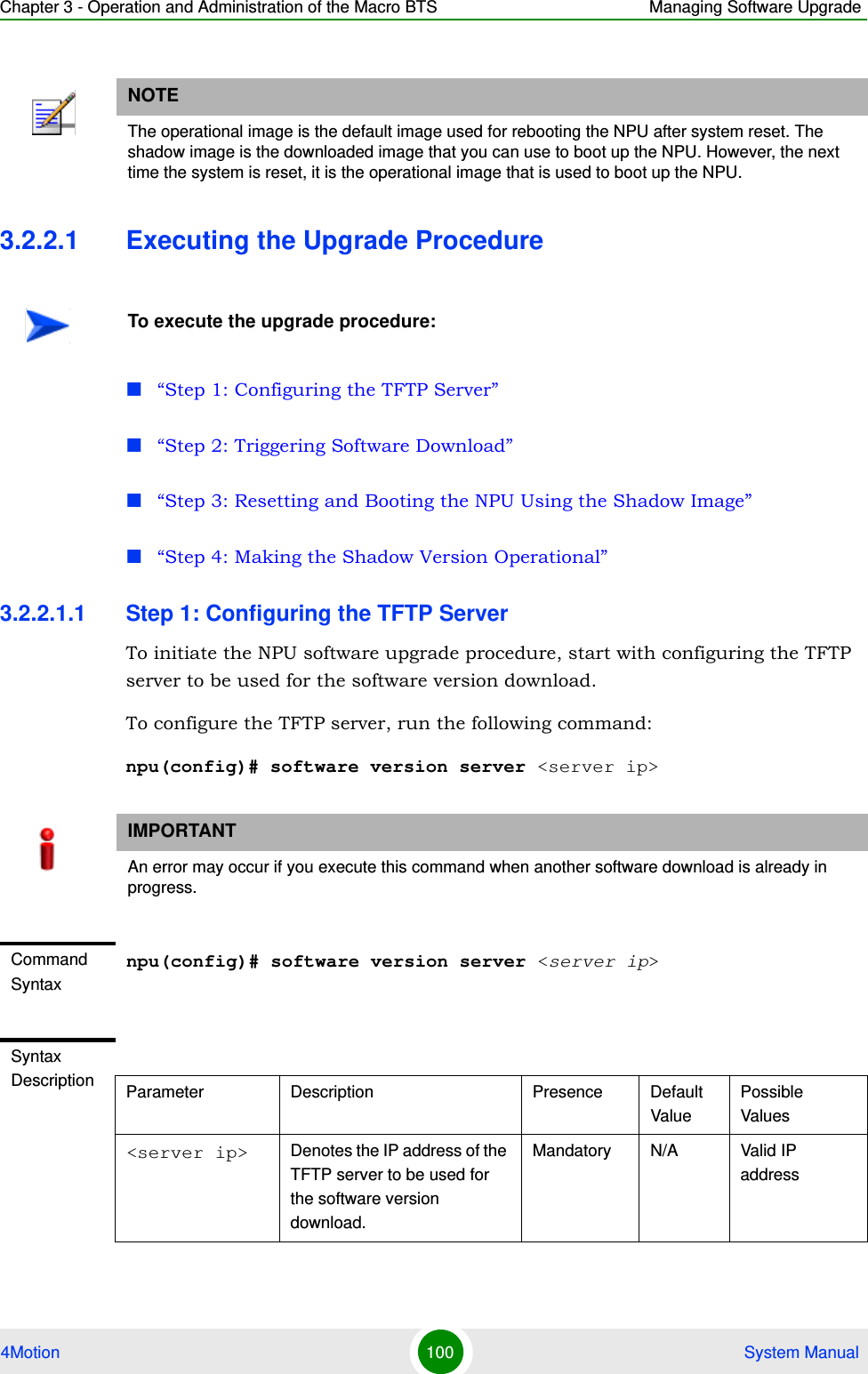
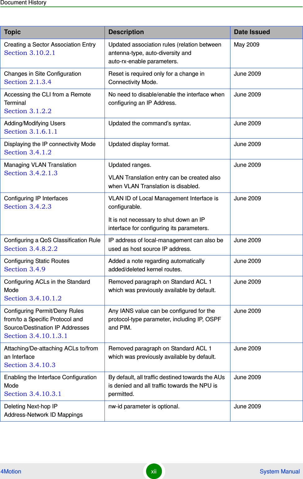
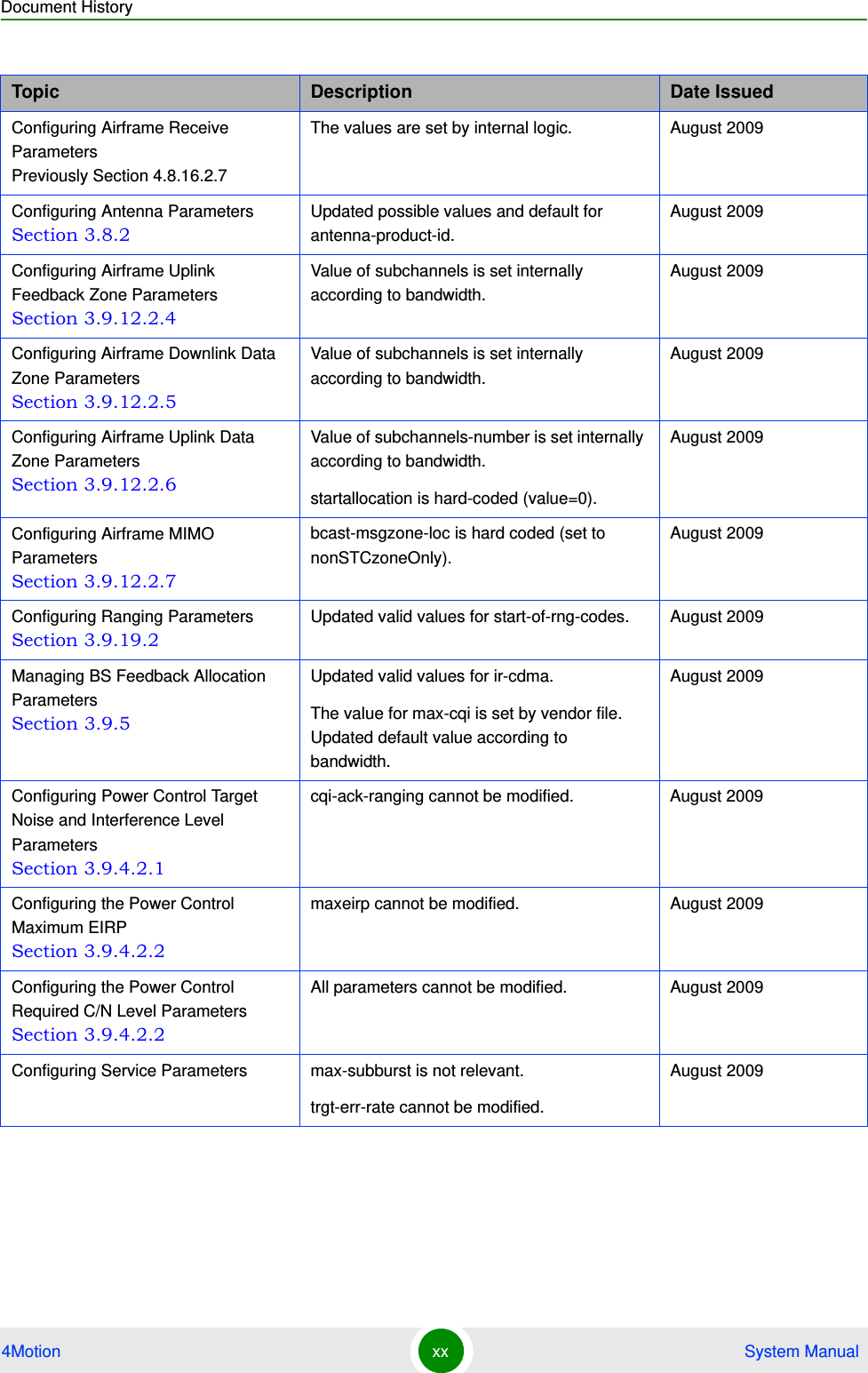
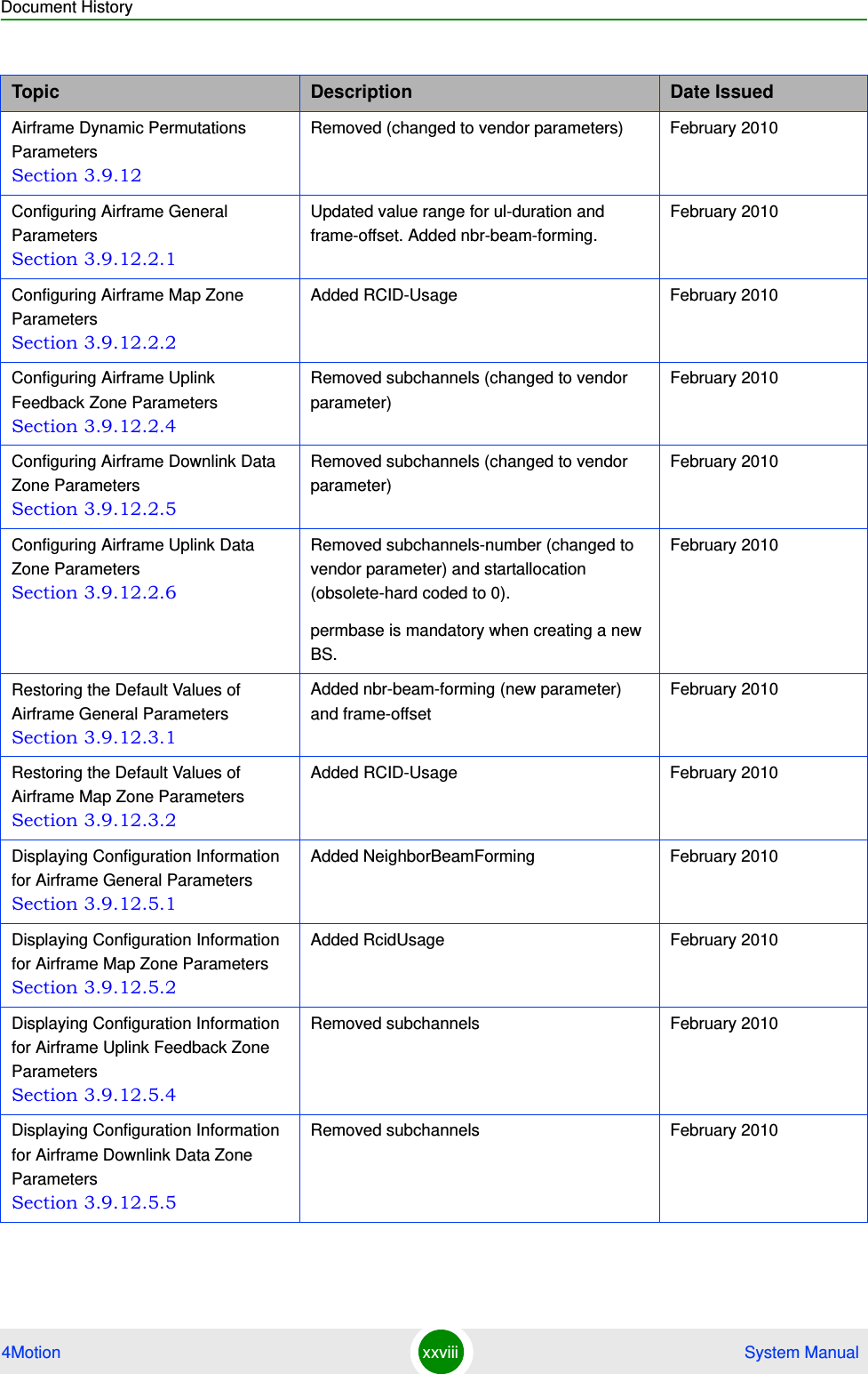
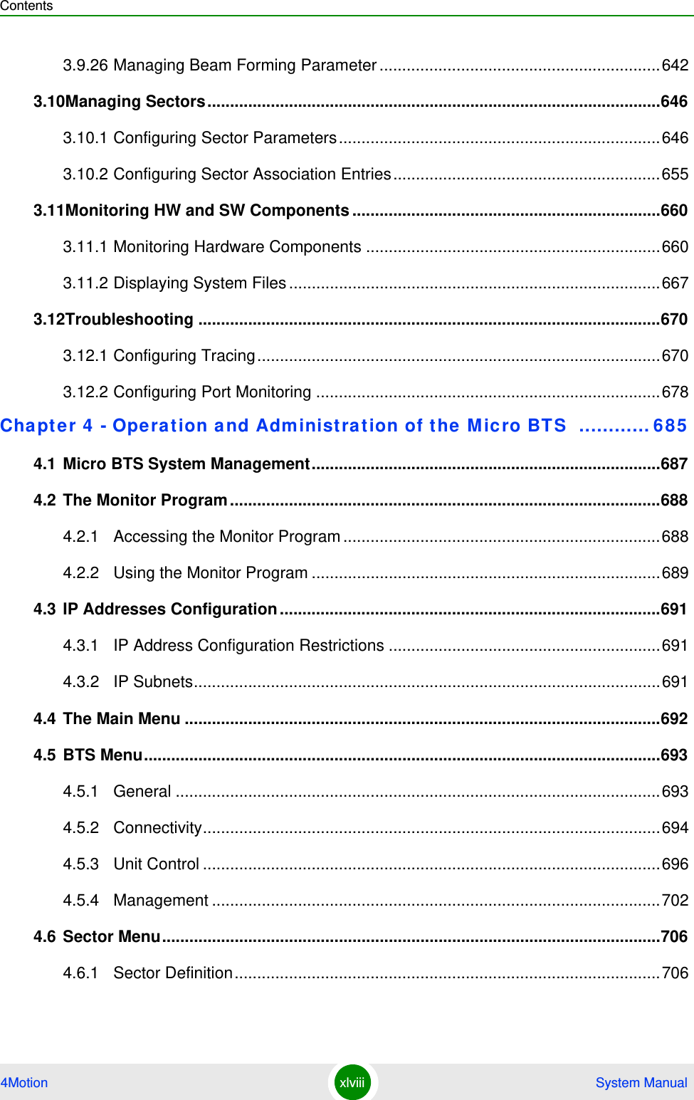
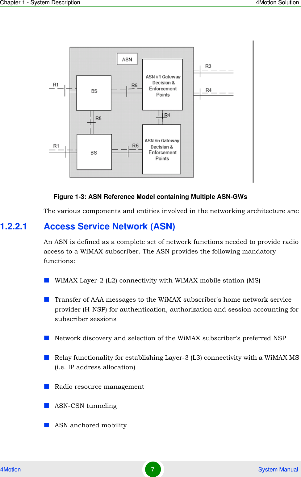
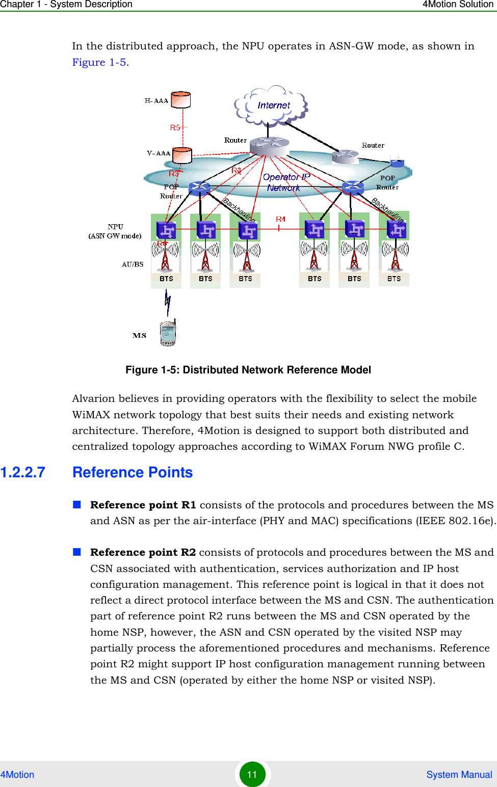
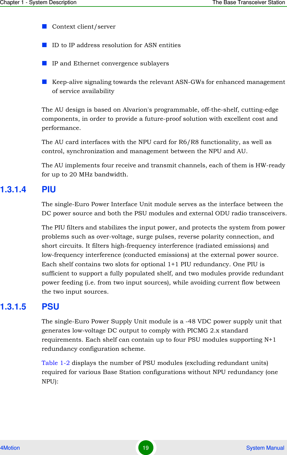
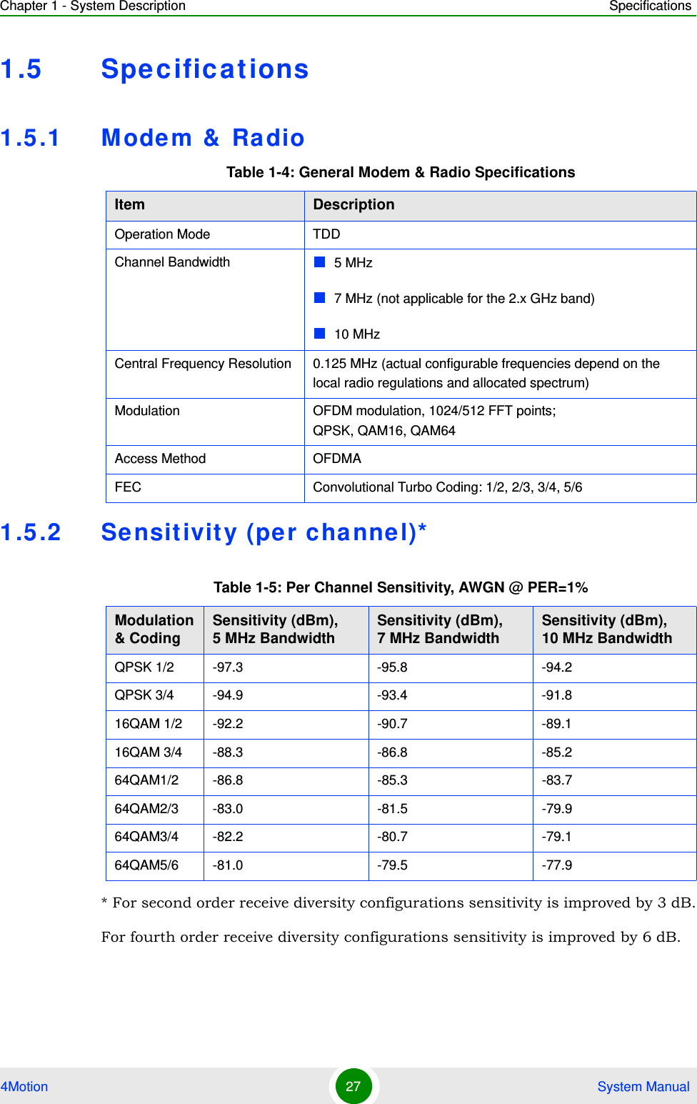
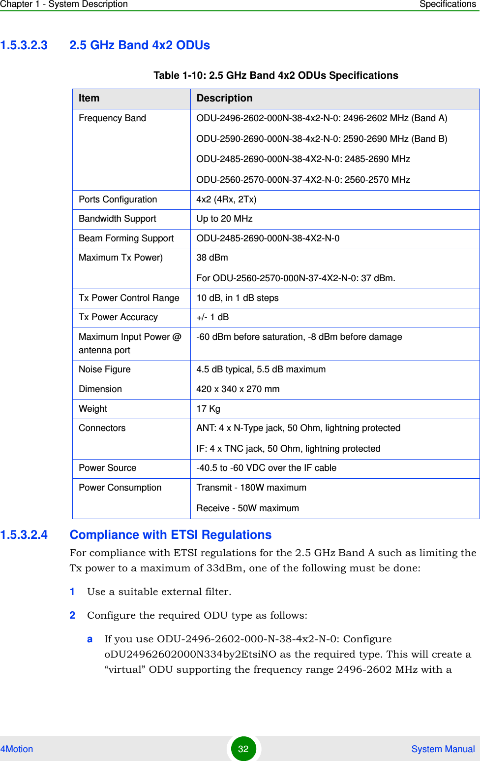
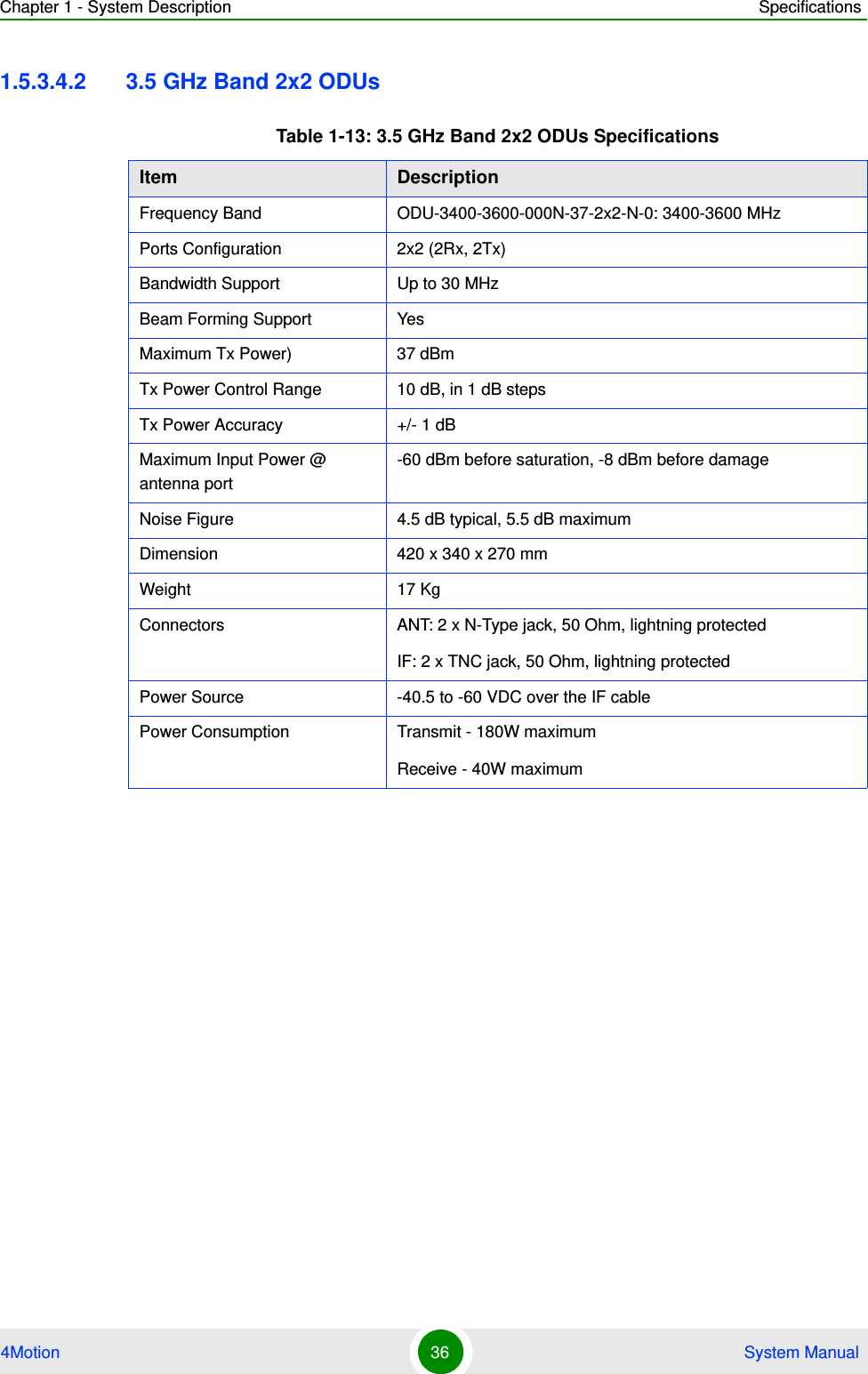
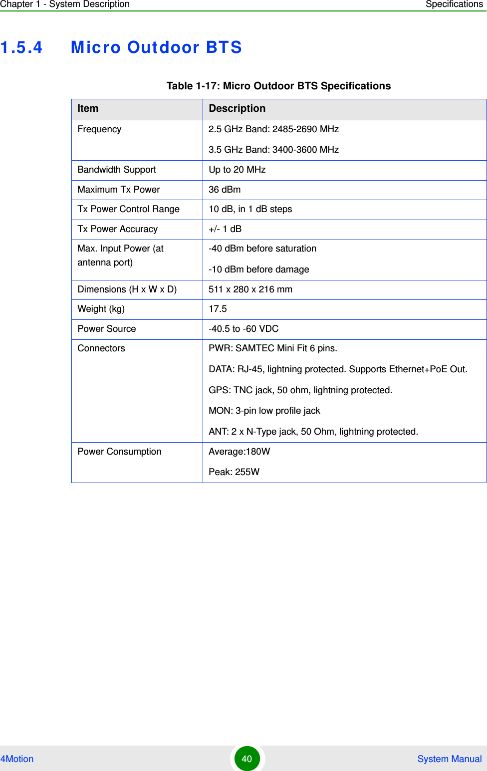
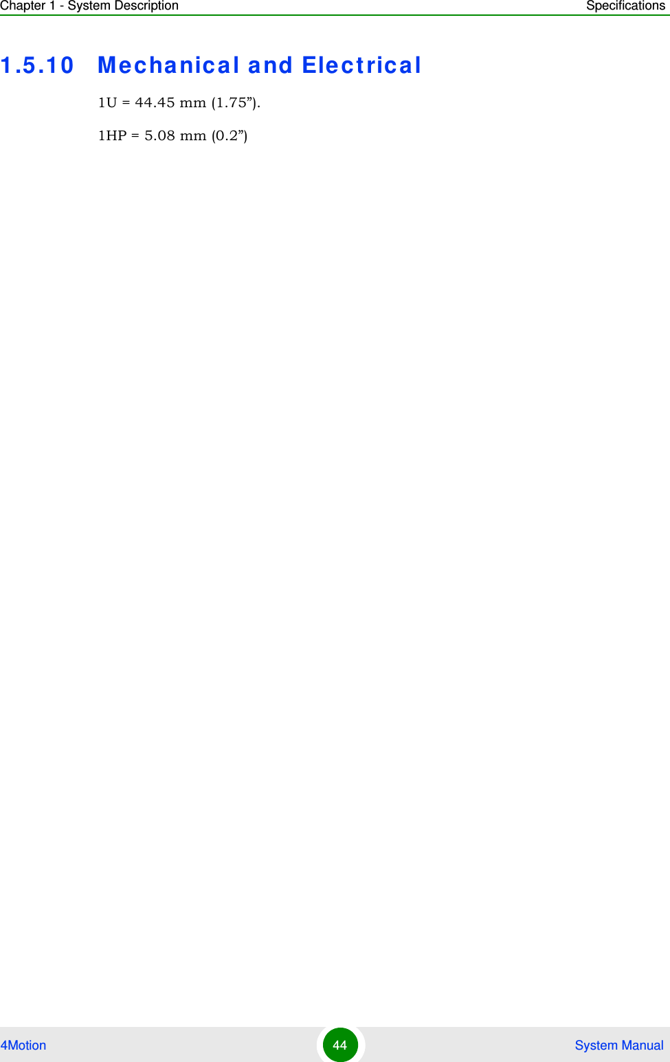
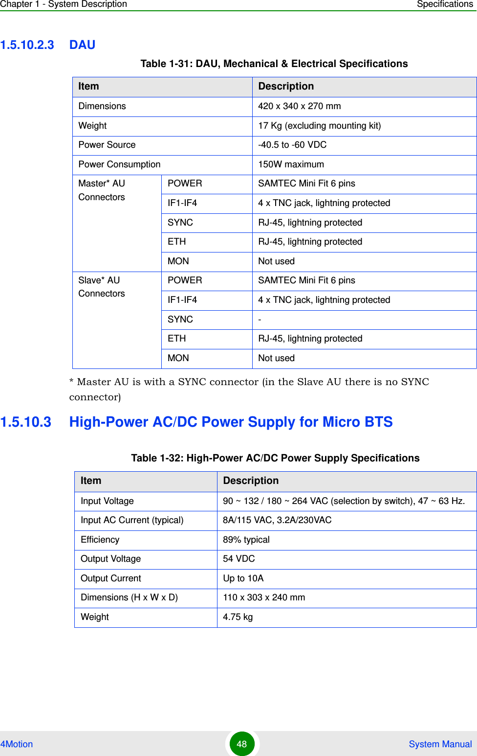
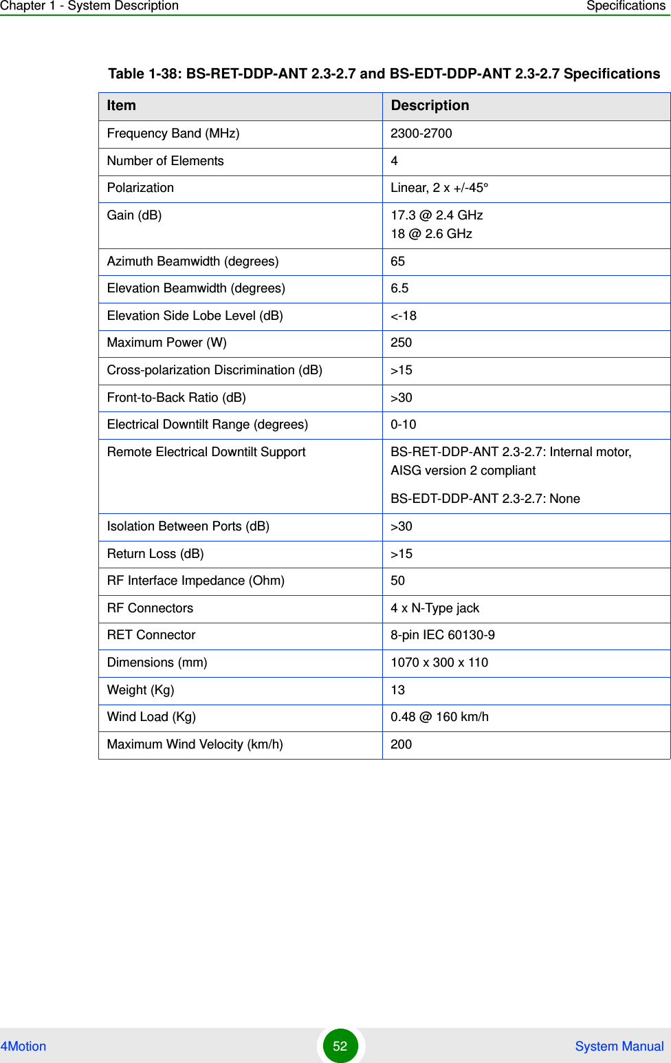
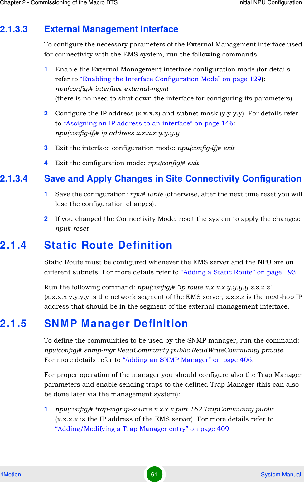
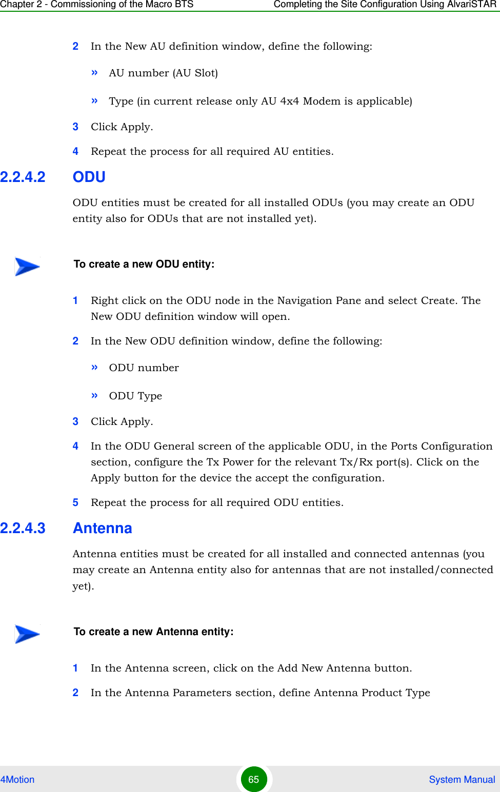
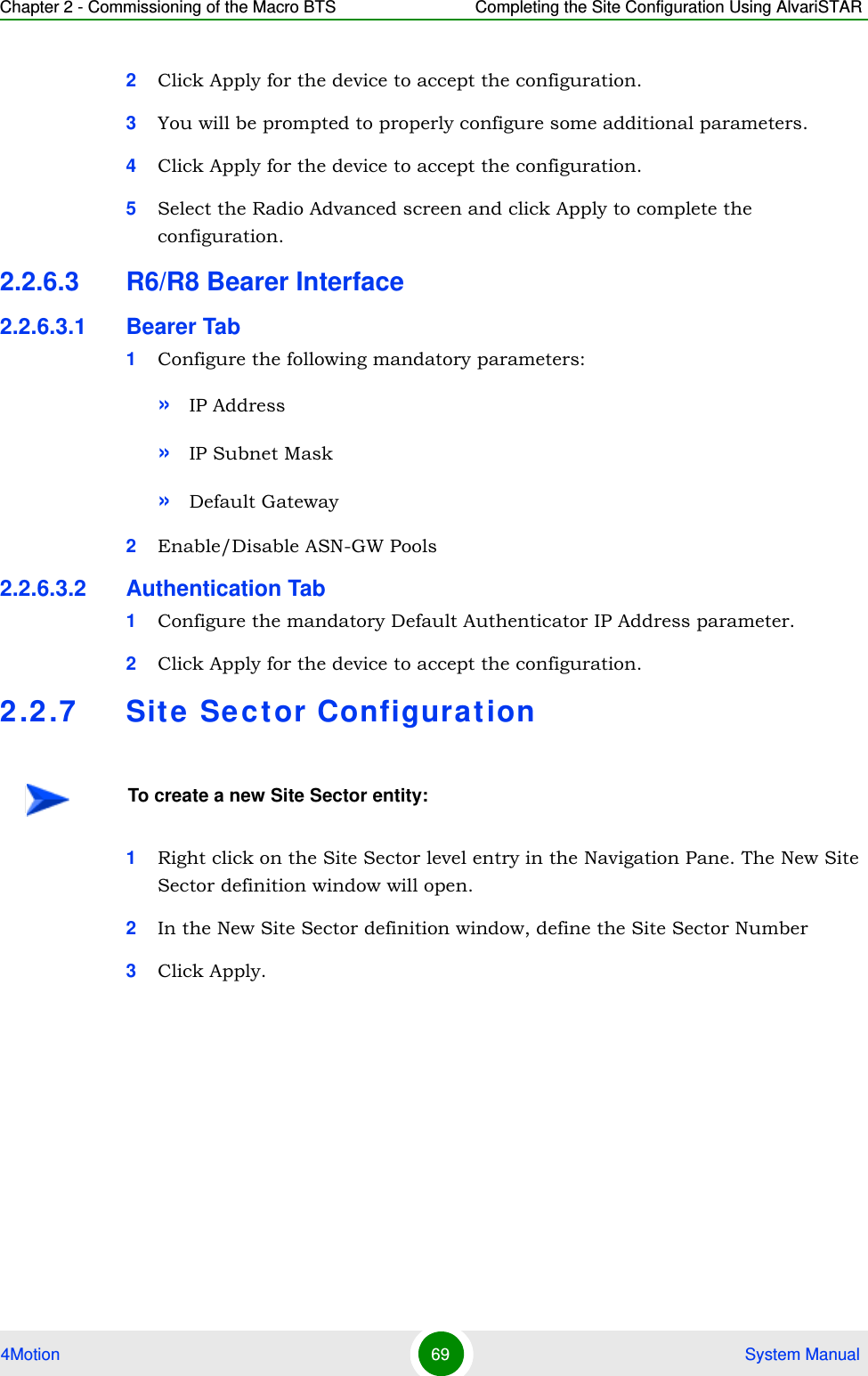
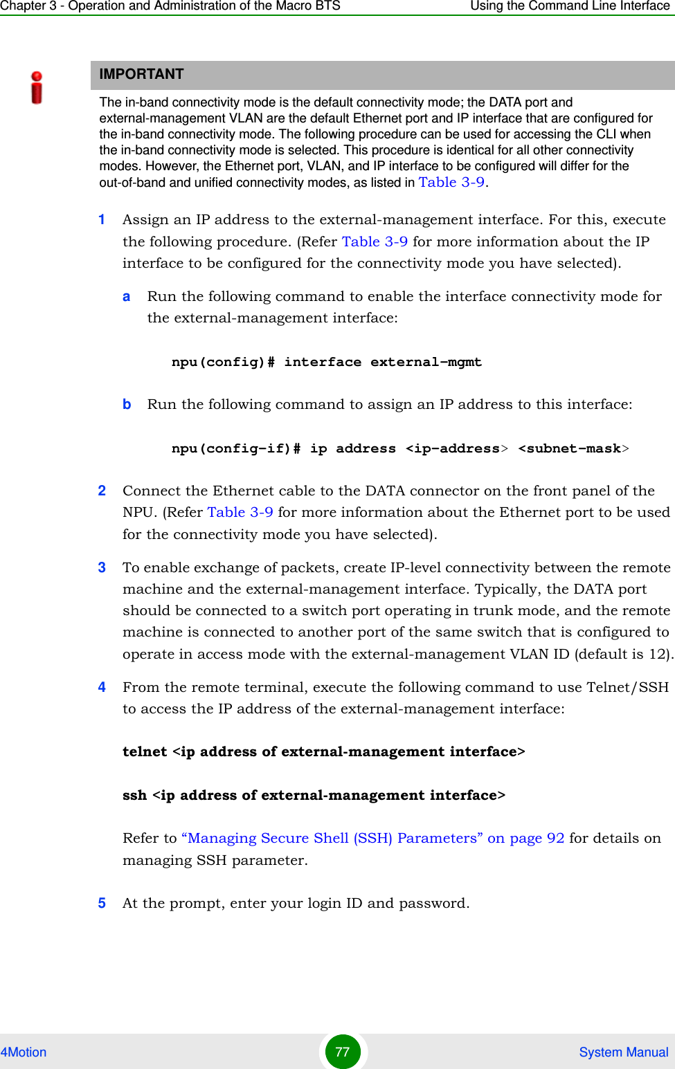
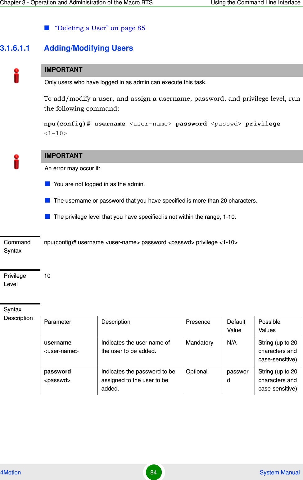
![Chapter 3 - Operation and Administration of the Macro BTS Using the Command Line Interface4Motion 81 System Manual“Using Miscellaneous Commands” on page 82“Privilege Levels” on page 823.1.5.1 Using Control CharactersControl characters refer to special characters that you can use to recall or modify previously-executed commands. The following table lists the control characters to be used for executing commands on the CLI:3.1.5.2 Using the CLI HelpThe CLI provides help that you can access while using the CLI. Execute the following command to obtain help for a specific command:help [“<text>”]Specify the command name as the parameter to view help for this command. For example, to obtain help for the show resource limits command, run the following command:npu# help “show resource limits”The help for the show resource limits command is displayed. Table 3-6: Control Characters for Using the CLIPress To...Up/Down arrow keys Scroll the previously executed CLI commands. Press Enter if you want to select and execute a particular command.Right/Left arrow keys Navigate to the right/left of the selected character in a command.Home key Navigate to the first character of a command.End key Navigate to the last character of a command.Backspace key Delete the characters of a command.TAB key Prompt the CLI to complete the command for which you have specified a token command. Remember that the CLI that is the nearest match to the token command that you have specified is displayed.? key View the list of commands available in the current mode. If you press ? after a command, a list of parameters available for that command is displayed.](https://usermanual.wiki/Alvarion-Technologies/MICRO-25.Manual-p1/User-Guide-1329242-Page-130.png)
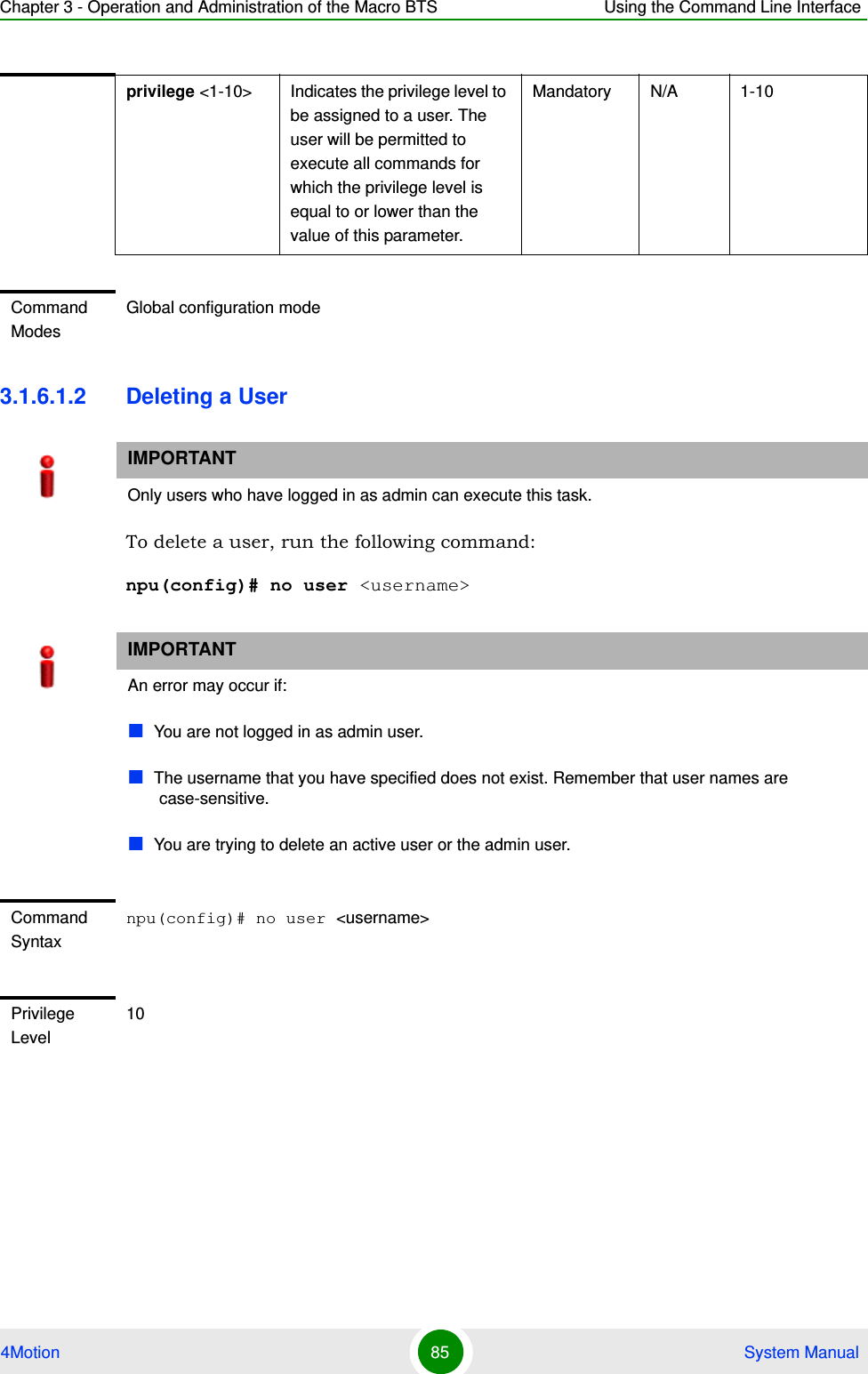
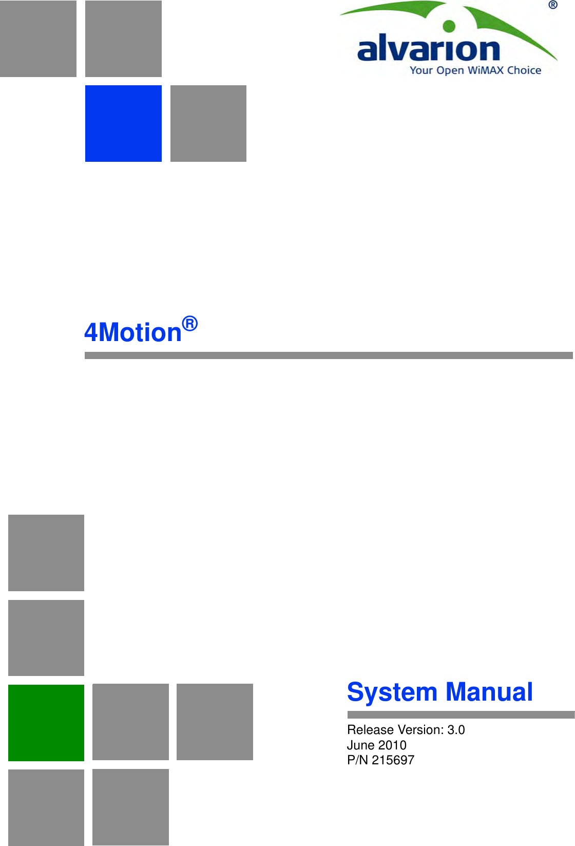
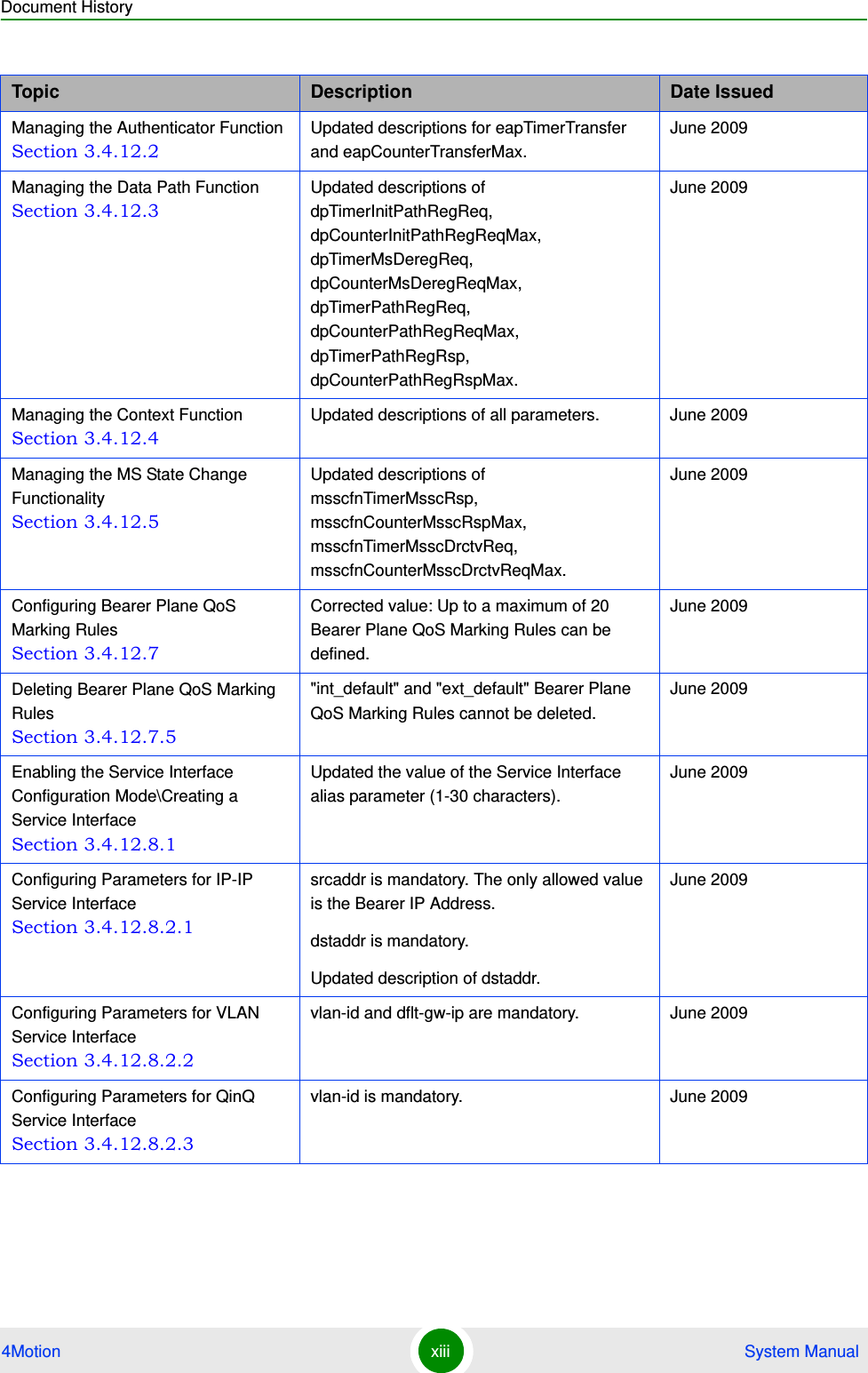
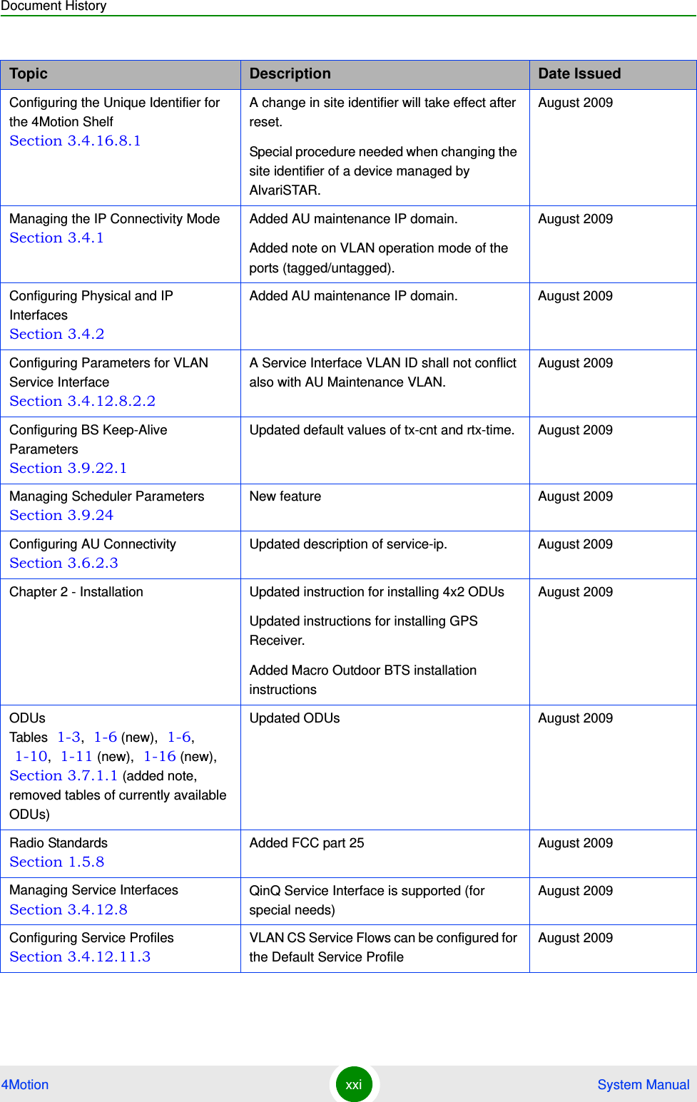
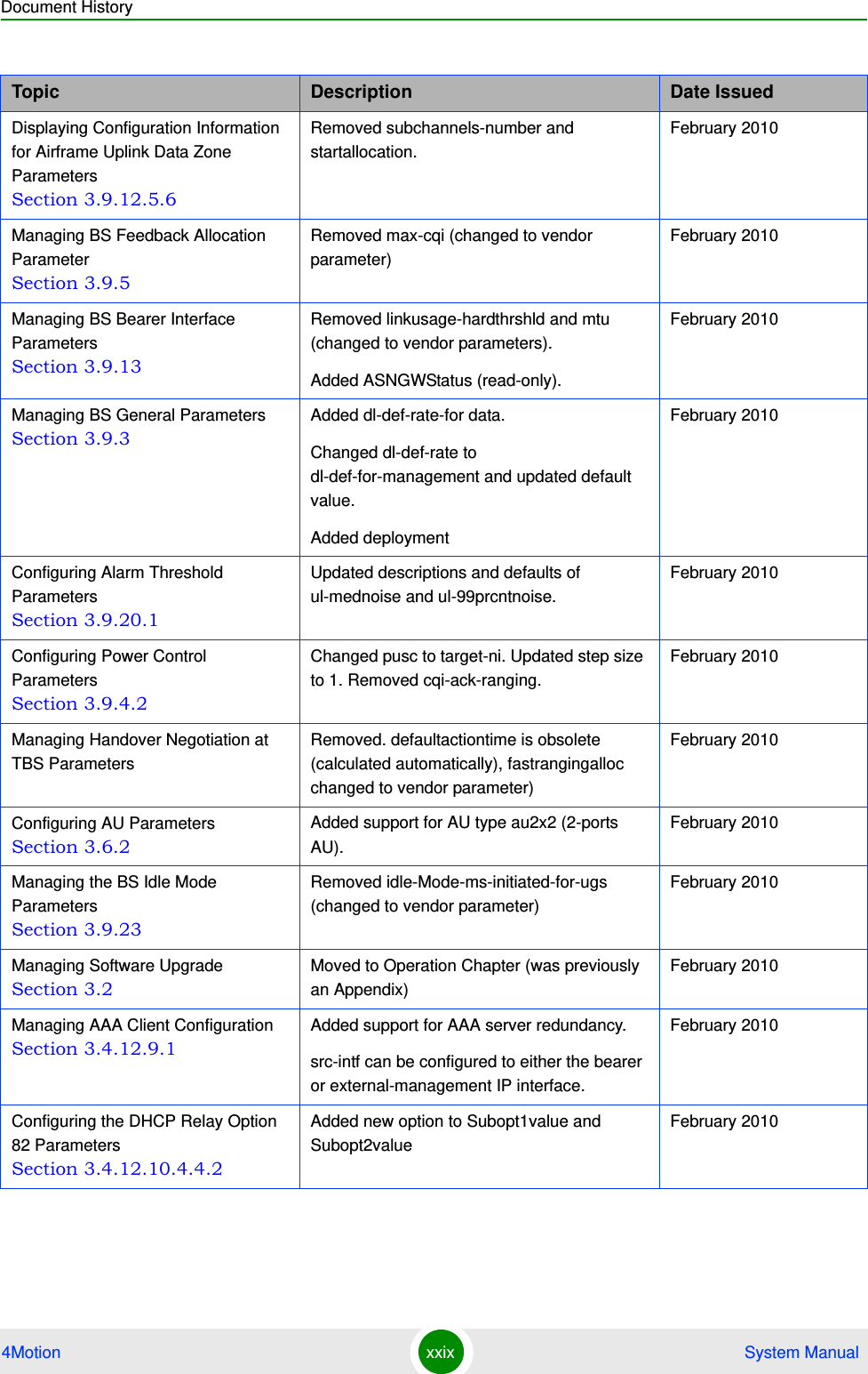
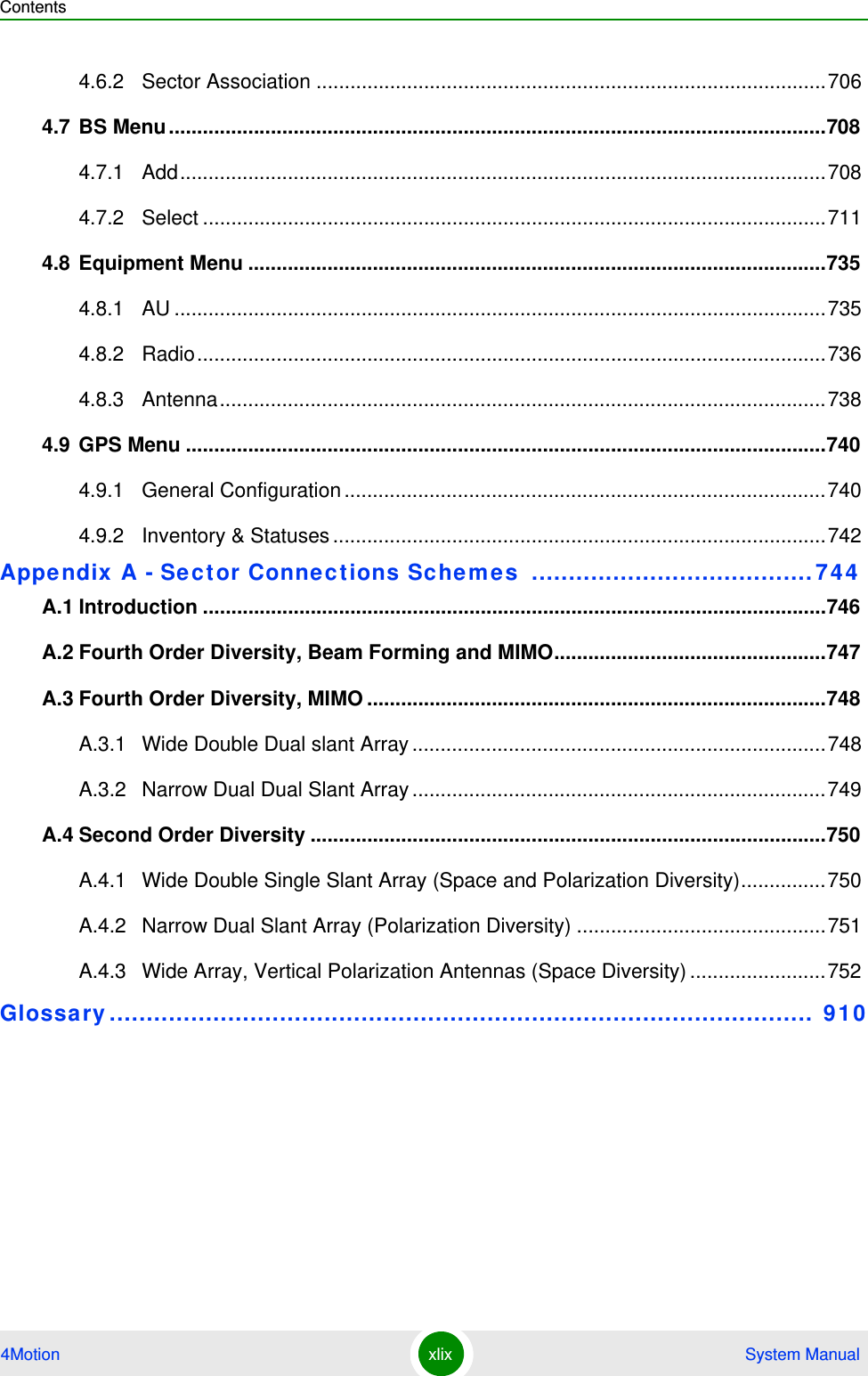
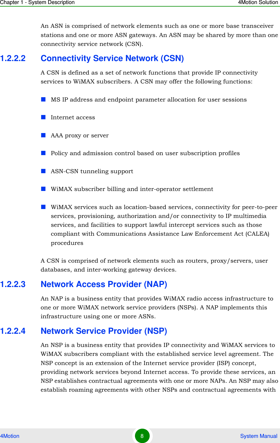
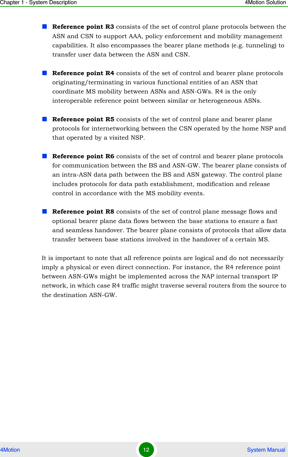
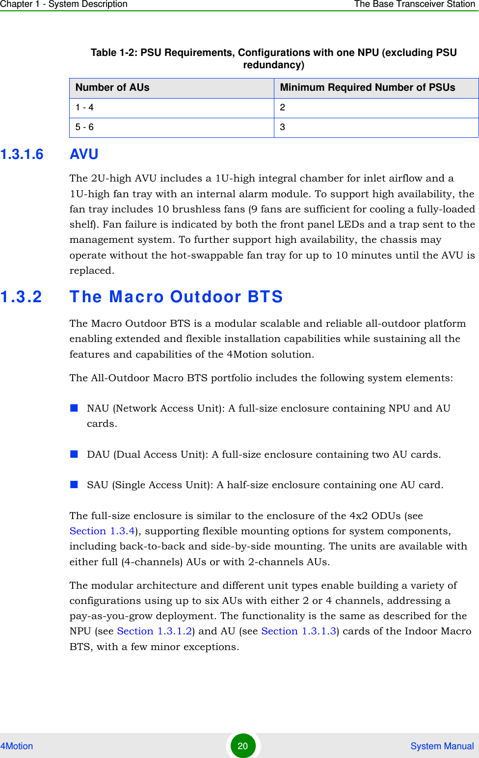
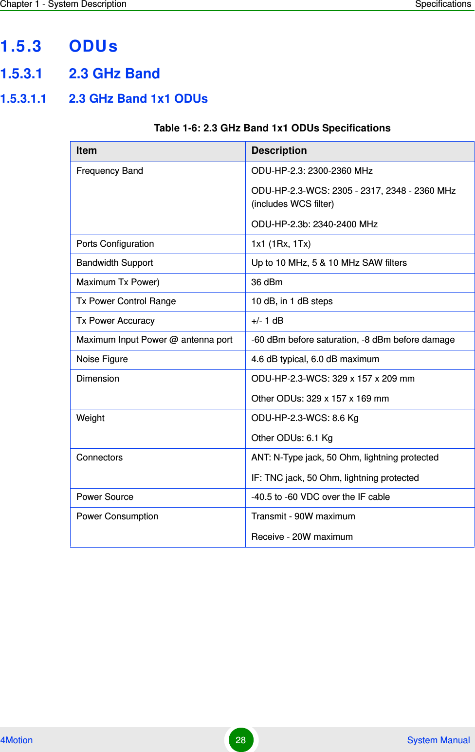
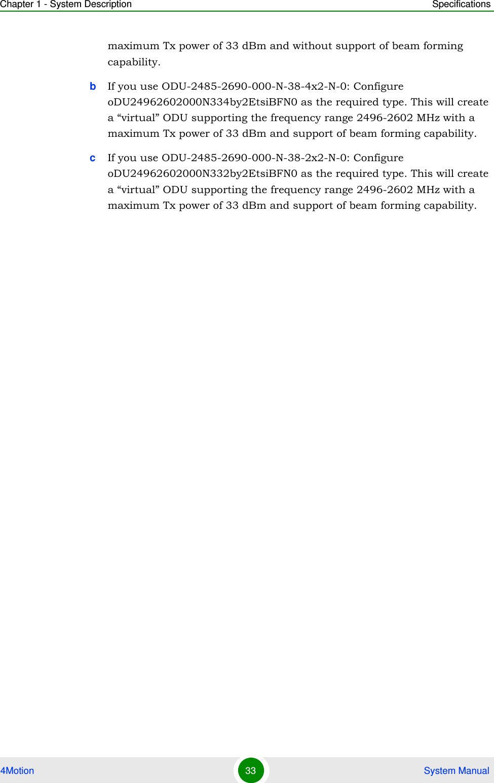
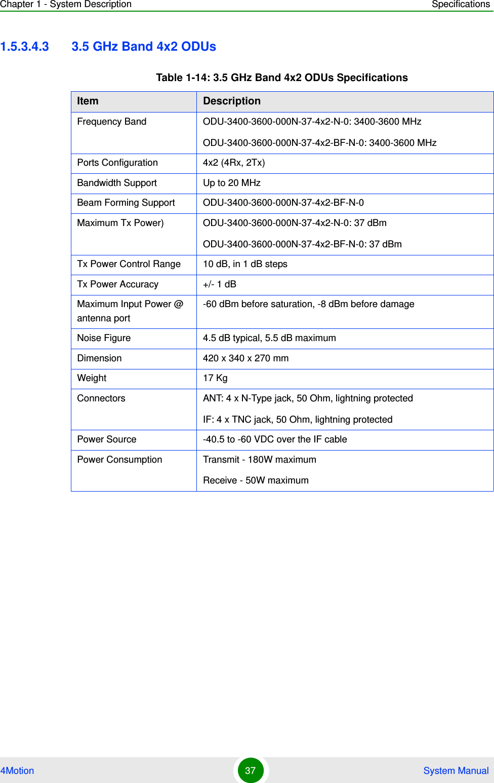
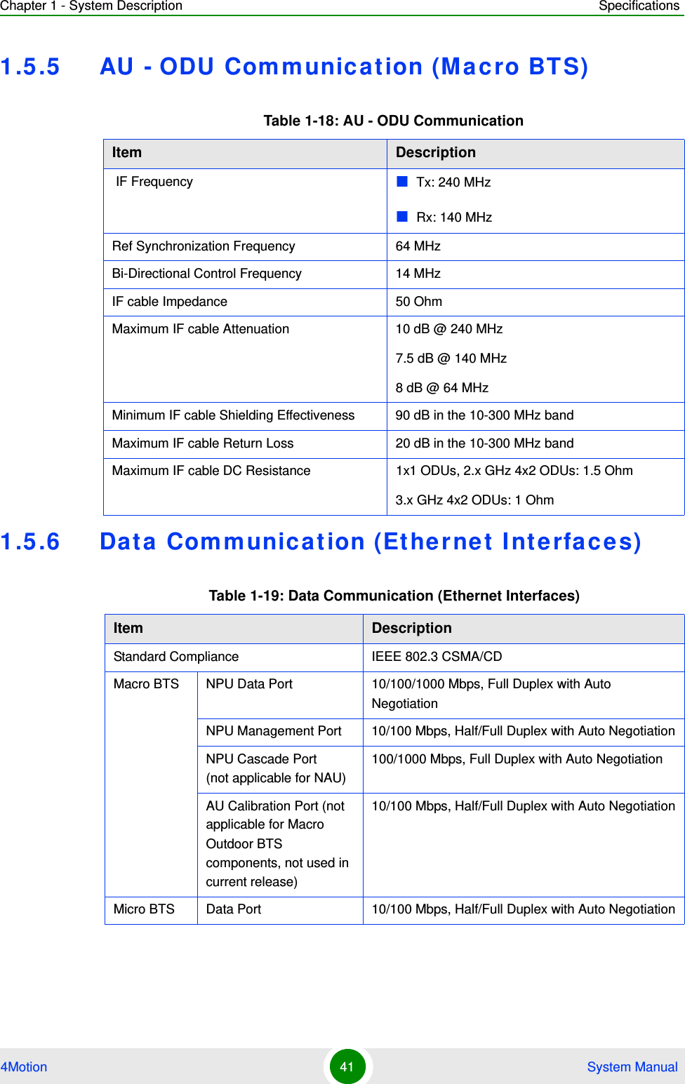
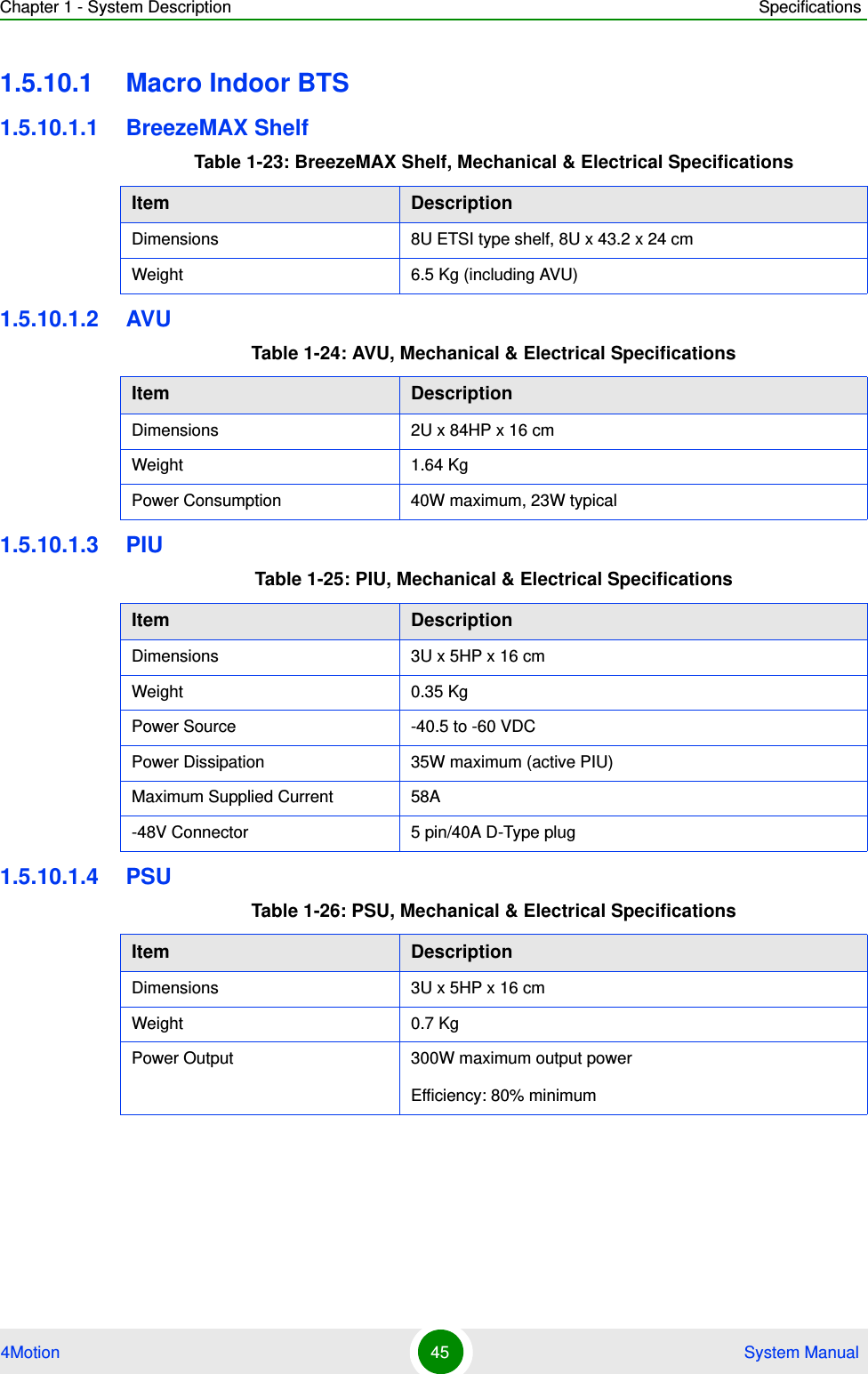
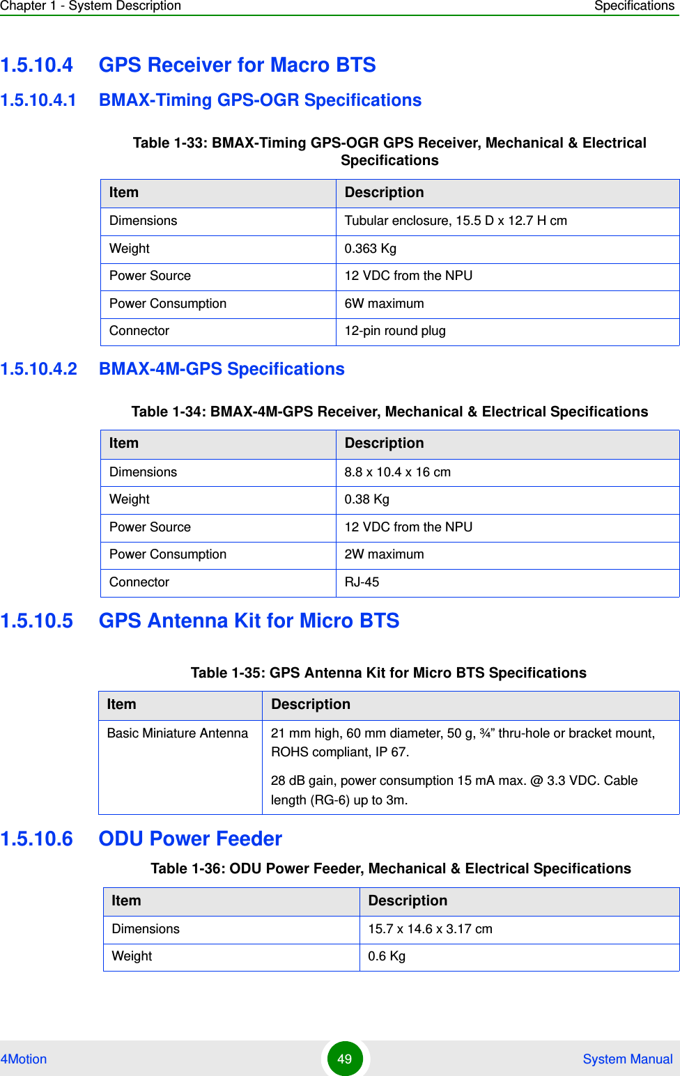
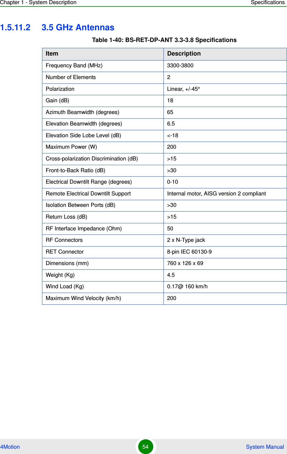
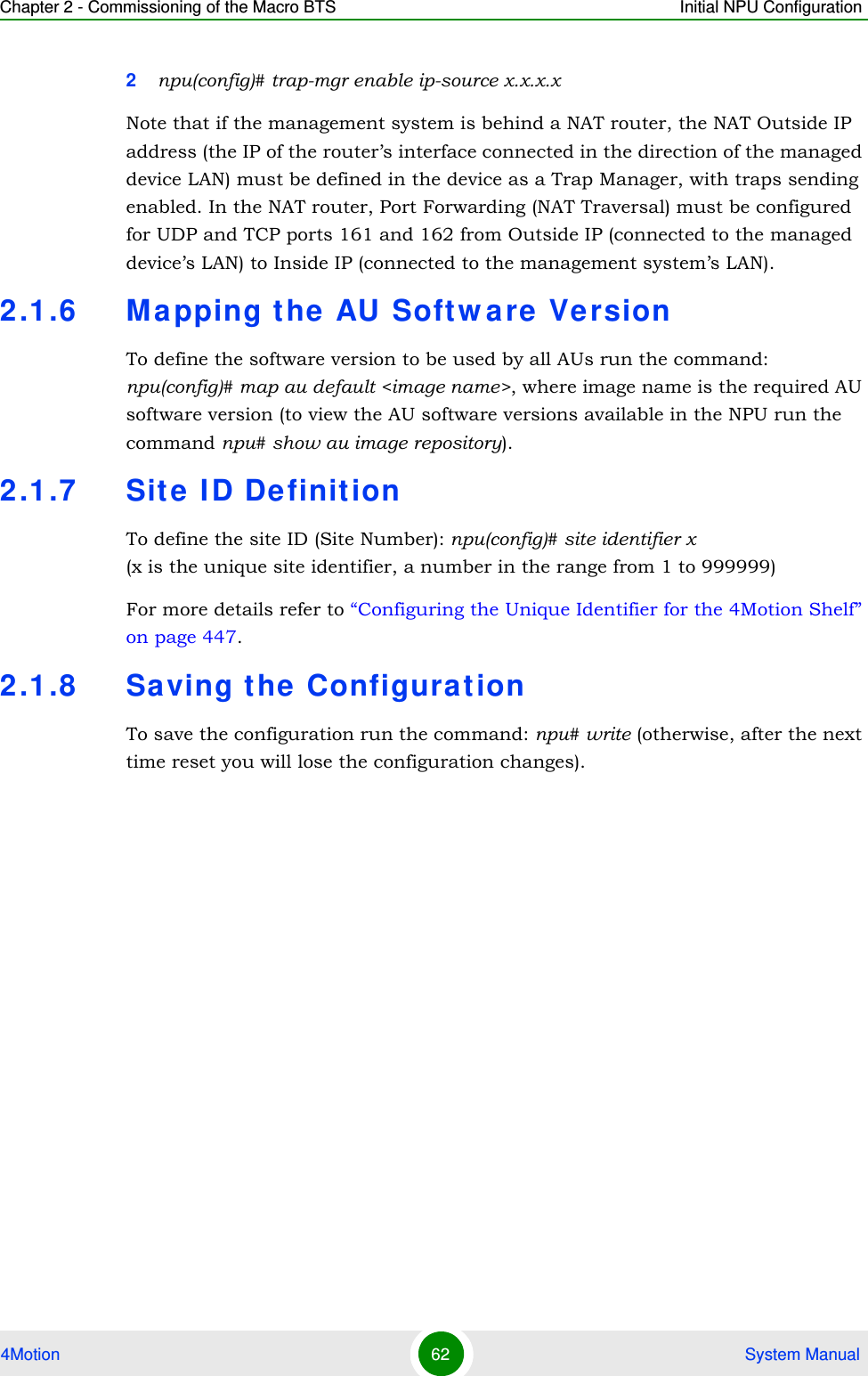
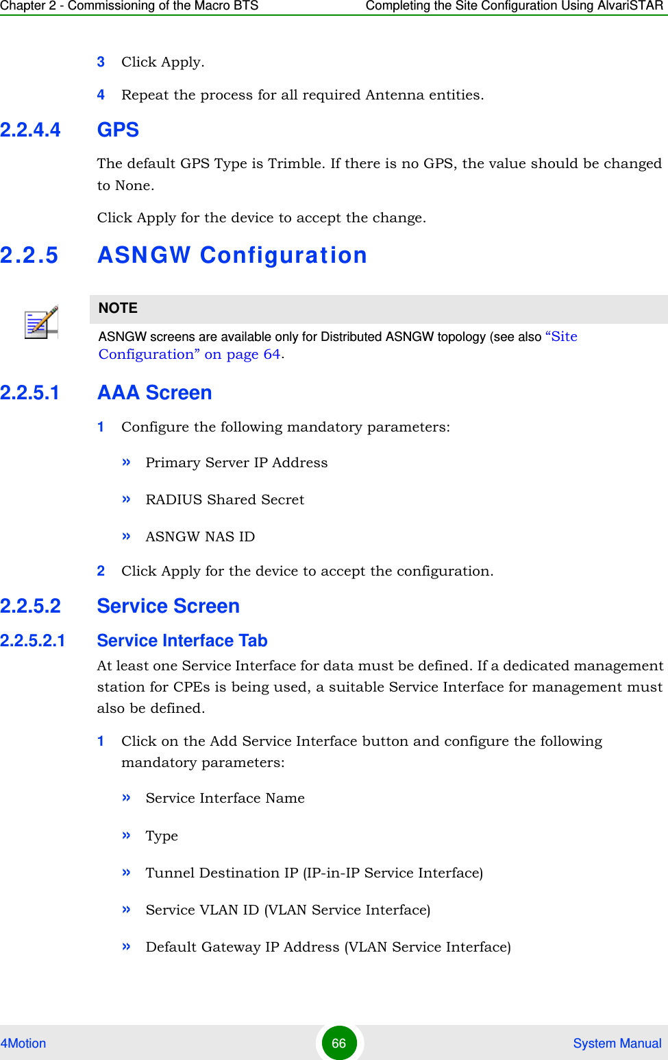
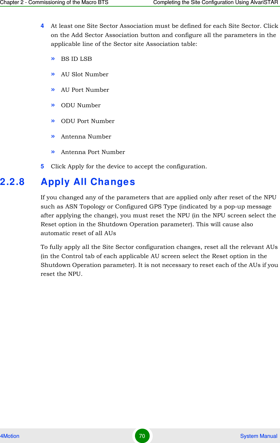
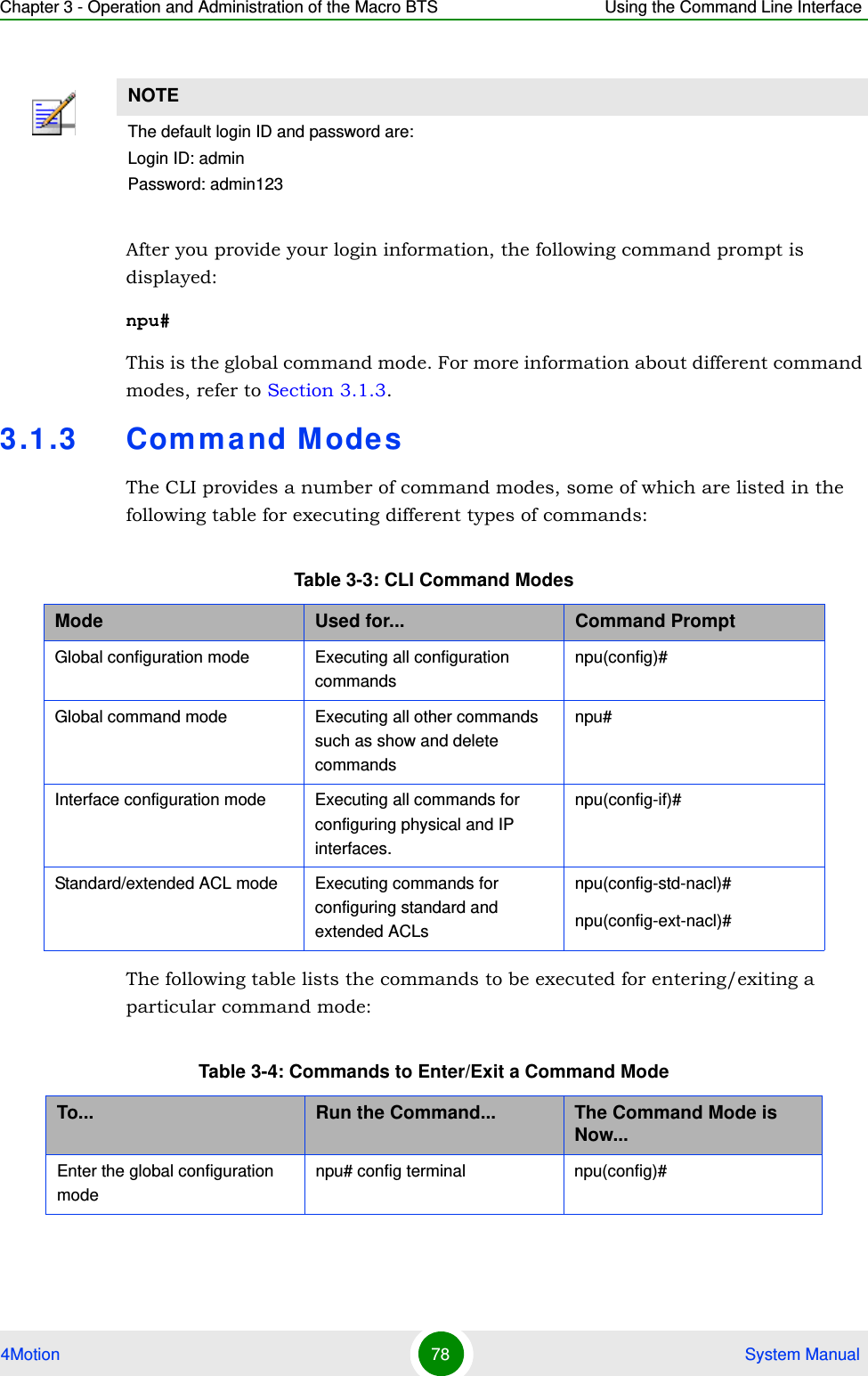
![Chapter 3 - Operation and Administration of the Macro BTS Using the Command Line Interface4Motion 86 System Manual3.1.6.2 Managing PrivilegesTo enable users to execute commands that require a higher privilege level (than their currently configured default level), you can configure a password for each privilege level. Other users can then use the password you have specified to enable a higher privilege level. This section describes the commands for:“Assigning a Password for a Privilege Level” on page 86“Deleting a Password for a Privilege Level” on page 873.1.6.2.1 Assigning a Password for a Privilege LevelTo assign a password for a privilege level, run the following command:npu(config)# enable password [Level <1-10>] <password> Syntax Description Parameter Description Presence Default ValuePossible Valuesusername <name>Indicates the username of the user to be deleted.Mandatory N/A String (upto 20 characters and case-sensitive)Command ModesGlobal configuration modeIMPORTANTOnly users who have logged in as admin can assign or delete passwords for any privilege level.IMPORTANTOnly users who have logged in as admin can execute this command.IMPORTANTAfter you execute this command, any user can use this password to enable the (higher) privilege level for which you have configured the password. For more information about using passwords for enabling higher privilege levels, refer Section 3.1.6.3.](https://usermanual.wiki/Alvarion-Technologies/MICRO-25.Manual-p1/User-Guide-1329242-Page-135.png)
![Chapter 3 - Operation and Administration of the Macro BTS Using the Command Line Interface4Motion 87 System Manual3.1.6.2.2 Deleting a Password for a Privilege LevelTo delete a password for a privilege level, run the following command:npu(config)# no enable password [Level <1-10>]IMPORTANTAn error may occur if:You are trying to configure a password for a privilege level that is higher than your default privilege level. The password that you have specified is more than 20 characters.The privilege level that you have specified is not within the range, 1-10.Command Syntaxnpu(config)# enable password [Level <1-10>] <password>Privilege Level10Syntax Description Parameter Description Presence Default ValuePossible Values[Level <1-10>] Indicates the privilege level for which a password is to be enabled.Optional 10 1-10<password> Denotes the password to be assigned for the current privilege level.Mandatory N/A String (up to 20 characters and case-sensitive)Command ModesGlobal configuration modeIMPORTANTOnly users who have logged in as admin can execute this command.](https://usermanual.wiki/Alvarion-Technologies/MICRO-25.Manual-p1/User-Guide-1329242-Page-136.png)
![Chapter 3 - Operation and Administration of the Macro BTS Using the Command Line Interface4Motion 88 System Manual3.1.6.3 Enabling/Disabling Higher Privilege LevelsYou can execute commands that require higher privilege levels. If the admin user has configured a password for that level, you can use that password to enable higher privilege levels.For example, if your privilege level is 1, you can provide the password configured for privilege level 10 to execute all commands that require privilege level 10.This section describes the commands for:“Enabling a Higher Privilege Level” on page 89“Returning to the Default Privilege Level” on page 90IMPORTANTAn error may occur if:The privilege level that you have specified is not within the range, 1-10.You are trying to delete a password for a privilege level that is higher than your default privilege level.Command Syntaxnpu(config)# no enable password [Level <1-10>]Privilege Level10Syntax Description Parameter Description Presence Default ValuePossible Values[Level <1-10>] Indicates the privilege level for which a password is to be disabled.Optional 10 1-10Command SyntaxGlobal configuration mode](https://usermanual.wiki/Alvarion-Technologies/MICRO-25.Manual-p1/User-Guide-1329242-Page-137.png)
![Chapter 3 - Operation and Administration of the Macro BTS Using the Command Line Interface4Motion 89 System Manual3.1.6.3.1 Enabling a Higher Privilege Level1Log in to the CLI.2Run the following command to specify the privilege level and password:npu(config)# enable [Level <1-10>]3At the password prompt, specify the password configured for the privilege level that you have specified.If you specify the correct password, you are logged in to the CLI with the privilege level that you had specified. You can now execute all commands that require the current privilege level.You can, at any time, return to your default privilege level. For details, refer Section 3.1.6.3.2.To enable a higher privilege level:NOTEYou can display your current privilege level, using the following command:npu# show privilege NOTEAn error may occur if:You have specified an incorrect password. Remember that all passwords are case-sensitive.No password is not configured for the privilege level you are trying to access.Command Syntaxnpu(config)# enable [Level <1-10>]Privilege Level10](https://usermanual.wiki/Alvarion-Technologies/MICRO-25.Manual-p1/User-Guide-1329242-Page-138.png)
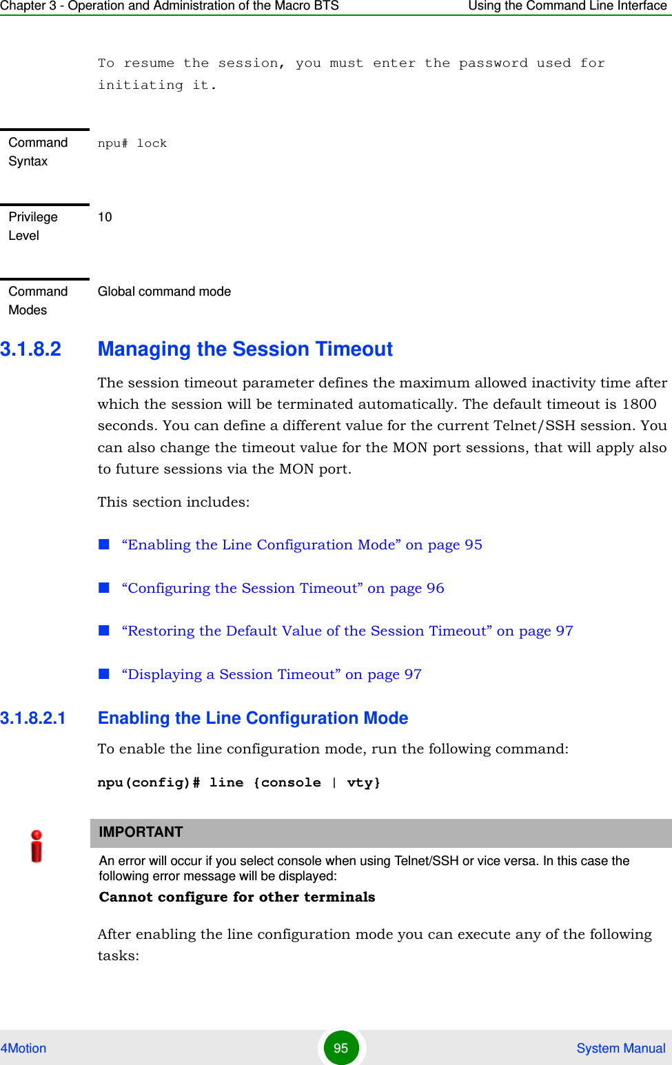
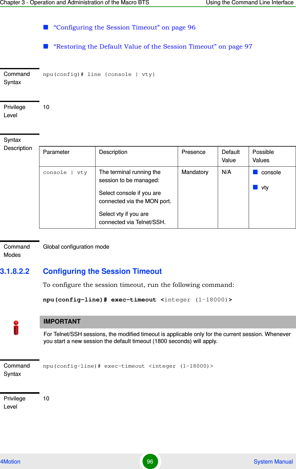
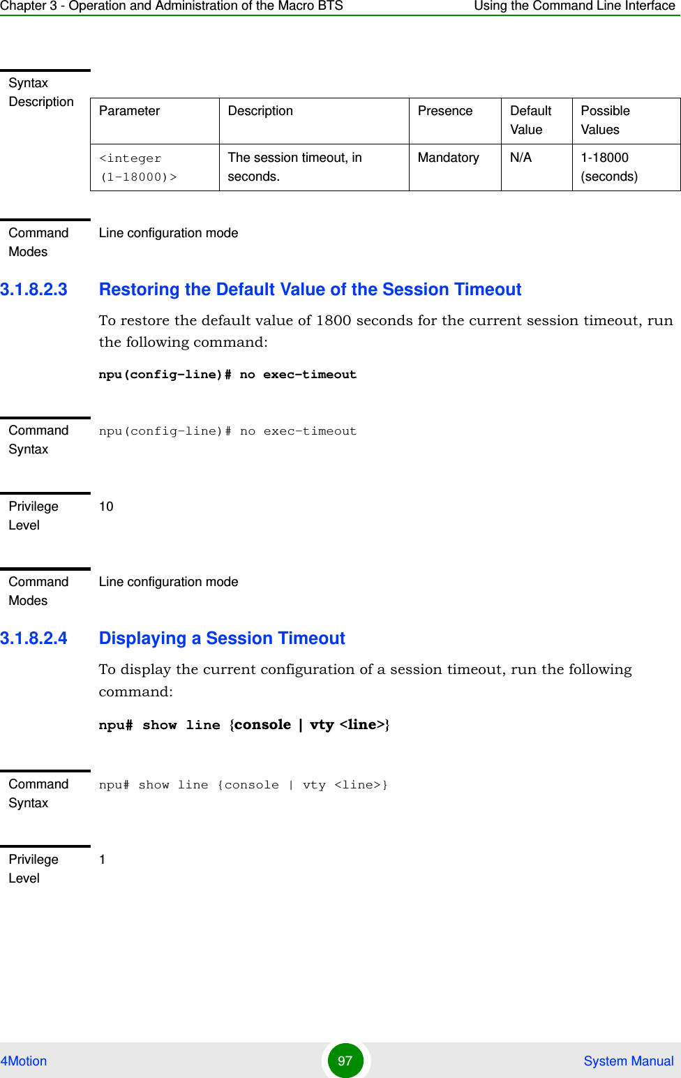
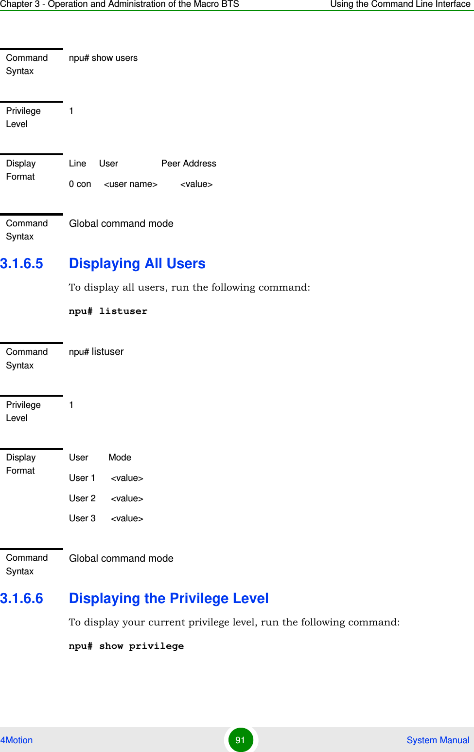
![Chapter 3 - Operation and Administration of the Macro BTS Using the Command Line Interface4Motion 90 System Manual3.1.6.3.2 Returning to the Default Privilege LevelRun the following command to disable the current privilege level, and return to your default privilege level:npu(config)# disable [Level <1-10>]After you run this command, you automatically return to your default privilege level. You can display your current privilege level, using the following command:npu# show privilege 3.1.6.4 Displaying Active UsersTo display all active users, run the following command:npu# show usersSyntax Description Parameter Description Presence Default ValuePossible Values[Level <1-10>] Indicates the privilege level you want to enable.Mandatory N/A 1-10Command ModesGlobal configuration modeCommand Syntaxnpu(config)# disable [Level <1-10>]Privilege Level1Syntax Description Parameter Description Presence Default ValuePossible Values[Level <1-10>] Indicates the privilege level you want to disable.Mandatory N/A 1-10Command ModesGlobal command mode](https://usermanual.wiki/Alvarion-Technologies/MICRO-25.Manual-p1/User-Guide-1329242-Page-139.png)
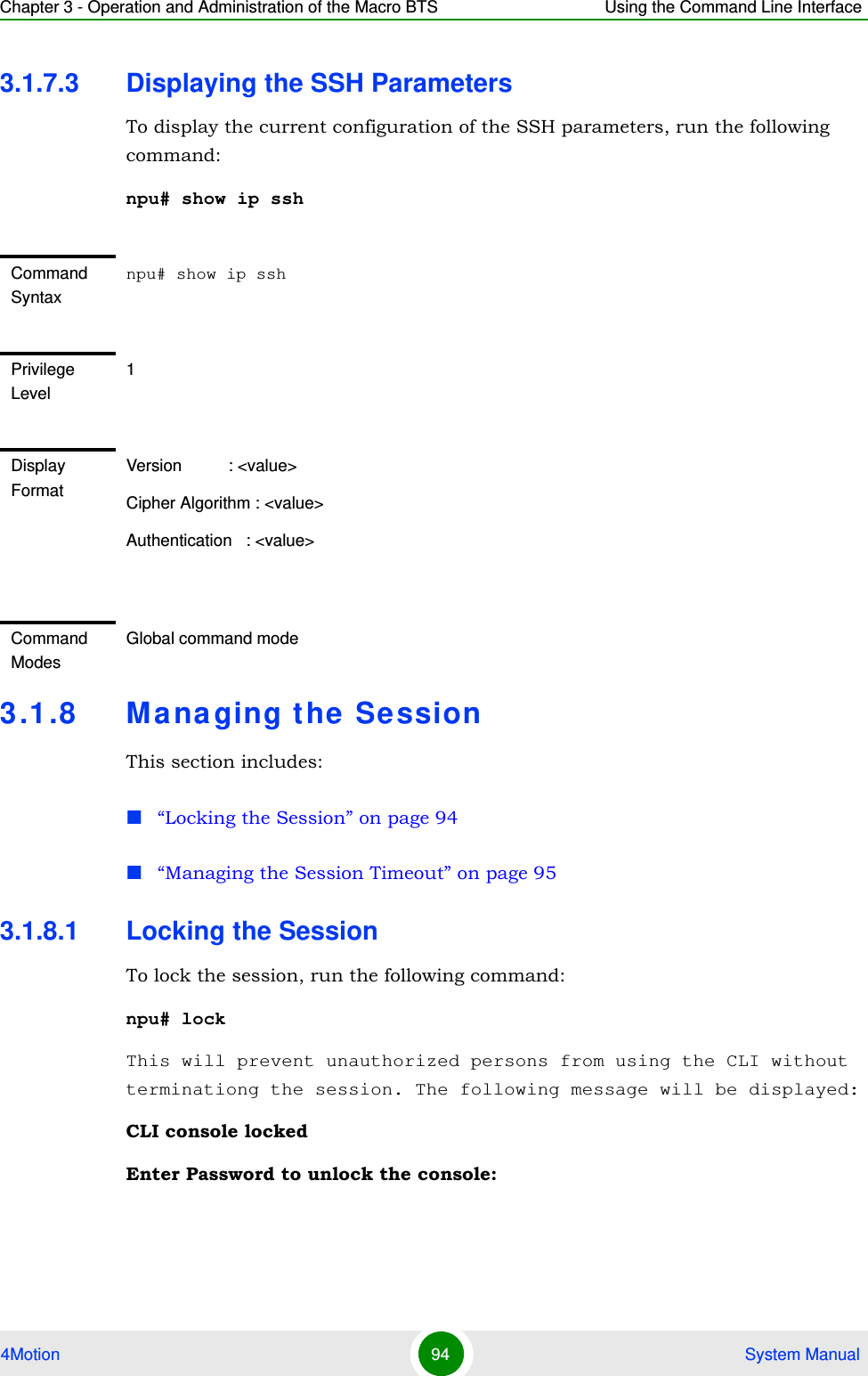
![Chapter 3 - Operation and Administration of the Macro BTS Using the Command Line Interface4Motion 92 System Manual3.1.7 Ma na ging Se cure Shell (SSH) Pa ram et ersThe SSH parameters define the parameters used for establishing remote secure access to the device using SSH protocol rather than the plaintext-based insecure Telnet protocol.This section includes:“Configuring SSH Parameters” on page 92“Restoring the Default Values of SSH Parameters” on page 93“Displaying the SSH Parameters” on page 943.1.7.1 Configuring SSH ParametersTo configure SSH parameters, run the following command:npu(config)# ip ssh {version compatibility | cipher ([des-cbc] [3des-cbc]) | auth ([hmac-md5] [hmac-sha1]) }Command Syntaxnpu# show privilegePrivilege Level1Display FormatCurrent privilege level is <value>Command SyntaxGlobal command modeCommand Syntaxnpu(config)# ip ssh {version compatibility | cipher ([des-cbc] [3des-cbc]) | auth ([hmac-md5] [hmac-sha1]) }Privilege Level10](https://usermanual.wiki/Alvarion-Technologies/MICRO-25.Manual-p1/User-Guide-1329242-Page-141.png)
![Chapter 3 - Operation and Administration of the Macro BTS Using the Command Line Interface4Motion 93 System Manual3.1.7.2 Restoring the Default Values of SSH ParametersTo restore the default value of one or more SSH parameters, run the following command:npu(config)# no ip ssh {version compatibility | cipher ([des-cbc] [3des-cbc]) | auth ([hmac-md5] [hmac-sha1]) }.To restore the default values of all SSH parameters run the following command:npu(config)# no ip sshSyntax Description Parameter Description Presence Default ValuePossible Valuesversion compatibilityThe SSH version that can be used: The default is SSH version 2. The command npu(config)# ip ssh version compatibility enables compatibility with both SSH version 1 and SSH version 2.Optional SSH2 version compatibilitycipher ([des-cbc] [3des-cbc])The encryption algorithm used by the SSH protocol: DES-CCBC or 3DES-CBC.Optional des-cbc des-cbc3des-cbcauth ([hmac-md5] [hmac-sha1])The authentication mechanism used by the SSH protocol: HMAC-MD5 or HMAC-SHA1.OPtional hmac-sha1hmac-md5hmac-sha1Command ModesGlobal configuration modeCommand Syntaxnpu(config)# no ip ssh {version compatibility | cipher ([des-cbc] [3des-cbc]) | auth ([hmac-md5] [hmac-sha1]) }Privilege Level10Command ModesGlobal configuration mode](https://usermanual.wiki/Alvarion-Technologies/MICRO-25.Manual-p1/User-Guide-1329242-Page-142.png)