Alvarion Technologies MICRO-25 Microbase station transceiver User Manual 4Motion System Manual
Alvarion Technologies Ltd. Microbase station transceiver 4Motion System Manual
Contents
- 1. Manual p1
- 2. Manual p2
- 3. Manual p3
- 4. Manual p4
- 5. Manual p5
Manual p2
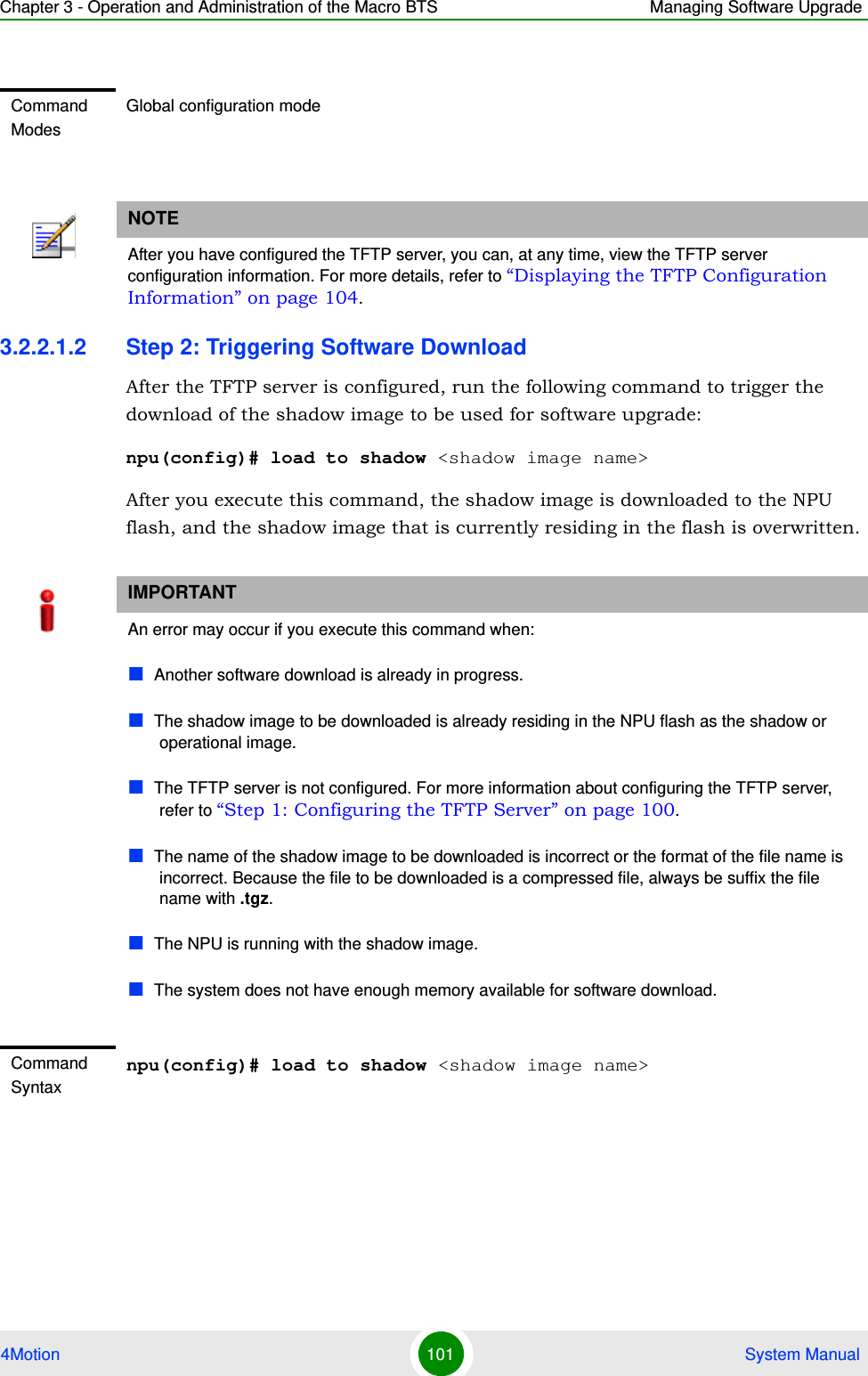
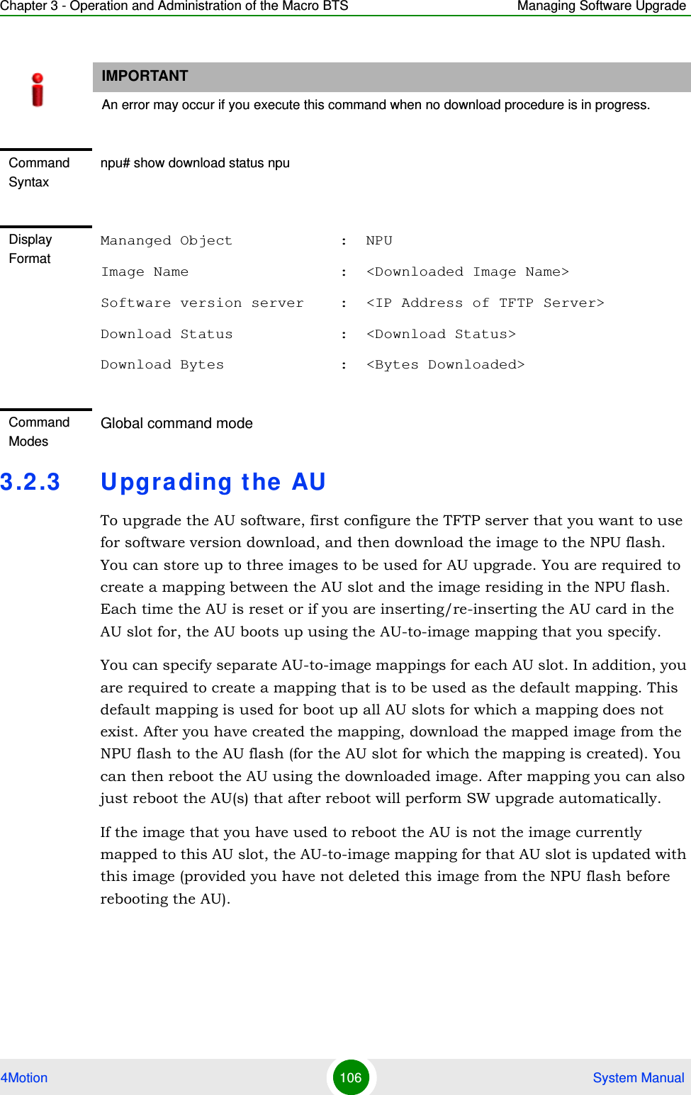
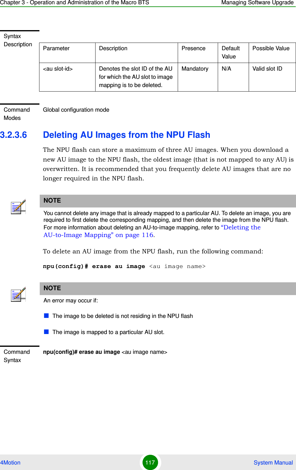
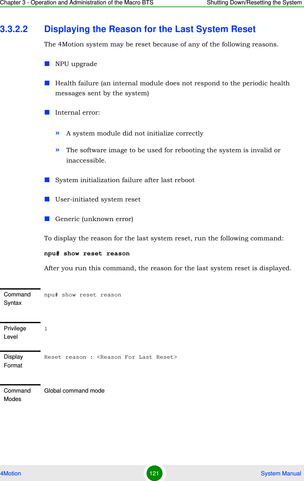
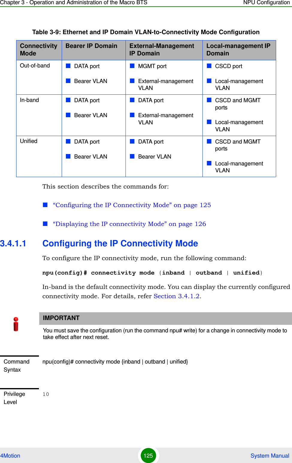
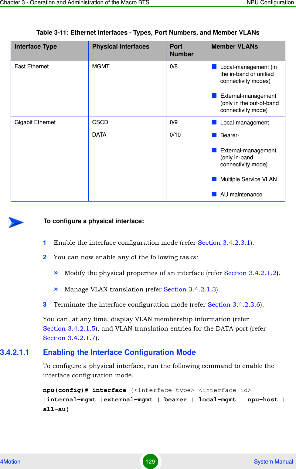
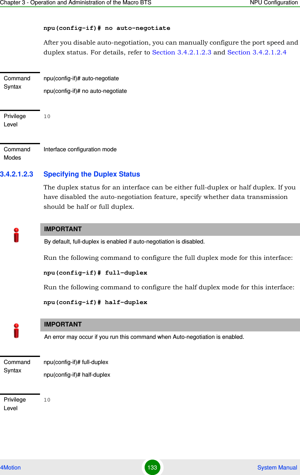
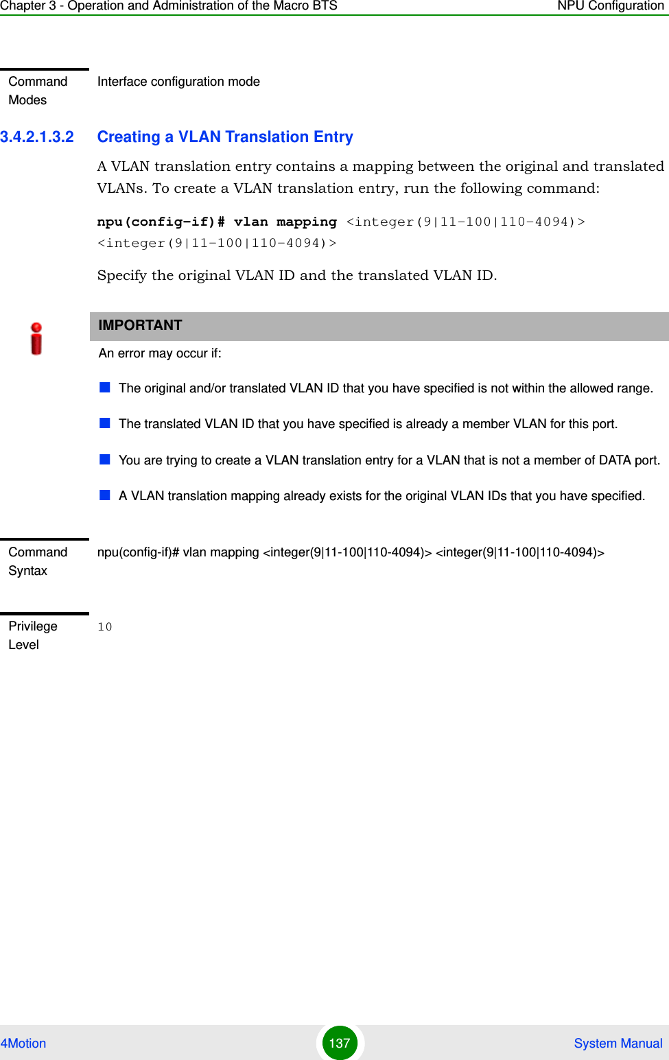
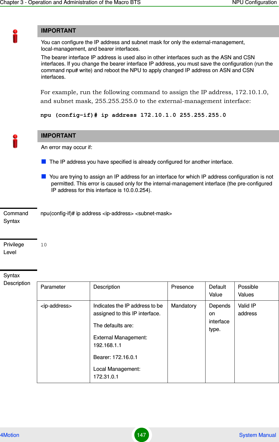
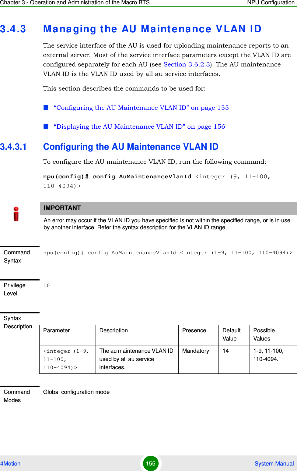
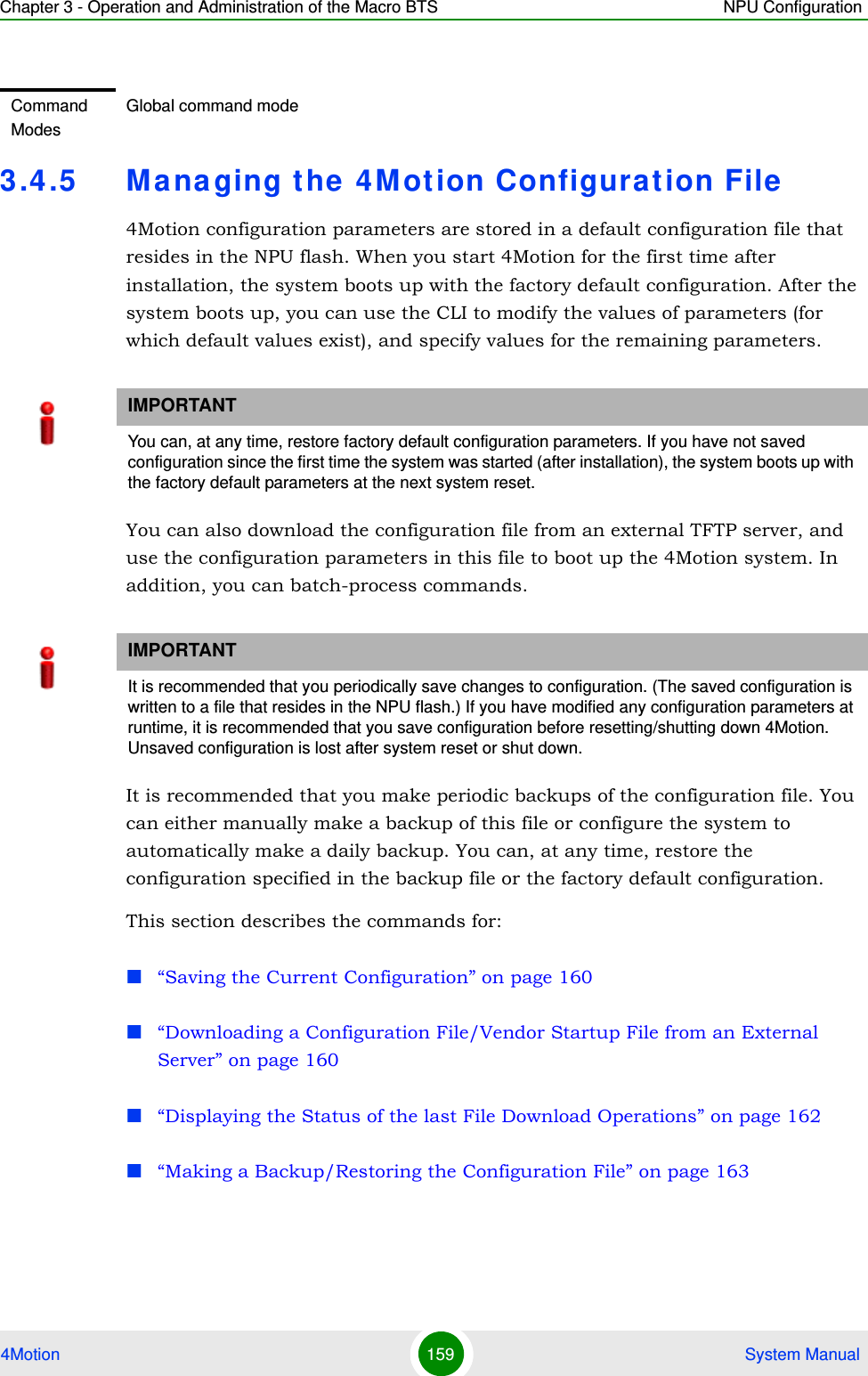
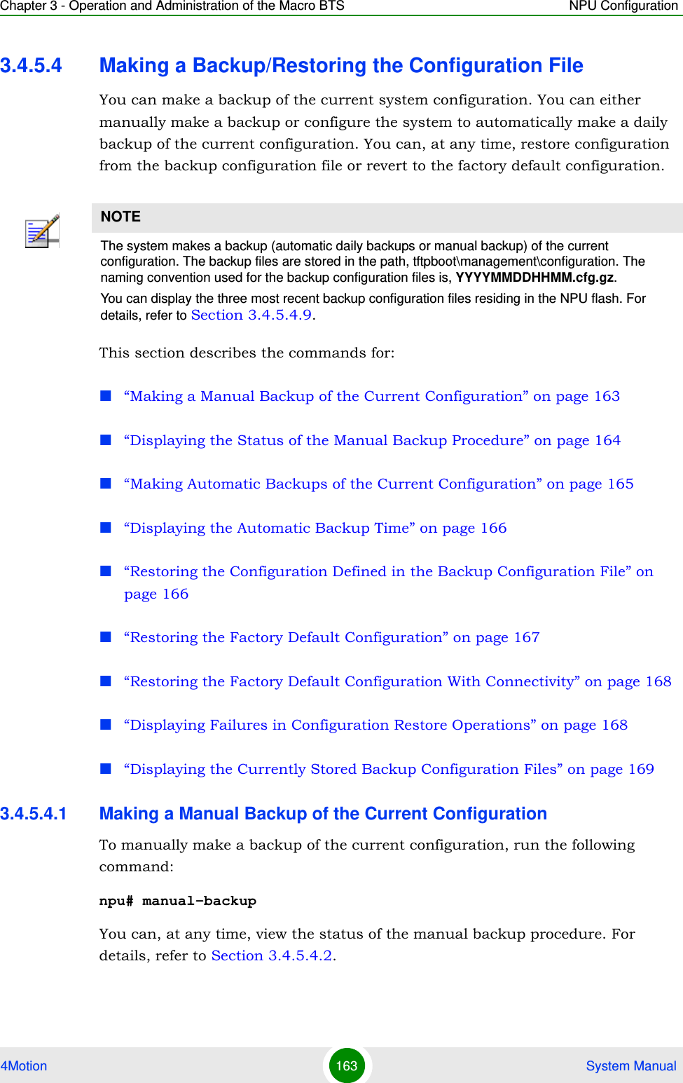
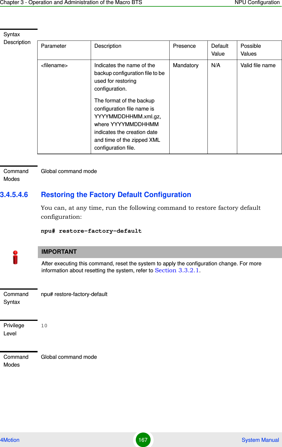
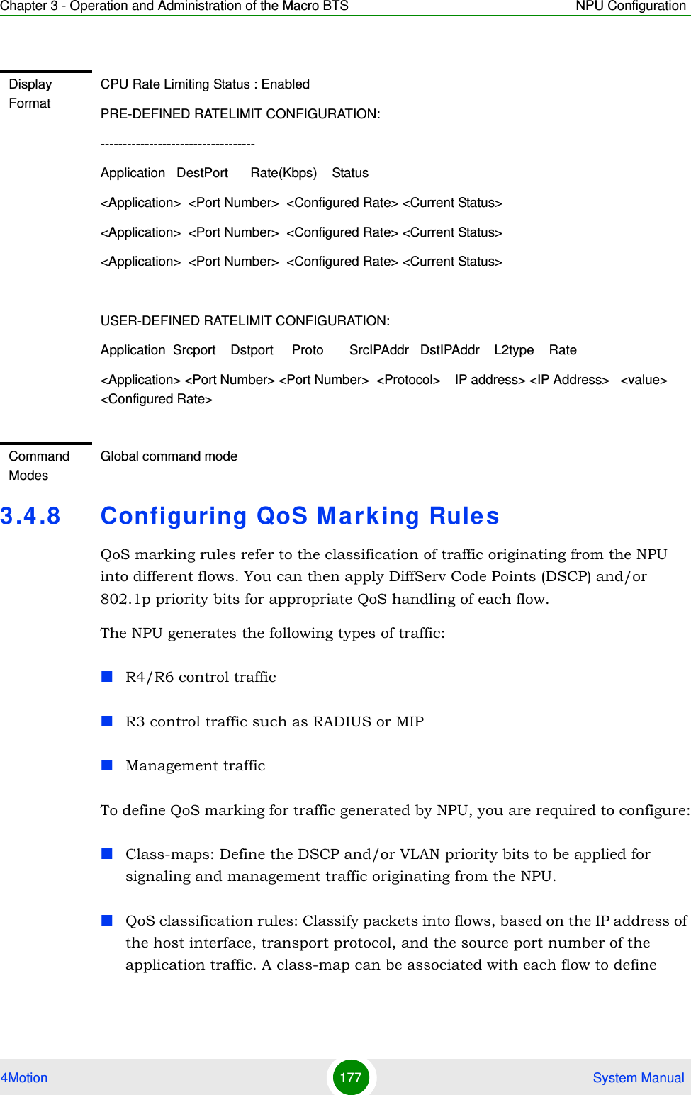
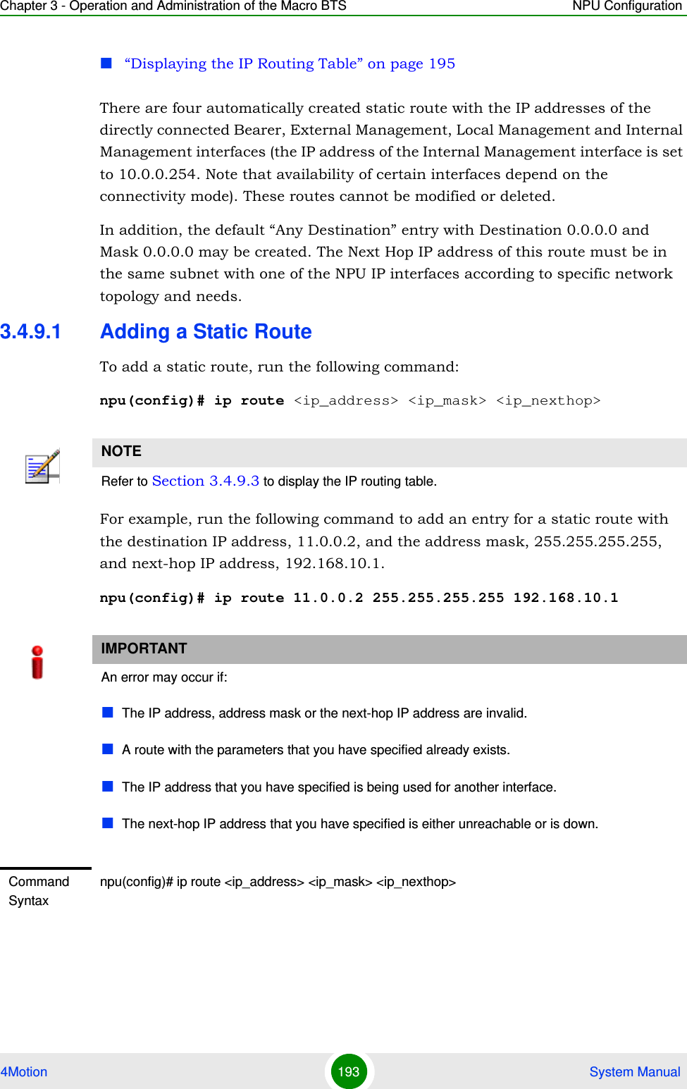
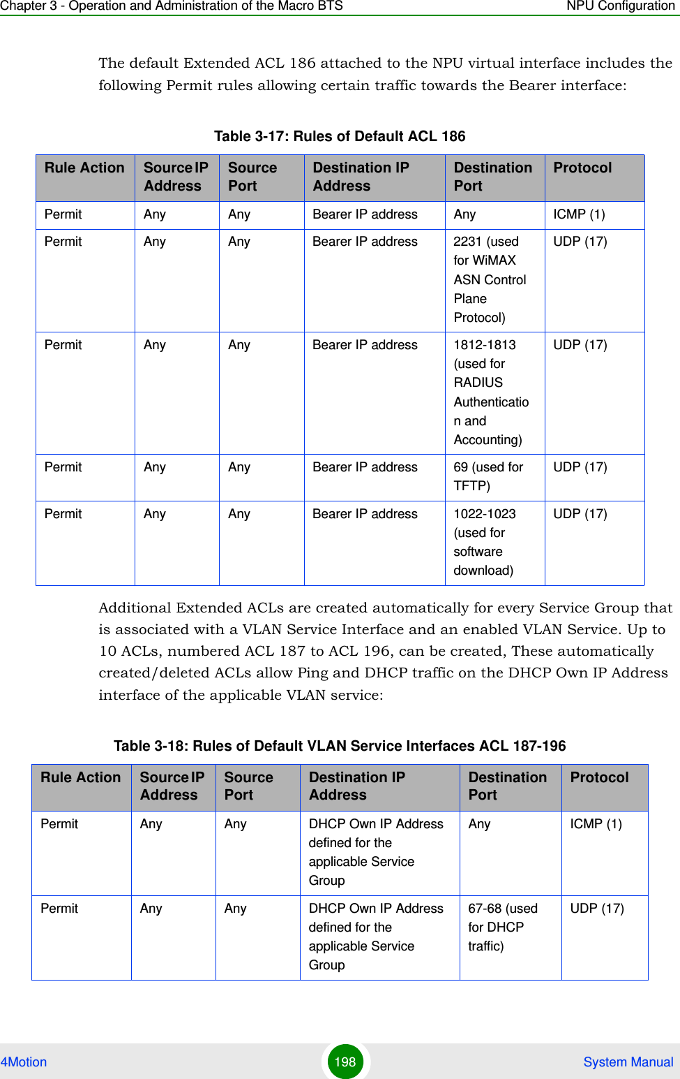
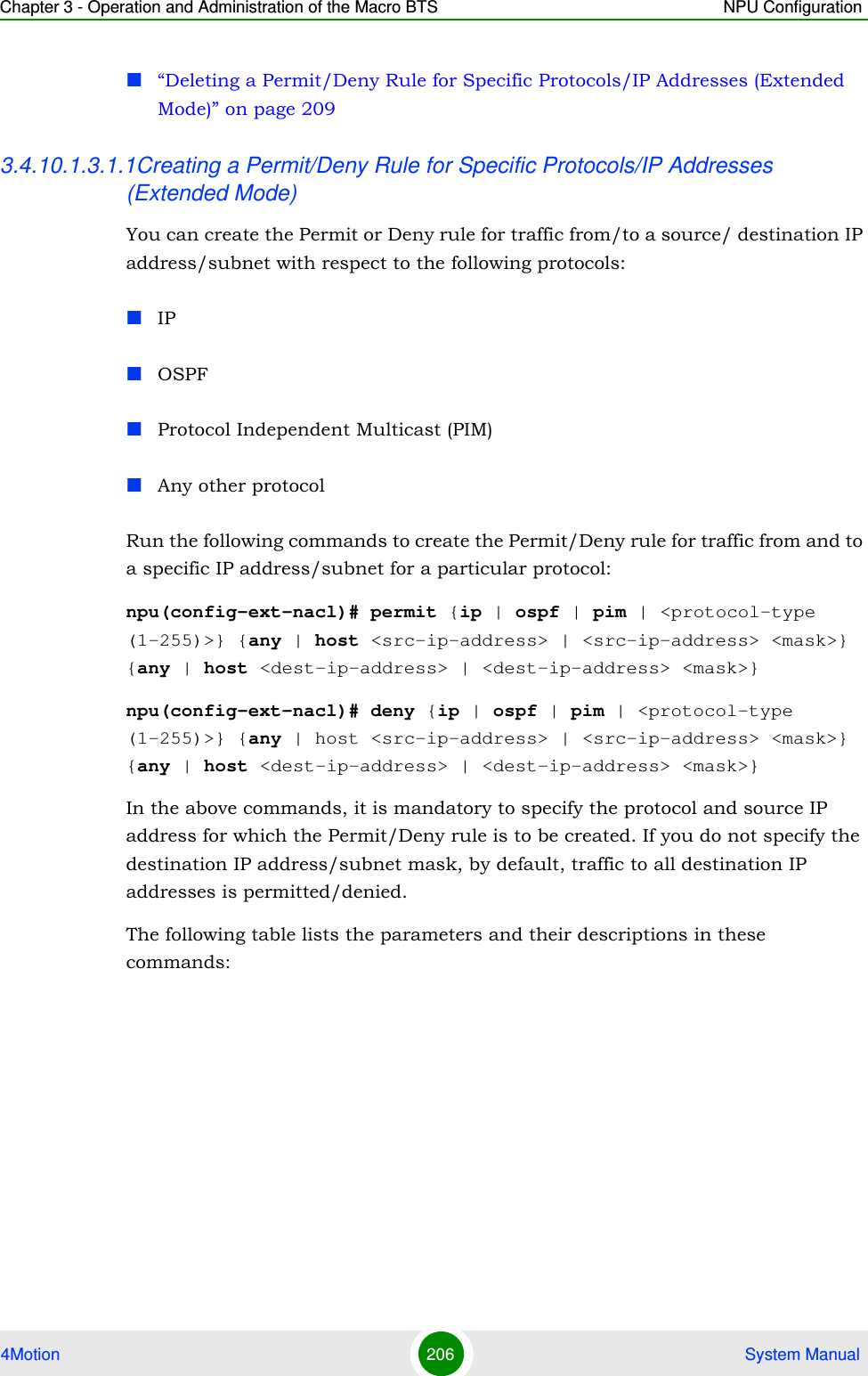
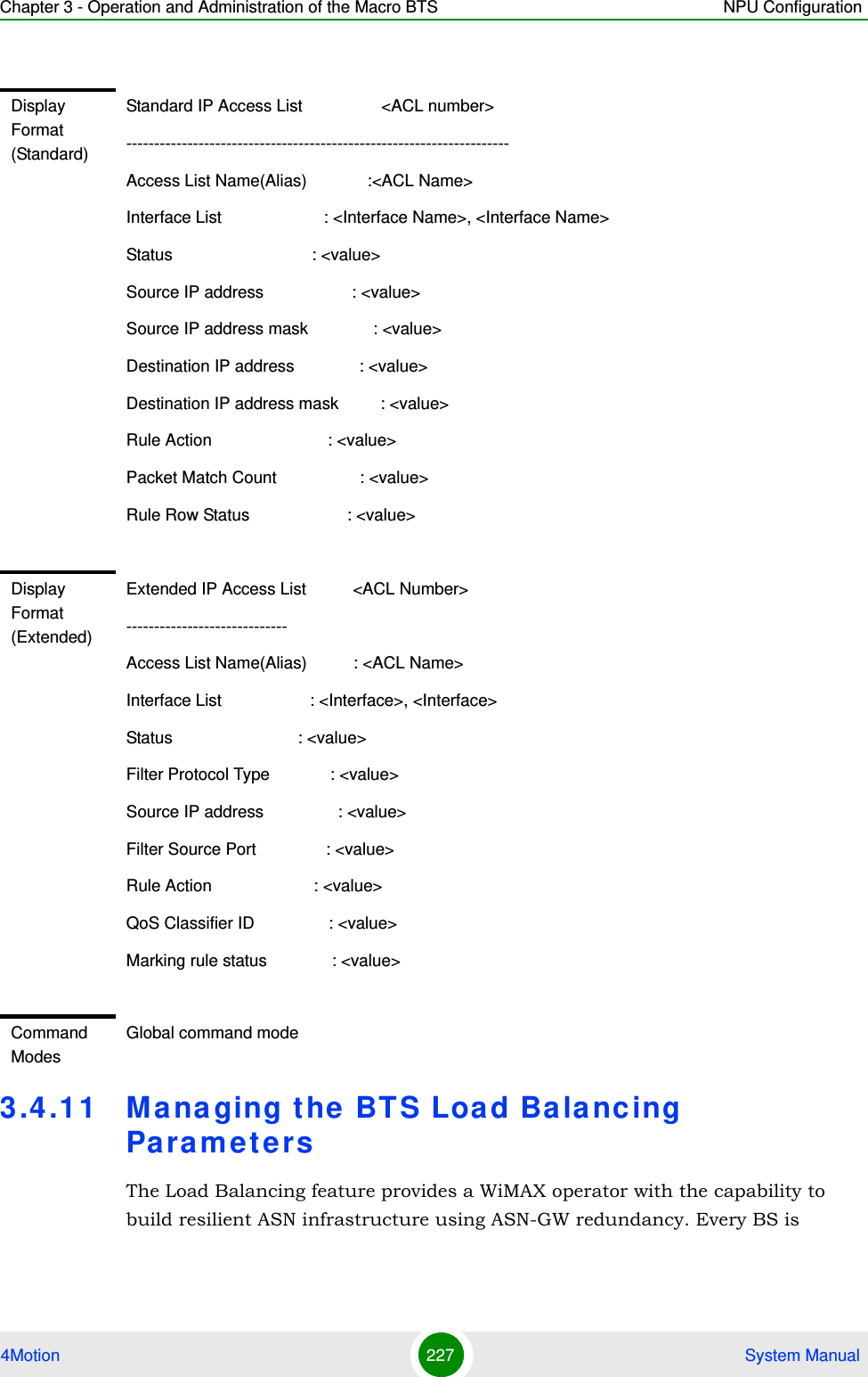
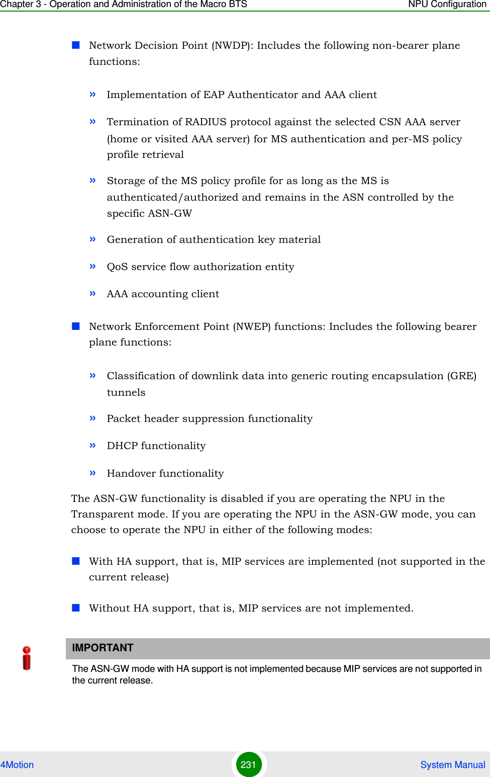
![Chapter 3 - Operation and Administration of the Macro BTS Managing Software Upgrade4Motion 102 System Manual3.2.2.1.3 Step 3: Resetting and Booting the NPU Using the Shadow ImageAfter the shadow image is downloaded to the NPU flash, run the following command to reboot the NPU with the downloaded shadow image:npu(config)# reboot from shadow [<shadow image name>]In the above command, you can specify the shadow image name that is to be used for NPU reboot. If you do not specify a value for the shadow image name parameter, the shadow image that was last downloaded is used for rebooting the NPU.Syntax Description Parameter Description Presence Default ValuePossible Values<shadow image name>Denotes the name of the shadow image that is to be downloaded to the NPU flash. The name of this file should always be suffixed with .tgz.Mandatory N/A <Valid shadow image name>.tgzCommand ModesGlobal configuration modeNOTEAfter you have triggered the download procedure, you can at any time, obtain information about the download status. For more details, refer to “Displaying the Download Status Information” on page 105. Command Syntaxnpu(config)# reboot from shadow [<shadow image name>]Syntax Description Parameter Description Presence Default ValuePossible Value<shadow image name>Denotes the name of the shadow image that is to be used for rebooting the NPU.If you do not specify a value for this parameter, the last downloaded shadow image is used for rebooting the NPU.Optional N/A Valid shadow image name](https://usermanual.wiki/Alvarion-Technologies/MICRO-25.Manual-p2/User-Guide-1329243-Page-2.png)
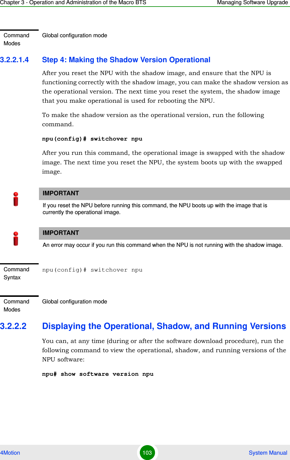
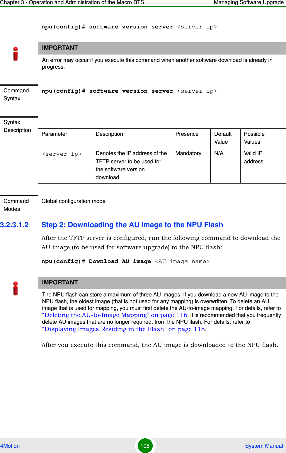
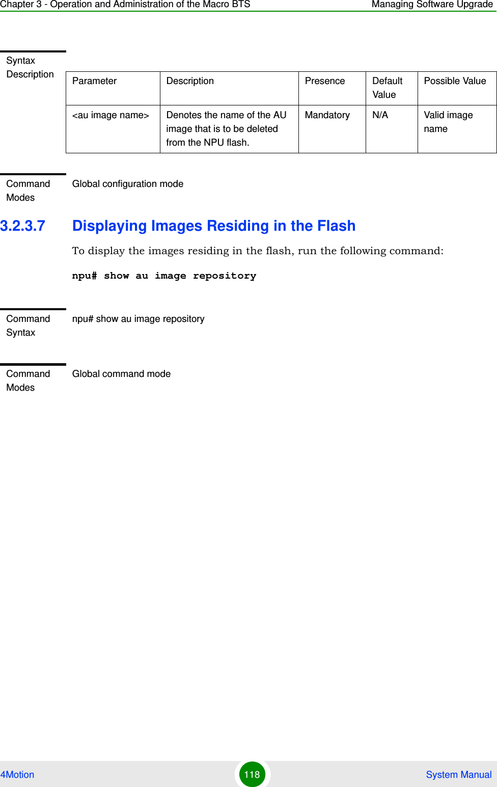
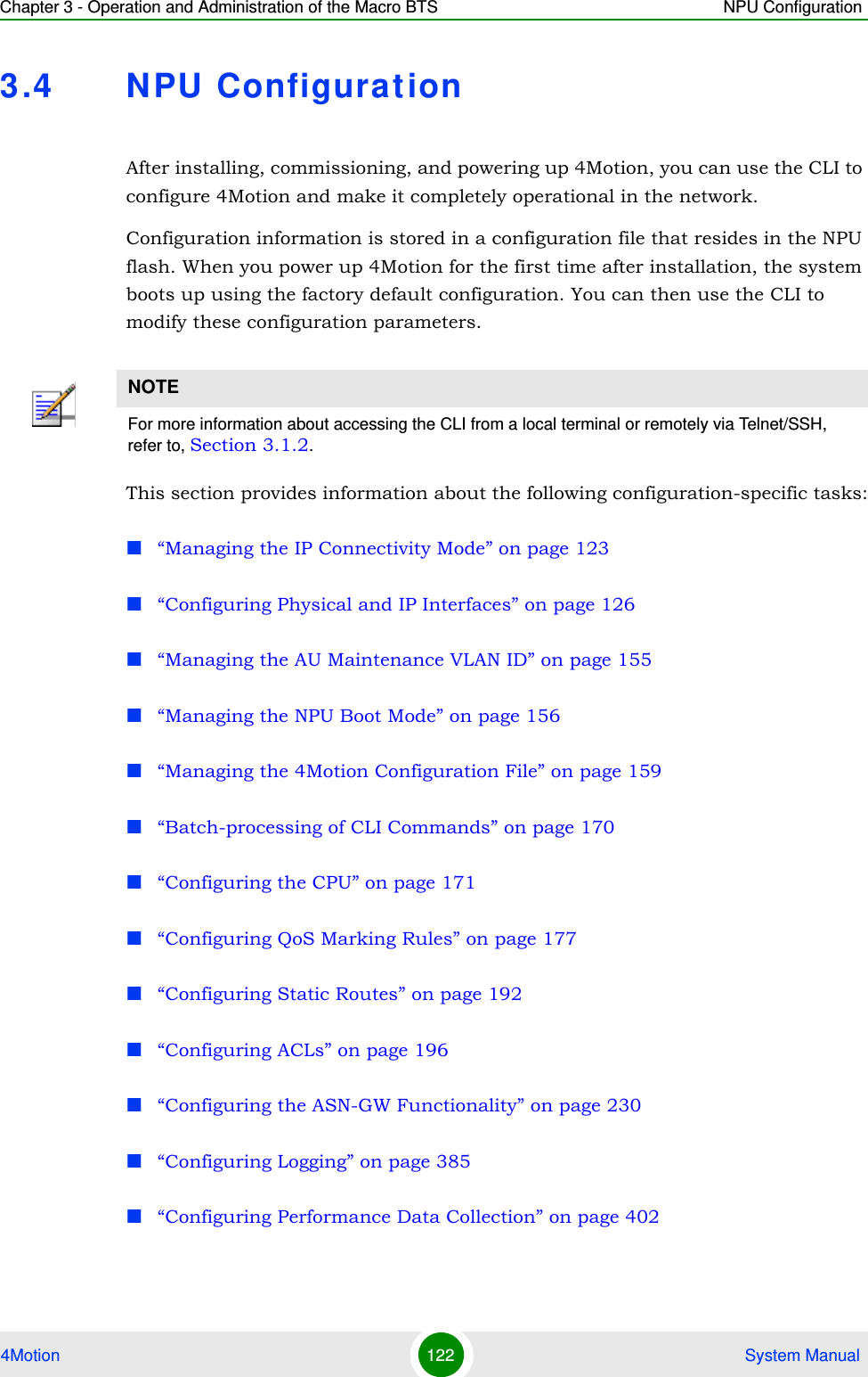
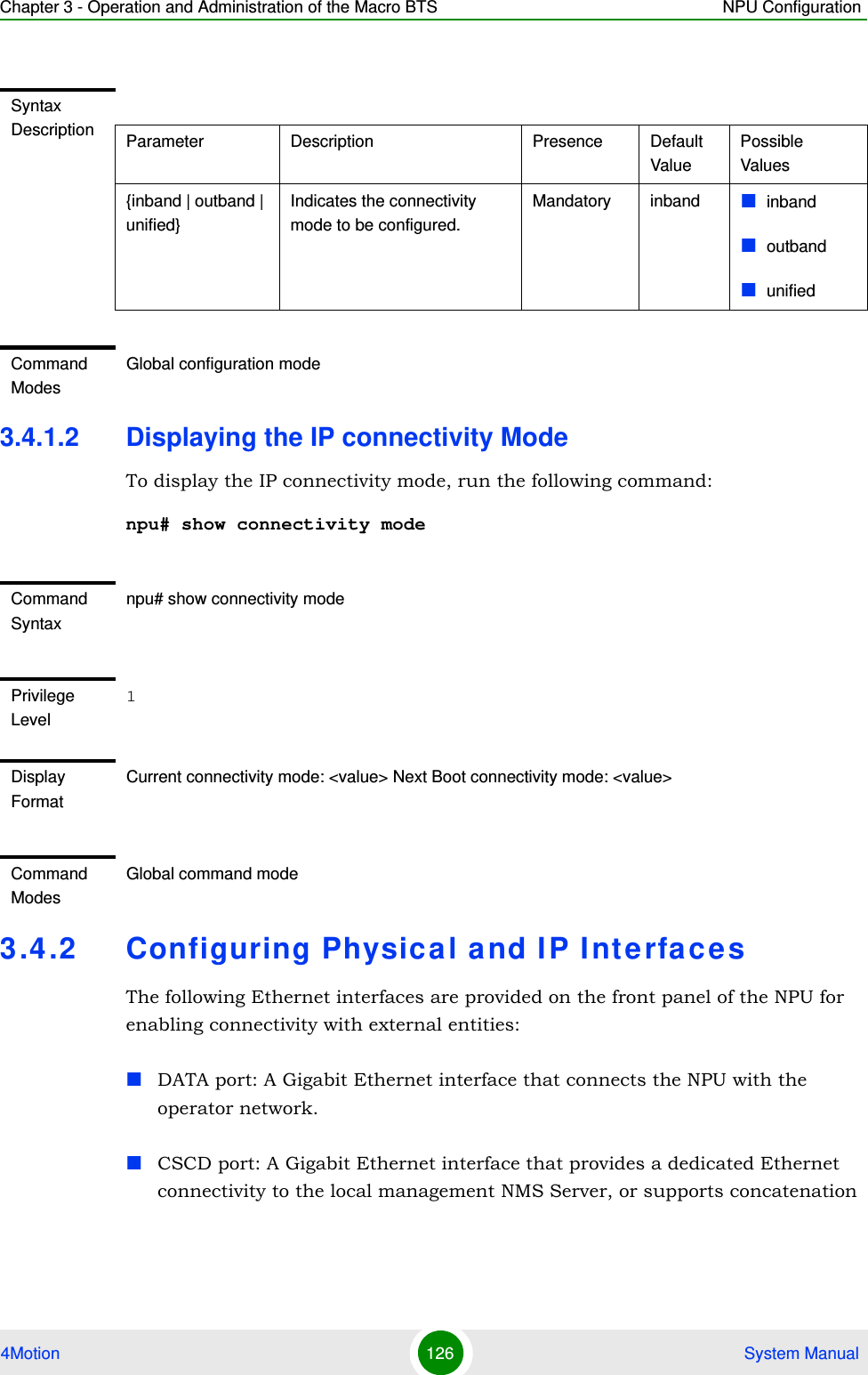
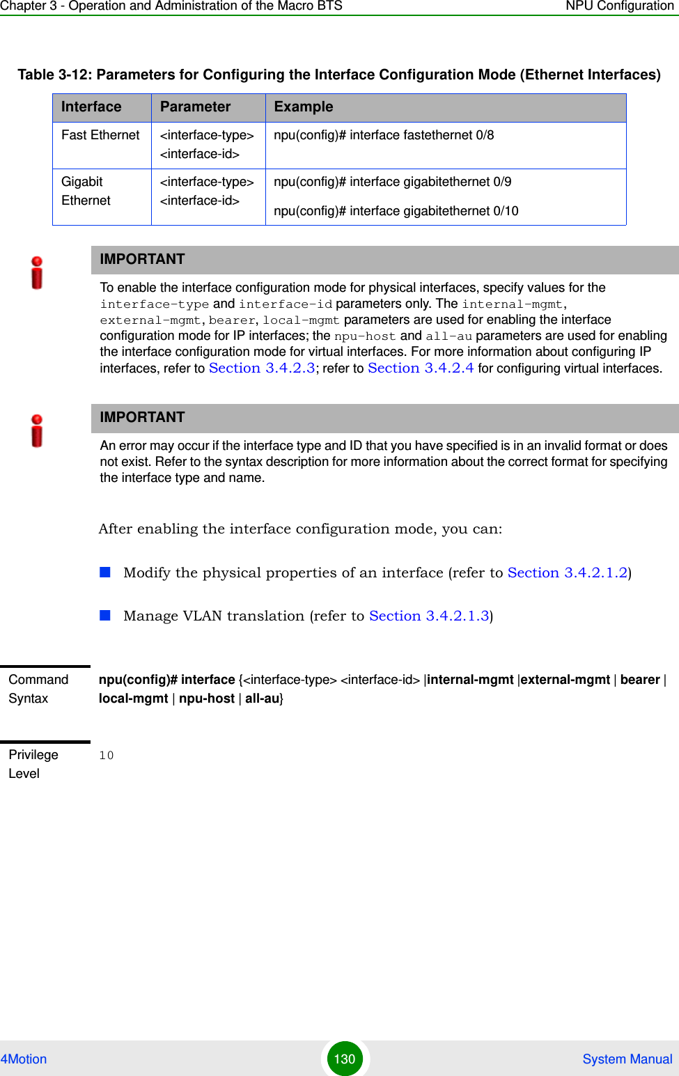
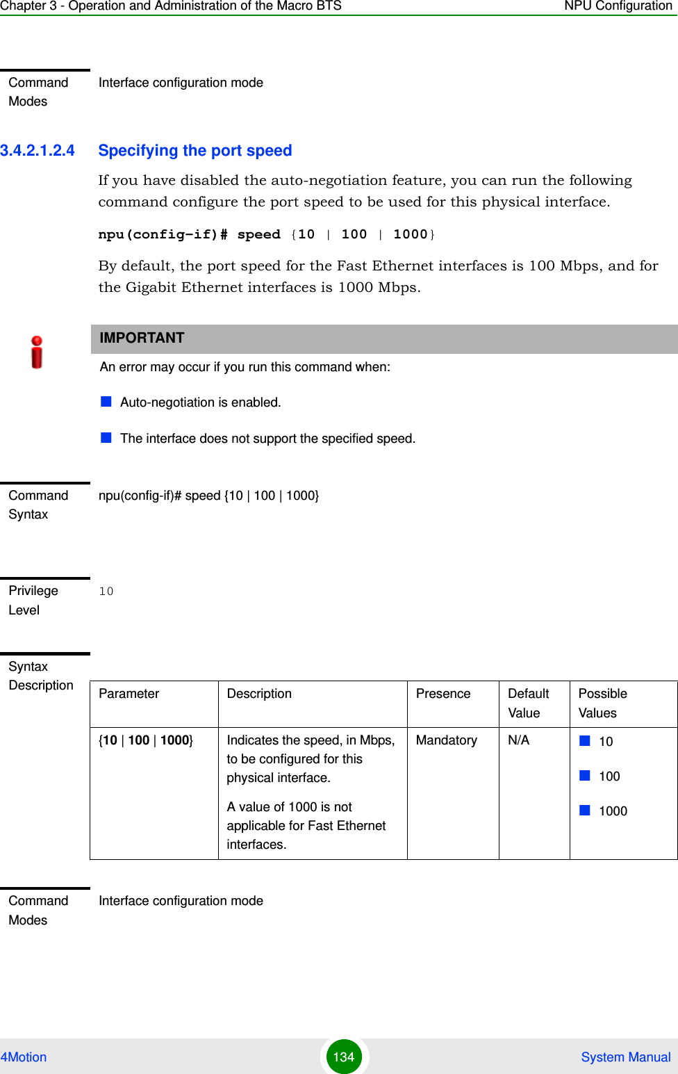
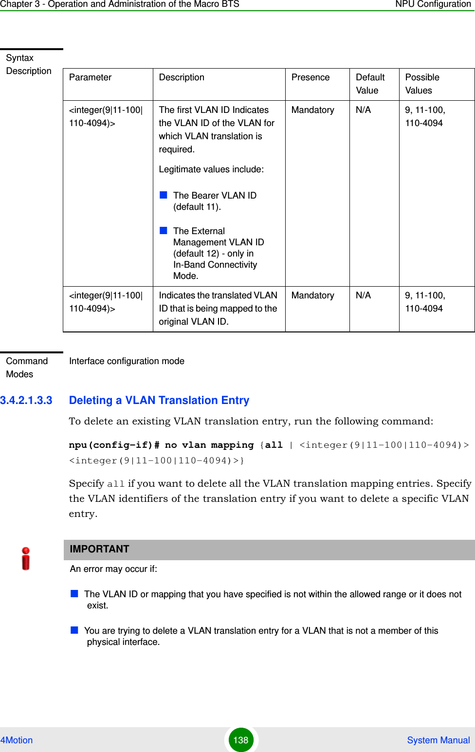
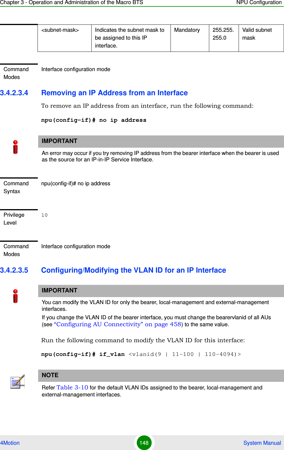
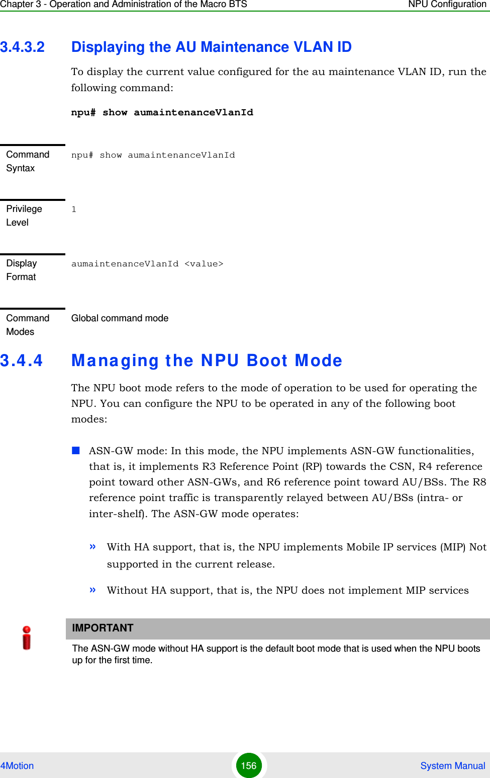
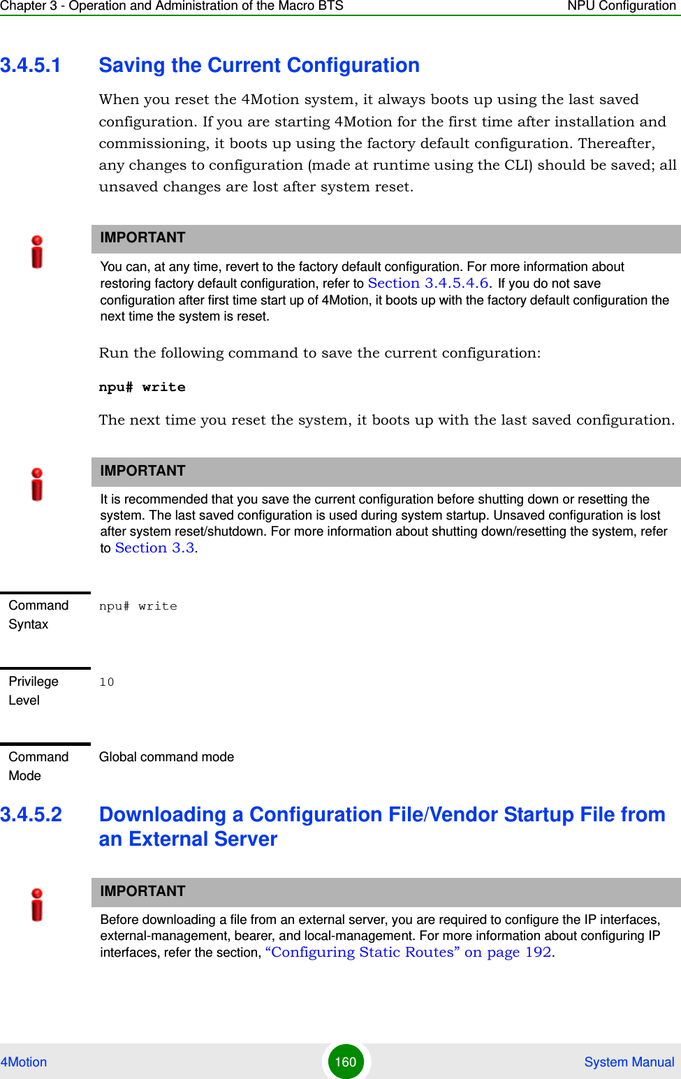
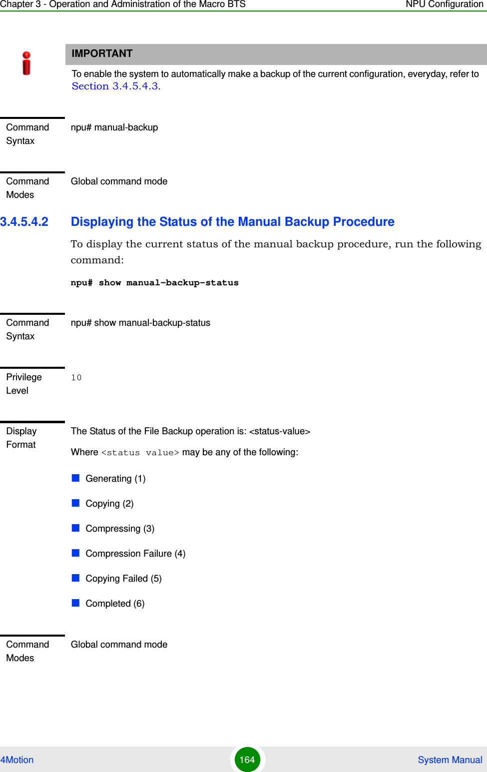
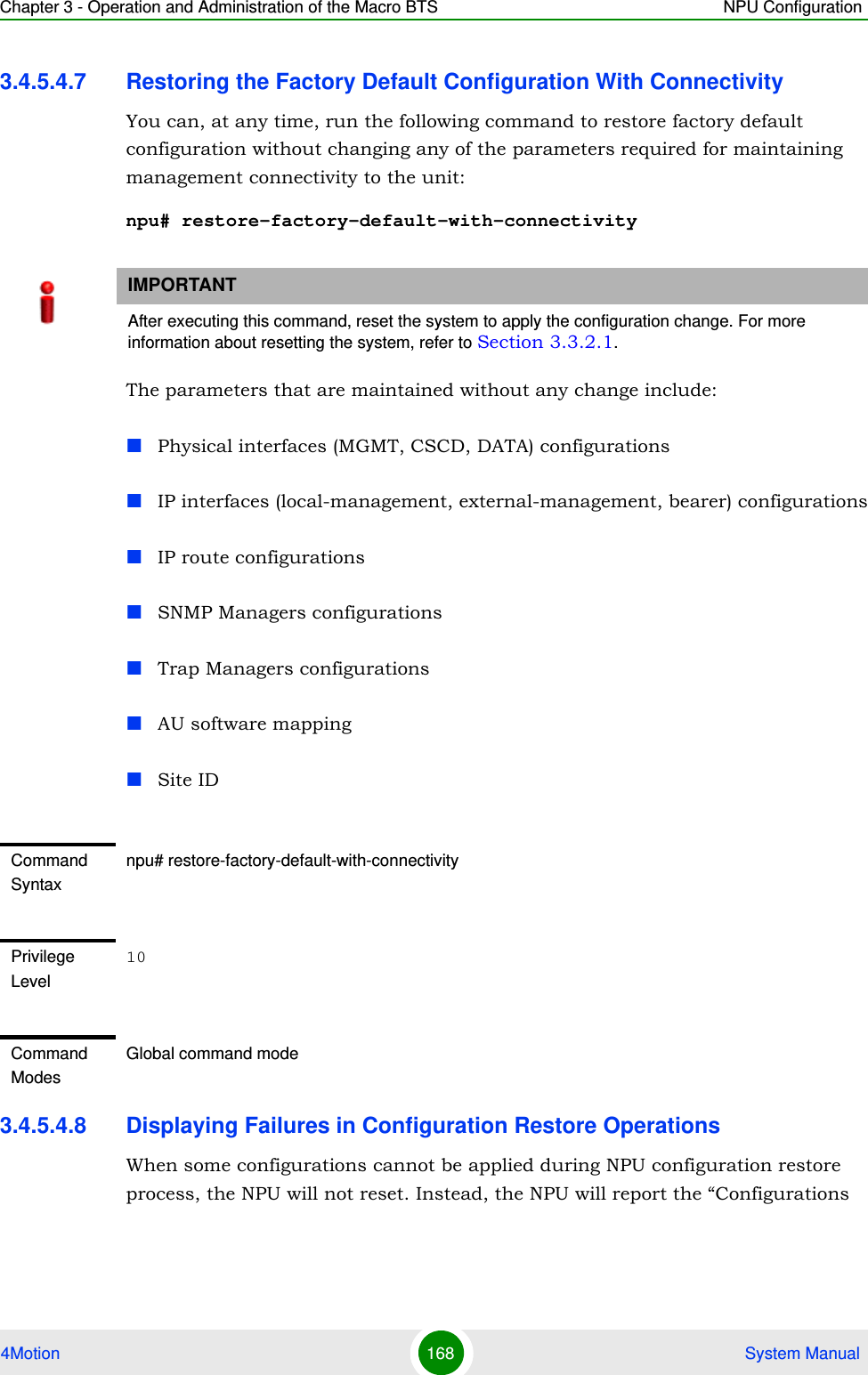
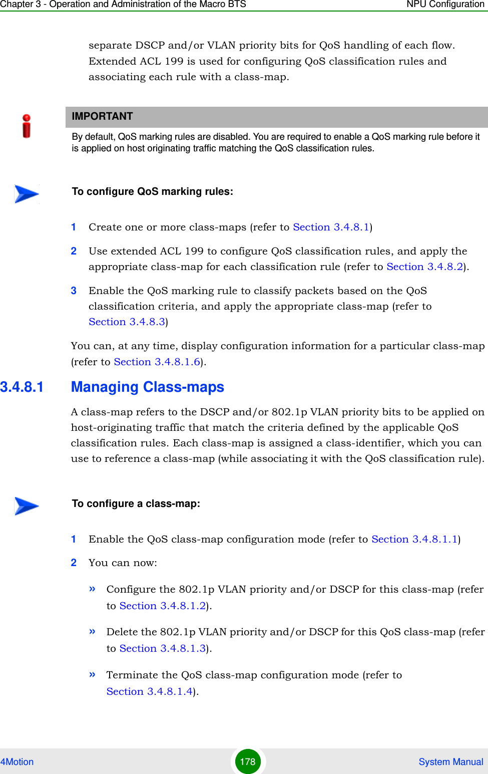
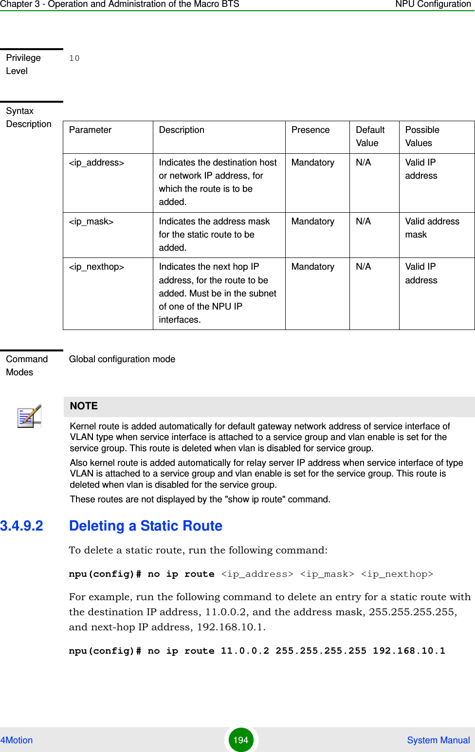
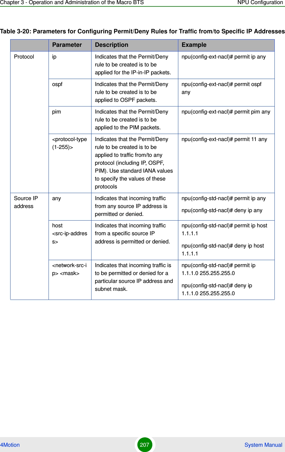
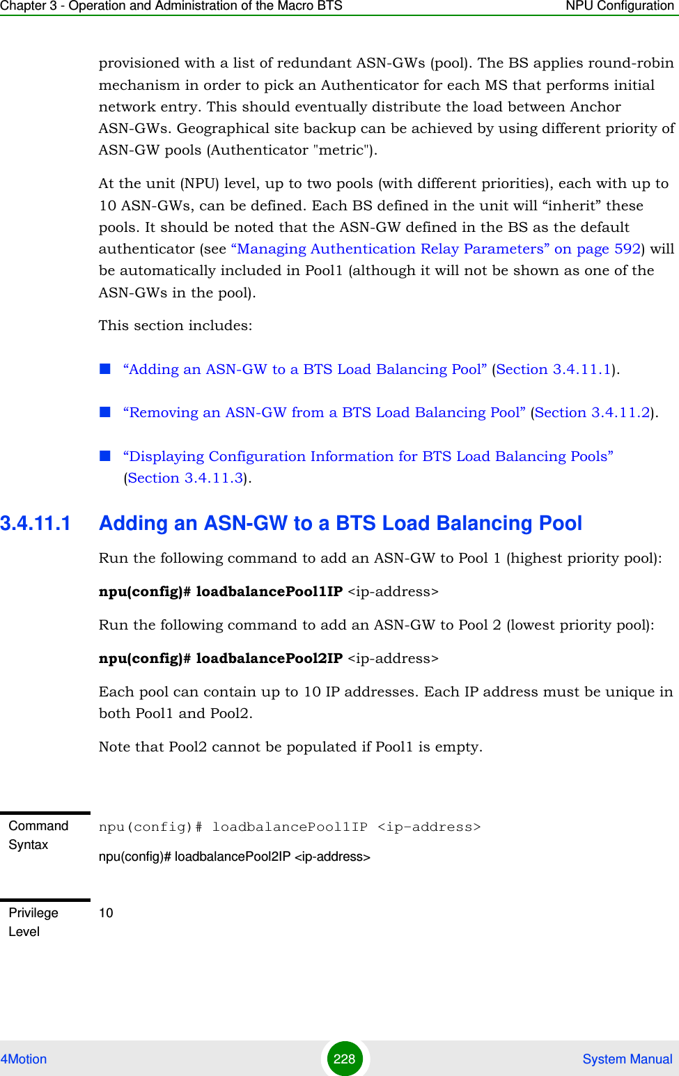
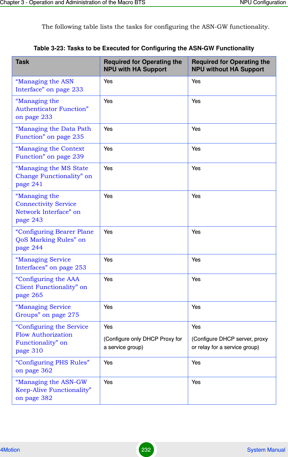
![Chapter 3 - Operation and Administration of the Macro BTS Managing Software Upgrade4Motion 107 System Manual3.2.3.1 Procedure for Upgrading the AU“Step 1: Configuring the TFTP Server” on page 107“Step 2: Downloading the AU Image to the NPU Flash” on page 108“Step 3: Creating the AU-to-Image Mapping” on page 109“Step 4: Downloading the Image to the AU Flash” on page 110“Step 5: Resetting and Rebooting the AU with the Shadow Image” on page 1113.2.3.1.1 Step 1: Configuring the TFTP ServerTo create an AU-to-image mapping, you need to first configure the TFTP server to be used for downloading the image to the NPU flash. Run the following command to configure the TFTP server to be used for software version download.IMPORTANTBefore inserting an AU card, ensure that an AU-to-image mapping exists, which is to be used for booting the AU. If you insert the AU card when there is no existing mapping, the AU is immediately shut down. For more information about creating a (default) AU-to-image mapping, refer “Step 3: Creating the AU-to-Image Mapping” on page 109.After you create the AU-to-image mapping, execute the following command (for details refer Section 3.2.3.1.5).npu(config)# reboot au [<au slot-id>] shadow [<shadow image name>]After you execute this command, the AU boots up with the mapped image.To execute the AU upgrade procedure:IMPORTANTIf you are inserting/re-inserting the AU card, you are required to execute this procedure before inserting and powering up the AU card. If an error occurs while booting up of the AU, it is reset upto three times, after which it is completely shut down.IMPORTANTThe same TFTP server is used for downloading the software image to be used for upgrading the NPU/AU. For detailed information about the configuring the TFTP server, refer Section 3.2.2.1.1.](https://usermanual.wiki/Alvarion-Technologies/MICRO-25.Manual-p2/User-Guide-1329243-Page-7.png)
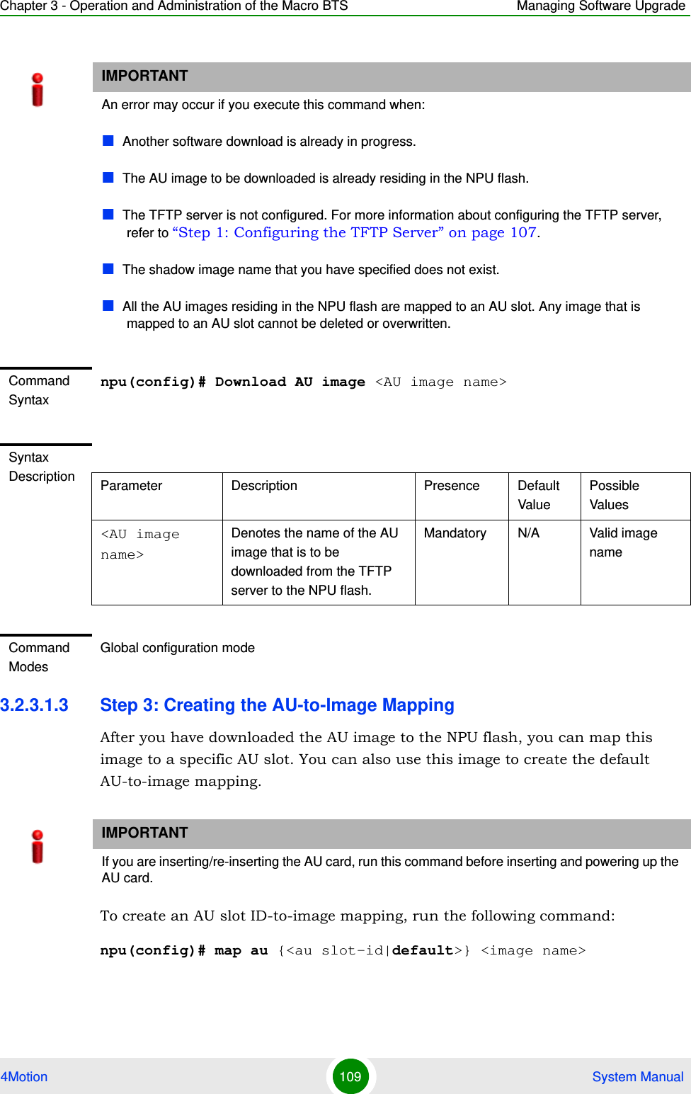
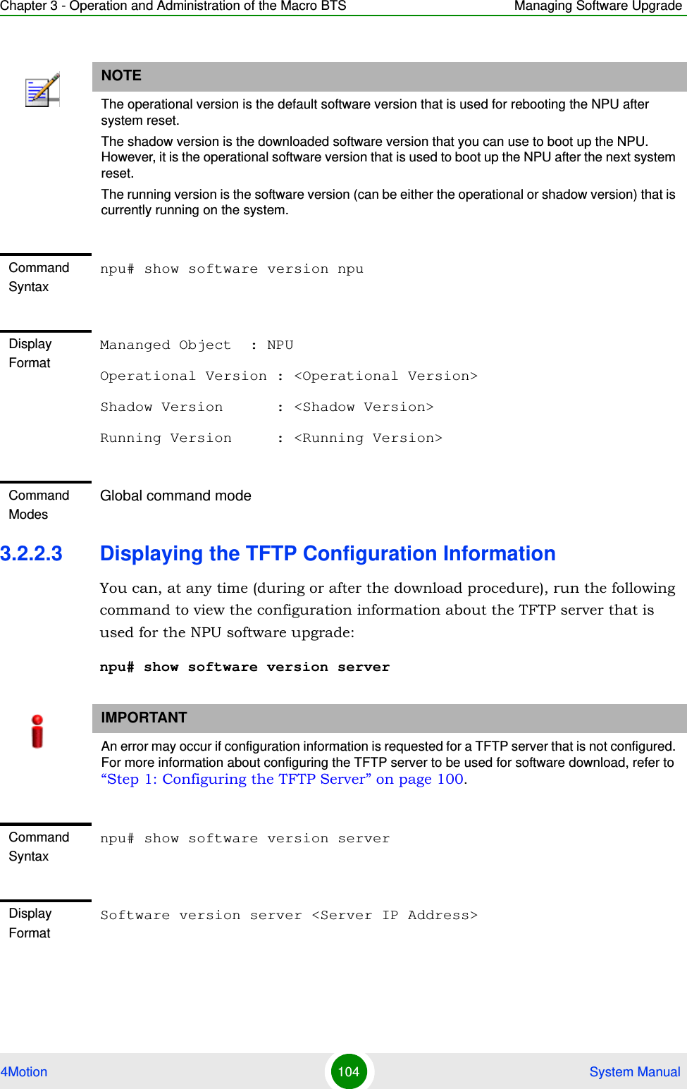
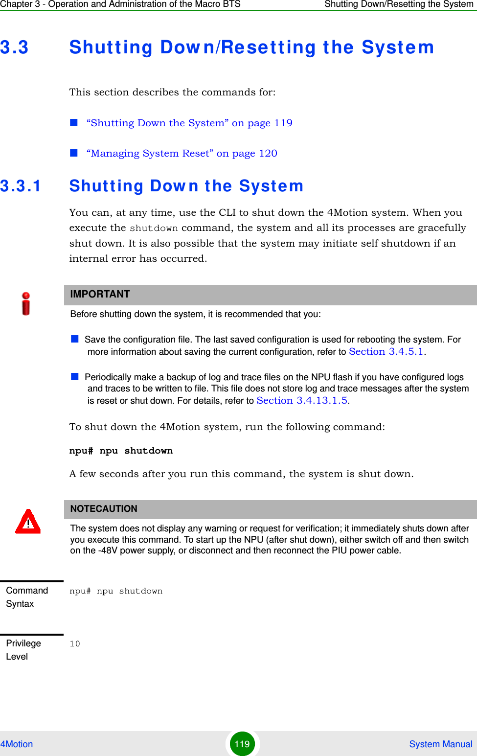
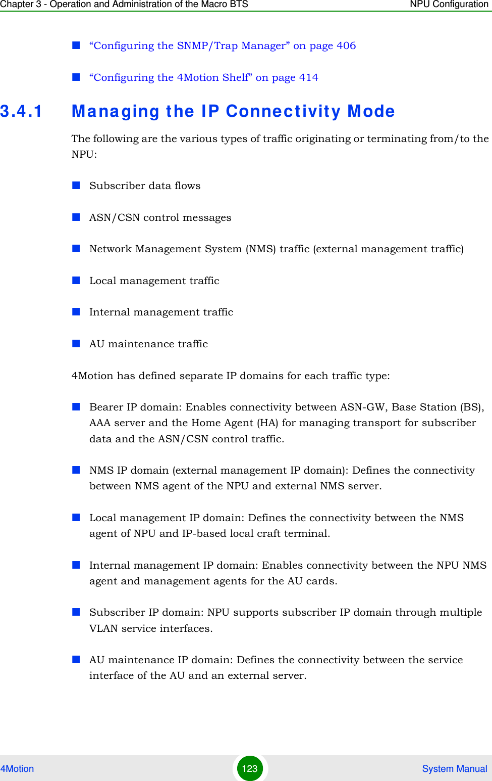
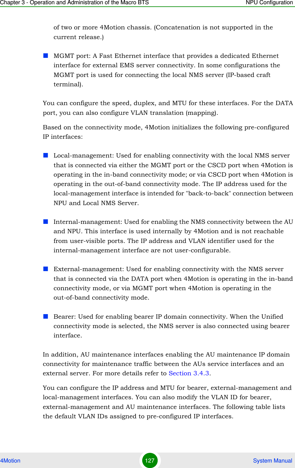
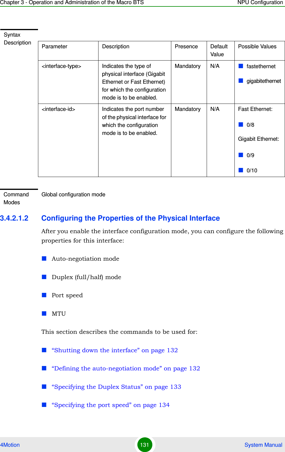
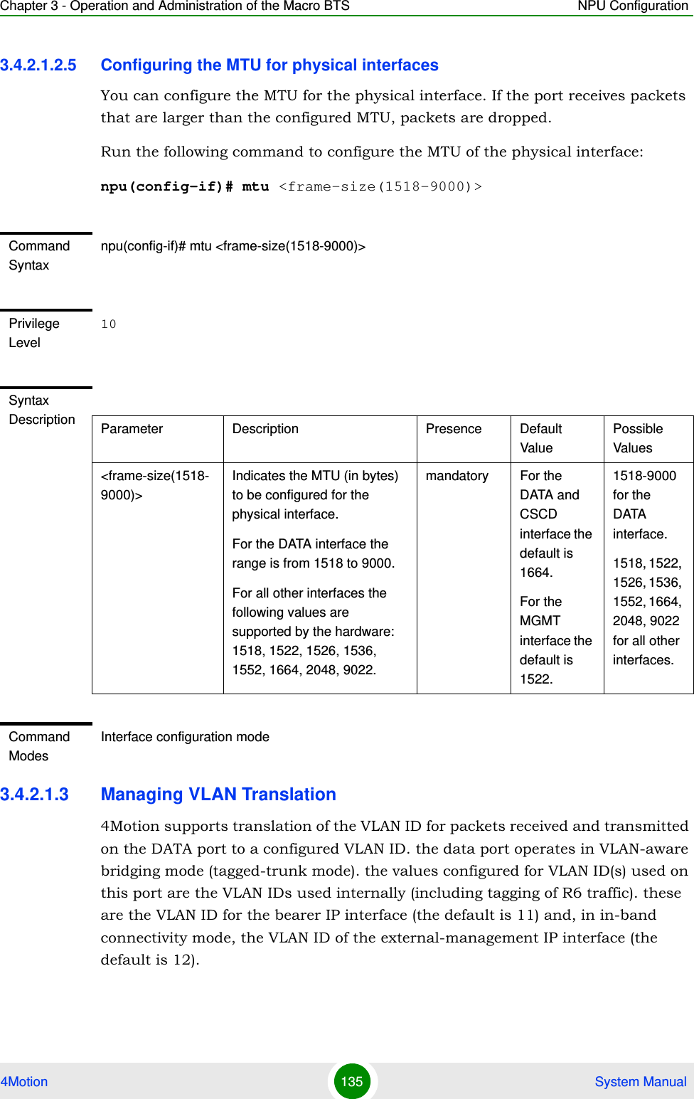
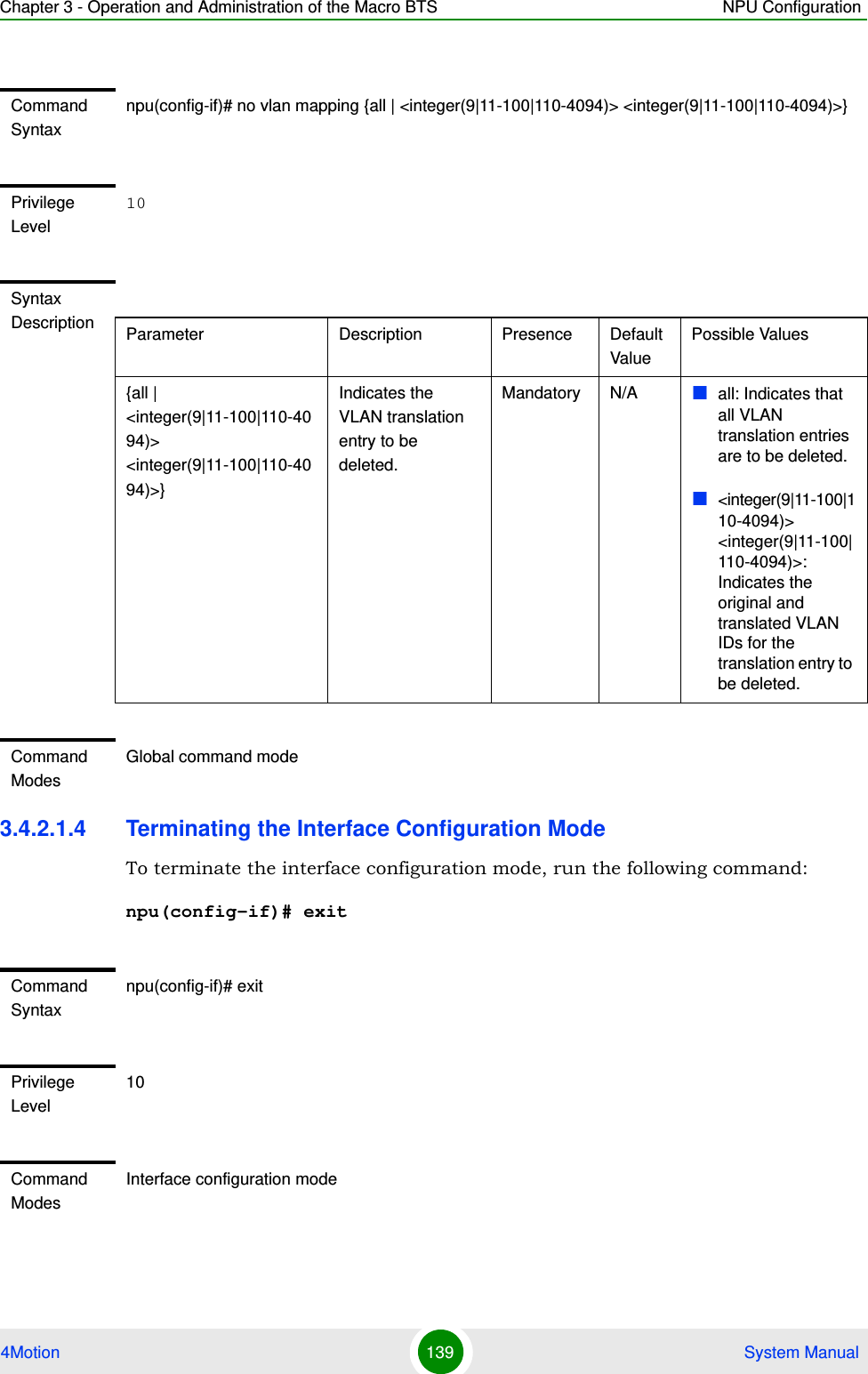
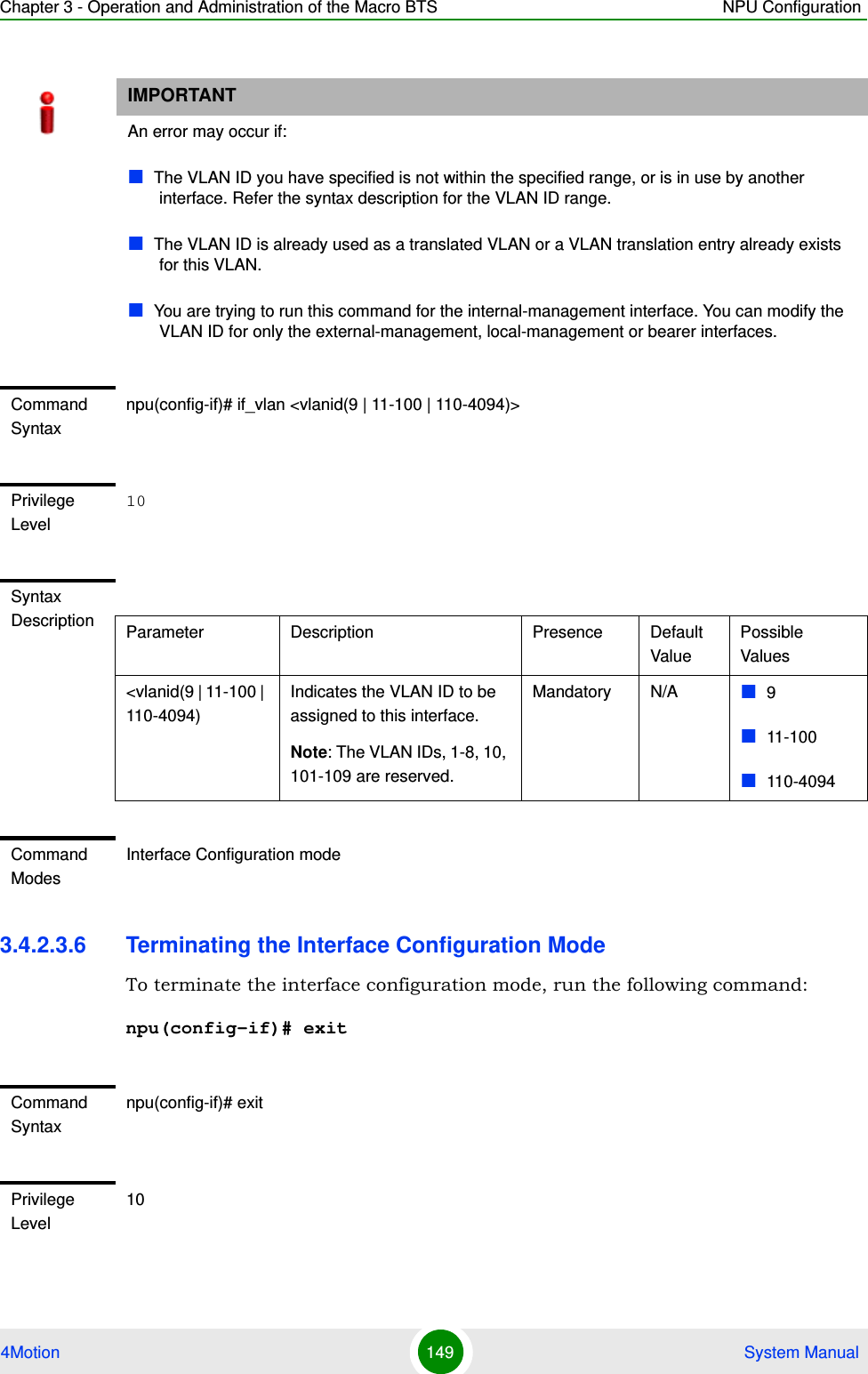
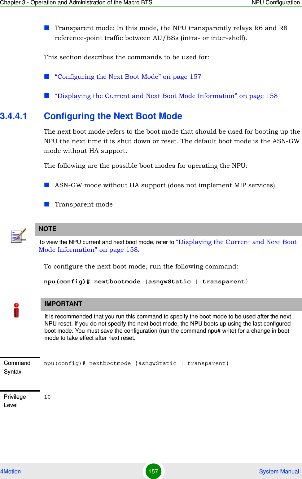
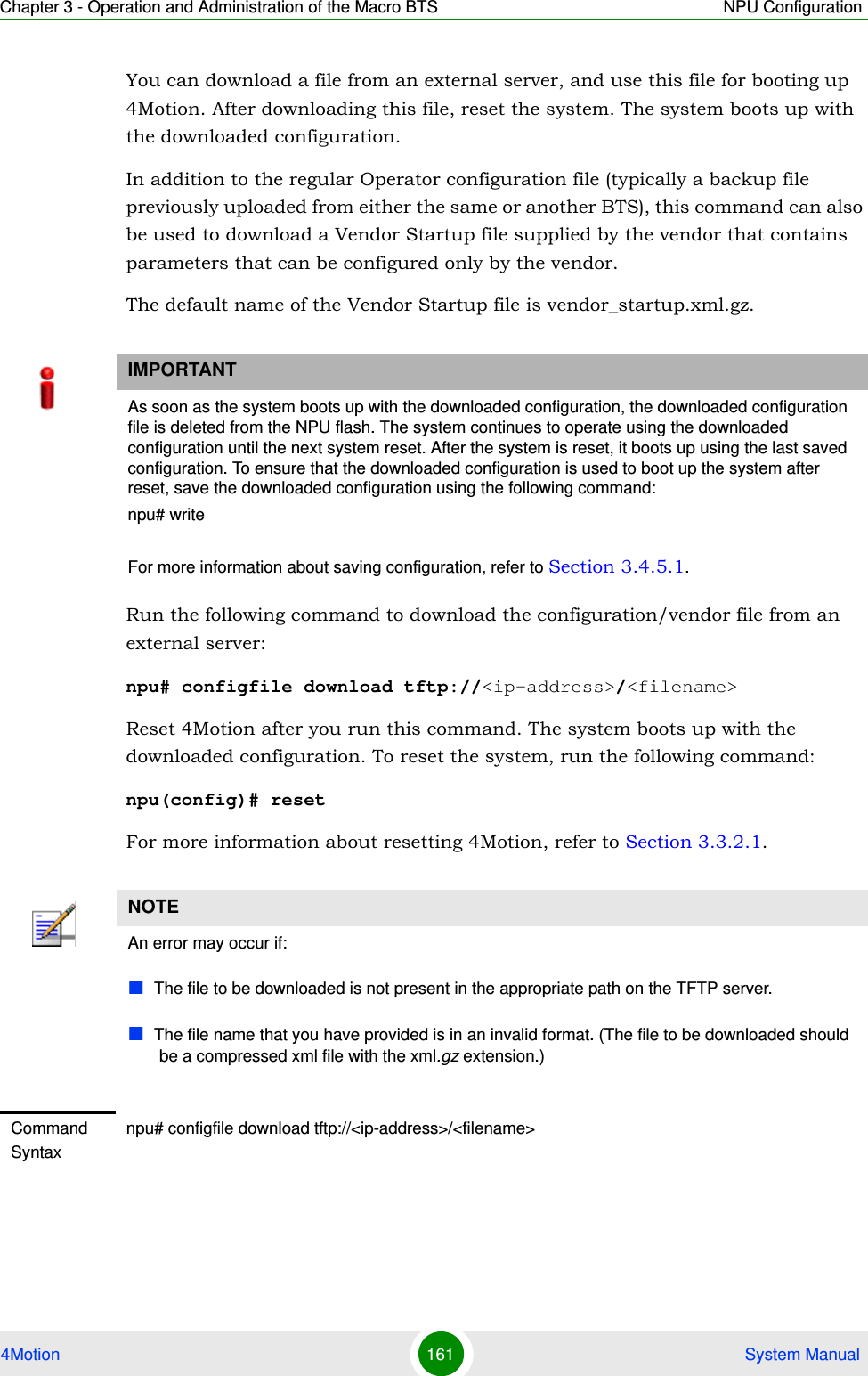
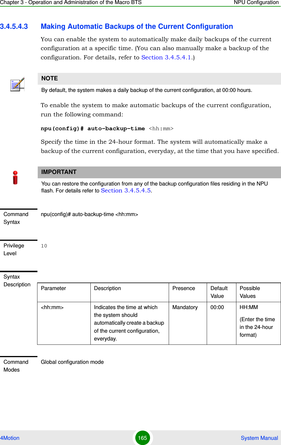
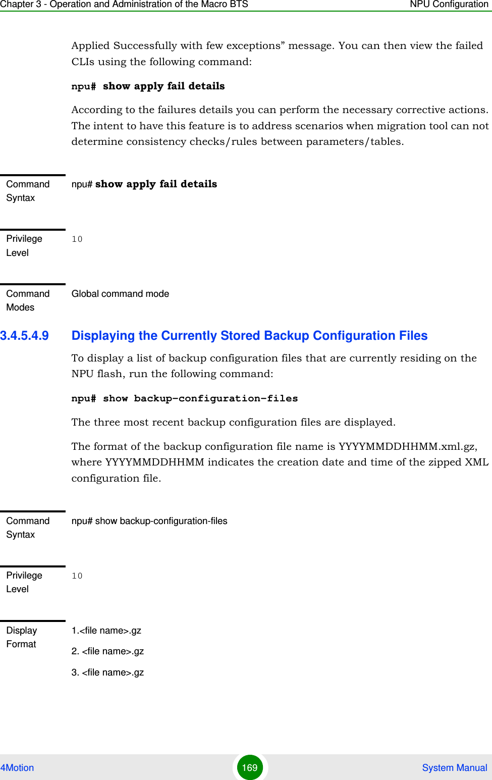
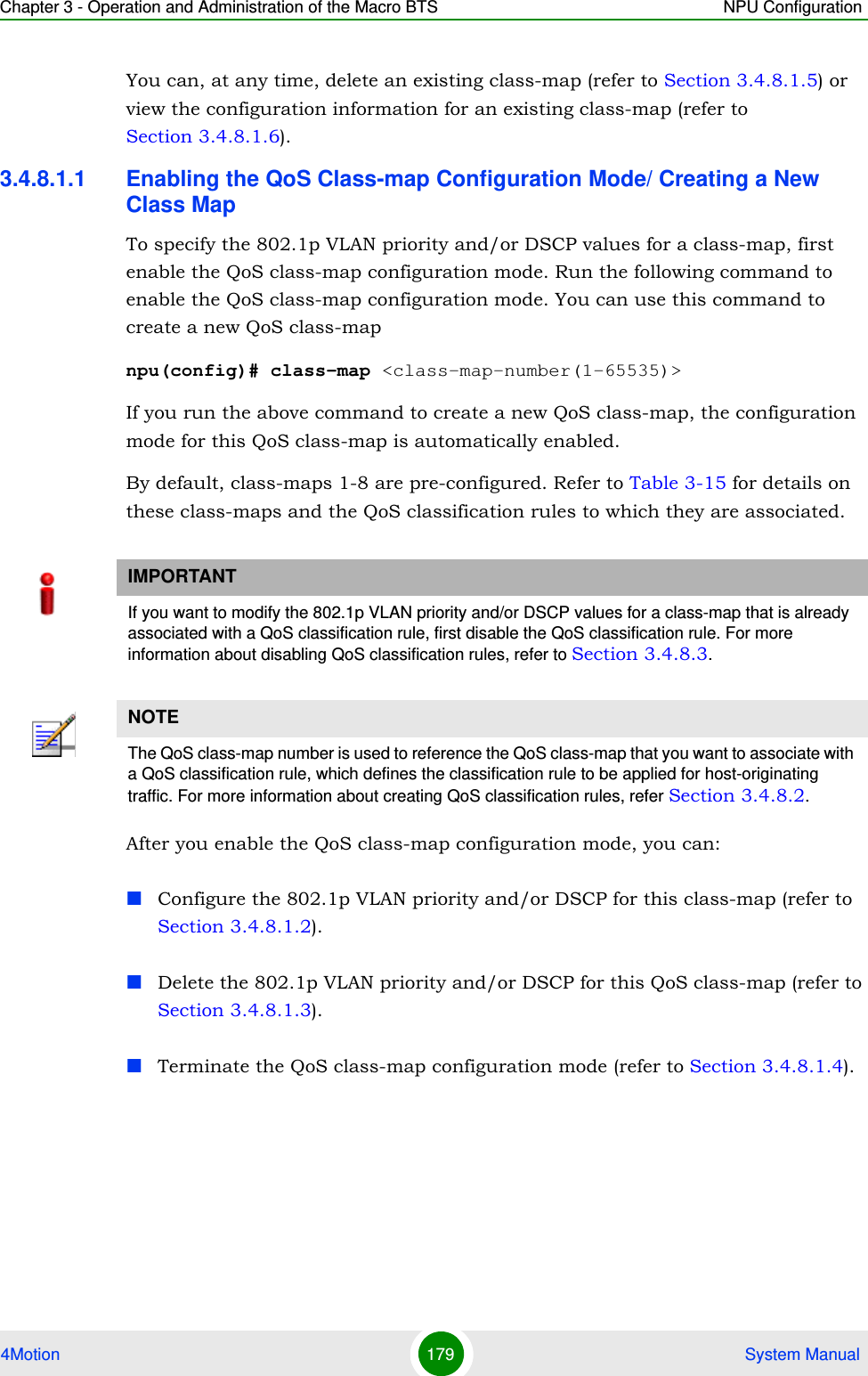
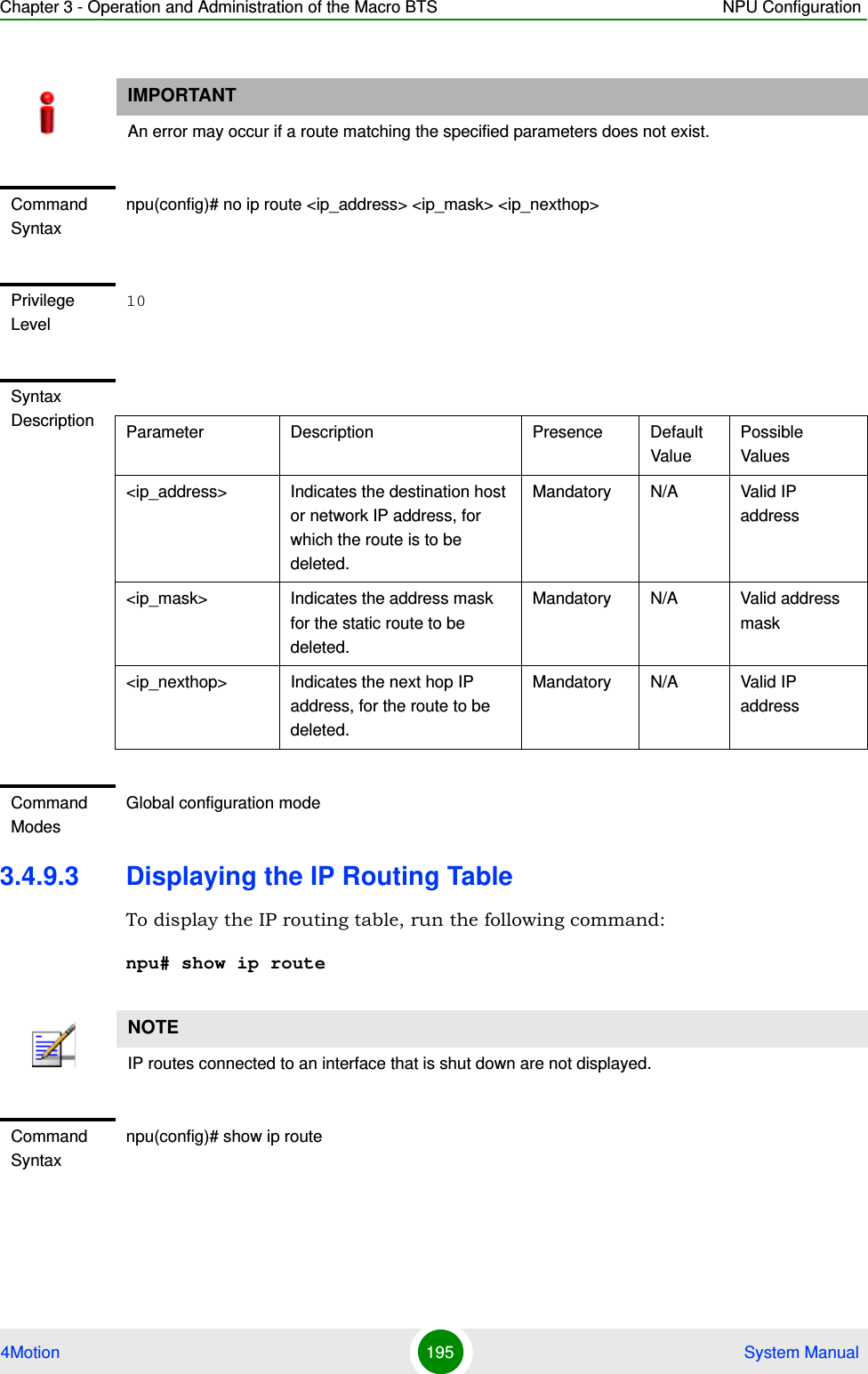
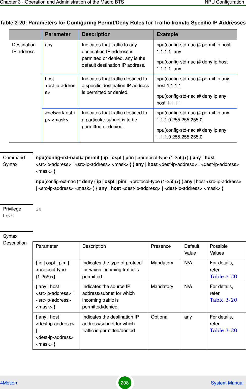
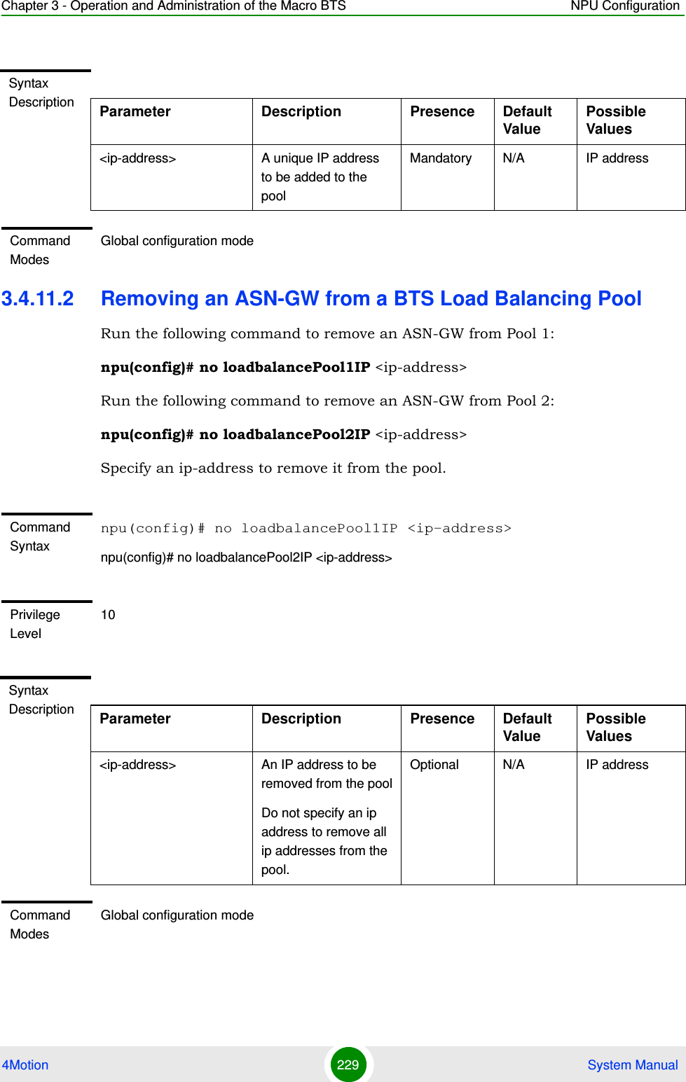
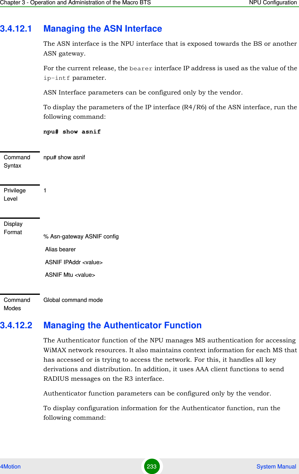
![Chapter 3 - Operation and Administration of the Macro BTS Managing Software Upgrade4Motion 111 System ManualAfter you have created the AU-to-image mapping for a particular AU slot, download the image from the NPU flash to the AU flash. To download the image to the AU flash, run the following command.npu(config)# load to au [<au slot-id>] shadow <shadow image name>3.2.3.1.5 Step 5: Resetting and Rebooting the AU with the Shadow ImageAfter you have downloaded the image to the AU flash, you can run the following command to reset the system and boot the AU with the shadow image. After you run the following command, the shadow image is used to boot the AU after it is reset. IMPORTANTAn error may occur if:The AU image is not present in the NPU flashYou execute this command immediately after inserting the AU card, and it is still registering itself with the 4Motion system.An AU image is currently being downloaded to the AU flash.The AU software image version is incompatible with the AU hardware.Command Syntaxnpu(config)# load to au [<au slot-id>] shadow <shadow image name>Syntax Description Parameter Description Presence Default ValuePossible Value[<au slot-id>] Indicates the slot ID of the AU to which the image is to be downloaded from the NPU flash.Optional N/A 1, 2, 3, 4, 7, 8, 9 (Valid slot ID)shadow <shadow image name>Denotes the name of the shadow image to be downloaded from the NPU to the AU flash.Optional N/A Valid image nameCommand ModesGlobal configuration mode](https://usermanual.wiki/Alvarion-Technologies/MICRO-25.Manual-p2/User-Guide-1329243-Page-11.png)
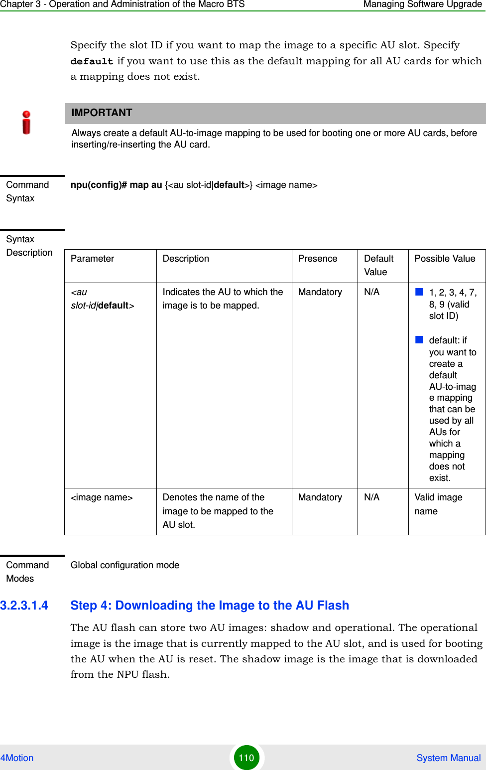
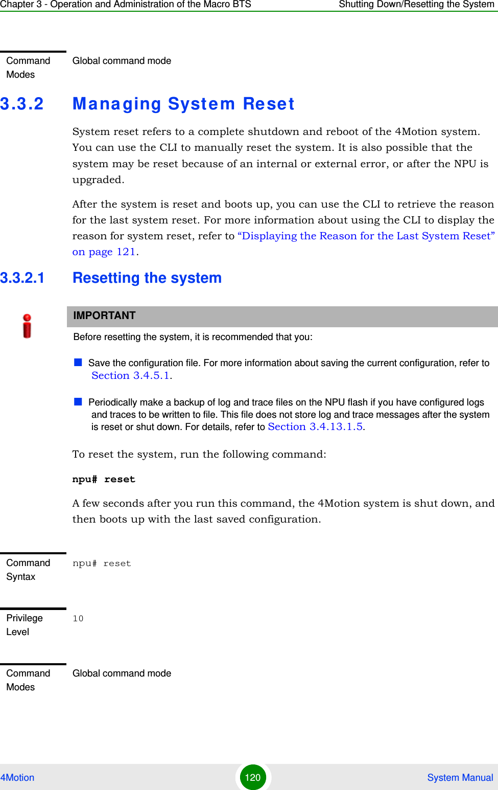
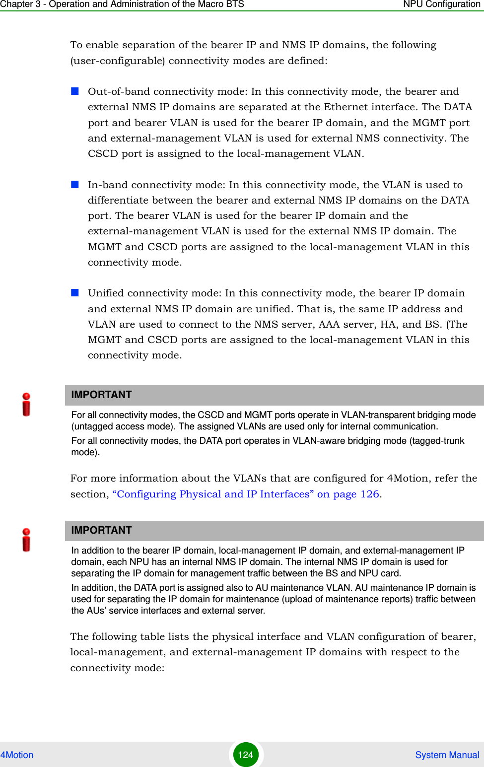
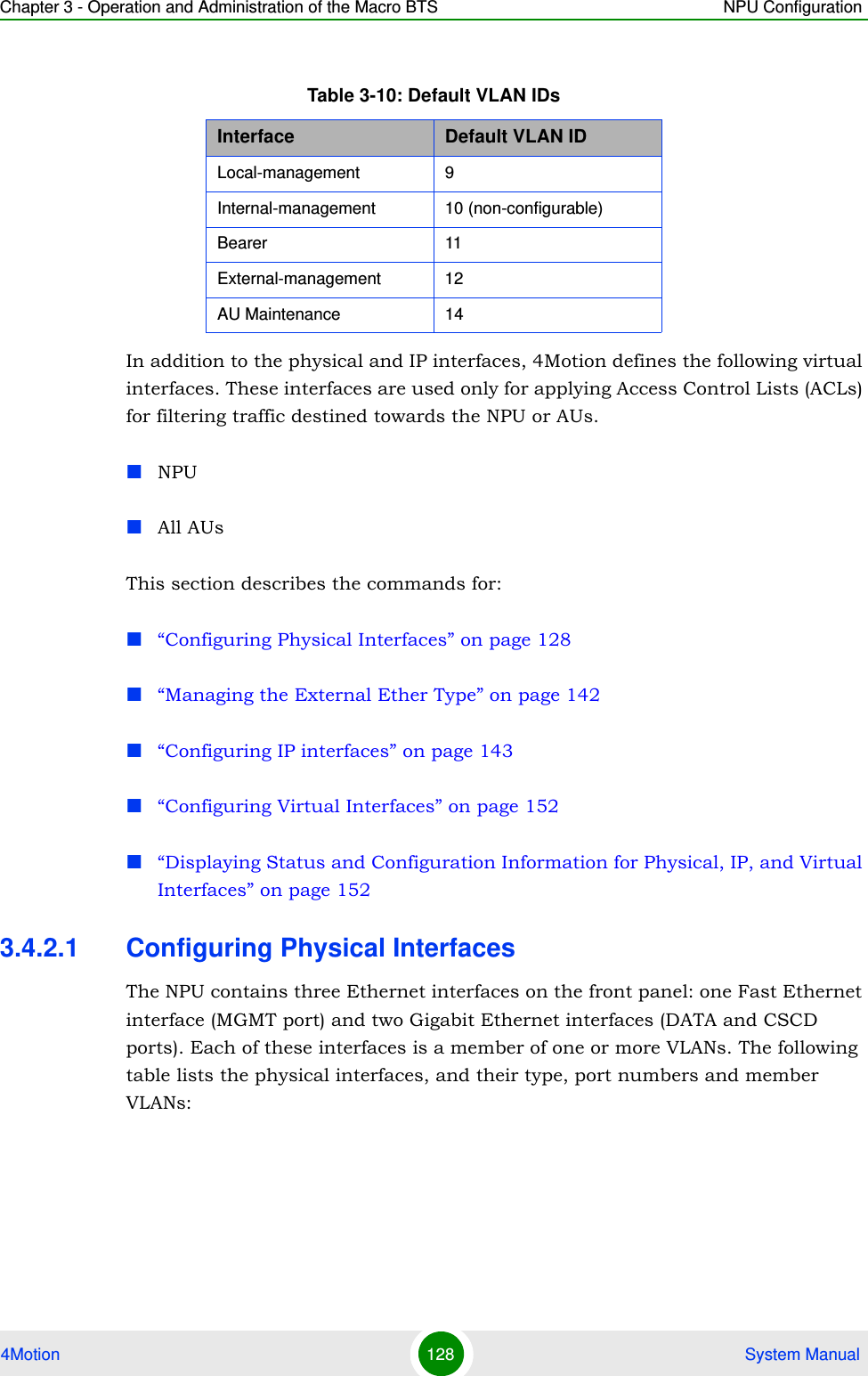
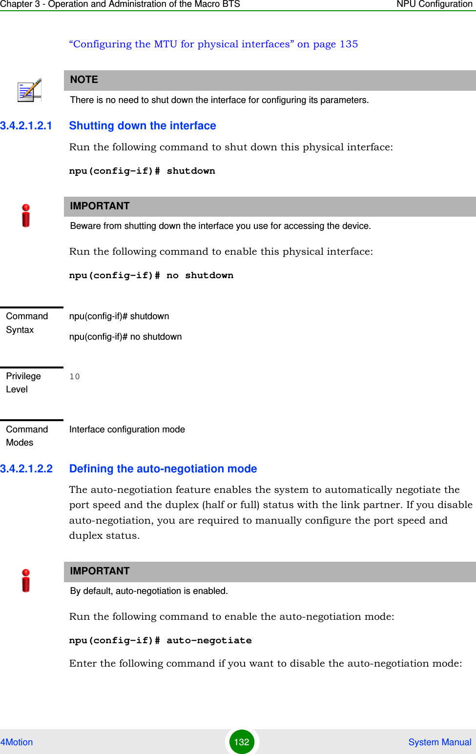
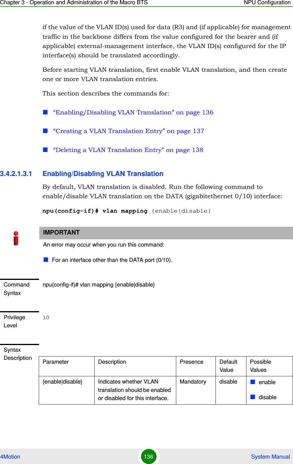
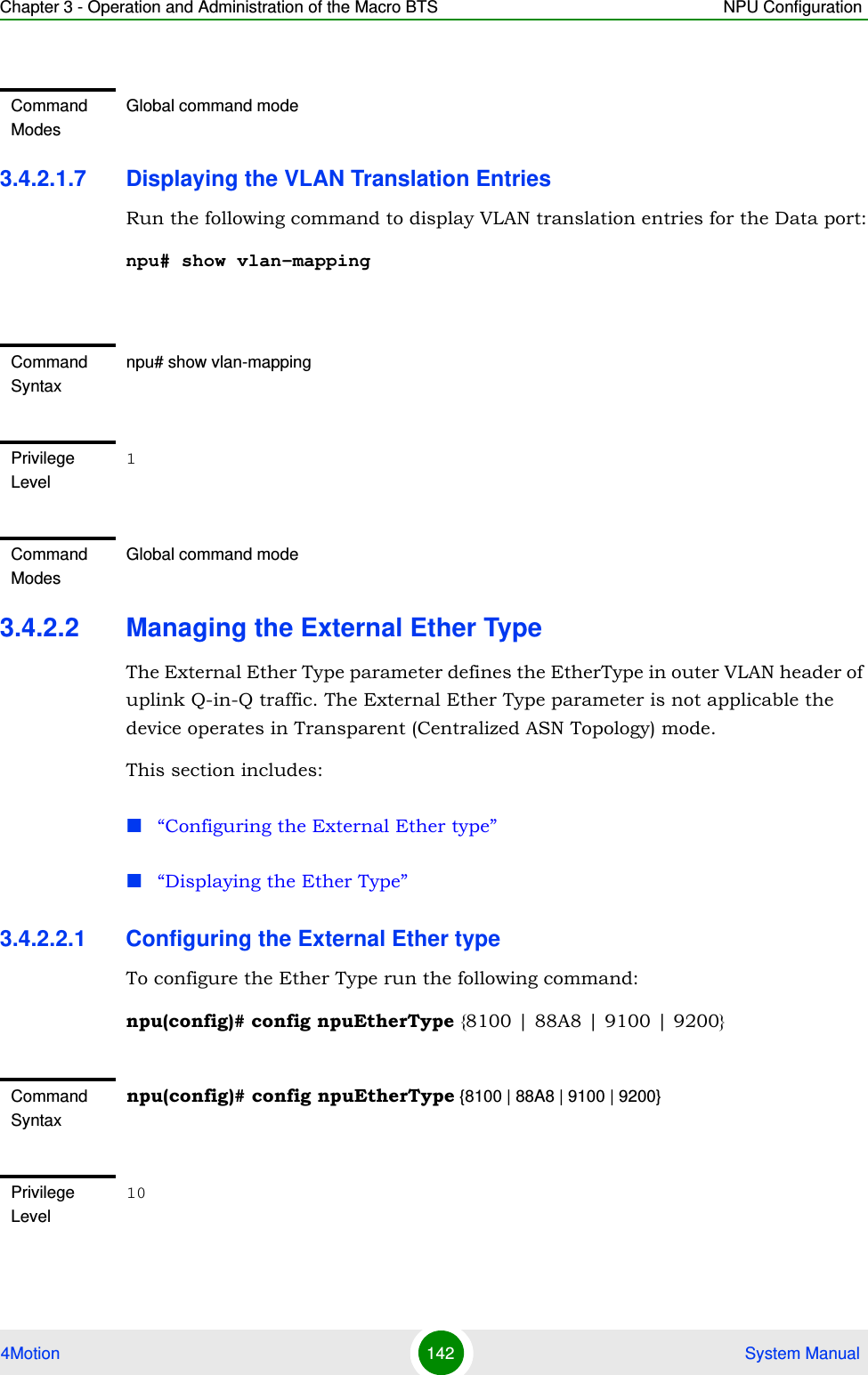
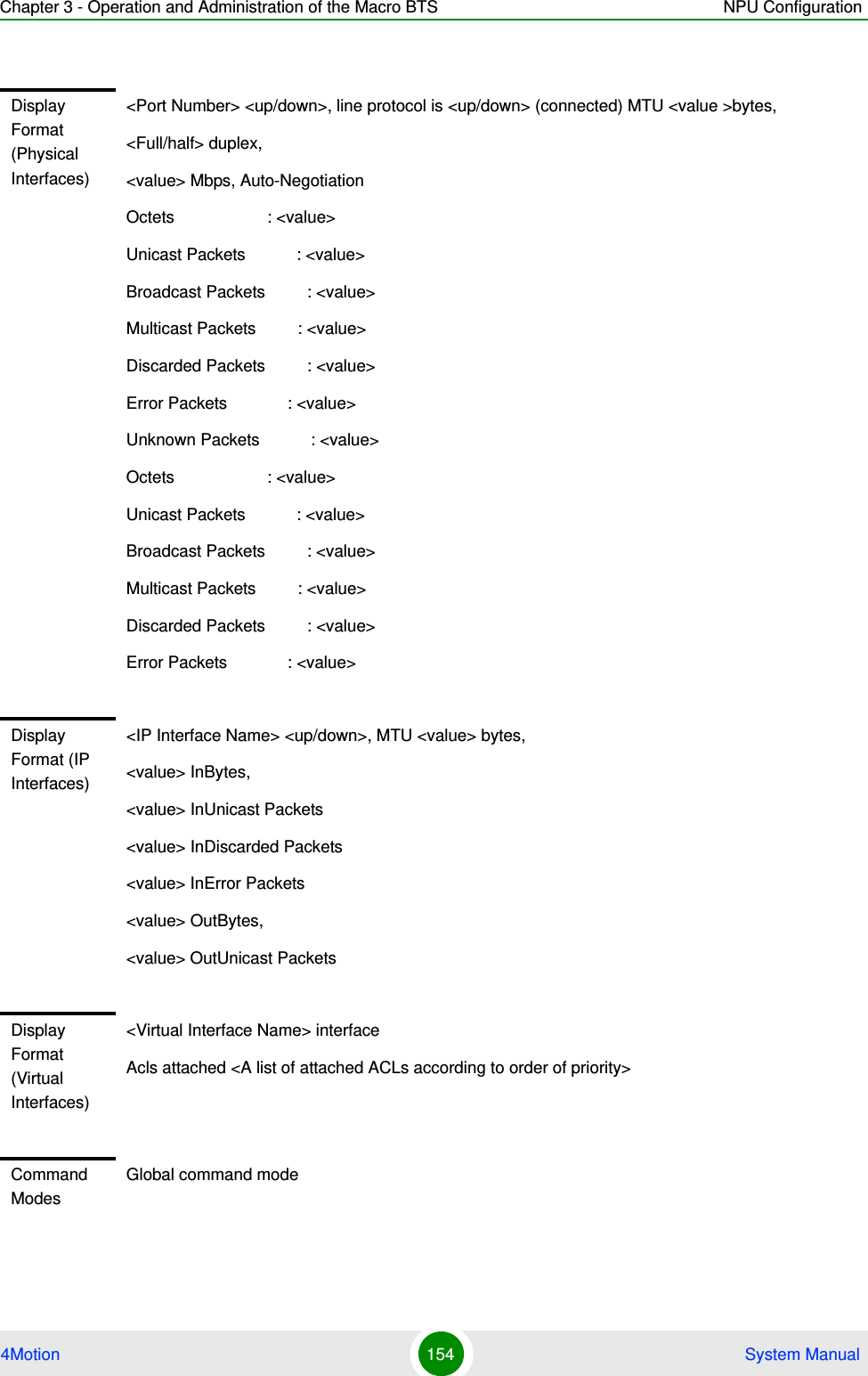
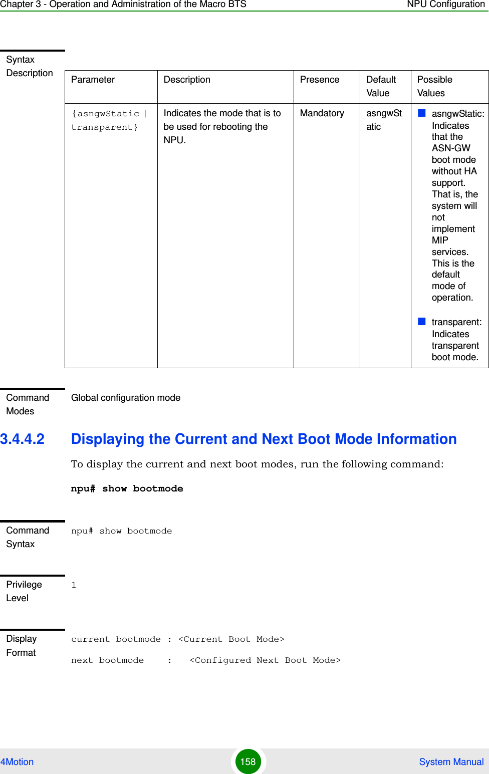
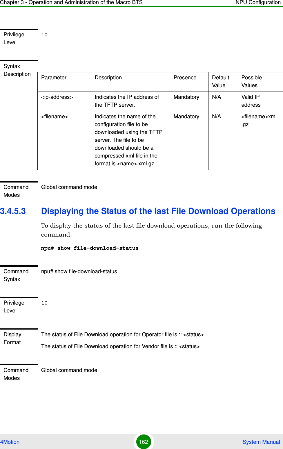
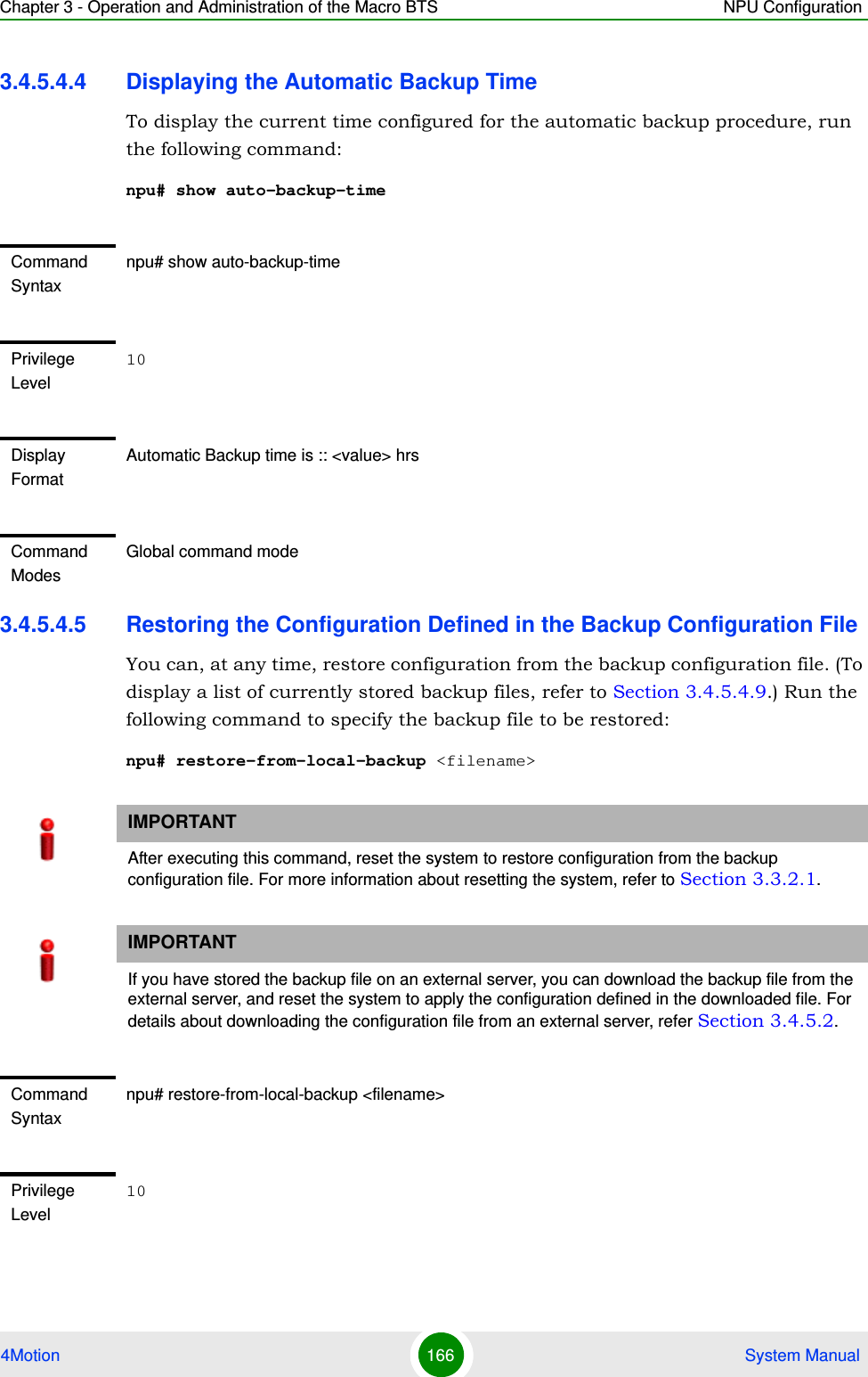
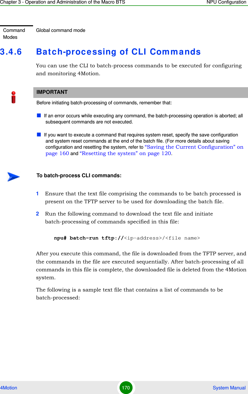
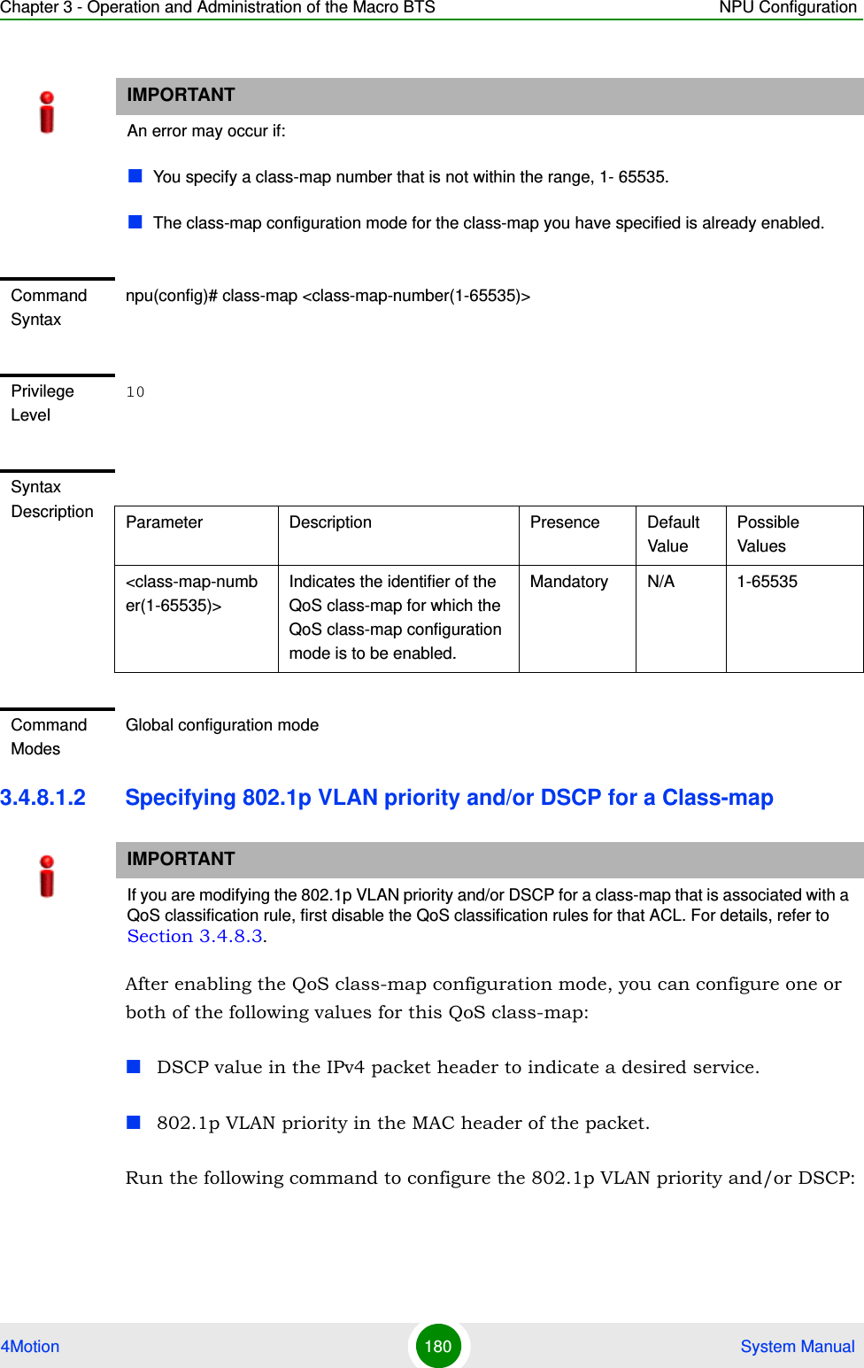
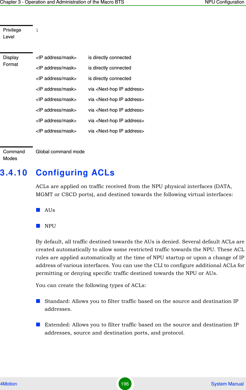
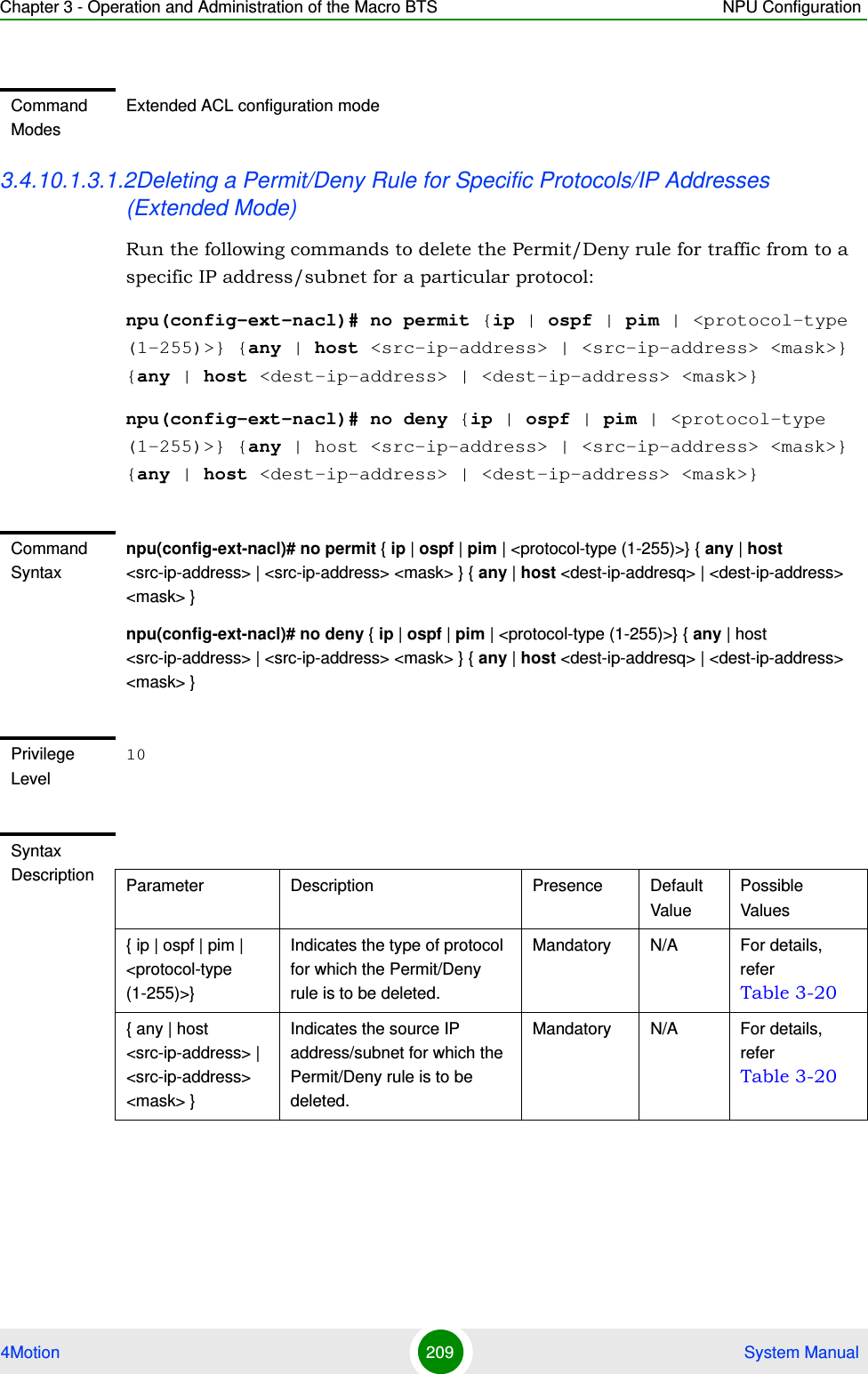
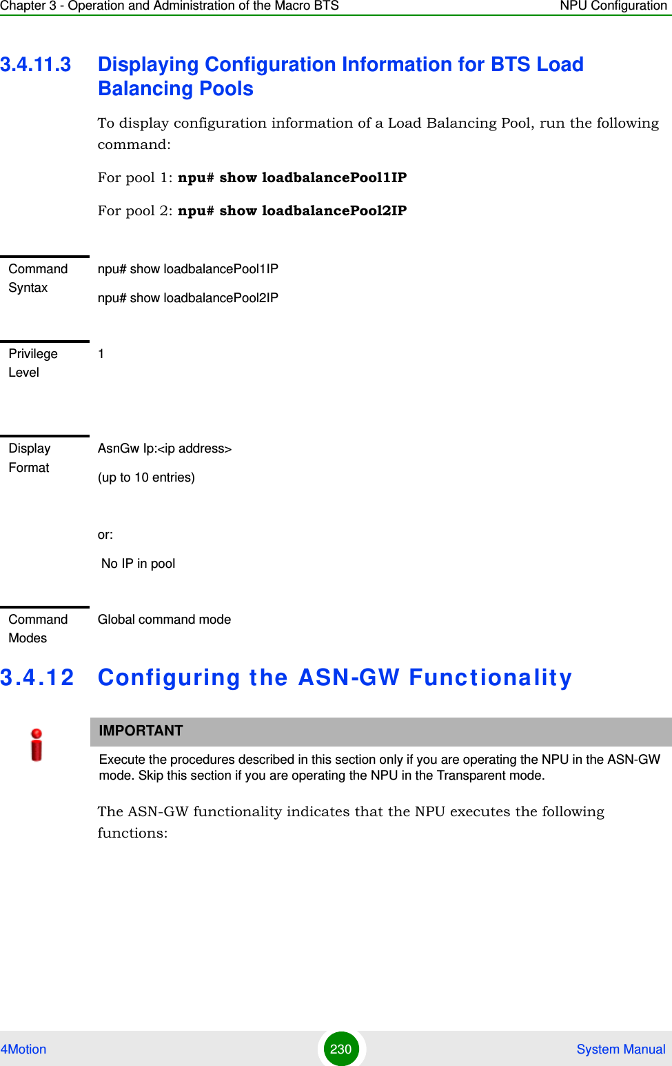
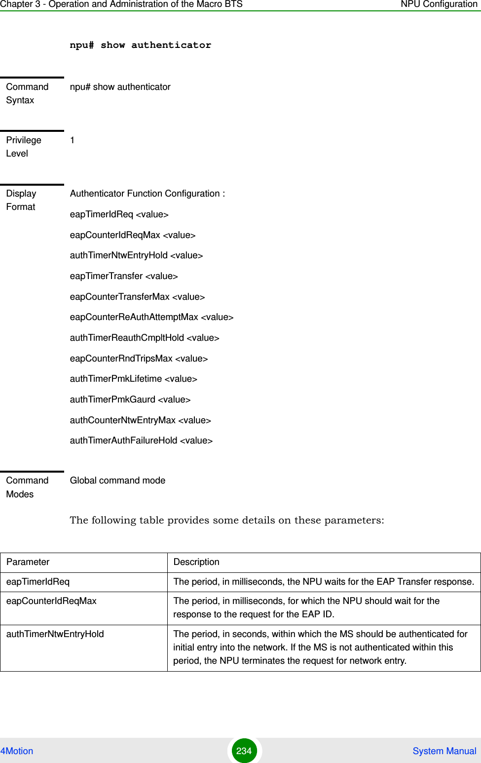
![Chapter 3 - Operation and Administration of the Macro BTS Managing Software Upgrade4Motion 112 System ManualIf the AU is successfully rebooted with the shadow image, then this image becomes the operational image for AU. If an error occurs in booting up the AU with the shadow image, the AU boots up with the operational image instead. However, the AU is immediately shut down after it boots up with the operational image.npu(config)# reboot au [<au slot-id>] shadow <shadow image name>Specify the image name that you have used for creating the mapping in, “Step 3: Creating the AU-to-Image Mapping” on page 109. If you define another image name in this command, the AU-to-image mapping is updated with this image (provided this image is also residing in the NPU flash). Specify the slot ID if you want to reboot a specific AU slot with this image. If you want to reboot all the AU slots with this image, do not specify any slot ID. In addition, the mappings for all AUs are updated with this image.After you run this command, the software version that is used to reboot the AU is the operational version. This version will be used for rebooting after the next AU reset.IMPORTANTAn error may occur if:The AU image is not present in the NPU flash. You execute this command immediately after inserting the AU card, and it is still registering itself with the 4Motion system.The software image version is incompatible with the hardware.Rebooting the AU with the shadow image has failed. (The AU boots up with the operational image, and then initiates self-shut down.IMPORTANTDo not delete this image from the NPU flash because this image is used to boot up the AU the next time it is reset. If you delete this image from the NPU flash, the default AU-to-image mapping will be used to reboot the AU.Command Syntaxnpu(config)# reboot au [<au slot-id>] shadow <shadow image name>](https://usermanual.wiki/Alvarion-Technologies/MICRO-25.Manual-p2/User-Guide-1329243-Page-12.png)
![Chapter 3 - Operation and Administration of the Macro BTS Managing Software Upgrade4Motion 113 System Manual3.2.3.2 Displaying the Shadow, Running, and Operational VersionsYou can, at any time (during or after the software download procedure), run the following command to view the shadow, running, and operational versions used for the AU:npu# show software version au [<au slot-id>]Specify the AU slot ID, if you want to view the software version for a specific AU slot. Do not specify the AU slot ID if you want to view the software versions used for all AU slots.Syntax Description Parameter Description Presence Default ValuePossible Value[<au slot-id>] Denotes the slot ID of the AU to be rebooted with the image residing in the AU flash.If you do not specify a value for this parameter, the image is used to reboot all AUs.Optional N/A 1, 2, 3 4, 7, 8, 9<shadow image name>Denotes the name of the AU image to be used for rebooting the AU. If you do not specify the name of the shadow image, the AU reboots with the shadow image residing in the AU flash.Mandatory N/A Valid shadow image nameCommand ModesGlobal configuration modeNOTEThe operational version is the default software version that is used for rebooting the AU after AU reset. The shadow version is the downloaded software version that you can use to boot the AU. However, the next time the system is reset, it is the operational software version that is used to boot the NPU.The running version is the software version (is either the operational or shadow version) that is currently running on the system.](https://usermanual.wiki/Alvarion-Technologies/MICRO-25.Manual-p2/User-Guide-1329243-Page-13.png)
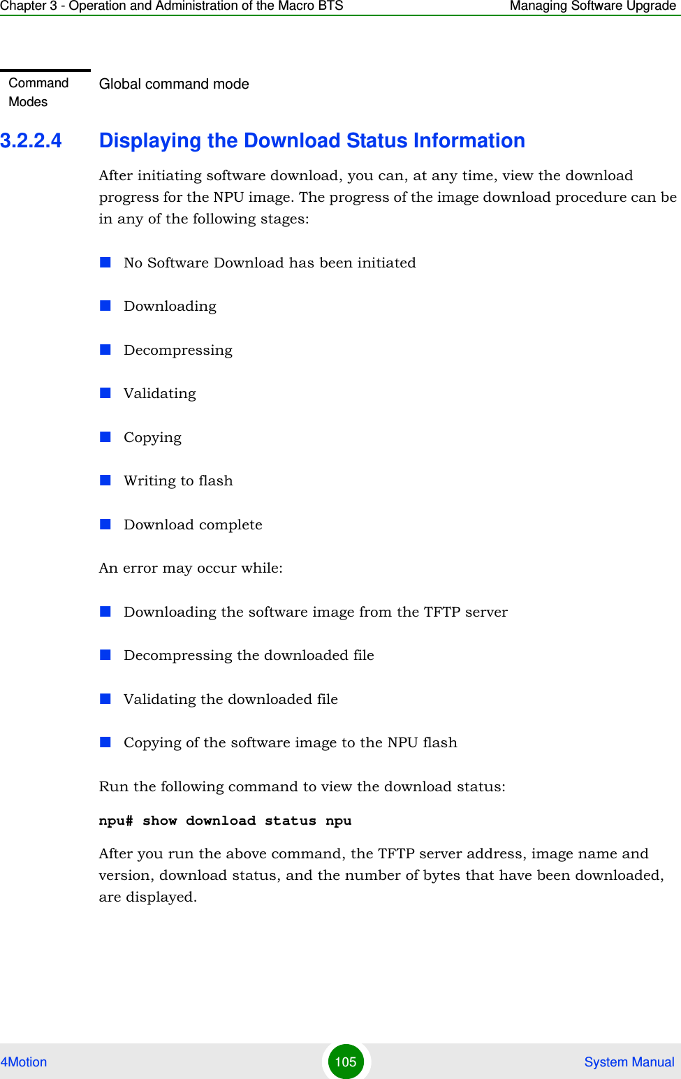
![Chapter 3 - Operation and Administration of the Macro BTS Managing Software Upgrade4Motion 114 System Manual3.2.3.3 Displaying the Download Status InformationAfter initiating software download, you can, at any time, view the download progress for the AU image to the NPU flash. The progress of image download can be in any of the following stages:DownloadingValidatingCopyingCommand Syntaxnpu# show software version au [<au slot-id>]Syntax Description Parameter Description Presence Default ValuePossible Value[<au slot-id>] Indicates the AU slot ID for which information about the shadow, operational, and running images is to be displayed.If you do not specify a value for this parameter, information about the shadow, operational, and running images for all AUs is displayed.Optional N/A 1, 2 3, 4, 7, 8, 9Command ModesGlobal command modeDisplay FormatMananged Object : AUAU Slot-ID : <au slot-d>Operational Version : <oper_ver>Shadow Version : <shaow_ver>Running Version : <running_ver>](https://usermanual.wiki/Alvarion-Technologies/MICRO-25.Manual-p2/User-Guide-1329243-Page-14.png)
![Chapter 3 - Operation and Administration of the Macro BTS Managing Software Upgrade4Motion 115 System ManualWriting to flashDownload completeAn error may occur while:Downloading the software image from the TFTP serverValidating the downloaded fileCopying of the software image to the NPU flashRun the following command to view the download status of the AU image to NPU flash:npu# show software download status au3.2.3.4 Displaying the AU-to-Image MappingYou can run the following command to view the AU-to-image mapping for a particular AU slot:npu# show au [{<au slot-id|default>}] mappingIMPORTANTAn error may occur if you execute this command when no download procedure is in progress.Command Syntaxnpu# show software download status auDisplay FormatMananged Object : AUImage Name : <Downloaded Image Name>Software version server : <Server IP address>Download Status : <Download Status>Download Bytes : <Download bytes>Command ModesGlobal command mode](https://usermanual.wiki/Alvarion-Technologies/MICRO-25.Manual-p2/User-Guide-1329243-Page-15.png)
![Chapter 3 - Operation and Administration of the Macro BTS Managing Software Upgrade4Motion 116 System ManualSpecify the AU slot ID to display the AU-to-image mapping for a specific AU slot. If you want to view the default AU-to-image mapping, specify default. If you do not specify the slot ID or default, all the AU-to-image mappings are displayed.3.2.3.5 Deleting the AU-to-Image MappingRun the following command to delete an existing AU-to-image mapping:npu(config)# delete au <au slot-id> mappingSpecify the AU slot ID for which you want to delete the existing mapping. After you delete this mapping, the AU boots up using the default AU-to-image mapping after the next AU reset.Command Syntaxnpu# show au [{<au slot-id|default>}] mappingSyntax Description Parameter Description Presence Default ValuePossible Value<au slot-id|default> Indicates the AU for which the AU slot to image mapping is to be displayed.If you do not specify a value for this parameter, all the AU-to-image mappings are displayed.Mandatory N/A 1, 2, 3, 4, 7, 8, 9 (Valid slot ID)default: if you want to display the default AU-to-image mappingCommand ModesGlobal command modeDisplay Format AU slot id Software image<AU slot-id> <Image Name>Command Syntaxnpu(config)# delete au <au slot-id> mapping](https://usermanual.wiki/Alvarion-Technologies/MICRO-25.Manual-p2/User-Guide-1329243-Page-16.png)
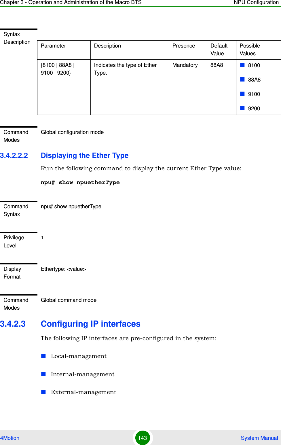
![Chapter 3 - Operation and Administration of the Macro BTS NPU Configuration4Motion 140 System Manual3.4.2.1.5 Displaying VLAN Membership InformationRun the following command to display Ethernet interfaces that are members of a particular or all VLAN:npu# show vlan [id <vlan-id(11-4094)>]Do not specify the VLAN ID if you want to view membership information for all VLANs.3.4.2.1.6 Displaying VLAN Configuration Information for Physical InterfacesTo display the configuration information for a VLAN that is bound to a particular physical interface, run the following command:npu# show vlan port config [port <interface-type> <interface-id>]Command Syntaxnpu# show vlan [id <vlan-id(11-4094)>]Privilege Level1Syntax Description Parameter Description Presence Default ValuePossible Values[id <vlan-id(11-4094)>]Indicates the VLAN ID for which membership information is to be displayed. Do not specify any value for this parameter if you want to view VLAN membership information for all VLANs.Mandatory N/A 11-4096Display FormatVlan Name Ports ---- ---- ----- <VLAN ID <>VLAN Name> <member ports><VLAN ID <>VLAN Name> <member ports>Command ModesGlobal command mode](https://usermanual.wiki/Alvarion-Technologies/MICRO-25.Manual-p2/User-Guide-1329243-Page-40.png)
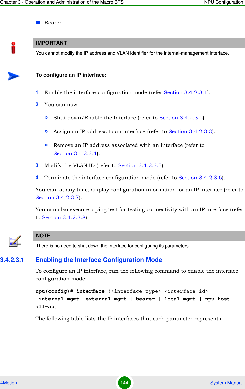
![Chapter 3 - Operation and Administration of the Macro BTS NPU Configuration4Motion 141 System ManualDo not specify the port number and type if you want to display configuration information for all physical interfaces. IMPORTANTAn error may occur if you specify an interface type or ID that does not exist.Command Syntaxnpu# show vlan port config [port <interface-type> <interface-id>]Privilege Level1Syntax Description Parameter Description Presence Default ValuePossible Values<interface-type> Indicates the type of physical interface for which VLAN membership information is to be displayed.Optional N/A fastethernetgigabitethernet<interface-id> Indicates the ID of the physical interface for which VLAN membership information is to be displayed.Optional N/A Fast Ethernet:0/8Gigabit Ethernet:0/90/10Display FormatVlan Port configuration table----------------------------------------Port <port number> Port Vlan ID : <value> Port Acceptable Frame Type : <value> Port Ingress Filtering : <Enabled/Disabled>](https://usermanual.wiki/Alvarion-Technologies/MICRO-25.Manual-p2/User-Guide-1329243-Page-41.png)
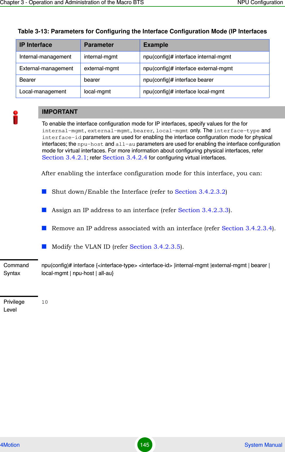
![Chapter 3 - Operation and Administration of the Macro BTS NPU Configuration4Motion 150 System Manual3.4.2.3.7 Displaying IP Interface Status and Configuration InformationTo display the status and configuration information for an IP interface, run the following command:npu# show ip interface [{internal-mgmt | external-mgmt | bearer | local-mgmt}]Do not specify the interface if you want to view configuration information for all IP interfaces.Command ModesInterface configuration modeIMPORTANTAn error may occur if the IP interface does not exist for the configured connectivity and boot mode.Command Syntaxnpu# show ip interface [{internal-mgmt | external-mgmt | bearer | local-mgmt}]Privilege Level1Syntax Description Parameter Description Presence Default ValuePossible Values{internal-mgmt | external-mgmt | bearer | local-mgmt}Indicates the interface for which configuration information is to be displayed.Do not specify any value for this parameter if you want to view configuration information for all IP interfaces.Optional N/A internal-mgmtexternal-mgmtbearerlocal-mgmtDisplay Format<Interface Name> is <up/down> Internet Address is <value>Broadcast Address <value>](https://usermanual.wiki/Alvarion-Technologies/MICRO-25.Manual-p2/User-Guide-1329243-Page-50.png)
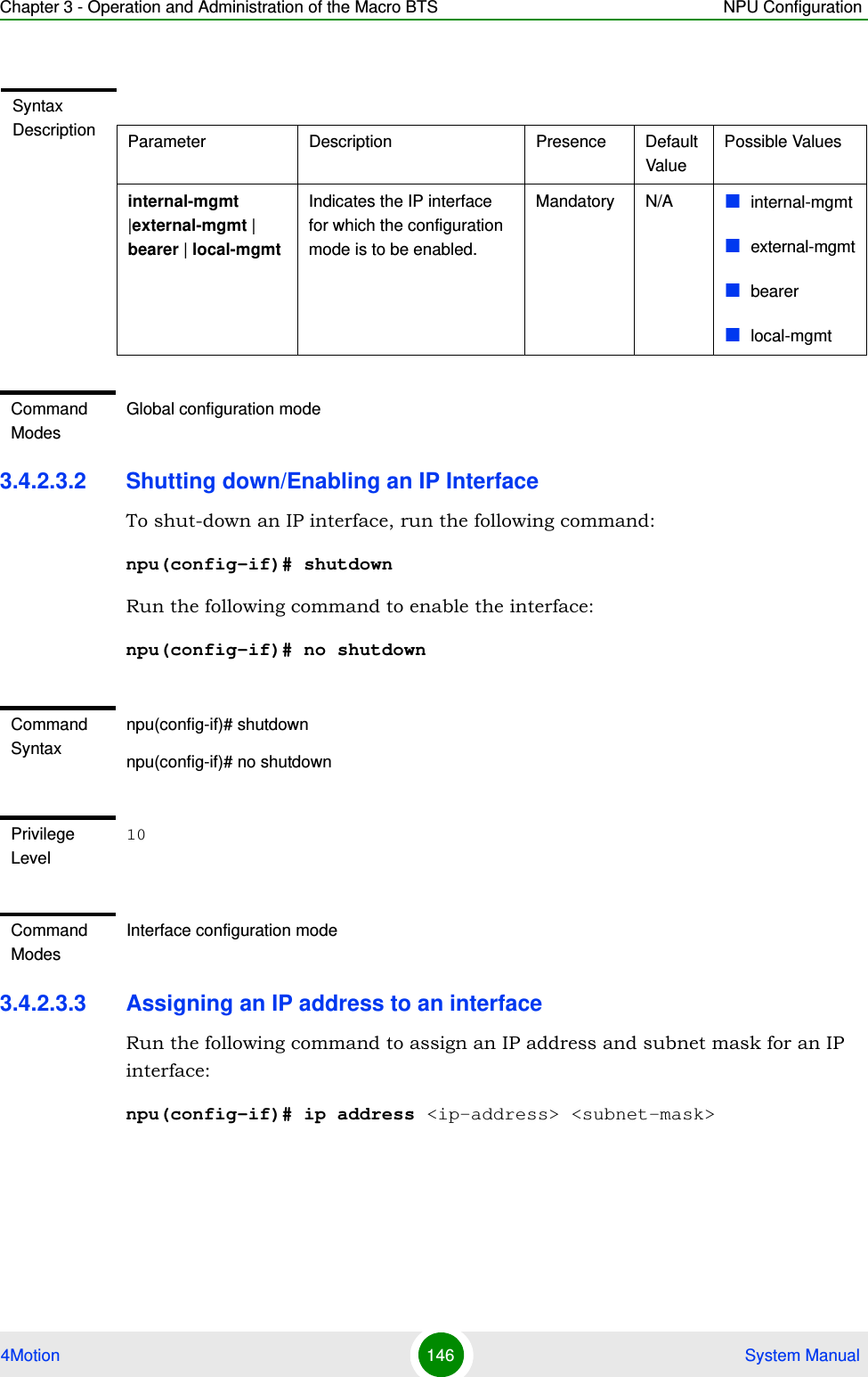
![Chapter 3 - Operation and Administration of the Macro BTS NPU Configuration4Motion 151 System Manual3.4.2.3.8 Testing Connectivity to an IP InterfaceTo test connectivity to an IP interface, perform a ping test using the following command:npu# ping <ip-address> [timeout <seconds(1-15)>] [count <count(1-20)>]Command ModesGlobal command modeIMPORTANTAn error may occur if the specified IP address does not match any of the available IP interfaces.Command Syntaxnpu# ping <ip-address> [timeout <seconds(1-15)>] [count <count(1-20)>]Privilege Level10Syntax Description Parameter Description Presence Default ValuePossible Values<ip-address> Indicates the interface for which a ping connectivity test should be performed.Mandatory N/A IP address of an host IP interfacetimeout <seconds(1-15)>The maximum time in seconds to wait for a response before sending another packet or terminating the testOptional 5 1-15count <count(1-20)> The number of packets to be sent.Optional 5 1-20Command ModesGlobal command mode](https://usermanual.wiki/Alvarion-Technologies/MICRO-25.Manual-p2/User-Guide-1329243-Page-51.png)
![Chapter 3 - Operation and Administration of the Macro BTS NPU Configuration4Motion 152 System Manual3.4.2.4 Configuring Virtual InterfacesIn addition to physical and IP interfaces, 4Motion defines the following virtual interfaces. All ACLs configured for filtering traffic destined towards the NPU or AUs, are attached to either of these interfaces.NPU-host: Used for configuring ACLs to filter traffic destined towards the NPU.All-AU: Used for configuring ACLs to filter traffic destined towards the AUs in the 4Motion shelf. For more information about attaching ACLs to the NPU or all-AUs, refer the section, “Attaching/De-attaching ACLs to/from an Interface” on page 223.3.4.2.5 Displaying Status and Configuration Information for Physical, IP, and Virtual InterfacesTo display the status and configuration information for physical, IP and/or virtual interfaces, run the following command:npu# show interfaces [{[<interface-type> <interface-id>] | internal-mgmt | external-mgmt | bearer | local-mgmt | npu-host | all-au}]To display the configuration information for all interfaces, do not specify a value for any parameter.The following table lists parameters to be specified with respect to the type of interface for which configuration information is to be displayed:Table 3-14: Parameters for Displaying Configuration Information for Physical, IP, and Virtual InterfacesInterface Parameters ExampleAll Interfaces None npu# show interfacesPhysical InterfacesFast Ethernet:<interface-type> <interface-id>npu# show interfaces fastethernet 0/8 Gigabit Ethernet<interface-type> <interface-id>npu# show interfaces gigabitethernet 0/9 npu# show interfaces gigabitethernet 0/10](https://usermanual.wiki/Alvarion-Technologies/MICRO-25.Manual-p2/User-Guide-1329243-Page-52.png)
![Chapter 3 - Operation and Administration of the Macro BTS NPU Configuration4Motion 153 System ManualIP Interfaces internal-mgmt npu# show interfaces internal-mgmt external-mgmt npu# show interfaces external-mgmt bearer npu# show interfaces bearer local-mgmt npu# show interfaces local-mgmt Virtual Interfacesnpu-host npu# show interfaces npu-hostall-au npu# show interfaces all-auIMPORTANTAn error may occur if:The interface type or ID that you have specified does not exist.The IP interface does not exist for the configured connectivity and boot mode.Command Syntaxnpu# show interfaces [{[<interface-type> <interface-id>] | internal-mgmt | external-mgmt | bearer | local-mgmt | npu-host | all-au}]Privilege Level1Syntax Description Parameter Description Presence Default ValuePossible Values[{[<interface-type> <interface-id>] | internal-mgmt | external-mgmt | bearer | local-mgmt | npu-host | all-au}]Indicates the type of interface (physical, IP, or virtual) for which configuration information is to be displayed. Do not specify any value for this parameter if you want to display configuration information for all physical, IP, and virtual interfaces.Optional N/A Refer to Table 3-14Table 3-14: Parameters for Displaying Configuration Information for Physical, IP, and Virtual InterfacesInterface Parameters Example](https://usermanual.wiki/Alvarion-Technologies/MICRO-25.Manual-p2/User-Guide-1329243-Page-53.png)
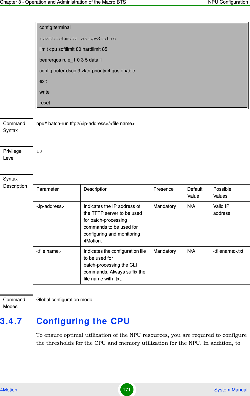
![Chapter 3 - Operation and Administration of the Macro BTS NPU Configuration4Motion 172 System Manualprotect the from hostile applications, the type and rate of traffic destined towards the NPU is limited by default. This section describes the commands to be executed for:“Configuring CPU and Memory Utilization Thresholds for the NPU” on page 172“Rate Limiting for the NPU” on page 1743.4.7.1 Configuring CPU and Memory Utilization Thresholds for the NPUThis section describes the commands for:“Specifying Thresholds for CPU and Memory Utilization for the NPU” on page 172“Displaying CPU and Memory Utilization Limits for the NPU” on page 1733.4.7.1.1 Specifying Thresholds for CPU and Memory Utilization for the NPUYou can use the CLI to configure the thresholds (soft and hard limits) for CPU and memory utilization for the NPU. When the soft or hard limit for either CPU or memory utilization is reached, an alarm is raised.To configure the thresholds (soft and hard limits) for CPU and memory utilization for the NPU, run the following command:npu(config)# limit {cpu | memory} ([softlimit <limit>] [hardlimit <limit>])For example, run the following command if you want to configure the soft and hard limits for CPU utilization to be 78 and 85 percent, respectively.npu(config)# limit cpu softlimit 80 hardlimit 85NOTETo display the current thresholds that are configured for CPU and memory utilization for the NPU, refer to Section 3.4.7.1.2.NOTEAn error may occur if the value of the softlimit parameter is higher than the hardlimit parameter.](https://usermanual.wiki/Alvarion-Technologies/MICRO-25.Manual-p2/User-Guide-1329243-Page-72.png)
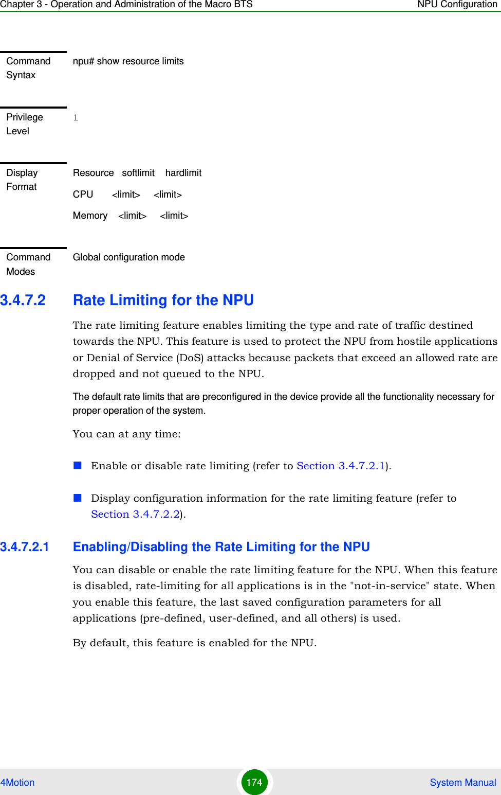
![Chapter 3 - Operation and Administration of the Macro BTS NPU Configuration4Motion 173 System Manual3.4.7.1.2 Displaying CPU and Memory Utilization Limits for the NPUTo display the configured CPU and memory utilization limits for the NPU, run the following command:npu# show resource limitsCommand Syntaxnpu(config)# limit {cpu | memory} ([softlimit <integer (1-99>] [hardlimit <integer (1-99>])Privilege Level10Syntax Description Parameter Description Presence Default ValuePossible Values{cpu | memory} Indicates whether the threshold is to be specified for CPU or memory utilization.Mandatory N/A cpu/ memory[softlimit <integer (1-99>]Indicates the soft limit, as a percentage, for CPU/memory utilization. When this limit is reached, the system raises a Minor or Major alarm.Optional 70 (for CPU and memory utilization)1-99[hardlimit <integer (1-99>])Indicates the hard limit, as a percentage, for CPU/memory utilization. When this limit is reached, the system raises a Critical alarm.The value of this parameter should always be greater than the softlimit parameter.Optional 90 (for CPU and memory utilization)1-99Command ModesGlobal configuration modeNOTETo configure the CPU and memory utilization limits for the NPU, refer to Section 3.4.7.1.2.](https://usermanual.wiki/Alvarion-Technologies/MICRO-25.Manual-p2/User-Guide-1329243-Page-73.png)
![Chapter 3 - Operation and Administration of the Macro BTS NPU Configuration4Motion 181 System Manualnpu(config-cmap)# set {[cos <new-cos(0-7)>] [ip dscp <new-dscp(0-63)>]}3.4.8.1.3 Deleting 802.1p and/or DSCP Values from a Class-mapRun the following command to delete the 802.1p VLAN priority and/or DSCP for this class-map.npu(config-cmap)# no {[cos <new-cos(0-7)>] [ip dscp <new-dscp(0-63)>]}Command Syntaxnpu(config-cmap)# set {[cos <new-cos(0-7)>] [ip dscp <new-dscp(0-63)>]}Privilege Level10Syntax Description Parameter Description Presence Default ValuePossible Values[cos <new-cos(0-7)>]Indicates the 802.1p VLAN priority value to be applied for this class-map.Optional N/A 0-7 where 0 is the lowest and 7 is the highest[ip dscp <new-dscp(0-63)>]Indicates the DSCP value to be applied for this class-map.Optional N/A 0-63Command ModesClass-map configuration modeIMPORTANTIf you are deleting the 802.1p VLAN priority and/or DSCP for a class-map that is associated with a QoS classification rule, first disable the QoS classification rules for that ACL. For details, refer to Section 3.4.8.3.IMPORTANTAn error may occur if the 802.1p or DSCP that you have specified do not exist for this class-map.Command Syntaxnpu(config-cmap)# no {[cos <new-cos(0-7)>] [ip dscp <new-dscp(0-63)>]}](https://usermanual.wiki/Alvarion-Technologies/MICRO-25.Manual-p2/User-Guide-1329243-Page-81.png)
![Chapter 3 - Operation and Administration of the Macro BTS NPU Configuration4Motion 182 System Manual3.4.8.1.4 Terminating the QoS Class-map Configuration ModeTo terminate the QoS class-map configuration mode, run the following command:npu(config-cmap)# exit3.4.8.1.5 Deleting a QoS Class-mapRun the following command to delete an existing QoS class-map:npu(config)# no class-map <class-map-number(1-65535)>Privilege Level10Syntax Description Parameter Description Presence Default ValuePossible Values[cos <new-cos(0-7)>]Indicates the 802.1p VLAN priority to be deleted for this class-map.Optional N/A 0-7[ip dscp <new-dscp(0-63)>]Indicates the DSCP to be deleted for this class-map.Optional N/A 0-63Command ModesQoS class-map configuration modeCommand Syntaxnpu(config-cmap)# exitPrivilege Level10Command ModesQoS class-map configuration modeIMPORTANTAn error may occur if you specify a class-map number that does not exist or is not within the range, 1-65535.](https://usermanual.wiki/Alvarion-Technologies/MICRO-25.Manual-p2/User-Guide-1329243-Page-82.png)
![Chapter 3 - Operation and Administration of the Macro BTS NPU Configuration4Motion 183 System Manual3.4.8.1.6 Displaying Configuration Information for a Class-mapRun the following command to view the configuration information for a class-map:npu# show class-map [<class-map-num(1-65535)>]Specify the class-map number if you want to view configuration information for a specific class-map. If you do not specify the class-map number, configuration information for all class-maps is displayed.Command Syntaxnpu(config)# no class-map <class-map-number(1-65535)>Privilege Level10Syntax Description Parameter Description Presence Default ValuePossible Values<class-map-number(1-65535)>Indicates the identifier of the QoS class-map number to be deleted.Mandatory N/A 1-65535Command ModesGlobal configuration modeIMPORTANTAn error may occur if you specify a class-map number that does not exist or is not within the range, 1-65535.Command Syntaxnpu# show class-map [<class-map-num(1-65535)>]Privilege Level1](https://usermanual.wiki/Alvarion-Technologies/MICRO-25.Manual-p2/User-Guide-1329243-Page-83.png)
![Chapter 3 - Operation and Administration of the Macro BTS NPU Configuration4Motion 184 System Manual3.4.8.2 Managing QoS Classification RulesQoS classification rules classify packets into flows, based on the following parameters:IP address of the host originating the traffic (the IP address assigned to the bearer, internal-management or external-management interface)Layer 3 protocol indicating either TCP or UDPLayer 4-source port for the application that needs to be marked (for example, FTP, Telnet, SNMP, MIP, or RADIUS)A class-map can be associated with each flow to define separate DSCP and/or VLAN priority bits for QoS handling of each flow. 1Enable the ACL configuration mode for ACL 199 (refer to Section 3.4.8.2.1).Syntax Description Parameter Description Presence Default ValuePossible Values[<class-map-num(1-65535)>]Indicates the identifier of the class-map for which configuration information is to be displayed. Do not specify a value for this parameter if you want to view the configuration information for all class-maps.Optional N/A 1-65535Display Format (for each class-map if requested for all class-maps)Class map <class map number>----------------------------------------------CoS Value : <value>DSCP Value : <value>Command ModesGlobal command modeTo configure a QoS classification rule:](https://usermanual.wiki/Alvarion-Technologies/MICRO-25.Manual-p2/User-Guide-1329243-Page-84.png)
![Chapter 3 - Operation and Administration of the Macro BTS NPU Configuration4Motion 185 System Manual2You can now:»Configure one or more QoS classification rules (refer to Section 3.4.8.2.2)»Delete one or more QoS classification rules (refer to Section 3.4.8.2.3)»Terminate the ACL configuration mode (refer to Section 3.4.8.2.4)You can, at any time, enable/disable QoS marking (refer to Section 3.4.8.3) or view the configuration information for ACL 199 (refer to Section 3.4.8.4).3.4.8.2.1 Enabling the ACL Configuration Mode for ACL 199To configure QoS classification rules for host-originating traffic, first enable the extended ACL 199 configuration mode.Run the following command to enable the extended ACL configuration mode for ACL 199. npu(config)# ip access-list {standard <access-list-number (1-99)> | extended <access-list-number (100-199)>} [name<string>]After you enable the ACL 199 configuration mode, you can configure one or several QoS classification rules, and associate them with the appropriate class-maps.IMPORTANTQoS classification rules can be associated only with ACL 199.IMPORTANTQoS classification rules can be added only to extended ACL 199Command Syntaxnpu(config)# ip access-list {standard <access-list-number (1-99)> | extended <access-list-number (100-199)>} [name <string>]Privilege Level10](https://usermanual.wiki/Alvarion-Technologies/MICRO-25.Manual-p2/User-Guide-1329243-Page-85.png)
![Chapter 3 - Operation and Administration of the Macro BTS NPU Configuration4Motion 186 System Manual3.4.8.2.2 Configuring a QoS Classification RuleYou can configure the QoS classification rules for the ACL with respect the following parameters:Source IP address for the host-originating application trafficApplication protocol (TCP or UDP)L4 source port of the application trafficQoS class-map identifier By default, there are 8 pre-configured QoS classification rules associated with the 8 pre-configured QoS class-maps:Syntax Description Parameter Description Presence Default ValuePossible Valuesextended <access-list-number (100-199)>Indicates the identifier of the extended ACL for which the ACL configuration mode is to be enabled. You must specify 199 to enable configuration of QoS classification rules.Mandatory N/A 199[name <string>] Indicates the name of the ACL for which the ACL configuration mode is to be enabled. Note: If you do not specify the ACL name, the ACL number is used as the default ACL name.Optional N/A String (upto 20 characters)Command ModesGlobal configuration modeTable 3-15: Pre-Configured QoS Classification Rules and Class-MapsIP Interface Type of Traffic Protocol Source Port Class Map DSCP 802.1p Bearer RADIUS UDP 1812 1 7 7](https://usermanual.wiki/Alvarion-Technologies/MICRO-25.Manual-p2/User-Guide-1329243-Page-86.png)
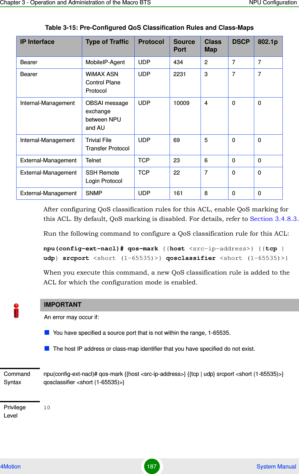
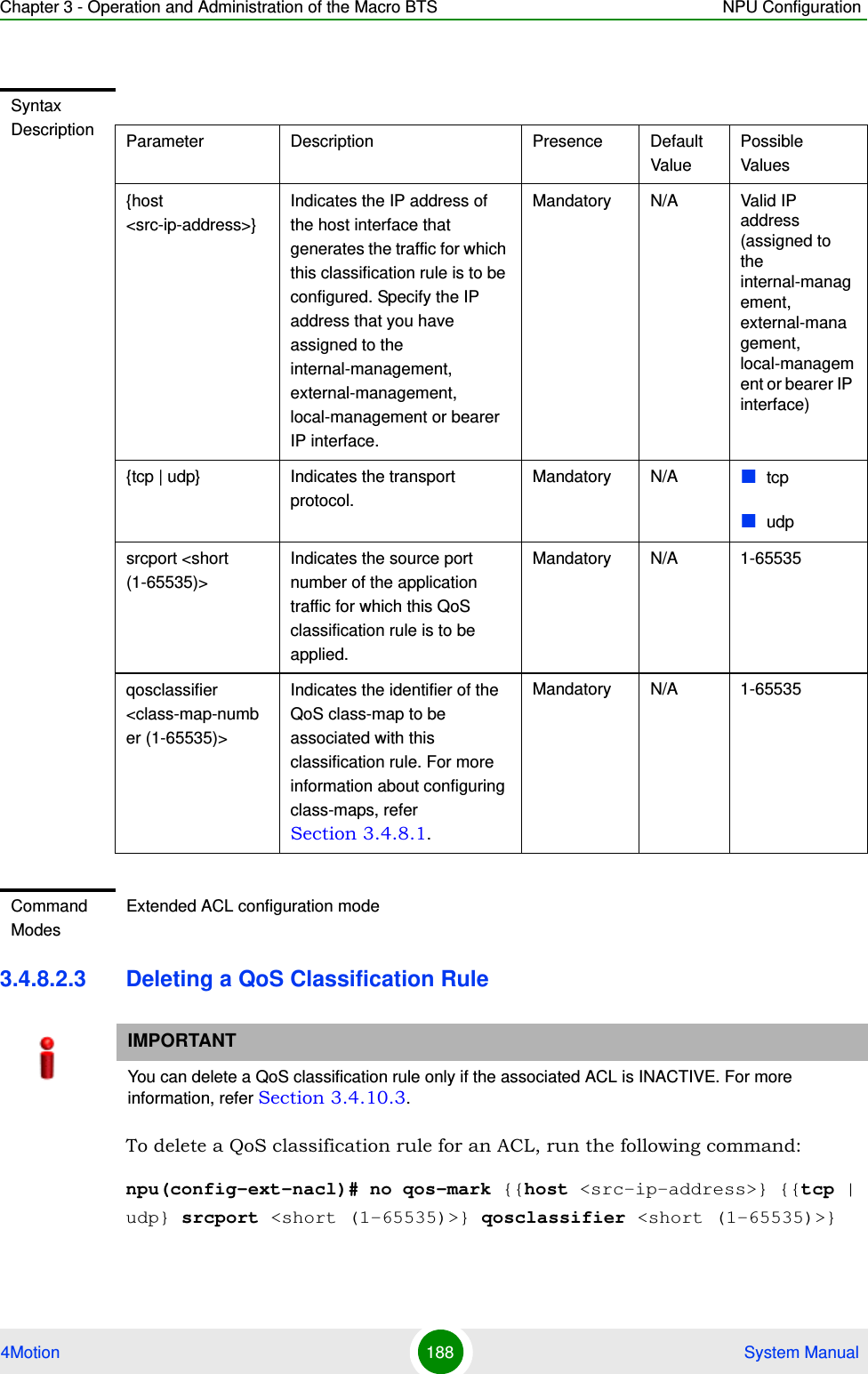
![Chapter 3 - Operation and Administration of the Macro BTS NPU Configuration4Motion 189 System ManualWhen you execute this command, the QoS classification rule is deleted from the ACL. IMPORTANTAn error may occur if you specify a combination of parameters that do not match any of the existing QoS classification rules.Command Syntaxnpu(config-ext-nacl)# no qos-mark {{host <src-ip-address>} {{tcp | udp} srcport <short (1-65535)>} qosclassifier <short (1-65535)>}Privilege Level10Syntax Description Parameter Description Presence Default ValuePossible Values[host <src-ip-address>]Indicates the IP address of the host interface that generates the traffic for which this classification rule is to be deleted.Mandatory N/A Valid IP address (assigned to the internal-management, external-management or bearer IP interface){tcp | udp} Indicates the transport protocol.Mandatory N/A tcpudpsrcport <short (1-65535)>Indicates the source port number of the application traffic for which this QoS classification rule is to be deleted.Mandatory N/A 1-65535qosclassifier <class-map-number (1-65535)>Indicates the identifier of the QoS class-map associated with the classification rule to be deleted. For more information about class-maps, refer Section 3.4.8.1.Mandatory N/A 1-65535](https://usermanual.wiki/Alvarion-Technologies/MICRO-25.Manual-p2/User-Guide-1329243-Page-89.png)
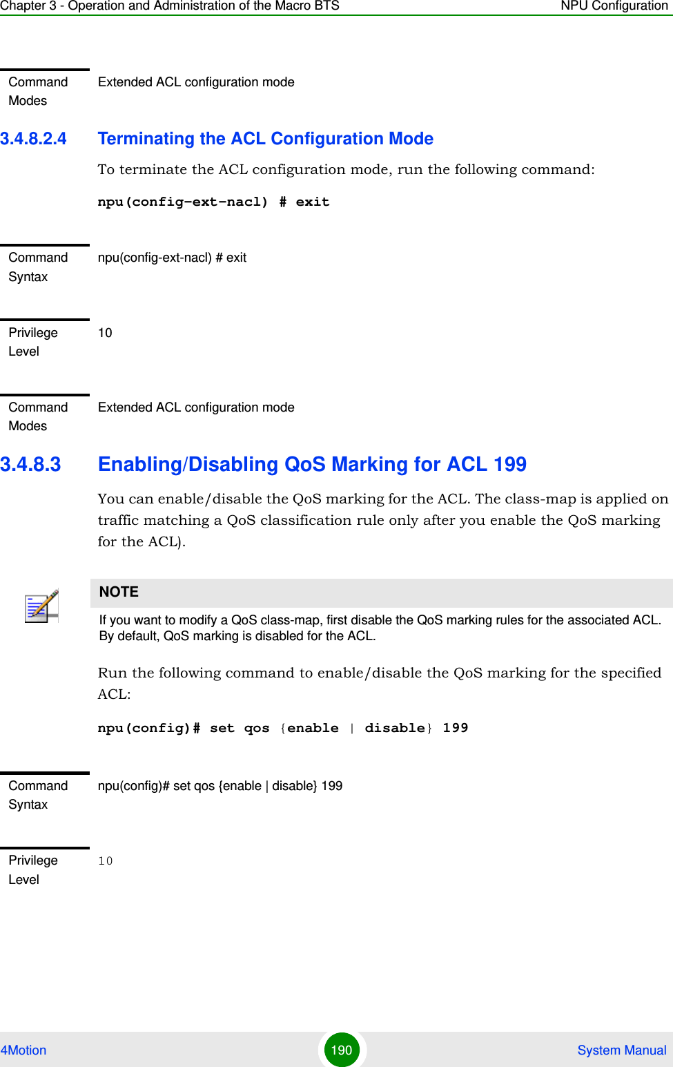
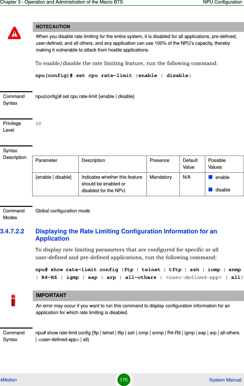
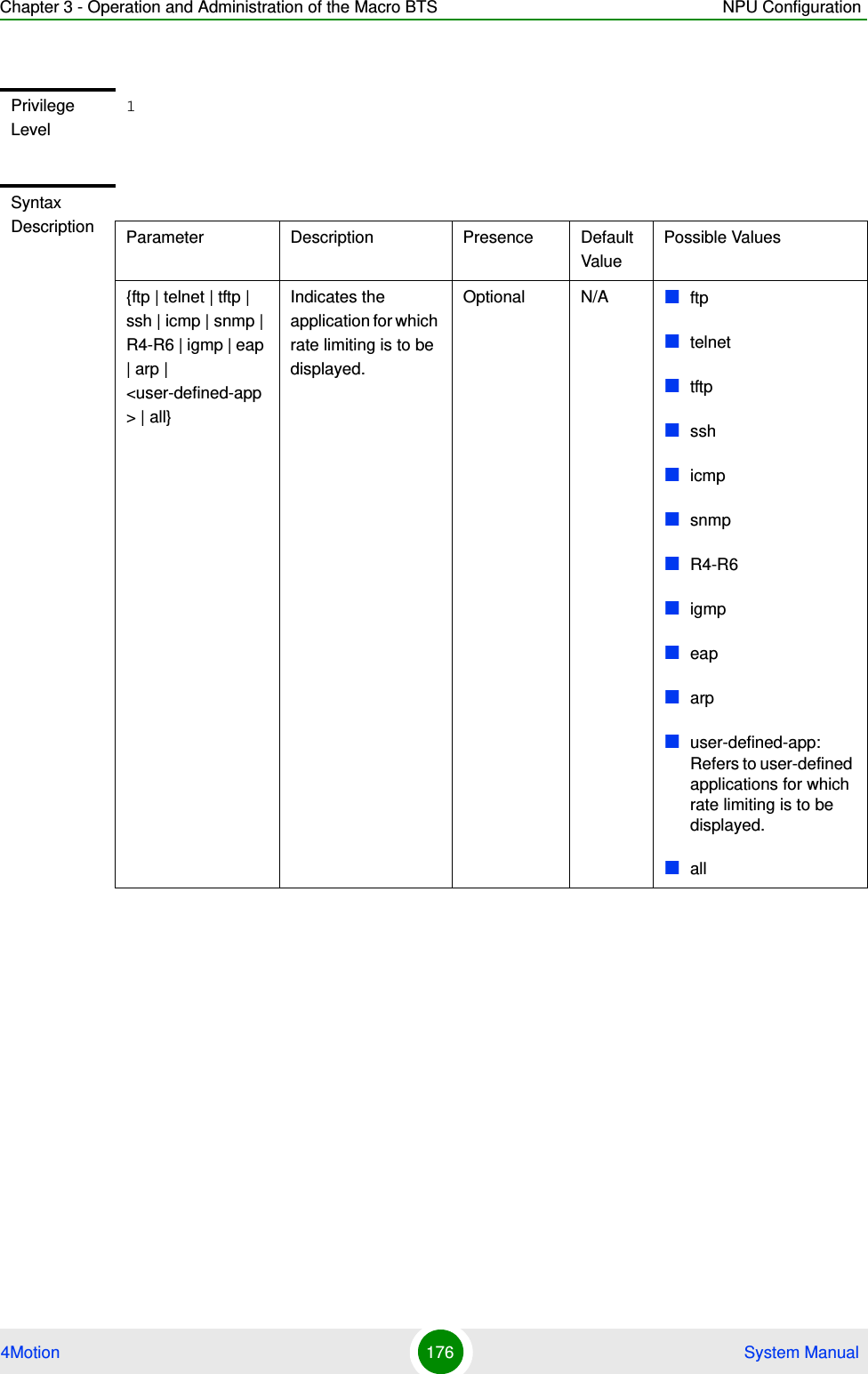
![Chapter 3 - Operation and Administration of the Macro BTS NPU Configuration4Motion 191 System Manual3.4.8.4 Displaying ACL 199 Configuration InformationRun the following command to display the configuration information for ACL 199:npu# show access-lists [{199 | <access-list-199-name}]Syntax Description Parameter Description Presence Default ValuePossible Values{enable | disable} Indicates whether QoS marking should be enabled or disabled for a specific ACL.Mandatory disable enabledisable199 Indicates the identifier of the ACL for which the QoS marking is to be activated. You must specify 199.Mandatory N/A 199Command ModesGlobal configuration modeIMPORTANTAn error may occur if the ACL name you have specified does not exist.Command Syntaxnpu# show access-lists [199| <access-list-199-name}]Privilege Level1Syntax Description Parameter Description Presence Default ValuePossible Values[199 | <access-list-199-name}]To view configuration information for ACL 199, specify 199 or the name configured for this ACL.Mandatory for viewing information for ACL 199.N/A 199String; the name configured for ACL 199.](https://usermanual.wiki/Alvarion-Technologies/MICRO-25.Manual-p2/User-Guide-1329243-Page-91.png)
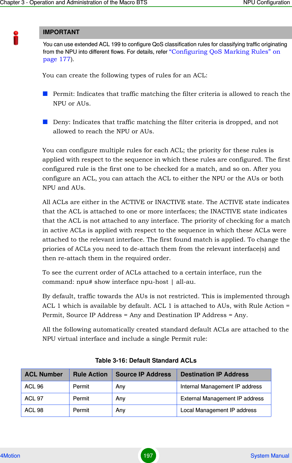
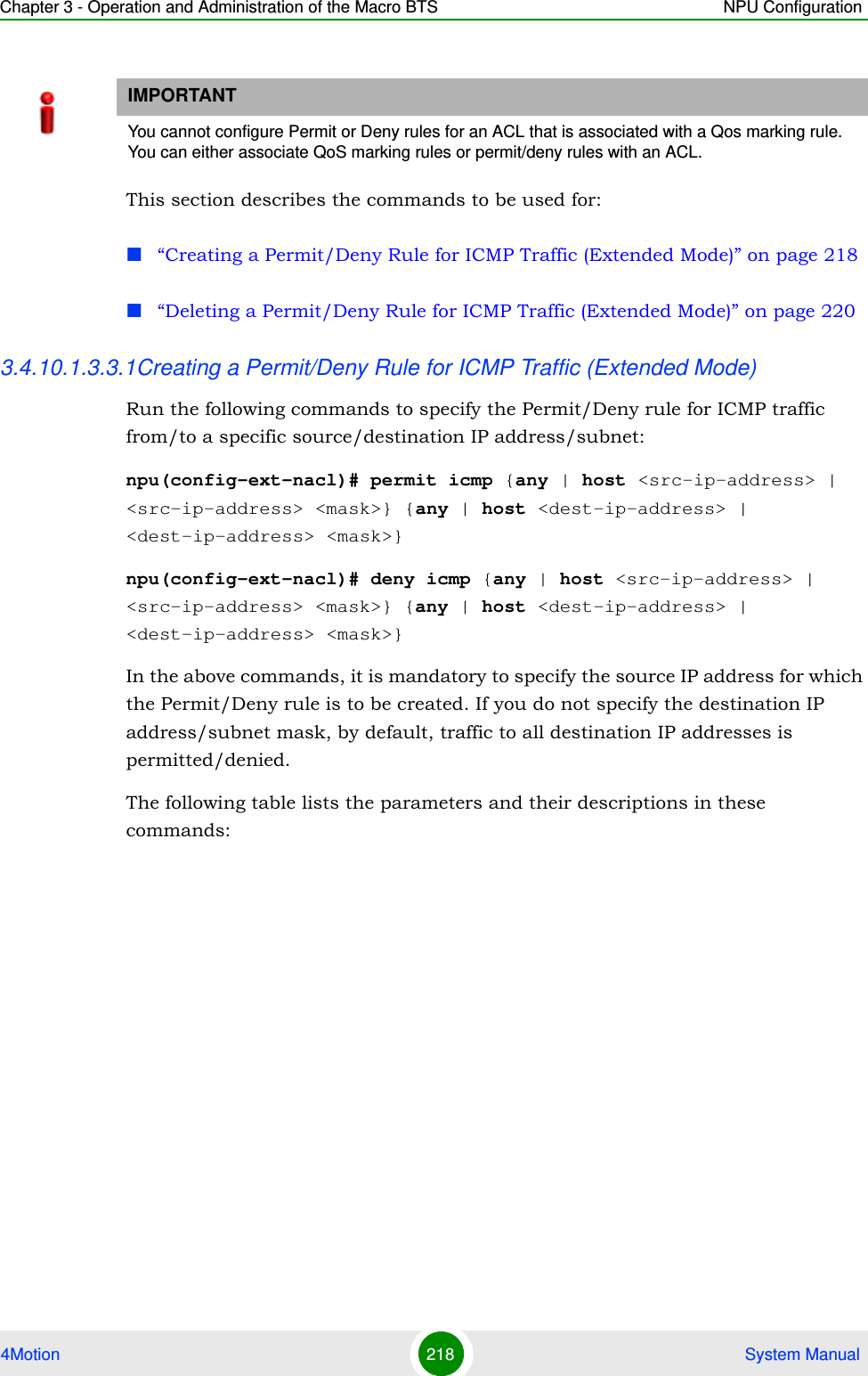
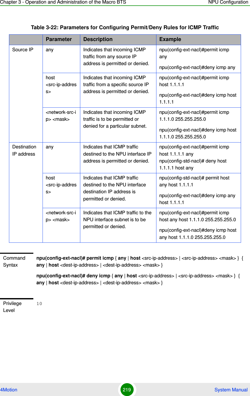
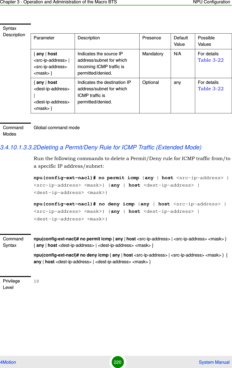
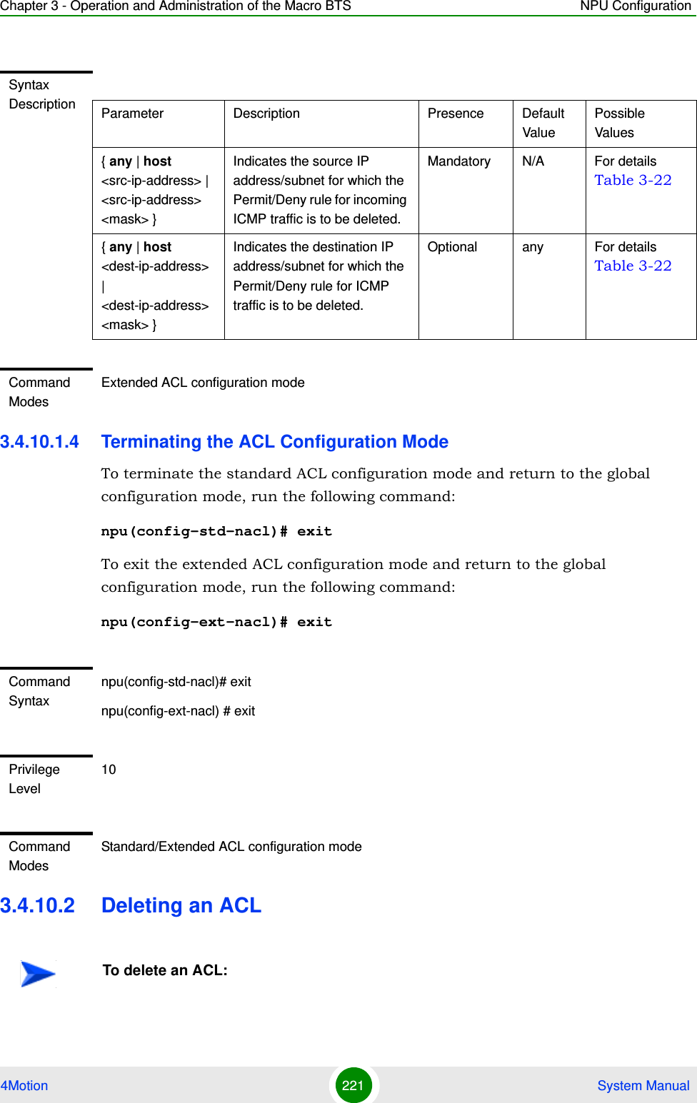
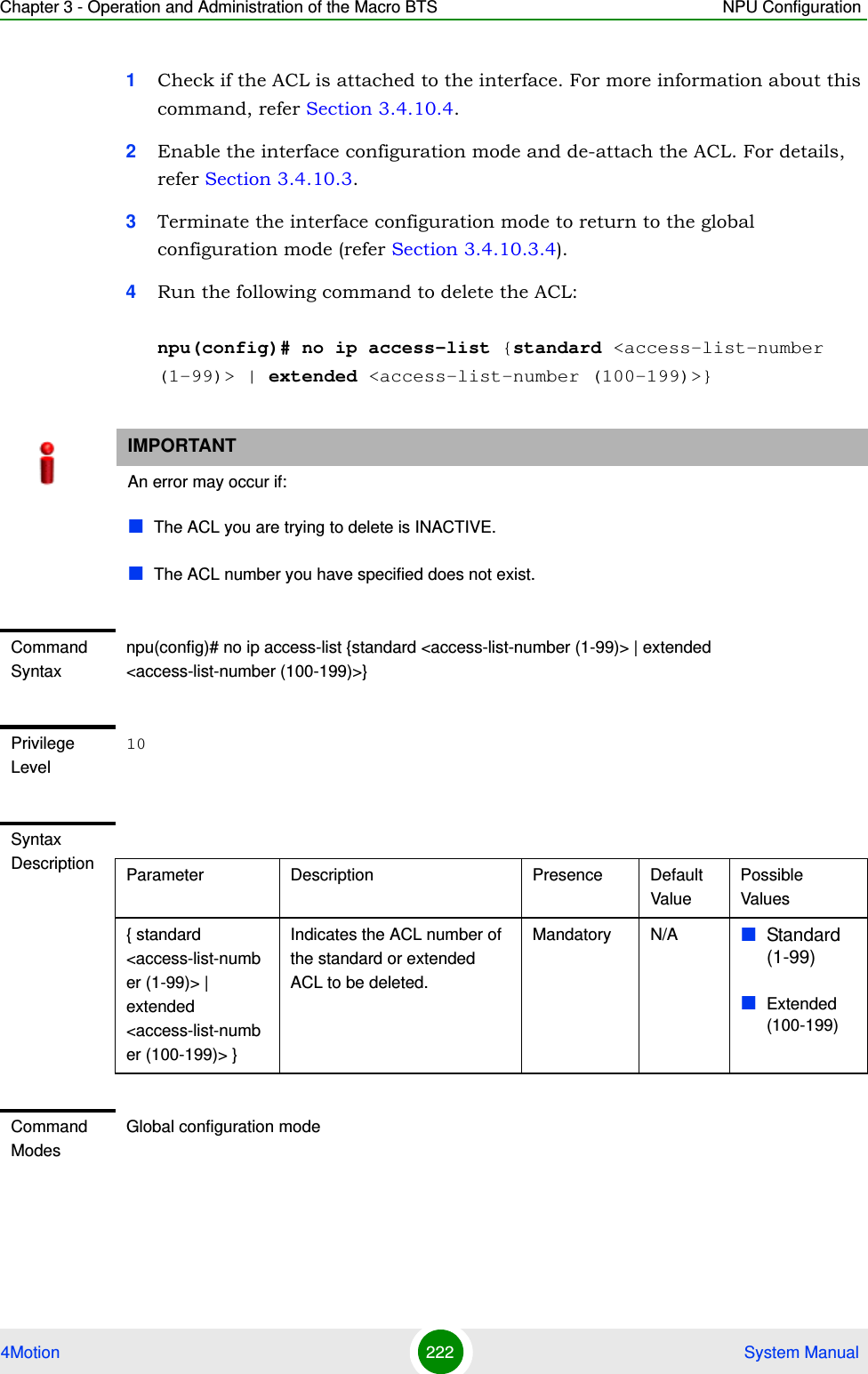
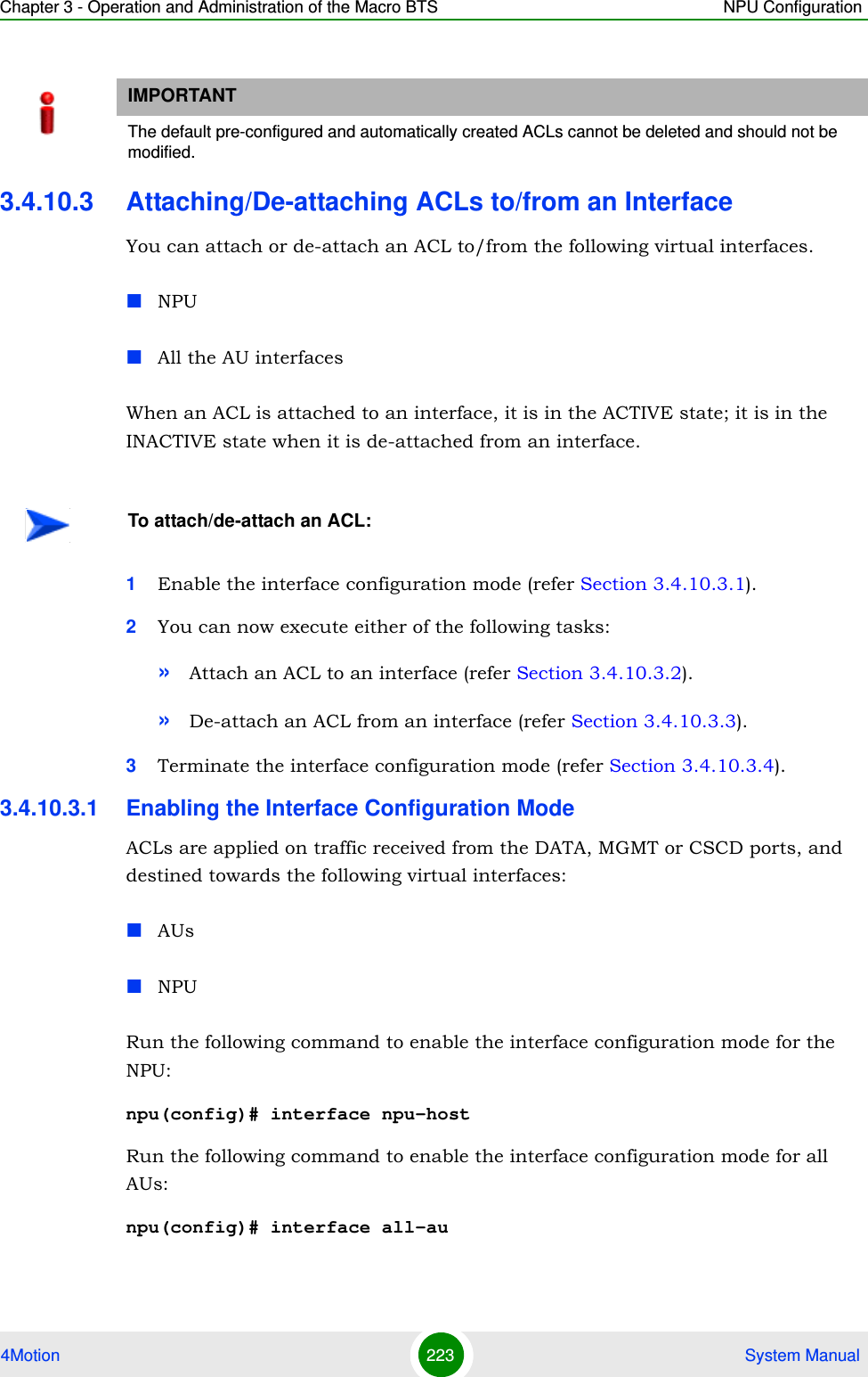
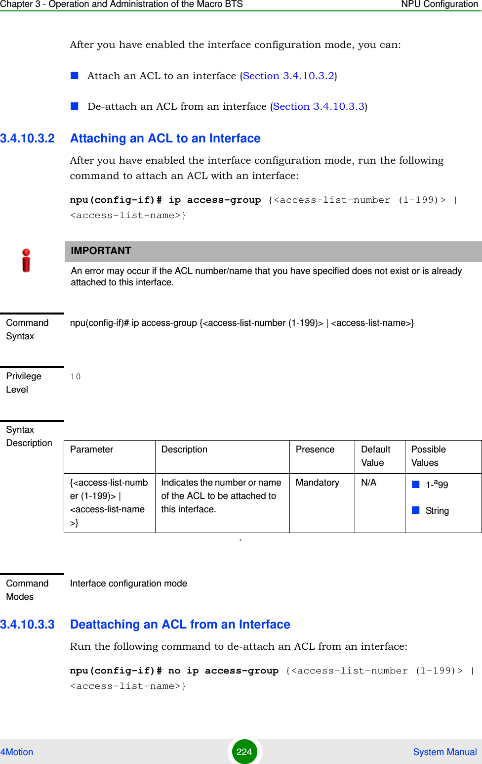
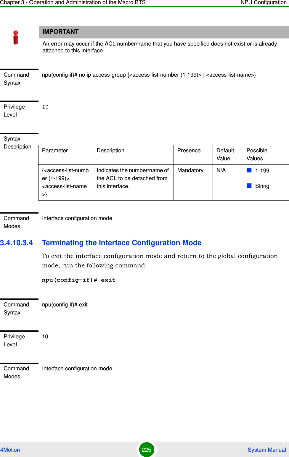
![Chapter 3 - Operation and Administration of the Macro BTS NPU Configuration4Motion 200 System Manual3.4.10.1.1 Enable the ACL Configuration Mode/Creating an ACLTo configure an ACL, first enable either of the following ACL configuration modes: StandardExtendedTo apply this ACL to traffic destined towards the AUs or the NPU, you are required to activate this ACL (for details refer Section 3.4.10.3). Run the following command to enable the ACL configuration mode. You can also use this command to create a new ACL.npu(config)# ip access-list {standard <access-list-number (1-99)> | extended <access-list-number (100-199)>}[name<string>]When you run this command, the ACL configuration mode for the newly-created ACL is automatically enabled. If the name is not specified when creating a new ACL, the default name will be the specified ACL number.For example, run the following command to create ACL 22 in the standard mode:npu(config)# ip access-list standard 22Standard ACL 22 will be created with the default name 22.For example, run the following command to create ACL 111 in the extended mode, with the name ACL-111:npu(config)# ip access-list extended 111 ACL-111After you create an ACL or enable the ACL configuration mode, you canConfigure the ACL in the standard mode (refer Section 3.4.10.1.2)Configuring the ACL in the extended mode (refer Section 3.4.10.1.3)IMPORTANTACL 199 is the default extended ACL that is pre-configured in the system, and is not attached to any interface, that is, it is INACTIVE. However, ACL 199 is reserved for QoS classification rules. You cannot configure Permit/Deny rules for ACL 199.To view the default configuration information for ACL 199, you can run the following command:npu# show access-lists 199For details on using ACL 199 refer to Section 3.4.8.](https://usermanual.wiki/Alvarion-Technologies/MICRO-25.Manual-p2/User-Guide-1329243-Page-100.png)
![Chapter 3 - Operation and Administration of the Macro BTS NPU Configuration4Motion 201 System ManualIMPORTANTAn error may occur if:·You specify an invalid ACL number. The ACL number should be between 1 and 99 in the standard mode, and between 100 and 199 in the extended mode.The ACL name you have specified is already used for another ACL or is more than 20 characters.Command Syntaxnpu(config)# ip access-list {standard <access-list-number (1-99)> | extended <access-list-number (100-199)>}[name<string>]Privilege Level10Syntax Description Parameter Description Presence Default ValuePossible Valuesstandard <access-list-number (1-99)> | extended <access-list-number (100-199)>Denotes the number of the standard or extended ACL that is to be created for which the ACL configuration mode is to be enabled. If you are creating a new ACL, the ACL configuration mode is automatically enabled when you execute this command.Note: ACL 199 is reserved for QoS classification rules and cannot be used for creating Permit/Deny rules.Mandatory N/A standard 1-99extended (100-198)[name<string>] Indicates the name of the ACL to be created for which the ACL configuration mode is to be enabled. Optional ACL nameString (upto 20 characters)Command ModesGlobal configuration mode](https://usermanual.wiki/Alvarion-Technologies/MICRO-25.Manual-p2/User-Guide-1329243-Page-101.png)
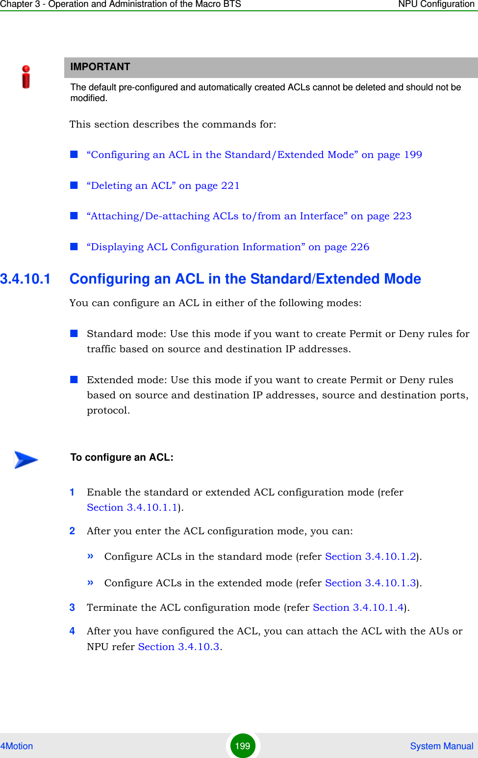
![Chapter 3 - Operation and Administration of the Macro BTS NPU Configuration4Motion 202 System Manual3.4.10.1.2 Configuring ACLs in the Standard ModeAfter you have enabled the standard ACL configuration mode, you can create or delete the Permit/Deny rules for forwarding traffic from/to a particular source/destination IP address.This section describes the commands for:“Creating a Permit/Deny Rule (Standard Mode)” on page 202“Deleting a Permit/Deny Rule (Standard Mode)” on page 2043.4.10.1.2.1 Creating a Permit/Deny Rule (Standard Mode)Run the following commands to create the Permit/Deny rules for forwarding traffic from/to a particular source/destination IP address:npu(config-std-nacl)# permit {any | host <src-ip-address> | <network-src-ip> <mask>} [{any | host <dest-ip-address> | <network-dest-ip> <mask>}]npu(config-std-nacl)# deny {any | host <src-ip-address> | <network-src-ip> <mask>} [{any | host <dest-ip-address> | <network-dest-ip> <mask>}] The following table lists the parameters and their descriptions in these commands.IMPORTANTYou cannot create Permit or Deny rules for an ACL that is associated with a Qos marking rule. You can either associate QoS marking rules or permit/deny rules with an ACL.IMPORTANTAfter you have configured the rules to be applied on an ACL, you can attach the ACL to the NPU or AUs. The ACL enables filtering of traffic destined to these interfaces. For more information, refer to Section 3.4.10.3.IMPORTANTIn the above commands, it is mandatory to specify the source IP address for which the Permit/Deny rule is to be created. If you do not specify the destination IP address/subnet mask, by default, traffic to all destination IP addresses configured for the NPU is permitted/denied.](https://usermanual.wiki/Alvarion-Technologies/MICRO-25.Manual-p2/User-Guide-1329243-Page-102.png)
![Chapter 3 - Operation and Administration of the Macro BTS NPU Configuration4Motion 203 System ManualTable 3-19: Parameters for Configuring Permit/Deny Rules in the Standard ACL ModeParameter Description ExampleSource IP any Indicates that incoming traffic from any source IP address is permitted or denied.npu(config-std-nacl)# permit anynpu(config-std-nacl)# deny anyhost <src-ip-address>Indicates that incoming traffic from a specific source IP address is permitted or denied. npu(config-std-nacl)# permit host 1.1.1.1npu(config-std-nacl)# deny host 1.1.1.1<network-src-ip> <mask>Indicates that incoming traffic is to be permitted or denied for a particular subnet.npu(config-std-nacl)# permit 1.1.1.0 255.255.255.0npu(config-std-nacl)# deny 1.1.1.0 255.255.255.0Destination IP addressany Indicates that traffic destined to all NPU IP addresses is permitted or denied.npu(config-std-nacl)# permit host 1.1.1.1 anynpu(config-std-nacl)# deny host 1.1.1.1 anyhost <src-ip-address>Indicates that traffic destined to a specific destination IP address is permitted or denied. npu(config-std-nacl)# permit any host 1.1.1.1npu(config-std-nacl)# deny any host 1.1.1.1<network-src-ip> <mask>Indicates that traffic destined to a particular subnet is to be permitted or denied.npu(config-std-nacl)# permit any 1.1.1.0 255.255.255.0npu(config-std-nacl)# deny any 1.1.1.0 255.255.255.0Command Syntaxnpu(config-std-nacl)# permit {any | host <src-ip-address> | <network-src-ip> <mask>} [{any | host <dest-ip-address> | <network-dest-ip> <mask>}]npu(config-std-nacl)# deny { any | host <src-ip-address> | <network-src-ip> <mask> } [ { any | host <dest-ip-address> | <network-dest-ip> <mask> } ] Syntax Description Parameter Description Presence Default ValuePossible Values{ any | host <src-ip-address> | <network-src-ip> <mask> }Indicates the source IP address/subnet for which incoming traffic is permitted/denied.Mandatory N/A For details, refer Table 3-19](https://usermanual.wiki/Alvarion-Technologies/MICRO-25.Manual-p2/User-Guide-1329243-Page-103.png)
![Chapter 3 - Operation and Administration of the Macro BTS NPU Configuration4Motion 204 System Manual3.4.10.1.2.2 Deleting a Permit/Deny Rule (Standard Mode)Run the following commands to delete the Permit/Deny rule for incoming traffic from/to a specific IP address/subnet.npu(config-std-nacl)# no permit {any | host <src-ip-address> | <network-src-ip> <mask>} [{any | host <dest-ip-address> | <network-dest-ip> <mask>}]npu(config-std-nacl)# no deny {any | host <src-ip-address> | <network-src-ip> <mask>} [{any | host <dest-ip-address> | <network-dest-ip> <mask>}] [ { any | host <dest-ip-address> | <network-dest-ip> <mask> } ]Indicates the destination IP address/subnet for which traffic is permitted/denied Optional any For details, refer Table 3-19Command ModesStandard ACL configuration modeCommand Syntaxnpu(config-std-nacl)# no permit { any | host <src-ip-address> | <network-src-ip> <mask> } [ { any | host <dest-ip-address> | <network-dest-ip> <mask> } ]npu(config-std-nacl)# no deny { any | host <src-ip-address> | <network-src-ip> <mask> } [ { any | host <dest-ip-address> | <network-dest-ip> <mask> } ] Privilege Level10Syntax Description Parameter Description Presence Default ValuePossible Values{ any | host <src-ip-address> | <network-src-ip> <mask> }Indicates the source IP address/subnet for which the Permit/Deny rule is to be deleted.Mandatory N/A For details, refer Table 3-19 [ { any | host <dest-ip-address> | <network-dest-ip> <mask> } ]Indicates the destination IP address/subnet for which the Permit/Deny rule is to be deleted.Optional any For details, refer Table 3-19](https://usermanual.wiki/Alvarion-Technologies/MICRO-25.Manual-p2/User-Guide-1329243-Page-104.png)
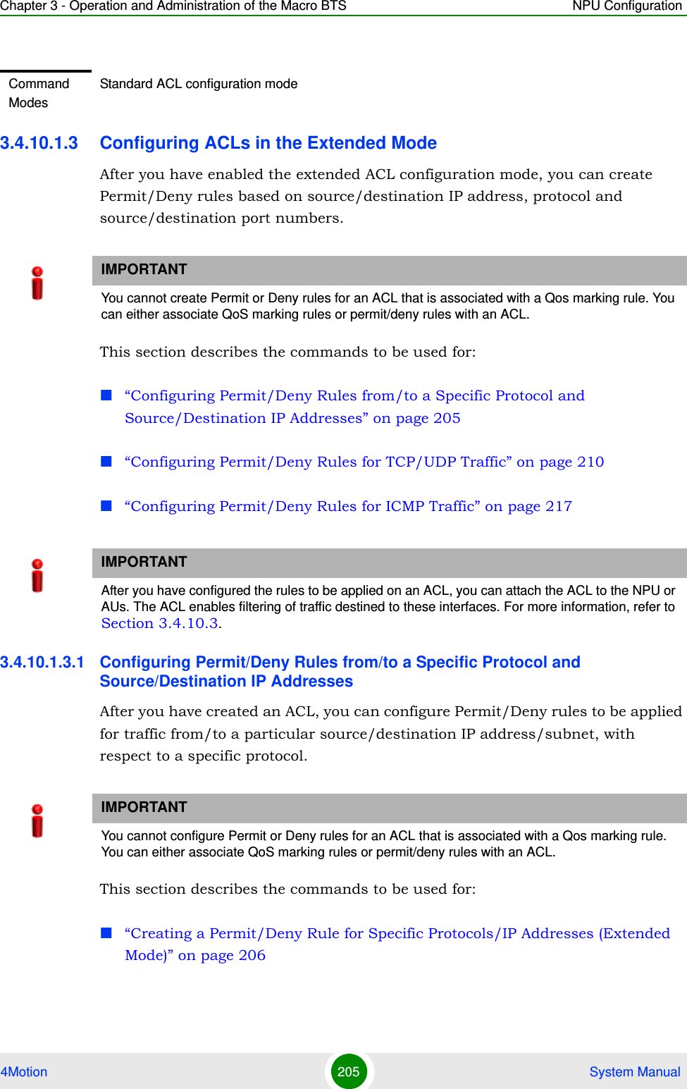
![Chapter 3 - Operation and Administration of the Macro BTS NPU Configuration4Motion 210 System Manual3.4.10.1.3.2 Configuring Permit/Deny Rules for TCP/UDP TrafficAfter you have created an ACL, you can configure Permit/Deny rules for TCP and UDP traffic from/to specific source and destination IP address and port. This section describes the commands to be used for:“Creating a Permit/Deny Rule for TCP/UDP Traffic (Extended Mode)” on page 210“Deleting a Permit/Deny Rule for TCP/UDP Traffic (Extended Mode)” on page 2153.4.10.1.3.2.1Creating a Permit/Deny Rule for TCP/UDP Traffic (Extended Mode)Run the following commands to specify the Permit rule for TCP/UDP traffic from/to a specific source/destination IP address/port:npu(config-ext-nacl)# permit tcp {any | host <src-ip-address> | <src-ip-address> <src-mask>} [{gt <port-number (1-65535)> | lt <port-number (1-65535)> |eq <port-number (1-65535)> | range <port-number (1-65535)> <port-number (1-65535)>}] {any | host <dest-ip-address> | <dest-ip-address> <dest-mask>} {gt <port-number (1-65535)> | lt <port-number (1-65535)> | eq <port-number (1-65535)> | range <port-number (1-65535)> <port-number (1-65535)>}]npu(config-ext-nacl)# permit udp {any | host <src-ip-address> | <src-ip-address> <src-mask>} [{gt <port-number (1-65535)> | lt <port-number (1-65535)> |eq <port-number (1-65535)> | range <port-number (1-65535)> <port-number (1-65535)>}] {any | host { any | host <dest-ip-addresq> | <dest-ip-address> <mask> }Indicates the destination IP address/subnet for which the Permit/Deny rule is to be deleted.Optional any For details, refer Table 3-20Command ModesExtended ACL configuration modeIMPORTANTYou cannot configure Permit or Deny rules for an ACL that is associated with a Qos marking rule. You can either associate QoS marking rules or permit/deny rules with an ACL.](https://usermanual.wiki/Alvarion-Technologies/MICRO-25.Manual-p2/User-Guide-1329243-Page-110.png)
![Chapter 3 - Operation and Administration of the Macro BTS NPU Configuration4Motion 211 System Manual<dest-ip-address> | <dest-ip-address> <dest-mask>} {gt <port-number (1-65535)> | lt <port-number (1-65535)> | eq <port-number (1-65535)> | range <port-number (1-65535)> <port-number (1-65535)>}]Run the following commands to specify the Deny rule for TCP/UDP traffic from/to a specific source/destination IP address/port:npu(config-ext-nacl)# deny tcp {any | host <src-ip-address> | <src-ip-address> <src-mask>} [{gt <port-number (1-65535)> | lt <port-number (1-65535)> |eq <port-number (1-65535)> | range <port-number (1-65535)> <port-number (1-65535)>}] {any | host <dest-ip-address> | <dest-ip-address> <dest-mask>} {gt <port-number (1-65535)> | lt <port-number (1-65535)> | eq <port-number (1-65535)> | range <port-number (1-65535)> <port-number (1-65535)>}]npu(config-ext-nacl)# deny udp {any | host <src-ip-address> | <src-ip-address> <src-mask>} [{gt <port-number (1-65535)> | lt <port-number (1-65535)> |eq <port-number (1-65535)> | range <port-number (1-65535)> <port-number (1-65535)>}] {any | host <dest-ip-address> | <dest-ip-address> <dest-mask>} {gt <port-number (1-65535)> | lt <port-number (1-65535)> | eq <port-number (1-65535)> | range <port-number (1-65535)> <port-number (1-65535)>}]In the above commands, it is mandatory to specify the source and destination IP address for which the Permit/Deny rule is to be created.The following table lists the parameters and their descriptions in these commands:IMPORTANTTo increase the granularity of the Permit/Deny rule you are creating, specify the source and destination port numbers for the source and destination IP addresses.](https://usermanual.wiki/Alvarion-Technologies/MICRO-25.Manual-p2/User-Guide-1329243-Page-111.png)
![Chapter 3 - Operation and Administration of the Macro BTS NPU Configuration4Motion 212 System ManualTable 3-21: Parameters for Configuring Permit/Deny Rules for TCP/UDP TrafficParameter Description ExampleSource IP addressany Indicates that incoming TCP/UDP traffic from any source IP address is permitted or denied.npu(config-ext-nacl)# permit tcp any anynpu(config-ext-nacl)# deny udp any host <src-ip-address>Indicates that incoming TCP/UDP traffic from a specific source IP address is permitted or denied.npu(config-ext-nacl)# permit tcp host 1.1.1.1 anynpu(config-ext-nacl)# deny udp host 1.1.1.1 <network-src-ip> <mask>Indicates that incoming TCP/UDP traffic is to be permitted or denied for a particular subnet.npu(config-ext-nacl)# permit tcp 1.1.1.0 255.255.255.0 anynpu(config-ext-nacl)# deny udp 1.1.1.0 255.255.255.0 Source port [{gt <port-number (1-65535)> Indicates that incoming TCP/ UDP traffic is to be permitted or denied from the source port for which the port number is greater than the value of this parameter.npu(config-ext-nacl)# permit tcp 1.1.1.0 255.255.255.0 gt 1111npu(config-ext-nacl)# deny udp host 1.1.1.1 gt 1010 [{lt <port-number (1-65535)> Indicates that incoming TCP/ UDP traffic is to be permitted or denied from the source port for which the port number is less than the value of this parameter.npu(config-ext-nacl)# permit tcp 1.1.1.0 255.255.255.0 lt 1111npu(config-ext-nacl)# deny udp host 1.1.1.1 lt 1010[{eq <port-number (1-65535)> Indicates that incoming TCP/ UDP traffic is to be permitted or denied from the source port for which the port number is equal to the value of this parameter.npu(config-ext-nacl)# permit tcp 1.1.1.0 255.255.255.0 eq 8080npu(config-ext-nacl)# deny udp host 1.1.1.1 eq 4040range <port-number (1-65535)> <port-number (1-65535)>}]Indicates that incoming TCP/ UDP traffic is to be permitted or denied from the source port for which the port number is within the range specified by this parameter.npu(config-ext-nacl)# permit tcp 1.1.1.0 255.255.255.0 range 1010 8080npu(config-ext-nacl)# deny udp host 1.1.1.1 range 1010 4040](https://usermanual.wiki/Alvarion-Technologies/MICRO-25.Manual-p2/User-Guide-1329243-Page-112.png)
![Chapter 3 - Operation and Administration of the Macro BTS NPU Configuration4Motion 213 System ManualDestination IP addressany Indicates that TCP/UDP traffic to all NPU interface IP addresses is permitted or denied.npu(config-ext-nacl)# permit tcp 1.1.1.1 host any npu(config-ext-nacl)# deny udp any anyhost <src-ip-address>Indicates that TCP/UDP traffic to a specific NPU interface IP address is permitted or denied. npu(config-ext-nacl)# permit tcp any host 1.1.1.1 host host 1.1.1.1npu(config-ext-nacl)# deny udp any host 1.1.1.1<network-src-ip> <mask>Indicates that TCP/UDP traffic is to be permitted or denied for a particular NPU interface subnet.npu(config-ext-nacl)# permit tcp any host 1.1.1.0 255.255.255.0npu(config-ext-nacl)# deny udp any host 1.1.1.0 255.255.255.0Destination port[{gt <port-number (1-65535)> Indicates that TCP/ UDPtraffic is to be permitted or denied to the NPU interface source port for which the port number is greater than the value of this parameter.npu(config-ext-nacl)# permit tcp host 1.1.1.1 host any gt 8080npu(config-ext-nacl)# deny udp any any[{lt <port-number (1-65535)> Indicates that TCP/ UDP traffic is to be permitted or denied to the NPU interface source port for which the port number is less than the value of this parameter.npu(config-ext-nacl)# permit tcp host 1.1.1.0 255.255.255.0 any lt 1111npu(config-ext-nacl)# deny udp any host 1.1.1.1 lt 1010[{eq <port-number (1-65535)> Indicates that TCP/ UDP traffic is to be permitted or denied to the NPU interface source port for which the port number is equal to the value of this parameter.npu(config-ext-nacl)# permit tcp any 1.1.1.0 255.255.255.0 eq 8080npu(config-ext-nacl)# deny udp any host 1.1.1.1 eq 4040range <port-number (1-65535)> <port-number (1-65535)>}]Indicates that TCP/ UDP traffic is to be permitted or denied the NPU interface source port for which the port number is within the range specified by this parameter.npu(config-ext-nacl)# permit tcp host 1.1.1.1 host 1.1.1.0 255.255.255.0 range 1010 8080npu(config-ext-nacl)# deny udp host 1.1.1.1 any range 1010 4040Table 3-21: Parameters for Configuring Permit/Deny Rules for TCP/UDP TrafficParameter Description Example](https://usermanual.wiki/Alvarion-Technologies/MICRO-25.Manual-p2/User-Guide-1329243-Page-113.png)
![Chapter 3 - Operation and Administration of the Macro BTS NPU Configuration4Motion 214 System ManualCommand Syntaxnpu(config-ext-nacl)# deny tcp {any | host <src-ip-address> | <src-ip-address> <src-mask> } [{gt <port-number (1-65535)> | lt <port-number (1-65535)> |eq <port-number (1-65535)> | range <port-number (1-65535)> <port-number (1-65535)>}] {any | host <dest-ip-address> | <dest-ip-address> <dest-mask>} {gt <port-number (1-65535)> | lt <port-number (1-65535)> | eq <port-number (1-65535)> | range <port-number (1-65535)> <port-number (1-65535)>}]npu(config-ext-nacl)# deny udp {any | host <src-ip-address> | <src-ip-address> <src-mask> } [{gt <port-number (1-65535)> | lt <port-number (1-65535)> |eq <port-number (1-65535)> | range <port-number (1-65535)> <port-number (1-65535)>}] {any | host <dest-ip-address> | <dest-ip-address> <dest-mask>} {gt <port-number (1-65535)> | lt <port-number (1-65535)> | eq <port-number (1-65535)> | range <port-number (1-65535)> <port-number (1-65535)>}]Privilege Level10Syntax Description Parameter Description Presence Default ValuePossible Valuesany | host <src-ip-address> | <src-ip-address> <src-mask>Indicates the source host for which incoming TCP/UDP traffic is permitted/denied.Mandatory N/A For details, refer Table 3-21[{gt <port-number (1-65535)> | lt <port-number (1-65535)> |eq <port-number (1-65535)> | range <port-number (1-65535)> <port-number (1-65535)>}]Indicates the source port from which incoming TCP/UDP traffic is permitted/denied.Optional 0-65535 For details, refer Table 3-21any | host <dest-ip-address> | <dest-ip-address> <dest-mask>Indicates the destination IP address/subnet for which TCP/UDP traffic is permitted/denied.Mandatory N/A For details, refer Table 3-21](https://usermanual.wiki/Alvarion-Technologies/MICRO-25.Manual-p2/User-Guide-1329243-Page-114.png)
![Chapter 3 - Operation and Administration of the Macro BTS NPU Configuration4Motion 215 System Manual3.4.10.1.3.2.2Deleting a Permit/Deny Rule for TCP/UDP Traffic (Extended Mode)Run the following commands to delete a Permit rule for TCP/UDP traffic from/to a specific IP address/port:npu(config-ext-nacl)# no permit tcp {any | host <src-ip-address> | <src-ip-address> <src-mask>} [{gt <port-number (1-65535)> | lt <port-number (1-65535)> |eq <port-number (1-65535)> | range <port-number (1-65535)> <port-number (1-65535)>}] {any | host <dest-ip-address> | <dest-ip-address> <dest-mask>} {gt <port-number (1-65535)> | lt <port-number (1-65535)> | eq <port-number (1-65535)> | range <port-number (1-65535)> <port-number (1-65535)>}]npu(config-ext-nacl)# no permit udp {any | host <src-ip-address> | <src-ip-address> <src-mask>} [{gt <port-number (1-65535)> | lt <port-number (1-65535)> |eq <port-number (1-65535)> | range <port-number (1-65535)> <port-number (1-65535)>}] {any | host <dest-ip-address> | <dest-ip-address> <dest-mask>} {gt <port-number (1-65535)> | lt <port-number (1-65535)> | eq <port-number (1-65535)> | range <port-number (1-65535)> <port-number (1-65535)>}]Run the following commands to delete a Deny rule for TCP/UDP traffic from/to a specific IP address/port:npu(config-ext-nacl)# no deny tcp {any | host <src-ip-address> | <src-ip-address> <src-mask>} [{gt <port-number (1-65535)> | lt <port-number (1-65535)> |eq <port-number (1-65535)> | range <port-number (1-65535)> <port-number (1-65535)>}] {any | host <dest-ip-address> | <dest-ip-address> <dest-mask>} {gt <port-number {gt <port-number (1-65535)> | lt <port-number (1-65535)> | eq <port-number (1-65535)> | range <port-number (1-65535)> <port-number (1-65535)>}]Indicates the destination port to which TCP/UDP traffic is permitted/denied.Optional 0-65535 For details, refer Table 3-21Command ModesExtended ACL configuration mode](https://usermanual.wiki/Alvarion-Technologies/MICRO-25.Manual-p2/User-Guide-1329243-Page-115.png)
![Chapter 3 - Operation and Administration of the Macro BTS NPU Configuration4Motion 216 System Manual(1-65535)> | lt <port-number (1-65535)> | eq <port-number (1-65535)> | range <port-number (1-65535)> <port-number (1-65535)>}]npu(config-ext-nacl)# no deny udp {any | host <src-ip-address> | <src-ip-address> <src-mask>} [{gt <port-number (1-65535)> | lt <port-number (1-65535)> |eq <port-number (1-65535)> | range <port-number (1-65535)> <port-number (1-65535)>}] {any | host <dest-ip-address> | <dest-ip-address> <dest-mask>} {gt <port-number (1-65535)> | lt <port-number (1-65535)> | eq <port-number (1-65535)> | range <port-number (1-65535)> <port-number (1-65535)>}]Command Syntax (for Permit Rule)npu(config-ext-nacl)# no permit tcp {any | host <src-ip-address> | <src-ip-address> <src-mask> } [{gt <port-number (1-65535)> | lt <port-number (1-65535)> |eq <port-number (1-65535)> | range <port-number (1-65535)> <port-number (1-65535)>}] {any | host <dest-ip-address> | <dest-ip-address> <dest-mask>} {gt <port-number (1-65535)> | lt <port-number (1-65535)> | eq <port-number (1-65535)> | range <port-number (1-65535)> <port-number (1-65535)>}]npu(config-ext-nacl)# no permit udp {any | host <src-ip-address> | <src-ip-address> <src-mask> } [{gt <port-number (1-65535)> | lt <port-number (1-65535)> |eq <port-number (1-65535)> | range <port-number (1-65535)> <port-number (1-65535)>}] {any | host <dest-ip-address> | <dest-ip-address> <dest-mask>} {gt <port-number (1-65535)> | lt <port-number (1-65535)> | eq <port-number (1-65535)> | range <port-number (1-65535)> <port-number (1-65535)>}]Command Syntax (for Deny Rule)npu(config-ext-nacl)# no deny tcp {any | host <src-ip-address> | <src-ip-address> <src-mask> } [{gt <port-number (1-65535)> | lt <port-number (1-65535)> |eq <port-number (1-65535)> | range <port-number (1-65535)> <port-number (1-65535)>}] {any | host <dest-ip-address> | <dest-ip-address> <dest-mask>} {gt <port-number (1-65535)> | lt <port-number (1-65535)> | eq <port-number (1-65535)> | range <port-number (1-65535)> <deny-number (1-65535)>}]npu(config-ext-nacl)# no deny udp {any | host <src-ip-address> | <src-ip-address> <src-mask> } [{gt <port-number (1-65535)> | lt <port-number (1-65535)> |eq <port-number (1-65535)> | range <port-number (1-65535)> <port-number (1-65535)>}] {any | host <dest-ip-address> | <dest-ip-address> <dest-mask>} {gt <port-number (1-65535)> | lt <port-number (1-65535)> | eq <port-number (1-65535)> | range <port-number (1-65535)> <port-number (1-65535)>}]Privilege Level10](https://usermanual.wiki/Alvarion-Technologies/MICRO-25.Manual-p2/User-Guide-1329243-Page-116.png)
![Chapter 3 - Operation and Administration of the Macro BTS NPU Configuration4Motion 217 System Manual3.4.10.1.3.3 Configuring Permit/Deny Rules for ICMP TrafficAfter you have created an ACL, you can configure Permit/Deny rules for ICMP traffic from/to specific a source and destination IP address/subnet. Syntax Description Parameter Description Presence Default ValuePossible Valuesany | host <src-ip-address> | <src-ip-address> <src-mask>Indicates the source host for which the Permit/Deny rule for incoming TCP/UDP traffic is to be deleted.Mandatory N/A For details, refer Table 3-21[{gt <port-number (1-65535)> | lt <port-number (1-65535)> |eq <port-number (1-65535)> | range <port-number (1-65535)> <port-number (1-65535)>}]Indicates the source port for which the Permit/Deny rule for incoming TCP/UDP traffic is to be deleted.Optional 1-65535 For details, refer Table 3-21any | host <dest-ip-address> | <dest-ip-address> <dest-mask>Indicates the NPU IP address/subnet for which the Permit/Deny rule for TCP/UDP traffic is to be deleted.Mandatory N/A For details, refer Table 3-21[{gt <port-number (1-65535)> | lt <port-number (1-65535)> |eq <port-number (1-65535)> | range <port-number (1-65535)> <port-number (1-65535)>}]Indicates the NPU interface port for which the Permit/Deny rule for incoming TCP/UDP traffic is to be deleted.Optional 1-65535 For details, refer Table 3-21Command ModesExtended ACL configuration mode](https://usermanual.wiki/Alvarion-Technologies/MICRO-25.Manual-p2/User-Guide-1329243-Page-117.png)
![Chapter 3 - Operation and Administration of the Macro BTS NPU Configuration4Motion 226 System Manual3.4.10.4 Displaying ACL Configuration InformationRun the following command to display the configuration information for a specific ACL:npu# show access-lists [{<access-list-number (1-199)> | <access-list-name}]IMPORTANTAn error may occur if the ACL number/name you have specified does not exist.Command Syntaxnpu# show access-lists [{<access-list-number (1-199)> | <access-list-name}]Privilege Level1Syntax Description Parameter Description Presence Default ValuePossible Values[{<access-list-number (1-199)> | <access-list-name}]Indicates the number or name of the ACL for which configuration information is to be displayed. If you do not provide the ACL number or name, configuration information is displayed for all ACLs.Optional N/A 1-199String](https://usermanual.wiki/Alvarion-Technologies/MICRO-25.Manual-p2/User-Guide-1329243-Page-126.png)
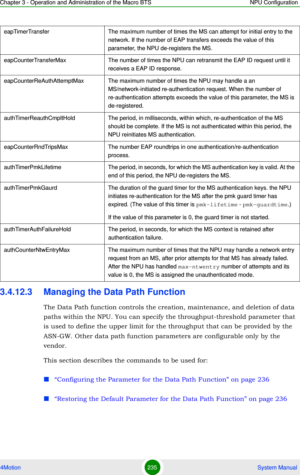
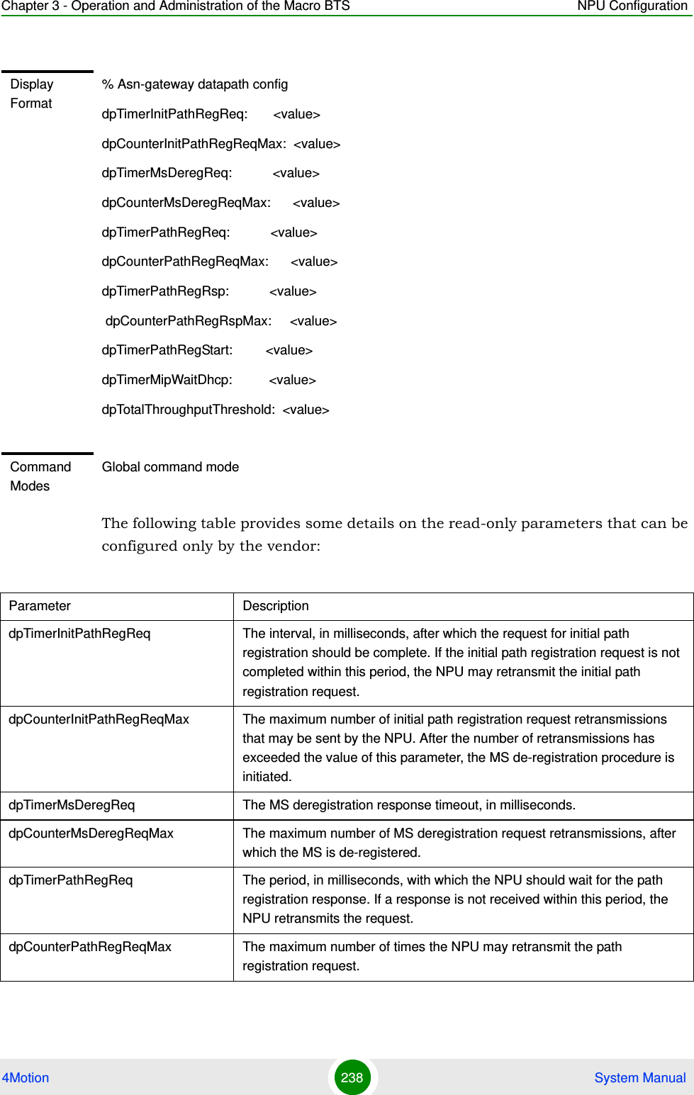
![Chapter 3 - Operation and Administration of the Macro BTS NPU Configuration4Motion 236 System Manual“Displaying Configuration Information for the Data Path Function” on page 2373.4.12.3.1 Configuring the Parameter for the Data Path FunctionTo configure the parameter for the data path function, run the following command:npu(config)# datapath throughput-threshold <integer(1-500)>3.4.12.3.2 Restoring the Default Parameter for the Data Path FunctionTo restore the default configuration for the data path function, run the following command:npu(config)# no datapath [throughput-threshold]IMPORTANTAn error may occur if you provide an invalid value for the throughput-threshold parameter. Refer to the syntax description for more information about the appropriate values configuring this parameter.The throughput-threshold parameter must be specified (the value is optional): The command npu(config)# datapath will return an Incomplete Command error.Command Syntaxnpu(config)# datapath throughput-threshold <integer(1-500)>Privilege Level10Syntax Description Parameter Description Presence Default ValuePossible Valuesthroughput-threshold <integer(1-500)>Maximal total throughput in Mbps via ASN-GW (UL+DL). Used as threshold for "no resource" reject and relevant alarm Optional 200 1-500Command ModesGlobal configuration mode](https://usermanual.wiki/Alvarion-Technologies/MICRO-25.Manual-p2/User-Guide-1329243-Page-136.png)
![Chapter 3 - Operation and Administration of the Macro BTS NPU Configuration4Motion 237 System Manual3.4.12.3.3 Displaying Configuration Information for the Data Path FunctionTo display configuration information for the Data Path function, run the following command:npu# show datapathNOTERefer to Section 3.4.12.3.1 for a description and default value of this parameter. Command Syntaxnpu(config)# no datapath [throughput-threshold]Privilege Level15Command ModesGlobal configuration modeCommand Syntaxnpu# show datapathPrivilege Level1](https://usermanual.wiki/Alvarion-Technologies/MICRO-25.Manual-p2/User-Guide-1329243-Page-137.png)
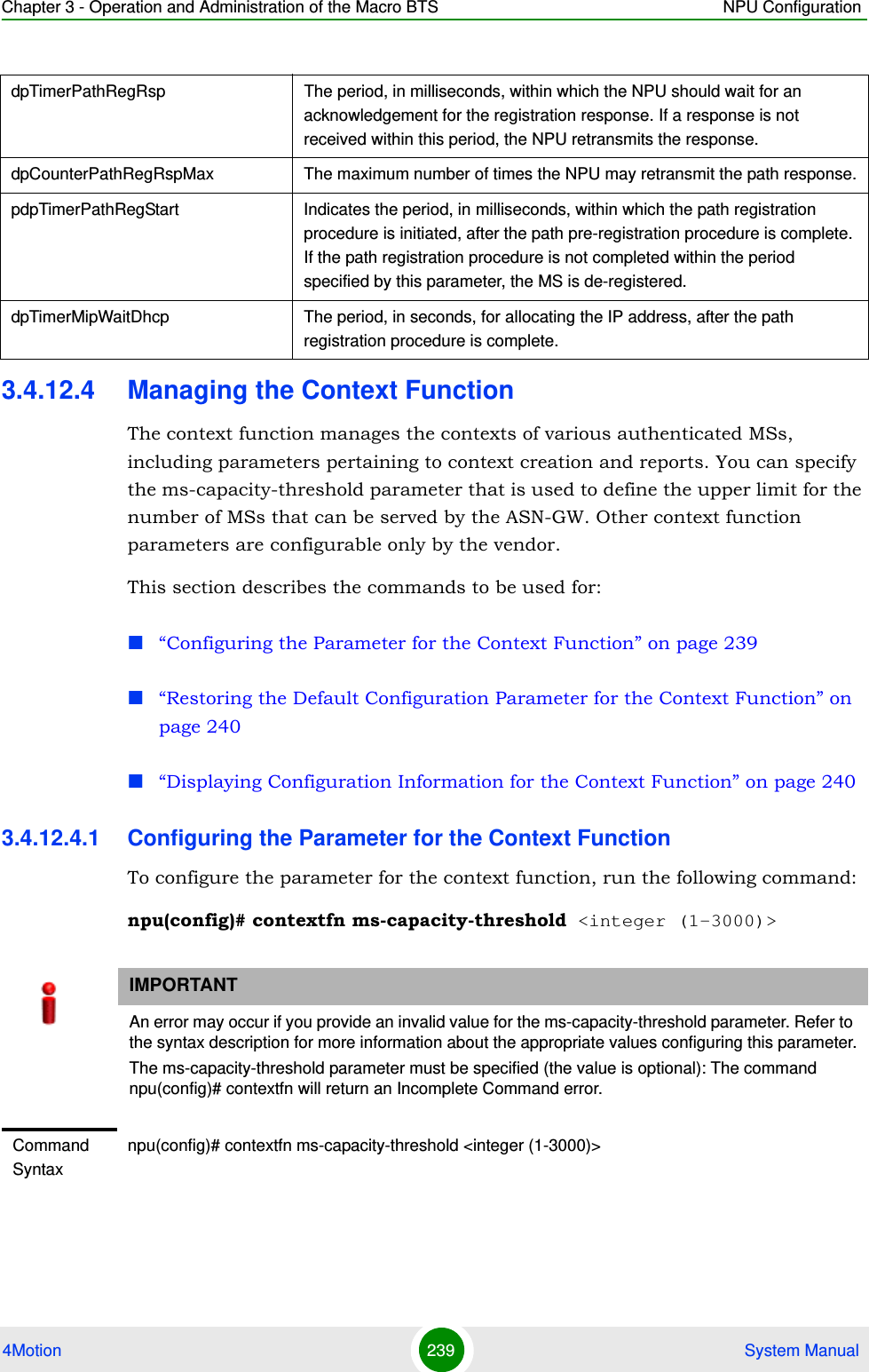
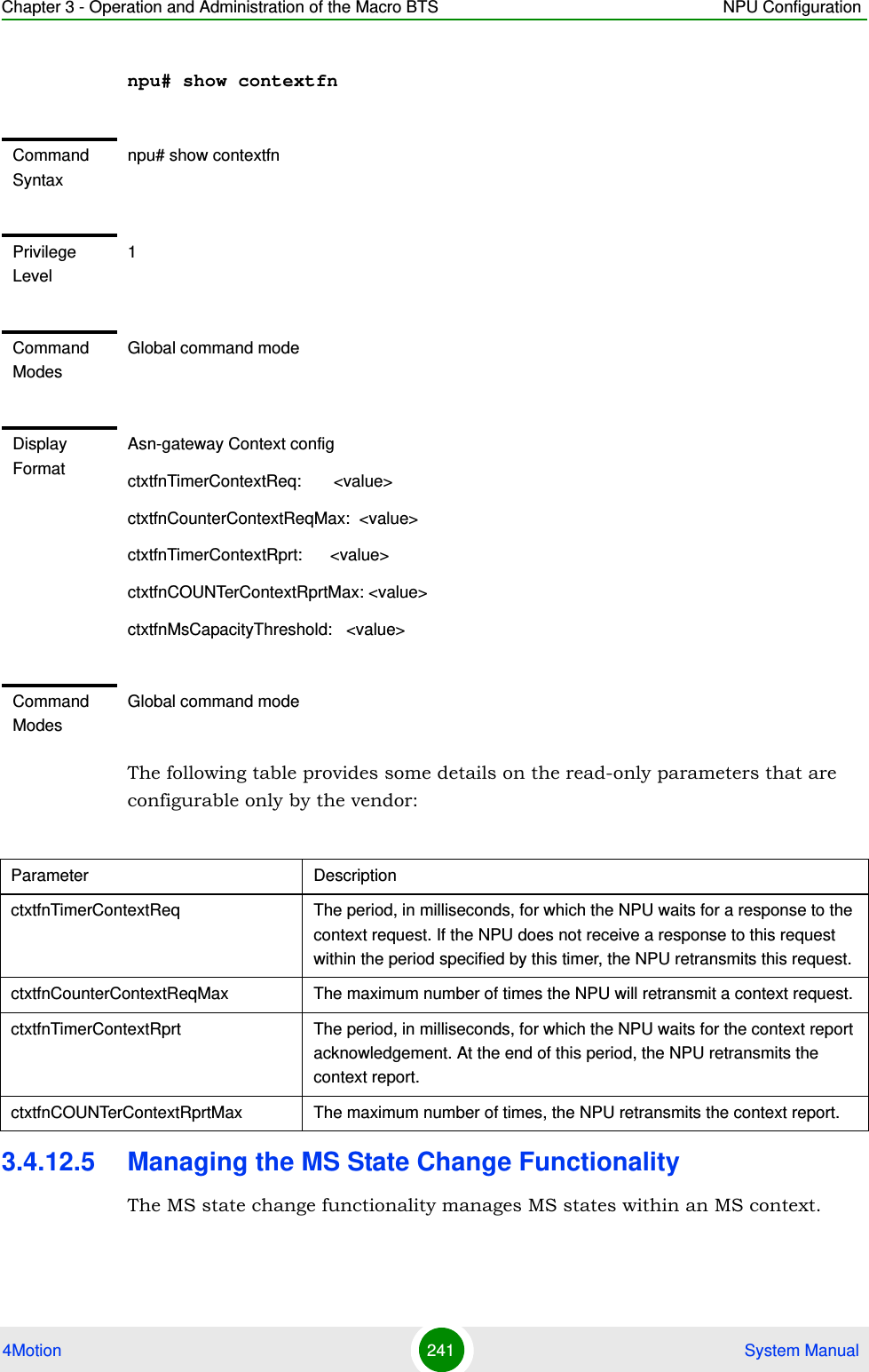
![Chapter 3 - Operation and Administration of the Macro BTS NPU Configuration4Motion 240 System Manual3.4.12.4.2 Restoring the Default Configuration Parameter for the Context FunctionTo restore the default configuration for the context function, run the following command:npu(config)# no contextfn [ms-capacity-threshold]3.4.12.4.3 Displaying Configuration Information for the Context Function To display configuration information for the context function, run the following command:Privilege Level10Syntax Description Parameter Description Presence Default ValuePossible Valuesms-capacity-threshold <integer (1-3000)>Maximal number of active MS that can be served by ASN-GW. Used as threshold for "no resource" reject and relevant alarm.Optional 500 1-3000Command ModesGlobal configuration modeNOTERefer to Section 3.4.12.4.1 for a description and default value of this parameters. Command Syntaxnpu(config)# no contextfn [ms-capacity-threshold]Privilege Level15Command ModesGlobal configuration mode](https://usermanual.wiki/Alvarion-Technologies/MICRO-25.Manual-p2/User-Guide-1329243-Page-140.png)
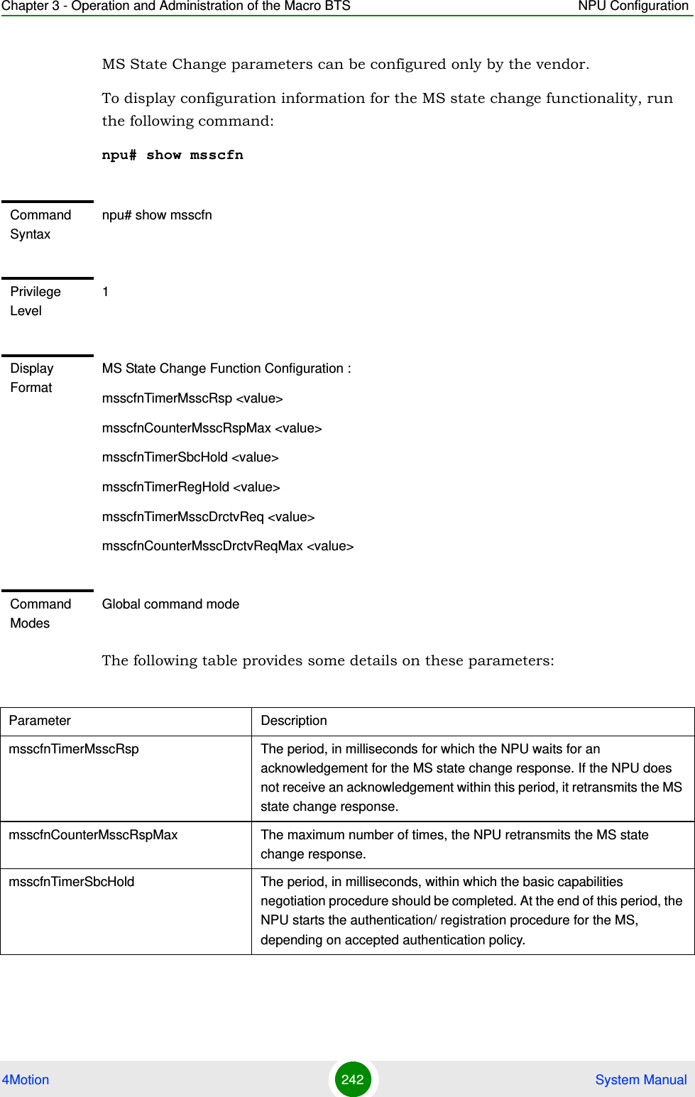
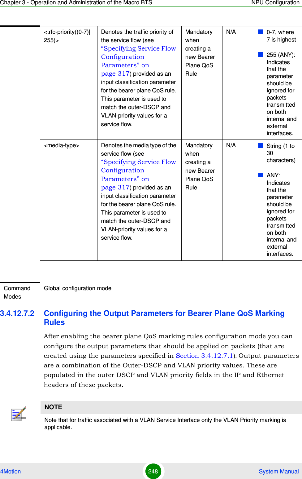
![Chapter 3 - Operation and Administration of the Macro BTS NPU Configuration4Motion 245 System Manual3Terminate the bearer plane QoS marking rules configuration mode (refer to Section 3.4.12.7.4)In addition, you can, at any time, display configuration information (refer to Section 3.4.12.7.6) or delete an existing bearer plane QoS marking rule (refer to Section 3.4.12.7.5). 3.4.12.7.1 Enabling the Bearer Plane QoS Marking Rule Configuration Mode\Creating a Bearer Plane QoS Marking RuleTo configure the parameters for the bearer plane QoS marking rules, first enable the bearer plane QoS marking rule configuration mode. Run the following command to enable the bearer plane QoS marking rules configuration mode. You can also use this command to create and enable the configuration mode for a new bearer plane QoS marking rule.npu(config)# bearerqos <qos-alias> [<intf-type((1<R3> - 0<R6>)| 255<ANY>)> <srvc-type(0<UGS> | 1<RTVR> | 2<NRTVR> | 3<BE> | 4<ERTVR> | 255<ANY>)> <trfc-priority((0-7)|255)> <media-type> ]If you use this command to create a new QoS marking rule, the configuration mode for this rule is automatically enabled, after which you can execute any of the following tasks:Configure the output parameters for bearer plane QoS marking rules (refer to Section 3.4.12.7.2)Restore the default parameters for bearer plane QoS marking rules (refer to Section 3.4.12.7.3)After executing the above tasks, you can terminate the bearer plane QoS marking rules configuration mode (refer to Section 3.4.12.7.4) and return to the global configuration mode.NOTEYou can display configuration information for the bearer plane QoS marking rules. For details, refer to Section 3.4.12.7.6.IMPORTANTAn error may occur if you provide an invalid value for any of these parameters. Refer the syntax description for more information about the appropriate values and format for configuring these parameters.](https://usermanual.wiki/Alvarion-Technologies/MICRO-25.Manual-p2/User-Guide-1329243-Page-145.png)
![Chapter 3 - Operation and Administration of the Macro BTS NPU Configuration4Motion 246 System ManualNOTEThe granularity of the QoS definition to be applied to packets transmitted on the bearer plane depends upon the number of parameters that you specify. If any parameter is to be excluded from the definition, specify the value 255 for that parameter.Command Syntaxnpu(config)# bearerqos <qos-alias> [<intf-type((1<R3> - 0<R6>)| 255<ANY>)> <srvc-type(0<UGS> | 1<RTVR> | 2<NRTVR> | 3<BE> | 4<ERTVR> | 255<ANY>)> <trfc-priority((0-7)|255)> <media-type>]Privilege Level10Syntax Description Parameter Description Presence Default ValuePossible Values<qos-alias> Denotes the QoS alias of the QoS marking rule for which you want to enable the bearer plane QoS marking rules configuration mode. If you want to create a new QoS marking rule, specify a new alias and define the type of interface, service, and traffic priority that is applicable for that rule.Mandatory N/A String (1 to 30 characters)](https://usermanual.wiki/Alvarion-Technologies/MICRO-25.Manual-p2/User-Guide-1329243-Page-146.png)
![Chapter 3 - Operation and Administration of the Macro BTS NPU Configuration4Motion 249 System ManualRun the following command to configure the output parameters for this bearer plane QoS marking rule:npu(config-bqos)# config [ outer-dscp <integer(0-63>] [vlan-priority <integer(0-7>] [qos enable]IMPORTANTEnable the bearer plane QoS marking rule that you are configuring. By default, all bearer plane QoS marking rules are disabled.NOTEYou can display configuration information for the bearer plane QoS marking rules. For details, refer to Section 3.4.12.7.6.IMPORTANTAn error may occur if you provide an invalid value for any of these parameters. Refer the syntax description for more information about the appropriate values and format for configuring these parameters.At least one parameter must be specified (the value is optional): The command npu(config-bqos)# config will return an Incomplete Command error.Command Syntaxnpu(config-bqos)# config [outer-dscp <integer(0-63>] [vlan-priority <integer(0-7>] [qos enable]Privilege Level10Syntax Description Parameter Description Presence Default ValuePossible Values[outer-dscp <integer(0-63>]Denotes the Differentiated Service Code Point (DSCP) value to be used for marking the packets, if the packet complies with the marking rules specified in Section 3.4.12.7.1.Optional 0 0-63](https://usermanual.wiki/Alvarion-Technologies/MICRO-25.Manual-p2/User-Guide-1329243-Page-149.png)