Alvarion Technologies MICRO-25 Microbase station transceiver User Manual 4Motion System Manual
Alvarion Technologies Ltd. Microbase station transceiver 4Motion System Manual
Contents
- 1. Manual p1
- 2. Manual p2
- 3. Manual p3
- 4. Manual p4
- 5. Manual p5
Manual p3
![Chapter 3 - Operation and Administration of the Macro BTS NPU Configuration4Motion 250 System Manual3.4.12.7.3 Restoring the Default Configuration Parameters for the Bearer Plane QoS Output Marking RulesRun the following command to restore the default configuration for this bearer plane QoS marking rule:npu(config-bqos)# no {outer-dscp | vlan-priority | qos enable}When you execute this command, it automatically disables this QoS marking rule.[vlan-priority <integer(0-7>]Denotes the VLAN priority to be assigned to the packets if the packet meets the requirements of the marking rules specified in Section 3.4.12.7.1.Optional 0 0-7, where 7 is the highest[qos enable] Indicates whether this QoS marking rule should be enabled. The absence of this flag indicates that this QoS flag is disabled. By default, a bearer plane QoS marking rule is disabled. If you enable this QoS marking rule, packets on bearer plane that were created using the parameters in Section 3.4.12.7.1, the Outer DSCP and VLAN Priority fields in the IP header and Ethernet header, respectively are populated with the values you specify for the outer-dscp and vlan-priority parameters.Optional By default, the QoS marking rule is disabled.The presence/absence of this flag indicates that this QoS flag is enabled/disabled. Command ModesBearer plane QoS marking rules configuration modeNOTERefer to Section 3.4.12.7.2 for a description and default values of these parameters.](https://usermanual.wiki/Alvarion-Technologies/MICRO-25.Manual-p3/User-Guide-1329244-Page-1.png)
![Chapter 3 - Operation and Administration of the Macro BTS NPU Configuration4Motion 251 System Manual3.4.12.7.4 Terminating the QoS Marking Rules Configuration ModeRun the following command to terminate the marking rules configuration mode:npu(config-bqos)# exit3.4.12.7.5 Deleting Bearer Plane QoS Marking RulesRun the following command to delete the a QoS marking rule:npu(config)# no bearerqos [<qos-alias>]Command Syntaxnpu(config-bqos)# no {outer-dscp | vlan-priority | qos enable}Privilege Level10Command ModesBearer plane QoS marking rules configuration modeCommand Syntaxnpu(config-bqos)# exitPrivilege Level10Command ModesBearer plane QoS marking rules configuration modeCAUTIONSpecify the QoS alias if you want to delete a specific bearer plane qoS marking rule. Otherwise all the configured bearer plane QoS marking rules are deleted except "int_default" and "ext_default" which cannot be deleted.Command Syntaxnpu(config)# no bearerqos [<qos-alias>]Privilege Level10](https://usermanual.wiki/Alvarion-Technologies/MICRO-25.Manual-p3/User-Guide-1329244-Page-2.png)
![Chapter 3 - Operation and Administration of the Macro BTS NPU Configuration4Motion 252 System Manual3.4.12.7.6 Displaying Configuration Information for the Bearer Plane QoS Marking Rules To display configuration information for specific or all bearer plane QoS marking rules, run the following command:npu# show bearerqos [<qos-alias>]Specify the QoS alias if you want to display configuration information for a particular bearer plane QoS marking rule. Do not specify a value for this parameter if you want to view configuration information for all bearer plane QoS marking rules.Syntax Description Parameter Description Presence Default ValuePossible Values[<qos-alias>] Denotes the QoS alias of the bearer QoS marking rule that you want to delete. Specify a value for this parameter if you want to delete a specific bearer QoS marking rule. Do not specify a value for this parameter if you want to delete all bearer QoS marking rules except "int_default" and "ext_default".Optional N/A StringCommand ModesGlobal configuration modeCommand Syntaxnpu# show bearerqos [<qos-alias>]Privilege Level1](https://usermanual.wiki/Alvarion-Technologies/MICRO-25.Manual-p3/User-Guide-1329244-Page-3.png)
![Chapter 3 - Operation and Administration of the Macro BTS NPU Configuration4Motion 253 System Manual3.4.12.8 Managing Service InterfacesA Service Interface defines the parameters of the interface used by the ASN-GW on the network side for services specified in the applicable Service Group.The following types of Service Interface are available:IP-IP: The Service Interface defines the parameters on the ASN-GW side of a point-to-point tunnel to be used for the applicable traffic.VLAN: The Service Interface defines the VLAN ID to be added/removed by the ASN-GW to/from the applicable traffic.QinQ: Applicable only for special applications requiring local support of unauthenticated mode. The QinQ Service Interface is applicable only for supporting VLAN CS Service Flows associated with a QinQ Service Group.Up to 10 Service Interfaces may be defined. Syntax Description Parameter Description Presence Default ValuePossible Values[<qos-alias>] Denotes the QoS alias of the bearer QoS marking rule that you want to display. Specify a value for this parameter if you want to display a specific bearer QoS marking rule. Do not specify a value for this parameter if you want to display all bearer QoS marking rules.Optional N/A StringDisplay FormatBearer QoS Configuration :qos-alias intf-type srvc-type trfc-priority media-type inner-dscp outer-dscp vlan-priority statusvoip <value> <value> <value> <value> <value> <value> enabledCommand ModesGlobal command mode](https://usermanual.wiki/Alvarion-Technologies/MICRO-25.Manual-p3/User-Guide-1329244-Page-4.png)
![Chapter 3 - Operation and Administration of the Macro BTS NPU Configuration4Motion 254 System Manual1Enable the Service Interface configuration mode for the selected Service Interface (refer to Section 3.4.12.8.1)2You can now execute any of the following tasks:»Configure one or more of the parameters of the Service Interface (refer to Section 3.4.12.8.2)»Restore the default values of the Service Interface parameters (refer to Section 3.4.12.8.3)» Terminate the Service Interface configuration mode (refer to Section 3.4.12.8.4)In addition, you can, at any time, display configuration information for one or all existing Service Interfaces (refer to Section 3.4.12.8.6) or delete an existing Service Interface (refer to Section 3.4.12.8.5). 3.4.12.8.1 Enabling the Service Interface Configuration Mode\Creating a Service InterfaceTo configure the parameters of a Service Interface, first enable the Service Interface configuration mode for the specific Service Interface. Run the following command to enable the Service Interface configuration mode. You can also use this command to create a new Service Interface. npu(config)# srvc-intf [<string>] [{IP-IP|VLAN|QinQ}]For example, to define a new IP-IP Service Interface named SI1, run the following command: npu(config)# srvc-intf SI1 IP-IPTo enable the configuration mode for an existing Service Interface named SI1, run the following command: npu(config)# srvc-intf SI1If you use this command to create a new Service Interface, the configuration mode for this Service Interface is automatically enabled.To configure a Service Interface:](https://usermanual.wiki/Alvarion-Technologies/MICRO-25.Manual-p3/User-Guide-1329244-Page-5.png)
![Chapter 3 - Operation and Administration of the Macro BTS NPU Configuration4Motion 255 System ManualAfter enabling the configuration mode for a Service Interface you can execute any of the following tasks:Configure one or more of the Service Interface parameters (refer to Section 3.4.12.8.2)Restore the default values of non-mandatory parameters of the Service Interface (refer to Section 3.4.12.8.3)After executing the above tasks, you can terminate the Service Interface configuration mode (refer to Section 3.4.12.8.4) and return to the global configuration mode.NOTEThe Bearer IP Interface (refer to “Configuring IP interfaces” on page 143) must be configured prior to creating IP-IP or VLAN service interfaces.Command Syntaxnpu(config)# srvc-intf [<string>] [{IP-IP|VLAN|QinQ}]Privilege Level10Syntax Description Parameter Description Presence Default ValuePossible Values[<string>] The Service Interface alias of the Service Interface for which you want to enable the configuration mode. If you want to create a new Service Interface, specify a new alias and define the type of service interface (see below).Mandatory N/A String (1 to 30 characters)[{IP-IP|VLAN|QinQ}]The Service Interface’s type. Optional IP-IP IP-IPVLANQinQ](https://usermanual.wiki/Alvarion-Technologies/MICRO-25.Manual-p3/User-Guide-1329244-Page-6.png)
![Chapter 3 - Operation and Administration of the Macro BTS NPU Configuration4Motion 256 System Manual3.4.12.8.2 Configuring Service Interface ParametersThis section describes the commands for:“Configuring Parameters for IP-IP Service Interface” on page 256“Configuring Parameters for VLAN Service Interface” on page 2573.4.12.8.2.1 Configuring Parameters for IP-IP Service InterfaceAfter enabling the IP-IP Service Interface configuration mode, run the following command to configure the IP-IP service interface parameters:This command shall configure one or more parameters of the IP-IP Service Interface.npu(config-srvcif-ipip)# config tunnel ([descr <string>] [srcaddr <ip4addr>] {dstaddr <ipv4addr>} [chksm])Command ModesGlobal configuration modeIMPORTANTAn error may occur if you provide an invalid value for any of these parameters. Refer to the syntax description for more information about the appropriate values and format for configuring these parameters.At least one parameter must be specified (the value is optional): The command npu(config-srvcif-ip-ip)# config tunnel will return an Incomplete Command error.Command Syntaxnpu(config-srvcif-ip-ip)# config tunnel ([descr <string>] [srcaddr <ip4addr>] {dstaddr <ipv4addr>} [chksm])Privilege Level10Syntax Description Parameter Description Presence Default ValuePossible Values[descr <string>] A description of the Service Interface.Optional null String (up to 70 characters)](https://usermanual.wiki/Alvarion-Technologies/MICRO-25.Manual-p3/User-Guide-1329244-Page-7.png)
![Chapter 3 - Operation and Administration of the Macro BTS NPU Configuration4Motion 257 System Manual3.4.12.8.2.2 Configuring Parameters for VLAN Service InterfaceAfter enabling the VLAN Service Interface configuration mode, run the following command to configure the VLAN service interface parameters:This command shall configure one or more parameters of the VLAN Service Interface.npu(config-srvcif-vlan)# config ([descr <string>] [vlan-id <size(1-9|11-4094>] [dflt-gw-ip <ipaddress> <mask>][srcaddr <ip4addr>]The source IP address that indicates the point of origination of the tunnel for the service interface.Must be set to the same address as the NPU Bearer IP Address.Optional 0.0.0.0 IP Address of Bearer Interface.{dstaddr <ipv4addr>}The destination IP address that indicates the point of termination of the tunnel for the service interface. Must be set to a valid IP address. The destination IP address of an existing Service Interface (if already configured to a valid value) cannot be changed.Optional 0.0.0.0 Valid IP Address.[chksm] Indicates that end-to-end checksumming mechanism on ServiceTunnel Interface is enabled.Optional By default, this feature is disabled.The presence/absence of this flag indicates that this feature is enabled/ disabled.Command ModesIP-IP Service Interface configuration mode](https://usermanual.wiki/Alvarion-Technologies/MICRO-25.Manual-p3/User-Guide-1329244-Page-8.png)
![Chapter 3 - Operation and Administration of the Macro BTS NPU Configuration4Motion 258 System ManualIMPORTANTAn error may occur if you provide an invalid value for any of these parameters. Refer to the syntax description for more information about the appropriate values and format for configuring these parameters.At least one parameter must be specified (the value is optional): The command npu(config-srvcif-vlan)# config will return an Incomplete Command error.Command Syntaxnpu(config-srvcif-vlan)# config ([descr <string>] [vlan-id <size(1-9|11-4094>] [dflt-gw-ip <ip address> <mask>]Privilege Level10Syntax Description Parameter Description Presence Default ValuePossible Valuesdescr <string> Aa description of the service interface.Optional null String (up to 70 characters)vlan-id <size(1-9|11-4094>]A Service Interface VLAN ID shall not conflict with other instances of Service Interface VLAN ID and VLAN IDs of Bearer, Local-Management, External-Management and AU Maintenance interfaces. Shall also not conflict with CVID of any transparent MS with L2 service.Must be set to a valid value other than the default (0). The VLAN ID of an existing Service Interface cannot be changed.Optional 0 1-9, 11-4094](https://usermanual.wiki/Alvarion-Technologies/MICRO-25.Manual-p3/User-Guide-1329244-Page-9.png)
![Chapter 3 - Operation and Administration of the Macro BTS NPU Configuration4Motion 259 System Manual3.4.12.8.2.3 Configuring Parameter for QinQ Service InterfaceAfter enabling the QinQ Service Interface configuration mode, run the following command to configure the QinQ service interface parameters:This command shall configure one or more parameters of the QinQ Service Interface.[dflt-gw-ip <ip address> <mask>]The IP Address and subnet mask of the Default Gateway.The IP address shall be unique among all the Host Interfaces IP's (Bearer, Local-Management, Internal-Management, External-Management) and existing instances of Service Interface’s Tunnel Destination IP Address and Default Gateway IP Address.Interface mask should be configured in such a way that the resulting subnet should not overlap with an existing Interface subnet (host interfaces, other service interfaces).Should be in the same subnet.with the IP Address of the DHCP server/proxy/relay to be assigned to a service group using this service interface. Must be changed from the default value. The Default Gateway IP Address of an existing service interface cannot be changed. The Subnet Mask of a service interface associated to a service group cannot be changed. Optional 0.0.0.0 255.255.255.0valid IP address and maskCommand ModesVLAN Service Interface configuration mode](https://usermanual.wiki/Alvarion-Technologies/MICRO-25.Manual-p3/User-Guide-1329244-Page-10.png)
![Chapter 3 - Operation and Administration of the Macro BTS NPU Configuration4Motion 260 System Manualnpu(config-srvcif-QinQ)# config ([descr <string>] [vlan-id <size(1-4094>])3.4.12.8.3 Restoring the Default Configuration Parameters for an IP-IP Service InterfaceRun the following command to restore the default configuration for IP-IP service interface chksm parameter:npu(config-srvcif-ipip)# no tunnel [chksm]IMPORTANTAn error may occur if you provide an invalid value for any of these parameters. Refer to the syntax description for more information about the appropriate values and format for configuring these parameters.At least one parameter must be specified (the value is optional): The command npu(config-srvcif-QinQ)# config will return an Incomplete Command error.Command Syntaxnpu(config-srvcif-QinQ)# config ([descr <string>] [vlan-id <size(1-4094>]])Privilege Level10Syntax Description Parameter Description Presence Default ValuePossible Valuesdescr <string> A description of the service interface.Optional null String (up to 70 characters)vlan-id <size(1-4094>]A Service Interface VLAN ID shall not conflict with other instances of Service Interface VLAN ID and VLAN IDs of Bearer, Local-Management and External-Management interfaces. Shall also not conflict with CVID of any transparent MS.Note that the default (0) is not a valid value.Optional 0 1-9, 11-4094Command ModesQinQ Service Interface configuration mode](https://usermanual.wiki/Alvarion-Technologies/MICRO-25.Manual-p3/User-Guide-1329244-Page-11.png)
![Chapter 3 - Operation and Administration of the Macro BTS NPU Configuration4Motion 261 System Manual3.4.12.8.4 Terminating a Service Interface Configuration ModeThis section describes the commands for:“Terminating the IP-IP Service Interface Configuration Mode” on page 261“Terminating the VLAN Service Interface Configuration Mode” on page 262“Terminating the QinQ Service Interface Configuration Mode” on page 2623.4.12.8.4.1 Terminating the IP-IP Service Interface Configuration ModeRun the following command to terminate the IP-IP service interface configuration mode:npu(config-srvcif-ipip)# exitNOTERefer to Section 3.4.12.8.2.1 for a description and default value of this parameter. Command Syntaxnpu(config-srvcif-ipip)# no tunnel [chksm]Privilege Level10Command ModesIP-IP Service Interface configuration modeCommand Syntaxnpu(config-srvcif-ipip)# exitPrivilege Level10Command ModesIP-IP Service interface configuration mode](https://usermanual.wiki/Alvarion-Technologies/MICRO-25.Manual-p3/User-Guide-1329244-Page-12.png)
![Chapter 3 - Operation and Administration of the Macro BTS NPU Configuration4Motion 262 System Manual3.4.12.8.4.2 Terminating the VLAN Service Interface Configuration ModeRun the following command to terminate the vlan service interface configuration mode:npu(config-srvcif-vlan)# exit3.4.12.8.4.3 Terminating the QinQ Service Interface Configuration ModeRun the following command to terminate the QinQ service interface configuration mode:npu(config-srvcif-QinQ)# exit3.4.12.8.5 Deleting a Service InterfaceYou can, at any time, run the following command to delete service interface:npu(config)# no srvc-intf [<intf-alias>]Command Syntaxnpu(config-srvcif-vlan)# exitPrivilege Level10Command ModesVLAN Service interface configuration modeCommand Syntaxnpu(config-srvcif-QinQ)# exitPrivilege Level10Command ModesQinQ Service interface configuration modeNOTEA Service Interface cannot be deleted if it is assigned to any Service Group.A QinQ Service Interface cannot be deleted if it is assigned to a Service Flow (with a VPWS-QinQ Service Group). For details refer to “Configuring Service Flows” on page 314.](https://usermanual.wiki/Alvarion-Technologies/MICRO-25.Manual-p3/User-Guide-1329244-Page-13.png)
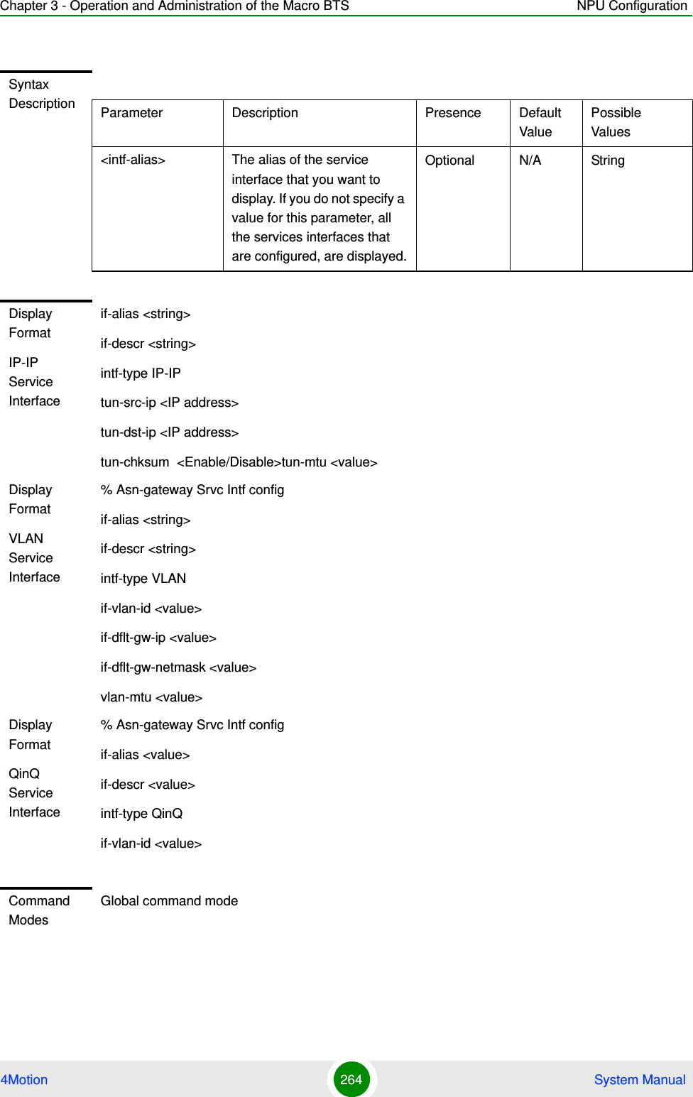
![Chapter 3 - Operation and Administration of the Macro BTS NPU Configuration4Motion 263 System Manual3.4.12.8.6 Displaying Configuration Information for the Service Interface To display configuration information for one or all service interfaces, run the following command:npu# show srvc-intf <intf-alias>Specify a value for the intf-alias parameter if you want to display configuration information for a particular service interface. Do not specify a value for this parameter if you want to view configuration information for all service interfaces.Command Syntaxnpu(config)# no srvc-intf [<intf-alias>]Privilege Level10Syntax Description Parameter Description Presence Default ValuePossible Values[<intf-alias>] The alias of the Service interface which needs to be deletedMandatory N/A StringCommand ModesGlobal configuration modeCommand Syntaxnpu# show srvc-intf <intf-alias>Privilege Level1](https://usermanual.wiki/Alvarion-Technologies/MICRO-25.Manual-p3/User-Guide-1329244-Page-14.png)
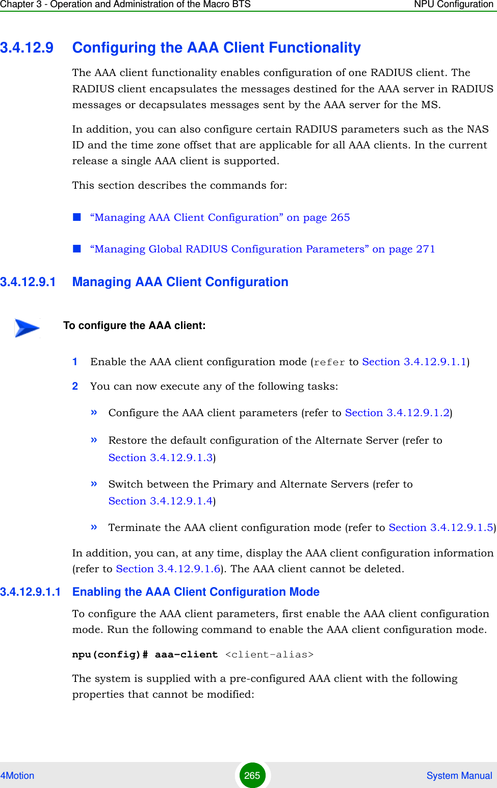
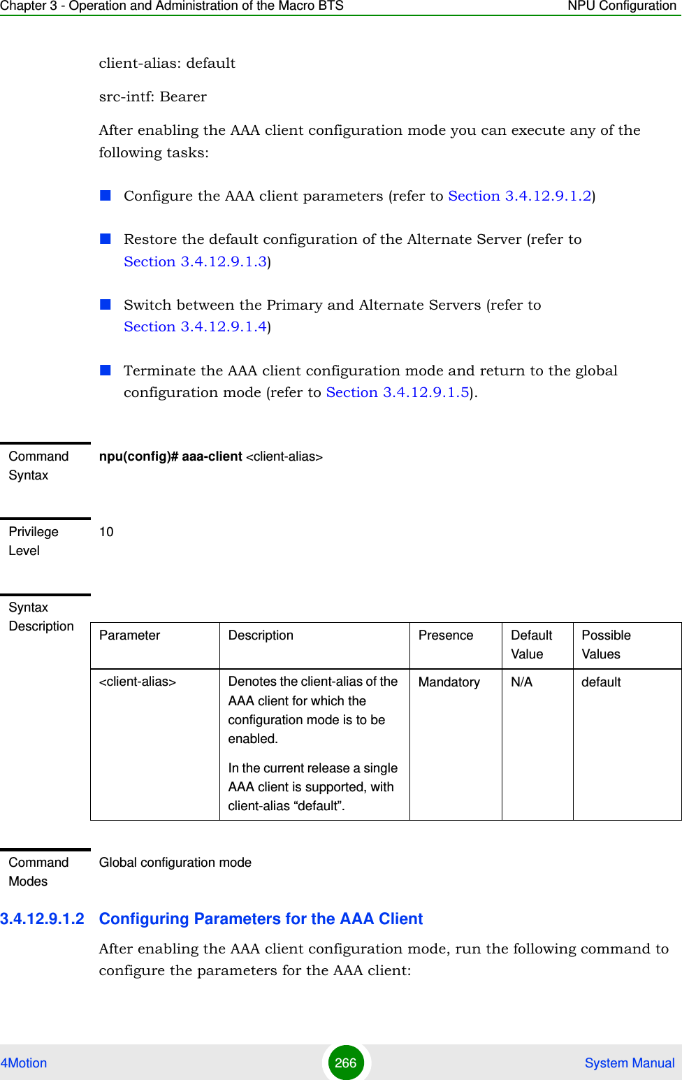
![Chapter 3 - Operation and Administration of the Macro BTS NPU Configuration4Motion 267 System Manualnpu(config-aaa)# config ([src-intf <ip-intf>] [primary-serveraddr <ipv4addr>] [alternate-serveraddr <ipv4addr>] [rad-sharedsecret <string>] [aaaRedundancy {Enable|Disable}] [rad-CallingStationId {Binary | UTF-8}])IMPORTANTAn error may occur if you provide an invalid value for any of these parameters. Refer the syntax description for more information about the appropriate values and format for configuring these parameters.IMPORTANTIf the bearer interface IP address is being modified after aaa-client configuration, you must re-configure the src-intf parameter to "bearer" so that the aaa-client will attach itself to the new bearer interface IP address.Command Syntaxnpu(config-aaa)# config ([src-intf <ip-intf>] [primary-serveraddr <ipv4addr>] [alternate-serveraddr <ipv4addr>] [rad-sharedsecret <string>] [aaaRedundancy {Enable|Disable}] [rad-CallingStationId {Binary | UTF-8}])Privilege Level10Syntax Description Parameter Description Presence Default ValuePossible Values[src-intf <ip-intf>] Indicates the interface providing RADIUS client functionality. Must be either the bearer interface or the external-management interface.Optional bearer bearerexternal-management[primary-serveraddr <ipv4addr>]Denotes IPv4 address of the primary AAA server.primary-serveraddr and alternate-serveraddr cannot be the same.primary-serveraddr and alternate-serveraddr cannot have IP address assigned to NPU IP interfaces.Mandatory 172.16.0.10 Valid IP Address](https://usermanual.wiki/Alvarion-Technologies/MICRO-25.Manual-p3/User-Guide-1329244-Page-18.png)
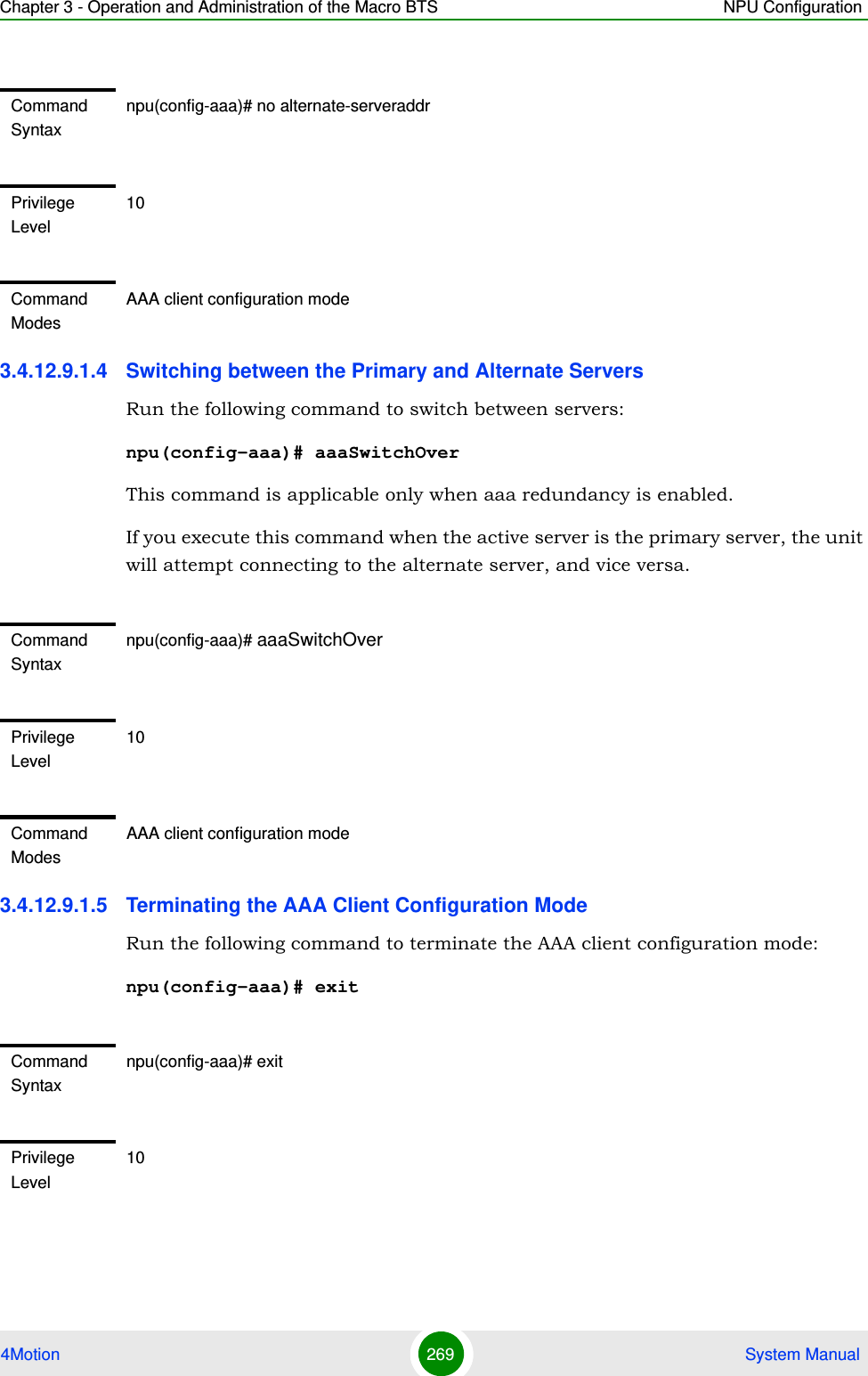
![Chapter 3 - Operation and Administration of the Macro BTS NPU Configuration4Motion 268 System Manual3.4.12.9.1.3 Restoring the Default Value of the Alternate ServerRun the following command to restore the default value (0.0.0.0) 0f the alternate server:npu(config-aaa)# no alternate-serveraddr[alternate-serveraddr <ipv4addr>]Denotes IPv4 address of the alternate (secondary) AAA server.0.0.0.0 means no alternate server.Must be set to a valid IP address if aaaRedundancy is enabled.Optional 0.0.0.0 Valid IP Address[rad-sharedsecret <string>]Denotes the shared secret between the AAA client and the AAA server(s). Optional default String (1 to 49 characters)[aaaRedundancy {Enable|Disable}] Indicates whether AAA server redundancy is supported.If enabled, the ASN-GW will try switching to the alternate server if the primary server does not respond, and vise versa.If enabled - the ip-address of the active server (primary or alternate) cannot be modified.Optional Disable EnableDisable[rad-CallingStationId {Binary | UTF-8}]The format of the MAC address used to define the Calling Station IDOptional UTF-8 BinaryUTF-8Command ModesAAA client configuration modeIMPORTANTThe alternate server cannot be cleared (restored to the default value) id aaaRedundancy is enabled.](https://usermanual.wiki/Alvarion-Technologies/MICRO-25.Manual-p3/User-Guide-1329244-Page-19.png)
![Chapter 3 - Operation and Administration of the Macro BTS NPU Configuration4Motion 270 System Manual3.4.12.9.1.6 Displaying Configuration and Status Information for the AAA ClientTo display one or all AAA clients, run the following command:npu# show aaa-client <client-alias>In the current release a single AAA client is supported. The client-alias is default.Command ModesAAA client configuration modeCommand Syntaxnpu# show aaa-client <client-alias>Privilege Level1Syntax Description Parameter Description Presence Default ValuePossible Values[<client-alias>] Denotes the client-alias for which the associated AAA client information is to be displayed. In the current release the client-alias of the supported client is default.Optional N/A default or nullDisplay FormatAAA-client :Src-intf(IP) :Primary-ServerAddr :Alternate ServerAddr :Radius Shared Secret : <not available for display>Active AAA server :AAA Redundancy :Station ID Format :](https://usermanual.wiki/Alvarion-Technologies/MICRO-25.Manual-p3/User-Guide-1329244-Page-21.png)
![Chapter 3 - Operation and Administration of the Macro BTS NPU Configuration4Motion 271 System ManualIn addition to configurable parameters, the currently Active AAA server (Primary/Alternate) is also displayed.3.4.12.9.2 Managing Global RADIUS Configuration ParametersGlobal RADIUS configuration parameters for AAA clients determine how AAA clients should send access requests. This section describes the commands to be used for: “Configuring Global RADIUS Parameters” on page 271“Restoring the Default Global RADIUS Configuration Parameters” on page 273“Displaying Global RADIUS Configuration Parameters” on page 2743.4.12.9.2.1 Configuring Global RADIUS ParametersTo configure the global RADIUS configuration parameters to be used for all AAA clients, run the following command:npu(config)# radius <[accessreq-retries <retransmissions>] [accessreq-interval <timeout>] [nasid <nas-identifier>] [timezone-offset <time-offset(0-86400)>] [mtu <framed mtu size(1020-2000)>][RadiusAtrbtTypeServiceProfileName <AtrbtTypeId(1-255)>] [vlan-classf-bit-align {msbShift|lsb}][alrmAaaSwitchoverRetryFailThrshld(1-250)>]>Command ModesGlobal command modeNOTEYou can display configuration information for global RADIUS parameters. For details, refer to Section 3.4.12.9.2.3IMPORTANTAn error may occur if you provide an invalid value for any of these parameters. Refer the syntax description for more information about the appropriate values and format for configuring these parameters.Command Syntaxnpu(config)# radius <[accessreq-retries <retransmissions>] [accessreq-interval <timeout>] [nasid <nas-identifier>] [timezone-offset <time-offset(0-86400)>] [mtu <framed mtu size(1020-2000)>] [RadiusAtrbtTypeServiceProfileName <AtrbtTypeId(1-255)>] [alrmAaaSwitchoverRetryFailThrshld(1-250)>] [vlan-classf-bit-align {msbShift|lsb}]>](https://usermanual.wiki/Alvarion-Technologies/MICRO-25.Manual-p3/User-Guide-1329244-Page-22.png)
![Chapter 3 - Operation and Administration of the Macro BTS NPU Configuration4Motion 272 System ManualPrivilege Level10Syntax Description Parameter Description Presence Default ValuePossible Values[accessreq-retries <retransmissions>]Denotes the maximum number of times the AAA client can resend the access request.Optional 3 0-5[accessreq-interval <timeout>]Denotes the interval, in seconds, after which the AAA client can resend the access request.Optional 500 10-100000[nasid <nas-identifier>]Denotes the unique identifier of the ASNGW NAS. Sent in Access Request message only if configured. Should be in FQDN format.Optional null String (up to 64 characters)[timezone-offset <time-offset(0-86400)>]Denotes the time zone offset, in seconds, from GMT at the NAS.Optional 0 0-86400[mtu <framed mtu size(1020-2000)>]Denotes the MTU to be used for the AAA client functionality.Optional 2000 1020-2000[RadiusAtrbtTypeServiceProfileName <AtrbtTypeId(1-255)>]Denotes the RADIUS attribute in which the ASN-GW shall expect to get the service profile name. For example, configure 11 if AAA uses Filter ID as the container of service profile name,Use only unassigned freetext-type RADIUS attributes.Optional 11 1-255](https://usermanual.wiki/Alvarion-Technologies/MICRO-25.Manual-p3/User-Guide-1329244-Page-23.png)
![Chapter 3 - Operation and Administration of the Macro BTS NPU Configuration4Motion 273 System Manual3.4.12.9.2.2 Restoring the Default Global RADIUS Configuration ParametersTo restore the default global RADIUS configuration used for AAA clients, run the following command:npu(config)# no radius [accessreq-retries] [accessreq-interval] [nasid] [timezone-offset] [mtu][alrmAaaSwitchoverRetryFailThrshld(1-250)>]Threshold to set alarm when the number of AAA switchover "unsuccessful access to primary + secondary" failed events for a measured period (PM interval of 15 minutes) exceeds the provisioned number.Optional 250 1 - 250[vlan-classf-bit-align {msbShift | lsb}]Defines how to transfer VLAN ID between R3 and R6:If msbShift is selected: a. When transferring classifier VID value from R3 side to R6 side, the binary value of the 12 least significant bits in R3 TLV will be copied and pasted as most significant bits in R6 TLV. b. When transferring classifier VID value from R6 to R3, the binary value of the 12 the most significant bits in R6 TLV will be copied and pasted as the 12 least significant bits in R3 TLV.if lsb is selected: The whole 16 bit value of the relevant TLV will be transferred without any change when transferring classifier VID value from R3 side to R6 side and from R6 to R3.Optional msbShift msbShiftlsbCommand ModesGlobal configuration mode](https://usermanual.wiki/Alvarion-Technologies/MICRO-25.Manual-p3/User-Guide-1329244-Page-24.png)
![Chapter 3 - Operation and Administration of the Macro BTS NPU Configuration4Motion 274 System Manual3.4.12.9.2.3 Displaying Global RADIUS Configuration ParametersTo display global RADIUS configuration parameters used for all AAA clients, run the following command:npu# show radiusNOTERefer Section 3.4.12.9.2.1 for a description and default values of these parameters. Command Syntaxnpu(config)# no radius [accessreq-retries] [accessreq-interval] [nasid] [timezone-offset] [mtu]Privilege Level10Command ModesGlobal configuration modeCommand Syntaxnpu# show radiusPrivilege Level1Display Format TimeOut <value>accessReq-retries <value> NAS-ID <value> TimeZone Offset <value> framed MtuSize <value> Profile AtrbtType <value>alrmAaaSwitchoverRetryFailThrshld <value> VLAN Bit Alignment <value>Command ModesGlobal command mode](https://usermanual.wiki/Alvarion-Technologies/MICRO-25.Manual-p3/User-Guide-1329244-Page-25.png)
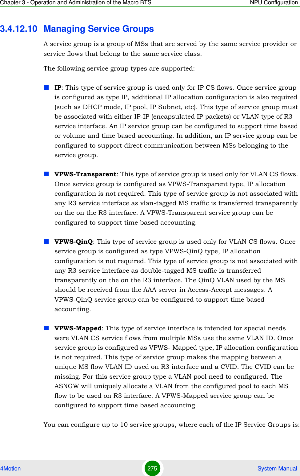
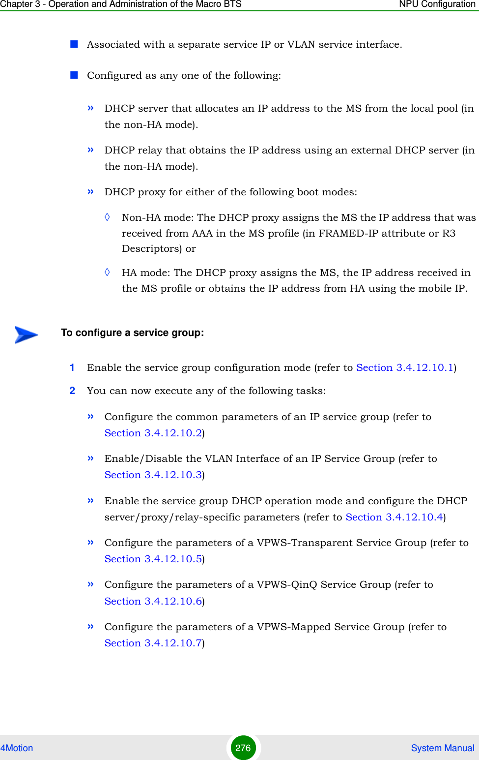
![Chapter 3 - Operation and Administration of the Macro BTS NPU Configuration4Motion 277 System Manual»Terminate the service group configuration mode (refer to Section 3.4.12.10.8)In addition, you can, at any time, display configuration information (refer to Section 3.4.12.10.10) or delete an existing service group (refer to Section 3.4.12.10.9). 3.4.12.10.1 Enabling the Service Group Configuration Mode\ Creating a New Service GroupTo configure the parameters for the service group, first enable the service group configuration mode. Run the following command to enable the service group configuration mode or create the service group.npu(config)# srvc-grp <grp-alias> [ServiceGrpType {IP | VPWS-QinQ | VPWS-Transparent | VPWS-Mapped}]If you use this command to create a new service group, the configuration mode for this group is automatically enabled after which you can configure or restore the default parameters for this service group.After enabling the service group configuration mode, you can execute any of the following tasks:Configure the common parameters for an IP service group (refer to Section 3.4.12.10.2)Enable/Disable the VLAN Interface of an IP Service Group (refer to Section 3.4.12.10.3)Enable the service group operation mode and configure the DHCP server/proxy/relay-specific parameters (refer to Section 3.4.12.10.4)Configure the parameters of a VPWS-Transparent Service Group (refer to Section 3.4.12.10.5)Configure the parameters of a VPWS-Transparent Service Group (refer to Section 3.4.12.10.6)Configure the parameters of a VPWS-Transparent Service Group (refer to Section 3.4.12.10.7)After executing these tasks, you can terminate the service group configuration mode (refer to Section 3.4.12.10.8).](https://usermanual.wiki/Alvarion-Technologies/MICRO-25.Manual-p3/User-Guide-1329244-Page-28.png)
![Chapter 3 - Operation and Administration of the Macro BTS NPU Configuration4Motion 278 System Manual3.4.12.10.2 Configuring Common Parameters of an IP Service GroupAfter enabling the service group configuration mode for an IP service group, run the following command to configure common parameters for the service group:npu(config-srvcgrp)# config {{[srvcif-alias <service interface>] [waitdhcp-holdtime <timeout>] [dhcp-ownaddr <ipv4addr>]} | NOTEYou can display configuration information for specific or all service groups. For details, refer to Section 3.4.12.11.2.Command Syntaxnpu(config)# srvc-grp <grp-alias> [ServiceGrpType {IP | VPWS-QinQ | VPWS-Transparent | VPWS-Mapped}]Privilege Level10Syntax Description Parameter Description Presence Default ValuePossible Valuessrvc-grp <grp-alias>Denotes the group-alias of the service group for which the service group configuration mode is to be enabled. If you want to create a new service group, specify the group alias to be assigned to the service group.Mandatory N/A String (1 to 30 characters)[ServiceGrpType {IP | VPWS-QinQ | VPWS-Transparent | VPWS-Mapped} ]The Service group’s type. Optional IP IPVPWS-QinQVPWS-TransparentVPWS-MappedCommand ModesGlobal configuration mode](https://usermanual.wiki/Alvarion-Technologies/MICRO-25.Manual-p3/User-Guide-1329244-Page-29.png)
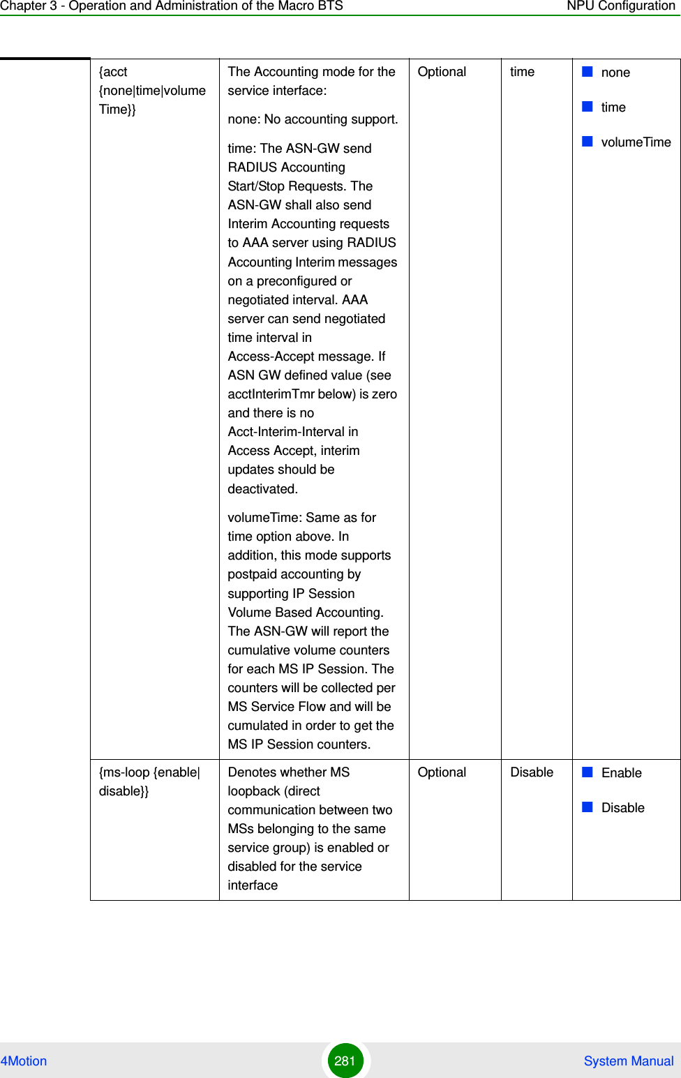
![Chapter 3 - Operation and Administration of the Macro BTS NPU Configuration4Motion 279 System Manual{server|proxy|relay} |{[<acct (none|time|volumeTime)>]}|{[<ms-loop (enable|disable)>] | [acctInterimTmr <integer(0|5-1600)>]}This commands comprises 5 sub-commands:1npu(config-srvcgrp)# config {[srvcif-alias <service interface>] [waitdhcp-holdtime <timeout>] [dhcp-ownaddr <ipv4addr>]} 2npu(config-srvcgrp)# config {server|proxy|relay}3npu(config-srvcgrp)# config {[<acct (none|time|volumeTime)>]}4npu(config-srvcgrp)# config {[<ms-loop (enable|disable)>]}5npu(config-srvcgrp)# config {[acctInterimTmr <integer(0|5-1600)>]}NOTEYou can display configuration information for the service group. For details, refer to Section 3.4.12.11.2.IMPORTANTAn error may occur if you provide an invalid value for any of these parameters. Refer the syntax description for more information about the appropriate values and format for configuring these parameters.Command Syntaxnpu(config-srvcgrp)# config {{[srvcif-alias <service interface>] [waitdhcp-holdtime <timeout>] [dhcp-ownaddr <ipv4addr>]} | {server|proxy|relay} |{[<acct (none|time|volumeTime)>]}|{[<ms-loop (enable|disable)>] | [acctInterimTmr <integer(0|5-1600)>]}Privilege Level10Syntax Description Parameter Description Presence Default ValuePossible Values[srvcif-alias <service interface>]Denotes the pre-defined IP or VLAN service interface alias to be used as the data path for traffic towards the core network.Note that a Service Interface alias can be associated only to a single Service Group.Mandatory N/A String](https://usermanual.wiki/Alvarion-Technologies/MICRO-25.Manual-p3/User-Guide-1329244-Page-30.png)
![Chapter 3 - Operation and Administration of the Macro BTS NPU Configuration4Motion 280 System Manual[waitdhcp-holdtime <timeout>]Denotes the period, in seconds, for which the NPU waits for an IP address allocation trigger (MIP registration request / DHCP discover) from the MS. If you specify the value of this parameter as 0, no timer is started and the NPU will wait infinitely for the IP address allocation trigger.Optional 0 0-86400[dhcp-ownaddr <ipv4addr>]Denotes the IPv4 address of the DHCP server/ relay/ proxy.Must be unique in the network.For a service group using a VLAN service interface, should be in same subnet with the Default Gateway configured for the service interface associated with the service group. Subnet mask is taken as the default subnet mask i.e 255.255.255.0.Note: In DHCP Server mode, the DHCP server IP address must be in the same subnet but outside the range allocated for users address pool as provisioned in the DHCP Server.Mandatory N/A Valid IP Address{server|proxy|relay}Mode of IP address allocation used for subscribers: DHCP Server/ Proxy/ Relay.Mandatory N/A dhcp-serverdhcp-proxydhcp-relay](https://usermanual.wiki/Alvarion-Technologies/MICRO-25.Manual-p3/User-Guide-1329244-Page-31.png)
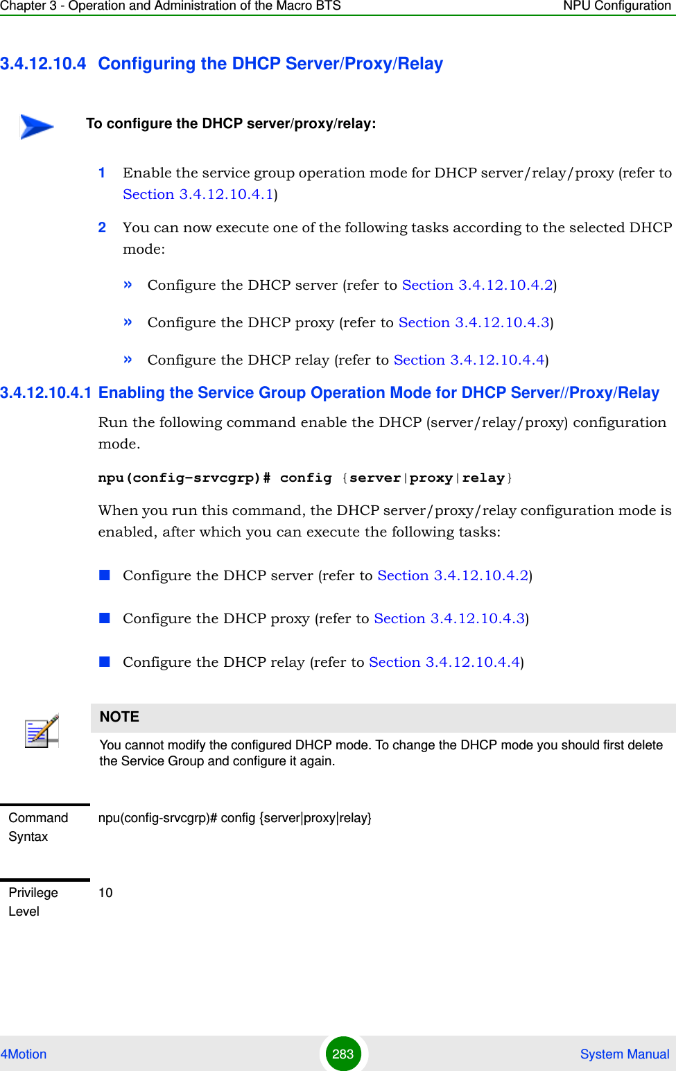
![Chapter 3 - Operation and Administration of the Macro BTS NPU Configuration4Motion 282 System Manual3.4.12.10.3 Enabling/Disabling VLAN Service Interface for an IP Service GroupThis command is applicable only for an IP service group associated with a VLAN service interface.Run the following commands to enable/disable the creation of a data-path for a VLAN Service:To enable: npu(config-srvcgrp)# set vlan-enableTo disable: npu(config-srvcgrp)# no vlan-enable[acctInterimTmr <integer(0|5-1600)>]Applicable only if acct (see above) mode is set to either time or volumeTime. The default interval in minutes for Accounting Interim reports to be used if Acct-Interim-Interval is not received from the AAA server.Value “0” means interim reports are deactivated unless Acct-Interim-Interval is sent by the AAA server in Access Accept messages.Optional 5 05-1600Command ModesIP Service group configuration modeIMPORTANTThe default is disabledCommand Syntaxnpu(config-srvcgrp)# set vlan-enablenpu(config-srvcgrp)# no vlan-enablePrivilege Level10Command ModesIP Service group configuration mode](https://usermanual.wiki/Alvarion-Technologies/MICRO-25.Manual-p3/User-Guide-1329244-Page-33.png)
![Chapter 3 - Operation and Administration of the Macro BTS NPU Configuration4Motion 284 System Manual3.4.12.10.4.2 Configuring the DHCP ServerAfter enabling the service group operation mode for the DHCP server, you can execute any of the following tasks:“Configuring DHCP Server Parameters” on page 284“Restoring Configuration Parameters for the DHCP Server” on page 288“Configuring Exclude IP Addresses for the DHCP Server” on page 288“Deleting Exclude IP Addresses for the DHCP Server” on page 2893.4.12.10.4.2.1Configuring DHCP Server ParametersRun the following command to configure the DHCP server:npu(config-srvcgrp-dhcpserver)# config ([pool-minaddr <string>] [pool-maxaddr <string>] [pool-subnet <string>] [dflt-gwaddr <string>] [lease-interval <integer(24-4294967295)>] [renew-interval <integer>] [rebind-interval <integer>] [dnssrvr-addr <string>] [offerreuse-holdtime <integer>] [opt60 <string(30)>] [opt43 {[Name <string(64)>] [Value <string(64)>]}] [Sname <string(64)>] [File <string(128)>] [dnssrvr-addr2 <string>])Syntax Description Parameter Description Presence Default ValuePossible Values{server|proxy|relay}Indicates whether the service group operation mode is to be enabled for the DHCP server, proxy or relay.Mandatory N/A serverproxyrelayCommand ModesService group configuration modeNOTEBefore executing these tasks, ensure that you have enabled the DHCP server configuration mode. For details, refer to “Enabling the Service Group Operation Mode for DHCP Server//Proxy/Relay” on page 283.](https://usermanual.wiki/Alvarion-Technologies/MICRO-25.Manual-p3/User-Guide-1329244-Page-35.png)
![Chapter 3 - Operation and Administration of the Macro BTS NPU Configuration4Motion 285 System ManualIMPORTANTAn error may occur if you provide an invalid value for any of these parameters. Refer the syntax description for more information about the appropriate values and format for configuring these parameters.Command Syntaxnpu(config-srvcgrp-dhcpserver)# config ([pool-minaddr <string>] [pool-maxaddr <string>] [pool-subnet <string>] [dflt-gwaddr <string>] [lease-interval <integer(24-4294967295)>] [renew-interval <integer>] [rebind-interval <integer>] [dnssrvr-addr <string>] [offerreuse-holdtime <integer>] [opt60 <string(30)>] [opt43 {[Name <string(64)>] [Value <string(64)>]}] [Sname <string(64)>] [File <string(128)>] [dnssrvr-addr2 <string>])Privilege Level10Syntax Description Parameter Description Presence Default ValuePossible Values[pool-minaddr <string>]Denotes the minimum (lowest) IP address of the address pool to be used for address allocation for MSs from this Service Group.DHCP address in the pool shall not overlap with the DHCP address pool defined in an existing service group and with ip addresses of host interfaces (Bearer, External mgmt, Internal mgmt and Local mgmt).Optional 0.0.0.0 Valid IP Address](https://usermanual.wiki/Alvarion-Technologies/MICRO-25.Manual-p3/User-Guide-1329244-Page-36.png)
![Chapter 3 - Operation and Administration of the Macro BTS NPU Configuration4Motion 286 System Manual[[pool-maxaddr <string>] Denotes the maximum (highest) IP address of the address pool configuration.DHCP address in the pool shall not overlap with the DHCP address pool defined in an existing service group and with ip addresses of host interfaces (Bearer, External mgmt, Internal mgmt and Local mgmt).Optional 255.255.255.255Valid IP Address[pool-subnet <string>] The IP subnet mask to be provided by local DHCP Service with IP address for MSs from this Service Group.Optional 255.255.255.255IP subnet[dflt-gwaddr <string>] IP address of Default Gateway to be provided by local DHCP Service with IP address for MS from this Service Group.Optional 0.0.0.0 (none)Valid IP Address[lease-interval <integer(24-4294967295)>]Lease time in seconds of IP address allocated for MS from this Service Group.Optional 86400 24-4294967295[renew-interval <integer>]Denotes the period, after which, the MS can request for renewal of the lease which has expired. Specify the value of this parameter as a percentage of the lease-interval parameter.The renew-interval must be lower than rebind-interval.Optional 50 1-100[rebind-interval <integer>] Denotes the rebind interval maintained as a percentage of the lease interval. This is passed to the MS (DHCP client).Optional 75 1-99](https://usermanual.wiki/Alvarion-Technologies/MICRO-25.Manual-p3/User-Guide-1329244-Page-37.png)
![Chapter 3 - Operation and Administration of the Macro BTS NPU Configuration4Motion 287 System Manual[dnssrvr-addr <string>]IP Address of the first DNS Server to be provisioned to MS from this Group.Optional 0.0.0.0 (none)Valid IP Address[offerreuse-holdtime <integer>]Denotes the Offer Reuse time in seconds of IP address offered to MS from this Service Group.Optional 5 1-120[opt60 <string(30)>] Configures option 60.An empty string (null) means that DHCP Option 60 is disabled.Optional null String (up to 30 characters).Null (empty string) disables Option 60.[opt43 {[Name <string(64)>]Configures option 43 NameOptional InternetGatewayDevice.ManagementServer.URLString (up to 64 characters)[Value <string(64)>] Configures option 43 ValueOptional empty stringString (up to 64 characters)[Sname <string(64)>] Configures the server host name. This parameter is sent in dhcp-offer / dhcp-ack messages and may be used by certain CPEs.Optional empty stringString (up to 64 characters)[File <string(128)>] Configures the boot file name. This parameter is sent in dhcp-offer / dhcp-ack messages and may be used by certain CPEs.Optional empty stringString (up to 128 characters)[dnssrvr-addr2 <string>]IP Address of the second DNS Server to be provisioned to MS from this Group.Optional 0.0.0.0 (none)Valid IP addressCommand ModesService Group-DCHP server configuration mode](https://usermanual.wiki/Alvarion-Technologies/MICRO-25.Manual-p3/User-Guide-1329244-Page-38.png)
![Chapter 3 - Operation and Administration of the Macro BTS NPU Configuration4Motion 288 System Manual3.4.12.10.4.2.2Restoring Configuration Parameters for the DHCP Server Run the following command to restore the default values of one or several DHCP server parameters. This command can be used to delete the DNS server address configuration (if specified).npu(config-srvcgrp-dhcpserver)# no [lease-interval] [renew-interval] [rebind-interval] [dnssrvr-addr] [offerreuse-holdtime] [dnssrvr-addr2]Specify one or several parameters to restore the specified parameters to their default values. Do not specify any parameter to restore all of these parameters to their default values.3.4.12.10.4.2.3Configuring Exclude IP Addresses for the DHCP ServerRun the following command to configure exclude IP addresses for the DHCP server:npu(config-srvcgrp-dhcpserver)# exclude-addr <no. of Addrs (1-9)> <ipv4addr> [<ipv4addr>] ….In each command you may add up to 9 IP addresses to be excluded. The total number of excluded IP addresses is up to a maximum of 16384.NOTERefer to Section 3.4.12.10.4.2.1 for a description and default values of these parameters. Command Syntaxnpu(config-srvcgrp-dhcpserver)# no [lease-interval] [renew-interval] [rebind-interval] [dnssrvr-addr] [offerreuse-holdtime] [dnssrvr-addr2]Privilege Level10Command ModesService group-DHCP server configuration modeIMPORTANTAn error may occur if you provide an invalid IP address. Refer the syntax description for more information about the appropriate values and format for configuring this parameters.](https://usermanual.wiki/Alvarion-Technologies/MICRO-25.Manual-p3/User-Guide-1329244-Page-39.png)
![Chapter 3 - Operation and Administration of the Macro BTS NPU Configuration4Motion 289 System Manual3.4.12.10.4.2.4Deleting Exclude IP Addresses for the DHCP ServerRun the following command to delete one or several excluded IP addresses for the DHCP server: npu(config-srvcgrp-dhcpserver)# no exclude-addr <no. of Addrs (1-9)> <ipv4addr> [<ipv4addr>] …Run the following command (without specifying the parameters) to delete all excluded IP addresses for the DHCP server: npu(config-srvcgrp-dhcpserver)# no exclude-addrThe deleted exclude IP addresses are no longer excluded when the DHCP server allocates the IP addresses. That is, the server may allocate these IP addresses to the MS.Command Syntaxnpu(config-srvcgrp-dhcpserver)# exclude-addr <no. of Addrs (1-9)> <ipv4addr> [<ipv4addr>] ….Privilege Level10Syntax Description Parameter Description Presence Default ValuePossible Values<no. of Addrs (1-9)>The number of IP addresses to be excludedMandatory N/A 1-9<ipv4addr> Denotes the exclude IP address that will not be assigned to an MS by the DHCP server.The number of IP address entries must match the value defined by the no. of Addrs parameter.Mandatory N/A Valid IP addressCommand ModesService group-DCHP server configuration modeCommand Syntaxnpu(config-srvcgrp-dhcpserver)# no exclude-addr no. of Addrs (1-9)> <ipv4addr> [<ipv4addr>] …](https://usermanual.wiki/Alvarion-Technologies/MICRO-25.Manual-p3/User-Guide-1329244-Page-40.png)
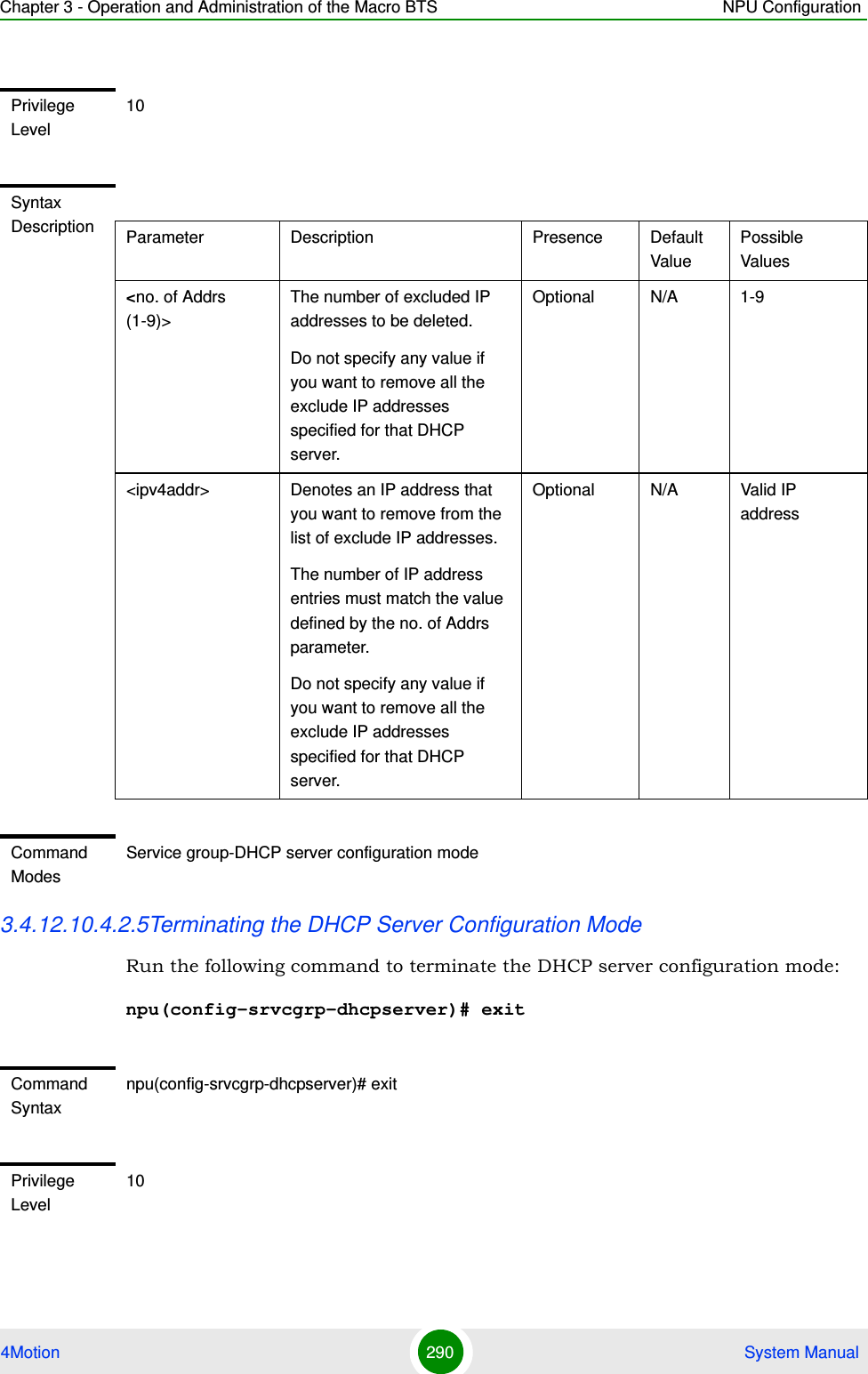
![Chapter 3 - Operation and Administration of the Macro BTS NPU Configuration4Motion 291 System Manual3.4.12.10.4.3 Configuring the DHCP ProxyAfter enabling the service group operation mode for the DHCP proxy, you can execute the following tasks:“Specifying DHCP Proxy Configuration Parameters” on page 291“Restoring the Default Configuration Parameters for the DHCP Proxy” on page 294“Terminating the DHCP Proxy Configuration Mode” on page 2953.4.12.10.4.3.1Specifying DHCP Proxy Configuration ParametersRun the following command to configure the DHCP proxy:npu(config-srvcgrp-dhcpproxy)# config ([offerreuse-holdtime <integer>] [lease-interval <integer>] [dnssrvr-addr <string>] [pool-subnet <string>] [dflt-gwaddr <string>] [renew-interval <integer>] [rebind-interval <integer>] [opt60 <string(30)>] [opt43 {[Name <string(64)>] [Value <string(64)>]}] [Sname <string(64)>] [File <string(128)>]) [dnssrvr-addr2 <string>]Command ModesService group-DHCP server configuration modeIMPORTANTAn error may occur if you provide an invalid value for any of these parameters. Refer the syntax description for more information about the appropriate values and format for configuring these parameters.Command Syntaxnpu(config-srvcgrp-dhcpproxy)# config ([offerreuse-holdtime <integer>] [lease-interval <integer>] [dnssrvr-addr <string>] [pool-subnet <string>] [dflt-gwaddr <string>] [renew-interval <integer>] [rebind-interval <integer>] [opt60 <string(30)>] [opt43 {[Name <string(64)>] [Value <string(64)>]}] [Sname <string(64)>] [File <string(128)>] [dnssrvr-addr2 <string>])Privilege Level10](https://usermanual.wiki/Alvarion-Technologies/MICRO-25.Manual-p3/User-Guide-1329244-Page-42.png)
![Chapter 3 - Operation and Administration of the Macro BTS NPU Configuration4Motion 292 System ManualSyntax Description Parameter Description Presence Default ValuePossible Values[offerreuse-holdtime <integer>] Denotes the duration in seconds within which the MS should send a DHCP request to accept the address sent by the NPU.If the MS does not accept the address within this period, the MS is deregistered.Optional 5 0-120[lease-interval <integer>]Lease time in seconds of IP address allocated for MS from this Service Group. In the Proxy mode, this value is used if appropriate parameter is not received in RADIUS Access-Accept.Optional 86400 24 - 4294967295[dnssrvr-addr <string>] IP Address of the first DNS Server to be provisioned to MS from this Group. In the Proxy mode, this value is used if appropriate parameter is not received in RADIUS Access-Accept.Optional 0.0.0.0 (none)Valid IP Address[pool-subnet <string>] The IP subnet mask to be provided by local DHCP Service with IP address for MSs from this Service Group. In the Proxy mode, this value is used if appropriate parameter is not received in RADIUS Access-Accept.Optional 255.255.255.255IP subnet](https://usermanual.wiki/Alvarion-Technologies/MICRO-25.Manual-p3/User-Guide-1329244-Page-43.png)
![Chapter 3 - Operation and Administration of the Macro BTS NPU Configuration4Motion 293 System Manual[dflt-gwaddr <string>] IP address of Default Gateway to be provided by local DHCP Service with IP address for MS from this Service Group. In the Proxy mode, this value is used if appropriate parameter is not received in RADIUS Access-Accept.Optional 0.0.0.0 (none)Valid IP Address[renew-interval <integer>]Denotes the period, after which, the MS can request for renewal of the lease which has expired. Specify the value of this parameter as a percentage of the lease-interval parameter.This value is used if appropriate parameter is not received in RADIUS Access-Accept.Optional 50 1-100[rebind-interval <integer>]Denotes the rebind interval maintained as a percentage of the lease interval. This is passed to the MS (DHCP client).This value is used if appropriate parameter is not received in RADIUS Access-Accept.Optional 75 1-99[opt60 <string(30)>] Configures option 60. Optional null String (up to 30 characters)[opt43 {[Name <string(64)>]Configures option 43 NameOptional InternetGatewayDevice.ManagementServer.URLString (up to 64 characters)[Value <string(64)>] Configures option 43 ValueOptional empty stringString (up to 64 characters)](https://usermanual.wiki/Alvarion-Technologies/MICRO-25.Manual-p3/User-Guide-1329244-Page-44.png)
![Chapter 3 - Operation and Administration of the Macro BTS NPU Configuration4Motion 294 System Manual3.4.12.10.4.3.2Restoring the Default Configuration Parameters for the DHCP ProxyRun the following command to restore the default values of one or several DHCP proxy parameters. This command can also be used to delete the configured DNS server address (if specified).npu(config-srvcgrp-dhcpproxy)# no [offerreuse-holdtime] [lease-interval] [dnssrvr-addr][renew-interval] [rebind-interval] [dnssrvr-addr2]Specify one or several parameters to restore the specified parameters to their default values. Do not specify any parameter to restore all of these parameters to their default values.[Sname <string(64)>] Configures the proxy host name. This parameter is sent in dhcp-offer / dhcp-ack messages and may be used by certain CPEs.Optional empty stringString (up to 64 characters)[File <string(128)>] Configures the boot file name. This parameter is sent in dhcp-offer / dhcp-ack messages and may be used by certain CPEs.Optional empty stringString (up to 128 characters)[dnssrvr-addr2 <string>]IP Address of the second DNS Server to be provisioned to MS from this Group. In the Proxy mode, this value is used if appropriate parameter is not received in RADIUS Access-Accept.Optional 0.0.0.0 (none)Valid IP addressCommand ModesService group-DHCP proxy configuration modeNOTERefer Section 3.4.12.10.4.3.1 for a description and default values of these parameters.](https://usermanual.wiki/Alvarion-Technologies/MICRO-25.Manual-p3/User-Guide-1329244-Page-45.png)
![Chapter 3 - Operation and Administration of the Macro BTS NPU Configuration4Motion 295 System Manual3.4.12.10.4.3.3Terminating the DHCP Proxy Configuration ModeRun the following command to terminate the DHCP proxy configuration mode: npu(config-srvcgrp-dhcpproxy)# exit3.4.12.10.4.4 Configuring the DHCP RelayAfter enabling the service group operation mode for the DHCP relay, you can execute any of the following tasks:“Configuring the DHCP Relay Parameters” on page 295“Terminating the DHCP Relay Configuration Mode” on page 3013.4.12.10.4.4.1Configuring the DHCP Relay ParametersRun the following command to configure the DHCP server address for the DHCP relay:npu(config-srvcgrp-dhcprelay)# config ([server-addr <ipV4Addr>] [{EnableOpt82|DisableOpt82}])Command Syntaxnpu(config-srvcgrp-dhcpproxy)# no [offerreuse-holdtime] [lease-interval] [dnssrvr-addr][renew-interval] [rebind-interval] [dnssrvr-addr2]Privilege Level10Command ModesService group-DHCP proxy configuration modeCommand Syntaxnpu(config-srvcgrp-dhcpproxy)# exitPrivilege Level10Command ModesService group-DHCP proxy configuration mode](https://usermanual.wiki/Alvarion-Technologies/MICRO-25.Manual-p3/User-Guide-1329244-Page-46.png)
![Chapter 3 - Operation and Administration of the Macro BTS NPU Configuration4Motion 296 System Manual3.4.12.10.4.4.2Configuring the DHCP Relay Option 82 ParametersIf Option 82 for the DHCP Relay is enabled, run the following command to configure suboptions of option 82 of DHCP messages:npu(config-srvcgrp-dhcprelay-Opt82)# config ([Subopt1value {Default|MSID|BSID|NASID|NASIP|Full-NAI|Domain|asciiMsID|asciiBsID|asciiBsMac|AsciiFrStrng <string(32)>|BinFrStrng <string(32)>}] [Subopt2value {Default|MSID|BSID|NASID|NASIP|Full-NAI|Domain|asciiMsID|asciiBsID|asciiBsMac|AsciiFrStrng <string(32)>|BinFrStrng <string(32)>}] [Subopt6value {Default|MSID|BSID|NASID|NASIP|Full-NAI|Domain|AsciiFrStrng <string(32)>|BinFrStrng <string(32)>}] [{Subopt7value [service-type] [vendor-specific] [session-timeout]}] [{EnableUnicast|DisableUnicast}])IMPORTANTAn error may occur if you provide an invalid value for the DHCP server address. Refer to the syntax description for more information about the appropriate values and format for configuring this parameters.Command Syntaxnpu(config-srvcgrp-dhcprelay)# config ([server-addr <ipV4Addr>] [{EnableOpt82|DisableOpt82}])Privilege Level10Syntax Description Parameter Description Presence Default ValuePossible Values[server-addr <ipv4addr>]Denotes the IP address of the external DHCP server. Must be configured to a valid IP address.Optional 0.0.0.0 Valid IP Address[{EnableOpt82|DisableOpt82}]Denotes whether DHCP option 82 is enabled or disabled.Optional DisableOpt82EnableOpt82DisableOpt82Command ModesService group-DHCP relay configuration mode](https://usermanual.wiki/Alvarion-Technologies/MICRO-25.Manual-p3/User-Guide-1329244-Page-47.png)
![Chapter 3 - Operation and Administration of the Macro BTS NPU Configuration4Motion 297 System ManualIMPORTANTFor DhcpRlOpt82SubOpt1BinFrstrng value, enter hex string without spaces. If Opt82Unicast is enabled then DHCP relay agent appends option 82 to all DHCP messages (unicast and broadcast). If Opt82Unicast is disabled (default) then DHCP relay agent appends option 82 only to broadcast DHCP request messages.Command Syntaxnpu(config-srvcgrp-dhcprelay-Opt82)# config ([Subopt1value {Default|MSID|BSID|NASID|NASIP|Full-NAI|Domain|asciiMsID|asciiBsID|asciiBsMac|AsciiFrStrng <string(32)>|BinFrStrng <string(32)>}] [Subopt2value {Default|MSID|BSID|NASID|NASIP|Full-NAI|Domain|asciiMsID|asciiBsID|asciiBsMac|AsciiFrStrng <string(32)>|BinFrStrng <string(32)>}] [Subopt6value {Default|MSID|BSID|NASID|NASIP|Full-NAI|Domain|AsciiFrStrng <string(32)>|BinFrStrng <string(32)>}] [{Subopt7value [service-type] [vendor-specific] [session-timeout]}] [{EnableUnicast|DisableUnicast}])Privilege Level10](https://usermanual.wiki/Alvarion-Technologies/MICRO-25.Manual-p3/User-Guide-1329244-Page-48.png)
![Chapter 3 - Operation and Administration of the Macro BTS NPU Configuration4Motion 298 System ManualSyntax Description Parameter Description Presence Default ValuePossible Values[Subopt1value {Default|MSID|BSID|NASID|NASIP|Full-NAI|Domain|asciiMsID|asciiBsID|asciiBsMac|AsciiFrStrng <string(32)>|BinFrStrng <string(32)>}]Configures the suboption 1 (Agent Circuit ID) of DHCP option 82.For AsciiFrStrng (string enter up to 32 characters,For BinFrStrng (string enter a string of up to 32 hexadecimal digits (no spaces).Optional Not Set DefaultMSIDBSIDNASIDNASIPFull-NAI Domain asciiMsIDasciiBsIDasciiBsMacAsciiFrStrng (string32)BinFrStrng (string32)](https://usermanual.wiki/Alvarion-Technologies/MICRO-25.Manual-p3/User-Guide-1329244-Page-49.png)
![Chapter 3 - Operation and Administration of the Macro BTS NPU Configuration4Motion 299 System Manual[Subopt2value {Default|MSID|BSID|NASID|NASIP|Full-NAI|Domain|asciiMsID|asciiBsID|asciiBsMac|AsciiFrStrng <string(32)>|BinFrStrng <string(32)>}Configures the suboption 2 (Agent Remote ID) of DHCP option 82. For AsciiFrStrng (string enter up to 32 characters,For BinFrStrng (string enter a string of up to 32 hexadecimal digits (no spaces).Optional Not Set DefaultMSIDBSIDNASIDNASIPFull-NAI DomainasciiMsIDasciiBsID asciiBsMacAsciiFrStrng (string32)BinFrStrng (string32)[Subopt6value {Default|MSID|BSID|NASID|NASIP|Full-NAI|Domain|AsciiFrStrng <string(32)>|BinFrStrng <string(32)>}] Configures the suboption 6 (Agent Subscriber ID)of DHCP option 82.For AsciiFrStrng (string enter up to 32 characters,For BinFrStrng (string enter a string of up to 32 hexadecimal digits (no spaces).Optional Not Set DefaultMSIDBSIDNASIDNASIPFull-NAI Domain AsciiFrStrng (string32)BinFrStrng (string32)](https://usermanual.wiki/Alvarion-Technologies/MICRO-25.Manual-p3/User-Guide-1329244-Page-50.png)
![Chapter 3 - Operation and Administration of the Macro BTS NPU Configuration4Motion 300 System Manual3.4.12.10.4.4.3Removing the DHCP Relay suboption valuesRun the following command to remove one, several or all of the Suboption values configured by the user for DHCP Option 82.npu(config-srvcgrp-dhcprelay-opt82)# no [Subopt1value] [Subopt2value] [Subopt6value] [Subopt7value][{Subopt7value [service-type] [vendor-specific] [session-timeout]}]Configures the suboption 7 of DHCP option 82.Allows enabling/disabling the use of suboption 7 by specifying it. In addition, allows enabling/disabling the following attributes (by specifying attributes to be enabled) if suboption 7 is enabled:service-type (attribute 6)vendor-specific (attribute 26)session-timeout (attribute 27)Optional[{EnableUnicast|DisableUnicast}])Indicates whether the Unicast parameter is enabled or disabled.Optional Disable EnableDisableCommand ModeService group-DHCP relay-option 82 configuration modeCommand Syntaxnpu(config-srvcgrp-dhcprelay-opt82)# no [Subopt1value] [Subopt2value] [Subopt6value] [Subopt7value]Privilege Level10](https://usermanual.wiki/Alvarion-Technologies/MICRO-25.Manual-p3/User-Guide-1329244-Page-51.png)
![Chapter 3 - Operation and Administration of the Macro BTS NPU Configuration4Motion 301 System Manual3.4.12.10.4.4.4Terminating the DHCP Relay Configuration ModeRun the following command to terminate the DHCP relay configuration mode for this service group: npu(config-srvcgrp-dhcprelay)# exit3.4.12.10.5 Configuring the Parameters of a VPWS-Transparent Service GroupAfter enabling the service group configuration mode for a VPWS-Transparent service group, run the following command to configure the accounting parameters for the service group:npu(config-srvcgrp-VPWS)# config {acct {none|time} | acctInterimTmr <integer(0|5-1600)>}Syntax Description Parameter Description Presence Default ValuePossible Valuesno [Subopt1value] [Subopt2value] [Subopt6value] [Subopt7value]Indicates the removal status of DHCP Option 82 suboptions.If no suboption is specified, the values of all suboptions will be removed.Optional N/A N/ACommand ModeService group-DHCP relay-Option 82 configuration modeCommand Syntaxnpu(config-srvcgrp-dhcprelay)# exitPrivilege Level10Command ModesService group-DHCP relay configuration modeNOTEYou can display configuration information for the service group. For details, refer to Section 3.4.12.11.2.](https://usermanual.wiki/Alvarion-Technologies/MICRO-25.Manual-p3/User-Guide-1329244-Page-52.png)
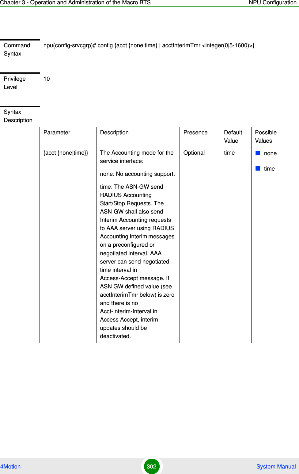
![Chapter 3 - Operation and Administration of the Macro BTS NPU Configuration4Motion 303 System Manual3.4.12.10.6 Configuring the Parameters of a VPWS-QinQ Service GroupAfter enabling the service group configuration mode for a VPWS-QinQ service group, run the following command to configure the accounting parameters for the service group:npu(config-srvcgrp-VPWS)# config {acct {none|time} | acctInterimTmr <integer(0|5-1600)>}[acctInterimTmr <integer(0|5-1600)>]Applicable only if acct (see above) mode is set to time. The default interval in minutes for Accounting Interim reports to be used if Acct-Interim-Interval is not received from the AAA server.Value “0” means interim reports are deactivated unless Acct-Interim-Interval is sent by the AAA server in Access Accept messages.Optional 5 05-1600Command ModesVPWS-Transparent Service group configuration modeNOTEYou can display configuration information for the service group. For details, refer to Section 3.4.12.11.2.Command Syntaxnpu(config-srvcgrp)# config {acct {none|time} | acctInterimTmr <integer(0|5-1600)>}Privilege Level10](https://usermanual.wiki/Alvarion-Technologies/MICRO-25.Manual-p3/User-Guide-1329244-Page-54.png)
![Chapter 3 - Operation and Administration of the Macro BTS NPU Configuration4Motion 304 System ManualSyntax DescriptionParameter Description Presence Default ValuePossible Values{acct {none|time}} The Accounting mode for the service interface:none: No accounting support.time: The ASN-GW send RADIUS Accounting Start/Stop Requests. The ASN-GW shall also send Interim Accounting requests to AAA server using RADIUS Accounting Interim messages on a preconfigured or negotiated interval. AAA server can send negotiated time interval in Access-Accept message. If ASN GW defined value (see acctInterimTmr below) is zero and there is no Acct-Interim-Interval in Access Accept, interim updates should be deactivated.Optional time nonetime[acctInterimTmr <integer(0|5-1600)>]Applicable only if acct (see above) mode is set to time. The default interval in minutes for Accounting Interim reports to be used if Acct-Interim-Interval is not received from the AAA server.Value “0” means interim reports are deactivated unless Acct-Interim-Interval is sent by the AAA server in Access Accept messages.Optional 5 05-1600Command ModesVPWS-QinQ Service group configuration mode](https://usermanual.wiki/Alvarion-Technologies/MICRO-25.Manual-p3/User-Guide-1329244-Page-55.png)
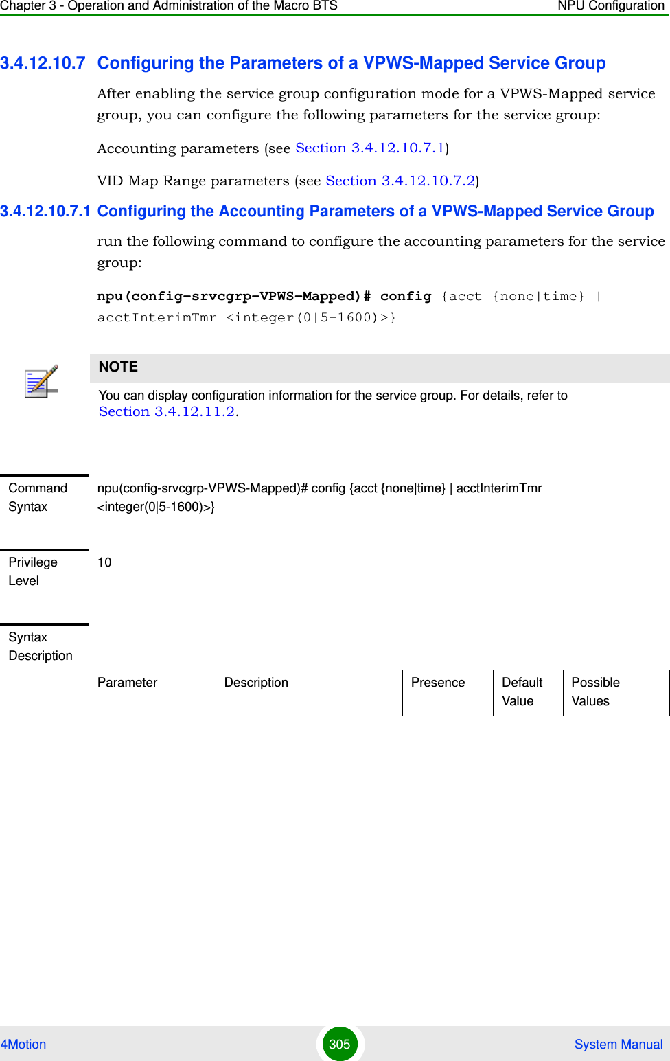
![Chapter 3 - Operation and Administration of the Macro BTS NPU Configuration4Motion 306 System Manual3.4.12.10.7.2 Configuring the VID Map Range Parameters of a VPWS-Mapped Service Grouprun the following commands to configure the vid-map-range parameters for the service group:{acct {none|time}} The Accounting mode for the service interface:none: No accounting support.time: The ASN-GW sends RADIUS Accounting Start/Stop Requests. The ASN-GW also sends Interim Accounting requests to AAA server using RADIUS Accounting Interim messages on a preconfigured or negotiated interval. AAA server can send negotiated time interval in Access-Accept message. If ASN GW defined value (see acctInterimTmr below) is zero and there is no Acct-Interim-Interval in Access Accept, interim updates should be deactivated.Optional time nonetime[acctInterimTmr <integer(0|5-1600)>]Applicable only if acct (see above) mode is set to time. The default interval in minutes for Accounting Interim reports to be used if Acct-Interim-Interval is not received from the AAA server.Value “0” means interim reports are deactivated unless Acct-Interim-Interval is sent by the AAA server in Access Accept messages.Optional 5 05-1600Command ModesVPWS-Mapped Service group configuration mode](https://usermanual.wiki/Alvarion-Technologies/MICRO-25.Manual-p3/User-Guide-1329244-Page-57.png)
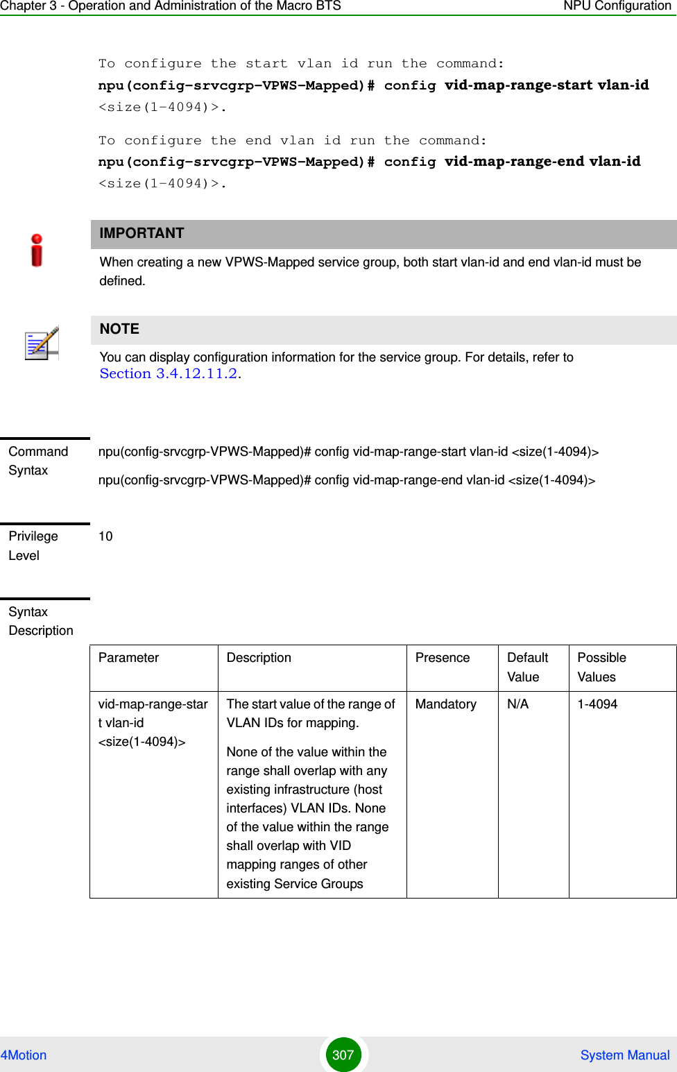
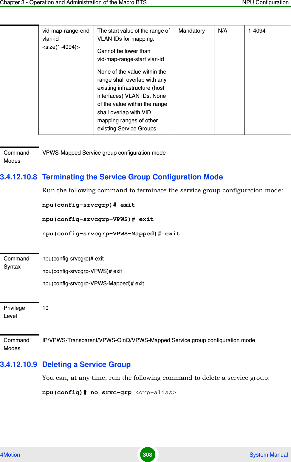
![Chapter 3 - Operation and Administration of the Macro BTS NPU Configuration4Motion 309 System Manual3.4.12.10.10Displaying Configuration Information for the Service Group To display configuration information for one service group or for all service groups, run the following command:npu# show srvc-grp [<grp-alias>]NOTEA Service Group cannot be deleted if it is assigned to a Service Flow. For details refer to “Configuring Service Flows” on page 314.To delete a VLAN service group (associated with a VLAN service interface), first execute the "no vlan-enable" command (refer to Section 3.4.12.10.3).Command Syntaxnpu(config)# no srvc-grp <grp-alias>Privilege Level10Syntax Description Parameter Description Presence Default ValuePossible Values<grp-alias> Denotes the group-alias for which the service group to be deleted. Mandatory N/A StringCommand ModesGlobal configuration modeCommand Syntaxnpu# show srvc-grp [<grp-alias>]Privilege Level1](https://usermanual.wiki/Alvarion-Technologies/MICRO-25.Manual-p3/User-Guide-1329244-Page-60.png)
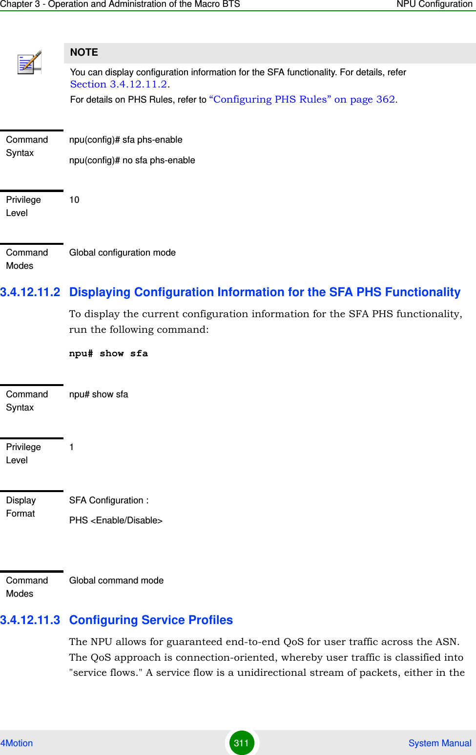
![Chapter 3 - Operation and Administration of the Macro BTS NPU Configuration4Motion 310 System Manual3.4.12.11 Configuring the Service Flow Authorization FunctionalityThe Service Flow Authorization (SFA) functionality handles creation/ maintenance of pre-provisioned service flows for MS. It maps the AAA parameters (service profile name) received from the AAA server to pre-configured WiMAX-specific QoS parameters in the NPU. The SFA functionality enables you to configure multiple service profiles with multiple service flows and classification rules.This section describes the commands to be used for:“Configuring the SFA PHS Functionality” on page 310“Displaying Configuration Information for the SFA PHS Functionality” on page 311“Configuring Service Profiles” on page 311“Configuring Classification Rules” on page 3303.4.12.11.1 Configuring the SFA PHS Functionality To configure the SFA functionality with respect to PHS Rules, run the following command:To enable PHS: npu(config)# sfa phs-enableTo disable PHS: npu(config)# no sfa phs-enableThe default configuration is PHS Disable. Syntax Description Parameter Description Presence Default ValuePossible Values[<grp-alias>] Denotes the group-alias for which the service group to be displayed. If no grp-alias is specified, the parameters of all service groups will be displayed.Optional N/A StringDisplay FormatAccording to Service Group type and (for IP Service Group) the configured DHCP mode.](https://usermanual.wiki/Alvarion-Technologies/MICRO-25.Manual-p3/User-Guide-1329244-Page-61.png)
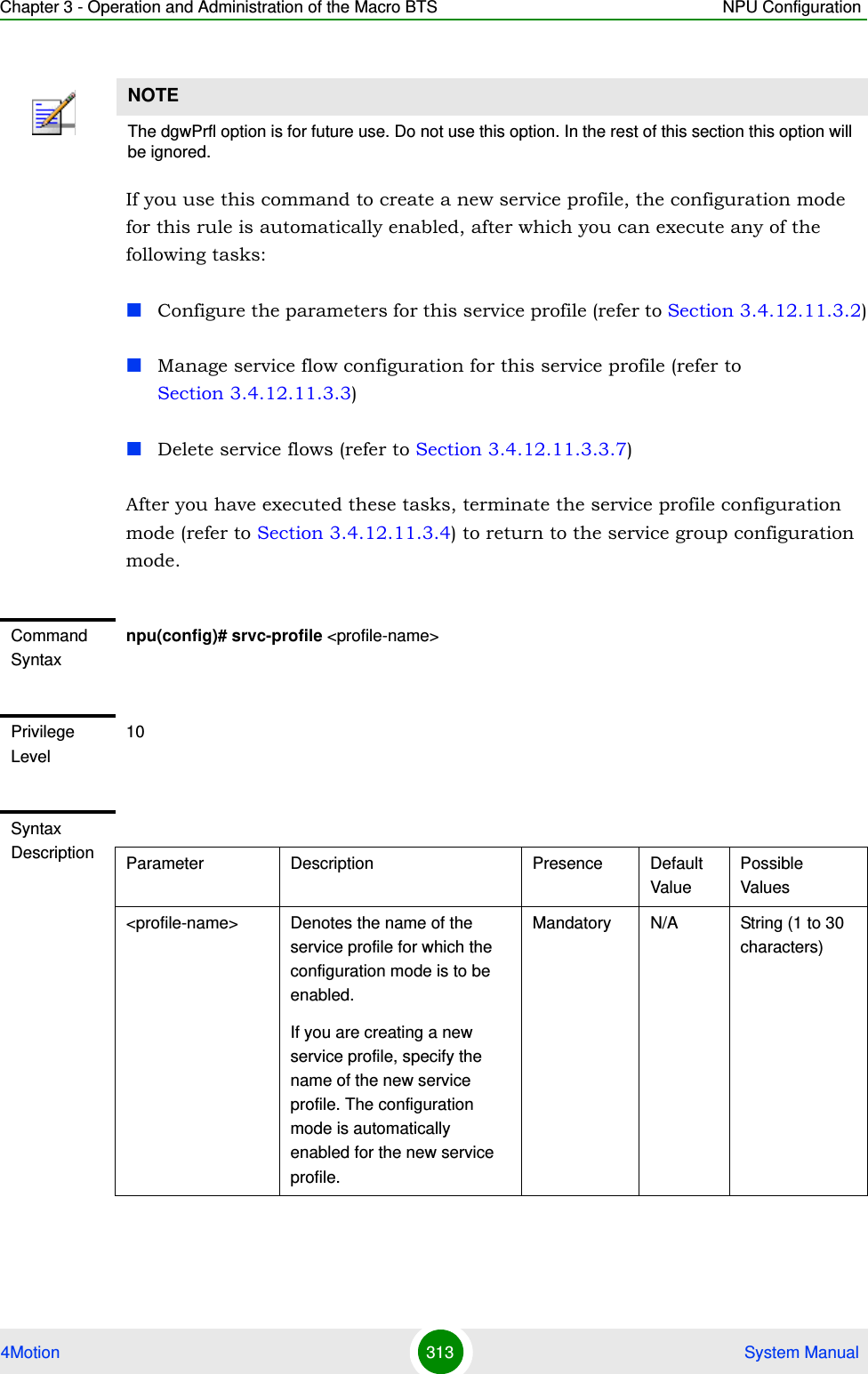
![Chapter 3 - Operation and Administration of the Macro BTS NPU Configuration4Motion 312 System Manualdownlink or uplink direction, associated with a certain set of QoS requirements such as maximum latency. The QoS requirements for service flows are derived from "service profiles" defined by the operator. A service profile is a set of attributes shared by a set of service flows. For instance, an operator might define a service profile called "Internet Gold" that will include QoS and other definitions to be applied to service flows associated with users subscribed to the operator's "Internet Gold" service package.The factory default configuration includes an ‘empty” (no defined Service Flows) Service Profile with the name Default. If enabled, it will be used if profile descriptor is missing in service provisioning or if received profile descriptor is disabled (unauthenticated mode). Up to 63 additional Service Profiles may be created.1Enable the service profile configuration mode (refer to Section 3.4.12.11.3.1)2You can now execute any of the following tasks:»Configure the parameters for this service profile (refer to Section 3.4.12.11.3.2)»Manage service flow configuration for this service profile (refer to Section 3.4.12.11.3.3)»Delete service flows (refer to Section 3.4.12.11.3.3.7)3Terminate the service profile configuration mode (refer to Section 3.4.12.11.3.4)You can, at any time, display configuration information (refer to Section 3.4.12.11.3.5) or delete an existing service profile (refer to Section 3.4.12.11.3.6). 3.4.12.11.3.1 Enabling the Service Profile Configuration Mode\Creating a New Service ProfileTo configure the parameters for a service profile, first enable the service profile configuration mode. Run the following command to enable the service profile configuration mode. You can also use this command to create a new service profile.npu(config)# srvc-profile <profile-name> [dgwPrfl]To configure one or more service profiles:](https://usermanual.wiki/Alvarion-Technologies/MICRO-25.Manual-p3/User-Guide-1329244-Page-63.png)
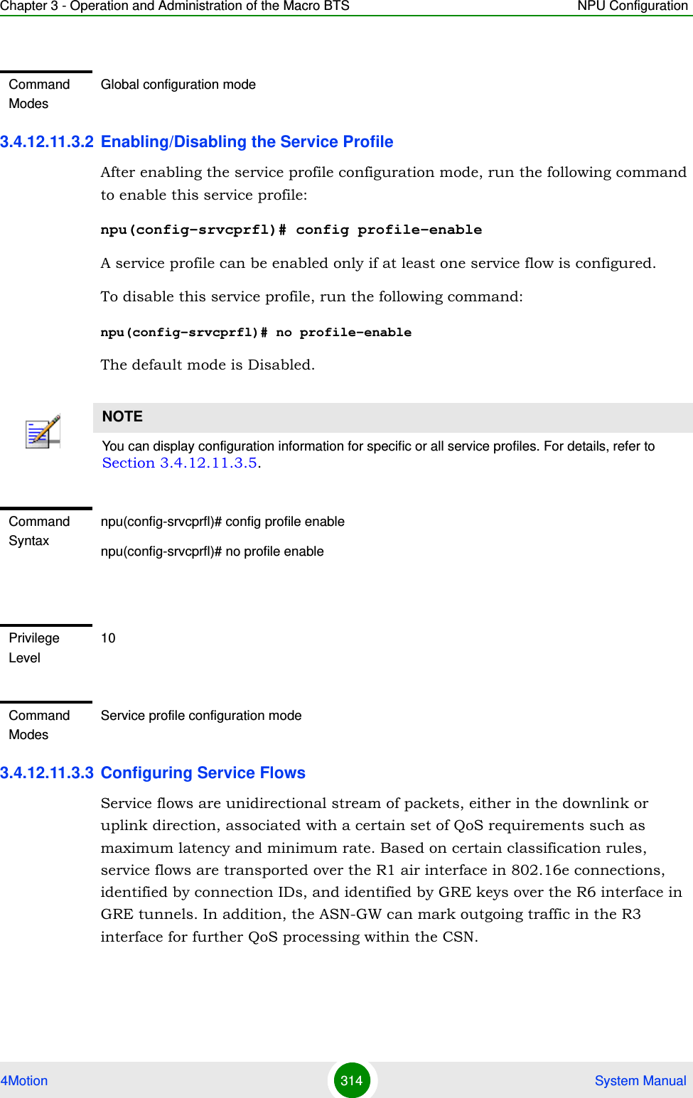
![Chapter 3 - Operation and Administration of the Macro BTS NPU Configuration4Motion 315 System ManualThe system supports two types of service flows according to the convergence sublayer (CS) type: IP CS and VLAN CS. An IP CS service flow can be associated only with an IP service group. A VLAN CS service flow can be associated only with a VPWS (Transparent/QinQ/Mapped) service group. Typically VLAN CS service flows should be managed (created/modified/deleted) only by the AAA server. However, to support special needs, it is possible to define VLAN CS service flows for the Default Service Profile.Up to 12 Service Flows can be defined for each Service Profile.1Enable the service flow configuration mode (refer to Section 3.4.12.11.3.3.1)2You can now execute any of the following tasks:»Configure the parameters for this service flow (refer to Section 3.4.12.11.3.3.2)»Restore the default parameters for this service flow (refer to Section 3.4.12.11.3.3.3)»Configure uplink/downlink classification rule names (refer to Section 3.4.12.11.3.3.4)3Terminate the service flow configuration mode (refer to Section 3.4.12.11.3.3.6)You can, at any time delete an existing service flow (refer to Section 3.4.12.11.3.3.7). 3.4.12.11.3.3.1Enabling the Service Flow Configuration Mode\ Creating a New Service FlowTo configure the parameters for a service flow, first enable the service flow configuration mode. Run the following command to enable the service flow configuration mode. You can also use this command to create a new service flow.npu(config-srvcprfl)# flow [<flow-id (1-255)] [grp-alias <srvc-grp-alias>] [if-alias <string>] [mcast-sfid <integer(0-65535)> {[mcastipv4add <string(15)>]}] [<string>]After enabling the service profile configuration mode, execute the following tasks to configure service flows within this service profile:](https://usermanual.wiki/Alvarion-Technologies/MICRO-25.Manual-p3/User-Guide-1329244-Page-66.png)
![Chapter 3 - Operation and Administration of the Macro BTS NPU Configuration4Motion 316 System ManualIf you use this command to create a new service flow, the configuration mode for this service flow is automatically enabled, after which you can execute any of the following tasks:Configure the parameters for this service flow (refer to Section 3.4.12.11.3.3.2)Restore the default parameters for this service flow (refer to Section 3.4.12.11.3.3.3)Configure uplink/downlink classification rule names (refer to Section 3.4.12.11.3.3.4)After you have executed these tasks, you can terminate the service flow configuration mode, and return to the service profile configuration mode (refer to Section 3.4.12.11.3.3.6).NOTEThe mcast-sfid and mcastipv4add parameter are for future use with a DGW profile (not supported in the current release). Do not use these parameters. In the following sections these parameters will be ignored.Command Syntaxnpu(config-srvcprfl)#flow [<flow-id (1-255)] [grp-alias <srvc-grp-alias>] [if-alias <string>]Privilege Level10Syntax Description Parameter Description Presence Default ValuePossible Valuesflow [<flow-id (1-255)]Denotes the flow ID of the service flow for which the service flow configuration mode is to be enabled. If you are creating a new service flow, specify the service flow ID of the new service flow. The configuration mode is automatically enabled for the new service flow. Mandatory N/A 1-255](https://usermanual.wiki/Alvarion-Technologies/MICRO-25.Manual-p3/User-Guide-1329244-Page-67.png)
![Chapter 3 - Operation and Administration of the Macro BTS NPU Configuration4Motion 317 System Manual3.4.12.11.3.3.2Specifying Service Flow Configuration ParametersAfter enabling the service flow configuration mode, run the following command to configure the parameters for this service flow:npu(config-srvcprfl-flow)# config ([flow-type <type (1)>] [cs-type <type (1 | 4)>] [media-type <string>] [uldatadlvry-type <type(0<UGS> | 1<RTVR> | 2<NRTVR> | 3<BE> | 4<ERTVR> | 255<ANY>)>] [ulqos-maxsustainedrate <value(10000-40000000)>] [ulqos-trafficpriority <value(0-7)>] [dldatadlvry-type <type(0<UGS> | 1<RTVR> | 2<NRTVR> | 3<BE> | 4<ERTVR> | 255<ANY>)>] [dlqos-maxsustainedrate <value(10000-40000000)>] [dlqos-trafficpriority <value(0-7)>] [ul-rsrv-rate-min <integer(0-40000000)>] [ul-latency-max <integer>] [ul-tolerated-jitter <integer)>] [ul-unsol-intrvl <integer(0-65535)>] [dl-rsrv-rate-min <integer(0-40000000)>] [dl-latency-max <integer>] [dl-tolerated-jitter <integer>])[grp-alias <srvc-grp-alias>]Indicates the Reference Name for an existing service group to be used by the service flow. VPWS Service Groups are applicable only for VLAN CS Service Flows of the Default Service Profile.Mandatory when creating a new flowN/A An existing Service Group Alias.[if-alias <string>] Indicates the Reference Name for an existing QinQ service interface.Applicable only if the assigned Service Group is of type VPWS-QinQ (in a VLANCS Service Flow of the Default Service Profile).Mandatory when creating a new flow, only if the type of the specified grp-alias is VPWS-QinQ.N/A An existing QinQ Service Interface.Command ModesService profile configuration modeIMPORTANTAn error may occur if you provide an invalid value for any of these parameters. Refer the syntax description for more information about the appropriate values and format for configuring these parameters.](https://usermanual.wiki/Alvarion-Technologies/MICRO-25.Manual-p3/User-Guide-1329244-Page-68.png)
![Chapter 3 - Operation and Administration of the Macro BTS NPU Configuration4Motion 318 System ManualCommand Syntaxnpu(config-srvcprfl-flow)# config ([flow-type <type (1)>] [cs-type <type (1 | 4)>] [media-type <string>] [uldatadlvry-type <type(0<UGS> | 1<RTVR> | 2<NRTVR> | 3<BE> | 4<ERTVR> | 255<ANY>)>] [ulqos-maxsustainedrate <value(10000-40000000)>] [ulqos-trafficpriority <value(0-7)>] [dldatadlvry-type <type(0<UGS> | 1<RTVR> | 2<NRTVR> | 3<BE> | 4<ERTVR> | 255<ANY>)>] [dlqos-maxsustainedrate <value(10000-40000000)>] [dlqos-trafficpriority <value(0-7)>] [ul-rsrv-rate-min <integer(0-40000000)>] [ul-latency-max <integer>] [ul-tolerated-jitter <integer)>] [ul-unsol-intrvl <integer(0-65535)>] [dl-rsrv-rate-min <integer(0-40000000)>] [dl-latency-max <integer>] [dl-tolerated-jitter <integer>])Privilege Level10Syntax Description Parameter Description Presence Default ValuePossible Values[flow-type <type (1)>] Denotes the type of flow, that is, bi-directional (1) or multicast (2).multicast (2) is not supported in current release.Optional 1 1: Indicates bi-directional[cs-type <type (1 | 4)>]Convergence Sublayer Type. This parameter is applied to both UL and DL Service Flows.Must match the type of service group referenced by ServiceGrpAlias during creation of the flow: IPv4CS should be selected if the assigned Service Group is of type IP. VLANCS should be selected if the assigned Service Group is of type VPWS.Optional 1 (IPv4CS)1: IPv4CS 4: VLANCS [media-type <string>]Describes the type of media carried by the service flow.Optional Null String, up to 32 characters](https://usermanual.wiki/Alvarion-Technologies/MICRO-25.Manual-p3/User-Guide-1329244-Page-69.png)
![Chapter 3 - Operation and Administration of the Macro BTS NPU Configuration4Motion 319 System Manual[uldatadlvry-type <type(0<UGS> | 1<RTVR> | 2<NRTVR> | 3<BE> | 4<ERTVR> | 255<ANY>)>]Denotes the data delivery type for uplink traffic carried by the service flow. Optional 3 (BE) 0-4 or 255 for ANY.[ulqos-maxsustainedrate <value(10000-40000000)>]Denotes the maximum sustained traffic rate, in bps, for uplink traffic carried by the service flow.Although available for all service flows, applicable only for service flows with the appropriate uplink data delivery type (NRTVR, RTVR, BE, ERTVR, ANY)Optional 250000 10000-40000000 bps[ulqos-trafficpriority <value(0-7)>]Denotes the traffic priority to be applied to the uplink traffic carried by the service flow.Although available for all service flows, not applicable for service flows with UGS uplink data delivery type.Optional 0 0-7, where 0 is lowest and 7 is highest[dldatadlvry-type <type(0<UGS> | 1<RTVR> | 2<NRTVR> | 3<BE> | 4<ERTVR> | 255<ANY>)>]Denotes the data delivery type for the downlink traffic carried by the service flow. Optional 3 (BE) 0 (UGS)1 (RTVR)2 (NRTVR)3 (BE)4 (ERTVR)255 (ANY)[dlqos-maxsustainedrate <value(10000-40000000)>]Denotes the maximum sustained traffic rate, in bps, for the downlink traffic carried by the service flow.Although available for all service flows, applicable only for service flows with the appropriate downlink data delivery type (NRTVR, RTVR, BE, ERTVR, ANY)Optional 250000 10000-40000000 bps](https://usermanual.wiki/Alvarion-Technologies/MICRO-25.Manual-p3/User-Guide-1329244-Page-70.png)
![Chapter 3 - Operation and Administration of the Macro BTS NPU Configuration4Motion 320 System Manual[dlqos-trafficpriority <value(0-7)>]Denotes the traffic priority to be applied to the downlink traffic carried by the service flow.Although available for all service flows, not applicable for service flows with UGS uplink data delivery type.Optional 0 0-7, where 7 is highest[ul-rsrv-rate-min <integer(0-40000000)>]the minimum rate in bps reserved for this uplink service flow.Although available for all service flows, applicable only for service flows with the appropriate uplink data delivery type (UGS, NRTVR, RTVR, ERTVR).For NRTVER, RTVR and ERTVR-cannot be higher than ulqos-maxsustainedrate.Optional 250000 0- 40000000[ul-latency-max <integer>]The maximum latency in ms allowed in the uplink.Although available for all service flows, applicable only for service flows with the appropriate uplink data delivery type (UGS, RTVR, ERTVR).If uplink data delivery type is ERTVR or UGS, the default value should be 90ms.Optional 500 0- 4294967295[ul-tolerated-jitter <integer)>]the maximum delay variation (jitter) in milliseconds for this uplink service flow.Although available for all service flows, applicable only for service flows with the appropriate uplink data delivery type (UGS, ERTVR)Optional 0 0- 4294967295](https://usermanual.wiki/Alvarion-Technologies/MICRO-25.Manual-p3/User-Guide-1329244-Page-71.png)
![Chapter 3 - Operation and Administration of the Macro BTS NPU Configuration4Motion 321 System Manual[ul-unsol-intrvl <integer(0-65535)>]The nominal interval in ms between successive data grant opportunities for this uplink service flow.Although available for all service flows, applicable only for service flows with the appropriate uplink data delivery type (UGS, ERTVR).Must be lower than ul-latency-max.Optional 20 0-65535[dl-rsrv-rate-min <integer(0-40000000)>]the minimum rate in bps reserved for this downlink service flow.Although available for all service flows, applicable only for service flows with the appropriate downlink data delivery type (UGS, NRTVR, RTVR, ERTVR)For NRTVER, RTVR and ERTVR-cannot be higher than dlqos-maxsustainedrate.Optional 250000 0- 40000000[dl-latency-max <integer>]The maximum latency in ms allowed in the downlink.Although available for all service flows, applicable only for service flows with the appropriate downlink data delivery type (UGS, RTVR, ERTVR).If uplink data delivery type is ERTVR or UGS, the default value should be 90ms.Optional 500 0- 4294967295[dl-tolerated-jitter <integer)>]the maximum delay variation (jitter) in milliseconds for this downlink service flow.Although available for all service flows, applicable only for service flows with the appropriate downlink data delivery type (UGS, ERTVR)Optional 0 0- 4294967295](https://usermanual.wiki/Alvarion-Technologies/MICRO-25.Manual-p3/User-Guide-1329244-Page-72.png)
![Chapter 3 - Operation and Administration of the Macro BTS NPU Configuration4Motion 322 System Manual3.4.12.11.3.3.3Restoring the Default Service Flow Configuration ParametersRun the following command to restore the default values of one or several parameters for this service flow:npu(config-srvcprfl-flow)# no [cs-type] [media-type] [uldatadlvry-type] [ulqos-maxsustainedrate] [ulqos-trafficpriority] [dldatadlvry-type] [dlqos-maxsustainedrate] [dlqos-trafficpriority][ul-rsrv-rate-min] [ul-latency-max] [ul-tolerated-jitter] [ul-unsol-intrvl] [dl-rsrv-rate-min] [dl-latency-max] [dl-tolerated-jitter]Do not specify any parameter to restore all parameters to their default values.3.4.12.11.3.3.4Configuring Uplink/Downlink Classification Rule NamesAfter enabling the service flow configuration mode, run the following commands to configure up to a maximum of 6 uplink and 6 downlink classification rules:npu(config-srvcprfl-flow)# ulclsf-rulename <num_of_rule_names (1-6)> <rulename> [<rulename>] [...]npu(config-srvcprfl-flow)# dlclsf-rulename <num_of_rule_names (1-6)> <rulename> [<rulename>] [...]Command ModesService profile-service flow configuration modeNOTERefer to Section 3.4.12.11.3.3.2 for a description and default values of these parameters. Command Syntaxnpu(config-srvcprfl-flow)# no [cs-type] [media-type] [uldatadlvry-type] [ulqos-maxsustainedrate] [ulqos-trafficpriority] [dldatadlvry-type] [dlqos-maxsustainedrate] [dlqos-trafficpriority][ul-rsrv-rate-min] [ul-latency-max] [ul-tolerated-jitter] [ul-unsol-intrvl] [dl-rsrv-rate-min] [dl-latency-max] [dl-tolerated-jitter]Privilege Level10Command ModesService profile-service flow configuration mode](https://usermanual.wiki/Alvarion-Technologies/MICRO-25.Manual-p3/User-Guide-1329244-Page-73.png)
![Chapter 3 - Operation and Administration of the Macro BTS NPU Configuration4Motion 323 System ManualAfter you have executed these tasks, you can terminate the service flow configuration mode, and return to the service profile configuration mode (Section 3.4.12.11.3.3.6). For more information about configuring classification rules, refer “Configuring Classification Rules” on page 330.IMPORTANT.If no classifier is associated with the service flow for one or both directions, it means any traffic.Command Syntaxnpu(config-srvcprfl-flow)# ulclsf-rulename <num_of_rule_names (1-6)> <rulename> [<rulename>] [...]npu(config-srvcprfl-flow)# dlclsf-rulename <num_of_rule_names (1-6)> <rulename> [<rulename>] [...]Privilege Level10Syntax Description Parameter Description Presence Default ValuePossible Values<num_of_rule_names (1-6)>Indicates the number of uplink/downlink classification rules to be createdMandatory N/A 1-6](https://usermanual.wiki/Alvarion-Technologies/MICRO-25.Manual-p3/User-Guide-1329244-Page-74.png)
![Chapter 3 - Operation and Administration of the Macro BTS NPU Configuration4Motion 324 System Manual3.4.12.11.3.3.5Deleting Uplink/Downlink Classification Rule NamesAfter enabling the service flow configuration mode, run the following commands to delete uplink/downlink classification rules:npu(config-srvcprfl-flow)# no ulclsf-rulename [<num_of_rulenames (1-6)> <rulename> [<rulename>] ...]npu(config-srvcprfl-flow)# no dlclsf-rulename [<num_of_rulenames (1-6)> <rulename> [<rulename>] ...]After you have executed these commands, you can terminate the service flow configuration mode, and return to the service profile configuration mode (refer to Section 3.4.12.11.3.3.6)<rulename> Indicates the name of the uplink/downlink classification rule to be linked to this service flow. Use the classification rule name to reference the appropriate classification rule.For VLANCS service flows the linked uplink and downlink classification rules should be the same. This is because the VLANCS classification rules define the CVID (Customer VLAN ID), that should be the same for uplink and downlink flows.The number of rule name entries must match the number defined in num_of_rule_names.For more information about creating classification rules, refer to Section 3.4.12.11.4.1.Mandatory N/A Valid classification rule nameCommand ModesService profile-service flow configuration mode](https://usermanual.wiki/Alvarion-Technologies/MICRO-25.Manual-p3/User-Guide-1329244-Page-75.png)
![Chapter 3 - Operation and Administration of the Macro BTS NPU Configuration4Motion 325 System Manual3.4.12.11.3.3.6Terminating the Service Flow Configuration ModeRun the following command to terminate the service flow configuration mode:npu(config-srvcprfl-flow)# exitCommand Syntaxnpu(config-srvcprfl-flow)# no ulclsf-rulename [<num_of_rulenames (1-6)> <rulename> [<rulename>] ...]npu(config-srvcprfl-flow)# no dlclsf-rulename [<num_of_rulenames (1-6)> <rulename> [<rulename>] ...]Privilege Level10Syntax Description Parameter Description Presence Default ValuePossible Values[<num_of_rulenames (1-6)>Indicates the number of uplink/downlink classification rules to be deleted.Mandatory N/A 1-6<rulename> Indicates the name of the uplink/downlink classification rule to be deleted from to this service flow. Use the classification rule name to reference the appropriate classification rule.The number of rule name entries must match the number defined in num_of_rule_names.Mandatory N/A Valid classification rule nameCommand ModesService profile-service flow configuration modeCommand Syntaxnpu(config-srvcprfl-flow)# exit](https://usermanual.wiki/Alvarion-Technologies/MICRO-25.Manual-p3/User-Guide-1329244-Page-76.png)
![Chapter 3 - Operation and Administration of the Macro BTS NPU Configuration4Motion 326 System Manual3.4.12.11.3.3.7Deleting Service FlowsYou can, at any time, run the following command to delete one or all service flows:npu(config-srvcprfl)# no flow [<flow-id>]3.4.12.11.3.4 Terminating the Service Profile Configuration ModeRun the following command to terminate the service profile configuration mode:Privilege Level10Command ModesService profile-service flow configuration modeCAUTIONSpecify the flow ID if you want to delete a specific service flow. Otherwise all the configured service flows are deleted.Command Syntaxnpu(config-srvcprfl)# no flow [<flow-id>]Privilege Level10Command Syntaxnpu(config-srvcprfl)# no flow [<flow-id>]Syntax Description Parameter Description Presence Default ValuePossible Values[<flow-id>] Denotes the flow ID of the service flow to be deleted. If you do not specify a value for this parameter, all the service flows are deleted.Optional N/A 0-255 Command ModesService profile configuration mode](https://usermanual.wiki/Alvarion-Technologies/MICRO-25.Manual-p3/User-Guide-1329244-Page-77.png)
![Chapter 3 - Operation and Administration of the Macro BTS NPU Configuration4Motion 327 System Manualnpu(config-srvcprfl)# exit3.4.12.11.3.5 Displaying Configuration Information for Service Profiles To display all or specific service profiles, run the following command:npu# show srvc-profile [<profile-name>]Specify the profile name if you want to display configuration information for a particular service profile. Do not specify a value for this parameter if you want to view configuration information for all service profile.Command Syntaxnpu(config-srvcprfl)# exitPrivilege Level10Command ModesService profile configuration modeIMPORTANTAn error may occur if you provide an invalid service profile name. Refer the syntax description for more information about the appropriate values and format for configuring this parameter.Command Syntaxnpu# show srvc-profile [<profile-name>]Privilege Level1](https://usermanual.wiki/Alvarion-Technologies/MICRO-25.Manual-p3/User-Guide-1329244-Page-78.png)
![Chapter 3 - Operation and Administration of the Macro BTS NPU Configuration4Motion 328 System ManualSyntax Description Parameter Description Presence Default ValuePossible Values[<profile-name>] Indicates the name of the service profile for which configuration information is to be displayed. If you do not specify a value for this parameter, configuration information is displayed for all service profiles.Optional N/A String](https://usermanual.wiki/Alvarion-Technologies/MICRO-25.Manual-p3/User-Guide-1329244-Page-79.png)
![Chapter 3 - Operation and Administration of the Macro BTS NPU Configuration4Motion 329 System Manual3.4.12.11.3.6 Deleting Service ProfilesRun the following command to delete one or all service profiles:npu(config)# no srvc-profile [<profile-name>]Display FormatSrvc Profile <value>status <value>flow-id <value>flow-type <value>srvc-grp <value>Service-If <value or null>CS-type <value>Media-Type <value>UL-flowDataDeliveryType <value>UL-flowQosMaxSustainedRate <value>UL-flowQosTrafficPrority <value>DL-flowDataDeliveryType <value>DL-flowQosMaxSustainedRate <value>DL-flowQosTrafficPrority <value>UL-MinReservedTrafficRate <value>UL-MaxLatencey <value>UL-ToleratedJitter <value>UL-UnsolicitedGrantInterval <value>DL-MinReservedTrafficRate <value>DL-MaxLatencey <value>DL-ToleratedJitter <value>UL-Rulenames :<value>, <value>.....DL-Rulenames :<value>, <value>....flow-id <value>............ Command ModesGlobal configuration mode](https://usermanual.wiki/Alvarion-Technologies/MICRO-25.Manual-p3/User-Guide-1329244-Page-80.png)
![Chapter 3 - Operation and Administration of the Macro BTS NPU Configuration4Motion 330 System Manual3.4.12.11.4 Configuring Classification RulesClassification rules are user-configurable rules that are used to classify packets transmitted on the bearer plane. You can associate one or more classification rules with a particular service profile (For details, refer to Section 3.4.12.11.3.3.4). You can define an L3 classification rule with respect to the following criteria:IP ToS/DSCPIP protocol (such as UDP or TCP)IP source address (an address mask can be used to define a range of addresses or subnet)NOTEThe Default Service Profile cannot be deleted.CAUTIONSpecify the profile name if you want to delete a specific service profile. Otherwise all the configured service profiles (excluding the Default Service Profile) are deleted.Command Syntaxnpu(config)# no srvc-profile [<profile-name>]Privilege Level10Syntax Description Parameter Description Presence Default ValuePossible Values[<profile-name>] Denotes the name of the service profile you want to delete. Specify this parameter only if you want to delete a specific service profile.Optional N/A StringCommand ModesGlobal configuration mode](https://usermanual.wiki/Alvarion-Technologies/MICRO-25.Manual-p3/User-Guide-1329244-Page-81.png)
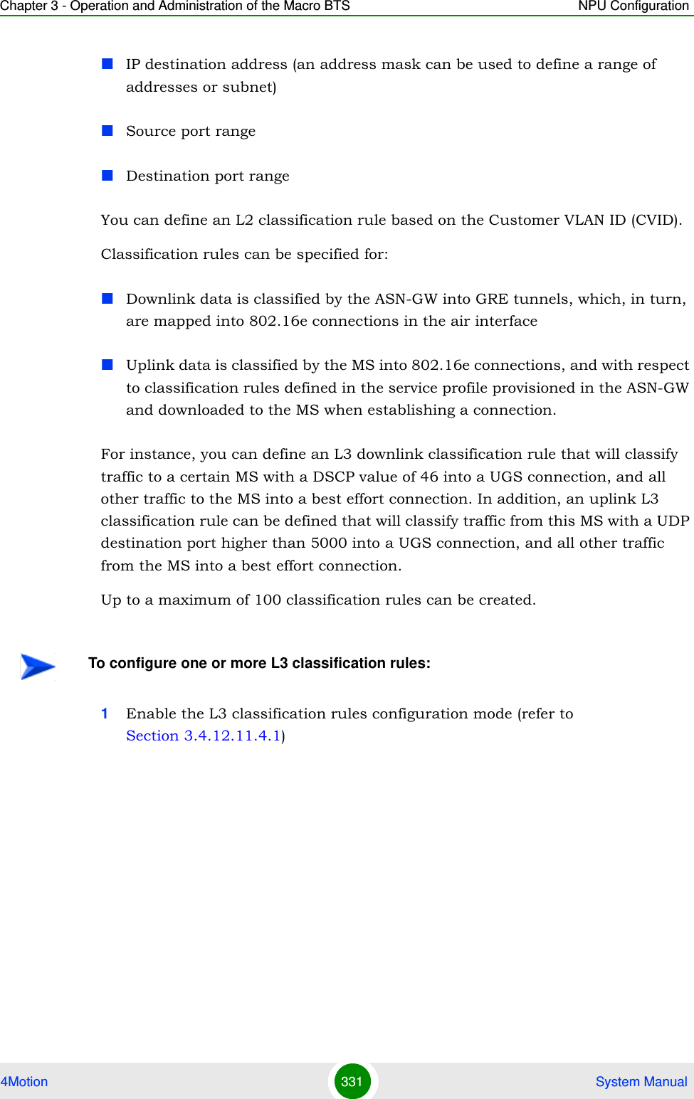
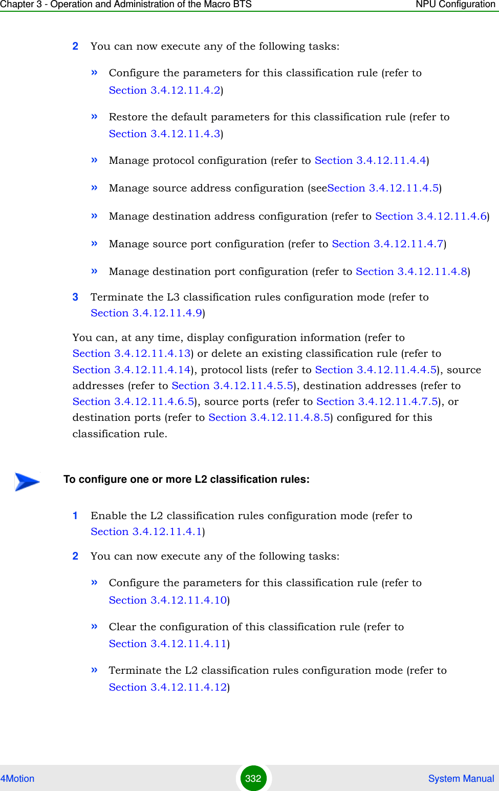
![Chapter 3 - Operation and Administration of the Macro BTS NPU Configuration4Motion 333 System ManualYou can, at any time, display configuration information (refer to Section 3.4.12.11.4.13) or delete an existing classification rule (refer to Section 3.4.12.11.4.14).3.4.12.11.4.1 Enabling the Classification Rule Configuration Mode\ Creating a New Classification RuleTo configure the parameters for a classification rule, first enable the classification rule configuration mode. Run the following command to enable the classification rule configuration mode. You can also use this command to create a new classification rule.npu(config)# clsf-rule <rulename> [clsfRuleType {L2 | L3}]If you use this command to create a new classification rule, the configuration mode for this rule is automatically enabled.After enabling the classification rule configuration mode for an L3 rule you can execute any of the following tasks:Configure the parameters for this classification rule (refer to Section 3.4.12.11.4.2).Restore the default parameters for this classification rule (refer to Section 3.4.12.11.4.3)Manage protocol configuration (refer to Section 3.4.12.11.4.4)Manage source address configuration (refer to Section 3.4.12.11.4.5)Manage destination address configuration (refer to Section 3.4.12.11.4.6)Manage source port configuration (refer to Section 3.4.12.11.4.7)Manage destination port configuration (refer to Section 3.4.12.11.4.8)After you have executed these tasks, you can terminate the classification rules configuration mode (refer to Section 3.4.12.11.4.9).After enabling the classification rule configuration mode for an L2 rule you can execute any of the following tasks:Configure the parameters for this classification rule (refer to Section 3.4.12.11.4.10).](https://usermanual.wiki/Alvarion-Technologies/MICRO-25.Manual-p3/User-Guide-1329244-Page-84.png)
![Chapter 3 - Operation and Administration of the Macro BTS NPU Configuration4Motion 334 System ManualClear the current configuration of this classification rule (refer to Section 3.4.12.11.4.11)After you have executed these tasks, you can terminate the classification rules configuration mode (refer to Section 3.4.12.11.4.12).3.4.12.11.4.2 Specifying Configuration Parameters for the L3 Classification RuleAfter enabling the classification rules configuration mode for an L3 classification rule, run the following command to configure the parameters for this classification rule:npu(config-clsfrule)# config [priority <priority(0-255)>] [phs-rulename <rulename>] [iptos-low <value(0-63)>] [iptos-high <value(0-63)>] [iptos-mask <value(0-63)>] [iptos-enable]Command Syntaxnpu(config)# clsf-rule <rulename> [clsfRuleType {L2 | L3}]Privilege Level10Syntax Description Parameter Description Presence Default ValuePossible Values<rulename> Denotes the name of the classification rule. Mandatory N/A String (1 to 30 characters)[clsfRuleType {L2 | L3}]The type of classifier: L2 or L3.Optional when creating a new rule.L3 L2L3Command ModesGlobal configuration modeNOTEYou can display configuration information for specific or all classification rules. For details, refer to Section 3.4.12.11.4.13.](https://usermanual.wiki/Alvarion-Technologies/MICRO-25.Manual-p3/User-Guide-1329244-Page-85.png)
![Chapter 3 - Operation and Administration of the Macro BTS NPU Configuration4Motion 335 System ManualCommand Syntaxnpu(config-clsfrule)# config [priority <priority(0-255)>] [phs-rulename <rulename>] [iptos-low <value(0-63)>] [iptos-high <value(0-63)>] [iptos-mask <value(0-63)>] [iptos-enable]Privilege Level10Syntax Description Parameter Description Presence Default ValuePossible Values [priority <priority(0-255)>] Denotes the priority level to be assigned to the classification rule.Optional 0 0-255[phs-rulename <rulename>] Indicates the Packet Header Suppression (PHS) rule name to be associated with the classification rule. Specify the PHS rulename if you want to perform PHS for this flow. For more information about configuring PHS rules, refer Section 3.4.12.12.Optional None StringAn existing PHS rule name.[iptos-low <value(0-63)>] Denotes the value of the lowest IP TOS field to define the lowest value where the range can begin.Cannot be higher than iptos-high.Can be modified only when IP TOS classification is disabled (see iptos-enable below). If set to a value higher than iptos-high, IP TOS classification cannot be enabled.Optional 0 0-63](https://usermanual.wiki/Alvarion-Technologies/MICRO-25.Manual-p3/User-Guide-1329244-Page-86.png)
![Chapter 3 - Operation and Administration of the Macro BTS NPU Configuration4Motion 336 System Manual3.4.12.11.4.3 Restoring the Default Parameters for the L3 Classification RuleRun the following command to restore the default configuration for this classification rule.npu(config-clsfrule)# no [priority] [iptos-low] [iptos-high] [iptos-mask] [iptos-enable][phs-rulename][iptos-high <value(0-63)>] Denotes the value of highest IP TOS field to define the highest value where the range can end.Cannot be lower than iptos-low.Can be modified only when IP TOS classification is disabled (see iptos-enable below). If set to a value lower than iptos-low, IP TOS classification cannot be enabled.Optional 0 0-63[iptos-mask <value(0-63)>] Denotes the mask for IP TOS value.This mask is applied to the TOS field received in the IP header to be matched within the TOS range configured.Optional 0 0-63[iptos-enable] Indicates whether the use of TOS-based classification is to be enabled.Optional By default, the use of TOS-based classification is disabled.The presence/absence of this flag indicates that the use of TOS-based classification should be enabled/disabled. Command ModesL3 Classification rules configuration modeNOTERefer to Section 3.4.12.11.4.3 for a description and default values of these parameters.](https://usermanual.wiki/Alvarion-Technologies/MICRO-25.Manual-p3/User-Guide-1329244-Page-87.png)
![Chapter 3 - Operation and Administration of the Macro BTS NPU Configuration4Motion 337 System Manual3.4.12.11.4.4 Managing IP Protocol Configuration for the L3 Classification RuleL3 classification rules can classify the packet, based on the value of IP protocol field. You can configure the value of IP protocol for a given classification rule.1Enable the IP protocol configuration mode (refer to Section 3.4.12.11.4.4.1)2Enable/disable IP protocol classification (refer to Section 3.4.12.11.4.4.2 anReclassifiedSection 3.4.12.11.4.4.3)3Terminate the protocol configuration mode (refer to Section 3.4.12.11.4.4.4)In addition, you can, at any time, delete an existing IP protocol classifier (refer to Section 3.4.12.11.4.4.5). The following example illustrates the sequence of commands for enabling the IP protocol configuration mode, enabling IP protocol 100, and then terminating the protocol lists configuration mode:npu(config-clsfrule)# ip-protocolnpu(config-clsfrule-protocol)# protocol-enable 1 100npu(config-clsfrule-protocol)# exit3.4.12.11.4.4.1Enabling the IP Protocol Configuration ModeRun the following command to enable the IP protocol configuration mode. npu(config-clsfrule)# ip-protocolYou can now enable or disable the IP protocol (refer to Section 3.4.12.11.4.4.2 and Section 3.4.12.11.4.4.3).Command Syntaxnpu(config-clsfrule)# no [priority] [iptos-low] [iptos-high] [iptos-mask] [iptos-enable] [phs-rulename]Privilege Level10Command ModesL3 Classification rules configuration modeTo configure IP protocol classifier:](https://usermanual.wiki/Alvarion-Technologies/MICRO-25.Manual-p3/User-Guide-1329244-Page-88.png)
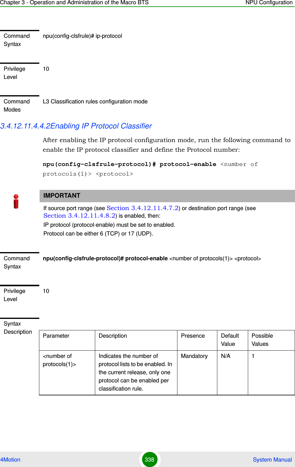
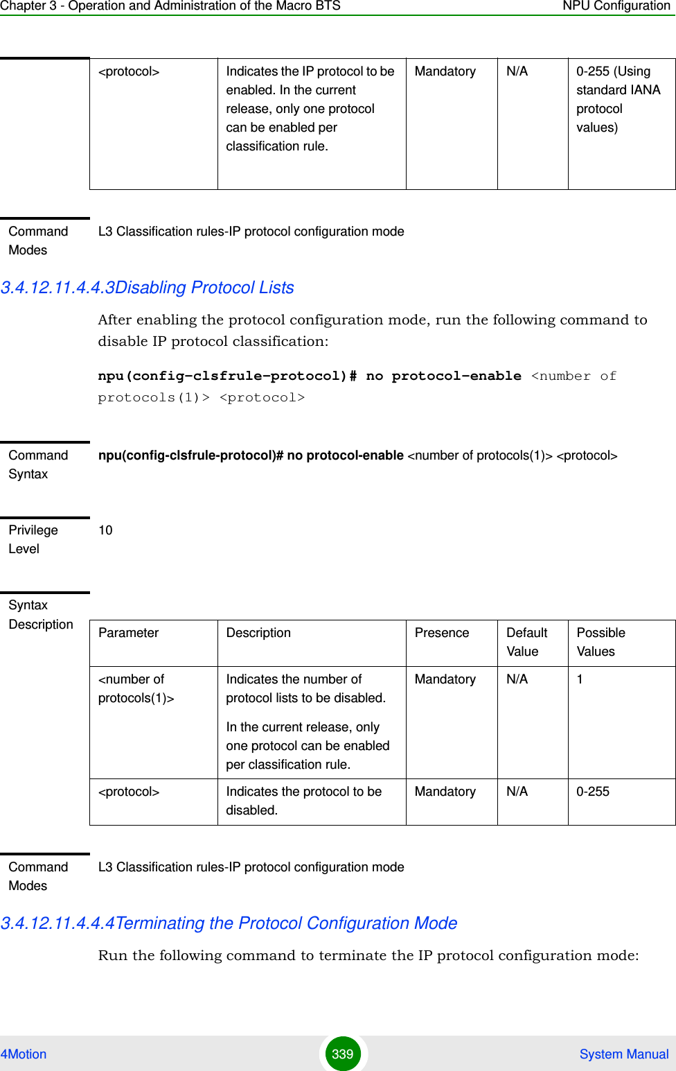
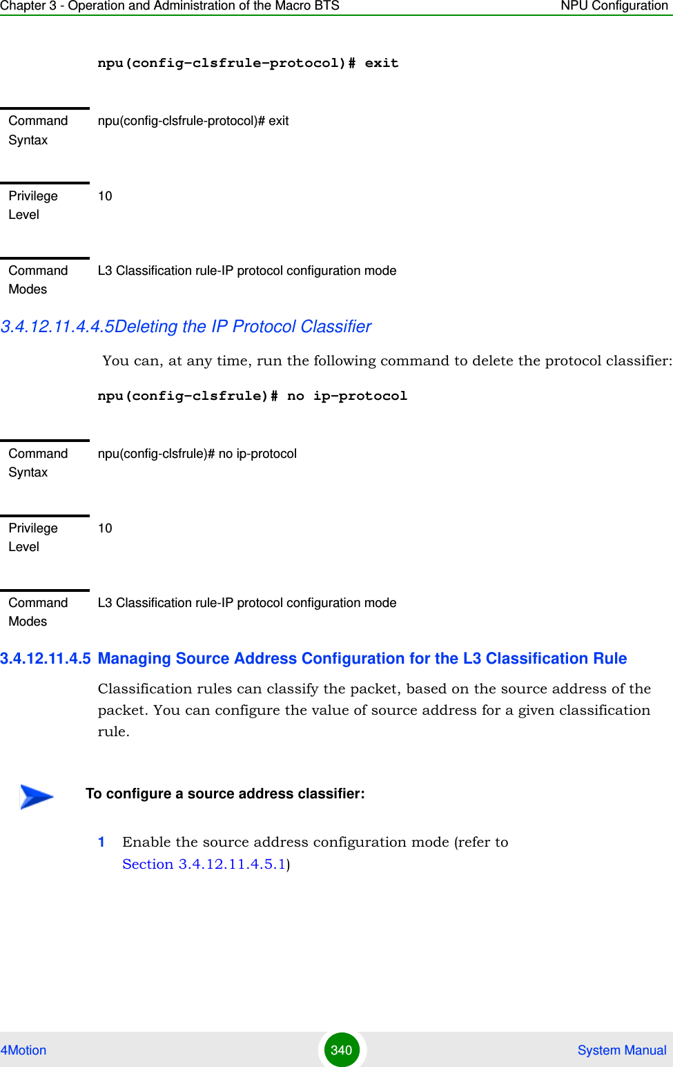
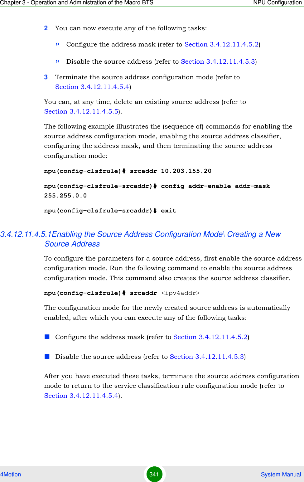
![Chapter 3 - Operation and Administration of the Macro BTS NPU Configuration4Motion 342 System Manual3.4.12.11.4.5.2Enabling the Source Address and Configuring the Address MaskAfter enabling the source address configuration mode, run the following command to enable the source address and configure the address mask for the source address. npu(config-clsfrule-srcaddr)# config [addr-enable] [addr-mask <value>]You can also run this command to enable a source address that is currently disabled. For details, refer to “Disabling the Source Address” on page 343.IMPORTANTAn error may occur if you provide an invalid source IP address. Refer the syntax description for more information about the appropriate value and format for configuring this parameter.Command Syntaxnpu(config-clsfrule)# srcaddr <ipv4addr>Syntax Description Parameter Description Presence Default ValuePossible Values<ipv4addr> Denotes the IPv4 address of the source address for which the configuration mode is to be enabled. The source address configuration mode is automatically enabled. Mandatory N/A Valid IP AddressPrivilege Level10Command ModesL3 Classification rules configuration modeIMPORTANTAn error may occur if you provide an invalid address mask for the source address. Refer the syntax description for more information about the appropriate value and format for this parameter.](https://usermanual.wiki/Alvarion-Technologies/MICRO-25.Manual-p3/User-Guide-1329244-Page-93.png)
![Chapter 3 - Operation and Administration of the Macro BTS NPU Configuration4Motion 343 System Manual3.4.12.11.4.5.3Disabling the Source AddressYou can run the following command to disable the source address that is currently enabled:npu(config-clsfrule-srcaddr)# no addr-enableCommand Syntaxnpu(config-clsfrule-srcaddr)# config [addr-enable] [addr-mask <value>]Privilege Level10Syntax Description Parameter Description Presence Default Value Possible Values[addr-enable] Indicates that the use of the associated source address is enabled for the classification rule that you are configuring. If the use of this address is disabled, the associated source address is ignored while classifying the packet. Optional By default, the use of the associated source address is disabled.The presence/absence of this flag indicates that the use of the associated source address is enabled/disabled.[addr-mask <value>]Denotes the mask field that is used to specify a range of source addresses.Optional 255.255.255.255Valid address maskCommand ModesL3 Classification rules-source address configuration modeIMPORTANTTo enable this source address, run the following command: npu(config-clsfrule-srcaddr)# config [addr-enable] [addr-mask <value>]For details, refer to “Enabling the Source Address and Configuring the Address Mask” on page 342.](https://usermanual.wiki/Alvarion-Technologies/MICRO-25.Manual-p3/User-Guide-1329244-Page-94.png)
![Chapter 3 - Operation and Administration of the Macro BTS NPU Configuration4Motion 344 System Manual3.4.12.11.4.5.4Terminating the Source Address Configuration ModeRun the following command to terminate the source address configuration mode:npu(config-clsfrule-srcaddr)# exit3.4.12.11.4.5.5Deleting Source Address You can, at any time, run the following command to delete the source address classifier:npu(config-clsfrule)# no srcaddr [<ip-Addr>]Command Syntaxnpu(config-clsfrule-srcaddr)# no addr-enablePrivilege Level10Command ModesL3 Classification rules-source address configuration modeCommand Syntaxnpu(config-clsfrule-srcaddr)# exitPrivilege Level10Command ModesL3 Classification rule-source address configuration modeCommand Syntaxnpu(config-clsfrule)# no srcaddr [<ip-Addr>]Privilege Level10](https://usermanual.wiki/Alvarion-Technologies/MICRO-25.Manual-p3/User-Guide-1329244-Page-95.png)
![Chapter 3 - Operation and Administration of the Macro BTS NPU Configuration4Motion 345 System Manual3.4.12.11.4.6 Managing Destination Address Configuration for the L3 Classification RuleClassification rules can classify the packet, based on the destination address of the packet. You can configure the value of destination address for a given classification rule.1Enable the destination address configuration mode (refer to Section 3.4.12.11.4.6.1)2You can now execute any of the following tasks:»Configure the address mask (refer to Section 3.4.12.11.4.6.2)»Disable the destination address (refer to Section 3.4.12.11.4.6.3)3Terminate the destination address configuration mode (refer to Section 3.4.12.11.4.6.4)In addition, you can, at any time, delete an existing destination address (refer to Section 3.4.12.11.4.6.5). The following example illustrates the (sequence of) commands for enabling the destination address configuration mode, enabling the destination address classifier, configuring the address mask, and then terminating the destination address configuration mode:npu(config-clsfrule)# dstaddr 10.203.155.22Syntax Description Parameter Description Presence Default ValuePossible Values[<ip-Addr>] Denotes the IPv4 address of the source address that you want to delete from a classification rule. Optional N/A Valid IP AddressCommand ModesL3 Classification rules configuration modeTo configure a destination address classifier:](https://usermanual.wiki/Alvarion-Technologies/MICRO-25.Manual-p3/User-Guide-1329244-Page-96.png)
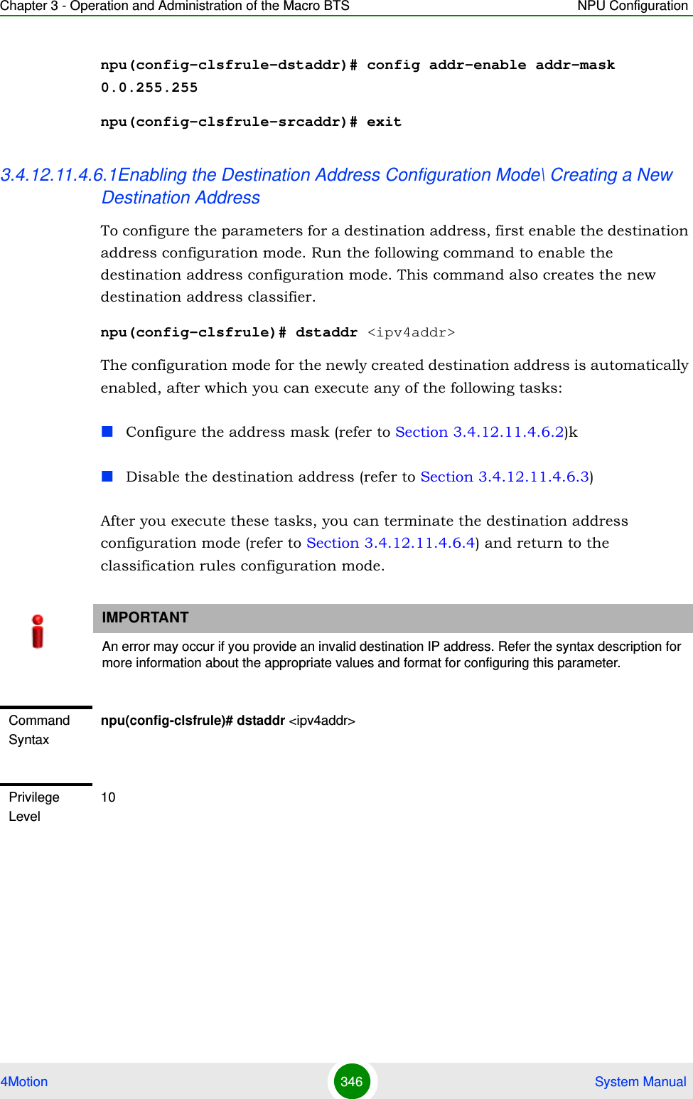
![Chapter 3 - Operation and Administration of the Macro BTS NPU Configuration4Motion 347 System Manual3.4.12.11.4.6.2Enabling the Destination Address and Configuring the Address MaskRun the following command to enable the destination address classifier and configure the address mask for the destination address. npu(config-clsfrule-dstaddr)# config [addr-enable] [addr-mask <value>]You can also run this command to enable a destination address that is currently disabled. For details, refer to “Disabling the Destination Address” on page 348.Syntax Description Parameter Description Presence Default ValuePossible Values<ipv4addr> Denotes the IPv4 address of the destination address for which the configuration mode is to be enabled. The destination address configuration mode is automatically enabled.Mandatory N/A Valid IP AddressCommand ModesL3 Classification rules configuration modeIMPORTANTAn error may occur if you provide an invalid address mask. Refer the syntax description for more information about the appropriate values and format for configuring this parameter.Command Syntaxnpu(config-clsfrule-dstaddr)# config [addr-enable] [addr-mask <value>]Privilege Level10](https://usermanual.wiki/Alvarion-Technologies/MICRO-25.Manual-p3/User-Guide-1329244-Page-98.png)
![Chapter 3 - Operation and Administration of the Macro BTS NPU Configuration4Motion 348 System Manual3.4.12.11.4.6.3Disabling the Destination AddressRun the following command to disable the destination address that is currently enabled:npu(config-clsfrule-dstaddr)# no addr-enableSyntax Description Parameter Description Presence Default Value Possible Values[addr-enable] Indicates that the use of the associated destination address is enabled for the classification rule that you are configuring. If the use of this address is disabled, the associated destination address is ignored while classifying the packet. Optional By default, the use of the associated destination address is disabled.The presence/absence of this flag indicates that the use of the associated destination address is enabled/disabled.[addr-mask <value>]Denotes the mask field that is used to specify a range of destination addresses.Optional 255.255.255.255 Valid address maskCommand ModesL3 Classification rules-destination address configuration modeCommand Syntaxnpu(config-clsfrule-dstaddr)# no addr-enablePrivilege Level10Command ModesL3 Classification rules-destination address configuration mode](https://usermanual.wiki/Alvarion-Technologies/MICRO-25.Manual-p3/User-Guide-1329244-Page-99.png)
![Chapter 3 - Operation and Administration of the Macro BTS NPU Configuration4Motion 349 System Manual3.4.12.11.4.6.4Terminating the Destination Address Configuration ModeRun the following command to terminate the destination address configuration mode:npu(config-clsfrule-dstaddr)# exit3.4.12.11.4.6.5Deleting Destination Address You can, at any time, run the following command to delete the destination address classifier:npu(config-clsfrule)# no dstaddr [<ip-Addr>]Command Syntaxnpu(config-clsfrule-dstaddr)# exitPrivilege Level10Command ModesL3 Classification rule-destination address configuration modeIMPORTANTAn error may occur if you provide an invalid IP address. Refer the syntax description for more information about the appropriate values and format for configuring this parameter.Command Syntaxnpu(config-clsfrule)# no dstaddr [<ip-Addr>]Privilege Level10Syntax Description Parameter Description Presence Default ValuePossible Values[<ip-Addr>] Denotes the IPv4 address of the destination address that you want to delete from a classification rule. Optional N/A Valid IP Address](https://usermanual.wiki/Alvarion-Technologies/MICRO-25.Manual-p3/User-Guide-1329244-Page-100.png)
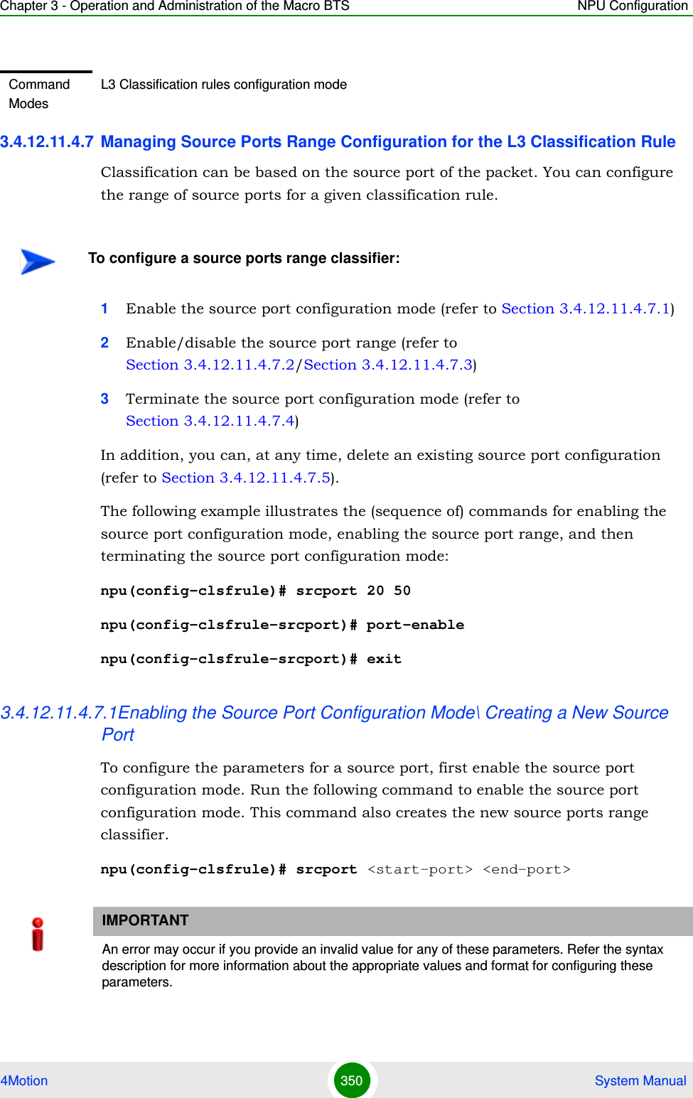
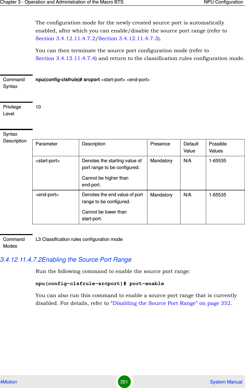
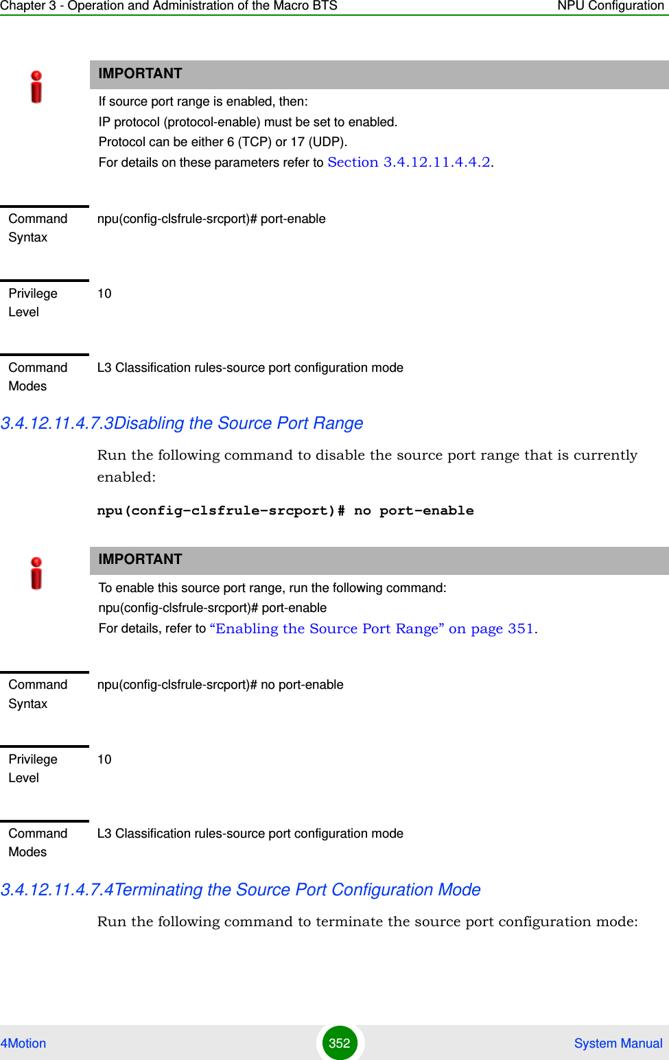
![Chapter 3 - Operation and Administration of the Macro BTS NPU Configuration4Motion 353 System Manualnpu(config-clsfrule-srcport)# exit3.4.12.11.4.7.5Deleting Source Ports Range Run the following command to delete a source ports range classifier:npu(config-clsfrule)# no srcport [<start-port> <end-port>]Command Syntaxnpu(config-clsfrule-srcport)# exitPrivilege Level10Command ModesL3 Classification rule-source port configuration modeIMPORTANTAn error may occur if you provide an invalid value for the start-port and end-port parameters. Refer the syntax description for more information about the appropriate values and format for configuring these parameters.Command Syntaxnpu(config-clsfrule)# no srcport [<start-port> <end-port>]Privilege Level10Syntax Description Parameter Description Presence Default ValuePossible Values<start-port> Denotes the starting value of port range to be deleted.Optional N/A 1-65535<end-port> Denotes the end value of port range to be deleted.Optional N/A 1-65535Command ModesL3 Classification rules configuration mode](https://usermanual.wiki/Alvarion-Technologies/MICRO-25.Manual-p3/User-Guide-1329244-Page-104.png)
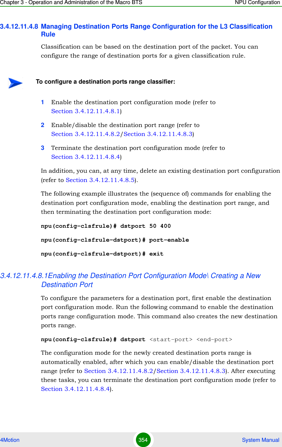
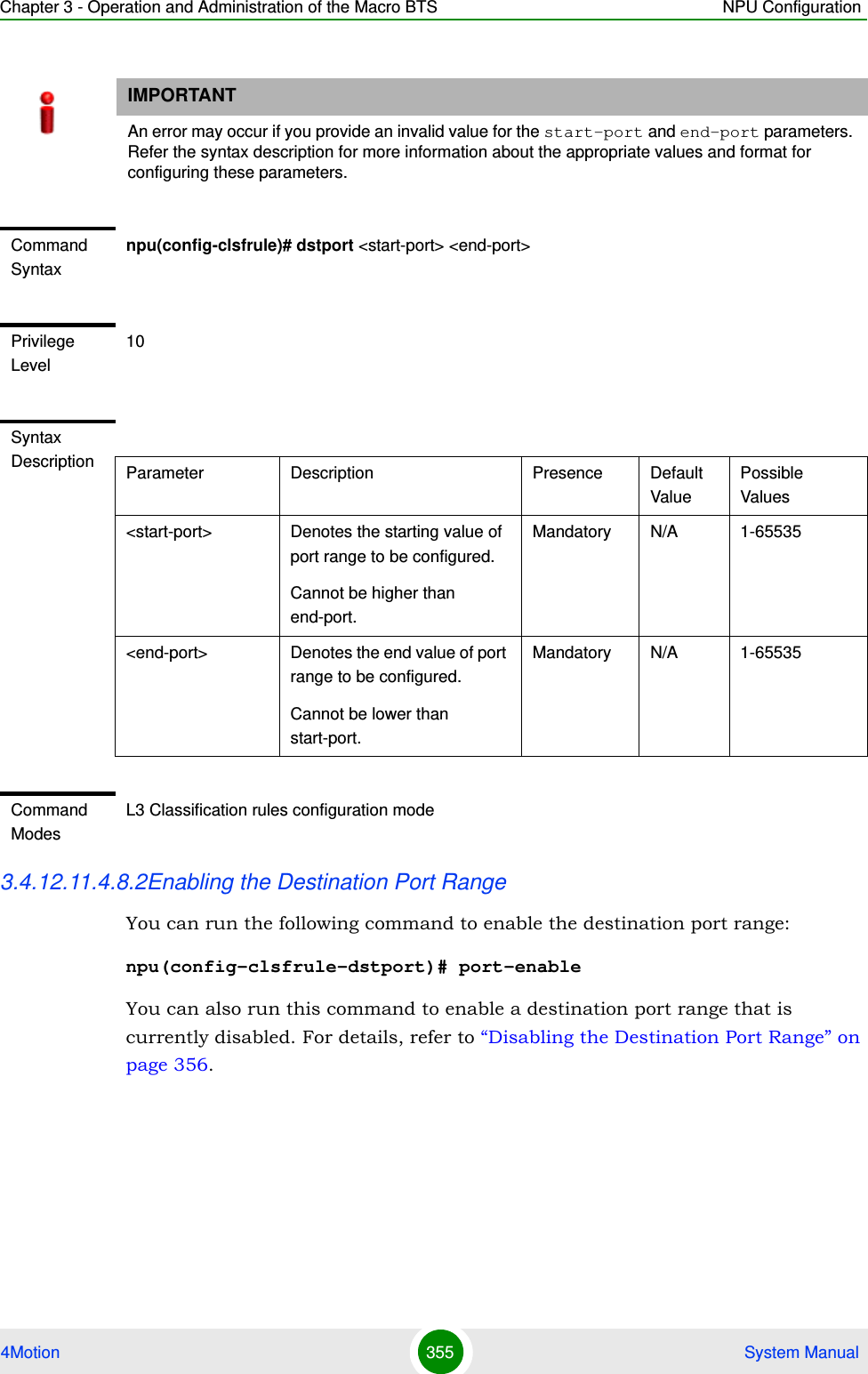
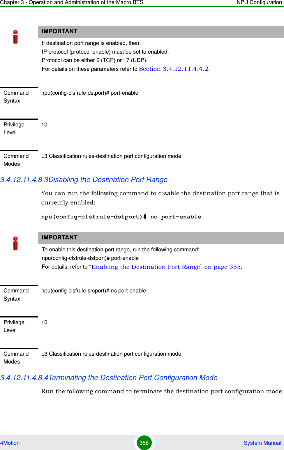
![Chapter 3 - Operation and Administration of the Macro BTS NPU Configuration4Motion 357 System Manualnpu(config-clsfrule-dstport)# exit3.4.12.11.4.8.5Deleting Destination Ports Range Run the following command to delete the destination ports range:npu(config-clsfrule)# no dstport [<start-port> <end-port>]Command Syntaxnpu(config-clsfrule-dstport)# exitPrivilege Level10Command ModesL3 Classification rule-destination port configuration modeIMPORTANTAn error may occur if you provide an invalid value for the start-port and end-port parameters. Refer the syntax description for more information about the appropriate values and format for configuring these parameters.Command Syntaxnpu(config-clsfrule)# no dstport [<start-port> <end-port>]Privilege Level10Syntax Description Parameter Description Presence Default ValuePossible Values<start-port> Denotes the starting value of port range to be deleted.Optional N/A 1-65535<end-port> Denotes the end value of port range to be deleted.Optional N/A 1-65535Command ModesL3 Classification rules configuration mode](https://usermanual.wiki/Alvarion-Technologies/MICRO-25.Manual-p3/User-Guide-1329244-Page-108.png)
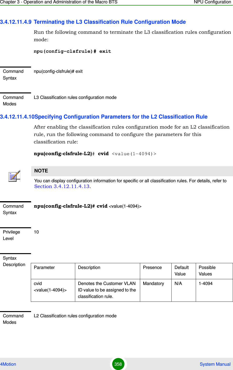
![Chapter 3 - Operation and Administration of the Macro BTS NPU Configuration4Motion 359 System Manual3.4.12.11.4.11Clearing the configuration of the L2 Classification RuleRun the following command to clear the configuration of this classification rule (removing the configured cvid):npu(config-clsfrule-L2)# no cvidAfter clearing the configuration you can define a new cvid for this classification rule.3.4.12.11.4.12Terminating the L2 Classification Rule Configuration ModeRun the following command to terminate the L2 classification rules configuration mode:npu(config-clsfrule-L2)# exit3.4.12.11.4.13Displaying Configuration Information for Classification Rules To display all or specific classification rules, run the following command:npu# show clsf-rule [<rulename>]Specify the classification rule name if you want to display configuration information for a particular rule. Do not specify a value for this parameter if you want to view configuration information for all classification rules.Command Syntaxnpu(config-clsfrule-L2)# no cvidPrivilege Level10Command ModesL2 Classification rules configuration modeCommand Syntaxnpu(config-clsfrule-L2)# exitCommand ModesL2 Classification rules configuration mode](https://usermanual.wiki/Alvarion-Technologies/MICRO-25.Manual-p3/User-Guide-1329244-Page-110.png)
![Chapter 3 - Operation and Administration of the Macro BTS NPU Configuration4Motion 360 System ManualIMPORTANTAn error may occur if you provide an invalid value for the rulename parameter. Refer the syntax description for more information about the appropriate values and format for configuring this parameters.Command Syntaxnpu# show clsf-rule [<rulename>]Privilege Level1Syntax Description Parameter Description Presence Default ValuePossible Values[<rulename>] Denotes the name of the classification rule that you want to display. Specify this parameter only if you want to display a specific classification rule. If you do not specify a rule name, it displays all configured classification rules.Optional N/A StringDisplay Format for each L3 rule Classification Rule Configuration : ClsfRulename <value> clsfRuleType: L3 Priority <value> Phs rulename <value> IpTosLow <value> IpTosHigh <value> IpTosMask <value> IpTosEnable <0/1> clsfRuleSrcAddr <value> clsfRuleMask <value> SrcAddrEnable <0/1> clsfRuleDstAddr <value> clsfRuleAddrMask <value> DstAddrenable <0/1> clsfRuleSrcPort Start <value> clsfRuleSrcPort End <value> clsfRulePortEnable <0/1> clsfRuleDstPort Start <value> clsfRuleDstPort End <value> clsfRulePortEnable <0/1>](https://usermanual.wiki/Alvarion-Technologies/MICRO-25.Manual-p3/User-Guide-1329244-Page-111.png)
![Chapter 3 - Operation and Administration of the Macro BTS NPU Configuration4Motion 361 System Manual3.4.12.11.4.14Deleting Classification RulesRun the following command to delete one or all classification rules:npu(config)# no clsf-rule [<rulename>]Display Format for each L2 ruleClsfRulename <value>clsfRuleType: L2Cvid <value>Command ModesGlobal command modeCAUTIONSpecify the rule name if you want to delete a specific classification. Otherwise all the configured classification rules are deleted.Command Syntaxnpu(config)# no clsf-rule [<rulename>]Privilege Level10Syntax Description Parameter Description Presence Default ValuePossible Values[<rulename>] Denotes the name of the classification rule that you want to delete. Specify this parameter only if you want to delete a specific classification rule, otherwise all configured classification rules are deleted.Optional N/A StringCommand ModesGlobal configuration mode](https://usermanual.wiki/Alvarion-Technologies/MICRO-25.Manual-p3/User-Guide-1329244-Page-112.png)
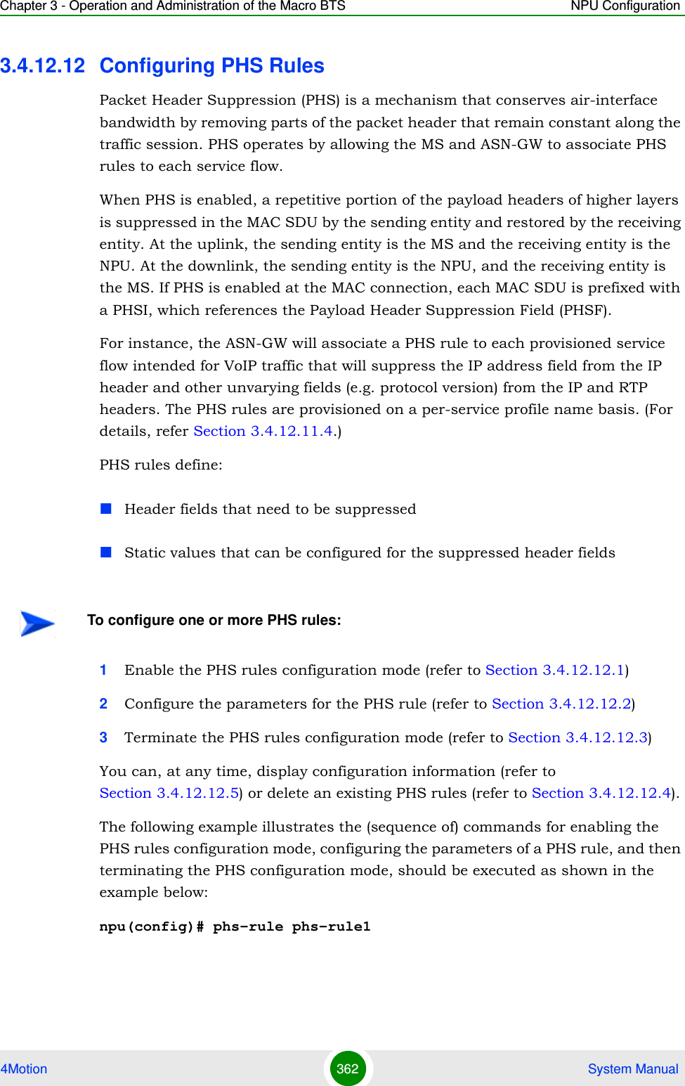
![Chapter 3 - Operation and Administration of the Macro BTS NPU Configuration4Motion 363 System Manualnpu(config-phsrule)# config field 000000000000000000000000FFFFFFFF00000000 mask 000F00 verify 0 size 20npu(config-phsrule)# exit3.4.12.12.1 Enabling the PHS Rules Configuration Mode /Creating a New PHS RuleTo configure the parameters for a PHS rule, first enable the PHS rules configuration mode. Run the following command to enable the PHS rules configuration mode. You can also use this command to create a new PHS rule.npu(config)# phs-rule <rulename>If you use this command to create a new PHS rule, the configuration mode for this PHS rule is automatically enabled, after which you can configure the parameters for the PHS rule (refer to Section 3.4.12.12.2). You can then terminate the PHS rules configuration mode (refer to Section 3.4.12.12.3) and return to the global configuration mode.3.4.12.12.2 Configuring Parameters for the PHS RuleRun the following command to configure the parameters of the PHS rule:npu(config-phsrule)# config <[field <value>] [mask <value>] [verify <value>] [size <value>]>Command Syntaxnpu(config)# phs-rule <rulename>Privilege Level10Syntax Description Parameter Description Presence Default ValuePossible Values<rulename> Denotes the PHS rule for which the PHS configuration mode is to be enabled.Mandatory N/A String (1 to 30 characters)Command ModesGlobal configuration mode](https://usermanual.wiki/Alvarion-Technologies/MICRO-25.Manual-p3/User-Guide-1329244-Page-114.png)
![Chapter 3 - Operation and Administration of the Macro BTS NPU Configuration4Motion 364 System ManualNOTEYou can display configuration information for specific or all PHS rules. For details, refer Section 3.4.12.12.5.IMPORTANTAn error may occur if you provide an invalid value for any of these parameters. Refer the syntax description for more information about the appropriate values and format for configuring these parameters.Command Syntaxnpu(config-phsrule)# config <[field <value>] [mask <value>] [verify <value>] [size <value>]>Privilege Level10Syntax Description Parameter Description Presence Default ValuePossible Values[field <value>] Denotes the PHSF value, that is, the header string to be suppressed. Mandatory N/A String. This parameter is of format "0x0000000000000000000000000000000000000000". Here Octet(x), x=20 bytes, each Byte will represent two characters when used as string like in xml file.](https://usermanual.wiki/Alvarion-Technologies/MICRO-25.Manual-p3/User-Guide-1329244-Page-115.png)
![Chapter 3 - Operation and Administration of the Macro BTS NPU Configuration4Motion 365 System Manual3.4.12.12.3 Terminating the PHS Rules Configuration ModeRun the following command to terminate the PHS rules configuration mode:npu(config-phsrule)# exit[mask <value>] Indicates the PHSM, which contains the bit-mask of the PHSF with the bits set that is to be suppressed.Mandatory N/A String This parameter is of format "0x000000". Here Octet(x), x=3 bytes, each Byte will represent two characters when used as string like in xml file.[verify <value>] Indicates whether the PHS header is to be verified.Optional 0 (No) 0: Indicates that the PHS header should not be verified.1: Indicates that the PHS header should be verified.[size <value>]Indicates the size in bytes of the header to be suppressed.Mandatory N/A 0-20Command ModesPHS rules configuration modeCommand Syntaxnpu(config-phsrule)# exitPrivilege Level10Command ModesPHS rules configuration mode](https://usermanual.wiki/Alvarion-Technologies/MICRO-25.Manual-p3/User-Guide-1329244-Page-116.png)
![Chapter 3 - Operation and Administration of the Macro BTS NPU Configuration4Motion 366 System Manual3.4.12.12.4 Deleting PHS RulesRun the following command to delete one or all PHS rules:npu(config)# no phs-rule [<rulename>]3.4.12.12.5 Displaying Configuration Information for PHS Rules To display all or specific PHS rules, run the following command:npu# show phs-rule [<rulename>]Specify the rule name if you want to display configuration information for a particular PHS rule. Do not specify a value for this parameter if you want to view configuration information for all PHS rule.CAUTIONSpecify the rule name if you want to delete a specific PHS rule. Otherwise all the configured PHS rules are deleted.Command Syntaxnpu(config)# no phs-rule [<rulename>]Privilege Level10Syntax Description Parameter Description Presence Default ValuePossible Values[<rulename>] Denotes the rule name of the PHS rule that you want to delete. Specify a value for this parameter if you want to delete a specific PHS rule. Do not specify a value for this parameter, if you want to delete all PHS rules. Optional N/A StringCommand ModesGlobal configuration mode](https://usermanual.wiki/Alvarion-Technologies/MICRO-25.Manual-p3/User-Guide-1329244-Page-117.png)
![Chapter 3 - Operation and Administration of the Macro BTS NPU Configuration4Motion 367 System Manual3.4.12.13 Managing the Hot-Lining FeatureHot-Lining provides a WiMAX operator with the capability to efficiently address issues with users that would otherwise be unauthorized to access packet data services. When Hot-Lining is enabled, the ASN-GW implements UL/DL traffic filters. These traffic filters are dynamically applied and removed per MSID. Triggers for filter IMPORTANTAn error may occur if you provide an invalid value for the rulename parameter. Refer the syntax description for more information about the appropriate values and format for configuring this parameter.Command Syntaxnpu# show phs-rule [<rulename>]Privilege Level1Syntax Description Parameter Description Presence Default ValuePossible Values[<rulename>] Denotes the rule name of the PHS rule that you want to display. Specify a value for this parameter if you want to display the parameters of a specific PHS rule. Do not specify a value for this parameter, if you want to display all PHS rules. Optional N/A StringDisplay FormatPHS Configuration :rulename field mask verify size<value> <value> <value> <value> <value>Command ModesGlobal command mode](https://usermanual.wiki/Alvarion-Technologies/MICRO-25.Manual-p3/User-Guide-1329244-Page-118.png)
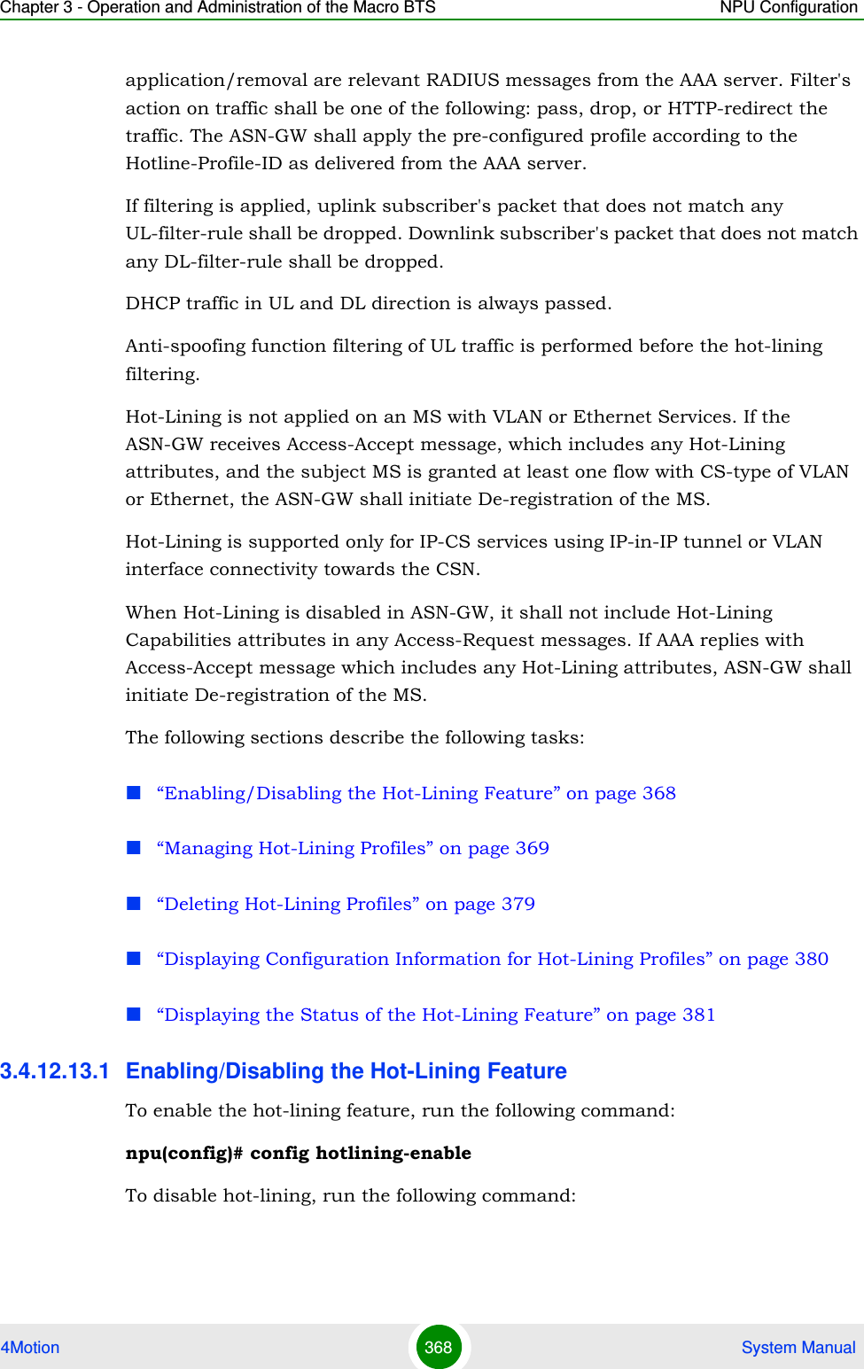
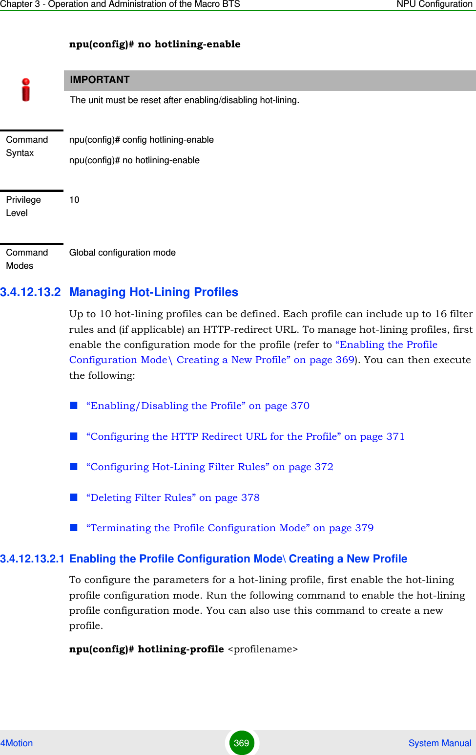
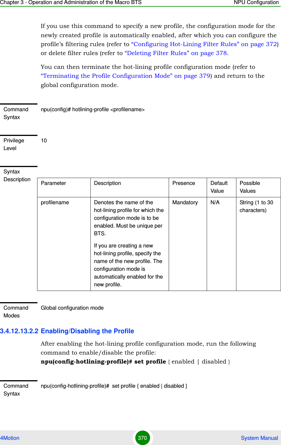
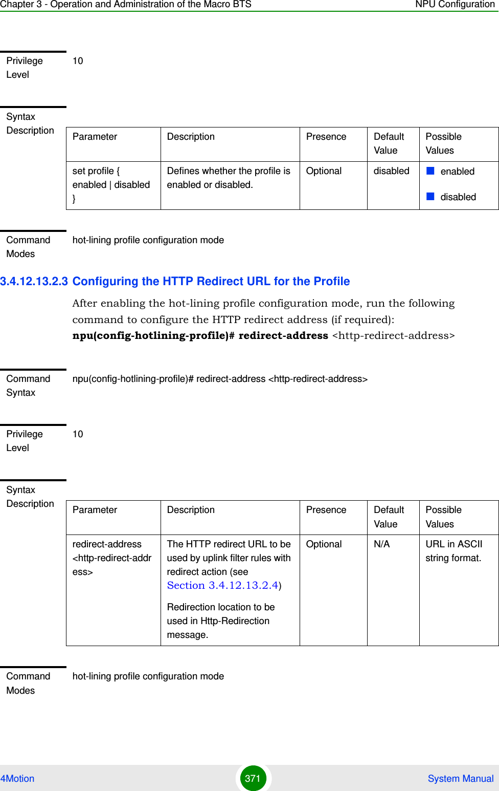
![Chapter 3 - Operation and Administration of the Macro BTS NPU Configuration4Motion 372 System Manual3.4.12.13.2.4 Configuring Hot-Lining Filter RulesUp to 16 filter rules can be defined for each hot-lining profile. To manage a filter rule, first enable the hot-lining configuration mode for the filter rule (refer to “Enabling the Filtering Rule Configuration Mode\ Creating a New Filtering Rule” on page 372). You can then execute the following:“Configuring IP Address Parameters for the Filter Rule” on page 373“Configuring Source Port Range Parameters for the Filter Rule” on page 374“Configuring Destination Port Range Parameters for the Filter Rule” on page 375“Configuring DSCP Range Parameters for the Filter Rule” on page 376“Configuring IP Protocol Parameter for the Filter Rule” on page 377“Restoring the Default Values of Filter Rule Components” on page 377You can then terminate the filter configuration mode (refer to “Terminating the Filter Rule Configuration Mode” on page 378) and return to the hotlining profile configuration mode.3.4.12.13.2.4.1Enabling the Filtering Rule Configuration Mode\ Creating a New Filtering RuleTo configure the parameters for a filter rule, first enable the filter rule configuration mode. Run the following command to enable the filter rule configuration mode. You can also use this command to create a new filter rule.npu(config-hotlining-profile)# filter-rule <string> [ direction { uplink | downlink } ] [ action { drop | pass | redirect } ]If you use this command to specify a new filter rule, the configuration mode for the newly created filter rule is automatically enabled, after which you can configure the filter rule’s parameters.You can then terminate the filter rule configuration mode and return to the profile configuration mode.NOTEFiltering Rules can be added/updated only when the Profile is disabled.](https://usermanual.wiki/Alvarion-Technologies/MICRO-25.Manual-p3/User-Guide-1329244-Page-123.png)
![Chapter 3 - Operation and Administration of the Macro BTS NPU Configuration4Motion 373 System ManualThe priority of checking for a match in filter rules is applied with respect to the sequence in which these filter rules were defined. The first found match is applied. 3.4.12.13.2.4.2Configuring IP Address Parameters for the Filter RuleAfter enabling the filter rule configuration mode, run the following command to configure the IP address parameters of the filter rule:npu(config-hotlining-filter-rule)# ip-address <ipV4Addr> [<netMask>]Command Syntaxnpu(config-hotlining-profile)# filter-rule <string> [ direction { uplink | downlink } ] [ action { drop | pass | redirect } ]Privilege Level10Syntax Description Parameter Description Presence Default ValuePossible Valuesfilter-rule <string> Denotes the unique (per BTS) name of the filter rule for which the configuration mode is to be enabled. If you are creating a new filter rule, specify the name of the new rule. The configuration mode is automatically enabled for the new filter rule.Mandatory N/A String (1 to 30 characters)direction { uplink | downlink }The direction for which the rule should be applied.Optional uplink uplinkdownlinkaction { drop | pass | redirect }Action to be performed on packets that match the rule,redirect is applicable only if direction is uplink. If set to redirect then redirect-address (see Section 3.4.12.13.2.3) must be defined.Optional pass droppassredirectCommand Modeshot-lining profile configuration mode](https://usermanual.wiki/Alvarion-Technologies/MICRO-25.Manual-p3/User-Guide-1329244-Page-124.png)
![Chapter 3 - Operation and Administration of the Macro BTS NPU Configuration4Motion 374 System ManualIf you do not configure IP address parameters for the filter rule, the default IP address (0.0.0.0) and subnet mask (0.0.0.0) will be used, meaning that IP address is ignored.3.4.12.13.2.4.3Configuring Source Port Range Parameters for the Filter RuleAfter enabling the filter rule configuration mode, run the following command to configure the source port parameters of the filter rule:npu(config-hotlining-filter-rule)# source-port start <port-number(0-65535)> stop <port-number(0-65535)>If you do not configure source port parameters for the filter rule, the default values will be used, meaning that source port is ignored.Command Syntaxnpu(config-hotlining-filter-rule)# ip-address <ipV4Addr> [<netMask>]Privilege Level10Syntax Description Parameter Description Presence Default ValuePossible Values<ipV4Addr> If direction is downlink then this is the downlink Source IP Address.If direction is uplink then this is the uplink Destination IP Address255.255.255.255 means not applicable (ignore this condition).Optional 255.255.255.255ip address[<netMask>] Defines Subnet Mask associated with the configured IP address.Optional 255.255.255.255subnet maskCommand Modeshotlining filter rule configuration mode](https://usermanual.wiki/Alvarion-Technologies/MICRO-25.Manual-p3/User-Guide-1329244-Page-125.png)
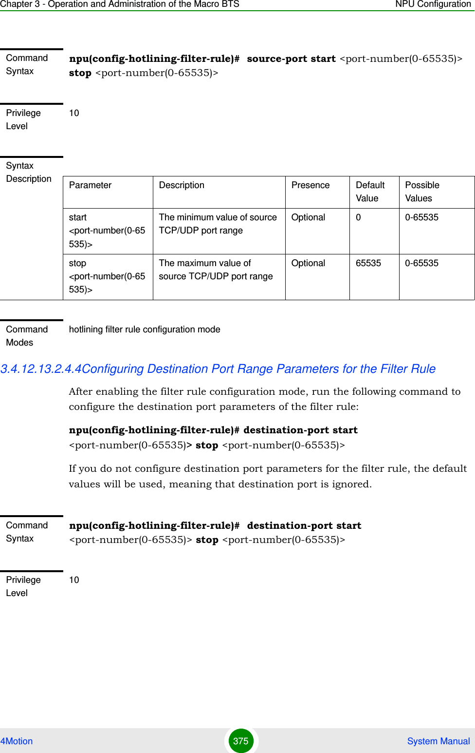
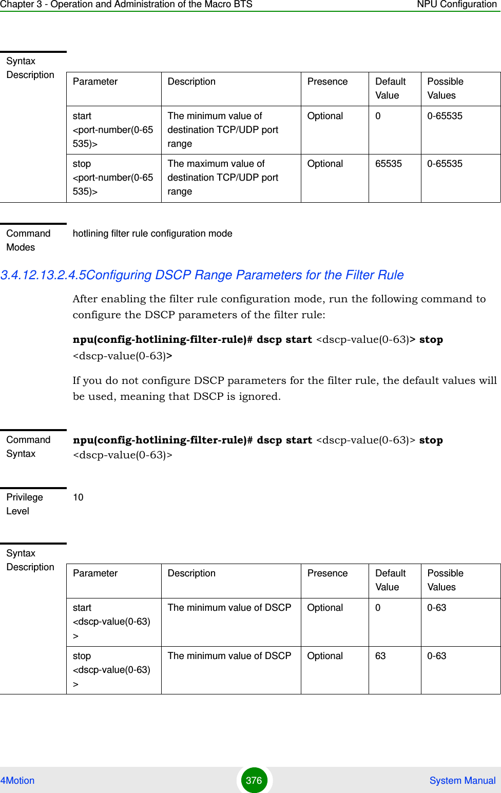
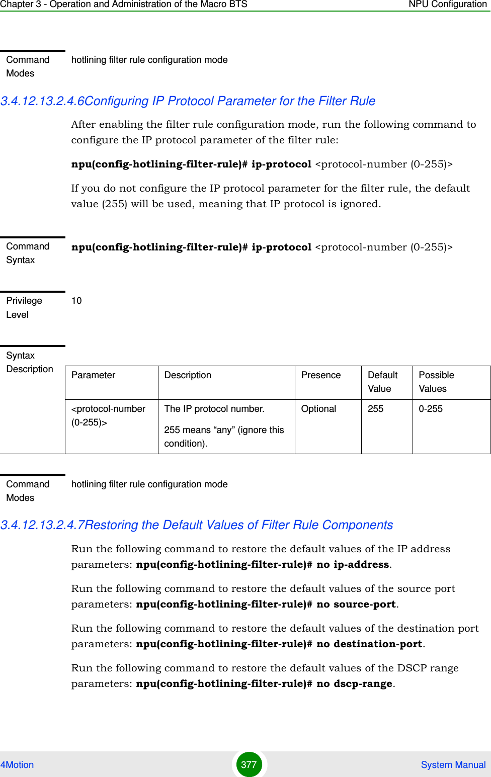
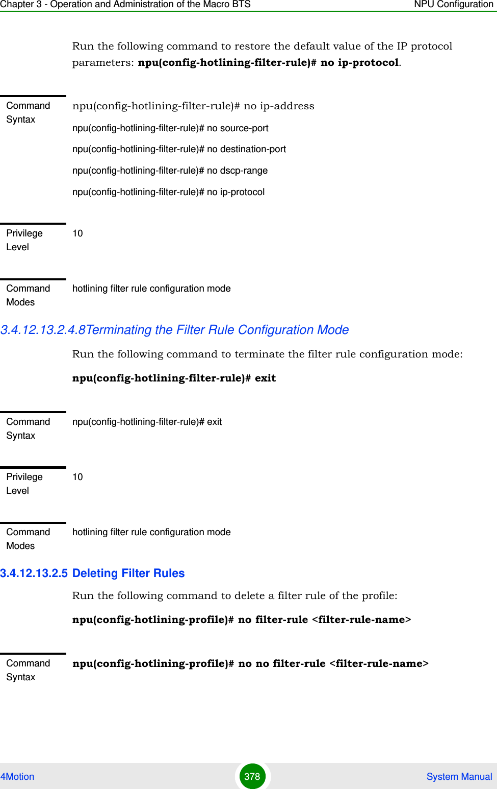
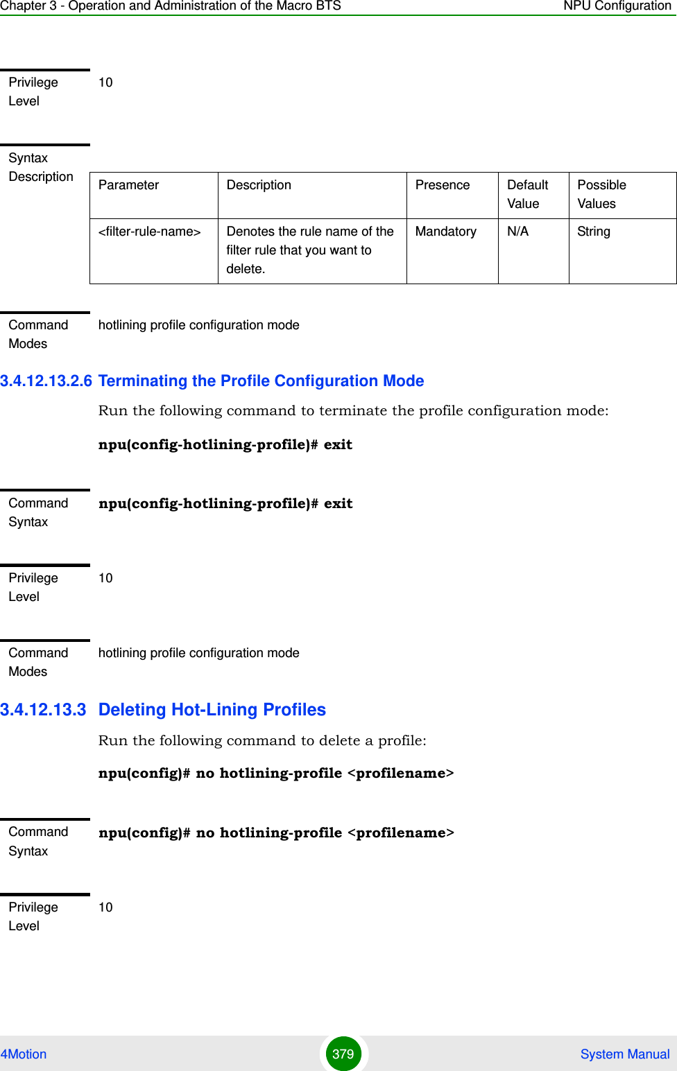
![Chapter 3 - Operation and Administration of the Macro BTS NPU Configuration4Motion 380 System Manual3.4.12.13.4 Displaying Configuration Information for Hot-Lining Profiles To display all or specific profiles, run the following command:npu# show hotlining-profile [<profilename>]Specify the rule name if you want to display configuration information for a particular profile. Do not specify a value for this parameter if you want to view configuration information for all profiles.Syntax Description Parameter Description Presence Default ValuePossible Values<profilename> Denotes the profile name of the profile that you want to delete. Mandatory N/A StringCommand Modeshotlining profile configuration modeCommand Syntaxnpu# show hotlining-profile [<profilename>]Privilege Level1Syntax Description Parameter Description Presence Default ValuePossible Values[<profilename>] Denotes the profile name of the profile that you want to display. Specify a value for this parameter if you want to display the parameters of a specific profile. Do not specify a value for this parameter, if you want to display all profiles.Optional null String](https://usermanual.wiki/Alvarion-Technologies/MICRO-25.Manual-p3/User-Guide-1329244-Page-131.png)
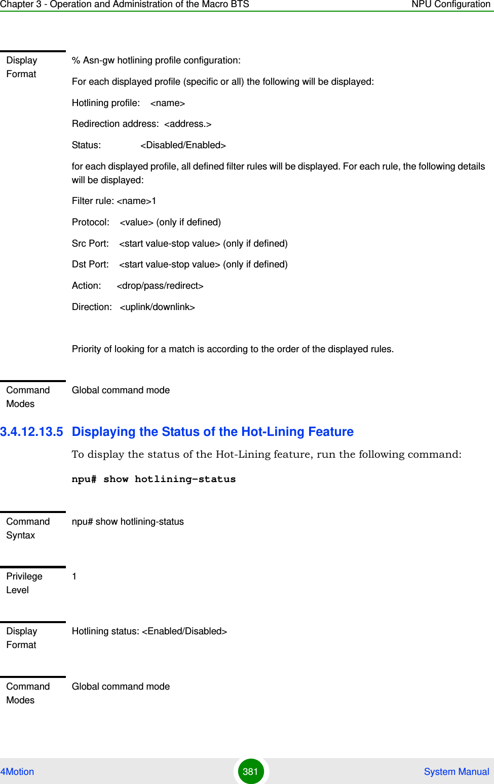
![Chapter 3 - Operation and Administration of the Macro BTS NPU Configuration4Motion 383 System ManualIf the ASN-GW is the authenticator for the MS(s) the failing BS served, then in addition to context clearance it also sends R3 Accounting-Request (Stop) message including a release indication to AAA.When keep-alive fails, ASN-GW generates an event.Regardless of the enable/disable status of the keep-alive mechanism in the ASN-GW, it replies to ASN_Keep_Alive_Req received from other BSs with ASN_Keep_Alive_Rsp. that includes also its “Last-Reset-Time”. It responds only if all its functions operate properly. In case one of the functions fails, the ASN-GW shall not respond to the keep-alive poll.3.4.12.14.1 Configuring ASN-GW Keep-Alive ParametersTo configure one or several keep-alive parameters, run the following command:npu(config)# keep-alive ([asn-ka <enable|disable>] [period <integer (10-1000)>] [rtx-cnt <integer (0-10)>] [rtx-time <integer (5000-10000)>] )IMPORTANTAn error may occur if you provide an invalid value for any of these parameters. Refer to the syntax description for more information about the appropriate values and format for configuring these parameters.An error may occur if you provide configuration values that do not satisfy following condition: 'period*1000 >= rtx-time * (rtx-cnt + 1)'"At least one parameter must be specified (the value is optional): The command npu(config)# keep-alive will return an Incomplete Command error.Command Syntaxnpu(config)# keep-alive ([asn-ka <enable|disable>] [period <integer (10-1000)>] [rtx-cnt <integer (0-10)>] [rtx-time <integer (5000-10000)>]) Privilege Level10](https://usermanual.wiki/Alvarion-Technologies/MICRO-25.Manual-p3/User-Guide-1329244-Page-134.png)
![Chapter 3 - Operation and Administration of the Macro BTS NPU Configuration4Motion 384 System Manual3.4.12.14.2 Displaying Configuration Information for ASN-GW Keep-Alive Parameters To display the ASN-GW keep-alive parameters, run the following command:npu# show keep-aliveSyntax Description Parameter Description Presence Default ValuePossible Values[asn-ka <enable|disable>]Enable/Disable the ASN-GW keep-alive mechanism.Optional disable enabledisable[period <integer (10-1000)>]The period in seconds between polling sessions.period x 1000 (value in milliseconds) cannot be lower than rtx-time x (rtx-cnt +1).Optional 60 10-1000[rtx-cnt <integer (0-10)>]Maximum number of retries if rtx-time has expired without getting a response.Optional 5 1-10[rtx-time <integer (5000-10000)>]Time in milliseconds to wait for a response before initiating another polling attempt or reaching a decision that the polled entity has failed (if the maximum number of retries set by rtx-cnt has been reached).Optional 5000 5000-10000Command ModesGlobal configuration modeCommand Syntaxnpu# show keep-alivePrivilege Level1](https://usermanual.wiki/Alvarion-Technologies/MICRO-25.Manual-p3/User-Guide-1329244-Page-135.png)
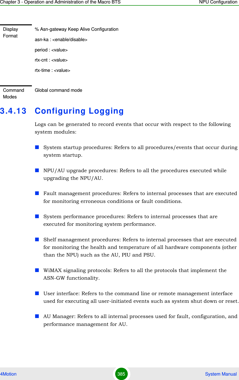
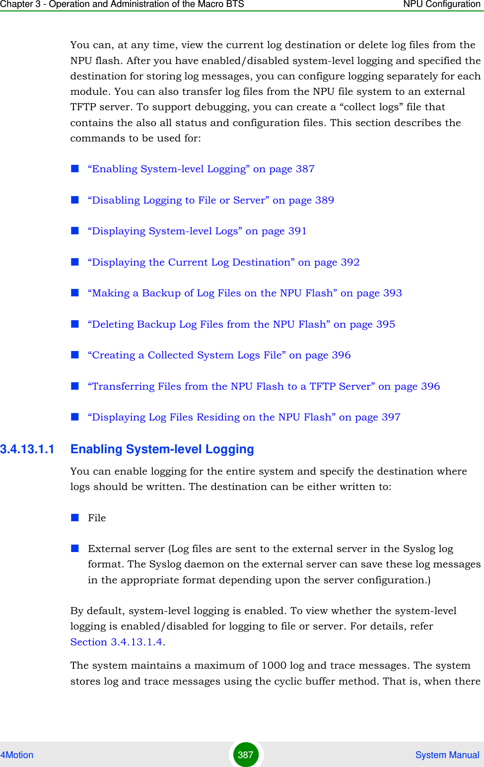
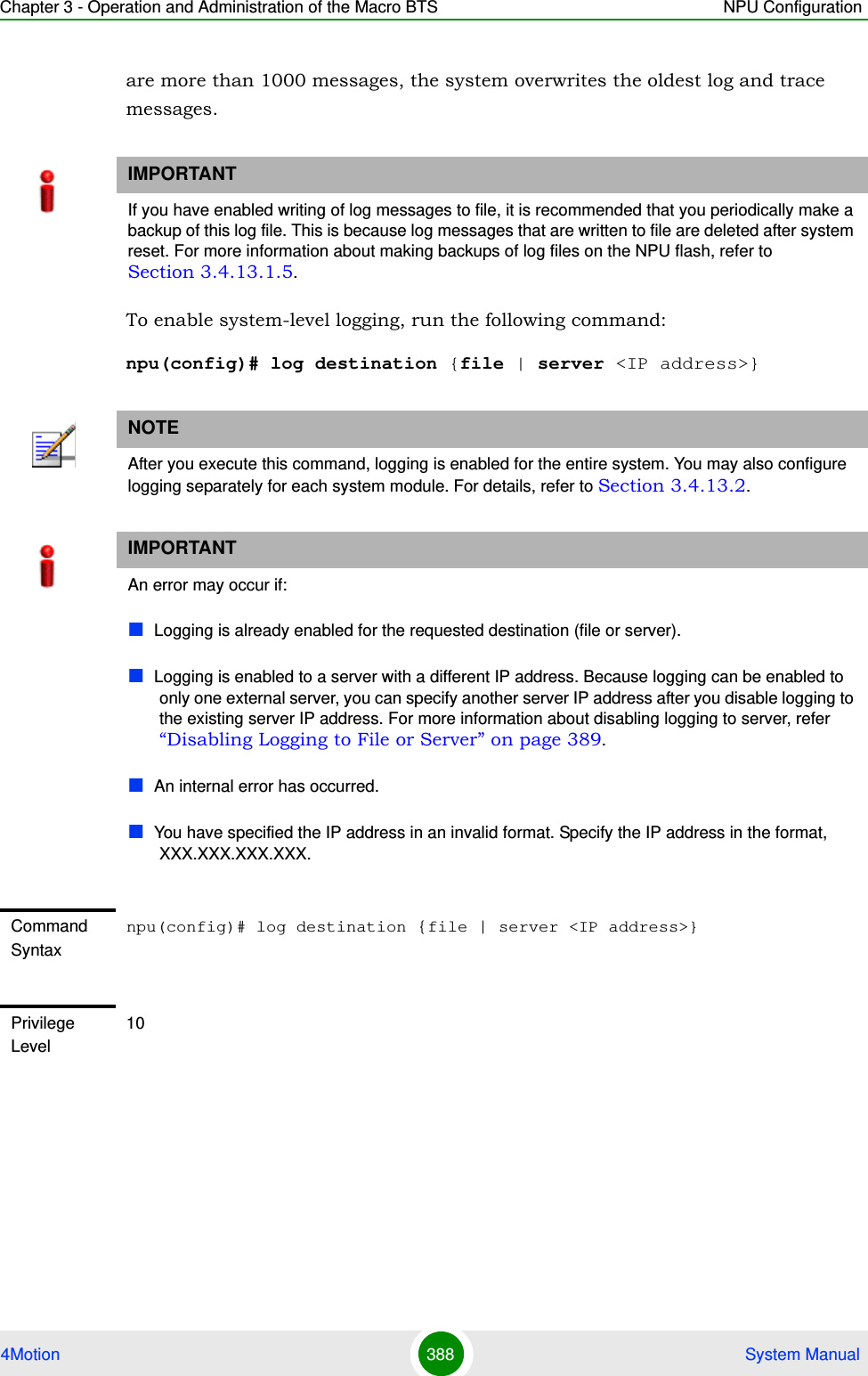
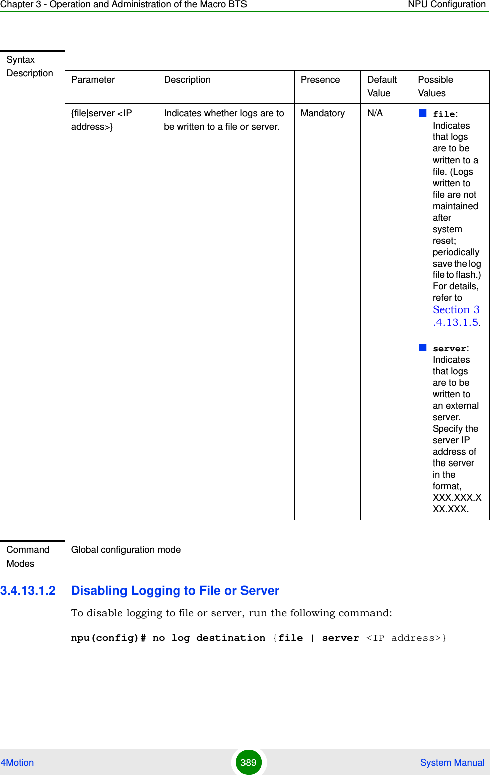
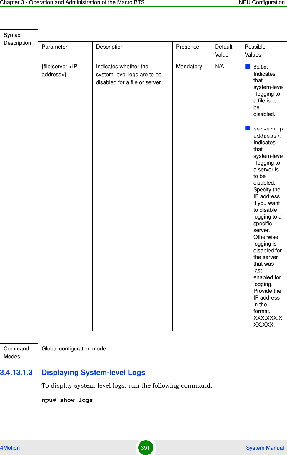
![Chapter 3 - Operation and Administration of the Macro BTS NPU Configuration4Motion 392 System ManualWhen you run this command, all the log messages are displayed. (4Motion maintains a maximum of 1000 log and trace messages.) If you want to filter log messages to be displayed, run the following command to specify the filter criteria:npu# show logs [| grep <search string>]For example, if you want to view log messages pertaining to only Error logs, run the following command:npu# show logs |grep ERROR3.4.13.1.4 Displaying the Current Log DestinationTo view the current log destination, that is, whether logs are written to file or an external server, run the following command:npu# show log destinationIMPORTANTAn error may occur if:There are no logs to be displayed.The log files are inaccessible or an internal error occurred while processing the result.Command Syntaxnpu# show logs [| grep <search string>]Privilege Level1Syntax Description Parameter Description Presence Default ValuePossible Values[ grep <search string>]Indicates the criteria for filtering the log messages to be displayed.Optional N/A StringCommand ModesGlobal command mode](https://usermanual.wiki/Alvarion-Technologies/MICRO-25.Manual-p3/User-Guide-1329244-Page-143.png)
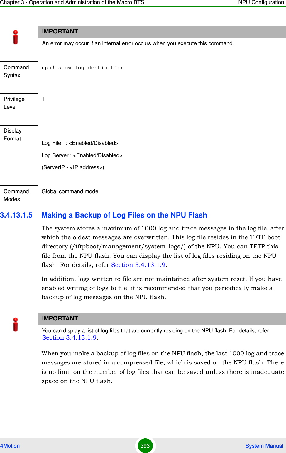
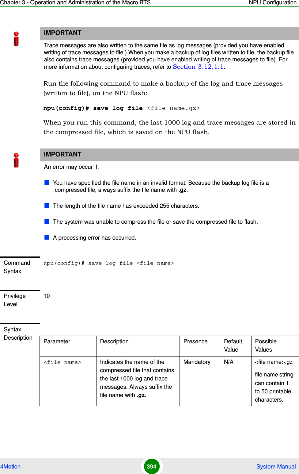
![Chapter 3 - Operation and Administration of the Macro BTS NPU Configuration4Motion 395 System Manual3.4.13.1.6 Deleting Backup Log Files from the NPU FlashYou can delete the backup log files from the NPU flash. It is recommended that you periodically make a backup of these log files, and delete these from the NPU flash.To delete log and trace backup files from the NPU flash, run the following command:npu(config)# erase log file [<file name>]Command ModesGlobal configuration modeIMPORTANTTrace and log messages are stored in the same backup file on the NPU flash. When you execute this procedure, trace messages are also deleted from the NPU flash. For details, refer to “Managing System-level Tracing” on page 671.CAUTIONSpecify the file name if you want to delete a specific backup file. Otherwise all the backup files residing in the NPU flash are deleted.IMPORTANTAn error may occur if:The file name that you have specified does not exist.A processing error has occurred.Command Syntaxnpu(config)# erase log file [<file name>]Privilege Level10](https://usermanual.wiki/Alvarion-Technologies/MICRO-25.Manual-p3/User-Guide-1329244-Page-146.png)
![Chapter 3 - Operation and Administration of the Macro BTS NPU Configuration4Motion 396 System Manual3.4.13.1.7 Creating a Collected System Logs FileTo create a collected system log file that contains all current logs, status and configuration files of the system run the following command:npu# collect logsThe name of the file is: system_logs_<Date & Time>.tar3.4.13.1.8 Transferring Files from the NPU Flash to a TFTP ServerTo transfer files from the NPU flash to a TFTP server, run the following command:npu# transfer logs [server-ip <ip-addr>] file {<file name (*.tar)> | All | Latest}Syntax Description Parameter Description Presence Default ValuePossible Values[<file name>] Indicates the name of the compressed log file to be deleted. If you do not specify the file name, all the log files residing in the NPU flash are deleted.Always suffix the file name with .gz.Optional N/A <file name>.gzCommand ModesGlobal configuration modeCommand Syntaxnpu# collect logsPrivilege Level10Command ModesGlobal command modeCommand Syntaxnpu# transfer logs [server-ip <ip-addr>] file {<file name (*.tar)> | All | Latest}](https://usermanual.wiki/Alvarion-Technologies/MICRO-25.Manual-p3/User-Guide-1329244-Page-147.png)
![Chapter 3 - Operation and Administration of the Macro BTS NPU Configuration4Motion 397 System Manual3.4.13.1.9 Displaying Log Files Residing on the NPU FlashYou can display a list of log files that are residing on the NPU flash. For details, refer Section 3.11.2.3.4.13.2 Configuring Module-level LoggingYou can configure logging (enable/disable) separately for the following modules, and define the severity level for which logging is required:System startup proceduresNPU/AU upgrade proceduresFault management proceduresSystem performance proceduresShelf management proceduresWiMAX signaling protocolsUser interfacePrivilege Level10Syntax Description Parameter Description Presence Default ValuePossible Values[<ip-addr>] Indicates the IP address of the destination TFTP server.Mandatory N/A IP address{<file name (*.tar)> | All | Latest}The file(s) to be transferred:<file name>.tar: A selected file that exists in the flash.All: All files in the flash.Latest: The latest created file.Mandatory N/A <file name (*.tar)>All LatestCommand ModesGlobal command mode](https://usermanual.wiki/Alvarion-Technologies/MICRO-25.Manual-p3/User-Guide-1329244-Page-148.png)
![Chapter 3 - Operation and Administration of the Macro BTS NPU Configuration4Motion 398 System ManualAU management proceduresThis section describes the commands to be used for:“Configuring the Log Severity Level” on page 398“Displaying Configuration Information for Module-level Logging” on page 400“Disabling Module-level Logging” on page 4013.4.13.2.1 Configuring the Log Severity LevelYou can configure the severity level for logs to be generated for each module. This means that if an event occurs for a module for which the severity level is equal to or higher than the configured level, a log is generated. The following are the severity levels (highest to lowest) that can be configured for each module:AlertErrorInformationTo specify the severity level for each module for which logs are to be created, run the following command:npu(config)# log level [{StartupMgr|SWDownload|FaultMgr|PerfMgr|ShelfMgr|SIGASN|UserIF|AUMgr}] {ALERT|ERROR|INFO}The parameters in this command correspond to the system modules/procedures listed in the following table:IMPORTANTBy default, logging is enabled for all modules, and the severity level is Error. The severity levels recorded in 4Motion log messages are defined in RFC 3164.Table 3-24: Modules for which Logging can be EnabledParameter Refers to...StartupMgr System startup proceduresSWDownload Software upgrade procedures](https://usermanual.wiki/Alvarion-Technologies/MICRO-25.Manual-p3/User-Guide-1329244-Page-149.png)