Alvarion Technologies MICRO-25 Microbase station transceiver User Manual 4Motion System Manual
Alvarion Technologies Ltd. Microbase station transceiver 4Motion System Manual
Contents
- 1. Manual p1
- 2. Manual p2
- 3. Manual p3
- 4. Manual p4
- 5. Manual p5
Manual p5
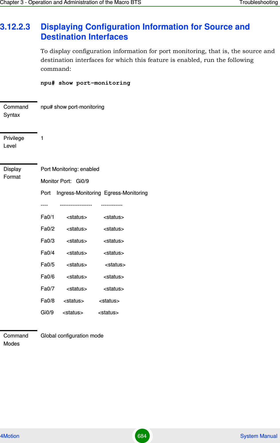
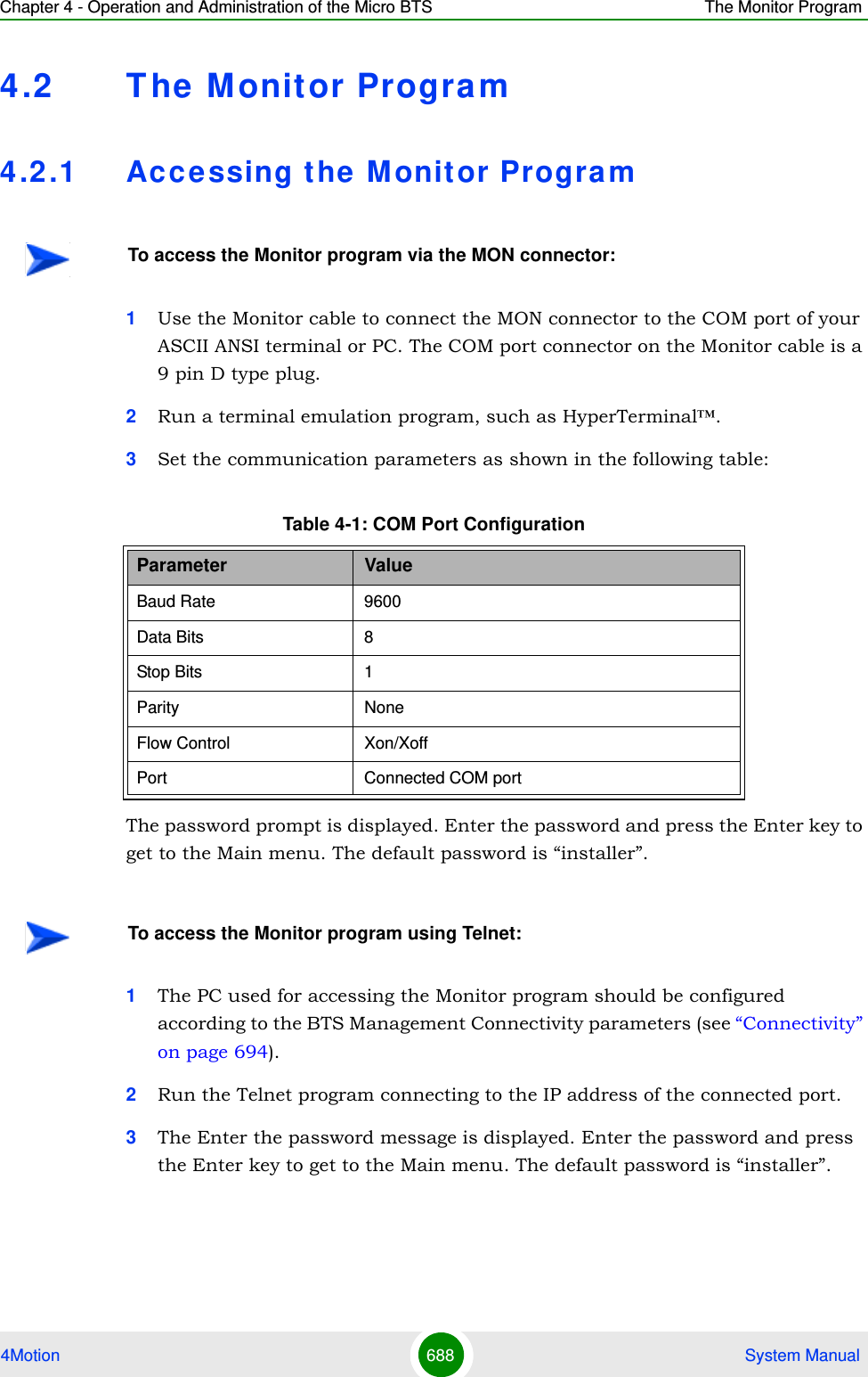
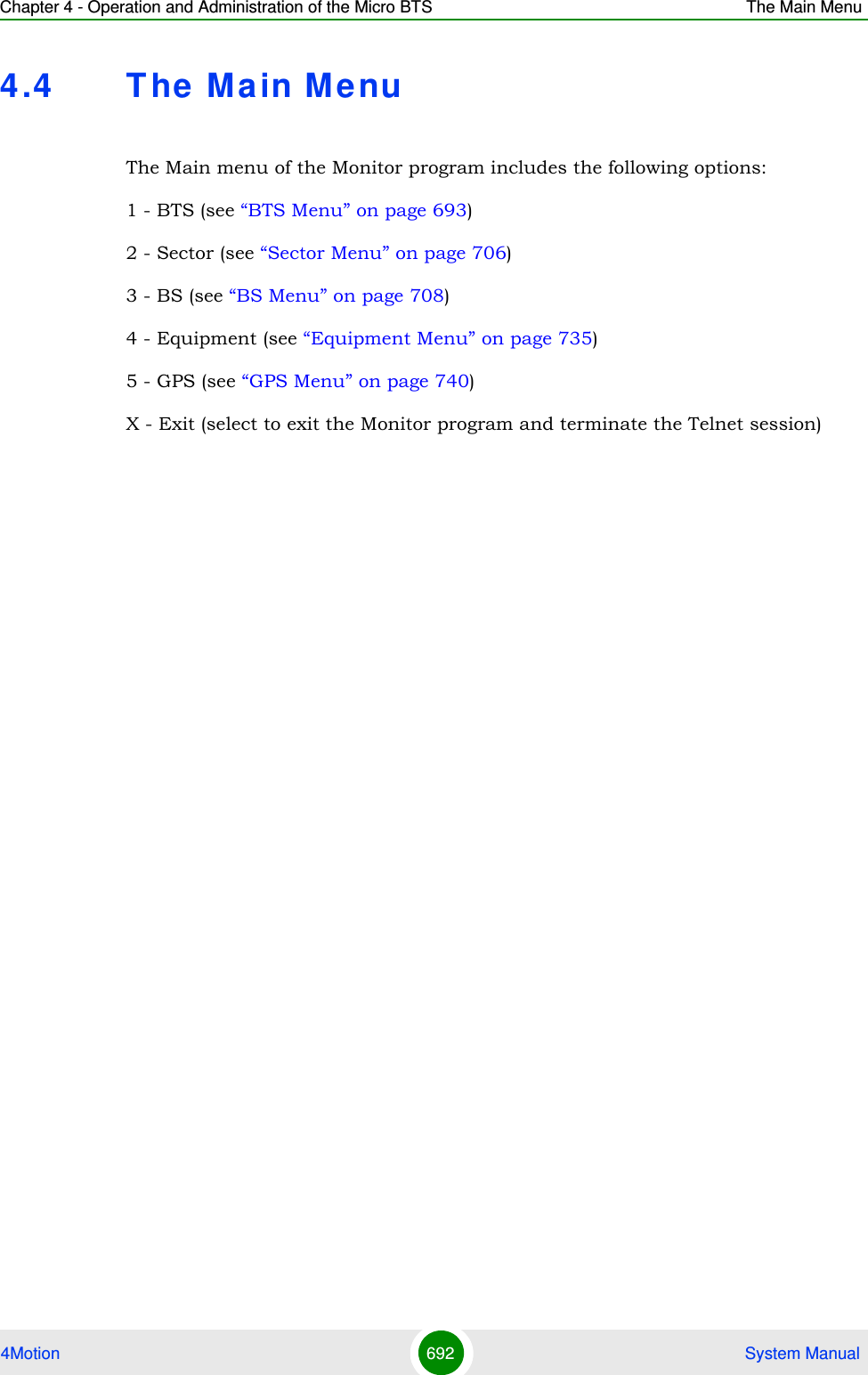
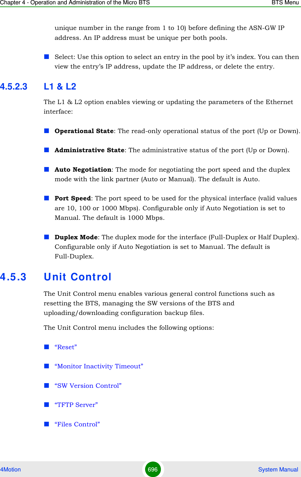
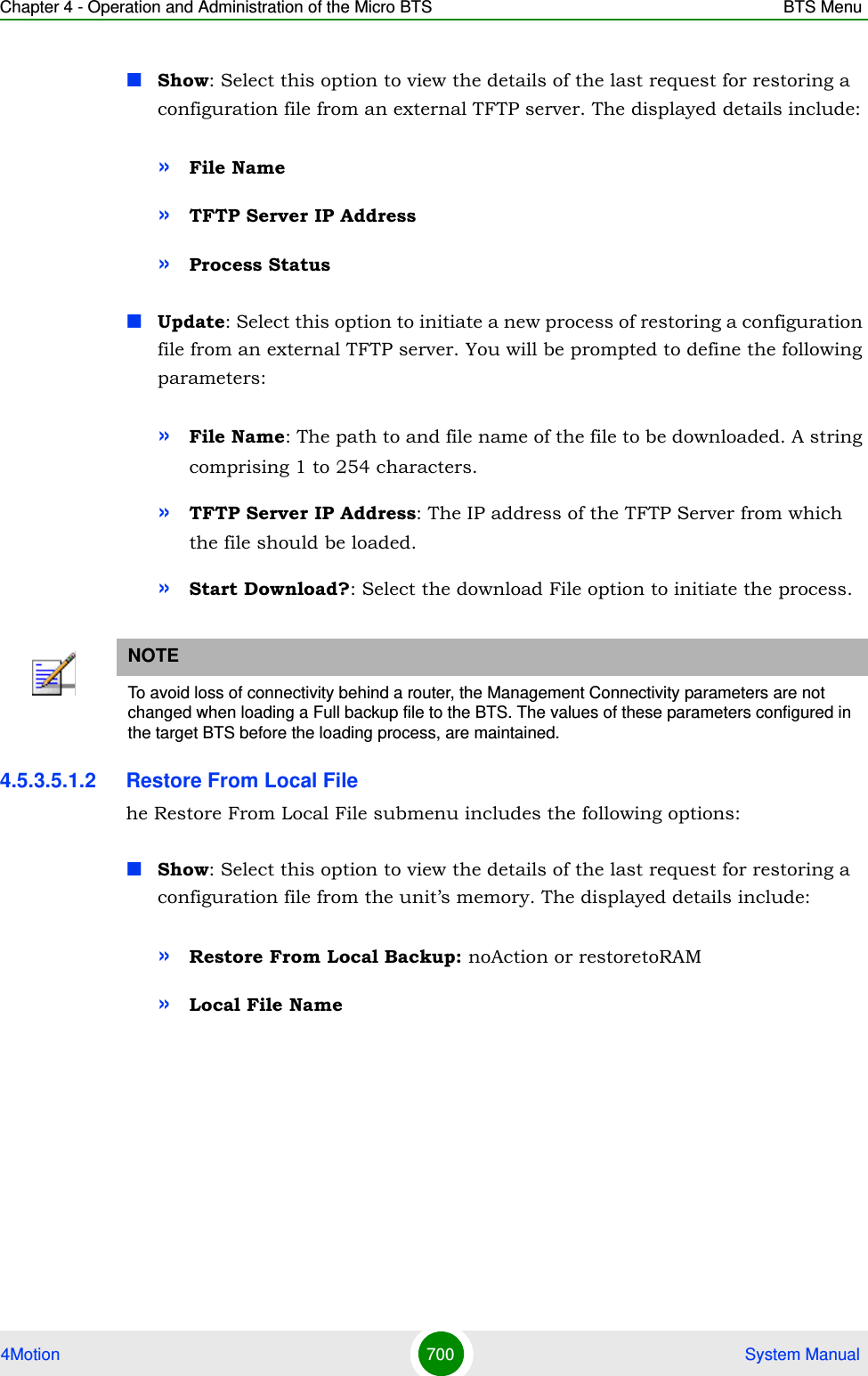
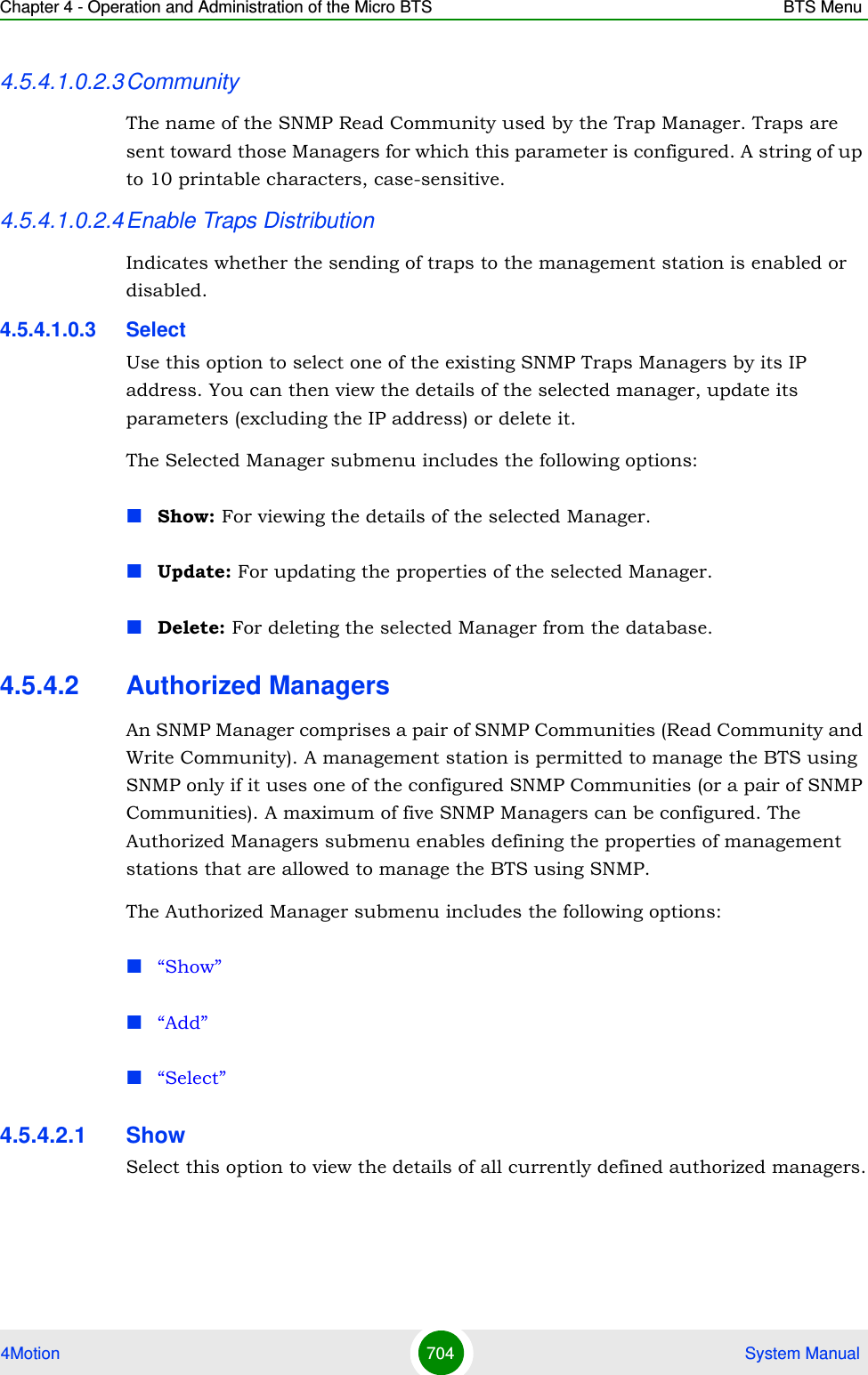
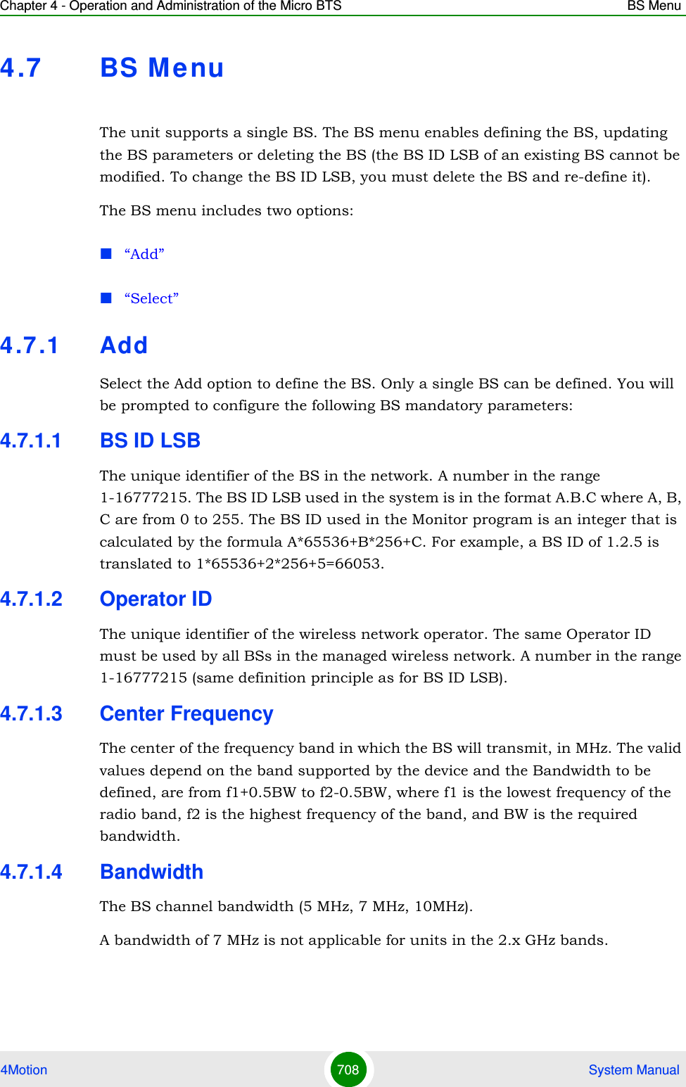
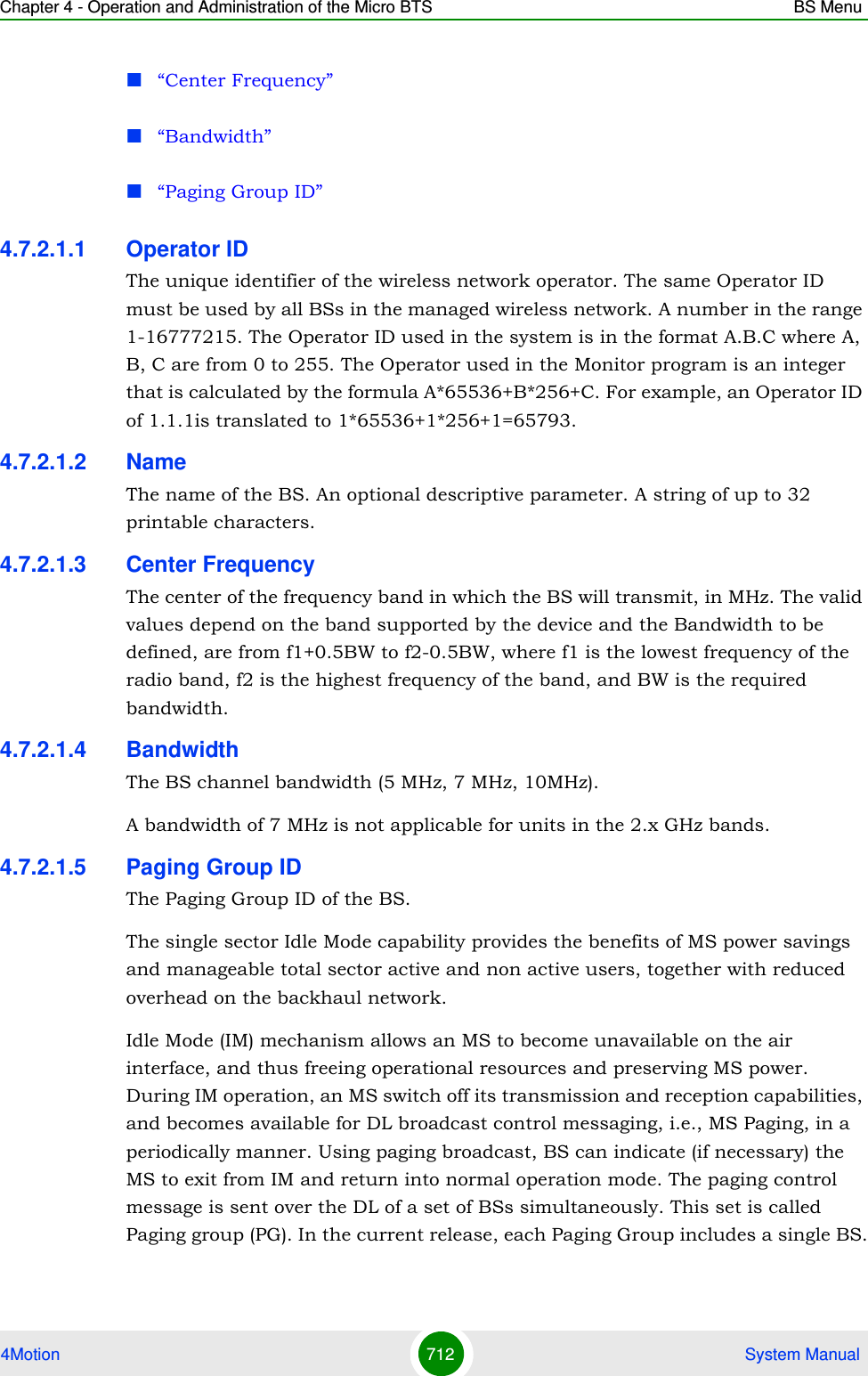
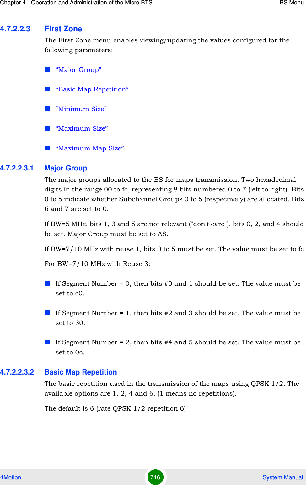
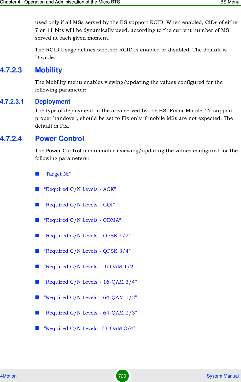
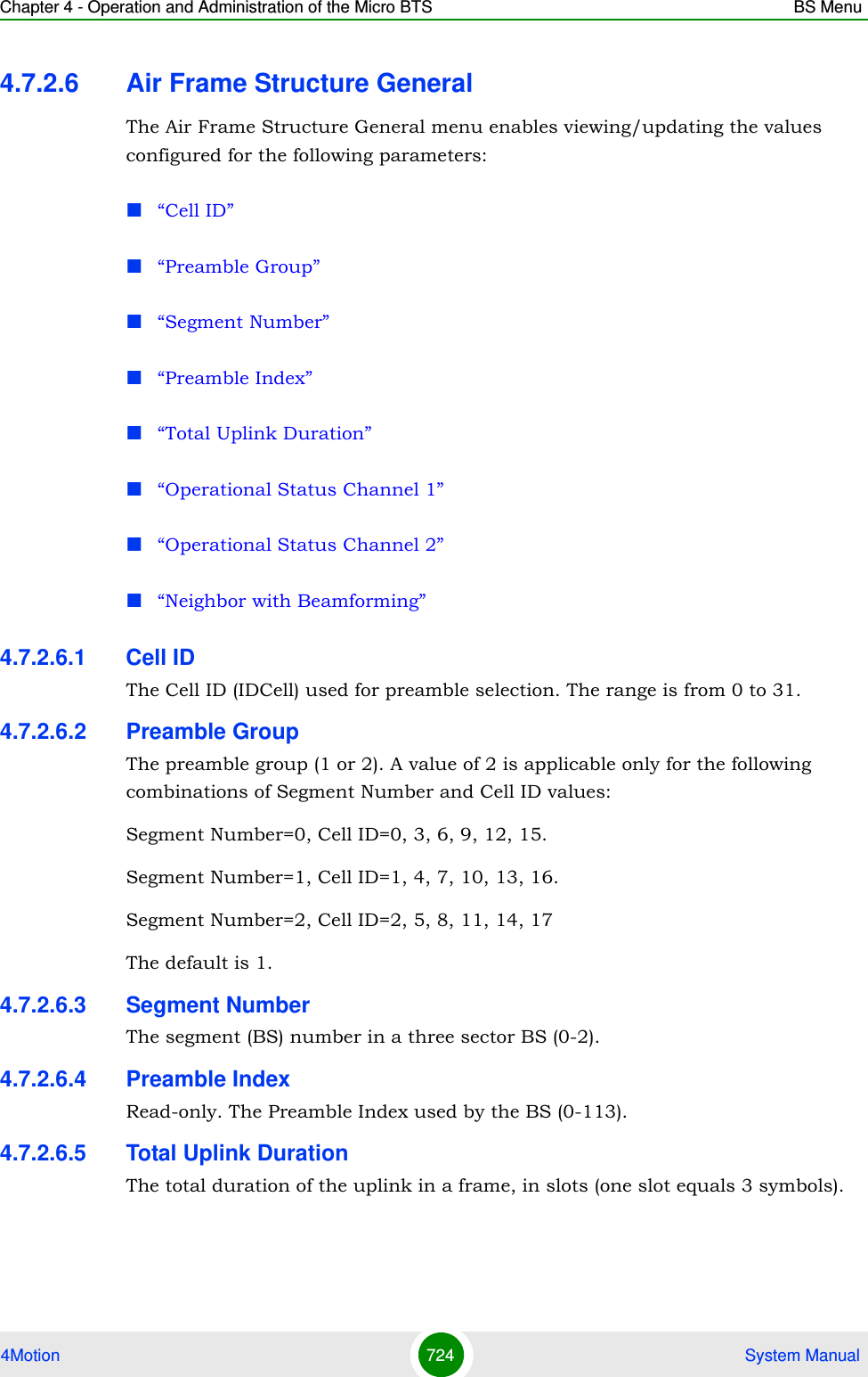
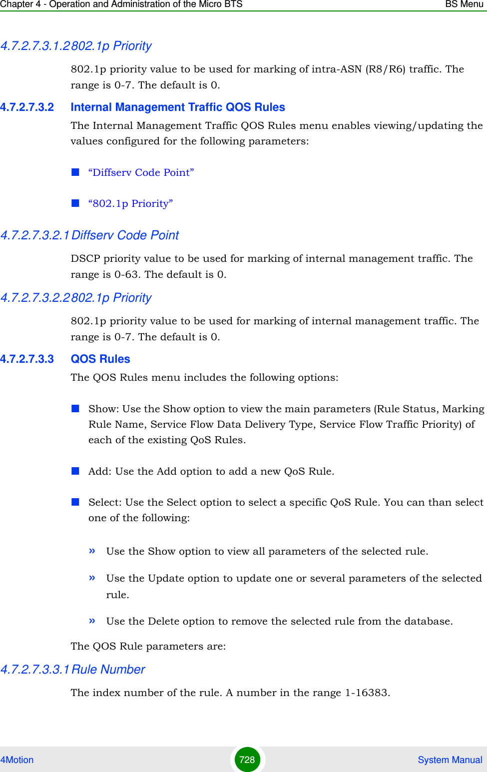
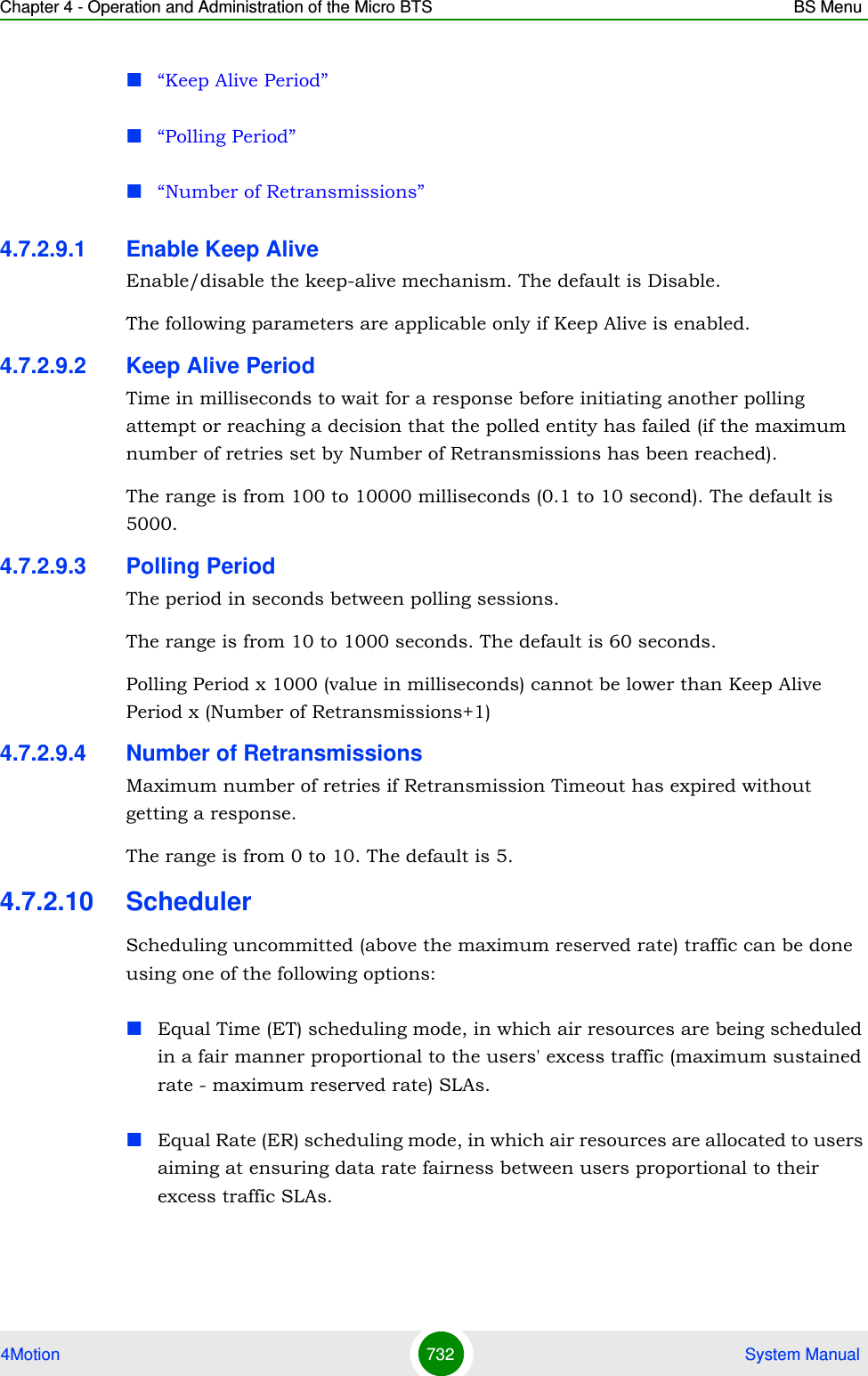
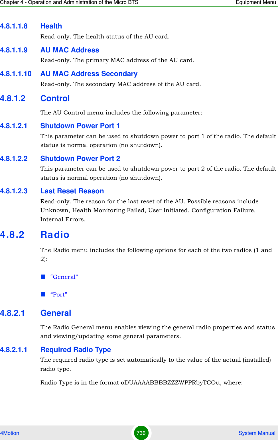
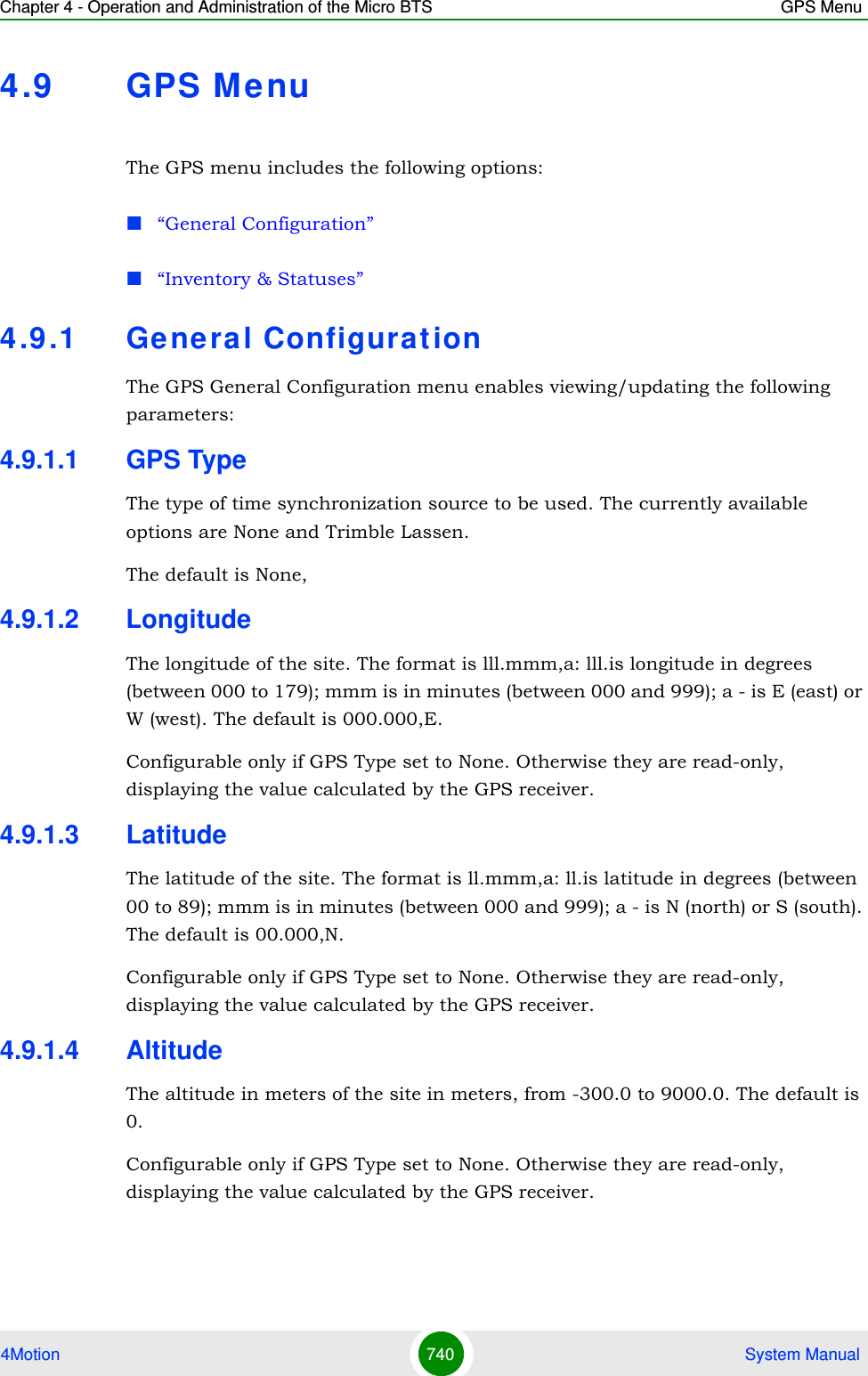
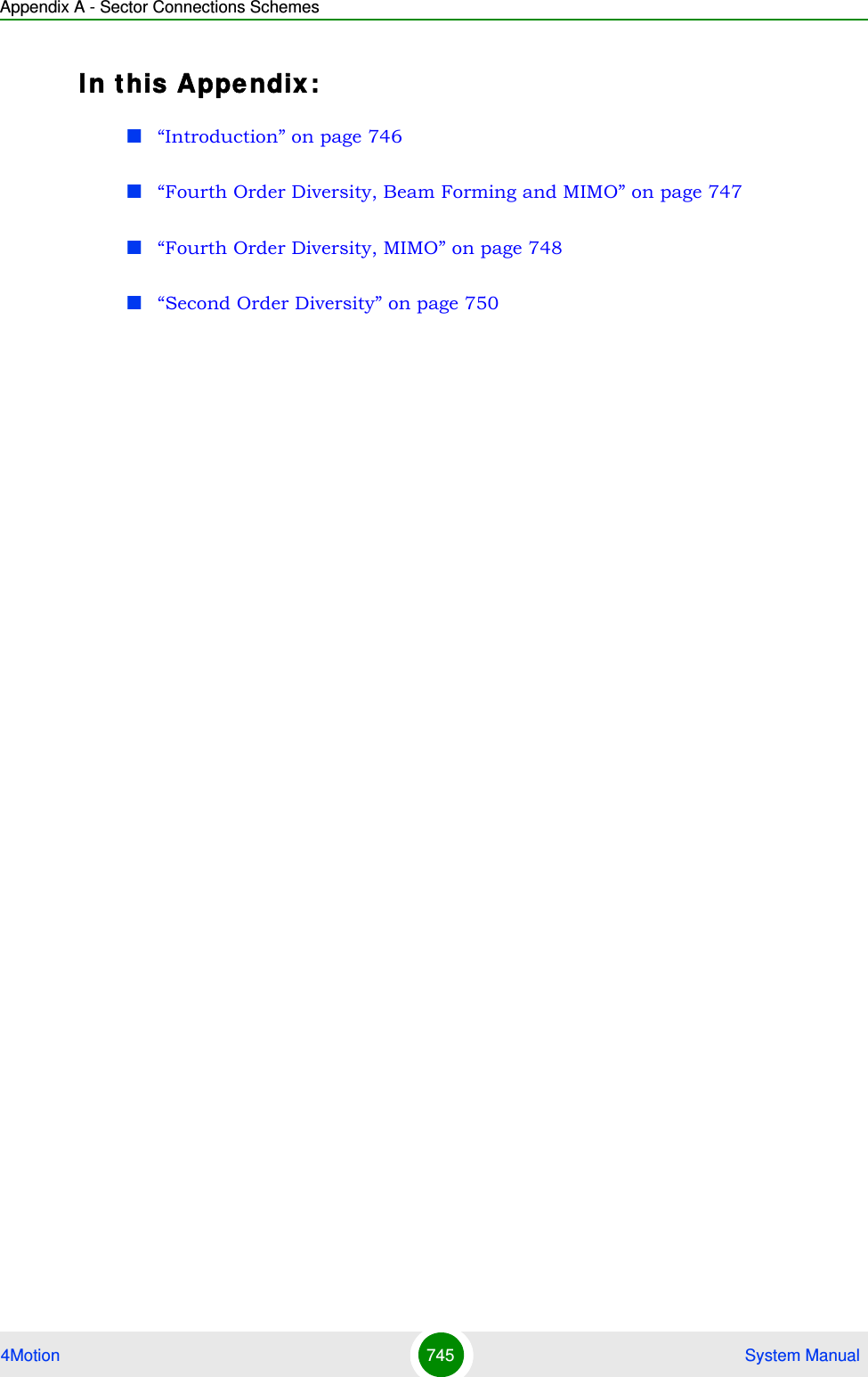
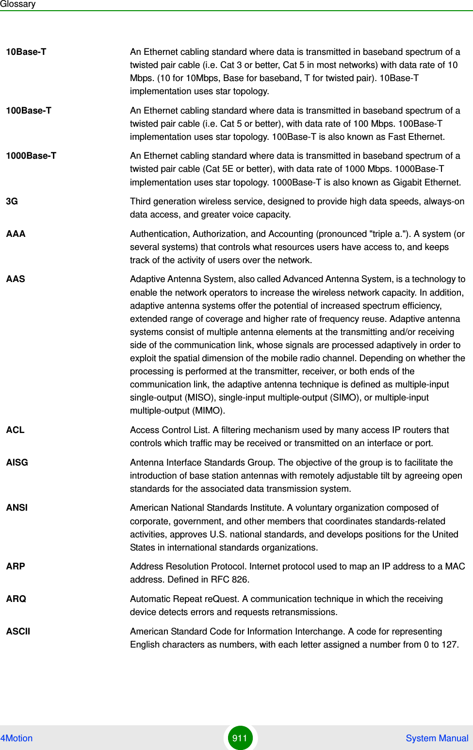
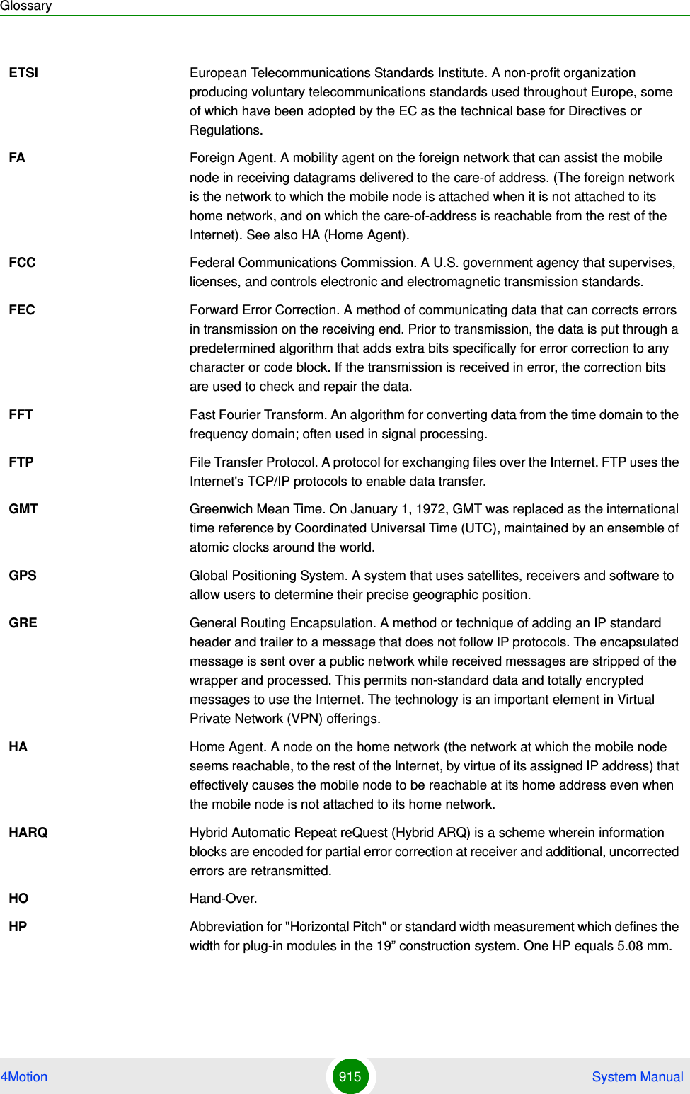
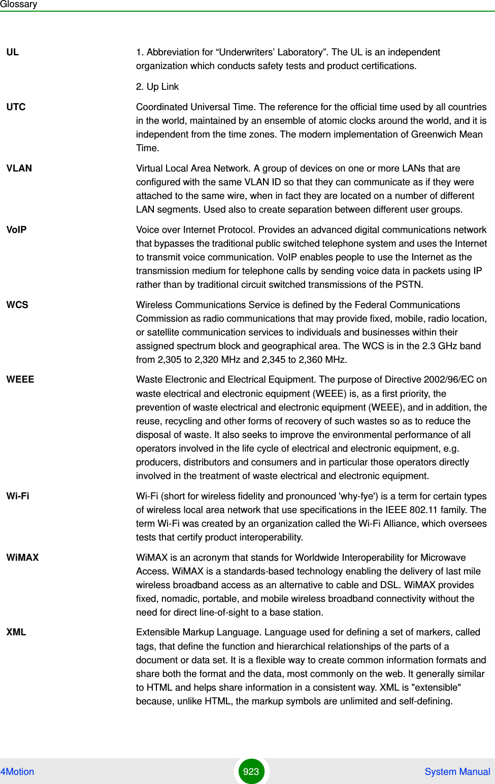
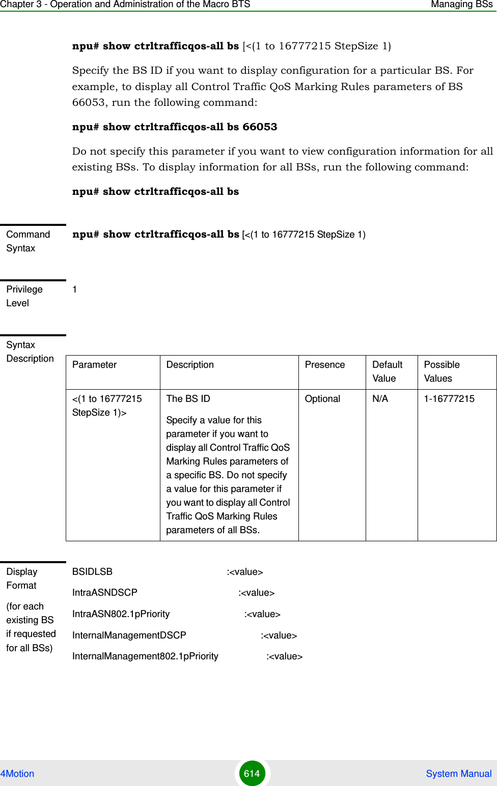
![Chapter 3 - Operation and Administration of the Macro BTS Managing BSs4Motion 548 System Manual3.9.9.7.2 Displaying Configuration Information for Neighbor BS Required C/N Level ParametersTo display configuration for the Neighbor BS Required C/N Level parameters, run the following command:npu# show nbr-requiredcnr bs [<(1 to 16777215 StepSize 1)> bs-id-lsb <(1 to 16777215 StepSize 1)>]Specify the BS ID and the Neighbor BS ID (bs-id-lsb) if you want to display configuration for a particular Neighbor BS in a particular BS. For example, to display the Required C/N Level parameters of Neighbor BS 68000 in BS 66503, run the following command:npu# show nbr-requiredcnr bs 66053 bs-id-lsb 68000Do not specify these parameters if you want to view configuration information for all existing Neighbor BSs in all existing BSs. To display information for all Neighbor BSs in all BSs, run the following command:Display Format(for each existing Neighbor BS in each of the existing BSs if requested for all)BSIDLSB :<value>NeighborBSIDLSB :<value>SynchronizationIndicator :<value>EIRP :<value>Bandwidth(MHz) :<value>UplinkFeedbackZonePermutationBase :<value>PreambleIndex :<value>UCDConfigurationChangeCount :<value>DCDConfigurationChangeCount :<value>IsotropicrecpwrforInitrang :<value>CenterFrequency(MHz) :<value>PagingGroupId :<value>neighborStartRangeCodes :<value>NeighborBsDlDataMIMOMode :<value> Command ModesGlobal command mode](https://usermanual.wiki/Alvarion-Technologies/MICRO-25.Manual-p5/User-Guide-1329246-Page-1.png)
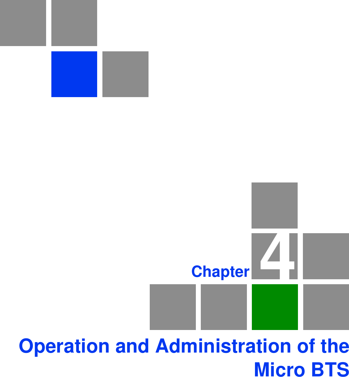
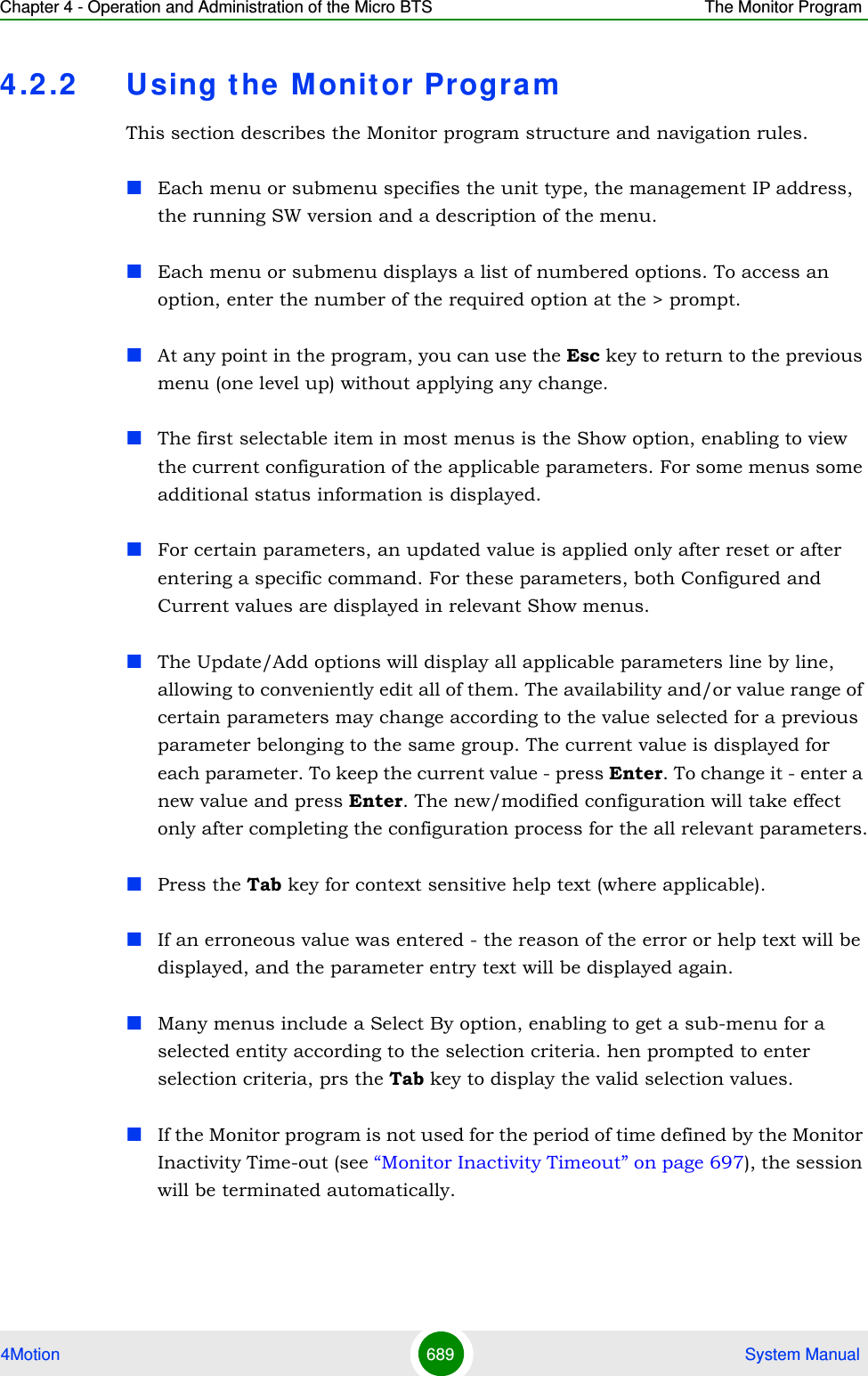
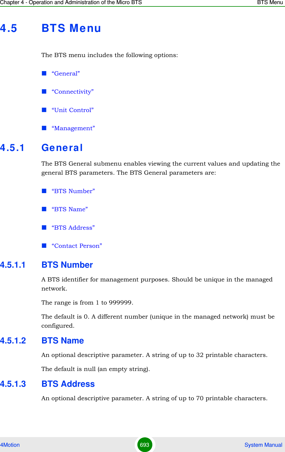
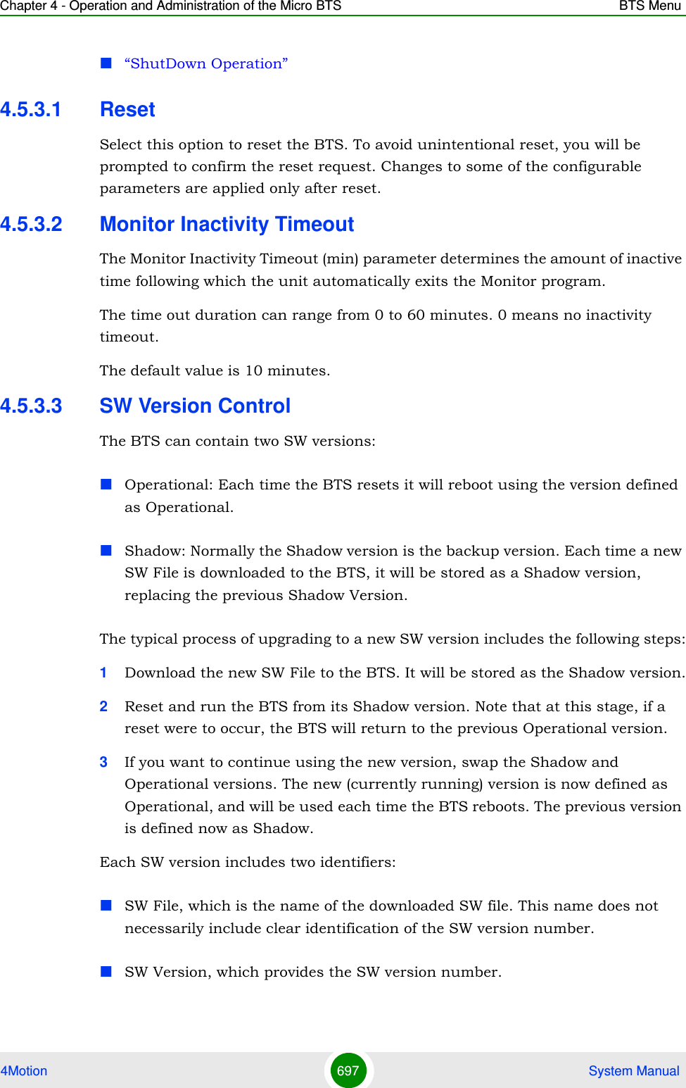
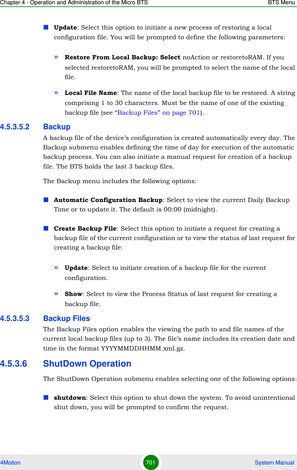
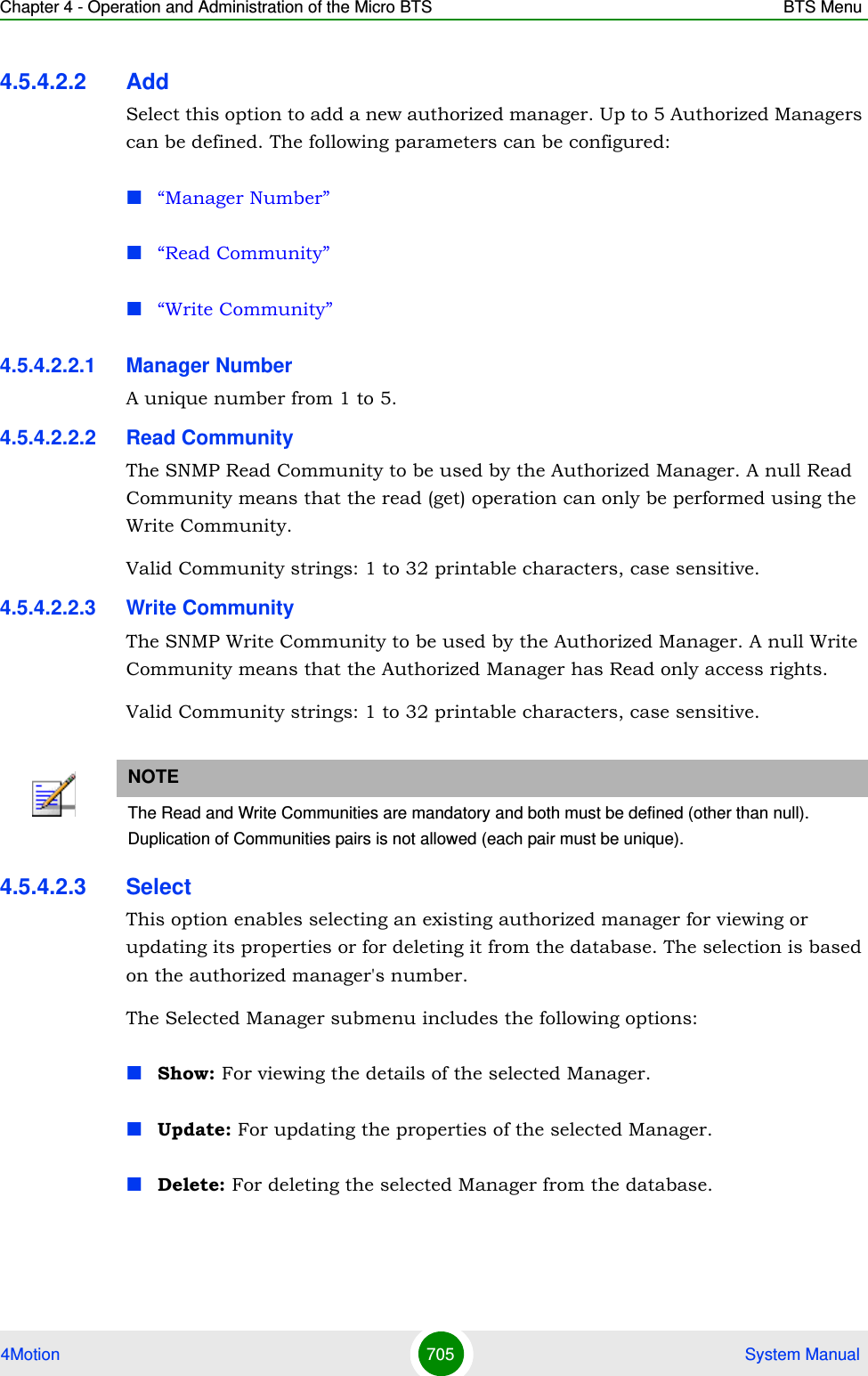
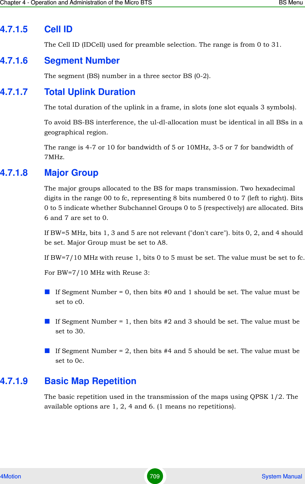
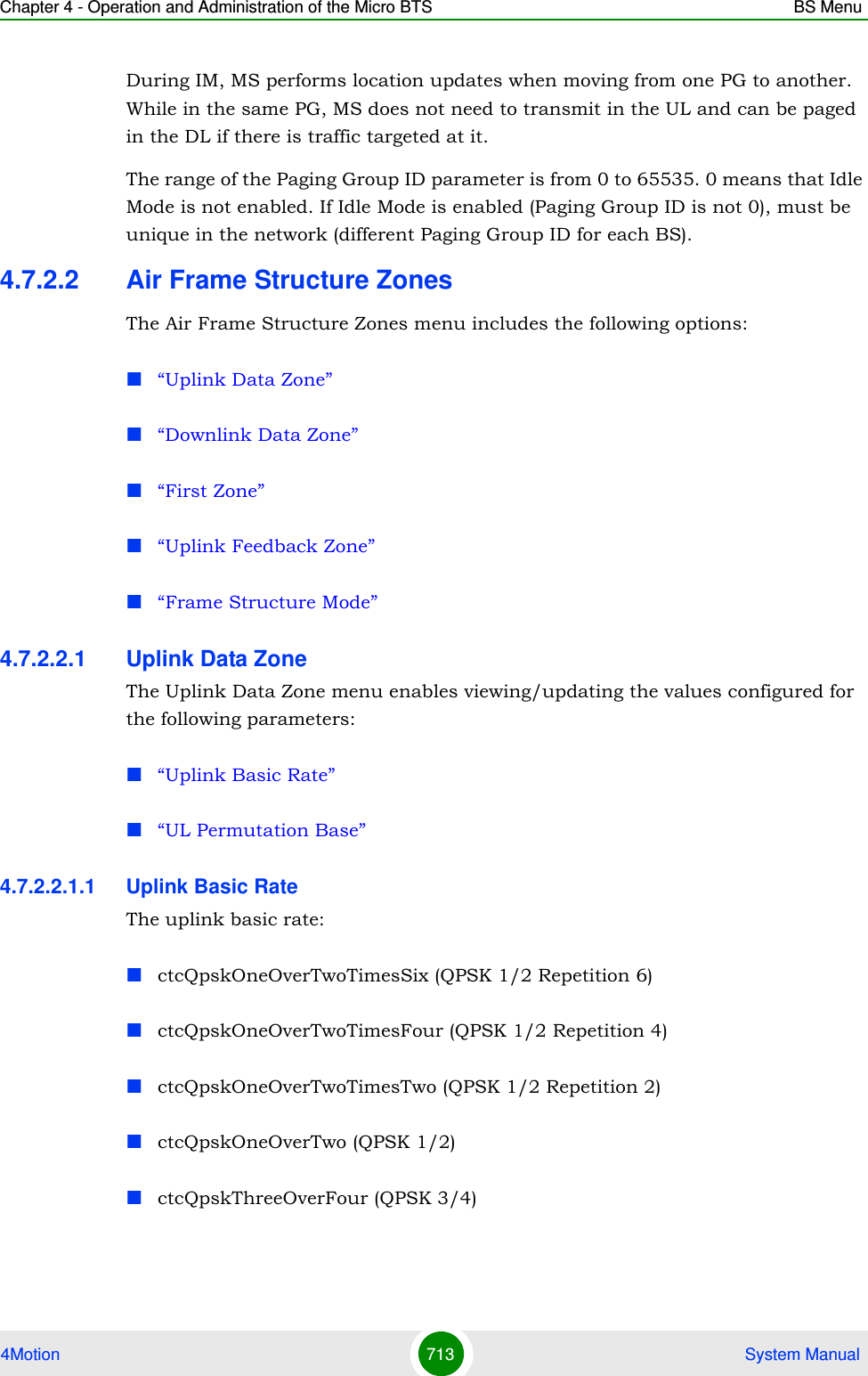
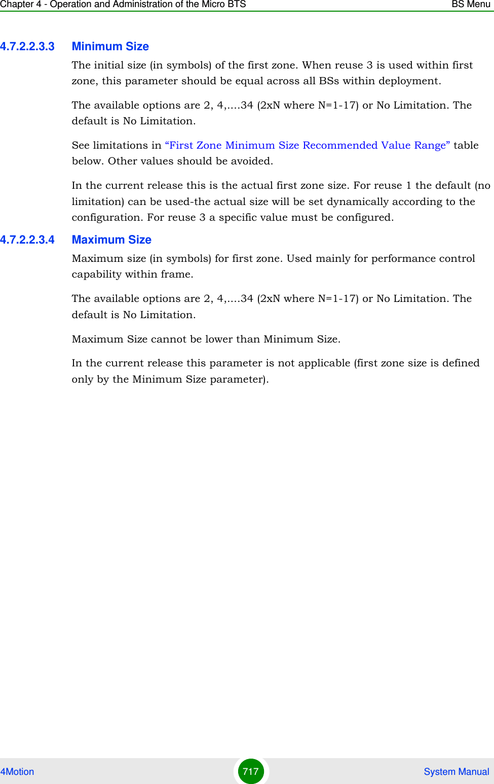
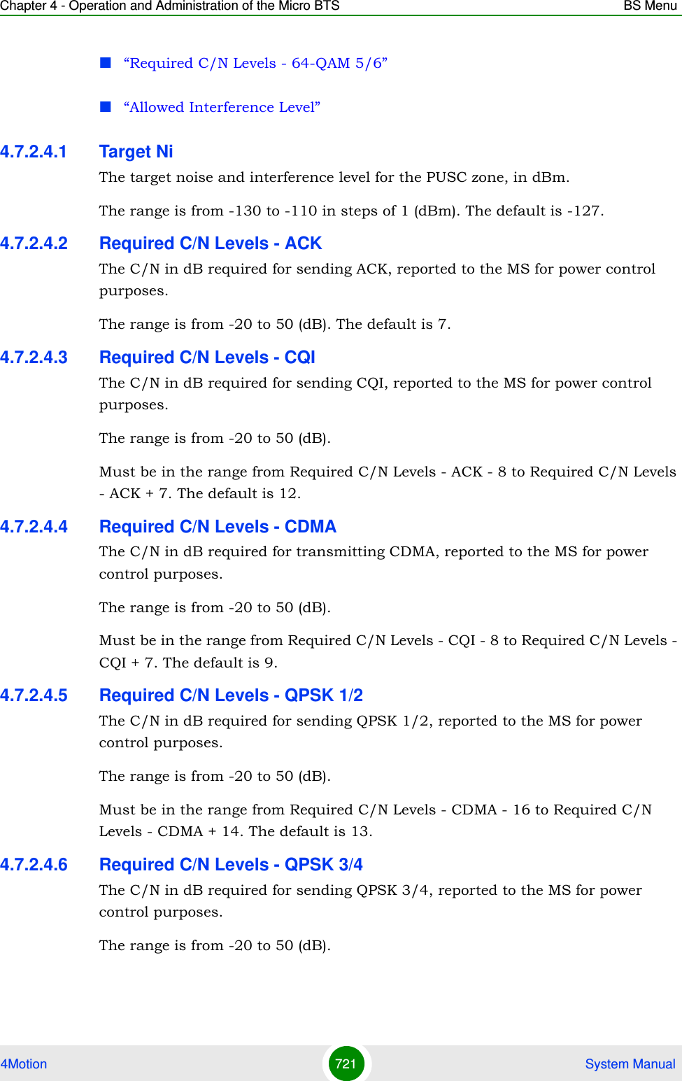
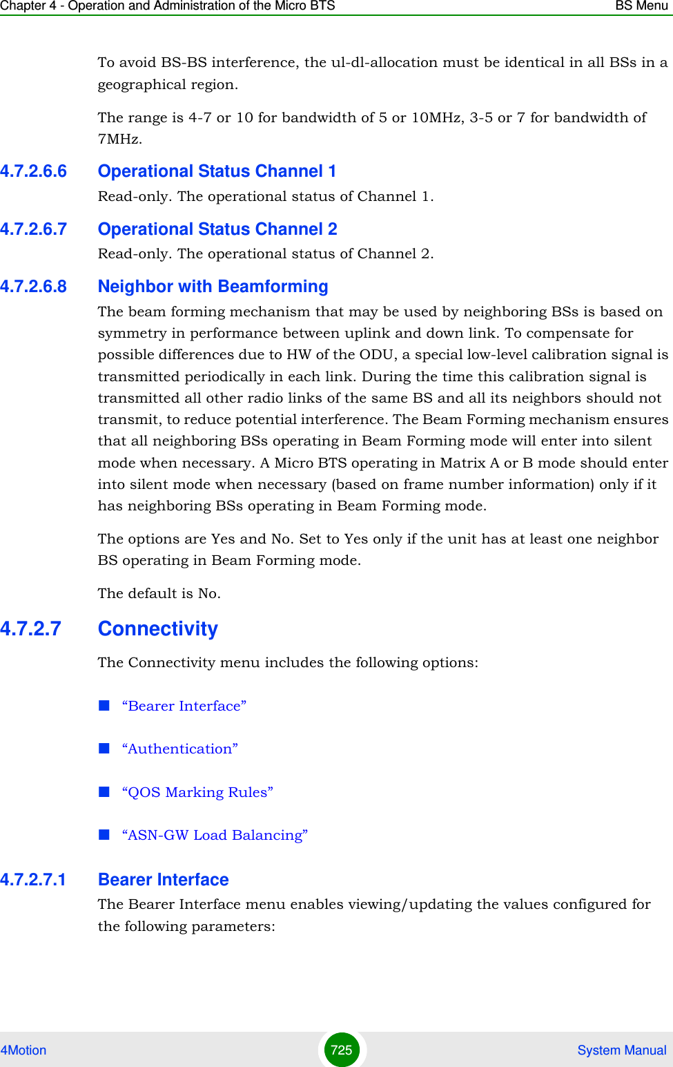
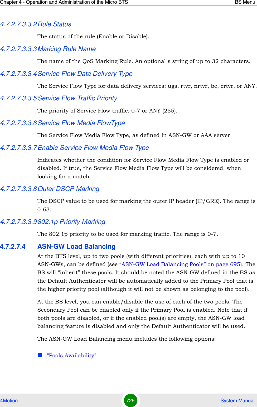
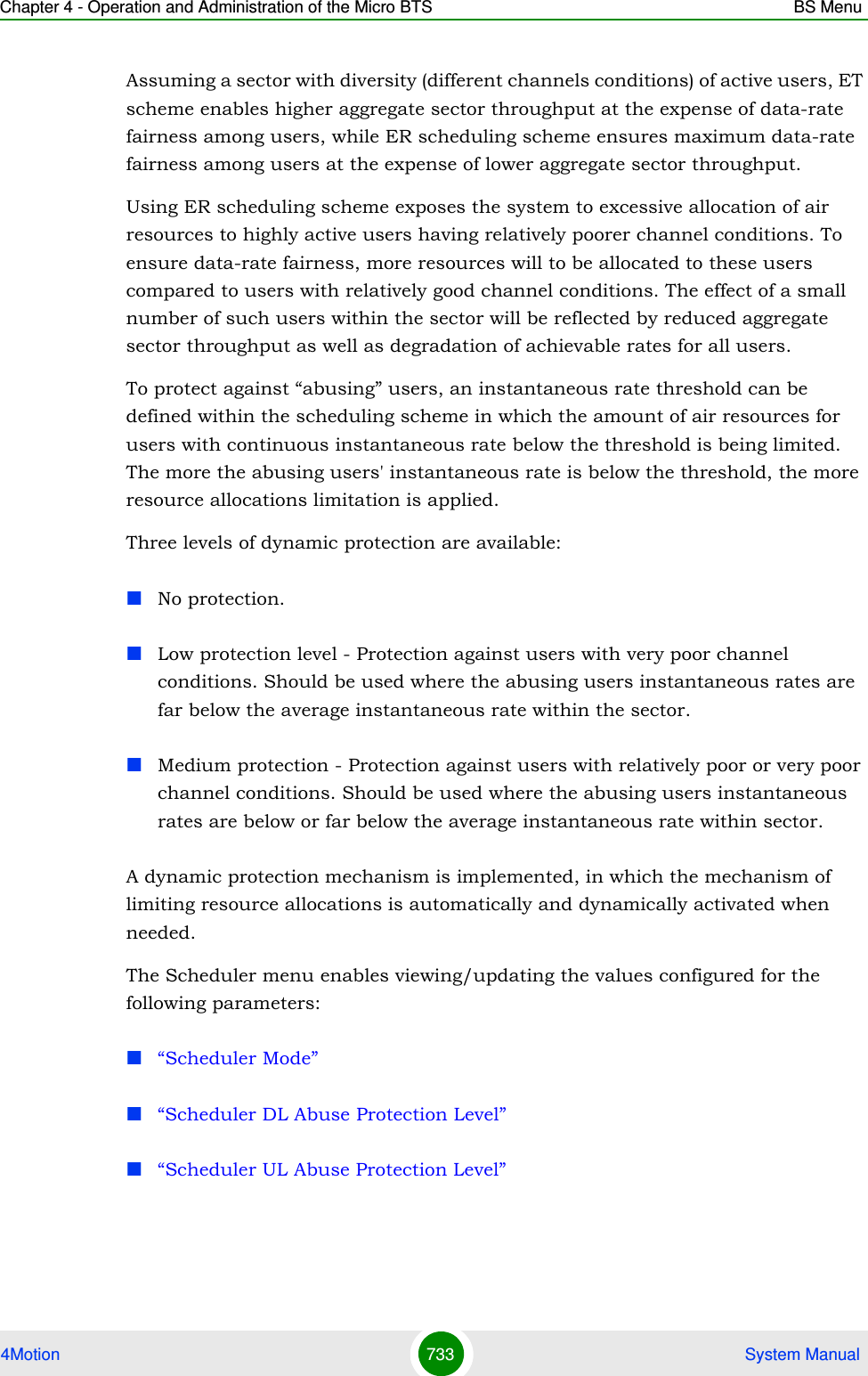
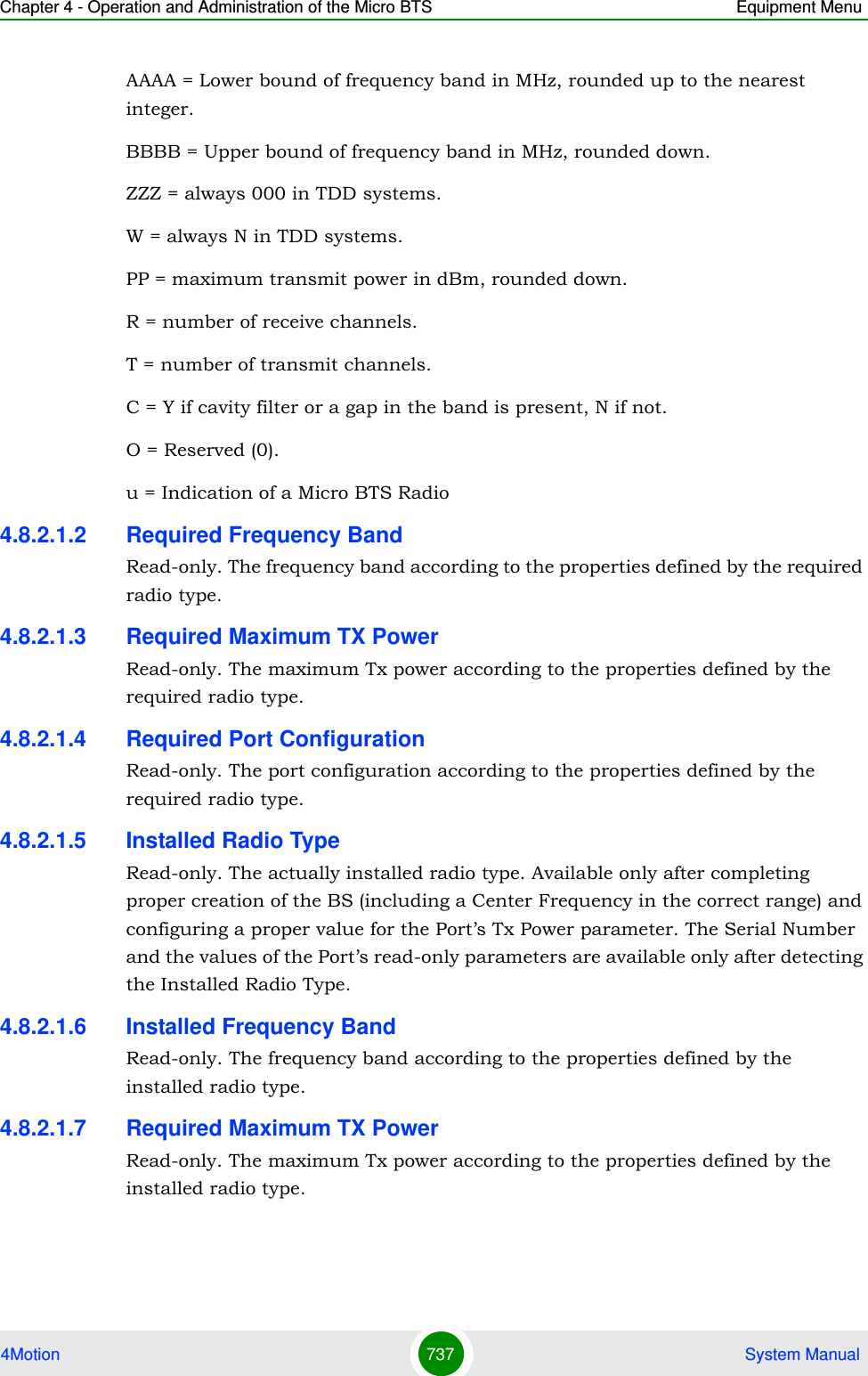
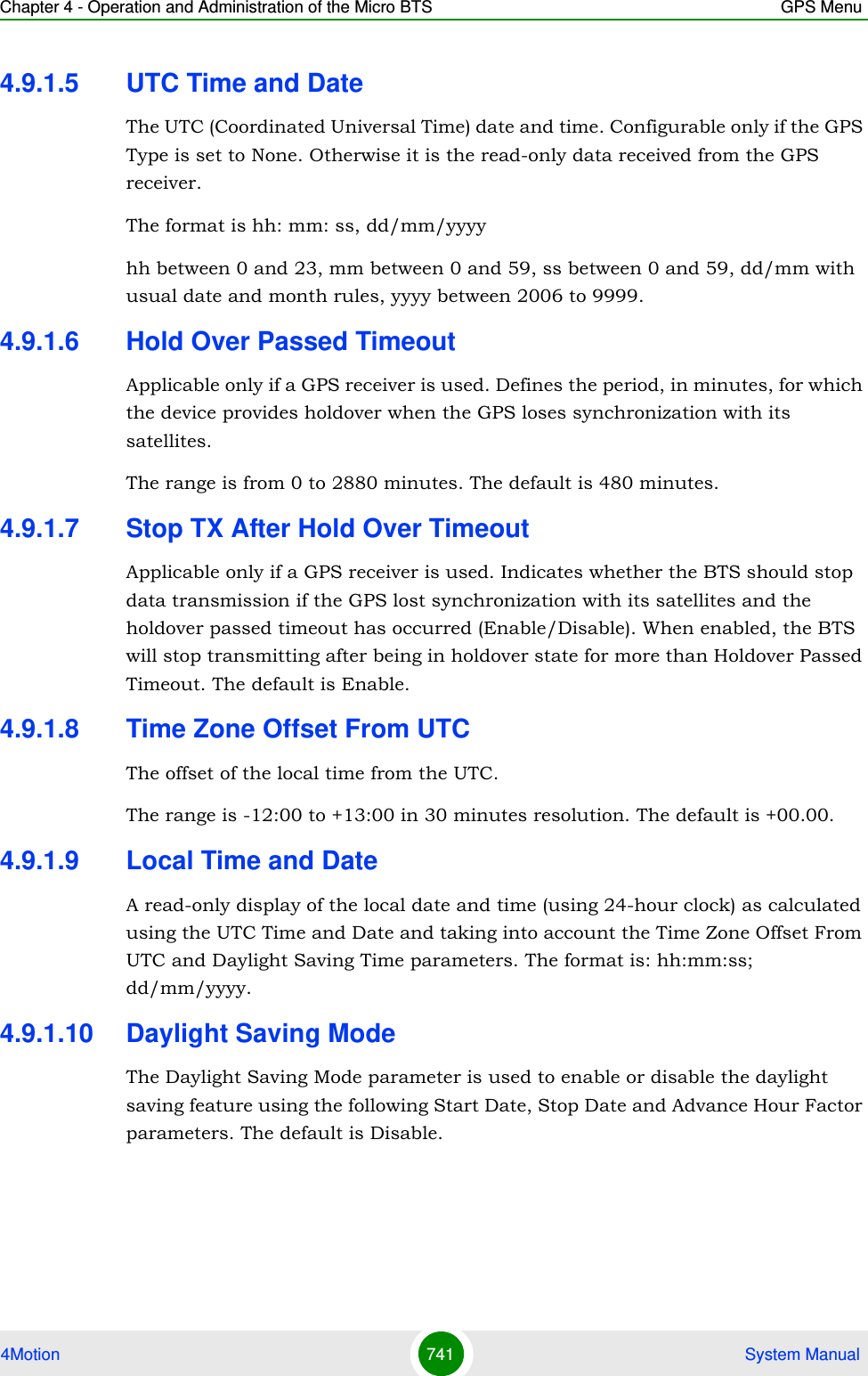
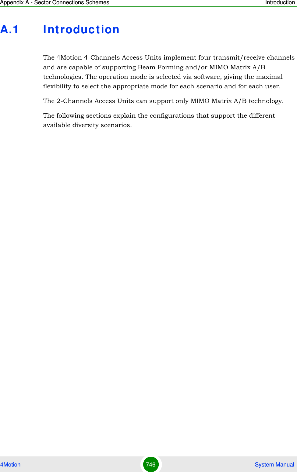
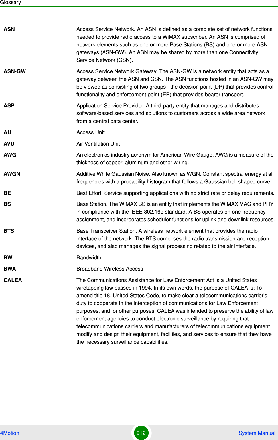
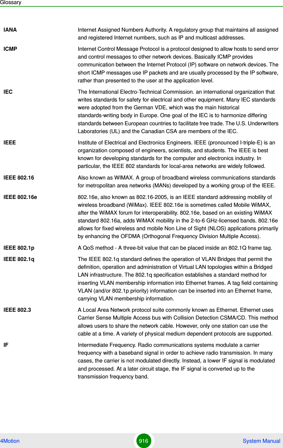
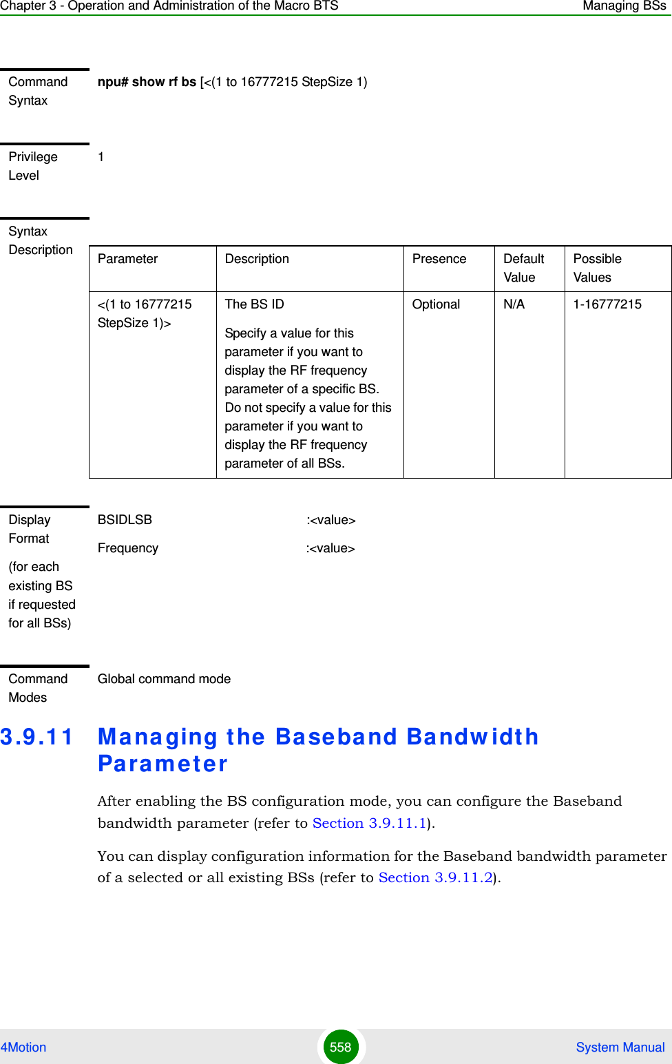
![Chapter 3 - Operation and Administration of the Macro BTS Managing BSs4Motion 549 System Manualnpu# show nbr-requiredcnr bsCommand Syntaxnpu# show nbr-requiredcnr bs [<(1 to 16777215 StepSize 1)> bs-id-lsb <(1 to 16777215 StepSize 1)> ]Privilege Level1Syntax Description Parameter Description Presence Default ValuePossible Values<(1 to 16777215 StepSize 1)>The BS ID Specify a value for this parameter if you want to display the Required C/N Level parameters of a specific Neighbor BS in a specific BS. Do not specify a value for this parameter if you want to display the Required C/N Level parameters of all Neighbor BSs in all BSs.Optional N/A 1-16777215bs-id-lsb <(1 to 16777215 StepSize 1)> The Neighbor BS ID.Specify a value for this parameter if you want to display the Required C/N Level parameters of a specific Neighbor BS in a specific BS. Do not specify a value for this parameter if you want to display the Required C/N Level parameters of all Neighbor BSs in all BSs.Optional N/A 1-16777215](https://usermanual.wiki/Alvarion-Technologies/MICRO-25.Manual-p5/User-Guide-1329246-Page-2.png)
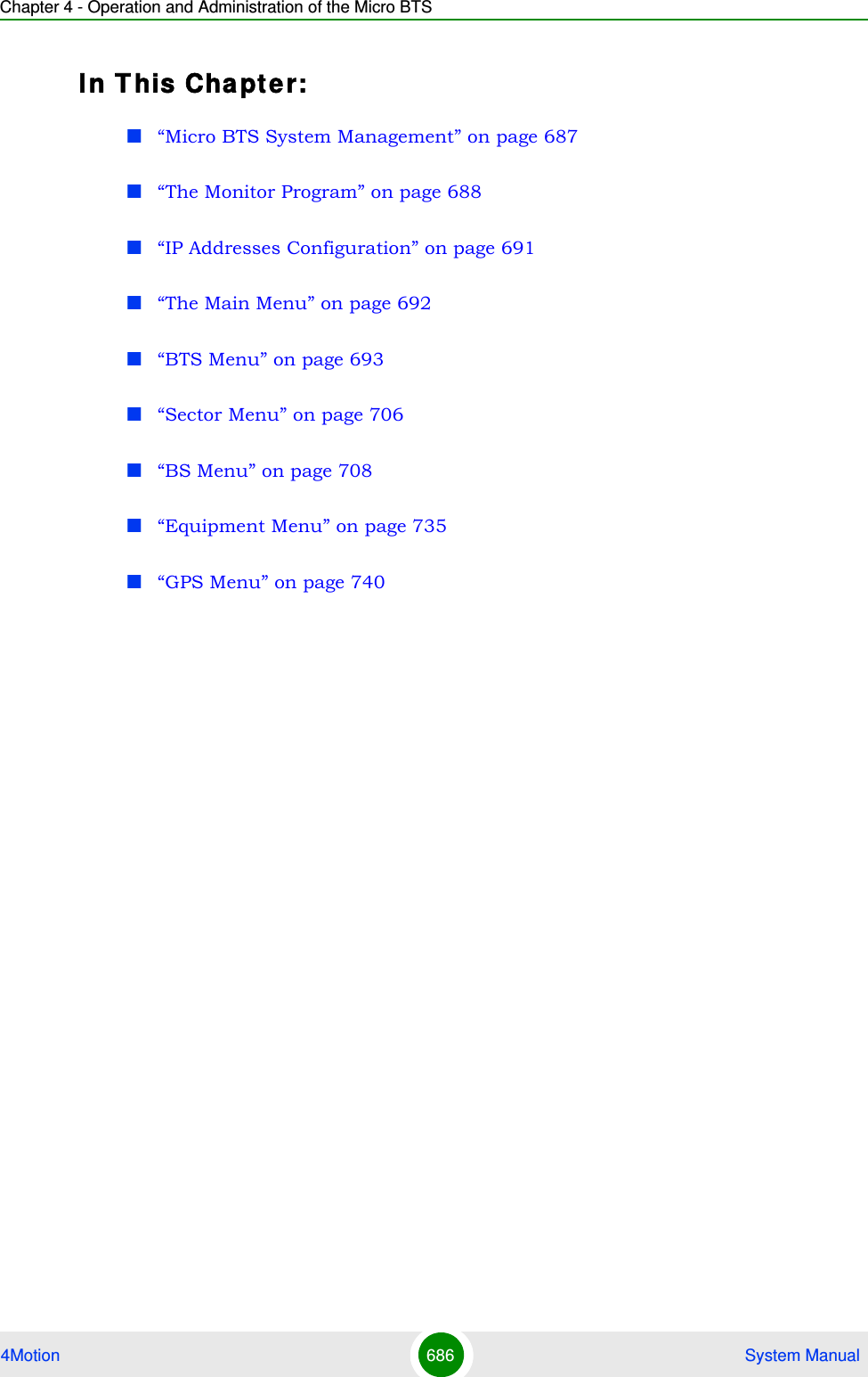
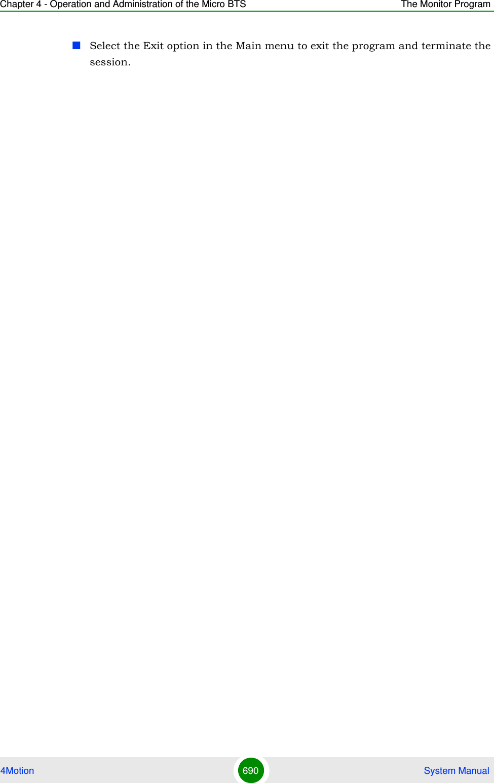
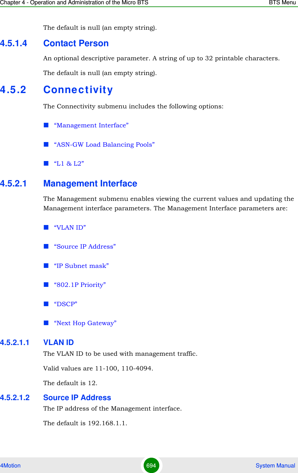
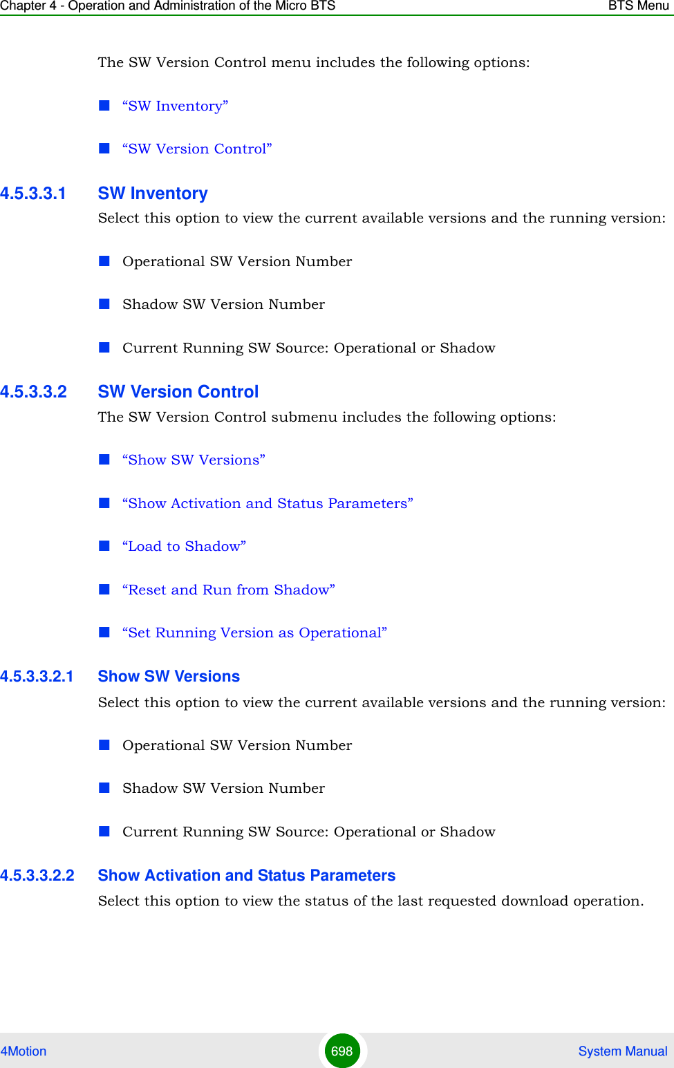
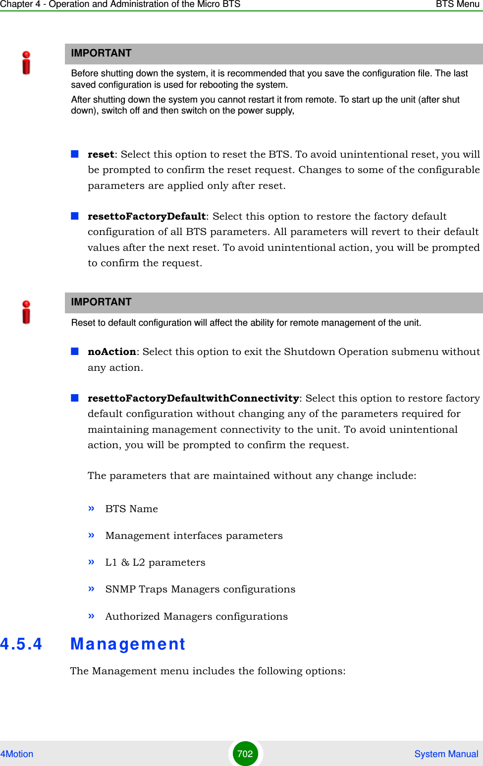
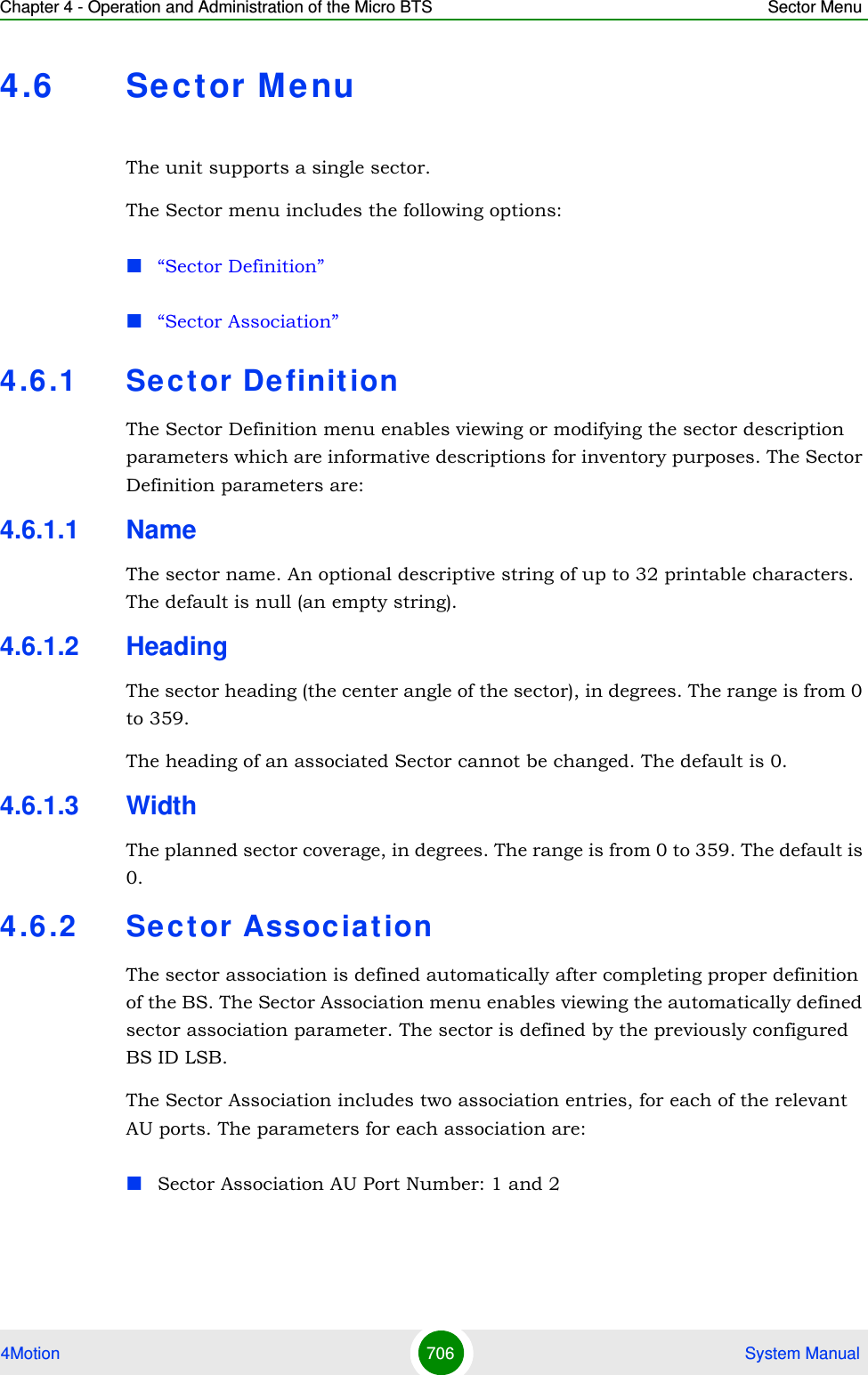
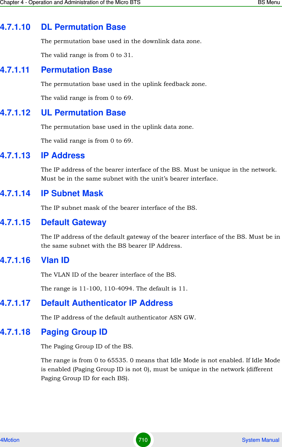
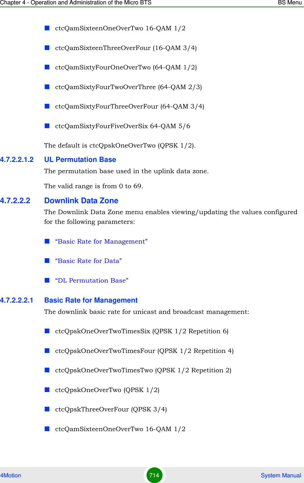
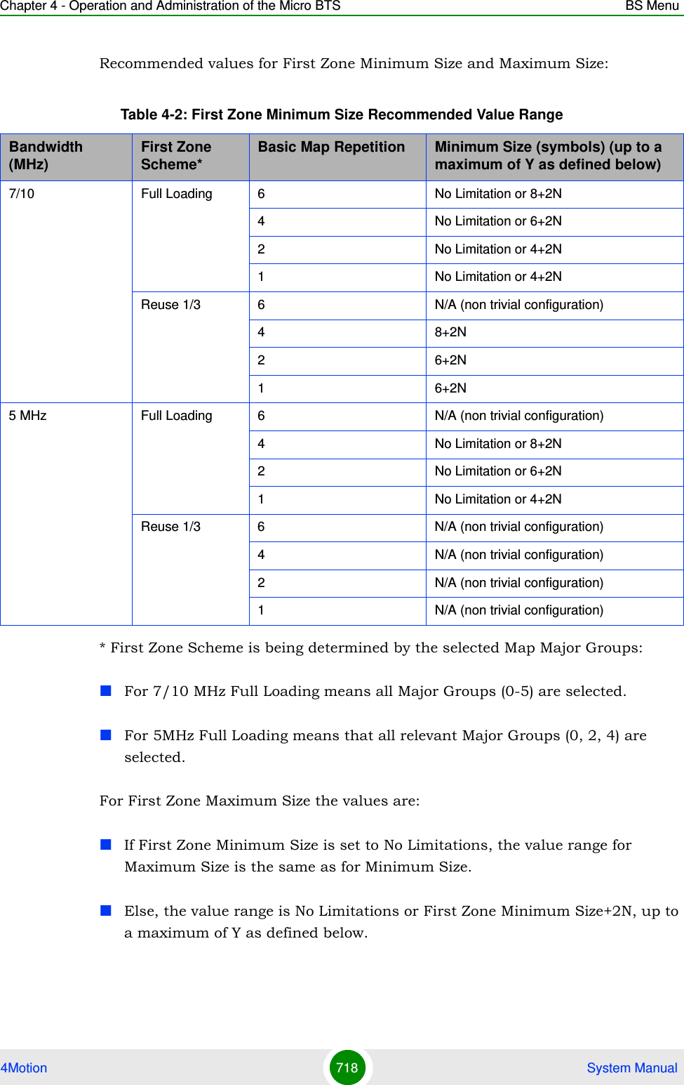
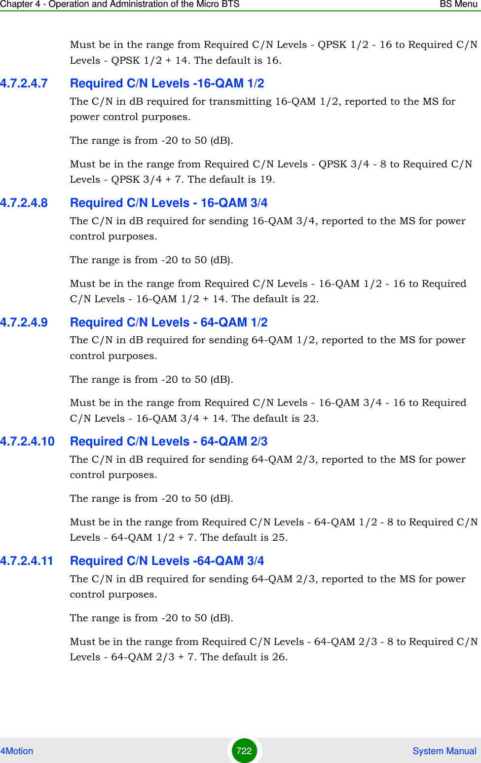
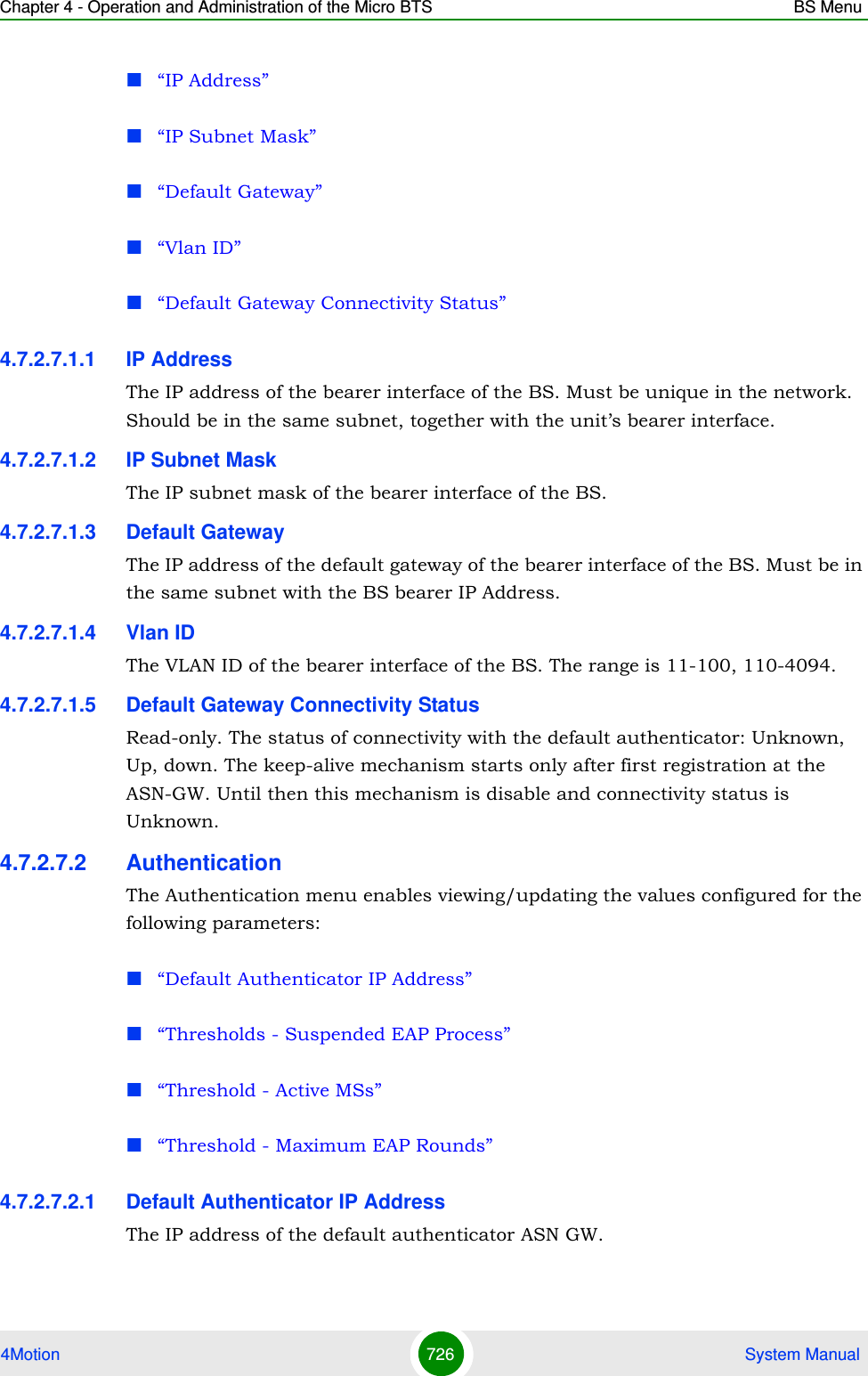
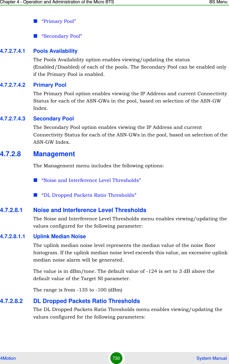
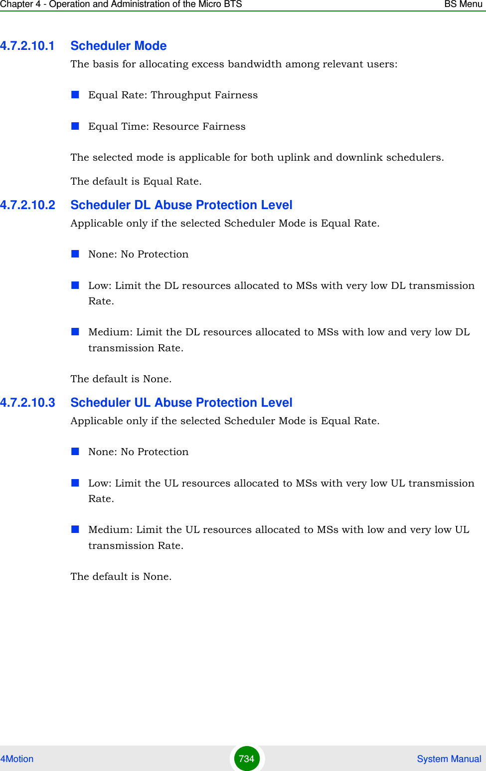
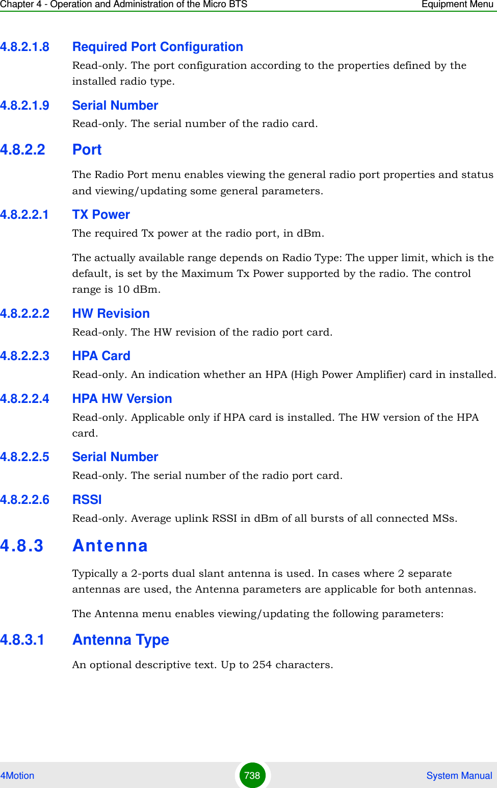
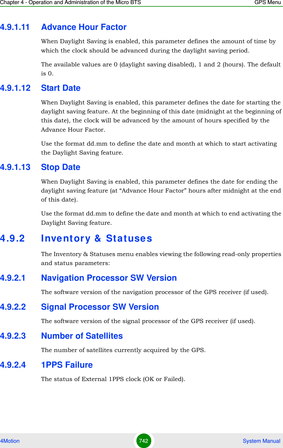
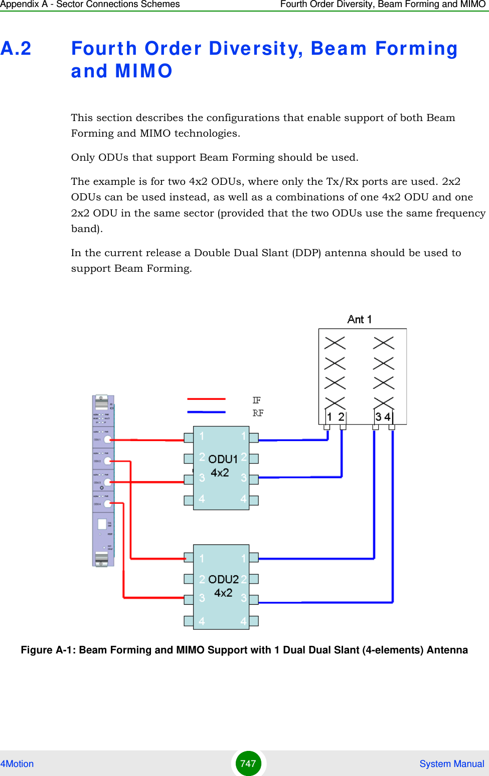
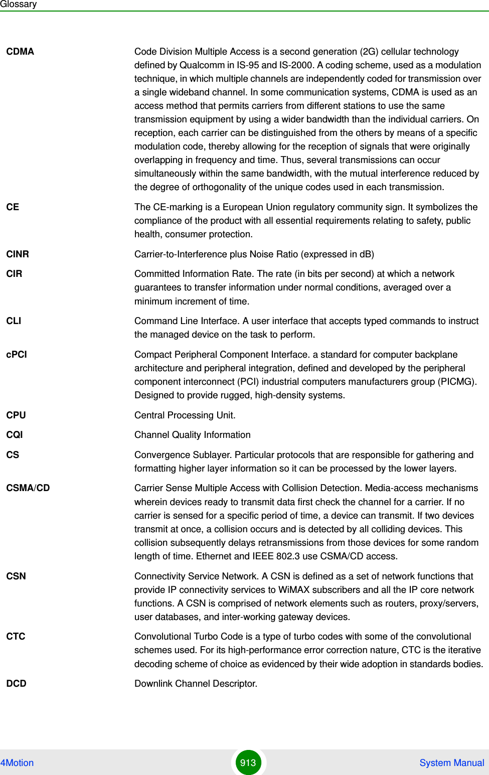
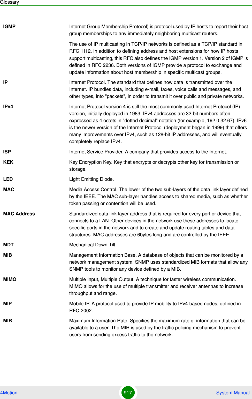
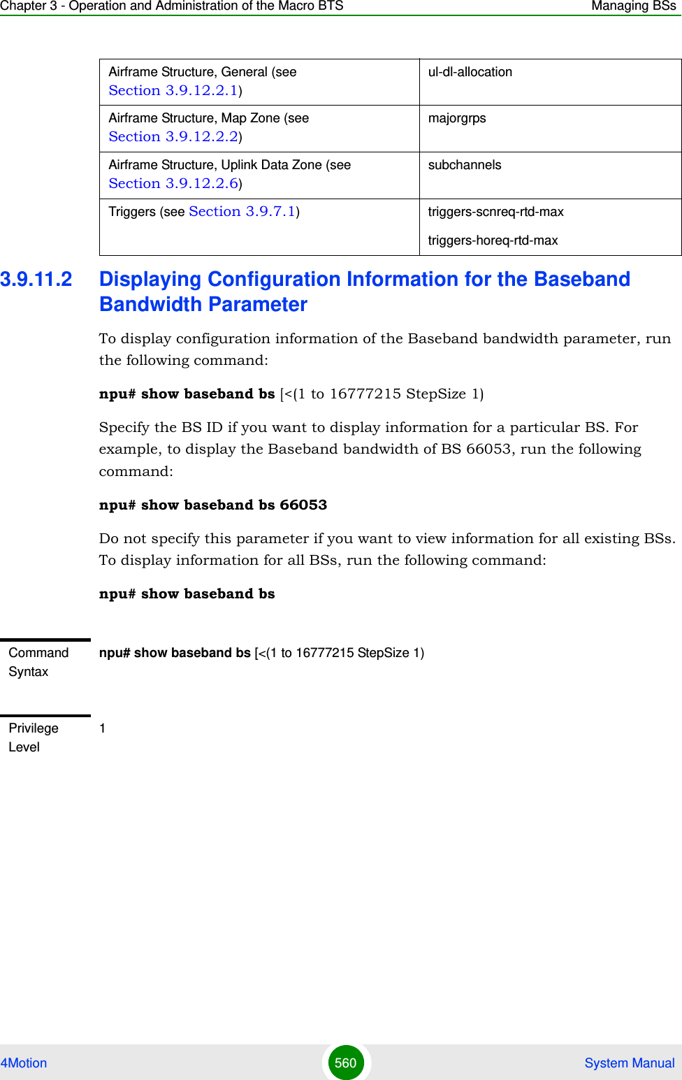
![Chapter 3 - Operation and Administration of the Macro BTS Managing BSs4Motion 550 System Manual3.9.9.7.3 Displaying Configuration Information for Neighbor BS Triggers ParametersTo display configuration information for Neighbor BS Triggers parameters, run the following command:npu# show nbr-triggers bs [<(1 to 16777215 StepSize 1)> bs-id-lsb <(1 to 16777215 StepSize 1)> TrigName {scnReqCinrMin | scnReqRssiMin | scnReqRtdMax | scnRepCinrMaxNbs | scnRepRssiMaxNbs | scnRepCinrMargin | scnRepRssiMargin | scnRepRtdMax | scnRepCinrMinSbs | scnRepRssiMinSbs | hoReqCinrMaxNbs | hoReqRssiMaxNbs | hoReqCinrMargin | hoReqRssiMargin | hoReqRtdMax | hoReqCinrMinSbs | hoReqRssiMinSbs}]Specify the BS ID, Neighbor BS ID (bs-id-lsb) and Trigger name if you want to display configuration for a particular Trigger. For example, to display the scnReqCinrMin parameters of BS Neighbor 68000 in BS 66053, run the following command:npu# show nbr-triggers bs 66053 bs-id-lsb 68000 TrigName scnReqCinrMinDisplay Format(for each existing Neighbor BS in each of the existing BSs if requested for all)BSIDLSB :<value>NeighborBSIDLSB :<value>RequiredCNRforACK :<value>RequiredCNRforCQI :<value>RequiredCNRforCDMA :<value>RequiredCNRforQPSK1/2 :<value>RequiredCNRforQPSK3/4 :<value>RequiredCNRfor16QAM1/2 :<value>RequiredCNRfor16QAM3/4 :<value>RequiredCNRfor64QAM1/2 :<value>RequiredCNRfor64QAM2/3 :<value>RequiredCNRfor64QAM3/4 :<value>RequiredCNRfor64QAM5/6 :<value>Command ModesGlobal command mode](https://usermanual.wiki/Alvarion-Technologies/MICRO-25.Manual-p5/User-Guide-1329246-Page-3.png)
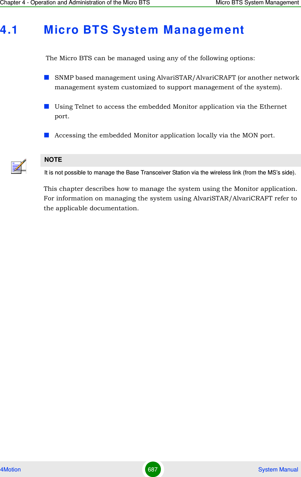
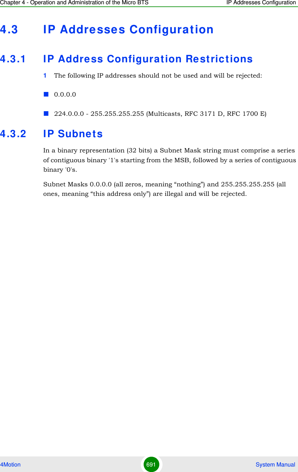
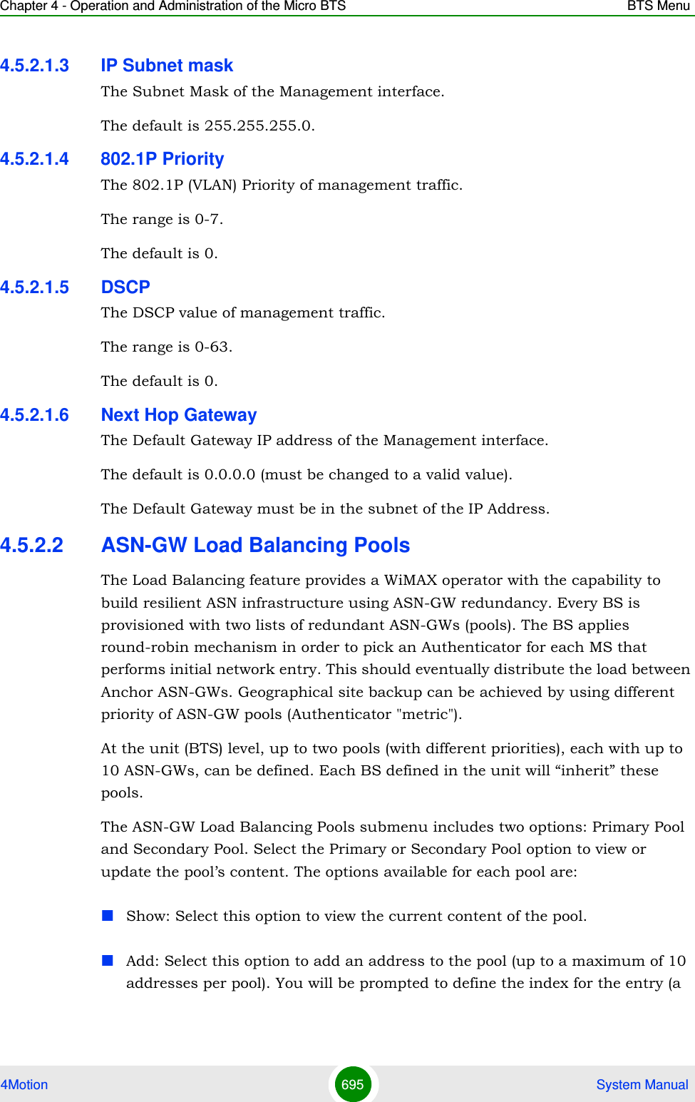
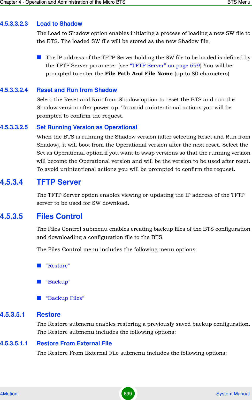
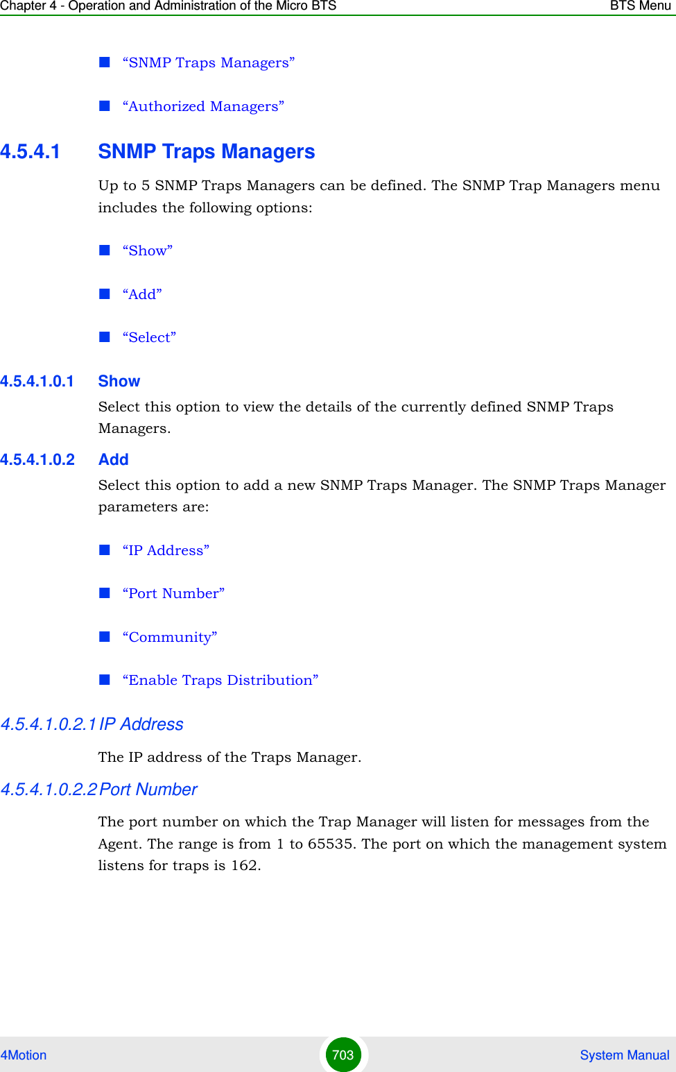
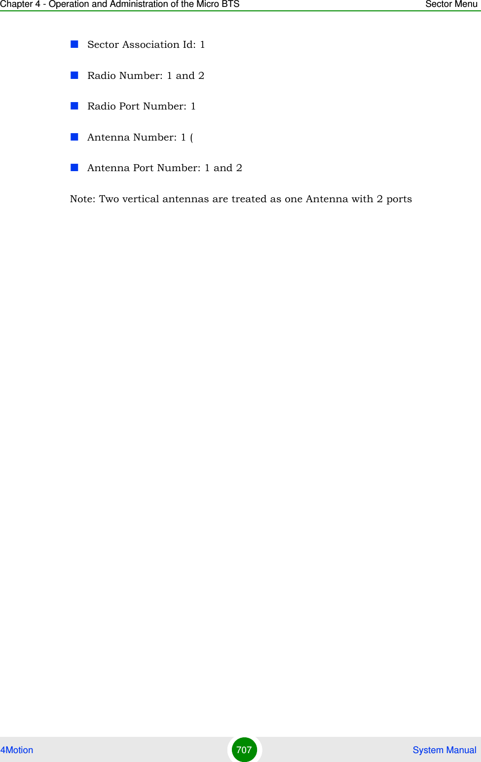
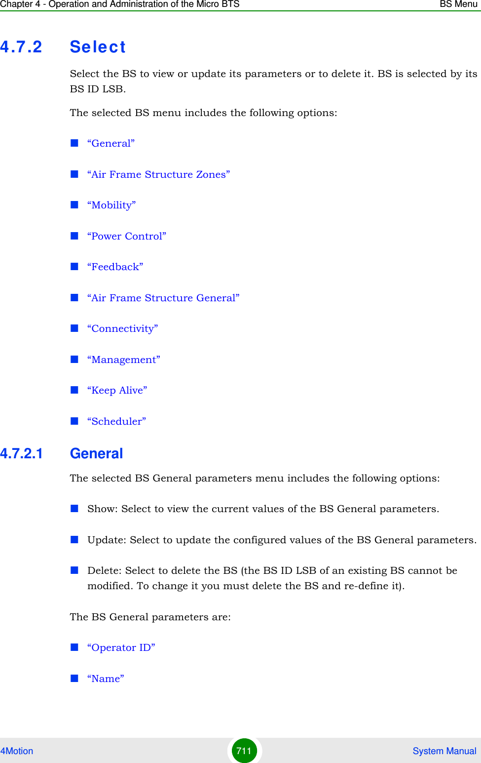
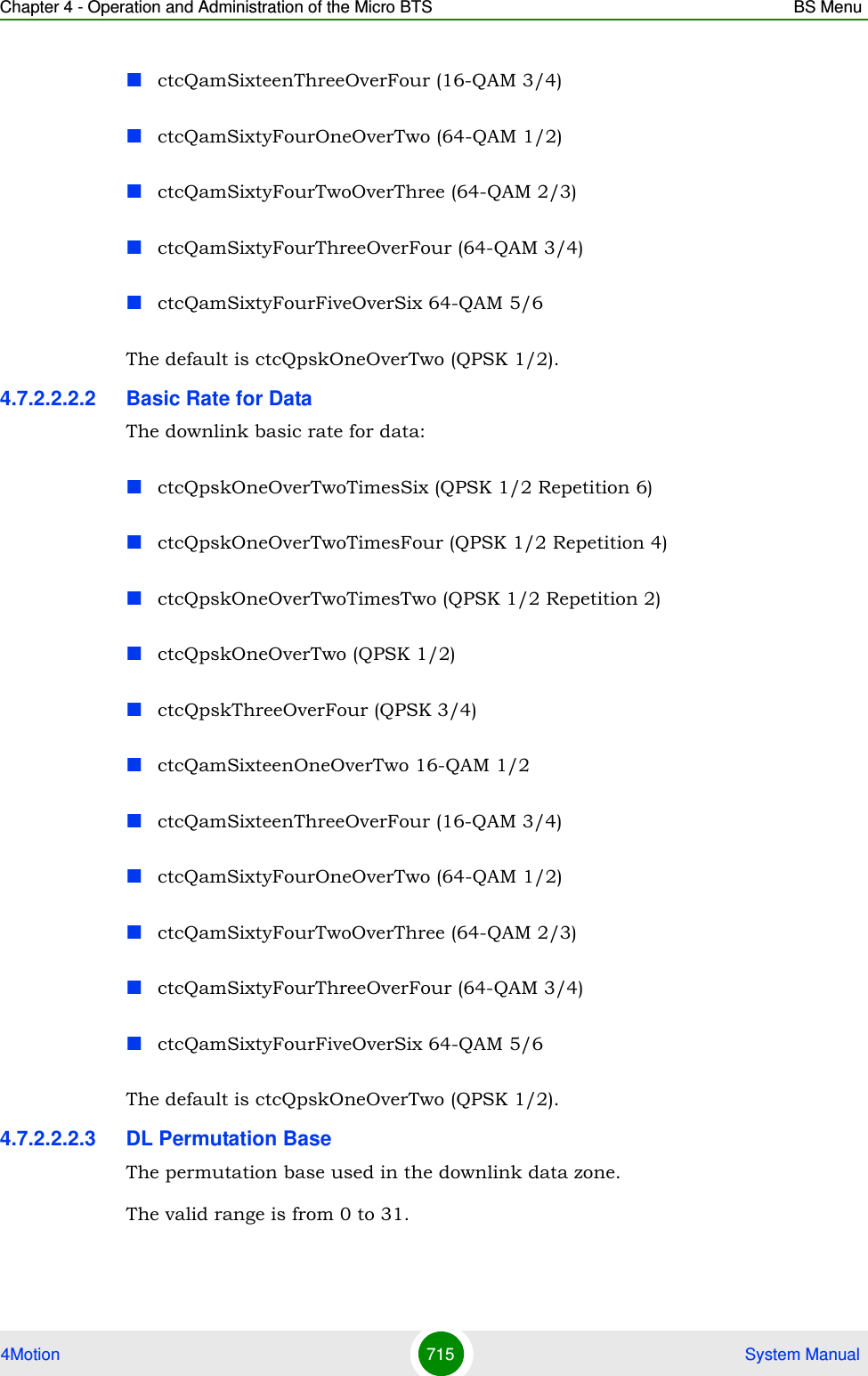
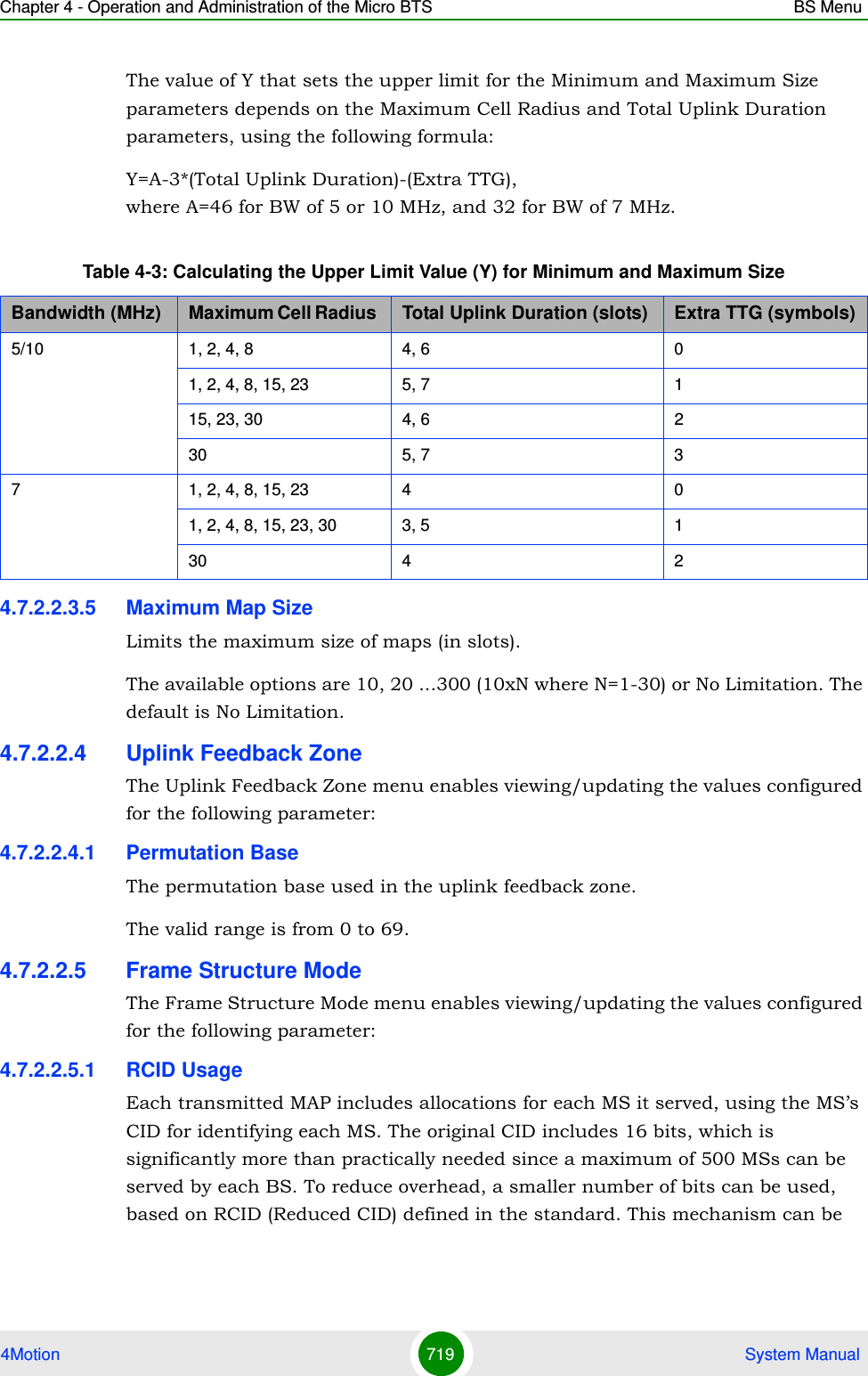
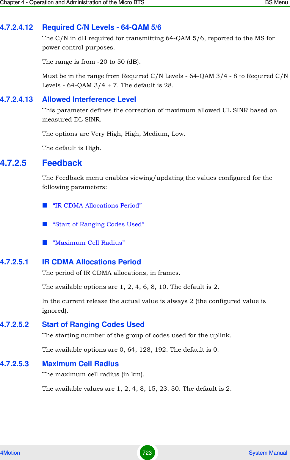
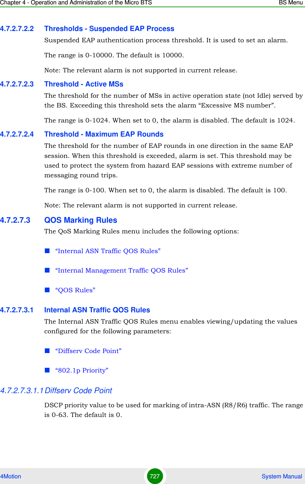
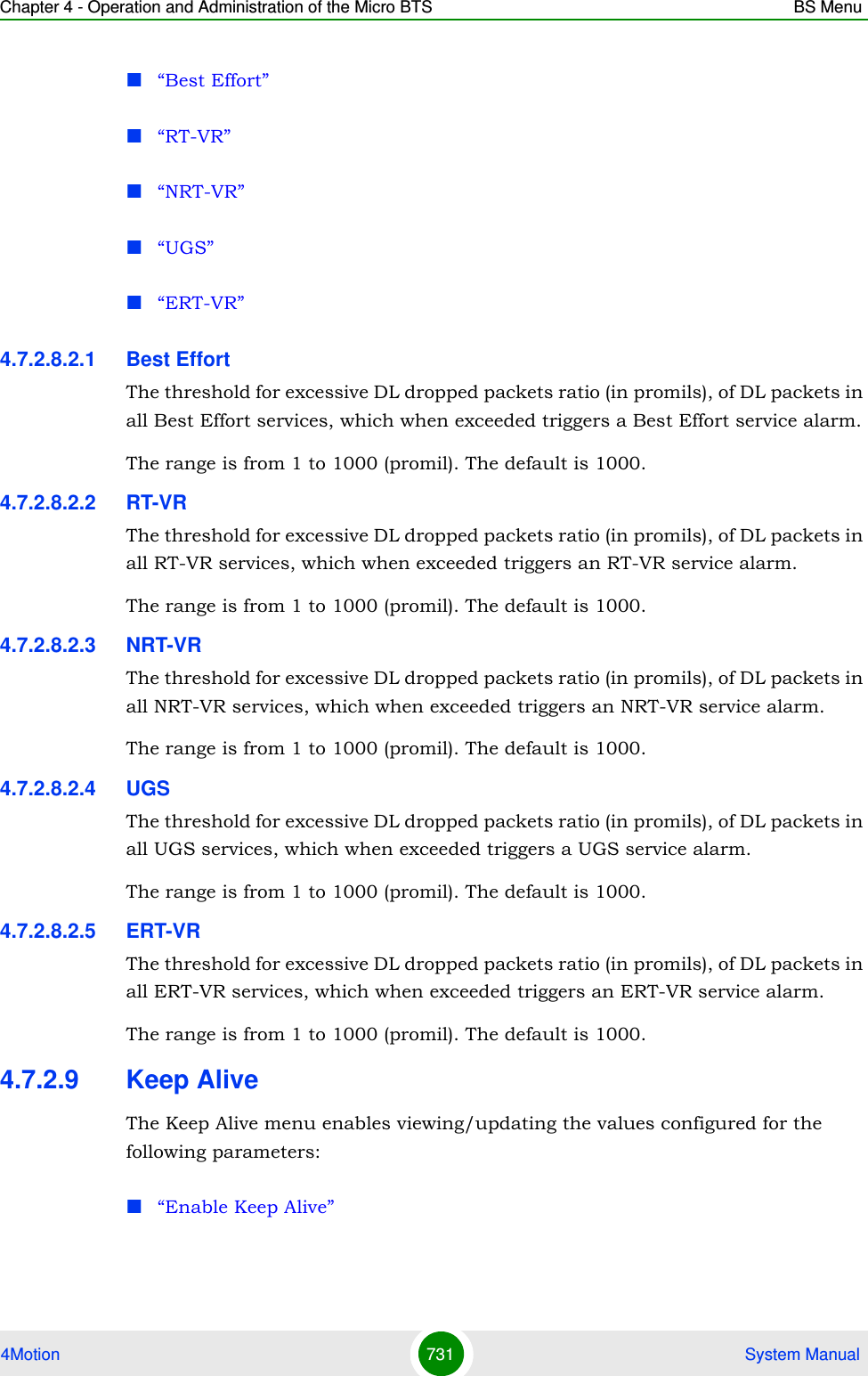
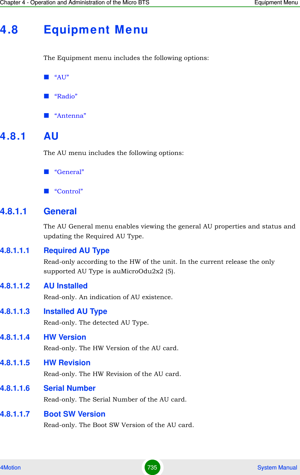
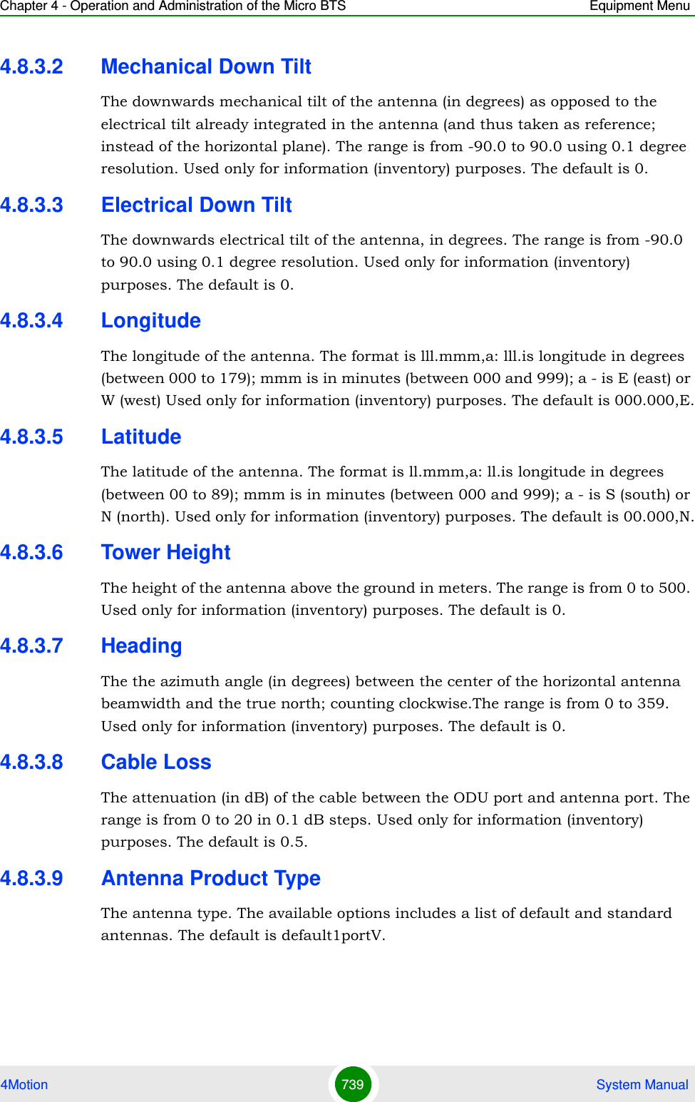
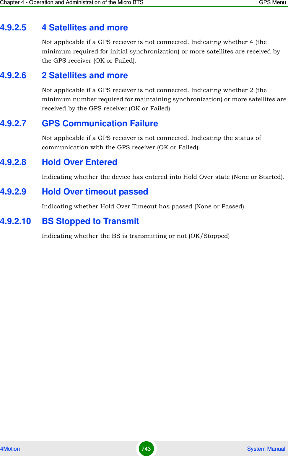
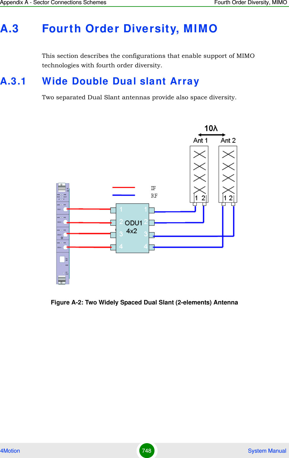
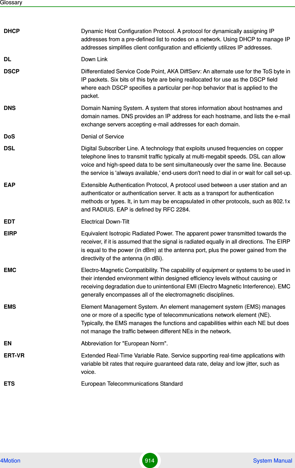
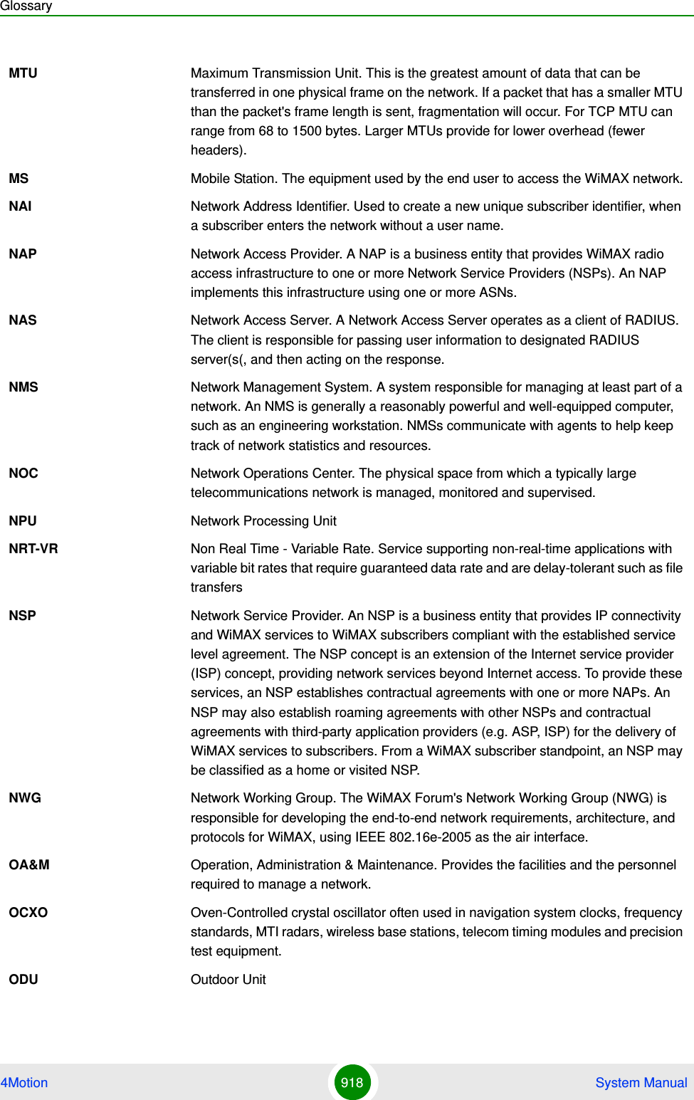
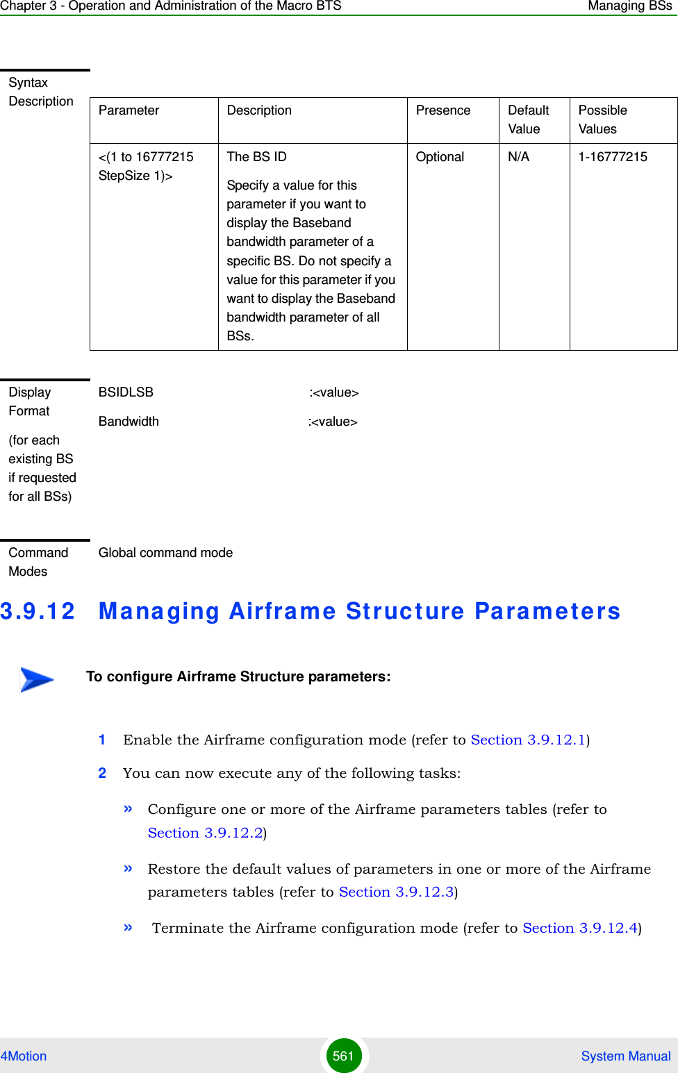
![Chapter 3 - Operation and Administration of the Macro BTS Managing BSs4Motion 551 System ManualDo not specify these parameters if you want to view configuration information for all existing Neighbor BSs in all BSs. To display information for all Neighbor BSs in all BSs, run the following command:npu# show nbr-triggers bsCommand Syntaxnpu# show nbr-triggers bs [<(1 to 16777215 StepSize 1)> bs-id-lsb <(1 to 16777215 StepSize 1)> TrigName {scnReqCinrMin | scnReqRssiMin | scnReqRtdMax | hoReqCinrMaxNbs | hoReqRssiMaxNbs | hoReqCinrMargin | hoReqRssiMargin | hoReqRtdMax | hoReqCinrMinSbs | hoReqRssiMinSbs} ]Privilege Level1Syntax Description Parameter Description Presence Default ValuePossible Values<(1 to 16777215 StepSize 1)>The BS ID Specify a value for this parameter if you want to display a specific Trigger in a specific Neighbor BS of a specific BS. Do not specify a value for this parameter if you want to display the Triggers of all Neighbor BSs in all BSs.Optional N/A 1-16777215bs-id-lsb <(1 to 16777215 StepSize 1)> The Neighbor BS ID.Specify a value for this parameter if you want to display a specific Trigger in a specific Neighbor BS of a specific BS. Do not specify a value for this parameter if you want to display the Triggers of all Neighbor BSs in all BSs.Optional N/A 1-16777215](https://usermanual.wiki/Alvarion-Technologies/MICRO-25.Manual-p5/User-Guide-1329246-Page-4.png)
![Chapter 3 - Operation and Administration of the Macro BTS Managing BSs4Motion 552 System Manual3.9.9.7.4 Displaying Configuration Information for Neighbor BS Specific BS Triggers ParametersTo display configuration information for Neighbor BS Specific BS Triggers parameters, run the following command:npu# show nbr-specific bs [<(1 to 16777215 StepSize 1)> bs-id-lsb <(1 to 16777215 StepSize 1)> TrigName {hoReqCinrMaxNbs | hoReqRssiMaxNbs | hoReqCinrMargin | hoReqRssiMargin} ]Specify the BS ID, Neighbor BS ID (bs-id-lsb) and Specific BS Trigger name if you want to display configuration for a particular Trigger. For example, to display the hoReqRssiMaxNbs parameters of BS Neighbor 68000 in BS 66053, run the following command:npu# show nbr-specific bs 66053 bs-id-lsb 68000 TrigName hoReqRssiMaxNbsTrigName {scnReqCinrMin | scnReqRssiMin | scnReqRtdMax | hoReqCinrMaxNbs | hoReqRssiMaxNbs | hoReqCinrMargin | hoReqRssiMargin | hoReqRtdMax | hoReqCinrMinSbs | hoReqRssiMinSbs} ]The Trigger name Specify only if you want to display a specific Trigger of a specific Neighbor BS in a specific BS. Do not specify if you want to display all Triggers parameters of all Neighbor BSs in all BSsscnReqCinrMinscnReqRssiMinscnReqRtdMaxhoReqCinrMaxNbshoReqRssiMaxNbshoReqCinrMarginhoReqRssiMarginhoReqRtdMaxhoReqCinrMinSbshoReqRssiMinSbs}Display Format(for a selected Trigger)BSIDLSB :<value>BSIDLSB :value>scnReqCinrMin :value>Command ModesGlobal command mode](https://usermanual.wiki/Alvarion-Technologies/MICRO-25.Manual-p5/User-Guide-1329246-Page-5.png)
![Chapter 3 - Operation and Administration of the Macro BTS Managing BSs4Motion 553 System ManualDo not specify these parameters if you want to view configuration information for all existing Neighbor BSs in all BSs. To display information for all Neighbor BSs in all BSs, run the following command:npu# show nbr-triggers bsCommand Syntaxnpu# show nbr-specific bs [<(1 to 16777215 StepSize 1)> bs-id-lsb <(1 to 16777215 StepSize 1)> TrigName {hoReqCinrMaxNbs | hoReqRssiMaxNbs | hoReqCinrMargin | hoReqRssiMargin} ]Privilege Level1Syntax Description Parameter Description Presence Default ValuePossible Values<(1 to 16777215 StepSize 1)>The BS ID Specify a value for this parameter if you want to display a specific Specific BS Trigger in a specific Neighbor BS of a specific BS. Do not specify a value for this parameter if you want to display the Specific BS Triggers of all Neighbor BSs in all BSs.Optional N/A 1-16777215](https://usermanual.wiki/Alvarion-Technologies/MICRO-25.Manual-p5/User-Guide-1329246-Page-6.png)
![Chapter 3 - Operation and Administration of the Macro BTS Managing BSs4Motion 554 System Manual3.9.9.7.5 Displaying Configuration Information for All Neighbor BS ParametersTo display configuration for the all Neighbor BS parameters, run the following command:npu# show nbr-all bs [<(1 to 16777215 StepSize 1)> bs-id-lsb <(1 to 16777215 StepSize 1)>]bs-id-lsb <(1 to 16777215 StepSize 1)> The Neighbor BS ID.Specify a value for this parameter if you want to display a specific Specific BS Trigger in a specific Neighbor BS of a specific BS. Do not specify a value for this parameter if you want to display the Specific BS Triggers of all Neighbor BSs in all BSs.Optional N/A 1-16777215TrigName {hoReqCinrMaxNbs | hoReqRssiMaxNbs | hoReqCinrMargin | hoReqRssiMargin} ]The Trigger name Specify only if you want to display a specific Specific BS Trigger of a specific Neighbor BS in a specific BS. Do not specify if you want to display all Specific BS Triggers parameters of all Neighbor BSs in all BSs{hoReqCinrMaxNbshoReqRssiMaxNbshoReqCinrMarginhoReqRssiMargin}Display Format(for a selected Trigger)BSIDLSB :<value>BSIDLSB :value>hoReqRssiMaxNbs :value>Command ModesGlobal command mode](https://usermanual.wiki/Alvarion-Technologies/MICRO-25.Manual-p5/User-Guide-1329246-Page-7.png)
![Chapter 3 - Operation and Administration of the Macro BTS Managing BSs4Motion 555 System ManualSpecify the BS ID and the Neighbor BS ID (bs-id-lsb) if you want to display configuration for a particular Neighbor BS in a particular BS. For example, to display all parameters of Neighbor BS 68000 in BS 66503, run the following command:npu# show nbr-all bs 66053 bs-id-lsb 68000Do not specify these parameters if you want to view configuration information for all existing Neighbor BSs in all existing BSs. To display information for all Neighbor BSs in all BSs, run the following command:npu# show nbr-all bsCommand Syntaxnpu# show nbr-all bs [<(1 to 16777215 StepSize 1)> bs-id-lsb <(1 to 16777215 StepSize 1)> ]Privilege Level10Syntax Description Parameter Description Presence Default ValuePossible Values<(1 to 16777215 StepSize 1)>The BS ID Specify a value for this parameter if you want to display the parameters of a specific Neighbor BS in a specific BS. Do not specify a value for this parameter if you want to display the parameters of all Neighbor BSs in all BSs.Optional N/A 1-16777215bs-id-lsb <(1 to 16777215 StepSize 1)> The Neighbor BS ID.Specify a value for this parameter if you want to display the parameters of a specific Neighbor BS in a specific BS. Do not specify a value for this parameter if you want to display the parameters of all Neighbor BSs in all BSs.Optional N/A 1-16777215](https://usermanual.wiki/Alvarion-Technologies/MICRO-25.Manual-p5/User-Guide-1329246-Page-8.png)
![Chapter 3 - Operation and Administration of the Macro BTS Managing BSs4Motion 556 System Manual3.9 .10 Managing the RF Frequency Para m e t e rAfter enabling the BS configuration mode, you can configure the RF frequency parameter (refer to Section 3.9.10.1).You can display configuration information for the RF frequency parameter of a selected or all existing BSs (refer to Section 3.9.10.2).3.9.10.1 Configuring the RF Frequency ParameterFrom the BS configuration mode, run the following command:npu(config-bs-66053)# rf [frequency <(2022.5 to 2217.5 StepSize 0.125) | (2302.5 to 2397.5 StepSize 0.125) | (2487.5 to 2687.5 StepSize 0.125) | (3302.5 to 3397.5 StepSize 0.125) | (3402.5 to 3597.5 StepSize 0.125) | (3602.5 to 3797.5 StepSize 0.125)>]Command ModesGlobal command modeTo configure the RF frequency parameter:Command Syntaxnpu(config-bs-66053)# rf [frequency <((2022.5 to 2217.5 StepSize 0.125) | (2302.5 to 2397.5 StepSize 0.125) | (2487.5 to 2687.5 StepSize 0.125) | (3302.5 to 3397.5 StepSize 0.125) | (3402.5 to 3597.5 StepSize 0.125) | (3602.5 to 3797.5 StepSize 0.125)>]Privilege Level10Syntax Description Parameter Description Presence Default ValuePossible Values](https://usermanual.wiki/Alvarion-Technologies/MICRO-25.Manual-p5/User-Guide-1329246-Page-9.png)
![Chapter 3 - Operation and Administration of the Macro BTS Managing BSs4Motion 557 System Manual3.9.10.2 Displaying Configuration Information for the RF Frequency ParameterTo display configuration information of the RF frequency parameter, run the following command:npu# show rf bs [<(1 to 16777215 StepSize 1)Specify the BS ID if you want to display information for a particular BS. For example, to display the RF frequency of BS 66053, run the following command:npu# show rf bs 66053Do not specify this parameter if you want to view information for all existing BSs. To display information for all BSs, run the following command:npu# show rf bs[frequency <(2022.5 to 2217.5 StepSize 0.125) | (2302.5 to 2397.5 StepSize 0.125) | (2487.5 to 2687.5 StepSize 0.125) | (3302.5 to 3397.5 StepSize 0.125) | (3402.5 to 3597.5 StepSize 0.125) | (3602.5 to 3797.5 StepSize 0.125)>]The center of the frequency band in which the BS will transmit, in MHz.Must be within the valid range of the relevant ODU.The indicated Possible Values are for a bandwidth of fiveMhz. For a different bandwidth, the actually valid values are from f1+1/2BW to f2-1/2BW, where f1 is the lowest frequency of the ODU’s radio band. Note that oDU23052360000N361by1Y0 (16) includes two bands: 2305-2320, 2345-2360 MHz.), f2 is the highest frequency of the ODU’s band, and BW is the configured bandwidth (see “Configuring the Baseband Bandwidth Parameter” on page 559). Mandatory N/A 2022.5 to 2217.5 in steps of 0.1252302.5 to 2397.5 in steps of 0.1252487.5 to 2687.5 in steps of 0.1253302.5 to 3397.5 in steps of 0.1253402.5 to 3597.5 in steps of 0.1253602.5 to 3797.5 in steps of 0.125Command Modesbs configuration modeIMPORTANTWhen creating a new BS, the mandatory frequency parameter must be configured.](https://usermanual.wiki/Alvarion-Technologies/MICRO-25.Manual-p5/User-Guide-1329246-Page-10.png)
![Chapter 3 - Operation and Administration of the Macro BTS Managing BSs4Motion 559 System Manual3.9.11.1 Configuring the Baseband Bandwidth ParameterFrom the BS configuration mode, run the following command:npu(config-bs-66053)# baseband [bandwidth {fiveMHz | tenMHz | sevenMHz}]Note that the valid value ranges (and in some cases also default value) of certain parameters are affected by the value configured for the bandwidth parameter. If you change the bandwidth, verify that these parameters are configured properly:To configure the Baseband bandwidth parameter:IMPORTANTA bandwidth of 7 MHz (sevenMHz) is not applicable for ODUs in the 2.x GHz band.Command Syntaxnpu(config-bs-66053)# baseband [bandwidth {fiveMHz | tenMHz | sevenMHz} ]Privilege Level10Syntax Description Parameter Description Presence Default ValuePossible Values[bandwidth {fiveMHz | tenMHz | sevenMHz} ]BS channel bandwidthMandatory N/A fiveMHztenMHzsevenMHz Command Modesbs configuration modeIMPORTANTWhen creating a new BS, the mandatory frequency parameter must be configured.Table ParametersRF (see Section 3.9.10.1) frequency](https://usermanual.wiki/Alvarion-Technologies/MICRO-25.Manual-p5/User-Guide-1329246-Page-12.png)
![Chapter 3 - Operation and Administration of the Macro BTS Managing BSs4Motion 563 System ManualDownlink Diversity (refer to Section 3.9.12.2.3)Uplink Feedback Zone (refer to Section 3.9.12.2.4)Downlink Data Zone (refer to Section 3.9.12.2.5)Uplink Data Zone (refer to Section 3.9.12.2.6)Mimo (refer to Section 3.9.12.2.7)3.9.12.2.1 Configuring Airframe General ParametersTo configure the Airframe General parameters, run the following command:npu(config-bs-66053-airframe)# general [cell-id <(0 to 31 StepSize 1)>] [preamble-grp <(1 to 2 StepSize 1)>] [segment <(0 to 2 StepSize 1)>] [frame-offset <zero|random>] [ul-duration <(3 to 7 StepSize 1 | 10 to 10 StepSize1)>] [nbr-beam-forming {yes | no} ]Neighbor BS Beam Forming (nbr-beam-forming): Applicable only for unit operating in MIMO Matrix A or B mode. The beam forming mechanism is based on symmetry in performance between uplink and down link. To compensate for possible differences due to HW of the ODU, a special low-level calibration signal is transmitted periodically in each link. During the time this calibration signal is transmitted all other radio links of the same BS and all its neighbors should not transmit, to reduce potential interference. The Beam Forming mechanism ensures that all neighboring BSs operating in Beam Forming mode will enter into silent mode when necessary. A unit operating in Matrix A or B mode should enter into silent mode when necessary (based on frame number information) only if it has neigboring BSs operating in Beam Forming mode.IMPORTANTAfter completing the Airframe configuration, do not forget to execute the apply command before exiting the Airframe configuration mode:npu(config-bs-66053-airframe)# applyIMPORTANTWhen creating a new BS, all mandatory Neighbor BS General parameters must be configured.](https://usermanual.wiki/Alvarion-Technologies/MICRO-25.Manual-p5/User-Guide-1329246-Page-16.png)
![Chapter 3 - Operation and Administration of the Macro BTS Managing BSs4Motion 564 System ManualCommand Syntaxnpu(config-bs-66053-airframe)# general [cell-id <(0 to 31 StepSize 1)> ] [preamble-grp <(1 to 2 StepSize 1)>] [segment <(0 to 2 StepSize 1)> ] [frame-offset <zero|random)> ] [ul-duration <(3 to 7 StepSize 1 | 10 to 10 StepSize1)> ] [nbr-beam-forming {yes | no} ]Privilege Level10Syntax Description Parameter Description Presence Default ValuePossible Values[cell-id <(0 to 31 StepSize 1)> ]The Cell ID (IDCell) used for preamble selection. Mandatory when creating a new BS.N/A 0 - 31[preamble-grp <(1 to 2 StepSize 1)>]The preamble group. A value of 2 is available only for the following combinations of segment and cell-id values:segment=0, cell-id=0, 3, 6, 9, 12, 15.segment=1, cell-id=1, 4, 7, 10, 13, 16.segment=2, cell-id=2, 5, 8, 11, 14, 17.Optional 1 1 - 2[segment <(0 to 2 StepSize 1)> ]The segment (BS) number in a three sector BS (0-2). This number influences the preamble selection and the major group used for the FDC transmission.Mandatory when creating a new BS.N/A 0 - 2[frame-offset <zero|random> ]Controls the offset applied between the internal frame count and the reported frame number. If random is selected, the AU will choose a random number between 0 to 15.Mandatory when creating a new BS.zero zero (0)random](https://usermanual.wiki/Alvarion-Technologies/MICRO-25.Manual-p5/User-Guide-1329246-Page-17.png)
![Chapter 3 - Operation and Administration of the Macro BTS Managing BSs4Motion 565 System Manual3.9.12.2.2 Configuring Airframe Map Zone ParametersTo configure the Airframe Map Zone parameters, run the following command:npu(config-bs-66053-airframe)# mapzone [size <(-1 to -1 StepSize 1) | (2 to 16 StepSize 2)>] [majorgrps <hex-string>] [repetition <(1 to 1 StepSize 1) | (2 to 6 StepSize 2)>] [RCID-Usage {enable | disable} ]Each transmitted MAP includes allocations for each MS it served, using the MS’s CID for identifying each MS. The original CID includes 16 bits, which is significantly more than practically needed since a maximum of 500 MSs can be served by each BS. To reduce overhead, a smaller number of bits can be used, based on RCID (Reduced CID) defined in the standard. This mechanism can be used only if all MSs served by the BS support RCID. When enabled, CIDs of either 7 or 11 bits will be dynamically used, according to the current number of MS served at each given moment.[ul-duration <(3 to 7 StepSize 1 | 10 to 10 StepSize1)> ]The total duration of the uplink in a frame, in slots. (one slot equals 3 symbols).The range is 4-7 or 10 for bandwidth = 5 or 10MHz, 3-5 or 7 for bandwidth = 7MHz. To avoid BS-BS interference, the ul-duration must be identical in all BSs in a geographical region.Mandatory when creating a new BS.N/A 3 - 7, 10[nbr-beam-forming {yes | no} ]Applicable only for BSs using MIMO MatrixAorB mode. Indicates whether any of the neighboring BSs operates in beamForming mode.Optional no yesnoCommand Modesbs airframe configuration mode IMPORTANTWhen creating a new BS, the mandatory Airframe Map Zone majorgrps parameter must be configured.](https://usermanual.wiki/Alvarion-Technologies/MICRO-25.Manual-p5/User-Guide-1329246-Page-18.png)
![Chapter 3 - Operation and Administration of the Macro BTS Managing BSs4Motion 566 System ManualCommand Syntaxnpu(config-bs-66053-airframe)# mapzone [size <(-1 to -1 StepSize 1) | (2 to 16 StepSize 2)> ] [majorgrps <hex-string>] [repetition <(1 to 1 StepSize 1) | (2 to 6 StepSize 2)> ] [RCID-Usage {enable | disable} ]Privilege Level10Syntax Description Parameter Description Presence Default ValuePossible Valuessize <(-1 to -1 StepSize 1) | (2 to 16 StepSize 2)>The map zone size in symbols. A value of "-1" means the map zone size will be dynamic.Optional 6 -1, 2, 4, 6, 8, 10, 12, 14, 16.](https://usermanual.wiki/Alvarion-Technologies/MICRO-25.Manual-p5/User-Guide-1329246-Page-19.png)
![Chapter 3 - Operation and Administration of the Macro BTS Managing BSs4Motion 568 System Manual3.9.12.2.3 Configuring the Airframe Downlink Diversity Mode ParameterThe system supports the following operation modes in the downlink:MIMO Matrix A or BBeam FormingIn MIMO Matrix A or B mode the system can use either MIMO Matrix A or Matrix B. The selection between Matrix A and Matrix B is performed automatically for each MS according to link conditions and supported MS capabilities.MIMO Matrix A for Coverage Gain: In configuration with multiple transmit/receive antennas, a single data stream is transmitted in parallel over multiple paths. A mathematical algorithm known as Space Time Codes (STC) is used to encode the data streams to make them orthogonal to each other. This improves the signal to noise ratio at the receiver side, resulting in increased range and better throughput for subscribers that are difficult to reach (e.g. deep indoors).MIMO Matrix B for Increased Capacity: This flavor of MIMO, also known as Spatial Multiplexing MIMO (SM-MIMO), sends an independent data stream over each antenna. Thus, in case signal conditions are good, the data rate is increased and in excellent conditions may be doubled.Beam Forming mode is applicable only for 4x4 configurations (4-channels AU, 2x2 or 4x2 ODUs that support beam forming). The system learns the signals received from each MS in each of the antennas, and adapt the transmitted signals accordingly by sending the same data into radio signals at specific relative phases, Beamforming creates a narrower antenna beam than that generated by a baseline fixed-beam antenna, with the beam acting as a powerful adaptive directional antenna. The signal with its transmitted energy is electronically formed and directed to a particular subscriber, resulting in higher downlink gain for data, greater downlink throughput and lower interference.To configure the Airframe Downlink Diversity mode parameter, run the following command:npu(config-bs-66053-airframe)# dldiversity [mode < matrixAorB | beamForming>]IMPORTANTWhen creating a new BS, the Airframe Downlink Diversity mode parameter must be configured (even if configured to the default value).](https://usermanual.wiki/Alvarion-Technologies/MICRO-25.Manual-p5/User-Guide-1329246-Page-21.png)
![Chapter 3 - Operation and Administration of the Macro BTS Managing BSs4Motion 569 System Manual3.9.12.2.4 Configuring Airframe Uplink Feedback Zone ParameterTo configure the Airframe Uplink Feedback Zone parameter, run the following command:npu(config-bs-66053-airframe)# ulfeedbackzone permbase <(0 to 69 StepSize 1)>Command Syntaxnpu(config-bs-66053-airframe)# dldiveraity [mode <matrixAorB | beamForming>]Privilege Level10Syntax Description Parameter Description Presence Default ValuePossible Valuesmode <matrixAorB |beamForming>The diversity mode used in downlink transmissions.beamForming is not applicable for 2-channels AU.Optional matrixA0rB matrixAorBbeamFormingCommand Modesbs airframe configuration mode IMPORTANTWhen creating a new BS, the Airframe Structure Uplink Feedback Zone mandatory permbase parameter must be configured.Command Syntaxnpu(config-bs-66053-airframe)# ulfeedbackzone permbase <(0 to 69 StepSize 1)>Privilege Level10](https://usermanual.wiki/Alvarion-Technologies/MICRO-25.Manual-p5/User-Guide-1329246-Page-22.png)
![Chapter 3 - Operation and Administration of the Macro BTS Managing BSs4Motion 570 System Manual3.9.12.2.5 Configuring Airframe Downlink Data Zone ParameterTo configure the Airframe Downlink Data Zone parameter, run the following command:npu(config-bs-66053-airframe)# dldatazone permbase <(0 to 31 StepSize 1)>Syntax Description Parameter Description Presence Default ValuePossible Values[permbase <(0 to 69 StepSize 1)> ]The permutation base used in the feedback zoneMandatory when creating a new BS.N/A 0 - 69Command Modesbs airframe configuration mode IMPORTANTWhen creating a new BS, the Airframe Uplink Feedback Zone mandatory permbase parameter must be configured.Command Syntaxnpu(config-bs-66053-airframe)# dldatazone permbase <(0 to 31 StepSize 1)>Privilege Level10Syntax Description Parameter Description Presence Default ValuePossible Values[permbase <(0 to 31 StepSize 1)> ]The permutation base used in the downlink data zoneMandatory when creating a new BS.N/A 0 - 31Command Modesbs airframe configuration mode](https://usermanual.wiki/Alvarion-Technologies/MICRO-25.Manual-p5/User-Guide-1329246-Page-23.png)
![Chapter 3 - Operation and Administration of the Macro BTS Managing BSs4Motion 571 System Manual3.9.12.2.6 Configuring Airframe Uplink Data Zone ParameterTo configure the Airframe Uplink Data Zone parameter, run the following command:npu(config-bs-66053-airframe)# uldatazone permbase <(0 to 69 StepSize 1)> 3.9.12.2.7 Configuring Airframe MIMO ParametersThe DL MIMO feature provides a TX diversity gain or, when physical conditions allow, data rate gain (double rate).The gain is allowed thanks to two or four transmitting antennas at the BS side, two receiving antennas at the MS side, and encoding/decoding capabilities of both MS and BS.TX diversity gain is achieved when MS works at matrix A/STC, space time coding, AKA STTD (vertical encoding) mode.IMPORTANTWhen creating a new BS, the Airframe Structure Uplink Data Zone mandatory permbase parameter must be configured.Command Syntaxnpu(config-bs-66053-airframe)# uldatazone permbase <(0 to 69 StepSize 1)> Privilege Level10Syntax Description Parameter Description Presence Default ValuePossible Values[permbase <(0 to 69 StepSize 1)> ]The permutation base used in the uplink datazoneMandatory when creating a new BS0 to 69 in steps of 1Command Modesbs airframe configuration mode](https://usermanual.wiki/Alvarion-Technologies/MICRO-25.Manual-p5/User-Guide-1329246-Page-24.png)
![Chapter 3 - Operation and Administration of the Macro BTS Managing BSs4Motion 572 System ManualData rate gain is achieved when MS works at matrix B/SM, spatial multiplexing MIMO mode. It is assumed that either all MSs support MIMO (not necessary both modes) or all MSs don't support MIMO (SIMO support only).The DL MIMO feature influences several system elements such as frame structure, rate adaptation and feedback zone.To configure the Airframe MIMO parameters, run the following command:npu(config-bs-66053-airframe)# mimo [first-zone-min-size <(-1 to -1 StepSize 1) | (2 to 34 StepSize 2)> ] [first-zone-max-size <(-1 to -1 StepSize 1) | (2 to 34 StepSize 2)> ] [max-map-size <(-1 to -1 StepSize 1) | (10 to 300 StepSize 10)> ] Command Syntaxnpu(config-bs-66053-airframe)# mimo [first-zone-min-size <(-1 to -1 StepSize 1) | (2 to 34 StepSize 2)> ] [first-zone-max-size <(-1 to -1 StepSize 1) | (2 to 34 StepSize 2)> ] [max-map-size <(-1 to -1 StepSize 1) | (10 to 300 StepSize 10)> ]Privilege Level10Syntax Description Parameter Description Presence Default ValuePossible Values](https://usermanual.wiki/Alvarion-Technologies/MICRO-25.Manual-p5/User-Guide-1329246-Page-25.png)
![Chapter 3 - Operation and Administration of the Macro BTS Managing BSs4Motion 573 System ManualRecommended values for First Zone Minimum Size and Maximum Size:[first-zone-min-size <(-1 to -1 StepSize 1) | (2 to 34 StepSize 2)> ]Determines the initial size (in OFDMA symbols) of the first zone. When reuse 3 is used within first zone, this parameter should be equal across all BSs within deployment.See recommended values in Table 3-31 below. Other values should be avoided.In the current release this is the actual size of the first zone.For reuse 1 the default (no limitation) can be used-the actual size will be set dynamically according to the configuration. For reuse 3 a specific value must be configured.Optional -1 (no limitation)-1 (no limitation) or 2xN where N=1 to 17.[first-zone-max-size <(-1 to -1 StepSize 1) | (2 to 34 StepSize 2)> ]Maximum size (in OFDMA symbols) for first zone. Used mainly for performance control capability within frame.Cannot be lower than first-zone-min-size.In the current release the value of this parameter is ignored First Zone size is defined only by first-zone-min-size.Optional -1 (no limitation)-1 (no limitation) or 2xN where N=1 to 17.[max-map-size <(-1 to -1 StepSize 1) | (10 to 300 StepSize 10)> ]Limits the maximum size of maps (in slots)Optional -1 (no limitation)-1 (no limitation) or 10 to 300 in steps of 10.Command Modesbs airframe configuration mode](https://usermanual.wiki/Alvarion-Technologies/MICRO-25.Manual-p5/User-Guide-1329246-Page-26.png)
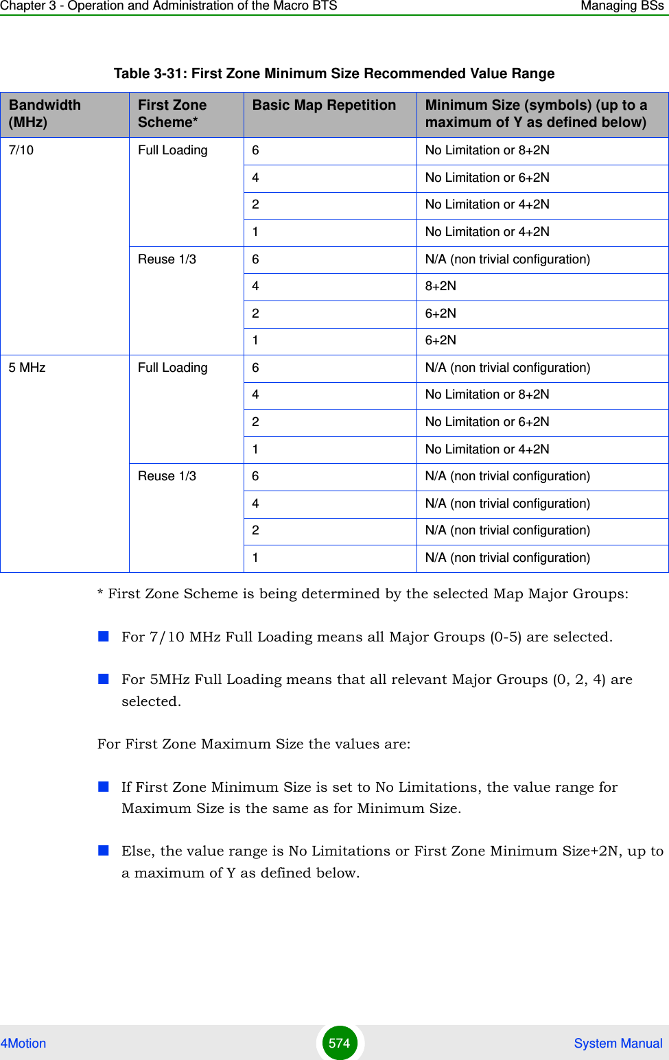
![Chapter 3 - Operation and Administration of the Macro BTS Managing BSs4Motion 575 System ManualThe value of Y that sets the upper limit for the Minimum and Maximum Size parameters depends on the Maximum Cell Radius and Total Uplink Duration parameters, using the following formula:Y=A-3*(Total Uplink Duration)-(Extra TTG), where A=46 for BW of 5 or 10 MHz, and 32 for BW of 7 MHz.3.9.12.3 Restoring Default Values for Airframe Configuration ParametersAfter enabling the Airframe configuration mode you can restore the default values for non-mandatory parameters in the following parameters tables:General (refer to Section 3.9.12.3.1)Map Zone (refer to Section 3.9.12.3.2)Downlink Diversity (refer to Section 3.9.12.3.3)Mimo (refer to Section 3.9.12.3.4)3.9.12.3.1 Restoring the Default Values of Airframe General ParametersTo restore one the Airframe non-mandatory General parameter to the default value, run the following command:npu(config-bs-66053-airframe)# no general [preamble-grp] [frame-offset ] [nbr-beam-forming ]Table 3-32: Calculating the Upper Limit Value (Y) for Minimum and Maximum SizeBandwidth (MHz) Maximum Cell Radius Total Uplink Duration (slots) Extra TTG (symbols)5/10 1, 2, 4, 8 4, 6 01, 2, 4, 8, 15, 23 5, 7 115, 23, 30 4, 6 230 5, 7 37 1, 2, 4, 8, 15, 23 4 01, 2, 4, 8, 15, 23, 30 3, 5 130 4 2](https://usermanual.wiki/Alvarion-Technologies/MICRO-25.Manual-p5/User-Guide-1329246-Page-28.png)
![Chapter 3 - Operation and Administration of the Macro BTS Managing BSs4Motion 576 System Manual3.9.12.3.2 Restoring the Default Values of Airframe Map Zone ParametersTo restore one or all of the Airframe Map Zone non-mandatory parameters to their default values, run the following command:npu(config-bs-66053-airframe)# no mapzone [size] [repetition] [RCID-Usage ]You can restore only one parameter to the default value by specifying only that parameter. For example, to restore only the size parameter to the default value, run the following command:npu(config-bs-66053-airframe)# no mapzone sizeThe parameter will be restored to its default value, while the other parameters will remain unchanged.To restore all non-mandatory parameters to their default value, run the following command:npu(config-bs-66053-airframe)# no mapzoneNOTERefer to Section 3.9.12.2.1 for a description and default values of the parameter.Command Syntaxnpu(config-bs-66053-airframe)# no general [preamble-grp ] [frame-offset ] [nbr-beam-forming ]Privilege Level10Command Modesbs airframe configuration modeNOTERefer to Section 3.9.12.2.2 for a description and default values of these parameters.Command Syntaxnpu(config-bs-66053-airframe)# no mapzone [size ] [repetition ] [RCID-Usage ]](https://usermanual.wiki/Alvarion-Technologies/MICRO-25.Manual-p5/User-Guide-1329246-Page-29.png)
![Chapter 3 - Operation and Administration of the Macro BTS Managing BSs4Motion 577 System Manual3.9.12.3.3 Restoring the Default Value of Airframe Downlink Diversity Mode ParameterTo restore the Airframe Downlink Diversity mode parameter to its default value, run the following command:npu(config-bs-66053-airframe)# no dldiversity modeSince the Downlink Diversity table contains a single parameter, it is sufficient to run the following command:npu(config-bs-66053-airframe)# no dldiversity3.9.12.3.4 Restoring the Default Values of Airframe MIMO ParametersTo restore one or all of the Airframe MIMO parameters to their default values, run the following command:npu(config-bs-66053-airframe)# no mimo [first-zone-min-size ] [first-zone-max-size ] [max-map-size ]To restore all MIMO parameters to their default values, run the following command:Privilege Level10Command Modesbs airframe configuration modeNOTERefer to Section 3.9.12.2.3 for a description and default values of these parameters.Command Syntaxnpu(config-bs-66053-airframe)# no dldiversity [mode ]Privilege Level10Command Modesbs airframe configuration mode](https://usermanual.wiki/Alvarion-Technologies/MICRO-25.Manual-p5/User-Guide-1329246-Page-30.png)
![Chapter 3 - Operation and Administration of the Macro BTS Managing BSs4Motion 578 System Manualnpu(config-bs-66053-airframe)# no mimo3.9.12.4 Terminating the Airframe Configuration ModeRun the following command to terminate the Airframe configuration mode:npu(config-bs-66053-airframe)# exit3.9.12.5 Displaying Configuration Information for Airframe ParametersYou can display the current configuration information for the following Airframe parameters tables:General (refer to Section 3.9.12.5.1)NOTERefer to Section 3.9.12.2.7 for a description and default values of these parameters.Command Syntaxnpu(config-bs-66053-airframe)# no mimo [first-zone-min-size ] [first-zone-max-size ] [max-map-size ]Privilege Level10Command Modesbs airframe configuration modeIMPORTANTDo not forget to execute the apply command before terminating the Airframe configuration mode: npu(config-bs-66053-airframe)# applyCommand Syntaxnpu(config-bs-66053-airframe)# exitPrivilege Level10Command Modesbs airframe configuration mode](https://usermanual.wiki/Alvarion-Technologies/MICRO-25.Manual-p5/User-Guide-1329246-Page-31.png)
![Chapter 3 - Operation and Administration of the Macro BTS Managing BSs4Motion 579 System ManualMap Zone (refer to Section 3.9.12.5.2)Downlink Diversity (refer to Section 3.9.12.5.3)Uplink Feedback Zone (refer to Section 3.9.12.5.4)Downlink Data Zone (refer to Section 3.9.12.5.5)Uplink Data Zone (refer to Section 3.9.12.5.6)Mimo (refer to Section 3.9.12.5.7)All (refer to Section 3.9.12.5.8)3.9.12.5.1 Displaying Configuration Information for Airframe General ParametersTo display configuration for the Airframe General parameters, run the following command:npu# show airframe-general bs [<(1 to 16777215 StepSize 1)>]Specify the BS ID if you want to display configuration for a particular BS. For example, to display the Airframe General parameters of BS 66503, run the following command:npu# show airframe-general bs 66053 Do not specify the BS ID if you want to view configuration information for all existing BSs. To display information for all BSs, run the following command:npu# show airframe-general bsCommand Syntaxnpu# show airframe-general bs [<(1 to 16777215 StepSize 1)> ]Privilege Level1](https://usermanual.wiki/Alvarion-Technologies/MICRO-25.Manual-p5/User-Guide-1329246-Page-32.png)
![Chapter 3 - Operation and Administration of the Macro BTS Managing BSs4Motion 580 System Manual3.9.12.5.2 Displaying Configuration Information for Airframe Map Zone ParametersTo display configuration for the Airframe Map Zone parameters, run the following command:npu# show airframe-mapzone bs [<(1 to 16777215 StepSize 1)>]Specify the BS ID if you want to display configuration for a particular BS. For example, to display the Airframe Map Zone parameters of BS 66503, run the following command:npu# show airframe-mapzone bs 66053 Do not specify the BS ID if you want to view configuration information for all existing BSs. To display information for all BSs, run the following command:Syntax Description Parameter Description Presence Default ValuePossible Values<(1 to 16777215 StepSize 1)>The BS ID Specify a value for this parameter if you want to display the Airframe General parameters of a specific BS. Do not specify a value for this parameter if you want to display the Airframe General parameters of all BSs.Optional N/A 1-16777215Display Format(for each existing Neighbor BS in each of the existing BSs if requested for all)BSIDLSB :<value>CellID :<value>PreambleGroup :<value>SegmentNumber :<value>FrameNumberOffset :<value>TotalUplinkDuration(slots) :<value>NeighbourBeamForming :<yes/no>Command ModesGlobal command mode](https://usermanual.wiki/Alvarion-Technologies/MICRO-25.Manual-p5/User-Guide-1329246-Page-33.png)
![Chapter 3 - Operation and Administration of the Macro BTS Managing BSs4Motion 581 System Manualnpu# show airframe-mapzone bs3.9.12.5.3 Displaying Configuration Information for Airframe Downlink Diversity ParametersTo display configuration for the Airframe Downlink Diversity parameters, run the following command:npu# show airframe-dldiversity bs [<(1 to 16777215 StepSize 1)>]Command Syntaxnpu# show airframe-mapzone bs [<(1 to 16777215 StepSize 1)> ]Privilege Level1Syntax Description Parameter Description Presence Default ValuePossible Values<(1 to 16777215 StepSize 1)>The BS ID Specify a value for this parameter if you want to display the Airframe Map Zone parameters of a specific BS. Do not specify a value for this parameter if you want to display the Airframe Map Zone parameters of all BSs.Optional N/A 1-16777215Display Format(for each existing Neighbor BS in each of the existing BSs if requested for all)BSIDLSB :<value>MapZoneSize(symbols) :<value>MapMajorGroups :<value>BasicMapRepetitions :<value>RcidUsage :<enable/disable>Command ModesGlobal command mode](https://usermanual.wiki/Alvarion-Technologies/MICRO-25.Manual-p5/User-Guide-1329246-Page-34.png)
![Chapter 3 - Operation and Administration of the Macro BTS Managing BSs4Motion 582 System ManualSpecify the BS ID if you want to display configuration for a particular BS. For example, to display the Airframe Downlink Diversity parameters of BS 66503, run the following command:npu# show airframe-dldiversity bs 66053 Do not specify the BS ID if you want to view configuration information for all existing BSs. To display information for all BSs, run the following command:npu# show airframe-dldiversity bsCommand Syntaxnpu# show airframe-dldiversity bs [<(1 to 16777215 StepSize 1)> ]Privilege Level1Syntax Description Parameter Description Presence Default ValuePossible Values<(1 to 16777215 StepSize 1)>The BS ID Specify a value for this parameter if you want to display the Airframe Downlink Diversity parameters of a specific BS. Do not specify a value for this parameter if you want to display the Airframe Downlink Diversity parameters of all BSs.Optional N/A 1-16777215Display Format(for each existing Neighbor BS in each of the existing BSs if requested for all)BSIDLSB :<value>DownlinkDataDiversityMode :<value>](https://usermanual.wiki/Alvarion-Technologies/MICRO-25.Manual-p5/User-Guide-1329246-Page-35.png)
![Chapter 3 - Operation and Administration of the Macro BTS Managing BSs4Motion 583 System Manual3.9.12.5.4 Displaying Configuration Information for Airframe Uplink Feedback Zone ParametersTo display configuration for the Airframe Uplink Feedback Zone parameters, run the following command:npu# show airframe-ulfeedbackzone bs [<(1 to 16777215 StepSize 1)>]Specify the BS ID if you want to display configuration for a particular BS. For example, to display the Airframe Uplink Feedback Zone parameters of BS 66503, run the following command:npu# show airframe-ulfeedbackzone bs 66053 Do not specify the BS ID if you want to view configuration information for all existing BSs. To display information for all BSs, run the following command:npu# show airframe-ulfeedbackzone bsCommand ModesGlobal command modeCommand Syntaxnpu# show airframe-ulfeedbackzone bs [<(1 to 16777215 StepSize 1)> ]Privilege Level1Syntax Description Parameter Description Presence Default ValuePossible Values<(1 to 16777215 StepSize 1)>The BS ID Specify a value for this parameter if you want to display the Airframe Uplink Feedback Zone parameters of a specific BS. Do not specify a value for this parameter if you want to display the Airframe Uplink Feedback Zone parameters of all BSs.Optional N/A 1-16777215](https://usermanual.wiki/Alvarion-Technologies/MICRO-25.Manual-p5/User-Guide-1329246-Page-36.png)
![Chapter 3 - Operation and Administration of the Macro BTS Managing BSs4Motion 584 System Manual3.9.12.5.5 Displaying Configuration Information for Airframe Downlink Data Zone ParametersTo display configuration for the Airframe Downlink Data Zone parameters, run the following command:npu# show airframe-dldatazone bs [<(1 to 16777215 StepSize 1)>]Specify the BS ID if you want to display configuration for a particular BS. For example, to display the Airframe Downlink Data Zone parameters of BS 66503, run the following command:npu# show airframe-dldatazone bs 66053 Do not specify the BS ID if you want to view configuration information for all existing BSs. To display information for all BSs, run the following command:npu# show airframe-dldatazone bsDisplay Format(for each existing Neighbor BS in each of the existing BSs if requested for all)BSIDLSB :<value>ULFeedbackZonePermutationBase :<value>Command ModesGlobal command modeCommand Syntaxnpu# show airframe-dldatazone bs [<(1 to 16777215 StepSize 1)> ]Privilege Level1](https://usermanual.wiki/Alvarion-Technologies/MICRO-25.Manual-p5/User-Guide-1329246-Page-37.png)
![Chapter 3 - Operation and Administration of the Macro BTS Managing BSs4Motion 585 System Manual3.9.12.5.6 Displaying Configuration Information for Airframe Uplink Data Zone ParametersTo display configuration for the Airframe Uplink Data Zone parameters, run the following command:npu# show airframe-uldatazone bs [<(1 to 16777215 StepSize 1)>]Specify the BS ID if you want to display configuration for a particular BS. For example, to display the Airframe Uplink Data Zone parameters of BS 66503, run the following command:npu# show airframe-uldatazone bs 66053 Do not specify the BS ID if you want to view configuration information for all existing BSs. To display information for all BSs, run the following command:Syntax Description Parameter Description Presence Default ValuePossible Values<(1 to 16777215 StepSize 1)>The BS ID Specify a value for this parameter if you want to display the Airframe Downlink Data Zone parameters of a specific BS. Do not specify a value for this parameter if you want to display the Airframe Downlink Data Zone parameters of all BSs.Optional N/A 1-16777215Display Format(for each existing Neighbor BS in each of the existing BSs if requested for all)BSIDLSB :<value>DLDATAZonePermutationBase :<value>Command ModesGlobal command mode](https://usermanual.wiki/Alvarion-Technologies/MICRO-25.Manual-p5/User-Guide-1329246-Page-38.png)
![Chapter 3 - Operation and Administration of the Macro BTS Managing BSs4Motion 586 System Manualnpu# show airframe-uldatazone bs3.9.12.5.7 Displaying Configuration Information for Airframe MIMO ParametersTo display configuration for the Airframe MIMO parameters, run the following command:Command Syntaxnpu# show airframe-uldatazone bs [<(1 to 16777215 StepSize 1)> ]Privilege Level1Syntax Description Parameter Description Presence Default ValuePossible Values<(1 to 16777215 StepSize 1)>The BS ID Specify a value for this parameter if you want to display the Airframe Uplink Data Zone parameters of a specific BS. Do not specify a value for this parameter if you want to display the Airframe Uplink Data Zone parameters of all BSs.Optional N/A 1-16777215Display Format(for each existing Neighbor BS in each of the existing BSs if requested for all)BSIDLSB :<value>ULDATAPermutationBase :<value>Command ModesGlobal command mode](https://usermanual.wiki/Alvarion-Technologies/MICRO-25.Manual-p5/User-Guide-1329246-Page-39.png)
![Chapter 3 - Operation and Administration of the Macro BTS Managing BSs4Motion 587 System Manualnpu# show airframe-mimo bs [<(1 to 16777215 StepSize 1)>]Specify the BS ID if you want to display configuration for a particular BS. For example, to display the Airframe MIMO parameters of BS 66503, run the following command:npu# show airframe-mimo bs 66053 Do not specify the BS ID if you want to view configuration information for all existing BSs. To display information for all BSs, run the following command:npu# show airframe-mimo bsCommand Syntaxnpu# show airframe-mimo bs [<(1 to 16777215 StepSize 1)> ]Privilege Level1Syntax Description Parameter Description Presence Default ValuePossible Values<(1 to 16777215 StepSize 1)>The BS ID Specify a value for this parameter if you want to display the Airframe Dynamic Permutation parameters of a specific BS. Do not specify a value for this parameter if you want to display the Airframe Dynamic Permutation parameters of all BSs.Optional N/A 1-16777215Display Format(for each existing Neighbor BS in each of the existing BSs if requested for all)BSIDLSB :<value>firstzoneminsize :<value>firstzonemaxsize :<value>maxmapsize :<value>](https://usermanual.wiki/Alvarion-Technologies/MICRO-25.Manual-p5/User-Guide-1329246-Page-40.png)
![Chapter 3 - Operation and Administration of the Macro BTS Managing BSs4Motion 588 System Manual3.9.12.5.8 Displaying Configuration Information for All Airframe ParametersTo display configuration for all Airframe parameters, run the following command:npu# show airframe-all bs [<(1 to 16777215 StepSize 1)>]Specify the BS ID if you want to display configuration for a particular BS. For example, to display all Airframe parameters of BS 66503, run the following command:npu# show airframe-all bs 66053 Do not specify the BS ID if you want to view configuration information for all existing BSs. To display information for all BSs, run the following command:npu# show airframe-all bsCommand ModesGlobal command modeCommand Syntaxnpu# show airframe-all bs [<(1 to 16777215 StepSize 1)> ]Privilege Level10Syntax Description Parameter Description Presence Default ValuePossible Values<(1 to 16777215 StepSize 1)>The BS ID Specify a value for this parameter if you want to display all Airframe parameters of a specific BS. Do not specify a value for this parameter if you want to display all Airframe parameters of all BSs.Optional N/A 1-16777215Command ModesGlobal command mode](https://usermanual.wiki/Alvarion-Technologies/MICRO-25.Manual-p5/User-Guide-1329246-Page-41.png)
![Chapter 3 - Operation and Administration of the Macro BTS Managing BSs4Motion 589 System Manual3.9 .13 Managing BS Bearer Interface Pa ra m etersAfter enabling the BS configuration mode, you can execute the following tasks:Configure one or more of the Bearer Interface parameters (refer to Section 3.9.13.1).Restore the default values of some or all of the Bearer Interface parameters (refer to Section 3.9.13.2).You can display configuration information for the Bearer Interface parameters of a selected or all existing BSs (refer to Section 3.9.13.3).3.9.13.1 Configuring Bearer Interface ParametersFrom the BS configuration mode, run the following command:npu(config-bs-66053)# bearer [ip-address <ip address>] [ip-subnetmask <ip address>] [dflt-gw <ip address>] [bearer-vlan <(9 to 9 StepSize 1) | (11 to 100 StepSize 1) |(110 to 4094 StepSize 1)> ]To configure the Bearer Interface Parameters:Command Syntaxnpu(config-bs-66053)# bearer [ip-address <ip address> ] [ip-subnetmask <ip address> ] [dflt-gw <ip address> ] [bearer-vlan <(9 to 9 StepSize 1) | (11 to 100 StepSize 1) |(110 to 4094 StepSize 1)> ]Privilege Level10Syntax Description Parameter Description Presence Default ValuePossible Values](https://usermanual.wiki/Alvarion-Technologies/MICRO-25.Manual-p5/User-Guide-1329246-Page-42.png)
![Chapter 3 - Operation and Administration of the Macro BTS Managing BSs4Motion 590 System Manual3.9.13.2 Restoring the Default Values of Bearer Interface ParametesTo restore the default values of the Bearer Interface bearer-vlan parameter, run the following command:npu(config-bs-66053)# no bearer [bearer-vlan][ip-address <ip address> ]The IP address of the bearer interface of the BS. Must be unique in the network. All BS bearer interfaces of the unit should be in the same subnet, together with the NPU’s bearer interface (if applicable).Mandatory when creating a new BS.N/A IP address[ip-subnetmask <ip address> ]The IP subnet mask of the bearer interface of the BSMandatory when creating a new BS.N/A Subnet mask[dflt-gw <ip address> ] The IP address of the default gateway of the bearer interface of the BS. Must be in the same subnet with the BS bearer ip interface.Mandatory when creating a new BS.N/A IP address[bearer-vlan <(9 to 9 StepSize 1) | (11 to 100 StepSize 1) |(110 to 4094 StepSize 1)> ]The VLAN ID of the bearer interface of the BS.Must be equal to the VLAN ID of the Bearer interface (see Section 3.4.2.3.5)Optional 11 9, 11-100, 110-4094.Command Modesbs configuration modeIMPORTANTWhen creating a new BS, the Bearer Interface mandatory parameters must be configured.NOTERefer to Section 3.9.13.1 for a description and default value of this parameter.](https://usermanual.wiki/Alvarion-Technologies/MICRO-25.Manual-p5/User-Guide-1329246-Page-43.png)
![Chapter 3 - Operation and Administration of the Macro BTS Managing BSs4Motion 591 System Manual3.9.13.3 Displaying Configuration Information for Bearer Interface ParametersTo display configuration information of Bearer Interface parameters, run the following command:npu# show bearer bs [<(1 to 16777215 StepSize 1)Specify the BS ID if you want to display information for a particular BS. For example, to display the Bearer Interface parameters of BS 66053, run the following command:npu# show bearer bs 66053Do not specify this parameter if you want to view information for all existing BSs. To display information for all BSs, run the following command:npu# show bearer bsCommand Syntaxnpu(config-bs-66053)# no bearer [bearer-vlan ]Privilege Level10Command Modesbs configuration modeCommand Syntaxnpu# show bearer bs [<(1 to 16777215 StepSize 1)Privilege Level1](https://usermanual.wiki/Alvarion-Technologies/MICRO-25.Manual-p5/User-Guide-1329246-Page-44.png)
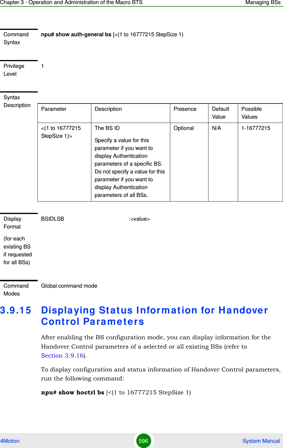
![Chapter 3 - Operation and Administration of the Macro BTS Managing BSs4Motion 593 System ManualYou can display configuration information for the Authentication parameters of a selected or all existing BSs (refer to Section 3.9.14.3).3.9.14.1 Configuring Authentication ParametersFrom the BS configuration mode, run the following command:npu(config-bs-66053)# auth-general [dflt-auth-ip-address <ip address>] [suspendedeapprocthrshld <(0 to 10000 StepSize 1)>] [activemsthrshld <(0 to 1024 StepSize 1)>] [maxeaproundsthrshld <(0 to 100 StepSize 1)>] To configure the Authentication parameters:Command Syntaxnpu(config-bs-66053)# auth-general [dflt-auth-ip-address <ip address> ] [suspendedeapprocthrshld <(0 to 10000 StepSize 1)> ] [activemsthrshld <(0 to 1024 StepSize 1)> ] [maxeaproundsthrshld <(0 to 100 StepSize 1)> ] ]Privilege Level10Syntax Description Parameter Description Presence Default ValuePossible Values[dflt-auth-ip-address <ip address> ]Identifier (IP address) of “default” authenticator ASN GW.Mandatory when creating a new BS.N/A IPv4 address[suspendedeapprocthrshld <(0 to 10000 StepSize 1)> ]Suspended EAP authentication process threshold. It is used to set an alarm.A value of 0 means that the alarm is disabled.In the current release the relevant alarm is not supported.Optional 10000 0 to 10000](https://usermanual.wiki/Alvarion-Technologies/MICRO-25.Manual-p5/User-Guide-1329246-Page-46.png)
![Chapter 3 - Operation and Administration of the Macro BTS Managing BSs4Motion 594 System Manual3.9.14.2 Restoring the Default Values of Authentication ParametesTo restore the default values of some or all of the Authentication parameters, run the following command:npu(config-bs-66053)# no auth-general [suspendedeapprocthrshld] [activemsthrshld] [maxeaproundsthrshld] You can restore only some parameters to their default values by specifying only those parameters. For example, to restore only the activemsthrshld and [activemsthrshld <(0 to 1024 StepSize 1)> ]Threshold for the number of MSs in active operation state (not Idle) served by the BS. Exceeding this threshold will set the alarm “Excessive MS number”.A value of 0 means that the alarm is disabled.Optional 1024 0 to 1024[maxeaproundsthrshld <(0 to 100 StepSize 1)> ]Threshold for the number of EAP rounds in one direction in the same EAP session. When exceeding this threshold; alarm is set. May be used to protect the system from hazard EAP sessions with extreme number of messaging round trips. A value of "0" means the alarm is disabled.A value of 0 means that the alarm is disabled.In the current release the relevant alarm is not supported.Optional 100 0 to 100Command Modesbs configuration modeIMPORTANTWhen creating a new BS, the Authentication dflt-auth-ip-address mandatory parameter must be configured.](https://usermanual.wiki/Alvarion-Technologies/MICRO-25.Manual-p5/User-Guide-1329246-Page-47.png)
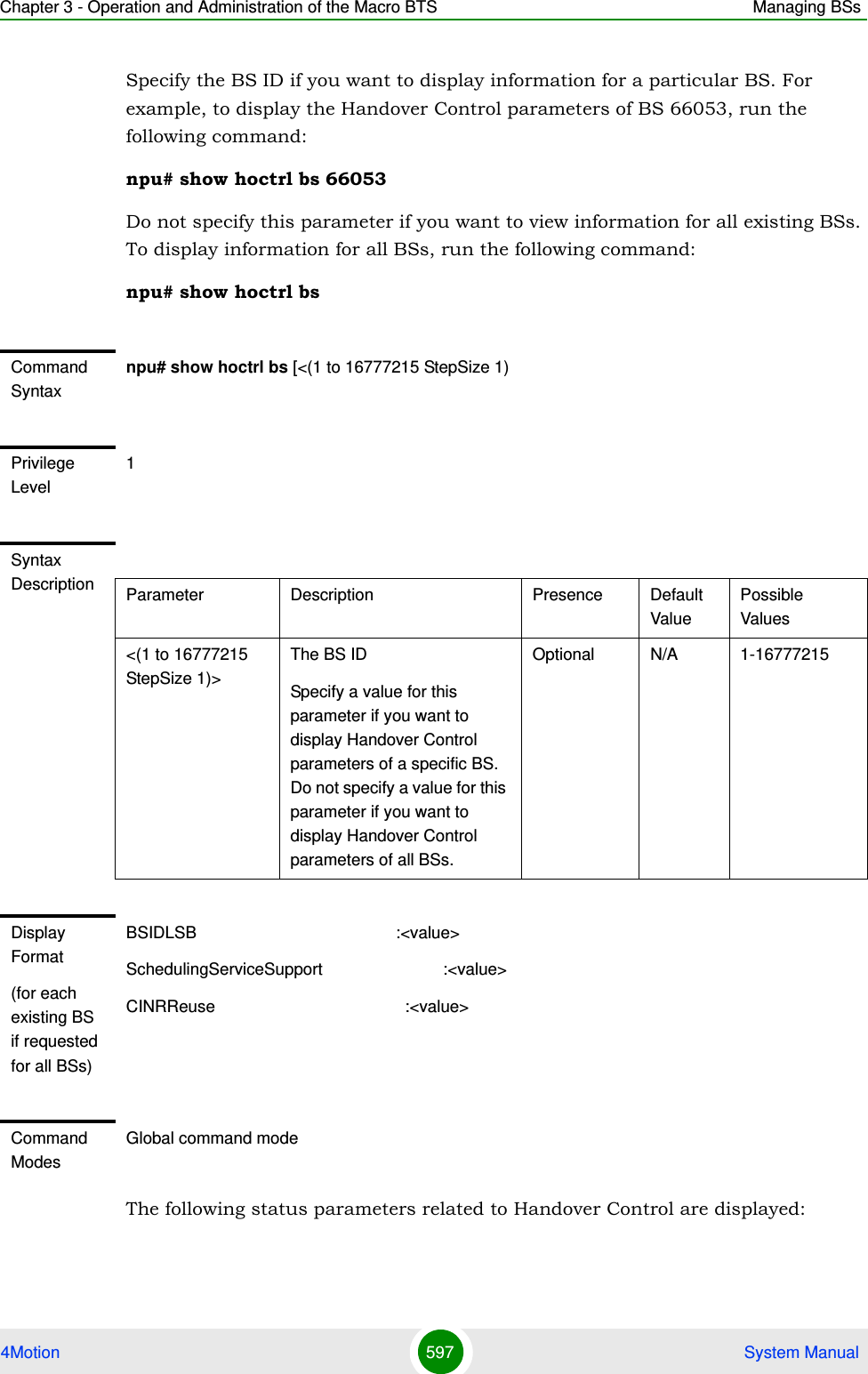
![Chapter 3 - Operation and Administration of the Macro BTS Managing BSs4Motion 595 System Manualmaxeaproundsthrshld parameters to the default values, run the following command:npu(config-bs-66053)# no auth-general activemsthrshld maxeaproundsthrshldThese parameters will be restored to their default values, while the other parameters will remain unchanged.To restore all Authentication parameters to their default value, run the following command:npu(config-bs-66053)# no auth-general3.9.14.3 Displaying Configuration Information for Authentication ParametersTo display configuration information of Authentication parameters, run the following command:npu# show auth-general bs [<(1 to 16777215 StepSize 1)Specify the BS ID if you want to display information for a particular BS. For example, to display the Authentication parameters of BS 66053, run the following command:npu# show auth-general bs 66053Do not specify this parameter if you want to view information for all existing BSs. To display information for all BSs, run the following command:npu# show auth-general bsNOTERefer to Section 3.9.14.1 for a description and default values of these parameters.Command Syntaxnpu(config-bs-66053)# no auth-general [suspendedeapprocthrshld ] [activemsthrshld ] [maxeaproundsthrshld ]Privilege Level10Command Modesbs configuration mode](https://usermanual.wiki/Alvarion-Technologies/MICRO-25.Manual-p5/User-Guide-1329246-Page-48.png)
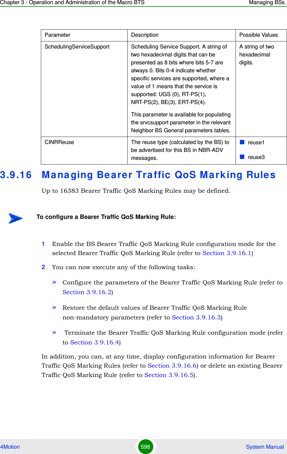
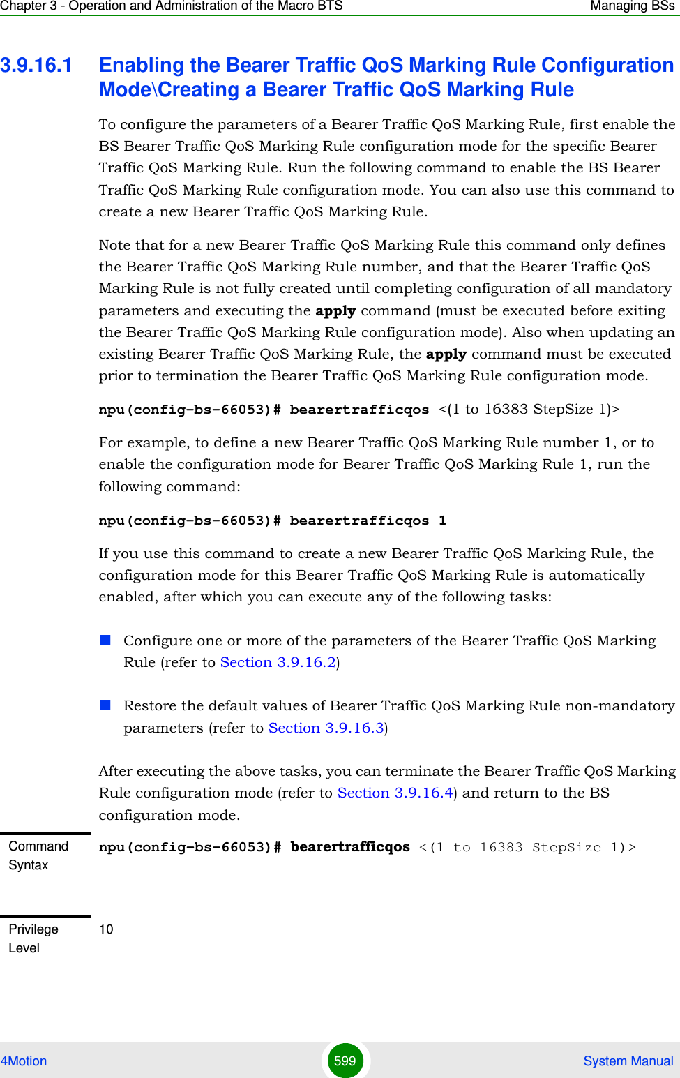
![Chapter 3 - Operation and Administration of the Macro BTS Managing BSs4Motion 600 System ManualFor example, to define Bearer Traffic QoS Marking Rule 1 for BS 66053, run the following command:npu(config-bs-66053)# bearertrafficqos 13.9.16.2 Configuring Bearer Traffic QoS Marking Rule ParametersTo configure the Bearer Traffic QoS Marking Rule parameters, run the following command:npu(config-bs-66053-bearertrafficqos-1)# mrkngrule [rule-status {Enable | Disable}] [rule-name <string (32)>] [srvcflow-datadeliverytype {uGS | rTVR | nRTVR | bE | eRTVR | any}] [srvcflow-trafficpriority <(0 to 7 StepSize 1) | (255 to 255 StepSize 1)>] [srvcflow-mediaflowtype <string (32)>] [enable-srvcflow-mediaflowtype {TRUE | FALSE}] [outerdscp <(0 to 63 StepSize 1)>] [bp8021p <(0 to 7 StepSize 1)>]Syntax Description Parameter Description Presence Default ValuePossible Valuesbearertrafficqos <(1 to 16383 StepSize 1)>The Bearer Traffic QoS Marking Rule numberMandatory 1 - 16383Command ModesBS configuration modeNOTEThe following examples are for BS Bearer Traffic QoS Marking Rule configuration mode for bs-66053, bearer traffic qos marking rule (bearertrafficqos)-1.IMPORTANTWhen creating a new Bearer Traffic QoS Marking Rule, the mandatory parameters must be configured.](https://usermanual.wiki/Alvarion-Technologies/MICRO-25.Manual-p5/User-Guide-1329246-Page-53.png)
![Chapter 3 - Operation and Administration of the Macro BTS Managing BSs4Motion 601 System ManualCommand Syntaxnpu(config-bs-66053-bearertrafficqos-1)# mrkngrule [rule-status {Enable | Disable} ] [rule-name <string (32)> ] [srvcflow-datadeliverytype {uGS | rTVR | nRTVR | bE | eRTVR | any} ] [srvcflow-trafficpriority <(0 to 7 StepSize 1) | (255 to 255 StepSize 1)> ] [srvcflow-mediaflowtype <string (32)> ] [enable-srvcflow-mediaflowtype {TRUE | FALSE} ] [outerdscp <(0 to 63 StepSize 1)> ] [bp8021p <(0 to 7 StepSize 1)> ]Privilege Level10Syntax Description Parameter Description Presence Default ValuePossible Valuesrule-status {Enable | Disable}The Bearer Traffic QoS Marking Rule statusOptional Enable EnableDisablerule-name <string (32)>The Bearer Traffic QoS Marking Rule name (descriptor).Optional null A string of up to 32 characterssrvcflow-datadeliverytype {uGS | rTVR | nRTVR | bE | eRTVR | any}Service Flow Type of data delivery services.Optional any uGSrTVRnRTVRbEeRTVRanysrvcflow-trafficpriority <(0 to 7 StepSize 1) | (255 to 255 StepSize 1)>Service Flow Traffic Priority. A value of 255 means "ANY"Optional 255 0-7 or 255](https://usermanual.wiki/Alvarion-Technologies/MICRO-25.Manual-p5/User-Guide-1329246-Page-54.png)
![Chapter 3 - Operation and Administration of the Macro BTS Managing BSs4Motion 602 System Manual3.9.16.3 Restoring Default Values for Bearer Traffic QoS Marking Rule Configuration ParametersAfter enabling the Bearer Traffic QoS Marking Rule configuration mode you can restore the default values for non-mandatory parameters. To restore some or all of the Bearer Traffic QoS Marking Rule non-mandatory parameters to their default values, run the following command:npu(config-bs-66053-bearertrafficqos-1)# no mrkngrule [rule-status] [rule-name] [srvcflow-datadeliverytype [srvcflow-trafficpriority] [outerdscp] [bp8021p]You can restore only one or several parameters to the default values by specifying only those parameters. For example, to restore only the outerdscp to the default value, run the following command:npu(config-bs-66053-bearertrafficqos-1)# no mrkngrule outerdscpThe parameter will be restored to its default value, while the other parameters will remain unchanged.srvcflow-mediaflowtype <string (32)>One of key entries into the traffic marking rules table. Media Flow Type should be defined in ASN-GW or AAA server.Only relevant if enable-srvcflow-mediaflowtype (see below) is TRUE.Mandatory when creating a new rule (if relevant)N/A A string of up to 32 charactersenable-srvcflow-mediaflowtype {TRUE | FALSE}If TRUE, the srvcflow-mediaflowtype (see above) will be considered. when looking for a match. If FALSE it will not be considered.Mandatory when creating a new ruleTRUEFALSEouterdscp <(0 to 63 StepSize 1)>DSCP value to be used for marking of outer IP header (IP/GRE).Optional 0 0 - 63bp8021p <(0 to 7 StepSize 1)>802.1p priority to be used for marking of trafficOptional 0 0 - 7Command Modesbs bearer traffic qos marking rule configuration mode](https://usermanual.wiki/Alvarion-Technologies/MICRO-25.Manual-p5/User-Guide-1329246-Page-55.png)
![Chapter 3 - Operation and Administration of the Macro BTS Managing BSs4Motion 603 System ManualTo restore all Bearer Traffic QoS Marking Rule non-mandatory parameters to their default value, run the following command:npu(config-bs-66053-bearertrafficqos-1)# no mrkngrule3.9.16.4 Terminating the Bearer Traffic QoS Marking Rule Configuration ModeRun the following command to terminate the Bearer Traffic QoS Marking Rule configuration mode:npu(config-bs-66053-bearertrafficqos-1)# exit3.9.16.5 Deleting a Bearer Traffic QoS Marking RuleRun the following command from the BS configuration mode to delete a Bearer Traffic QoS Marking Rule:npu(config-bs 66053)# no bearertrafficqos <(1 to 16383 StepSize 1)> NOTERefer to Section 3.9.16.2 for a description and default values of these parameters.Command Syntaxnpu(config-bs-66053-bearertrafficqos-1)# no mrkngrule [rule-status ] [rule-name ] [srvcflow-datadeliverytype [srvcflow-trafficpriority ] [outerdscp ] [bp8021p ]Privilege Level10Command Modesbs bearer traffic qos marking rule configuration modeCommand Syntaxnpu(config-bs-66053-bearertrafficqos-1)# exitPrivilege Level10Command Modesbs bearer traffic qos marking rule configuration mode](https://usermanual.wiki/Alvarion-Technologies/MICRO-25.Manual-p5/User-Guide-1329246-Page-56.png)
![Chapter 3 - Operation and Administration of the Macro BTS Managing BSs4Motion 604 System Manual3.9.16.6 Displaying Configuration Information for Bearer Traffic QoS Marking RulesTo display configuration for the parameters of a specific or all Bearer Traffic QoS Marking Rules, run the following command:npu# show bearertrafficqos bs [<(1 to 16777215 StepSize 1)> number <(1 to 16383 StepSize 1)>]Specify the BS ID and Bearer Traffic QoS Marking Rule number if you want to display configuration for a particular Bearer Traffic QoS Marking Rule. For example, to display the parameters of Bearer Traffic QoS Marking Rule 1 in BS 66053, run the following command:npu# show bearertrafficqos bs 66053 number 1Do not specify these parameters if you want to view configuration information for all existing Bearer Traffic QoS Marking Rules. To display information for all Bearer Traffic QoS Marking Rules, run the following command:npu# show bearertrafficqos bsCommand Syntaxnpu(config-bs 66053)# no bearertrafficqos <(1 to 16383 StepSize 1)> Privilege Level10Syntax Description Parameter Description Presence Default ValuePossible Values<(1 to 16383 StepSize 1)>The Bearer Traffic QoS Marking Rule number Mandatory N/A 1-16383Command Modesbs configuration modeCommand Syntaxnpu# show bearertrafficqos bs [<(1 to 16777215 StepSize 1)> number <(1 to 16383 StepSize 1)> ]](https://usermanual.wiki/Alvarion-Technologies/MICRO-25.Manual-p5/User-Guide-1329246-Page-57.png)
![Chapter 3 - Operation and Administration of the Macro BTS Managing BSs4Motion 605 System ManualPrivilege Level1Syntax Description Parameter Description Presence Default ValuePossible Values<(1 to 16777215 StepSize 1)>The BS ID Specify a value for this parameter if you want to display the parameters of a specific Bearer Traffic QoS Marking Rule. Do not specify a value for this parameter if you want to display the parameters of all Bearer Traffic QoS Marking Rules.Optional N/A 1-16777215number <(1 to 16383 StepSize 1)> ]The Bearer Traffic QoS Marking Rule number. To be used only if you want to display the parameters of a specific Bearer Traffic QoS Marking Rule.Optional N/A 1-16383Display Format(for each existing Service Mapping Rule if requested for all Service Mapping Rules)BSIDLSB :<value>RuleNumber :<value>RuleStatus :<value>RuleName :<value>ServiceFlowMediaFlowType :<value>ServiceFlowTrafficPriority(255meansany) :<value>ServiceFlowMediaFlowType :<value>EnableServiceFlowMediaFlowType :<value>OuterDSCP :<value>802.1pPriority :<value>Command ModesGlobal command mode](https://usermanual.wiki/Alvarion-Technologies/MICRO-25.Manual-p5/User-Guide-1329246-Page-58.png)
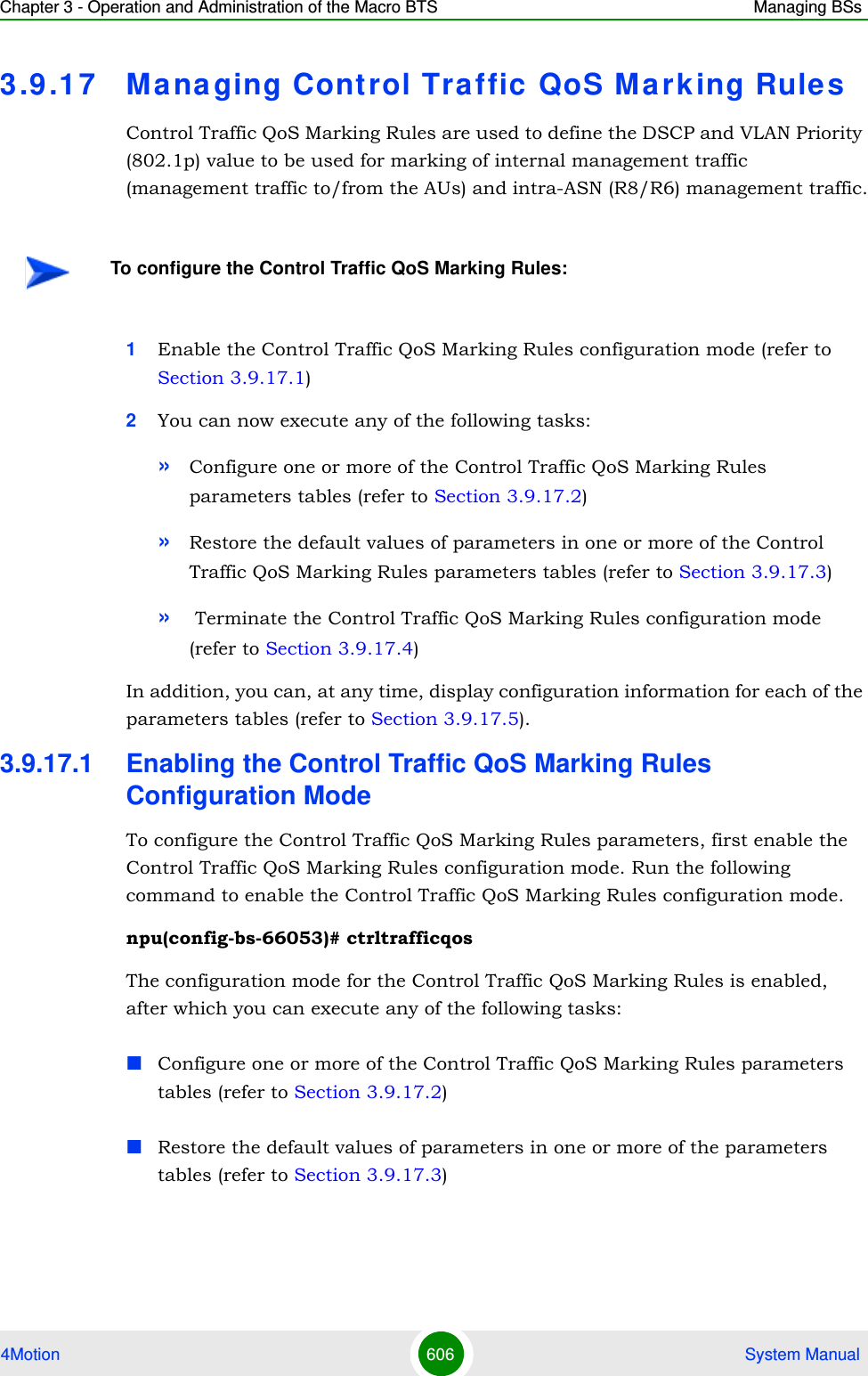
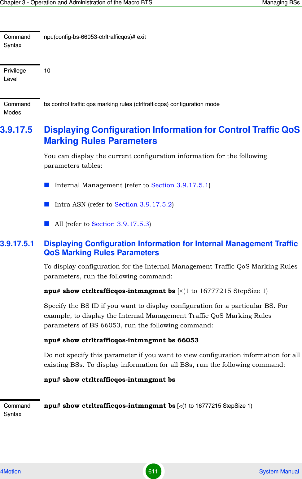
![Chapter 3 - Operation and Administration of the Macro BTS Managing BSs4Motion 607 System ManualAfter executing the above tasks, you can terminate the Control Traffic QoS Marking Rules configuration mode (refer to Section 3.9.17.4) and return to the BS configuration mode.3.9.17.2 Configuring Control Traffic QoS Marking Rules ParametersAfter enabling the Control Traffic QoS Marking Rules configuration mode you can configure the following parameters tables:Internal Management (refer to Section 3.9.17.2.1)Intra ASN (refer to Section 3.9.17.2.2)3.9.17.2.1 Configuring Internal Management Traffic QoS Marking Rules ParametersTo configure the Internal Management Traffic QoS Marking Rules, run the following command:npu(config-bs-66053-ctrltrafficqos)# intmngmnt [dscp <(0 to 63 StepSize 1)>] [inter8021p <(0 to 7 StepSize 1)>]Command Syntaxnpu(config-bs-66053)# ctrltrafficqosPrivilege Level10Command Modesbs configuration modeCommand Syntaxnpu(config-bs-66053-ctrltrafficqos)# intmngmnt [dscp <(0 to 63 StepSize 1)> ] [inter8021p <(0 to 7 StepSize 1)> ]Privilege Level10](https://usermanual.wiki/Alvarion-Technologies/MICRO-25.Manual-p5/User-Guide-1329246-Page-60.png)
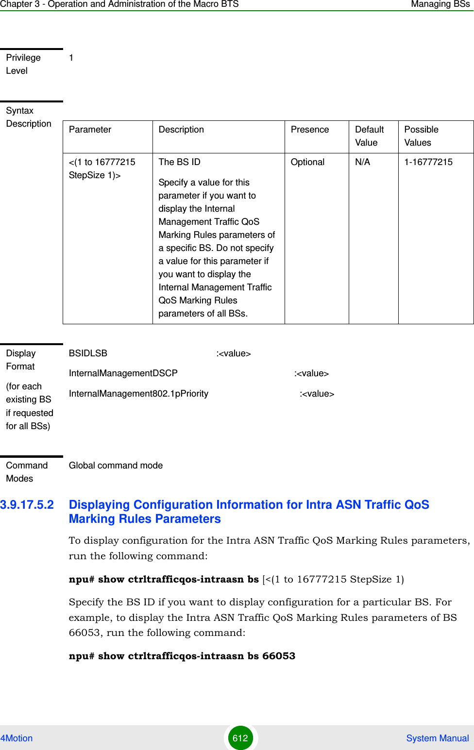
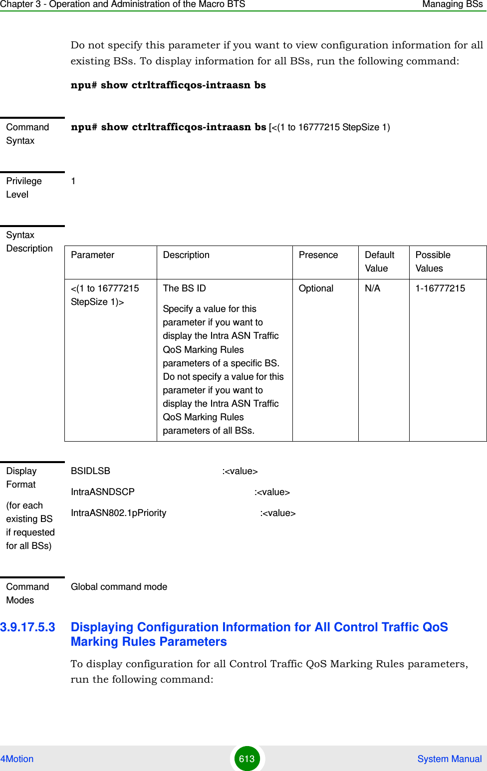
![Chapter 3 - Operation and Administration of the Macro BTS Managing BSs4Motion 608 System Manual3.9.17.2.2 Configuring the Intra ASN Traffic QoS Marking RulesTo configure the Intra ASN Traffic QoS Marking Rules parameters, run the following command:npu(config-bs-66053-ctrltrafficqos)# intraasn [dscp <(0 to 63 StepSize 1)>] [intra8021p <(0 to 7 StepSize 1)>]Syntax Description Parameter Description Presence Default ValuePossible Valuesdscp <(0 to 63 StepSize 1)>DSCP priority value to be used for marking of internal management trafficOptional 0 0 - 63inter8021p <(0 to 7 StepSize 1)>802.1p priority value to be used for marking of internal management trafficOptional 0 0 - 7Command Modesbs control traffic qos marking rules (ctrltrafficqos) configuration mode Command Syntaxnpu(config-bs-66053-ctrltrafficqos)# intraasn [dscp <(0 to 63 StepSize 1)> ] [intra8021p <(0 to 7 StepSize 1)> ]Privilege Level10Syntax Description Parameter Description Presence Default ValuePossible Valuesdscp <(0 to 63 StepSize 1)>DSCP priority value to be used for marking of intra-ASN (R8/R6) trafficOptional 0 0 - 63intra8021p <(0 to 7 StepSize 1)>802.1p priority value to be used for marking of intra-ASN (R8/R6) trafficOptional 0 0 - 7](https://usermanual.wiki/Alvarion-Technologies/MICRO-25.Manual-p5/User-Guide-1329246-Page-61.png)
![Chapter 3 - Operation and Administration of the Macro BTS Managing BSs4Motion 609 System Manual3.9.17.3 Restoring Default Values for Control Traffic QoS Marking Rules Configuration ParametersAfter enabling the Control Traffic QoS Marking Rules configuration mode you can restore the default values for parameters in the following parameters tables:Internal Management (refer to Section 3.9.17.3.1)Intra ASN (refer to Section 3.9.17.3.2)3.9.17.3.1 Restoring the Default Values of Internal Management Traffic QoS Marking Rules ParametersTo restore one or all of the Internal Management Traffic QoS Marking Rules parameters to their default values, run the following command:npu(config-bs-66053-ctrltrafficqos)# no intmngmnt [dscp] [inter8021p]You can restore only one parameter to its default values by specifying only that parameter. For example, to restore only dscp to the default value, run the following command:npu(config-bs-66053-ctrltrafficqos)# no intmngmnt dscpThe parameter will be restored to its default value, while the other parameter will remain unchanged.To restore all Internal Management Traffic QoS Marking Rules parameters to their default value, run the following command:npu(config-bs-66053-ctrltrafficqos)# no intmngmntCommand Modesbs control traffic qos marking rules (ctrltrafficqos) configuration mode NOTERefer to Section 3.9.17.2.1 for a description and default values of these parameters.Command Syntaxnpu(config-bs-66053-ctrltrafficqos)# no intmngmnt [dscp ] [inter8021p ]Privilege Level10](https://usermanual.wiki/Alvarion-Technologies/MICRO-25.Manual-p5/User-Guide-1329246-Page-62.png)
![Chapter 3 - Operation and Administration of the Macro BTS Managing BSs4Motion 610 System Manual3.9.17.3.2 Restoring the Default Values of Intra ASN Traffic QoS Marking Rules ParametersTo restore one or all of the Intra ASN Traffic QoS Marking Rules parameters to their default values, run the following command:npu(config-bs-66053-ctrltrafficqos)# no intraasn [dscp] [intra8021p]You can restore only one parameter to its default values by specifying only that parameter. For example, to restore only dscp to the default value, run the following command:npu(config-bs-66053-ctrltrafficqos)# no intraasn dscpThe parameter will be restored to its default value, while the other parameter will remain unchanged.To restore all Intra ASN Traffic QoS Marking Rules parameters to their default value, run the following command:npu(config-bs-66053-ctrltrafficqos)# no intraasn3.9.17.4 Terminating the Control Traffic QoS Marking Rules Configuration ModeRun the following command to terminate the Control Traffic QoS Marking Rules configuration mode:npu(config-bs-66053-ctrltrafficqos)# exitCommand Modesbs control traffic qos marking rules (ctrltrafficqos) configuration mode NOTERefer to Section 3.9.17.2.2 for a description and default values of these parameters.Command Syntaxnpu(config-bs-66053-ctrltrafficqos)# no intraasn [dscp ] [intra8021p ]Privilege Level10Command Modesbs control traffic qos marking rules (ctrltrafficqos) configuration mode](https://usermanual.wiki/Alvarion-Technologies/MICRO-25.Manual-p5/User-Guide-1329246-Page-63.png)
![Chapter 3 - Operation and Administration of the Macro BTS Managing BSs4Motion 615 System Manual3.9 .18 Managing ID-IP Mapping Pa ra m e t e rsAfter enabling the BS configuration mode, you can execute the following tasks:Configure one or more ID-IP Mapping entry (refer to Section 3.9.18.1).Delete one or more ID-IP Mapping entries (refer to Section 3.9.18.2).You can display configuration information for the ID-IP Mapping of a selected or all existing BSs (refer to Section 3.9.18.3).3.9.18.1 Configuring ID-IP Mapping EntriesFrom the BS configuration mode, run the following command:npu(config-bs-66053)# idip <(1 to 16777215 StepSize 1)> [nw-node-ip <ip address>]Command ModesGlobal command modeTo configure ID-IP Mapping entries:Command Syntaxnpu(config-bs-66053)# idip <(1 to 16777215 StepSize 1)> [nw-node-ip <ip address> ]Privilege Level10Syntax Description Parameter Description Presence Default ValuePossible Values<(1 to 16777215 StepSize 1)>The Next Hop (Network Node) BS IDMandatory N/A 1 - 16777215nw-node-ip <ip address> The Next Hop (Network Node) BS IP AddressMandatory N/A IP address](https://usermanual.wiki/Alvarion-Technologies/MICRO-25.Manual-p5/User-Guide-1329246-Page-68.png)
![Chapter 3 - Operation and Administration of the Macro BTS Managing BSs4Motion 616 System Manual3.9.18.2 Deleting an ID-IP Mapping EntryRun the following command from the BS configuration mode to delete an ID-IP Mapping entry:npu(config-bs 66053)# no idip <(1 to 16777215 StepSize 1)> 3.9.18.3 Displaying Configuration Information for ID-IP Mapping EntriesTo display configuration information of ID-IP Mapping entries, run the following command:npu# show idip bs [<(1 to 16777215 StepSize 1)> nw-node-id <(1 to 16777215 StepSize 1)>]Specify the BS ID and Next Hop (Network Node) BS ID (nw-node-id) if you want to display information for a particular ID-IP Mapping entry. For example, to display the ID-IP Mapping of BS 66053 and Network Node 66055, run the following command:Command Modesbs configuration modeIMPORTANTWhen creating a new BS, at least one ID-IP Mapping entry must be configured.Command Syntaxnpu(config-bs 66053)# no idip <(1 to 16777215 StepSize 1)> Privilege Level10Syntax Description Parameter Description Presence Default ValuePossible Values<(1 to 16777215 StepSize 1)>The Next Hop (Network Node) BS IDMandatory N/A 1 - 16777215Command Modesbs configuration mode](https://usermanual.wiki/Alvarion-Technologies/MICRO-25.Manual-p5/User-Guide-1329246-Page-69.png)
![Chapter 3 - Operation and Administration of the Macro BTS Managing BSs4Motion 617 System Manualnpu# show idip bs 66053 nw-node-id 66055Do not specify these parameters if you want to view information of ID-IP Mapping entries in all existing BSs. To display information for all BSs, run the following command:npu# show idip bsCommand Syntaxnpu# show idip bs [<(1 to 16777215 StepSize 1)> nw-node-id <(1 to 16777215 StepSize 1)> ]Privilege Level1Syntax Description Parameter Description Presence Default ValuePossible Values<(1 to 16777215 StepSize 1)>The BS ID Specify a value for this parameter if you want to display specific ID-IP Mapping entry in a specific BS. Do not specify a value for this parameter if you want to display all ID-IP Mapping entries of all BSs.Optional N/A 1-16777215nw-node-id <(1 to 16777215 StepSize 1)>The Next Hop (Network Node) BS ID.Specify a value for this parameter if you want to display a specific ID-IP Mapping entry in a specific BS. Do not specify a value for this parameter if you want to display all ID-IP Mapping entries of all BSs.Optional N/A 1-16777215](https://usermanual.wiki/Alvarion-Technologies/MICRO-25.Manual-p5/User-Guide-1329246-Page-70.png)
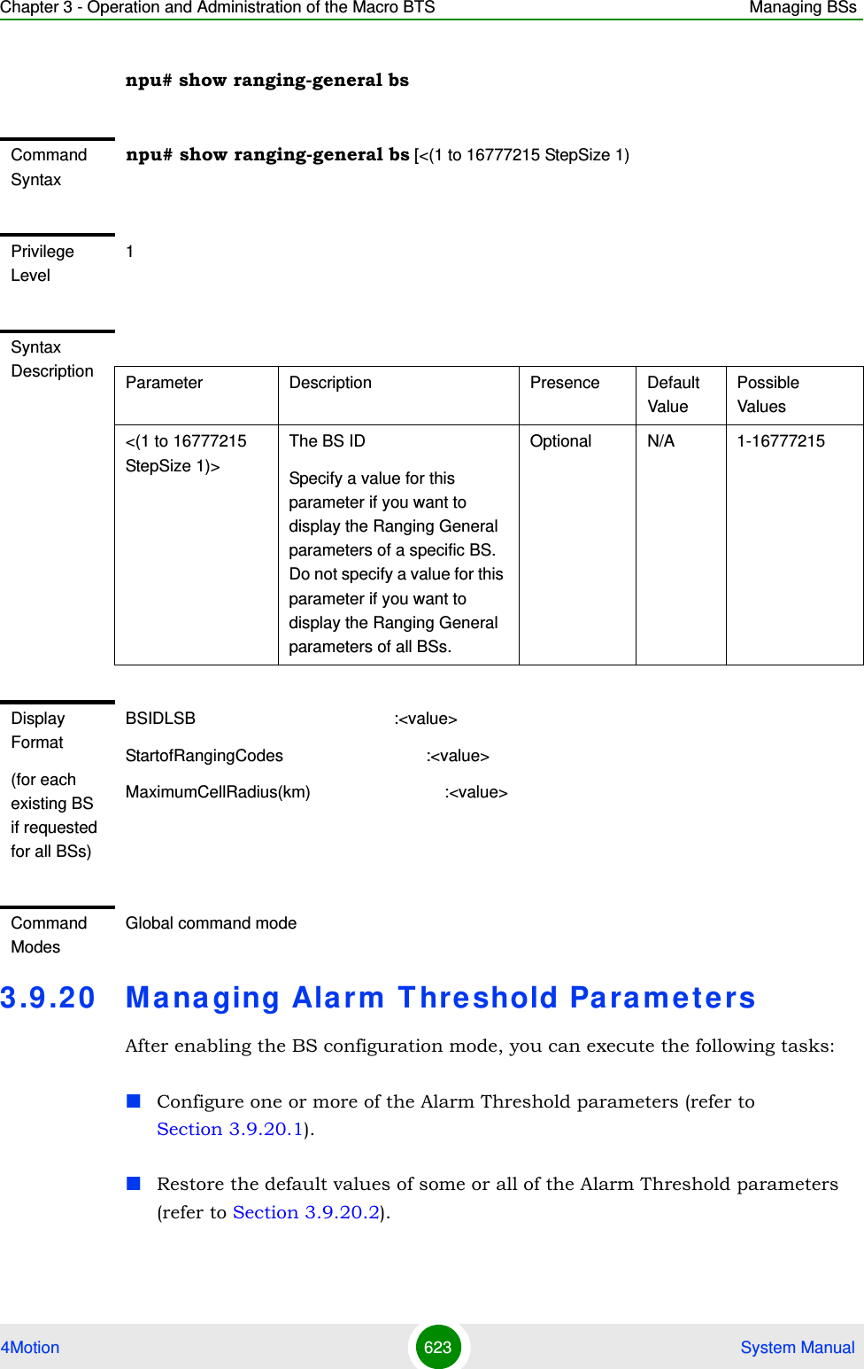
![Chapter 3 - Operation and Administration of the Macro BTS Managing BSs4Motion 620 System Manual3.9.19.2 Configuring Ranging ParametersTo configure the Ranging General parameters, run the following command:npu(config-bs-66053-ranging)# general [start-of-rng-codes <(0 to 255 StepSize 1)>] [max-cellradius {one | two | four | eight | fifteen | twentyThree | thirty}]Command Modesbs configuration modeCommand Syntaxnpu(config-bs-66053-ranging)# general [start-of-rng-codes <(0 to 255 StepSize 1)> ] [max-cellradius {one | two | four | eight | fifteen | twentyThree | thirty} ]Privilege Level10Syntax Description Parameter Description Presence Default ValuePossible Valuesstart-of-rng-codes <(0 to 255 StepSize 1)>Start of Ranging Codes: The starting number S of the group of codes used for this uplink.Actual valid values are 0, 64, 128, 192. If a different value is configured-the highest valid value that is lower than the configured value will be set (for example, for a configured value of 140 the actual value will be 128).Optional 0 0 - 255](https://usermanual.wiki/Alvarion-Technologies/MICRO-25.Manual-p5/User-Guide-1329246-Page-73.png)
![Chapter 3 - Operation and Administration of the Macro BTS Managing BSs4Motion 621 System Manual3.9.19.3 Restoring Default Values for Ranging Configuration ParametersTo restore one or all of the Ranging General parameters to their default values, run the following command:npu(config-bs-66053-ranging)# no general [start-of-rng-codes] [max-cellradius]You can restore only one parameter to its default values by specifying only this parameter. For example, to restore only max-cellradius to the default value, run the following command:npu(config-bs-66053-ranging)# no general max-cellradiusThe parameter will be restored to its default value, while the other parameter will remain unchanged.To restore all Ranging General parameters to their default value, run the following command:npu(config-bs-66053-ranging)# no generalmax-cellradius {one | two | four | eight | fifteen | twentyThree | thirty}The Maximum Cell Radius (in km)Optional two onetwofoureightfifteentwentyThreethirtyCommand Modesbs ranging configuration mode NOTERefer to Section 3.9.19.2 for a description and default values of these parameters.Command Syntaxnpu(config-bs-66053-ranging)# no general [start-of-rng-codes ] [max-cellradius ]](https://usermanual.wiki/Alvarion-Technologies/MICRO-25.Manual-p5/User-Guide-1329246-Page-74.png)
![Chapter 3 - Operation and Administration of the Macro BTS Managing BSs4Motion 624 System ManualYou can display configuration and status information for the Alarm Threshold parameters of a selected or all existing BSs (refer to Section 3.9.20.3).3.9.20.1 Configuring Alarm Threshold ParametersFrom the BS configuration mode, run the following command:npu(config-bs-66053)# alrm-thrshld [ul-mednoise <(-135 to -100 StepSize 1)>] [ul-99prcntnoise <(-135 to -100 StepSize 1)>] [Be-exc-dl-drop-thr <(1 to 1000 StepSize 1)> ] [rt-exc-dl-drop-thr <(1 to 1000 StepSize 1)> ] [nrt-exc-dl-drop-thr <(1 to 1000 StepSize 1)> ] [ugs-exc-dl-drop-thr <(1 to 1000 StepSize 1)> ] [ert-exc-dl-drop-thr <(1 to 1000 StepSize 1)> ]To configure the Alarm Threshold parameters:Command Syntaxnpu(config-bs-66053)# alrm-thrshld [ul-mednoise <(-135 to -100 StepSize 1)> ] [ul-99prcntnoise <(-135 to -100 StepSize 1)> ] [Be-exc-dl-drop-thr <(1 to 1000 StepSize 1)> ] [rt-exc-dl-drop-thr <(1 to 1000 StepSize 1)> ] [nrt-exc-dl-drop-thr <(1 to 1000 StepSize 1)> ] [ugs-exc-dl-drop-thr <(1 to 1000 StepSize 1)> ] [ert-exc-dl-drop-thr <(1 to 1000 StepSize 1)> ]Privilege Level10Syntax Description Parameter Description Presence Default ValuePossible Values](https://usermanual.wiki/Alvarion-Technologies/MICRO-25.Manual-p5/User-Guide-1329246-Page-77.png)
![Chapter 3 - Operation and Administration of the Macro BTS Managing BSs4Motion 625 System Manualul-mednoise <(-135 to -100 StepSize 1)>The uplink median noise level represents the median value of the noise floor histogram. If the uplink median noise level exceeds this value, an excessive uplink median noise alarm will be generated.The value is in dBm/tone.The default value is set to 3 dB above the default value of the target noise and interference level for the PUSC zone (target-ni parameter, see Section 3.9.4.2.1) Optional -124 -135 to -100ul-99prcntnoise <(-135 to -100 StepSize 1)>The uplink 99% noise level represents the 99% value of the noise floor histogram. If the uplink 99% noise level exceeds this value, an excessive uplink 99% percentile noise alarm will be generated.Optional -100 -135 to -100[Be-exc-dl-drop-thr <(1 to 1000 StepSize 1)> ]Threshold for Excessive DL Dropped Packets Ratio for Best Effort (in promils)Optional 1000 1 - 1000[rt-exc-dl-drop-thr <(1 to 1000 StepSize 1)> ]Threshold for Excessive DL Dropped Packets Ratio for Real Time (in promils)Optional 1000 1 - 1000[nrt-exc-dl-drop-thr <(1 to 1000 StepSize 1)> ]Threshold for Excessive DL Dropped Packets Ratio for Non Real Time (in promils)Optional 1000 1 - 1000[ugs-exc-dl-drop-thr <(1 to 1000 StepSize 1)> ]Threshold for Excessive DL Dropped Packets Ratio for UGS (in promils)Optional 1000 1 - 1000](https://usermanual.wiki/Alvarion-Technologies/MICRO-25.Manual-p5/User-Guide-1329246-Page-78.png)
![Chapter 3 - Operation and Administration of the Macro BTS Managing BSs4Motion 626 System Manual3.9.20.2 Restoring the Default Values of Alarm Threshold ParametesTo restore the default values of some or all of the Alarm Threshold parameters, run the following command:npu(config-bs-66053)# no alrm-thrshld [ul-mednoise] [ul-99prcntnoise] [Be-exc-dl-drop-thr ] [rt-exc-dl-drop-thr ] [nrt-exc-dl-drop-thr ] [ugs-exc-dl-drop-thr ] [ert-exc-dl-drop-thr ]You can restore only some parameters to the default values by specifying only those parameter. For example, to restore only the ul-mednoise parameter to the default value, run the following command:npu(config-bs-66053)# no alrm-thrshld ul-mednoiseThis parameter will be restored to its default value, while the other parameters will remain unchanged.To restore all Alarm Threshold parameters to their default value, run the following command:npu(config-bs-66053)# no alrm-thrshld[ert-exc-dl-drop-thr <(1 to 1000 StepSize 1)> ]Threshold for Excessive DL Dropped Packets Ratio for ERT (in promils)Optional 1000 1 - 1000Command Modesbs configuration modeNOTERefer to Section 3.9.20.1 for a description and default values of these parameters.Command Syntaxnpu(config-bs-66053)# no alrm-thrshld [ul-mednoise ] [ul-99prcntnoise ] [Be-exc-dl-drop-thr ] [rt-exc-dl-drop-thr ] [nrt-exc-dl-drop-thr ] [ugs-exc-dl-drop-thr ] [ert-exc-dl-drop-thr ]Privilege Level10Command Modesbs configuration mode](https://usermanual.wiki/Alvarion-Technologies/MICRO-25.Manual-p5/User-Guide-1329246-Page-79.png)
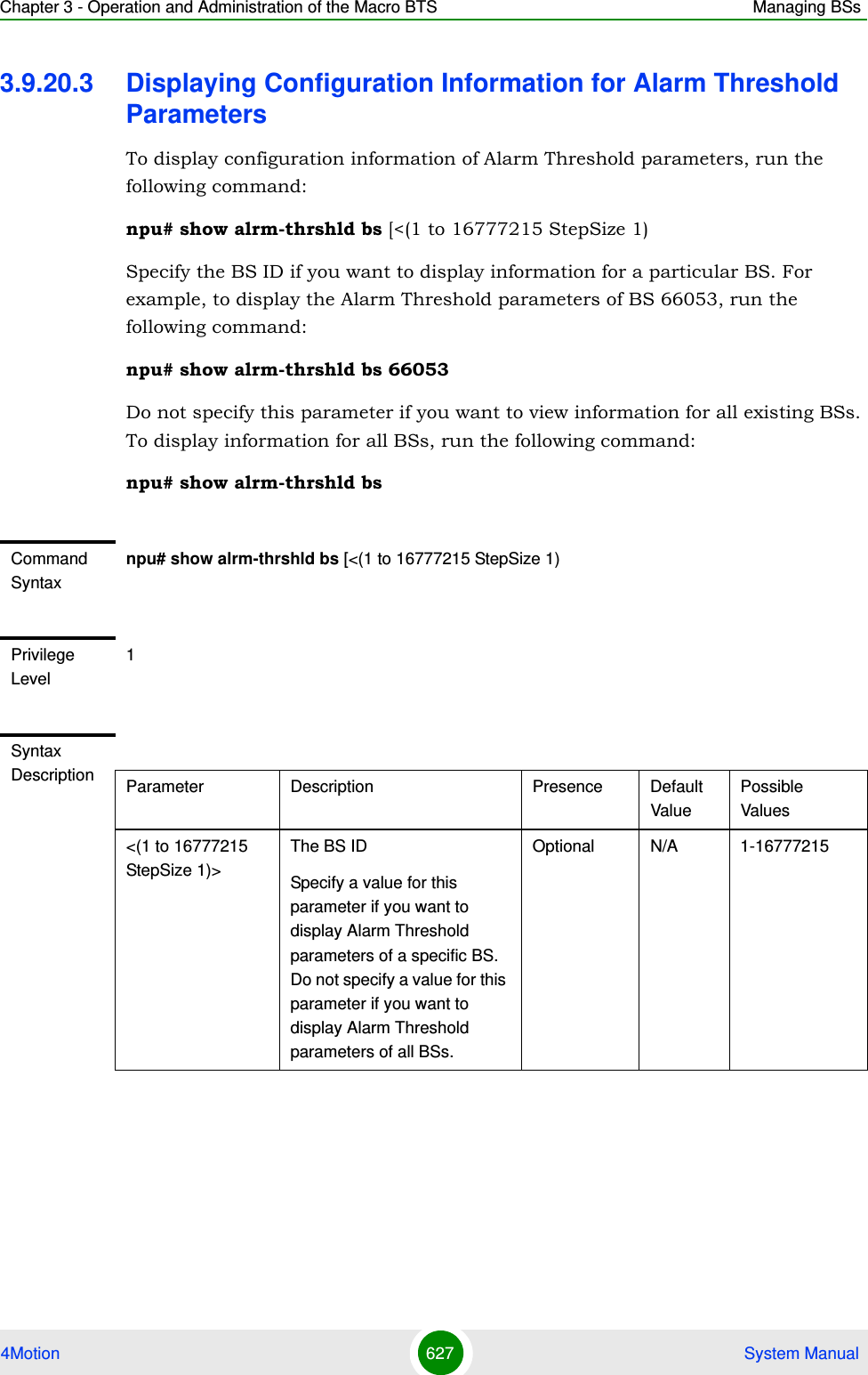
![Chapter 3 - Operation and Administration of the Macro BTS Managing BSs4Motion 628 System Manual3.9 .21 Managing BS Rese r ve d Pa rameters3.9 .22 Managing the BS Ke e p-Alive Functionalit yOnce an MS enters the network, its context is stored in ASN entities (BS, ASN-GW). Dynamically, MS context could be transferred/updated (during HO and re-authentication) to other entities or duplicated to other entities (separation between anchor functions such as Authenticator, Data Path and Relay Data Path).Display Format(for each existing BS if requested for all BSs)BSIDLSB :<value>UplinkMedNoiseUplink99%Noise(dBm) :<value>ThresholdforExcessiveDLDroppedPacketsRatioBestEffort:<value>ThresholdforExcessiveDLDroppedPacketsRatioRealTime:<value>ThresholdforExcessiveDLDroppedPacketsRatioNonRealTime:<value>ThresholdforExcessiveDLDroppedPacketsRatioUgs :<value>ThresholdforExcessiveDLDroppedPacketsRatioErt :<value>Command ModesGlobal command modeNOTEThe BS reserved parameters table enables configuring up to 21 parameters that are reserved for possible future use. In the current release none of the reserved parameters is being used. Therefore, the following commands are not applicable:Configure reserved parameters: npu (config-bs-<N>)# bs-reserved [reserved-1 <string (32)> ] [reserved-2 <string (32)> ] [reserved-3 <string (32)> ] [reserved-4 <string (32)> ] [reserved-5 <string (32)> ] [reserved-6 <string (32)> ] [reserved-7 <string (32)> ] [reserved-8 <string (32)> ] [reserved-9 <string (32)> ] [reserved-10 <string (32)> ] [reserved-11 <string (32)> ] [reserved-12 <string (32)> ] [reserved-13 <string (32)> ] [reserved-14 <string (32)> ] [reserved-15 <string (32)> ] [reserved-16 <string (32)> ] [reserved-17 <string (32)> ] [reserved-18 <string (32)> ] [reserved-19 <string (32)> ] [reserved-20 <string (32)> ] [reserved-21 <string (32)> ].Restore default values of reserved parameters: npu(config-bs-<N>)# no bs-reserved [reserved-1 ] [reserved-2 ] [reserved-3 ] [reserved-4 ] [reserved-5 ] [reserved-6 ] [reserved-7 ] [reserved-8 ] [reserved-9 ] [reserved-10 ] [reserved-11 ] [reserved-12 ] [reserved-13 ] [reserved-14 ] [reserved-15 ] [reserved-16 ] [reserved-17 ] [reserved-18 ] [reserved-19 ] [reserved-20 ] [reserved-21 ].Display configured values of reserved parameters: npu# show bs-reserved bs [<(1 to 16777215 StepSize 1).](https://usermanual.wiki/Alvarion-Technologies/MICRO-25.Manual-p5/User-Guide-1329246-Page-81.png)
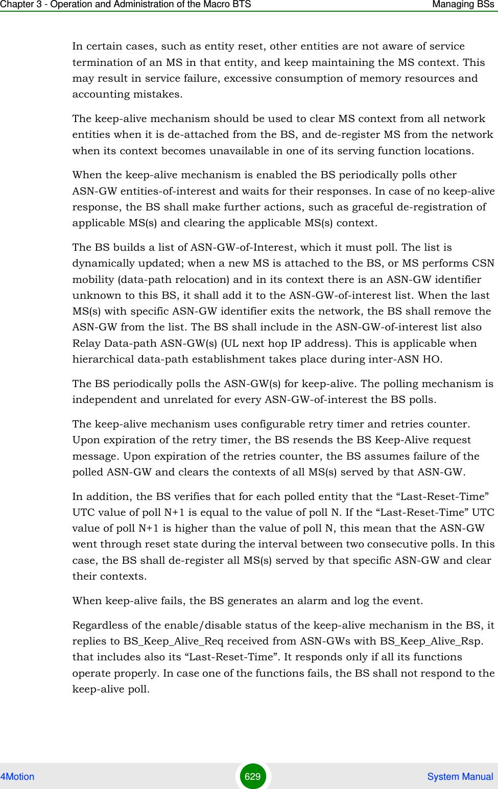
![Chapter 3 - Operation and Administration of the Macro BTS Managing BSs4Motion 630 System Manual3.9.22.1 Configuring BS Keep-Alive ParametersTo configure one or several keep-alive parameters, run the following command:npu(config-bs-66053)# keep-alive [asn-ka {enable | disable} ] [period <(10 to 1000 StepSize 1)> ] [rtx-cnt <(0 to 10 StepSize 1)> ] [rtx-time <(5000 to 10000 StepSize 1)> ]IMPORTANTAn error may occur if you provide an invalid value for any of these parameters. Refer to the syntax description for more information about the appropriate values and format for configuring these parameters.An error may occur if you provide configuration values that do not satisfy following condition: 'period*1000 >= rtx-time * (rtx-cnt + 1)'"At least one parameter must be specified (the value is optional): The command npu(config-bs-66053)# keep-alive will return an Incomplete Command error.Command Syntaxnpu(config-bs-66053)# keep-alive [asn-ka {enable | disable} ] [period <(10 to 1000 StepSize 1)> ] [rtx-cnt <(0 to 10 StepSize 1)> ] [rtx-time <(5000 to 10000 StepSize 1)> ] Privilege Level10Syntax Description Parameter Description Presence Default ValuePossible Values[asn-ka {enable | disable} ]Enable/Disable the BS keep-alive mechanism.Optional disable enabledisable[period <(10 to 1000 StepSize 1)> ]The period in seconds between polling sessions.period x 1000 (value in milliseconds) cannot be lower than (rtx-cnt ) x rtx-time+1).Optional 60 10-1000[rtx-cnt <(0 to 10 StepSize 1)> ]Maximum number of retries if rtx-time has expired without getting a response.Optional 5 0-10](https://usermanual.wiki/Alvarion-Technologies/MICRO-25.Manual-p5/User-Guide-1329246-Page-83.png)
![Chapter 3 - Operation and Administration of the Macro BTS Managing BSs4Motion 631 System Manual3.9.22.2 Displaying Configuration Information for BS Keep-Alive Parameters To display the BS keep-alive parameters, run the following command:npu# show keep-alive bs [<(1 to 16777215 StepSize 1)[rtx-time <(5000 to 10000 StepSize 1)> ]Time in milliseconds to wait for a response before initiating another polling attempt or reaching a decision that the polled entity has failed (if the maximum number of retries set by rtx-cnt has been reached).Optional 5000 5000-10000Command Modesbs configuration modeCommand Syntaxnpu# show keep-alive bs (<(1 to 16777215 StepSize 1)Privilege Level1Syntax Description Parameter Description Presence Default ValuePossible Values<(1 to 16777215 StepSize 1)>The BS ID Specify a value for this parameter if you want to display the Keep-Alive parameters of a specific BS. Do not specify a value for this parameter if you want to display the Keep-Alive parameters of all BSs.Optional N/A 1-16777215](https://usermanual.wiki/Alvarion-Technologies/MICRO-25.Manual-p5/User-Guide-1329246-Page-84.png)
![Chapter 3 - Operation and Administration of the Macro BTS Managing BSs4Motion 632 System Manual3.9 .23 Managing the BS Idle Mode ParametersThe single sector Idle Mode capability provides the benefits of MS power savings and manageable total sector active and non active users, together with reduced overhead on the backhaul network.Idle Mode (IM) mechanism allows an MS to become unavailable on the air interface, and thus freeing operational resources and preserving MS power. During IM operation, an MS switch off its transmission and reception capabilities, and becomes available for DL broadcast control messaging, i.e., MS Paging, in a periodically manner. Using paging broadcast, BS can indicate (if necessary) the MS to exit from IM and return into normal operation mode. The paging control message is sent over the DL of a set of BSs simultaneously. This set is called Paging group (PG). In the current release, each Paging Group includes a single BS.During IM, MS performs location updates when moving from one PG to another. While in the same PG, MS does not need to transmit in the UL and can be paged in the DL if there is traffic targeted at it.After enabling the BS configuration mode, you can configure the Idle Mode parameter (refer to Section 3.9.23.1).You can display configuration information for the Idle Mode parameter of a selected or all existing BSs (refer to Section 3.9.23.2).3.9.23.1 Configuring the BS Idle Mode ParameterFrom the BS configuration mode, run the following command:npu(config-bs-66053)# idle-mode [paging-group-id <(0 to 65535 StepSize 1)> ] Display FormatBSIDLSB Keep Alive ConfigurationASN-KA : <enable/disable>Period (sec) : <value>Retransmissions Count : <value>Retransmission Time : <value>Command ModesGlobal command modeTo configure the BS Idle Mode Parameter:](https://usermanual.wiki/Alvarion-Technologies/MICRO-25.Manual-p5/User-Guide-1329246-Page-85.png)
![Chapter 3 - Operation and Administration of the Macro BTS Managing BSs4Motion 633 System Manual3.9.23.2 Displaying Configuration Information for the BS Idle Mode ParameterTo display configuration information of the BS Idle Mode parameter of a specific or all BSs, run the following command:npu# show idle-mode bs [<(1 to 16777215 StepSize 1)>]Specify the BS ID (1-16777215) of an existing BS if you want to display configuration information for a particular BS. Do not specify values for this parameter if you want to view configuration information for all existing BSs.Command Syntaxnpu(config-bs-66053)# idle-mode [paging-group-id <(0 to 65535 StepSize 1)>] Privilege Level10Syntax Description Parameter Description Presence Default ValuePossible Values[paging-group-id <(0 to 65535 StepSize 1)> ]The Paging Group ID of the BS.0 means that Idle Mode is disabled.If other than 0 (disable), should be unique in the network (different paging-group for each BS).Mandatory 0 0 to 65535Command Modesbs configuration mode Command Syntaxnpu# show idle-mode bs [<(1 to 16777215 StepSize 1)> ]Privilege Level1](https://usermanual.wiki/Alvarion-Technologies/MICRO-25.Manual-p5/User-Guide-1329246-Page-86.png)
![Chapter 3 - Operation and Administration of the Macro BTS Managing BSs4Motion 634 System Manual3.9 .24 Managing Schedule r Pa ra m e t e rsScheduling uncommitted traffic (above the maximum reserved rate) can be done using one of the following options:Equal Time (ET) scheduling mode, in which air resources are being scheduled in a fair manner proportional to the users' excess traffic (maximum sustained rate - maximum reserved rate) SLAs.Equal Rate (ER) scheduling mode, in which air resources are allocated to users aiming at ensuring data rate fairness between users proportional to their excess traffic SLAs.Assuming a sector with diversity (different channels conditions) of active users, ET scheme enables higher aggregate sector throughput at the expense of data-rate Syntax Description Parameter Description Presence Default ValuePossible Values[<(1 to 16777215 StepSize 1)> ]The BS ID Specify a value for this parameter if you want to display the Idle Mode Paging Group ID Parameter of a specific BS. Do not specify a value for this parameter if you want to display the Idle Mode Paging Group ID Parameter of all BSs.Optional N/A 1-16777215Display Format(for each existing BS if requested for all BSs)BSIDLSB :<value>PagingGrpId :<value>Command ModesGlobal command mode](https://usermanual.wiki/Alvarion-Technologies/MICRO-25.Manual-p5/User-Guide-1329246-Page-87.png)
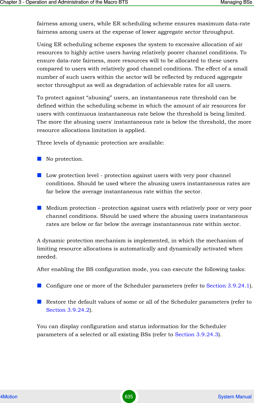
![Chapter 3 - Operation and Administration of the Macro BTS Managing BSs4Motion 636 System Manual3.9.24.1 Configuring Scheduler ParametersFrom the BS configuration mode, run the following command:npu(config-bs-66053)# scheduler [scheduler-mode {equalRate | equalTime} ] [dl-abuse-protection-level {none | low | medium} ] [ul-abuse-protection-level {none | low | medium} ]To apply the changes, run the following command: npu(config-bs-66053)# scheduler-applyTo configure the Scheduler parameters:Command Syntaxnpu(config-bs-66053)# scheduler [scheduler-mode {equalRate | equalTime} ] [dl-abuse-protection-level {none | low | medium} ] [ul-abuse-protection-level {none | low | medium} ]Privilege Level10Syntax Description Parameter Description Presence Default ValuePossible Valuesscheduler-mode {equalRate | equalTime} ]The scheduling scheme for uncommitted data.Optional equalRate equalRateequalTimedl-abuse-protection-level {none | low | medium}The protection level for the downlink for equalRate scheduling mode.Optional none nonelowmediumul-abuse-protection-level {none | low | medium}The protection level for the uplink for equalRate scheduling mode.Optional none nonelowmediumCommand Modesbs configuration mode](https://usermanual.wiki/Alvarion-Technologies/MICRO-25.Manual-p5/User-Guide-1329246-Page-89.png)
![Chapter 3 - Operation and Administration of the Macro BTS Managing BSs4Motion 637 System Manual3.9.24.2 Restoring the Default Values of Scheduler ParametersTo restore the default values of some or all of the Scheduler parameters, run the following command:npu(config-bs-66053)# no scheduler [scheduler-mode ] [dl-abuse-protection-level ] [ul-abuse-protection-level ]You can restore only some parameters to the default values by specifying only those parameter. For example, to restore only the ul-abuse-protection-level parameter to the default value, run the following command:npu(config-bs-66053)# no scheduler ul-abuse-protection-levelThis parameter will be restored to its default value, while the other parameters will remain unchanged.To restore all parameters to their default value, run the following command:npu(config-bs-66053)# no schedulerTo apply the changes, run the following command: npu(config-bs-66053)# scheduler-apply3.9.24.3 Displaying Configuration Information for Scheduler ParametersTo display configuration information of Scheduler parameters, run the following command:npu# show scheduler bs [<(1 to 16777215 StepSize 1)NOTERefer to Section 3.9.24.1 for a description and default values of these parameters.Command Syntaxnpu(config-bs-66053)# no scheduler [scheduler-mode ] [dl-abuse-protection-level ] [ul-abuse-protection-level ]Privilege Level10Command Modesbs configuration mode](https://usermanual.wiki/Alvarion-Technologies/MICRO-25.Manual-p5/User-Guide-1329246-Page-90.png)
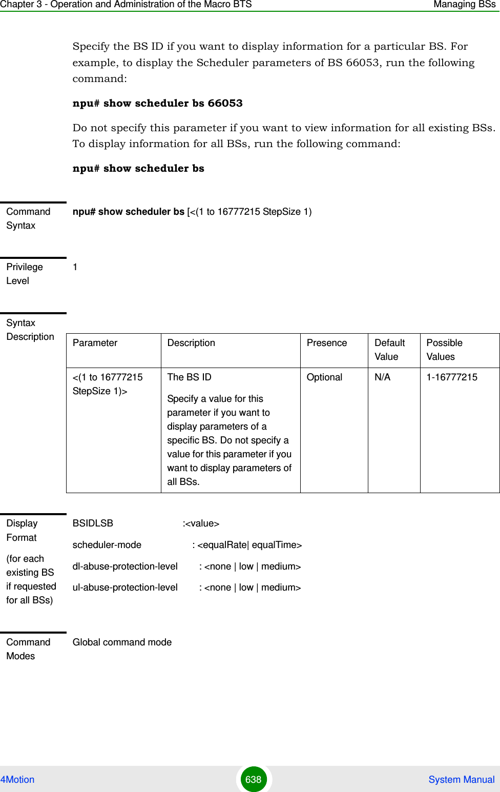
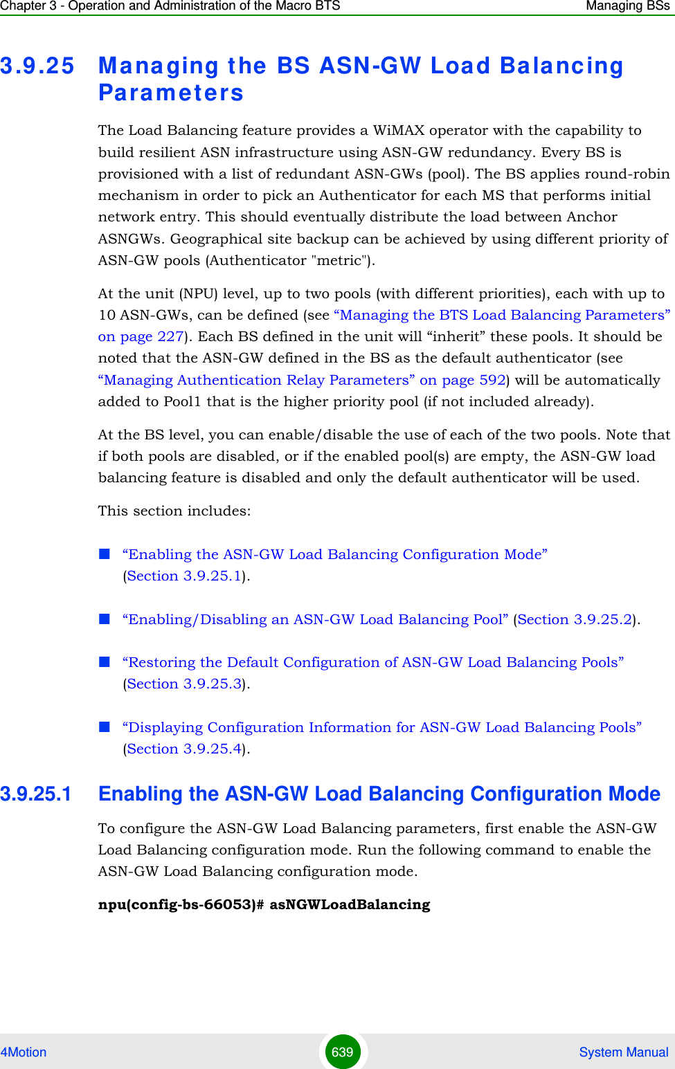
![Chapter 3 - Operation and Administration of the Macro BTS Managing BSs4Motion 640 System Manual3.9.25.2 Enabling/Disabling an ASN-GW Load Balancing PoolAfter enabling the ASN-GW Load Balancing configuration mode, run the following command to enable/disable ASN-GW load balancing pools:npu(config-bs-5-ASNGWLoadBalancing)# asNGWLoadBalancing [asn-gw-pool-1 {enable | disable} ] [asn-gw-pool-2 {enable| disable} ]Note: After enabling Pool 1 and/or Pool 2, the AU must be reset to apply the change.Command Syntaxnpu(config-bs-66053)# asNGWLoadBalancingPrivilege Level10Command Modesbs configuration modeCommand Syntaxnnpu(config-bs-5-ASNGWLoadBalancing)# asNGWLoadBalancing [asn-gw-pool-1 {enable | disable} ] [asn-gw-pool-2 {enable| disable} ] Privilege Level10Syntax Description Parameter Description Presence Default ValuePossible Values[asn-gw-pool-1 {enable | disable} ]Enable/disable the use of pool 1Optional Enable EnableDisable[asn-gw-pool-2 {enable | disable} ]Enable/disable the use of pool 2.Pool 2 cannot be enabled if Pool 1 is disabled.Optional Enable EnableDisableCommand Modesbs asn-gw load balancing configuration mode](https://usermanual.wiki/Alvarion-Technologies/MICRO-25.Manual-p5/User-Guide-1329246-Page-93.png)
![Chapter 3 - Operation and Administration of the Macro BTS Managing BSs4Motion 641 System Manual3.9.25.3 Restoring the Default Configuration of ASN-GW Load Balancing PoolsAfter enabling the ASN-GW Load Balancing configuration mode, run the following command to restore the default configuration of ASN-GW load balancing pools:npu(config-bs-5-ASNGWLoadBalancing)# no ASNGWLoadBalancing [asn-gw-pool-1 ] [asn-gw-pool-2 ] Specify a pool to restore the configuration of this pool to the default value (enabled).Do not specify any pool to restore the configuration of both pools to the default value (enabled).3.9.25.4 Displaying Configuration Information for ASN-GW Load Balancing PoolsTo display configuration information of ASN-GW Load Balancing Pool, run the following command:Command Syntaxnpu(config-bs-5-ASNGWLoadBalancing)# no ASNGWLoadBalancing [asn-gw-pool-1 ] [asn-gw-pool-2 ]Privilege Level10Syntax Description Parameter Description Presence Default ValuePossible Values[asn-gw-pool-1 ] Specify pool 1 to return the configuration of this pool to the default value (enabled)Optional N/A asn-gw-pool-1[asn-gw-pool-2 ] Specify pool 2 to return the configuration of this pool to the default value (enabled)Optional N/A asn-gw-pool-2Command Modesbs asn-gw load balancing configuration mode](https://usermanual.wiki/Alvarion-Technologies/MICRO-25.Manual-p5/User-Guide-1329246-Page-94.png)
![Chapter 3 - Operation and Administration of the Macro BTS Managing BSs4Motion 642 System Manualnpu# show ASNGWLoadBalancing bs [<(1 to 16777215 StepSize 1)> ]Specify the BS ID if you want to display information for a particular BS. For example, to display the ASN-GW Load Balancing configuration parameters of BS 66053, run the following command:npu# show ASNGWLoadBalancing bs 66053Do not specify this parameter if you want to view information for all existing BSs. To display information for all BSs, run the following command:npu# show ASNGWLoadBalancing bs3.9 .26 Managing Beam Forming ParameterThe Beam Forming Calibration Attenuator parameter is applicable only if the Downlink Diversity Mode parameter is set to Beam Forming (see “Configuring the Airframe Downlink Diversity Mode Parameter” on page 568).3.9.26.1 Enabling the Beam Forming Configuration ModeFrom the BS configuration mode, run the following command:npu(config-bs-66053)# beamformCommand SyntaxASNGWLoadBalancing bs [<(1 to 16777215 StepSize 1)> ]Privilege Level1Display Format (for each existing BS if requested for all BSs)BSIDLSB : <value>ASN-GWPoolPrimary : <enable(1)/disable(2)>ASN-GWPoolSecondary : <enable(1)/disable(2)>Command ModesGlobal command modeTo enable the Beam Forming Configuration Mode:](https://usermanual.wiki/Alvarion-Technologies/MICRO-25.Manual-p5/User-Guide-1329246-Page-95.png)
![Chapter 3 - Operation and Administration of the Macro BTS Managing BSs4Motion 643 System ManualAfter enabling the Beam Forming configuration mode, you can execute the following tasks:Configure the Beam Forming parameter (refer to Section 3.9.26.2).Restore the default values of the Beam Forming parameter (refer to Section 3.9.26.3).You can display configuration value for the beamforming parameter of a selected or all existing BSs (refer to Section 3.9.26.4).3.9.26.2 Configuring the Beam Forming ParameterFrom the beamforming configuration mode, run the following command:npu(config-bs-66053-beamform)# beamform [cal-atten {noAttenUsed | lowAtten | highAtten} ] To configure the Beam Forming parameter:Command Syntaxnpu(config-bs-66053)# beamform [cal-atten {noAttenUsed | lowAtten | highAtten} ] Privilege Level10Syntax Description Parameter Description Presence Default ValuePossible Valuescal-atten {noAttenUsed | lowAtten | highAttenApplicable only in Beam Forming DL Diversity Mode. The calibration attenuation used to help mitigate potential out of band interference to beam forming calibration caused by other base stations.Optional lowAtten noAttenUsedlowAttenhighAttenCommand Modesbs beamform configuration mode](https://usermanual.wiki/Alvarion-Technologies/MICRO-25.Manual-p5/User-Guide-1329246-Page-96.png)
![Chapter 3 - Operation and Administration of the Macro BTS Managing BSs4Motion 644 System Manual3.9.26.3 Restoring the Default Value of the Beam Forming ParameterTo restore the default values of the Beam Forming parameters, run the following command:npu(config-bs-66053)# no beamform [cal-atten ]3.9.26.4 Displaying Configuration Information for Beam Forming ParameterTo display configuration information of the Beam Forming parameters, run the following command:npu# show beamform bs [<(1 to 16777215 StepSize 1)Specify the BS ID if you want to display information for a particular BS. For example, to display the Beam Forming parameter of BS 66053, run the following command:npu# show beamform bs 66053Do not specify this parameter if you want to view information for all existing BSs. To display information for all BSs, run the following command:npu# show beamform bsCommand Syntaxnpu(config-bs-66053)# no beamform [cal-atten ]Privilege Level10Command Modesbs beamform configuration modeCommand Syntaxnpu# show beamform bs [<(1 to 16777215 StepSize 1)Privilege Level1](https://usermanual.wiki/Alvarion-Technologies/MICRO-25.Manual-p5/User-Guide-1329246-Page-97.png)
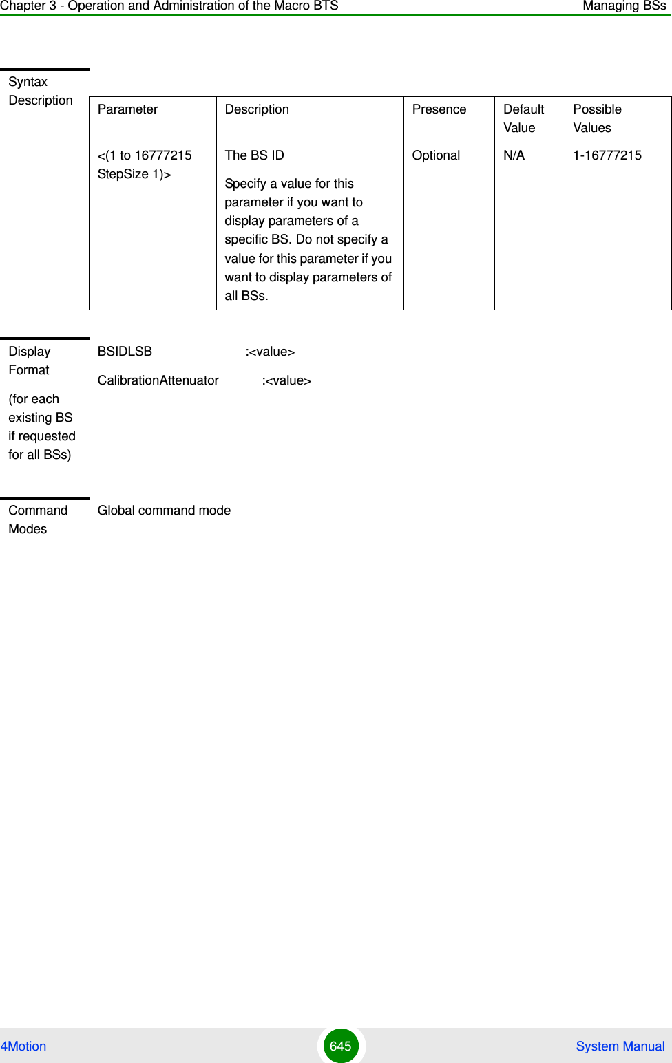
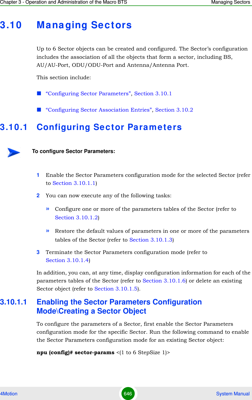
![Chapter 3 - Operation and Administration of the Macro BTS Managing Sectors4Motion 647 System ManualTo create a new Sector object, the width parameter must be specified. Run the following command to create a new Sector object and enable the parameters configuration mode for this ODU:npu (config)# sector-params <(1 to 6 StepSize 1)> [width <(0 to 359 StepSize 1)>]A new Sector object is created with default values for all parameters except to the mandatory width parameter.For example, to create Sector 1 object and enable the parameters configuration mode for this Sector, where the width is 90 degrees, run the following command:npu (config)# sector-params 1 width 90After enabling the Sector Parameters configuration mode for a Sector you can execute any of the following tasks:Configure one or more of the parameters tables of the Sector (refer to Section 3.10.1.2)Restore the default values of non-mandatory parameters in one or more of the parameters tables of the Sector (refer to Section 3.10.1.3)After executing the above tasks, you can terminate the Sector Parameters configuration mode (refer to Section 3.10.1.4) and return to the global configuration mode.IMPORTANTAn error may occur if you provide an invalid value for any of these parameters. Refer the syntax description for more information about the appropriate values and format for configuring these parameters.Command Syntaxnpu (config)# sector-params <(1 to 6 StepSize 1)> [ width <(0 to 359 StepSize 1)> ]Privilege Level10Syntax Description Parameter Description Presence Default ValuePossible Values](https://usermanual.wiki/Alvarion-Technologies/MICRO-25.Manual-p5/User-Guide-1329246-Page-100.png)
![Chapter 3 - Operation and Administration of the Macro BTS Managing Sectors4Motion 648 System Manual3.10.1.2 Configuring Sector ParametersAfter enabling the Sector Parameters configuration mode you can configure the following parameters tables:Sector Definition (refer to Section 3.10.1.2.1)Sector Reserved (refer to Section 3.10.1.2.2)3.10.1.2.1 Configuring Sector Definition ParametersThe Sector Definition table enables configuring the main properties of the Sector.To configure the Sector Definition parameters, run the following command:npu(config-sector-params-1)# sector-definition [sector-name <string (32)>] [heading <(0 to 359 StepSize 1)>] [width <(0 to 359 StepSize 1)>]<(1 to 6 StepSize 1)> The Sector ID Mandatory N/A 1-6width <(0 to 359 StepSize 1)>The planned sector coverage, in degrees.Mandatory when creating a new SectorN/A 0 - 359Command ModesGlobal configuration modeNOTEThe following examples are for sector-1 parameters configuration mode.IMPORTANTAn error may occur if you provide an invalid value for any of these parameters. Refer the syntax description for more information about the appropriate values and format for configuring these parameters.Command Syntaxnpu(config-sector-params-1)# sector-definition [sector-name <string (32)> ] [heading <(0 to 359 StepSize 1)> ] [width <(0 to 359 StepSize 1)> ]Privilege Level10](https://usermanual.wiki/Alvarion-Technologies/MICRO-25.Manual-p5/User-Guide-1329246-Page-101.png)
![Chapter 3 - Operation and Administration of the Macro BTS Managing Sectors4Motion 649 System Manual3.10.1.2.2 Configuring Sector Reserved ParametersAs the name implies, the reserved parameters table enables configuring up to 4 parameters that are reserved for possible future use. In the current release none of the reserved parameters is being used.To configure the Sector Reserved parameters, run the following command:npu(config-sector-params-1)# sector-reserved [reserved-1 <string (32)>] [reserved-2 <string (32)>] [reserved-3 <string (32)>] [reserved-4 <string (32)>].Syntax Description Parameter Description Presence Default ValuePossible Valuessector-name <string (32)>The sector name (description). Must be unique in the site (shelf).Optional null (empty string)A string of up to 32 charactersheading <(0 to 359 StepSize 1)>The sector heading (The center angle of the sector), in degrees.Optional 0 0 - 359width <(0 to 359 StepSize 1)>The planned sector coverage, in degrees.Optional Configured previously during sector creation.0 - 359Command Modessector-params configuration modeCommand Syntaxnpu (config-sector-params-1)# sector-reserved [reserved-1 <string (32)>] [reserved-2 <string (32)>] [reserved-3 <string (32)>] [reserved-4 <string (32)>]Privilege Level10](https://usermanual.wiki/Alvarion-Technologies/MICRO-25.Manual-p5/User-Guide-1329246-Page-102.png)
![Chapter 3 - Operation and Administration of the Macro BTS Managing Sectors4Motion 650 System Manual3.10.1.3 Restoring Default Values for Sector Configuration ParametersAfter enabling the Sector Parameters configuration mode you can restore the default values for parameters in the following parameters tables:Sector Definition (refer to Section 3.10.1.3.1)Sector Reserved (refer to Section 3.10.1.3.2)3.10.1.3.1 Restoring the Default Values of Sector Definition ParametersTo restore the one or all of the non-mandatory parameters to the default values, run the following command:npu(config-sector-params-1)# no sector-definition [sector-name] [heading]Run the following command to restore the sector definition parameters to the default values: npu(config-sector-params-1)# no sector-definitionSyntax Description Parameter Description Presence Default ValuePossible Values[reserved-N <string (32)>] (N=1-4)Reserved parameter number N Optional null (an empty string)A string of 32 printable characters.Command Modessector-params configuration modeNOTERefer to Section 3.10.1.2.1 for a description and default values of these parameter.Command Syntaxnpu(config-sector-params-1)# no sector-definition [sector-name] [heading]Privilege Level10](https://usermanual.wiki/Alvarion-Technologies/MICRO-25.Manual-p5/User-Guide-1329246-Page-103.png)
![Chapter 3 - Operation and Administration of the Macro BTS Managing Sectors4Motion 651 System Manual3.10.1.3.2 Restoring the Default Values of Sector Reserved ParametersTo restore Sector Reserved parameters to their default value, run the following command:npu(config-sector-params-1)# no sector-reserved [reserved-1] [reserved-2] [reserved-3] [reserved-4]You can restore only selected parameters to their default value by specifying only those parameter. For example, to restore only the reserved-1 parameter to its default values, run the following command:npu(config-sector-params-1)# no sector-reserved reserved-1This parameter will be restored to the default value, while the other parameters will remain unchanged.To restore all parameters to their default value, run the following command:npu(config-sector-params-1)# no sector-reserved3.10.1.4 Terminating the Sector Parameters Configuration ModeRun the following command to terminate the Sector Parameters configuration mode:npu(config-sector-params-1)# exitCommand Modessector-params configuration modeNOTERefer to Section 3.10.1.2.2 for a description and default values of these parameters.Command Syntaxnpu(config-sector-params-1)# no sector-reserved [reserved-1] [reserved-2] [reserved-3] [reserved-4]Privilege Level10Command Modessector-params configuration mode](https://usermanual.wiki/Alvarion-Technologies/MICRO-25.Manual-p5/User-Guide-1329246-Page-104.png)
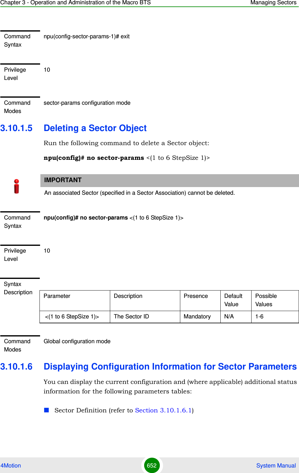
![Chapter 3 - Operation and Administration of the Macro BTS Managing Sectors4Motion 653 System ManualSector Reserved (refer to Section 3.10.1.6.2)3.10.1.6.1 Displaying Configuration Information for Sector Definition ParametersTo display configuration information for the Sector Definition parameters of a specific or all Sector objects, run the following command:npu# show sector-definition [sector-id <(1 to 6 StepSize 1)>]Specify the Sector ID (1-6) if you want to display configuration information for a particular Sector. Do not specify a value for this parameter if you want to view configuration information for all existing Sector objects.Command Syntaxnpu# show sector-definition [sector-id <(1 to 6 StepSize 1)> ]Privilege Level1Syntax Description Parameter Description Presence Default ValuePossible Valuessector-id <(1 to 6 StepSize 1)> The Sector ID Specify a value for this parameter if you want to display the Sector Definition parameters of a specific Sector. Do not specify a value for this parameter if you want to display the parameters of all Sectors.Optional N/A 1-6Display Format(for each existing ODU object if requested for all ODUs)SectorID :<value>SectorName :<value>SectorHeading(degrees) :<value>SectorWidth(degrees) :<value>](https://usermanual.wiki/Alvarion-Technologies/MICRO-25.Manual-p5/User-Guide-1329246-Page-106.png)
![Chapter 3 - Operation and Administration of the Macro BTS Managing Sectors4Motion 654 System Manual3.10.1.6.2 Displaying Configuration Information for Sector Reserved ParametersTo display configuration information for the reserved parameters of a specific or all Sector objects, run the following command:npu# show sector-reserved [sector-id <(1 to 6 StepSize 1)>]Specify the Sector ID (1-6) if you want to display configuration for a particular Sector. Do not specify a value for this parameter if you want to view configuration for all existing Sector objects.Command ModesGlobal command modeCommand Syntaxnpu# show sector-reserved [sector-id <(1 to 6 StepSize 1)> ]Privilege Level1Syntax Description Parameter Description Presence Default ValuePossible Values<(1 to 6 StepSize 1)>The Sector ID.Specify a value for this parameter if you want to display the reserved parameters of a specific Sector. Do not specify a value for this parameter if you want to display the reserved parameters of all Sectors.Optional N/A 1-6Display Format(for each existing ODU object if requested for all ODUs)SectorID :<value>ReservedParameter1 :<value>ReservedParameter2 :<value>ReservedParameter3 :<value>ReservedParameter4 :<value>](https://usermanual.wiki/Alvarion-Technologies/MICRO-25.Manual-p5/User-Guide-1329246-Page-107.png)
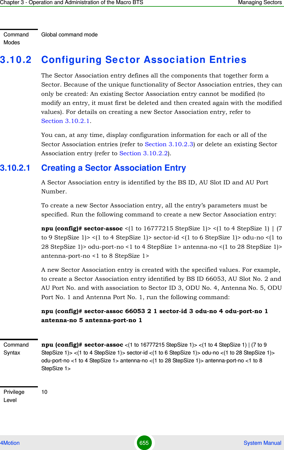
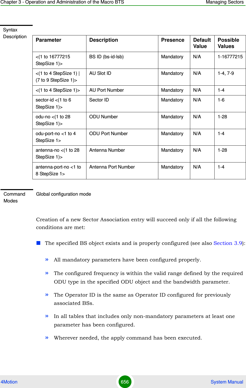
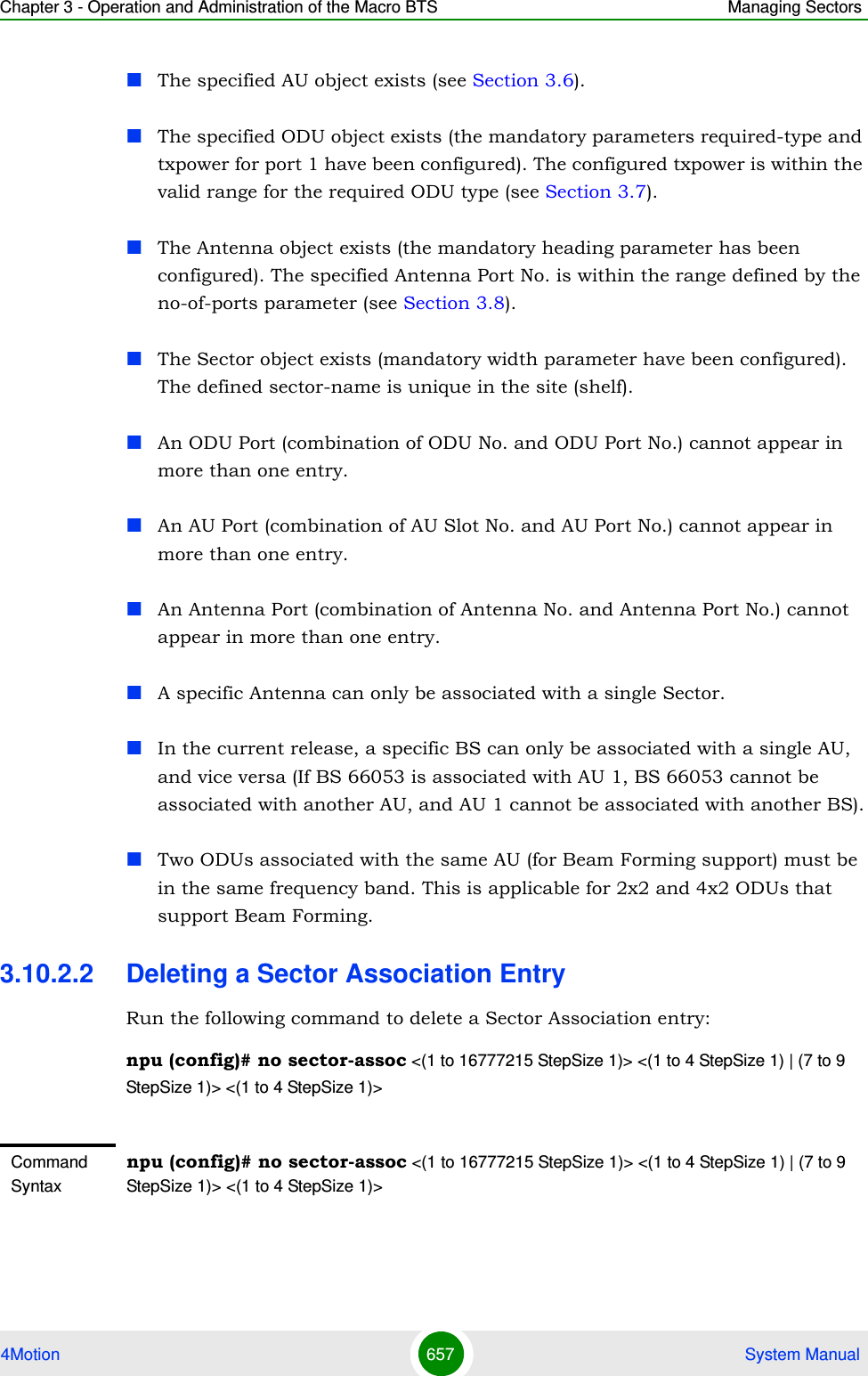
![Chapter 3 - Operation and Administration of the Macro BTS Managing Sectors4Motion 658 System ManualNote that if all Sector Association entries with a particular BS are deleted (meaning the BS is no longer in use), this BS should be removed from all relevant Neighbor BS lists of other BSs.3.10.2.3 Displaying Configuration Information for Sector Association EntriesTo display configuration information of a specific or all Sector Association entries, run the following command:npu# show sector-assoc [bs-id-lsb <(1 to 16777215 StepSize 1)> au-slot-no <(1 to 4StepSize 1) | (7 to 9 StepSize 1)> au-port-no <(1 to 4 StepSize 1)>]Specify the BS ID (bs-id-lsb), AU Slot No. (au-slot-no) and AU Port number (au-port-no) if you want to display configuration information for a particular Sector Association entry. Do not specify values for these parameters if you want to view configuration information for all existing Sector Association entries.Privilege Level10Syntax Description Parameter Description Presence Default ValuePossible Values<(1 to 16777215 StepSize 1)>BS ID (bs-id-lsb) Mandatory N/A 1-16777215<(1 to 4 StepSize 1) | (7 to 9 StepSize 1)>AU Slot ID Mandatory N/A 1-4, 7-9<(1 to 4 StepSize 1)> AU Port Number Mandatory N/A 1-4Command ModesGlobal configuration modeCommand Syntaxnpu# show sector-assoc [bs-id-lsb <(1 to 16777215 StepSize 1)> au-slot-no <(1 to 4StepSize 1) | (7 to 9 StepSize 1)> au-port-no <(1 to 4 StepSize 1)> ]Privilege Level1](https://usermanual.wiki/Alvarion-Technologies/MICRO-25.Manual-p5/User-Guide-1329246-Page-111.png)
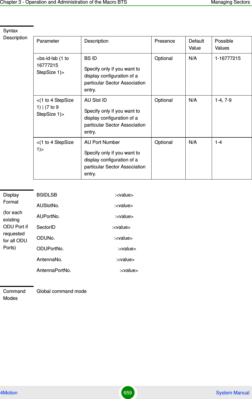
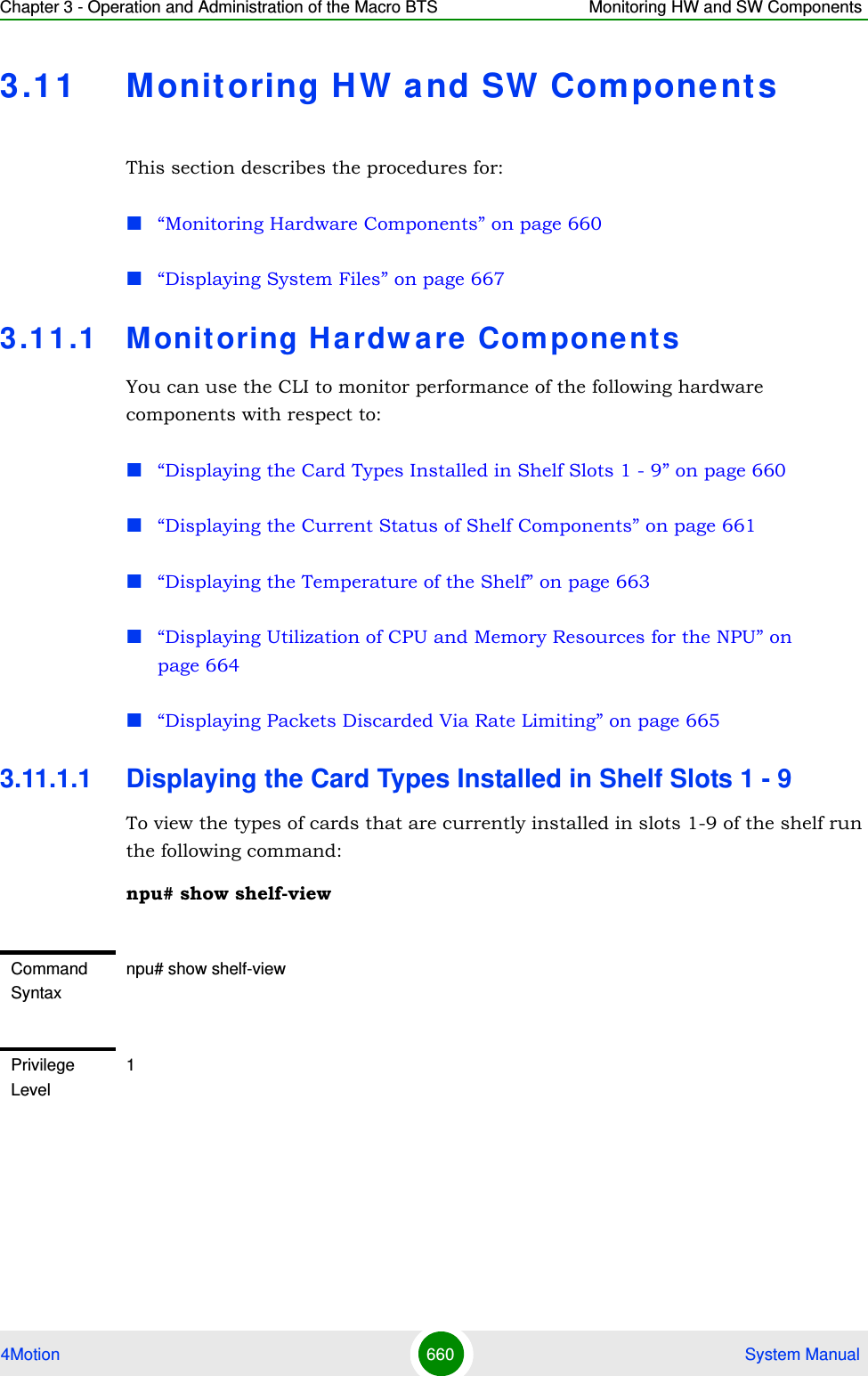
![Chapter 3 - Operation and Administration of the Macro BTS Monitoring HW and SW Components4Motion 661 System Manual3.11.1.2 Displaying the Current Status of Shelf ComponentsYou can view the current status of the following shelf components:NPUPSUPIUAVU or (specific fan)To view the current status of all shelf components, run the following command:npu# show shelf status [{NPU | PSU [<slot id (1-4)>] |PIU [<slot id (1-2)>] | AVU | Fan [<fan_num (1-10)>]}]For example, run the following command to view the status of the PSU, slot# 4:npu# show shelf status PSU 4To view the status of all the shelf components, run the following command:Display Format Slot# Card Type 1 <notInstalled/au4x4Modem/other> 2 <notInstalled/au4x4Modem/other> 3 <notInstalled/au4x4Modem/other> 4 <notInstalled/au4x4Modem/other> 5 npu 6 notInstalled 7 <notInstalled/au4x4Modem/other> 8 <notInstalled/au4x4Modem/other> 9 <notInstalled/au4x4Modem/other>Command ModesGlobal command modeNOTERefer Figure 3-1 for more information about the slot IDs assigned to each shelf component.](https://usermanual.wiki/Alvarion-Technologies/MICRO-25.Manual-p5/User-Guide-1329246-Page-114.png)
![Chapter 3 - Operation and Administration of the Macro BTS Monitoring HW and SW Components4Motion 662 System Manualnpu# show shelf statusThe displayed information includes the following details:NPU:»Slot#: 5»PrsntState: Installed»HWVersion:»HWRevision:»SerialNumAVU»PrsntState: Installed/Not Installed»HlthState:Healthy/FaultyCommand Syntaxnpu# show shelf status [{NPU | PSU [<slot id (1-4)>] |PIU [<slot id (1-2)>] | AVU | Fan [<fan_num (1-10)>]}]Privilege Level1Syntax Description Parameter Description Presence Default ValuePossible Values[{NPU | PSU [<slot id (1-4)>] |PIU [<slot id (1-2)>] | AVU | Fan [<fan_num (1-10)>]}Indicates the shelf components for which you want to display the current status. Do not specify any component to view the status of all components.Optional N/A NPUPSU <1-4>PIU <1-2>AVUFan <(1-10>](https://usermanual.wiki/Alvarion-Technologies/MICRO-25.Manual-p5/User-Guide-1329246-Page-115.png)
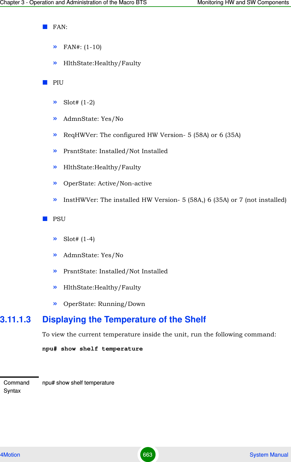
![Chapter 3 - Operation and Administration of the Macro BTS Monitoring HW and SW Components4Motion 664 System Manual3.11.1.4 Displaying Utilization of CPU and Memory Resources for the NPUTo display the utilization of CPU and memory resources for the NPU, run the following command:npu# show resource usageAfter you run this command, the current CPU and memory usage is displayed.Privilege Level1Display FormatCurrent shelf temperature: <value> [Celsius] / <value> [Farenheit]Command ModesGlobal command modeNOTEFor more information about setting thresholds for CPU and memory usage, refer to “Displaying CPU and Memory Utilization Limits for the NPU” on page 173.Command Syntaxnpu# show resource usagePrivilege Level1Display FormatResource Usage[in %]CPU <value>Memory 7<value>Command ModesGlobal command mode](https://usermanual.wiki/Alvarion-Technologies/MICRO-25.Manual-p5/User-Guide-1329246-Page-117.png)
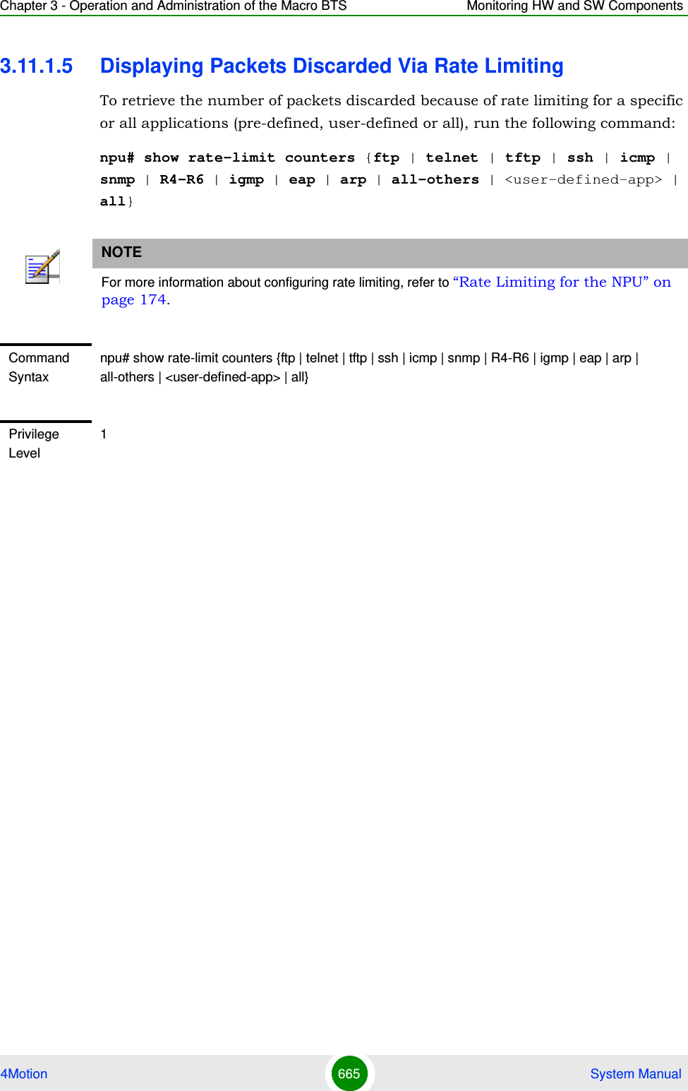
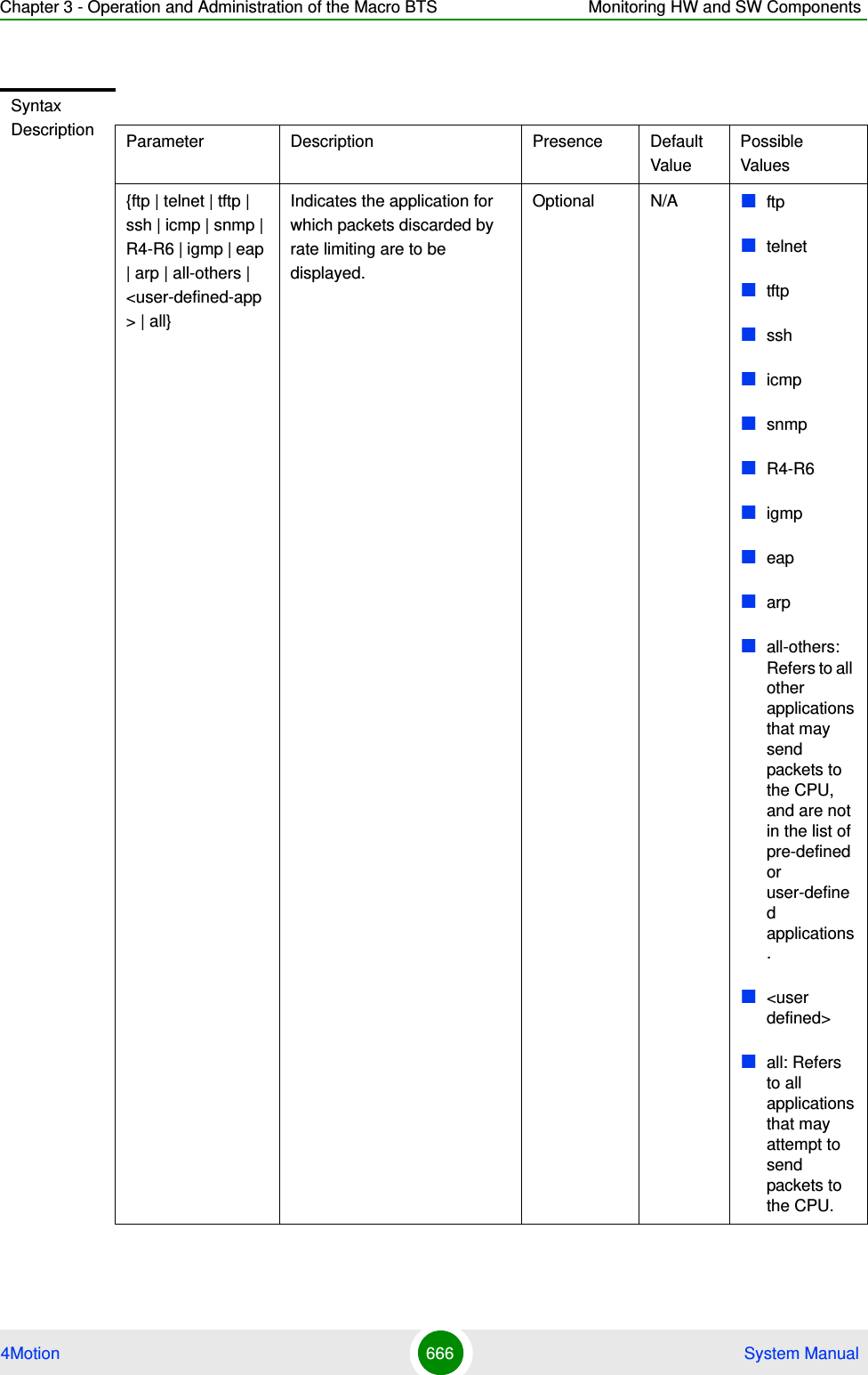
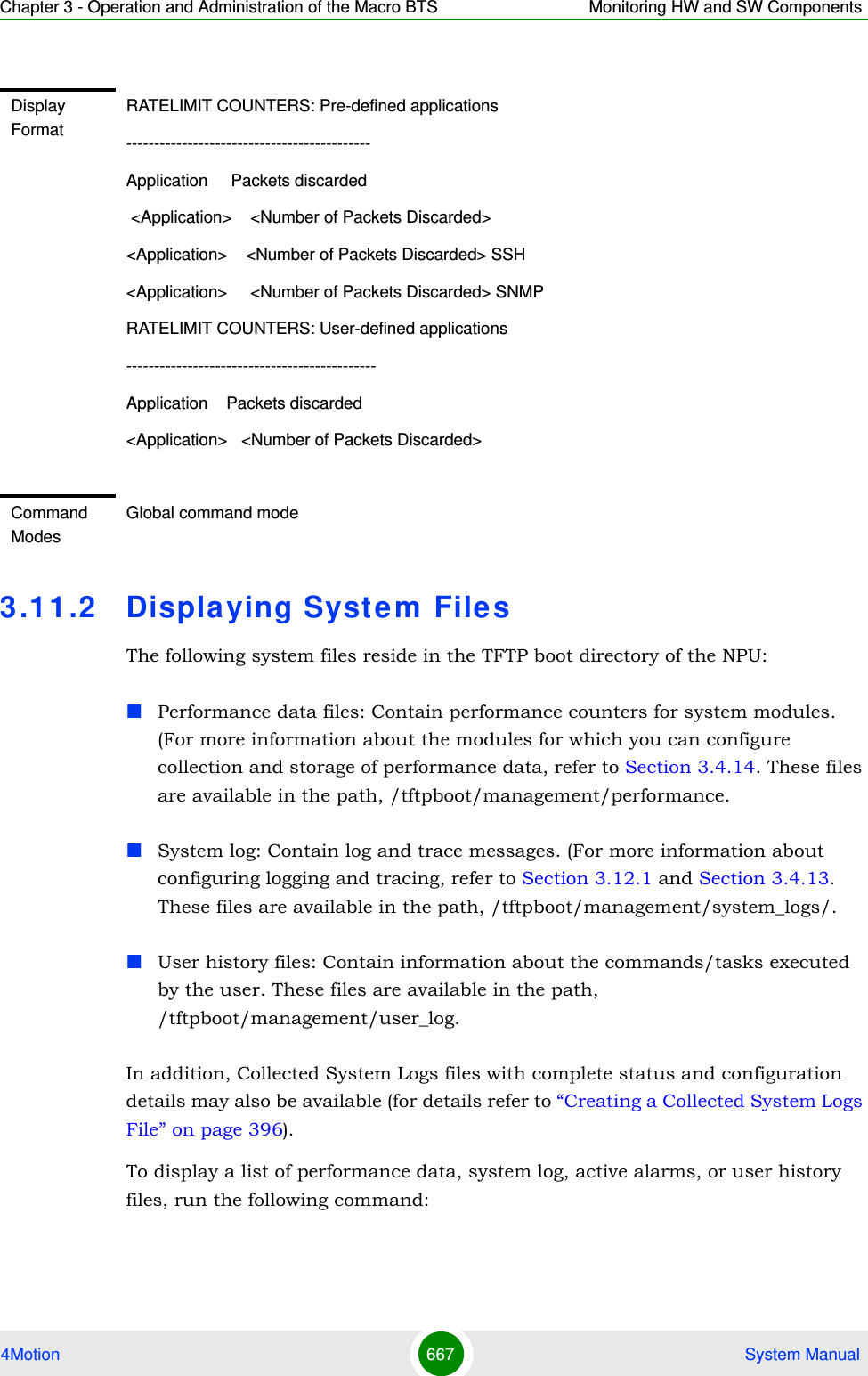
![Chapter 3 - Operation and Administration of the Macro BTS Monitoring HW and SW Components4Motion 668 System Manualnpu# show saved {Performance | Active-alarm | Log | User-history} files [recent <1-65535>]For example, if you want to view the 30 most recently saved log files, residing in the TFTP boot directory of the NPU, run the following command:npu# show saved Log files recent 30To display a list of collected system logs files, run the following command:npu# show saved system logsCommand Syntaxnpu# show saved {Performance | Active-alarm | Log | User-history} files [recent <1-65535>]Privilege Level1Syntax Description Parameter Description Presence Default ValuePossible ValuesPerformance|Active-alarm|Log|User-historyIndicates the type of system files that are to be displayed:Mandatory N/A PerformanceActive-alarmLogUser-history[recent <1-65535>]Indicates the number of files to be displayed. The most recently saved files are displayed.If you do not specify a value for this parameter, all the files of a particular type are displayed.Optional N/A 1-65355Command ModesGlobal command modeCommand Syntaxnpu# show saved system logs](https://usermanual.wiki/Alvarion-Technologies/MICRO-25.Manual-p5/User-Guide-1329246-Page-121.png)
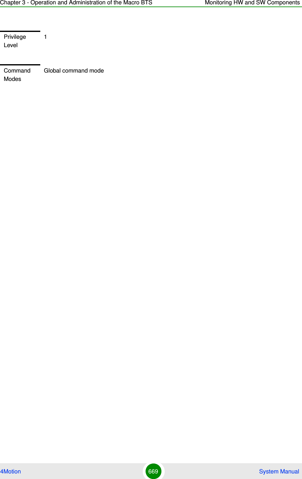

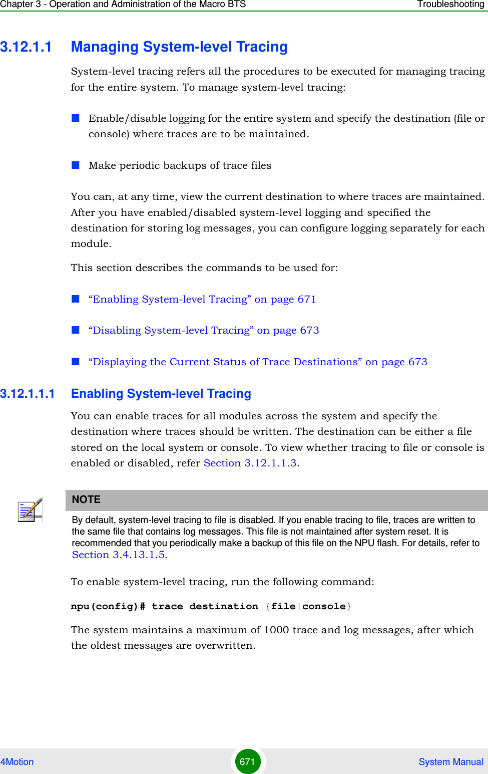
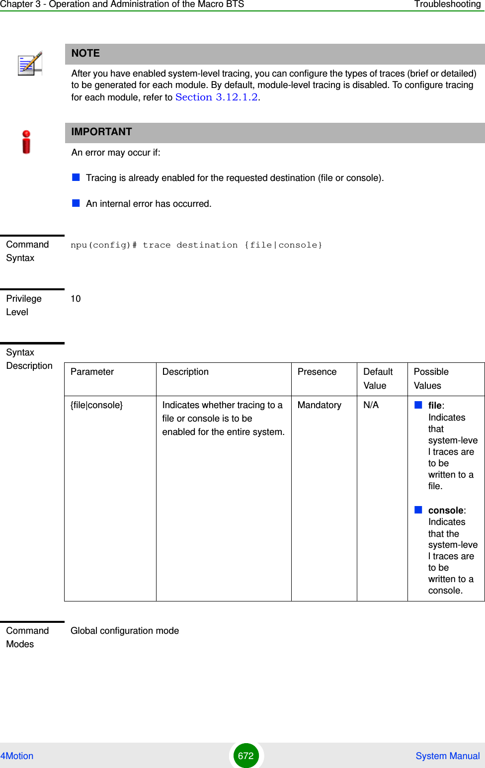
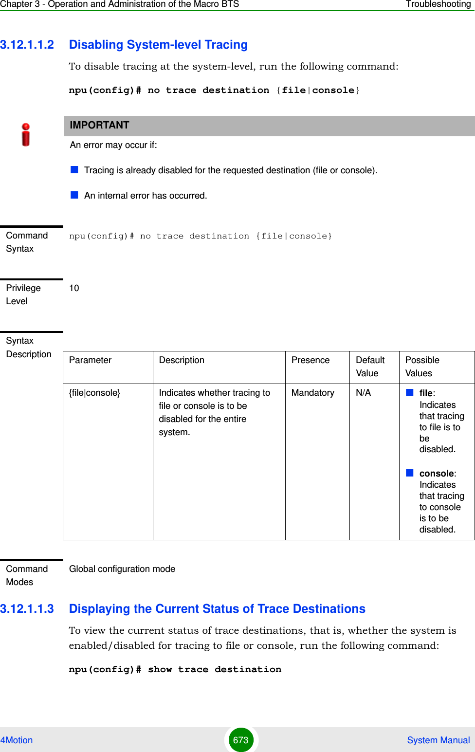
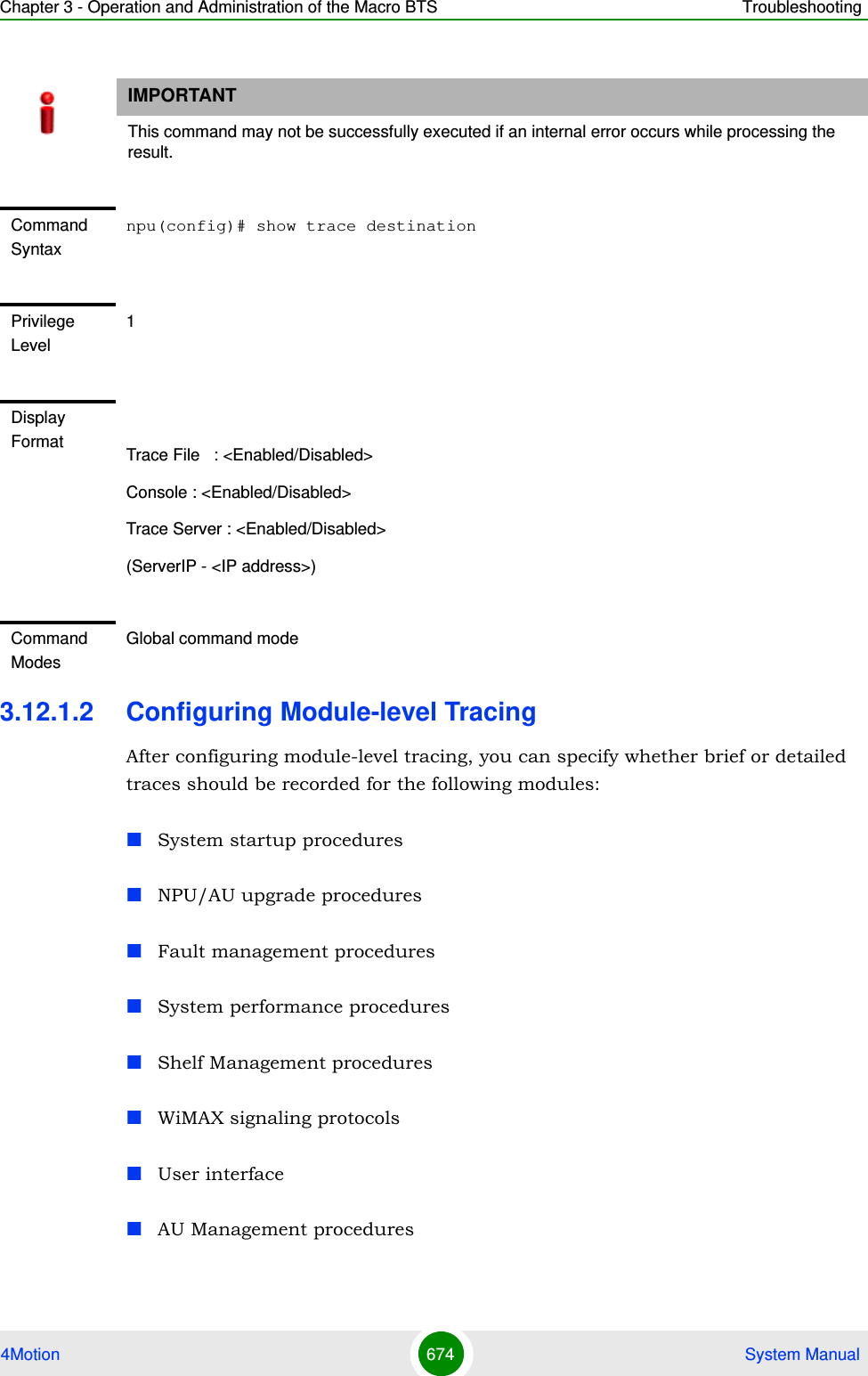
![Chapter 3 - Operation and Administration of the Macro BTS Troubleshooting4Motion 675 System ManualYou can also disable tracing for a particular module. This section describes the commands to be used for:“Configuring Trace Levels” on page 675“Disabling Module-level Tracing” on page 676“Displaying Trace Levels” on page 6773.12.1.2.1 Configuring Trace LevelsTo specify the trace level (brief or detailed) for each module, run the following command:npu(config)# trace level [{StartupMgr|SWDownload|FaultMgr|PerfMgr|ShelfMgr|SIGASN|UserIF|AUMgr}] {Brief|Detailed}The parameters in this command correspond to the system modules/procedures listed in the following table:Specify the module name if you want to configure the trace level separately for this module. If you do not specify the name of the module, the trace level that you configure in this command is applied to all modules. For example, run the following command if you want logs to be created for WiMAX signaling protocols when the trace level configured to Detailed:NOTEBy default, module-level tracing is disabled.Table 3-33: Modules for which Tracing can be EnabledParameter Refers to...StartupMgr System startup proceduresSWDownload Software upgrade proceduresFaultMgr Fault management proceduresShelfMgr Shelf management proceduresSIGASN WiMAX signaling protocolsUserIF User-initiated proceduresAUMgr Internal processes used for managing AUPerfMgr Performance management procedures](https://usermanual.wiki/Alvarion-Technologies/MICRO-25.Manual-p5/User-Guide-1329246-Page-128.png)
![Chapter 3 - Operation and Administration of the Macro BTS Troubleshooting4Motion 676 System Manualnpu(config)# trace level SIGASN Detailed3.12.1.2.2 Disabling Module-level TracingTo disable tracing for one or all modules, run the following command:npu(config)# no trace level [{StartupMgr|SWDownload|FaultMgr|PerfMgr|ShelfMgr|SIGASN|UserIF|AUMgr}]Specify the module if you want to disable tracing for that module. If you do not specify the name of the module, tracing is disabled for all modules.Command Syntaxnpu(config)# trace level [{StartupMgr|SWDownload|FaultMgr|PerfMgr|ShelfMgr|SIGASN|UserIF|AUMgr}] {Brief|Detailed}Privilege Level10Syntax Description Parameter Description Presence Default ValuePossible Values[{StartupMgr|SWDownload|FaultMgr|PerfMgr|ShelfMgr|SIGASN|UserIF|AUMgr}]Indicates the name of the module for which the trace level is to be configured. If you do not specify any value for this parameter, the same trace level is applied to all modules. For more information about these parameters, refer Table 3-33.Optional N/A StartupMgrSWDownloadFaultMgrPerfMgrShelfMgrSIGASNUserIFAUMgr{Brief|Detailed}Indicates the trace level to be applied for a particular or all modules. Mandatory N/A BriefDetailedCommand ModesGlobal configuration mode](https://usermanual.wiki/Alvarion-Technologies/MICRO-25.Manual-p5/User-Guide-1329246-Page-129.png)
![Chapter 3 - Operation and Administration of the Macro BTS Troubleshooting4Motion 677 System ManualFor example, run the following command if you want to disable tracing for WiMAX signaling protocols:npu(config)# no trace level SIGASN3.12.1.2.3 Displaying Trace LevelsTo view the trace levels configured for one or more modules, run the following command: npu(config)# show trace level [{StartupMgr|SWDownload|FaultMgr|PerfMgr|ShelfMgr|SIGASN|UserIF|AUMgr}]Command Syntaxnpu(config)# no trace level [{StartupMgr|SWDownload|FaultMgr|PerfMgr|ShelfMgr|SIGASN|UserIF|AUMgr}]Privilege Level10Syntax Description Parameter Description Presence Default ValuePossible Values[{StartupMgr|SWDownload|FaultMgr|PerfMgr|ShelfMgr|SIGASN|UserIF|AUMgr}]Indicates the name of the module for which tracing is to be disabled. If you do not specify any value for this parameter, tracing is disabled for all functionalities. For more information about these parameters, refer Table 3-33.Optional N/A StartupMgrSWDownloadFaultMgrPerfMgrShelfMgrSIGASNUserIFAUMgr\Command ModesGlobal configuration mode](https://usermanual.wiki/Alvarion-Technologies/MICRO-25.Manual-p5/User-Guide-1329246-Page-130.png)
![Chapter 3 - Operation and Administration of the Macro BTS Troubleshooting4Motion 678 System ManualSpecify the module for which you want to view the configured trace level. If you do not specify the name of the module, the trace levels configured for all modules is displayed.3.1 2 .2 Configuring Port MonitoringThe port monitoring feature enables you to mirror all incoming and outgoing traffic on an interface to another interface. You can configure one interface as the destination interface to which traffic from multiple interfaces can be mirrored. This section describes the commands to be executed for enabling/disabling port Command Syntaxnpu(config)# show trace level [{StartupMgr|SWDownload|FaultMgr|PerfMgr|ShelfMgr|SIGASN|UserIF|AUMgr}]Privilege Level1Syntax Description Parameter Description Presence Default ValuePossible Values[{StartupMgr|SWDownload|FaultMgr|PerfMgr|ShelfMgr|SIGASN|UserIF|AUMgr}]Indicates the name of the module for which you want to display the configured trace levels.If you do not specify any value for this parameter, the trace levels for all modules are displayed. For more information about these parameters, refer Table 3-33.Optional N/A StartupMgrSWDownloadFaultMgrPerfMgrShelfMgrSIGASNUserIFAUMgrDisplay FormatModule Name : Trace level<module name> : <Trace Level>Command ModesGlobal command mode](https://usermanual.wiki/Alvarion-Technologies/MICRO-25.Manual-p5/User-Guide-1329246-Page-131.png)
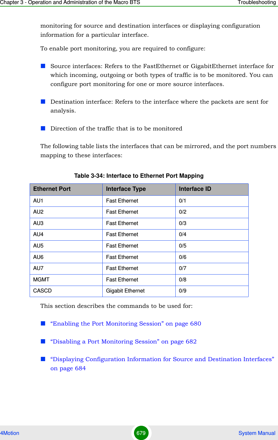
![Chapter 3 - Operation and Administration of the Macro BTS Troubleshooting4Motion 680 System Manual3.12.2.1 Enabling the Port Monitoring SessionThe port monitoring session refers to the association of a destination interface with one or more source interfaces. You can monitor incoming, outgoing or both types of traffic that is mirrored from the source interface to the destination interface.Run the following command to enable port monitoring for a source or destination interface:npu(config)# monitor session { source interface <interface-type> <interface-id> [{ rx | tx | both }] | destination interface <interface-type > <interface-id>}For example, to configure the Gigabit Ethernet 0/9 interface as the destination interface, you can run the following command:monitor session destination interface gigabitethernet 0/9You can now run the following commands to mirror incoming traffic for the source interfaces, Fast Ethernet 0/1 and Fast Ethernet 0/3:npu(config)# monitor session source interface fastethernet 0/1 rxnpu(config)# monitor session source interface fastethernet 0/3 rx All incoming and outgoing traffic for the 0/1 and 0/3 interfaces will be mirrored to the 0/9 interface.NOTEFor the current release, only one monitor session can be set up. This means that only one destination can be configured for one or more source interfaces.IMPORTANTAn error may occur if:The interface ID of the source or destination port you have specified is invalid. Refer Table 3-34 for the interface ID corresponding to each interface type.The port specified as the source interface is already specified as the destination interface for another port or vice versa.Command Syntaxnpu(config)# monitor session { source interface <interface-type> <interface-id> [{ rx | tx | both }] | destination interface <interface-type > <interface-id>}](https://usermanual.wiki/Alvarion-Technologies/MICRO-25.Manual-p5/User-Guide-1329246-Page-133.png)
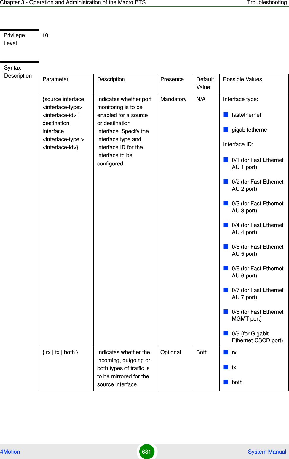
![Chapter 3 - Operation and Administration of the Macro BTS Troubleshooting4Motion 682 System Manual3.12.2.2 Disabling a Port Monitoring SessionYou can disable a port monitoring session for a source or destinations interface for which port monitoring is enabled. Run the following command to disable port monitoring for a source or destination interface:npu(config)# no monitor session [{source interface <interface-type> <interface-id> [{ rx | tx | both }]|destination interface <interface-type > < interface-id >}]Command ModesGlobal configuration modeIMPORTANTAn error may occur if:The interface ID of the source or destination port you have specified is invalid. Refer Table 3-34 for the interface ID corresponding to each interface type.Port monitoring is not enabled for the source or destination interface for which you are trying to disable port monitoring.Command Syntaxnpu(config)# no monitor session [{source interface <interface-type> <interface-id> [{ rx | tx | both }]|destination interface <interface-type > < interface-id >}]Privilege Level10](https://usermanual.wiki/Alvarion-Technologies/MICRO-25.Manual-p5/User-Guide-1329246-Page-135.png)
![Chapter 3 - Operation and Administration of the Macro BTS Troubleshooting4Motion 683 System ManualSyntax Description Parameter Description Presence Default ValuePossible Values[{source interface <interface-type> <interface-id> |destination interface <interface-type > < interface-id >}]Indicates whether port monitoring is to be disabled for a source or destination interface. Specify the interface type and interface ID for the interface to be configured.If source/destination interface types/id are not specified then all enabled port monitoring sessions will be disabled.Mandatory N/A Interface type:fastethernetgigabitetherneInterface ID:0/1 (for Fast Ethernet)0/2 (for Fast Ethernet)0/3 (for Fast Ethernet)0/4 (for Fast Ethernet)0/5 (for Fast Ethernet)0/6 (for Fast Ethernet)0/7 (for Fast Ethernet)0/8 (for Fast Ethernet)0/9 (for Gigabit Ethernet){ rx | tx | both } Indicates whether the incoming, outgoing or both types of traffic is to be disabled for mirroring for the source interface.Optional Both rxtxbothCommand ModesGlobal configuration mode](https://usermanual.wiki/Alvarion-Technologies/MICRO-25.Manual-p5/User-Guide-1329246-Page-136.png)