Alvarion Technologies MICRO-25 Microbase station transceiver User Manual 4Motion System Manual
Alvarion Technologies Ltd. Microbase station transceiver 4Motion System Manual
Contents
- 1. Manual p1
- 2. Manual p2
- 3. Manual p3
- 4. Manual p4
- 5. Manual p5
Manual p5

Chapter 3 - Operation and Administration of the Macro BTS Managing BSs
4Motion 548 System Manual
3.9.9.7.2 Displaying Configuration Information for Neighbor BS Required C/N
Level Parameters
To display configuration for the Neighbor BS Required C/N Level parameters, run
the following command:
npu# show nbr-requiredcnr bs [<(1 to 16777215 StepSize 1)> bs-id-lsb <(1 to
16777215 StepSize 1)>]
Specify the BS ID and the Neighbor BS ID (bs-id-lsb) if you want to display
configuration for a particular Neighbor BS in a particular BS. For example, to
display the Required C/N Level parameters of Neighbor BS 68000 in BS 66503,
run the following command:
npu# show nbr-requiredcnr bs 66053 bs-id-lsb 68000
Do not specify these parameters if you want to view configuration information for
all existing Neighbor BSs in all existing BSs. To display information for all
Neighbor BSs in all BSs, run the following command:
Display
Format
(for each
existing
Neighbor
BS in each
of the
existing BSs
if requested
for all)
BSIDLSB :<value>
NeighborBSIDLSB :<value>
SynchronizationIndicator :<value>
EIRP :<value>
Bandwidth(MHz) :<value>
UplinkFeedbackZonePermutationBase :<value>
PreambleIndex :<value>
UCDConfigurationChangeCount :<value>
DCDConfigurationChangeCount :<value>
IsotropicrecpwrforInitrang :<value>
CenterFrequency(MHz) :<value>
PagingGroupId :<value>
neighborStartRangeCodes :<value>
NeighborBsDlDataMIMOMode :<value>
Command
Modes
Global command mode

Chapter 3 - Operation and Administration of the Macro BTS Managing BSs
4Motion 549 System Manual
npu# show nbr-requiredcnr bs
Command
Syntax
npu# show nbr-requiredcnr bs [<(1 to 16777215 StepSize 1)> bs-id-lsb <(1 to 16777215
StepSize 1)> ]
Privilege
Level
1
Syntax
Description Parameter Description Presence Default
Value
Possible
Values
<(1 to 16777215
StepSize 1)>
The BS ID
Specify a value for this
parameter if you want to
display the Required C/N
Level parameters of a specific
Neighbor BS in a specific BS.
Do not specify a value for this
parameter if you want to
display the Required C/N
Level parameters of all
Neighbor BSs in all BSs.
Optional N/A 1-16777215
bs-id-lsb <(1 to
16777215
StepSize 1)>
The Neighbor BS ID.
Specify a value for this
parameter if you want to
display the Required C/N
Level parameters of a specific
Neighbor BS in a specific BS.
Do not specify a value for this
parameter if you want to
display the Required C/N
Level parameters of all
Neighbor BSs in all BSs.
Optional N/A 1-16777215

Chapter 3 - Operation and Administration of the Macro BTS Managing BSs
4Motion 550 System Manual
3.9.9.7.3 Displaying Configuration Information for Neighbor BS Triggers
Parameters
To display configuration information for Neighbor BS Triggers parameters, run the
following command:
npu# show nbr-triggers bs [<(1 to 16777215 StepSize 1)> bs-id-lsb <(1 to
16777215 StepSize 1)> TrigName {scnReqCinrMin | scnReqRssiMin |
scnReqRtdMax | scnRepCinrMaxNbs | scnRepRssiMaxNbs | scnRepCinrMargin
| scnRepRssiMargin | scnRepRtdMax | scnRepCinrMinSbs | scnRepRssiMinSbs
| hoReqCinrMaxNbs | hoReqRssiMaxNbs | hoReqCinrMargin | hoReqRssiMargin
| hoReqRtdMax | hoReqCinrMinSbs | hoReqRssiMinSbs}]
Specify the BS ID, Neighbor BS ID (bs-id-lsb) and Trigger name if you want to
display configuration for a particular Trigger. For example, to display the
scnReqCinrMin parameters of BS Neighbor 68000 in BS 66053, run the following
command:
npu# show nbr-triggers bs 66053 bs-id-lsb 68000 TrigName scnReqCinrMin
Display
Format
(for each
existing
Neighbor
BS in each
of the
existing BSs
if requested
for all)
BSIDLSB :<value>
NeighborBSIDLSB :<value>
RequiredCNRforACK :<value>
RequiredCNRforCQI :<value>
RequiredCNRforCDMA :<value>
RequiredCNRforQPSK1/2 :<value>
RequiredCNRforQPSK3/4 :<value>
RequiredCNRfor16QAM1/2 :<value>
RequiredCNRfor16QAM3/4 :<value>
RequiredCNRfor64QAM1/2 :<value>
RequiredCNRfor64QAM2/3 :<value>
RequiredCNRfor64QAM3/4 :<value>
RequiredCNRfor64QAM5/6 :<value>
Command
Modes
Global command mode

Chapter 3 - Operation and Administration of the Macro BTS Managing BSs
4Motion 551 System Manual
Do not specify these parameters if you want to view configuration information for
all existing Neighbor BSs in all BSs. To display information for all Neighbor BSs in
all BSs, run the following command:
npu# show nbr-triggers bs
Command
Syntax
npu# show nbr-triggers bs [<(1 to 16777215 StepSize 1)> bs-id-lsb <(1 to 16777215
StepSize 1)> TrigName {scnReqCinrMin | scnReqRssiMin | scnReqRtdMax | hoReqCinrMaxNbs |
hoReqRssiMaxNbs | hoReqCinrMargin | hoReqRssiMargin | hoReqRtdMax | hoReqCinrMinSbs |
hoReqRssiMinSbs} ]
Privilege
Level
1
Syntax
Description Parameter Description Presence Default
Value
Possible Values
<(1 to 16777215
StepSize 1)>
The BS ID
Specify a value for
this parameter if you
want to display a
specific Trigger in a
specific Neighbor BS
of a specific BS. Do
not specify a value for
this parameter if you
want to display the
Triggers of all
Neighbor BSs in all
BSs.
Optional N/A 1-16777215
bs-id-lsb <(1 to
16777215 StepSize
1)>
The Neighbor BS ID.
Specify a value for
this parameter if you
want to display a
specific Trigger in a
specific Neighbor BS
of a specific BS. Do
not specify a value for
this parameter if you
want to display the
Triggers of all
Neighbor BSs in all
BSs.
Optional N/A 1-16777215

Chapter 3 - Operation and Administration of the Macro BTS Managing BSs
4Motion 552 System Manual
3.9.9.7.4 Displaying Configuration Information for Neighbor BS Specific BS
Triggers Parameters
To display configuration information for Neighbor BS Specific BS Triggers
parameters, run the following command:
npu# show nbr-specific bs [<(1 to 16777215 StepSize 1)> bs-id-lsb <(1 to
16777215 StepSize 1)> TrigName {hoReqCinrMaxNbs | hoReqRssiMaxNbs |
hoReqCinrMargin | hoReqRssiMargin} ]
Specify the BS ID, Neighbor BS ID (bs-id-lsb) and Specific BS Trigger name if you
want to display configuration for a particular Trigger. For example, to display the
hoReqRssiMaxNbs parameters of BS Neighbor 68000 in BS 66053, run the
following command:
npu# show nbr-specific bs 66053 bs-id-lsb 68000 TrigName
hoReqRssiMaxNbs
TrigName
{scnReqCinrMin |
scnReqRssiMin |
scnReqRtdMax |
hoReqCinrMaxNbs |
hoReqRssiMaxNbs |
hoReqCinrMargin |
hoReqRssiMargin |
hoReqRtdMax |
hoReqCinrMinSbs |
hoReqRssiMinSbs} ]
The Trigger name
Specify only if you
want to display a
specific Trigger of a
specific Neighbor BS
in a specific BS. Do
not specify if you
want to display all
Triggers parameters
of all Neighbor BSs in
all BSs
scnReqCinrMin
scnReqRssiMin
scnReqRtdMax
hoReqCinrMaxNbs
hoReqRssiMaxNbs
hoReqCinrMargin
hoReqRssiMargin
hoReqRtdMax
hoReqCinrMinSbs
hoReqRssiMinSbs}
Display
Format
(for a
selected
Trigger)
BSIDLSB :<value>
BSIDLSB :value>
scnReqCinrMin :value>
Command
Modes
Global command mode

Chapter 3 - Operation and Administration of the Macro BTS Managing BSs
4Motion 553 System Manual
Do not specify these parameters if you want to view configuration information for
all existing Neighbor BSs in all BSs. To display information for all Neighbor BSs in
all BSs, run the following command:
npu# show nbr-triggers bs
Command
Syntax
npu# show nbr-specific bs [<(1 to 16777215 StepSize 1)> bs-id-lsb <(1 to 16777215
StepSize 1)> TrigName {hoReqCinrMaxNbs | hoReqRssiMaxNbs | hoReqCinrMargin |
hoReqRssiMargin} ]
Privilege
Level
1
Syntax
Description Parameter Description Presence Default
Value
Possible Values
<(1 to 16777215
StepSize 1)>
The BS ID
Specify a value for
this parameter if you
want to display a
specific Specific BS
Trigger in a specific
Neighbor BS of a
specific BS. Do not
specify a value for
this parameter if you
want to display the
Specific BS Triggers
of all Neighbor BSs in
all BSs.
Optional N/A 1-16777215

Chapter 3 - Operation and Administration of the Macro BTS Managing BSs
4Motion 554 System Manual
3.9.9.7.5 Displaying Configuration Information for All Neighbor BS Parameters
To display configuration for the all Neighbor BS parameters, run the following
command:
npu# show nbr-all bs [<(1 to 16777215 StepSize 1)> bs-id-lsb <(1 to 16777215
StepSize 1)>]
bs-id-lsb <(1 to
16777215 StepSize
1)>
The Neighbor BS ID.
Specify a value for
this parameter if you
want to display a
specific Specific BS
Trigger in a specific
Neighbor BS of a
specific BS. Do not
specify a value for
this parameter if you
want to display the
Specific BS Triggers
of all Neighbor BSs
in all BSs.
Optional N/A 1-16777215
TrigName
{hoReqCinrMaxNbs |
hoReqRssiMaxNbs |
hoReqCinrMargin |
hoReqRssiMargin} ]
The Trigger name
Specify only if you
want to display a
specific Specific BS
Trigger of a specific
Neighbor BS in a
specific BS. Do not
specify if you want to
display all Specific BS
Triggers parameters
of all Neighbor BSs in
all BSs
{hoReqCinrMaxNbs
hoReqRssiMaxNbs
hoReqCinrMargin
hoReqRssiMargin}
Display
Format
(for a
selected
Trigger)
BSIDLSB :<value>
BSIDLSB :value>
hoReqRssiMaxNbs :value>
Command
Modes
Global command mode

Chapter 3 - Operation and Administration of the Macro BTS Managing BSs
4Motion 555 System Manual
Specify the BS ID and the Neighbor BS ID (bs-id-lsb) if you want to display
configuration for a particular Neighbor BS in a particular BS. For example, to
display all parameters of Neighbor BS 68000 in BS 66503, run the following
command:
npu# show nbr-all bs 66053 bs-id-lsb 68000
Do not specify these parameters if you want to view configuration information for
all existing Neighbor BSs in all existing BSs. To display information for all
Neighbor BSs in all BSs, run the following command:
npu# show nbr-all bs
Command
Syntax
npu# show nbr-all bs [<(1 to 16777215 StepSize 1)> bs-id-lsb <(1 to 16777215 StepSize 1)> ]
Privilege
Level
10
Syntax
Description Parameter Description Presence Default
Value
Possible
Values
<(1 to 16777215
StepSize 1)>
The BS ID
Specify a value for this
parameter if you want to
display the parameters of a
specific Neighbor BS in a
specific BS. Do not specify a
value for this parameter if you
want to display the
parameters of all Neighbor
BSs in all BSs.
Optional N/A 1-16777215
bs-id-lsb <(1 to
16777215
StepSize 1)>
The Neighbor BS ID.
Specify a value for this
parameter if you want to
display the parameters of a
specific Neighbor BS in a
specific BS. Do not specify a
value for this parameter if you
want to display the
parameters of all Neighbor
BSs in all BSs.
Optional N/A 1-16777215

Chapter 3 - Operation and Administration of the Macro BTS Managing BSs
4Motion 556 System Manual
3.9 .10 Managing the RF Frequency Para m e t e r
After enabling the BS configuration mode, you can configure the RF frequency
parameter (refer to Section 3.9.10.1).
You can display configuration information for the RF frequency parameter of a
selected or all existing BSs (refer to Section 3.9.10.2).
3.9.10.1 Configuring the RF Frequency Parameter
From the BS configuration mode, run the following command:
npu(config-bs-66053)# rf [frequency <(2022.5 to 2217.5 StepSize 0.125) |
(2302.5 to 2397.5 StepSize 0.125) | (2487.5 to 2687.5 StepSize 0.125) | (3302.5
to 3397.5 StepSize 0.125) | (3402.5 to 3597.5 StepSize 0.125) | (3602.5 to 3797.5
StepSize 0.125)>]
Command
Modes
Global command mode
To configure the RF frequency parameter:
Command
Syntax
npu(config-bs-66053)# rf [frequency <((2022.5 to 2217.5 StepSize
0.125) | (2302.5 to 2397.5 StepSize 0.125) | (2487.5 to 2687.5
StepSize 0.125) | (3302.5 to 3397.5 StepSize 0.125) | (3402.5 to
3597.5 StepSize 0.125) | (3602.5 to 3797.5 StepSize 0.125)>]
Privilege
Level
10
Syntax
Description Parameter Description Presence Default
Value
Possible
Values

Chapter 3 - Operation and Administration of the Macro BTS Managing BSs
4Motion 557 System Manual
3.9.10.2 Displaying Configuration Information for the RF Frequency
Parameter
To display configuration information of the RF frequency parameter, run the
following command:
npu# show rf bs [<(1 to 16777215 StepSize 1)
Specify the BS ID if you want to display information for a particular BS. For
example, to display the RF frequency of BS 66053, run the following command:
npu# show rf bs 66053
Do not specify this parameter if you want to view information for all existing BSs.
To display information for all BSs, run the following command:
npu# show rf bs
[frequency
<(2022.5 to
2217.5 StepSize
0.125) | (2302.5 to
2397.5 StepSize
0.125) | (2487.5 to
2687.5 StepSize
0.125) | (3302.5 to
3397.5 StepSize
0.125) | (3402.5 to
3597.5 StepSize
0.125) | (3602.5 to
3797.5 StepSize
0.125)>]
The center of the frequency
band in which the BS will
transmit, in MHz.
Must be within the valid range
of the relevant ODU.
The indicated Possible Values
are for a bandwidth of fiveMhz.
For a different bandwidth, the
actually valid values are from
f1+1/2BW to f2-1/2BW, where
f1 is the lowest frequency of
the ODU’s radio band. Note
that
oDU23052360000N361by1Y0
(16) includes two bands:
2305-2320, 2345-2360 MHz.),
f2 is the highest frequency of
the ODU’s band, and BW is
the configured bandwidth (see
“Configuring the
Baseband Bandwidth
Parameter” on page 559).
Mandatory N/A 2022.5 to
2217.5 in
steps of 0.125
2302.5 to
2397.5 in
steps of 0.125
2487.5 to
2687.5 in
steps of 0.125
3302.5 to
3397.5 in
steps of 0.125
3402.5 to
3597.5 in
steps of 0.125
3602.5 to
3797.5 in
steps of 0.125
Command
Modes
bs configuration mode
IMPORTANT
When creating a new BS, the mandatory frequency parameter must be configured.

Chapter 3 - Operation and Administration of the Macro BTS Managing BSs
4Motion 558 System Manual
3.9 .11 Managing the Baseband Ba ndw idth
Pa ra m e t e r
After enabling the BS configuration mode, you can configure the Baseband
bandwidth parameter (refer to Section 3.9.11.1).
You can display configuration information for the Baseband bandwidth parameter
of a selected or all existing BSs (refer to Section 3.9.11.2).
Command
Syntax
npu# show rf bs [<(1 to 16777215 StepSize 1)
Privilege
Level
1
Syntax
Description Parameter Description Presence Default
Value
Possible
Values
<(1 to 16777215
StepSize 1)>
The BS ID
Specify a value for this
parameter if you want to
display the RF frequency
parameter of a specific BS.
Do not specify a value for this
parameter if you want to
display the RF frequency
parameter of all BSs.
Optional N/A 1-16777215
Display
Format
(for each
existing BS
if requested
for all BSs)
BSIDLSB :<value>
Frequency :<value>
Command
Modes
Global command mode

Chapter 3 - Operation and Administration of the Macro BTS Managing BSs
4Motion 559 System Manual
3.9.11.1 Configuring the Baseband Bandwidth Parameter
From the BS configuration mode, run the following command:
npu(config-bs-66053)# baseband [bandwidth {fiveMHz | tenMHz | sevenMHz}]
Note that the valid value ranges (and in some cases also default value) of certain
parameters are affected by the value configured for the bandwidth parameter. If
you change the bandwidth, verify that these parameters are configured properly:
To configure the Baseband bandwidth parameter:
IMPORTANT
A bandwidth of 7 MHz (sevenMHz) is not applicable for ODUs in the 2.x GHz band.
Command
Syntax
npu(config-bs-66053)# baseband [bandwidth {fiveMHz | tenMHz |
sevenMHz} ]
Privilege
Level
10
Syntax
Description Parameter Description Presence Default
Value
Possible
Values
[bandwidth {fiveMHz |
tenMHz | sevenMHz} ]
BS channel
bandwidth
Mandatory N/A fiveMHz
tenMHz
sevenMHz
Command
Modes
bs configuration mode
IMPORTANT
When creating a new BS, the mandatory frequency parameter must be configured.
Table Parameters
RF (see Section 3.9.10.1) frequency

Chapter 3 - Operation and Administration of the Macro BTS Managing BSs
4Motion 560 System Manual
3.9.11.2 Displaying Configuration Information for the Baseband
Bandwidth Parameter
To display configuration information of the Baseband bandwidth parameter, run
the following command:
npu# show baseband bs [<(1 to 16777215 StepSize 1)
Specify the BS ID if you want to display information for a particular BS. For
example, to display the Baseband bandwidth of BS 66053, run the following
command:
npu# show baseband bs 66053
Do not specify this parameter if you want to view information for all existing BSs.
To display information for all BSs, run the following command:
npu# show baseband bs
Airframe Structure, General (see
Section 3.9.12.2.1)
ul-dl-allocation
Airframe Structure, Map Zone (see
Section 3.9.12.2.2)
majorgrps
Airframe Structure, Uplink Data Zone (see
Section 3.9.12.2.6)
subchannels
Triggers (see Section 3.9.7.1) triggers-scnreq-rtd-max
triggers-horeq-rtd-max
Command
Syntax
npu# show baseband bs [<(1 to 16777215 StepSize 1)
Privilege
Level
1

Chapter 3 - Operation and Administration of the Macro BTS Managing BSs
4Motion 561 System Manual
3.9 .12 Managing Airframe Structure Pa ra meters
1Enable the Airframe configuration mode (refer to Section 3.9.12.1)
2You can now execute any of the following tasks:
»Configure one or more of the Airframe parameters tables (refer to
Section 3.9.12.2)
»Restore the default values of parameters in one or more of the Airframe
parameters tables (refer to Section 3.9.12.3)
» Terminate the Airframe configuration mode (refer to Section 3.9.12.4)
Syntax
Description Parameter Description Presence Default
Value
Possible
Values
<(1 to 16777215
StepSize 1)>
The BS ID
Specify a value for this
parameter if you want to
display the Baseband
bandwidth parameter of a
specific BS. Do not specify a
value for this parameter if you
want to display the Baseband
bandwidth parameter of all
BSs.
Optional N/A 1-16777215
Display
Format
(for each
existing BS
if requested
for all BSs)
BSIDLSB :<value>
Bandwidth :<value>
Command
Modes
Global command mode
To configure Airframe Structure parameters:

Chapter 3 - Operation and Administration of the Macro BTS Managing BSs
4Motion 562 System Manual
In addition, you can, at any time, display configuration information for each of the
Airframe parameters tables (refer to Section 3.9.12.5).
3.9.12.1 Enabling the Airframe Configuration Mode
To configure the Airframe parameters, first enable the Airframe configuration
mode. Run the following command to enable the Airframe configuration mode.
npu(config-bs-66053)# airframe
After enabling the Airframe configuration mode, you can execute any of the
following tasks:
Configure one or more of the Airframe parameters tables (refer to
Section 3.9.12.2)
Restore the default values of parameters in one or more of the Airframe
parameters tables (refer to Section 3.9.12.3)
After executing the above tasks, you can terminate the Airframe configuration
mode (refer to Section 3.9.12.4) and return to the BS configuration mode.
Note that for properly completing the Airframe configuration the apply command
must be executed prior to exiting the Airframe configuration mode.
3.9.12.2 Configuring Airframe Parameters
After enabling the Airframe configuration mode you can configure the following
parameters tables:
General (refer to Section 3.9.12.2.1)
Map Zone (refer to Section 3.9.12.2.2)
Command
Syntax
npu(config-bs-66053)# airframe
Privilege
Level
10
Command
Modes
bs configuration mode

Chapter 3 - Operation and Administration of the Macro BTS Managing BSs
4Motion 563 System Manual
Downlink Diversity (refer to Section 3.9.12.2.3)
Uplink Feedback Zone (refer to Section 3.9.12.2.4)
Downlink Data Zone (refer to Section 3.9.12.2.5)
Uplink Data Zone (refer to Section 3.9.12.2.6)
Mimo (refer to Section 3.9.12.2.7)
3.9.12.2.1 Configuring Airframe General Parameters
To configure the Airframe General parameters, run the following command:
npu(config-bs-66053-airframe)# general [cell-id <(0 to 31 StepSize 1)>]
[preamble-grp <(1 to 2 StepSize 1)>] [segment <(0 to 2 StepSize 1)>] [frame-offset
<zero|random>] [ul-duration <(3 to 7 StepSize 1 | 10 to 10 StepSize1)>]
[nbr-beam-forming {yes | no} ]
Neighbor BS Beam Forming (nbr-beam-forming): Applicable only for unit
operating in MIMO Matrix A or B mode. The beam forming mechanism is based on
symmetry in performance between uplink and down link. To compensate for
possible differences due to HW of the ODU, a special low-level calibration signal is
transmitted periodically in each link. During the time this calibration signal is
transmitted all other radio links of the same BS and all its neighbors should not
transmit, to reduce potential interference. The Beam Forming mechanism ensures
that all neighboring BSs operating in Beam Forming mode will enter into silent
mode when necessary. A unit operating in Matrix A or B mode should enter into
silent mode when necessary (based on frame number information) only if it has
neigboring BSs operating in Beam Forming mode.
IMPORTANT
After completing the Airframe configuration, do not forget to execute the apply command before
exiting the Airframe configuration mode:
npu(config-bs-66053-airframe)# apply
IMPORTANT
When creating a new BS, all mandatory Neighbor BS General parameters must be configured.

Chapter 3 - Operation and Administration of the Macro BTS Managing BSs
4Motion 564 System Manual
Command
Syntax
npu(config-bs-66053-airframe)# general [cell-id <(0 to 31 StepSize
1)> ] [preamble-grp <(1 to 2 StepSize 1)>] [segment <(0 to 2
StepSize 1)> ] [frame-offset <zero|random)> ] [ul-duration <(3 to
7 StepSize 1 | 10 to 10 StepSize1)> ] [nbr-beam-forming {yes | no}
]
Privilege
Level
10
Syntax
Description Parameter Description Presence Default
Value
Possible Values
[cell-id <(0 to 31
StepSize 1)> ]
The Cell ID (IDCell) used
for preamble selection.
Mandatory
when
creating a
new BS.
N/A 0 - 31
[preamble-grp <(1
to 2 StepSize 1)>]
The preamble group. A
value of 2 is available only
for the following
combinations of segment
and cell-id values:
segment=0, cell-id=0, 3, 6,
9, 12, 15.
segment=1, cell-id=1, 4, 7,
10, 13, 16.
segment=2, cell-id=2, 5, 8,
11, 14, 17.
Optional 1 1 - 2
[segment <(0 to 2
StepSize 1)> ]
The segment (BS) number
in a three sector BS (0-2).
This number influences
the preamble selection
and the major group used
for the FDC transmission.
Mandatory
when
creating a
new BS.
N/A 0 - 2
[frame-offset
<zero|random> ]
Controls the offset applied
between the internal frame
count and the reported
frame number.
If random is selected, the
AU will choose a random
number between 0 to 15.
Mandatory
when
creating a
new BS.
zero zero (0)
random

Chapter 3 - Operation and Administration of the Macro BTS Managing BSs
4Motion 565 System Manual
3.9.12.2.2 Configuring Airframe Map Zone Parameters
To configure the Airframe Map Zone parameters, run the following command:
npu(config-bs-66053-airframe)# mapzone [size <(-1 to -1 StepSize 1) | (2 to 16
StepSize 2)>] [majorgrps <hex-string>] [repetition <(1 to 1 StepSize 1) | (2 to 6
StepSize 2)>] [RCID-Usage {enable | disable} ]
Each transmitted MAP includes allocations for each MS it served, using the MS’s
CID for identifying each MS. The original CID includes 16 bits, which is
significantly more than practically needed since a maximum of 500 MSs can be
served by each BS. To reduce overhead, a smaller number of bits can be used,
based on RCID (Reduced CID) defined in the standard. This mechanism can be
used only if all MSs served by the BS support RCID. When enabled, CIDs of either
7 or 11 bits will be dynamically used, according to the current number of MS
served at each given moment.
[ul-duration <(3 to 7
StepSize 1 | 10 to
10 StepSize1)> ]
The total duration of the
uplink in a frame, in slots.
(one slot equals 3
symbols).
The range is 4-7 or 10 for
bandwidth = 5 or 10MHz,
3-5 or 7 for bandwidth =
7MHz. To avoid BS-BS
interference, the
ul-duration must be
identical in all BSs in a
geographical region.
Mandatory
when
creating a
new BS.
N/A 3 - 7, 10
[nbr-beam-forming
{yes | no} ]
Applicable only for BSs
using MIMO MatrixAorB
mode. Indicates whether
any of the neighboring
BSs operates in
beamForming mode.
Optional no yes
no
Command
Modes
bs airframe configuration mode
IMPORTANT
When creating a new BS, the mandatory Airframe Map Zone majorgrps parameter must be
configured.

Chapter 3 - Operation and Administration of the Macro BTS Managing BSs
4Motion 566 System Manual
Command
Syntax
npu(config-bs-66053-airframe)# mapzone [size <(-1 to -1 StepSize 1)
| (2 to 16 StepSize 2)> ] [majorgrps <hex-string>] [repetition <(1
to 1 StepSize 1) | (2 to 6 StepSize 2)> ] [RCID-Usage {enable |
disable} ]
Privilege
Level
10
Syntax
Description Parameter Description Presence Default
Value
Possible
Values
size <(-1 to -1
StepSize 1) | (2 to
16 StepSize 2)>
The map zone size in
symbols. A value of "-1"
means the map zone size
will be dynamic.
Optional 6 -1, 2, 4, 6, 8, 10,
12, 14, 16.

Chapter 3 - Operation and Administration of the Macro BTS Managing BSs
4Motion 567 System Manual
majorgrps
<hex-string>
The Major groups allocated
to the BS for maps
transmission.
Two hexadecimal numbers
representing 8 bits
numbered 0 to 7 (left to
right). Bits 0 to 5 indicate
whether Subchannel
Groups 0 to 5 (respectively)
are allocated. Bit 6 and 7
are set to 0.
If BW=5 MHz, bits 1, 3 and
5 are not relevant ("don't
care"). The value must be
set to A8.
For BW=7/10 MHz with
Reuse 1, bits 0 to 5 must be
set. The value must be set
to fc.
For BW=7/10 MHz with
Reuse 3: If segment (see
Section 3.9.12.2.1) = 0,
then bits #0 and 1 should
be set. The value must be
set to c0.
If segment = 1, then bits #2
and 3 should be set. The
value must be set to 30.
If segment = 2, then bits #4
and 5 should be set. The
value must be set to 0c.
Mandatory
when
creating a
new BS.
N/A a string of two
hexadecimal
numbers.
repetition <(1 to 1
StepSize 1) | (2 to 6
StepSize 2)>
The basic repetition used in
the transmission of the
maps using QPSK 1/2 (1
means no repetitions).
Optional 6 1, 2, 4, 6
RCID-Usage
{enable | disable}
Indicates whether RCID
should be used,
Optional disable enable
disable
Command
Modes
bs airframe configuration mode

Chapter 3 - Operation and Administration of the Macro BTS Managing BSs
4Motion 568 System Manual
3.9.12.2.3 Configuring the Airframe Downlink Diversity Mode Parameter
The system supports the following operation modes in the downlink:
MIMO Matrix A or B
Beam Forming
In MIMO Matrix A or B mode the system can use either MIMO Matrix A or Matrix
B. The selection between Matrix A and Matrix B is performed automatically for
each MS according to link conditions and supported MS capabilities.
MIMO Matrix A for Coverage Gain: In configuration with multiple transmit/receive
antennas, a single data stream is transmitted in parallel over multiple paths. A
mathematical algorithm known as Space Time Codes (STC) is used to encode the
data streams to make them orthogonal to each other. This improves the signal to
noise ratio at the receiver side, resulting in increased range and better throughput
for subscribers that are difficult to reach (e.g. deep indoors).
MIMO Matrix B for Increased Capacity: This flavor of MIMO, also known as
Spatial Multiplexing MIMO (SM-MIMO), sends an independent data stream over
each antenna. Thus, in case signal conditions are good, the data rate is increased
and in excellent conditions may be doubled.
Beam Forming mode is applicable only for 4x4 configurations (4-channels AU, 2x2
or 4x2 ODUs that support beam forming). The system learns the signals received
from each MS in each of the antennas, and adapt the transmitted signals
accordingly by sending the same data into radio signals at specific relative phases,
Beamforming creates a narrower antenna beam than that generated by a baseline
fixed-beam antenna, with the beam acting as a powerful adaptive directional
antenna. The signal with its transmitted energy is electronically formed and
directed to a particular subscriber, resulting in higher downlink gain for data,
greater downlink throughput and lower interference.
To configure the Airframe Downlink Diversity mode parameter, run the following
command:
npu(config-bs-66053-airframe)# dldiversity [mode < matrixAorB |
beamForming>]
IMPORTANT
When creating a new BS, the Airframe Downlink Diversity mode parameter must be configured
(even if configured to the default value).

Chapter 3 - Operation and Administration of the Macro BTS Managing BSs
4Motion 569 System Manual
3.9.12.2.4 Configuring Airframe Uplink Feedback Zone Parameter
To configure the Airframe Uplink Feedback Zone parameter, run the following
command:
npu(config-bs-66053-airframe)# ulfeedbackzone permbase <(0 to 69 StepSize
1)>
Command
Syntax
npu(config-bs-66053-airframe)# dldiveraity [mode <matrixAorB |
beamForming>]
Privilege
Level
10
Syntax
Description Parameter Description Presence Default
Value
Possible
Values
mode
<matrixAorB
|beamForming>
The diversity mode used in
downlink transmissions.
beamForming is not
applicable for 2-channels
AU.
Optional matrixA0rB matrixAorB
beamForming
Command
Modes
bs airframe configuration mode
IMPORTANT
When creating a new BS, the Airframe Structure Uplink Feedback Zone mandatory permbase
parameter must be configured.
Command
Syntax
npu(config-bs-66053-airframe)# ulfeedbackzone permbase <(0 to 69
StepSize 1)>
Privilege
Level
10

Chapter 3 - Operation and Administration of the Macro BTS Managing BSs
4Motion 570 System Manual
3.9.12.2.5 Configuring Airframe Downlink Data Zone Parameter
To configure the Airframe Downlink Data Zone parameter, run the following
command:
npu(config-bs-66053-airframe)# dldatazone permbase <(0 to 31 StepSize 1)>
Syntax
Description Parameter Description Presence Default
Value
Possible
Values
[permbase <(0 to 69
StepSize 1)> ]
The permutation base used
in the feedback zone
Mandatory
when
creating a
new BS.
N/A 0 - 69
Command
Modes
bs airframe configuration mode
IMPORTANT
When creating a new BS, the Airframe Uplink Feedback Zone mandatory permbase parameter
must be configured.
Command
Syntax
npu(config-bs-66053-airframe)# dldatazone permbase <(0 to 31 StepSize
1)>
Privilege
Level
10
Syntax
Description Parameter Description Presence Default
Value
Possible
Values
[permbase <(0 to 31
StepSize 1)> ]
The permutation base used
in the downlink data zone
Mandatory
when
creating a
new BS.
N/A 0 - 31
Command
Modes
bs airframe configuration mode

Chapter 3 - Operation and Administration of the Macro BTS Managing BSs
4Motion 571 System Manual
3.9.12.2.6 Configuring Airframe Uplink Data Zone Parameter
To configure the Airframe Uplink Data Zone parameter, run the following
command:
npu(config-bs-66053-airframe)# uldatazone permbase <(0 to 69 StepSize 1)>
3.9.12.2.7 Configuring Airframe MIMO Parameters
The DL MIMO feature provides a TX diversity gain or, when physical conditions
allow, data rate gain (double rate).
The gain is allowed thanks to two or four transmitting antennas at the BS side,
two receiving antennas at the MS side, and encoding/decoding capabilities of both
MS and BS.
TX diversity gain is achieved when MS works at matrix A/STC, space time coding,
AKA STTD (vertical encoding) mode.
IMPORTANT
When creating a new BS, the Airframe Structure Uplink Data Zone mandatory permbase parameter
must be configured.
Command
Syntax
npu(config-bs-66053-airframe)# uldatazone permbase <(0 to 69 StepSize
1)>
Privilege
Level
10
Syntax
Description Parameter Description Presence Default
Value
Possible
Values
[permbase <(0 to 69
StepSize 1)> ]
The permutation base
used in the uplink
datazone
Mandatory
when
creating a
new BS
0 to 69 in steps
of 1
Command
Modes
bs airframe configuration mode

Chapter 3 - Operation and Administration of the Macro BTS Managing BSs
4Motion 572 System Manual
Data rate gain is achieved when MS works at matrix B/SM, spatial multiplexing
MIMO mode.
It is assumed that either all MSs support MIMO (not necessary both modes) or all
MSs don't support MIMO (SIMO support only).
The DL MIMO feature influences several system elements such as frame
structure, rate adaptation and feedback zone.
To configure the Airframe MIMO parameters, run the following command:
npu(config-bs-66053-airframe)# mimo [first-zone-min-size <(-1 to -1 StepSize 1)
| (2 to 34 StepSize 2)> ] [first-zone-max-size <(-1 to -1 StepSize 1) | (2 to 34
StepSize 2)> ] [max-map-size <(-1 to -1 StepSize 1) | (10 to 300 StepSize 10)> ]
Command
Syntax
npu(config-bs-66053-airframe)# mimo [first-zone-min-size <(-1 to -1
StepSize 1) | (2 to 34 StepSize 2)> ] [first-zone-max-size <(-1 to
-1 StepSize 1) | (2 to 34 StepSize 2)> ] [max-map-size <(-1 to -1
StepSize 1) | (10 to 300 StepSize 10)> ]
Privilege
Level
10
Syntax
Description Parameter Description Presence Default
Value
Possible
Values

Chapter 3 - Operation and Administration of the Macro BTS Managing BSs
4Motion 573 System Manual
Recommended values for First Zone Minimum Size and Maximum Size:
[first-zone-mi
n-size <(-1 to
-1 StepSize 1)
| (2 to 34
StepSize 2)> ]
Determines the initial size
(in OFDMA symbols) of the
first zone. When reuse 3 is
used within first zone, this
parameter should be equal
across all BSs within
deployment.
See recommended values
in Table 3-31 below. Other
values should be avoided.
In the current release this is
the actual size of the first
zone.
For reuse 1 the default (no
limitation) can be used-the
actual size will be set
dynamically according to
the configuration. For reuse
3 a specific value must be
configured.
Optional -1 (no
limitation)
-1 (no
limitation) or
2xN where N=1
to 17.
[first-zone-ma
x-size <(-1 to
-1 StepSize 1)
| (2 to 34
StepSize 2)> ]
Maximum size (in OFDMA
symbols) for first zone.
Used mainly for
performance control
capability within frame.
Cannot be lower than
first-zone-min-size.
In the current release the
value of this parameter is
ignored First Zone size is
defined only by
first-zone-min-size.
Optional -1 (no
limitation)
-1 (no
limitation) or
2xN where N=1
to 17.
[max-map-size <(-1
to -1 StepSize 1) |
(10 to 300 StepSize
10)> ]
Limits the maximum size of
maps (in slots)
Optional -1 (no
limitation)
-1 (no
limitation) or 10
to 300 in steps
of 10.
Command
Modes
bs airframe configuration mode

Chapter 3 - Operation and Administration of the Macro BTS Managing BSs
4Motion 574 System Manual
* First Zone Scheme is being determined by the selected Map Major Groups:
For 7/10 MHz Full Loading means all Major Groups (0-5) are selected.
For 5MHz Full Loading means that all relevant Major Groups (0, 2, 4) are
selected.
For First Zone Maximum Size the values are:
If First Zone Minimum Size is set to No Limitations, the value range for
Maximum Size is the same as for Minimum Size.
Else, the value range is No Limitations or First Zone Minimum Size+2N, up to
a maximum of Y as defined below.
Table 3-31: First Zone Minimum Size Recommended Value Range
Bandwidth
(MHz)
First Zone
Scheme*
Basic Map Repetition Minimum Size (symbols) (up to a
maximum of Y as defined below)
7/10 Full Loading 6 No Limitation or 8+2N
4 No Limitation or 6+2N
2 No Limitation or 4+2N
1 No Limitation or 4+2N
Reuse 1/3 6 N/A (non trivial configuration)
48+2N
26+2N
16+2N
5 MHz Full Loading 6 N/A (non trivial configuration)
4 No Limitation or 8+2N
2 No Limitation or 6+2N
1 No Limitation or 4+2N
Reuse 1/3 6 N/A (non trivial configuration)
4 N/A (non trivial configuration)
2 N/A (non trivial configuration)
1 N/A (non trivial configuration)

Chapter 3 - Operation and Administration of the Macro BTS Managing BSs
4Motion 575 System Manual
The value of Y that sets the upper limit for the Minimum and Maximum Size
parameters depends on the Maximum Cell Radius and Total Uplink Duration
parameters, using the following formula:
Y=A-3*(Total Uplink Duration)-(Extra TTG),
where A=46 for BW of 5 or 10 MHz, and 32 for BW of 7 MHz.
3.9.12.3 Restoring Default Values for Airframe Configuration
Parameters
After enabling the Airframe configuration mode you can restore the default values
for non-mandatory parameters in the following parameters tables:
General (refer to Section 3.9.12.3.1)
Map Zone (refer to Section 3.9.12.3.2)
Downlink Diversity (refer to Section 3.9.12.3.3)
Mimo (refer to Section 3.9.12.3.4)
3.9.12.3.1 Restoring the Default Values of Airframe General Parameters
To restore one the Airframe non-mandatory General parameter to the default
value, run the following command:
npu(config-bs-66053-airframe)# no general [preamble-grp] [frame-offset ]
[nbr-beam-forming ]
Table 3-32: Calculating the Upper Limit Value (Y) for Minimum and Maximum Size
Bandwidth (MHz) Maximum Cell Radius Total Uplink Duration (slots) Extra TTG (symbols)
5/10 1, 2, 4, 8 4, 6 0
1, 2, 4, 8, 15, 23 5, 7 1
15, 23, 30 4, 6 2
30 5, 7 3
7 1, 2, 4, 8, 15, 23 4 0
1, 2, 4, 8, 15, 23, 30 3, 5 1
30 4 2

Chapter 3 - Operation and Administration of the Macro BTS Managing BSs
4Motion 576 System Manual
3.9.12.3.2 Restoring the Default Values of Airframe Map Zone Parameters
To restore one or all of the Airframe Map Zone non-mandatory parameters to their
default values, run the following command:
npu(config-bs-66053-airframe)# no mapzone [size] [repetition] [RCID-Usage ]
You can restore only one parameter to the default value by specifying only that
parameter. For example, to restore only the size parameter to the default value,
run the following command:
npu(config-bs-66053-airframe)# no mapzone size
The parameter will be restored to its default value, while the other parameters will
remain unchanged.
To restore all non-mandatory parameters to their default value, run the following
command:
npu(config-bs-66053-airframe)# no mapzone
NOTE
Refer to Section 3.9.12.2.1 for a description and default values of the parameter.
Command
Syntax
npu(config-bs-66053-airframe)# no general [preamble-grp ]
[frame-offset ] [nbr-beam-forming ]
Privilege
Level
10
Command
Modes
bs airframe configuration mode
NOTE
Refer to Section 3.9.12.2.2 for a description and default values of these parameters.
Command
Syntax
npu(config-bs-66053-airframe)# no mapzone [size ] [repetition ]
[RCID-Usage ]

Chapter 3 - Operation and Administration of the Macro BTS Managing BSs
4Motion 577 System Manual
3.9.12.3.3 Restoring the Default Value of Airframe Downlink Diversity Mode
Parameter
To restore the Airframe Downlink Diversity mode parameter to its default value,
run the following command:
npu(config-bs-66053-airframe)# no dldiversity mode
Since the Downlink Diversity table contains a single parameter, it is sufficient to
run the following command:
npu(config-bs-66053-airframe)# no dldiversity
3.9.12.3.4 Restoring the Default Values of Airframe MIMO Parameters
To restore one or all of the Airframe MIMO parameters to their default values, run
the following command:
npu(config-bs-66053-airframe)# no mimo [first-zone-min-size ]
[first-zone-max-size ] [max-map-size ]
To restore all MIMO parameters to their default values, run the following
command:
Privilege
Level
10
Command
Modes
bs airframe configuration mode
NOTE
Refer to Section 3.9.12.2.3 for a description and default values of these parameters.
Command
Syntax
npu(config-bs-66053-airframe)# no dldiversity [mode ]
Privilege
Level
10
Command
Modes
bs airframe configuration mode

Chapter 3 - Operation and Administration of the Macro BTS Managing BSs
4Motion 578 System Manual
npu(config-bs-66053-airframe)# no mimo
3.9.12.4 Terminating the Airframe Configuration Mode
Run the following command to terminate the Airframe configuration mode:
npu(config-bs-66053-airframe)# exit
3.9.12.5 Displaying Configuration Information for Airframe
Parameters
You can display the current configuration information for the following Airframe
parameters tables:
General (refer to Section 3.9.12.5.1)
NOTE
Refer to Section 3.9.12.2.7 for a description and default values of these parameters.
Command
Syntax
npu(config-bs-66053-airframe)# no mimo [first-zone-min-size ]
[first-zone-max-size ] [max-map-size ]
Privilege
Level
10
Command
Modes
bs airframe configuration mode
IMPORTANT
Do not forget to execute the apply command before terminating the Airframe configuration mode:
npu(config-bs-66053-airframe)# apply
Command
Syntax
npu(config-bs-66053-airframe)# exit
Privilege
Level
10
Command
Modes
bs airframe configuration mode

Chapter 3 - Operation and Administration of the Macro BTS Managing BSs
4Motion 579 System Manual
Map Zone (refer to Section 3.9.12.5.2)
Downlink Diversity (refer to Section 3.9.12.5.3)
Uplink Feedback Zone (refer to Section 3.9.12.5.4)
Downlink Data Zone (refer to Section 3.9.12.5.5)
Uplink Data Zone (refer to Section 3.9.12.5.6)
Mimo (refer to Section 3.9.12.5.7)
All (refer to Section 3.9.12.5.8)
3.9.12.5.1 Displaying Configuration Information for Airframe General Parameters
To display configuration for the Airframe General parameters, run the following
command:
npu# show airframe-general bs [<(1 to 16777215 StepSize 1)>]
Specify the BS ID if you want to display configuration for a particular BS. For
example, to display the Airframe General parameters of BS 66503, run the
following command:
npu# show airframe-general bs 66053
Do not specify the BS ID if you want to view configuration information for all
existing BSs. To display information for all BSs, run the following command:
npu# show airframe-general bs
Command
Syntax
npu# show airframe-general bs [<(1 to 16777215 StepSize 1)> ]
Privilege
Level
1

Chapter 3 - Operation and Administration of the Macro BTS Managing BSs
4Motion 580 System Manual
3.9.12.5.2 Displaying Configuration Information for Airframe Map Zone
Parameters
To display configuration for the Airframe Map Zone parameters, run the following
command:
npu# show airframe-mapzone bs [<(1 to 16777215 StepSize 1)>]
Specify the BS ID if you want to display configuration for a particular BS. For
example, to display the Airframe Map Zone parameters of BS 66503, run the
following command:
npu# show airframe-mapzone bs 66053
Do not specify the BS ID if you want to view configuration information for all
existing BSs. To display information for all BSs, run the following command:
Syntax
Description Parameter Description Presence Default
Value
Possible
Values
<(1 to 16777215
StepSize 1)>
The BS ID
Specify a value for this
parameter if you want to
display the Airframe General
parameters of a specific BS.
Do not specify a value for this
parameter if you want to
display the Airframe General
parameters of all BSs.
Optional N/A 1-16777215
Display
Format
(for each
existing
Neighbor
BS in each
of the
existing BSs
if requested
for all)
BSIDLSB :<value>
CellID :<value>
PreambleGroup :<value>
SegmentNumber :<value>
FrameNumberOffset :<value>
TotalUplinkDuration(slots) :<value>
NeighbourBeamForming :<yes/no>
Command
Modes
Global command mode

Chapter 3 - Operation and Administration of the Macro BTS Managing BSs
4Motion 581 System Manual
npu# show airframe-mapzone bs
3.9.12.5.3 Displaying Configuration Information for Airframe Downlink Diversity
Parameters
To display configuration for the Airframe Downlink Diversity parameters, run the
following command:
npu# show airframe-dldiversity bs [<(1 to 16777215 StepSize 1)>]
Command
Syntax
npu# show airframe-mapzone bs [<(1 to 16777215 StepSize 1)> ]
Privilege
Level
1
Syntax
Description Parameter Description Presence Default
Value
Possible
Values
<(1 to 16777215
StepSize 1)>
The BS ID
Specify a value for this
parameter if you want to
display the Airframe Map
Zone parameters of a specific
BS. Do not specify a value for
this parameter if you want to
display the Airframe Map
Zone parameters of all BSs.
Optional N/A 1-16777215
Display
Format
(for each
existing
Neighbor
BS in each
of the
existing BSs
if requested
for all)
BSIDLSB :<value>
MapZoneSize(symbols) :<value>
MapMajorGroups :<value>
BasicMapRepetitions :<value>
RcidUsage :<enable/disable>
Command
Modes
Global command mode

Chapter 3 - Operation and Administration of the Macro BTS Managing BSs
4Motion 582 System Manual
Specify the BS ID if you want to display configuration for a particular BS. For
example, to display the Airframe Downlink Diversity parameters of BS 66503, run
the following command:
npu# show airframe-dldiversity bs 66053
Do not specify the BS ID if you want to view configuration information for all
existing BSs. To display information for all BSs, run the following command:
npu# show airframe-dldiversity bs
Command
Syntax
npu# show airframe-dldiversity bs [<(1 to 16777215 StepSize 1)> ]
Privilege
Level
1
Syntax
Description Parameter Description Presence Default
Value
Possible
Values
<(1 to 16777215
StepSize 1)>
The BS ID
Specify a value for this
parameter if you want to
display the Airframe Downlink
Diversity parameters of a
specific BS. Do not specify a
value for this parameter if you
want to display the Airframe
Downlink Diversity
parameters of all BSs.
Optional N/A 1-16777215
Display
Format
(for each
existing
Neighbor
BS in each
of the
existing BSs
if requested
for all)
BSIDLSB :<value>
DownlinkDataDiversityMode :<value>

Chapter 3 - Operation and Administration of the Macro BTS Managing BSs
4Motion 583 System Manual
3.9.12.5.4 Displaying Configuration Information for Airframe Uplink Feedback
Zone Parameters
To display configuration for the Airframe Uplink Feedback Zone parameters, run
the following command:
npu# show airframe-ulfeedbackzone bs [<(1 to 16777215 StepSize 1)>]
Specify the BS ID if you want to display configuration for a particular BS. For
example, to display the Airframe Uplink Feedback Zone parameters of BS 66503,
run the following command:
npu# show airframe-ulfeedbackzone bs 66053
Do not specify the BS ID if you want to view configuration information for all
existing BSs. To display information for all BSs, run the following command:
npu# show airframe-ulfeedbackzone bs
Command
Modes
Global command mode
Command
Syntax
npu# show airframe-ulfeedbackzone bs [<(1 to 16777215 StepSize 1)> ]
Privilege
Level
1
Syntax
Description Parameter Description Presence Default
Value
Possible
Values
<(1 to 16777215
StepSize 1)>
The BS ID
Specify a value for this
parameter if you want to
display the Airframe Uplink
Feedback Zone parameters
of a specific BS. Do not
specify a value for this
parameter if you want to
display the Airframe Uplink
Feedback Zone parameters
of all BSs.
Optional N/A 1-16777215

Chapter 3 - Operation and Administration of the Macro BTS Managing BSs
4Motion 584 System Manual
3.9.12.5.5 Displaying Configuration Information for Airframe Downlink Data Zone
Parameters
To display configuration for the Airframe Downlink Data Zone parameters, run
the following command:
npu# show airframe-dldatazone bs [<(1 to 16777215 StepSize 1)>]
Specify the BS ID if you want to display configuration for a particular BS. For
example, to display the Airframe Downlink Data Zone parameters of BS 66503,
run the following command:
npu# show airframe-dldatazone bs 66053
Do not specify the BS ID if you want to view configuration information for all
existing BSs. To display information for all BSs, run the following command:
npu# show airframe-dldatazone bs
Display
Format
(for each
existing
Neighbor
BS in each
of the
existing BSs
if requested
for all)
BSIDLSB :<value>
ULFeedbackZonePermutationBase :<value>
Command
Modes
Global command mode
Command
Syntax
npu# show airframe-dldatazone bs [<(1 to 16777215 StepSize 1)> ]
Privilege
Level
1

Chapter 3 - Operation and Administration of the Macro BTS Managing BSs
4Motion 585 System Manual
3.9.12.5.6 Displaying Configuration Information for Airframe Uplink Data Zone
Parameters
To display configuration for the Airframe Uplink Data Zone parameters, run the
following command:
npu# show airframe-uldatazone bs [<(1 to 16777215 StepSize 1)>]
Specify the BS ID if you want to display configuration for a particular BS. For
example, to display the Airframe Uplink Data Zone parameters of BS 66503, run
the following command:
npu# show airframe-uldatazone bs 66053
Do not specify the BS ID if you want to view configuration information for all
existing BSs. To display information for all BSs, run the following command:
Syntax
Description Parameter Description Presence Default
Value
Possible
Values
<(1 to 16777215
StepSize 1)>
The BS ID
Specify a value for this
parameter if you want to
display the Airframe Downlink
Data Zone parameters of a
specific BS. Do not specify a
value for this parameter if you
want to display the Airframe
Downlink Data Zone
parameters of all BSs.
Optional N/A 1-16777215
Display
Format
(for each
existing
Neighbor
BS in each
of the
existing BSs
if requested
for all)
BSIDLSB :<value>
DLDATAZonePermutationBase :<value>
Command
Modes
Global command mode

Chapter 3 - Operation and Administration of the Macro BTS Managing BSs
4Motion 586 System Manual
npu# show airframe-uldatazone bs
3.9.12.5.7 Displaying Configuration Information for Airframe MIMO Parameters
To display configuration for the Airframe MIMO parameters, run the following
command:
Command
Syntax
npu# show airframe-uldatazone bs [<(1 to 16777215 StepSize 1)> ]
Privilege
Level
1
Syntax
Description Parameter Description Presence Default
Value
Possible
Values
<(1 to 16777215
StepSize 1)>
The BS ID
Specify a value for this
parameter if you want to
display the Airframe Uplink
Data Zone parameters of a
specific BS. Do not specify a
value for this parameter if you
want to display the Airframe
Uplink Data Zone parameters
of all BSs.
Optional N/A 1-16777215
Display
Format
(for each
existing
Neighbor
BS in each
of the
existing BSs
if requested
for all)
BSIDLSB :<value>
ULDATAPermutationBase :<value>
Command
Modes
Global command mode

Chapter 3 - Operation and Administration of the Macro BTS Managing BSs
4Motion 587 System Manual
npu# show airframe-mimo bs [<(1 to 16777215 StepSize 1)>]
Specify the BS ID if you want to display configuration for a particular BS. For
example, to display the Airframe MIMO parameters of BS 66503, run the following
command:
npu# show airframe-mimo bs 66053
Do not specify the BS ID if you want to view configuration information for all
existing BSs. To display information for all BSs, run the following command:
npu# show airframe-mimo bs
Command
Syntax
npu# show airframe-mimo bs [<(1 to 16777215 StepSize 1)> ]
Privilege
Level
1
Syntax
Description Parameter Description Presence Default
Value
Possible
Values
<(1 to 16777215
StepSize 1)>
The BS ID
Specify a value for this
parameter if you want to
display the Airframe Dynamic
Permutation parameters of a
specific BS. Do not specify a
value for this parameter if you
want to display the Airframe
Dynamic Permutation
parameters of all BSs.
Optional N/A 1-16777215
Display
Format
(for each
existing
Neighbor
BS in each
of the
existing BSs
if requested
for all)
BSIDLSB :<value>
firstzoneminsize :<value>
firstzonemaxsize :<value>
maxmapsize :<value>

Chapter 3 - Operation and Administration of the Macro BTS Managing BSs
4Motion 588 System Manual
3.9.12.5.8 Displaying Configuration Information for All Airframe Parameters
To display configuration for all Airframe parameters, run the following command:
npu# show airframe-all bs [<(1 to 16777215 StepSize 1)>]
Specify the BS ID if you want to display configuration for a particular BS. For
example, to display all Airframe parameters of BS 66503, run the following
command:
npu# show airframe-all bs 66053
Do not specify the BS ID if you want to view configuration information for all
existing BSs. To display information for all BSs, run the following command:
npu# show airframe-all bs
Command
Modes
Global command mode
Command
Syntax
npu# show airframe-all bs [<(1 to 16777215 StepSize 1)> ]
Privilege
Level
10
Syntax
Description Parameter Description Presence Default
Value
Possible
Values
<(1 to 16777215
StepSize 1)>
The BS ID
Specify a value for this
parameter if you want to
display all Airframe
parameters of a specific BS.
Do not specify a value for this
parameter if you want to
display all Airframe
parameters of all BSs.
Optional N/A 1-16777215
Command
Modes
Global command mode

Chapter 3 - Operation and Administration of the Macro BTS Managing BSs
4Motion 589 System Manual
3.9 .13 Managing BS Bearer Interface Pa ra m eters
After enabling the BS configuration mode, you can execute the following tasks:
Configure one or more of the Bearer Interface parameters (refer to
Section 3.9.13.1).
Restore the default values of some or all of the Bearer Interface parameters
(refer to Section 3.9.13.2).
You can display configuration information for the Bearer Interface parameters of a
selected or all existing BSs (refer to Section 3.9.13.3).
3.9.13.1 Configuring Bearer Interface Parameters
From the BS configuration mode, run the following command:
npu(config-bs-66053)# bearer [ip-address <ip address>] [ip-subnetmask <ip
address>] [dflt-gw <ip address>] [bearer-vlan <(9 to 9 StepSize 1) | (11 to 100
StepSize 1) |(110 to 4094 StepSize 1)> ]
To configure the Bearer Interface Parameters:
Command
Syntax
npu(config-bs-66053)# bearer [ip-address <ip address> ]
[ip-subnetmask <ip address> ] [dflt-gw <ip address> ] [bearer-vlan
<(9 to 9 StepSize 1) | (11 to 100 StepSize 1) |(110 to 4094
StepSize 1)> ]
Privilege
Level
10
Syntax
Description Parameter Description Presence Defaul
t Value
Possible
Values

Chapter 3 - Operation and Administration of the Macro BTS Managing BSs
4Motion 590 System Manual
3.9.13.2 Restoring the Default Values of Bearer Interface Parametes
To restore the default values of the Bearer Interface bearer-vlan parameter, run
the following command:
npu(config-bs-66053)# no bearer [bearer-vlan]
[ip-address <ip address>
]
The IP address of the
bearer interface of the
BS. Must be unique in
the network. All BS
bearer interfaces of the
unit should be in the
same subnet, together
with the NPU’s bearer
interface (if applicable).
Mandatory
when creating a
new BS.
N/A IP address
[ip-subnetmask <ip
address> ]
The IP subnet mask of
the bearer interface of
the BS
Mandatory
when creating a
new BS.
N/A Subnet mask
[dflt-gw <ip address> ] The IP address of the
default gateway of the
bearer interface of the
BS. Must be in the
same subnet with the
BS bearer ip interface.
Mandatory
when creating a
new BS.
N/A IP address
[bearer-vlan <(9 to 9
StepSize 1) | (11 to 100
StepSize 1) |(110 to 4094
StepSize 1)> ]
The VLAN ID of the
bearer interface of the
BS.
Must be equal to the
VLAN ID of the Bearer
interface (see
Section 3.4.2.3.5)
Optional 11 9, 11-100,
110-4094.
Command
Modes
bs configuration mode
IMPORTANT
When creating a new BS, the Bearer Interface mandatory parameters must be configured.
NOTE
Refer to Section 3.9.13.1 for a description and default value of this parameter.

Chapter 3 - Operation and Administration of the Macro BTS Managing BSs
4Motion 591 System Manual
3.9.13.3 Displaying Configuration Information for Bearer Interface
Parameters
To display configuration information of Bearer Interface parameters, run the
following command:
npu# show bearer bs [<(1 to 16777215 StepSize 1)
Specify the BS ID if you want to display information for a particular BS. For
example, to display the Bearer Interface parameters of BS 66053, run the
following command:
npu# show bearer bs 66053
Do not specify this parameter if you want to view information for all existing BSs.
To display information for all BSs, run the following command:
npu# show bearer bs
Command
Syntax
npu(config-bs-66053)# no bearer [bearer-vlan ]
Privilege
Level
10
Command
Modes
bs configuration mode
Command
Syntax
npu# show bearer bs [<(1 to 16777215 StepSize 1)
Privilege
Level
1

Chapter 3 - Operation and Administration of the Macro BTS Managing BSs
4Motion 592 System Manual
In addition to the configurable parameters, the ASNGW Status parameter is also
displayed. This is the Bearer Interface connectivity status (up/down/unknown). If
keep alive is disabled the connectivity status will be unknown. Note that the
keep-alive mechanism will start only after first registration, and until then this
mechanism is disabled and connectivity status is unknown.
3.9 .14 Managing Aut hent ication Rela y Pa ra m e t e rs
After enabling the BS configuration mode, you can execute the following tasks:
Configure one or more of the Authentication parameters (refer to
Section 3.9.14.1).
Restore the default values of some or all of the Authentication non-mandatory
parameters (refer to Section 3.9.14.2).
Syntax
Description Parameter Description Presence Default
Value
Possible
Values
<(1 to 16777215
StepSize 1)>
The BS ID
Specify a value for this
parameter if you want to
display Bearer Interface
parameters of a specific BS.
Do not specify a value for this
parameter if you want to
display Bearer Interface
parameters of all BSs.
Optional N/A 1-16777215
Display
Format
(for each
existing BS
if requested
for all BSs)
BSIDLSB :<value>
IPAddress :<value>
IPsubnetMask :<value>
DefaultGateway :<value>
BearerVLANID :<value>
ASNGWStatus :<value>
Command
Modes
Global command mode

Chapter 3 - Operation and Administration of the Macro BTS Managing BSs
4Motion 593 System Manual
You can display configuration information for the Authentication parameters of a
selected or all existing BSs (refer to Section 3.9.14.3).
3.9.14.1 Configuring Authentication Parameters
From the BS configuration mode, run the following command:
npu(config-bs-66053)# auth-general [dflt-auth-ip-address <ip address>]
[suspendedeapprocthrshld <(0 to 10000 StepSize 1)>] [activemsthrshld <(0 to
1024 StepSize 1)>] [maxeaproundsthrshld <(0 to 100 StepSize 1)>]
To configure the Authentication parameters:
Command
Syntax
npu(config-bs-66053)# auth-general [dflt-auth-ip-address <ip address>
] [suspendedeapprocthrshld <(0 to 10000 StepSize 1)> ]
[activemsthrshld <(0 to 1024 StepSize 1)> ] [maxeaproundsthrshld
<(0 to 100 StepSize 1)> ] ]
Privilege
Level
10
Syntax
Description Parameter Description Presence Default
Value
Possible
Values
[dflt-auth-ip-address
<ip address> ]
Identifier (IP address) of
“default” authenticator
ASN GW.
Mandatory
when
creating a
new BS.
N/A IPv4 address
[suspendedeapprocth
rshld <(0 to 10000
StepSize 1)> ]
Suspended EAP
authentication process
threshold. It is used to set
an alarm.
A value of 0 means that
the alarm is disabled.
In the current release the
relevant alarm is not
supported.
Optional 10000 0 to 10000

Chapter 3 - Operation and Administration of the Macro BTS Managing BSs
4Motion 594 System Manual
3.9.14.2 Restoring the Default Values of Authentication Parametes
To restore the default values of some or all of the Authentication parameters, run
the following command:
npu(config-bs-66053)# no auth-general [suspendedeapprocthrshld]
[activemsthrshld] [maxeaproundsthrshld]
You can restore only some parameters to their default values by specifying only
those parameters. For example, to restore only the activemsthrshld and
[activemsthrshld <(0
to 1024 StepSize 1)> ]
Threshold for the number
of MSs in active operation
state (not Idle) served by
the BS. Exceeding this
threshold will set the
alarm “Excessive MS
number”.
A value of 0 means that
the alarm is disabled.
Optional 1024 0 to 1024
[maxeaproundsthrshl
d <(0 to 100 StepSize
1)> ]
Threshold for the number
of EAP rounds in one
direction in the same EAP
session. When exceeding
this threshold; alarm is
set. May be used to
protect the system from
hazard EAP sessions with
extreme number of
messaging round trips. A
value of "0" means the
alarm is disabled.
A value of 0 means that
the alarm is disabled.
In the current release the
relevant alarm is not
supported.
Optional 100 0 to 100
Command
Modes
bs configuration mode
IMPORTANT
When creating a new BS, the Authentication dflt-auth-ip-address mandatory parameter must be
configured.

Chapter 3 - Operation and Administration of the Macro BTS Managing BSs
4Motion 595 System Manual
maxeaproundsthrshld parameters to the default values, run the following
command:
npu(config-bs-66053)# no auth-general activemsthrshld
maxeaproundsthrshld
These parameters will be restored to their default values, while the other
parameters will remain unchanged.
To restore all Authentication parameters to their default value, run the following
command:
npu(config-bs-66053)# no auth-general
3.9.14.3 Displaying Configuration Information for Authentication
Parameters
To display configuration information of Authentication parameters, run the
following command:
npu# show auth-general bs [<(1 to 16777215 StepSize 1)
Specify the BS ID if you want to display information for a particular BS. For
example, to display the Authentication parameters of BS 66053, run the following
command:
npu# show auth-general bs 66053
Do not specify this parameter if you want to view information for all existing BSs.
To display information for all BSs, run the following command:
npu# show auth-general bs
NOTE
Refer to Section 3.9.14.1 for a description and default values of these parameters.
Command
Syntax
npu(config-bs-66053)# no auth-general [suspendedeapprocthrshld ] [activemsthrshld ]
[maxeaproundsthrshld ]
Privilege
Level
10
Command
Modes
bs configuration mode

Chapter 3 - Operation and Administration of the Macro BTS Managing BSs
4Motion 596 System Manual
3.9 .15 Displaying St atus I nformat ion for Handover
Control Parameters
After enabling the BS configuration mode, you can display information for the
Handover Control parameters of a selected or all existing BSs (refer to
Section 3.9.16).
To display configuration and status information of Handover Control parameters,
run the following command:
npu# show hoctrl bs [<(1 to 16777215 StepSize 1)
Command
Syntax
npu# show auth-general bs [<(1 to 16777215 StepSize 1)
Privilege
Level
1
Syntax
Description Parameter Description Presence Default
Value
Possible
Values
<(1 to 16777215
StepSize 1)>
The BS ID
Specify a value for this
parameter if you want to
display Authentication
parameters of a specific BS.
Do not specify a value for this
parameter if you want to
display Authentication
parameters of all BSs.
Optional N/A 1-16777215
Display
Format
(for each
existing BS
if requested
for all BSs)
BSIDLSB :<value>
Command
Modes
Global command mode

Chapter 3 - Operation and Administration of the Macro BTS Managing BSs
4Motion 597 System Manual
Specify the BS ID if you want to display information for a particular BS. For
example, to display the Handover Control parameters of BS 66053, run the
following command:
npu# show hoctrl bs 66053
Do not specify this parameter if you want to view information for all existing BSs.
To display information for all BSs, run the following command:
npu# show hoctrl bs
The following status parameters related to Handover Control are displayed:
Command
Syntax
npu# show hoctrl bs [<(1 to 16777215 StepSize 1)
Privilege
Level
1
Syntax
Description Parameter Description Presence Default
Value
Possible
Values
<(1 to 16777215
StepSize 1)>
The BS ID
Specify a value for this
parameter if you want to
display Handover Control
parameters of a specific BS.
Do not specify a value for this
parameter if you want to
display Handover Control
parameters of all BSs.
Optional N/A 1-16777215
Display
Format
(for each
existing BS
if requested
for all BSs)
BSIDLSB :<value>
SchedulingServiceSupport :<value>
CINRReuse :<value>
Command
Modes
Global command mode

Chapter 3 - Operation and Administration of the Macro BTS Managing BSs
4Motion 598 System Manual
3.9 .16 Managing Bearer Traffic QoS Marking Rules
Up to 16383 Bearer Traffic QoS Marking Rules may be defined.
1Enable the BS Bearer Traffic QoS Marking Rule configuration mode for the
selected Bearer Traffic QoS Marking Rule (refer to Section 3.9.16.1)
2You can now execute any of the following tasks:
»Configure the parameters of the Bearer Traffic QoS Marking Rule (refer to
Section 3.9.16.2)
»Restore the default values of Bearer Traffic QoS Marking Rule
non-mandatory parameters (refer to Section 3.9.16.3)
» Terminate the Bearer Traffic QoS Marking Rule configuration mode (refer
to Section 3.9.16.4)
In addition, you can, at any time, display configuration information for Bearer
Traffic QoS Marking Rules (refer to Section 3.9.16.6) or delete an existing Bearer
Traffic QoS Marking Rule (refer to Section 3.9.16.5).
Parameter Description Possible Values
SchedulingServiceSupport Scheduling Service Support. A string of
two hexadecimal digits that can be
presented as 8 bits where bits 5-7 are
always 0. Bits 0-4 indicate whether
specific services are supported, where a
value of 1 means that the service is
supported: UGS (0), RT-PS(1),
NRT-PS(2), BE(3), ERT-PS(4).
This parameter is available for populating
the srvcsupport parameter in the relevant
Neighbor BS General parameters tables.
A string of two
hexadecimal
digits.
CINRReuse The reuse type (calculated by the BS) to
be advertised for this BS in NBR-ADV
messages.
reuse1
reuse3
To configure a Bearer Traffic QoS Marking Rule:

Chapter 3 - Operation and Administration of the Macro BTS Managing BSs
4Motion 599 System Manual
3.9.16.1 Enabling the Bearer Traffic QoS Marking Rule Configuration
Mode\Creating a Bearer Traffic QoS Marking Rule
To configure the parameters of a Bearer Traffic QoS Marking Rule, first enable the
BS Bearer Traffic QoS Marking Rule configuration mode for the specific Bearer
Traffic QoS Marking Rule. Run the following command to enable the BS Bearer
Traffic QoS Marking Rule configuration mode. You can also use this command to
create a new Bearer Traffic QoS Marking Rule.
Note that for a new Bearer Traffic QoS Marking Rule this command only defines
the Bearer Traffic QoS Marking Rule number, and that the Bearer Traffic QoS
Marking Rule is not fully created until completing configuration of all mandatory
parameters and executing the apply command (must be executed before exiting
the Bearer Traffic QoS Marking Rule configuration mode). Also when updating an
existing Bearer Traffic QoS Marking Rule, the apply command must be executed
prior to termination the Bearer Traffic QoS Marking Rule configuration mode.
npu(config-bs-66053)# bearertrafficqos <(1 to 16383 StepSize 1)>
For example, to define a new Bearer Traffic QoS Marking Rule number 1, or to
enable the configuration mode for Bearer Traffic QoS Marking Rule 1, run the
following command:
npu(config-bs-66053)# bearertrafficqos 1
If you use this command to create a new Bearer Traffic QoS Marking Rule, the
configuration mode for this Bearer Traffic QoS Marking Rule is automatically
enabled, after which you can execute any of the following tasks:
Configure one or more of the parameters of the Bearer Traffic QoS Marking
Rule (refer to Section 3.9.16.2)
Restore the default values of Bearer Traffic QoS Marking Rule non-mandatory
parameters (refer to Section 3.9.16.3)
After executing the above tasks, you can terminate the Bearer Traffic QoS Marking
Rule configuration mode (refer to Section 3.9.16.4) and return to the BS
configuration mode.
Command
Syntax
npu(config-bs-66053)# bearertrafficqos <(1 to 16383 StepSize 1)>
Privilege
Level
10

Chapter 3 - Operation and Administration of the Macro BTS Managing BSs
4Motion 600 System Manual
For example, to define Bearer Traffic QoS Marking Rule 1 for BS 66053, run the
following command:
npu(config-bs-66053)# bearertrafficqos 1
3.9.16.2 Configuring Bearer Traffic QoS Marking Rule Parameters
To configure the Bearer Traffic QoS Marking Rule parameters, run the following
command:
npu(config-bs-66053-bearertrafficqos-1)# mrkngrule [rule-status {Enable |
Disable}] [rule-name <string (32)>] [srvcflow-datadeliverytype {uGS | rTVR |
nRTVR | bE | eRTVR | any}] [srvcflow-trafficpriority <(0 to 7 StepSize 1) | (255 to
255 StepSize 1)>] [srvcflow-mediaflowtype <string (32)>]
[enable-srvcflow-mediaflowtype {TRUE | FALSE}] [outerdscp <(0 to 63 StepSize
1)>] [bp8021p <(0 to 7 StepSize 1)>]
Syntax
Description Parameter Description Presence Default
Value
Possible
Values
bearertraffi
cqos <(1 to
16383
StepSize 1)>
The Bearer Traffic QoS
Marking Rule number
Mandatory 1 - 16383
Command
Modes
BS configuration mode
NOTE
The following examples are for BS Bearer Traffic QoS Marking Rule configuration mode for
bs-66053, bearer traffic qos marking rule (bearertrafficqos)-1.
IMPORTANT
When creating a new Bearer Traffic QoS Marking Rule, the mandatory parameters must be
configured.

Chapter 3 - Operation and Administration of the Macro BTS Managing BSs
4Motion 601 System Manual
Command
Syntax
npu(config-bs-66053-bearertrafficqos-1)# mrkngrule [rule-status {Enable
| Disable} ] [rule-name <string (32)> ] [srvcflow-datadeliverytype
{uGS | rTVR | nRTVR | bE | eRTVR | any} ]
[srvcflow-trafficpriority <(0 to 7 StepSize 1) | (255 to 255
StepSize 1)> ] [srvcflow-mediaflowtype <string (32)> ]
[enable-srvcflow-mediaflowtype {TRUE | FALSE} ] [outerdscp <(0 to
63 StepSize 1)> ] [bp8021p <(0 to 7 StepSize 1)> ]
Privilege
Level
10
Syntax
Description Parameter Description Presence Default
Value
Possible
Values
rule-status {Enable |
Disable}
The Bearer Traffic QoS
Marking Rule status
Optional Enable Enable
Disable
rule-name <string
(32)>
The Bearer Traffic QoS
Marking Rule name
(descriptor).
Optional null A string of up
to 32
characters
srvcflow-datadelivery
type {uGS | rTVR |
nRTVR | bE | eRTVR
| any}
Service Flow Type of data
delivery services.
Optional any uGS
rTVR
nRTVR
bE
eRTVR
any
srvcflow-trafficpriority
<(0 to 7 StepSize 1) |
(255 to 255 StepSize
1)>
Service Flow Traffic Priority. A
value of 255 means "ANY"
Optional 255 0-7 or 255

Chapter 3 - Operation and Administration of the Macro BTS Managing BSs
4Motion 602 System Manual
3.9.16.3 Restoring Default Values for Bearer Traffic QoS Marking
Rule Configuration Parameters
After enabling the Bearer Traffic QoS Marking Rule configuration mode you can
restore the default values for non-mandatory parameters.
To restore some or all of the Bearer Traffic QoS Marking Rule non-mandatory
parameters to their default values, run the following command:
npu(config-bs-66053-bearertrafficqos-1)# no mrkngrule [rule-status]
[rule-name] [srvcflow-datadeliverytype [srvcflow-trafficpriority] [outerdscp]
[bp8021p]
You can restore only one or several parameters to the default values by specifying
only those parameters. For example, to restore only the outerdscp to the default
value, run the following command:
npu(config-bs-66053-bearertrafficqos-1)# no mrkngrule outerdscp
The parameter will be restored to its default value, while the other parameters will
remain unchanged.
srvcflow-mediaflowty
pe <string (32)>
One of key entries into the
traffic marking rules table.
Media Flow Type should be
defined in ASN-GW or AAA
server.
Only relevant if
enable-srvcflow-mediaflowtyp
e (see below) is TRUE.
Mandatory
when
creating a
new rule (if
relevant)
N/A A string of up
to 32
characters
enable-srvcflow-med
iaflowtype {TRUE |
FALSE}
If TRUE, the
srvcflow-mediaflowtype (see
above) will be considered.
when looking for a match. If
FALSE it will not be
considered.
Mandatory
when
creating a
new rule
TRUE
FALSE
outerdscp <(0 to 63
StepSize 1)>
DSCP value to be used for
marking of outer IP header
(IP/GRE).
Optional 0 0 - 63
bp8021p <(0 to 7
StepSize 1)>
802.1p priority to be used for
marking of traffic
Optional 0 0 - 7
Command
Modes
bs bearer traffic qos marking rule configuration mode

Chapter 3 - Operation and Administration of the Macro BTS Managing BSs
4Motion 603 System Manual
To restore all Bearer Traffic QoS Marking Rule non-mandatory parameters to their
default value, run the following command:
npu(config-bs-66053-bearertrafficqos-1)# no mrkngrule
3.9.16.4 Terminating the Bearer Traffic QoS Marking Rule
Configuration Mode
Run the following command to terminate the Bearer Traffic QoS Marking Rule
configuration mode:
npu(config-bs-66053-bearertrafficqos-1)# exit
3.9.16.5 Deleting a Bearer Traffic QoS Marking Rule
Run the following command from the BS configuration mode to delete a Bearer
Traffic QoS Marking Rule:
npu(config-bs 66053)# no bearertrafficqos <(1 to 16383 StepSize 1)>
NOTE
Refer to Section 3.9.16.2 for a description and default values of these parameters.
Command
Syntax
npu(config-bs-66053-bearertrafficqos-1)# no mrkngrule [rule-status ]
[rule-name ] [srvcflow-datadeliverytype [srvcflow-trafficpriority
] [outerdscp ] [bp8021p ]
Privilege
Level
10
Command
Modes
bs bearer traffic qos marking rule configuration mode
Command
Syntax
npu(config-bs-66053-bearertrafficqos-1)# exit
Privilege
Level
10
Command
Modes
bs bearer traffic qos marking rule configuration mode

Chapter 3 - Operation and Administration of the Macro BTS Managing BSs
4Motion 604 System Manual
3.9.16.6 Displaying Configuration Information for Bearer Traffic QoS
Marking Rules
To display configuration for the parameters of a specific or all Bearer Traffic QoS
Marking Rules, run the following command:
npu# show bearertrafficqos bs [<(1 to 16777215 StepSize 1)> number <(1 to
16383 StepSize 1)>]
Specify the BS ID and Bearer Traffic QoS Marking Rule number if you want to
display configuration for a particular Bearer Traffic QoS Marking Rule. For
example, to display the parameters of Bearer Traffic QoS Marking Rule 1 in BS
66053, run the following command:
npu# show bearertrafficqos bs 66053 number 1
Do not specify these parameters if you want to view configuration information for
all existing Bearer Traffic QoS Marking Rules. To display information for all Bearer
Traffic QoS Marking Rules, run the following command:
npu# show bearertrafficqos bs
Command
Syntax
npu(config-bs 66053)# no bearertrafficqos <(1 to 16383 StepSize 1)>
Privilege
Level
10
Syntax
Description Parameter Description Presence Default
Value
Possible
Values
<(1 to 16383
StepSize 1)>
The Bearer Traffic QoS
Marking Rule number
Mandatory N/A 1-16383
Command
Modes
bs configuration mode
Command
Syntax
npu# show bearertrafficqos bs [<(1 to 16777215 StepSize 1)> number <(1 to 16383 StepSize 1)> ]

Chapter 3 - Operation and Administration of the Macro BTS Managing BSs
4Motion 605 System Manual
Privilege
Level
1
Syntax
Description Parameter Description Presence Default
Value
Possible
Values
<(1 to 16777215
StepSize 1)>
The BS ID
Specify a value for this
parameter if you want to
display the parameters of a
specific Bearer Traffic QoS
Marking Rule. Do not specify
a value for this parameter if
you want to display the
parameters of all Bearer
Traffic QoS Marking Rules.
Optional N/A 1-16777215
number <(1 to
16383 StepSize
1)> ]
The Bearer Traffic QoS
Marking Rule number. To be
used only if you want to
display the parameters of a
specific Bearer Traffic QoS
Marking Rule.
Optional N/A 1-16383
Display
Format
(for each
existing
Service
Mapping
Rule if
requested
for all
Service
Mapping
Rules)
BSIDLSB :<value>
RuleNumber :<value>
RuleStatus :<value>
RuleName :<value>
ServiceFlowMediaFlowType :<value>
ServiceFlowTrafficPriority(255meansany) :<value>
ServiceFlowMediaFlowType :<value>
EnableServiceFlowMediaFlowType :<value>
OuterDSCP :<value>
802.1pPriority :<value>
Command
Modes
Global command mode

Chapter 3 - Operation and Administration of the Macro BTS Managing BSs
4Motion 606 System Manual
3.9 .17 Managing Control Traffic QoS Mark ing Rule s
Control Traffic QoS Marking Rules are used to define the DSCP and VLAN Priority
(802.1p) value to be used for marking of internal management traffic
(management traffic to/from the AUs) and intra-ASN (R8/R6) management traffic.
1Enable the Control Traffic QoS Marking Rules configuration mode (refer to
Section 3.9.17.1)
2You can now execute any of the following tasks:
»Configure one or more of the Control Traffic QoS Marking Rules
parameters tables (refer to Section 3.9.17.2)
»Restore the default values of parameters in one or more of the Control
Traffic QoS Marking Rules parameters tables (refer to Section 3.9.17.3)
» Terminate the Control Traffic QoS Marking Rules configuration mode
(refer to Section 3.9.17.4)
In addition, you can, at any time, display configuration information for each of the
parameters tables (refer to Section 3.9.17.5).
3.9.17.1 Enabling the Control Traffic QoS Marking Rules
Configuration Mode
To configure the Control Traffic QoS Marking Rules parameters, first enable the
Control Traffic QoS Marking Rules configuration mode. Run the following
command to enable the Control Traffic QoS Marking Rules configuration mode.
npu(config-bs-66053)# ctrltrafficqos
The configuration mode for the Control Traffic QoS Marking Rules is enabled,
after which you can execute any of the following tasks:
Configure one or more of the Control Traffic QoS Marking Rules parameters
tables (refer to Section 3.9.17.2)
Restore the default values of parameters in one or more of the parameters
tables (refer to Section 3.9.17.3)
To configure the Control Traffic QoS Marking Rules:

Chapter 3 - Operation and Administration of the Macro BTS Managing BSs
4Motion 607 System Manual
After executing the above tasks, you can terminate the Control Traffic QoS
Marking Rules configuration mode (refer to Section 3.9.17.4) and return to the BS
configuration mode.
3.9.17.2 Configuring Control Traffic QoS Marking Rules Parameters
After enabling the Control Traffic QoS Marking Rules configuration mode you can
configure the following parameters tables:
Internal Management (refer to Section 3.9.17.2.1)
Intra ASN (refer to Section 3.9.17.2.2)
3.9.17.2.1 Configuring Internal Management Traffic QoS Marking Rules
Parameters
To configure the Internal Management Traffic QoS Marking Rules, run the
following command:
npu(config-bs-66053-ctrltrafficqos)# intmngmnt [dscp <(0 to 63 StepSize 1)>]
[inter8021p <(0 to 7 StepSize 1)>]
Command
Syntax
npu(config-bs-66053)# ctrltrafficqos
Privilege
Level
10
Command
Modes
bs configuration mode
Command
Syntax
npu(config-bs-66053-ctrltrafficqos)# intmngmnt [dscp <(0 to 63
StepSize 1)> ] [inter8021p <(0 to 7 StepSize 1)> ]
Privilege
Level
10

Chapter 3 - Operation and Administration of the Macro BTS Managing BSs
4Motion 608 System Manual
3.9.17.2.2 Configuring the Intra ASN Traffic QoS Marking Rules
To configure the Intra ASN Traffic QoS Marking Rules parameters, run the
following command:
npu(config-bs-66053-ctrltrafficqos)# intraasn [dscp <(0 to 63 StepSize 1)>]
[intra8021p <(0 to 7 StepSize 1)>]
Syntax
Description Parameter Description Presence Default
Value
Possible
Values
dscp <(0 to 63
StepSize 1)>
DSCP priority value to be
used for marking of internal
management traffic
Optional 0 0 - 63
inter8021p <(0 to 7
StepSize 1)>
802.1p priority value to be
used for marking of internal
management traffic
Optional 0 0 - 7
Command
Modes
bs control traffic qos marking rules (ctrltrafficqos) configuration mode
Command
Syntax
npu(config-bs-66053-ctrltrafficqos)# intraasn [dscp <(0 to 63 StepSize
1)> ] [intra8021p <(0 to 7 StepSize 1)> ]
Privilege
Level
10
Syntax
Description Parameter Description Presence Default
Value
Possible
Values
dscp <(0 to 63
StepSize 1)>
DSCP priority value to be
used for marking of
intra-ASN (R8/R6) traffic
Optional 0 0 - 63
intra8021p <(0 to
7 StepSize 1)>
802.1p priority value to be
used for marking of
intra-ASN (R8/R6) traffic
Optional 0 0 - 7

Chapter 3 - Operation and Administration of the Macro BTS Managing BSs
4Motion 609 System Manual
3.9.17.3 Restoring Default Values for Control Traffic QoS Marking
Rules Configuration Parameters
After enabling the Control Traffic QoS Marking Rules configuration mode you can
restore the default values for parameters in the following parameters tables:
Internal Management (refer to Section 3.9.17.3.1)
Intra ASN (refer to Section 3.9.17.3.2)
3.9.17.3.1 Restoring the Default Values of Internal Management Traffic QoS
Marking Rules Parameters
To restore one or all of the Internal Management Traffic QoS Marking Rules
parameters to their default values, run the following command:
npu(config-bs-66053-ctrltrafficqos)# no intmngmnt [dscp] [inter8021p]
You can restore only one parameter to its default values by specifying only that
parameter. For example, to restore only dscp to the default value, run the
following command:
npu(config-bs-66053-ctrltrafficqos)# no intmngmnt dscp
The parameter will be restored to its default value, while the other parameter will
remain unchanged.
To restore all Internal Management Traffic QoS Marking Rules parameters to their
default value, run the following command:
npu(config-bs-66053-ctrltrafficqos)# no intmngmnt
Command
Modes
bs control traffic qos marking rules (ctrltrafficqos) configuration mode
NOTE
Refer to Section 3.9.17.2.1 for a description and default values of these parameters.
Command
Syntax
npu(config-bs-66053-ctrltrafficqos)# no intmngmnt [dscp ]
[inter8021p ]
Privilege
Level
10

Chapter 3 - Operation and Administration of the Macro BTS Managing BSs
4Motion 610 System Manual
3.9.17.3.2 Restoring the Default Values of Intra ASN Traffic QoS Marking Rules
Parameters
To restore one or all of the Intra ASN Traffic QoS Marking Rules parameters to
their default values, run the following command:
npu(config-bs-66053-ctrltrafficqos)# no intraasn [dscp] [intra8021p]
You can restore only one parameter to its default values by specifying only that
parameter. For example, to restore only dscp to the default value, run the
following command:
npu(config-bs-66053-ctrltrafficqos)# no intraasn dscp
The parameter will be restored to its default value, while the other parameter will
remain unchanged.
To restore all Intra ASN Traffic QoS Marking Rules parameters to their default
value, run the following command:
npu(config-bs-66053-ctrltrafficqos)# no intraasn
3.9.17.4 Terminating the Control Traffic QoS Marking Rules
Configuration Mode
Run the following command to terminate the Control Traffic QoS Marking Rules
configuration mode:
npu(config-bs-66053-ctrltrafficqos)# exit
Command
Modes
bs control traffic qos marking rules (ctrltrafficqos) configuration mode
NOTE
Refer to Section 3.9.17.2.2 for a description and default values of these parameters.
Command
Syntax
npu(config-bs-66053-ctrltrafficqos)# no intraasn [dscp ]
[intra8021p ]
Privilege
Level
10
Command
Modes
bs control traffic qos marking rules (ctrltrafficqos) configuration mode

Chapter 3 - Operation and Administration of the Macro BTS Managing BSs
4Motion 611 System Manual
3.9.17.5 Displaying Configuration Information for Control Traffic QoS
Marking Rules Parameters
You can display the current configuration information for the following
parameters tables:
Internal Management (refer to Section 3.9.17.5.1)
Intra ASN (refer to Section 3.9.17.5.2)
All (refer to Section 3.9.17.5.3)
3.9.17.5.1 Displaying Configuration Information for Internal Management Traffic
QoS Marking Rules Parameters
To display configuration for the Internal Management Traffic QoS Marking Rules
parameters, run the following command:
npu# show ctrltrafficqos-intmngmnt bs [<(1 to 16777215 StepSize 1)
Specify the BS ID if you want to display configuration for a particular BS. For
example, to display the Internal Management Traffic QoS Marking Rules
parameters of BS 66053, run the following command:
npu# show ctrltrafficqos-intmngmnt bs 66053
Do not specify this parameter if you want to view configuration information for all
existing BSs. To display information for all BSs, run the following command:
npu# show ctrltrafficqos-intmngmnt bs
Command
Syntax
npu(config-bs-66053-ctrltrafficqos)# exit
Privilege
Level
10
Command
Modes
bs control traffic qos marking rules (ctrltrafficqos) configuration mode
Command
Syntax
npu# show ctrltrafficqos-intmngmnt bs [<(1 to 16777215 StepSize 1)

Chapter 3 - Operation and Administration of the Macro BTS Managing BSs
4Motion 612 System Manual
3.9.17.5.2 Displaying Configuration Information for Intra ASN Traffic QoS
Marking Rules Parameters
To display configuration for the Intra ASN Traffic QoS Marking Rules parameters,
run the following command:
npu# show ctrltrafficqos-intraasn bs [<(1 to 16777215 StepSize 1)
Specify the BS ID if you want to display configuration for a particular BS. For
example, to display the Intra ASN Traffic QoS Marking Rules parameters of BS
66053, run the following command:
npu# show ctrltrafficqos-intraasn bs 66053
Privilege
Level
1
Syntax
Description Parameter Description Presence Default
Value
Possible
Values
<(1 to 16777215
StepSize 1)>
The BS ID
Specify a value for this
parameter if you want to
display the Internal
Management Traffic QoS
Marking Rules parameters of
a specific BS. Do not specify
a value for this parameter if
you want to display the
Internal Management Traffic
QoS Marking Rules
parameters of all BSs.
Optional N/A 1-16777215
Display
Format
(for each
existing BS
if requested
for all BSs)
BSIDLSB :<value>
InternalManagementDSCP :<value>
InternalManagement802.1pPriority :<value>
Command
Modes
Global command mode

Chapter 3 - Operation and Administration of the Macro BTS Managing BSs
4Motion 613 System Manual
Do not specify this parameter if you want to view configuration information for all
existing BSs. To display information for all BSs, run the following command:
npu# show ctrltrafficqos-intraasn bs
3.9.17.5.3 Displaying Configuration Information for All Control Traffic QoS
Marking Rules Parameters
To display configuration for all Control Traffic QoS Marking Rules parameters,
run the following command:
Command
Syntax
npu# show ctrltrafficqos-intraasn bs [<(1 to 16777215 StepSize 1)
Privilege
Level
1
Syntax
Description Parameter Description Presence Default
Value
Possible
Values
<(1 to 16777215
StepSize 1)>
The BS ID
Specify a value for this
parameter if you want to
display the Intra ASN Traffic
QoS Marking Rules
parameters of a specific BS.
Do not specify a value for this
parameter if you want to
display the Intra ASN Traffic
QoS Marking Rules
parameters of all BSs.
Optional N/A 1-16777215
Display
Format
(for each
existing BS
if requested
for all BSs)
BSIDLSB :<value>
IntraASNDSCP :<value>
IntraASN802.1pPriority :<value>
Command
Modes
Global command mode

Chapter 3 - Operation and Administration of the Macro BTS Managing BSs
4Motion 614 System Manual
npu# show ctrltrafficqos-all bs [<(1 to 16777215 StepSize 1)
Specify the BS ID if you want to display configuration for a particular BS. For
example, to display all Control Traffic QoS Marking Rules parameters of BS
66053, run the following command:
npu# show ctrltrafficqos-all bs 66053
Do not specify this parameter if you want to view configuration information for all
existing BSs. To display information for all BSs, run the following command:
npu# show ctrltrafficqos-all bs
Command
Syntax
npu# show ctrltrafficqos-all bs [<(1 to 16777215 StepSize 1)
Privilege
Level
1
Syntax
Description Parameter Description Presence Default
Value
Possible
Values
<(1 to 16777215
StepSize 1)>
The BS ID
Specify a value for this
parameter if you want to
display all Control Traffic QoS
Marking Rules parameters of
a specific BS. Do not specify
a value for this parameter if
you want to display all Control
Traffic QoS Marking Rules
parameters of all BSs.
Optional N/A 1-16777215
Display
Format
(for each
existing BS
if requested
for all BSs)
BSIDLSB :<value>
IntraASNDSCP :<value>
IntraASN802.1pPriority :<value>
InternalManagementDSCP :<value>
InternalManagement802.1pPriority :<value>

Chapter 3 - Operation and Administration of the Macro BTS Managing BSs
4Motion 615 System Manual
3.9 .18 Managing ID-IP Mapping Pa ra m e t e rs
After enabling the BS configuration mode, you can execute the following tasks:
Configure one or more ID-IP Mapping entry (refer to Section 3.9.18.1).
Delete one or more ID-IP Mapping entries (refer to Section 3.9.18.2).
You can display configuration information for the ID-IP Mapping of a selected or
all existing BSs (refer to Section 3.9.18.3).
3.9.18.1 Configuring ID-IP Mapping Entries
From the BS configuration mode, run the following command:
npu(config-bs-66053)# idip <(1 to 16777215 StepSize 1)> [nw-node-ip <ip
address>]
Command
Modes
Global command mode
To configure ID-IP Mapping entries:
Command
Syntax
npu(config-bs-66053)# idip <(1 to 16777215 StepSize 1)> [nw-node-ip
<ip address> ]
Privilege
Level
10
Syntax
Description Parameter Description Presence Default
Value
Possible
Values
<(1 to 16777215
StepSize 1)>
The Next Hop (Network
Node) BS ID
Mandatory N/A 1 - 16777215
nw-node-ip <ip
address>
The Next Hop (Network
Node) BS IP Address
Mandatory N/A IP address

Chapter 3 - Operation and Administration of the Macro BTS Managing BSs
4Motion 616 System Manual
3.9.18.2 Deleting an ID-IP Mapping Entry
Run the following command from the BS configuration mode to delete an ID-IP
Mapping entry:
npu(config-bs 66053)# no idip <(1 to 16777215 StepSize 1)>
3.9.18.3 Displaying Configuration Information for ID-IP Mapping
Entries
To display configuration information of ID-IP Mapping entries, run the following
command:
npu# show idip bs [<(1 to 16777215 StepSize 1)> nw-node-id <(1 to 16777215
StepSize 1)>]
Specify the BS ID and Next Hop (Network Node) BS ID (nw-node-id) if you want to
display information for a particular ID-IP Mapping entry. For example, to display
the ID-IP Mapping of BS 66053 and Network Node 66055, run the following
command:
Command
Modes
bs configuration mode
IMPORTANT
When creating a new BS, at least one ID-IP Mapping entry must be configured.
Command
Syntax
npu(config-bs 66053)# no idip <(1 to 16777215 StepSize 1)>
Privilege
Level
10
Syntax
Description Parameter Description Presence Default
Value
Possible
Values
<(1 to 16777215
StepSize 1)>
The Next Hop (Network
Node) BS ID
Mandatory N/A 1 - 16777215
Command
Modes
bs configuration mode

Chapter 3 - Operation and Administration of the Macro BTS Managing BSs
4Motion 617 System Manual
npu# show idip bs 66053 nw-node-id 66055
Do not specify these parameters if you want to view information of ID-IP Mapping
entries in all existing BSs. To display information for all BSs, run the following
command:
npu# show idip bs
Command
Syntax
npu# show idip bs [<(1 to 16777215 StepSize 1)> nw-node-id <(1 to 16777215 StepSize 1)> ]
Privilege
Level
1
Syntax
Description Parameter Description Presence Default
Value
Possible
Values
<(1 to 16777215
StepSize 1)>
The BS ID
Specify a value for this
parameter if you want to
display specific ID-IP
Mapping entry in a specific
BS. Do not specify a value for
this parameter if you want to
display all ID-IP Mapping
entries of all BSs.
Optional N/A 1-16777215
nw-node-id <(1 to
16777215
StepSize 1)>
The Next Hop (Network
Node) BS ID.
Specify a value for this
parameter if you want to
display a specific ID-IP
Mapping entry in a specific
BS. Do not specify a value for
this parameter if you want to
display all ID-IP Mapping
entries of all BSs.
Optional N/A 1-16777215

Chapter 3 - Operation and Administration of the Macro BTS Managing BSs
4Motion 618 System Manual
Display
Format
(for each
entry if
requested
for all)
BSIDLSB :<value>
NetworkNodeID :<value>
NetworkNodeIPAddress :<value>
Command
Modes
Global command mode

Chapter 3 - Operation and Administration of the Macro BTS Managing BSs
4Motion 619 System Manual
3.9 .19 Managing Ranging Para m e t e rs
1Enable the Ranging configuration mode (refer to Section 3.9.19.1)
2You can now execute any of the following tasks:
»Configure the Ranging General parameters (refer to Section 3.9.19.2)
»Restore the default values of one or more of the Ranging General
parameters (refer to Section 3.9.19.3)
» Terminate the Ranging configuration mode (refer to Section 3.9.19.4)
In addition, you can, at any time, display configuration information for the
Ranging General parameters (refer to Section 3.9.19.5).
3.9.19.1 Enabling the Ranging Configuration Mode
To configure the Ranging parameters, first enable the Ranging configuration
mode. Run the following command to enable the Ranging configuration mode.
npu(config-bs-66053)# ranging
The Ranging configuration mode is enabled, after which you can execute any of
the following tasks:
Configure one or more of the Ranging General parameters (refer to
Section 3.9.19.2)
Restore the default values of one or more of the Ranging General parameters
(refer to Section 3.9.19.3)
After executing the above tasks, you can terminate the Ranging configuration
mode (refer to Section 3.9.19.4) and return to the BS configuration mode.
To configure the Ranging parameters:
Command
Syntax
npu(config-bs-66053)# ranging
Privilege
Level
10

Chapter 3 - Operation and Administration of the Macro BTS Managing BSs
4Motion 620 System Manual
3.9.19.2 Configuring Ranging Parameters
To configure the Ranging General parameters, run the following command:
npu(config-bs-66053-ranging)# general [start-of-rng-codes <(0 to 255 StepSize
1)>] [max-cellradius {one | two | four | eight | fifteen | twentyThree | thirty}]
Command
Modes
bs configuration mode
Command
Syntax
npu(config-bs-66053-ranging)# general [start-of-rng-codes <(0 to 255
StepSize 1)> ] [max-cellradius {one | two | four | eight | fifteen
| twentyThree | thirty} ]
Privilege
Level
10
Syntax
Description Parameter Description Presence Default
Value
Possible
Values
start-of-rng-codes
<(0 to 255
StepSize 1)>
Start of Ranging Codes: The
starting number S of the
group of codes used for this
uplink.
Actual valid values are 0, 64,
128, 192. If a different value
is configured-the highest valid
value that is lower than the
configured value will be set
(for example, for a configured
value of 140 the actual value
will be 128).
Optional 0 0 - 255

Chapter 3 - Operation and Administration of the Macro BTS Managing BSs
4Motion 621 System Manual
3.9.19.3 Restoring Default Values for Ranging Configuration
Parameters
To restore one or all of the Ranging General parameters to their default values,
run the following command:
npu(config-bs-66053-ranging)# no general [start-of-rng-codes] [max-cellradius]
You can restore only one parameter to its default values by specifying only this
parameter. For example, to restore only max-cellradius to the default value, run
the following command:
npu(config-bs-66053-ranging)# no general max-cellradius
The parameter will be restored to its default value, while the other parameter will
remain unchanged.
To restore all Ranging General parameters to their default value, run the following
command:
npu(config-bs-66053-ranging)# no general
max-cellradius
{one | two | four |
eight | fifteen |
twentyThree |
thirty}
The Maximum Cell Radius (in
km)
Optional two one
two
four
eight
fifteen
twentyThree
thirty
Command
Modes
bs ranging configuration mode
NOTE
Refer to Section 3.9.19.2 for a description and default values of these parameters.
Command
Syntax
npu(config-bs-66053-ranging)# no general [start-of-rng-codes ]
[max-cellradius ]

Chapter 3 - Operation and Administration of the Macro BTS Managing BSs
4Motion 622 System Manual
3.9.19.4 Terminating the Ranging Configuration Mode
Run the following command to terminate the Ranging configuration mode:
npu(config-bs-66053-ranging)# exit
3.9.19.5 Displaying Configuration Information for Ranging
Parameters
To display configuration for the Ranging General parameters, run the following
command:
npu# show ranging-general bs [<(1 to 16777215 StepSize 1)
Specify the BS ID if you want to display configuration for a particular BS. For
example, to display the Ranging General parameters of BS 66053, run the
following command:
npu# show ranging-general bs 66053
Do not specify this parameter if you want to view configuration information for all
existing BSs. To display information for all BSs, run the following command:
Privilege
Level
10
Command
Modes
bs ranging configuration mode
IMPORTANT
If you did not configure any of the BS General parameters, do not forget to execute the apply
command before terminating the Ranging configuration mode:
npu(config-bs-66053-ranging)# apply
Command
Syntax
npu(config-bs-66053-ranging)# exit
Privilege
Level
10
Command
Modes
bs ranging configuration mode

Chapter 3 - Operation and Administration of the Macro BTS Managing BSs
4Motion 623 System Manual
npu# show ranging-general bs
3.9 .20 Managing Alarm T hreshold Parameters
After enabling the BS configuration mode, you can execute the following tasks:
Configure one or more of the Alarm Threshold parameters (refer to
Section 3.9.20.1).
Restore the default values of some or all of the Alarm Threshold parameters
(refer to Section 3.9.20.2).
Command
Syntax
npu# show ranging-general bs [<(1 to 16777215 StepSize 1)
Privilege
Level
1
Syntax
Description Parameter Description Presence Default
Value
Possible
Values
<(1 to 16777215
StepSize 1)>
The BS ID
Specify a value for this
parameter if you want to
display the Ranging General
parameters of a specific BS.
Do not specify a value for this
parameter if you want to
display the Ranging General
parameters of all BSs.
Optional N/A 1-16777215
Display
Format
(for each
existing BS
if requested
for all BSs)
BSIDLSB :<value>
StartofRangingCodes :<value>
MaximumCellRadius(km) :<value>
Command
Modes
Global command mode

Chapter 3 - Operation and Administration of the Macro BTS Managing BSs
4Motion 624 System Manual
You can display configuration and status information for the Alarm Threshold
parameters of a selected or all existing BSs (refer to Section 3.9.20.3).
3.9.20.1 Configuring Alarm Threshold Parameters
From the BS configuration mode, run the following command:
npu(config-bs-66053)# alrm-thrshld [ul-mednoise <(-135 to -100 StepSize 1)>]
[ul-99prcntnoise <(-135 to -100 StepSize 1)>] [Be-exc-dl-drop-thr <(1 to 1000
StepSize 1)> ] [rt-exc-dl-drop-thr <(1 to 1000 StepSize 1)> ] [nrt-exc-dl-drop-thr
<(1 to 1000 StepSize 1)> ] [ugs-exc-dl-drop-thr <(1 to 1000 StepSize 1)> ]
[ert-exc-dl-drop-thr <(1 to 1000 StepSize 1)> ]
To configure the Alarm Threshold parameters:
Command
Syntax
npu(config-bs-66053)# alrm-thrshld [ul-mednoise <(-135 to -100
StepSize 1)> ] [ul-99prcntnoise <(-135 to -100 StepSize 1)> ]
[Be-exc-dl-drop-thr <(1 to 1000 StepSize 1)> ] [rt-exc-dl-drop-thr
<(1 to 1000 StepSize 1)> ] [nrt-exc-dl-drop-thr <(1 to 1000
StepSize 1)> ] [ugs-exc-dl-drop-thr <(1 to 1000 StepSize 1)> ]
[ert-exc-dl-drop-thr <(1 to 1000 StepSize 1)> ]
Privilege
Level
10
Syntax
Description Parameter Description Presence Default
Value
Possible
Values

Chapter 3 - Operation and Administration of the Macro BTS Managing BSs
4Motion 625 System Manual
ul-mednoise <(-135 to
-100 StepSize 1)>
The uplink median noise
level represents the
median value of the noise
floor histogram. If the
uplink median noise level
exceeds this value, an
excessive uplink median
noise alarm will be
generated.
The value is in dBm/tone.
The default value is set to
3 dB above the default
value of the target noise
and interference level for
the PUSC zone (target-ni
parameter, see
Section 3.9.4.2.1)
Optional -124 -135 to -100
ul-99prcntnoise
<(-135 to -100
StepSize 1)>
The uplink 99% noise
level represents the 99%
value of the noise floor
histogram. If the uplink
99% noise level exceeds
this value, an excessive
uplink 99% percentile
noise alarm will be
generated.
Optional -100 -135 to -100
[Be-exc-dl-dro
p-thr <(1 to
1000 StepSize
1)> ]
Threshold for Excessive
DL Dropped Packets
Ratio for Best Effort (in
promils)
Optional 1000 1 - 1000
[rt-exc-dl-dro
p-thr <(1 to
1000 StepSize
1)> ]
Threshold for Excessive
DL Dropped Packets
Ratio for Real Time (in
promils)
Optional 1000 1 - 1000
[nrt-exc-dl-dr
op-thr <(1 to
1000 StepSize
1)> ]
Threshold for Excessive
DL Dropped Packets
Ratio for Non Real Time
(in promils)
Optional 1000 1 - 1000
[ugs-exc-dl-dr
op-thr <(1 to
1000 StepSize
1)> ]
Threshold for Excessive
DL Dropped Packets
Ratio for UGS (in promils)
Optional 1000 1 - 1000

Chapter 3 - Operation and Administration of the Macro BTS Managing BSs
4Motion 626 System Manual
3.9.20.2 Restoring the Default Values of Alarm Threshold Parametes
To restore the default values of some or all of the Alarm Threshold parameters,
run the following command:
npu(config-bs-66053)# no alrm-thrshld [ul-mednoise] [ul-99prcntnoise]
[Be-exc-dl-drop-thr ] [rt-exc-dl-drop-thr ] [nrt-exc-dl-drop-thr ]
[ugs-exc-dl-drop-thr ] [ert-exc-dl-drop-thr ]
You can restore only some parameters to the default values by specifying only
those parameter. For example, to restore only the ul-mednoise parameter to the
default value, run the following command:
npu(config-bs-66053)# no alrm-thrshld ul-mednoise
This parameter will be restored to its default value, while the other parameters
will remain unchanged.
To restore all Alarm Threshold parameters to their default value, run the following
command:
npu(config-bs-66053)# no alrm-thrshld
[ert-exc-dl-dr
op-thr <(1 to
1000 StepSize
1)> ]
Threshold for Excessive
DL Dropped Packets
Ratio for ERT (in promils)
Optional 1000 1 - 1000
Command
Modes
bs configuration mode
NOTE
Refer to Section 3.9.20.1 for a description and default values of these parameters.
Command
Syntax
npu(config-bs-66053)# no alrm-thrshld [ul-mednoise ] [ul-99prcntnoise ]
[Be-exc-dl-drop-thr ] [rt-exc-dl-drop-thr ] [nrt-exc-dl-drop-thr ] [ugs-exc-dl-drop-thr ]
[ert-exc-dl-drop-thr ]
Privilege
Level
10
Command
Modes
bs configuration mode

Chapter 3 - Operation and Administration of the Macro BTS Managing BSs
4Motion 627 System Manual
3.9.20.3 Displaying Configuration Information for Alarm Threshold
Parameters
To display configuration information of Alarm Threshold parameters, run the
following command:
npu# show alrm-thrshld bs [<(1 to 16777215 StepSize 1)
Specify the BS ID if you want to display information for a particular BS. For
example, to display the Alarm Threshold parameters of BS 66053, run the
following command:
npu# show alrm-thrshld bs 66053
Do not specify this parameter if you want to view information for all existing BSs.
To display information for all BSs, run the following command:
npu# show alrm-thrshld bs
Command
Syntax
npu# show alrm-thrshld bs [<(1 to 16777215 StepSize 1)
Privilege
Level
1
Syntax
Description Parameter Description Presence Default
Value
Possible
Values
<(1 to 16777215
StepSize 1)>
The BS ID
Specify a value for this
parameter if you want to
display Alarm Threshold
parameters of a specific BS.
Do not specify a value for this
parameter if you want to
display Alarm Threshold
parameters of all BSs.
Optional N/A 1-16777215

Chapter 3 - Operation and Administration of the Macro BTS Managing BSs
4Motion 628 System Manual
3.9 .21 Managing BS Rese r ve d Pa rameters
3.9 .22 Managing the BS Ke e p-Alive Functionalit y
Once an MS enters the network, its context is stored in ASN entities (BS,
ASN-GW). Dynamically, MS context could be transferred/updated (during HO and
re-authentication) to other entities or duplicated to other entities (separation
between anchor functions such as Authenticator, Data Path and Relay Data
Path).
Display
Format
(for each
existing BS
if requested
for all BSs)
BSIDLSB :<value>
UplinkMedNoise
Uplink99%Noise(dBm) :<value>
ThresholdforExcessiveDLDroppedPacketsRatioBestEffort:<value>
ThresholdforExcessiveDLDroppedPacketsRatioRealTime:<value>
ThresholdforExcessiveDLDroppedPacketsRatioNonRealTime:<value>
ThresholdforExcessiveDLDroppedPacketsRatioUgs :<value>
ThresholdforExcessiveDLDroppedPacketsRatioErt :<value>
Command
Modes
Global command mode
NOTE
The BS reserved parameters table enables configuring up to 21 parameters that are reserved for
possible future use. In the current release none of the reserved parameters is being used.
Therefore, the following commands are not applicable:
Configure reserved parameters: npu (config-bs-<N>)# bs-reserved [reserved-1 <string (32)> ]
[reserved-2 <string (32)> ] [reserved-3 <string (32)> ] [reserved-4 <string (32)> ] [reserved-5
<string (32)> ] [reserved-6 <string (32)> ] [reserved-7 <string (32)> ] [reserved-8 <string (32)> ]
[reserved-9 <string (32)> ] [reserved-10 <string (32)> ] [reserved-11 <string (32)> ] [reserved-12
<string (32)> ] [reserved-13 <string (32)> ] [reserved-14 <string (32)> ] [reserved-15 <string
(32)> ] [reserved-16 <string (32)> ] [reserved-17 <string (32)> ] [reserved-18 <string (32)> ]
[reserved-19 <string (32)> ] [reserved-20 <string (32)> ] [reserved-21 <string (32)> ].
Restore default values of reserved parameters: npu(config-bs-<N>)# no bs-reserved
[reserved-1 ] [reserved-2 ] [reserved-3 ] [reserved-4 ] [reserved-5 ] [reserved-6 ] [reserved-7 ]
[reserved-8 ] [reserved-9 ] [reserved-10 ] [reserved-11 ] [reserved-12 ] [reserved-13 ]
[reserved-14 ] [reserved-15 ] [reserved-16 ] [reserved-17 ] [reserved-18 ] [reserved-19 ]
[reserved-20 ] [reserved-21 ].
Display configured values of reserved parameters: npu# show bs-reserved bs [<(1 to 16777215
StepSize 1).

Chapter 3 - Operation and Administration of the Macro BTS Managing BSs
4Motion 629 System Manual
In certain cases, such as entity reset, other entities are not aware of service
termination of an MS in that entity, and keep maintaining the MS context. This
may result in service failure, excessive consumption of memory resources and
accounting mistakes.
The keep-alive mechanism should be used to clear MS context from all network
entities when it is de-attached from the BS, and de-register MS from the network
when its context becomes unavailable in one of its serving function locations.
When the keep-alive mechanism is enabled the BS periodically polls other
ASN-GW entities-of-interest and waits for their responses. In case of no keep-alive
response, the BS shall make further actions, such as graceful de-registration of
applicable MS(s) and clearing the applicable MS(s) context.
The BS builds a list of ASN-GW-of-Interest, which it must poll. The list is
dynamically updated; when a new MS is attached to the BS, or MS performs CSN
mobility (data-path relocation) and in its context there is an ASN-GW identifier
unknown to this BS, it shall add it to the ASN-GW-of-interest list. When the last
MS(s) with specific ASN-GW identifier exits the network, the BS shall remove the
ASN-GW from the list. The BS shall include in the ASN-GW-of-interest list also
Relay Data-path ASN-GW(s) (UL next hop IP address). This is applicable when
hierarchical data-path establishment takes place during inter-ASN HO.
The BS periodically polls the ASN-GW(s) for keep-alive. The polling mechanism is
independent and unrelated for every ASN-GW-of-interest the BS polls.
The keep-alive mechanism uses configurable retry timer and retries counter.
Upon expiration of the retry timer, the BS resends the BS Keep-Alive request
message. Upon expiration of the retries counter, the BS assumes failure of the
polled ASN-GW and clears the contexts of all MS(s) served by that ASN-GW.
In addition, the BS verifies that for each polled entity that the “Last-Reset-Time”
UTC value of poll N+1 is equal to the value of poll N. If the “Last-Reset-Time” UTC
value of poll N+1 is higher than the value of poll N, this mean that the ASN-GW
went through reset state during the interval between two consecutive polls. In this
case, the BS shall de-register all MS(s) served by that specific ASN-GW and clear
their contexts.
When keep-alive fails, the BS generates an alarm and log the event.
Regardless of the enable/disable status of the keep-alive mechanism in the BS, it
replies to BS_Keep_Alive_Req received from ASN-GWs with BS_Keep_Alive_Rsp.
that includes also its “Last-Reset-Time”. It responds only if all its functions
operate properly. In case one of the functions fails, the BS shall not respond to the
keep-alive poll.

Chapter 3 - Operation and Administration of the Macro BTS Managing BSs
4Motion 630 System Manual
3.9.22.1 Configuring BS Keep-Alive Parameters
To configure one or several keep-alive parameters, run the following command:
npu(config-bs-66053)# keep-alive [asn-ka {enable | disable} ] [period <(10 to
1000 StepSize 1)> ] [rtx-cnt <(0 to 10 StepSize 1)> ] [rtx-time <(5000 to 10000
StepSize 1)> ]
IMPORTANT
An error may occur if you provide an invalid value for any of these parameters. Refer to the syntax
description for more information about the appropriate values and format for configuring these
parameters.
An error may occur if you provide configuration values that do not satisfy following condition:
'period*1000 >= rtx-time * (rtx-cnt + 1)'"
At least one parameter must be specified (the value is optional): The command
npu(config-bs-66053)# keep-alive will return an Incomplete Command error.
Command
Syntax
npu(config-bs-66053)# keep-alive [asn-ka {enable | disable} ] [period <(10 to 1000 StepSize 1)> ]
[rtx-cnt <(0 to 10 StepSize 1)> ] [rtx-time <(5000 to 10000 StepSize 1)> ]
Privilege
Level
10
Syntax
Description Parameter Description Presence Default
Value
Possible
Values
[asn-ka {enable |
disable} ]
Enable/Disable the BS
keep-alive mechanism.
Optional disable enable
disable
[period <(10 to
1000 StepSize 1)>
]
The period in seconds
between polling sessions.
period x 1000 (value in
milliseconds) cannot be lower
than (rtx-cnt ) x rtx-time+1).
Optional 60 10-1000
[rtx-cnt <(0 to 10
StepSize 1)> ]
Maximum number of retries if
rtx-time has expired without
getting a response.
Optional 5 0-10

Chapter 3 - Operation and Administration of the Macro BTS Managing BSs
4Motion 631 System Manual
3.9.22.2 Displaying Configuration Information for BS Keep-Alive
Parameters
To display the BS keep-alive parameters, run the following command:
npu# show keep-alive bs [<(1 to 16777215 StepSize 1)
[rtx-time <(5000 to
10000 StepSize
1)> ]
Time in milliseconds to wait
for a response before
initiating another polling
attempt or reaching a
decision that the polled entity
has failed (if the maximum
number of retries set by
rtx-cnt has been reached).
Optional 5000 5000-10000
Command
Modes
bs configuration mode
Command
Syntax
npu# show keep-alive bs (<(1 to 16777215 StepSize 1)
Privilege
Level
1
Syntax
Description Parameter Description Presence Default
Value
Possible
Values
<(1 to 16777215
StepSize 1)>
The BS ID
Specify a value for this
parameter if you want to
display the Keep-Alive
parameters of a specific BS.
Do not specify a value for this
parameter if you want to
display the Keep-Alive
parameters of all BSs.
Optional N/A 1-16777215

Chapter 3 - Operation and Administration of the Macro BTS Managing BSs
4Motion 632 System Manual
3.9 .23 Managing the BS Idle Mode Parameters
The single sector Idle Mode capability provides the benefits of MS power savings
and manageable total sector active and non active users, together with reduced
overhead on the backhaul network.
Idle Mode (IM) mechanism allows an MS to become unavailable on the air
interface, and thus freeing operational resources and preserving MS power.
During IM operation, an MS switch off its transmission and reception capabilities,
and becomes available for DL broadcast control messaging, i.e., MS Paging, in a
periodically manner. Using paging broadcast, BS can indicate (if necessary) the
MS to exit from IM and return into normal operation mode. The paging control
message is sent over the DL of a set of BSs simultaneously. This set is called
Paging group (PG). In the current release, each Paging Group includes a single BS.
During IM, MS performs location updates when moving from one PG to another.
While in the same PG, MS does not need to transmit in the UL and can be paged
in the DL if there is traffic targeted at it.
After enabling the BS configuration mode, you can configure the Idle Mode
parameter (refer to Section 3.9.23.1).
You can display configuration information for the Idle Mode parameter of a
selected or all existing BSs (refer to Section 3.9.23.2).
3.9.23.1 Configuring the BS Idle Mode Parameter
From the BS configuration mode, run the following command:
npu(config-bs-66053)# idle-mode [paging-group-id <(0 to 65535 StepSize 1)> ]
Display
Format
BSIDLSB Keep Alive Configuration
ASN-KA : <enable/disable>
Period (sec) : <value>
Retransmissions Count : <value>
Retransmission Time : <value>
Command
Modes
Global command mode
To configure the BS Idle Mode Parameter:

Chapter 3 - Operation and Administration of the Macro BTS Managing BSs
4Motion 633 System Manual
3.9.23.2 Displaying Configuration Information for the BS Idle Mode
Parameter
To display configuration information of the BS Idle Mode parameter of a specific or
all BSs, run the following command:
npu# show idle-mode bs [<(1 to 16777215 StepSize 1)>]
Specify the BS ID (1-16777215) of an existing BS if you want to display
configuration information for a particular BS. Do not specify values for this
parameter if you want to view configuration information for all existing BSs.
Command
Syntax
npu(config-bs-66053)# idle-mode [paging-group-id <(0 to 65535
StepSize 1)>]
Privilege
Level
10
Syntax
Description Parameter Description Presence Default
Value
Possible
Values
[paging-group-id <(0 to
65535 StepSize 1)> ]
The Paging Group ID
of the BS.
0 means that Idle
Mode is disabled.
If other than 0
(disable), should be
unique in the network
(different
paging-group for each
BS).
Mandatory 0 0 to 65535
Command
Modes
bs configuration mode
Command
Syntax
npu# show idle-mode bs [<(1 to 16777215 StepSize 1)> ]
Privilege
Level
1

Chapter 3 - Operation and Administration of the Macro BTS Managing BSs
4Motion 634 System Manual
3.9 .24 Managing Schedule r Pa ra m e t e rs
Scheduling uncommitted traffic (above the maximum reserved rate) can be done
using one of the following options:
Equal Time (ET) scheduling mode, in which air resources are being scheduled
in a fair manner proportional to the users' excess traffic (maximum sustained
rate - maximum reserved rate) SLAs.
Equal Rate (ER) scheduling mode, in which air resources are allocated to users
aiming at ensuring data rate fairness between users proportional to their
excess traffic SLAs.
Assuming a sector with diversity (different channels conditions) of active users, ET
scheme enables higher aggregate sector throughput at the expense of data-rate
Syntax
Description Parameter Description Presence Default
Value
Possible
Values
[<(1 to 16777215
StepSize 1)> ]
The BS ID
Specify a value for this
parameter if you want to
display the Idle Mode Paging
Group ID Parameter of a
specific BS. Do not specify a
value for this parameter if you
want to display the Idle Mode
Paging Group ID Parameter
of all BSs.
Optional N/A 1-16777215
Display
Format
(for each
existing BS
if requested
for all BSs)
BSIDLSB :<value>
PagingGrpId :<value>
Command
Modes
Global command mode

Chapter 3 - Operation and Administration of the Macro BTS Managing BSs
4Motion 635 System Manual
fairness among users, while ER scheduling scheme ensures maximum data-rate
fairness among users at the expense of lower aggregate sector throughput.
Using ER scheduling scheme exposes the system to excessive allocation of air
resources to highly active users having relatively poorer channel conditions. To
ensure data-rate fairness, more resources will to be allocated to these users
compared to users with relatively good channel conditions. The effect of a small
number of such users within the sector will be reflected by reduced aggregate
sector throughput as well as degradation of achievable rates for all users.
To protect against “abusing” users, an instantaneous rate threshold can be
defined within the scheduling scheme in which the amount of air resources for
users with continuous instantaneous rate below the threshold is being limited.
The more the abusing users' instantaneous rate is below the threshold, the more
resource allocations limitation is applied.
Three levels of dynamic protection are available:
No protection.
Low protection level - protection against users with very poor channel
conditions. Should be used where the abusing users instantaneous rates are
far below the average instantaneous rate within the sector.
Medium protection - protection against users with relatively poor or very poor
channel conditions. Should be used where the abusing users instantaneous
rates are below or far below the average instantaneous rate within sector.
A dynamic protection mechanism is implemented, in which the mechanism of
limiting resource allocations is automatically and dynamically activated when
needed.
After enabling the BS configuration mode, you can execute the following tasks:
Configure one or more of the Scheduler parameters (refer to Section 3.9.24.1).
Restore the default values of some or all of the Scheduler parameters (refer to
Section 3.9.24.2).
You can display configuration and status information for the Scheduler
parameters of a selected or all existing BSs (refer to Section 3.9.24.3).

Chapter 3 - Operation and Administration of the Macro BTS Managing BSs
4Motion 636 System Manual
3.9.24.1 Configuring Scheduler Parameters
From the BS configuration mode, run the following command:
npu(config-bs-66053)# scheduler [scheduler-mode {equalRate | equalTime} ]
[dl-abuse-protection-level {none | low | medium} ] [ul-abuse-protection-level
{none | low | medium} ]
To apply the changes, run the following command:
npu(config-bs-66053)# scheduler-apply
To configure the Scheduler parameters:
Command
Syntax
npu(config-bs-66053)# scheduler [scheduler-mode {equalRate |
equalTime} ] [dl-abuse-protection-level {none | low | medium} ]
[ul-abuse-protection-level {none | low | medium} ]
Privilege
Level
10
Syntax
Description Parameter Description Presence Default
Value
Possible
Values
scheduler-mode
{equalRate |
equalTime} ]
The scheduling scheme
for uncommitted data.
Optional equalRate equalRate
equalTime
dl-abuse-prote
ction-level
{none | low |
medium}
The protection level for
the downlink for
equalRate scheduling
mode.
Optional none none
low
medium
ul-abuse-prote
ction-level
{none | low |
medium}
The protection level for
the uplink for equalRate
scheduling mode.
Optional none none
low
medium
Command
Modes
bs configuration mode

Chapter 3 - Operation and Administration of the Macro BTS Managing BSs
4Motion 637 System Manual
3.9.24.2 Restoring the Default Values of Scheduler Parameters
To restore the default values of some or all of the Scheduler parameters, run the
following command:
npu(config-bs-66053)# no scheduler [scheduler-mode ]
[dl-abuse-protection-level ] [ul-abuse-protection-level ]
You can restore only some parameters to the default values by specifying only
those parameter. For example, to restore only the ul-abuse-protection-level
parameter to the default value, run the following command:
npu(config-bs-66053)# no scheduler ul-abuse-protection-level
This parameter will be restored to its default value, while the other parameters
will remain unchanged.
To restore all parameters to their default value, run the following command:
npu(config-bs-66053)# no scheduler
To apply the changes, run the following command:
npu(config-bs-66053)# scheduler-apply
3.9.24.3 Displaying Configuration Information for Scheduler
Parameters
To display configuration information of Scheduler parameters, run the following
command:
npu# show scheduler bs [<(1 to 16777215 StepSize 1)
NOTE
Refer to Section 3.9.24.1 for a description and default values of these parameters.
Command
Syntax
npu(config-bs-66053)# no scheduler [scheduler-mode ] [dl-abuse-protection-level ]
[ul-abuse-protection-level ]
Privilege
Level
10
Command
Modes
bs configuration mode

Chapter 3 - Operation and Administration of the Macro BTS Managing BSs
4Motion 638 System Manual
Specify the BS ID if you want to display information for a particular BS. For
example, to display the Scheduler parameters of BS 66053, run the following
command:
npu# show scheduler bs 66053
Do not specify this parameter if you want to view information for all existing BSs.
To display information for all BSs, run the following command:
npu# show scheduler bs
Command
Syntax
npu# show scheduler bs [<(1 to 16777215 StepSize 1)
Privilege
Level
1
Syntax
Description Parameter Description Presence Default
Value
Possible
Values
<(1 to 16777215
StepSize 1)>
The BS ID
Specify a value for this
parameter if you want to
display parameters of a
specific BS. Do not specify a
value for this parameter if you
want to display parameters of
all BSs.
Optional N/A 1-16777215
Display
Format
(for each
existing BS
if requested
for all BSs)
BSIDLSB :<value>
scheduler-mode : <equalRate| equalTime>
dl-abuse-protection-level : <none | low | medium>
ul-abuse-protection-level : <none | low | medium>
Command
Modes
Global command mode

Chapter 3 - Operation and Administration of the Macro BTS Managing BSs
4Motion 639 System Manual
3.9 .25 Managing the BS ASN-GW Load Balancing
Pa ra m e t e rs
The Load Balancing feature provides a WiMAX operator with the capability to
build resilient ASN infrastructure using ASN-GW redundancy. Every BS is
provisioned with a list of redundant ASN-GWs (pool). The BS applies round-robin
mechanism in order to pick an Authenticator for each MS that performs initial
network entry. This should eventually distribute the load between Anchor
ASNGWs. Geographical site backup can be achieved by using different priority of
ASN-GW pools (Authenticator "metric").
At the unit (NPU) level, up to two pools (with different priorities), each with up to
10 ASN-GWs, can be defined (see “Managing the BTS Load Balancing Parameters”
on page 227). Each BS defined in the unit will “inherit” these pools. It should be
noted that the ASN-GW defined in the BS as the default authenticator (see
“Managing Authentication Relay Parameters” on page 592) will be automatically
added to Pool1 that is the higher priority pool (if not included already).
At the BS level, you can enable/disable the use of each of the two pools. Note that
if both pools are disabled, or if the enabled pool(s) are empty, the ASN-GW load
balancing feature is disabled and only the default authenticator will be used.
This section includes:
“Enabling the ASN-GW Load Balancing Configuration Mode”
(Section 3.9.25.1).
“Enabling/Disabling an ASN-GW Load Balancing Pool” (Section 3.9.25.2).
“Restoring the Default Configuration of ASN-GW Load Balancing Pools”
(Section 3.9.25.3).
“Displaying Configuration Information for ASN-GW Load Balancing Pools”
(Section 3.9.25.4).
3.9.25.1 Enabling the ASN-GW Load Balancing Configuration Mode
To configure the ASN-GW Load Balancing parameters, first enable the ASN-GW
Load Balancing configuration mode. Run the following command to enable the
ASN-GW Load Balancing configuration mode.
npu(config-bs-66053)# asNGWLoadBalancing

Chapter 3 - Operation and Administration of the Macro BTS Managing BSs
4Motion 640 System Manual
3.9.25.2 Enabling/Disabling an ASN-GW Load Balancing Pool
After enabling the ASN-GW Load Balancing configuration mode, run the following
command to enable/disable ASN-GW load balancing pools:
npu(config-bs-5-ASNGWLoadBalancing)# asNGWLoadBalancing [asn-gw-pool-1
{enable | disable} ] [asn-gw-pool-2 {enable| disable} ]
Note: After enabling Pool 1 and/or Pool 2, the AU must be reset to apply the
change.
Command
Syntax
npu(config-bs-66053)# asNGWLoadBalancing
Privilege
Level
10
Command
Modes
bs configuration mode
Command
Syntax
nnpu(config-bs-5-ASNGWLoadBalancing)# asNGWLoadBalancing [asn-gw-pool-1 {enable |
disable} ] [asn-gw-pool-2 {enable| disable} ]
Privilege
Level
10
Syntax
Description Parameter Description Presence Default
Value
Possible
Values
[asn-gw-pool-1 {enable |
disable} ]
Enable/disable the
use of pool 1
Optional Enable Enable
Disable
[asn-gw-pool-2 {enable |
disable} ]
Enable/disable the
use of pool 2.
Pool 2 cannot be
enabled if Pool 1 is
disabled.
Optional Enable Enable
Disable
Command
Modes
bs asn-gw load balancing configuration mode

Chapter 3 - Operation and Administration of the Macro BTS Managing BSs
4Motion 641 System Manual
3.9.25.3 Restoring the Default Configuration of ASN-GW Load
Balancing Pools
After enabling the ASN-GW Load Balancing configuration mode, run the following
command to restore the default configuration of ASN-GW load balancing pools:
npu(config-bs-5-ASNGWLoadBalancing)# no ASNGWLoadBalancing
[asn-gw-pool-1 ] [asn-gw-pool-2 ]
Specify a pool to restore the configuration of this pool to the default value
(enabled).
Do not specify any pool to restore the configuration of both pools to the default
value (enabled).
3.9.25.4 Displaying Configuration Information for ASN-GW Load
Balancing Pools
To display configuration information of ASN-GW Load Balancing Pool, run the
following command:
Command
Syntax
npu(config-bs-5-ASNGWLoadBalancing)# no ASNGWLoadBalancing [asn-gw-pool-1 ]
[asn-gw-pool-2 ]
Privilege
Level
10
Syntax
Description Parameter Description Presence Default
Value
Possible
Values
[asn-gw-pool-1 ] Specify pool 1 to
return the
configuration of this
pool to the default
value (enabled)
Optional N/A asn-gw-pool-1
[asn-gw-pool-2 ] Specify pool 2 to
return the
configuration of this
pool to the default
value (enabled)
Optional N/A asn-gw-pool-2
Command
Modes
bs asn-gw load balancing configuration mode

Chapter 3 - Operation and Administration of the Macro BTS Managing BSs
4Motion 642 System Manual
npu# show ASNGWLoadBalancing bs [<(1 to 16777215 StepSize 1)> ]
Specify the BS ID if you want to display information for a particular BS. For
example, to display the ASN-GW Load Balancing configuration parameters of BS
66053, run the following command:
npu# show ASNGWLoadBalancing bs 66053
Do not specify this parameter if you want to view information for all existing BSs.
To display information for all BSs, run the following command:
npu# show ASNGWLoadBalancing bs
3.9 .26 Managing Beam Forming Parameter
The Beam Forming Calibration Attenuator parameter is applicable only if the
Downlink Diversity Mode parameter is set to Beam Forming (see “Configuring the
Airframe Downlink Diversity Mode Parameter” on page 568).
3.9.26.1 Enabling the Beam Forming Configuration Mode
From the BS configuration mode, run the following command:
npu(config-bs-66053)# beamform
Command
Syntax
ASNGWLoadBalancing bs [<(1 to 16777215 StepSize 1)> ]
Privilege
Level
1
Display
Format
(for each
existing BS
if requested
for all BSs)
BSIDLSB : <value>
ASN-GWPoolPrimary : <enable(1)/disable(2)>
ASN-GWPoolSecondary : <enable(1)/disable(2)>
Command
Modes
Global command mode
To enable the Beam Forming Configuration Mode:

Chapter 3 - Operation and Administration of the Macro BTS Managing BSs
4Motion 643 System Manual
After enabling the Beam Forming configuration mode, you can execute the
following tasks:
Configure the Beam Forming parameter (refer to Section 3.9.26.2).
Restore the default values of the Beam Forming parameter (refer to
Section 3.9.26.3).
You can display configuration value for the beamforming parameter of a selected
or all existing BSs (refer to Section 3.9.26.4).
3.9.26.2 Configuring the Beam Forming Parameter
From the beamforming configuration mode, run the following command:
npu(config-bs-66053-beamform)# beamform [cal-atten {noAttenUsed |
lowAtten | highAtten} ]
To configure the Beam Forming parameter:
Command
Syntax
npu(config-bs-66053)# beamform [cal-atten {noAttenUsed | lowAtten |
highAtten} ]
Privilege
Level
10
Syntax
Description Parameter Description Presence Default
Value
Possible
Values
cal-atten
{noAttenUsed |
lowAtten |
highAtten
Applicable only in Beam
Forming DL Diversity
Mode. The calibration
attenuation used to help
mitigate potential out of
band interference to beam
forming calibration caused
by other base stations.
Optional lowAtten noAttenUs
ed
lowAtten
highAtten
Command
Modes
bs beamform configuration mode

Chapter 3 - Operation and Administration of the Macro BTS Managing BSs
4Motion 644 System Manual
3.9.26.3 Restoring the Default Value of the Beam Forming Parameter
To restore the default values of the Beam Forming parameters, run the following
command:
npu(config-bs-66053)# no beamform [cal-atten ]
3.9.26.4 Displaying Configuration Information for Beam Forming
Parameter
To display configuration information of the Beam Forming parameters, run the
following command:
npu# show beamform bs [<(1 to 16777215 StepSize 1)
Specify the BS ID if you want to display information for a particular BS. For
example, to display the Beam Forming parameter of BS 66053, run the following
command:
npu# show beamform bs 66053
Do not specify this parameter if you want to view information for all existing BSs.
To display information for all BSs, run the following command:
npu# show beamform bs
Command
Syntax
npu(config-bs-66053)# no beamform [cal-atten ]
Privilege
Level
10
Command
Modes
bs beamform configuration mode
Command
Syntax
npu# show beamform bs [<(1 to 16777215 StepSize 1)
Privilege
Level
1

Chapter 3 - Operation and Administration of the Macro BTS Managing BSs
4Motion 645 System Manual
Syntax
Description Parameter Description Presence Default
Value
Possible
Values
<(1 to 16777215
StepSize 1)>
The BS ID
Specify a value for this
parameter if you want to
display parameters of a
specific BS. Do not specify a
value for this parameter if you
want to display parameters of
all BSs.
Optional N/A 1-16777215
Display
Format
(for each
existing BS
if requested
for all BSs)
BSIDLSB :<value>
CalibrationAttenuator :<value>
Command
Modes
Global command mode

Chapter 3 - Operation and Administration of the Macro BTS Managing Sectors
4Motion 646 System Manual
3.10 Ma na ging Sect ors
Up to 6 Sector objects can be created and configured. The Sector’s configuration
includes the association of all the objects that form a sector, including BS,
AU/AU-Port, ODU/ODU-Port and Antenna/Antenna Port.
This section include:
“Configuring Sector Parameters”, Section 3.10.1
“Configuring Sector Association Entries”, Section 3.10.2
3.1 0 .1 Configuring Sector Para m e t e rs
1Enable the Sector Parameters configuration mode for the selected Sector (refer
to Section 3.10.1.1)
2You can now execute any of the following tasks:
»Configure one or more of the parameters tables of the Sector (refer to
Section 3.10.1.2)
»Restore the default values of parameters in one or more of the parameters
tables of the Sector (refer to Section 3.10.1.3)
3Terminate the Sector Parameters configuration mode (refer to
Section 3.10.1.4)
In addition, you can, at any time, display configuration information for each of the
parameters tables of the Sector (refer to Section 3.10.1.6) or delete an existing
Sector object (refer to Section 3.10.1.5).
3.10.1.1 Enabling the Sector Parameters Configuration
Mode\Creating a Sector Object
To configure the parameters of a Sector, first enable the Sector Parameters
configuration mode for the specific Sector. Run the following command to enable
the Sector Parameters configuration mode for an existing Sector object:
npu (config)# sector-params <(1 to 6 StepSize 1)>
To configure Sector Parameters:

Chapter 3 - Operation and Administration of the Macro BTS Managing Sectors
4Motion 647 System Manual
To create a new Sector object, the width parameter must be specified. Run the
following command to create a new Sector object and enable the parameters
configuration mode for this ODU:
npu (config)# sector-params <(1 to 6 StepSize 1)> [width <(0 to 359 StepSize
1)>]
A new Sector object is created with default values for all parameters except to the
mandatory width parameter.
For example, to create Sector 1 object and enable the parameters configuration
mode for this Sector, where the width is 90 degrees, run the following command:
npu (config)# sector-params 1 width 90
After enabling the Sector Parameters configuration mode for a Sector you can
execute any of the following tasks:
Configure one or more of the parameters tables of the Sector (refer to
Section 3.10.1.2)
Restore the default values of non-mandatory parameters in one or more of the
parameters tables of the Sector (refer to Section 3.10.1.3)
After executing the above tasks, you can terminate the Sector Parameters
configuration mode (refer to Section 3.10.1.4) and return to the global
configuration mode.
IMPORTANT
An error may occur if you provide an invalid value for any of these parameters. Refer the syntax
description for more information about the appropriate values and format for configuring these
parameters.
Command
Syntax
npu (config)# sector-params <(1 to 6 StepSize 1)> [ width <(0 to 359 StepSize 1)> ]
Privilege
Level
10
Syntax
Description Parameter Description Presence Default
Value
Possible Values

Chapter 3 - Operation and Administration of the Macro BTS Managing Sectors
4Motion 648 System Manual
3.10.1.2 Configuring Sector Parameters
After enabling the Sector Parameters configuration mode you can configure the
following parameters tables:
Sector Definition (refer to Section 3.10.1.2.1)
Sector Reserved (refer to Section 3.10.1.2.2)
3.10.1.2.1 Configuring Sector Definition Parameters
The Sector Definition table enables configuring the main properties of the Sector.
To configure the Sector Definition parameters, run the following command:
npu(config-sector-params-1)# sector-definition [sector-name <string (32)>]
[heading <(0 to 359 StepSize 1)>] [width <(0 to 359 StepSize 1)>]
<(1 to 6 StepSize 1)> The Sector ID Mandatory N/A 1-6
width <(0 to 359
StepSize 1)>
The planned sector
coverage, in degrees.
Mandatory
when creating
a new Sector
N/A 0 - 359
Command
Modes
Global configuration mode
NOTE
The following examples are for sector-1 parameters configuration mode.
IMPORTANT
An error may occur if you provide an invalid value for any of these parameters. Refer the syntax
description for more information about the appropriate values and format for configuring these
parameters.
Command
Syntax
npu(config-sector-params-1)# sector-definition [sector-name <string
(32)> ] [heading <(0 to 359 StepSize 1)> ] [width <(0 to 359
StepSize 1)> ]
Privilege
Level
10

Chapter 3 - Operation and Administration of the Macro BTS Managing Sectors
4Motion 649 System Manual
3.10.1.2.2 Configuring Sector Reserved Parameters
As the name implies, the reserved parameters table enables configuring up to 4
parameters that are reserved for possible future use. In the current release none
of the reserved parameters is being used.
To configure the Sector Reserved parameters, run the following command:
npu(config-sector-params-1)# sector-reserved [reserved-1 <string
(32)>] [reserved-2 <string (32)>] [reserved-3 <string (32)>]
[reserved-4 <string (32)>].
Syntax
Description Parameter Description Presence Default
Value
Possible Values
sector-name
<string (32)>
The sector name
(description). Must be
unique in the site (shelf).
Optional null (empty
string)
A string of up to 32
characters
heading <(0 to 359
StepSize 1)>
The sector heading (The
center angle of the
sector), in degrees.
Optional 0 0 - 359
width <(0 to 359
StepSize 1)>
The planned sector
coverage, in degrees.
Optional Configured
previously
during
sector
creation.
0 - 359
Command
Modes
sector-params configuration mode
Command
Syntax
npu (config-sector-params-1)# sector-reserved [reserved-1 <string
(32)>] [reserved-2 <string (32)>] [reserved-3 <string (32)>]
[reserved-4 <string (32)>]
Privilege
Level
10

Chapter 3 - Operation and Administration of the Macro BTS Managing Sectors
4Motion 650 System Manual
3.10.1.3 Restoring Default Values for Sector Configuration
Parameters
After enabling the Sector Parameters configuration mode you can restore the
default values for parameters in the following parameters tables:
Sector Definition (refer to Section 3.10.1.3.1)
Sector Reserved (refer to Section 3.10.1.3.2)
3.10.1.3.1 Restoring the Default Values of Sector Definition Parameters
To restore the one or all of the non-mandatory parameters to the default values,
run the following command:
npu(config-sector-params-1)# no sector-definition [sector-name] [heading]
Run the following command to restore the sector definition parameters to the
default values:
npu(config-sector-params-1)# no sector-definition
Syntax
Description Parameter Description Presence Default
Value
Possible
Values
[reserved-N <string
(32)>] (N=1-4)
Reserved parameter number N Optional null (an
empty
string)
A string of 32
printable
characters.
Command
Modes
sector-params configuration mode
NOTE
Refer to Section 3.10.1.2.1 for a description and default values of these parameter.
Command
Syntax
npu(config-sector-params-1)# no sector-definition [sector-name]
[heading]
Privilege
Level
10

Chapter 3 - Operation and Administration of the Macro BTS Managing Sectors
4Motion 651 System Manual
3.10.1.3.2 Restoring the Default Values of Sector Reserved Parameters
To restore Sector Reserved parameters to their default value, run the following
command:
npu(config-sector-params-1)# no sector-reserved [reserved-1] [reserved-2]
[reserved-3] [reserved-4]
You can restore only selected parameters to their default value by specifying only
those parameter. For example, to restore only the reserved-1 parameter to its
default values, run the following command:
npu(config-sector-params-1)# no sector-reserved reserved-1
This parameter will be restored to the default value, while the other parameters
will remain unchanged.
To restore all parameters to their default value, run the following command:
npu(config-sector-params-1)# no sector-reserved
3.10.1.4 Terminating the Sector Parameters Configuration Mode
Run the following command to terminate the Sector Parameters configuration
mode:
npu(config-sector-params-1)# exit
Command
Modes
sector-params configuration mode
NOTE
Refer to Section 3.10.1.2.2 for a description and default values of these parameters.
Command
Syntax
npu(config-sector-params-1)# no sector-reserved [reserved-1]
[reserved-2] [reserved-3] [reserved-4]
Privilege
Level
10
Command
Modes
sector-params configuration mode

Chapter 3 - Operation and Administration of the Macro BTS Managing Sectors
4Motion 652 System Manual
3.10.1.5 Deleting a Sector Object
Run the following command to delete a Sector object:
npu(config)# no sector-params <(1 to 6 StepSize 1)>
3.10.1.6 Displaying Configuration Information for Sector Parameters
You can display the current configuration and (where applicable) additional status
information for the following parameters tables:
Sector Definition (refer to Section 3.10.1.6.1)
Command
Syntax
npu(config-sector-params-1)# exit
Privilege
Level
10
Command
Modes
sector-params configuration mode
IMPORTANT
An associated Sector (specified in a Sector Association) cannot be deleted.
Command
Syntax
npu(config)# no sector-params <(1 to 6 StepSize 1)>
Privilege
Level
10
Syntax
Description Parameter Description Presence Default
Value
Possible
Values
<(1 to 6 StepSize 1)> The Sector ID Mandatory N/A 1-6
Command
Modes
Global configuration mode

Chapter 3 - Operation and Administration of the Macro BTS Managing Sectors
4Motion 653 System Manual
Sector Reserved (refer to Section 3.10.1.6.2)
3.10.1.6.1 Displaying Configuration Information for Sector Definition Parameters
To display configuration information for the Sector Definition parameters of a
specific or all Sector objects, run the following command:
npu# show sector-definition [sector-id <(1 to 6 StepSize 1)>]
Specify the Sector ID (1-6) if you want to display configuration information for a
particular Sector. Do not specify a value for this parameter if you want to view
configuration information for all existing Sector objects.
Command
Syntax
npu# show sector-definition [sector-id <(1 to 6 StepSize 1)> ]
Privilege
Level
1
Syntax
Description Parameter Description Presence Default
Value
Possible
Values
sector-id <(1 to 6
StepSize 1)>
The Sector ID
Specify a value for this
parameter if you want to
display the Sector Definition
parameters of a specific
Sector. Do not specify a value
for this parameter if you want
to display the parameters of
all Sectors.
Optional N/A 1-6
Display
Format
(for each
existing
ODU object
if requested
for all
ODUs)
SectorID :<value>
SectorName :<value>
SectorHeading(degrees) :<value>
SectorWidth(degrees) :<value>

Chapter 3 - Operation and Administration of the Macro BTS Managing Sectors
4Motion 654 System Manual
3.10.1.6.2 Displaying Configuration Information for Sector Reserved Parameters
To display configuration information for the reserved parameters of a specific or
all Sector objects, run the following command:
npu# show sector-reserved [sector-id <(1 to 6 StepSize 1)>]
Specify the Sector ID (1-6) if you want to display configuration for a particular
Sector. Do not specify a value for this parameter if you want to view configuration
for all existing Sector objects.
Command
Modes
Global command mode
Command
Syntax
npu# show sector-reserved [sector-id <(1 to 6 StepSize 1)> ]
Privilege
Level
1
Syntax
Description Parameter Description Presence Default
Value
Possible
Values
<(1 to 6 StepSize
1)>
The Sector ID.
Specify a value for this
parameter if you want to
display the reserved
parameters of a specific
Sector. Do not specify a value
for this parameter if you want
to display the reserved
parameters of all Sectors.
Optional N/A 1-6
Display
Format
(for each
existing
ODU object
if requested
for all
ODUs)
SectorID :<value>
ReservedParameter1 :<value>
ReservedParameter2 :<value>
ReservedParameter3 :<value>
ReservedParameter4 :<value>

Chapter 3 - Operation and Administration of the Macro BTS Managing Sectors
4Motion 655 System Manual
3.1 0 .2 Configuring Sector Associat ion Entrie s
The Sector Association entry defines all the components that together form a
Sector. Because of the unique functionality of Sector Association entries, they can
only be created: An existing Sector Association entry cannot be modified (to
modify an entry, it must first be deleted and then created again with the modified
values). For details on creating a new Sector Association entry, refer to
Section 3.10.2.1.
You can, at any time, display configuration information for each or all of the
Sector Association entries (refer to Section 3.10.2.3) or delete an existing Sector
Association entry (refer to Section 3.10.2.2).
3.10.2.1 Creating a Sector Association Entry
A Sector Association entry is identified by the BS ID, AU Slot ID and AU Port
Number.
To create a new Sector Association entry, all the entry’s parameters must be
specified. Run the following command to create a new Sector Association entry:
npu (config)# sector-assoc <(1 to 16777215 StepSize 1)> <(1 to 4 StepSize 1) | (7
to 9 StepSize 1)> <(1 to 4 StepSize 1)> sector-id <(1 to 6 StepSize 1)> odu-no <(1 to
28 StepSize 1)> odu-port-no <1 to 4 StepSize 1> antenna-no <(1 to 28 StepSize 1)>
antenna-port-no <1 to 8 StepSize 1>
A new Sector Association entry is created with the specified values. For example,
to create a Sector Association entry identified by BS ID 66053, AU Slot No. 2 and
AU Port No. and with association to Sector ID 3, ODU No. 4, Antenna No. 5, ODU
Port No. 1 and Antenna Port No. 1, run the following command:
npu (config)# sector-assoc 66053 2 1 sector-id 3 odu-no 4 odu-port-no 1
antenna-no 5 antenna-port-no 1
Command
Modes
Global command mode
Command
Syntax
npu (config)# sector-assoc <(1 to 16777215 StepSize 1)> <(1 to 4 StepSize 1) | (7 to 9
StepSize 1)> <(1 to 4 StepSize 1)> sector-id <(1 to 6 StepSize 1)> odu-no <(1 to 28 StepSize 1)>
odu-port-no <1 to 4 StepSize 1> antenna-no <(1 to 28 StepSize 1)> antenna-port-no <1 to 8
StepSize 1>
Privilege
Level
10

Chapter 3 - Operation and Administration of the Macro BTS Managing Sectors
4Motion 656 System Manual
Creation of a new Sector Association entry will succeed only if all the following
conditions are met:
The specified BS object exists and is properly configured (see also Section 3.9):
»All mandatory parameters have been configured properly.
»The configured frequency is within the valid range defined by the required
ODU type in the specified ODU object and the bandwidth parameter.
»The Operator ID is the same as Operator ID configured for previously
associated BSs.
»In all tables that includes only non-mandatory parameters at least one
parameter has been configured.
»Wherever needed, the apply command has been executed.
Syntax
Description Parameter Description Presence Default
Value
Possible
Values
<(1 to 16777215
StepSize 1)>
BS ID (bs-id-lsb) Mandatory N/A 1-16777215
<(1 to 4 StepSize 1) |
(7 to 9 StepSize 1)>
AU Slot ID Mandatory N/A 1-4, 7-9
<(1 to 4 StepSize 1)> AU Port Number Mandatory N/A 1-4
sector-id <(1 to 6
StepSize 1)>
Sector ID Mandatory N/A 1-6
odu-no <(1 to 28
StepSize 1)>
ODU Number Mandatory N/A 1-28
odu-port-no <1 to 4
StepSize 1>
ODU Port Number Mandatory N/A 1-4
antenna-no <(1 to 28
StepSize 1)>
Antenna Number Mandatory N/A 1-28
antenna-port-no <1 to
8 StepSize 1>
Antenna Port Number Mandatory N/A 1-4
Command
Modes
Global configuration mode

Chapter 3 - Operation and Administration of the Macro BTS Managing Sectors
4Motion 657 System Manual
The specified AU object exists (see Section 3.6).
The specified ODU object exists (the mandatory parameters required-type and
txpower for port 1 have been configured). The configured txpower is within the
valid range for the required ODU type (see Section 3.7).
The Antenna object exists (the mandatory heading parameter has been
configured). The specified Antenna Port No. is within the range defined by the
no-of-ports parameter (see Section 3.8).
The Sector object exists (mandatory width parameter have been configured).
The defined sector-name is unique in the site (shelf).
An ODU Port (combination of ODU No. and ODU Port No.) cannot appear in
more than one entry.
An AU Port (combination of AU Slot No. and AU Port No.) cannot appear in
more than one entry.
An Antenna Port (combination of Antenna No. and Antenna Port No.) cannot
appear in more than one entry.
A specific Antenna can only be associated with a single Sector.
In the current release, a specific BS can only be associated with a single AU,
and vice versa (If BS 66053 is associated with AU 1, BS 66053 cannot be
associated with another AU, and AU 1 cannot be associated with another BS).
Two ODUs associated with the same AU (for Beam Forming support) must be
in the same frequency band. This is applicable for 2x2 and 4x2 ODUs that
support Beam Forming.
3.10.2.2 Deleting a Sector Association Entry
Run the following command to delete a Sector Association entry:
npu (config)# no sector-assoc <(1 to 16777215 StepSize 1)> <(1 to 4 StepSize 1) | (7 to 9
StepSize 1)> <(1 to 4 StepSize 1)>
Command
Syntax
npu (config)# no sector-assoc <(1 to 16777215 StepSize 1)> <(1 to 4 StepSize 1) | (7 to 9
StepSize 1)> <(1 to 4 StepSize 1)>

Chapter 3 - Operation and Administration of the Macro BTS Managing Sectors
4Motion 658 System Manual
Note that if all Sector Association entries with a particular BS are deleted
(meaning the BS is no longer in use), this BS should be removed from all relevant
Neighbor BS lists of other BSs.
3.10.2.3 Displaying Configuration Information for Sector Association
Entries
To display configuration information of a specific or all Sector Association entries,
run the following command:
npu# show sector-assoc [bs-id-lsb <(1 to 16777215 StepSize 1)> au-slot-no <(1 to
4StepSize 1) | (7 to 9 StepSize 1)> au-port-no <(1 to 4 StepSize 1)>]
Specify the BS ID (bs-id-lsb), AU Slot No. (au-slot-no) and AU Port number
(au-port-no) if you want to display configuration information for a particular
Sector Association entry. Do not specify values for these parameters if you want to
view configuration information for all existing Sector Association entries.
Privilege
Level
10
Syntax
Description Parameter Description Presence Default
Value
Possible
Values
<(1 to 16777215
StepSize 1)>
BS ID (bs-id-lsb) Mandatory N/A 1-16777215
<(1 to 4 StepSize 1) | (7
to 9 StepSize 1)>
AU Slot ID Mandatory N/A 1-4, 7-9
<(1 to 4 StepSize 1)> AU Port Number Mandatory N/A 1-4
Command
Modes
Global configuration mode
Command
Syntax
npu# show sector-assoc [bs-id-lsb <(1 to 16777215 StepSize 1)> au-slot-no <(1 to 4StepSize
1) | (7 to 9 StepSize 1)> au-port-no <(1 to 4 StepSize 1)> ]
Privilege
Level
1

Chapter 3 - Operation and Administration of the Macro BTS Managing Sectors
4Motion 659 System Manual
Syntax
Description Parameter Description Presence Default
Value
Possible
Values
<bs-id-lsb (1 to
16777215
StepSize 1)>
BS ID
Specify only if you want to
display configuration of a
particular Sector Association
entry.
Optional N/A 1-16777215
<(1 to 4 StepSize
1) | (7 to 9
StepSize 1)>
AU Slot ID
Specify only if you want to
display configuration of a
particular Sector Association
entry.
Optional N/A 1-4, 7-9
<(1 to 4 StepSize
1)>
AU Port Number
Specify only if you want to
display configuration of a
particular Sector Association
entry.
Optional N/A 1-4
Display
Format
(for each
existing
ODU Port if
requested
for all ODU
Ports)
BSIDLSB :<value>
AUSlotNo. :<value>
AUPortNo. :<value>
SectorID :<value>
ODUNo. :<value>
ODUPortNo. :<value>
AntennaNo. :<value>
AntennaPortNo. :<value>
Command
Modes
Global command mode

Chapter 3 - Operation and Administration of the Macro BTS Monitoring HW and SW Components
4Motion 660 System Manual
3.11 Monitoring HW and SW Compone nts
This section describes the procedures for:
“Monitoring Hardware Components” on page 660
“Displaying System Files” on page 667
3.1 1 .1 Monit oring Ha rdw are Com ponent s
You can use the CLI to monitor performance of the following hardware
components with respect to:
“Displaying the Card Types Installed in Shelf Slots 1 - 9” on page 660
“Displaying the Current Status of Shelf Components” on page 661
“Displaying the Temperature of the Shelf” on page 663
“Displaying Utilization of CPU and Memory Resources for the NPU” on
page 664
“Displaying Packets Discarded Via Rate Limiting” on page 665
3.11.1.1 Displaying the Card Types Installed in Shelf Slots 1 - 9
To view the types of cards that are currently installed in slots 1-9 of the shelf run
the following command:
npu# show shelf-view
Command
Syntax
npu# show shelf-view
Privilege
Level
1

Chapter 3 - Operation and Administration of the Macro BTS Monitoring HW and SW Components
4Motion 661 System Manual
3.11.1.2 Displaying the Current Status of Shelf Components
You can view the current status of the following shelf components:
NPU
PSU
PIU
AVU or (specific fan)
To view the current status of all shelf components, run the following command:
npu# show shelf status [{NPU | PSU [<slot id (1-4)>] |PIU [<slot id
(1-2)>] | AVU | Fan [<fan_num (1-10)>]}]
For example, run the following command to view the status of the PSU, slot# 4:
npu# show shelf status PSU 4
To view the status of all the shelf components, run the following command:
Display
Format
Slot# Card Type
1 <notInstalled/au4x4Modem/other>
2 <notInstalled/au4x4Modem/other>
3 <notInstalled/au4x4Modem/other>
4 <notInstalled/au4x4Modem/other>
5 npu
6 notInstalled
7 <notInstalled/au4x4Modem/other>
8 <notInstalled/au4x4Modem/other>
9 <notInstalled/au4x4Modem/other>
Command
Modes
Global command mode
NOTE
Refer Figure 3-1 for more information about the slot IDs assigned to each shelf component.

Chapter 3 - Operation and Administration of the Macro BTS Monitoring HW and SW Components
4Motion 662 System Manual
npu# show shelf status
The displayed information includes the following details:
NPU:
»Slot#: 5
»PrsntState: Installed
»HWVersion:
»HWRevision:
»SerialNum
AVU
»PrsntState: Installed/Not Installed
»HlthState:Healthy/Faulty
Command
Syntax
npu# show shelf status [{NPU | PSU [<slot id (1-4)>] |PIU [<slot id (1-2)>] | AVU | Fan [<fan_num
(1-10)>]}]
Privilege
Level
1
Syntax
Description Parameter Description Presence Default
Value
Possible Values
[{NPU | PSU [<slot
id (1-4)>] |PIU
[<slot id (1-2)>] |
AVU | Fan
[<fan_num
(1-10)>]}
Indicates the shelf
components for which you
want to display the current
status. Do not specify any
component to view the status
of all components.
Optional N/A NPU
PSU <1-4>
PIU <1-2>
AVU
Fan <(1-10>

Chapter 3 - Operation and Administration of the Macro BTS Monitoring HW and SW Components
4Motion 663 System Manual
FAN:
»FAN#: (1-10)
»HlthState:Healthy/Faulty
PIU
»Slot# (1-2)
»AdmnState: Yes/No
»ReqHWVer: The configured HW Version- 5 (58A) or 6 (35A)
»PrsntState: Installed/Not Installed
»HlthState:Healthy/Faulty
»OperState: Active/Non-active
»InstHWVer: The installed HW Version- 5 (58A,) 6 (35A) or 7 (not installed)
PSU
»Slot# (1-4)
»AdmnState: Yes/No
»PrsntState: Installed/Not Installed
»HlthState:Healthy/Faulty
»OperState: Running/Down
3.11.1.3 Displaying the Temperature of the Shelf
To view the current temperature inside the unit, run the following command:
npu# show shelf temperature
Command
Syntax
npu# show shelf temperature

Chapter 3 - Operation and Administration of the Macro BTS Monitoring HW and SW Components
4Motion 664 System Manual
3.11.1.4 Displaying Utilization of CPU and Memory Resources for the
NPU
To display the utilization of CPU and memory resources for the NPU, run the
following command:
npu# show resource usage
After you run this command, the current CPU and memory usage is displayed.
Privilege
Level
1
Display
Format
Current shelf temperature: <value> [Celsius] / <value> [Farenheit]
Command
Modes
Global command mode
NOTE
For more information about setting thresholds for CPU and memory usage, refer to “Displaying
CPU and Memory Utilization Limits for the NPU” on page 173.
Command
Syntax
npu# show resource usage
Privilege
Level
1
Display
Format
Resource Usage[in %]
CPU <value>
Memory 7<value>
Command
Modes
Global command mode

Chapter 3 - Operation and Administration of the Macro BTS Monitoring HW and SW Components
4Motion 665 System Manual
3.11.1.5 Displaying Packets Discarded Via Rate Limiting
To retrieve the number of packets discarded because of rate limiting for a specific
or all applications (pre-defined, user-defined or all), run the following command:
npu# show rate-limit counters {ftp | telnet | tftp | ssh | icmp |
snmp | R4-R6 | igmp | eap | arp | all-others | <user-defined-app> |
all}
NOTE
For more information about configuring rate limiting, refer to “Rate Limiting for the NPU” on
page 174.
Command
Syntax
npu# show rate-limit counters {ftp | telnet | tftp | ssh | icmp | snmp | R4-R6 | igmp | eap | arp |
all-others | <user-defined-app> | all}
Privilege
Level
1

Chapter 3 - Operation and Administration of the Macro BTS Monitoring HW and SW Components
4Motion 666 System Manual
Syntax
Description Parameter Description Presence Default
Value
Possible
Values
{ftp | telnet | tftp |
ssh | icmp | snmp |
R4-R6 | igmp | eap
| arp | all-others |
<user-defined-app
> | all}
Indicates the application for
which packets discarded by
rate limiting are to be
displayed.
Optional N/A ftp
telnet
tftp
ssh
icmp
snmp
R4-R6
igmp
eap
arp
all-others:
Refers to all
other
applications
that may
send
packets to
the CPU,
and are not
in the list of
pre-defined
or
user-define
d
applications
.
<user
defined>
all: Refers
to all
applications
that may
attempt to
send
packets to
the CPU.

Chapter 3 - Operation and Administration of the Macro BTS Monitoring HW and SW Components
4Motion 667 System Manual
3.1 1 .2 Displaying Syst e m File s
The following system files reside in the TFTP boot directory of the NPU:
Performance data files: Contain performance counters for system modules.
(For more information about the modules for which you can configure
collection and storage of performance data, refer to Section 3.4.14. These files
are available in the path, /tftpboot/management/performance.
System log: Contain log and trace messages. (For more information about
configuring logging and tracing, refer to Section 3.12.1 and Section 3.4.13.
These files are available in the path, /tftpboot/management/system_logs/.
User history files: Contain information about the commands/tasks executed
by the user. These files are available in the path,
/tftpboot/management/user_log.
In addition, Collected System Logs files with complete status and configuration
details may also be available (for details refer to “Creating a Collected System Logs
File” on page 396).
To display a list of performance data, system log, active alarms, or user history
files, run the following command:
Display
Format
RATELIMIT COUNTERS: Pre-defined applications
--------------------------------------------
Application Packets discarded
<Application> <Number of Packets Discarded>
<Application> <Number of Packets Discarded> SSH
<Application> <Number of Packets Discarded> SNMP
RATELIMIT COUNTERS: User-defined applications
---------------------------------------------
Application Packets discarded
<Application> <Number of Packets Discarded>
Command
Modes
Global command mode

Chapter 3 - Operation and Administration of the Macro BTS Monitoring HW and SW Components
4Motion 668 System Manual
npu# show saved {Performance | Active-alarm | Log | User-history}
files [recent <1-65535>]
For example, if you want to view the 30 most recently saved log files, residing in
the TFTP boot directory of the NPU, run the following command:
npu# show saved Log files recent 30
To display a list of collected system logs files, run the following command:
npu# show saved system logs
Command
Syntax
npu# show saved {Performance | Active-alarm | Log | User-history}
files [recent <1-65535>]
Privilege
Level
1
Syntax
Description Parameter Description Presence Default
Value
Possible
Values
Performance|
Active-alarm
|Log|User-hi
story
Indicates the type of system
files that are to be displayed:
Mandatory N/A Performance
Active-alarm
Log
User-history
[recent
<1-65535>]
Indicates the number of files
to be displayed. The most
recently saved files are
displayed.
If you do not specify a value
for this parameter, all the files
of a particular type are
displayed.
Optional N/A 1-65355
Command
Modes
Global command mode
Command
Syntax
npu# show saved system logs

Chapter 3 - Operation and Administration of the Macro BTS Monitoring HW and SW Components
4Motion 669 System Manual
Privilege
Level
1
Command
Modes
Global command mode

Chapter 3 - Operation and Administration of the Macro BTS Troubleshooting
4Motion 670 System Manual
3.12 Troubleshooting
3.1 2 .1 Configuring Tracing
The system can generate traces to be used for tracing the execution sequence of a
module and determining the actual cause of an erroneous condition. Traces are
recorded for events that occur with respect to the following system modules:
System startup procedures: Refers to all procedures/events that occur during
system startup.
NPU/AU upgrade procedures: Refers to all the procedures executed while
upgrading the NPU/AU.
Fault management procedures: Refers to internal processes that are executed
for monitoring erroneous conditions or fault conditions.
System performance procedures: Refers to internal processes that are
executed for monitoring system performance.
Shelf management procedures: Refers to internal processes that are executed
for monitoring the health and temperature of all hardware components (other
than the NPU) such as the AU, PIU and PSU.
WiMAX signaling protocols: Refers to all the protocols that implement the
ASN-GW functionality.
User interface: Refers to the command line or remote management interface
used for executing all user-initiated events such as system shut down or reset.
AU Manager: Refers to all internal processes used for fault, configuration, and
performance management for AU.
The system stores a maximum of 1000 trace and log messages, after which the
oldest messages are overwritten. First configure system-level tracing, and then
configure tracing separately for each module. This section describes the
commands to be used for:
“Managing System-level Tracing” on page 671
“Configuring Module-level Tracing” on page 674

Chapter 3 - Operation and Administration of the Macro BTS Troubleshooting
4Motion 671 System Manual
3.12.1.1 Managing System-level Tracing
System-level tracing refers all the procedures to be executed for managing tracing
for the entire system. To manage system-level tracing:
Enable/disable logging for the entire system and specify the destination (file or
console) where traces are to be maintained.
Make periodic backups of trace files
You can, at any time, view the current destination to where traces are maintained.
After you have enabled/disabled system-level logging and specified the
destination for storing log messages, you can configure logging separately for each
module.
This section describes the commands to be used for:
“Enabling System-level Tracing” on page 671
“Disabling System-level Tracing” on page 673
“Displaying the Current Status of Trace Destinations” on page 673
3.12.1.1.1 Enabling System-level Tracing
You can enable traces for all modules across the system and specify the
destination where traces should be written. The destination can be either a file
stored on the local system or console. To view whether tracing to file or console is
enabled or disabled, refer Section 3.12.1.1.3.
To enable system-level tracing, run the following command:
npu(config)# trace destination {file|console}
The system maintains a maximum of 1000 trace and log messages, after which
the oldest messages are overwritten.
NOTE
By default, system-level tracing to file is disabled. If you enable tracing to file, traces are written to
the same file that contains log messages. This file is not maintained after system reset. It is
recommended that you periodically make a backup of this file on the NPU flash. For details, refer to
Section 3.4.13.1.5.

Chapter 3 - Operation and Administration of the Macro BTS Troubleshooting
4Motion 672 System Manual
NOTE
After you have enabled system-level tracing, you can configure the types of traces (brief or detailed)
to be generated for each module. By default, module-level tracing is disabled. To configure tracing
for each module, refer to Section 3.12.1.2.
IMPORTANT
An error may occur if:
Tracing is already enabled for the requested destination (file or console).
An internal error has occurred.
Command
Syntax
npu(config)# trace destination {file|console}
Privilege
Level
10
Syntax
Description Parameter Description Presence Default
Value
Possible
Values
{file|console} Indicates whether tracing to a
file or console is to be
enabled for the entire system.
Mandatory N/A file:
Indicates
that
system-leve
l traces are
to be
written to a
file.
console:
Indicates
that the
system-leve
l traces are
to be
written to a
console.
Command
Modes
Global configuration mode

Chapter 3 - Operation and Administration of the Macro BTS Troubleshooting
4Motion 673 System Manual
3.12.1.1.2 Disabling System-level Tracing
To disable tracing at the system-level, run the following command:
npu(config)# no trace destination {file|console}
3.12.1.1.3 Displaying the Current Status of Trace Destinations
To view the current status of trace destinations, that is, whether the system is
enabled/disabled for tracing to file or console, run the following command:
npu(config)# show trace destination
IMPORTANT
An error may occur if:
Tracing is already disabled for the requested destination (file or console).
An internal error has occurred.
Command
Syntax
npu(config)# no trace destination {file|console}
Privilege
Level
10
Syntax
Description Parameter Description Presence Default
Value
Possible
Values
{file|console} Indicates whether tracing to
file or console is to be
disabled for the entire
system.
Mandatory N/A file:
Indicates
that tracing
to file is to
be
disabled.
console:
Indicates
that tracing
to console
is to be
disabled.
Command
Modes
Global configuration mode

Chapter 3 - Operation and Administration of the Macro BTS Troubleshooting
4Motion 674 System Manual
3.12.1.2 Configuring Module-level Tracing
After configuring module-level tracing, you can specify whether brief or detailed
traces should be recorded for the following modules:
System startup procedures
NPU/AU upgrade procedures
Fault management procedures
System performance procedures
Shelf Management procedures
WiMAX signaling protocols
User interface
AU Management procedures
IMPORTANT
This command may not be successfully executed if an internal error occurs while processing the
result.
Command
Syntax
npu(config)# show trace destination
Privilege
Level
1
Display
Format Trace File : <Enabled/Disabled>
Console : <Enabled/Disabled>
Trace Server : <Enabled/Disabled>
(ServerIP - <IP address>)
Command
Modes
Global command mode

Chapter 3 - Operation and Administration of the Macro BTS Troubleshooting
4Motion 675 System Manual
You can also disable tracing for a particular module. This section describes the
commands to be used for:
“Configuring Trace Levels” on page 675
“Disabling Module-level Tracing” on page 676
“Displaying Trace Levels” on page 677
3.12.1.2.1 Configuring Trace Levels
To specify the trace level (brief or detailed) for each module, run the following
command:
npu(config)# trace level
[{StartupMgr|SWDownload|FaultMgr|PerfMgr|ShelfMgr|SIGASN|UserIF|AU
Mgr}] {Brief|Detailed}
The parameters in this command correspond to the system modules/procedures
listed in the following table:
Specify the module name if you want to configure the trace level separately for this
module. If you do not specify the name of the module, the trace level that you
configure in this command is applied to all modules.
For example, run the following command if you want logs to be created for WiMAX
signaling protocols when the trace level configured to Detailed:
NOTE
By default, module-level tracing is disabled.
Table 3-33: Modules for which Tracing can be Enabled
Parameter Refers to...
StartupMgr System startup procedures
SWDownload Software upgrade procedures
FaultMgr Fault management procedures
ShelfMgr Shelf management procedures
SIGASN WiMAX signaling protocols
UserIF User-initiated procedures
AUMgr Internal processes used for managing AU
PerfMgr Performance management procedures

Chapter 3 - Operation and Administration of the Macro BTS Troubleshooting
4Motion 676 System Manual
npu(config)# trace level SIGASN Detailed
3.12.1.2.2 Disabling Module-level Tracing
To disable tracing for one or all modules, run the following command:
npu(config)# no trace level
[{StartupMgr|SWDownload|FaultMgr|PerfMgr|ShelfMgr|SIGASN|UserIF|AU
Mgr}]
Specify the module if you want to disable tracing for that module. If you do not
specify the name of the module, tracing is disabled for all modules.
Command
Syntax
npu(config)# trace level
[{StartupMgr|SWDownload|FaultMgr|PerfMgr|ShelfMgr|SIGASN|UserIF|AUMgr}] {Brief|Detailed}
Privilege
Level
10
Syntax
Description Parameter Description Presence Default
Value
Possible
Values
[{StartupMgr|S
WDownload|Faul
tMgr|PerfMgr|S
helfMgr|SIGASN
|UserIF|AUMgr}
]
Indicates the name of the
module for which the trace
level is to be configured. If
you do not specify any value
for this parameter, the same
trace level is applied to all
modules. For more
information about these
parameters, refer
Table 3-33.
Optional N/A StartupMgr
SWDownloa
d
FaultMgr
PerfMgr
ShelfMgr
SIGASN
UserIF
AUMgr
{Brief|Detaile
d}
Indicates the trace level to be
applied for a particular or all
modules.
Mandatory N/A Brief
Detailed
Command
Modes
Global configuration mode

Chapter 3 - Operation and Administration of the Macro BTS Troubleshooting
4Motion 677 System Manual
For example, run the following command if you want to disable tracing for WiMAX
signaling protocols:
npu(config)# no trace level SIGASN
3.12.1.2.3 Displaying Trace Levels
To view the trace levels configured for one or more modules, run the following
command:
npu(config)# show trace level
[{StartupMgr|SWDownload|FaultMgr|PerfMgr|ShelfMgr|SIGASN|UserIF|AU
Mgr}]
Command
Syntax
npu(config)# no trace level
[{StartupMgr|SWDownload|FaultMgr|PerfMgr|ShelfMgr|SIGASN|UserIF|AUMgr}]
Privilege
Level
10
Syntax
Description Parameter Description Presence Default
Value
Possible
Values
[{StartupMgr|S
WDownload|Faul
tMgr|PerfMgr|S
helfMgr|SIGASN
|UserIF|AUMgr}
]
Indicates the name of the
module for which tracing is to
be disabled. If you do not
specify any value for this
parameter, tracing is disabled
for all functionalities. For
more information about these
parameters, refer
Table 3-33.
Optional N/A StartupMgr
SWDownloa
d
FaultMgr
PerfMgr
ShelfMgr
SIGASN
UserIF
AUMgr\
Command
Modes
Global configuration mode

Chapter 3 - Operation and Administration of the Macro BTS Troubleshooting
4Motion 678 System Manual
Specify the module for which you want to view the configured trace level. If you do
not specify the name of the module, the trace levels configured for all modules is
displayed.
3.1 2 .2 Configuring Port Monitoring
The port monitoring feature enables you to mirror all incoming and outgoing
traffic on an interface to another interface. You can configure one interface as the
destination interface to which traffic from multiple interfaces can be mirrored.
This section describes the commands to be executed for enabling/disabling port
Command
Syntax
npu(config)# show trace level
[{StartupMgr|SWDownload|FaultMgr|PerfMgr|ShelfMgr|SIGASN|UserIF|AUMgr}]
Privilege
Level
1
Syntax
Description Parameter Description Presence Default
Value
Possible
Values
[{StartupMgr|S
WDownload|Faul
tMgr|PerfMgr|S
helfMgr|SIGASN
|UserIF|AUMgr}
]
Indicates the name of the
module for which you want to
display the configured trace
levels.
If you do not specify any
value for this parameter, the
trace levels for all modules
are displayed. For more
information about these
parameters, refer
Table 3-33.
Optional N/A StartupMgr
SWDownloa
d
FaultMgr
PerfMgr
ShelfMgr
SIGASN
UserIF
AUMgr
Display
Format
Module Name : Trace level
<module name> : <Trace Level>
Command
Modes
Global command mode

Chapter 3 - Operation and Administration of the Macro BTS Troubleshooting
4Motion 679 System Manual
monitoring for source and destination interfaces or displaying configuration
information for a particular interface.
To enable port monitoring, you are required to configure:
Source interfaces: Refers to the FastEthernet or GigabitEthernet interface for
which incoming, outgoing or both types of traffic is to be monitored. You can
configure port monitoring for one or more source interfaces.
Destination interface: Refers to the interface where the packets are sent for
analysis.
Direction of the traffic that is to be monitored
The following table lists the interfaces that can be mirrored, and the port numbers
mapping to these interfaces:
This section describes the commands to be used for:
“Enabling the Port Monitoring Session” on page 680
“Disabling a Port Monitoring Session” on page 682
“Displaying Configuration Information for Source and Destination Interfaces”
on page 684
Table 3-34: Interface to Ethernet Port Mapping
Ethernet Port Interface Type Interface ID
AU1 Fast Ethernet 0/1
AU2 Fast Ethernet 0/2
AU3 Fast Ethernet 0/3
AU4 Fast Ethernet 0/4
AU5 Fast Ethernet 0/5
AU6 Fast Ethernet 0/6
AU7 Fast Ethernet 0/7
MGMT Fast Ethernet 0/8
CASCD Gigabit Ethernet 0/9

Chapter 3 - Operation and Administration of the Macro BTS Troubleshooting
4Motion 680 System Manual
3.12.2.1 Enabling the Port Monitoring Session
The port monitoring session refers to the association of a destination interface
with one or more source interfaces. You can monitor incoming, outgoing or both
types of traffic that is mirrored from the source interface to the destination
interface.
Run the following command to enable port monitoring for a source or destination
interface:
npu(config)# monitor session { source interface <interface-type>
<interface-id> [{ rx | tx | both }] | destination interface
<interface-type > <interface-id>}
For example, to configure the Gigabit Ethernet 0/9 interface as the destination
interface, you can run the following command:
monitor session destination interface gigabitethernet 0/9
You can now run the following commands to mirror incoming traffic for the source
interfaces, Fast Ethernet 0/1 and Fast Ethernet 0/3:
npu(config)# monitor session source interface fastethernet 0/1 rx
npu(config)# monitor session source interface fastethernet 0/3 rx
All incoming and outgoing traffic for the 0/1 and 0/3 interfaces will be mirrored to
the 0/9 interface.
NOTE
For the current release, only one monitor session can be set up. This means that only one
destination can be configured for one or more source interfaces.
IMPORTANT
An error may occur if:
The interface ID of the source or destination port you have specified is invalid. Refer
Table 3-34 for the interface ID corresponding to each interface type.
The port specified as the source interface is already specified as the destination interface for
another port or vice versa.
Command
Syntax
npu(config)# monitor session { source interface <interface-type> <interface-id> [{ rx | tx | both
}] | destination interface <interface-type > <interface-id>}

Chapter 3 - Operation and Administration of the Macro BTS Troubleshooting
4Motion 681 System Manual
Privilege
Level
10
Syntax
Description Parameter Description Presence Default
Value
Possible Values
{source interface
<interface-type>
<interface-id> |
destination
interface
<interface-type >
<interface-id>}
Indicates whether port
monitoring is to be
enabled for a source
or destination
interface. Specify the
interface type and
interface ID for the
interface to be
configured.
Mandatory N/A Interface type:
fastethernet
gigabitetherne
Interface ID:
0/1 (for Fast Ethernet
AU 1 port)
0/2 (for Fast Ethernet
AU 2 port)
0/3 (for Fast Ethernet
AU 3 port)
0/4 (for Fast Ethernet
AU 4 port)
0/5 (for Fast Ethernet
AU 5 port)
0/6 (for Fast Ethernet
AU 6 port)
0/7 (for Fast Ethernet
AU 7 port)
0/8 (for Fast Ethernet
MGMT port)
0/9 (for Gigabit
Ethernet CSCD port)
{ rx | tx | both } Indicates whether the
incoming, outgoing or
both types of traffic is
to be mirrored for the
source interface.
Optional Both rx
tx
both

Chapter 3 - Operation and Administration of the Macro BTS Troubleshooting
4Motion 682 System Manual
3.12.2.2 Disabling a Port Monitoring Session
You can disable a port monitoring session for a source or destinations interface
for which port monitoring is enabled. Run the following command to disable port
monitoring for a source or destination interface:
npu(config)# no monitor session [{source interface <interface-type>
<interface-id> [{ rx | tx | both }]|destination interface
<interface-type > < interface-id >}]
Command
Modes
Global configuration mode
IMPORTANT
An error may occur if:
The interface ID of the source or destination port you have specified is invalid. Refer
Table 3-34 for the interface ID corresponding to each interface type.
Port monitoring is not enabled for the source or destination interface for which you are trying to
disable port monitoring.
Command
Syntax
npu(config)# no monitor session [{source interface <interface-type> <interface-id> [{ rx | tx |
both }]|destination interface <interface-type > < interface-id >}]
Privilege
Level
10

Chapter 3 - Operation and Administration of the Macro BTS Troubleshooting
4Motion 683 System Manual
Syntax
Description Parameter Description Presence Default
Value
Possible Values
[{source interface
<interface-type>
<interface-id>
|destination
interface
<interface-type > <
interface-id >}]
Indicates whether port
monitoring is to be
disabled for a source or
destination interface.
Specify the interface
type and interface ID
for the interface to be
configured.
If source/destination
interface types/id are
not specified then all
enabled port
monitoring sessions
will be disabled.
Mandatory N/A Interface type:
fastethernet
gigabitetherne
Interface ID:
0/1 (for Fast
Ethernet)
0/2 (for Fast
Ethernet)
0/3 (for Fast
Ethernet)
0/4 (for Fast
Ethernet)
0/5 (for Fast
Ethernet)
0/6 (for Fast
Ethernet)
0/7 (for Fast
Ethernet)
0/8 (for Fast
Ethernet)
0/9 (for Gigabit
Ethernet)
{ rx | tx | both } Indicates whether the
incoming, outgoing or
both types of traffic is
to be disabled for
mirroring for the source
interface.
Optional Both rx
tx
both
Command
Modes
Global configuration mode

Chapter 3 - Operation and Administration of the Macro BTS Troubleshooting
4Motion 684 System Manual
3.12.2.3 Displaying Configuration Information for Source and
Destination Interfaces
To display configuration information for port monitoring, that is, the source and
destination interfaces for which this feature is enabled, run the following
command:
npu# show port-monitoring
Command
Syntax
npu# show port-monitoring
Privilege
Level
1
Display
Format
Port Monitoring: enabled
Monitor Port: Gi0/9
Port Ingress-Monitoring Egress-Monitoring
---- ------------------ ------------
Fa0/1 <status> <status>
Fa0/2 <status> <status>
Fa0/3 <status> <status>
Fa0/4 <status> <status>
Fa0/5 <status> <status>
Fa0/6 <status> <status>
Fa0/7 <status> <status>
Fa0/8 <status> <status>
Gi0/9 <status> <status>
Command
Modes
Global configuration mode

4
Chapter
Operation and Administration of the
Micro BTS

Chapter 4 - Operation and Administration of the Micro BTS
4Motion 686 System Manual
In T his Chapter:
“Micro BTS System Management” on page 687
“The Monitor Program” on page 688
“IP Addresses Configuration” on page 691
“The Main Menu” on page 692
“BTS Menu” on page 693
“Sector Menu” on page 706
“BS Menu” on page 708
“Equipment Menu” on page 735
“GPS Menu” on page 740

Chapter 4 - Operation and Administration of the Micro BTS Micro BTS System Management
4Motion 687 System Manual
4.1 M icro BTS System Mana gement
The Micro BTS can be managed using any of the following options:
SNMP based management using AlvariSTAR/AlvariCRAFT (or another network
management system customized to support management of the system).
Using Telnet to access the embedded Monitor application via the Ethernet
port.
Accessing the embedded Monitor application locally via the MON port.
This chapter describes how to manage the system using the Monitor application.
For information on managing the system using AlvariSTAR/AlvariCRAFT refer to
the applicable documentation.
NOTE
It is not possible to manage the Base Transceiver Station via the wireless link (from the MS’s side).
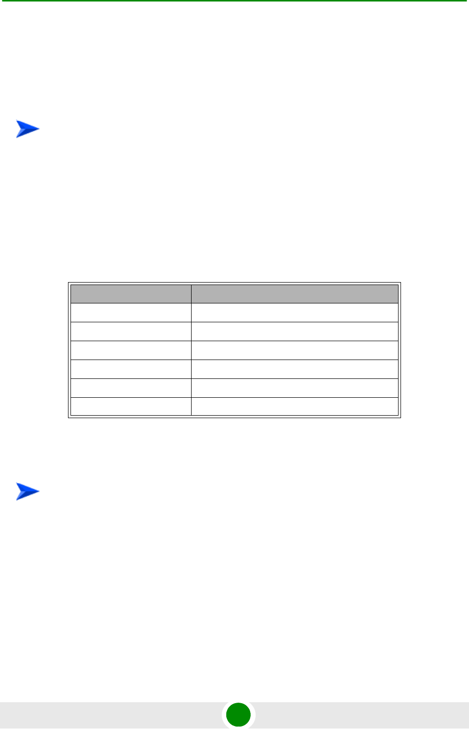
Chapter 4 - Operation and Administration of the Micro BTS The Monitor Program
4Motion 688 System Manual
4.2 T he Monitor Progra m
4.2 .1 Ac c e ssing the M onitor Program
1Use the Monitor cable to connect the MON connector to the COM port of your
ASCII ANSI terminal or PC. The COM port connector on the Monitor cable is a
9 pin D type plug.
2Run a terminal emulation program, such as HyperTerminal™.
3Set the communication parameters as shown in the following table:
The password prompt is displayed. Enter the password and press the Enter key to
get to the Main menu. The default password is “installer”.
1The PC used for accessing the Monitor program should be configured
according to the BTS Management Connectivity parameters (see “Connectivity”
on page 694).
2Run the Telnet program connecting to the IP address of the connected port.
3The Enter the password message is displayed. Enter the password and press
the Enter key to get to the Main menu. The default password is “installer”.
To access the Monitor program via the MON connector:
Table 4-1: COM Port Configuration
Parameter Value
Baud Rate 9600
Data Bits 8
Stop Bits 1
Parity None
Flow Control Xon/Xoff
Port Connected COM port
To access the Monitor program using Telnet:

Chapter 4 - Operation and Administration of the Micro BTS The Monitor Program
4Motion 689 System Manual
4.2 .2 Using the M onitor Program
This section describes the Monitor program structure and navigation rules.
Each menu or submenu specifies the unit type, the management IP address,
the running SW version and a description of the menu.
Each menu or submenu displays a list of numbered options. To access an
option, enter the number of the required option at the > prompt.
At any point in the program, you can use the Esc key to return to the previous
menu (one level up) without applying any change.
The first selectable item in most menus is the Show option, enabling to view
the current configuration of the applicable parameters. For some menus some
additional status information is displayed.
For certain parameters, an updated value is applied only after reset or after
entering a specific command. For these parameters, both Configured and
Current values are displayed in relevant Show menus.
The Update/Add options will display all applicable parameters line by line,
allowing to conveniently edit all of them. The availability and/or value range of
certain parameters may change according to the value selected for a previous
parameter belonging to the same group. The current value is displayed for
each parameter. To keep the current value - press Enter. To change it - enter a
new value and press Enter. The new/modified configuration will take effect
only after completing the configuration process for the all relevant parameters.
Press the Tab key for context sensitive help text (where applicable).
If an erroneous value was entered - the reason of the error or help text will be
displayed, and the parameter entry text will be displayed again.
Many menus include a Select By option, enabling to get a sub-menu for a
selected entity according to the selection criteria. hen prompted to enter
selection criteria, prs the Tab key to display the valid selection values.
If the Monitor program is not used for the period of time defined by the Monitor
Inactivity Time-out (see “Monitor Inactivity Timeout” on page 697), the session
will be terminated automatically.

Chapter 4 - Operation and Administration of the Micro BTS The Monitor Program
4Motion 690 System Manual
Select the Exit option in the Main menu to exit the program and terminate the
session.

Chapter 4 - Operation and Administration of the Micro BTS IP Addresses Configuration
4Motion 691 System Manual
4.3 IP Addresse s Configuration
4.3 .1 IP Address Configuration Restric t ions
1The following IP addresses should not be used and will be rejected:
0.0.0.0
224.0.0.0 - 255.255.255.255 (Multicasts, RFC 3171 D, RFC 1700 E)
4.3 .2 IP Subnets
In a binary representation (32 bits) a Subnet Mask string must comprise a series
of contiguous binary '1's starting from the MSB, followed by a series of contiguous
binary '0's.
Subnet Masks 0.0.0.0 (all zeros, meaning “nothing”) and 255.255.255.255 (all
ones, meaning “this address only”) are illegal and will be rejected.

Chapter 4 - Operation and Administration of the Micro BTS The Main Menu
4Motion 692 System Manual
4.4 T he Ma in Menu
The Main menu of the Monitor program includes the following options:
1 - BTS (see “BTS Menu” on page 693)
2 - Sector (see “Sector Menu” on page 706)
3 - BS (see “BS Menu” on page 708)
4 - Equipment (see “Equipment Menu” on page 735)
5 - GPS (see “GPS Menu” on page 740)
X - Exit (select to exit the Monitor program and terminate the Telnet session)

Chapter 4 - Operation and Administration of the Micro BTS BTS Menu
4Motion 693 System Manual
4.5 BTS M e nu
The BTS menu includes the following options:
“General”
“Connectivity”
“Unit Control”
“Management”
4.5 .1 Ge neral
The BTS General submenu enables viewing the current values and updating the
general BTS parameters. The BTS General parameters are:
“BTS Number”
“BTS Name”
“BTS Address”
“Contact Person”
4.5.1.1 BTS Number
A BTS identifier for management purposes. Should be unique in the managed
network.
The range is from 1 to 999999.
The default is 0. A different number (unique in the managed network) must be
configured.
4.5.1.2 BTS Name
An optional descriptive parameter. A string of up to 32 printable characters.
The default is null (an empty string).
4.5.1.3 BTS Address
An optional descriptive parameter. A string of up to 70 printable characters.

Chapter 4 - Operation and Administration of the Micro BTS BTS Menu
4Motion 694 System Manual
The default is null (an empty string).
4.5.1.4 Contact Person
An optional descriptive parameter. A string of up to 32 printable characters.
The default is null (an empty string).
4.5 .2 Connectivity
The Connectivity submenu includes the following options:
“Management Interface”
“ASN-GW Load Balancing Pools”
“L1 & L2”
4.5.2.1 Management Interface
The Management submenu enables viewing the current values and updating the
Management interface parameters. The Management Interface parameters are:
“VLAN ID”
“Source IP Address”
“IP Subnet mask”
“802.1P Priority”
“DSCP”
“Next Hop Gateway”
4.5.2.1.1 VLAN ID
The VLAN ID to be used with management traffic.
Valid values are 11-100, 110-4094.
The default is 12.
4.5.2.1.2 Source IP Address
The IP address of the Management interface.
The default is 192.168.1.1.

Chapter 4 - Operation and Administration of the Micro BTS BTS Menu
4Motion 695 System Manual
4.5.2.1.3 IP Subnet mask
The Subnet Mask of the Management interface.
The default is 255.255.255.0.
4.5.2.1.4 802.1P Priority
The 802.1P (VLAN) Priority of management traffic.
The range is 0-7.
The default is 0.
4.5.2.1.5 DSCP
The DSCP value of management traffic.
The range is 0-63.
The default is 0.
4.5.2.1.6 Next Hop Gateway
The Default Gateway IP address of the Management interface.
The default is 0.0.0.0 (must be changed to a valid value).
The Default Gateway must be in the subnet of the IP Address.
4.5.2.2 ASN-GW Load Balancing Pools
The Load Balancing feature provides a WiMAX operator with the capability to
build resilient ASN infrastructure using ASN-GW redundancy. Every BS is
provisioned with two lists of redundant ASN-GWs (pools). The BS applies
round-robin mechanism in order to pick an Authenticator for each MS that
performs initial network entry. This should eventually distribute the load between
Anchor ASN-GWs. Geographical site backup can be achieved by using different
priority of ASN-GW pools (Authenticator "metric").
At the unit (BTS) level, up to two pools (with different priorities), each with up to
10 ASN-GWs, can be defined. Each BS defined in the unit will “inherit” these
pools.
The ASN-GW Load Balancing Pools submenu includes two options: Primary Pool
and Secondary Pool. Select the Primary or Secondary Pool option to view or
update the pool’s content. The options available for each pool are:
Show: Select this option to view the current content of the pool.
Add: Select this option to add an address to the pool (up to a maximum of 10
addresses per pool). You will be prompted to define the index for the entry (a

Chapter 4 - Operation and Administration of the Micro BTS BTS Menu
4Motion 696 System Manual
unique number in the range from 1 to 10) before defining the ASN-GW IP
address. An IP address must be unique per both pools.
Select: Use this option to select an entry in the pool by it’s index. You can then
view the entry’s IP address, update the IP address, or delete the entry.
4.5.2.3 L1 & L2
The L1 & L2 option enables viewing or updating the parameters of the Ethernet
interface:
Operational State: The read-only operational status of the port (Up or Down).
Administrative State: The administrative status of the port (Up or Down).
Auto Negotiation: The mode for negotiating the port speed and the duplex
mode with the link partner (Auto or Manual). The default is Auto.
Port Speed: The port speed to be used for the physical interface (valid values
are 10, 100 or 1000 Mbps). Configurable only if Auto Negotiation is set to
Manual. The default is 1000 Mbps.
Duplex Mode: The duplex mode for the interface (Full-Duplex or Half Duplex).
Configurable only if Auto Negotiation is set to Manual. The default is
Full-Duplex.
4.5 .3 Unit Control
The Unit Control menu enables various general control functions such as
resetting the BTS, managing the SW versions of the BTS and
uploading/downloading configuration backup files.
The Unit Control menu includes the following options:
“Reset”
“Monitor Inactivity Timeout”
“SW Version Control”
“TFTP Server”
“Files Control”

Chapter 4 - Operation and Administration of the Micro BTS BTS Menu
4Motion 697 System Manual
“ShutDown Operation”
4.5.3.1 Reset
Select this option to reset the BTS. To avoid unintentional reset, you will be
prompted to confirm the reset request. Changes to some of the configurable
parameters are applied only after reset.
4.5.3.2 Monitor Inactivity Timeout
The Monitor Inactivity Timeout (min) parameter determines the amount of inactive
time following which the unit automatically exits the Monitor program.
The time out duration can range from 0 to 60 minutes. 0 means no inactivity
timeout.
The default value is 10 minutes.
4.5.3.3 SW Version Control
The BTS can contain two SW versions:
Operational: Each time the BTS resets it will reboot using the version defined
as Operational.
Shadow: Normally the Shadow version is the backup version. Each time a new
SW File is downloaded to the BTS, it will be stored as a Shadow version,
replacing the previous Shadow Version.
The typical process of upgrading to a new SW version includes the following steps:
1Download the new SW File to the BTS. It will be stored as the Shadow version.
2Reset and run the BTS from its Shadow version. Note that at this stage, if a
reset were to occur, the BTS will return to the previous Operational version.
3If you want to continue using the new version, swap the Shadow and
Operational versions. The new (currently running) version is now defined as
Operational, and will be used each time the BTS reboots. The previous version
is defined now as Shadow.
Each SW version includes two identifiers:
SW File, which is the name of the downloaded SW file. This name does not
necessarily include clear identification of the SW version number.
SW Version, which provides the SW version number.

Chapter 4 - Operation and Administration of the Micro BTS BTS Menu
4Motion 698 System Manual
The SW Version Control menu includes the following options:
“SW Inventory”
“SW Version Control”
4.5.3.3.1 SW Inventory
Select this option to view the current available versions and the running version:
Operational SW Version Number
Shadow SW Version Number
Current Running SW Source: Operational or Shadow
4.5.3.3.2 SW Version Control
The SW Version Control submenu includes the following options:
“Show SW Versions”
“Show Activation and Status Parameters”
“Load to Shadow”
“Reset and Run from Shadow”
“Set Running Version as Operational”
4.5.3.3.2.1 Show SW Versions
Select this option to view the current available versions and the running version:
Operational SW Version Number
Shadow SW Version Number
Current Running SW Source: Operational or Shadow
4.5.3.3.2.2 Show Activation and Status Parameters
Select this option to view the status of the last requested download operation.

Chapter 4 - Operation and Administration of the Micro BTS BTS Menu
4Motion 699 System Manual
4.5.3.3.2.3 Load to Shadow
The Load to Shadow option enables initiating a process of loading a new SW file to
the BTS. The loaded SW file will be stored as the new Shadow file.
The IP address of the TFTP Server holding the SW file to be loaded is defined by
the TFTP Server parameter (see “TFTP Server” on page 699) You will be
prompted to enter the File Path And File Name (up to 80 characters)
4.5.3.3.2.4 Reset and Run from Shadow
Select the Reset and Run from Shadow option to reset the BTS and run the
Shadow version after power up. To avoid unintentional actions you will be
prompted to confirm the request.
4.5.3.3.2.5 Set Running Version as Operational
When the BTS is running the Shadow version (after selecting Reset and Run from
Shadow), it will boot from the Operational version after the next reset. Select the
Set as Operational option if you want to swap versions so that the running version
will become the Operational version and will be the version to be used after reset.
To avoid unintentional actions you will be prompted to confirm the request.
4.5.3.4 TFTP Server
The TFTP Server option enables viewing or updating the IP address of the TFTP
server to be used for SW download.
4.5.3.5 Files Control
The Files Control submenu enables creating backup files of the BTS configuration
and downloading a configuration file to the BTS.
The Files Control menu includes the following menu options:
“Restore”
“Backup”
“Backup Files”
4.5.3.5.1 Restore
The Restore submenu enables restoring a previously saved backup configuration.
The Restore submenu includes the following options:
4.5.3.5.1.1 Restore From External File
The Restore From External File submenu includes the following options:

Chapter 4 - Operation and Administration of the Micro BTS BTS Menu
4Motion 700 System Manual
Show: Select this option to view the details of the last request for restoring a
configuration file from an external TFTP server. The displayed details include:
»File Name
»TFTP Server IP Address
»Process Status
Update: Select this option to initiate a new process of restoring a configuration
file from an external TFTP server. You will be prompted to define the following
parameters:
»File Name: The path to and file name of the file to be downloaded. A string
comprising 1 to 254 characters.
»TFTP Server IP Address: The IP address of the TFTP Server from which
the file should be loaded.
»Start Download?: Select the download File option to initiate the process.
4.5.3.5.1.2 Restore From Local File
he Restore From Local File submenu includes the following options:
Show: Select this option to view the details of the last request for restoring a
configuration file from the unit’s memory. The displayed details include:
»Restore From Local Backup: noAction or restoretoRAM
»Local File Name
NOTE
To avoid loss of connectivity behind a router, the Management Connectivity parameters are not
changed when loading a Full backup file to the BTS. The values of these parameters configured in
the target BTS before the loading process, are maintained.

Chapter 4 - Operation and Administration of the Micro BTS BTS Menu
4Motion 701 System Manual
Update: Select this option to initiate a new process of restoring a local
configuration file. You will be prompted to define the following parameters:
»Restore From Local Backup: Select noAction or restoretoRAM. If you
selected restoretoRAM, you will be prompted to select the name of the local
file.
»Local File Name: The name of the local backup file to be restored. A string
comprising 1 to 30 characters. Must be the name of one of the existing
backup file (see “Backup Files” on page 701).
4.5.3.5.2 Backup
A backup file of the device’s configuration is created automatically every day. The
Backup submenu enables defining the time of day for execution of the automatic
backup process. You can also initiate a manual request for creation of a backup
file. The BTS holds the last 3 backup files.
The Backup menu includes the following options:
Automatic Configuration Backup: Select to view the current Daily Backup
Time or to update it. The default is 00:00 (midnight).
Create Backup File: Select this option to initiate a request for creating a
backup file of the current configuration or to view the status of last request for
creating a backup file:
»Update: Select to initiate creation of a backup file for the current
configuration.
»Show: Select to view the Process Status of last request for creating a
backup file.
4.5.3.5.3 Backup Files
The Backup Files option enables the viewing the path to and file names of the
current local backup files (up to 3). The file’s name includes its creation date and
time in the format YYYYMMDDHHMM.xml.gz.
4.5.3.6 ShutDown Operation
The ShutDown Operation submenu enables selecting one of the following options:
shutdown: Select this option to shut down the system. To avoid unintentional
shut down, you will be prompted to confirm the request.

Chapter 4 - Operation and Administration of the Micro BTS BTS Menu
4Motion 702 System Manual
reset: Select this option to reset the BTS. To avoid unintentional reset, you will
be prompted to confirm the reset request. Changes to some of the configurable
parameters are applied only after reset.
resettoFactoryDefault: Select this option to restore the factory default
configuration of all BTS parameters. All parameters will revert to their default
values after the next reset. To avoid unintentional action, you will be prompted
to confirm the request.
noAction: Select this option to exit the Shutdown Operation submenu without
any action.
resettoFactoryDefaultwithConnectivity: Select this option to restore factory
default configuration without changing any of the parameters required for
maintaining management connectivity to the unit. To avoid unintentional
action, you will be prompted to confirm the request.
The parameters that are maintained without any change include:
»BTS Name
»Management interfaces parameters
»L1 & L2 parameters
»SNMP Traps Managers configurations
»Authorized Managers configurations
4.5 .4 M ana gement
The Management menu includes the following options:
IMPORTANT
Before shutting down the system, it is recommended that you save the configuration file. The last
saved configuration is used for rebooting the system.
After shutting down the system you cannot restart it from remote. To start up the unit (after shut
down), switch off and then switch on the power supply,
IMPORTANT
Reset to default configuration will affect the ability for remote management of the unit.

Chapter 4 - Operation and Administration of the Micro BTS BTS Menu
4Motion 703 System Manual
“SNMP Traps Managers”
“Authorized Managers”
4.5.4.1 SNMP Traps Managers
Up to 5 SNMP Traps Managers can be defined. The SNMP Trap Managers menu
includes the following options:
“Show”
“Add”
“Select”
4.5.4.1.0.1 Show
Select this option to view the details of the currently defined SNMP Traps
Managers.
4.5.4.1.0.2 Add
Select this option to add a new SNMP Traps Manager. The SNMP Traps Manager
parameters are:
“IP Address”
“Port Number”
“Community”
“Enable Traps Distribution”
4.5.4.1.0.2.1IP Address
The IP address of the Traps Manager.
4.5.4.1.0.2.2Port Number
The port number on which the Trap Manager will listen for messages from the
Agent. The range is from 1 to 65535. The port on which the management system
listens for traps is 162.

Chapter 4 - Operation and Administration of the Micro BTS BTS Menu
4Motion 704 System Manual
4.5.4.1.0.2.3Community
The name of the SNMP Read Community used by the Trap Manager. Traps are
sent toward those Managers for which this parameter is configured. A string of up
to 10 printable characters, case-sensitive.
4.5.4.1.0.2.4Enable Traps Distribution
Indicates whether the sending of traps to the management station is enabled or
disabled.
4.5.4.1.0.3 Select
Use this option to select one of the existing SNMP Traps Managers by its IP
address. You can then view the details of the selected manager, update its
parameters (excluding the IP address) or delete it.
The Selected Manager submenu includes the following options:
Show: For viewing the details of the selected Manager.
Update: For updating the properties of the selected Manager.
Delete: For deleting the selected Manager from the database.
4.5.4.2 Authorized Managers
An SNMP Manager comprises a pair of SNMP Communities (Read Community and
Write Community). A management station is permitted to manage the BTS using
SNMP only if it uses one of the configured SNMP Communities (or a pair of SNMP
Communities). A maximum of five SNMP Managers can be configured. The
Authorized Managers submenu enables defining the properties of management
stations that are allowed to manage the BTS using SNMP.
The Authorized Manager submenu includes the following options:
“Show”
“Add”
“Select”
4.5.4.2.1 Show
Select this option to view the details of all currently defined authorized managers.

Chapter 4 - Operation and Administration of the Micro BTS BTS Menu
4Motion 705 System Manual
4.5.4.2.2 Add
Select this option to add a new authorized manager. Up to 5 Authorized Managers
can be defined. The following parameters can be configured:
“Manager Number”
“Read Community”
“Write Community”
4.5.4.2.2.1 Manager Number
A unique number from 1 to 5.
4.5.4.2.2.2 Read Community
The SNMP Read Community to be used by the Authorized Manager. A null Read
Community means that the read (get) operation can only be performed using the
Write Community.
Valid Community strings: 1 to 32 printable characters, case sensitive.
4.5.4.2.2.3 Write Community
The SNMP Write Community to be used by the Authorized Manager. A null Write
Community means that the Authorized Manager has Read only access rights.
Valid Community strings: 1 to 32 printable characters, case sensitive.
4.5.4.2.3 Select
This option enables selecting an existing authorized manager for viewing or
updating its properties or for deleting it from the database. The selection is based
on the authorized manager's number.
The Selected Manager submenu includes the following options:
Show: For viewing the details of the selected Manager.
Update: For updating the properties of the selected Manager.
Delete: For deleting the selected Manager from the database.
NOTE
The Read and Write Communities are mandatory and both must be defined (other than null).
Duplication of Communities pairs is not allowed (each pair must be unique).

Chapter 4 - Operation and Administration of the Micro BTS Sector Menu
4Motion 706 System Manual
4.6 Sec t or Menu
The unit supports a single sector.
The Sector menu includes the following options:
“Sector Definition”
“Sector Association”
4.6 .1 Se c t or De finition
The Sector Definition menu enables viewing or modifying the sector description
parameters which are informative descriptions for inventory purposes. The Sector
Definition parameters are:
4.6.1.1 Name
The sector name. An optional descriptive string of up to 32 printable characters.
The default is null (an empty string).
4.6.1.2 Heading
The sector heading (the center angle of the sector), in degrees. The range is from 0
to 359.
The heading of an associated Sector cannot be changed. The default is 0.
4.6.1.3 Width
The planned sector coverage, in degrees. The range is from 0 to 359. The default is
0.
4.6 .2 Se c t or Associat ion
The sector association is defined automatically after completing proper definition
of the BS. The Sector Association menu enables viewing the automatically defined
sector association parameter. The sector is defined by the previously configured
BS ID LSB.
The Sector Association includes two association entries, for each of the relevant
AU ports. The parameters for each association are:
Sector Association AU Port Number: 1 and 2

Chapter 4 - Operation and Administration of the Micro BTS Sector Menu
4Motion 707 System Manual
Sector Association Id: 1
Radio Number: 1 and 2
Radio Port Number: 1
Antenna Number: 1 (
Antenna Port Number: 1 and 2
Note: Two vertical antennas are treated as one Antenna with 2 ports

Chapter 4 - Operation and Administration of the Micro BTS BS Menu
4Motion 708 System Manual
4.7 BS Menu
The unit supports a single BS. The BS menu enables defining the BS, updating
the BS parameters or deleting the BS (the BS ID LSB of an existing BS cannot be
modified. To change the BS ID LSB, you must delete the BS and re-define it).
The BS menu includes two options:
“Add”
“Select”
4.7 .1 Add
Select the Add option to define the BS. Only a single BS can be defined. You will
be prompted to configure the following BS mandatory parameters:
4.7.1.1 BS ID LSB
The unique identifier of the BS in the network. A number in the range
1-16777215. The BS ID LSB used in the system is in the format A.B.C where A, B,
C are from 0 to 255. The BS ID used in the Monitor program is an integer that is
calculated by the formula A*65536+B*256+C. For example, a BS ID of 1.2.5 is
translated to 1*65536+2*256+5=66053.
4.7.1.2 Operator ID
The unique identifier of the wireless network operator. The same Operator ID
must be used by all BSs in the managed wireless network. A number in the range
1-16777215 (same definition principle as for BS ID LSB).
4.7.1.3 Center Frequency
The center of the frequency band in which the BS will transmit, in MHz. The valid
values depend on the band supported by the device and the Bandwidth to be
defined, are from f1+0.5BW to f2-0.5BW, where f1 is the lowest frequency of the
radio band, f2 is the highest frequency of the band, and BW is the required
bandwidth.
4.7.1.4 Bandwidth
The BS channel bandwidth (5 MHz, 7 MHz, 10MHz).
A bandwidth of 7 MHz is not applicable for units in the 2.x GHz bands.

Chapter 4 - Operation and Administration of the Micro BTS BS Menu
4Motion 709 System Manual
4.7.1.5 Cell ID
The Cell ID (IDCell) used for preamble selection. The range is from 0 to 31.
4.7.1.6 Segment Number
The segment (BS) number in a three sector BS (0-2).
4.7.1.7 Total Uplink Duration
The total duration of the uplink in a frame, in slots (one slot equals 3 symbols).
To avoid BS-BS interference, the ul-dl-allocation must be identical in all BSs in a
geographical region.
The range is 4-7 or 10 for bandwidth of 5 or 10MHz, 3-5 or 7 for bandwidth of
7MHz.
4.7.1.8 Major Group
The major groups allocated to the BS for maps transmission. Two hexadecimal
digits in the range 00 to fc, representing 8 bits numbered 0 to 7 (left to right). Bits
0 to 5 indicate whether Subchannel Groups 0 to 5 (respectively) are allocated. Bits
6 and 7 are set to 0.
If BW=5 MHz, bits 1, 3 and 5 are not relevant ("don't care"). bits 0, 2, and 4 should
be set. Major Group must be set to A8.
If BW=7/10 MHz with reuse 1, bits 0 to 5 must be set. The value must be set to fc.
For BW=7/10 MHz with Reuse 3:
If Segment Number = 0, then bits #0 and 1 should be set. The value must be
set to c0.
If Segment Number = 1, then bits #2 and 3 should be set. The value must be
set to 30.
If Segment Number = 2, then bits #4 and 5 should be set. The value must be
set to 0c.
4.7.1.9 Basic Map Repetition
The basic repetition used in the transmission of the maps using QPSK 1/2. The
available options are 1, 2, 4 and 6. (1 means no repetitions).

Chapter 4 - Operation and Administration of the Micro BTS BS Menu
4Motion 710 System Manual
4.7.1.10 DL Permutation Base
The permutation base used in the downlink data zone.
The valid range is from 0 to 31.
4.7.1.11 Permutation Base
The permutation base used in the uplink feedback zone.
The valid range is from 0 to 69.
4.7.1.12 UL Permutation Base
The permutation base used in the uplink data zone.
The valid range is from 0 to 69.
4.7.1.13 IP Address
The IP address of the bearer interface of the BS. Must be unique in the network.
Must be in the same subnet with the unit’s bearer interface.
4.7.1.14 IP Subnet Mask
The IP subnet mask of the bearer interface of the BS.
4.7.1.15 Default Gateway
The IP address of the default gateway of the bearer interface of the BS. Must be in
the same subnet with the BS bearer IP Address.
4.7.1.16 Vlan ID
The VLAN ID of the bearer interface of the BS.
The range is 11-100, 110-4094. The default is 11.
4.7.1.17 Default Authenticator IP Address
The IP address of the default authenticator ASN GW.
4.7.1.18 Paging Group ID
The Paging Group ID of the BS.
The range is from 0 to 65535. 0 means that Idle Mode is not enabled. If Idle Mode
is enabled (Paging Group ID is not 0), must be unique in the network (different
Paging Group ID for each BS).

Chapter 4 - Operation and Administration of the Micro BTS BS Menu
4Motion 711 System Manual
4.7 .2 Se lect
Select the BS to view or update its parameters or to delete it. BS is selected by its
BS ID LSB.
The selected BS menu includes the following options:
“General”
“Air Frame Structure Zones”
“Mobility”
“Power Control”
“Feedback”
“Air Frame Structure General”
“Connectivity”
“Management”
“Keep Alive”
“Scheduler”
4.7.2.1 General
The selected BS General parameters menu includes the following options:
Show: Select to view the current values of the BS General parameters.
Update: Select to update the configured values of the BS General parameters.
Delete: Select to delete the BS (the BS ID LSB of an existing BS cannot be
modified. To change it you must delete the BS and re-define it).
The BS General parameters are:
“Operator ID”
“Name”

Chapter 4 - Operation and Administration of the Micro BTS BS Menu
4Motion 712 System Manual
“Center Frequency”
“Bandwidth”
“Paging Group ID”
4.7.2.1.1 Operator ID
The unique identifier of the wireless network operator. The same Operator ID
must be used by all BSs in the managed wireless network. A number in the range
1-16777215. The Operator ID used in the system is in the format A.B.C where A,
B, C are from 0 to 255. The Operator used in the Monitor program is an integer
that is calculated by the formula A*65536+B*256+C. For example, an Operator ID
of 1.1.1is translated to 1*65536+1*256+1=65793.
4.7.2.1.2 Name
The name of the BS. An optional descriptive parameter. A string of up to 32
printable characters.
4.7.2.1.3 Center Frequency
The center of the frequency band in which the BS will transmit, in MHz. The valid
values depend on the band supported by the device and the Bandwidth to be
defined, are from f1+0.5BW to f2-0.5BW, where f1 is the lowest frequency of the
radio band, f2 is the highest frequency of the band, and BW is the required
bandwidth.
4.7.2.1.4 Bandwidth
The BS channel bandwidth (5 MHz, 7 MHz, 10MHz).
A bandwidth of 7 MHz is not applicable for units in the 2.x GHz bands.
4.7.2.1.5 Paging Group ID
The Paging Group ID of the BS.
The single sector Idle Mode capability provides the benefits of MS power savings
and manageable total sector active and non active users, together with reduced
overhead on the backhaul network.
Idle Mode (IM) mechanism allows an MS to become unavailable on the air
interface, and thus freeing operational resources and preserving MS power.
During IM operation, an MS switch off its transmission and reception capabilities,
and becomes available for DL broadcast control messaging, i.e., MS Paging, in a
periodically manner. Using paging broadcast, BS can indicate (if necessary) the
MS to exit from IM and return into normal operation mode. The paging control
message is sent over the DL of a set of BSs simultaneously. This set is called
Paging group (PG). In the current release, each Paging Group includes a single BS.

Chapter 4 - Operation and Administration of the Micro BTS BS Menu
4Motion 713 System Manual
During IM, MS performs location updates when moving from one PG to another.
While in the same PG, MS does not need to transmit in the UL and can be paged
in the DL if there is traffic targeted at it.
The range of the Paging Group ID parameter is from 0 to 65535. 0 means that Idle
Mode is not enabled. If Idle Mode is enabled (Paging Group ID is not 0), must be
unique in the network (different Paging Group ID for each BS).
4.7.2.2 Air Frame Structure Zones
The Air Frame Structure Zones menu includes the following options:
“Uplink Data Zone”
“Downlink Data Zone”
“First Zone”
“Uplink Feedback Zone”
“Frame Structure Mode”
4.7.2.2.1 Uplink Data Zone
The Uplink Data Zone menu enables viewing/updating the values configured for
the following parameters:
“Uplink Basic Rate”
“UL Permutation Base”
4.7.2.2.1.1 Uplink Basic Rate
The uplink basic rate:
ctcQpskOneOverTwoTimesSix (QPSK 1/2 Repetition 6)
ctcQpskOneOverTwoTimesFour (QPSK 1/2 Repetition 4)
ctcQpskOneOverTwoTimesTwo (QPSK 1/2 Repetition 2)
ctcQpskOneOverTwo (QPSK 1/2)
ctcQpskThreeOverFour (QPSK 3/4)

Chapter 4 - Operation and Administration of the Micro BTS BS Menu
4Motion 714 System Manual
ctcQamSixteenOneOverTwo 16-QAM 1/2
ctcQamSixteenThreeOverFour (16-QAM 3/4)
ctcQamSixtyFourOneOverTwo (64-QAM 1/2)
ctcQamSixtyFourTwoOverThree (64-QAM 2/3)
ctcQamSixtyFourThreeOverFour (64-QAM 3/4)
ctcQamSixtyFourFiveOverSix 64-QAM 5/6
The default is ctcQpskOneOverTwo (QPSK 1/2).
4.7.2.2.1.2 UL Permutation Base
The permutation base used in the uplink data zone.
The valid range is from 0 to 69.
4.7.2.2.2 Downlink Data Zone
The Downlink Data Zone menu enables viewing/updating the values configured
for the following parameters:
“Basic Rate for Management”
“Basic Rate for Data”
“DL Permutation Base”
4.7.2.2.2.1 Basic Rate for Management
The downlink basic rate for unicast and broadcast management:
ctcQpskOneOverTwoTimesSix (QPSK 1/2 Repetition 6)
ctcQpskOneOverTwoTimesFour (QPSK 1/2 Repetition 4)
ctcQpskOneOverTwoTimesTwo (QPSK 1/2 Repetition 2)
ctcQpskOneOverTwo (QPSK 1/2)
ctcQpskThreeOverFour (QPSK 3/4)
ctcQamSixteenOneOverTwo 16-QAM 1/2

Chapter 4 - Operation and Administration of the Micro BTS BS Menu
4Motion 715 System Manual
ctcQamSixteenThreeOverFour (16-QAM 3/4)
ctcQamSixtyFourOneOverTwo (64-QAM 1/2)
ctcQamSixtyFourTwoOverThree (64-QAM 2/3)
ctcQamSixtyFourThreeOverFour (64-QAM 3/4)
ctcQamSixtyFourFiveOverSix 64-QAM 5/6
The default is ctcQpskOneOverTwo (QPSK 1/2).
4.7.2.2.2.2 Basic Rate for Data
The downlink basic rate for data:
ctcQpskOneOverTwoTimesSix (QPSK 1/2 Repetition 6)
ctcQpskOneOverTwoTimesFour (QPSK 1/2 Repetition 4)
ctcQpskOneOverTwoTimesTwo (QPSK 1/2 Repetition 2)
ctcQpskOneOverTwo (QPSK 1/2)
ctcQpskThreeOverFour (QPSK 3/4)
ctcQamSixteenOneOverTwo 16-QAM 1/2
ctcQamSixteenThreeOverFour (16-QAM 3/4)
ctcQamSixtyFourOneOverTwo (64-QAM 1/2)
ctcQamSixtyFourTwoOverThree (64-QAM 2/3)
ctcQamSixtyFourThreeOverFour (64-QAM 3/4)
ctcQamSixtyFourFiveOverSix 64-QAM 5/6
The default is ctcQpskOneOverTwo (QPSK 1/2).
4.7.2.2.2.3 DL Permutation Base
The permutation base used in the downlink data zone.
The valid range is from 0 to 31.

Chapter 4 - Operation and Administration of the Micro BTS BS Menu
4Motion 716 System Manual
4.7.2.2.3 First Zone
The First Zone menu enables viewing/updating the values configured for the
following parameters:
“Major Group”
“Basic Map Repetition”
“Minimum Size”
“Maximum Size”
“Maximum Map Size”
4.7.2.2.3.1 Major Group
The major groups allocated to the BS for maps transmission. Two hexadecimal
digits in the range 00 to fc, representing 8 bits numbered 0 to 7 (left to right). Bits
0 to 5 indicate whether Subchannel Groups 0 to 5 (respectively) are allocated. Bits
6 and 7 are set to 0.
If BW=5 MHz, bits 1, 3 and 5 are not relevant ("don't care"). bits 0, 2, and 4 should
be set. Major Group must be set to A8.
If BW=7/10 MHz with reuse 1, bits 0 to 5 must be set. The value must be set to fc.
For BW=7/10 MHz with Reuse 3:
If Segment Number = 0, then bits #0 and 1 should be set. The value must be
set to c0.
If Segment Number = 1, then bits #2 and 3 should be set. The value must be
set to 30.
If Segment Number = 2, then bits #4 and 5 should be set. The value must be
set to 0c.
4.7.2.2.3.2 Basic Map Repetition
The basic repetition used in the transmission of the maps using QPSK 1/2. The
available options are 1, 2, 4 and 6. (1 means no repetitions).
The default is 6 (rate QPSK 1/2 repetition 6)

Chapter 4 - Operation and Administration of the Micro BTS BS Menu
4Motion 717 System Manual
4.7.2.2.3.3 Minimum Size
The initial size (in symbols) of the first zone. When reuse 3 is used within first
zone, this parameter should be equal across all BSs within deployment.
The available options are 2, 4,....34 (2xN where N=1-17) or No Limitation. The
default is No Limitation.
See limitations in “First Zone Minimum Size Recommended Value Range” table
below. Other values should be avoided.
In the current release this is the actual first zone size. For reuse 1 the default (no
limitation) can be used-the actual size will be set dynamically according to the
configuration. For reuse 3 a specific value must be configured.
4.7.2.2.3.4 Maximum Size
Maximum size (in symbols) for first zone. Used mainly for performance control
capability within frame.
The available options are 2, 4,....34 (2xN where N=1-17) or No Limitation. The
default is No Limitation.
Maximum Size cannot be lower than Minimum Size.
In the current release this parameter is not applicable (first zone size is defined
only by the Minimum Size parameter).

Chapter 4 - Operation and Administration of the Micro BTS BS Menu
4Motion 718 System Manual
Recommended values for First Zone Minimum Size and Maximum Size:
* First Zone Scheme is being determined by the selected Map Major Groups:
For 7/10 MHz Full Loading means all Major Groups (0-5) are selected.
For 5MHz Full Loading means that all relevant Major Groups (0, 2, 4) are
selected.
For First Zone Maximum Size the values are:
If First Zone Minimum Size is set to No Limitations, the value range for
Maximum Size is the same as for Minimum Size.
Else, the value range is No Limitations or First Zone Minimum Size+2N, up to
a maximum of Y as defined below.
Table 4-2: First Zone Minimum Size Recommended Value Range
Bandwidth
(MHz)
First Zone
Scheme*
Basic Map Repetition Minimum Size (symbols) (up to a
maximum of Y as defined below)
7/10 Full Loading 6 No Limitation or 8+2N
4 No Limitation or 6+2N
2 No Limitation or 4+2N
1 No Limitation or 4+2N
Reuse 1/3 6 N/A (non trivial configuration)
48+2N
26+2N
16+2N
5 MHz Full Loading 6 N/A (non trivial configuration)
4 No Limitation or 8+2N
2 No Limitation or 6+2N
1 No Limitation or 4+2N
Reuse 1/3 6 N/A (non trivial configuration)
4 N/A (non trivial configuration)
2 N/A (non trivial configuration)
1 N/A (non trivial configuration)

Chapter 4 - Operation and Administration of the Micro BTS BS Menu
4Motion 719 System Manual
The value of Y that sets the upper limit for the Minimum and Maximum Size
parameters depends on the Maximum Cell Radius and Total Uplink Duration
parameters, using the following formula:
Y=A-3*(Total Uplink Duration)-(Extra TTG),
where A=46 for BW of 5 or 10 MHz, and 32 for BW of 7 MHz.
4.7.2.2.3.5 Maximum Map Size
Limits the maximum size of maps (in slots).
The available options are 10, 20 ...300 (10xN where N=1-30) or No Limitation. The
default is No Limitation.
4.7.2.2.4 Uplink Feedback Zone
The Uplink Feedback Zone menu enables viewing/updating the values configured
for the following parameter:
4.7.2.2.4.1 Permutation Base
The permutation base used in the uplink feedback zone.
The valid range is from 0 to 69.
4.7.2.2.5 Frame Structure Mode
The Frame Structure Mode menu enables viewing/updating the values configured
for the following parameter:
4.7.2.2.5.1 RCID Usage
Each transmitted MAP includes allocations for each MS it served, using the MS’s
CID for identifying each MS. The original CID includes 16 bits, which is
significantly more than practically needed since a maximum of 500 MSs can be
served by each BS. To reduce overhead, a smaller number of bits can be used,
based on RCID (Reduced CID) defined in the standard. This mechanism can be
Table 4-3: Calculating the Upper Limit Value (Y) for Minimum and Maximum Size
Bandwidth (MHz) Maximum Cell Radius Total Uplink Duration (slots) Extra TTG (symbols)
5/10 1, 2, 4, 8 4, 6 0
1, 2, 4, 8, 15, 23 5, 7 1
15, 23, 30 4, 6 2
30 5, 7 3
7 1, 2, 4, 8, 15, 23 4 0
1, 2, 4, 8, 15, 23, 30 3, 5 1
30 4 2

Chapter 4 - Operation and Administration of the Micro BTS BS Menu
4Motion 720 System Manual
used only if all MSs served by the BS support RCID. When enabled, CIDs of either
7 or 11 bits will be dynamically used, according to the current number of MS
served at each given moment.
The RCID Usage defines whether RCID is enabled or disabled. The default is
Disable.
4.7.2.3 Mobility
The Mobility menu enables viewing/updating the values configured for the
following parameter:
4.7.2.3.1 Deployment
The type of deployment in the area served by the BS: Fix or Mobile. To support
proper handover, should be set to Fix only if mobile MSs are not expected. The
default is Fix.
4.7.2.4 Power Control
The Power Control menu enables viewing/updating the values configured for the
following parameters:
“Target Ni”
“Required C/N Levels - ACK”
“Required C/N Levels - CQI”
“Required C/N Levels - CDMA”
“Required C/N Levels - QPSK 1/2”
“Required C/N Levels - QPSK 3/4”
“Required C/N Levels -16-QAM 1/2”
“Required C/N Levels - 16-QAM 3/4”
“Required C/N Levels - 64-QAM 1/2”
“Required C/N Levels - 64-QAM 2/3”
“Required C/N Levels -64-QAM 3/4”

Chapter 4 - Operation and Administration of the Micro BTS BS Menu
4Motion 721 System Manual
“Required C/N Levels - 64-QAM 5/6”
“Allowed Interference Level”
4.7.2.4.1 Target Ni
The target noise and interference level for the PUSC zone, in dBm.
The range is from -130 to -110 in steps of 1 (dBm). The default is -127.
4.7.2.4.2 Required C/N Levels - ACK
The C/N in dB required for sending ACK, reported to the MS for power control
purposes.
The range is from -20 to 50 (dB). The default is 7.
4.7.2.4.3 Required C/N Levels - CQI
The C/N in dB required for sending CQI, reported to the MS for power control
purposes.
The range is from -20 to 50 (dB).
Must be in the range from Required C/N Levels - ACK - 8 to Required C/N Levels
- ACK + 7. The default is 12.
4.7.2.4.4 Required C/N Levels - CDMA
The C/N in dB required for transmitting CDMA, reported to the MS for power
control purposes.
The range is from -20 to 50 (dB).
Must be in the range from Required C/N Levels - CQI - 8 to Required C/N Levels -
CQI + 7. The default is 9.
4.7.2.4.5 Required C/N Levels - QPSK 1/2
The C/N in dB required for sending QPSK 1/2, reported to the MS for power
control purposes.
The range is from -20 to 50 (dB).
Must be in the range from Required C/N Levels - CDMA - 16 to Required C/N
Levels - CDMA + 14. The default is 13.
4.7.2.4.6 Required C/N Levels - QPSK 3/4
The C/N in dB required for sending QPSK 3/4, reported to the MS for power
control purposes.
The range is from -20 to 50 (dB).

Chapter 4 - Operation and Administration of the Micro BTS BS Menu
4Motion 722 System Manual
Must be in the range from Required C/N Levels - QPSK 1/2 - 16 to Required C/N
Levels - QPSK 1/2 + 14. The default is 16.
4.7.2.4.7 Required C/N Levels -16-QAM 1/2
The C/N in dB required for transmitting 16-QAM 1/2, reported to the MS for
power control purposes.
The range is from -20 to 50 (dB).
Must be in the range from Required C/N Levels - QPSK 3/4 - 8 to Required C/N
Levels - QPSK 3/4 + 7. The default is 19.
4.7.2.4.8 Required C/N Levels - 16-QAM 3/4
The C/N in dB required for sending 16-QAM 3/4, reported to the MS for power
control purposes.
The range is from -20 to 50 (dB).
Must be in the range from Required C/N Levels - 16-QAM 1/2 - 16 to Required
C/N Levels - 16-QAM 1/2 + 14. The default is 22.
4.7.2.4.9 Required C/N Levels - 64-QAM 1/2
The C/N in dB required for sending 64-QAM 1/2, reported to the MS for power
control purposes.
The range is from -20 to 50 (dB).
Must be in the range from Required C/N Levels - 16-QAM 3/4 - 16 to Required
C/N Levels - 16-QAM 3/4 + 14. The default is 23.
4.7.2.4.10 Required C/N Levels - 64-QAM 2/3
The C/N in dB required for sending 64-QAM 2/3, reported to the MS for power
control purposes.
The range is from -20 to 50 (dB).
Must be in the range from Required C/N Levels - 64-QAM 1/2 - 8 to Required C/N
Levels - 64-QAM 1/2 + 7. The default is 25.
4.7.2.4.11 Required C/N Levels -64-QAM 3/4
The C/N in dB required for sending 64-QAM 2/3, reported to the MS for power
control purposes.
The range is from -20 to 50 (dB).
Must be in the range from Required C/N Levels - 64-QAM 2/3 - 8 to Required C/N
Levels - 64-QAM 2/3 + 7. The default is 26.

Chapter 4 - Operation and Administration of the Micro BTS BS Menu
4Motion 723 System Manual
4.7.2.4.12 Required C/N Levels - 64-QAM 5/6
The C/N in dB required for transmitting 64-QAM 5/6, reported to the MS for
power control purposes.
The range is from -20 to 50 (dB).
Must be in the range from Required C/N Levels - 64-QAM 3/4 - 8 to Required C/N
Levels - 64-QAM 3/4 + 7. The default is 28.
4.7.2.4.13 Allowed Interference Level
This parameter defines the correction of maximum allowed UL SINR based on
measured DL SINR.
The options are Very High, High, Medium, Low.
The default is High.
4.7.2.5 Feedback
The Feedback menu enables viewing/updating the values configured for the
following parameters:
“IR CDMA Allocations Period”
“Start of Ranging Codes Used”
“Maximum Cell Radius”
4.7.2.5.1 IR CDMA Allocations Period
The period of IR CDMA allocations, in frames.
The available options are 1, 2, 4, 6, 8, 10. The default is 2.
In the current release the actual value is always 2 (the configured value is
ignored).
4.7.2.5.2 Start of Ranging Codes Used
The starting number of the group of codes used for the uplink.
The available options are 0, 64, 128, 192. The default is 0.
4.7.2.5.3 Maximum Cell Radius
The maximum cell radius (in km).
The available values are 1, 2, 4, 8, 15, 23. 30. The default is 2.

Chapter 4 - Operation and Administration of the Micro BTS BS Menu
4Motion 724 System Manual
4.7.2.6 Air Frame Structure General
The Air Frame Structure General menu enables viewing/updating the values
configured for the following parameters:
“Cell ID”
“Preamble Group”
“Segment Number”
“Preamble Index”
“Total Uplink Duration”
“Operational Status Channel 1”
“Operational Status Channel 2”
“Neighbor with Beamforming”
4.7.2.6.1 Cell ID
The Cell ID (IDCell) used for preamble selection. The range is from 0 to 31.
4.7.2.6.2 Preamble Group
The preamble group (1 or 2). A value of 2 is applicable only for the following
combinations of Segment Number and Cell ID values:
Segment Number=0, Cell ID=0, 3, 6, 9, 12, 15.
Segment Number=1, Cell ID=1, 4, 7, 10, 13, 16.
Segment Number=2, Cell ID=2, 5, 8, 11, 14, 17
The default is 1.
4.7.2.6.3 Segment Number
The segment (BS) number in a three sector BS (0-2).
4.7.2.6.4 Preamble Index
Read-only. The Preamble Index used by the BS (0-113).
4.7.2.6.5 Total Uplink Duration
The total duration of the uplink in a frame, in slots (one slot equals 3 symbols).

Chapter 4 - Operation and Administration of the Micro BTS BS Menu
4Motion 725 System Manual
To avoid BS-BS interference, the ul-dl-allocation must be identical in all BSs in a
geographical region.
The range is 4-7 or 10 for bandwidth of 5 or 10MHz, 3-5 or 7 for bandwidth of
7MHz.
4.7.2.6.6 Operational Status Channel 1
Read-only. The operational status of Channel 1.
4.7.2.6.7 Operational Status Channel 2
Read-only. The operational status of Channel 2.
4.7.2.6.8 Neighbor with Beamforming
The beam forming mechanism that may be used by neighboring BSs is based on
symmetry in performance between uplink and down link. To compensate for
possible differences due to HW of the ODU, a special low-level calibration signal is
transmitted periodically in each link. During the time this calibration signal is
transmitted all other radio links of the same BS and all its neighbors should not
transmit, to reduce potential interference. The Beam Forming mechanism ensures
that all neighboring BSs operating in Beam Forming mode will enter into silent
mode when necessary. A Micro BTS operating in Matrix A or B mode should enter
into silent mode when necessary (based on frame number information) only if it
has neighboring BSs operating in Beam Forming mode.
The options are Yes and No. Set to Yes only if the unit has at least one neighbor
BS operating in Beam Forming mode.
The default is No.
4.7.2.7 Connectivity
The Connectivity menu includes the following options:
“Bearer Interface”
“Authentication”
“QOS Marking Rules”
“ASN-GW Load Balancing”
4.7.2.7.1 Bearer Interface
The Bearer Interface menu enables viewing/updating the values configured for
the following parameters:

Chapter 4 - Operation and Administration of the Micro BTS BS Menu
4Motion 726 System Manual
“IP Address”
“IP Subnet Mask”
“Default Gateway”
“Vlan ID”
“Default Gateway Connectivity Status”
4.7.2.7.1.1 IP Address
The IP address of the bearer interface of the BS. Must be unique in the network.
Should be in the same subnet, together with the unit’s bearer interface.
4.7.2.7.1.2 IP Subnet Mask
The IP subnet mask of the bearer interface of the BS.
4.7.2.7.1.3 Default Gateway
The IP address of the default gateway of the bearer interface of the BS. Must be in
the same subnet with the BS bearer IP Address.
4.7.2.7.1.4 Vlan ID
The VLAN ID of the bearer interface of the BS. The range is 11-100, 110-4094.
4.7.2.7.1.5 Default Gateway Connectivity Status
Read-only. The status of connectivity with the default authenticator: Unknown,
Up, down. The keep-alive mechanism starts only after first registration at the
ASN-GW. Until then this mechanism is disable and connectivity status is
Unknown.
4.7.2.7.2 Authentication
The Authentication menu enables viewing/updating the values configured for the
following parameters:
“Default Authenticator IP Address”
“Thresholds - Suspended EAP Process”
“Threshold - Active MSs”
“Threshold - Maximum EAP Rounds”
4.7.2.7.2.1 Default Authenticator IP Address
The IP address of the default authenticator ASN GW.

Chapter 4 - Operation and Administration of the Micro BTS BS Menu
4Motion 727 System Manual
4.7.2.7.2.2 Thresholds - Suspended EAP Process
Suspended EAP authentication process threshold. It is used to set an alarm.
The range is 0-10000. The default is 10000.
Note: The relevant alarm is not supported in current release.
4.7.2.7.2.3 Threshold - Active MSs
The threshold for the number of MSs in active operation state (not Idle) served by
the BS. Exceeding this threshold sets the alarm “Excessive MS number”.
The range is 0-1024. When set to 0, the alarm is disabled. The default is 1024.
4.7.2.7.2.4 Threshold - Maximum EAP Rounds
The threshold for the number of EAP rounds in one direction in the same EAP
session. When this threshold is exceeded, alarm is set. This threshold may be
used to protect the system from hazard EAP sessions with extreme number of
messaging round trips.
The range is 0-100. When set to 0, the alarm is disabled. The default is 100.
Note: The relevant alarm is not supported in current release.
4.7.2.7.3 QOS Marking Rules
The QoS Marking Rules menu includes the following options:
“Internal ASN Traffic QOS Rules”
“Internal Management Traffic QOS Rules”
“QOS Rules”
4.7.2.7.3.1 Internal ASN Traffic QOS Rules
The Internal ASN Traffic QOS Rules menu enables viewing/updating the values
configured for the following parameters:
“Diffserv Code Point”
“802.1p Priority”
4.7.2.7.3.1.1Diffserv Code Point
DSCP priority value to be used for marking of intra-ASN (R8/R6) traffic. The range
is 0-63. The default is 0.

Chapter 4 - Operation and Administration of the Micro BTS BS Menu
4Motion 728 System Manual
4.7.2.7.3.1.2802.1p Priority
802.1p priority value to be used for marking of intra-ASN (R8/R6) traffic. The
range is 0-7. The default is 0.
4.7.2.7.3.2 Internal Management Traffic QOS Rules
The Internal Management Traffic QOS Rules menu enables viewing/updating the
values configured for the following parameters:
“Diffserv Code Point”
“802.1p Priority”
4.7.2.7.3.2.1Diffserv Code Point
DSCP priority value to be used for marking of internal management traffic. The
range is 0-63. The default is 0.
4.7.2.7.3.2.2802.1p Priority
802.1p priority value to be used for marking of internal management traffic. The
range is 0-7. The default is 0.
4.7.2.7.3.3 QOS Rules
The QOS Rules menu includes the following options:
Show: Use the Show option to view the main parameters (Rule Status, Marking
Rule Name, Service Flow Data Delivery Type, Service Flow Traffic Priority) of
each of the existing QoS Rules.
Add: Use the Add option to add a new QoS Rule.
Select: Use the Select option to select a specific QoS Rule. You can than select
one of the following:
»Use the Show option to view all parameters of the selected rule.
»Use the Update option to update one or several parameters of the selected
rule.
»Use the Delete option to remove the selected rule from the database.
The QOS Rule parameters are:
4.7.2.7.3.3.1Rule Number
The index number of the rule. A number in the range 1-16383.

Chapter 4 - Operation and Administration of the Micro BTS BS Menu
4Motion 729 System Manual
4.7.2.7.3.3.2Rule Status
The status of the rule (Enable or Disable).
4.7.2.7.3.3.3Marking Rule Name
The name of the QoS Marking Rule. An optional s string of up to 32 characters.
4.7.2.7.3.3.4Service Flow Data Delivery Type
The Service Flow Type for data delivery services: ugs, rtvr, nrtvr, be, ertvr, or ANY.
4.7.2.7.3.3.5Service Flow Traffic Priority
The priority of Service Flow traffic. 0-7 or ANY (255).
4.7.2.7.3.3.6Service Flow Media FlowType
The Service Flow Media Flow Type, as defined in ASN-GW or AAA server
4.7.2.7.3.3.7Enable Service Flow Media Flow Type
Indicates whether the condition for Service Flow Media Flow Type is enabled or
disabled. If true, the Service Flow Media Flow Type will be considered. when
looking for a match.
4.7.2.7.3.3.8Outer DSCP Marking
The DSCP value to be used for marking the outer IP header (IP/GRE). The range is
0-63.
4.7.2.7.3.3.9802.1p Priority Marking
The 802.1p priority to be used for marking traffic. The range is 0-7.
4.7.2.7.4 ASN-GW Load Balancing
At the BTS level, up to two pools (with different priorities), each with up to 10
ASN-GWs, can be defined (see “ASN-GW Load Balancing Pools” on page 695). The
BS will “inherit” these pools. It should be noted the ASN-GW defined in the BS as
the Default Authenticator will be automatically added to the Primary Pool that is
the higher priority pool (although it will not be shown as belonging to the pool).
At the BS level, you can enable/disable the use of each of the two pools. The
Secondary Pool can be enabled only if the Primary Pool is enabled. Note that if
both pools are disabled, or if the enabled pool(s) are empty, the ASN-GW load
balancing feature is disabled and only the Default Authenticator will be used.
The ASN-GW Load Balancing menu includes the following options:
“Pools Availability”

Chapter 4 - Operation and Administration of the Micro BTS BS Menu
4Motion 730 System Manual
“Primary Pool”
“Secondary Pool”
4.7.2.7.4.1 Pools Availability
The Pools Availability option enables viewing/updating the status
(Enabled/Disabled) of each of the pools. The Secondary Pool can be enabled only
if the Primary Pool is enabled.
4.7.2.7.4.2 Primary Pool
The Primary Pool option enables viewing the IP Address and current Connectivity
Status for each of the ASN-GWs in the pool, based on selection of the ASN-GW
Index.
4.7.2.7.4.3 Secondary Pool
The Secondary Pool option enables viewing the IP Address and current
Connectivity Status for each of the ASN-GWs in the pool, based on selection of the
ASN-GW Index.
4.7.2.8 Management
The Management menu includes the following options:
“Noise and Interference Level Thresholds”
“DL Dropped Packets Ratio Thresholds”
4.7.2.8.1 Noise and Interference Level Thresholds
The Noise and Interference Level Thresholds menu enables viewing/updating the
values configured for the following parameter:
4.7.2.8.1.1 Uplink Median Noise
The uplink median noise level represents the median value of the noise floor
histogram. If the uplink median noise level exceeds this value, an excessive uplink
median noise alarm will be generated.
The value is in dBm/tone. The default value of -124 is set to 3 dB above the
default value of the Target NI parameter.
The range is from -135 to -100 (dBm)
4.7.2.8.2 DL Dropped Packets Ratio Thresholds
The DL Dropped Packets Ratio Thresholds menu enables viewing/updating the
values configured for the following parameters:

Chapter 4 - Operation and Administration of the Micro BTS BS Menu
4Motion 731 System Manual
“Best Effort”
“RT-VR”
“NRT-VR”
“UGS”
“ERT-VR”
4.7.2.8.2.1 Best Effort
The threshold for excessive DL dropped packets ratio (in promils), of DL packets in
all Best Effort services, which when exceeded triggers a Best Effort service alarm.
The range is from 1 to 1000 (promil). The default is 1000.
4.7.2.8.2.2 RT-VR
The threshold for excessive DL dropped packets ratio (in promils), of DL packets in
all RT-VR services, which when exceeded triggers an RT-VR service alarm.
The range is from 1 to 1000 (promil). The default is 1000.
4.7.2.8.2.3 NRT-VR
The threshold for excessive DL dropped packets ratio (in promils), of DL packets in
all NRT-VR services, which when exceeded triggers an NRT-VR service alarm.
The range is from 1 to 1000 (promil). The default is 1000.
4.7.2.8.2.4 UGS
The threshold for excessive DL dropped packets ratio (in promils), of DL packets in
all UGS services, which when exceeded triggers a UGS service alarm.
The range is from 1 to 1000 (promil). The default is 1000.
4.7.2.8.2.5 ERT-VR
The threshold for excessive DL dropped packets ratio (in promils), of DL packets in
all ERT-VR services, which when exceeded triggers an ERT-VR service alarm.
The range is from 1 to 1000 (promil). The default is 1000.
4.7.2.9 Keep Alive
The Keep Alive menu enables viewing/updating the values configured for the
following parameters:
“Enable Keep Alive”

Chapter 4 - Operation and Administration of the Micro BTS BS Menu
4Motion 732 System Manual
“Keep Alive Period”
“Polling Period”
“Number of Retransmissions”
4.7.2.9.1 Enable Keep Alive
Enable/disable the keep-alive mechanism. The default is Disable.
The following parameters are applicable only if Keep Alive is enabled.
4.7.2.9.2 Keep Alive Period
Time in milliseconds to wait for a response before initiating another polling
attempt or reaching a decision that the polled entity has failed (if the maximum
number of retries set by Number of Retransmissions has been reached).
The range is from 100 to 10000 milliseconds (0.1 to 10 second). The default is
5000.
4.7.2.9.3 Polling Period
The period in seconds between polling sessions.
The range is from 10 to 1000 seconds. The default is 60 seconds.
Polling Period x 1000 (value in milliseconds) cannot be lower than Keep Alive
Period x (Number of Retransmissions+1)
4.7.2.9.4 Number of Retransmissions
Maximum number of retries if Retransmission Timeout has expired without
getting a response.
The range is from 0 to 10. The default is 5.
4.7.2.10 Scheduler
Scheduling uncommitted (above the maximum reserved rate) traffic can be done
using one of the following options:
Equal Time (ET) scheduling mode, in which air resources are being scheduled
in a fair manner proportional to the users' excess traffic (maximum sustained
rate - maximum reserved rate) SLAs.
Equal Rate (ER) scheduling mode, in which air resources are allocated to users
aiming at ensuring data rate fairness between users proportional to their
excess traffic SLAs.

Chapter 4 - Operation and Administration of the Micro BTS BS Menu
4Motion 733 System Manual
Assuming a sector with diversity (different channels conditions) of active users, ET
scheme enables higher aggregate sector throughput at the expense of data-rate
fairness among users, while ER scheduling scheme ensures maximum data-rate
fairness among users at the expense of lower aggregate sector throughput.
Using ER scheduling scheme exposes the system to excessive allocation of air
resources to highly active users having relatively poorer channel conditions. To
ensure data-rate fairness, more resources will to be allocated to these users
compared to users with relatively good channel conditions. The effect of a small
number of such users within the sector will be reflected by reduced aggregate
sector throughput as well as degradation of achievable rates for all users.
To protect against “abusing” users, an instantaneous rate threshold can be
defined within the scheduling scheme in which the amount of air resources for
users with continuous instantaneous rate below the threshold is being limited.
The more the abusing users' instantaneous rate is below the threshold, the more
resource allocations limitation is applied.
Three levels of dynamic protection are available:
No protection.
Low protection level - Protection against users with very poor channel
conditions. Should be used where the abusing users instantaneous rates are
far below the average instantaneous rate within the sector.
Medium protection - Protection against users with relatively poor or very poor
channel conditions. Should be used where the abusing users instantaneous
rates are below or far below the average instantaneous rate within sector.
A dynamic protection mechanism is implemented, in which the mechanism of
limiting resource allocations is automatically and dynamically activated when
needed.
The Scheduler menu enables viewing/updating the values configured for the
following parameters:
“Scheduler Mode”
“Scheduler DL Abuse Protection Level”
“Scheduler UL Abuse Protection Level”

Chapter 4 - Operation and Administration of the Micro BTS BS Menu
4Motion 734 System Manual
4.7.2.10.1 Scheduler Mode
The basis for allocating excess bandwidth among relevant users:
Equal Rate: Throughput Fairness
Equal Time: Resource Fairness
The selected mode is applicable for both uplink and downlink schedulers.
The default is Equal Rate.
4.7.2.10.2 Scheduler DL Abuse Protection Level
Applicable only if the selected Scheduler Mode is Equal Rate.
None: No Protection
Low: Limit the DL resources allocated to MSs with very low DL transmission
Rate.
Medium: Limit the DL resources allocated to MSs with low and very low DL
transmission Rate.
The default is None.
4.7.2.10.3 Scheduler UL Abuse Protection Level
Applicable only if the selected Scheduler Mode is Equal Rate.
None: No Protection
Low: Limit the UL resources allocated to MSs with very low UL transmission
Rate.
Medium: Limit the UL resources allocated to MSs with low and very low UL
transmission Rate.
The default is None.

Chapter 4 - Operation and Administration of the Micro BTS Equipment Menu
4Motion 735 System Manual
4.8 Equipment Me nu
The Equipment menu includes the following options:
“AU”
“Radio”
“Antenna”
4.8 .1 AU
The AU menu includes the following options:
“General”
“Control”
4.8.1.1 General
The AU General menu enables viewing the general AU properties and status and
updating the Required AU Type.
4.8.1.1.1 Required AU Type
Read-only according to the HW of the unit. In the current release the only
supported AU Type is auMicroOdu2x2 (5).
4.8.1.1.2 AU Installed
Read-only. An indication of AU existence.
4.8.1.1.3 Installed AU Type
Read-only. The detected AU Type.
4.8.1.1.4 HW Version
Read-only. The HW Version of the AU card.
4.8.1.1.5 HW Revision
Read-only. The HW Revision of the AU card.
4.8.1.1.6 Serial Number
Read-only. The Serial Number of the AU card.
4.8.1.1.7 Boot SW Version
Read-only. The Boot SW Version of the AU card.

Chapter 4 - Operation and Administration of the Micro BTS Equipment Menu
4Motion 736 System Manual
4.8.1.1.8 Health
Read-only. The health status of the AU card.
4.8.1.1.9 AU MAC Address
Read-only. The primary MAC address of the AU card.
4.8.1.1.10 AU MAC Address Secondary
Read-only. The secondary MAC address of the AU card.
4.8.1.2 Control
The AU Control menu includes the following parameter:
4.8.1.2.1 Shutdown Power Port 1
This parameter can be used to shutdown power to port 1 of the radio. The default
status is normal operation (no shutdown).
4.8.1.2.2 Shutdown Power Port 2
This parameter can be used to shutdown power to port 2 of the radio. The default
status is normal operation (no shutdown).
4.8.1.2.3 Last Reset Reason
Read-only. The reason for the last reset of the AU. Possible reasons include
Unknown, Health Monitoring Failed, User Initiated. Configuration Failure,
Internal Errors.
4.8 .2 Ra dio
The Radio menu includes the following options for each of the two radios (1 and
2):
“General”
“Port”
4.8.2.1 General
The Radio General menu enables viewing the general radio properties and status
and viewing/updating some general parameters.
4.8.2.1.1 Required Radio Type
The required radio type is set automatically to the value of the actual (installed)
radio type.
Radio Type is in the format oDUAAAABBBBZZZWPPRbyTCOu, where:

Chapter 4 - Operation and Administration of the Micro BTS Equipment Menu
4Motion 737 System Manual
AAAA = Lower bound of frequency band in MHz, rounded up to the nearest
integer.
BBBB = Upper bound of frequency band in MHz, rounded down.
ZZZ = always 000 in TDD systems.
W = always N in TDD systems.
PP = maximum transmit power in dBm, rounded down.
R = number of receive channels.
T = number of transmit channels.
C = Y if cavity filter or a gap in the band is present, N if not.
O = Reserved (0).
u = Indication of a Micro BTS Radio
4.8.2.1.2 Required Frequency Band
Read-only. The frequency band according to the properties defined by the required
radio type.
4.8.2.1.3 Required Maximum TX Power
Read-only. The maximum Tx power according to the properties defined by the
required radio type.
4.8.2.1.4 Required Port Configuration
Read-only. The port configuration according to the properties defined by the
required radio type.
4.8.2.1.5 Installed Radio Type
Read-only. The actually installed radio type. Available only after completing
proper creation of the BS (including a Center Frequency in the correct range) and
configuring a proper value for the Port’s Tx Power parameter. The Serial Number
and the values of the Port’s read-only parameters are available only after detecting
the Installed Radio Type.
4.8.2.1.6 Installed Frequency Band
Read-only. The frequency band according to the properties defined by the
installed radio type.
4.8.2.1.7 Required Maximum TX Power
Read-only. The maximum Tx power according to the properties defined by the
installed radio type.

Chapter 4 - Operation and Administration of the Micro BTS Equipment Menu
4Motion 738 System Manual
4.8.2.1.8 Required Port Configuration
Read-only. The port configuration according to the properties defined by the
installed radio type.
4.8.2.1.9 Serial Number
Read-only. The serial number of the radio card.
4.8.2.2 Port
The Radio Port menu enables viewing the general radio port properties and status
and viewing/updating some general parameters.
4.8.2.2.1 TX Power
The required Tx power at the radio port, in dBm.
The actually available range depends on Radio Type: The upper limit, which is the
default, is set by the Maximum Tx Power supported by the radio. The control
range is 10 dBm.
4.8.2.2.2 HW Revision
Read-only. The HW revision of the radio port card.
4.8.2.2.3 HPA Card
Read-only. An indication whether an HPA (High Power Amplifier) card in installed.
4.8.2.2.4 HPA HW Version
Read-only. Applicable only if HPA card is installed. The HW version of the HPA
card.
4.8.2.2.5 Serial Number
Read-only. The serial number of the radio port card.
4.8.2.2.6 RSSI
Read-only. Average uplink RSSI in dBm of all bursts of all connected MSs.
4.8 .3 Antenna
Typically a 2-ports dual slant antenna is used. In cases where 2 separate
antennas are used, the Antenna parameters are applicable for both antennas.
The Antenna menu enables viewing/updating the following parameters:
4.8.3.1 Antenna Type
An optional descriptive text. Up to 254 characters.

Chapter 4 - Operation and Administration of the Micro BTS Equipment Menu
4Motion 739 System Manual
4.8.3.2 Mechanical Down Tilt
The downwards mechanical tilt of the antenna (in degrees) as opposed to the
electrical tilt already integrated in the antenna (and thus taken as reference;
instead of the horizontal plane). The range is from -90.0 to 90.0 using 0.1 degree
resolution. Used only for information (inventory) purposes. The default is 0.
4.8.3.3 Electrical Down Tilt
The downwards electrical tilt of the antenna, in degrees. The range is from -90.0
to 90.0 using 0.1 degree resolution. Used only for information (inventory)
purposes. The default is 0.
4.8.3.4 Longitude
The longitude of the antenna. The format is lll.mmm,a: lll.is longitude in degrees
(between 000 to 179); mmm is in minutes (between 000 and 999); a - is E (east) or
W (west) Used only for information (inventory) purposes. The default is 000.000,E.
4.8.3.5 Latitude
The latitude of the antenna. The format is ll.mmm,a: ll.is longitude in degrees
(between 00 to 89); mmm is in minutes (between 000 and 999); a - is S (south) or
N (north). Used only for information (inventory) purposes. The default is 00.000,N.
4.8.3.6 Tower Height
The height of the antenna above the ground in meters. The range is from 0 to 500.
Used only for information (inventory) purposes. The default is 0.
4.8.3.7 Heading
The the azimuth angle (in degrees) between the center of the horizontal antenna
beamwidth and the true north; counting clockwise.The range is from 0 to 359.
Used only for information (inventory) purposes. The default is 0.
4.8.3.8 Cable Loss
The attenuation (in dB) of the cable between the ODU port and antenna port. The
range is from 0 to 20 in 0.1 dB steps. Used only for information (inventory)
purposes. The default is 0.5.
4.8.3.9 Antenna Product Type
The antenna type. The available options includes a list of default and standard
antennas. The default is default1portV.

Chapter 4 - Operation and Administration of the Micro BTS GPS Menu
4Motion 740 System Manual
4.9 GPS Menu
The GPS menu includes the following options:
“General Configuration”
“Inventory & Statuses”
4.9 .1 General Configuration
The GPS General Configuration menu enables viewing/updating the following
parameters:
4.9.1.1 GPS Type
The type of time synchronization source to be used. The currently available
options are None and Trimble Lassen.
The default is None,
4.9.1.2 Longitude
The longitude of the site. The format is lll.mmm,a: lll.is longitude in degrees
(between 000 to 179); mmm is in minutes (between 000 and 999); a - is E (east) or
W (west). The default is 000.000,E.
Configurable only if GPS Type set to None. Otherwise they are read-only,
displaying the value calculated by the GPS receiver.
4.9.1.3 Latitude
The latitude of the site. The format is ll.mmm,a: ll.is latitude in degrees (between
00 to 89); mmm is in minutes (between 000 and 999); a - is N (north) or S (south).
The default is 00.000,N.
Configurable only if GPS Type set to None. Otherwise they are read-only,
displaying the value calculated by the GPS receiver.
4.9.1.4 Altitude
The altitude in meters of the site in meters, from -300.0 to 9000.0. The default is
0.
Configurable only if GPS Type set to None. Otherwise they are read-only,
displaying the value calculated by the GPS receiver.

Chapter 4 - Operation and Administration of the Micro BTS GPS Menu
4Motion 741 System Manual
4.9.1.5 UTC Time and Date
The UTC (Coordinated Universal Time) date and time. Configurable only if the GPS
Type is set to None. Otherwise it is the read-only data received from the GPS
receiver.
The format is hh: mm: ss, dd/mm/yyyy
hh between 0 and 23, mm between 0 and 59, ss between 0 and 59, dd/mm with
usual date and month rules, yyyy between 2006 to 9999.
4.9.1.6 Hold Over Passed Timeout
Applicable only if a GPS receiver is used. Defines the period, in minutes, for which
the device provides holdover when the GPS loses synchronization with its
satellites.
The range is from 0 to 2880 minutes. The default is 480 minutes.
4.9.1.7 Stop TX After Hold Over Timeout
Applicable only if a GPS receiver is used. Indicates whether the BTS should stop
data transmission if the GPS lost synchronization with its satellites and the
holdover passed timeout has occurred (Enable/Disable). When enabled, the BTS
will stop transmitting after being in holdover state for more than Holdover Passed
Timeout. The default is Enable.
4.9.1.8 Time Zone Offset From UTC
The offset of the local time from the UTC.
The range is -12:00 to +13:00 in 30 minutes resolution. The default is +00.00.
4.9.1.9 Local Time and Date
A read-only display of the local date and time (using 24-hour clock) as calculated
using the UTC Time and Date and taking into account the Time Zone Offset From
UTC and Daylight Saving Time parameters. The format is: hh:mm:ss;
dd/mm/yyyy.
4.9.1.10 Daylight Saving Mode
The Daylight Saving Mode parameter is used to enable or disable the daylight
saving feature using the following Start Date, Stop Date and Advance Hour Factor
parameters. The default is Disable.

Chapter 4 - Operation and Administration of the Micro BTS GPS Menu
4Motion 742 System Manual
4.9.1.11 Advance Hour Factor
When Daylight Saving is enabled, this parameter defines the amount of time by
which the clock should be advanced during the daylight saving period.
The available values are 0 (daylight saving disabled), 1 and 2 (hours). The default
is 0.
4.9.1.12 Start Date
When Daylight Saving is enabled, this parameter defines the date for starting the
daylight saving feature. At the beginning of this date (midnight at the beginning of
this date), the clock will be advanced by the amount of hours specified by the
Advance Hour Factor.
Use the format dd.mm to define the date and month at which to start activating
the Daylight Saving feature.
4.9.1.13 Stop Date
When Daylight Saving is enabled, this parameter defines the date for ending the
daylight saving feature (at “Advance Hour Factor” hours after midnight at the end
of this date).
Use the format dd.mm to define the date and month at which to end activating the
Daylight Saving feature.
4.9 .2 Inventory & Stat use s
The Inventory & Statuses menu enables viewing the following read-only properties
and status parameters:
4.9.2.1 Navigation Processor SW Version
The software version of the navigation processor of the GPS receiver (if used).
4.9.2.2 Signal Processor SW Version
The software version of the signal processor of the GPS receiver (if used).
4.9.2.3 Number of Satellites
The number of satellites currently acquired by the GPS.
4.9.2.4 1PPS Failure
The status of External 1PPS clock (OK or Failed).

Chapter 4 - Operation and Administration of the Micro BTS GPS Menu
4Motion 743 System Manual
4.9.2.5 4 Satellites and more
Not applicable if a GPS receiver is not connected. Indicating whether 4 (the
minimum required for initial synchronization) or more satellites are received by
the GPS receiver (OK or Failed).
4.9.2.6 2 Satellites and more
Not applicable if a GPS receiver is not connected. Indicating whether 2 (the
minimum number required for maintaining synchronization) or more satellites are
received by the GPS receiver (OK or Failed).
4.9.2.7 GPS Communication Failure
Not applicable if a GPS receiver is not connected. Indicating the status of
communication with the GPS receiver (OK or Failed).
4.9.2.8 Hold Over Entered
Indicating whether the device has entered into Hold Over state (None or Started).
4.9.2.9 Hold Over timeout passed
Indicating whether Hold Over Timeout has passed (None or Passed).
4.9.2.10 BS Stopped to Transmit
Indicating whether the BS is transmitting or not (OK/Stopped)

A
Appendix
Sector Connections Schemes


Appendix A - Sector Connections Schemes Introduction
4Motion 746 System Manual
A.1 I ntroduction
The 4Motion 4-Channels Access Units implement four transmit/receive channels
and are capable of supporting Beam Forming and/or MIMO Matrix A/B
technologies. The operation mode is selected via software, giving the maximal
flexibility to select the appropriate mode for each scenario and for each user.
The 2-Channels Access Units can support only MIMO Matrix A/B technology.
The following sections explain the configurations that support the different
available diversity scenarios.
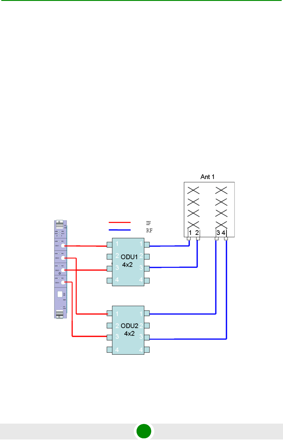
Appendix A - Sector Connections Schemes Fourth Order Diversity, Beam Forming and MIMO
4Motion 747 System Manual
A.2 Fourth Order Diversity, Beam Forming
and MIMO
This section describes the configurations that enable support of both Beam
Forming and MIMO technologies.
Only ODUs that support Beam Forming should be used.
The example is for two 4x2 ODUs, where only the Tx/Rx ports are used. 2x2
ODUs can be used instead, as well as a combinations of one 4x2 ODU and one
2x2 ODU in the same sector (provided that the two ODUs use the same frequency
band).
In the current release a Double Dual Slant (DDP) antenna should be used to
support Beam Forming.
Figure A-1: Beam Forming and MIMO Support with 1 Dual Dual Slant (4-elements) Antenna
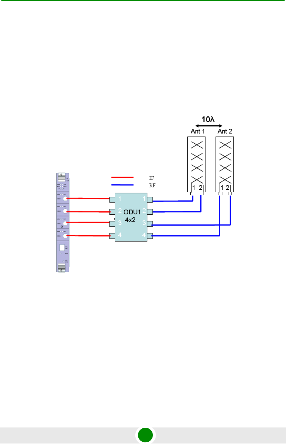
Appendix A - Sector Connections Schemes Fourth Order Diversity, MIMO
4Motion 748 System Manual
A.3 Fourth Orde r Diversity, MI MO
This section describes the configurations that enable support of MIMO
technologies with fourth order diversity.
A.3.1 Wide Double Dual slant Array
Two separated Dual Slant antennas provide also space diversity.
Figure A-2: Two Widely Spaced Dual Slant (2-elements) Antenna
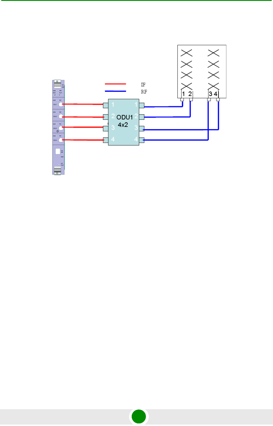
Appendix A - Sector Connections Schemes Fourth Order Diversity, MIMO
4Motion 749 System Manual
A.3.2 Narrow Dual Dual Slant Array
Figure A-3: One Dual Dual Slant (4-elements) Antenna
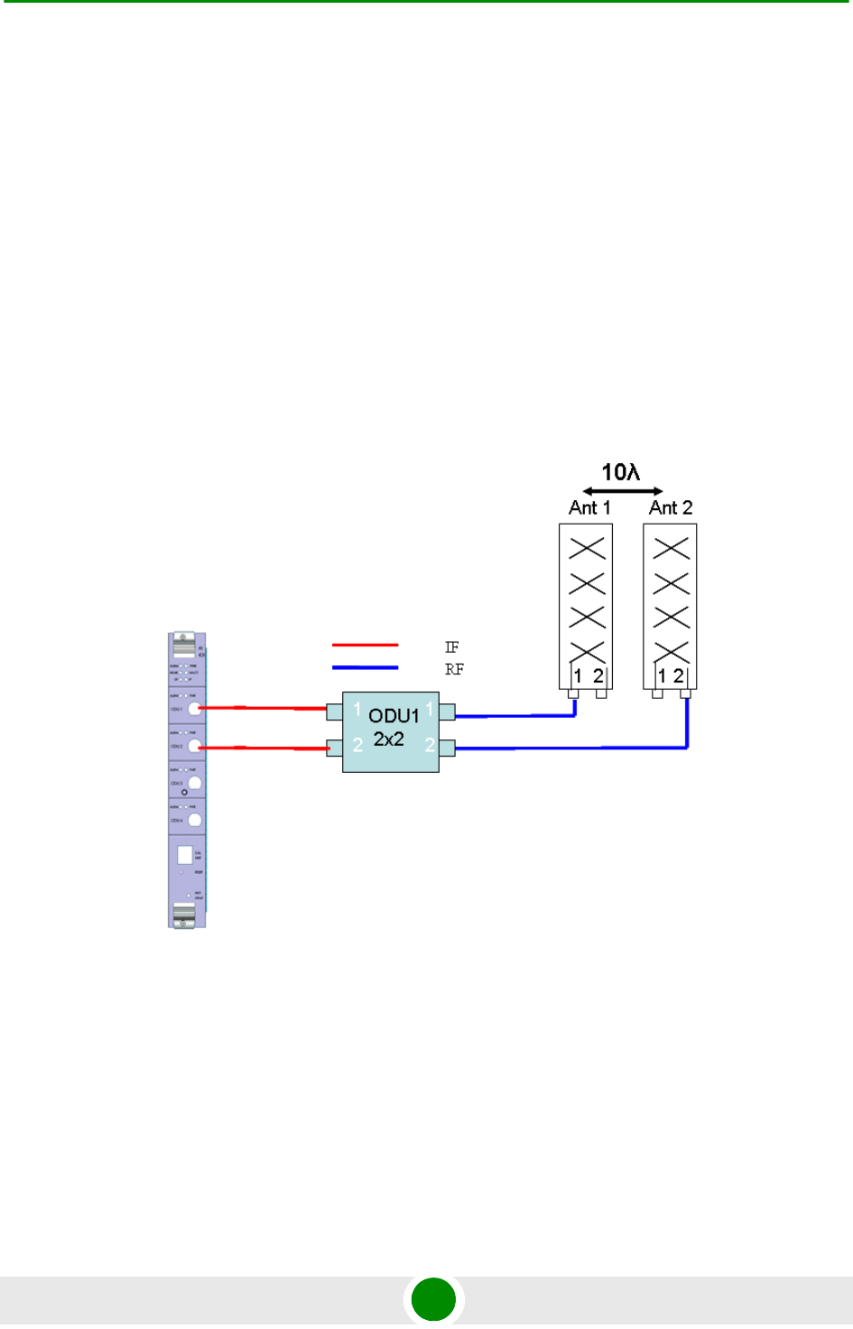
Appendix A - Sector Connections Schemes Second Order Diversity
4Motion 750 System Manual
A.4 Sec ond Order Diversity
All following configuration are shown with one 2x2 ODU. Two 1x1 ODUs can be
used instead of the 2x2 ODU, provided both ODUs support the same frequency
band.
A.4.1 Wide Double Single Slant Array (Space a nd
Pola rization Diversity)
This configuration consists of two dual-slant antennas separated by at least 10
wavelengths, where only one antenna element of each is connected, with different
polarization.
Figure A-4: Wide Double Single Slant Array with Two Partially Used Dual Slant (2-elements)
Antennas
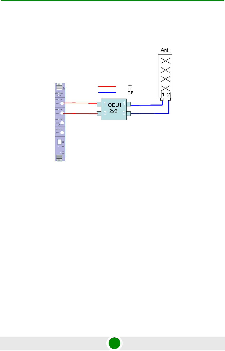
Appendix A - Sector Connections Schemes Second Order Diversity
4Motion 751 System Manual
A.4.2 Narrow Dual Slant Array (Polarizat ion
Dive rsity)
Figure A-5: Narrow Dual Slant Array with One Dual Slant (2-elements) Antenna
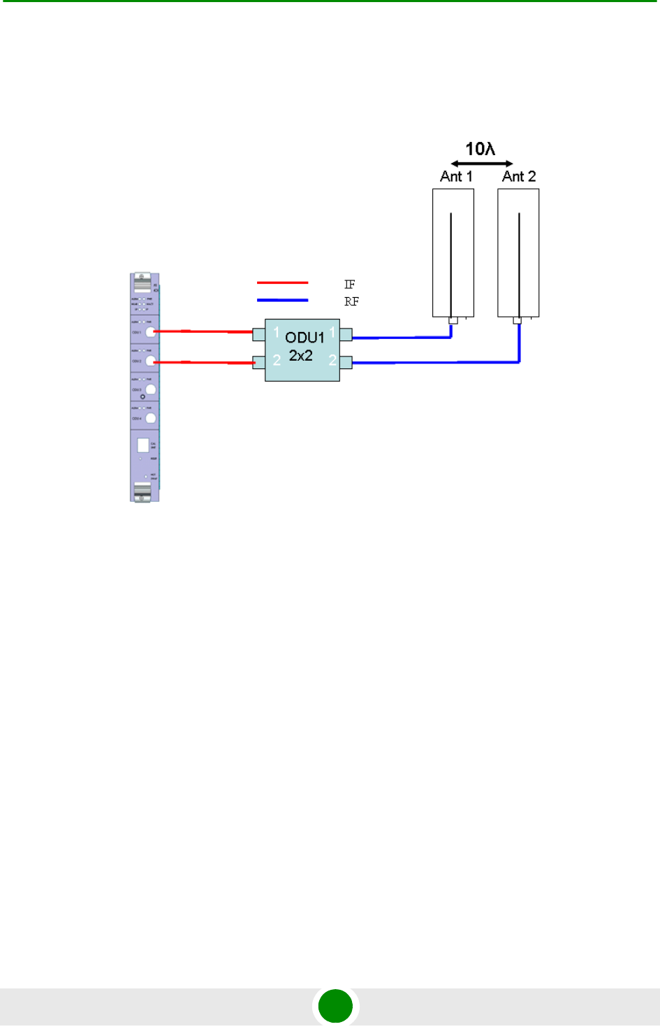
Appendix A - Sector Connections Schemes Second Order Diversity
4Motion 752 System Manual
A.4.3 Wide Array, Vertica l Polarizat ion Ante nna s
(Spac e Diversity)
Figure A-6: Narrow Array with Two Vertical Polarization Antennas

Glossa ry

Glossary
4Motion 911 System Manual
10Base-T An Ethernet cabling standard where data is transmitted in baseband spectrum of a
twisted pair cable (i.e. Cat 3 or better, Cat 5 in most networks) with data rate of 10
Mbps. (10 for 10Mbps, Base for baseband, T for twisted pair). 10Base-T
implementation uses star topology.
100Base-T An Ethernet cabling standard where data is transmitted in baseband spectrum of a
twisted pair cable (i.e. Cat 5 or better), with data rate of 100 Mbps. 100Base-T
implementation uses star topology. 100Base-T is also known as Fast Ethernet.
1000Base-T An Ethernet cabling standard where data is transmitted in baseband spectrum of a
twisted pair cable (Cat 5E or better), with data rate of 1000 Mbps. 1000Base-T
implementation uses star topology. 1000Base-T is also known as Gigabit Ethernet.
3G Third generation wireless service, designed to provide high data speeds, always-on
data access, and greater voice capacity.
AAA Authentication, Authorization, and Accounting (pronounced "triple a."). A system (or
several systems) that controls what resources users have access to, and keeps
track of the activity of users over the network.
AAS Adaptive Antenna System, also called Advanced Antenna System, is a technology to
enable the network operators to increase the wireless network capacity. In addition,
adaptive antenna systems offer the potential of increased spectrum efficiency,
extended range of coverage and higher rate of frequency reuse. Adaptive antenna
systems consist of multiple antenna elements at the transmitting and/or receiving
side of the communication link, whose signals are processed adaptively in order to
exploit the spatial dimension of the mobile radio channel. Depending on whether the
processing is performed at the transmitter, receiver, or both ends of the
communication link, the adaptive antenna technique is defined as multiple-input
single-output (MISO), single-input multiple-output (SIMO), or multiple-input
multiple-output (MIMO).
ACL Access Control List. A filtering mechanism used by many access IP routers that
controls which traffic may be received or transmitted on an interface or port.
AISG Antenna Interface Standards Group. The objective of the group is to facilitate the
introduction of base station antennas with remotely adjustable tilt by agreeing open
standards for the associated data transmission system.
ANSI American National Standards Institute. A voluntary organization composed of
corporate, government, and other members that coordinates standards-related
activities, approves U.S. national standards, and develops positions for the United
States in international standards organizations.
ARP Address Resolution Protocol. Internet protocol used to map an IP address to a MAC
address. Defined in RFC 826.
ARQ Automatic Repeat reQuest. A communication technique in which the receiving
device detects errors and requests retransmissions.
ASCII American Standard Code for Information Interchange. A code for representing
English characters as numbers, with each letter assigned a number from 0 to 127.

Glossary
4Motion 912 System Manual
ASN Access Service Network. An ASN is defined as a complete set of network functions
needed to provide radio access to a WiMAX subscriber. An ASN is comprised of
network elements such as one or more Base Stations (BS) and one or more ASN
gateways (ASN-GW). An ASN may be shared by more than one Connectivity
Service Network (CSN).
ASN-GW Access Service Network Gateway. The ASN-GW is a network entity that acts as a
gateway between the ASN and CSN. The ASN functions hosted in an ASN-GW may
be viewed as consisting of two groups - the decision point (DP) that provides control
functionality and enforcement point (EP) that provides bearer transport.
ASP Application Service Provider. A third-party entity that manages and distributes
software-based services and solutions to customers across a wide area network
from a central data center.
AU Access Unit
AVU Air Ventilation Unit
AWG An electronics industry acronym for American Wire Gauge. AWG is a measure of the
thickness of copper, aluminum and other wiring.
AWGN Additive White Gaussian Noise. Also known as WGN. Constant spectral energy at all
frequencies with a probability histogram that follows a Gaussian bell shaped curve.
BE Best Effort. Service supporting applications with no strict rate or delay requirements.
BS Base Station. The WiMAX BS is an entity that implements the WiMAX MAC and PHY
in compliance with the IEEE 802.16e standard. A BS operates on one frequency
assignment, and incorporates scheduler functions for uplink and downlink resources.
BTS Base Transceiver Station. A wireless network element that provides the radio
interface of the network. The BTS comprises the radio transmission and reception
devices, and also manages the signal processing related to the air interface.
BW Bandwidth
BWA Broadband Wireless Access
CALEA The Communications Assistance for Law Enforcement Act is a United States
wiretapping law passed in 1994. In its own words, the purpose of CALEA is: To
amend title 18, United States Code, to make clear a telecommunications carrier's
duty to cooperate in the interception of communications for Law Enforcement
purposes, and for other purposes. CALEA was intended to preserve the ability of law
enforcement agencies to conduct electronic surveillance by requiring that
telecommunications carriers and manufacturers of telecommunications equipment
modify and design their equipment, facilities, and services to ensure that they have
the necessary surveillance capabilities.

Glossary
4Motion 913 System Manual
CDMA Code Division Multiple Access is a second generation (2G) cellular technology
defined by Qualcomm in IS-95 and IS-2000. A coding scheme, used as a modulation
technique, in which multiple channels are independently coded for transmission over
a single wideband channel. In some communication systems, CDMA is used as an
access method that permits carriers from different stations to use the same
transmission equipment by using a wider bandwidth than the individual carriers. On
reception, each carrier can be distinguished from the others by means of a specific
modulation code, thereby allowing for the reception of signals that were originally
overlapping in frequency and time. Thus, several transmissions can occur
simultaneously within the same bandwidth, with the mutual interference reduced by
the degree of orthogonality of the unique codes used in each transmission.
CE The CE-marking is a European Union regulatory community sign. It symbolizes the
compliance of the product with all essential requirements relating to safety, public
health, consumer protection.
CINR Carrier-to-Interference plus Noise Ratio (expressed in dB)
CIR Committed Information Rate. The rate (in bits per second) at which a network
guarantees to transfer information under normal conditions, averaged over a
minimum increment of time.
CLI Command Line Interface. A user interface that accepts typed commands to instruct
the managed device on the task to perform.
cPCI Compact Peripheral Component Interface. a standard for computer backplane
architecture and peripheral integration, defined and developed by the peripheral
component interconnect (PCI) industrial computers manufacturers group (PICMG).
Designed to provide rugged, high-density systems.
CPU Central Processing Unit.
CQI Channel Quality Information
CS Convergence Sublayer. Particular protocols that are responsible for gathering and
formatting higher layer information so it can be processed by the lower layers.
CSMA/CD Carrier Sense Multiple Access with Collision Detection. Media-access mechanisms
wherein devices ready to transmit data first check the channel for a carrier. If no
carrier is sensed for a specific period of time, a device can transmit. If two devices
transmit at once, a collision occurs and is detected by all colliding devices. This
collision subsequently delays retransmissions from those devices for some random
length of time. Ethernet and IEEE 802.3 use CSMA/CD access.
CSN Connectivity Service Network. A CSN is defined as a set of network functions that
provide IP connectivity services to WiMAX subscribers and all the IP core network
functions. A CSN is comprised of network elements such as routers, proxy/servers,
user databases, and inter-working gateway devices.
CTC Convolutional Turbo Code is a type of turbo codes with some of the convolutional
schemes used. For its high-performance error correction nature, CTC is the iterative
decoding scheme of choice as evidenced by their wide adoption in standards bodies.
DCD Downlink Channel Descriptor.

Glossary
4Motion 914 System Manual
DHCP Dynamic Host Configuration Protocol. A protocol for dynamically assigning IP
addresses from a pre-defined list to nodes on a network. Using DHCP to manage IP
addresses simplifies client configuration and efficiently utilizes IP addresses.
DL Down Link
DSCP Differentiated Service Code Point, AKA DiffServ: An alternate use for the ToS byte in
IP packets. Six bits of this byte are being reallocated for use as the DSCP field
where each DSCP specifies a particular per-hop behavior that is applied to the
packet.
DNS Domain Naming System. A system that stores information about hostnames and
domain names. DNS provides an IP address for each hostname, and lists the e-mail
exchange servers accepting e-mail addresses for each domain.
DoS Denial of Service
DSL Digital Subscriber Line. A technology that exploits unused frequencies on copper
telephone lines to transmit traffic typically at multi-megabit speeds. DSL can allow
voice and high-speed data to be sent simultaneously over the same line. Because
the service is 'always available,' end-users don't need to dial in or wait for call set-up.
EAP Extensible Authentication Protocol, A protocol used between a user station and an
authenticator or authentication server. It acts as a transport for authentication
methods or types. It, in turn may be encapsulated in other protocols, such as 802.1x
and RADIUS. EAP is defined by RFC 2284.
EDT Electrical Down-Tilt
EIRP Equivalent Isotropic Radiated Power. The apparent power transmitted towards the
receiver, if it is assumed that the signal is radiated equally in all directions. The EIRP
is equal to the power (in dBm) at the antenna port, plus the power gained from the
directivity of the antenna (in dBi).
EMC Electro-Magnetic Compatibility. The capability of equipment or systems to be used in
their intended environment within designed efficiency levels without causing or
receiving degradation due to unintentional EMI (Electro Magnetic Interference). EMC
generally encompasses all of the electromagnetic disciplines.
EMS Element Management System. An element management system (EMS) manages
one or more of a specific type of telecommunications network element (NE).
Typically, the EMS manages the functions and capabilities within each NE but does
not manage the traffic between different NEs in the network.
EN Abbreviation for "European Norm".
ERT-VR Extended Real-Time Variable Rate. Service supporting real-time applications with
variable bit rates that require guaranteed data rate, delay and low jitter, such as
voice.
ETS European Telecommunications Standard

Glossary
4Motion 915 System Manual
ETSI European Telecommunications Standards Institute. A non-profit organization
producing voluntary telecommunications standards used throughout Europe, some
of which have been adopted by the EC as the technical base for Directives or
Regulations.
FA Foreign Agent. A mobility agent on the foreign network that can assist the mobile
node in receiving datagrams delivered to the care-of address. (The foreign network
is the network to which the mobile node is attached when it is not attached to its
home network, and on which the care-of-address is reachable from the rest of the
Internet). See also HA (Home Agent).
FCC Federal Communications Commission. A U.S. government agency that supervises,
licenses, and controls electronic and electromagnetic transmission standards.
FEC Forward Error Correction. A method of communicating data that can corrects errors
in transmission on the receiving end. Prior to transmission, the data is put through a
predetermined algorithm that adds extra bits specifically for error correction to any
character or code block. If the transmission is received in error, the correction bits
are used to check and repair the data.
FFT Fast Fourier Transform. An algorithm for converting data from the time domain to the
frequency domain; often used in signal processing.
FTP File Transfer Protocol. A protocol for exchanging files over the Internet. FTP uses the
Internet's TCP/IP protocols to enable data transfer.
GMT Greenwich Mean Time. On January 1, 1972, GMT was replaced as the international
time reference by Coordinated Universal Time (UTC), maintained by an ensemble of
atomic clocks around the world.
GPS Global Positioning System. A system that uses satellites, receivers and software to
allow users to determine their precise geographic position.
GRE General Routing Encapsulation. A method or technique of adding an IP standard
header and trailer to a message that does not follow IP protocols. The encapsulated
message is sent over a public network while received messages are stripped of the
wrapper and processed. This permits non-standard data and totally encrypted
messages to use the Internet. The technology is an important element in Virtual
Private Network (VPN) offerings.
HA Home Agent. A node on the home network (the network at which the mobile node
seems reachable, to the rest of the Internet, by virtue of its assigned IP address) that
effectively causes the mobile node to be reachable at its home address even when
the mobile node is not attached to its home network.
HARQ Hybrid Automatic Repeat reQuest (Hybrid ARQ) is a scheme wherein information
blocks are encoded for partial error correction at receiver and additional, uncorrected
errors are retransmitted.
HO Hand-Over.
HP Abbreviation for "Horizontal Pitch" or standard width measurement which defines the
width for plug-in modules in the 19” construction system. One HP equals 5.08 mm.

Glossary
4Motion 916 System Manual
IANA Internet Assigned Numbers Authority. A regulatory group that maintains all assigned
and registered Internet numbers, such as IP and multicast addresses.
ICMP Internet Control Message Protocol is a protocol designed to allow hosts to send error
and control messages to other network devices. Basically ICMP provides
communication between the Internet Protocol (IP) software on network devices. The
short ICMP messages use IP packets and are usually processed by the IP software,
rather than presented to the user at the application level.
IEC The International Electro-Technical Commission. an international organization that
writes standards for safety for electrical and other equipment. Many IEC standards
were adopted from the German VDE, which was the main historical
standards-writing body in Europe. One goal of the IEC is to harmonize differing
standards between European countries to facilitate free trade. The U.S. Underwriters
Laboratories (UL) and the Canadian CSA are members of the IEC.
IEEE Institute of Electrical and Electronics Engineers. IEEE (pronounced I-triple-E) is an
organization composed of engineers, scientists, and students. The IEEE is best
known for developing standards for the computer and electronics industry. In
particular, the IEEE 802 standards for local-area networks are widely followed.
IEEE 802.16 Also known as WIMAX. A group of broadband wireless communications standards
for metropolitan area networks (MANs) developed by a working group of the IEEE.
IEEE 802.16e 802.16e, also known as 802.16-2005, is an IEEE standard addressing mobility of
wireless broadband (WiMax). IEEE 802.16e is sometimes called Mobile WiMAX,
after the WiMAX forum for interoperability. 802.16e, based on an existing WiMAX
standard 802.16a, adds WiMAX mobility in the 2-to-6 GHz-licensed bands. 802.16e
allows for fixed wireless and mobile Non Line of Sight (NLOS) applications primarily
by enhancing the OFDMA (Orthogonal Frequency Division Multiple Access).
IEEE 802.1p A QoS method - A three-bit value that can be placed inside an 802.1Q frame tag.
IEEE 802.1q The IEEE 802.1q standard defines the operation of VLAN Bridges that permit the
definition, operation and administration of Virtual LAN topologies within a Bridged
LAN infrastructure. The 802.1q specification establishes a standard method for
inserting VLAN membership information into Ethernet frames. A tag field containing
VLAN (and/or 802.1p priority) information can be inserted into an Ethernet frame,
carrying VLAN membership information.
IEEE 802.3 A Local Area Network protocol suite commonly known as Ethernet. Ethernet uses
Carrier Sense Multiple Access bus with Collision Detection CSMA/CD. This method
allows users to share the network cable. However, only one station can use the
cable at a time. A variety of physical medium dependent protocols are supported.
IF Intermediate Frequency. Radio communications systems modulate a carrier
frequency with a baseband signal in order to achieve radio transmission. In many
cases, the carrier is not modulated directly. Instead, a lower IF signal is modulated
and processed. At a later circuit stage, the IF signal is converted up to the
transmission frequency band.

Glossary
4Motion 917 System Manual
IGMP Internet Group Membership Protocol) is protocol used by IP hosts to report their host
group memberships to any immediately neighboring multicast routers.
The use of IP multicasting in TCP/IP networks is defined as a TCP/IP standard in
RFC 1112. In addition to defining address and host extensions for how IP hosts
support multicasting, this RFC also defines the IGMP version 1. Version 2 of IGMP is
defined in RFC 2236. Both versions of IGMP provide a protocol to exchange and
update information about host membership in specific multicast groups.
IP Internet Protocol. The standard that defines how data is transmitted over the
Internet. IP bundles data, including e-mail, faxes, voice calls and messages, and
other types, into "packets", in order to transmit it over public and private networks.
IPv4 Internet Protocol version 4 is still the most commonly used Internet Protocol (IP)
version, initially deployed in 1983. IPv4 addresses are 32-bit numbers often
expressed as 4 octets in "dotted decimal" notation (for example, 192.0.32.67). IPv6
is the newer version of the Internet Protocol (deployment began in 1999) that offers
many improvements over IPv4, such as 128-bit IP addresses, and will eventually
completely replace IPv4.
ISP Internet Service Provider. A company that provides access to the Internet.
KEK Key Encryption Key. Key that encrypts or decrypts other key for transmission or
storage.
LED Light Emitting Diode.
MAC Media Access Control. The lower of the two sub-layers of the data link layer defined
by the IEEE. The MAC sub-layer handles access to shared media, such as whether
token passing or contention will be used.
MAC Address Standardized data link layer address that is required for every port or device that
connects to a LAN. Other devices in the network use these addresses to locate
specific ports in the network and to create and update routing tables and data
structures. MAC addresses are 6bytes long and are controlled by the IEEE.
MDT Mechanical Down-Tilt
MIB Management Information Base. A database of objects that can be monitored by a
network management system. SNMP uses standardized MIB formats that allow any
SNMP tools to monitor any device defined by a MIB.
MIMO Multiple Input, Multiple Output. A technique for faster wireless communication.
MIMO allows for the use of multiple transmitter and receiver antennas to increase
throughput and range.
MIP Mobile IP. A protocol used to provide IP mobility to IPv4-based nodes, defined in
RFC-2002.
MIR Maximum Information Rate. Specifies the maximum rate of information that can be
available to a user. The MIR is used by the traffic policing mechanism to prevent
users from sending excess traffic to the network.

Glossary
4Motion 918 System Manual
MTU Maximum Transmission Unit. This is the greatest amount of data that can be
transferred in one physical frame on the network. If a packet that has a smaller MTU
than the packet's frame length is sent, fragmentation will occur. For TCP MTU can
range from 68 to 1500 bytes. Larger MTUs provide for lower overhead (fewer
headers).
MS Mobile Station. The equipment used by the end user to access the WiMAX network.
NAI Network Address Identifier. Used to create a new unique subscriber identifier, when
a subscriber enters the network without a user name.
NAP Network Access Provider. A NAP is a business entity that provides WiMAX radio
access infrastructure to one or more Network Service Providers (NSPs). An NAP
implements this infrastructure using one or more ASNs.
NAS Network Access Server. A Network Access Server operates as a client of RADIUS.
The client is responsible for passing user information to designated RADIUS
server(s(, and then acting on the response.
NMS Network Management System. A system responsible for managing at least part of a
network. An NMS is generally a reasonably powerful and well-equipped computer,
such as an engineering workstation. NMSs communicate with agents to help keep
track of network statistics and resources.
NOC Network Operations Center. The physical space from which a typically large
telecommunications network is managed, monitored and supervised.
NPU Network Processing Unit
NRT-VR Non Real Time - Variable Rate. Service supporting non-real-time applications with
variable bit rates that require guaranteed data rate and are delay-tolerant such as file
transfers
NSP Network Service Provider. An NSP is a business entity that provides IP connectivity
and WiMAX services to WiMAX subscribers compliant with the established service
level agreement. The NSP concept is an extension of the Internet service provider
(ISP) concept, providing network services beyond Internet access. To provide these
services, an NSP establishes contractual agreements with one or more NAPs. An
NSP may also establish roaming agreements with other NSPs and contractual
agreements with third-party application providers (e.g. ASP, ISP) for the delivery of
WiMAX services to subscribers. From a WiMAX subscriber standpoint, an NSP may
be classified as a home or visited NSP.
NWG Network Working Group. The WiMAX Forum's Network Working Group (NWG) is
responsible for developing the end-to-end network requirements, architecture, and
protocols for WiMAX, using IEEE 802.16e-2005 as the air interface.
OA&M Operation, Administration & Maintenance. Provides the facilities and the personnel
required to manage a network.
OCXO Oven-Controlled crystal oscillator often used in navigation system clocks, frequency
standards, MTI radars, wireless base stations, telecom timing modules and precision
test equipment.
ODU Outdoor Unit

Glossary
4Motion 919 System Manual
OFDM Orthogonal Frequency Division Multiplexing: A method for multiplexing signals,
which divides the available bandwidth into a series of frequencies known as tones.
Orthogonal tones do not interfere with each other when the peak of one tone
corresponds with the null. The rapid switching, frequency-hopping technique is
intended to allow more robust data service.
OFDMA Orthogonal Frequency Division Multiple Access. It’s a logical extension of OFDM
and a modulation/multiple access technique. OFDMA divides a signal into
sub-channels (i.e. groups of carriers), with each sub-channel (or several
sub-channels) being allocated to a different subscriber.
OOB Out-Of-Band. Out-of-band management is a method wherein management
information exchanged between the network element and its associated
management application is carried on a separate communications path from the
user data that is coming to/from the network element. Conversely, in-band (IB)
management is management data that is carried across the same interface as user
data.
OSPF Open Shortest Path First. A link-state IGP (Interior gateway protocol) that makes
routing decisions based on the shortest-path-first (SPF) algorithm (also referred to
as the Dijkstra algorithm).
OSS Operations Support Systems. A system that processes telecommunications
information supporting various management functions, such as billing, customer
care, network management, inventory control, maintenance, trouble ticket reporting,
surveillance and service provisioning; not considered a network element or part of
the network itself.
PDA Personal Digital Assistant. A handheld computing device.
PDU Protocol Data Unit. The concept of a PDU is used in the OSI reference model. From
the perspective of a protocol layer, a PDU consists of information from the layer
above plus the protocol information appended to the data by that layer.. For
example, a frame is a PDU of the Data Link Layer, and a packet is a PDU of the
Network Layer.
PEP Policy Enforcement Point is an entity in a policy-based system where decisions are
enacted.
PER Packet Error Rate. In a digital transmission, PER is the percentage of packets with
errors divided by the total number of packets that have been transmitted, received or
processed over a given time period.
PHS Payload Header Suppression. PHS is a technique used to mask redundant cell,
frame, or packet header information when one or more of the same type of higher
layer data PDUs are transported as the payload of an 802.16 MAC PDU.
PHY PHYsical Layer. The physical, or lowest, layer of the OSI Network Model. In a
wireless network, the PHY defines parameters such as data rates, modulation
method, signaling parameters, transmitter/receiver synchronization, etc. Within an
actual radio implementation, the PHY corresponds to the radio front end and
baseband signal processing sections.

Glossary
4Motion 920 System Manual
PICMG The PCI Industrial Computers Manufacturer's Group is a consortium of over 450
industrial computer product vendors. PICMG's charter is to develop specifications for
PCI-based systems and boards for use in industrial computing applications. PICMG
2.x series is a specification for PCI-based equipment that combines the power of low
cost PCI silicon and software with the rugged Eurocard packaging.
PIM Protocol Independent Multicast. A protocol-independent multicast routing protocol.
PIM sparse mode routes to multicast groups that might span wide-area and
interdomain internets. PIM dense mode is a flood-and-prune protocol.
PIU Power Interface Unit
PKM Privacy Key Management. The key management protocol used in 802.16 to obtain
the needed authorization to use the media. PKM protocol operates in two phases:
AK (Authorization Key) phase, and TEK (Traffic Encryption Keys). AK represents the
secret key used to obtain TEK in the exchanges between MS and BS in subsequent
phases.
PSU Power Supply Unit
PUSC Partial Usage of Sub-Channels
QAM Quadrature Amplitude Modulation. A technique used in wireless applications to
double the available bandwidth by combining two amplitude-modulated signals. The
two combined signals differ in phase by 90 degrees; this technique doubles the
bandwidth by combining the two signals at the source before transmission,
transmitting digital data at a rate of 4 bits per signal change.
QoS Quality of Service. Measure of performance for a transmission system that reflects
its transmission quality and service availability.
QPSK Quadrature Phase Shift Keying. A data transfer technique used in coaxial cable
networks that sends data using modulating signals. Four different phases represent
data, with each signal's information determined by the signal before it. For example,
if a phase stays the same from one signal to the other, the information has not
changed.
RADIUS Remote Authentication Dial-In User Service, an authentication and accounting
system used by many Internet Service Providers (ISPs). When you connect to the
system you must enter your username and password. This information is passed to
a RADIUS server, which checks that the information is correct, and then authorizes
access to the system.
RET Remote Electrical Tilt
RF Radio frequency. An AC signal of high enough frequency to be used for wireless
communications.
RFC Request For Comments. The name of the result and the process for creating a
standard on the Internet. New standards are proposed and published on the Internet,
as a Request For Comments. The proposal is reviewed by the Internet Engineering
Task Force.
RoHS Restriction of the use of certain Hazardous Substances in electrical and electronic
equipment, reference EC Directive 2002/95/EC of 27 January 2003.

Glossary
4Motion 921 System Manual
RS-232 A serial interface published by the EIA (Electronic Industries Association) for
asynchronous data communication over distances up to a few hundred feet.
Characterized by a single-ended (not differential) physical layer, it uses one signal
wire for transmission, another for reception, and a common wire (ground), plus some
timing and control signals.
RS-422 RS-422 is a serial interface standard in which data is sent in a differential pair (two
wires, or twisted pair cable), which allows greater distances and higher data rates
than non-differential serial schemes such as RS-232.
RSSI Received Signal Strength Indicator. A signal or circuit that indicates the strength of
the incoming (received) signal in a receiver.
R&TTE Radio & Telecommunications Terminal Equipment. The R&TTE Directive 1999/5/EC
governs the marketing and use of R&TTE equipment. With the exception of a few
categories of equipment, the Directive covers all equipment, which uses the radio
frequency spectrum. It also covers all terminal equipment attached to public
telecommunication networks.
RTC Real Time Clock.
RTD Round Trip Delay.
RTP Real Time Protocol. An Internet protocol for transmitting real-time data such as audio
and video. RTP itself does not guarantee real-time delivery of data, but it does
provide mechanisms for the sending and receiving applications to support streaming
data. Typically, RTP runs on top of the UDP protocol, although the specification is
general enough to support other transport protocols.
RT-VR Real Time - Variable Rate. Service supporting real-time applications with variable bit
rates that require guaranteed data rate and delay such as streaming video.
Rx Receive
SBS Serving Base Station
SDU Service Data Unit. A set of data that is sent by a user of services of a given layer,
and is transmitted to a peer service user semantically unchanged. The SDU is the
data that a certain layer will pass to the layer below.
SFA Service Flow Authorization.
SFM The Service Flow Manager (SFM) located in the BS is responsible for the creation,
admission, activation, modification, and deletion of IEEE 802.16e-2005 service
flows. It consists of an Admission Control (AC) function, data path function and the
associated local resource information. AC decides whether a new service flow can
be admitted to the system.

Glossary
4Motion 922 System Manual
SNMP Simple Network Management Protocol. A network management protocol that
provides a means to monitor and control network devices, and to manage
configurations, statistics collection, performance, and security. SNMP works by
sending messages, called protocol data units (PDUs), to different parts of a network.
SNMP-compliant devices, called agents, store data about themselves in
Management Information Bases (MIBs) and return this data to the SNMP
requesters.
SSH Secure Shell is a protocol for secure remote login and other secure network services
over an insecure network.
TBS Target Base Station
TCP Transmission Control Protocol. Connection-oriented transport layer protocol that
provides reliable full-duplex data transmission. TCP is the part of the TCP/IP suite of
protocols that is responsible for forming data connections between nodes that are
reliable, as opposed to IP, which is connectionless and unreliable.
TCXO Temperature-Compensated crystal oscillator often used for frequency control in
tactical radios, telecom timing modules (Stratum 3 Type), wireless systems, and
reference oscillators.
TDD Time Division Duplex is a duplexing technique dividing a radio channel in time to
allow downlink operation during part of the frame period and uplink operation in the
remainder of the frame period.
TEK Traffic Encryption Key - a symmetric key that is used to encrypt/decrypt messages.
TFTP Trivial File Transfer Protocol. Simplified version of FTP that allows files to be
transferred from one computer to another over a network, usually without the use of
client authentication.
ToS Type of service. The method of handling traffic using information extracted from the
fields in the ToS byte to differentiate packet flows.
Tx Transmit
TUV TÜV is a safety-testing laboratory with headquarters in Germany. TÜV can test
products for compliance with IEC or VDE requirements. Products that have the TÜV
insignia have been tested by TÜV for compliance with applicable standards for sale
in the European market.
UAbbreviation for "Unit" or standard height measurement which defines the vertical
height for plug-in modules in the 19” construction system. One U equals 44.5 mm.
UCD Uplink Channel Descriptor.
UDP User Datagram Protocol. Connectionless transport layer protocol in the TCP/IP
protocol stack. UDP is a simple protocol that exchanges datagrams without
acknowledgments or guaranteed delivery, requiring that error processing and
retransmission be handled by other protocols. UDP is defined in RFC 768.
UGS Unsolicited Grant Service. Service supporting real-time applications generating
fixed-rate data such as voice over IP without silence suppression.

Glossary
4Motion 923 System Manual
UL 1. Abbreviation for “Underwriters’ Laboratory”. The UL is an independent
organization which conducts safety tests and product certifications.
2. Up Link
UTC Coordinated Universal Time. The reference for the official time used by all countries
in the world, maintained by an ensemble of atomic clocks around the world, and it is
independent from the time zones. The modern implementation of Greenwich Mean
Time.
VLAN Virtual Local Area Network. A group of devices on one or more LANs that are
configured with the same VLAN ID so that they can communicate as if they were
attached to the same wire, when in fact they are located on a number of different
LAN segments. Used also to create separation between different user groups.
VoIP Voice over Internet Protocol. Provides an advanced digital communications network
that bypasses the traditional public switched telephone system and uses the Internet
to transmit voice communication. VoIP enables people to use the Internet as the
transmission medium for telephone calls by sending voice data in packets using IP
rather than by traditional circuit switched transmissions of the PSTN.
WCS Wireless Communications Service is defined by the Federal Communications
Commission as radio communications that may provide fixed, mobile, radio location,
or satellite communication services to individuals and businesses within their
assigned spectrum block and geographical area. The WCS is in the 2.3 GHz band
from 2,305 to 2,320 MHz and 2,345 to 2,360 MHz.
WEEE Waste Electronic and Electrical Equipment. The purpose of Directive 2002/96/EC on
waste electrical and electronic equipment (WEEE) is, as a first priority, the
prevention of waste electrical and electronic equipment (WEEE), and in addition, the
reuse, recycling and other forms of recovery of such wastes so as to reduce the
disposal of waste. It also seeks to improve the environmental performance of all
operators involved in the life cycle of electrical and electronic equipment, e.g.
producers, distributors and consumers and in particular those operators directly
involved in the treatment of waste electrical and electronic equipment.
Wi-Fi Wi-Fi (short for wireless fidelity and pronounced 'why-fye') is a term for certain types
of wireless local area network that use specifications in the IEEE 802.11 family. The
term Wi-Fi was created by an organization called the Wi-Fi Alliance, which oversees
tests that certify product interoperability.
WiMAX WiMAX is an acronym that stands for Worldwide Interoperability for Microwave
Access. WiMAX is a standards-based technology enabling the delivery of last mile
wireless broadband access as an alternative to cable and DSL. WiMAX provides
fixed, nomadic, portable, and mobile wireless broadband connectivity without the
need for direct line-of-sight to a base station.
XML Extensible Markup Language. Language used for defining a set of markers, called
tags, that define the function and hierarchical relationships of the parts of a
document or data set. It is a flexible way to create common information formats and
share both the format and the data, most commonly on the web. It generally similar
to HTML and helps share information in a consistent way. XML is "extensible"
because, unlike HTML, the markup symbols are unlimited and self-defining.