Caretaker Systems 3-204-35 User Manual manual 3of8
Caretaker Systems, Inc. manual 3of8
Contents
manual 3of8
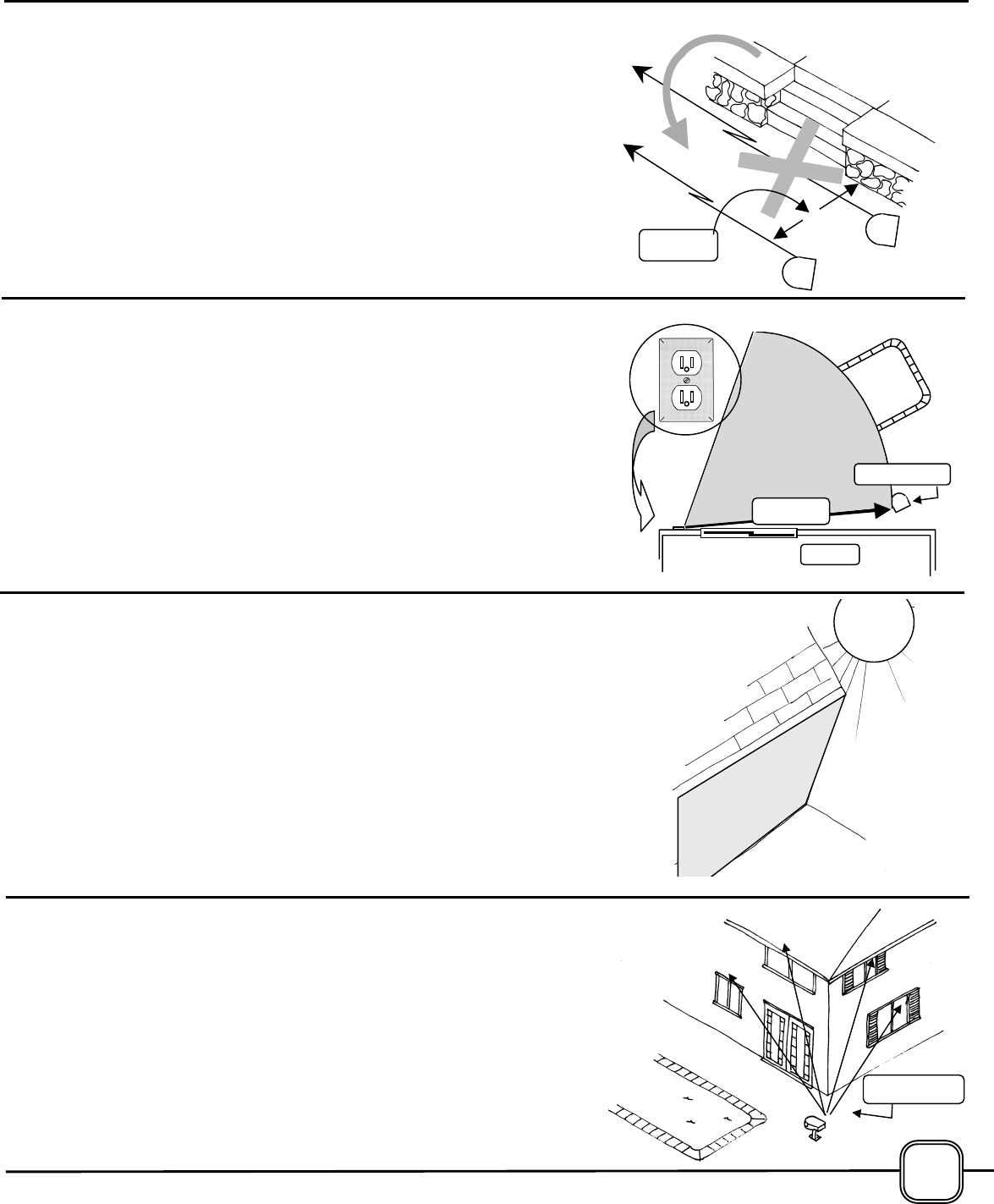
PICTURE THE FROLICKING CHILD
Pay particular attention to low walls, benches, stairways and similar
climbable places when selecting the beam path. If the beam path is
established too close to structures such as these, a child may jump over
the laser beam, defeating the system.
Keep the beam an adequate distance away from such areas if possible.
The objective is to prevent the child from jumping over the beam.
Supplementary fences may have to be erected atop such structures to
assure the maximum in protection if the adequate distance cannot be
achieved.
CONSIDERATIONS
A STANDARD 120 VOLT RECEPTACLE IS REQUIRED
Electric power for the Prevent system is obtained from a step-down
transformer that converts regular 120 volt household current to 12 volts.
The Transformer plugs directly into a standard receptacle as shown at
the right.
The transformer is equipped with a 50 foot (15 meter) power cord fo
r
connection to the Transceiver. This cord length must be considere
d
when selecting a mounting location for the Transceiver. The cord may
be protected by attaching it to a building, suspending from an overhead
trellis, awning or sun screen; or it may be run underground.
THE TRANSCEIVER PREFERS A SHADY SPOT
The Prevent Transceiver was designed and tested to provide years o
f
service in virtually all outdoor climatic conditions. However, because the
system depends upon light from its lasers to function, it is not desirable
to allow the intense light from the sun to shine directly into the
Transceiver.
To assure that the system performs in the manner intended, it is
recommended that the Transceiver not be mounted where it will be
exposed to direct sunlight.
Installation under a shady roof overhang, or where it is protected by
trees or shrubs, eliminating direct sunlight, will provide a highly desirable
added mar
g
in of securit
y
.
House
50
PLAN AHEAD, IF THE OPTIONAL INDOOR ALARM IS TO BE
INSTALLED
A
n optional Indoor Alarm can be linked to the Transceiver through its
own data-link laser beam. This beam, just like the two beams
transmitted by the Transceiver, travels in a straight line. The Indoo
r
A
larm may be mounted in any window that has direct visual access to
the Transceiver.
When planning the installation, it is recommended that this visual access
be confirmed by going into the house and actually looking out of various
windows to assure that an unobstructed view of the transceiver will be
available upon completion of the installation. The Indoor Alarm receiver
sounds an indoor audible alarm
3
7
Transceiv
er
Required for ALL installation Methods
• Pencil or Marker
• Saw
• Builder’s Level
• Square
• Phillips Screwdriver
• Weatherproof Receptacle Cover (optional)
Depending in Installation Method
• Stack of bricks cardboard box (Methods 1A, 1B)
• Masking Tape (1B & 6B)
• 1-1/2” PVC elbow (1C)
• Can gray spray paint (1C)
• Mounting screws and inserts (1C)
• Sack of pre-mix concrete (1B & 6B)
• Wheel-barrel for mixing concrete (1B & 6B)
• Crumpled cardboard or rocks (1B & 6B)
• Trowel or gardening shovel (1B & 6B)
Mounting the Transceiver
Select type of mount A, B,
or C
INSTALLING THE TRANSCEIVER MOUNTING
POST TO THE POOL DECK OR OTHER SOLID,
HORIZONTAL SURFACE
After selecting the location for mounting the
Transceiver and determining the ideal beam path,
proceed as follows:
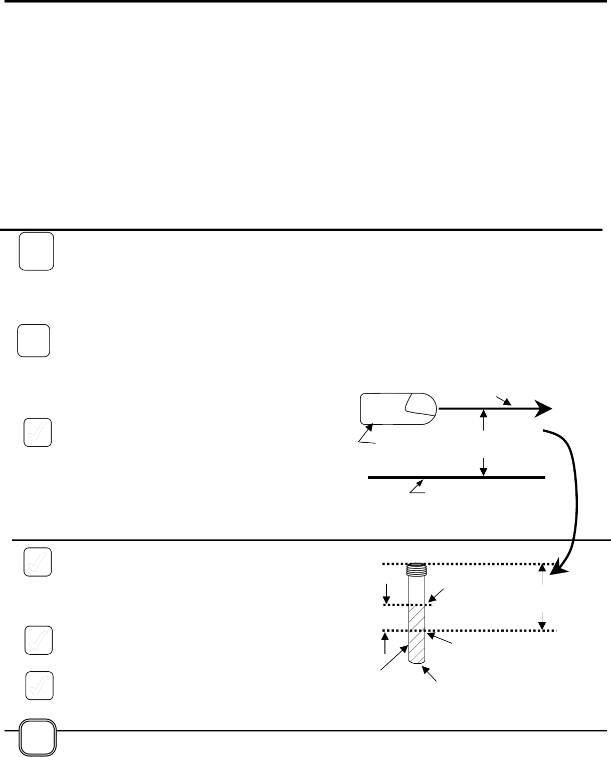
1. Determine the desired height of the beam path
above the mounting surface of the deck or patio
by measuring the distance from the center of the
front face of the Transceiver downward to the
mounting surface. This is accomplished most
easily by having an assistant hold the
Transceiver in position while the measurement is
being taken, or by propping the Transceiver on a
temporary stand such as a cardboard box, a
stack of bricks, or similar structure.
2. Transfer the measurement taken in Step 1,
above, to the Transceiver Mounting Post, which
is the larger Post, with a threaded coupling
bonded onto one end. Start the measurement
from the threaded end and place a mark on the
Mounting Post at the correct point.
3. Make a second mark on the Mounting Post at a
point 4½ inches (11.4 cm) from the first mark,
toward the threaded end of the Post.
4. Cut the Mounting Post at this second mark using
a hacksaw or fine-toothed wood saw. Try to
make the cut square, with no jagged or broken
edges.
TOOLS/MATERIALS REQUIRED
Deck, Patio
or
Desired
Beam Path
Desired Beam
Pth
Transcei
Transceiver
Mounting
Cut
Mark
4½”
Desired
Beam Path
Disca
1
1A
8
Should you need additional length, the material used
for the mounting posts is 1-1/2” schedule 80 PVC
pipe available in hardware or home improvement
stores.
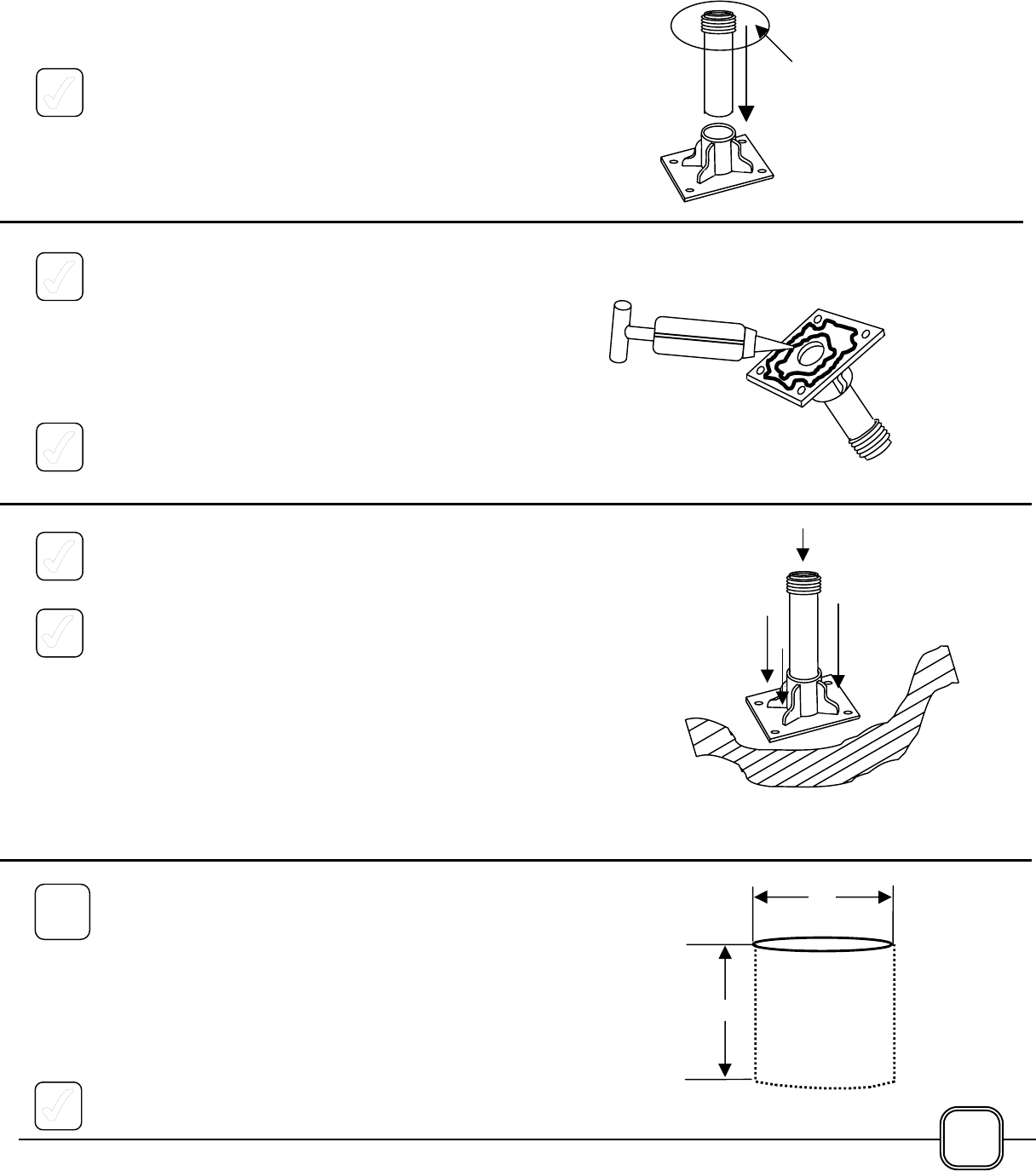
5. Press the Mounting Post into the large hole in
the Mounting Base, making sure there is a very
tight fit. A small amount of epoxy (provided)
should be used for a more secure fit. Protect
the threads of connector with masking tape.
6. Remove the cap from the epoxy and twist a new,
mixing nozzle into place on the end. Insert the
Thum Plunger. (The amount of adhesive
included will bond all bases and posts required.)
Please read the safety precautions included in
with the epoxy.
7. Press the Thum plunger to squeeze out an
appropriate amount of epoxy onto the bottom of
the Mounting Base.
8. Clean and dry the surface on which the
Mounting Base is to be attached to. Remove
any dirt and debris.
9. Press the Mounting Base firmly against the
mounting surface. Depending upon the local
temperature, the epoxy will dry in approximately
15 minutes. DO NOT attempt to install the
Transceiver to the Mounting Post before this
epoxy has set up.
If mounting to deck, skip items
1-B and 1-C and move to Step 2
INSTALLING THE TRANSCEIVER MOUNTING
POST INTO A HOLE IN THE GROUND.
The Transceiver may be mounted directly into the
earth by inserting the Transceiver Mounting Post into
a hole and applying concrete to hold the Transceiver
Mounting Post in an upright, vertical position.
Proceed as follows:
1. In earth, dig a hole 8” (** cm) in diameter and
12” (** cm) deep.
12
8
”
Directly in 9
Wrap with
Masking
Tape
1B